Keysight M9391A PXIe Vector Signal Analyzer and M9381A...
58
K eysight M9391A PXIe Vector Signal Analyzer and M9381A PXIe Vector Signal Generator Notice: This document contains references to Agilent. Please note that Agilent’s Test and Measurement business has become Keysight Technologies. Programming Guide for Creating IVI-COM Console Applications October 24, 2014 Part Number: M9300-90080 © Keysight Technologies, Inc. 2013, 2014
Transcript of Keysight M9391A PXIe Vector Signal Analyzer and M9381A...
Keysight M9391A PXIe Vector
Signal Analyzer and M9381A
PXIe Vector Signal Generator
Notice: This document contains references to Agilent. Please
note that Agilent’s Test and Measurement business has become
Keysight Technologies.
Programming Guide
for Creating IVI-COM
Console Applications
October 24, 2014
Part Number: M9300-90080
© Keysight Technologies, Inc. 2013, 2014
Programming Guide (M9300-90080) 2 of 57
Contents What You Will Learn in this Programming Guide ................................................................................. 4
Related Websites ............................................................................................................................... 4
Related Documentation ..................................................................................................................... 5
Understanding the Overall Process Flow .......................................................................................... 7
Before Programming, Install Hardware, Software, and Software Licenses ........................................ 7
Understanding the Application Programming Interfaces (API) for the AgModularVsa, M9391A PXIe
VSA, and M938xA PXIe VSG ................................................................................................................. 8
IVI Instrument Classes (Defined by the IVI Foundation) ................................................................... 8
IVI Compliant or IVI Class Compliant ................................................................................................ 9
IVI Driver Types .................................................................................................................................. 9
IVI Driver Hierarchy .......................................................................................................................... 10
Instrument-Specific Hierarchies for the AgModularVsa, M9391A, and M938xA .......................... 12
Naming Conventions Used to Program IVI Drivers ............................................................................ 14
General IVI Naming Conventions .................................................................................................... 14
IVI-COM Naming Conventions ........................................................................................................ 14
Tutorial: Create a Project with IVI-COM Using C# ............................................................................. 15
Step 1 – Create a “Console Application” ........................................................................................ 15
Step 2 – Add References ................................................................................................................. 16
Step 3 – Add using Statements ...................................................................................................... 17
To access the IVI drivers without having to specify or type the full path of each interface or
enum ............................................................................................................................................. 17
Step 4 – Create Instances of the IVI-COM Drivers ......................................................................... 18
To create driver instances............................................................................................................ 18
Step 5 – Initialize the Driver Instances ........................................................................................... 19
To determine the VsaResourceName and VsgResourceName .................................................. 19
Set the Initialize()Parameters ........................................................................................... 20
Call the Initialize() Method with the Set Parameters ...................................................... 21
Programming Guide (M9300-90080) 3 of 57
Understanding Initialize Options ................................................................................................. 22
Understanding M9300A Reference Sharing ............................................................................... 24
Step 6 – Write the Program Steps .................................................................................................. 26
Example: Using the Soft Front Panel to Write Program Commands ......................................... 26
Step 7 – Close the Driver ................................................................................................................ 27
Building and Running a Complete Example Program Using Visual C# ............................................. 28
Example Programs ............................................................................................................................... 28
Example Program 1: How to Print Driver Properties, Check for Errors, and Close Driver
Sessions ........................................................................................................................................ 28
Understanding PA / FEM Measurements ........................................................................................... 36
Test Challenges Faced by Power Amplifier Testing........................................................................ 37
Performing a Channel Power Measurement, Using Immediate Trigger ........................................ 38
Example Program 2: How to Perform Channel Power Measurement, Using Immediate Trigger
(Settings for WCDMA Signal) ...................................................................................................... 38
Performing a WCDMA Power Servo and ACPR Measurement ...................................................... 43
Example Program 3: How to Perform a WCDMA Power Servo and ACPR Measurement ...... 43
Accessing Hardware-Specific Capabilities ......................................................................................... 50
Glossary ............................................................................................................................................... 56
References ........................................................................................................................................... 57

Programming Guide (M9300-90080) 4 of 57
What You Will Learn in this Programming Guide This programming guide is intended for individuals who write and run programs to control test-
and-measurement instruments. Specifically, in this programming guide, you will learn how to use
Visual Studio 2008 with the .NET Framework to write IVI-COM Console Applications in Visual C#.
Knowledge of Visual Studio 2008 with the .NET Framework and knowledge of the programming
syntax for Visual C# is required.
Our basic user programming model uses the IVI-COM driver directly and allows customer code to:
access the IVI-COM driver at the lowest level
access IQ Acquisition Mode, Power Acquisition Mode, and Spectrum Acquisition Mode
control the Keysight M9391A PXIe Vector Signal Analyzer (VSA) and
Keysight M9381A PXIe Vector Signal Generator (VSG) while performing
Power Amplifier (PA) / Front End Module (FEM) Production Tests
generate waveforms created by Signal Studio software (licenses are required)
IVI-COM Console Applications that are covered in this programming
guide are used to perform acquisition measurements with the
AgModularVsa or
M9391A PXIe VSA from signals that are created with the M9381A PXIe
VSG.
The following PA / FEM Power Measurement Production Tests are covered:
Example Program 1: How to Print Driver Properties, Check for Errors, and Close Driver
Sessions
Example Program 2: How to Perform a Channel Power Measurement, Using Immediate
Trigger
Example Program 3: How to Perform a WCDMA Power Servo and ACPR Measurement
Related Websites
Keysight Technologies PXI and AXIe Modular Products
o M9391A PXIe Vector Signal Analyzer
o M9381A PXIe Vector Signal Generator
Programming Guide (M9300-90080) 5 of 57
Keysight Technologies
o IVI Drivers & Components Downloads
o Keysight I/O Libraries Suite
o GPIB, USB, & Instrument Control Products
o Keysight VEE Pro
o Technical Support, Manuals, & Downloads
o Contact Keysight Test & Measurement
IVI Foundation - Usage Guides, Specifications, Shared Components Downloads
MSDN Online
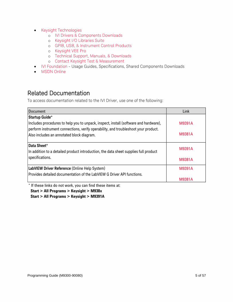
Related Documentation To access documentation related to the IVI Driver, use one of the following:
Document Link
Startup Guide*
Includes procedures to help you to unpack, inspect, install (software and hardware),
perform instrument connections, verify operability, and troubleshoot your product.
Also includes an annotated block diagram.
M9391A
M9381A
Data Sheet*
In addition to a detailed product introduction, the data sheet supplies full product
specifications.
M9391A
M9381A
LabVIEW Driver Reference (Online Help System)
Provides detailed documentation of the LabVIEW G Driver API functions.
M9391A
M9381A
* If these links do not work, you can find these items at:
Start > All Programs > Keysight > M938x
Start > All Programs > Keysight > M9391A
Programming Guide (M9300-90080) 6 of 57
Programming Guide (M9300-90080) 7 of 57
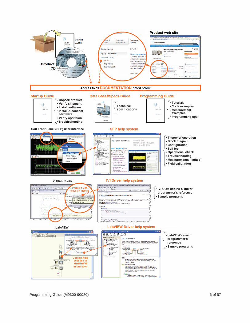
Understanding the Overall Process Flow Write source code using Microsoft Visual Studio 2008 with .NET Visual C# running on
Windows 7.
Compile Source Code using the .NET Framework Library.
Produce an Assembly.exe file – this file can run directly from Microsoft Windows without
the need for any other programs. When using the Visual Studio Integrated Development
Environment (IDE), the Console Applications you write are stored in conceptual containers
called Solutions and Projects. You can view and access Solutions and Projects using the
Solution Explorer window (View > Solution Explorer).
Before Programming, Install Hardware, Software, and Software
Licenses Step 1. Install Microsoft Visual Studio 2008 with .NET Visual C# running on Windows 7.
You can also use a free version of Visual Studio Express 2010 tools from:
http://www.microsoft.com/visualstudio/eng/products/visual-studio-2010-express
The following steps, defined in the Keysight M9391A PXIe VSA and M9381A PXIe VSG
Startup Guide, M9300-90090, but repeated here must be completed before
programmatically controlling the M9391A PXIe VSA and M9381A PXIe VSG hardware with
these IVI drivers.
Step 2. Unpack and inspect all hardware.
Step 3. Verify the shipment contents.
Step 4. Install the software. Note the following order when installing software!
(If you run the installation .exe, all of these are installed automatically.)
Install Keysight IO Libraries Suite (IOLS), Version 16.3.16603.3 or newer; this installation includes
Keysight Connections Expert.
(Optional) Install Keysight 89600 Vector Signal Analyzer Software, Version 15 or newer.
Install the M938xA PXIe VSG driver software, Version 1.2.525.1 or newer.
Install the M9391A PXIe VSA driver software, includes AgModularVsa, Version 1.0.0.0 or newer
Driver software includes all IVI-COM, IVI-C, and LabVIEW G Drivers along with
Soft Front Panel (SFP) programs and documentation.
All of these items may be downloaded from the Keysight product websites:
o http://www.keysight.com/find/iosuite
o http://www.keysight.com/find/ivi - download installers for Keysight IVI-COM
drivers
o http://www.keysight.com/find/m9391a > Select Technical Support > Select the Drivers,
Firmware & Software tab > Download the Instrument Driver.
Programming Guide (M9300-90080) 8 of 57
o http://www.keysight.com/find/m9381a > Select Technical Support > Select the Drivers,
Firmware & Software tab > Download the Instrument Driver.
Step 5. Install the hardware modules and make cable connections.
Step 6. Verify operation of the modules (or the system that the modules create).
Note: Before programming or making measurements, conduct a Self-Test on both the
M9391A PXIe VSA and M9381A PXIe VSG to make sure there are no problems with the
modules, cabling, or backplane trigger mapping.
Once the software and hardware are installed and verification of operation has been performed, they are
ready to be programmatically controlled.
Understanding the Application Programming Interfaces (API)
for the AgModularVsa, M9391A PXIe VSA, and M938xA PXIe VSG The following IVI driver terminology may be used throughout this programming guide.
IVI [Interchangeable Virtual Instruments] — a standard instrument driver model defined by the
IVI Foundation that enables engineers to exchange instruments made by different
manufacturers without rewriting their code. www.ivifoundation.org
Currently, there are 13 IVI Instrument Classes defined by the IVI Foundation. The AgModularVsa,
the M9391A PXIe VSA, and the M9381A PXIe VSG do not belong to any of these 13 IVI Instrument
Classes and are therefore describes as “NoClass” modules.
IVI Instrument Classes (Defined by the IVI Foundation) DC Power Supply
AC Power Supply
DMM
Function Generator
Oscilloscope
Power Meter
RF Signal Generator
Spectrum Analyzer
Switch
Upconverter
Downconverter

Programming Guide (M9300-90080) 9 of 57
Digitizer
Counter/Timer
IVI Compliant or IVI Class Compliant AgModularVsa, M9391A PXIe VSA, and M9381A PXIe VSG are IVI Compliant, but not IVI Class
Compliant; they each do not belong to one of the 13 IVI Instrument Classes defined by the IVI
Foundation.
IVI Compliant – means that the IVI driver follows architectural specifications for these
categories:
o Installation
o Inherent Capabilities
o Cross Class Capabilities
o Style
o Custom Instrument API
IVI Class Compliant – means that the IVI driver implements one of the 13 IVI Instrument
Classes
o If an instrument is IVI Class Compliant, it is also IVI Compliant
o Provides one of the 13 IVI Instrument Class APIs in addition to a Custom API
o Custom API may be omitted (unusual)
o Simplifies exchanging instruments
IVI Driver Types
IVI Driver
Programming Guide (M9300-90080) 10 of 57
o Implements the Inherent Capabilities Specification
o Complies with all of the architecture specifications
o May or may not comply with one of the 13 IVI Instrument Classes
o Is either an IVI Specific Driver or an IVI Class Driver
IVI Specific Driver
o Is an IVI Driver that is written for a particular instrument such as the M9391A PXIe
VSA or M938xA PXIe VSG
IVI Class Driver
o Is an IVI Driver needed only for interchangeability in IVI-C environments
o The IVI Class may be IVI-defined or customer-defined
IVI Class-Compliant Specific Driver
o IVI Specific Driver that complies with one (or more) of the IVI defined class
specifications
o Used when hardware independence is desired
IVI Custom Specific Driver
o IVI Specific Driver that is not compliant with any one of the IVI defined class
specifications
o Not interchangeable
o Keysight has created a common Vector Signal Analyzer (VSA) interface
(IAgModularVsa) that provides commonality between the M9391A PXIe VSA and
future Keysight modular vector signal analyzers. This common modular VSA class
will make the VSA’s interface-compatible, which makes transitioning software
between them extremely easy. Any instrument-specific capability can still be
accessed via the instrument-specific interface (i.e. IAgM9391).
IAgModularVsa is the root interface and contains references to child
interfaces, which in turn contain references to other child interfaces.
Collectively, these interfaces define the instrument-specific hierarchy for
the IAgModularVsa.
IVI Driver Hierarchy When writing programs, you will be using the interfaces (APIs) available to the IVI-COM driver.
The core of every IVI-COM driver is a single object with many interfaces.
These interfaces are organized into two hierarchies: Class-Compliant Hierarchy and
Instrument-Specific Hierarchy – and both include the IIviDriver interfaces.
o Class-Compliant Hierarchy - Since the AgModularVsa, M9391A PXIe VSA, and
M9381A PXIe VSG do not belong to one of the 13 IVI Classes, there is no
Class-Compliant Hierarchy in their IVI Driver.
o Instrument-Specific Hierarchy
The AgModularVsa has a Common Vector Signal Analyzer (VSA) interface
Programming Guide (M9300-90080) 11 of 57
(IAgModularVsa) and provides commonality between the M9391A PXIe VSA
and future Keysight modular vector signal analyzers. This common modular
VSA class will make the VSAs interface-compatible, which makes
transitioning software between them extremely easy. Any instrument-
specific capability can still be accessed via the instrument-specific interface
(i.e. IAgM9391).
IAgModularVsa is the root interface and contains references to child
interfaces, which in turn contain references to other child interfaces.
Collectively, these interfaces define the instrument-specific
hierarchy.
The M9391A PXIe VSA’s instrument-specific hierarchy has IAgM9391 at the
root (where AgM9391 is the driver name).
IAgM9391 is the root interface and contains references to child
interfaces, which in turn contain references to other child interfaces.
Collectively, these interfaces define the instrument-specific
hierarchy.
The M938xA PXIe VSG’s instrument-specific hierarchy has IAgM938x at the
root (where AgM938x is the driver name).
IAgM938x is the root interface and contains references to child
interfaces, which in turn contain references to other child interfaces.
Collectively, these interfaces define the instrument-specific
hierarchy.
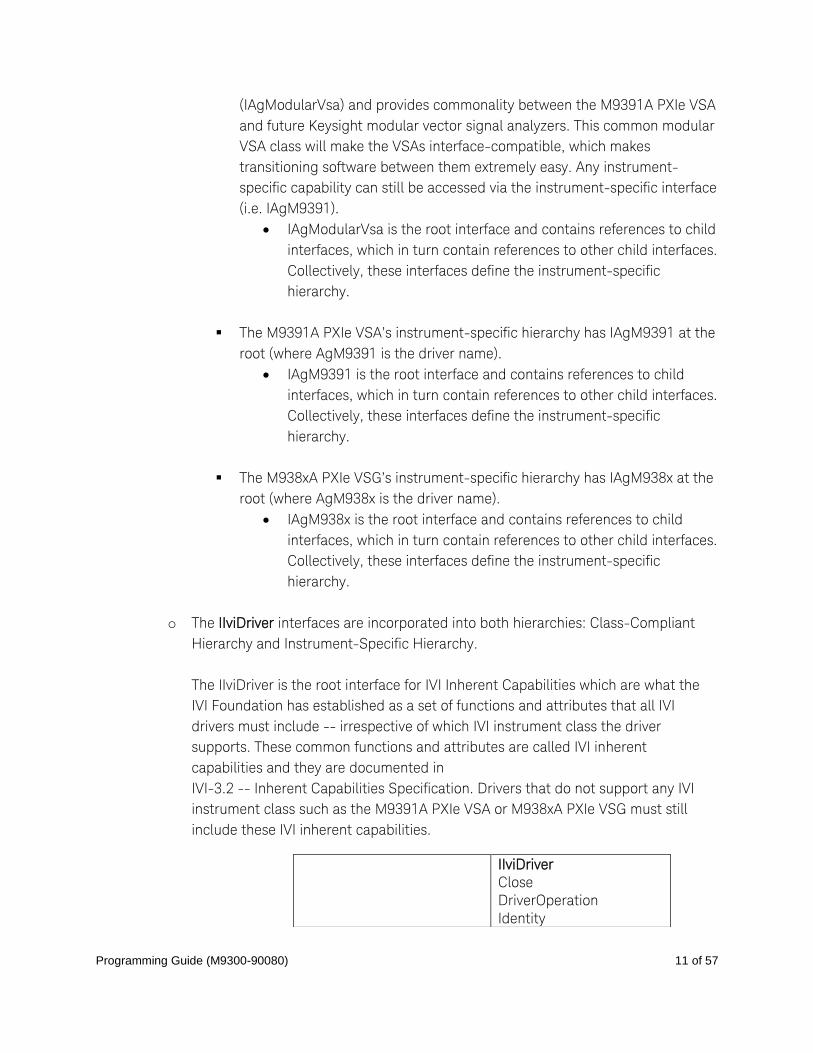
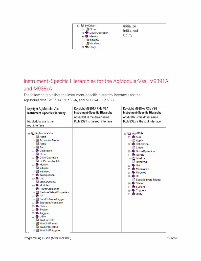
o The IIviDriver interfaces are incorporated into both hierarchies: Class-Compliant
Hierarchy and Instrument-Specific Hierarchy.
The IIviDriver is the root interface for IVI Inherent Capabilities which are what the
IVI Foundation has established as a set of functions and attributes that all IVI
drivers must include -- irrespective of which IVI instrument class the driver
supports. These common functions and attributes are called IVI inherent
capabilities and they are documented in
IVI-3.2 -- Inherent Capabilities Specification. Drivers that do not support any IVI
instrument class such as the M9391A PXIe VSA or M938xA PXIe VSG must still
include these IVI inherent capabilities.
IIviDriver
Close
DriverOperation
Identity
Programming Guide (M9300-90080) 12 of 57
Initialize
Initialized
Utility
Instrument-Specific Hierarchies for the AgModularVsa, M9391A,
and M938xA The following table lists the instrument-specific hierarchy interfaces for the:
AgModularVsa, M9391A PXIe VSA, and M938xA PXIe VSG.
Keysight AgModularVsa Instrument-Specific Hierarchy
Keysight M9391A PXIe VSA
Instrument-Specific Hierarchy
Keysight M938xA PXIe VSG
Instrument-Specific Hierarchy
AgM9391 is the driver name AgM938x is the driver name
IAgModularVsa is the
root interface
IAgM9391 is the root interface IAgM938x is the root interface

Programming Guide (M9300-90080) 13 of 57
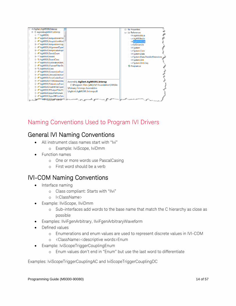
Note:
To view interfaces available in the IAgModularVsa interface, right-click the AgModularVsaLib
library file, in the References folder, from the Solution Explorer window and select View in Object
Browser.
To view the interfaces available in the M9381A PXIe VSG, right-click the AgM938xLib library file, in
the References folder, from the Solution Explorer window and select View in Object Browser.
To view interfaces available in the M9391A PXIe VSAG, right-click the AgM9391Lib library file, in
the References folder, from the Solution Explorer window and select View in Object Browser.
Programming Guide (M9300-90080) 14 of 57
Naming Conventions Used to Program IVI Drivers
General IVI Naming Conventions All instrument class names start with “Ivi”
o Example: IviScope, IviDmm
Function names
o One or more words use PascalCasing
o First word should be a verb
IVI-COM Naming Conventions Interface naming
o Class compliant: Starts with “IIvi”
o I<ClassName>
Example: IIviScope, IIviDmm
o Sub-interfaces add words to the base name that match the C hierarchy as close as
possible
Examples: IIviFgenArbitrary, IIviFgenArbitraryWaveform
Defined values
o Enumerations and enum values are used to represent discrete values in IVI-COM
o <ClassName><descriptive words>Enum
Example: IviScopeTriggerCouplingEnum
o Enum values don’t end in “Enum” but use the last word to differentiate
Examples: IviScopeTriggerCouplingAC and IviScopeTriggerCouplingDC
Programming Guide (M9300-90080) 15 of 57
Tutorial: Create a Project with IVI-COM Using C# This tutorial will walk through the various steps required to create a console application using
Visual Studio and C#. It demonstrates how to instantiate two driver instances, set the resource
names and various initialization values, initialize the two driver instances, print various driver
properties to a console for each driver instance, check drivers for errors and report the errors if
any occur, and close both drivers.
Step 1. - Create a "Console Application"
Step 2. - Add References
Step 3. - Add using Statements
Step 4. - Create an Instance
Step 5. - Initialize the Instance
Step 6. - Write the Program Steps (Create a Signal or Perform a Measurement)
Step 7. - Close the Instance
At the end of this tutorial is a complete example program that shows what the console application
looks like if you follow all of these steps.
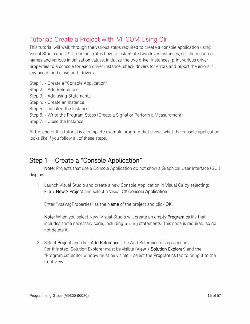
Step 1 – Create a “Console Application” Note: Projects that use a Console Application do not show a Graphical User Interface (GUI)
display.
1. Launch Visual Studio and create a new Console Application in Visual C# by selecting:
File > New > Project and select a Visual C# Console Application.
Enter “VsaVsgProperties” as the Name of the project and click OK.
Note: When you select New, Visual Studio will create an empty Program.cs file that
includes some necessary code, including using statements. This code is required, so do
not delete it.
2. Select Project and click Add Reference. The Add Reference dialog appears.
For this step, Solution Explorer must be visible (View > Solution Explorer) and the
"Program.cs" editor window must be visible – select the Program.cs tab to bring it to the
front view.
Programming Guide (M9300-90080) 16 of 57
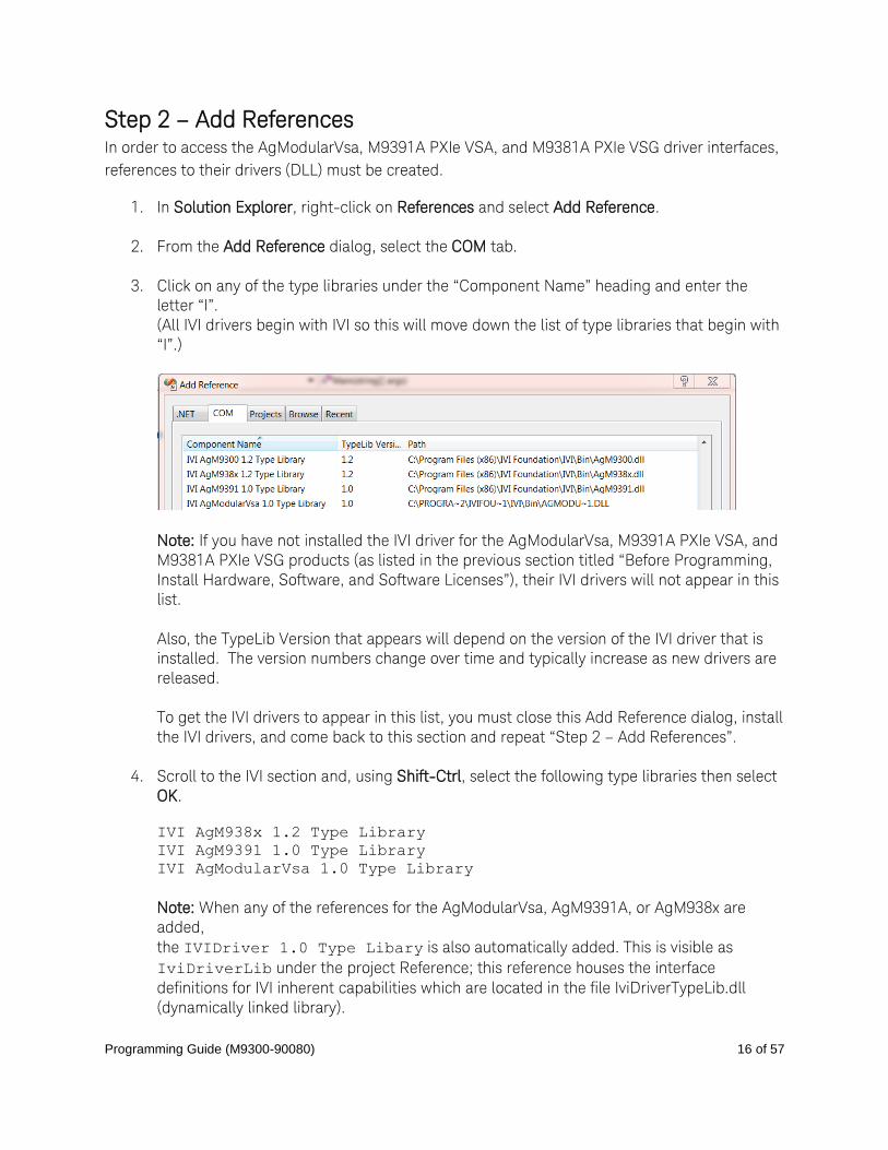
Step 2 – Add References In order to access the AgModularVsa, M9391A PXIe VSA, and M9381A PXIe VSG driver interfaces,
references to their drivers (DLL) must be created.
1. In Solution Explorer, right-click on References and select Add Reference.
2. From the Add Reference dialog, select the COM tab.
3. Click on any of the type libraries under the “Component Name” heading and enter the
letter “I”.
(All IVI drivers begin with IVI so this will move down the list of type libraries that begin with
“I”.)
Note: If you have not installed the IVI driver for the AgModularVsa, M9391A PXIe VSA, and
M9381A PXIe VSG products (as listed in the previous section titled “Before Programming,
Install Hardware, Software, and Software Licenses”), their IVI drivers will not appear in this
list.
Also, the TypeLib Version that appears will depend on the version of the IVI driver that is
installed. The version numbers change over time and typically increase as new drivers are
released.
To get the IVI drivers to appear in this list, you must close this Add Reference dialog, install
the IVI drivers, and come back to this section and repeat “Step 2 – Add References”.
4. Scroll to the IVI section and, using Shift-Ctrl, select the following type libraries then select
OK.
IVI AgM938x 1.2 Type Library
IVI AgM9391 1.0 Type Library
IVI AgModularVsa 1.0 Type Library
Note: When any of the references for the AgModularVsa, AgM9391A, or AgM938x are
added,
the IVIDriver 1.0 Type Libary is also automatically added. This is visible as
IviDriverLib under the project Reference; this reference houses the interface
definitions for IVI inherent capabilities which are located in the file IviDriverTypeLib.dll
(dynamically linked library).
Programming Guide (M9300-90080) 17 of 57
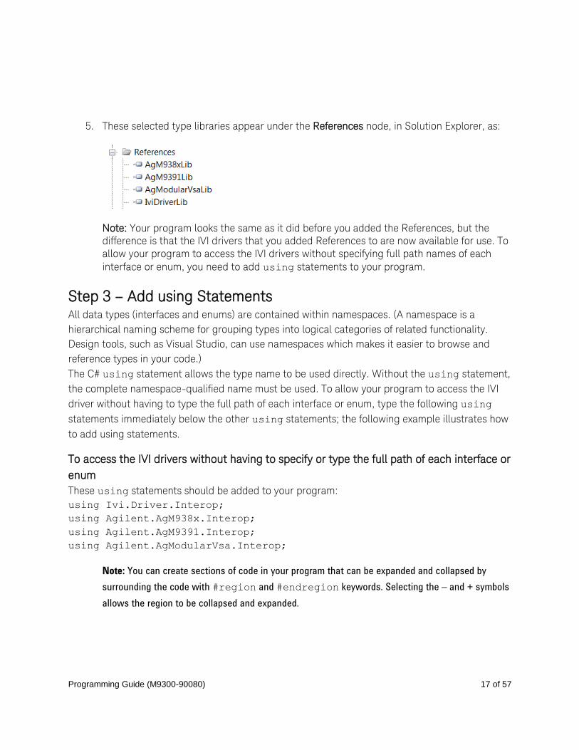
5. These selected type libraries appear under the References node, in Solution Explorer, as:
Note: Your program looks the same as it did before you added the References, but the
difference is that the IVI drivers that you added References to are now available for use. To
allow your program to access the IVI drivers without specifying full path names of each
interface or enum, you need to add using statements to your program.
Step 3 – Add using Statements All data types (interfaces and enums) are contained within namespaces. (A namespace is a
hierarchical naming scheme for grouping types into logical categories of related functionality.
Design tools, such as Visual Studio, can use namespaces which makes it easier to browse and
reference types in your code.)
The C# using statement allows the type name to be used directly. Without the using statement,
the complete namespace-qualified name must be used. To allow your program to access the IVI
driver without having to type the full path of each interface or enum, type the following using
statements immediately below the other using statements; the following example illustrates how
to add using statements.
To access the IVI drivers without having to specify or type the full path of each interface or
enum
These using statements should be added to your program:
using Ivi.Driver.Interop;
using Agilent.AgM938x.Interop;
using Agilent.AgM9391.Interop;
using Agilent.AgModularVsa.Interop;
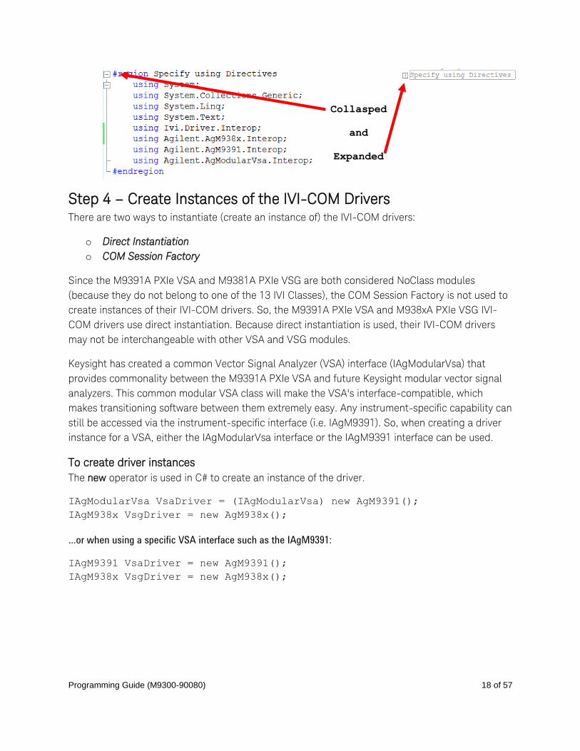
Note: You can create sections of code in your program that can be expanded and collapsed by
surrounding the code with #region and #endregion keywords. Selecting the – and + symbols
allows the region to be collapsed and expanded.
Programming Guide (M9300-90080) 18 of 57
Collasped
and
Expanded
Step 4 – Create Instances of the IVI-COM Drivers There are two ways to instantiate (create an instance of) the IVI-COM drivers:
o Direct Instantiation
o COM Session Factory
Since the M9391A PXIe VSA and M9381A PXIe VSG are both considered NoClass modules
(because they do not belong to one of the 13 IVI Classes), the COM Session Factory is not used to
create instances of their IVI-COM drivers. So, the M9391A PXIe VSA and M938xA PXIe VSG IVI-
COM drivers use direct instantiation. Because direct instantiation is used, their IVI-COM drivers
may not be interchangeable with other VSA and VSG modules.
Keysight has created a common Vector Signal Analyzer (VSA) interface (IAgModularVsa) that
provides commonality between the M9391A PXIe VSA and future Keysight modular vector signal
analyzers. This common modular VSA class will make the VSA's interface-compatible, which
makes transitioning software between them extremely easy. Any instrument-specific capability can
still be accessed via the instrument-specific interface (i.e. IAgM9391). So, when creating a driver
instance for a VSA, either the IAgModularVsa interface or the IAgM9391 interface can be used.
To create driver instances
The new operator is used in C# to create an instance of the driver.
IAgModularVsa VsaDriver = (IAgModularVsa) new AgM9391();
IAgM938x VsgDriver = new AgM938x();
…or when using a specific VSA interface such as the IAgM9391:
IAgM9391 VsaDriver = new AgM9391();
IAgM938x VsgDriver = new AgM938x();
Programming Guide (M9300-90080) 19 of 57
Step 5 – Initialize the Driver Instances Initialize() is required when using any IVI driver; it establishes a communication link (an
"I/O session") with an instrument and it must be called before the program can do anything with
an instrument or work in simulation mode.
The Initialize() method has a number of options that can be defined (see Initialize Options
below).
In this example, we prepare the Initialize() method by defining only a few of the parameters,
then we call the Initialize() method with those parameters:
To determine the VsaResourceName and VsgResourceName
If you are using Simulate Mode, you can set the Resource Name address string to:
string VsaResourceName = “%”;
string VsgResourceName = “%”;
If you are actually establishing a communication link (an "I/O session") with an instrument,
you need to determine the Resource Name address string (VISA address string) that is
needed.
You can use an IO application such as Keysight Connection Expert, Keysight Command
Expert, National Instruments Measurement and Automation Explorer (MAX), or you can use
the Keysight product’s Soft Front Panel (SFP) to get the physical Resource Name string.
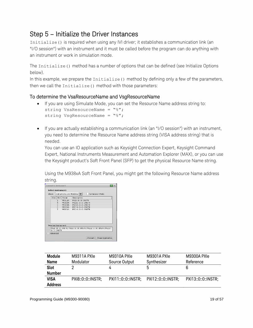
Using the M938xA Soft Front Panel, you might get the following Resource Name address
string.
Module
Name
M9311A PXIe
Modulator
M9310A PXIe
Source Output
M9301A PXIe
Synthesizer
M9300A PXIe
Reference
Slot
Number
2 4 5 6
VISA
Address
PXI8::0::0::INSTR; PXI11::0::0::INSTR; PXI12::0::0::INSTR; PXI13::0::0::INSTR;
Programming Guide (M9300-90080) 20 of 57
string VsgResourceName =
“PXI8::0::0::INSTR;PXI11::0::0::INSTR;PXI12::0::0::INSTR;PXI13::0::0::INSTR
”;
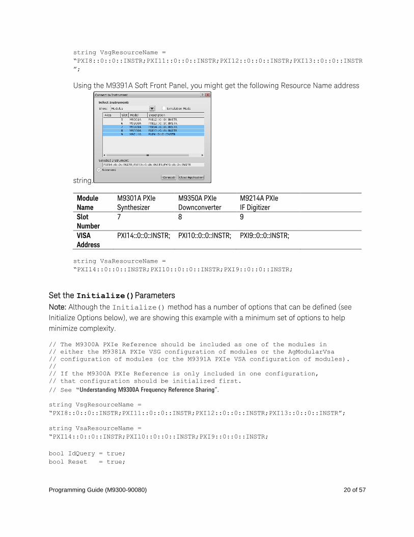
Using the M9391A Soft Front Panel, you might get the following Resource Name address
string.
Module
Name
M9301A PXIe
Synthesizer
M9350A PXIe
Downconverter
M9214A PXIe
IF Digitizer
Slot
Number
7 8 9
VISA
Address
PXI14::0::0::INSTR; PXI10::0::0::INSTR; PXI9::0::0::INSTR;
string VsaResourceName =
“PXI14::0::0::INSTR;PXI10::0::0::INSTR;PXI9::0::0::INSTR;
Set the Initialize()Parameters
Note: Although the Initialize() method has a number of options that can be defined (see
Initialize Options below), we are showing this example with a minimum set of options to help
minimize complexity.
// The M9300A PXIe Reference should be included as one of the modules in
// either the M9381A PXIe VSG configuration of modules or the AgModularVsa
// configuration of modules (or the M9391A PXIe VSA configuration of modules).
//
// If the M9300A PXIe Reference is only included in one configuration,
// that configuration should be initialized first.
// See “Understanding M9300A Frequency Reference Sharing”.
string VsgResourceName =
“PXI8::0::0::INSTR;PXI11::0::0::INSTR;PXI12::0::0::INSTR;PXI13::0::0::INSTR”;
string VsaResourceName =
“PXI14::0::0::INSTR;PXI10::0::0::INSTR;PXI9::0::0::INSTR;
bool IdQuery = true;
bool Reset = true;
Programming Guide (M9300-90080) 21 of 57
string VsgOptionString = "QueryInstrStatus=true, Simulate=false, DriverSetup=
Model=VSG, Trace=false";
string VsaOptionString = "QueryInstrStatus=true, Simulate=false, DriverSetup=
Model=VSA, Trace=false";
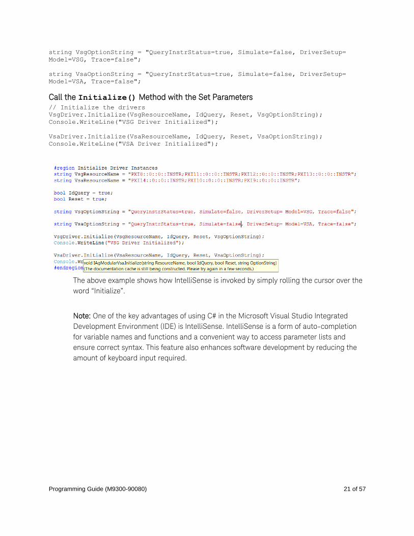
Call the Initialize() Method with the Set Parameters // Initialize the drivers
VsgDriver.Initialize(VsgResourceName, IdQuery, Reset, VsgOptionString);
Console.WriteLine("VSG Driver Initialized");
VsaDriver.Initialize(VsaResourceName, IdQuery, Reset, VsaOptionString);
Console.WriteLine("VSA Driver Initialized");
The above example shows how IntelliSense is invoked by simply rolling the cursor over the
word “Initialize”.
Note: One of the key advantages of using C# in the Microsoft Visual Studio Integrated
Development Environment (IDE) is IntelliSense. IntelliSense is a form of auto-completion
for variable names and functions and a convenient way to access parameter lists and
ensure correct syntax. This feature also enhances software development by reducing the
amount of keyboard input required.

Programming Guide (M9300-90080) 22 of 57
Understanding Initialize Options
The following table describes options that are most commonly used with the Initialize()
method.
Property Type and Example Value
Description of Property
string ResourceName =
PXI[bus]::device[::function][::INSTR]
string ResourceName = “PXI13::0::0::INSTR;
PXI14::0::0::INSTR;
PXI15::0::0::INSTR;
PXI16::0::0::INSTR”;
VsgResourceName or VsaResourceName – The
driver is typically initialized using a physical
resource name descriptor, often a VISA resource
descriptor.
See the above procedure:
“To determine the VsgResourceName and
VsaResourceName”
bool IdQuery = true;
IdQuery - Setting the ID query to false prevents
the driver from verifying that the connected
instrument is the one the driver was written for
because if IdQuery is set to true, this will query the
instrument model and fail initialization if the model
is not supported by the driver.
bool Reset = true;
Reset - Setting Reset to true tells the driver to
initially reset the instrument.
string OptionString = "QueryInstrStatus=true,
Simulate=true,
OptionString - Setup the following initialization
options:
o QueryInstrStatus=true (Specifies whether the
IVI specific driver queries the instrument
status at the end of each user operation.)
o Simulate=true (Setting Simulate to true tells
the driver that it should not attempt to
connect to a physical instrument, but use a
simulation of the instrument instead.) o Cache=false (Specifies whether or not to
cache the value of properties.)
o InterchangeCheck=false (Specifies whether
the IVI specific driver performs
interchangeability checking.)
o RangeCheck=false (Specifies whether the IVI
specific driver validates attribute values and
function parameters.)
o RecordCoercions=false (Specifies whether the
IVI specific driver keeps a list of the value
coercions it makes for ViInt32 and ViReal64
attributes.)

Programming Guide (M9300-90080) 23 of 57
DriverSetup= Trace=false";
o DriverSetup= (This is used to specify settings
that are supported by the driver, but not
defined by IVI. If the Options String parameter
(OptionString in this example) contains an
assignment for the Driver Setup attribute, the
Initialize function assumes that everything
following 'DriverSetup=' is part of the
assignment.) o Model=VSG or Model=VSA (Instrument model
to use during simulation.)
o Trace=false (If false, an output trace log of all
driver calls is not saved in an XML file.)
If these drivers were installed, additional information can be found under “Initializing the IVI-COM
Driver” from the following:
AgM938x IVI Driver Reference
Start > All Programs > Keysight IVI Drivers > AgM938x Source > Documentation
AgM9391 IVI Driver Reference
Start > All Programs > Keysight IVI Drivers > AgM9391A VSA > Documentation

Programming Guide (M9300-90080) 24 of 57
Understanding M9300A Reference Sharing
The M9300A PXIe Reference can be shared by up to five configurations of modules that can be
made up of the M9391A PXIe VSA or the M9381A PXIe VSG or both. The M9300A PXIe Reference
must be included as one of the modules in at least one of these configurations. The configuration
of modules that is initialized first must include the M9300A PXIe Reference so that the other
configurations that depend on the reference signal get the signal they are expecting. If the
configuration of modules that is initialized first does not include the M9300A PXIe Reference,
unlock errors will occur.
Example: M9300A PXIe Reference as Part of the M9381A PXIe VSG Configuration of Modules
The M9381A PXIe VSG should be initialized first before initializing the VSA if:
M9381A PXIe VSG configuration of modules includes:
o M9311A PXIe Modulator
o M9310A PXIe Source Output
o M9301A PXIe Synthesizer
o M9300A PXIe Reference // Note that the M9300A PXIe Reference is part of the M9381A PXIe
VSG configuration of modules.
string VsgResourceName =
“PXI8::0::0::INSTR;PXI11::0::0::INSTR;PXI12::0::0::INSTR;PXI13::0::0:
:INSTR”;
M9391A PXIe VSA configuration of modules includes:
o M9301A PXIe Synthesizer
o M9350A PXIe Downconverter
o M9214A PXIe IF Digitizer
string VsaResourceName =
“PXI14::0::0::INSTR;PXI10::0::0::INSTR;PXI9::0::0::INSTR”;
Example: M9300A PXIe Reference as Part of the M9391A PXIe VSA Configuration of Modules
The M9391A PXIe VSA should be initialized first before initializing the M9381A PXIe VSG if:
M9381A PXIe VSG configuration of modules includes:
o M9311A PXIe Modulator
o M9310A PXIe Source Output
o M9301A PXIe Synthesizer
string VsgResourceName =
“PXI8::0::0::INSTR;PXI11::0::0::INSTR;PXI12::0::0::INSTR”;
M9391A PXIe VSA configuration of modules includes:
Programming Guide (M9300-90080) 25 of 57
o M9300A PXIe Reference // Note that the M9300A PXIe Reference is part of the M9391A PXIe
VSA configuration of modules.
o M9301A PXIe Synthesizer
o M9350A PXIe Downconverter
o M9214A PXIe IF Digitizer
string VsaResourceName =
“PXI14::0::0::INSTR;PXI10::0::0::INSTR;PXI9::0::0::INSTR;PXI13::0::0:
:INSTR;
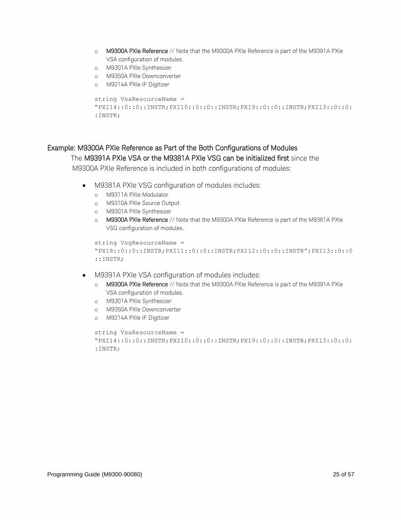
Example: M9300A PXIe Reference as Part of the Both Configurations of Modules
The M9391A PXIe VSA or the M9381A PXIe VSG can be initialized first since the
M9300A PXIe Reference is included in both configurations of modules:
M9381A PXIe VSG configuration of modules includes:
o M9311A PXIe Modulator
o M9310A PXIe Source Output
o M9301A PXIe Synthesizer
o M9300A PXIe Reference // Note that the M9300A PXIe Reference is part of the M9381A PXIe
VSG configuration of modules.
string VsgResourceName =
“PXI8::0::0::INSTR;PXI11::0::0::INSTR;PXI12::0::0::INSTR”;PXI13::0::0
::INSTR;
M9391A PXIe VSA configuration of modules includes:
o M9300A PXIe Reference // Note that the M9300A PXIe Reference is part of the M9391A PXIe
VSA configuration of modules.
o M9301A PXIe Synthesizer
o M9350A PXIe Downconverter
o M9214A PXIe IF Digitizer
string VsaResourceName =
“PXI14::0::0::INSTR;PXI10::0::0::INSTR;PXI9::0::0::INSTR;PXI13::0::0:
:INSTR;
Programming Guide (M9300-90080) 26 of 57
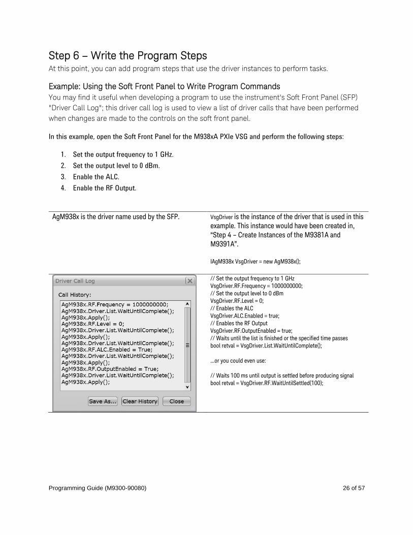
Step 6 – Write the Program Steps At this point, you can add program steps that use the driver instances to perform tasks.
Example: Using the Soft Front Panel to Write Program Commands
You may find it useful when developing a program to use the instrument's Soft Front Panel (SFP)
"Driver Call Log"; this driver call log is used to view a list of driver calls that have been performed
when changes are made to the controls on the soft front panel.
In this example, open the Soft Front Panel for the M938xA PXIe VSG and perform the following steps:
1. Set the output frequency to 1 GHz.
2. Set the output level to 0 dBm.
3. Enable the ALC.
4. Enable the RF Output.
AgM938x is the driver name used by the SFP. VsgDriver is the instance of the driver that is used in this
example. This instance would have been created in,
“Step 4 – Create Instances of the M9381A and
M9391A”.
IAgM938x VsgDriver = new AgM938x();
// Set the output frequency to 1 GHz
VsgDriver.RF.Frequency = 1000000000;
// Set the output level to 0 dBm
VsgDriver.RF.Level = 0;
// Enables the ALC
VsgDriver.ALC.Enabled = true;
// Enables the RF Output
VsgDriver.RF.OutputEnabled = true;
// Waits until the list is finished or the specified time passes
bool retval = VsgDriver.List.WaitUntilComplete();
…or you could even use:
// Waits 100 ms until output is settled before producing signal
bool retval = VsgDriver.RF.WaitUntilSettled(100);
Programming Guide (M9300-90080) 27 of 57
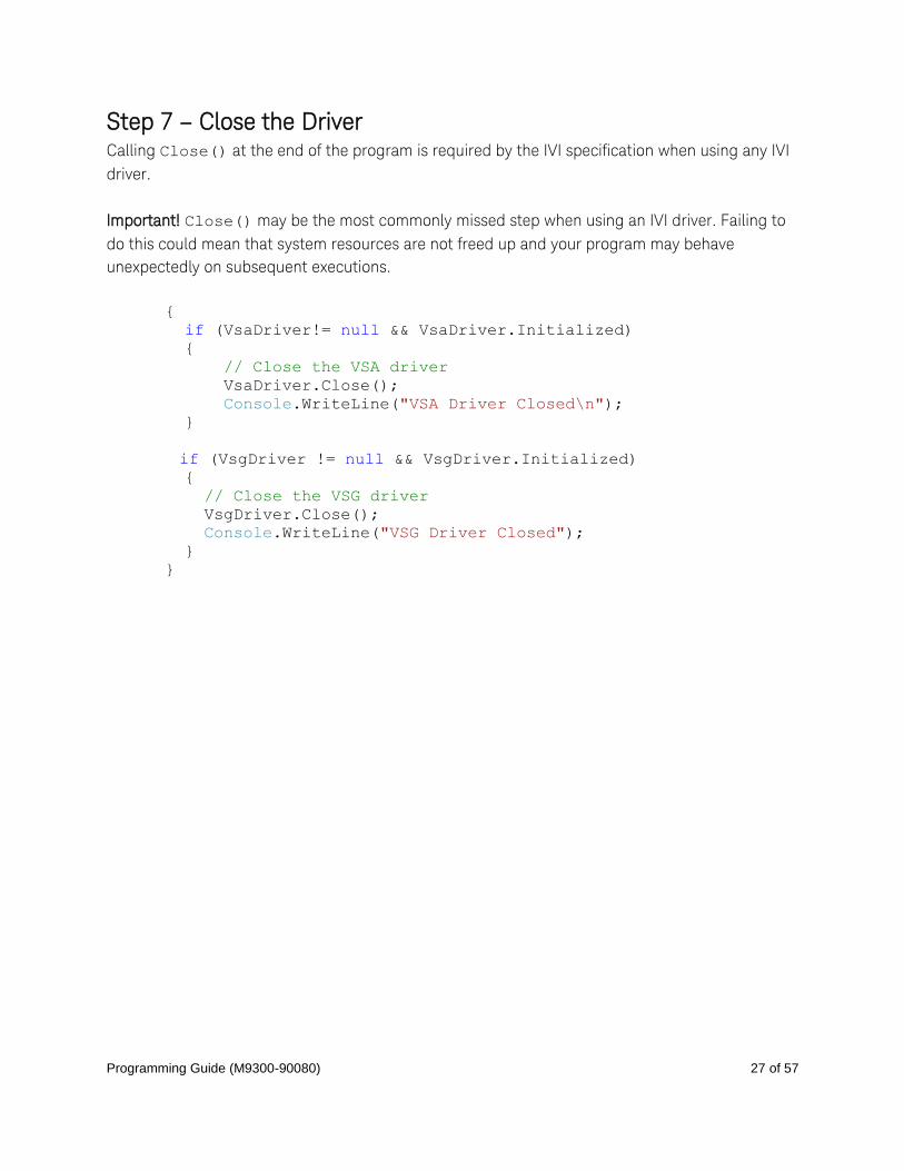
Step 7 – Close the Driver Calling Close() at the end of the program is required by the IVI specification when using any IVI
driver.
Important! Close() may be the most commonly missed step when using an IVI driver. Failing to
do this could mean that system resources are not freed up and your program may behave
unexpectedly on subsequent executions.
{
if (VsaDriver!= null && VsaDriver.Initialized)
{
// Close the VSA driver
VsaDriver.Close();
Console.WriteLine("VSA Driver Closed\n");
}
if (VsgDriver != null && VsgDriver.Initialized)
{
// Close the VSG driver
VsgDriver.Close();
Console.WriteLine("VSG Driver Closed");
}
}
Programming Guide (M9300-90080) 28 of 57
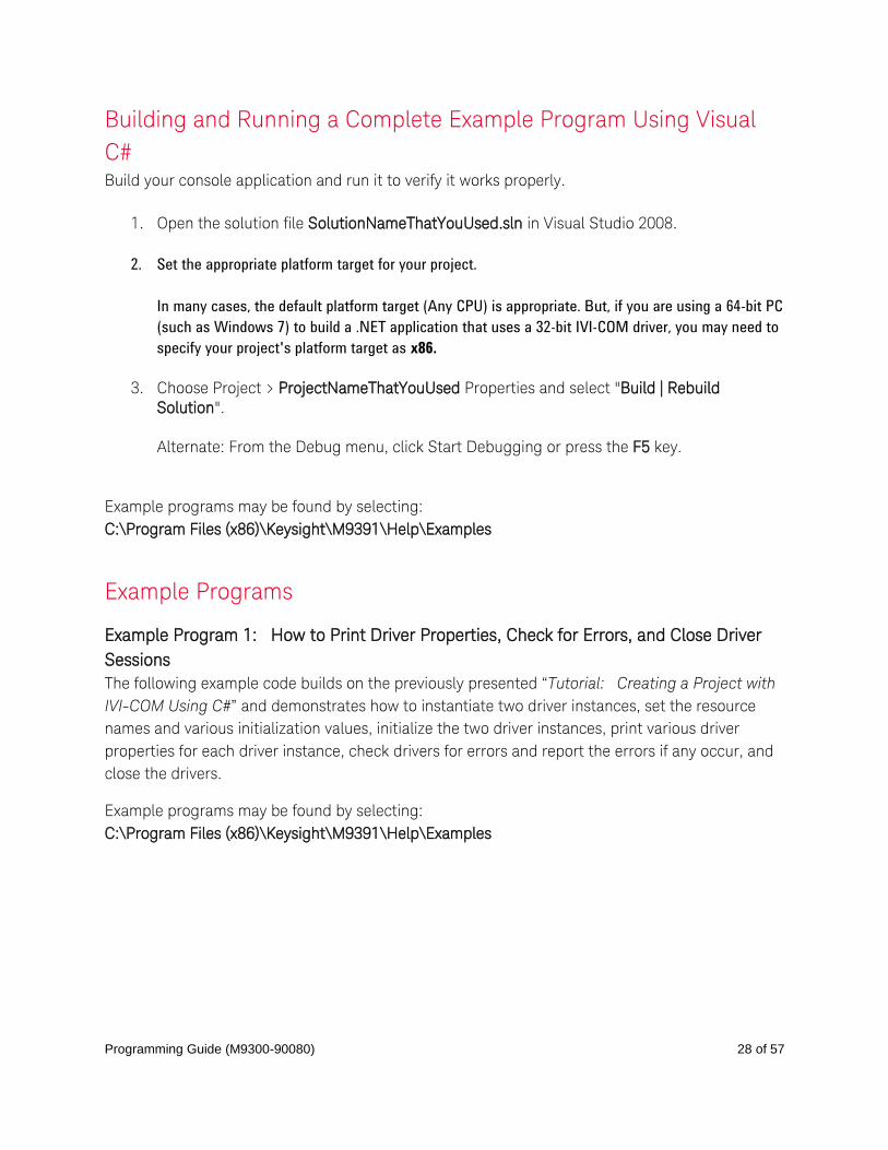
Building and Running a Complete Example Program Using Visual
C# Build your console application and run it to verify it works properly.
1. Open the solution file SolutionNameThatYouUsed.sln in Visual Studio 2008.
2. Set the appropriate platform target for your project.
In many cases, the default platform target (Any CPU) is appropriate. But, if you are using a 64-bit PC
(such as Windows 7) to build a .NET application that uses a 32-bit IVI-COM driver, you may need to
specify your project's platform target as x86.
3. Choose Project > ProjectNameThatYouUsed Properties and select "Build | Rebuild
Solution".
Alternate: From the Debug menu, click Start Debugging or press the F5 key.
Example programs may be found by selecting:
C:\Program Files (x86)\Keysight\M9391\Help\Examples
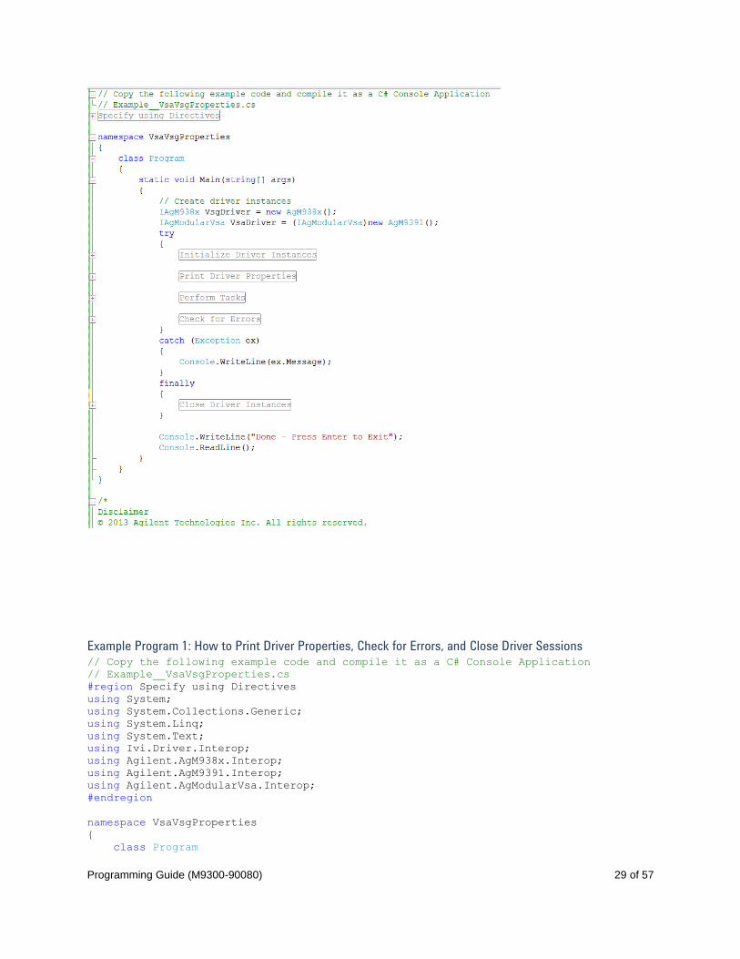
Example Programs
Example Program 1: How to Print Driver Properties, Check for Errors, and Close Driver
Sessions
The following example code builds on the previously presented “Tutorial: Creating a Project with
IVI-COM Using C#” and demonstrates how to instantiate two driver instances, set the resource
names and various initialization values, initialize the two driver instances, print various driver
properties for each driver instance, check drivers for errors and report the errors if any occur, and
close the drivers.
Example programs may be found by selecting:
C:\Program Files (x86)\Keysight\M9391\Help\Examples
Programming Guide (M9300-90080) 29 of 57
Example Program 1: How to Print Driver Properties, Check for Errors, and Close Driver Sessions // Copy the following example code and compile it as a C# Console Application
// Example__VsaVsgProperties.cs
#region Specify using Directives
using System;
using System.Collections.Generic;
using System.Linq;
using System.Text;
using Ivi.Driver.Interop;
using Agilent.AgM938x.Interop;
using Agilent.AgM9391.Interop;
using Agilent.AgModularVsa.Interop;
#endregion
namespace VsaVsgProperties
{
class Program
Programming Guide (M9300-90080) 30 of 57
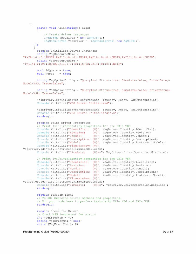
{
static void Main(string[] args)
{
// Create driver instances
IAgM938x VsgDriver = new AgM938x();
IAgModularVsa VsaDriver = (IAgModularVsa) new AgM9391();
try
{
#region Initialize Driver Instances
string VsgResourceName =
"PXI8::0::0::INSTR;PXI11::0::0::INSTR;PXI12::0::0::INSTR;PXI13::0::0::INSTR";
string VsaResourceName =
"PXI14::0::0::INSTR;PXI10::0::0::INSTR;PXI9::0::0::INSTR";
bool IdQuery = true;
bool Reset = true;
string VsgOptionString = "QueryInstrStatus=true, Simulate=false, DriverSetup=
Model=VSG, Trace=false";
string VsaOptionString = "QueryInstrStatus=true, Simulate=false, DriverSetup=
Model=VSA, Trace=false";
VsgDriver.Initialize(VsgResourceName, IdQuery, Reset, VsgOptionString);
Console.WriteLine("VSG Driver Initialized");
VsaDriver.Initialize(VsaResourceName, IdQuery, Reset, VsaOptionString);
Console.WriteLine("VSA Driver Initialized\n\n");
#endregion
#region Print Driver Properties
// Print IviDriverIdentity properties for the PXIe VSG
Console.WriteLine("Identifier: {0}", VsgDriver.Identity.Identifier);
Console.WriteLine("Revision: {0}", VsgDriver.Identity.Revision);
Console.WriteLine("Vendor: {0}", VsgDriver.Identity.Vendor);
Console.WriteLine("Description: {0}", VsgDriver.Identity.Description);
Console.WriteLine("Model: {0}", VsgDriver.Identity.InstrumentModel);
Console.WriteLine("FirmwareRev: {0}",
VsgDriver.Identity.InstrumentFirmwareRevision);
Console.WriteLine("Simulate: {0}\n", VsgDriver.DriverOperation.Simulate);
// Print IviDriverIdentity properties for the PXIe VSA
Console.WriteLine("Identifier: {0}", VsaDriver.Identity.Identifier);
Console.WriteLine("Revision: {0}", VsaDriver.Identity.Revision);
Console.WriteLine("Vendor: {0}", VsaDriver.Identity.Vendor);
Console.WriteLine("Description: {0}", VsaDriver.Identity.Description);
Console.WriteLine("Model: {0}", VsaDriver.Identity.InstrumentModel);
Console.WriteLine("FirmwareRev: {0}",
VsaDriver.Identity.InstrumentFirmwareRevision);
Console.WriteLine("Simulate: {0}\n", VsaDriver.DriverOperation.Simulate);
#endregion
#region Perform Tasks
// TO DO: Exercise driver methods and properties.
// Put your code here to perform tasks with PXIe VSG and PXIe VSA.
#endregion
#region Check for Errors
// Check VSG instrument for errors
int VsgErrorNum = -1;
string VsgErrorMsg = null;
while (VsgErrorNum != 0)
Programming Guide (M9300-90080) 31 of 57
{
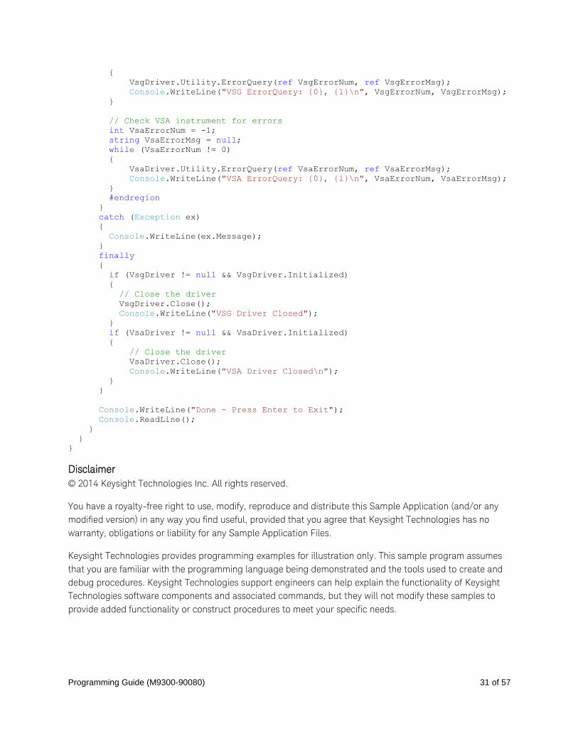
VsgDriver.Utility.ErrorQuery(ref VsgErrorNum, ref VsgErrorMsg);
Console.WriteLine("VSG ErrorQuery: {0}, {1}\n", VsgErrorNum, VsgErrorMsg);
}
// Check VSA instrument for errors
int VsaErrorNum = -1;
string VsaErrorMsg = null;
while (VsaErrorNum != 0)
{
VsaDriver.Utility.ErrorQuery(ref VsaErrorNum, ref VsaErrorMsg);
Console.WriteLine("VSA ErrorQuery: {0}, {1}\n", VsaErrorNum, VsaErrorMsg);
}
#endregion
}
catch (Exception ex)
{
Console.WriteLine(ex.Message);
}
finally
{
if (VsgDriver != null && VsgDriver.Initialized)
{
// Close the driver
VsgDriver.Close();
Console.WriteLine("VSG Driver Closed");
}
if (VsaDriver != null && VsaDriver.Initialized)
{
// Close the driver
VsaDriver.Close();
Console.WriteLine("VSA Driver Closed\n");
}
}
Console.WriteLine("Done - Press Enter to Exit");
Console.ReadLine();
}
}
}
Disclaimer
© 2014 Keysight Technologies Inc. All rights reserved.
You have a royalty-free right to use, modify, reproduce and distribute this Sample Application (and/or any
modified version) in any way you find useful, provided that you agree that Keysight Technologies has no
warranty, obligations or liability for any Sample Application Files.
Keysight Technologies provides programming examples for illustration only. This sample program assumes
that you are familiar with the programming language being demonstrated and the tools used to create and
debug procedures. Keysight Technologies support engineers can help explain the functionality of Keysight
Technologies software components and associated commands, but they will not modify these samples to
provide added functionality or construct procedures to meet your specific needs.

Programming Guide (M9300-90080) 32 of 57
Alternate Example Program 1: How to Print Driver Properties, Check for Errors, and Close Driver Sessions
The following example program is an alternative way of performing the same tasks as the previous
Example Program 1, but uses the IAgM9391 interface instead of the IAgModularVsa interface.
When comparing this example program to Example Program 1, you should note that it does not
include the using Agilent.AgModularVsa.Interop; and also does not have to have the IVI
AgModularVsa 1.0 Type Library reference added. By using the IAgM9391 interface along
with the driver instance variable M9391driver, this code would have to be updated to be used with
a different future VSA module.
// Copy the following example code and compile it as a C# Console Application
// Example__VsaVsgProperties__Alternate.cs
Programming Guide (M9300-90080) 33 of 57
#region Specify using Directives
using System;
using System.Collections.Generic;
using System.Linq;
using System.Text;
using Ivi.Driver.Interop;
using Agilent.AgM938x.Interop;
using Agilent.AgM9391.Interop;
#endregion
namespace M9381_M9391_ConsoleApp_Properties
{
class Program
{
static void Main(string[] args)
{
// Create driver instances
IAgM938x M9381driver = new AgM938x();
IAgM9391 M9391driver = new AgM9391();
try
{
#region Initialize Driver Instances
string M9381ResourceName =
"PXI8::0::0::INSTR;PXI11::0::0::INSTR;PXI12::0::0::INSTR;PXI13::0::0::INSTR";
string M9391ResourceName =
"PXI14::0::0::INSTR;PXI10::0::0::INSTR;PXI9::0::0::INSTR";
bool IdQuery = true;
bool Reset = true;
string M9381OptionString = "QueryInstrStatus=true, Simulate=false,
DriverSetup= Model=M9381A, Trace=false";
string M9391OptionString = "QueryInstrStatus=true, Simulate=false,
DriverSetup= Model=M9391A, Trace=false";
M9381driver.Initialize(M9381ResourceName, IdQuery, Reset, M9381OptionString);
Console.WriteLine("M9381A Driver Initialized");
M9391driver.Initialize(M9391ResourceName, IdQuery, Reset, M9391OptionString);
Console.WriteLine("M9391A Driver Initialized\n\n");
#endregion
#region Print Driver Properties
// Print IviDriverIdentity properties for the M9381A PXIe VSG
Console.WriteLine("Identifier: {0}", M9381driver.Identity.Identifier);
Console.WriteLine("Revision: {0}", M9381driver.Identity.Revision);
Console.WriteLine("Vendor: {0}", M9381driver.Identity.Vendor);
Console.WriteLine("Description: {0}", M9381driver.Identity.Description);
Console.WriteLine("Model: {0}", M9381driver.Identity.InstrumentModel);
Console.WriteLine("FirmwareRev: {0}",
M9381driver.Identity.InstrumentFirmwareRevision);
Console.WriteLine("Simulate: {0}\n", M9381driver.DriverOperation.Simulate);
// Print IviDriverIdentity properties for the M9391A PXIe VSA
Console.WriteLine("Identifier: {0}", M9391driver.Identity.Identifier);
Console.WriteLine("Revision: {0}", M9391driver.Identity.Revision);
Console.WriteLine("Vendor: {0}", M9391driver.Identity.Vendor);
Console.WriteLine("Description: {0}", M9391driver.Identity.Description);
Console.WriteLine("Model: {0}", M9391driver.Identity.InstrumentModel);
Console.WriteLine("FirmwareRev: {0}",
M9391driver.Identity.InstrumentFirmwareRevision);
Programming Guide (M9300-90080) 34 of 57
Console.WriteLine("Simulate: {0}\n", M9391driver.DriverOperation.Simulate);
#endregion
#region Perform Tasks
// TO DO: Exercise driver methods and properties.
// Put your code here to perform tasks w/ M9381A PXIe VSG and M9391A PXIe VSA.
#endregion
#region Check for Errors
// Check M9381A instrument for errors
int M9381errorNum = -1;
string M9381errorMsg = null;
while (M9381errorNum != 0)
{
M9381driver.Utility.ErrorQuery(ref M9381errorNum, ref M9381errorMsg);
Console.WriteLine("M9381A ErrorQuery: {0}, {1}\n", M9381errorNum,
M9381errorMsg);
}
// Check M9391A instrument for errors
int M9391errorNum = -1;
string M9391errorMsg = null;
while (M9391errorNum != 0)
{
M9391driver.Utility.ErrorQuery(ref M9391errorNum, ref M9391errorMsg);
Console.WriteLine("M9391A ErrorQuery: {0}, {1}\n", M9391errorNum,
M9391errorMsg);
}
#endregion
}
catch (Exception ex)
{
Console.WriteLine(ex.Message);
}
finally
{
if (M9381driver != null && M9381driver.Initialized)
{
// Close the driver
M9381driver.Close();
Console.WriteLine("M9381A Driver Closed");
}
if (M9391driver != null && M9391driver.Initialized)
{
// Close the driver
M9391driver.Close();
Console.WriteLine("M9391A Driver Closed\n");
}
}
Console.WriteLine("Done - Press Enter to Exit");
Console.ReadLine();
}
}
}
Disclaimer
© 2014 Keysight Technologies Inc. All rights reserved.
You have a royalty-free right to use, modify, reproduce and distribute this Sample Application (and/or any

Programming Guide (M9300-90080) 35 of 57
modified version) in any way you find useful, provided that you agree that Keysight Technologies has no
warranty, obligations or liability for any Sample Application Files.
Keysight Technologies provides programming examples for illustration only. This sample program assumes
that you are familiar with the programming language being demonstrated and the tools used to create and
debug procedures. Keysight Technologies support engineers can help explain the functionality of Keysight
Technologies software components and associated commands, but they will not modify these samples to
provide added functionality or construct procedures to meet your specific needs.

Programming Guide (M9300-90080) 36 of 57
Understanding PA / FEM Measurements The RF front end of a product includes all of the components between an antenna and the
baseband device and the purpose of an RF front end semiconductor is to upconvert a baseband
signal to RF that can be used for transmission by an antenna. It can also be used to downconvert
an RF signal that can be processed with ADC circuitry. As an example, the RF signal that is
received by a cellular phone is the input into the front end circuitry and the output is a down-
converted analog signal in the intermediate frequency (IF) range. The down-converted signal is
the input to a baseband device, an ADC. For the transmit side, a DAC generates the signal to be
up-converted, amplified, and sent to the antenna for transmission. Depending on whether the
system is a Wi-Fi, GPS, or cellular radio will require different characteristics of the front end
devices.
RF front end devices fall into a few major categories: RF Power Amplifiers, RF Filters and Switches,
and FEMs [Front End Modules].
RF Power Amplifiers and RF Filters and Switches typically require the following:
o PA [Power Amplifier] – Production Tests include:
Channel Power - Power Acquisition Mode is used to return one value back
through the API.
ACPR [Adjacent Channel Power Ratio] – When making fast ACPR
measurements, "Baseband Tuning" is used to digitally tune the center
frequency in order to make channel power measurements, at multiple
offsets, using the Power Acquisition interface.
Servo Loop - When measuring a power amplifier, one of the key
measurements is performing a Servo Loop because when you measure a
power amplifier:
it is typically specified at a specific output power
there is a need to adjust the source input level until you measure
the exact power level - to do this, you will continually adjust the
source until you achieve the specified output power then you make
all of the ACPR and harmonics parametric measurements at that
level.
FEMs [Front End Modules] – which could be a combination of multiple front end functions
in a single module or even a "Switch Matrix" that switches various radios (such as Wi-Fi,
GSM, PCS, Bluetooth, etc.) to the antenna.
Programming Guide (M9300-90080) 37 of 57
Test Challenges Faced by Power Amplifier Testing The need to quickly adjust power level inputs to the device under test (DUT).
The need to assess modulation performance (i.e., ACPR and EVM) at high output power levels.
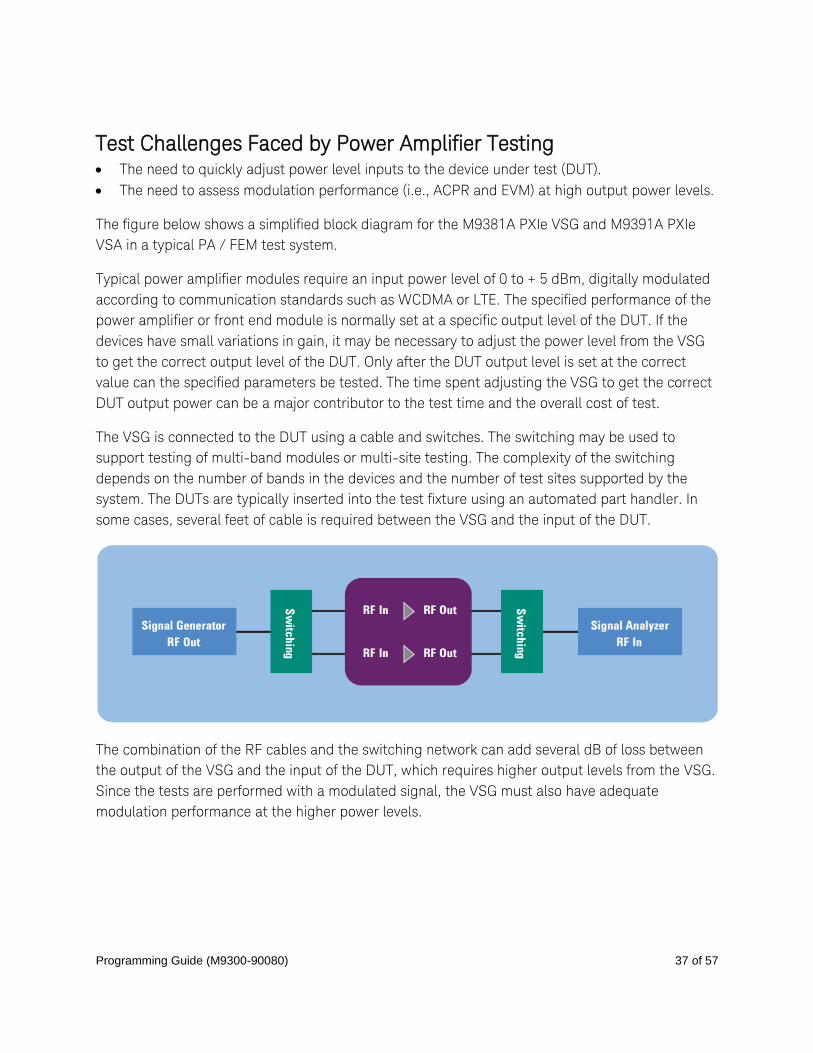
The figure below shows a simplified block diagram for the M9381A PXIe VSG and M9391A PXIe
VSA in a typical PA / FEM test system.
Typical power amplifier modules require an input power level of 0 to + 5 dBm, digitally modulated
according to communication standards such as WCDMA or LTE. The specified performance of the
power amplifier or front end module is normally set at a specific output level of the DUT. If the
devices have small variations in gain, it may be necessary to adjust the power level from the VSG
to get the correct output level of the DUT. Only after the DUT output level is set at the correct
value can the specified parameters be tested. The time spent adjusting the VSG to get the correct
DUT output power can be a major contributor to the test time and the overall cost of test.
The VSG is connected to the DUT using a cable and switches. The switching may be used to
support testing of multi-band modules or multi-site testing. The complexity of the switching
depends on the number of bands in the devices and the number of test sites supported by the
system. The DUTs are typically inserted into the test fixture using an automated part handler. In
some cases, several feet of cable is required between the VSG and the input of the DUT.
The combination of the RF cables and the switching network can add several dB of loss between
the output of the VSG and the input of the DUT, which requires higher output levels from the VSG.
Since the tests are performed with a modulated signal, the VSG must also have adequate
modulation performance at the higher power levels.
Programming Guide (M9300-90080) 38 of 57
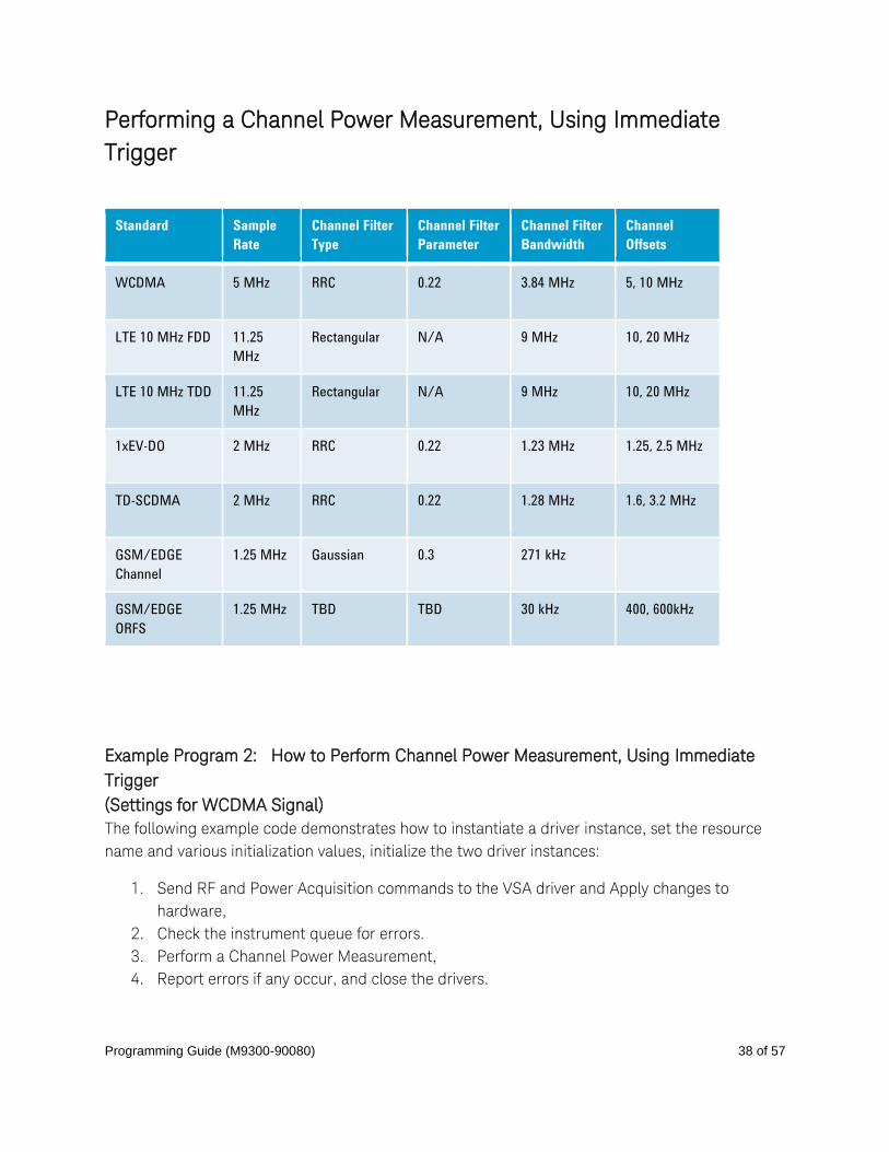
Performing a Channel Power Measurement, Using Immediate
Trigger
Standard Sample
Rate
Channel Filter
Type
Channel Filter
Parameter
Channel Filter
Bandwidth
Channel
Offsets
WCDMA 5 MHz RRC 0.22 3.84 MHz 5, 10 MHz
LTE 10 MHz FDD 11.25
MHz
Rectangular N/A 9 MHz 10, 20 MHz
LTE 10 MHz TDD 11.25
MHz
Rectangular N/A 9 MHz 10, 20 MHz
1xEV-DO 2 MHz RRC 0.22 1.23 MHz 1.25, 2.5 MHz
TD-SCDMA 2 MHz RRC 0.22 1.28 MHz 1.6, 3.2 MHz
GSM/EDGE
Channel
1.25 MHz Gaussian 0.3 271 kHz
GSM/EDGE
ORFS
1.25 MHz TBD TBD 30 kHz 400, 600kHz
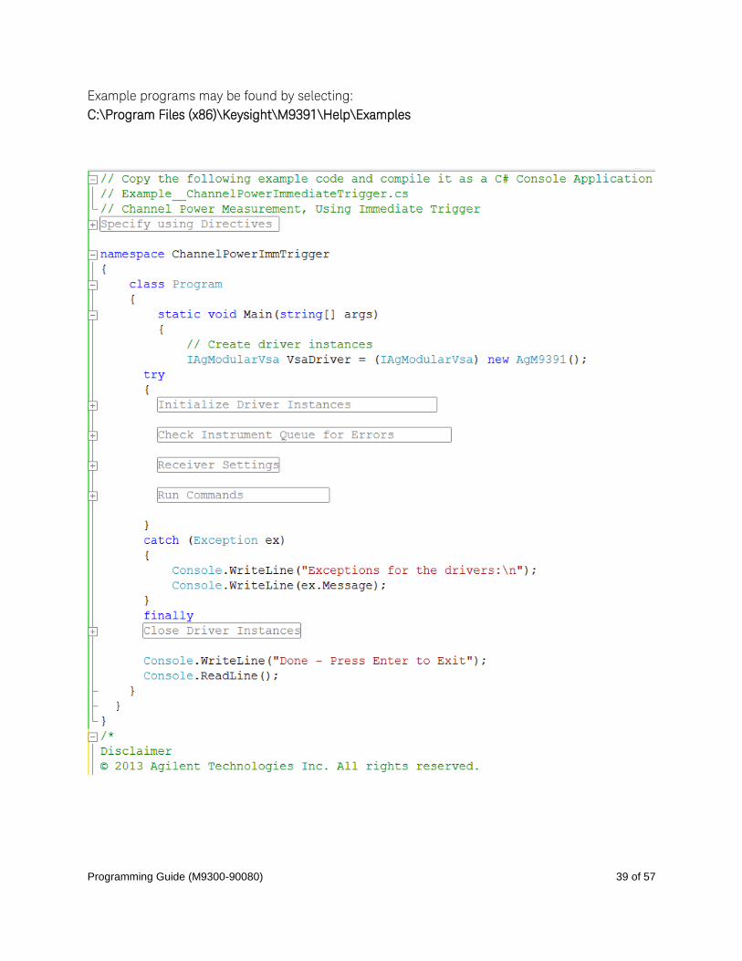
Example Program 2: How to Perform Channel Power Measurement, Using Immediate
Trigger
(Settings for WCDMA Signal)
The following example code demonstrates how to instantiate a driver instance, set the resource
name and various initialization values, initialize the two driver instances:
1. Send RF and Power Acquisition commands to the VSA driver and Apply changes to
hardware,
2. Check the instrument queue for errors.
3. Perform a Channel Power Measurement,
4. Report errors if any occur, and close the drivers.
Programming Guide (M9300-90080) 39 of 57
Example programs may be found by selecting:
C:\Program Files (x86)\Keysight\M9391\Help\Examples

Programming Guide (M9300-90080) 40 of 57
Pseudo-code of How to Perform Channel Power Measurement, Using Immediate Trigger
Initialize Driver for VSA, Check for Errors
Send RF Settings to VSA Driver:
o Frequency
o Level
o Peak to Average Ratio
o Conversion Mode
o IF Bandwidth
o Set Acquisition Mode to “Power”
Send Power Acquisition Setting to VSA Driver:
o Sample Rate
o Duration
o Channel Filter
Apply Method to Send Changes to Hardware
o Wait for Hardware to Settle
Send Arm Method to VSA
Send Read Power Method to VSA
Close Driver for VSA
Example Program 2: How to Perform Channel Power Measurement, Using Immediate Trigger // Copy the following example code and compile it as a C# Console Application
// Example__ChannelPowerImmediateTrigger.cs
#region Specify using Directives
using System;
using System.Collections.Generic;
using System.Linq;
using System.Text;
using Ivi.Driver.Interop;
using Agilent.AgM9391.Interop;
using Agilent.AgModularVsa.Interop;
#endregion
namespace ChannelPowerImmTrigger
{
class Program
{
static void Main(string[] args)
{
// Create driver instances
IAgModularVsa VsaDriver = (IAgModularVsa) new AgM9391();
try
{
#region Initialize Driver Instances
string VSAResourceName =
"PXI14::0::0::INSTR;PXI10::0::0::INSTR;PXI9::0::0::INSTR;PXI13::0::0::INSTR";
bool IdQuery = true;
bool Reset = true;
string VSAOptionString = "QueryInstrStatus=true, Simulate=false,
DriverSetup= Model=M9391A, Trace=false";
VsaDriver.Initialize(VSAResourceName, IdQuery, Reset, VSAOptionString);
Console.WriteLine("VSA Driver Initialized\n");

Programming Guide (M9300-90080) 41 of 57
#endregion
#region Check Instrument Queue for Errors
// Check VSA instrument for errors
int VsaErrorNum = -1;
string VsaErrorMsg = null;
while (VsaErrorNum != 0)
{
VsaDriver.Utility.ErrorQuery(ref VsaErrorNum, ref VsaErrorMsg);
Console.WriteLine("VSA ErrorQuery: {0}, {1}\n", VsaErrorNum,
VsaErrorMsg);
}
#endregion
#region Receiver Settings
// Receiver Settings
double Frequency = 2000000000.0;
double Level = 5;
double RmsValue = 5;
double ChannelTime = 0.0001;
double MeasureBW = 5000000.0;
AgModularVsaChannelFilterShapeEnum FilterType =
AgModularVsaChannelFilterShapeEnum.AgModularVsaChannelFilterShapeRootRaisedCosine;
double FilterAlpha = 0.22;
double FilterBw = 3840000.0;
double MeasuredPower = 0;
bool Overload = true;
#endregion
#region Run Commands
// Setup the RF Path in the Receiver
VsaDriver.RF.Frequency = Frequency;
VsaDriver.RF.Power = Level;
VsaDriver.RF.Conversion =
AgModularVsaConversionEnum.AgModularVsaConversionAuto;
VsaDriver.RF.PeakToAverage = RmsValue;
VsaDriver.RF.IFBandwidth = 40000000.0; // Use IF filter wide enough for
all adjacent channels
// Configure the Acquisition
VsaDriver.AcquisitionMode =
AgModularVsaAcquisitionModeEnum.AgModularVsaAcquisitionModePower;
VsaDriver.PowerAcquisition.Bandwidth = MeasureBW; // 5 MHz
VsaDriver.PowerAcquisition.Duration = ChannelTime; // 100 us
VsaDriver.PowerAcquisition.ChannelFilter.Configure(FilterType,
FilterAlpha, FilterBw);
// Send Changes to hardware
VsaDriver.Apply();
VsaDriver.WaitUntilSettled(100);
string response = "y";
while (string.Compare(response, "y") == 0) {
Console.WriteLine("Press Enter to Run Test");
Console.ReadLine();
VsaDriver.Arm();
VsaDriver.PowerAcquisition.ReadPower(0,
AgModularVsaPowerUnitsEnum.AgModularVsaPowerUnitsdBm, ref MeasuredPower, ref
Overload);
Console.WriteLine("Measured Power: " + MeasuredPower + " dBm");
Console.WriteLine(String.Format("Overload = {0}", Overload ? "true" :
"false"));
Console.WriteLine("Repeat? y/n");

Programming Guide (M9300-90080) 42 of 57
response = Console.ReadLine();
}
#endregion
}
catch (Exception ex)
{
Console.WriteLine("Exceptions for the drivers:\n");
Console.WriteLine(ex.Message);
}
finally
#region Close Driver Instances
{
if (VsaDriver != null && VsaDriver.Initialized)
{
// Close the driver
VsaDriver.Close();
Console.WriteLine("VSA Driver Closed\n");
}
}
#endregion
Console.WriteLine("Done - Press Enter to Exit");
Console.ReadLine();
}
}
}
Disclaimer
© 2014 Keysight Technologies Inc. All rights reserved.
You have a royalty-free right to use, modify, reproduce and distribute this Sample Application (and/or any
modified version) in any way you find useful, provided that you agree that Keysight Technologies has no
warranty, obligations or liability for any Sample Application Files.
Keysight Technologies provides programming examples for illustration only. This sample program assumes
that you are familiar with the programming language being demonstrated and the tools used to create and
debug procedures. Keysight Technologies support engineers can help explain the functionality of Keysight
Technologies software components and associated commands, but they will not modify these samples to
provide added functionality or construct procedures to meet your specific needs.
Programming Guide (M9300-90080) 43 of 57
Performing a WCDMA Power Servo and ACPR Measurement When making a WCDMA Power Servo and ACPR measurement, Servo is performed using
"Baseband Tuning" to adjust the source amplitude and then "Baseband Tuning" is used to digitally
tune the center frequency in order to make channel power measurements, at multiple offsets,
using the Power Acquisition interface of the VSA.
Note: The M9391A PXIe VSA and the M9381A PXIe VSG offers two modes
for adjusting frequency and amplitude:
• RF Tuning – allows the M9381A PXIe VSG to be set across the complete operating
frequency and amplitude range.
• Baseband Tuning – allows the frequency and amplitude to be adjusted within the IF
bandwidth (160 MHz) and over a range of the output level.
Example Program 3: How to Perform a WCDMA Power Servo and ACPR Measurement
The following example code demonstrates how to instantiate two driver instances, set the
resource names and various initialization values, initialize the two driver instances:
1. Send RF and Modulation commands to the VSG driver and Apply changes to hardware,
2. Send RF and Power Acquisition commands to the VSA driver and Apply changes to
hardware,
3. Run a Servo Loop until it is at the required output power from DUT,
4. Perform an ACPR Measurement for each Adjacent Channel to be measured,
5. Check drivers for errors and report the errors if any occur, and close the drivers.
Example programs may be found by selecting:
C:\Program Files (x86)\Keysight\M9391\Help\Examples

Programming Guide (M9300-90080) 44 of 57
Programming Guide (M9300-90080) 45 of 57
Pseudo-code of How to Perform a WCDMA Power Servo and ACPR Measurement
Initialize Drivers for VSG and VSA, Check for Errors
Send RF Settings to VSG Driver:
o Frequency
o RF Level to Maximum Needed
o RF Enable On
o ALC Enable Off (for baseband power changes)
Send Modulation Commands to VSG Driver:
o Load WCDMA Signal Studio File
o Enable Modulation
o Play ARB File
o Set ARB Scale to 0.5
o Set Baseband Power Offset to -10 dB
Apply Method to Send Changes to Hardware
o Wait for Hardware to Settle
Send RF Settings to VSA Driver:
o Frequency
o Level
o Peak to Average Ratio
o Conversion Mode
o IF Bandwidth
o Set Acquisition Mode to “Power”
Send Power Acquisition Setting to VSA Driver:
o Sample Rate
o Duration
o Channel Filter
Apply Method to Send Changes to Hardware
o Wait for Hardware to Settle
Servo Loop:
Set Baseband Power Offset on VSG to expected value
Send Apply Method to VSG
Send Arm Method to VSA
Send ReadPower Method to VSA
Repeat Until at Required Output Power from DUT
Last Reading is Channel Power Measurement
ACPR Measurement:
Set Acquisition Duration Property on VSA to Value for Adjacent Channel Measurements
Set Frequency Offset Property on VSA to Channel Offset Frequency
Send Apply Method to VSA
Send Arm Method to VSA
Send ReadPower Method to VSA
Repeat for each Adjacent Channel to be Measured
Example Program 3: How to Perform a WCDMA Power Servo and ACPR Measurement // Copy the following example code and compile it as a C# Console Application

Programming Guide (M9300-90080) 46 of 57
// Example__PaServoAcpr.cs
// WCDMA Power Servo and ACPR Measurement
#region Specify using Directives
using System;
using System.Collections.Generic;
using System.Linq;
using System.Text;
using Ivi.Driver.Interop;
using Agilent.AgM938x.Interop;
using Agilent.AgM9391.Interop;
using Agilent.AgModularVsa.Interop;
#endregion
namespace PaServoAcpr
{
class Program
{
static void Main(string[] args)
{
// Create driver instances
IAgM938x VsgDriver = new AgM938x();
IAgModularVsa VsaDriver = (IAgModularVsa) new AgM9391();
try
{
#region Initialize Driver Instances
string VsgResourceName =
"PXI8::0::0::INSTR;PXI11::0::0::INSTR;PXI12::0::0::INSTR;PXI13::0::0::INSTR";
string VsaResourceName =
"PXI14::0::0::INSTR;PXI10::0::0::INSTR;PXI9::0::0::INSTR";
bool IdQuery = true;
bool Reset = true;
string VsgOptionString = "QueryInstrStatus=true, Simulate=false,
DriverSetup= Model=VSG, Trace=false";
string VsaOptionString = "QueryInstrStatus=true, Simulate=false,
DriverSetup= Model=VSA, Trace=false";
VsaDriver.Initialize(VsaResourceName, IdQuery, Reset, VsaOptionString);
Console.WriteLine("VSA Driver Initialized\n");
VsgDriver.Initialize(VsgResourceName, IdQuery, Reset, VsgOptionString);
Console.WriteLine("VSG Driver Initialized");
#endregion
#region Check Instrument Queue for Errors
// Check VSG instrument for errors
int VsgErrorNum = -1;
string VsgErrorMsg = null;
while (VsgErrorNum != 0)
{
VsgDriver.Utility.ErrorQuery(ref VsgErrorNum, ref VsgErrorMsg);
Console.WriteLine("VSG ErrorQuery: {0}, {1}", VsgErrorNum,
VsgErrorMsg);
}
// Check VSA instrument for errors
int VsaErrorNum = -1;
string VsaErrorMsg = null;
while (VsaErrorNum != 0)
Programming Guide (M9300-90080) 47 of 57
{
VsaDriver.Utility.ErrorQuery(ref VsaErrorNum, ref VsaErrorMsg);
Console.WriteLine("VSA ErrorQuery: {0}, {1}\n", VsaErrorNum,
VsaErrorMsg);
}
#endregion
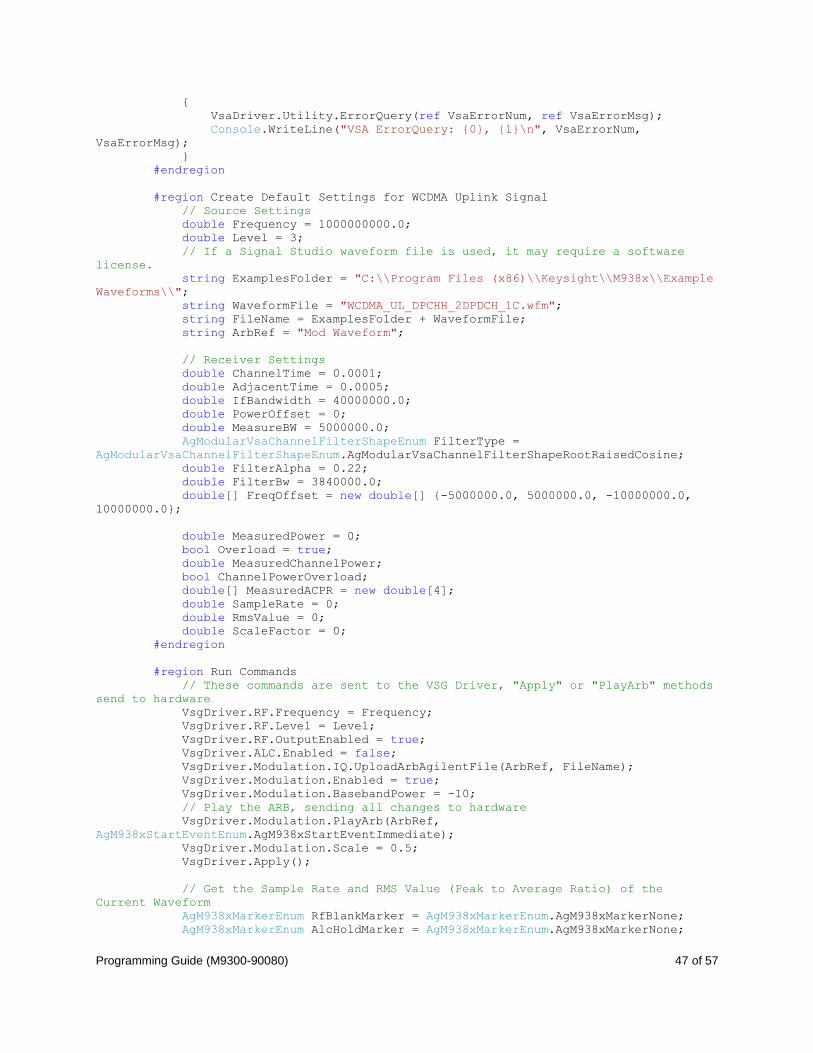
#region Create Default Settings for WCDMA Uplink Signal
// Source Settings
double Frequency = 1000000000.0;
double Level = 3;
// If a Signal Studio waveform file is used, it may require a software
license.
string ExamplesFolder = "C:\\Program Files (x86)\\Keysight\\M938x\\Example
Waveforms\\";
string WaveformFile = "WCDMA_UL_DPCHH_2DPDCH_1C.wfm";
string FileName = ExamplesFolder + WaveformFile;
string ArbRef = "Mod Waveform";
// Receiver Settings
double ChannelTime = 0.0001;
double AdjacentTime = 0.0005;
double IfBandwidth = 40000000.0;
double PowerOffset = 0;
double MeasureBW = 5000000.0;
AgModularVsaChannelFilterShapeEnum FilterType =
AgModularVsaChannelFilterShapeEnum.AgModularVsaChannelFilterShapeRootRaisedCosine;
double FilterAlpha = 0.22;
double FilterBw = 3840000.0;
double[] FreqOffset = new double[] {-5000000.0, 5000000.0, -10000000.0,
10000000.0};
double MeasuredPower = 0;
bool Overload = true;
double MeasuredChannelPower;
bool ChannelPowerOverload;
double[] MeasuredACPR = new double[4];
double SampleRate = 0;
double RmsValue = 0;
double ScaleFactor = 0;
#endregion
#region Run Commands
// These commands are sent to the VSG Driver, "Apply" or "PlayArb" methods
send to hardware
VsgDriver.RF.Frequency = Frequency;
VsgDriver.RF.Level = Level;
VsgDriver.RF.OutputEnabled = true;
VsgDriver.ALC.Enabled = false;
VsgDriver.Modulation.IQ.UploadArbAgilentFile(ArbRef, FileName);
VsgDriver.Modulation.Enabled = true;
VsgDriver.Modulation.BasebandPower = -10;
// Play the ARB, sending all changes to hardware
VsgDriver.Modulation.PlayArb(ArbRef,
AgM938xStartEventEnum.AgM938xStartEventImmediate);
VsgDriver.Modulation.Scale = 0.5;
VsgDriver.Apply();
// Get the Sample Rate and RMS Value (Peak to Average Ratio) of the
Current Waveform
AgM938xMarkerEnum RfBlankMarker = AgM938xMarkerEnum.AgM938xMarkerNone;
AgM938xMarkerEnum AlcHoldMarker = AgM938xMarkerEnum.AgM938xMarkerNone;
Programming Guide (M9300-90080) 48 of 57
VsgDriver.Modulation.IQ.ArbInformation(ArbRef, ref SampleRate, ref
RmsValue, ref ScaleFactor, ref RfBlankMarker, ref AlcHoldMarker);
// Setup the RF Path in the Receiver
VsaDriver.RF.Frequency = Frequency;
VsaDriver.RF.Power = Level + PowerOffset;
VsaDriver.RF.Conversion =
AgModularVsaConversionEnum.AgModularVsaConversionAuto;
VsaDriver.RF.PeakToAverage = RmsValue;
VsaDriver.RF.IFBandwidth = IfBandwidth;
// Configure the Acquisition
VsaDriver.AcquisitionMode =
AgModularVsaAcquisitionModeEnum.AgModularVsaAcquisitionModePower;
VsaDriver.PowerAcquisition.Bandwidth = MeasureBW;
VsaDriver.PowerAcquisition.Duration = ChannelTime;
VsaDriver.PowerAcquisition.ChannelFilter.Configure(FilterType,
FilterAlpha, FilterBw);
// Send Changes to hardware
VsaDriver.Apply();
VsaDriver.WaitUntilSettled(100);
string response = "y";
while (string.Compare(response, "y") == 0) {
Console.WriteLine("Press Enter to Run Test");
Console.ReadLine();
// Run a group of baseband power commands to change the source level
and make a power measurement at each step.
// Simulates Servo loop timing, but does not use the measured power to
adjust the next source level
VsaDriver.PowerAcquisition.Duration = ChannelTime;
VsaDriver.Apply();
double[] LevelOffset = new double[] {-3, -2, -1, -0.5, -0.75};
for (int Index = 0;Index < LevelOffset.Length - 1;Index++) {
VsgDriver.Modulation.BasebandPower = LevelOffset[Index];
VsgDriver.Apply();
VsaDriver.Arm();
VsaDriver.PowerAcquisition.ReadPower(0,
AgModularVsaPowerUnitsEnum.AgModularVsaPowerUnitsdBm, ref MeasuredPower, ref
Overload);
}
// Loop Through the channel offset frequencies for an ACPR measurement
// Use the last value of the servo loop for the channel power
MeasuredChannelPower = MeasuredPower;
ChannelPowerOverload = Overload;
VsaDriver.PowerAcquisition.Duration = AdjacentTime;
for (int Index = 0;Index < FreqOffset.Length;Index++) {
VsaDriver.PowerAcquisition.OffsetFrequency = FreqOffset[Index];
VsaDriver.Apply();
VsaDriver.Arm();
VsaDriver.PowerAcquisition.ReadPower(0,
AgModularVsaPowerUnitsEnum.AgModularVsaPowerUnitsdBm, ref MeasuredPower, ref
Overload);
MeasuredACPR[Index] = MeasuredPower - MeasuredChannelPower;
}
// Make sure the VSA frequency offset is back to 0 (on repeat)
VsaDriver.PowerAcquisition.OffsetFrequency = 0;
VsaDriver.Apply();
if (ChannelPowerOverload == true) {
Console.WriteLine("Channel Power Measurement Overload");
Programming Guide (M9300-90080) 49 of 57
}
Console.WriteLine("Channel Power: {0} dBm", MeasuredChannelPower);
Console.WriteLine("ACPR1 L: {0} dBc", MeasuredACPR[0]);
Console.WriteLine("ACPR1 U: {0} dBc", MeasuredACPR[1]);
Console.WriteLine("ACPR2 L: {0} dBc", MeasuredACPR[2]);
Console.WriteLine("ACPR2 U: {0} dBc", MeasuredACPR[3]);
Console.WriteLine("Repeat? y/n");
response = Console.ReadLine();
}
#endregion
}
catch (Exception ex)
{
Console.WriteLine("Exceptions for the drivers:\n");
Console.WriteLine(ex.Message);
}
finally
#region Close Driver Instances
{
if (VsgDriver != null && VsgDriver.Initialized)
{
// Close the driver
VsgDriver.Close();
Console.WriteLine("VSG Driver Closed");
}
if (VsaDriver != null && VsaDriver.Initialized)
{
// Close the driver
VsaDriver.Close();
Console.WriteLine("VSA Driver Closed\n");
}
}
#endregion
Console.WriteLine("Done - Press Enter to Exit");
Console.ReadLine();
}
}
}

Programming Guide (M9300-90080) 50 of 57
Disclaimer
© 2014 Keysight Technologies Inc. All rights reserved.
You have a royalty-free right to use, modify, reproduce and distribute this Sample Application (and/or any
modified version) in any way you find useful, provided that you agree that Keysight Technologies has no
warranty, obligations or liability for any Sample Application Files.
Keysight Technologies provides programming examples for illustration only. This sample program assumes
that you are familiar with the programming language being demonstrated and the tools used to create and
debug procedures. Keysight Technologies support engineers can help explain the functionality of Keysight
Technologies software components and associated commands, but they will not modify these samples to
provide added functionality or construct procedures to meet your specific needs.
Accessing Hardware-Specific Capabilities To access hardware-specific capabilities that are not in the common IAgModularVsa interface, you
must cast the reference to the instrument to the instrument-specific interface.
As an example, we have an M9391A PXIe VSA which is referred to by an IAgModularVsa interface.
To access the specific IF output filter that is in use, we must first cast to the instrument-specific
IAgM9391, then access the hardware-specific property.
IAgModularVsa VsaDriver = new AgM9391();
AgM9391IFOutputFilterEnum IFFilter =
((IAgM9391)VsaDriver).Modules.Downconverter.IFOutputFilter;

Programming Guide (M9300-90080) 51 of 57
Appendix 1:
Routing Triggers for Four M938xA VSG Configurations (Sharing One
Reference) The following is an example for routing triggers for four VSG configurations of modules.
// This is where we make sure the triggers that are required for the M9381A
// are routed properly across backplane segments on the chassis where necessary
//
// The M9018A has 3 trigger bus segments:
// Bus 1: slots 1-6
// Bus 2: slots 7-12
// Bus 3: slots 13-18
//
// For each M9381A in our system, there are three requirements:
// 1) PXI trigger from M9311A to M9310A for ALC. This defaults to trigger 7
// 2) PXI trigger from M9301A to M9311A for front panel External Trigger.
// This defaults to trigger 6.
// 3) None of these triggers can conflict with each other.
// For example, if there are two VSGs (or portions of a VSG)
// occupying a single chassis, they cannot both use the default trigger lines.
//
// To satisfy these requirements, we have two tools available to us:
// 1) Routing triggers between bus segments on the chassis
// 2) redefining the triggers used by the M9381A.
//
// For this example, we examine the routings needed for a 4 channel M9381A,
// with a single M9300A in slot 10.
// The other VSGs are in the following locations:
// VSG 1: slots 2-5
// VSG 2: slots 6-9
// VSG 3: slots 11-14
// VSG 4: slots 15-18
// We can make some observations about this configuration:
// 1) VSG1 and VSG2 have conflicting backplane trigger requirements, because the
M9311A modules will be in slots
// 2 and 6, therefore in the same bus segment
// 2) VSG 2 crosses segment boundary 1-2
// 3) VSG 2 and 3 have conflicting trigger requirements, because the M9301A module
from VSG 2 and M9311A module from VSG 3 will be in slots
// 9 and 11, therefore in the same bus segment
// 4) VSG 3 crosses segment boundary 2-3
// 5) VSG 3 and 4 have conflicting trigger requirements, because the M9301A module
from VSG 3 and M9311A module from VSG 4 will be in slots
// 14 and 15, therefore in the same bus segment
// 6) VSG 1 and VSG 4 are contained entirely within one trigger bus segment.
//
// To come up with a routing, we have to address all 5 of these issues above to
satisfy the 3 requirements outlined earlier.
//
// The simplest routing turns out to be the following
// 1) VSG 1 and VSG 3 use default triggers 6 and 7
// 2) VSG 2 and VSG 4 use triggers 5 and 8
// Route triggers on chassis backplane. Note that these will persist until a
power cycle, so this section could be performed in a separate
// program that runs at startup, for example as a service
M9018.TriggerBus.Connect(0,
Agilent.AgM9018.Interop.AgM9018TrigBusEnum.AgM9018TrigBus2To1);

Programming Guide (M9300-90080) 52 of 57
M9018.TriggerBus.Connect(5,
Agilent.AgM9018.Interop.AgM9018TrigBusEnum.AgM9018TrigBus1To2);
M9018.TriggerBus.Connect(6,
Agilent.AgM9018.Interop.AgM9018TrigBusEnum.AgM9018TrigBus3To2);
M9018.TriggerBus.Connect(7,
Agilent.AgM9018.Interop.AgM9018TrigBusEnum.AgM9018TrigBus2To3);
// Redefine triggers for VSG 2 and 4.
M9381chan2.System.PXIResources.AddHint("M9311A", "M9310A", "ALC TRIGGER",
Agilent.AgM938x.Interop.AgM938xPXIResourceTypeEnum.AgM938xPXIResourceTypeTTL_TRIGGER,
Agilent.AgM938x.Interop.AgM938xPXIResourcesEnum.AgM938xPXIResourcesTTL_TRIGGER_5);
M9381chan2.System.PXIResources.AddHint("M9301A", "M9311A", "EXTERNAL TRIGGER",
Agilent.AgM938x.Interop.AgM938xPXIResourceTypeEnum.AgM938xPXIResourceTypeTTL_TRIGGER,
Agilent.AgM938x.Interop.AgM938xPXIResourcesEnum.AgM938xPXIResourcesTTL_TRIGGER_0);
M9381chan4.System.PXIResources.AddHint("M9311A", "M9310A", "ALC TRIGGER",
Agilent.AgM938x.Interop.AgM938xPXIResourceTypeEnum.AgM938xPXIResourceTypeTTL_TRIGGER,
Agilent.AgM938x.Interop.AgM938xPXIResourcesEnum.AgM938xPXIResourcesTTL_TRIGGER_5);
M9381chan4.System.PXIResources.AddHint("M9301A", "M9311A", "EXTERNAL TRIGGER",
Agilent.AgM938x.Interop.AgM938xPXIResourceTypeEnum.AgM938xPXIResourceTypeTTL_TRIGGER,
Agilent.AgM938x.Interop.AgM938xPXIResourcesEnum.AgM938xPXIResourcesTTL_TRIGGER_0);
// Do other VSG things
Example programs may be found by selecting:
C:\Program Files (x86)\Keysight\M9391\Help\Examples
// Copy the following example code and compile it as a C# Console Application
using Agilent.AgM938x.Interop;
using Agilent.AgM9300.Interop;
using Agilent.AgM9018.Interop;
using System;
using System.Windows.Forms;
namespace VSG_SFP
{
public partial class TriggerRouting
{
public IAgM938xEx M9381chan1;
public IAgM938xEx M9381chan2;
public IAgM938xEx M9381chan3;
public IAgM938xEx M9381chan4;
public IAgM9018 M9018; // chassis
public string M9381Chan1resource = "M9381Chan1";
public string M9381Chan2resource = "M9381Chan2";
public string M9381Chan3resource = "M9381Chan3";
public string M9381Chan4resource = "M9381Chan4";
public string M9018resource = "PXI15::0::0::INSTR";
public void RouteTriggers()
{
int errorcode = -1; string message = string.Empty;
bool idquery = true;
bool reset = true;
bool simulateHardware = false;
string M9381options = string.Format(
"QueryInstrStatus=true, Simulate={0}, M9381Setup= Model=,
Trace=false", (simulateHardware ? "true" : "false"));
string M9018options = string.Format(
"QueryInstrStatus=true, Simulate={0}, M9018Setup= Model=,
Trace=false", (simulateHardware ? "true" : "false"));
Programming Guide (M9300-90080) 53 of 57
try
{
M9381chan1 = new AgM938x();
M9381chan2 = new AgM938x();
M9381chan3 = new AgM938x();
M9381chan4 = new AgM938x();
M9018 = new AgM9018();
// Initialize M9018A Chassis
M9018.Initialize(M9018resource, idquery, reset, M9018options);
//Initialize M9381 Channel 1
M9381chan1.Initialize(M9381Chan1resource, idquery, reset,
M9381options);
// Clear startup messages & warnings if any.
do
{
M9381chan1.Utility.ErrorQuery(ref errorcode, ref message);
if (errorcode != 0)
Console.WriteLine(message);
} while (errorcode != 0);
//Initialize M9381 Channel 2
M9381chan2.Initialize(M9381Chan2resource, idquery, reset,
M9381options);
// Clear startup messages & warnings if any.
do
{
M9381chan2.Utility.ErrorQuery(ref errorcode, ref message);
if (errorcode != 0)
Console.WriteLine(message);
} while (errorcode != 0);
//Initialize M9381 Channel 3
M9381chan3.Initialize(M9381Chan3resource, idquery, reset,
M9381options);
// Clear startup messages & warnings if any.
do
{
M9381chan3.Utility.ErrorQuery(ref errorcode, ref message);
if (errorcode != 0)
Console.WriteLine(message);
} while (errorcode != 0);
//Initialize M9381 Channel 4
M9381chan4.Initialize(M9381Chan4resource, idquery, reset,
M9381options);
// Clear startup messages & warnings if any.
do
{
M9381chan4.Utility.ErrorQuery(ref errorcode, ref message);
if (errorcode != 0)
Console.WriteLine(message);
} while (errorcode != 0);
// This is where we do the work to make sure the triggers that are
required for the M9381A
Programming Guide (M9300-90080) 54 of 57
// are routed properly across backplane segments on the chassis where
necessary
//
// The M9018A has 3 trigger bus segments:
// Bus 1: slots 1-6
// Bus 2: slots 7-12
// Bus 3: slots 13-18
//
// For each M9381A in our system, there are three requirements:
// 1) There must be a PXI trigger from M9311A to M9310A for ALC. This
defaults to trigger 7
// 2) There must be a PXI trigger from M9301A to M9311A for front
panel External Trigger. This defaults to trigger 6.
// 3) None of these triggers can conflict with each other. For
example, if there are two VSGs (or portions of a VSG)
// occupying a single chassis, they cannot both use the default
trigger lines.
//
// To satisfy these requirements, we have two tools available to us:
// 1) Routing triggers between bus segments on the chassis
// 2) redefining the triggers used by the M9381A.
//
// For this example, we examine the routings needed for a 4 channel
M9381A, with a single M9300A in slot 10.
// The other VSGs are in the following locations:
// VSG 1: slots 2-5
// VSG 2: slots 6-9
// VSG 3: slots 11-14
// VSG 4: slots 15-18
// We can make some observations about this configuration:
// 1) VSG1 and VSG2 have conflicting backplane trigger requirements,
because the M9311A modules will be in slots
// 2 and 6, therefore in the same bus segment
// 2) VSG 2 crosses segment boundary 1-2
// 3) VSG 2 and 3 have conflicting trigger requirements, because the
M9301A module from VSG 2 and M9311A module from VSG 3 will be in slots
// 9 and 11, therefore in the same bus segment
// 4) VSG 3 crosses segment boundary 2-3
// 5) VSG 3 and 4 have conflicting trigger requirements, because the
M9301A module from VSG 3 and M9311A module from VSG 4 will be in slots
// 14 and 15, therefore in the same bus segment
// 6) VSG 1 and VSG 4 are contained entirely within one trigger bus
segment.
//
// To come up with a routing, we have to address all 5 of these issues
above to satisfy the 3 requirements outlined earlier.
//
// The simplest routing turns out to be the following
// 1) VSG 1 and VSG 3 use default triggers 6 and 7
// 2) VSG 2 and VSG 4 use triggers 5 and 8
// Route triggers on chassis backplane. Note that these will persist
until a power cycle, so this section could be performed in a separate
// program that runs at startup, for example as a service
M9018.TriggerBus.Connect(0,
Agilent.AgM9018.Interop.AgM9018TrigBusEnum.AgM9018TrigBus2To1);
M9018.TriggerBus.Connect(5,
Agilent.AgM9018.Interop.AgM9018TrigBusEnum.AgM9018TrigBus1To2);
M9018.TriggerBus.Connect(6,
Agilent.AgM9018.Interop.AgM9018TrigBusEnum.AgM9018TrigBus3To2);
M9018.TriggerBus.Connect(7,
Agilent.AgM9018.Interop.AgM9018TrigBusEnum.AgM9018TrigBus2To3);

Programming Guide (M9300-90080) 55 of 57
// Redefine triggers for VSG 2 and 4.
M9381chan2.System.PXIResources.AddHint("M9311A", "M9310A", "ALC
TRIGGER",
Agilent.AgM938x.Interop.AgM938xPXIResourceTypeEnum.AgM938xPXIResourceTypeTTL_TRIGGER,
Agilent.AgM938x.Interop.AgM938xPXIResourcesEnum.AgM938xPXIResourcesTTL_TRIGGER_5);
M9381chan2.System.PXIResources.AddHint("M9301A", "M9311A", "EXTERNAL
TRIGGER",
Agilent.AgM938x.Interop.AgM938xPXIResourceTypeEnum.AgM938xPXIResourceTypeTTL_TRIGGER,
Agilent.AgM938x.Interop.AgM938xPXIResourcesEnum.AgM938xPXIResourcesTTL_TRIGGER_0);
M9381chan4.System.PXIResources.AddHint("M9311A", "M9310A", "ALC
TRIGGER",
Agilent.AgM938x.Interop.AgM938xPXIResourceTypeEnum.AgM938xPXIResourceTypeTTL_TRIGGER,
Agilent.AgM938x.Interop.AgM938xPXIResourcesEnum.AgM938xPXIResourcesTTL_TRIGGER_5);
M9381chan4.System.PXIResources.AddHint("M9301A", "M9311A", "EXTERNAL
TRIGGER",
Agilent.AgM938x.Interop.AgM938xPXIResourceTypeEnum.AgM938xPXIResourceTypeTTL_TRIGGER,
Agilent.AgM938x.Interop.AgM938xPXIResourcesEnum.AgM938xPXIResourcesTTL_TRIGGER_0);
// Do other VSG things
}
catch (Exception ex)
{
MessageBox.Show(ex.Message);
}
}
}
}
Disclaimer
© 2014 Keysight Technologies Inc. All rights reserved.
You have a royalty-free right to use, modify, reproduce and distribute this Sample Application (and/or any
modified version) in any way you find useful, provided that you agree that Keysight Technologies has no
warranty, obligations or liability for any Sample Application Files.
Keysight Technologies provides programming examples for illustration only. This sample program assumes
that you are familiar with the programming language being demonstrated and the tools used to create and
debug procedures. Keysight Technologies support engineers can help explain the functionality of Keysight
Technologies software components and associated commands, but they will not modify these samples to
provide added functionality or construct procedures to meet your specific needs.
Programming Guide (M9300-90080) 56 of 57
Glossary ADE (application development environment) — An integrated suite of software development
programs. ADEs may include a text editor, compiler, and debugger, as well as other tools used
in creating, maintaining, and debugging application programs. Example: Microsoft Visual
Studio.
API (application programming interface) — An API is a well-defined set of set of software
routines through which application program can access the functions and services provided by
an underlying operating system or library. Example: IVI Drivers
C# (pronounced “C sharp”) — C-like, component-oriented language that eliminates much of
the difficulty associated with C/C++.
Direct I/O — commands sent directly to an instrument, without the benefit of, or interference
from a driver. SCPI Example: SENSe:VOLTage:RANGe:AUTO Driver (or device driver) — a
collection of functions resident on a computer and used to control a peripheral device.
DLL (dynamic link library) — An executable program or data file bound to an application
program and loaded only when needed, thereby reducing memory requirements. The functions
or data in a DLL can be simultaneously shared by several applications.
Input/Output (I/O) layer — The software that collects data from and issues commands to
peripheral devices. The VISA function library is an example of an I/O layer that allows
application programs and drivers to access peripheral instrumentation.
IVI (Interchangeable Virtual Instruments) — a standard instrument driver model defined by the
IVI Foundation that enables engineers to exchange instruments made by different
manufacturers without rewriting their code. www.ivifoundation.org
IVI COM drivers (also known as IVI Component drivers) — IVI COM presents the IVI driver as a
COM object in Visual Basic. You get all the intelligence and all the benefits of the development
environment because IVI COM does things in a smart way and presents an easier, more
consistent way to send commands to an instrument. It is similar across multiple instruments.
Microsoft COM (Component Object Model) — The concept of software components is
analogous to that of hardware components: as long as components present the same interface
and perform the same functions, they are interchangeable. Software components are the
natural extension of DLLs. Microsoft developed the COM standard to allow software
manufacturers to create new software components that can be used with an existing
application program, without requiring that the application be rebuilt. It is this capability that
allows T&M instruments and their COM-based IVI-Component drivers to be interchanged.
.NET Framework — The .NET Framework is an object-oriented API that simplifies application
development in a Windows environment. The .NET Framework has two main components: the
common language runtime and the .NET Framework class library.
VISA (Virtual Instrument Software Architecture) — The VISA standard was created by the
VXIplug&play Foundation. Drivers that conform to the VXIplug&play standards always perform
I/O through the VISA library. Therefore if you are using Plug and Play drivers, you will need the
Programming Guide (M9300-90080) 57 of 57
VISA I/O library. The VISA standard was intended to provide a common set of function calls
that are similar across physical interfaces. In practice, VISA libraries tend to be specific to the
vendor’s interface.
VISA-COM — The VISA-COM library is a COM interface for I/O that was developed as a
companion to the VISA specification. VISA-COM I/O provides the services of VISA in a COM-
based API. VISA-COM includes some higher-level services that are not available in VISA, but in
terms of low-level I/O communication capabilities, VISA-COM is a subset of VISA. Keysight
VISA-COM is used by its IVI-Component drivers and requires that Keysight VISA also be
installed.
References 1. Understanding Drivers and Direct I/O, Application Note 1465-3 (Keysight Part Number: 5989-
0110EN)
2. Digital Baseband Tuning Technique Speeds Up Testing, by Bill Anklam, Victor Grothen and Doug
Olney, Keysight Technologies, Santa Clara, CA, April 15, 2013, Microwave Journal
3. www.ivifoundation.org