Keysight i3070 Series 5 In-Circuit Test System
71
Keysight i3070 Series 5 In-Circuit Test System Site Preparation
Transcript of Keysight i3070 Series 5 In-Circuit Test System

Keysight i3070 Series 5In-Circuit Test System
Site Preparation

Notices© Keysight Technologies 2012-2014
No part of this manual may be reproduced in any form or by any means (including electronic storage and retrieval or translation into a foreign language) without prior agreement and written consent from Keysight Technologies, Inc. as governed by United States and international copyright laws.
Warranty
THE MATERIAL CONTAINED IN THIS DOCUMENT IS PROVIDED "AS IS," AND IS SUBJECT TO BEING CHANGED, WITHOUT NOTICE, IN FUTURE EDITIONS. FURTHER, TO THE MAXIMUM EXTENT PERMITTED BY APPLICABLE LAW, KEYSIGHT DISCLAIMS ALL WARRANTIES, EITHER EXPRESS OR IMPLIED WITH REGARD TO THIS MANUAL AND ANY INFORMATION CONTAINED HEREIN, INCLUDING BUT NOT LIMITED TO THE IMPLIED WARRANTIES OF MERCHANTABILITY AND FITNESS FOR A PARTICULAR PURPOSE. KEYSIGHT SHALL NOT BE LIABLE FOR ERRORS OR FOR INCIDENTAL OR CONSEQUENTIAL DAMAGES IN CONNECTION WITH THE FURNISHING, USE, OR PERFORMANCE OF THIS DOCUMENT OR ANY INFORMATION CONTAINED HEREIN. SHOULD KEYSIGHT AND THE USER HAVE A SEPARATE WRITTEN AGREEMENT WITH WARRANTY TERMS COVERING THE MATERIAL IN THIS DOCUMENT THAT CONFLICT WITH THESE TERMS, THE WARRANTY TERMS IN THE SEPARATE AGREEMENT WILL CONTROL.
Technology Licenses
The hardware and/or software described in this document are furnished under a license and may be used or copied only in accordance with the terms of such license.
Restricted Rights Notice
If software is for use in the performance of a U.S. Government prime contract or subcontract, Software is delivered and licensed as "Commercial computer software" as defined in DFAR 252.227-7014 (June 1995), or as a "commercial item" as defined in FAR 2.101(a) or as "Restricted computer software" as defined in FAR 52.227-19 (June 1987) or any equivalent agency regulation or contract clause. Use, duplication or disclosure of Software is subject to Keysight Technologies’ standard commercial license terms, and non-DOD Departments and Agencies of the U.S. Government will receive no greater than Restricted Rights as defined in FAR 52.227-19(c)(1-2) (June 1987). U.S. Government users will receive no greater than Limited Rights as defined in FAR 52.227-14 (June 1987) or DFAR 252.227-7015 (b)(2) (November 1995), as applicable in any technical data.
Safety Notices
A CAUTION notice denotes a hazard. It calls attention to an operating procedure, practice, or the like that, if not correctly performed or adhered to, could result in damage to the product or loss of important data. Do not proceed beyond a CAUTION notice until the indicated conditions are fully understood and met.
A WARNING notice denotes a hazard. It calls attention to an operating procedure, practice, or the like that, if not correctly performed or adhered to, could result in personal injury or death. Do not proceed beyond a WARNING notice until the indicated conditions are fully understood and met.

Contents
1 Site Preparation Process
The Importance of Site Preparation 1-2Responsibilities 1-3
Keysight’s Responsibilities 1-3Customer’s Responsibilities 1-4
The Site Preparation Process 1-5Site Prep Checklist 1-6
2 Planning
The System Plan Drawing 2-2Assigning Specialists 2-5
3 Structural Requirements
Floor Requirements 3-2Anti-Static Surface 3-2
Moving Access Requirements 3-3Dimensions of the Crated System 3-3Dimensions of the Uncrated System 3-3Access Requirements 3-4
Storage Space Requirements 3-5
4 RF Attenuation Requirements
Introduction 4-2Calculating Site Attenuation 4-3
5 Environmental Requirements
Air Quality Requirements 5-2Air Temperature Requirements 5-3
Air Temperature Specifications 5-3Cooling Requirements 5-3
Humidity Requirements 5-4
6 Power Requirements
Customer Responsibilities 6-2About the PDU 6-3Power Requirements 6-4
Mains Disconnect 6-4Power Drop 6-5Basic Power Quality Survey 6-7Connecting Power to the PDU 6-7
Is PDU Re-wiring Necessary? 6-9PDU Wiring Diagrams 6-10
One-Module System AC Outlets 6-11Two-Module System AC Outlets 6-14Four-Module System AC Outlets 6-17
iii

7 Compressed Air and Vacuum Requirements
Introduction 7-2Compressed Air Requirements 7-3
Connecting Air to the Testhead 7-3Compressed Air Specifications 7-4Air Quality 7-4
Vacuum Requirements 7-5Vacuum Recommendations and Guidelines 7-5Connecting Vacuum to the Testhead 7-6
Compressed Air and Vacuum Primer 7-7
8 Receiving and Moving Instructions
Inventory the Shipment 8-2Uncrating the System and Support Bay 8-3Placing the System 8-4Re-shipping a System 8-5
iv

Keysight i3070 Series 5In-Circuit Test System
Site Preparation
1 Site Preparation Process
The Importance of Site Preparation 1-2
Responsibilities 1-3
The Site Preparation Process 1-5
Site Prep Checklist 1-6
1 Site Preparation Process
The Importance of Site Preparation
The Keysight i3070 family of in-circuit test (ICT) systems includes complex and sophisticated automatic test equipment. To ensure that your site is properly equipped for your new system, and to minimize the possibility of problems or delays in system installation, you must consider many things during site preparation. Before calling your local Keysight representative to install your i3070 system, read and follow the recommendations provided in this manual.
This manual contains the following chapters:
• Chapter 1, Site Preparation Process (this chapter) discusses your responsibilities, lists Keysight’s responsibilities, and provides a checklist to use as you proceed.
• Chapter 2, Planning discusses choosing a site for your system, designing your site layout, assigning people to do various preparation tasks, and scheduling your preparations.
• Chapter 3, Structural Requirements describes floor, access, and storage requirements.
• Chapter 4, RF Attenuation Requirements describes the additional RF attenuation required as part of the installation to meet the installed radiated emission limits for some countries.
• Chapter 5, Environmental Requirements describes air quality, temperature, humidity, and electromagnetic shielding requirements.
• Chapter 6, Power Requirements describes power requirements for the various parts of the system and mains power connections.
• Chapter 7, Compressed Air and Vacuum Requirements describes the compressed air and vacuum that the system requires.
• Chapter 8, Receiving and Moving Instructions describes the uncrating, handling, and re-shipping process for the i3070.
1-2 Site Preparation

Site Preparation Process 1
Responsibilities
Successful system preparation and installation requires planning and effort by both you and Keysight. Following are summaries of each party’s responsibilities.
• Keysight’s Responsibilities
• Customer’s Responsibilities
Keysight’s Responsibilities
As a part of the purchase of a Keysight board test system, Keysight will provide the following:
• Site Preparation Suggestion — To help you begin, a Keysight authorized representative will visit you to help you understand what you will need to do to make your site ready for your system and answer any questions you may have. This is called the “Initial Site Preparation Visit” and the Keysight representative will bill up to 2 hours to Keysight Technologies.
• Electrical and Environmental Inspection — After primary power has been installed at the site, a Keysight representative will inspect the lines to verify that your electrical power is suitable for the system. At the same time, the Keysight representative will inspect the site to verify that its environmental characteristics conform to the site preparation specifications. The representative will also answer any questions you may have. This is called the “Verifying Site Preparation Visit” and the Keysight representative will bill up to 2 hours to Keysight.
• Installation — After all components of the system have been moved to the site, compressed air and vacuum have been installed, and primary power has been run to the system location, a Keysight representative will complete the system installation. The Keysight representative will plug in the pre-installed power cord after testing the power.
Installation includes removing the system from the pallet, unpacking the smaller boxes, connecting cabling, starting the system, customizing the system software, and performing a complete system verification. The representative will also answer any questions you may have. This is called the “Installation Visit” and the Keysight representative will bill up to 4 hours to Keysight.
• Warranty — The Keysight board test systems include a one-year warranty that provides on-site hardware repair, software support and software updates.
• Insurance — The system is insured by Keysight until it is delivered to your loading dock.
Site Preparation 1-3

1 Site Preparation Process
Customer’s Responsibilities
While you are primarily responsible for these activities, you can ask the Keysight representative for advice and information about services offered.
• Insurance — You must provide insurance coverage for your system from the time it is delivered to your facility.
• Software Support Contract — You are responsible for initiating and renewing support contracts for software, documentation updates, and telephone support. Software support and updates are included during the warranty period.
• Site Preparation and Maintenance — You must supply all labor and materials used in site construction and maintenance. You are also responsible for obtaining any building permits and licenses required by local laws and regulations.
• Proper Use of the System — You are responsible for ensuring that use of the system is consistent with local laws and regulations.
• Uncrating — You should remove the tri-wall box from the testhead, but not remove the system from the pallet. The Keysight representative will remove the testhead from the pallet. You may inventory the shipment using the enclosed packing list. You may leave the smaller boxes for the Keysight representative to unpack when the system is installed.
• Inspection — You must inspect the system for physical damage. If you believe that your system was damaged in shipment, call your Keysight representative.
• Moving — Moving the equipment from the receiving dock to the installation site is the customers responsibility. The system should be moved, after the tri-wall box is removed, to an area safe from damage or misplaced boxes.
• Wiring and Cabling — Wiring primary power to the system is your responsibility, as is installing communications cabling to the system. The actual power connection to the system will be made after the Keysight representative has removed the system from the pallet and moved it to the desired location.
It will be difficult to remove the tri-wall box in a room with less than 2.5 meter (8 foot) clearance.
1-4 Site Preparation

Site Preparation Process 1
The Site Preparation Process
This section describes the steps of the Keysight system site preparation process.
1 The Site Prep Visit
A Keysight representative will come to your site to discuss what you will need to do to make your site ready for your system. During this visit, the Keysight representative will review this manual and answer any questions you may have. This will help you get started preparing your site.
2 Site Planning
The site planning step is crucial. A little effort invested in understanding and planning your system will save much effort at installation time. Plan your system area using Chapter 2, Planning. Assign specialists to perform the various tasks. Make a “system plan drawing” that you and the Keysight representative can use to install your system. If you need help, call your Keysight representative. Schedule all site preparation activities.
3 Site Plan Implementation
Implement the plan. Use Chapter 3, Structural Requirements through Chapter 8, Receiving and Moving Instructions and the system plan drawing. Work with your specialists.
4 Site Verification Visit
The site verification visit allows the Keysight representative to review your preparations and answer any remaining questions. The Keysight representative will check your power to verify that it is suitable for the system. The Keysight representative will also check your compressed air and vacuum hookups.
5 Receiving the System
When the system arrives at your site, remove the tri-wall box from the testhead, but do not remove the system from the pallet. The Keysight representative will remove the testhead from the pallet. You may inventory the shipment using the enclosed packing list. You may leave the smaller boxes for the Keysight representative to unpack when the system is installed. You should move the system to the site where it will be installed, or a safe storage area.
Site Preparation 1-5

1 Site Preparation Process
Site Prep Checklist
Use this checklist to check off each task as you complete it.
Table 1-1 Site preparation checklist
Task Checklist
Planning [ ] Location chosen?
Specialists assigned?
Site Coordinator: __________________________________________________________
System Administrator: __________________________________________________________
Structural Specialist: __________________________________________________________
EMC Specialist: __________________________________________________________
Environmental Specialist: __________________________________________________________
Electrical Specialist: __________________________________________________________
Vacuum Specialist: __________________________________________________________
Compressed Air Specialist: __________________________________________________________
Communications Specialist: __________________________________________________________
[ ] Schedule Created:
Structural Requirements [ ] Floor suitable?
[ ] Room to move the big box? If not, do you have a place to unpack it?
[ ] Storage sufficient?
RF Attenuation Requirements [ ] Required to meet EMC directives?
[ ] Additional attenuation sufficient?
Environmental Requirements [ ] Air quality suitable?
[ ] Ambient temperature suitable?
[ ] Cooling sufficient?
[ ] Humidity suitable?
[ ] Electromagnetic environment suitable?
1-6 Site Preparation

Site Preparation Process 1
Power Requirements System Power
What power option is your system? Opt. _______________
[ ] AC mains power verified?
[ ] Mains disconnect installed?
[ ] Do you need to install power conditioning equipment?
[ ] Do you need to install a new transformer?
[ ] What system drop wire size is required? Wire Size ____________
[ ] What system drop breaker size is required? Breaker Size ____________
[ ] Power cable installed for mains?
Connect Mains Power
[ ] Power installed to system?
Convenience Outlet Power
[ ] Testhead strip printer?
[ ] Testhead server?
Compressed Air and Vacuum Requirements
[ ] Compressed air line installed?
[ ] Vacuum plan done?
[ ] How many solenoids needed? _____________
[ ] Vacuum equipment installed?
Networking [ ] LAN cabling installed?
The i3070 communicates with other systems via IEEE 802.3 Local Area Networking. All the necessary software and licensing comes with the system, but the customer is responsible for installing the external LAN cabling to the i3070.
The internal testhead LAN within each i3070 system — which includes the System Card and Module Control Card in each module — is identical between systems. However, the hardware address for each System Card and Module Control Card is unique. The hardware address is assigned at the factory and is marked on each card.
The remaining items go beyond site preparation, but must be completed before installation
Receiving and Moving Instructions [ ] Insurance coverage arranged for arrival?
[ ] System inspected for physical damage?
[ ] Shipment inventoried?
[ ] Equipment moved to installation site?
[ ] Testhead unpacked (tri-wall box removed, but not removed from the pallet). The Keysight representative will unpack the smaller boxes and move the system as part of installation.
Table 1-1 Site preparation checklist (continued)
Task Checklist
Site Preparation 1-7

1 Site Preparation Process
1-8 Site Preparation
Keysight i3070 Series 5In-Circuit Test System
Site Preparation
2 Planning
The System Plan Drawing 2-2
Assigning Specialists 2-5
2 Planning
The System Plan Drawing
Many things need to be done before the system can be installed. If you make a system plan drawing, you can use it to plan all aspects of site preparation. A complete drawing should detail power availability, communications cabling, compressed air and vacuum lines, and system placement with respect to other equipment. It can also serve to verify physical access.
Planning Aids
Use Figure 2-1 and Figure 2-2 to lay out your system on the system plan drawing.
Before installing the system you should determine whether the operator will stand or sit and whether the operator will work from the right or left side of the testhead. These decisions will determine whether the monitor and keyboard should be on the right or left. If you want the monitor and keyboard to be in front of the testhead as shown, you should install them on the same side of the testhead as the operator. However, if you want the monitor and keyboard to be above the testhead, you should install them on the opposite side from the operator. It is important to make this decision correctly.
The figures show the systems with support bays. If your system does not have a support bay, modify your layout accordingly. See Chapter 3, Structural Requirements for the exact dimensions of individual testheads and support bays.
Always allow 1 meter (3 feet) of space behind the system so service personnel can access the hardware inside the testhead and support bay and operators can access the red PDU mains disconnect switch.
On your system plan, determine the location of the facility mains disconnect. It should be installed within 3 meters of the system, where it can be easily reached by the system operator without requiring the system to be moved to access the disconnect. See Mains Disconnect on page 6-4 for more information.
2-2 Site Preparation

Planning 2
Figure 2-1 Recommended layouts for Medalist i3070 systems
(a) i327x 1-module system
(c) i327x 2-module system
(b) i327x plus2-module small footprint system with support bay
Site Preparation 2-3

2 Planning
Figure 2-2 Recommended layouts for i3070 systems (continued)
(d) i307x 4-module system with support bay (right to left layout)
(e) i307x 4-module system with support bay (left to right layout)
(f) i307x system with board handler
2-4 Site Preparation
Planning 2
Assigning Specialists
The concept of “specialists” represents the recognition that, at most facilities, no one person will do all the preparatory work.
• Site Coordinator
One person should manage the site preparation process. In this manual, that person will be called the site coordinator. The site coordinator will plan the installation, maintain the system plan drawing, and check off the site prep checklist. The site coordinator may assign all the other specialists.
• System Administrator
Any successful system requires good system administration. One person should have responsibility of the system administration.
• Structural Specialist
The structural specialist will verify that the floor is suitable for the system in terms of strength and anti-static properties. This specialist will examine the route from the receiving area to the system’s proposed location and decide how best to move the system to that place. Storage will be required after the system is in operation, and the structural specialist will decide what storage is needed. Chapter 3, Structural Requirements is the primary reference for the structural specialist.
• EMC Specialist
If the installation is in a location where radiated radio-frequency (RF) emissions are restricted for this equipment, such as member states of the European Union, Canada, USA or Australia, an EMC Specialist is needed to assure that the installation meets the required attenuation. This specialist will also be responsible to arrange any on-site testing that may be needed. Chapter 4, RF Attenuation Requirements is the primary reference for the EMC Specialist.
• Environmental Specialist
The environmental specialist will verify that your site’s environment is suitable for the system. Air quality, ambient temperature, cooling capacity, humidity, and electromagnetic interference are areas that the environmental specialist must address. Chapter 5, Environmental Requirements contains information for this specialist.
• Electrical Specialist
The electrical specialist will plan and install the mains power for the system, support bay and the convenience outlets for the other system equipment. These items should be marked on the system plan drawing. Chapter 6, Power Requirements contains the electrical information.
• Air and Vacuum Specialist
The compressed air and vacuum specialist will plan and install the compressed air supply for your system. Air lines should be marked on the system plan drawing. The specialist will also plan and install your system’s vacuum control system. Vacuum lines should be marked on the system plan drawing. The information pertaining to air and vacuum control is in Chapter 7, Compressed Air and Vacuum Requirements.
• Communications Specialist
The communications specialist will install the LAN cables to your system. LAN cables and telephone lines should be marked on the system plan drawing.
Site Preparation 2-5

2 Planning
2-6 Site Preparation
Keysight i3070 Series 5In-Circuit Test System
Site Preparation
3 Structural Requirements
Floor Requirements 3-2
Moving Access Requirements 3-3
Storage Space Requirements 3-5

3 Structural Requirements
Floor Requirements
The system tester (testhead and support bay, if included) is the heaviest part of the system. The controller and test development stations present no special load-bearing concern. The following table lists the approximate weights of fully-loaded systems.
Anti-Static Surface
Static electricity is destructive to your production process and to your board test system. Careless handling and poor planning can cost you yield and system reliability.
This is not an exhaustive description of anti-static precautions but a reminder as you plan your system area:
• Anti-static flooring. Plan to use an anti-static floor covering or mats.
• Grounding straps. Plan for foot straps in conjunction with anti-static flooring and wrist straps for system operators. The testhead has external connectors for wrist straps.
• Anti-static DUT storage. Plan for anti-static tote bins for your devices-under-test and storage for anti-static bags.
Table 3-2 System weights
System Type Product Weight
i307x4-module system
Testhead 429 kg (945 lb)
Testhead on pallet 525 kg (1160 lb)
Maximum Point Floor Loading (each leg) 275 kg (600 lb)
Support Bay Support Bay 209 kg (460 lb)
Support Bay on pallet 277 kg (610 lb)
Maximum Point Floor Loading (each leg) 185 kg (400 lb)
i317x2-module system
Testhead 429 kg (945 lb)
Testhead on pallet 525 kg (1160 lb)
Maximum floor point loading each leg 275 kg (600 lb)
i327x plus2-module small footprint system
Testhead 394 kg (868 lb)
Testhead on pallet 593 kg (1307 lb)
i327x1-Module System
Testhead 340 kg (750 lb)
Testhead on pallet 477 kg (1050 lb)
Mux system: 34595A or 44904A off pallet
Instrument rack 182 kg (400 lb)
3-2 Site Preparation
Structural Requirements 3
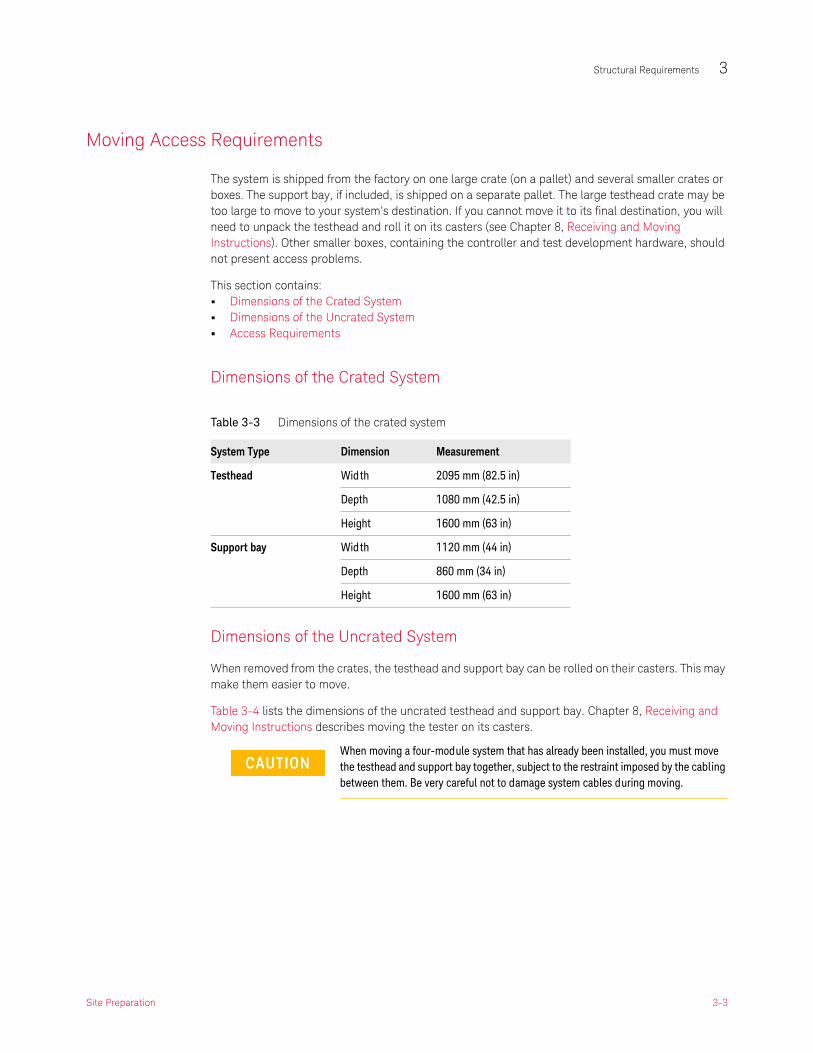
Moving Access Requirements
The system is shipped from the factory on one large crate (on a pallet) and several smaller crates or boxes. The support bay, if included, is shipped on a separate pallet. The large testhead crate may be too large to move to your system’s destination. If you cannot move it to its final destination, you will need to unpack the testhead and roll it on its casters (see Chapter 8, Receiving and Moving Instructions). Other smaller boxes, containing the controller and test development hardware, should not present access problems.
This section contains:• Dimensions of the Crated System• Dimensions of the Uncrated System• Access Requirements
Dimensions of the Crated System
Dimensions of the Uncrated System
When removed from the crates, the testhead and support bay can be rolled on their casters. This may make them easier to move.
Table 3-4 lists the dimensions of the uncrated testhead and support bay. Chapter 8, Receiving and Moving Instructions describes moving the tester on its casters.
Table 3-3 Dimensions of the crated system
System Type Dimension Measurement
Testhead Width 2095 mm (82.5 in)
Depth 1080 mm (42.5 in)
Height 1600 mm (63 in)
Support bay Width 1120 mm (44 in)
Depth 860 mm (34 in)
Height 1600 mm (63 in)
When moving a four-module system that has already been installed, you must move the testhead and support bay together, subject to the restraint imposed by the cabling between them. Be very careful not to damage system cables during moving.
Site Preparation 3-3

3 Structural Requirements
Access Requirements
• Ramps
When moved on its casters, the testhead will negotiate ramps with inclines up to 8% before the leveling feet drag on the floor.
• Hallways and door
As a rough guide, if you have room to move a 4-foot by 8-foot (1.25 m x 2.5 m) sheet of plywood, parallel to the floor, through hallways and doors, you will be able to move the crated testhead. If you cannot move the testhead crate all the way, remove it from its crate in a receiving area and push it on its casters to the destination.
Table 3-4 Dimensions of the uncrated system
System Type Dimension Measurement
i307x4-module system testhead
Width 1765 mm (69.5 in)
Depth 795 mm (31 in)
Height 907 mm (35.5 in)
Support bay Width 600 mm (23.5 in)
Depth 940 mm (37 in)
Height 1320 mm (52 in)
i317x2-module system testhead
Width 1765 mm (69.5 in)
Depth 795 mm (31 in)
Height 907 mm (35.5 in)
i327x plus2-module small footprint system
Width 1529 mm (60 in)
Depth 795 mm (31 in)
Height 907 mm (35.5 in)
i327x1-Module System Testhead
Width 1238 mm (48.5 in)
Depth 795 mm (31 in)
Height 907 mm (35.5 in)
3-4 Site Preparation

Structural Requirements 3
Storage Space Requirements
Setting up your system requires planning for storage. Obviously, you will need a handling and staging area for the boards you will be testing. Not so obviously, there are other things that you will need to store, such as the test fixtures.
Backup media storage
The i3070 system is reliable, but no system is safe against data loss due to system disk or computer failure. Run system backups at regular intervals. Before the system is installed, plan for backup media storage in the system area. To be safer still, always place a recent backup in a different area or building.
Fixture storage
You will have a significant investment in your system fixtures. They are precision machines and must be kept clean and undamaged. Plan safe and dust-free storage near the testhead for your fixtures.
You will receive a Pin Verification Fixture with the first testhead at your site to use to test the MINT pins of your systems. Be sure to keep the Pin Verification Fixture in your fixture storage area.
Note the following with respect to fixture storage:
• Don’t store fixtures on painted shelves. The bottom of the fixture will scrape small particles of paint off the shelf which will fall into and contaminate the testhead’s interface pins.
• If possible, cover your fixtures when not in use, especially when the air contains a high level of particulates.
• Don’t store fixtures on paper-, cardboard-, or carpet-covered surfaces. These materials could contain corrosive substances that would react with the fixture’s gold-plated personality pins.
• Don’t store fixtures on wooden shelves. Wood splinters can be carried on the bottom of the fixture to the testhead, thereby contaminating testhead interface pins.
• Don’t stack fixtures on top of one another.
Site Preparation 3-5

3 Structural Requirements
3-6 Site Preparation

Keysight i3070 Series 5In-Circuit Test System
Site Preparation
4 RF Attenuation Requirements
Introduction 4-2
Calculating Site Attenuation 4-3
4 RF Attenuation Requirements
Introduction
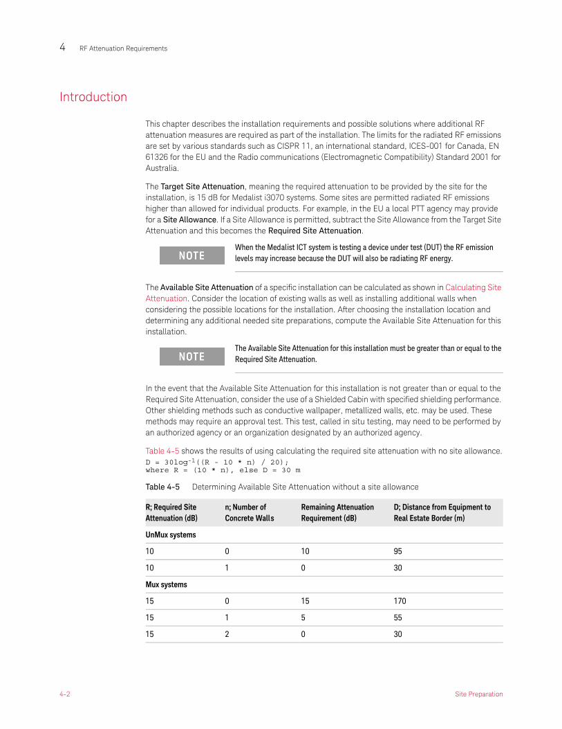
This chapter describes the installation requirements and possible solutions where additional RF attenuation measures are required as part of the installation. The limits for the radiated RF emissions are set by various standards such as CISPR 11, an international standard, ICES-001 for Canada, EN 61326 for the EU and the Radio communications (Electromagnetic Compatibility) Standard 2001 for Australia.
The Target Site Attenuation, meaning the required attenuation to be provided by the site for the installation, is 15 dB for Medalist i3070 systems. Some sites are permitted radiated RF emissions higher than allowed for individual products. For example, in the EU a local PTT agency may provide for a Site Allowance. If a Site Allowance is permitted, subtract the Site Allowance from the Target Site Attenuation and this becomes the Required Site Attenuation.
The Available Site Attenuation of a specific installation can be calculated as shown in Calculating Site Attenuation. Consider the location of existing walls as well as installing additional walls when considering the possible locations for the installation. After choosing the installation location and determining any additional needed site preparations, compute the Available Site Attenuation for this installation.
In the event that the Available Site Attenuation for this installation is not greater than or equal to the Required Site Attenuation, consider the use of a Shielded Cabin with specified shielding performance. Other shielding methods such as conductive wallpaper, metallized walls, etc. may be used. These methods may require an approval test. This test, called in situ testing, may need to be performed by an authorized agency or an organization designated by an authorized agency.
Table 4-5 shows the results of using calculating the required site attenuation with no site allowance.D = 30log-1((R - 10 * n) / 20); where R = (10 * n), else D = 30 m
When the Medalist ICT system is testing a device under test (DUT) the RF emission levels may increase because the DUT will also be radiating RF energy.
The Available Site Attenuation for this installation must be greater than or equal to the Required Site Attenuation.
Table 4-5 Determining Available Site Attenuation without a site allowance
R; Required Site Attenuation (dB)
n; Number of Concrete Walls
Remaining Attenuation Requirement (dB)
D; Distance from Equipment to Real Estate Border (m)
UnMux systems
10 0 10 95
10 1 0 30
Mux systems
15 0 15 170
15 1 5 55
15 2 0 30
4-2 Site Preparation

RF Attenuation Requirements 4
Calculating Site Attenuation
To obtain the necessary attenuation at the installation site you can increase the distance between the equipment and the property boundary or you can add walls or other attenuating structures:
• Required Site Attenuation (R)
R = Target Site Attenuation – Site Allowance
Where:• Target Site Attenuation = 15 dB• Site Allowance for your site = ____________
• The distance from the equipment to the property boundary (D) can be calculated as follows:
D = 30 or 30*log-1((R – n * W)/20) whichever is greater.
Where:• R = Required Site Attenuation• n = Number of concrete walls between equipment and property boundary.• W= Attenuation of the wall (a concrete wall without openings has an attenuation of 10 dB)
• Additional attenuation (X) due to a D greater than 30 meters.
X = 20log(D/30)
Where:• D = distance from equipment to property boundary.
• Total attenuation (A) is calculated as follows:
A = X + n * W
Where:• X = Additional Attenuation• n = Number of concrete walls between equipment and property boundary.• W= Attenuation of the wall (a concrete wall without openings has an attenuation of 10 dB)
Figure 4-3 Determining Available Site Attenuation
Site Preparation 4-3

4 RF Attenuation Requirements
Table 4-6 Determining Available Site Attenuation with a site allowance or a different wall attenuation
Parameter Value
R; Required Site Attenuation (dB)
n; Number of Walls
W; Attenuation per wall
R – n *W ; Remaining Attenuation Requirement (dB)
D; Distance from Equipment to Real Estate Border (m)
4-4 Site Preparation

Keysight i3070 Series 5In-Circuit Test System
Site Preparation
5 Environmental Requirements
Air Quality Requirements 5-2
Air Temperature Requirements 5-3
Humidity Requirements 5-4

5 Environmental Requirements
Air Quality Requirements
As a rule, good air quality is as important for the reliability of your Medalist ICT system as it is for your production process. Three types of airborne contaminants are discussed below. The presence of any of these contaminants at the site will contribute to system degradation, resulting in lower reliability and higher operating costs.
Corrosive Contaminants
Corrosion is a complex form of material deterioration or destruction by chemical or electrochemical reaction. The presence of corrosive contaminants (gases) in the atmosphere is very common in industrial environments. If ignored, corrosion can eventually degrade system performance by its effects on high impedance circuits and low impedance interfaces. It can also deteriorate most plastics including software storage media. The effects of corrosive contaminants are usually accelerated at high humidities or high temperatures.
Corrosives generally cannot be filtered out of the air by normal filtration methods, and the techniques that must be used for their removal are complex and costly. If the source of corrosive contaminants cannot be eliminated, the system should be installed in an enclosed environment with a fresh air supply at positive pressure.
Particulate Contaminants
Particulate contaminants (hard particles) consist of smoke, dust, hair, lint, fibers and miscellaneous organic and inorganic materials. The presence of these contaminants in the air can cause system degradation, especially where disk drives, test fixtures, and low impedance interfaces are concerned. Particulate contaminants can be filtered from the air, and appropriate filters should be included with any air conditioning installation. Also consider installing “No Smoking” signs in the area. Tobacco smoke is a well-known factor in fixture contact contamination. It causes false failures leading to unnecessary DUT repairs and higher production costs.
Viscid Contaminants
Viscid contaminants are oily or sticky airborne substances that can be deposited on the system’s electronic and mechanical parts. Besides contributing directly to system degradation, viscid contaminants collect and hold particulate contaminants and make cleaning very difficult. Viscid contaminants can be removed from the air by filtration, but the elimination of their source, if possible, is preferable.
5-2 Site Preparation

Environmental Requirements 5
Air Temperature Requirements
Table 5-7 summarizes the temperature and cooling requirements for the system. For details, see:
• Air Temperature Specifications
• Cooling Requirements
Air Temperature Specifications
The Medalist ICT system is designed to operate uninterrupted in an area where the air temperature is stable and in the range from 0°C to 40°C (32°F to 104°F), as measured at the tester-to-fixture interface.
The system has a built-in temperature sensor inside the testhead, located on the ASRU card. This sensor constantly monitors the temperature of the air that has been drawn through the testhead after it cools the system components. If the temperature sensor finds that the air temperature inside the testhead has changed ±5°C (±9°F) since the last time the system ran AutoAdjust All, it will run AutoAdjust All again. Therefore, to ensure uninterrupted use, it is important that the ambient room temperature remain reasonably stable.
If the sensor finds that the air temperature inside the system is too high, the system will shut down; typically, the over-temperature shutdown point is 55°C (131°F). See Cooling Requirements for information on air conditioning requirements.
Cooling Requirements
Design the site cooling capability using the heat dissipation estimates in Table 5-8. The numbers are for testheads with fully loaded modules and fully loaded support bays.
Table 5-7 Temperature and humidity ranges for operation and storage
Operating Temperature Operating Humid ity Storage Temperature
Testhead 0°C to 40°C (32°F to 104°F) 5% to 80% non-condensing -40°C to 70°C (-40°F to 158°F)
Support Bay 0°C to 40°C (32°F to 104°F) 5% to 80% non-condensing -40°C to 70°C (-40°F to 158°F)
Controller 5°C to 45°C (41°F to 113°F) 20% to 80% non-condensing -40°C to 65°C (-40°F to 149°F)
The air temperature inside the system is not considered stable until the system has been powered for at least 30 minutes.
Table 5-8 System heat dissipation
Number of Modules Dissipation
1 module 10500 BTU (3.1 kW)
2 modules 19700 BTU (5.8 kW)
3 modules 28500 BTU (8.4 kW)
4 modules 3700 BTU (10.9 kW)
Site Preparation 5-3

5 Environmental Requirements
Humidity Requirements
The system is designed to operate in the range from 5% to 80% relative humidity (non-condensing).
If the system is subjected to condensation, as if moved from a cold loading dock into a warm environment, allow at least 24 hours for the system to recover before powering up.
5-4 Site Preparation

Keysight i3070 Series 5In-Circuit Test System
Site Preparation
6 Power Requirements
Customer Responsibilities 6-2
About the PDU 6-3
Power Requirements 6-4
Is PDU Re-wiring Necessary? 6-9
PDU Wiring Diagrams 6-10

6 Power Requirements
Customer Responsibilities
It is the customer’s responsibility to (a) prepare the site with adequate AC power for the system, and (b) connect the system to the AC power source. These are not Keysight’s responsibilities.
6 Read About the PDU on page 6-3. You must know where the system’s PDU is located to prepare your site.
7 Read Power Requirements on page 6-4. In most cases this section will describe all you need to do to prepare your site.
8 If you are connecting the system to a different power configuration than it is wired for, read Is PDU Re-wiring Necessary? on page 6-9.
After connecting power to the system, do not power up the system. A Keysight service representative will verify the power and complete the system installation and verification.
6-2 Site Preparation

Power Requirements 6
About the PDU
The testhead product number and serial number are located on the rear of the testhead cradle. Figure 6-4 and Figure 6-5 show rear views of the systems.
The PDU (Power Distribution Unit) is the device in the system to which you will connect AC power.
The PDU is wired differently for different power configurations. The voltage of the PDU is marked on the front panel of the PDU. If you install a system in a location in which the actual power does not match the power configuration of the PDU, you may need to rewire the outlet connections in the PDU (see Is PDU Re-wiring Necessary? on page 6-9).
Figure 6-4 Rear views of the UnMux system
Figure 6-5 Rear views of the Mux system
��������� ���
��� �
��� �
����
���
������������� ���
�������������
��� ���� � ��� �
��� �
����
���
������������ ��!��"����" ����#� �"���$�� �!��� ����%�&�
&�##� ���������"�
��������� ���#� � �""�� ��'
�������������
��� ���� � ��� �
��� �
����
���
�������������
��������� ���
��� �
��� �
����
���
��������� ���
�������������
��� ���� � ��� �
��� �
����
���
Site Preparation 6-3

6 Power Requirements
Power Requirements
• Mains Disconnect• Power Drop• Basic Power Quality Survey• Connecting Power to the PDU
Mains Disconnect
A mains disconnect — providing over-current and short-circuit protection — must be provided for the system. It may be a fused disconnect or a circuit breaker (see Figure 6-6).
If a fused disconnect is used, it must:
• Be rated for 30 amps in each phase.
• Open all line conductors and neutral conductors where local code applies, but not the protective earth conductor.
• Be marked “System Mains Disconnect” or the equivalent in your local language
• Be marked with a “|” for the “On” position or “O” for the “Off” position.
• Be capable of being locked in the “Off” position, but not in the “On” position.
• Be installed within 3 meters of the system, where it can be easily reached by the system operator without requiring the system to be moved to access the disconnect.
If a circuit breaker is used, it must meet all of the above requirements plus:
• Be rated for a minimum of 10,000 amps interrupting capacity (AIC) if used on a 200–240 volt circuit, or 14,000 AIC if used on a higher voltage circuit.
Figure 6-6 Wiring diagram
'� �
(����� ���)���*���
���
+($�� �!�����
��#���" ������"�#�����,������
-�� ��������� � ���� ������� ����.
(�� ������� ����"�#����"�����" ���
�������������
&�� �!������� �"�#���" ��������/#� � ��'� ���/��� 0123/���3�,�������4
6-4 Site Preparation

Power Requirements 6
Power Drop
• A dedicated power drop must be provided for the testhead due to its high current requirements.
• Copper wire must be used for the power drop.
• An electrician must determine the wire size for the power drop. The wires must be sized to ensure that the voltage at the system does not drop below 90 percent of nominal (see Calculating the Minimum Voltage on page 6-5).
• Convenience outlets should be provided near the system for external equipment such as programming stations, extra equipment bays, and automation equipment. Locate the outlets within one meter (three feet) of the rear of the system. See Chapter 2, Planning to plan the location of convenience outlets. Convenience outlets should supply current protection at 15A or 20A depending on local code requirements at 100–120 volts or current protected at 10A depending on the local code requirements at 200–240 volts.
Calculating the Minimum Voltage
The voltage at the testhead must be at least 90 percent of nominal. To calculate the minimum rms voltage multiply the rms voltage by 0.9. To calculate the minimum peak voltage, multiply the rms voltage by 0.9 and then 1.414. For example:
208 volts rms * 0.9 * 1.414 = 265 volts peak
Site Preparation 6-5

6 Power Requirements
Sizing the Input Wires and Circuit Breakers
Table 6-9 shows the full-load amps (FLA) for each system type.
Table 6-9 Power requirements
PDU Power Option
Frequency Vol tage l ine-to-neut / l ine-to-l ine
Full-Load Amps (FLA) for:
1-module system
2-module system
4-module system
200–240V 3-Phase Del ta 3PD 50/60 hertz 200
220
230
240
13
13
13
13
18
18
18
18
24
24
24
24
208–220V 3-Phase Wye 3PY 50/60 hertz 208
220
13
13
18
18
24
24
380–415V 3-Phase Wye with Neutral
3PN 50/60 hertz 220 / 380
230 / 400
240 / 415
9
9
9
10
10
10
16
16
16
5�
5�
5�
6
7��" ������
5�
5� 5�6
7��" ������
5�
5� 5�6
7
Neutral is not used by the systems for power options 3PD and 3PY. Neutral is shown in the diagrams because Neutral is cabled into the PDU.
6-6 Site Preparation

Power Requirements 6
Basic Power Quality Survey
Power quality can affect system performance differently. The following procedure is intended as a guideline and may not be the total solution. Failure to meet these guidelines should serve as an indicator that a power quality consultant might be needed to conduct a more in-depth power quality survey.
1 With the system operating, measure harmonic distortion at the system-input connection. THD should be less than 5% and less than 3% for any single harmonic.
2 With the system operating, measure the ground-to-neutral voltage at the system-input connection; the voltage should be less than 4vp-p.
3 Turn the system power off and measure the line voltage at the system-input connection; record this reading. Turn the system on and begin operating mode. Measure the line voltage at the system-input connection again. The difference between the two measurements should be less than 2%.
Other problematic power qualities include momentary voltage interruptions, ground noise, and voltage spikes. A survey of these problems and others may require the services of a power quality expert with specialized equipment.
Connecting Power to the PDU
One of two different power cords and plugs are attached to the PDU depending on the country where the system will be installed.
Table 6-10 Power cord and plugs
International North America
Uses 5 x 6 mm2 5-conductor cord with a IEC 60309 plug and mating receptacle. See Figure 6-7 on page 6-8.
Uses #10 AWG 5-conductor cord with NEMA plug that mates with NEMA L21-30. See Figure 6-8 on page 6-8. The female receptacle is available locally.
Site Preparation 6-7

6 Power Requirements
Figure 6-7 International 3-phase systems
Figure 6-8 North American 3-phase systems
+(&�� �! ����
�48��84�, ��,9��+:6%������� �� ;����4(�����������" �0���""���0'+!��� 4
��+<����0��)��� ����+,���
'� �
���
&�� �!������� "�#���" ��������/#� ��'� ���/������0123 ����3�,�������4
��#�����#� �,�����" �����""���0'��� ���
(����� ��������$����.������������#� ����������
���0���������0�"�� � �������� ������,������� �$�� ���4
6-8 Site Preparation

Power Requirements 6
Is PDU Re-wiring Necessary?
Re-wiring the PDU is necessary only if you are connecting it to a different power configuration than it was wired for, not merely a different voltage. Delta (3PD) and Wye (3PY) are equivalent configurations.
See Table 6-11 and the examples below.
Suppose your system’s PDU is wired for 220 volts wye (option 3PY) and you want to connect it to:
1 208 volts wye (option 3PY)
No re-wiring is necessary; this is merely a voltage change and all internal components will handle 200 to 240 volts.
2 220 volts delta (option 3PD)
No re-wiring is necessary; options 3PY and 3PD have the same internal wiring.
3 220 volts wye with neutral (opt 3PN)
Re-wiring is necessary because the internal circuits are wired phase-to-phase and the internal components would experience over-voltage. Whenever you switch from a non-neutral to a neutral configuration, or vice versa, you must re-wire the PDU.
1. Regardless of the power option, the internal system components always operate at 200–240 volts.
If you determine that re-wiring the PDU is necessary, see PDU Wiring Diagrams on page 6-10.
Table 6-11 Power Options / Configurations
Power Options Configuration Description1
3PD 200–240 volts 3-phase Delta (50/60Hz)Includes 200V, 220V, 230V, 240V
3PY 208–220 volts 3-phase Wye (50/60Hz)Includes 208V, 220V
3PN 380–415 volts 3-phase Wye with Neutral (50/60Hz)Includes 380V, 400V, 415V
Site Preparation 6-9

6 Power Requirements
PDU Wiring Diagrams
Table 6-12 PDU wiring diagram
PDU Power Option
Vol tage l ine-to-neut / l ine-to-line
Testhead Outlet Locations
1-module 2-module 4-module
Outlet Locations Figure 6-9 on page 6-11
Figure 6-14 on page 6-14
Figure 6-19 on page 6-17
200–240V 3-Phase Del ta 3PD 200 220 230 240
Figure 6-10 on page 6-12
Figure 6-15 on page 6-15
UnMux systems:Figure 6-20 on page 6-18
Mux systems:Figure 6-24 on page 6-22,Figure 6-26 on page 6-23
208–220V 3-Phase Wye 3PY 120 / 208 127 / 220
Figure 6-10 on page 6-12
Figure 6-15 on page 6-15
UnMux systems:Figure 6-20 on page 6-18
Mux systems:Figure 6-24 on page 6-22,Figure 6-26 on page 6-23
380–415V 3-Phase Wye with Neutral
3PN 220 / 380 230 / 400 240 / 415
Figure 6-12 on page 6-13
Figure 6-17 on page 6-16
UnMux systems:Figure 6-22 on page 6-20
Mux systems:Figure 6-27 on page 6-24Figure 6-29 on page 6-25
6-10 Site Preparation

Power Requirements 6
One-Module System AC Outlets
Figure 6-9 One-Module System
Outlet 2 Outlet 3
Outlet 1
PDU
Testhead (Rear View)
Site Preparation 6-11

6 Power Requirements
Figure 6-10 One-Module System Options 3PY, 3PD
Figure 6-11 One-Module System Options 3PY, 3PD
��"� ��#���,���� ���;" ���
��=
���
&+(�����8������������
*5+������������
������
�
���
���
���
���
��
��
��
��
��
��
��
��
��
��
�
�
��
�%
�
%
2
>
8
?
��
��
��
��
(��
(��
(��
(��
(�%
(�2
(�>
(�8
(�?
(���
6@76@76@7
�@7
�@7
�@7
�5�
�5�
�5�
A�4%BA�42(�� ��������
-�;
;� � ��C9��������
;� � ��C9��@���� ��
;� � ��C9��@���
�
��
�
�
��
�
�
��
�
�
��
�
��
�
��
�
�
��
�
�
��
(�� ��������"��'
( �
��"���� �
5+7D�0� ���*��
���#� ���
������ (����� ����� �"�,6�����0���)������ (����� ����� �"�,55�0���)������ (����� ����� �"�,55�0���)
5�
5�
5�
5���5�B5�5�B5�5�B5�
6
5�
5�
5��������
+(�������"� ����<"��!"��$���
5� 5� 5� 7
5� 5� 5� 7�� ��� ��� �
��+ ��+
7� ����,��������� ������� ������4���� ��$4
�
��,��� ������
����� ������
6(������6�����
�� �����!��-���%(@$�
���� ��
�� ��� �����
������
������
�����
������
(�� ���0����A�4�A�4�
;� � ��C9��������
;� � ��C9��@���� ��
*����� ��
#� �����#�;� � � #� �����#�;� � �
;� � ��C9��@���
���� 9�
���� 9�
#� �����#�;� � �
���
1��&<1%&� ���� 9�
6-12 Site Preparation
Power Requirements 6
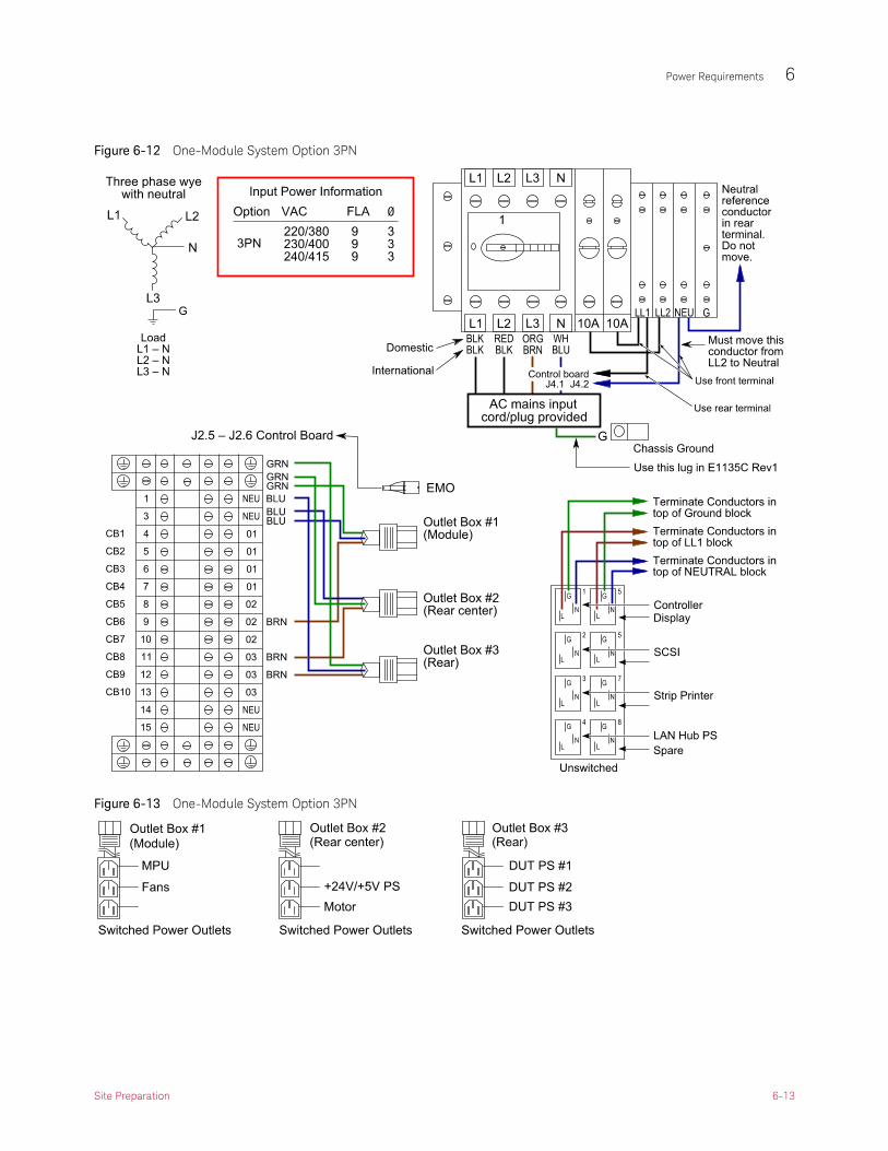
Figure 6-12 One-Module System Option 3PN
Figure 6-13 One-Module System Option 3PN
Site Preparation 6-13

6 Power Requirements
Two-Module System AC Outlets
Figure 6-14 Two-Module System
Outlet 0
Outlet 3Outlet 1
PDU
Testhead (Rear View)
Outlet 2
6-14 Site Preparation

Power Requirements 6
Figure 6-15 Two-Module System Options 3PY, 3PD
Figure 6-16 Two-Module System Options 3PY, 3PD
Site Preparation 6-15

6 Power Requirements
Figure 6-17 Two-Module System Option 3PN
Figure 6-18 Two-Module System Option 3PN
6-16 Site Preparation
Power Requirements 6
Four-Module System AC Outlets
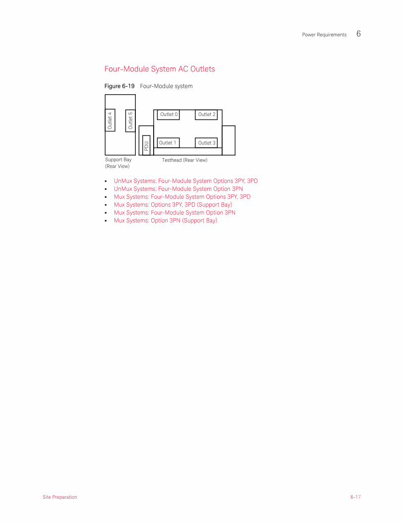
Figure 6-19 Four-Module system
• UnMux Systems: Four-Module System Options 3PY, 3PD• UnMux Systems: Four-Module System Option 3PN• Mux Systems: Four-Module System Options 3PY, 3PD• Mux Systems: Options 3PY, 3PD (Support Bay)• Mux Systems: Four-Module System Option 3PN• Mux Systems: Option 3PN (Support Bay)
Outlet 0
Outlet 1PD
U
Testhead (Rear View)
Outlet 2
Outlet 3
Out
let
4
Out
let
5
Support Bay(Rear View)
Site Preparation 6-17

6 Power Requirements
Figure 6-20 UnMux Systems: Four-Module System Options 3PY, 3PD
6-18 Site Preparation

Power Requirements 6
Figure 6-21 UnMux Systems: Four-Module System Options 3PY, 3PD
Site Preparation 6-19
6 Power Requirements
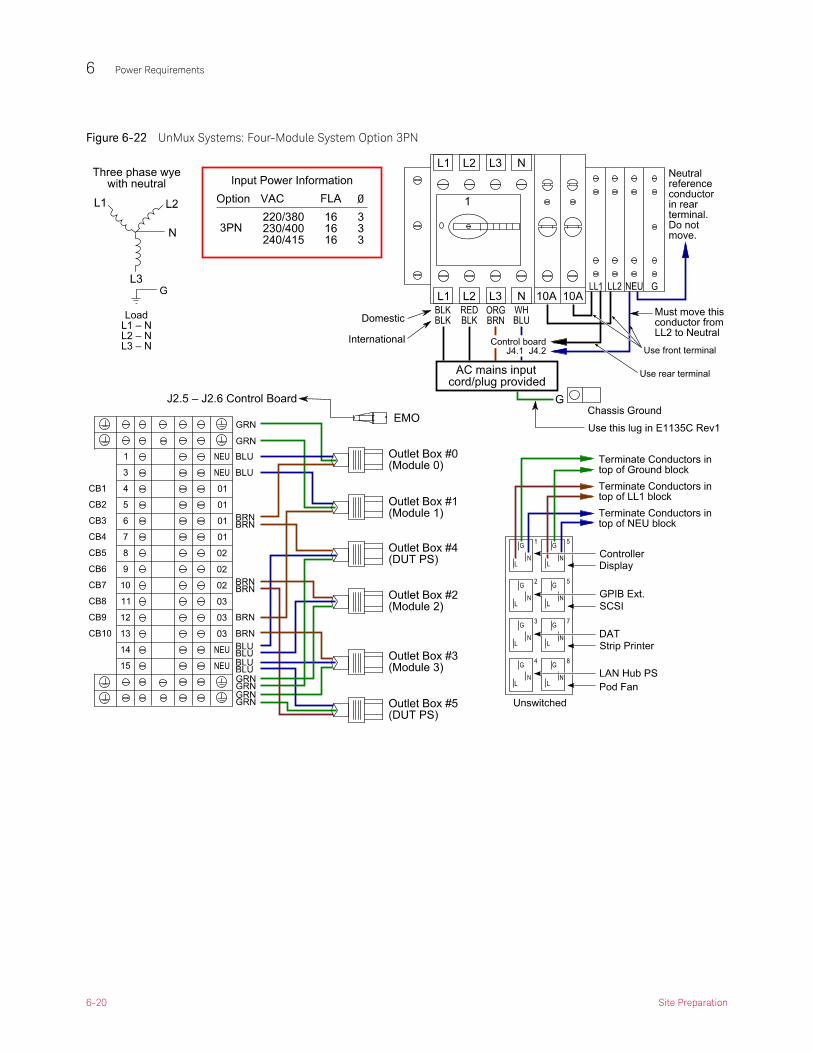
Figure 6-22 UnMux Systems: Four-Module System Option 3PN
6-20 Site Preparation

Power Requirements 6
Figure 6-23 UnMux Systems: Four-Module System Option 3PN
Site Preparation 6-21

6 Power Requirements
Figure 6-24 Mux Systems: Four-Module System Options 3PY, 3PD
Figure 6-25 Mux Systems: Four-Module System Options 3PY, 3PD
6-22 Site Preparation

Power Requirements 6
Figure 6-26 Mux Systems: Options 3PY, 3PD (Support Bay)
Site Preparation 6-23
6 Power Requirements
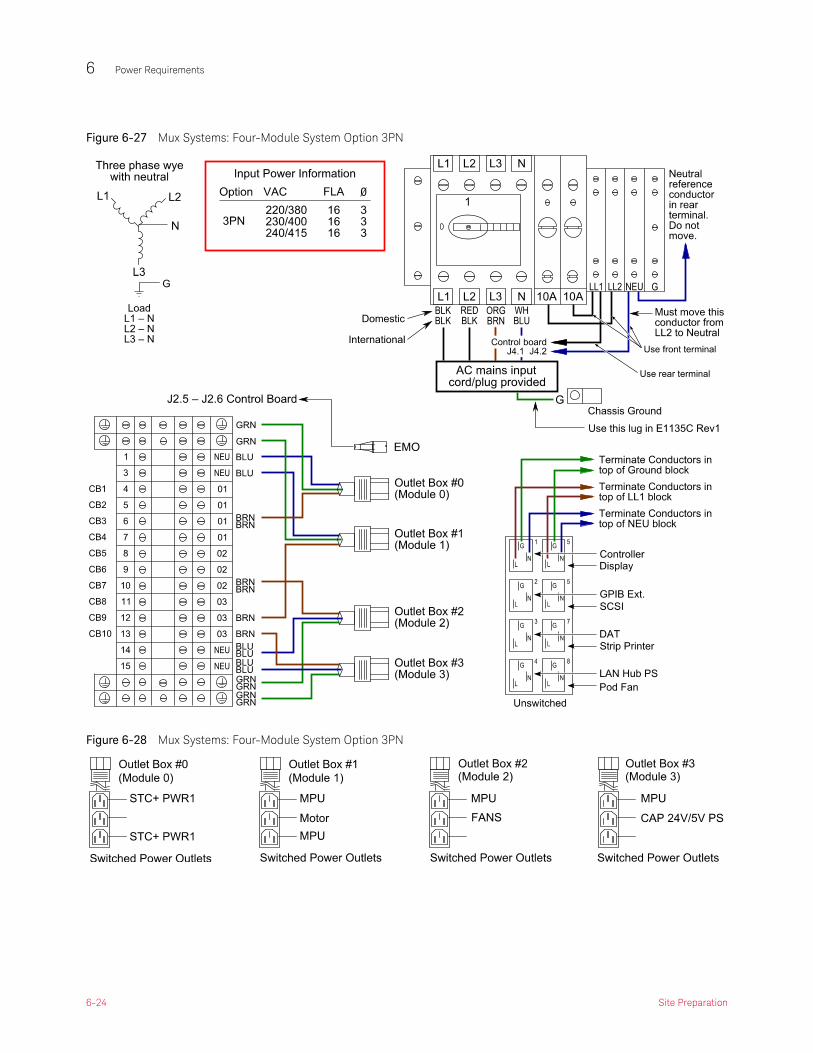
Figure 6-27 Mux Systems: Four-Module System Option 3PN
Figure 6-28 Mux Systems: Four-Module System Option 3PN
6-24 Site Preparation
Power Requirements 6
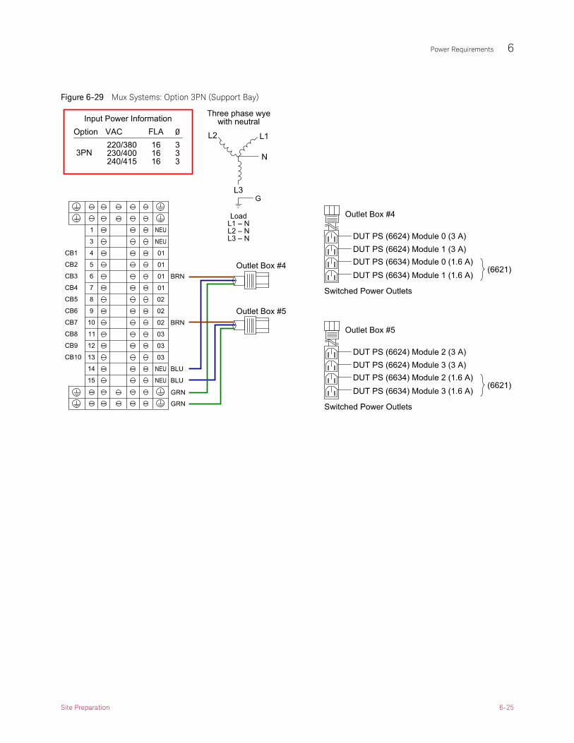
Figure 6-29 Mux Systems: Option 3PN (Support Bay)
Site Preparation 6-25

6 Power Requirements
6-26 Site Preparation

Keysight i3070 Series 5In-Circuit Test System
Site Preparation
7 Compressed Air and Vacuum Requirements
Introduction 7-2
Compressed Air Requirements 7-3
Vacuum Requirements 7-5
Compressed Air and Vacuum Primer 7-7
7 Compressed Air and Vacuum Requirements
Introduction
Both compressed (or pressurized) air and vacuum are used in the testhead. Compressed air is used primarily to secure the test fixture to the testhead. Vacuum is used primarily to actuate the test fixture: that is, to make contact between the board under test and the probes in the fixture. Compressed air is sometimes also used for air-assisted, solenoid-actuated valves used to switch the vacuum, and for air-actuated test fixtures.
The site preparation requirements for compressed air and vacuum are different depending on the type of testhead you are preparing the site for. This chapter describes those requirements.
For more about compressed air and vacuum principles and terminology, see the short Compressed Air and Vacuum Primer on page 7-7.
7-2 Site Preparation

Compressed Air and Vacuum Requirements 7
Compressed Air Requirements
The i3070 uses compressed air to pressurize air cylinders that actuate fixture pull-down towers. Pull-down towers are used to pull and hold a fixture down onto the testhead, enabling contact between the pins on the fixture and the spring-loaded interface pins in the testhead.
• Connecting Air to the Testhead
• Compressed Air Specifications
• Air Quality
Connecting Air to the Testhead
Install compressed air lines using rigid line to a point near the testhead. An air cutoff valve is recommended for situations when the air line must be disconnected.
When the system is installed, connect the air to the testhead with a flexible line that has a Hansen Series 3000 Push-tite 1/4-inch female coupling or equivalent. The testhead air input connector is shown in Figure 7-30.
Figure 7-30 Compressed air connection to the testhead
Site Preparation 7-3
7 Compressed Air and Vacuum Requirements
Compressed Air Specifications
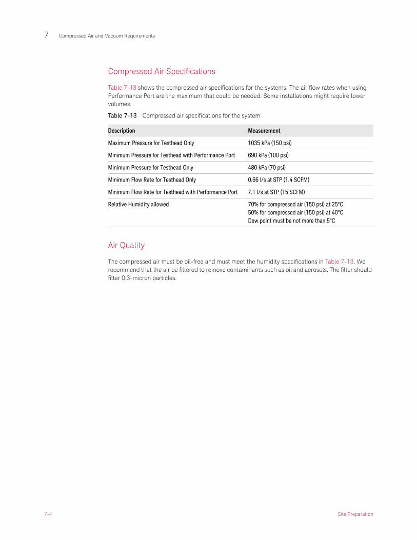
Table 7-13 shows the compressed air specifications for the systems. The air flow rates when using Performance Port are the maximum that could be needed. Some installations might require lower volumes.
Air Quality
The compressed air must be oil-free and must meet the humidity specifications in Table 7-13. We recommend that the air be filtered to remove contaminants such as oil and aerosols. The filter should filter 0.3-micron particles.
Table 7-13 Compressed air specifications for the system
Description Measurement
Maximum Pressure for Testhead Only 1035 kPa (150 psi)
Minimum Pressure for Testhead with Performance Port 690 kPa (100 psi)
Minimum Pressure for Testhead Only 480 kPa (70 psi)
Minimum Flow Rate for Testhead Only 0.66 l/s at STP (1.4 SCFM)
Minimum Flow Rate for Testhead with Performance Port 7.1 l/s at STP (15 SCFM)
Relative Humidity allowed 70% for compressed air (150 psi) at 25°C50% for compressed air (150 psi) at 40°CDew point must be not more than 5°C
7-4 Site Preparation

Compressed Air and Vacuum Requirements 7
Vacuum Requirements
The i3070 uses vacuum (with vacuum-actuated test fixtures) to pull the board under test down onto test probes. Because of the different sizes of test systems, test fixtures, and the variety of boards that can be tested, vacuum requirements can vary significantly.
Keysight recommends that you work with a qualified vendor of vacuum pumps who can give you advice based on your requirements.
• Vacuum Recommendations and Guidelines
• Connecting Vacuum to the Testhead
Vacuum Recommendations and Guidelines
Table 7-14 shows the vacuum recommendations for a typical system.
Vacuum Guidelines
Keep these additional guidelines in mind as you design your system:
• Use the largest diameter of pipe practical from the vacuum pump to the testhead area. This diminishes vacuum loss due to friction in the piping (especially at bends), and provides a demand reservoir.
• Keysight also recommends that a filter be installed between the vacuum supply and the testhead to prevent dirt or contaminants from being sucked through the test fixture into the vacuum supply.
• Pressure meters, flow meter, and filters are optional but recommended.
• If the vacuum manifold is used, a 2-inch vacuum hose should be used. If vacuum ports are connected individually, a 1-inch vacuum hose must be used.
Table 7-14 Vacuum recommendations for the system
Description Measurement
Recommended Flow Rate of Pump 18.9 l/s at STP (40 SCFM) Use this value as a guideline. Vacuum specification is dependent on the fixture, not the testhead. Keysight has found this specification will pull down most fixtures.
Pressure Performance 50 kPa (7.2 psi)
Vacuum Control Ports available for controlling external vacuum valves
4 vacuum control ports: switched 24 volts DC, 750 milliamps maximum per port
Vacuum pumps installed for the tester should be installed outside or vented outside in order to prevent the vacuum pump from exhausting oil-bearing air or carbon fragments in areas where there are people.
Site Preparation 7-5

7 Compressed Air and Vacuum Requirements
Connecting Vacuum to the Testhead
Figure 7-31 shows the vacuum port locations on the system. The vacuum manifolds shown are optional.
Figure 7-31 Vacuum port locations
Large vacuummanifold
Small vacuummanifold
7-6 Site Preparation

Compressed Air and Vacuum Requirements 7
Compressed Air and Vacuum Primer
There are two key concepts involved in understanding the compressed air and vacuum requirements for the i3070. The first is pressure and the second is flow rate.
Pressure is the force per unit area that a gas exerts on a surface. If zero is used as a reference, the measurement of pressure is called “absolute”; if the local atmospheric pressure is used as a reference, the measurement is called “gage.” Although atmospheric pressure varies with altitude and weather, gage pressure is typically used for engineering measurements, so it is used in this manual. A pressure value below zero gage is considered a vacuum.
Common units for measuring pressure are kilopascals (kPa), pounds per square inch (psi), and atmospheres (atm).
Flow rate is the quantity of a gas moving through a given area per unit of time. Since air is compressible, you must know both the speed and pressure of the air when measuring the flow rate. To reduce confusion, the industry has agreed on a standard set of conditions for flow rate measurements called “standard temperature and pressure” (STP). The standard temperature is 0°C (32°F), and the standard pressure is one atmosphere (101.3 kPa or 14.7 psi).
Common units for measuring flow rate are liters per second (l/s) and cubic feet per minute (CFM). When using standard conditions, the units are written as “l/s at STP” or “SCFM” (standard cubic feet per minute).
Compressed Air
The i3070 uses compressed air to activate both the fixture pull-down towers and the vacuum valves. The system also provides an outlet for supplying air to accessory equipment such as handlers and air assisted fixtures.
The minimum pressure needed is 480 kPa (70 psi). The system has an internal regulator to restrict the maximum pressure inside the system to 550 kPa (80 psi).
The flow rate needed is dependent on how often fixtures are changed, but is generally much less than what is available in most production areas. Additional air (flow rate) may be needed to supply the outlet for custom fixtures or presses depending on their requirements.
Site Preparation 7-7

7 Compressed Air and Vacuum Requirements
Vacuum
The system doesn’t use vacuum directly. Rather, the vacuum is used by the fixture to pull a device under test (DUT) onto the probes. The system provides valves, plumbing and control to assist in supplying vacuum to the customer’s fixture.
The pressure requirements for vacuum come from the need to compress the probes, fixture springs and seals. Since most commercial vacuum systems operate around 50 kPa (7.5 psi), vacuum fixtures are limited in their ability to handle DUTs with high probe densities. If the sum of the probe, spring and seal forces divided by the area of the DUT is above 48 kPa (7 psi) the fixture will not be able to properly pull the DUT onto the probes.
The flow requirements for vacuum come from fixture leaks, number of fixture cycles per minute, the size of the DUT and the need to quickly evacuate the fixture to make a good seal around the DUT. Due to the variability of these factors, it is difficult to provide an exact flow rate recommendation. Keysight has found that a flow rate of 19 l/s (40 SCFM) will pull down most fixtures.
7-8 Site Preparation

Keysight i3070 Series 5In-Circuit Test System
Site Preparation
8 Receiving and Moving Instructions
Inventory the Shipment 8-2
Uncrating the System and Support Bay 8-3
Placing the System 8-4
Re-shipping a System 8-5

8 Receiving and Moving Instructions
Inventory the Shipment
Use the packing list that came with your system to determine if the system was fully received. Carefully examine the boxes for shipping damage. If you suspect the system was damaged in shipment, contact your Keysight representative.
8-2 Site Preparation

Receiving and Moving Instructions 8
Uncrating the System and Support Bay
The customer should remove the tri-wall box from the pallet. The Keysight representative will uncrate the system pallets. Leave the smaller boxes intact for the Keysight representative to unpack when the system is installed.
Follow the uncrating instructions in Uncrating the i3070.
Site Preparation 8-3

8 Receiving and Moving Instructions
Placing the System
Moving the Testhead and Support Bay
Make sure all leveling feet are turned up as high as they go before rolling the system.
Place the system exactly as the system plan drawing shows. Remember that the testhead will be rotated up for service and that cable length will be critical.
Immobilizing and Leveling the System
Immobilize and level all bays by screwing the leveling feet down to the floor. The testhead may be difficult to unlock or rotate if it is not level.
If local building codes require equipment to be anchored to the floor due to potential seismic activity (earthquakes), you will need to bolt the system to the floor. The shipping brackets used to secure the system to the pallet are suitable for this purpose, but you will need to supply fasteners suitable for your situation.
8-4 Site Preparation

Receiving and Moving Instructions 8
Re-shipping a System
When it becomes necessary to pack and ship a system to another location, Keysight can help. You can either purchase a Keysight Move, which includes Keysight personnel disassembling, packing, shipping, and setting up the system at the new location; or you can purchase a shipping kit from Keysight which includes the pallet and other materials required to ship a system.
See “Re-Shipping Kits” under Parts in the online help for the shipping kit part numbers.
When re-shipping a support or instrument bay, do not use the ramp to move the bay onto the pallet to avoid possible injury due to the bay tipping over on you. The ramp is designed for removal of the bay only. Instead, use a hoist and attach to the hooks on the top of the bay and l ift the bay onto the pallet.
Site Preparation 8-5