Kessler-Ellis Products • 800-631-2165 Flow Instruments • 1 · 2014-09-06 · Kessler-Ellis...
121
Transcript of Kessler-Ellis Products • 800-631-2165 Flow Instruments • 1 · 2014-09-06 · Kessler-Ellis...


Kessler-Ellis Products • 800-631-2165 Flow Instruments • 1
INDEX
INTRODUCTION PAGE DESCRIPTIONKEP Company Overview 3 A brief history of our company.
COMPARISON TABLES PAGE DESCRIPTIONProduct vs. Flow Meter 4 Product comparison based on flowmeter compatibilityCompatibility TableProduct vs. Feature Table 5 Product comparison based on feature availability
SIGNAL CONDITIONERS PAGE DESCRIPTIONSignal Conditioners Tutorial 6 A quick overview for signal conditioners.SC-FI 7 Frequency to current signal conditioner.SC-II 9 Current to current isolator.SC-IF 11 Current to frequency loop powered isolator.SC-FF 13 Frequency to frequency pulse isolator and scaler.
PROCESS, LEVEL & TEMP. MONITORS PAGE DESCRIPTIONProcess & Level Monitors Tutorial 15 A quick overview for process and level monitors.TP550 Series 16 Temperature/process monitor with or without alarms.INTELLECT-69PM2 18 Analog input, LED, panel meter with relays & 4-20mA output.SQUIRT-R 20 Loop powered indicator with LCD display.LEVELtrol II 22 Multi-Function Level Indicator and Controller.529K 37 LED, Miniature, Analog Input Rate/Process Indicator.
FIELD INDICATORS PAGE DESCRIPTIONField Indicators Tutorial 24 A quick overview for field indicators.SQUIRT 25 Loop powered Ratemeter / Totalizer with LCD display.BAT R/T 28 Battery powered Ratemeter / Totalizer with LCD display and 10
point Linearization.BAT RAT 31 Special version of the BAT R/T with transistor alarm output.BAT D/T 33 Special version of the BAT R/T with dual totalizer display.
RATEMETER / TOTALIZERS PAGE DESCRIPTIONRate / Total Tutorial 36 A quick overview for rate / total monitors.525K, 529K & 530K 37 LED, Miniature, Pulse and Analog Input Rate and Total IndicatorINTELLECT69 38 LED, 1/8 DIN, Analog Input Ratemeter / Totalizer with scaling
and relays.MINITROL 40 LED, 1/8 DIN, pulse input, Ratemeter / Totalizer with scaling and
relays.MINITROL-S 43 Special version of the MRT with separate scaling for rate and
total.MINITROL-PW 45 Special version of the MRT for use with paddle or pelton wheel
turbine flowmeters.DRT 47 Separate Dual Ratemeter and Totalizer with Combination
Function.SUPERtrol ILE 49 Rate/Total indicator for pulse inputs.SUPERtrol-I 61 Rate/Total indicator with pulse or analog inputs.
Performs Volumetric, Mass or Corrected Volume batching.KEPtrol R/T 51 8 Digit, LED, Scalable Ratemeter / Totalizer with Pulse or
Analog Inputs.MS-716 54 Flow Totalizer, Ratemeter and Batcher for Vehicle & Skid
Mounting.
Help
Click on the product you wish to view. Hidden links are active on this page.

2 • Flow Instruments Kessler-Ellis Products • 800-631-2165
BATCHERS PAGE DESCRIPTIONBatcher Tutorial 58 A quick overview for batchers.MINIBATCHER 59 Low cost, miniature batch controller with pulse input.SUPERtrol ILE 49 Batch controller indicator for pulse inputs.SUPERtrol-I 61 Batch controller indicator with pulse or analog inputs.
Performs Volumetric, Mass or Corrected Volume batching.BATCHtrol II 64 Batch controller with pulse or analog inputs.
FLOW COMPUTERS PAGE DESCRIPTIONFlow Computer Tutorial 67 A quick overview for flow computers.SUPERtrol-I 61 Batch controller, Rate/Total indicator with pulse or analog
inputs.Performs Volumetric, Mass or Corrected Volume batching.
SUPERtrol-II 69 Multifunction flow computer, compensates steam, gases andliquid for temperature & pressure to yield Volumetric, Mass &Heat Flow.
MS-748 72 Rugged, Field Mount, Multi-Function Flow Computer.MS-747 76 Flow Computer for Liquid and Gas Applications.MASStrol 80 Mass flow computer, compensates steam, gases and liquids
for temperature and pressure to yield Volumetric, Mass & HeatFlow.
DPFC 83 Differential pressure flow computer, used for stacked DPconfigurations, compensates steam, gases and liquids fortemperature and pressure to yield Volumetric, Mass & HeatFlow.
COMMUNICATION SOLUTIONS PAGE DESCRIPTIONCommunication Solutions Tutorial 86 A quick overview for communication solutions.KEPServer (KEPS-KEP1-32) 87 SUPERtrol series 32 bit device driver for KEPware's DDE
Server.EPS3000 88 Intelligent Ethernet Port Server.CA-285 89 RS-422/485 to RS-232 Interface Converter.MPP-2400 90 Port Powered Modem, 2400 Baud Rate.MS-722 91 Wall Mount Port Powered Modem.MPP-2400N 92 Port Powered Modem, 2400 Baud Rate in NEMA4 enclosure.TWP 93 Industrial Two Way Pager Wireless Data Transceiver.
FACTORY AUTOMATION& Industrial PC's PAGE DESCRIPTIONFactory Automation Tutorial 94 A quick overview for factory automation.Infilink-HMI 95 Industrial Automation Software.KEPServerEX 98 OPC/DDE Server Software.AMB Industrial PC's 99 Industrial panel PC's with flat-panel display, Models AMB-513,
AMB-541, AMB-655, AMB-2000/2020, AMB-2053, MMI-3000.
SPECIAL FLOW INSTRUMENTS PAGE DESCRIPTIONFLOWtrol 111 Batch Controller with DPDT relays.KEPtrol F/C 111 Net rate & total display, ideal for net flow of boiler or diesel fuel.MASSBATCH 112 Batch controller with Temperature or Density Compensation.
ACCESSORIES PAGE DESCRIPTIONXTROL 7/4 113 Explosion proof housing for standard 'trol products.XHV 115 Explosion proof housing for viewing displays (Supertrols, MRT,
INT69, etc) in hazardous areas.NEMATROL 116 Wall mountable NEMA 4X Enclosures.P1000 117 Table top / hand held serial printer.P295 118 Miniature Slip Printer.115 Series 119 5, 12 and 24 VDC power supplies with 115 or 230 VAC input.AMP-1 119 Preamp and signal conditioner for magnetic pickups.SPARE PARTS 120 Various retrofit boards, IC chips, fuses and spare parts.
INDEX(continued)
Help
Click on the product you wish to view. Hidden links are active on this page.

Kessler-Ellis Products • 800-631-2165 Flow Instruments • 3
IntroductionKessler Ellis Products has manufacturing facili-ties located in Eatontown, New Jersey. KEP hasbeen supplying display and instrumentation prod-ucts since it was founded in 1960. In the early 80’s,KEP broadened its product line to include flowmeasurement instrumentation. As the market forinstrumentation continued to evolve, product of-ferings grew to include industrial automation, com-munication server software, communications ac-cessories, and Industrial PC’s.
PeopleKEP team members have consistently shown anobsessive concern about our customers for thelast 40 years. We work hard to offer you solutionsthat solve your problems and service your needs.We take that extra step to ensure complete cus-tomer satisfaction.
Flow Measurement CommunityKEP seeks to service the flow measurement com-munity by providing versatile, economical instru-mentation and “know how” to our users. Our goalis to enable you to select a suitable instrumentfrom our offerings for use with a flowmeter se-lected from any supplier of your choice from thebroad range of flowmeter types and suppliers onthe market today.
Flowmeter CompatibilityThere are a large number of flowmeter types inthe market which are compatible with our line ofinstruments. These include: Coriolis, magnetic,nozzle, open-channel, orifice, pitot/annubar, posi-tive displacement, rotometers, thermal mass, tur-bine, venturi, and vortex. Our flow instrumentsalso operate with many proprietary flowmetertypes.
Applications AssistanceKEP has a large number of applications engi-neers to assist you in selecting the most appro-priate instrument for your application. Our appli-cation engineers can provide the detailed “knowhow” necessary to setup each instrument and toassist in the electrical interconnection betweenthe flowmeter and the instrument.
Special ConfigurationsIn addition to the standard products listed in thiscatalog, KEP offers in house engineering capa-bilities to customize the products and enclosuresto meet the special needs of customers. Pleasecontact us with you requirements.
Selection GuidesThe pages which follow include two selectionguides. The first is a preliminary selection guide tohelp you select several instruments that appearsuitable for use with your flowmeter type andperform the intended instrument functions. Thesecond selection guide contains a feature grid tohelp you make your final selection.
If you are unfamiliar with some aspect of theequipment selection or utilization, please reviewthe tutorials that appear at the start of eachsection. These include answers to the most fre-quently asked questions we encounter while as-sisting customers.
Web SiteVisit our web site (www.kep.com) for the latestdatasheets, user manuals, setup software, appli-cation notes and other vital information.
KEP Company Overview

4 • Flow Instruments Kessler-Ellis Products • 800-631-2165
Product vs. Flow Meter Compatibility Table
MASSBATCH
SQUIRT,
SQUIRT-
R
BAT R/T,
RAT &
D/T
INT-
69 /
INT-
69PM
2
MIN
ITROL,
PW
& S
KEPTROL R/T
BATCHTROL II
MASSTROL /
DPFC
Coriolis
Differential Producers:
Venturi
V-Cone
Flow Nozzle
Wedge
Elbow
Orifice
Pitot / Annubar
Magnetic
Positive Displacement
Propeller (turbo)
Roto Meter (Variable Area)
Target
Turbine (paddle wheel & Insertion)
Thermal
Ultrasonic
Vortex
Open Channel Weirs & Flumes
ILVA / GilFlo
2 1 2 1 1,2
* *, 3 *, 3 *, 3 *
2 * * * * * *
2 * * * * *
2, 4 2, 4 2, 4
* *, 3 *, 3 *, 3 *, 3
2 * * * * *
* * *, 2 *, 2
2 1 2 1 1 1 1
2 * 2 * * * * *
2, 4 2, 4 2, 4
2 1 2 1 1, 2 1, 2 1 *
Flow Meter Type
Flow IndicatorsRate & Totalizers
FlowBatch Controllers
FlowComputers
NOTES:* Recommended1. Recommended for flow sensors equipped with pulse out converter2. Recommended for flow sensors equipped with analog out converter3. KEP unit must be equipped with optional Square Root Extraction feature4. Multi point linearization option required
LEVELT
ROL II
Level andSpecial
Instruments
1,2
SUPERTROL - 1
SUPERTROL - II
*
*
2
*
*
*
2, 4
*
*
*
*
*
*
*
2, 4
*
***
FLOW
TROL
1
*
*
*
1
*
1
INTELL
ECT-69
PM2
*
2
2
2
2KEPTROL F
/C
*
*
*
1
*
1
1SUPERTROL -
1 L
E
*
*
1
*
1
*
*
2
***
*
MIN
IBATCHER
1
*
*
*
1
*
1
1
2
2
1 1
*
* 1
2
2
2
11
1

Kessler-Ellis Products • 800-631-2165 Flow Instruments • 5
Product vs. Feature Table
AC Powered
DC Powered
Loop Powered
Battery Powered
DC Power Output
LED Display
LCD Display
2 x 20 Char. Backlit LCD Display
2 x 20 Char. VFD Display
Multiple Language Capabilities
Rate Display
Total Display
Accumulative Total (grand total)
Net Total Display (A-B, A+B)
Net Rate Display (A-B, A+B)
Two Pulse Inputs, Separate Scaling
Pulse Inputs
Magnetic Pickup Inputs
Quadrature Inputs
Analog Inputs
Square Root Extraction
Multi Point Linearization
Stacked DP Inputs
Batching Capability
Remote Reset
Remote Start & Stop Inputs
Alarm Outputs
Analog Outputs
Pulse Outputs
RS-232 Serial Communication
RS-422 Serial Communication
RS-485 Serial Communication
Temperature Compensation
Heat (BTU) Equations
Steam Equations
Volume Equations
Corrected Volume Equations
Mass Equations
Gas Equations
NEMA4 (water tight) Enclosure
NEMA7 (explosion proof) Enclosure
MPP-2400 Modem
TWP Two Way Pager
Features
Flow IndicatorsRate & Totalizers
FlowBatch Controllers
FlowComputers
Level andSpecial Instruments
FLOW
TROL
6
8
8
KEPTROL F/C
6
8
MASSTROL /
DPFC
6
12
ST-1
& ST-
1LE
6
12
12
MASSBATCH
6
8
8
BATCHTROL II
6
8
8
KEPTROL R/T
6
8
8
BAT R/T,
RAT &
D/T
4.5
8
SQUIRT
4.5
8
INTELL
ECT-69
4.5
6
MIN
ITROL /
DRT
4.5
6
6
ST-1
& ST-
1LE
6
12
12
MIN
IBATCHER
4
6
SUPERTROL - II
6
12
12
INTELL
ECT-69
PM2
4.5
LEVELT
ROL II
12
RAT
12 8
DRT
ST1
ST1
NOTE: Refer to datasheets for compatibilities of other models not listed

Flo
w I
nstr
umen
tsSI
GN
AL
CO
ND
ITIO
NE
RS
6 • Flow Instruments Kessler-Ellis Products • 800-631-2165
Signal Conditioners and Converters TutorialSignal conditioners, signal converters, transmitters and amplifiers are devices which represent the majority of theinstrumentation requirement for transducers. They are provided with flow, temperature, pressure, as well as manyother transducer sensor types.
In some cases the signal conditioner/converter is provided by the sensor manufacturer so the user will have hisdesired output signal.
However, in other cases, there is a need for an external signal conditioner/converter to provide the desired outputsignal or to provide it at a more attractive price.
Signal conditioners and converters are ancillary devices intended to amplify, filter, condition, scale, and convert thelow level “raw” signals produced by many transducers and convert it into the desired, industry standard high levelsignal before transmitting it across a potentially noisy environment. In some cases, a secondary function is providingsignal isolation.
Generally, the output signals from the sensor may be in the form of either a pulse or analog current / voltage that isproportional to the span of the signal being measured. Open collector transistors are common as pulse output signals.The most common analog signal is a 4-20mA.
In many flowmeter types the frequency of the raw input signal carries the flow information. The frequency is related toflow rate. Each pulse or cycle is related to a small equivalent quantity of flow. The quantity represented by each pulsevaries with each individual meter and must be scaled to obtain engineering units.
The input signal to a pulse signal conditioner may be a contact closure, a magnetic pickup, or a low level pulse.Some conditioner/converters scale the pulse signal such that each pulse represents a engineering quantity of flow, forexample 1 pulse per gallon). Some converters convert the variable frequency signal into a current proportional to flowrate.
In nearly all cases the signal conditioner/converter is intended to be powered by a DC supply voltage normallyavailable in most instruments with 24 VDC being the most common.
Enclosures are available for outdoor weatherproof and also hazardous locations.
Signal Conditioner/Converters are applied in most PLC and PC based control systems to adapt the raw processtransducer signals into the standardized levels provides on I/O Cards.
Only the most common signal conditioner/converters applicable for flow metering are shown in the data sheets tofollow.
Typical Application:
Raw Signal
SignalConditioner
Display Device(Counter / Ratemeter)
Conditioned and/orscaled signal
Flowmeter

Flow
Instruments
SIGN
AL
CO
ND
ITIO
NE
RS
Kessler-Ellis Products • 800-631-2165 Flow Instruments • 7
Features:• Magnetic Pickup or Contact Closure Input
• Optically Isolated Input
• 10 kHz Maximum Input Frequency
• Standard, 2-Wire, 4-20 mA Output
• Two Year Warranty
• Loop Powered
• Various Mounting Styles
• LED Indicator
SC-FI Series Frequency to CurrentSignal Conditioner
Description:The SC-FI is a two wire frequency to analog converter thatconverts a pulse rate input into a 4-20 mA output signal propor-tional to frequency or rate.
The input pulse rate is amplified and filtered by the input signalconditioning circuitry. Two forms of input signal conditioning areprovided, one for magnetic pickups or contact closure inputs andthe other is an isolated pulse input (depending on order code).
The amplified frequency signal is then converted to an analogsignal using a precision frequency to analog converter.
The output stage derives it’s power from the output current loop.The output stage converts the analog input signal into the de-sired output range. Multi-turn potentiometers provide for the nec-essary trimming of span and zero.
Specifications:
Operating Temperature32° F (0°C) to 158°F (70°C)
High Level Pulse InputType: Opto-IsolatedInput Impedance: 3.3 kΩLogic 1: 4-30 VDCLogic 0: 0-1 VDCFrequency Range: 0-10 kHzFault Protection: Reverse Polarity Protection
Over Voltage ProtectionIsolation Voltage: 500 VFast Transient Immunity: 500 VMaximum Rise Time: No LimitMaximum Fall Time: No Limit
Magnetic Pickup InputDifferential InputInput Impedance: 10 kΩFrequency Response: 0-3500 HzTrigger Sensitivity: 30 mV p-pOver Voltage Protection: ± 30 VDC
Contact Closure InputSensor Compatibility- Requires an isolated, contact closureMaximum Contact Voltage- 5 VMaximum Contact Current- 0.12 mANominal Pullup Resistance - 47 Kohm to 5 VdcFrequency Range - 0-100 Hz
Frequency to Current ConversionRange Selection: DIP Switch SelectableAvailable Ranges:
Standard150 Hz, 300 Hz, 600 Hz, 1200 Hz,2500 Hz, 5000 Hz, 10,000 Hz
Factory Default: 1000 Hz
Contact Closure Option30 Hz, 60 Hz, 120 Hz, 240 Hz,480 Hz, 960 Hz, 1920 Hz
Factory Default: 100 Hz
Analog OutputAccuracy: ± 0.1% Span (@ 20° C)Output Type: Two Wire, Loop PoweredRange: 4-20 mACompliance Voltage: 10 to 40 VDCLoop Burden: < 10 VDCTrim Controls: Zero & Span, non-interacting
Span (20 mA) Trim Range: 50% to 100% of full scaleLinearity: < ±0.1% SpanOutput Voltage Effect: < ± 0.002% Span/VoltTemperature Effect: < 200 PPM/C°Reverse Polarity ProtectedNoise Content: < 0.2% SpanResponse Time: 0.1 second (1 sec. jumper selectable)Overcurrent Limiting: 35 mAOutput Loop Indicator: LED illuminates when output loop
is powered by proper polarity andblinks proportionally to the inputfrequency.
Mounting StylesDIN Rail Mount: Plastic enclosure with a snap fastener for
fitting to DIN 46 277 and DIN EN 50 022assembly rails.
NEMA 4X: 4.92" x 4.92" NEMA 4X Enclosure for wallmounting.
Explosion Proof: Aluminum enclosure for:Class I, Division 1, Groups B, C & DClass II, Division I, Groups E, F & G.
Listing: CE Compliant

Flo
w I
nstr
umen
tsSI
GN
AL
CO
ND
ITIO
NE
RS
8 • Flow Instruments Kessler-Ellis Products • 800-631-2165
StandardTermination1• Magnetic pickup
2• Magnetic pickup
3• Shield (common)
4• Opto-isolator In +
5• Opto-isolator In –
6• Shield (common)
7• Output +
8• Output –
9• Do Not Use
Dimensions
3.88
(98
.5)
2.95 (75)
1.40 (35.5).89 (22.5)
DIN Rail Mount
4.92(125)
4.92(125)
4.21(107)
4.21(107)
Mounting holes moldeddirectly under cover screws.Max. screw head .29" (Typ. 4 places)
TOP VIEWPANEL INSTALLED
To access terminals, remove cover and 4 panel screws.
2.95(75)
1.93(49)
.18 (5)
.43(11)
SIDE VIEW
NEMA4X
4.75 -5(121 - 127)
4.9
- 5.
25(1
24 -
133
)
5.9 - 7.7(150 - 196)
3/4” NPT (2) HLS.(feed thru hubs)
All Dimension in inches (mm)
Optional 3rdConduit Entry
Explosion Proof Enclosure
Simplified Block Diagram
F/V
V ref
Span
Zero
+–
mVInput
3-30VInput
Loop Powered4-20mA Output
+
–
V/I
3.3kΩ
10kΩ
10kΩ
Terminal Designations
Ordering InformationExample SC-FI D ETSeries
FI= Frequency to CurrentMounting:
B= Nema 4XC= Explosion ProofD= DIN Rail
Options:ET= Extended Temp: -4° to 185°F (-20° to 85° C)L = Low Count Speed for Contact Closure InputsT = Third 3/4" conduit entry for Explosion Proof Housing
Accessories: (add to end of part number)DR-4= 4" DIN Rail
SCFI-X-L (low count speed)Termination1• Do Not Use
2• Contact Input
3• Shield (common)
4• Opto-isolator In +
5• Opto-isolator In –
6• Shield (common)
7• Output +
8• Output –
9• Do Not Use
Raw Signal
Flowmeterwith Magnetic Pickup
SCFIMag Pickup Input
12
78
RL
+
–
Flowmeterwith Contact Closure
SCFI-X-Lwith Slow Speed
Input Option
23
78
RL
+
–
Typical ApplicationContact Closure Input
Typical ApplicationMagnetic Pickup Input

Flow
Instruments
SIGN
AL
CO
ND
ITIO
NE
RS
Kessler-Ellis Products • 800-631-2165 Flow Instruments • 9
SC-II SERIES Current to CurrentLoop Powered Isolator
Description:The SC-II loop powered isolator is a signal conditioner whosefunction is to provide a retransmitted, galvanically isolated 4-20mA output signal in response to isolated 4-20 analog input.
The loop powered isolator may be applied in a similar manner asa conventional two wire transmitter.
The SC-II appears to the input loop as a series shunt resistor. Asmall sense resistor is used to measure the input current. Theinput loop derives it’s power from the input current loop.
This input current signal is then scaled and converted to a 0 to10,000 Hz frequency signal by a Current to Frequency Con-verter. This frequency signal is then transmitted across an opto-isolator to the output stage.
The output stage derives it’s power from the output current loop.The output stage converts the 0-10000 Hz frequency signal intoa current flowing in the output loop equal to that flowing in theinput current loop.
The 10-50 mA range options are provided to enable the unit toperform range conversions as well as signal isolation.
Specifications:
Analog InputAvailable Ranges: 4-20 mA (10-50 mA optional)Input Type: Two Wire, Loop PoweredEquivalent Input Impedance: 525 Ω on 4-20 mA range
210 Ω on 10-50 mA rangeOperational Range: 3.5-33 mAOver Current Protection: 2.5 times rated spanReverse Polarity ProtectionIsolation Voltage: 500 VInput Loop Indicator: LED illuminates when loop is pow-
ered by proper polarity
Analog OutputAccuracy: ± 0.10% SpanOutput Type: Two Wire, Loop PoweredRange: 4-20 mA (10 - 50 mA optional)Compliance Voltage: 10 to 40 VDCLoop Burden: < 10 VDCTrim Controls: Zero & SpanLinearity: < ±0.10% SpanOutput Voltage Effect: < ± 0.002% Span/VoltTemperature Effect: < 200 PPM/C°Reverse Polarity ProtectedNoise Content: < 0.2% SpanOvercurrent Limiting: 35 mAOutput Loop Indicator: LED illuminates when output loop
is powered by proper polarity
Mounting StylesDIN Rail Mount: Plastic enclosure with a snap fastener for
fitting to DIN 46 277 and DIN EN 50 022assembly rails.
NEMA 4: 4.92" x 4.92" NEMA 4 Enclosure for wallmounting.
Explosion Proof: Aluminum enclosure for:Class I, Division 1, Groups B, C & DClass II, Division I, Groups E, F & G.
Listing: CE Compliant
Features
• 4-20 mA Input (10-50 mA optional)
• 2-Wire, 4-20 mA Output (10-50 mA optional)
• Two Year Warranty
• Loop Powered
• Input & Output LED Indicators
• Various Mounting Styles
Flo
w I
nstr
umen
tsSI
GN
AL
CO
ND
ITIO
NE
RS
10 • Flow Instruments Kessler-Ellis Products • 800-631-2165
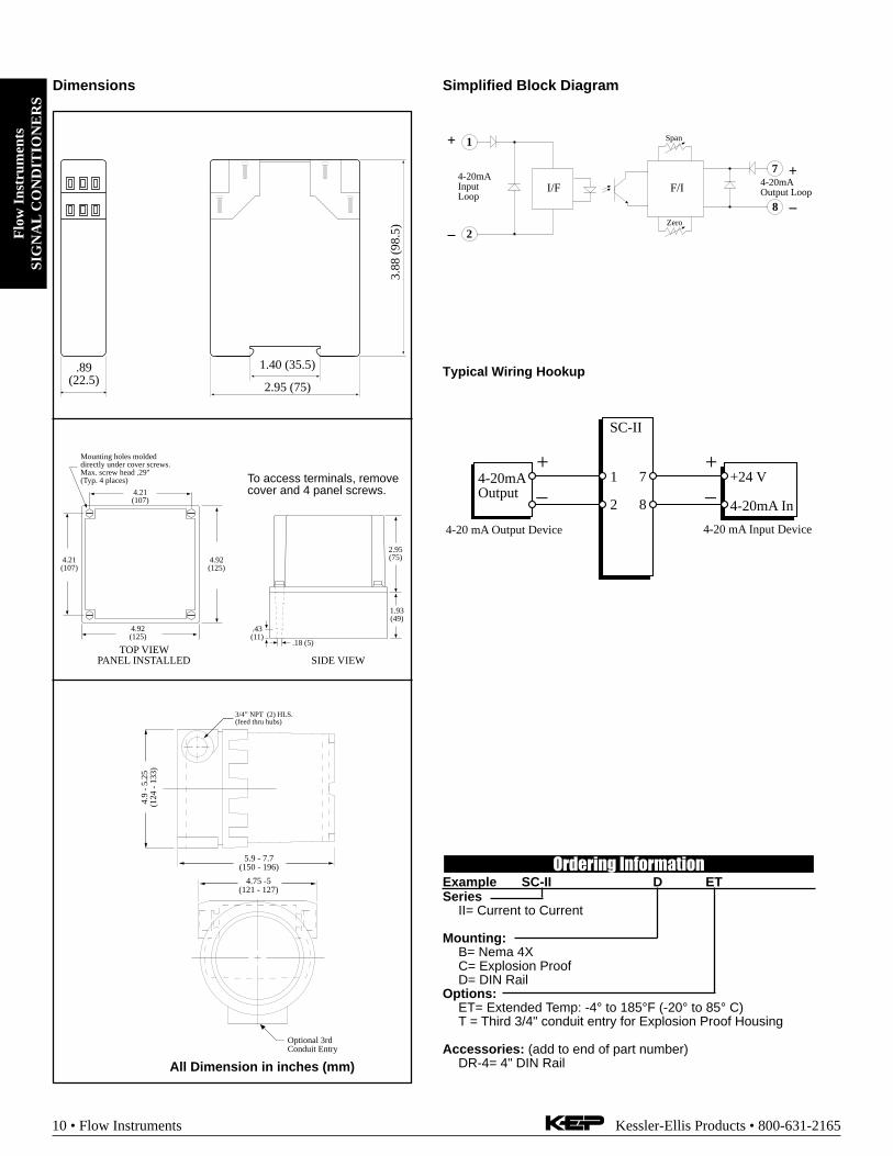
Simplified Block DiagramDimensions
+
–
I/F F/I
Span
Zero
4-20mAOutput Loop
+
–
1
2
7
8
4-20mAInputLoop
Typical Wiring Hookup
4-20mAOutput
SC-II
1 7
2 8
+24 V
4-20mA In
+
–
+
–4-20 mA Input Device4-20 mA Output Device
Ordering InformationExample SC-II D ETSeries
II= Current to Current
Mounting:B= Nema 4XC= Explosion ProofD= DIN Rail
Options:ET= Extended Temp: -4° to 185°F (-20° to 85° C)T = Third 3/4" conduit entry for Explosion Proof Housing
Accessories: (add to end of part number)DR-4= 4" DIN Rail
3.88
(98
.5)
2.95 (75)
1.40 (35.5).89 (22.5)
4.92(125)
4.92(125)
4.21(107)
4.21(107)
Mounting holes moldeddirectly under cover screws.Max. screw head .29" (Typ. 4 places)
TOP VIEWPANEL INSTALLED
To access terminals, remove cover and 4 panel screws.
2.95(75)
1.93(49)
.18 (5)
.43(11)
SIDE VIEW
4.75 -5(121 - 127)
4.9
- 5.
25(1
24 -
133
)
5.9 - 7.7(150 - 196)
3/4” NPT (2) HLS.(feed thru hubs)
All Dimension in inches (mm)
Optional 3rdConduit Entry

Flow
Instruments
SIGN
AL
CO
ND
ITIO
NE
RS
Kessler-Ellis Products • 800-631-2165 Flow Instruments • 11
SC-IF SERIES Current to FrequencyLoop Powered Isolator
Description:The SC-IF loop powered signal conditioner whose function is toprovide a 0 - 10kHz frequency output signal in response to a 4-20mA analog input.
The SC-IF appears to the input loop as a series shunt resistor. Asmall sense resistor is used to measure the input current. Theinput loop derives it’s power from the input current loop.
This input current signal is then scaled and converted to a 0 to10,000 Hz frequency signal by a Current to Frequency Con-verter. This frequency signal is then transmitted across an opto-isolator to the output stage.
The 10-50 mA range option is provided to enable the unit toperform range conversions as well as signal isolation.
Specifications:
Analog InputAvailable Ranges: 4-20 mA (10-50 mA optional)Input Type: Two Wire, Loop PoweredEquivalent Input Impedance: 525 Ω on 4-20 mA range
210 Ω on 10-50 mA rangeOperational Range: 3.5-33 mAOver Current Protection: 2.5 times rated spanReverse Polarity ProtectionIsolation Voltage: 500 VInput Loop Indicator: LED illuminates when loop is pow-
ered by proper polarity
Pulse Output OptionOutput Type: Open Collector TransistorLow Cutoff: 1% of full scaleRange: 0 to 10,000 HzDuty Cycle: 50/50 Duty Cycle (nominal)Maximum Off Voltage: 30 VDCMinimum On Current: 10 mAMaximum On Voltage: 1 VDCTemperature Effect: Less than 200 ppm/degree CReverse Polarity Protection
Mounting StylesDIN Rail Mount: Plastic enclosure with a snap fastener for
fitting to DIN 46 277 and DIN EN 50 022assembly rails.
NEMA 4: 4.92" x 4.92" NEMA 4 Enclosure for wallmounting.
Explosion Proof: Aluminum enclosure for:Class I, Division 1, Groups B, C & DClass II, Division I, Groups E, F & G.
Listing: CE Compliant
Features
• 4-20 mA Input (10-50 mA optional)
• 0 to 10 kHz Pulse Output
• Two Year Warranty
• Loop Powered
• Input & Output LED Indicators
• Various Mounting Styles

Flo
w I
nstr
umen
tsSI
GN
AL
CO
ND
ITIO
NE
RS
12 • Flow Instruments Kessler-Ellis Products • 800-631-2165
Simplified Block DiagramDimensions
Typical Wiring Hookup
Ordering InformationExample SC-IF D ETSeries
IF= Current to Frequency
Mounting:B= Nema 4XC= Explosion ProofD= DIN Rail
Options:ET= Extended Temp: -4° to 185°F (-20° to 85° C)T = Third 3/4" conduit entry for Explosion Proof Housing
Accessories: (add to end of part number)DR-4= 4" DIN Rail
4-20mAOutput
SC-IF
1
2
+24 V
Open Collector Output
Common
+
–
4-20 mA Output Device
7
8
9Pulse Input Device
24 VDC Out
Pulse Input
Common
3.88
(98
.5)
2.95 (75)
1.40 (35.5).89 (22.5)
4.92(125)
4.92(125)
4.21(107)
4.21(107)
Mounting holes moldeddirectly under cover screws.Max. screw head .29" (Typ. 4 places)
TOP VIEWPANEL INSTALLED
To access terminals, remove cover and 4 panel screws.
2.95(75)
1.93(49)
.18 (5)
.43(11)
SIDE VIEW
4.75 -5(121 - 127)
4.9
- 5.
25(1
24 -
133
)
5.9 - 7.7(150 - 196)
3/4” NPT (2) HLS.(feed thru hubs)
All Dimension in inches (mm)
Optional 3rdConduit Entry
+
–
I/F
Span
Zero
Open Collector
1
2
7
84-20mAInputLoop
9
+ 24 VDC
Common

Flow
Instruments
SIGN
AL
CO
ND
ITIO
NE
RS
Kessler-Ellis Products • 800-631-2165 Flow Instruments • 13
Features:• Pulse Scaler with Isolation
• Pulse, Contact Closure or Magnetic PickupInputs
• Two Year Warranty
• Various Mounting Styles
• Output LED Indicator
SC-FF Series Frequency to FrequencyPulse Isolator and Scaler
Description:The model SC-FF is a signal conditioner which permits the userto condition and scale the input pulses from a pulse producingsensor into a high level output where each pulse represents anengineering unit of measure.
Several pulse input types are supported including magneticpickup, contact closure, and an isolated pulse input.
The pulse scaling permits a user to apply a scaling multiplier witha value of .0001 to .9999 with additional multipliers of 1, .1, .01,.001 and .0001. Pulse scaling is accomplished by rotary en-coded and dip switch selections.
The pulse output is available in isolated, non-isolated and relayversions. User selections include output pulse duration and in-ternal pullup resistors. The user may select his pulse outputconfiguration by means of a dip switch.
The unit is powered to 8 - 35 VDC. Reverse polarity protection isprovided. Power and Pulse input/output indicators are provided.
The unit is available in enclosures intended for either DIN rail,NEMA4X or Explosion Proof.
Specifications:Pulse Input:Isolated Pulse:
Logic 1 (high): 3 - 30 VDCLogic 0 (low): 0-0.4 VDCInput Frequency Range: 0-10000 HzInput Impedance: 3.3 kΩReverse Polarity ProtectionIsolation Voltage: 500 V
Contact Closure:Switch Debounce: 40 CPS maximum count rate10000 ohm internal pullup to 5 VDC
Magnetic Pickup:Sensitivity: 30 mV p-pBandwidth: 0-3500 HzOver Voltage Protection to 30 VDC10 Kohm input resistance
Pulse Output:Pulse Duration: 50 uSec, 500 uSec 50 mSec (Switch selectable)Open Collector Pulse:
Maximum Voltage: 48 VDCMaximum Current: 100 mA @ .7V maxMax. Output Speed: 10 kHzReverse Polarity ProtectionOvercurrent ProtectionJumper selectable for 5 V and 24 V pulse output
Isolated Pulse:Maximum Voltage: 30 VDCMaximum Current: 10 mAMax. Output Speed: 1 kHzIsolation Voltage: 500 VDCReverse Polarity Protected
Output Relay (optional):Contact Rating: 0.5 amps 240 VACOutput Form: Form A (SPST)Max. Output Speed: 10 Khz
Power Input:Input Voltage Range: 8.5 to 35 VDCSupply Current: 25 mA (nominal)Reverse Polarity ProtectionTransient Protection
Pulse Scaling:Scaler: 0.0001 to .9999Multiplier: X1, X0.1, X0.01, X0.001, X0.0001
Mounting StylesDIN Rail Mount: Plastic enclosure with a snap fastener for
fitting to DIN 46 277 and DIN EN 50 022assembly rails.
NEMA 4X: 4.92" x 4.92" NEMA 4X Enclosure for wallmounting.
Explosion Proof: Aluminum enclosure for:Class I, Division 1, Groups B, C & DClass II, Division I, Groups E, F & G.
Listing: CE Compliant

Flo
w I
nstr
umen
tsSI
GN
AL
CO
ND
ITIO
NE
RS
14 • Flow Instruments Kessler-Ellis Products • 800-631-2165
Dimensions Simplified Block Diagram
Wiring:
12
3
45
6
78
9
10
1112
Magnetic pickup
Magnetic pickup
Contact Closure Input
Common
Opto-isolator In (+)
Opto-isolator In (-)
(+) DC Power Input
DC Power Input Common
Pulse Output (+)
Common
Isolated Pulse Out (+) / Relay Output
Isolated Pulse Out(-) / Relay Output
Pulse RateMultiplier
.0000 to .9999
+–
mVInput
3-30VInput
3.3kΩ
10kΩ
10kΩ
LPF
ThumbwheelSwitch
Pulse RateDivider
1, 10, 100,1000,10000
DividerSelectSwitch
ContactClosure
50 µsec 50 msec
Duration Select
5 VRegulator
Isolated PulseOutput
RelayOutput
(optional)
PulseOutput
DCInput
1
2
5
6
3
4
7
8
9
10
11
12
11
12
Pulse OutputLED Indicator
500 µsec
Pulse DurationMonostable
+5V
+
–
+
–
+
–
+
–
Ordering InformationExample SC-FF 1 B ETSeries
FF= Frequency to FrequencyOutput Type
1 = Open Collector & Isolated Pulse (STD)2 = Open Collector & Relay Output
Mounting:B= Nema 4XC= Explosion ProofD= DIN Rail
Options:ET= Extended Temp: -4° to 185°F (-20° to 85° C)T = Third 3/4" conduit entry for Explosion Proof Housing
Accessories: (add to end of part number)DR-4= 4" DIN Rail
Typical Application:
Raw Signal
Flowmeterwith Magnetic Pickup
SC-FFMag Pickup Input
12
79
108
+
–
ScaledPulseOutput
3.88
(98
.5)
2.95 (75)
1.40 (35.5).89 (22.5)
4.92(125)
4.92(125)
4.21(107)
4.21(107)
Mounting holes moldeddirectly under cover screws.Max. screw head .29" (Typ. 4 places)
TOP VIEWPANEL INSTALLED
To access terminals, remove cover and 4 panel screws.
2.95(75)
1.93(49)
.18 (5)
.43(11)
SIDE VIEW
4.75 -5(121 - 127)
4.9
- 5.
25(1
24 -
133
)
5.9 - 7.7(150 - 196)
3/4” NPT (2) HLS.(feed thru hubs)
All Dimension in inches (mm)
Optional 3rdConduit Entry

Flow
Instruments
PRO
CE
SS & L
EV
EL
MO
NIT
OR
S
Kessler-Ellis Products • 800-631-2165 Flow Instruments • 15
Process, Level, Temperature Monitors Tutorial
STOP
STARTPRINT
5
0 –
TIME
CLEAR
•
MENU
ENTERHELP
TEMP4
PRE 13
LEVEL2
TOTAL1
GRAND6
SCROLL7
PRE 28
DENS9
T
UltrasonicLevel Sensor
Temperature Transmitter
TemperatureTransmitter
4-20 mA Output
Alarm A
Alarm B
4-20 mA Out toStrip Chart Recorder
RS232 toComputer
INT69-PM2
What is a Process Indicator? This is a general purpose instrument that is intended to condition the electrical signalgenerated by a process sensor and scale the resulting flow information into a display in the units of measure desired by the enduser. Additional, functionality such as alarms, analog output, and serial communications may also be provided. See the figurebelow for a typical system configuration.
What capabilities should I look for to assure compatibility with my type of sensor? Indicators are available to workwith most process sensor types and most common electrical signals produced by these sensors. Some are termed “universal” andoperate with many sensor types. Begin by selecting an instrument(s) that will work with the signal provided by the type of sensoryou are considering. In some cases an amplifier or signal conditioner may be necessary. Next, decide on whether linearization orother forms of compensation will be required within the Indicator and on how the calibration will be represented within the instru-ment. Also determine if the Process Indicator can provide the power required for the sensor (if needed).
What are some basic areas of concern? Most customers begin selecting an indicator by looking for an instrument thatwill display the type of information that they prefer. It must work with the available power and must be available in a package thatcan be mounted in the desired location.
What is an analog output and why is it used? Process information is usually sent from one system to another as a 4-20mA. Some instruments permit the user to select what item of information is to be sent on the analog output. The correspondingspan is user programmable. Additional features may include programmable damping.
What is an alarm output and why is it used? Relays are often used as controls to activate alarms. An alarm will usuallyinclude a provision for setting the alarm point. Additional features may include a programmable delay before the alarm will activate,programmable alarm duration, and/or a programmable alarm hysteresis.
What are remote inputs and how are they used? Often there is a need to connect a remote switch near the operator forsuch purposes as remote alarm reset, or remote print. Some process indicators offer a variety of capabilities as remote inputs.
What is serial communications and why is it used? Serial communications is used to transmit information betweentwo computers, or between a computer and a printer. There are several commonly used standard hardware interfaces. Theseinclude RS-232 RS-422 and RS-485. There are also a variety of communication protocols, or message formats, which are used.Some of these protocols are unique to an equipment manufacturer while others are industry standards. See also "CommunicationSolutions" section.
What are other areas of concern? Many areas where process indicators are installed are out of doors or are in hazard-ous areas. Special purpose enclosures are available for many instruments subject to these harsh conditions.
Typical Applications
Process IndicatorApplication Level Monitor Application

Flo
w I
nstr
umen
tsPR
OC
ESS
& L
EV
EL
MO
NIT
OR
S
16 • Flow Instruments Kessler-Ellis Products • 800-631-2165
Temperature/Process MonitorWith or Without AlarmsTP-550 Series
Features• Very bright LED display, height 14mm
• DIN housing, 96 x 48 mm
• Programmable operating curve for standardsignals, thermocouples,resistance thermom-eters, etc.
• Programmable operating curve, even non-linear, allowing the use of economical sensors
• Two relay outputs with two preset limit values
Additional features:• DIN housing 96 x 48 mm• Character height: 14 mm• Resolution 14 bits• Simple menu-driven programming, and operation
with 4 keys• Electrical connections by means of plug-in screw
terminals• Voltage supply: 10-30 VDC or 90-260 VAC• IP 65/NEMA4 (front)• Auxiliary power supply output for transducer or
sensor10..30 VDC: 10 VDC ± 2%, 30 mA90..260 VAC: 24 VDC ± 15%, 50 mA and 10 VDC± 2%, 30 mA
• Hum eliminator (50/60 Hz user selectable)• Coming Soon: Serial interface allows reading of
the measured values and set-up programming.
Order CodeExample: TP554.010 0 00Series:
TP551.012 = No Presets/RelaysTP554.010 = 2 Presets/Relays
Operating Voltage:0 = 90 to 260 VAC3 = 10 to 30 VDC
Options:00= None
3.78 (96)
1.89
(48
)
2.64 (67.1)
0.26 (6.5)0.16 (4)0.61
(15.5)
1.77
x 3
.62
(44.
9 x
91.9
)
1.77
(45
)
3.62 (92) Dimensions are in inches (mm)
Dimensions
TP554 Specifications:Process controller for thermocouples, resistancethermometers and sensors with mV range; twopreset limit values• Display range: -19.999..99.999• Input ranges:
0..400 Ω, 0..4000 Ω0..100 mV, -100..+100 mV
Thermocouples• Integrated operating curves for
thermocouples(types B, C, D, E, G, J, K, L, N, R,S, T, U)
• Programmable input operating curve with up to 24reference points
• 2 programmable limit values (TP551; unit withoutpresets, has only 2 buttons)
• Outputs: Two (2) SPDT relays (250 VAC / 3A)• Programmable hysteresis (on, off, on/off)• SET key to reset the outputs• Inputs: thermocouple, millivolt, resistance ther-
mometer with measurement on 2, 3 or 4 wires,RESET to reset the outputs, KEY terminal to lockthe front keys.

Flow
Instruments
PRO
CE
SS & L
EV
EL
MO
NIT
OR
S
Kessler-Ellis Products • 800-631-2165 Flow Instruments • 17
Electrical Connections
1 Measuring input 1 (Sense)
2 Measuring input 2 (– Ref)
3 Sensor (+Ref)
4 Current output for 0 .. 4000 Ω (+ Sense)
5 Current output for 0 .. 400 Ω (+ Sense)
TB1
6 Keys locking
7 Reference ground Reset / Key
8 Reset
9 GND for DC Output (Pins 10 & 11)
10 +10 VDC Out (30 mA)
11 +24 VDC Out (50 mA) (AC units only)
NOTE: Check unit label before applyingpower
1 Output 1 Relay C Optocoupler Emitter
2 Output 1 Relay N.O.
3 Output 1 Relay N.C. Optocoupler Collector
4 Output 2 Relay C Optocoupler Emitter
5 Output 2 Relay N.O.
TB2
6 Output 2 Relay N.C. Optocoupler Collector
7 Power In AC 90 to 260V DC 10 to 30V
8 Power In AC 90 to 260V DC 0V (GND)
Power Supply
Thermocouples
Negative leg of thermocouple
Positive leg of thermocouple
Resistance measurements 0 .. 400/4000 ΩΩΩΩΩ orPt 100/1000
2 wire measurement (measuring resistance 0 .. 400/4000 Ω)NOTE: Not recommended for long runs.
Mea
surin
g in
put 1
(S
ense
) •
1M
easu
ring
inpu
t 2 (
– R
ef)
• 2
Sen
sor
(+
Ref
) •
3C
urre
nt o
utpu
t for
0 ..
400
0 Ω
(+
Sen
se)
• 4
Cur
rent
out
put f
or 0
.. 4
00 Ω
(+ S
ense
) •
5K
eys
lock
ing
• 6
Ref
eren
ce g
roun
d R
eset
/ K
ey •
7R
eset
• 8
GN
D fo
r D
C O
utpu
t (P
ins
10 &
11)
• 9
+10
VD
C O
ut (
30 m
A)
• 10
+24
VD
C O
ut (
50 m
A)
(AC
uni
ts o
nly)
• 1
1
1 2 3 4 5 6 7 8 9 1011
Measuring input 1 (Sense) • 1Measuring input 2 (– Ref) • 2
Sensor (+Ref) • 3Current out for 0 - 4000 Ω/Pt 1000 (+ Sense) • 4
Current out for 0 - 400 Ω/Pt 100 (+ Sense) • 5Keys locking • 6
Reference ground Reset / Key • 7Reset • 8
GND for DC Output (Pins 10 & 11) • 9+10 VDC Out (30 mA) • 10
+24 VDC Out (50 mA) (AC units only) • 11
12
34
56
78
910
11
Rϑ
3 wire measurement (measuring resistance 0 .. 400/4000 Ω)NOTE: Jumper 1 & 2 at meter, wires 3 & 4 must go to sensor
Voltage measurement (0 to 100mV or -100 to +100mV)
4 wire measurement (measuring resistance 0 .. 400/4000 Ω)NOTE: All 4 wires must go to sensor
1 2 3 4 5 6 7 8 91011
1 2 3 4 5 6 7 8
TB1
TB2
NOTE: For accurate readings,use only leads of sametype thermocouple wirewithout junctions to dis-similar metals.
TB1
TB1
TB1
Measuring input 1 (Sense) • 1Measuring input 2 (– Ref) • 2
Sensor (+Ref) • 3Current out for 0 - 4000 Ω/Pt 1000 (+ Sense) • 4
Current out for 0 - 400 Ω/Pt 100 (+ Sense) • 5Keys locking • 6
Reference ground Reset / Key • 7Reset • 8
GND for DC Output (Pins 10 & 11) • 9+10 VDC Out (30 mA) • 10
+24 VDC Out (50 mA) (AC units only) • 11
12
34
56
78
910
11
Rϑ
TB1
+/– Measuring input
Reference ground
Mea
surin
g in
put 1
(S
ense
) •
1M
easu
ring
inpu
t 2 (
– R
ef)
• 2
Sen
sor
(+
Ref
) •
3C
urre
nt o
utpu
t for
0 ..
400
0 Ω
(+
Sen
se)
• 4
Cur
rent
out
put f
or 0
.. 4
00 Ω
(+ S
ense
) •
5K
eys
lock
ing
• 6
Ref
eren
ce g
roun
d R
eset
/ K
ey •
7R
eset
• 8
GN
D fo
r D
C O
utpu
t (P
ins
10 &
11)
• 9
+10
VD
C O
ut (
30 m
A)
• 10
+24
VD
C O
ut (
50 m
A)
(AC
uni
ts o
nly)
• 1
1
1 2 3 4 5 6 7 8 9 1011
+ –
TB1

Flo
w I
nstr
umen
tsPR
OC
ESS
& L
EV
EL
MO
NIT
OR
S
18 • Flow Instruments Kessler-Ellis Products • 800-631-2165
Features• Analog Input 0-20 mA, 4-20 mA
0-5V, 0-10V or 1-5V
• Display Rate, Pressure, Level, Temperature,Watts, etc., Peak & Valley
• Calibration, High and Low Values (-9999 to49999) Fully Programmable Through Keypad
• NEMA 4X / IP65 Front
• +24V Output for Peripherals
• 16 Bit A/D Resolution
• 2 Form C SPDT Relays (optional)
• 2 Levels of Operator Password Lockout
Process Monitorwith Analog InputsIntellect-69PM2
Application:Any process monitoring application where two set pointsand scaling are needed.
Description:Featuring 41/2 digits of bright, 7-segment LED displays, theIntellect-69PM2 is a process monitor which accepts ana-log signal inputs. The unit can be field programmed toaccept 0-20mA, 4-20mA, 0-5V, 0-10V or 1-5V signals.Two assignable set points are standard for high/low alarmoutputs. The high and low scaling settings (-9999 to49999) are programmable from the front panel. By press-ing the "view" button, the unit will display: process status,peak or valley. Press the lock button once to freeze thedisplay, press it again to resume normal operation. Pressthe lock button 4 times to enter lock code for panel lock-out. RS-232, RS-422 and 4-20mA analog out are avail-able options for interfacing to a host computer or stripchart recorder.
Specifications:Display:41/2 digit, .55" high, 7 segment, red orange, LED.Input Power: 110, 220 VAC ± 15% or 12 to 24VDC.Current: 300 max. mA DC or 10.0 VA at rated AC voltage.Output Power:(AC powered units only) + 24VDC @ 50mA regulated±5%.Temperature:Operating: +32°F (0°C) to +130°F (+54°C).Storage: -40°F (-40°C) to +200°F (93°C).Memory: EEPROM stores data for ten years if power islost.
Reset:Front Panel: resets displayed value and control outputs.Control Outputs:Standard: Open collector sinks 250mA from 30VDC whenactive.Optional: 2 each Form C SPDT 5 Amp @ 120/240 VAC or28 VDC.Input: Linear 0-20mA, 4-20mA, 0-5V, 0-10V or 1-5V se-lectable from the front panel.Calibration: The unit does all of the calibrations inter-nally. There are no potentiometers to adjust and the unitnever needs to be removed from the case.Set Points: Two control set points are provided. The unitcomes standard with two open collector control outputs.Two 5 Amp, Form C relays are optional. The outputs havea programmable hysteresis alarm range from 0 to 59999.Process Display: Updates 4 times per second, Accurateto 4.5 digits.Programming: Decimal points, Scaling from -9999 to49999, set points, input type and security lock code are allprogrammable from the front panel.Housing: Standard 1/8 DIN, high impact ABS plastic case(NEMA 4X/IP65 front panel).Shipping Weight: 2 lbs.Overvoltage Protection: 50 VOver-current Protection: 50 mATemperature Stability: Will not drift more than 10 partsper million per °C from 0°C to 54°CAccuracy: .1% (5 V inputs .16%)Listing: CE Compliant, CSA (File No. LR91109),
NRTL/C pending

Flow
Instruments
PRO
CE
SS & L
EV
EL
MO
NIT
OR
S
Kessler-Ellis Products • 800-631-2165 Flow Instruments • 19
DIMENSIONS:
4.44(112.7)
2.63
(66.
8)
3.93(99.8)
3.62(92)
1.77
(45)
0.6(15)
4.35(110.5)
GASKET
CUSTOMER PANELPanel Thickness 0.062" (1.5)to 0.187" (4.7) max.
Typical Hookups:
Wiring:
Ordering InformationEXAMPLE: INT69PM2 A 1 ASeries
INT69PM2= Process MonitorOperating Voltage
A= 110 VAC ± 15% or 12 to 24 VDCB= 220 VAC ± 15% or 12 to 24 VDC
Control outputs1= 2 - Open Collector Outputs2= 2 - 5 Amp Form C Relays
Options (multiple options available)A= Analog Output (4-20mA)C1= RS232 CommunicationsC2= RS422 CommunicationsCSA: CSA Approved Unit
AccessoriesSeparate non keyboard panel order #34235Separate keyboard panel - order #34234XHV Explosion Proof Housing (see Accessories)NEMA-1/8DIN NEMA 4 wall mount enclosure (see Accessories)
Flowmeter(4-20mA Transmitter)
110 VAC60/50 Hz•2
- A
nalo
g O
ut•3
- S
igna
l GN
D (
-DC
)•4
- I
In
+ (
Cur
rent
). •7
- +
24V
Out
. •11
- AC
In
•12
- AC
In
+-
-
Strip ChartRecorder
+
•13 Common•14 N.C.•15 N.O.•16 Common•17 N.C.•18 N.O.
Relay A
Relay B
AC Supply
MOVrecommendedfor inductive
loads
Neutral
LOAD
- +DCSupply
LOAD-
+ Dioderecommendedfor inductive
loads
2-Wire 4-20mA Transmitter with Analog Output
Relay Output
2-Wire 4-20mA Transmitter
Temperature/Pressure(4-20mA Transmitter)
110 VAC60/50 Hz
•3 -
Sig
nal G
ND
(-D
C)
•4 -
I I
n +
(C
urre
nt)
. •7 -
+24
V
Out
. •1
1 -
A
C I
n•1
2 -
A
C I
n
-
+
3-Wire 0-10V Transmitter
Flowmeter(0-10 V Transmitter)
110 VAC60/50 Hz
•3 -
Sign
al G
ND
(-D
C)
. •5 -
V
In +
(Vol
tage
). •7
- +2
4V O
ut. •1
1 - A
C In
•12
- A
C In
-
+signal
1•R
ese
t In
2•A
na
log
Ou
t (S
ink)
3•S
ign
al G
RD
(-D
C)
4•(
Cu
rre
nt)
+I
in5
•(V
olta
ge
) +
V in
6•N
ot
Use
d7
•+2
4V
Ou
t8
•Pre
set
B C
olle
cto
r9
•Pre
set A
Co
llect
or
10
•+D
C I
n11
•11
0/2
20
VA
C1
2•1
10
/22
0 V
AC
13
•Co
mm
on
14
•N.C
.1
5•N
.O.
16
•Co
mm
on
17
•N.C
.1
8•N
.O.
Re
lay
A
Re
lay
B

Flo
w I
nstr
umen
tsPR
OC
ESS
& L
EV
EL
MO
NIT
OR
S
20 • Flow Instruments Kessler-Ellis Products • 800-631-2165
Features• Linear or Square Root Extraction of Input
• 3 1/2 or 4 1/2 Digit Display (Selectable)
• Calibration, High and Low Values FullyProgrammable Through Keypad
• NEMA 4X / IP65 Front
• No Dipswitches or Pots to Adjust
• 16 Bit A/D Resolution
• Password Protection of Menu
Loop Powered IndicatorSquirt-R
Description:Featuring up to 4 1/2 digits of display, the Squirt-R is aloop powered indicator capable of accepting either linearor square root 4-20 mA inputs. Numeric password protec-tion prevents unauthorized access to the menu. The easy-to-read menu prompts make the Squirt-R so easy to pro-gram that you will feel comfortable programming it withoutthe use of a manual.
Specifications:Power:Loop powered 4-20 mAInternal Battery (Setup memory storage only):3 V 250 mA-H Lithium (2 yr. Standby life)Display:Display: (selectable decimal)
3.5 or 4.5 Digits (selectable), 0.35" High, Display up-dates once every two seconds.Rate Descriptors: /SEC, /MIN, /HR or "blank"
Units Descriptors: GAL, LIT, FT3, M3, "blank"Low Battery Error Detection: "BAT" descriptor & flashing
displayUnder/Over range Indication: Display flashes when out of
rangeEnvironmental:OPERATING TEMPERATURE
-4°F (-20°C) to + 158°F (70°C)Extended Temp: -22°F (-30°C) to + 158°F (70°C)
HUMIDITY0 - 90% Noncondensing
Listing: CE Compliant
Accuracy: (Rate @ 20°C)0.1% Full Scale ResolutionTemperature Drift:
50 ppm/°C Typical200 ppm/°C Worst Case
Lockout:Password: Unauthorized menu changes can be pre-
vented by entering a user selectable password (5 digitnumber).
Jumper: An internal jumper shunt is provided for a"sealed" menu lockout. Install the jumper to enable thelock.
Inputs:Signal Input:
Full Scale Range: 4 to 20 mA DCLoop Voltage Drop: 6 Volts MaximumReverse Polarity ProtectedOver Current Protection to 60 mA16 Bit resolution; 1 sample every 2 secondsLow Cutoff supplied to inhibit indications at low flowrates.
Calibration & Operation:Input Scaling: Via front keypadCalibration: Via front keypadDecimal Point: Via front keypadKeypad: 4 tactile feedback keysMounting Styles:0- Circuit Board - OEM option (consult factory)1- Panel Mount - NEMA 4X Clear Front2- Wall Mount - NEMA 4X Enclosure (unit mounted
behind clear cover)3- Explosion Proof - Class I, Division I, Groups B, C & D
Class II, Division I, Groups E, F & G5- Wall Mount - NEMA 4X with keypad mounted
outside opaque cover

Flow
Instruments
PRO
CE
SS & L
EV
EL
MO
NIT
OR
S
Kessler-Ellis Products • 800-631-2165 Flow Instruments • 21
Typical Wiring: (2-Wire Transmitter)
Do Not Use 6Do Not Use 5Do Not Use 4Do Not Use 3Input + (+I) 2Input - (-I) 1
+
Flowmeter(4-20mA Transmitter)
Rear View
Jump momentarily to initializeunit prior to calibration. Useonly after battery replacement.Loop power must be appliedwhen initializing.
1 2
3 4
5 6
-
Install jumperto enablefront panellockout.
DataAcquisitionorDC PowerSupply24V Typ.
+
-
4.95(125.7)
4.95 (125.7)
4.33
(110
)
4.33(110)
Mounting holes molded directly under coverscrews. Max. screw head .29" (Typ. 4 places)
TOP VIEW
E M 3.0(76.2)
0.18 (5)
0.43(11)
SIDE VIEW
To access terminals, remove coverand 4 panel screws. Terminals areon bottom side of PC board.
Panel Screws (4 places)
E M
3.0120 DIAMETER
.900(22.8)
.992(25.2)
Mounting holes.125 Drill (2 places).438 Nylon SpacerSupplied
1.20(30.5)
2.875(73)
.10(2.5)
.438(11.1)
.900(22.8)
.992(25.2)
.10(2.54)
3.062" (77.77)Dia. Cutout
Fem
ale
Plu
g-In
Con
nect
or
4.00(101.6)
3.582" Dia. Bolt Circle.125" Holes to be 120° Apart
Outside Dotted Line ShowsOutside Panel Dimension(4.00" Diameter)
120°
PanelCutout
1.20(30.5)
2.875(73)
SquirtR-1SquirtR-0
SquirtR-3SquirtR-2
.75(19)
1.44(36.6)
4.50(114.3)
2.50(63.5)3.44
(87.4)
4.31(109.5)
1/2 NPT (2) HLS.(feed thru hubs)
E M
4.50(114.3)
1.95(49.53)
3.25(82.55)
2 MTG LUGS.31 DIA. HOLES
PanelScrews(2 Places)
To access terminals, unscrew cover and loosen 2 panel screws. Terminals are on bottom side of PC board.
SquirtR-5
5.125(130.2)
5.125 (130.2)
4.47
(113
.5)
4.47(113.5)
Mounting holes molded directly under coverscrews. Max. screw head .29" (Typ. 4 places)
TOP VIEW
E M 3.125(79.4)
0.18 (5)
0.43(11)
SIDE VIEW
To access terminals, remove coverand 4 panel screws. Terminals areon bottom side of PC board.
Ordering InformationExample: SQUIRTR 3 ETSQUIRTR
Loop powered; Rate OnlyMounting:
0 = OEM1 = Panel Mount2 = NEMA 4X Box (Squirt behind clear cover)3 = Explosion Proof Housing5 = NEMA 4X Box (Squirt outside opaque cover)
Options:ET = Extended Temp.: -22°F to 158°F (-30°C to 70°C)H2 = 0.875" Hole for mounting styles 2 and 5HF2 = 0.5" Female NPT Hub fittingH3 = 1.125" Hole for mounting styles 2 and 5HF3 = 0.75" Female NPT Hub fitting

Flo
w I
nstr
umen
tsPR
OC
ESS
& L
EV
EL
MO
NIT
OR
S
22 • Flow Instruments Kessler-Ellis Products • 800-631-2165
Features
• Level and Tank Volume Indicator
• Batching by Level
• Level Control, Tank Volume,Corrected Volume and Mass Calculations
• Menu Selectable Hardware & Software Features
• Two Line LCD or VFD Display
• Isolated Outputs Standard
• RS-232 Port Standard, RS-485 Optional
• DIN Enclosure with Two Piece Connectors
• DDE Server & HMI Software Available
• NEW! - Attractive Wall Mount Enclosure
Multi-Function Level Indicator, Controller and BatcherLEVELtrol II
Description:The LEVELtrol II Flow Computer satisfies the instrumentrequirements for a variety of level sensor types in liquidapplications. Multiple tank geometries, fluid equations andinstrument functions are available in a single unit with manyadvanced features.
The alphanumeric display shows measured and calculatedparameters in easy to understand format. Single key directaccess to measurements and display scrolling are supported
The versatility of the LEVELtrol II permits a wide measure ofversatility within the instrument package. The various hardwareinputs and outputs can be “soft” assigned to meet a variety ofcommon application needs. The user “soft selects” the usage ofeach input/output while configuring the instrument. Consider thefollowing illustrative examples.
The isolated analog output can be chosen to follow level, tankvolume, corrected tank volume, tank mass, temperature, or densityby means of a menu selection. Most hardware features areassignable by this method.
The user can assign the standard RS-232 Serial Port for datalogging, transaction printing, or for connection to a modem forremote meter reading.
Specifications:Environmental
Operating Temperature: 0°C to +50°CStorage Temperature: -40°C to +85 CHumidity : 0-95% Non-condensingMaterials: U.L. approved
Listing: UL/C-UL Listed (File No. E192404), CE Compliant
DisplayType: 2 lines of 20 charactersTypes: Backlit LCD and VFD ordering optionsCharacter Size: 0.3" nominalUser programmable label descriptors and units of measure
Trend, Alarm and Log
your LEVELtrol II Data with
KEPware HMI Software!
See Special Flow Instruments Section
KeypadKeypad Type: Membrane KeypadNumber of keys: 16
EnclosureStyle: See Ordering Code for Available Mounting OptionsSize: See DimensionsDepth behind panel: 6.5" including mating connectorType: DINMaterials: Plastic, UL94V-0, Flame retardantBezel: Textured per matt finish
Power InputThe factory equipped power option is internally fused. Aninternal line to line filter capacitor and MOV are provided foradded transient suppression.110 VAC Power Option: 85 to 127 Vrms, 50/60 Hz220 VAC Power Option: 170 to 276 Vrms, 50/60 HzDC Power Option:
12 VDC (10 to 14 VDC)24 VDC (14 to 28 VDC)
Power CosumptionAC Power: 11.0 V/ADC Power: 300 mA max.
Level Inputs:Analog Input:Accuracy: 0.01% FS at 20° C
RangesVoltage: 0-10 VDC, 0-5 VDC, 1-5 VDCCurrent: 4-20 mA, 0-20 mA
Basic Measurement Resolution: 16 bitUpdate Rate: 4 updates/secAutomatic Fault detection: Signal over/under-range,
Current Loop BrokenCalibration: Software Calibration (no trimmers) and Auto-
zero ContinuouslyExtended calibration:
Learns Zero and Full Scale of each range using specialtest mode.
Sensor Types Supported:Differential PressureUltrasonicMany Others

Flow
Instruments
PRO
CE
SS & L
EV
EL
MO
NIT
OR
S
Kessler-Ellis Products • 800-631-2165 Flow Instruments • 23
Tank Geometries:Horizontal, vertical, spherical and 32 point strapping table
Auxiliary / Compensation InputThe auxiliary/compensation input is menu selectable fortemperature, density or not used. This input is used for thecompensated input when performing compensated tank volumeand mass calculations. It can also be used as a general purposeinput for display and alarming.Available Input Ranges
Voltage: 0-10 VDC, 0-5 VDC, 1-5 VDCCurrent: 4-20 mA, 0-20 mAResistance: 100 Ohms DIN RTD
Control InputsSwitch Inputs are menu selectable for Start, Stop, Reset, Lock,Alarm Acknowledge, Print or Not Used.
Relay OutputsThe relay outputs are menu assignable to Level, Tank Volume,Temperature, Density, Batch Control or MalfunctionNumber of relays: 2 (4 optional)Contact Ratings: 5 amp, 240 VAC or 30 VDC
Isolated Analog OutputThe analog output is menu assignable to correspond to the Level,Tank Volume/Mass, Temperature or Density.Type: Isolated 4-20 mA Current Sourcing
Excitation Voltage24 VDC @ 100 mA (fault protected)
Terminal Designations:Wall Mount Dimensions:
Standard Dimensions:
13P
ULS
E O
UT
PU
T +
PU
LSE
OU
TP
UT
-
AN
ALO
G O
UT
PU
T -
AN
ALO
G O
UT
PU
T +
RLY
1
RLY
2
AC
LIN
EA
C L
INE
2418C
OM
19 20 21 22 23
NO
NC
CO
MN
O
14 15 16 17N
C
PO
WE
R IN
DC
-
4-20
mA
CO
M R
LY3
CO
M R
LY4
26 27 28 29 30
NO
NC
NO
DC
+25N
C
DC
OU
TP
UT
CO
MM
ON
RT
D E
XC
IT +
RT
D S
EN
SR
TD
SE
NS
-
CN
TR
IN 1
CN
TR
IN 2
CN
TR
IN 3
CO
MM
ON
----
----
-
8 9 10 11 122 3 4 5 6 71
SE
E U
SE
RM
AN
UA
L
CO
MP
Iin +
+
Vin
+Iin
+
Vin
+
IN IN
LEV
EL
Isolated Pulse outputThe isolated pulse output is menu assignable to generate pulseoutputs when tank fills, empties or both.Pulse Output Form: Isolated Open CollectorMaximum On Current: 25 mAMaximum Off Voltage: 30 VDCPulse Duration: 10 msec or 100 msec
Serial CommunicationThe serial port can be used for printing, datalogging, modemconnection and communication with a computer.RS-232:
Device ID: 01-99Baud Rates: 300, 600, 1200, 2400, 4800, 9600, 19200Parity: None, Odd, EvenHandshaking: None, Software, HardwarePrint Setup: Configurable print list and formatting
RS-485:Device ID: 01-247Baud Rates: 300, 600, 1200, 2400, 4800, 9600, 19200Parity: None, Odd, EvenProtocol: Modbus RTU (Half Duplex)
Real Time ClockLEVELtrol II is equipped with a battery backed real time clock withdisplay of time and date.Format:
12 or 24 hour time displayDay, Month, Year date display
Ordering InformationExample LT2 L 1 B 0 PSeries:
LT2 = LEVELtrol IIDisplay Type:
L= LCDV= VFD
Input Type:1= 110 VAC2= 220 VAC3= 12 VDC (10 to 14 VDC)4= 24 VDC (14 to 28 VDC)
Relays:A= 2 SPDT RelaysB= 4 SPDT Relays
Network Card:0= None (STD)2= RS485/Modbus (available soon)
Mounting:P= Panel MountN= NEMA 4 Wall MountW= NEMA 12/13 Wall Mount w/ Clear CoverE= Explosion Proof (No Button Access)X= Explosion Proof (with Button Access)
OptionsCSA: CSA Approved Unit (pending) .................. (consult factory)
Accessories:KEPS-KEP1-32 = KEP RS232 for SUPERtrol 1, SUPERtrol 1LE, SUPERtrol 2and LEVELtrol 2 • 32 Bit DDE ServerP1000 Printer (see Accessories)IM-2400 = Internal Modem for SUPERtrol FamilyMPP2400 = Port Powered ModemMPP2400N = Port Powered Modem in NEMA4X Enclosure
7.64 (194)
6.34
(16
1)
2.15
(54.
5)
2.32(59)
0.4(10) 1.06
(27)1.10(28)
1.16(29.5)
0.75(19)
1.10(28)
1.10(28)
5.95 (151)
0.63(16)
0.55(14)
1.14(29)
4.72
(12
0)
MENU
ENTER
TOTAL RATE
1 2
6 7
GRAND SCROLL
ALARM 1 TEMP
3 4
8 9
PRESALARM 2
PRINTCLEAR
5
0 - .
TIME HELP
4.8 (122)
0.75” Conduit Knockouts(3 places)
5.67 (144)
2.83(72)
6.15 (156) 0.5(13)
0.28 (7.2)
3.43(87)
6.18 (157)
Dotted Line Shows Optional Bezel Kit
PanelCutout
5.43(138)
2.68(68)
Dimensions are in inches (mm)
0.4 (10)
STOP
STARTPRINT
5
0 –
TIME
CLEAR
•
MENU
ENTERHELP
TEMP4
PRE 13
RATE2
TOTAL1
GRAND6
SCROLL7
PRE 28
DENS9
RATETOTAL 267395.749
GPMGAL
147.43

Flo
w I
nstr
umen
tsF
IEL
D I
ND
ICA
TO
RS
24 • Flow Instruments Kessler-Ellis Products • 800-631-2165
Field Indicators TutorialField indicators are signal conditioner/converter devices with a display. Field Indicators are intended for mounting on or near theflow sensor. They perform many of the same roles of signal conditioner/converters plus that of providing a convenient local display.
Many “smart” Field Indicators provide additional, advanced functionality such as sensor linearization.
Field Indicators are ancillary display devices also intended to amplify, filter, condition, scale, and convert the low level “raw” signalsproduced by many transducers and convert it into the desired, industry standard high level signal before transmitting it across apotentially noisy environment. In some cases, a secondary function is providing signal isolation.
Generally, the output signals may be in the form of either a pulse and/or analog current/voltage that is proportional to the span ofthe signal being measured. Open collector transistors are common as pulse output signals. The most common analog signal is a 4-20mA current signal.
In many flowmeter types the frequency of the raw input signal carries the flow information. The frequency is related to flow rate.Each pulse or cycle is related to a small equivalent quantity of flow. The quantity represented by each pulse varies with eachindividual meter and must be scaled to obtain engineering units.
The input signal to a pulse signal conditioner may be a contact closure, a magnetic pickup, or a low level pulse. Some conditioner/converters scale the pulse signal such that each pulse represents a engineering quantity of flow, for example 1 pulse per gallon).Some converters convert the variable frequency signal into a current proportional to flow rate.
In many cases, the field indicator is intended to be powered either by an internal battery, or by the 4-20mA output current loop, orby a DC supply voltage normally available in most instruments with 24 VDC being the most common.
Enclosures are available for outdoor weatherproof and also hazardous locations. Most have provisions for mounting on theflowmeter and/or near the flowmeter.
Field Rate/Total Indicators are applied in most PLC and PC based control systems to adapt the process signals into the standard-ized levels provides on I/O Cards while at the same time providing a display of information in the field.
Typical Application
BAT R/Tmounted with
flowmeter
E M

Flow
Instruments
FIE
LD
IND
ICA
TO
RS
Kessler-Ellis Products • 800-631-2165 Flow Instruments • 25
Loop Powered IndicatorSQUIRTFeatures• Linear or Square Root Extraction of Input
• 3 1/2 or 4 1/2 Digit Rate Display (Selectable)
• 8 Digit Totalizer Display
• Calibration, High and Low Values Fully Pro-grammable Through Keypad
• No Dipswitches or Pots to Adjust
• 16 Bit A/D Resolution
• Isolated Scaled Pulse Output
• Password Protection of Menu and Totalizer
Description:Featuring up to 41/2 digits of rate and 8 digits of total, the Squirt isa loop powered indicator capable of accepting either linear orsquare root 4-20 mA inputs. An isolated scaled pulse output isavailable for hook up to a remote totalizer. Numeric passwordprotection prevents unauthorized access to menu. The easy-to-read menu prompts make the Squirt so easy to program that youwill feel comfortable programming it without the use of a manual.
Specifications:Power:Loop powered 4-20 mAInternal Battery (Setup & totalizer memory storage only):3 V 250 mA-H Lithium (2 yr. Standby life)Display:Rate Display: (selectable decimal)
3.5 or 4.5 Digits (selectable), 0.35" High, Display updatesonce every two seconds.Rate Descriptors: /SEC, /MIN, /HR or "blank"
Totalizer Display: (selectable decimal)8 Digits (99999999), 0.2" High
Totalizer Descriptors: GAL, LIT, FT3, M3, "blank"Low Battery Error Detection: "BAT" descriptorUnder/Over range Indication: Flashing displayEnvironmental:OPERATING TEMPERATURE
-4°F (-20°C) to + 158°F (70°C)Extended Temp: -22°F (-30°C) to + 158°F (70°C)
HUMIDITY0 - 90% Noncondensing
Accuracy: (Rate @ 20°C)0.1% Full Scale Resolution, ±1 countTemperature Drift:
50 ppm/°C Typical200 ppm/°C Worst Case
Listing: CE Compliant
Inputs:Signal Input:
Full Scale Range: 4 to 20 mA DCLoop Voltage Drop: 6 Volts MaximumReverse Polarity ProtectedOver Current Protection to 60 mA16 Bit resolution; 1 sample every 2 secondsLow Cutoff supplied to inhibit indications at low flow rates.
Reset Input: (contact closure)Internal Pullup Resistor: 100 kΩ to +3 VDCHigh (logic 1): Open or 3-30 VDCLow (logic 0): Less Than .5 VDCMinimum On : 25 msec
Pulse Output:The pulse output advances with the least significant digit of the
totalizer.Type: Opto-isolated open collector transistor.
Max. voltage (off state): 30 VDCCurrent (on state): 5 mA @ .9 V drop, .1mA @ .7 dropPulse Duration: 15 msecPulse Output Rate: 25 CPS max.
Pulse output divider: User selectable, ÷1, ÷10, ÷100 or offCalibration & Operation:Input Scaling: Via front keypadCalibration: Via front keypadDecimal Point: Via front keypadReset Input: Via front keypad or remote dry contact closureKeypad: 4 tactile feedback keysMounting:0- Circuit Board - OEM option (consult factory)1- Panel Mount - NEMA 4X Clear Front2- Wall Mount - NEMA 4X Enclosure with Squirt
mounted behind clear cover3- Explosion Proof - Class I, Division I, Groups B, C & D
Class II, Division I, Groups E, F & G5- Wall Mount - NEMA 4X with Squirt mounted
outside opaque cover

Flo
w I
nstr
umen
tsF
IEL
D I
ND
ICA
TO
RS
26 • Flow Instruments Kessler-Ellis Products • 800-631-2165
Wiring:
Pulse Output + 6Pulse Output - 5Remote Reset 4Remote Reset 3
Input + (+I) 2Input - (-I) 1
To PowerSupply
+-
Flowmeter(4-20mA Transmitter)
Rear View
4-20mA Loop
1
2
3
4
5
6
12345678
Remote Totalizer
Remote Reset
Jump momentarily toinitialize unit prior tocalibration. Use only afterbattery replacement.Loop power must be appliedwhen initializing.
Install jumperto enablefront panellockout.
2-Wire Transmitter
Pulse Output + 6Pulse Output - 5Remote Reset 4Remote Reset 3
Input + (+I) 2Input - (-I) 1 -
Flowmeter(4-20mA Transmitter)
Rear View
Jump momentarily toinitialize unit prior tocalibration. Use only afterbattery replacement.Loop power must be appliedwhen initializing.
1
2
3
4
5
6
12345678
Remote Totalizer
Remote Reset
+
Install jumperto enablefront panellockout.
DC PowerSupply24V Typ.
+-
4-Wire Transmitter
Flow
Instruments
FIE
LD
IND
ICA
TO
RS
Kessler-Ellis Products • 800-631-2165 Flow Instruments • 27
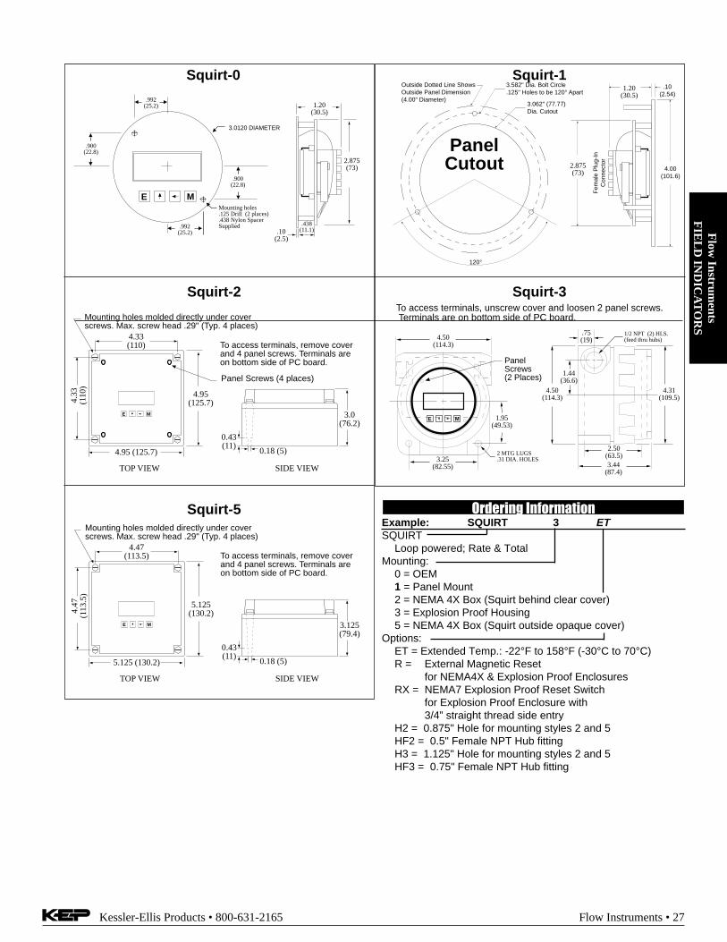
4.95(125.7)
4.95 (125.7)
4.33
(110
)
4.33(110)
Mounting holes molded directly under coverscrews. Max. screw head .29" (Typ. 4 places)
TOP VIEW
E M 3.0(76.2)
0.18 (5)
0.43(11)
SIDE VIEW
To access terminals, remove coverand 4 panel screws. Terminals areon bottom side of PC board.
Panel Screws (4 places)
E M
3.0120 DIAMETER
.900(22.8)
.992(25.2)
Mounting holes.125 Drill (2 places).438 Nylon SpacerSupplied
1.20(30.5)
2.875(73)
.10(2.5)
.438(11.1)
.900(22.8)
.992(25.2)
.10(2.54)
3.062" (77.77)Dia. Cutout
Fem
ale
Plu
g-In
Con
nect
or
4.00(101.6)
3.582" Dia. Bolt Circle.125" Holes to be 120° Apart
Outside Dotted Line ShowsOutside Panel Dimension(4.00" Diameter)
120°
PanelCutout
1.20(30.5)
2.875(73)
Squirt-1Squirt-0
Squirt-3Squirt-2
.75(19)
1.44(36.6)
4.50(114.3)
2.50(63.5)3.44
(87.4)
4.31(109.5)
1/2 NPT (2) HLS.(feed thru hubs)
E M
4.50(114.3)
1.95(49.53)
3.25(82.55)
2 MTG LUGS.31 DIA. HOLES
PanelScrews(2 Places)
To access terminals, unscrew cover and loosen 2 panel screws. Terminals are on bottom side of PC board.
Squirt-5
5.125(130.2)
5.125 (130.2)
4.47
(113
.5)
4.47(113.5)
Mounting holes molded directly under coverscrews. Max. screw head .29" (Typ. 4 places)
TOP VIEW
E M 3.125(79.4)
0.18 (5)
0.43(11)
SIDE VIEW
To access terminals, remove coverand 4 panel screws. Terminals areon bottom side of PC board.
Ordering InformationExample: SQUIRT 3 ETSQUIRT
Loop powered; Rate & TotalMounting:
0 = OEM1 = Panel Mount2 = NEMA 4X Box (Squirt behind clear cover)3 = Explosion Proof Housing5 = NEMA 4X Box (Squirt outside opaque cover)
Options:ET = Extended Temp.: -22°F to 158°F (-30°C to 70°C)R = External Magnetic Reset
for NEMA4X & Explosion Proof EnclosuresRX = NEMA7 Explosion Proof Reset Switch
for Explosion Proof Enclosure with3/4” straight thread side entry
H2 = 0.875" Hole for mounting styles 2 and 5HF2 = 0.5" Female NPT Hub fittingH3 = 1.125" Hole for mounting styles 2 and 5HF3 = 0.75" Female NPT Hub fitting

Flo
w I
nstr
umen
tsF
IEL
D I
ND
ICA
TO
RS
28 • Flow Instruments Kessler-Ellis Products • 800-631-2165
Features• Magnetic Pickup Input, Contact Closure Input,
DC Pulse Input (Optically Isolated)
• Displays Rate & Total Simultaneously
• 4 1/2 Digit Rate Display, 8 Digit TotalizerDisplay
• 4-20mA Analog Output Option
• Powered From Internal Battery, External DCSupply or 4-20 mA Output Loop
• 10 Pt. Linearization
• New & Improved Isolated Scaled Pulse Output
• Intrinsically Safe Option
• New, Attractive NEMA4 Wall Mount Enclosure
DescriptionFeaturing 41/2 digits of rate and 8 digits of total, the BAT R/T is a battery powered indicator capable of acceptingmagnetic pickup, DC pulse and switch closure inputs. Theunit can be ordered with an optional 4-20mA output. TheBAT R/T uses the 4-20mA loop to provide power when thisoutput is used.
SpecificationsPower:BATTERY POWERED
Supplied with 2 C size Lithium battery pack.EXTERNAL POWER INPUT
Voltage: 8.5 to 30 VDCCurrent: Less than 5 mASupplied with 1 C size lithium batteryProtection: Reverse Polarity Protection on DC PowerInput
LOOP POWEREDVoltage: 8.5 to 30 VDCSupplied with 1 or 2 C size lithium battery(ies)Protection: Reverse Polarity Protection on Current LoopLoop Burden: 8.5V maximum
Battery Life Expectancy
Idle 2hrs/day 8hrs/day 24hrs/day
A 5 yrs 4.5 yrs 3.5 yrs 2.1 yrs
A 4 5 yrs 3.7 yrs 2.7 yrs 1.5 yrs
B/C 2.5 yrs 2.25 yrs 1.75 yrs 1 yrStandby Operation
B/C 10 yearsExternal or Loop Power
RUN TIME
All of the above values are calculated with the pulse output ON.Turn the pulse output OFF to prolong battery life up to 30%.
BATRT
BATRT
BATRT
BATRT
Battery PoweredRatemeter & TotalizerBAT R/T
Display:Rate Display: (selectable decimal)
4.5 Digits (19999), 0.35" High, Display updates onceevery two secondsRate Descriptors: /SEC, /MIN, /HR (/DAY optional)Min. Input Frequency: .125 Hz to 10 Hz (selectable de-lay of 0.1 to 8.0 seconds)
Totalizer Display: (selectable decimal)8 Digits (99999999), 0.2" HighTotalizer Descriptors: GAL, LIT, FT3, M3, "blank"
(BBL optional)Warning Displays: Low battery warning "BAT"Pulse Output:
The pulse output advances with the least significant digitof the totalizer or decimal multiples there of (see Pulseoutput divider).Type: Isolated photomos relayMax. voltage (off state): 30 VDCCurrent (on state): 100mAPulse Duration: Selectable (see below)Pulse Output Rate: Selectable (see below)
SPEED (HZ) 1 2 4 8Min. on/off (msec) 500 250 125 62.5
Pulse output divider: User selectable, ÷1, ÷10, ÷100 orOFF
NOTE: Select OFF for max. battery life.
Mounting Styles:0- Circuit Board- OEM option (consult factory)1- Panel Mount - NEMA 4X Front2- Wall Mount - NEMA 4X Enclosure with BAT R/T
mounted behind clear cover3- Explosion Proof - Class I, Division I, Groups B, C & D
Class II, Division I, Groups E, F & G5- Wall Mount - NEMA 4X with keypad mounted
outside opaque cover

Flow
Instruments
FIE
LD
IND
ICA
TO
RS
Kessler-Ellis Products • 800-631-2165 Flow Instruments • 29
Typical Wiring:
RemoteReset Switch
12 VDCPowerSupply
+
-
1 Mag Input 12 Mag Input 23 Shield/GND4 Reset Input5 Contact Input6 Common/ DC In (-)
Turbine Meter withMag Pickup
6 5
4 3
2 1
MAG INPUT / DC POWERED
4-20mA (+)/DC In (+) 124-20mA (-) 11
Opto Input (+) 10Opto Input (-) 9Opto Out (+) 8Opto Out (-) 7
78
910
1112
KEP115-12
orExt. Battery
Flowmeter withSwitch Closure Output4-20mA (+)/DC In (+) 12
4-20mA (-) 11Opto Input (+) 10
Opto Input (-) 9Opto Out (+) 8Opto Out (-) 7
1 Mag Input 12 Mag Input 23 Shield/GND4 Reset Input5 Contact Input6 Common/ DC In (-)
6 5
4 3
2 1
CONTACT INPUT / PULSE OUTPUT / BATTERY POWERED
123456
78
910
1112
+
+-
1 Mag Input 12 Mag Input 23 Shield/GND4 Reset Input5 Contact Input6 Common/ DC In (-)
6 5
4 3
2 1
-
To ShieldPin 3
Flowmeterwith DC Pulse Output
+ -Strip ChartRecorder
24 VDCPowerSupply
+ -
ISOLATED INPUT / 4-20mA LOOP POWERED
NOTE: Separate power suppliesare not required
4-20mA (+)/DC In (+) 124-20mA (-) 11
Opto Input (+) 10Opto Input (-) 9Opto Out (+) 8Opto Out (-) 7
78
910
1112
24 VDCPowerSupplyKEP
115-24
KEP115-24
RemoteReset Switch
1 Mag Input 12 Mag Input 23 Shield/GND4 Reset Input5 Contact Input6 Common/ DC In (-)
Turbine Meter withMag Pickup
6 5
4 3
2 1
MAG INPUT / BATPACK POWERED
4-20mA (+)/DC In (+) 124-20mA (-) 11
Opto Input (+) 10Opto Input (-) 9Opto Out (+) 8Opto Out (-) 7
78
910
1112
BATPACK PLUGINCONNECTOR
BATPACK
Environmental:OPERATING TEMPERATURE
-4°F (-20°C) to + 158°F (70°C)Extended Temp: -22°F (-30°C) to + 158°F (70°C)
HUMIDITY0 - 90% Noncondensing
Accuracy:0.01% Reading, ±1 countTemperature Drift:
50 ppm/°C Worst CaseInputs:MAGNETIC PICKUP INPUT
Frequency Range: 0 to 3500 HzTrigger Sensitivity: 30 mV p-pOver Voltage Protected: ± 30 VDC
OPTO-ISOLATED DC PULSE INPUTHigh (logic 1): 4-30 VDCLow (logic 0): Less Than 1 VDCMinimum Current: .5 mAHysteresis: 0.4 VDCFrequency Range: 0 to 5 kHzMin. Pulse Width: 0.1 msec
CONTACT CLOSURE INPUT (contact closure to common)Internal Pullup Resistor: 100 KΩ to +3.6 VDCHigh (logic 1): Open or 4-30 VDCLow (logic 0): Less Than .5 VDCInternal Switch Debounce Filter: 0 to 40 Hz
RESET INPUT (contact closure to common)Internal Pullup Resistor: 100 KΩ to +3.6 VDCHigh (logic 1): Open or 4-30 VDCLow (logic 0): Less Than .5 VDCMinimum On : 25 msec
K-FACTORRange: 0.001 to 59999 (divider)Decimal Point Locations: XX.XXX to XXXXX
10 Point Linearization OptionThis feature allows the user to enter 10 different frequencieswith 10 different corresponding K-Factors to linearize non lin-ear signals.
Analog Output Option:Type: 4-20 mA follows rate display, Two wire hookupAccuracy: 0.15% Full Scale at 20° CTemperature Drift:
50 ppm/°C Typical200 ppm/°C Worst Case
Reverse Polarity ProtectedNOTE:The BAT R/T uses the 4-20 mA loop power as its power
source when this option is used.Listing: CE Compliant,
CSA(NRTL/C)(File No. LR91109) (x-proof only)UL IS Pending

Flo
w I
nstr
umen
tsF
IEL
D I
ND
ICA
TO
RS
30 • Flow Instruments Kessler-Ellis Products • 800-631-2165
4.63(117)
3/4 NPT(2) HLS
5.00(127)
5/16
4.25(108)
5.25(133)
E M
5.00(127)
To access terminals, unscrew cover and loosen 2 panel screws.(If screws are removed, spacers may drop out.) Terminals are onbottom side of PC board.
Optional 3rdConduit Entry
4.92(125)
4.92(125)
4.33(110)
4.33(110)
#8 Screw Mounting holes molded directly under coverscrews. Max. screw head .29" (Typ. 4 places)
TOPVIEWPANEL INSTALLED
E M
.98(25)
1.97(50)
.18(5)
.43(11)
SIDE VIEW
To access terminals, remove coverand 4 panel screws. Terminals areon bottom side of PC board.
Panel Screws
BATRT-3
BATRT-2
3.062" (77.77)Dia. Cutout
3.582" Dia. Bolt Circle.125" Holes to be 120° Apart
Outside Dotted Line ShowsOutside Panel Dimension(4.00" Diameter)
120°
.10(2.54)
4.00(101.6)
1.7(43)
2.875(73)
PanelCutout
BATRT-0
BATRT-1
E M
3.0120 DIAMETER
.900(22.8)
.992(25.2)
Mounting holes.125 Drill (2 places).438 Nylon SpacerSupplied
1.8(46)
2.875(73)
.10(2.5)
.438(11.1)
.900(22.8)
.992(25.2)
2.40(61)
2.20 (56)
0.95
(24)
0.30 max. (7.6)
0.15 (3.8)Battery
Mounting Hole0.125 (3) dia.
BATPACK
BATRT-5
5.10(130)
5.10(130)
4.45(113)
4.45(113)
Mounting holes molded directly under coverscrews. Max. screw head .29" (Typ. 4 places)
TOPVIEWPANEL INSTALLED
E M
1.1(28)
1.97(50)
.18(5)
.36(9.2)
SIDE VIEW
To access terminals, remove cover.Terminals are on bottom side of PC board.
Ordering InformationEXAMPLE: BATRT 3 A 4 ETSeries:Mounting:* 0 = OEM* 1 = Panel Mount
2 = NEMA 4X Box (Bat R/T behind clear cover)3 = Explosion Proof Housing5 = NEMA 4X Box (Bat R/T outside opaque cover)6 = Double Ended Explosion Proof Housing
Power Supply:* A = Battery (2 supplied)
B = External Power Supply (8.5 to 30 VDC)C = Loop Powered with 4-20 mA OutputAC = Loop Powered with 4-20 mA Output and 2 Batteries
Options (Multiple Options Available)4 = 10 Point LinearizationD = Rate per Day , Hour or MinuteET = Extended Temp.: -22°F to 158°F (-30°C to 70°C)CE = CE Approved VersionCSA = CSA Approved Version (explosion proof)IS** = Intrinsically SafeTRX = NEMA7 Explosion Proof Reset SwitchRN = External Magnetic ResetT = Third Conduit Entry in Ex-Proof HousingH2 = 0.875" Hole for mounting styles 2 and 5HF2 = 0.5" Female NPT Hub fittingH3 = 1.125" Hole for mounting styles 2 and 5HF3 = 0.75" Female NPT Hub fitting
Accessories:BATPACK= External Battery Pack with Two C Size
Batteries & 12" leadsBATC = Single Battery: Tadiran P/N TL2200/S
3.6V 5500mAh or equal115-24 = 115 VAC to 24 VDC power supply
* External battery pack supplied with models BATRT0A & BATRT1A** Contact factory for latest information

Flow
Instruments
FIE
LD
IND
ICA
TO
RS
Kessler-Ellis Products • 800-631-2165 Flow Instruments • 31
Features• Magnetic Pickup Input, Contact Closure Input,
DC Pulse Input (Optically Isolated)
• Displays Rate & Total Simultaneously
• 4 1/2 Digit Rate Display, 8 Digit Totalizer Display
• 4-20mA Analog Output (optional)
• Powered From Internal Battery, External DCSupply or 4-20 mA Output Loop
• 10 Pt. Linearization
• Isolated Alarm Output
• Intrinsically Safe Option
• New, Attractive NEMA4 Wall Mount Enclosure
DescriptionFeaturing 41/2 digits of rate and 8 digits of total, the BAT RAT is a batterypowered indicator with flow rate alarm output. It is capable of acceptingmagnetic pickup, DC pulse and switch closure inputs. The unit can beordered with an optional 4-20mA output. The BAT RAT uses the 4-20mA loop to provide power when this output is used.
SpecificationsPower:BATTERY POWERED
Supplied with 2 C size Lithium battery pack.EXTERNAL POWER INPUT
Voltage: 8.5 to 30 VDCCurrent: Less than 5 mASupplied with 1 C size lithium batteryProtection: Reverse Polarity Protection on DC Power Input
LOOP POWEREDVoltage: 8.5 to 30 VDCSupplied with 1 C size lithium batteryProtection: Reverse Polarity Protection on Current LoopLoop Burden: 8.5V maximum
Display:Rate Display: (selectable decimal)
4.5 Digits (19999), 0.35" High, 2 sec. display update rateRate Descriptors: /SEC, /MIN, /HRMin. Input Frequency: .125 Hz to 10 Hz
Totalizer Display: (selectable decimal)8 Digits (99999999), 0.2" HighTotalizer Descriptors: GAL, LIT, FT3, M3, "blank"
Warning Displays: Low battery warning "BAT"Alarm Output:Combination High-Low flow rate alarm output activates when flow
rate is less than low set point or greater than high set point.Type: Opto-isolated open collector transistor.
Max. voltage (off state): 100 VDCCurrent (on state): 100 mA
Mounting Styles:0- Circuit Board- OEM option (consult factory)1- Panel Mount - NEMA 4X Front2- Wall Mount - NEMA 4X Enclosure with BAT RAT
mounted behind clear cover3- Explosion Proof - Class I, Division I, Groups B, C & D
Class II, Division I, Groups E, F & G5- Wall Mount - NEMA 4X with keypad mounted
outside opaque cover
Battery Powered Ratemeter& Totalizer with Alarm OutputBAT RAT
Environmental:OPERATING TEMPERATURE
-4°F (-20°C) to + 158°F (70°C)Extended Temp: -22°F (-30°C) to + 158°F (70°C)
HUMIDITY0 - 90% Noncondensing
Accuracy:0.01% Reading, ±1 countTemperature Drift: 50 ppm/°C Worst Case
Inputs:MAGNETIC PICKUP INPUT
Frequency Range: 0 to 3500 HzTrigger Sensitivity: 30 mV p-pOver Voltage Protected: ± 30 VDC
OPTO-ISOLATED DC PULSE INPUTHigh (logic 1): 4-30 VDCLow (logic 0): Less Than 1 VDCMinimum Current: .5 mAFrequency Range: 0 to 5 kHzMin. Pulse Width: 0.1 msec
CONTACT CLOSURE INPUT (contact closure to common)Internal Pullup Resistor: 100 KΩ to +3.6 VDCHigh (logic 1): Open or 4-30 VDCLow (logic 0): Less Than .5 VDCInternal Switch Debounce Filter: 0 to 40 Hz
RESET INPUT (contact closure to common)Internal Pullup Resistor: 100 KΩ to +3.6 VDCHigh (logic 1): Open or 4-30 VDCLow (logic 0): Less Than .5 VDCMinimum On : 25 msec
K-FACTORRange: 0.001 to 59999 (divider)Decimal Point Locations: XX.XXX to XXXXXMultiplier: 1, 10, 100, 1000
10 Point Linearization OptionThis feature allows the user to enter 10 different frequencies with10 different corresponding K-Factors to linearize non linear sig-nals.
Analog Output Option:Type: 4-20 mA follows rate display, Two wire hookupAccuracy: 0.15% Full Scale at 20° CTemperature Drift:
50 ppm/°C Typical (200 ppm/°C Worst Case)Reverse Polarity Protected
NOTE: The BAT RAT uses the 4-20 mA loop power as its powersource when this option is used.
Listing: CE Compliant,CSA(NRTL/C)(File No. LR91109) (x-proof only)ULIS Pending

Flo
w I
nstr
umen
tsF
IEL
D I
ND
ICA
TO
RS
32 • Flow Instruments Kessler-Ellis Products • 800-631-2165
4.63(117)
3/4 NPT(2) HLS
5.00(127)
5/16
4.25(108)
5.25(133)
E M
5.00(127)
To access terminals, unscrew cover and loosen 2 panel screws.(If screws are removed, spacers may drop out.) Terminals are onbottom side of PC board.
Optional 3rdConduit Entry
4.92(125)
4.92(125)
4.33(110)
4.33(110)
#8 Screw Mounting holes molded directly under coverscrews. Max. screw head .29" (Typ. 4 places)
TOPVIEWPANEL INSTALLED
E M
.98(25)
1.97(50)
.18(5)
.43(11)
SIDE VIEW
To access terminals, remove coverand 4 panel screws. Terminals areon bottom side of PC board.
Panel Screws
BATRAT-3
BATRAT-2
3.062" (77.77)Dia. Cutout
3.582" Dia. Bolt Circle.125" Holes to be 120° Apart
Outside Dotted Line ShowsOutside Panel Dimension(4.00" Diameter)
120°
.10(2.54)
4.00(101.6)
1.7(43)
2.875(73)
PanelCutout
BATRAT-0
BATRAT-1
E M
3.0120 DIAMETER
.900(22.8)
.992(25.2)
Mounting holes.125 Drill (2 places).438 Nylon SpacerSupplied
1.8(46)
2.875(73)
.10(2.5)
.438(11.1)
.900(22.8)
.992(25.2)
2.40(61)
2.20 (56)
0.95
(24)
0.30 max. (7.6)
0.15 (3.8)Battery
Mounting Hole0.125 (3) dia.
BATPACK
BATRAT-5
5.10(130)
5.10(130)
4.45(113)
4.45(113)
Mounting holes molded directly under coverscrews. Max. screw head .29" (Typ. 4 places)
TOPVIEWPANEL INSTALLED
E M
1.1(28)
1.97(50)
.18(5)
.36(9.2)
SIDE VIEW
To access terminals, remove cover.Terminals are on bottom side of PC board.
Ordering InformationEXAMPLE: BATRAT 3 A 4 ETSeries:Mounting:* 0 = OEM* 1 = Panel Mount
2 = NEMA 4X Box (Bat R/T behind clear cover)3 = Explosion Proof Housing5 = NEMA 4X Box (Bat R/T outside opaque cover)6 = Double Ended Explosion Proof Housing
Power Supply:* A = Battery (2 supplied)
B = External Power Supply (8.5 to 30 VDC)C = Loop Powered with 4-20 mA OutputAC = Loop Powered with 4-20 mA Output and 2 Batteries
Options (Multiple Options Available)4 = 10 Point LinearizationET = Extended Temp.: -22°F to 158°F (-30°C to 70°C)CE = CE Approved VersionCSA = CSA Approved Version (explosion proof)IS** = Intrinsically SafeTRX = NEMA7 Explosion Proof Reset Switch
on Third Conduit EntryRN = External Magnetic ResetT = Third Conduit Entry in Ex-Proof HousingH2 = 0.875" Hole for mounting styles 2 and 5HF2 = 0.5" Female NPT Hub fittingH3 = 1.125" Hole for mounting styles 2 and 5HF3 = 0.75" Female NPT Hub fitting
Accessories:BATPACK= External Battery Pack with
Two C Size Batteries & 12" leadsBATC = Single Battery: Tadiran P/N TL2200/S
3.6V 5500mAh or equal115-24 = 115 VAC to 24 VDC power supply
* External battery pack supplied with models BATRAT0A &BATRAT1A
** Contact factory for latest information

Flow
Instruments
FIE
LD
IND
ICA
TO
RS
Kessler-Ellis Products • 800-631-2165 Flow Instruments • 33
DescriptionFeaturing 5 digits of resettable total and 8 digits of grand total, theBAT D/T is a battery powered indicator capable of acceptingmagnetic pickup, DC pulse and switch closure inputs.
SpecificationsPOWER:BATTERY POWERED
Supplied with 2 C size Lithium battery pack.EXTERNAL POWER INPUT
Voltage: 8.5 to 30 VDCCurrent: Less than 5 mASupplied with 1 C size lithium batteryProtection: Reverse Polarity Protection on DC Power Input
LOOP POWEREDVoltage: 8.5 to 30 VDCSupplied with 1 or 2 C size lithium battery(ies)Protection: Reverse Polarity Protection on Current LoopLoop Burden: 8.5V maximum
DISPLAY:Resettable Total Display
5 Digits (99999), 0.35" High, Display updates once every twoseconds
Grand Totalizer Display: (selectable decimal)8 Digits (99999999), 0.2" HighTotalizer Descriptors: GAL, LIT, FT3, M3, "blank"
Warning Displays: Low battery warning "BAT"ACCURACY:
±1 countListing: CE Compliant,
CSA(NRTL/C)(File No. LR91109) (x-proof only)UL IS Pending
PULSE OUTPUT:The pulse output advances with the least significant digit of thetotalizer or decimal multiples thereof (see Pulse outputdivider).Type: Isolated photomos relayMax. voltage (off state): 30 VDCCurrent (on state): 100mAPulse Duration: 62.5 mSec (max. output speed: 8 Hz)Pulse output divider: User selectable, ÷1, ÷10, ÷100 or OFF
NOTE: Select OFF for max. battery life.MOUNTING STYLES:0- Circuit Board- OEM option (consult factory)1- Panel Mount - NEMA 4X Front2- Wall Mount - NEMA 4X Enclosure with BAT D/T
mounted behind clear cover3- Explosion Proof - Class I, Division I, Groups B, C & D
Class II, Division I, Groups E, F & G5- Wall Mount - NEMA 4X with keypad mounted outside
opaque coverENVIRONMENTAL:OPERATING TEMPERATURE
-4°F (-20°C) to + 158°F (70°C)Extended Temp: -22°F (-30°C) to + 158°F (70°C)
HUMIDITY0 - 90% Noncondensing
INPUTS:MAGNETIC PICKUP INPUT
Frequency Range: 0 to 3500 HzTrigger Sensitivity: 30 mV p-pOver Voltage Protected: ± 30 VDC
OPTO-ISOLATED DC PULSE INPUTHigh (logic 1): 4-30 VDCLow (logic 0): Less Than 1 VDCMinimum Current: .5 mAHysteresis: 0.4 VDCFrequency Range: 0 to 5 kHzMin. Pulse Width: 0.1 msec
CONTACT CLOSURE INPUT (contact closure to common)Internal Pullup Resistor: 100 KΩ to +3.6 VDCHigh (logic 1): Open or 4-30 VDCLow (logic 0): Less Than .5 VDCInternal Switch Debounce Filter: 0 to 40 Hz
RESET INPUT (contact closure to common)Internal Pullup Resistor: 100 KΩ to +3.6 VDCHigh (logic 1): Open or 4-30 VDCLow (logic 0): Less Than .5 VDCMinimum On : 25 msec
Battery Life Expectancy
Idle 2hrs/day 8hrs/day 24hrs/day
BATDT 5 yrs 4.5 yrs 3.5 yrs 2.1 yrs
BATDT A 4 5 yrs 3.7 yrs 2.7 yrs 1.5 yrs
BATDT 2.5 yrs 2.25 yrs 1.75 yrs 1 yrStandby Operation
BATDT B or C 10 years
RUN TIME
All of the above values are calculated with the pulse output ON.Turn the pulse output OFF to prolong battery life up to 30%.
External or Loop Power
B or C
A or AC
Features• Magnetic Pickup Input, Contact Closure Input,
DC Pulse Input (Optically Isolated)
• Displays 5 Digit Resettable Total8 Digit Grand Total
• Powered From Internal Battery, External DCSupply or 4-20 mA Output Loop
• 10 Pt. Linearization
• New & Improved Isolated Scaled Pulse Output
• Intrinsically Safe Option
• New, Attractive NEMA4 Wall Mount Enclosure
Battery, Loop or DC PoweredDual TotalizerBAT D/T

Flo
w I
nstr
umen
tsF
IEL
D I
ND
ICA
TO
RS
34 • Flow Instruments Kessler-Ellis Products • 800-631-2165
DIMENSIONS:
4.63(117)
3/4 NPT(2) HLS
5.00(127)
5/16
4.25(108)
5.25(133)
E M
5.00(127)
To access terminals, unscrew cover and loosen 2 panel screws.(If screws are removed, spacers may drop out.) Terminals are onbottom side of PC board.
Optional 3rdConduit Entry
4.92(125)
4.92(125)
4.33(110)
4.33(110)
#8 Screw Mounting holes molded directly under coverscrews. Max. screw head .29" (Typ. 4 places)
TOPVIEWPANEL INSTALLED
E M
.98(25)
1.97(50)
.18(5)
.43(11)
SIDE VIEW
To access terminals, remove coverand 4 panel screws. Terminals areon bottom side of PC board.
Panel Screws
BATDT-3
BATDT-2
3.062" (77.77)Dia. Cutout
3.582" Dia. Bolt Circle.125" Holes to be 120° Apart
Outside Dotted Line ShowsOutside Panel Dimension(4.00" Diameter)
120°
.10(2.54)
4.00(101.6)
1.7(43)
2.875(73)
PanelCutout
BATDT-0
BATDT-1
E M
3.0120 DIAMETER
.900(22.8)
.992(25.2)
Mounting holes.125 Drill (2 places).438 Nylon SpacerSupplied
1.8(46)
2.875(73)
.10(2.5)
.438(11.1)
.900(22.8)
.992(25.2)
2.40(61)
2.20 (56)
0.95
(24)
0.30 max. (7.6)
0.15 (3.8)Battery
Mounting Hole0.125 (3) dia.
BATPACK
BATDT-5
5.10(130)
5.10(130)
4.45(113)
4.45(113)
Mounting holes molded directly under coverscrews. Max. screw head .29" (Typ. 4 places)
TOPVIEWPANEL INSTALLED
E M
1.1(28)
1.97(50)
.18(5)
.36(9.2)
SIDE VIEW
To access terminals, remove cover.Terminals are on bottom side of PC board.
K-FACTORRange: 0.001 to 59999Decimal Point Locations: XX.XXX to XXXXX
10 Point Linearization OptionThis feature allows the user to enter 10 different frequencieswith 10 different corresponding K-Factors to linearize nonlinear signals.
ANALOG OUTPUT OPTION:Type: 4-20 mA follows flow rate, Two wire hookupScaling: scaled per second, minute or hour.
0.000 to 59999 (selectable decimal)Accuracy: 0.15% Full Scale at 20° CTemperature Drift:
50 ppm/°C Typical200 ppm/°C Worst Case
Reverse Polarity ProtectedNOTE:The BAT D/T uses the 4-20 mA loop power as its power
source when this option is used. The battery is stillrequired to power the display.

Flow
Instruments
FIE
LD
IND
ICA
TO
RS
Kessler-Ellis Products • 800-631-2165 Flow Instruments • 35
RemoteReset Switch
1 Mag Input 12 Mag Input 23 Shield/GND4 Reset Input5 Contact Input6 Common/ DC In (-)
Turbine Meter withMag Pickup
6 5
4 3
2 1
MAG INPUT / BATPACK POWERED
4-20mA (+)/DC In (+) 124-20mA (-) 11
Opto Input (+) 10Opto Input (-) 9Opto Out (+) 8Opto Out (-) 7
78
910
1112
BATPACK PLUGINCONNECTOR
BATPACK
RemoteReset Switch
12 VDCPowerSupply
+
-
1 Mag Input 12 Mag Input 23 Shield/GND4 Reset Input5 Contact Input6 Common/ DC In (-)
Turbine Meter withMag Pickup
6 5
4 3
2 1
MAG INPUT / DC POWERED
DC In (+) 12Do Not Use 11
Opto Input (+) 10Opto Input (-) 9Opto Out (+) 8Opto Out (-) 7
78
910
1112
KEP115-12
orExt. Battery
Flowmeter withSwitch Closure Output4-20mA (+)/DC In (+) 12
4-20mA (-) 11Opto Input (+) 10
Opto Input (-) 9Opto Out (+) 8Opto Out (-) 7
1 Mag Input 12 Mag Input 23 Shield/GND4 Reset Input5 Contact Input6 Common/ DC In (-)
6 5
4 3
2 1
CONTACT INPUT / PULSE OUTPUT / BATTERY POWERED
123456
78
910
1112
Turbine Meter withMag Pickup
1 Mag Input 12 Mag Input 23 Shield/GND4 Reset Input5 Contact Input6 Common/ DC In (-)
6 5
4 3
2 1
MAG INPUT / 4-20mA LOOP POWERED
4-20mA (+)/DC In (+) 124-20mA (-) 11
Opto Input (+) 10Opto Input (-) 9Opto Out (+) 8Opto Out (-) 7
78
910
1112
24 VDCPowerSupply
+-
KEP115-24
Strip ChartRecorder
+-
TYPICAL APPLICATIONS Ordering InformationEXAMPLE: BATDT 3 A 4 ETSeries:Mounting:* 0 = OEM* 1 = Panel Mount
2 = NEMA 4X Box (Bat D/T behind clear cover)3 = Explosion Proof Housing5 = NEMA 4X Box (Bat D/T outside opaque cover)6 = Double Ended Explosion Proof Housing
Power Supply:* A = Battery (2 supplied)
B = External Power Supply (8.5 to 30 VDC)C = Loop Powered with 4-20 mA OutputAC = Loop Powered with 4-20 mA Output
and 2 BatteriesOptions (Multiple Options Available)
4 = 10 Point LinearizationET = Extended Temp.: -22°F to 158°F (-30°C to 70°C)CE = CE Approved VersionCSA = CSA Approved Version (explosion proof)IS** = Intrinsically SafeTRX = NEMA7 Explosion Proof Reset SwitchRN = External Magnetic ResetT = Third Conduit Entry in Ex-Proof HousingH2 = 0.875" Hole for mounting styles 2 and 5HF2 = 0.5" Female NPT Hub fittingH3 = 1.125" Hole for mounting styles 2 and 5HF3 = 0.75" Female NPT Hub fitting
Accessories:BATPACK= External Battery Pack with
Two C Size Batteries & 12" leadsBATC = Single Battery: Tadiran P/N TL2200/S
3.6V 5500mAh or equal115-24 = 115 VAC to 24 VDC power supply
* External battery pack supplied with models BATDT0A & BATDT1A** Contact factory for latest information

Flo
w I
nstr
umen
tsR
AT
EM
ET
ER
S/T
OT
AL
IZE
RS
36 • Flow Instruments Kessler-Ellis Products • 800-631-2165
Ratemeter / Totalizer TutorialWhat is a Rate/Totalizer Indicator? This is a general purpose instrument which conditions the electrical signal generated
by the flowmeter and scales the resulting flow information into a flow rate and flow total display in the units of measure desired bythe end user. Additional functionality such as alarms, analog output, pulse output, and serial communications may also be pro-vided. Also see the section on flow computers. See the figure below for a typical system configuration.
What capabilities should I look for to ensure compatibility with my type of flowmeter? Rate/Totalizers are availableto work with most flowmeter types and most common electrical signals produced by flowmeters. Begin by selecting aninstrument(s) that will accept the signal provided by the flowmeter. In some cases an amplifier or signal conditioner may benecessary. Next decide whether linearization will be required within the Rate/Totalizer and how the calibration will be representedwithin the instrument. Also determine if the Rate/Totalizer can provide the correct power required to operate the flow sensor (ifneeded).
What are basic areas of concern? Most customers begin a selection by looking for the instrument that has the type ofinformation display they prefer, that will work with the available power, and is available in a package which can be mounted in thedesired location.
What is an analog output and why is it used? Flow rate information is usually sent from one system to another as a 4-20mA signal. Some instruments permit the user to select what item of information is to be sent on the analog output. The corre-sponding span is user programmable. Additional features include programmable damping and user selectable ranges.
What is a pulse output and why is it used? Flow total information is usually sent from one system to another as a pulsewhich represents a quantity of flow. The remote system may sum these pulses to compute the flow total. Attributes of a pulseoutput include provisions for user scaling of the amount of flow each pulse represents, and the width of the pulse. Specificationswill usually list the electrical drive ratings for the pulse output.
What is an alarm output and why is it used? Relays are often used as controls to activate alarms. A alarm will usuallyinclude a provision for setting the alarm point. Additional features may include a programmable delay before the alarm will activate,an programmable alarm duration, and/or a programmable alarm hysteresis.
What are remote inputs and how are they used? Often there is a need to connect a remote switch near the operator forsuch purposes as remote reset, or remote print. Many Rate/Totalizers offer a variety of capabilities as remote inputs.
What is serial communications and why is it used? Serial communications is used to transmit information betweentwo computers, or between a computer and a printer. There are several commonly used standard hardware interfaces. TheseInclude RS-232, RS-422, and RS-485. There are also a variety of communication protocols, or message formats, which are used.Some of these are unique to the equipment manufacturer, others are industry standards. See also the section on communicationsolutions.
What is temperature compensation? In some cases the temperature may also be used to estimate the fluid densityfrom stored fluid properties. Many customers prefer to correct their flow readings to the equivalent mass or corrected volume at adesired reference temperature.
What are other areas of concern? Many areas where rate/totalizer indicators are installed are out of doors or arelocated in hazardous areas. Special purpose enclosures are available for many instruments to ensure that the equipment will beprotected in these environments. A NEMA-4 rating is weather proof. A NEMA-7 rating is explosion proof.
Typical Ratemeter/Totalizer Application
Flowmeterwith DC pulse output
Pulse Output
Alarm A
Alarm B
4-20 mA Out toStrip Chart Recorder
RS-485 orRS-232 toComputer
1 2 3 4 5 6
Pulse Output toRemote Totalizer
STOP
STARTPRINT
5
0 –
TIME
CLEAR
•
MENU
ENTERHELP
4PRE 1
3RATE
2TOTAL
1
GRAND6
SCROLL7
PRE 28 9

Flow
Instruments
RA
TE
ME
TE
RS/T
OT
AL
IZE
RS
Kessler-Ellis Products • 800-631-2165 Flow Instruments • 37
Features
• 6 digit, LED display with very high luminosity0.315" (8mm) digit height
• DIN housing, 1.88"x.944" (48x24mm)
• Easy programming with only 2 buttons
• Connection with screw terminal
• IP65 NEMA 4X (front)
• DC Powered
525K,529K & 530K Rate and Total Indicatorswith Pulse or Analog Inputs
525KTotalizer and Ratemeter
• Display range 0..999999 with leading zero blanking• Overflow condition will be indicated by 1 Hz flashing of rate
value and leading zeros of totalizer• Count frequency up to 10kHz• Indicates rate / sec or min (1/Tau)• SET-key resets the counter to zero (can be disabled in the
setup)• key to switche rate / total display• 1 count input• 1 reset input• Seperate multiplying factors counter /tachometer
(0.00001...99.9999)• Operating mode: Rate meter: 1/Tau (average value at higher
frequencies)
Order #: 525K.2
529K & 530KAnalog Displays
• Display range-19999..0..99999 with leading zero blanking
• Resolution 14 bit• 5 digit rate display; 6 digit total display (530K)• 4 different resolutions (0..20mA; 4..20mA; 0..10V or 2..10V)• Scaling factor for displayed value• Automatic storage of maximum and minimum value (can be
disabled in setup)• Input to activate storing of displayed value
Listing: UL listed (file#: E128604)
Order #:529K.2 = Rate Display Only530K.2 = Rate and Total Display
Electrical characteristics:• Supply Voltage: 10 to 30 VDC (50 mA)• Data retention: EEPROM (1 million cycles or 10 years)• Noise immunity acc. to EN 50081-2; EN55011 class B;
EN 50082-2• Ambient temperature: 14°F to 122°F (-10°C to +50°C)
1.234560.944"(24mm)
.1.88"(48mm)
0.866"x1.77"(22x45mm)
2.32"(59mm)
0.255"(6.5mm)
0.157"(4mm)
0.759"max.(19.3mm)
1 2 3 4 5 6 7
Panel Cutout: 0.876" x 1.78" (22.3 x 45.2mm)or 0.99" x 1.97" (25 x 50mm) with adaptor provided
• Input sensitivity: Low: 0 to 1 VDC High: 4 to 30 VDC (525K)• Input resistance: 10 k ohm (525K)• Polarity of inputs: programmable for all inputs in common• Optocoupler: Max 30VDC, 10 mA, 1V drop @ 10 mA

Flo
w I
nstr
umen
tsR
AT
EM
ET
ER
S/T
OT
AL
IZE
RS
38 • Flow Instruments Kessler-Ellis Products • 800-631-2165
INTELLECT-69 Ratemeter / TotalizerFrom Analog Inputs
Features• High/Low Scaling From Front Panel
• 2 Set Points Assignable To Rate Or Total
• Display Rate (pressure, level, watts, etc.),Peak & Valley and Integrated Total
• 0-5V, 0-10V, 1-5V, 4-20mA or 0-20mAAnalog Input
• NEMA 4X/IP 65 Front Panel
• +24V Output Power For Peripherals
• RS422/232 Serial Communications (optional)
• 4-20mA Output (optional)
• Square Root Extraction (optional)
• Rate Per Day Feature (optional)
Description:Featuring 6 digits of bright, 7-segment LED displays, theIntellect-69 is an integrating totalizer/ratemeter which acceptsanalog signal inputs. The unit can be field programmed toaccept 4-20mA, 0-20mA, 0-5V, 0-10V or 1-5V signals. Anoptional Square Law input is available for inputs that requiresquare root extraction. A 4-20mA output option is available tocontrol strip recorders or to transmit linear signal otherperipherals. Two assignable set points are standard. The highand low scaling settings are programmable from the front panel.By pressing the "view" button, the unit will display: integratedtotal, rate, peak or valley. Press the "lock" key once to freezethe display. RS422 or RS232 serial communications areavailable options for data communication with a host computer.Specifications:Display: 6 digit, .55" high, 7 segment, red orange, LED.Input Power: 110, 220 VAC ± 15% or 12 to 24VDC.Current: max. 300 mA DC or 10.0 VA at rated AC voltage.Output Power: (AC powered units only) + 24VDC @ 50mAregulated ±5%Temperature:Operating: +41°F (5°C) to +130°F (+54°C).Storage: -40°F (-40°C) to +200°F (93°C).Humidity: 0-90% NoncondensingMemory: EEPROM stores data for ten years if power is lost.Reset:Front Panel: resets displayed values and control outputs.Remote: 4-30VDC positive edge, resets totalizer and controloutputs.Input:Standard: Linear 4-20mA, 0-20mA, 0-5V, 0-10V or 1-5Vselectable from the front panel.Optional: Square Law 4-20mA, 0-20mA, 0-5V, 0-10V or 1-5V isavailable for inputs that require square root extraction.Input Impedance: Current: 100Ω; Voltage: 115KΩOvervoltage Protection: 50 VOvercurrent Protection: 50 mAResolution: 14.5 Bits
Listing: CE Compliant, CSA (File No. LR91109),NRTL/C pending
Calibration: The unit does all of the calibrations internally. Thereare no potentiometers to adjust and the unit never needs to beremoved from the case.Control Outputs:Standard: Open collector sinks 250mA from 30VDC whenactive.Optional: 2 each Form C SPDT 5 Amp @ 120/240 VAC or 28VDC.Set Points: The two control set points can be set at any numberfrom 0 to 59999. The set point outputs can be assigned to rate ortotal. The unit comes standard with two open collector controloutputs. Two 5 Amp, Form C relays are optional. The outputs areprogrammable from .01 to 599.99 sec or latched until reset whenassigned to the total and a hysteresis (alarm range) whenassigned to the rate.Rate Display: Updates 4 times per second, Accurate to 4.5 digits.Set "low" greater than "high" for inverted display (LINEAR ONLY).A user programmable low cutoff inhibits indications at low flowrates.Totalizer: Integrates from the rate reading and accumulates up to6 digits of total count. A totalizer divider allows the total to bedivided by 1, 10, 100 or 1000. This feature is especially useful forusers who deal with high total volumes.Analog Output: The unit can be ordered with an optional 4-20mAoutput which is proportional to the rate display. The high and lowsettings are programmable from the front panel. Set "low" greaterthan "high" for inverted output. A sinking driver generates acorresponding linear current through the external devices. Theoutput updates with each update of the rate. Accuracy is ±.25% FSworst case. Compliance voltage must be 3 to 30 VDC noninductive. (The unit can provide the DC source as long as the dropacross the devices being driven does not exceed 21V).

Flow
Instruments
RA
TE
ME
TE
RS/T
OT
AL
IZE
RS
Kessler-Ellis Products • 800-631-2165 Flow Instruments • 39
Programming: Decimal points, Scaling from 0 to 59999units per selected time base, set points, input type, securitylock code, and assigning outputs are all programmable fromthe front panel.Housing: Standard 1/8 DIN, high impact ABS plastic case(NEMA 4X/IP65 front panel).Shipping Weight: 2 lbs.Accuracy:RANGE % FS ERROR % FS ERROR
(worst case) (typical)
0-20 mA 0.1% .05%4-20 mA 0.1% .05%0-10 VDC 0.2% 0.1%0-5 VDC .25% .15%1-5 VDC .25% .15%
Square Law: (above 5% of bottom range) 0.1%(5V inputs .4%) Worst case over complete range: 2%
Temperature Stability: Will not drift more than 20 partsper million per °C from 5°C to 54°C
WIRING:
Dimensions:
4.44(112.7)
2.63
(66.
8)
3.93(99.8)
3.62(92)
1.77
(45)
0.6(15)
4.35(110.5)
GASKET
CUSTOMER PANELPanel Thickness 0.062" (1.5)to 0.187" (4.7) max.
1•Reset In2•Analog Out (Sink)3•Signal GRD (-DC)4•(Current) +I in5•(Voltage) +V in6•Not Used7•+24V Out8•Preset B Collector9•Preset A Collector10•+DC In11•110/220 VAC12•110/220 VAC
13•Common14•N.C.15•N.O.16•Common17•N.C.18•N.O.
Relay A
Relay B
Flowmeter(0-10 V Transmitter)
110 VAC60/50 Hz
•3 -
Sign
al G
ND
(-D
C)
. •5 -
V
In +
(Vol
tage
). •7
- +2
4V O
ut. •1
1 - A
C In
•12
- A
C In
-
+signal
Flowmeter(4-20mA Transmitter)
110 VAC60/50 Hz
•3 -
Sign
al G
ND
(-D
C)
•4 -
I In
+ (C
urre
nt)
. •7 -
+24V
Out
. •1
1 -
A
C In
•12
-
A
C In
-
+
2-Wire 4-20mA Transmitter
3-Wire 0-10V Transmitter
Ordering InformationExample: INT69RT A L 1 A C1Series:
INT69RT= Ratemeter / TotalizerINT69R= Ratemeter OnlyINT69T= Totalizer Only
Operating Voltage:A= 110 VAC ± 15% or 12 to 24 VDCB= 220 VAC ± 15% or 12 to 24 VDC
Inputs:L= Linear (standard)S= Square Law (optional)
Control outputs:1= 2 - Open Collector Outputs (standard)2= 2 - 5 Amp Form C Relays (optional)
Options (Multiple Options Available)A= Analog Output (4-20 mA)D= Rate per Day, Hour or MinuteC1= RS 232 communicationsC2= RS 422 communications
AccessoriesXHV - Explosion proof housing (see accessories section)NEMA-1/8DIN- NEMA 4X enclosure (see accessories section)Separate non keyboard panel order #34235Separate keyboard panel - order #34234

Flo
w I
nstr
umen
tsR
AT
EM
ET
ER
S/T
OT
AL
IZE
RS
40 • Flow Instruments Kessler-Ellis Products • 800-631-2165
Low Cost, Pulse InputTotalizer/RatemeterMRT (MINITROL)
Features
• CSA Approved
• Separate Scaling Factors For A & B Inputs
• Display Rate & Total
• Pulse Input - 10 kHz Max.
• RS422/RS232 Serial Communication
• Modbus RTU RS422/RS485/RS232
• NEMA 4X / IP65 Front Panel
• Separate Add/Subtract Simultaneous Inputs
• Quadrature & U/D Direction Control Inputs
Specifications:Display: 6 digit, 0.55" High LEDInput Power:
110 VAC ± 15% or 12 to 15 VDC220 VAC ± 15% or 12 to 15 VDC24VAC ± 15% or 12 to 15 VDC
Current: 250 mA DC max. or 6.5 VA ACOutput Power: (AC powered units only)+12 VDC @ 50 mA, unregulated -10 + 50%Temperature:Operating:
+32°F (0°C) to +130 F (+54°C)Storage:
-40 F (-40°C) to +200°F (93°C)Humidity: 0-90% NoncondensingMemory: EEPROM stores data for 10 years if power is lost.Inputs:3: High Impedance DC pulse input 4-30 VDC (high),
Open or 0-1 VDC (low), 10 KΩ imp. 10 kHz max.speed. Accepts simultaneous inputs. May be usedwith KEP 711 series or 715-1 encoders or PD & Dseries sensors.
3M: Mag. Input, Input A only, accepts 30mV input (50 Vmax. P/P) signals 10 KΩ imp. 5 kHz max. (Input B, 4-30V)
3MB: Mag. Input, Inputs A & B, accepts 30mV input (50 Vmax. P/P) signals 10 KΩ imp. 5 kHz max.
5: 4-30 V Count pulses on Input A, 4-30 V DirectionControl input (level) on Input B. May be used withKEP 715-2 Encoder.
5M: 30 mV Count pulses on Input A (50 V max. P/P) 4-30V Direction Control input (level) on Input B.
9: Quadrature, accepts 4-30 V pulses with 90° phaseshift for direction detection. May be used with KEP716 encoder.
9MB: Quadrature, accepts 30 mV (50 V max. P/P) pulseswith 90° phase shift for direction detection.
Application:Any rate, total or blending application where 2 preset alarmsand scaling are required.
Description:The MINITROL is a 6 digit totalizer / ratemeter with twolevel, 5 digit preset alarm control of total or rate. Inputs A &B have separate scaling K-factors. The totalizer can beprogrammed for “A” subtract “B”, “A” add “B” or A & B asseparate totalizers, with display and control of the “net” totaland rate of "A". The MINITROL is also available in 4 otherversions. MC2: a two preset totalizer with scaling, MR2: ahigh/low alarm ratemeter with scaling; The “MC”: a totalizingcounter only, and the “MR”: a rate meter display only. If onlyone input is required, the unit will display the total and ratefrom that one channel. The MINITROL can accept up to10,000 pulses per second. It has a 5 digit floating decimalscale factor allowing total readout in true engineering unitsand rate per second, minute or hour.Input “A” simultaneously drives a ratemeter which can beprogrammed to display the basic frequency (rate per sec-ond) or factored to show rate per minute or rate per hour.Simply push the “VIEW” button to see either total or ratewithout losing a count. Two separate 5 A relay contacts canbe set to operate at either rate or total presets in a latch orauto-recycle mode with output timing from 0.1 to 99.9 sec-onds.Two control outputs can be assigned to either the totalizeror ratemeter and can automatically recycle at the batch orstay latched until reset.Up to 99 units can communicate to a host computer on asingle RS232 or RS422 loop.When two inputs are received (A & B), the unit can eitheradd or subtract the two inputs or display the two inputs asseparate totalizers.
• 30mV Magnetic Pickup Inputs
• 4-20mA or 0-20mA Analog Output

Flow
Instruments
RA
TE
ME
TE
RS/T
OT
AL
IZE
RS
Kessler-Ellis Products • 800-631-2165 Flow Instruments • 41
Approvals: CSA File# LR91109-7, CE ApprovedReset:Front Panel:
Resets displayed value and control outputRemote:
4-30 VDC (75 - 240 V AC/DC, Input 8) negative edgeresets Totalizer "A" and control output
Control Outputs:Relays:
2 each N.O. Relay; 5 Amps 120/240 VAC or 28 VDC.(N.C. relay contacts and NPN transistor outputavailable with solder jumpers. Transistor output isinternally pulled up to 10 VDC through relay coil, sinksfrom 10 VDC to .5 V @ 100 mA)
Analog Output:An optional 4-20mA (0-20mA) output is available forthe Minitrol series. The output can be programmedto track rate or total. This feature is available byadding suffix A to the part number. Connections arevia a 2 terminal pluggable screw connector.Programming is accomplished by using the front panelin conjunction with rear dip switches.Accuracy: ±.25% FS worst case.Compliance Voltage: 3 to 30 VDC non inductive.
Scaling Factor (K-Factor): In the standard unit, a userprogrammable K-Factor is used to convert the input pulsesto engineering units. The 5 digit K-Factor dividers, withdecimal keyed into any position, allow easy direct entry ofany K-Factor from 0.0001 to 99999. Separate factors maybe entered for the 2 separate input channels.Presets: Two control outputs are provided. To set relayvalues, press “menu” button until “Relay” appears on thedisplay, the A and B outputs can be assigned to the rateme-ter (high/low), one preset for rate and one for total, or twopresets (2 stage shut off) on the A and B totalizers. A 5digit value can be entered for both presets and the deci-mal point location is the same as the counter. The outputscan be set to energize from 0.1 to 99.9 seconds or latch(0.0). If a value other than 0.0 is entered, the totalizers willauto reset at the preset . In the A-B or A+B versions, therelays will be assigned to either net total or A rate.Lockout: Unauthorized front panel changes can be pre-vented by entering a user selected 5 digit code in the“LOC” mode. The front panel can be completely lockedout or the presets can remain accessible.
Ratemeter: Accuracy: 0.01% FS (±1 display digit). The rate display updates once per second. The ratemeter can be programmed to accept almost any numberof pulses per unit of measurement, sample from 2 to 24seconds maximum, and auto-range up to 5 digits of sig-nificant information. In the “RPS” mode, the ratemeterdisplays in units per second, and in the “scale” mode,units per hour or per minute. The unit will display the rateof the A Input only.Totalizer: The two 6-digit totalizers can count at 10 kHzmax. Each can have a 5-digit dividing scale factor. Thetotalizer advances on the positive edge of each pulse.Count up or down modes available, as are quadratureinputs from encoders for position or flow measurement.The unit can be programmed to view the net value of"A+B" or "A-B", or A and B as separate totalizers.RS232/RS422 with KEP Protocol:If the serial interface option is supplied, up to 99 units canbe linked together. (The terminal addressing the unit mustbe capable of driving all loads in the loop.) Unit status andnew set points can be communicated by serial communi-cation. Mode changes, however, must always be made onthe front panel.Data is received and transmitted over standard EIA RS232or RS422 levels. Unit number, baud rate and parity areentered in the “Program Setting” set up mode and remainin memory even if power is off.RS232/RS422/RS485 with Modbus RTU Protocol:The serial port can be used for serial printing or also fordata acquisition. The unit can address up to 247 units(The terminal addressing the unit must be capable of drivingall loads in the loop.) The unit can communicate with amaster device through a Modbus-RTU protocol. The datagiven for each parameter is in IEEE float format comprisingof 2 words. The unit can be connected in a network.
Device ID: 01-247Baud Rates: 300, 600, 1200, 2400, 4800, 9600Parity: None, Odd, EvenProtocol: Modbus RTU (Half Duplex)
Termination:
1- COMMON
2- N.O.(N.C./NPN)
3- COMMON
4- N.O.(N.C./NPN)
5- A INPUT
6- B INPUT
7- 12VDC OUT/+DC IN
8- -DC (GROUND)
9- RESET INPUT
10- NOT USED
11- A.C. INPUT
12- A.C. INPUT
RE
LA
YS
AB
13- V+
14- I SINK
AN
AL
OG
OU
TP
UT
ONCAL.
0-20mACOUNT
SET
OFFRUN
4-20mARATERUN1
2
3
4
ON
SW
ITC
H

Flo
w I
nstr
umen
tsR
AT
EM
ET
ER
S/T
OT
AL
IZE
RS
42 • Flow Instruments Kessler-Ellis Products • 800-631-2165
Mounting:
MINItrol (MRT, MC2, MR2)
Example: MRT A 3 1 ASeries:
MRT= 6 digit counter / 5 digit ratemeterwith presets and scaling.
MC2= 6 digits, counter only withpresets and scaling.
MR2= 5 digits, rate only withpresets and scaling.
Operating Voltage:A= 110 VAC ± 15% or 12 to 15 VDCB= 220 VAC ± 15% or 12 to 15 VDCC= 24 VAC ± 15% or 12 to 15 VDC
Count Inputs:3 = Standard, 4-30 VDC simultaneous inputs.3M = Mag. Input, Input A only, 30mV input
(Input B, 4-30V)3MB = Mag. Input, Inputs A & B, 30mV input5 = 4-30 V pulses on Input A,
4-30 V Direction Control input on Input B.5M = 30 mV pulses on Input A,
4-30 V Direction Control input on Input B9 = Quadrature, accepts 4-30 V pulses9MB = Quadrature, accepts 30 mV pulses (A & B)
Options (Multiple Options Not Available)1= RS232 Communications2= RS422 Communications3= Modbus RTU RS2324= Modbus RTU RS422/RS485A= Analog Output (4-20/0-20 mA)
AccessoriesSeparate non keyboard panel order #34235Separate keyboard panel - order #34237
MINItrol (MR, MC)
Example: MC H A 3 M (MR ONLY) 1Series:
MR= 5 digits, rate display onlyno presets, no scaling
MC= 6 digits, dual input,bi-directional counter only, no presets, no scaling
Input Speed:L = Low speed input debounce filter 40 Hz max.H = High speed input (0 to 9.99 kHz)
Operating Voltage:A= 110 VAC ± 15% or 12 to 15 VDCB= 220 VAC ± 15% or 12 to 15 VDCC= 24 VAC ± 15% or 12 to 15 VDC
Count Input:3 = Standard, 4-30 VDC simultaneous inputs.3M = Mag. Input, Input A only, 30mV input
(Input B, 4-30V)3MB = Mag. Input, Inputs A & B, 30mV input5 = 4-30 V pulses on Input A,
4-30 V Direction Control input on Input B.5M = 30 mV pulses on Input A,
4-30 V Direction Control input on Input B9 = Quadrature, accepts 4-30 V pulses9MB = Quadrature, accepts 30 mV pulses (A & B)
Rate Time Base: MR ONLYS= RPS (rate per second)M= RPM (rate per minute)H= RPH (rate per hour)
Options: (Multiple Options Not Available)1= RS232 Communications2= RS422 Communications
AccessoriesSeparate non keyboard panel order #34235Separate keyboard panel - order #34237
How To Order:
3.622(92)
1.772(45)
4.437(112.7)
2.625(66.68)
0.587(14.91)
4.245(107.8)
BEZELGASKET
CUSTOMER PANELPanel Thickness 0.062" (1.5)to 0.187" (4.7) max.
3.925(99.7)

Flow
Instruments
RA
TE
ME
TE
RS/T
OT
AL
IZE
RS
Kessler-Ellis Products • 800-631-2165 Flow Instruments • 43
MINITROL-SFeatures
• Separate Scaling Factors For Rate & Total
• Display Rate & Total
• 30mV Magnetic Pickup Inputs (optional)
• Count Inhibit Input
• Security Lockout
• RS422/RS232 Serial Communication (optional)
• NEMA 4X / IP65 Front Panel
• 4-20mA or 0-20mA Analog Output (optional)
• CSA Approved
Totalizer/Ratemeter withSeparate Scaling of Rate/Total
DESCRIPTION:The CSA approved totalizer and ratemeter each have their own 5digit dividing scale factor. The two 5 AMP preset relay outputs canbe programmed by the user to apply to the “A” total counter or the“A” ratemeter. The user can view the rate, total and grand total.The B relay can be used to create a scaled pulse output. Magneticpickup input, analog output and RS232 communication options areavailable.
SPECIFICATIONS:DISPLAY: 6 digit, 0.55" High LEDINPUT POWER:
110 VAC ± 15% or 12 to 15 VDC220 VAC ± 15% or 12 to 15 VDC24 VAC ± 15% or 12 to 15 VDC
CURRENT: 250 mA DC max. or 6.5 VA ACOUTPUT POWER (AC powered units only)
+12 VDC @ 50 mA, unregulated -10 + 50%TEMPERATURE:
Operating:+32°F (0°C) to +130 F (+54°C)Storage:-40 F (-40°C) to +200°F (93°C)
MEMORY: EEPROM stores data for 10 years if power is lost.INPUTS:
3: High Impedance DC pulse input 4-30 VDC (high), Open or0-1 VDC (low),10 KΩ imp. 10 kHz max. speed.
3M: Mag. Input, Rate/total input only, accepts 30mV input (50 Vmax. P/P) signals 10 KΩ imp. 5 kHz max. (Inhibit input,4-30V)
NOTE: The Mag. input has filtering as follows: 30mV triggerlevel up to 300Hz , 0.25 V trigger level at 5KHz
RESET:Front Panel: Resets displayed total value and control output.
Remote: 4-30 VDC (75-240 V AC/DC, Input 8) negativeedge resets total and relay control output.
NOTE: The remote reset does not reset the grand total.LISTING: CSA (File No. LR91109), CE Compliant ,
NRTL/C pendingK FACTOR/SCALING:
The K-Factors are used to convert the input pulses to engineeringunits. The 5 digit K-Factor dividers, with decimal keyed into anyposition, allow easy direct entry of any K-Factor from 0.0001 to99999. Separate factors may be entered for rate and total.
CONTROL OUTPUTS:Relays:
2 each N.O. Relay; 5 Amps120/240 VAC or 28 VDC.(N.C. relay contacts and NPN transistor outputavailable with solder jumpers.
Analog Output:An optional 4-20mA (0-20mA) output is available forthe Minitrol series. The output can be programmedto track rate or total. This feature is available byadding suffix A to the part number. Connections arevia a 2 terminal pluggable screw connector.Programming is accomplished by using the front panelin conjunction with rear dip switches.Accuracy: ± 0.25% FSCompliance Voltage: 3 to 30 VDC non inductive.
RS232/RS422 SERIAL INTERFACE:If the serial interface option is supplied, up to 99 units can belinked together. (The terminal addressing the unit must becapable of driving all loads in the loop.) Unit status and new setpoints can be communicated by serial communication. Modechanges, however, must always be made on the front panel.Data is transmitted at selected baud rates using standard sevenbit ASCII characters and parity with two additional bits of “Start”and “Stop” to make up the standard ten bit character.Data is received and transmitted over standard EIA RS232 orRS422 levels. Each 10 bit character is made up of a start bit, 7bit ASCII code, parity bit and stop bit. Unit number, baud rateand parity are entered in the “Program Setting” set up modeand remain in memory even if power is off.Note that the input impedance of RS232 is 3K or 7K Ohm worstcase. The terminal addressing the unit must be capable ofdriving all loads in the loop. RS422 input impedance is muchhigher and there is usually no problem driving 25 units. Unitserial transmit line remains in a high impedance “OFF” stateuntil addressed. A print list can be triggered by external switch.
PRESETS:Two control outputs are provided. To set relay A or B'sfunctionality, press “menu” button until “Relay” appears on thedisplay, the A and B outputs can be assigned to the rate alarm(high/low), or for total/grand total. A 5 digit value can be enteredfor both presets A and B. The decimal point location is the sameas the counter. The outputs can be set to energize from 0.1 to99.9 seconds or latch (0.0). If a value other than 0.0 is entered,the corresponding totalizer will auto reset at the preset. Thismay be used to create a relay scaled pulse output.

Flo
w I
nstr
umen
tsR
AT
EM
ET
ER
S/T
OT
AL
IZE
RS
44 • Flow Instruments Kessler-Ellis Products • 800-631-2165
LOCKOUT:Unauthorized front panel changes can be prevented byentering a user selected 5 digit code, in the “LOC" mode.The front panel can be completely locked out or the presetscan remain accessible.
RATEMETERAccurate to 4 1/2 digits (±1 display digit). The rate meter canbe programmed to:
• accept almost any number of pulses per unit ofmeasurement
• sample from 2 to 24 seconds maximum• auto-range up to 5 digits of significant information.
The display can be programmed to read in units per Second(sec), Minute (min), Hour (hour), or Day (day).
TOTALIZER:The two 6-digit totalizers can count at 10kHz speed. Theyshare a 5-digit dividing scale factor. The totalizer advanceson the positive edge of each pulse.
TYPICAL SENSOR HOOKUP:
1 C
OM
MO
N2
N.O
. (N
.C./
NP
N)
3 C
OM
MO
N4
N.O
. (N
.C./
NP
N)
5 A
IN
PU
T6I
NH
IBIT
TO
TAL
IN
PU
T7
12 V
OU
TP
UT
/ +
DC
IN
PU
T8
- D
C (
GR
OU
ND
)9
RE
SE
T I
NP
UT
10 N
OT
US
ED
11 A
C I
NP
UT
12 A
C I
NP
UT
OUTPUTPOWERGROUND
ARELAYS
B
*
* PULLUP RESISTOR REQUIRED FOR OPEN COLLECTOR OUTPUTS 4.7KΩ TYPICAL
Flowmeter
High Level Pulse
Low Level Pulse (Mag Pickup)
1 C
OM
MO
N2
N.O
. (N
.C./
NP
N)
3 C
OM
MO
N4
N.O
. (N
.C./
NP
N)
5 A
IN
PU
T6I
NH
IBIT
TO
TAL
IN
PU
T7
12 V
OU
TP
UT
/ +
DC
IN
PU
T8
- D
C (
GR
OU
ND
)9
RE
SE
T I
NP
UT
10 N
OT
US
ED
11 A
C I
NP
UT
12 A
C I
NP
UT
SIGNAL
GROUND
ARELAYS
B
Flowmeterwith Mag. Pickup
Dimensions: 3.925(99.7)
4.437(112.7)
2.625(66.68)
3.622(92)
1.772(45)
CUSTOMER PANELPanel Thickness 0.062" (1.5)to 0.187" (4.7) max.
0.587(14.91)
4.245(107.8)
BEZELGASKET
Ordering InformationExample: MRTS A 3 1Series:
MRTS= 6 digit counter / 5 digit ratemeterwith presets and scaling.
Operating Voltage:A= 110 VAC ± 15% or 12 to 15 VDCB= 220 VAC ± 15% or 12 to 15 VDCC= 24 VAC ± 15% or 12 to 15 VDC
Count Inputs:3 = Standard, 4-30 VDC simultaneous inputs.3M = Mag. Input, rate/total input only, 30mV input
(Inhibit input, 4-30V)Options
1= RS232 Communications2= RS422 Communications3= Modbus RTU RS2324= Modbus RTU RS422/RS485A= Analog Output (4-20/0-20 mA)CE = CE Compliant Version
NOTE: RS232/RS422 & Analog Output options can not be combined
AccessoriesXHV - Explosion proof housing (see accessories section)NEMA-1/8DIN- NEMA 4X enclosure (see accessories
section)P1000- Serial Printer (see accessories section)Separate non keyboard panel order #34235Separate keyboard panel - order #34234

Flow
Instruments
RA
TE
ME
TE
RS/T
OT
AL
IZE
RS
Kessler-Ellis Products • 800-631-2165 Flow Instruments • 45
Totalizer/Ratemeter for Paddle orPelton Wheel Turbine FlowmetersMINITROL-PW
Features
• Display Rate & TotalFlowrate Display = Input Frequency + Offset B
Factor A
• Pulse Input - 10 kHz Max.
• 30mV Magnetic Pickup Inputs (optional)
• Security Lockout
• RS422/RS232 Serial Communication (optional)
• NEMA 4X / IP65 Front Panel
• 4-20mA or 0-20mA Analog Output (optional)
• CSA Approved
DESCRIPTION:The Minitrol-PW is a single input counter/ratemeter intended foruse with low flow paddle or pelton wheel turbine flowmeters. Twoscale factors are used to describe the flowmeter calibrationcharacteristics. The two 5 AMP preset relay outputs can beprogrammed by the user to apply to the "A" total counter or the "A"ratemeter. The user can view the rate, total and grand total.
SPECIFICATIONS:DISPLAY: 6 digit, 0.55" High LEDINPUT POWER:
110 VAC ± 15% or 12 to 15 VDC220 VAC ± 15% or 12 to 15 VDC24 VAC ± 15% or 12 to 15 VDC
CURRENT: 250 mA DC max. or 6.5 VA ACOUTPUT POWER (AC powered units only)
+12 VDC @ 50 mA, unregulated -10 + 50%TEMPERATURE:
Operating:+32°F (0°C) to +130 F (+54°C)Storage:-40 F (-40°C) to +200°F (93°C)
MEMORY: EEPROM stores data for 10 years if power is lost.INPUTS:
3: High Impedance DC pulse input 4-30 VDC (high), Open or 0-1 VDC (low),10 KΩ imp. 10 kHz max. speed.
3M: Mag. Input, Rate/total input only, accepts 30mV input (50 Vmax. P/P) signals 10 KΩ imp. 5 kHz max. (Inhibit input, 4-30V)
NOTE: The Mag. input has filtering as follows: up to 300Hz@30mV, 5KHz @ .25V to 50V max.
INHIBIT TOTAL INPUTTerminal 6: 4-30 VDC level will inhibit totalization
RESET:Front Panel: Resets displayed value and control outputRemote: 4-30 VDC, negative edge resets Totalizer
(Total A) and control outputNOTE: The remote reset will not reset Grand Total (Total B)
Listing: CSA (File No. LR91109), CE Compliant ,NRTL/C pending
K FACTOR/SCALINGThe K-Factor is used to convert the input pulses to engineeringunits. The two 5 digit scale factors, with decimal keyed into anyposition, allow easy direct entry of any scaling factor from0.0001 to 99999. Factor A is used to enter the linearized K-Factor and Factor B is used to enter the offset frequency.
LOW FLOW CUTOFF:A low flow cutoff is provided to inhibit operation in low flow outof range regions.
CONTROL OUTPUTS:Relays:
The relays may be assigned to rate or total.2 each N.O. Relay; 5 Amps120/240 VAC or 28 VDC. (N.C. relaycontacts and NPN transistor output available with solder jumpers.
Analog Output:An optional 4-20mA (0-20mA) output is available for the Minitrolseries. The output can be programmed to track rate or total.This feature is available by adding suffix A to the part number.Connections are via a 2 terminal pluggable screw connector.Programming is accomplished by using the front panel inconjunction with rear dip switches.Accuracy: ± 0.25% FS worst case.Compliance Voltage: 3 to 30 VDC non inductive.
RS232/RS422 SERIAL INTERFACEIf the serial interface option is supplied, up to 99 units can belinked together. (The terminal addressing the unit must becapable of driving all loads in the loop.) Unit status and new setpoints can be communicated by serial communication. Modechanges, however, must always be made on the front panel.Data is transmitted at selected baud rates using standard sevenbit ASCII characters and parity with two additional bits of “Start”and “Stop” to make up the standard ten bit character.Data is received and transmitted over standard EIA RS232 orRS422 levels. Each 10 bit character is made up of a start bit, 7bit ASCII code, parity bit and stop bit. Unit number, baud rateand parity are entered in the “Program Setting” set up modeand remain in memory even if power is off.Note that the input impedance of RS232 is 3K or 7K Ohm worstcase. The terminal addressing the unit must be capable ofdriving all loads in the loop. RS422 input impedance is muchhigher and there is usually no problem driving 25 units. Unitserial transmit line remains in a high impedance “OFF” stateuntil addressed. A print list can be triggered by external switch.
PRESETSTwo control outputs are provided. To set relay values, press“menu” button until “Relay” appears on the display, the A and Boutputs can be assigned to the rate alarm (high/low), or for total(A) or grand total (B). A 5 digit value can be entered for bothpresets and the decimal point location is the same as thecounter. The outputs can be set to energize from 0.1 to 99.9seconds or latch (0.0). If a value other than 0.0 is entered, thetotalizers will auto reset at the preset. This may be used tocreate a relay pulse output instead of grand total.

Flo
w I
nstr
umen
tsR
AT
EM
ET
ER
S/T
OT
AL
IZE
RS
46 • Flow Instruments Kessler-Ellis Products • 800-631-2165
LOCKOUTUnauthorized front panel changes can be prevented byentering a user selected 5 digit code, in the “LOC” , . mode.The front panel can be completely locked out or the presetscan remain accessible.
RATEMETERAccurate to 4 1/2 digits (±1 display digit). The rate meter canbe programmed to accept almost any number of pulses perunit of measurement and auto-range up to 5 digits of significantinformation. The display can be programmed to read in unitsper Second (sec), Minute (min), Hour (hour), or Day (day).
COUNTERThe two 6-digit totalizers can count at 10kHz speed. Theyshare a 5-digit dividing scale factor. The totalizer performs asfollows:
If Freq. In > CutoffTotal increment = Freq. Offset • ∆ Time + Pulses In
K Factor A K Factor A
Rate = (Freqin + Freq offset) • time baseK Factor A
Time base: Sec =1, Min = 60, Hour = 3600, Day = 86400
If Freq. In < CutoffTotal Increment = 0Rate = 0
Total B (grand total) increments with Total A.
1 C
OM
MO
N2
N.O
. (N
.C./
NP
N)
3 C
OM
MO
N4
N.O
. (N
.C./
NP
N)
5 A
IN
PU
T6I
NH
IBIT
TO
TAL
IN
PU
T7
12 V
OU
TP
UT
/ +
DC
IN
PU
T8
- D
C (
GR
OU
ND
)9
RE
SE
T I
NP
UT
10 N
OT
US
ED
11 A
C I
NP
UT
12 A
C I
NP
UT
OUTPUTPOWERGROUND
ARELAYS
B
*
* PULLUP RESISTOR REQUIRED FOR OPEN COLLECTOR OUTPUTS 4.7KΩ TYPICAL
Flowmeter
High Level Pulse
Low Level Pulse(Mag Pickup)
1 C
OM
MO
N2
N.O
. (N
.C./
NP
N)
3 C
OM
MO
N4
N.O
. (N
.C./
NP
N)
5 A
IN
PU
T6I
NH
IBIT
TO
TAL
IN
PU
T7
12 V
OU
TP
UT
/ +
DC
IN
PU
T8
- D
C (
GR
OU
ND
)9
RE
SE
T I
NP
UT
10 N
OT
US
ED
11 A
C I
NP
UT
12 A
C I
NP
UT
SIGNAL
GROUND
ARELAYS
B
Flowmeterwith Mag. Pickup
TYPICAL SENSOR HOOKUP
Dimensions:
Ordering InformationExample: MRTPW A 3 1Series:
MRTPW= 6 digit counter / 5 digit ratemeterwith presets and scaling.
Operating Voltage:A= 110 VAC ± 15% or 12 to 15 VDCB= 220 VAC ± 15% or 12 to 15 VDCC= 24 VAC ± 15% or 12 to 15 VDC
Count Inputs:3 = Standard, 4-30 VDC simultaneous inputs.3M = Mag. Input, rate/total input only, 30mV input
(Inhibit input, 4-30V)Options
1= RS232 Communications2= RS422 CommunicationsA= Analog Output (4-20/0-20 mA)CE = CE Compliant Version
NOTE: RS232/RS422 & Analog Output options can not be combined
AccessoriesXHV - Explosion proof housing (see accessories section)NEMA-1/8DIN- NEMA 4X enclosure (see accessories section)P1000- Serial Printer (see accessories section)Separate non keyboard panel order #34235Separate keyboard panel - order #34234
3.925(99.7)
4.437(112.7)
2.625(66.68)
3.622(92)
1.772(45)
CUSTOMER PANELPanel Thickness 0.062" (1.5)to 0.187" (4.7) max.
0.587(14.91)
4.245(107.8)
BEZELGASKET
THEORY OF OPERATIONLow flow, Pelton Wheel turbine flowmeters have a transfercharacteristic which can best be represented by the followingequation for frequencies above the minimum usable flowratefor the device:
frequency = Klinearized • GPM – Offset Frequency60
Where: Klinearized and offset frequency are scaling constantsdetermined during flow sensor calibration.
This transfer characteristic applies within the metermanufacturers published range. Below some minimum flowmeter output frequency, the flow rate should be consideredas 0 and the totalization inhibited. This is called the "cutoff"frequency.
( )

Flow
Instruments
RA
TE
ME
TE
RS/T
OT
AL
IZE
RS
Kessler-Ellis Products • 800-631-2165 Flow Instruments • 47
2 Separate Rate/Total Displayswith Combination FunctionDRT(Dual rate/totalizer)
Features• Displays A,B,&C Rate & A,B,&C Total
• Separate Scaling Factors For A & B Inputs
• “C” Displays A+B, A-B, A÷B, & A÷A+B
• RS422/RS232 Serial Communication
• Modbus RTU RS422/RS485/RS232
• Pulse Input - 10 kHz Max.
• Security Lockout
• NEMA 4X / IP65 Front Panel
• 30mV Magnetic Pickup Inputs
MEMORY:EEPROM stores data for 10 years if power is lost.
INPUTS:3: High Impedance DC pulse input 4-30 VDC (high), Open or
0-1 VDC (low), 10 KΩ imp. 10 kHz max. speed. Acceptssimultaneous inputs. May be used with KEP 711 series orPD & D series sensors.
3M: Mag. Input, Input A only, accepts 30mV input (50 V max. P/P) signals 10 KΩ imp. 5 kHz max. (Input B, 4-30V)
3MB: Mag. Input, Inputs A & B, accepts 30mV input (50 V max.P/P) signals 10 KΩ imp. 5 kHz max.
RESET:Front Panel: Resets displayed value and control outputRemote: 4-30 VDC negative edge resets all counters,
"A" counter or "B" counter (user selectable).
K FACTOR/SCALINGThe DRT has two separate K-Factors that are used to convertthe input pulses to engineering units. The 5 digit K-Factordividers, with decimal keyed into any position, allow easy directentry of any K-Factor from 0.0001 to 99999. Separate factorsmay be entered for the 2 separate input channels.
CONTROL OUTPUTS:Relays:
2 each N.O. Relay; 5 Amps 120/240 VAC or 28 VDC.(N.C. relay contacts and NPN transistor outputavailable with solder jumpers. Transistor output isinternally pulled up to 10 VDC through relay coil, sinksfrom 10 VDC to .5 V @ 100 mA)
Analog Output:An optional 4-20mA (0-20mA) output is available forthe DRT. The output can be programmedto track rate or total of the C display. This feature is availableby adding suffix A to the part number. Connections arevia a 2 terminal pluggable screw connector.Programming is accomplished by using the front panelin conjunction with rear dip switches.Accuracy: 50uA worst case.Compliance Voltage: 3 to 30 VDC non inductive.
Approvals: CSA File# LR91109-7, CE Compliant
DESCRIPTION:The DRT (Dual Rate Totalizer) is a dual 5 digit Ratemeter 6 digitTotalizer in a 1/8 DIN package. User selects 1 of 6 displays toshow A,B or C rate and A,B or C total. Inputs A and B haveseparate scaling to read in engineering units.A 4-20mA (0-20mA) output of the C rate or total is optional.The user can press the VIEW button to see 6 separate items total A, total B, total C, rate A, rate B, rate C. Negative valuesare displayed with a negative symbol ( - 12345 ). For the C value,the user can choose from the following combination of A&Binputs: TOTAL; with a choice of A+B or A-B; RATIO with choiceof A÷B(x100) to show percent of A to B quantity or A÷[A+B(x100)]to show percent of A to total quantity.Two independent presets are standard. User selects whetheroutput A is activated by total or rate value of input A or selectedC. Output B can be activated by total or rate value of input B orselected C. Outputs activated by A or B total can be set to latchor autorecycle with an adjustable output duration from 00.1 to99.9 sec. For rate, ratio, or C total outputs pull in when value isequal or above the preset and drop out when value is below thepreset minus the selected 0 to 999 hysteresis.
SPECIFICATIONS:DISPLAY:6 digit, 0.55" High LED
INPUT POWER:110 VAC ± 15% or 12 to 15 VDC220 VAC ± 15% or 12 to 15 VDC24VAC ± 15% or 12 to 15 VDC
CURRENT:250 mA DC max. or 6.5 VA AC
OUTPUT POWER: (AC powered units only)+12 VDC @ 50 mA, unregulated -10 + 50%
TEMPERATURE:Operating: +32°F (0°C) to +130 F (+54°C)Storage: -40 F (-40°C) to +200°F (93°C)
HUMIDITY: 0-90% Noncondensing
• 4-20mA or 0-20mA Analog Output
• CSA Approved

Flo
w I
nstr
umen
tsR
AT
EM
ET
ER
S/T
OT
AL
IZE
RS
48 • Flow Instruments Kessler-Ellis Products • 800-631-2165
Mounting:
3.622(92)
1.772(45)
4.437(112.7)
2.625(66.68)
0.587(14.91)
4.245(107.8)
BEZELGASKET
CUSTOMER PANELPanel Thickness 0.062" (1.5)to 0.187" (4.7) max.
3.925(99.7)
1- COMMON
2- N.O.(N.C./NPN)
3- COMMON
4- N.O.(N.C./NPN)
5- A INPUT
6- B INPUT
7- 12VDC OUT/+DC IN
8- -DC (GROUND)
9- RESET INPUT
10- NOT USED
11- A.C. INPUT
12- A.C. INPUT
RE
LA
YS
AB
13- V+
14- I SINK
AN
AL
OG
OU
TP
UT
ONCAL.
0-20mACOUNT
SET
OFFRUN
4-20mARATERUN1
2
3
4
ON
SW
ITC
H
Terminals:
PRESETSTwo control outputs are provided. To set relay values, press“menu” button until “Relay” appears on the display, the A and Boutputs can be assigned to the A, B or C displays. A 5 digit valuecan be entered for both presets and the decimal point location isthe same as the counter. The outputs can be set to energize from0.1 to 99.9 seconds or latch (0.0). If a value other than 0.0 isentered, the counters will auto reset at the preset (for A&B counters).
LOCKOUTUnauthorized front panel changes can be prevented by enteringa user selected 5 digit code. The front panel can be completelylocked out or the presets can remain accessible.
RATEMETERAccurate to 4 1/2 digits (±1 display digit). The ratemeter uses 1/tau with 8 digit math, can sample from 2 to 24 seconds maxi-mum, and auto-range up to 5 digits of significant information. Inthe “RPS” mode, the ratemeter displays in units per second, andin the “scale” mode, units per hour or per minute. The unit willdisplay the rate of the A&B Inputs.
COUNTERThe two 5-digit counters can count at 10Khz speed. Each has aseporate 5-digit dividing scale factor. The counters advance onthe positive edge of each pulse. Besides being able to stepthrough the total and rate values of A & B inputs, the user can
see a selected combination of total and rate of A+B, A-B, A÷BX100(percent of A to B), A÷A+BX100 (percent of A to total). The unitcan be programmed to view the Total/Rate value of "A+B" & "A-B", or "A÷B" & "A÷A+B".
RS232/RS422 with KEP Protocol:If the serial interface option is supplied, up to 99 units can belinked together. (The terminal addressing the unit must be ca-pable of driving all loads in the loop.) Unit status and new setpoints can be communicated by serial communication. Modechanges, however, must always be made on the front panel.Data is received and transmitted over standard EIA RS232 orRS422 levels. Unit number, baud rate and parity are entered inthe “Program Setting” set up mode and remain in memory even ifpower is off.RS232/RS422/RS485 with Modbus RTU Protocol:The serial port can be used for serial printing or also for dataacquisition. The unit can address up to 247 units (The terminaladdressing the unit must be capable of driving all loads in theloop.) The unit can communicate with a master device through aModbus-RTU protocol. The data given for each parameter is inIEEE float format comprising of 2 words. The unit can beconnected in a network.
Device ID: 01-247Baud Rates: 300, 600, 1200, 2400, 4800, 9600Parity: None, Odd, EvenProtocol: Modbus RTU (Half Duplex)
Example: DRT A 3 1Series:
DRT= 6 digit counter / 5 digit ratemeterwith presets and scaling.
Operating Voltage:A= 110 VAC ± 15% or 12 to 15 VDCB= 220 VAC ± 15% or 12 to 15 VDCC= 24 VAC ± 15% or 12 to 15 VDC
Count Inputs:3 = Standard, 4-30 VDC simultaneous inputs.3M = Mag. Input, Input A only, 30mV input
(Input B, 4-30V)3MB = Mag. Input, Inputs A & B, 30mV input
Options: (Multiple Options Not Available)A= Analog Output (4-20/0-20 mA)1= RS232 Communications2= RS422 Communications3= Modbus RTU RS2324= Modbus RTU RS422/RS485
Accessories:Separate non keyboard panel order #34235Separate keyboard panel - order #34234
Ordering Information

Flow
Instruments
RA
TE
ME
TE
RS/T
OT
AL
IZE
RS
Kessler-Ellis Products • 800-631-2165 Flow Instruments • 49
Features
• EZ Setup Feature
• Setup Diskette
• Advanced Batching Features
• Menu Selectable Hardware Features
• Two Line LCD or VFD Display
• NEW! - 0-20mA or 4-20mA Analog Output
• NEW! - Attractive Wall Mount Enclosure
• Isolated Pulse Output Standard
• RS-232 Port Standard, RS-485 Optional
• Advanced Printing Cababilities
• Data Logging & Modem Remote MeteringSupport
• DIN Enclosure with Two Piece Connectors
• DDE Server & HMI Software Available
Economical Flow Totalizer,Ratemeter and BatcherSUPERtrol-I LE
Description:The SUPERtrol-I LE Flow Computer satisfies the instrumentrequirements for a variety of pulse producing flowmeter types inliquid applications.
The alphanumeric display shows measured and calculatedparameters in easy to understand format. Single key direct accessto measurements and display scrolling is supported. An EZ Setupfeature rapidly guides the user through the basic setup.
The SUPERtrol-I LE can be programmed for rate/total indication orbatching. The various pulse inputs and outputs can be “soft” assignedto meet a variety of common application needs. The user “softselects” the usage of each feature while configuring the instrument.A 0-20mA or 4-20mA analog output is standard.
The user can assign the standard RS-232 Serial Port for data logging,transaction printing, or for connection to a modem for remote meterreading. An optional RS-485 serial port using Modbus RTU protocolis available.
A Service or Test mode is provided to assist the user during start-upsystem check out by monitoring inputs and exercising outputs. Thesystem setup can also be printed.
Specifications:Environmental
Operating Temperature: 0°C to +50°CStorage Temperature: -40°C to +85 CHumidity : 0-95% Non-condensingMaterials: U.L. approved
Listing: UL/C-UL Listed (File No. E192404), CE CompliantDisplay
Type: 2 lines of 20 charactersTypes: Backlit LCD and VFD ordering optionsCharacter Size: 0.3" nominalUser programmable label descriptors and units of measure
KeypadKeypad Type: Membrane KeypadKeypad Rating: Sealed to Nema 4Number of keys: 16
EnclosureSize: See DimensionsDepth behind panel: 6.5" including mating connectorType: DINMaterials: Plastic, UL94V-0, Flame retardantBezel: Textured per matt finish
Power InputThe factory equipped power option is internally fused. An internalline to line filter capacitor and MOV are provided for added transientsuppression.110 VAC Power Option: 85 to 127 Vrms, 50/60 Hz220 VAC Power Option: 170 to 276 Vrms, 50/60 HzDC Power Option:
12 VDC (10 to 14 VDC)24 VDC (14 to 28 VDC)
Flow Inputs:Pulse Inputs:
Number of Flow Inputs: one (single or quadrature)Input Impedance: 10 KΩ nominalPullup Resistance: 10 KΩ to 5 VDC (menu selectable)Pull Down Resistance: 10 KΩ to commonTrigger Level: (menu selectable)
High Level InputLogic On: 3 to 30 VDCLogic Off: 0 to 1 VDC
Low Level Input (mag pickup)Sensitivity:
10 mV or 100 mVMinimum Count Speed:
User selectable (as low as 1 pulse/99 seconds)Maximum Count Speed:
Selectable: 40 Hz, 3000 Hz or 20kHzOvervoltage Protection: 50 VDCLinearization: Average K or 16 Point linearization with separate
forward and reverse tablesControl Inputs
Number of Inputs: 3Switch Inputs are menu selectable for Start, Stop, Reset, Lock,Inhibit, Alarm Acknowledge, Print or Not Used.Control Input SpecificationsInput Scan Rate: 10 scans per secondLogic 1: 4 - 30 VDCLogic 0: 0 - 0.8 VDCInput Impedance: 100 KΩControl Activation:
Positive Edge or Pos. Level based on product definition forswitch usage.
Excitation VoltageMenu Selectable: 5, 12 or 24 VDC @ 100 mA (fault protected)
Data LoggingThe data logger captures print list information to internal storagefor aproximately 1000 transactions. This information can be usedfor later uploading or printing. Storage format is selectable forComma-Carriage Return or Printer formats.
Trend, Alarm and Log
your SUPERtrol Data with
KEPware HMI Software!
See Special Flow Instruments Section
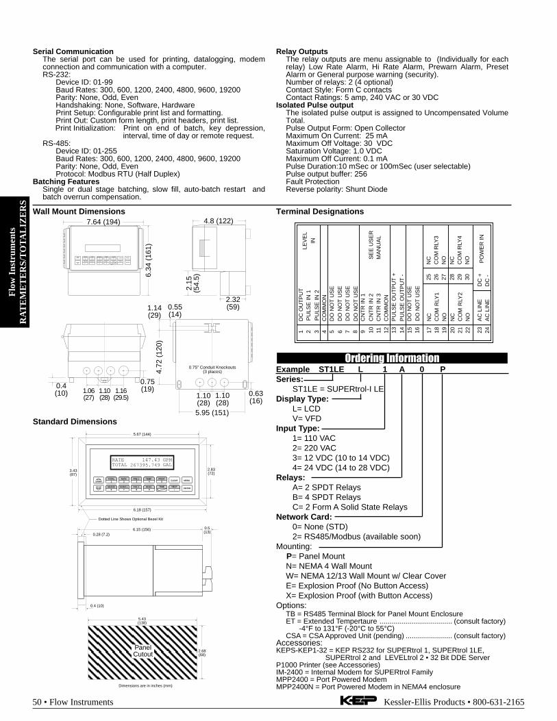
Flo
w I
nstr
umen
tsR
AT
EM
ET
ER
S/T
OT
AL
IZE
RS
50 • Flow Instruments Kessler-Ellis Products • 800-631-2165
Terminal Designations
Standard Dimensions5.67 (144)
2.83(72)
6.15 (156) 0.5(13)
0.28 (7.2)
3.43(87)
6.18 (157)
Dotted Line Shows Optional Bezel Kit
PanelCutout
5.43(138)
2.68(68)
Dimensions are in inches (mm)
0.4 (10)
STOP
STARTPRINT
5
0 –
TIME
CLEAR
•
MENU
ENTERHELP
TEMP4
PRE 13
RATE2
TOTAL1
GRAND6
SCROLL7
PRE 28
DENS9
RATETOTAL 267395.749
GPMGAL
147.43
13P
ULS
E O
UT
PU
T +
PU
LSE
OU
TP
UT
-
RLY
1
RLY
2
AC
LIN
EA
C L
INE
2418C
OM
19 20 21 22 23
NO
NC
CO
MN
O
14 15 16 17N
C
PO
WE
R IN
DC
-D
C +
DC
OU
TP
UT
CO
MM
ON
CN
TR
IN 1
CN
TR
IN 2
CN
TR
IN 3
CO
MM
ON
DO
NO
T U
SE
8 9 10 11 122 3 4 5 6 71
SE
E U
SE
RM
AN
UA
L
PU
LSE
IN 1
INLE
VE
L
PU
LSE
IN 2
DO
NO
T U
SE
DO
NO
T U
SE
DO
NO
T U
SE
DO
NO
T U
SE
DO
NO
T U
SE
CO
M R
LY3
CO
M R
LY4
26 27 28 29 30
NO
NC
NO
25N
C
Serial CommunicationThe serial port can be used for printing, datalogging, modemconnection and communication with a computer.RS-232:
Device ID: 01-99Baud Rates: 300, 600, 1200, 2400, 4800, 9600, 19200Parity: None, Odd, EvenHandshaking: None, Software, HardwarePrint Setup: Configurable print list and formatting.Print Out: Custom form length, print headers, print list.Print Initialization: Print on end of batch, key depression,
interval, time of day or remote request.RS-485:
Device ID: 01-255Baud Rates: 300, 600, 1200, 2400, 4800, 9600, 19200Parity: None, Odd, EvenProtocol: Modbus RTU (Half Duplex)
Batching FeaturesSingle or dual stage batching, slow fill, auto-batch restart andbatch overrun compensation.
Relay OutputsThe relay outputs are menu assignable to (Individually for eachrelay) Low Rate Alarm, Hi Rate Alarm, Prewarn Alarm, PresetAlarm or General purpose warning (security).Number of relays: 2 (4 optional)Contact Style: Form C contactsContact Ratings: 5 amp, 240 VAC or 30 VDC
Isolated Pulse outputThe isolated pulse output is assigned to Uncompensated VolumeTotal.Pulse Output Form: Open CollectorMaximum On Current: 25 mAMaximum Off Voltage: 30 VDCSaturation Voltage: 1.0 VDCMaximum Off Current: 0.1 mAPulse Duration:10 mSec or 100mSec (user selectable)Pulse output buffer: 256Fault ProtectionReverse polarity: Shunt Diode
Wall Mount Dimensions7.64 (194)
6.34
(16
1)
2.15
(54.
5)
2.32(59)
0.4(10) 1.06
(27)1.10(28)
1.16(29.5)
0.75(19)
1.10(28)
1.10(28)
5.95 (151)
0.63(16)
0.55(14)
1.14(29)
4.72
(12
0)
MENU
ENTER
TOTAL RATE
1 2
6 7
GRAND SCROLL
ALARM 1 TEMP
3 4
8 9
PRESALARM 2
PRINTCLEAR
5
0 - .
TIME HELP
4.8 (122)
0.75” Conduit Knockouts(3 places)
Ordering InformationExample ST1LE L 1 A 0 PSeries:
ST1LE = SUPERtrol-I LEDisplay Type:
L= LCDV= VFD
Input Type:1= 110 VAC2= 220 VAC3= 12 VDC (10 to 14 VDC)4= 24 VDC (14 to 28 VDC)
Relays:A= 2 SPDT RelaysB= 4 SPDT RelaysC= 2 Form A Solid State Relays
Network Card:0= None (STD)2= RS485/Modbus (available soon)
Mounting:P= Panel MountN= NEMA 4 Wall MountW= NEMA 12/13 Wall Mount w/ Clear CoverE= Explosion Proof (No Button Access)X= Explosion Proof (with Button Access)
Options:TB = RS485 Terminal Block for Panel Mount EnclosureET = Extended Tempertaure .................................... (consult factory)
-4°F to 131°F (-20°C to 55°C)CSA = CSA Approved Unit (pending) ....................... (consult factory)
Accessories:KEPS-KEP1-32 = KEP RS232 for SUPERtrol 1, SUPERtrol 1LE,
SUPERtrol 2 and LEVELtrol 2 • 32 Bit DDE ServerP1000 Printer (see Accessories)IM-2400 = Internal Modem for SUPERtrol FamilyMPP2400 = Port Powered ModemMPP2400N = Port Powered Modem in NEMA4 enclosure

Flow
Instruments
RA
TE
ME
TE
RS/T
OT
AL
IZE
RS
Kessler-Ellis Products • 800-631-2165 Flow Instruments • 51
KEPTROL R/T TOTALIZER / RATEMETERFeatures• Pulse or Analog Input
• Display Total, Rate or Grand Total
• Two Alarm Outputs, User Selectable for Total,Rate or Grand Total
• Pulse Input to 20 kHz Count Frequency
• K-Factor Programmable to 8 Places
• Two Stage Security Lockout
• Two Way RS232/422/ Communications Option
• NEMA 4X/IP 65 Front Panel
• Scalable Analog Output of Rate or Total
• 16 Point Linearization Option
Description:Featuring 8 digits of bright, .55", alpha-numeric display, the
pulse input version of the KEPtrol R/T can accept up to 20,000pulses per second. The analog input version accepts inputs,such as 4 to 20mA or 1 to 5V. The standard KEPtrol R/T has twoseparate, 8 digit, floating decimal, “K” factors to convert theinputs to meaningful total and rate data. An optional 16 point K-factor can linearize flow from meter outputs. The user, with thepush of a button, can toggle back and forth to view the total ofthe batch, the rate of flow and the grand total count. Two controloutputs can be assigned independently by the user to activate atpreset batch total, rate or grand total for .1 to 9.9 seconds or untilreset.
A scaled pulse output is also provided by an open collectordriver. Since the output frequency is user selectable at 10, 200,2K or 20K Hz, the unit can transmit the total data to remoteelectro-mechanical or electronic totalizers as well as computers,programmable controllers or other monitor equipment.
An optional analog output allows the user to select low andhigh settings to control strip chart recorders or other peripherals.Up to 15 units can be connected to optional RS232 or RS422communications port to set control points or access data. WithRS422M it is possible to communicate with up to 256 units on asingle serial link. This option is also compatible with Opto 22’sOptomux Network.
Specifications:Display: 8 Digit, .55" High, 15 Segment, Red Orange, LED.Input Power (Internally Fused)A: 110 VAC ±15% or 12 to 27 VDCB: 220 VAC ±15% or 12 to 27 VDCCurrent: Maximum 250 mA DC or 3.2 VA at rated AC voltage.Output Power: (On AC powered units only)+12 VDC at 100mA. Separate Isolated 12 VDC at 100mA toallow +12 VDC or +24 VDC regulated ±5% worst case.DC Outputs are supplied with resettable fuses.Memory: EEPROM stores all program and total data for mini-mum of 10 years if power is lost.Pulse Inputs:
3A: Standard, High impedance pulse input. Open or 0 to 1 VDC(low), 3 to 30 VDC (high), 10K Ohm impedance, 20 kHz max.input speed (min. on/off 25 µsec.).3B: Same as 3A but has 4.7K Ohm input pull up resistors to +5VDC on input for pulsing with contact to ground or NPN opencollector transistor.Analog Inputs:The current loop or voltage input is converted to a highly linear 0to 10 kHz frequency. This frequency can then be scaled by the 8digit K-Factors to total or display rate in separate engineeringunits.Accuracy over full temperature range:Zero error: +0.175% full scale max.Overall error: +0.5% full scale max.5A/7A: 4-20mA, 250 Ohm impedance5B/7B: 0-20mA, 250 Ohm impedance5C/7C: 1-5 VDC, 15K Ohm impedance5D/7D: 0-5 VDC, 15K Ohm impedance5E/7E: 0-10 VDC, 15K Ohm impedance6A: 4-20 mA, Square Law, 250 Ohm impedanceReset:Front push button: “Clear” resets displayed number and controloutput. Remote: 3 to 30 VDC positive edge resets the totalizerand control output. Impedance: 10K to ground (-DC)Minimum pulse: 5 msec.Temperature:Operating: +32°F (0°C) to +130°F (+54°C).Storage: -40°F (-40°C) to +200°F (+93°C).ET: Extended Temperature -40° to 158°F (-40° to 70° C)
ET not available with analog inputs or outputsHumidity: 0-90% NoncondensingListing: CE CompliantTotalizer: Each of the total and grand total counters have 8digits. In the set-up mode choose “R0” (reset to zero) for addingoperation or “SP” (set to preset) for subtracting operation. Whileviewing the total, the display can be made to flash the grand totalby pressing “ENT”. Activating “CLR” while the grand total isflashing, resets the grand total counter.

Flo
w I
nstr
umen
tsR
AT
EM
ET
ER
S/T
OT
AL
IZE
RS
52 • Flow Instruments Kessler-Ellis Products • 800-631-2165
Ratemeter: Accurate to 51/2 digits (+1 display digit). The ratemeter can be programmed to accept almost any number ofpulses per unit of measurement, sample from 2 to 24 secondsmaximum, and autorange up to 6 digits of significant information.The rate meter with a “K” factor of 1 displays the rate of pulsesper second. Simply dial in the proper “K” factor to display inminutes, hours or other units of measurement. Press the “C”button while the unit is displaying the total to display the rate; “R”is displayed on the left side of the display.Lockout: Two stage lockout available for allowing change ofpresets only or total lockout of front panel parameter changes.Unauthorized front panel changes can be prevented by enteringa user selected four digit code.Factored Output: The KEPtrol R/T gives one pulse out for eachfactored total count. Open collector sinks 30 VDC maximum to 1volt maximum at 100mA maximum. Output speed is user select-able (see table below). An internal buffer holds up to 10,000pulses for output at the selected frequency before “DATALOST”flashes, indicating pulses are lost. If factored rate exceeds 7digits “RFF…” flashes. These alarms indicate that speed hasbeen exceeded.
Speed(HZ) 10 200 2000 20000Min. on/off(msec) 47.5 2.0 0.2 0.013
Control Outputs: (Each of two outputs)1. NPN Transistor Version: (Optional)Open collector sinks max. 250mA from 30 VDC when active.2. SPDT Relay Version:10A 120/240 VAC or 28 VDC (Standard).Analog Output: Digital input or analog input (except SquareLaw) versions can be ordered with an analog output of the rateor total reading. User keys in the low and high settings at set-up.Current Outputs:A sinking driver generates a corresponding linear current throughthe external devices, updating with each update of the rate.Accuracy is ±.5% worst case. Compliance voltage must be 3 to24 VDC, non inductive. (The KEPtrol R/T can provide the DCsource as long as the drop across all devices being driven doesnot exceed 21 V).Voltage Outputs:When the voltage out option is ordered, a controlled voltageoutput is located at terminal 3 and referenced to pin 12 (ground).Accuracy is .1% @ 20°C ( max. drift .01%/C° ).Preset Alarms: Two control presets are provided on the KEPtrolR/T. The preset numbers can be made to flash without interrupt-ing the control function by pressing “A” (Preset A) or “B” (PresetB). Press “ENT” to return to rate or total display. Change thepreset by clearing the flashing preset number and keying in anew number before pressing the “ENT” button. (Count pulsesmay be lost if the preset is changed while pulses are coming in.)In the “Relay Set-Up” the user selects either or both presetoutputs to be activated by the total, grand total or rate. Ifselected for total or grand total the outputs can be set to activateat the preset total for 0.1 to 9.9 seconds or latch (0.0 setting)until reset. If selected for rate control, the rate will be comparedwith the preset at each display update and the output activated ifthe rate is equal to or greater than the preset. The output dropsout again only if the rate drops below the preset. If the rate goesout of scale the display will show all “F” and the output willremain in the state prior to going out of scale.K-Factor: In the standard unit a fixed K-Factor is used to convertthe input pulses or frequency generated internally by the analoginput to engineering units. The 8 digit K-Factor dividers, withdecimal keyed into any position, allow easy direct entry of any K-
Factor greater than 0.0001 to 99999999. Separate K-Factorsmay be entered for the total and rate section. Thus, you maybatch and total in gallons and display rate in liters per hour. Themaximum factored count speed is 20,000 Hz. The maximumfactored rate is 7 digits.16 POINT LINEARIZATION variable K-factor option makes flowsystems more accurate and often extends their usable range byallowing users to dial in different K-factors for different flow rates.It works with either pulse input or standard analog current loop orvoltage input. It is recommended for flow meters whose K-factors change with different rates of flow. From 3 to 16 points offrequency (0 to 10,000 Hz) and K-factors (.0001 to 999,999) aredialed in at set up. The unit uses 8 digit floating math tointerpolate between settings. Rate per second, per minute orper hour programmability eliminates the need to calculate sepa-rate K-factors for total and rate.Outcard: RS232 or RS422 serial two way communication op-tions are available. Several units can be linked together andaddressed separately to transmit unit status or accept new setpoints in the standard ASCII format. Baud rates of 300, 600,1200,2400, 4800 or 9600 as well as choice of odd, even, space ormark parity can be selected by keypad control. With RS422M upto 256 units can be linked together and addressed separately totransmit unit status or accept new set points. Baud rate isautomatically selected from 300 to 19.2K. It is also OPTOMUXcompatible.
Termination:
1•Not Used2•Scaled Pulse Output O.C.3•Analog Output (Sink)4•Input A (Pulse/Analog)5•Reset Input6•Not Used7•Not Used8•Not Used9•Not Used10•Not Used11•Ground (-DC)12•Ground (-DC)13•+12 Volts Out14• +DC Power In15•Isolate -12 Volts16•Isolate +12 Volts17•AC In18•AC In19•Preset B Open Collector20•Preset A Open Collector
R1•N.O.R2•N.C.R3•CommonR4•N.O.R5•N.C.R6•Common
A
B

Flow
Instruments
RA
TE
ME
TE
RS/T
OT
AL
IZE
RS
Kessler-Ellis Products • 800-631-2165 Flow Instruments • 53
Pulse Input With Analog Output Pulse Output Wiring
Dimensions:
0.53(13.5)
6.0(152.4)
2.48(63)
(NOM.)
(NOM.)
7.375(187.3) (NOM.)
PANELCUTOUT
2.50 -0, +0.02(63.5 -0, +0.5)
7.375 -0, +0.04(187.3 -0, +1)
A B C D
1 2 3
4 5 6
7 8 9
CLR 0 SET
8.17(207.5)
3.31(84)
•2 -S
caled
Out
put O
.C.
. •4 -
Inpu
t A. . •1
2 - G
roun
d (-D
C)•1
3 - 1
2V O
ut. . •1
7 - A
C In
•18
- AC
In
110 VAC60/50 Hz
Fuse*
* Must be greater than 150 Ohms
0-12 VDC Pulse Output(–)
(+)
STRIP CHARTRECORDER
+
-
A
4•I
NP
UT
A
12
•GR
OU
ND
(-D
C)
13
•+1
2 V
OL
TS
OU
T
17
•AC
IN
18
•AC
IN
115 VAC50/60 Hz
24 VDC
3•A
NA
LO
G O
UT
PU
T
14
•+D
C P
OW
ER
IN
15
•IS
OL
AT
E
-12
V1
6•I
SO
LA
TE
+
12
V
4-20MA SOURCE
4-20MA RETURN
OUTPUT Ordering InformationExample KRT8 A 3A 2 A 1 3Series:
KEPtrol R/TOperating Voltage:
A: 110 VAC ±15% or 12 to 27 VDCB: 220 VAC ±15% or 12 to 27 VDC
Control Inputs:* 3A: STD Pulse 3-30 VDC 20 kHz Max.* 3B: As 3A, with 4.7 KΩ pull up resistors
5A: 4-20 mA5B: 0-20 mA5C: 1-5 VDC5D: 0-5 VDC5E: 0-10 VDC6A: 4-20 mA Square Law7A: 4-20mA in, 4-20mA out7B: 0-20mA in, 4-20mA out7C: 1-5VDC in, 4-20mA out7D: 0-5VDC in. 4-20mA out7E: 0-10VDC in, 4-20mA out
Control Outputs:1: Open Collector2: SPDT Relay 10A
Input Speed:* A: 0-40 CPS (Inputs 3A, 3B)* C: 0-400 CPS (Inputs 3A, 3B)* E: 0-20K CPS (Inputs 3A, 3B)
K: Inputs 5A-5E, 6A, 7A-7E* Dip switch selectable,
all units can be field modified easily.Options: (Multiple Options Available)
1: RS232 Serial Interface2: RS422 Serial Interface3: 4-20 mA Output (Input 3A or 3B only)3X: 0-20 mA Output (Input 3A or 3B only)3Y: 0-5VDC Output (Input 3A or 3B only)3Z: 0-10VDC Output (Input 3A or 3B only)4: 16 Point Linearization Opt.ET: Extended Temperature:
-40° to 158°F (-40° to 70° C)ET not available with analog inputs or outputs
UL/CSA: UL/CSA Approved Unit (pending) . (consult factory)Accessories:NEMATROL 4X1 - NEMA 4X/IP 65 Enclosure for
wall mounting accommodating 1 ‘TROL Series unit.NEMATROL 4X2 - NEMA 4X/IP 65 Enclosure for
wall mounting accommodating 2 ‘TROL Series unit.FLEXCOVER #36120XTROL7/4- Explosion proof housing (see Accessories)P1000 Printer (see Accessories)
For Other Outputs:Add X for 0-20mA outAdd Y for 0-5V outAdd Z for 0-10V out

Flo
w I
nstr
umen
tsR
AT
EM
ET
ER
S/T
OT
AL
IZE
RS
54 • Flow Instruments Kessler-Ellis Products • 800-631-2165
Features• NEW! - Vehicle Mount Enclosure; Rugged Aluminum
Construction
• Provisions for Sealing
• "EZ Setup" Guided Setup for First Time Users
• Rate/Total and Batching Functions
• Menu Selectable Hardware & Software Features
• Universal Viscosity Curve (UVC) and API Eq.
• Advanced Batching Features: Overrun Compensation,Autobatch Start, Print End of Batch, Slow Fill, 2 StageBatching
• Isolated Outputs Standard
• RS-232 Port Standard, RS-485 OptionalAdvanced Printing CapabilitiesWindows™ Setup Software
• On Board Data Logging
• DDE Server & HMI Software Available
• Enhanced Modem Features for Remote Metering
Flow Totalizer, Ratemeter andBatcher for Vehicle & Skid MountingMS-716
The isolated analog output can be chosen to followvolume flow, corrected volume flow, mass flow,temperature, or density by means of a menu selection.Most hardware features are assignable by thismethod.
The user can assign the standard RS-232 Serial Portfor data logging, transaction printing, or for connectionto a modem for remote meter reading.
A Service or Test mode is provided to assist the userduring start-up system check out by monitoring inputsand exercising outputs and printing system setup.
Description:The MS-716 is a special version of the SUPERtrol-1Flow Computer which is supplied in a vehicle mountenclosure. The MS-716 satisfies the instrumentrequirements for a variety of flowmeter types in liquidapplications. Multiple flow equations and instrumentfunctions are available in a single unit with manyadvanced features.
The alphanumeric display shows measured andcalculated parameters in easy to understand format.Single key direct access to measurements and displayscrolling is supported
The versatility of the MS-716 permits a wide measureof versatility within the instrument package. Thevarious hardware inputs and outputs can be “soft”assigned to meet a variety of common applicationneeds. The user “soft selects” the usage of eachinput/output while configuring the instrument.

Flow
Instruments
RA
TE
ME
TE
RS/T
OT
AL
IZE
RS
Kessler-Ellis Products • 800-631-2165 Flow Instruments • 55
Specifications:Flow Meters and Computations
Meter Types: All linear and square law meters supportedincluding: Coriolis, vortex, turbine, magnetic, PD, target,orifice, venturi, v-cone and many othersLinearization: Square root, 16 point table or UVC tableComputations: Volume, Corrected Volume & MassFluid Computations: Temperature, Density, Viscosity andAPI 2540 for petroleum.
EnvironmentalOperating Temperature: -4°F to +131°F (-20°C to +55°C)Storage Temperature: -40°C to +85°CHumidity : 0-95% Non-condensingMaterials: U.L. approved
Listing: UL/ULC Listed (File No. E192404), CE Compliant
DisplayType: 2 lines of 20 charactersTypes: Backlit LCDCharacter Size: 0.3" nominalUser programmable label descriptors and units ofmeasure
KeypadKeypad Type: Membrane Keypad with 16 keys
EnclosureSize: See DimensionsSeal: NEMA4XMaterials: Aluminum
Real Time ClockThe MS-716 is equipped with a battery backed real timeclock with display of time and date.Format:
12 or 24 hour time displayDay, Month, Year date display
Power InputThe factory equipped power option is internally fused.An internal line to line filter capacitor and MOV areprovided for added transient suppression.
110 VAC Power: 85 to 127 Vrms, 50/60 Hz (11.0 VA)220 VAC Power: 170 to 276 Vrms, 50/60 Hz (11.0 VA)DC Power:
12 VDC (10 to 14 VDC); 300 mA max.24 VDC (14 to 28 VDC); 300 mA max.
Flow Inputs:Analog Input:Accuracy: 0.01% FS at 20° C
RangesVoltage: 0-10 VDC, 0-5 VDC, 1-5 VDCCurrent: 4-20 mA, 0-20 mA
Basic Measurement Resolution:16 bit
Update Rate: 4 updates/secAutomatic Fault detection: Signal over/under-range,
Current Loop BrokenCalibration: Software Calibration (no trimmers) and
Auto-zero ContinuouslyExtended calibration:
Learns Zero and Full Scale of each range usingspecial test mode.
Fault Protection:Reverse Polarity: No ill effectsOver-Voltage Limit: 50 VDC Over voltage
protectionOver-Current Protection: Internally current limited
protected to 24VDCPulse Inputs:
Number of Flow Inputs: one with or without quadratureInput Impedance: 10 KΩ nominalPullup Resistance: 10 KΩ to 5 VDC (menu selectable)Pull Down Resistance: 10 KΩ to commonTrigger Level: (menu selectable)
High Level InputLogic On: 3 to 30 VDCLogic Off: 0 to 1 VDC
Low Level Input (mag pickup)Sensitivity:
10 mV or 100 mVMinimum Count Speed:
Menu selectableMaximum Count Speed:
Menu Selectable: 40Hz, 3000Hz or 20 kHzOvervoltage Protection: 50 VDC

Flo
w I
nstr
umen
tsR
AT
EM
ET
ER
S/T
OT
AL
IZE
RS
56 • Flow Instruments Kessler-Ellis Products • 800-631-2165
Auxiliary / Compensation InputThe auxiliary/compensation input is menu selectable fortemperature, density or not used. This input is used forthe compensated input when performing compensatedflow calculations and using volumetric flowmeters. Itcan also be used as a general purpose input for displayand alarming.
Operation: RatiometricAccuracy: 0.01% FS at 20° CBasic Measurement Resolution: 16 bitUpdate Rate: 1 update/sec minimumAutomatic Fault detection:
Signal Over-range/under-rangeCurrent Loop BrokenRTD shortRTD openFault mode to user defined default settings
Fault Protection:Reverse Polarity: No ill effectsOver-Voltage Limit (Voltage Input): 50 VDC
Available Input RangesVoltage:0-10 VDC, 0-5 VDC, 1-5 VDCCurrent: 4-20 mA, 0-20 mAResistance: 100 Ohms DIN RTD
100 Ohm DIN RTD(DIN 43-760, BS 1904):
Three Wire Lead CompensationInternal RTD linearization learns ice point resistance1 mA Excitation current with reverse polarityprotectionTemperature Resolution: 0.01 C
Control InputsSwitch Inputs are menu selectable for Start, Stop, Reset,Lock, Inhibit, Alarm Acknowledge, Print or Not Used.
Control Input SpecificationsInput Scan Rate: 10 scans per secondLogic 1: 4 - 30 VDCLogic 0: 0 - 0.8 VDCInput Impedance: 100 KΩControl Activation:
Positive Edge or Pos. Level based on productdefinition for switch usage.
Excitation VoltageMenu Selectable: 5, 12 or 24 VDC @ 100 mA (faultprotected)NOTE: DC powered units have limited excitation voltage
Relay OutputsThe relay outputs are menu assignable to (Individuallyfor each relay) Low Rate Alarm, Hi Rate Alarm, PrewarnAlarm, Preset Alarm or General purpose warning(security), low temperature/high temperature.
Number of relays: 2 (4 optional)Contact Style: Form C contactsContact Ratings: 5 amp, 240 VAC or 30 VDC
Serial CommunicationThe serial port can be used for printing, datalogging,modem connection and communication with a computer.RS-232:
Device ID: 01-99Baud Rates: 300, 600, 1200, 2400, 4800, 9600,
19200Parity: None, Odd, EvenHandshaking: None, Software, Hardware
Print Setup: Configurable print list and formatting.Print Out: Custom form length, print headers,
print list.Print Initialization: Print on end of batch, key
depression, interval, time of day orremote request.
RS-485:Device ID: 01-247Baud Rates: 300, 600, 1200, 2400, 4800, 9600,
19200Parity: None, Odd, EvenProtocol: Modbus RTU (Half Duplex)
Data LoggingThe data logger captures print list information to internalstorage for aproximately 1000 transactions. Thisinformation can be used for later uploading or printing.Storage format is selectable for Comma-Carriage Returnor Printer formats.
Isolated Analog OutputThe analog output is menu assignable to correspond tothe Uncompensated Volume Rate, Corrected VolumeRate, Mass Rate, Temperature, Density, Volume Total,Corrected Volume Total or Mass Total.Type: Isolated Current SourcingAvailable Ranges: 4-20 mA, 0-20 mAResolution: 12 bitAccuracy: 0.05% FS at 20° CUpdate Rate: 1 update/sec minimumTemperature Drift: Less than 200 ppm/CMaximum Load: 1000 ohms (at nominal line voltage)Compliance Effect: Less than .05% Span60 Hz rejection: 40 dB minimumCalibration: Operator assisted Learn ModeAveraging: User entry of damping constant to cause
a smooth control actionNOTE: DC powered units are not isolated
Isolated Pulse outputThe isolated pulse output is menu assignable toUncompensated Volume Total, Compensated VolumeTotal or Mass TotalPulse Output Form: Open CollectorMaximum On Current: 25 mAMaximum Off Voltage: 30 VDCSaturation Voltage: 1.0 VDCMaximum Off Current: 0.1 mAPulse Duration: 10 mSec or 100 mSec(user selectable)Pulse output buffer: 256Fault Protection
Reverse polarity: Shunt Diode

Flow
Instruments
RA
TE
ME
TE
RS/T
OT
AL
IZE
RS
Kessler-Ellis Products • 800-631-2165 Flow Instruments • 57
Terminal Designations
13P
ULS
E O
UT
PU
T +
PU
LSE
OU
TP
UT
-
AN
ALO
G O
UT
PU
T -
AN
ALO
G O
UT
PU
T +
RLY
1
RLY
2
AC
LIN
EA
C L
INE
2418C
OM
19 20 21 22 23
NO
NC
CO
MN
O
14 15 16 17N
C
PO
WE
R IN
DC
-
4-20
mA
CO
M R
LY3
CO
M R
LY4
26 27 28 29 30
NO
NC
NO
DC
+25N
C
PU
LSE
IN 1
PU
LSE
IN 2
DC
OU
TP
UT
CO
MM
ON
RT
D E
XC
IT +
RT
D S
EN
SR
TD
SE
NS
-
CN
TR
IN 1
CN
TR
IN 2
CN
TR
IN 3
CO
MM
ON
----
----
-
8 9 10 11 122 3 4 5 6 71
SE
E U
SE
RM
AN
UA
L
CO
MP
Iin +
+
Vin
+Iin
+
Vin
+
IN IN
FLO
W
Vehicle Mount Dimensions
NOTE: All dimensions are in inches (mm)
0.40(10.2)
8.67 (220.2)9.52
(24
1.8)
TOTAL
1START
STOP
RATE
2
PRE 1
3
F1
4
5
GRAND
6
SCROLL
7
PRE 2
8
F2
9
CLEARTIME
0 –HELP
•
MENU
ENTER
8.34(211.8)
9.13(232)
4.61(117)
0.40(10.2)
8.67
(22
0.2)
9.52
(24
1.8)
TOTAL
1START
STOP
RATE
2
PRE 1
3
F1
4
5
GRAND
6
SCROLL
7
PRE 2
8
F2
9
CLEARTIME
0 –HELP
•
MENU
ENTER
0.812 DIA. CONDUIT ENTRY2 PLACES
0.90(22.9)
1.82(46.2)
1.82(46.2)
4.08 (103.5)6.35 (161.3)
7.52 (191)
6.54 (116.1)
0.55(14)
0.47(12)
0.24 DIA. MOUNTINGTHRU HOLE (4 PLACES)
Optional Mounting Bracket (MB)
Ordering InformationExample MS716 L 1 A 0 V ET MBSeries:
Display Type:L= LCD
Input Type:1= 110 VAC2= 220 VAC3= 12 VDC (10 to 14 VDC)4= 24 VDC (14 to 28 VDC)
Relays:A= 2 SPDT RelaysB= 4 SPDT RelaysC= 2 Form A Solid State Relays
Network Card:0= None (STD)2= RS485/Modbus
Mounting:V= Vehicle Mount, Skid Mount, Field Mount
Environmental:ET= Extended Temperature (STD)
Options:MB= Aluminimum Mounting Brackets (2) (recommended)
Accessories:KEPS-KEP1-32 = KEP RS232 for SUPERtrol 1, SUPERtrol 1LE,
SUPERtrol 2 and LEVELtrol 2 • 32 Bit DDE ServerP1000 Printer (see Accessories)IM-2400 = Internal Modem for SUPERtrol FamilyMPP2400 = Port Powered ModemMPP2400N = Port Powered Modem in NEMA4 enclosure
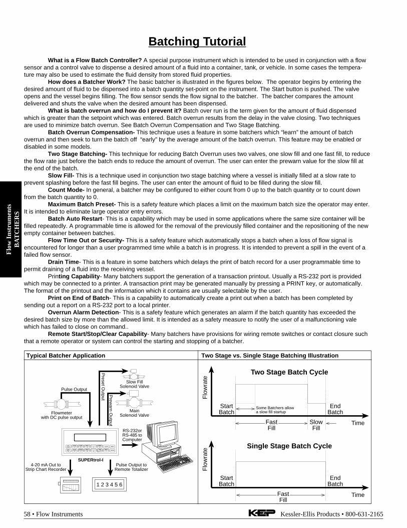
Flo
w I
nstr
umen
tsB
AT
CH
ER
S
58 • Flow Instruments Kessler-Ellis Products • 800-631-2165
Batching TutorialWhat is a Flow Batch Controller? A special purpose instrument which is intended to be used in conjunction with a flow
sensor and a control valve to dispense a desired amount of a fluid into a container, tank, or vehicle. In some cases the tempera-ture may also be used to estimate the fluid density from stored fluid properties.
How does a Batcher Work? The basic batcher is illustrated in the figures below. The operator begins by entering thedesired amount of fluid to be dispensed into a batch quantity set-point on the instrument. The Start button is pushed. The valveopens and the vessel begins filling. The flow sensor sends the flow signal to the batcher. The batcher compares the amountdelivered and shuts the valve when the desired amount has been dispensed.
What is batch overrun and how do I prevent it? Batch over run is the term given for the amount of fluid dispensedwhich is greater than the setpoint which was entered. Batch overrun results from the delay in the valve closing. Two techniquesare used to minimize batch overrun. See Batch Overrun Compensation and Two Stage Batching.
Batch Overrun Compensation- This technique uses a feature in some batchers which “learn” the amount of batchoverrun and then seek to turn the batch off “early” by the average amount of the batch overrun. This feature may be enabled ordisabled in some models.
Two Stage Batching- This technique for reducing Batch Overrun uses two valves, one slow fill and one fast fill, to reducethe flow rate just before the batch ends to reduce the amount of overrun. The user can enter the prewarn value for the slow fill atthe end of the batch.
Slow Fill- This is a technique used in conjunction two stage batching where a vessel is initially filled at a slow rate toprevent splashing before the fast fill begins. The user can enter the amount of fluid to be filled during the slow fill.
Count Mode- In general, a batcher may be configured to either count from 0 up to the batch quantity or to count downfrom the batch quantity to 0.
Maximum Batch Preset- This is a safety feature which places a limit on the maximum batch size the operator may enter.It is intended to eliminate large operator entry errors.
Batch Auto Restart- This is a capability which may be used in some applications where the same size container will befilled repeatedly. A programmable time is allowed for the removal of the previously filled container and the repositioning of the newempty container between batches.
Flow Time Out or Security- This is a safety feature which automatically stops a batch when a loss of flow signal isencountered for longer than a user programmed time while a batch is in progress. It is intended to prevent a spill in the event of afailed flow sensor.
Drain Time- This is a feature in some batchers which delays the print of batch record for a user programmable time topermit draining of a fluid into the receiving vessel.
Printing Capability- Many batchers support the generation of a transaction printout. Usually a RS-232 port is providedwhich may be connected to a printer. A transaction print may be generated manually by pressing a PRINT key, or automatically.The format of the printout and the information which it contains are usually selectable by the user.
Print on End of Batch- This is a capability to automatically create a print out when a batch has been completed bysending out a report on a RS-232 port to a local printer.
Overrun Alarm Detection- This is a safety feature which generates an alarm if the batch quantity has exceeded thedesired batch size by more than the allowed limit. It is intended as a safety measure to notify the user of a malfunctioning valewhich has failed to close on command..
Remote Start/Stop/Clear Capability- Many batchers have provisions for wiring remote switches or contact closure suchthat a remote operator or system can control the starting and stopping of a batcher.
Typical Batcher Application Two Stage vs. Single Stage Batching Illustration
Flowmeterwith DC pulse output
Pulse Output
Preset O
utput
4-20 mA Out toStrip Chart Recorder
RS-232orRS-485 toComputer
1 2 3 4 5 6
Pulse Output toRemote Totalizer
STOP
STARTPRINT
5
0 –
TIME
CLEAR
•
MENU
ENTERHELP
4PRE 1
3RATE
2TOTAL
1
GRAND6
SCROLL7
PRE 28 9
SUPERtrol-I
MainSolenoid Valve
Prew
arn Output
Slow FillSolenoid Valve
Flo
wra
te
Time
StartBatch
EndBatch
Some Batchers allowa slow fill startup
SlowFill
FastFill
Flo
wra
te
Time
StartBatch
EndBatch
FastFill
Two Stage Batch Cycle
Single Stage Batch Cycle

Flow
Instruments
BA
TC
HE
RS
Kessler-Ellis Products • 800-631-2165 Flow Instruments • 59
Low Cost, Pulse InputBatch ControllerMB2 (MINI-Batcher)
Features
• 5 Digit Scaling Factor
• Display Rate, Batch Size and(Batch Total or Grand Total)
• Second B Relay Programmable for Output atPrewarn or selected Batch/Grand Total
• Pulse Input - 10 kHz Max.
• Security Lockout
• RS422/RS232 Serial Communication Option
• Modbus RTU RS422/RS485/RS232
• NEMA 4X / IP65 Front Panel
Application:This miniature batcher is ideal for all batching applications. Thedisplay will show Batch Amount, Rate and Batch/Grand Total atthe push of a button. The Start and Stop buttons make batchingsimple.
Description:The MINI-Batcher is a 6 digit totalizer and 4.5 digit ratemeter withtwo relay outputs. One output is dedicated to the batch amount(Preset A), the other can be activated for Prewarn or Batch/GrandTotal. The unit can count up to the preset (reset to 0) or down fromthe preset (set to preset). Start, Stop and Reset functions can beactivated from the front panel or remote inputs.An analog output (assignable for Rate or Batch Amount) is avail-able for data logging.Several units can communicate to a host computer on a singleRS232 or RS422 loop.
Specifications:Display: 6 digit, 0.55" High LEDInput Power:
110 VAC ± 15% or 12 to 15 VDC220 VAC ± 15% or 12 to 15 VDC24 VAC ± 15% or 12 to 15 VDC
Current: 250 mA DC max. or 6.5 VA ACOutput Power: (AC powered units only)+12 VDC @ 50 mA, unregulated -10 + 50%Temperature:Operating:
+32°F (0°C) to +130°F (+54°C)Storage:
-40°F (-40°C) to +200°F (93°C)Humidity: 0-90% NoncondensingMemory: EEPROM stores data for 10 years if power is lost.Listing: CSA (File No. LR91109), CE Compliant,
NRTL/C pending
Inputs:3: High Impedance DC pulse input 4-30 VDC (high), Open or
0-1 VDC (low), 10 kΩ impedance, 10 kHz max. speed.3M: Mag. Input, accepts 30mV input (50 V max.) signals 10 KΩ
imp. 5 kHz max.Stop / Reset:Front Panel:
STOP/RST button stops batch if batch is running, Resets dis-played value and control output if batch is stopped.
Remote:4-30 VDC, positive edge: stops batch if batch is running, Re-sets batch amount if batch is stopped.
NOTE: Hold either front or remote reset active to inhibit any startinputs.
Scaling Factor (K-Factor): A user programmable K-Factor isused to convert the input pulses to engineering units. The 5 digitK-Factor divider, with decimal keyed into any position, allowseasy direct entry of any K-Factor from 0.0001 to 99999.Presets: Two control outputs are provided. A 5 digit value canbe entered for both presets. The decimal point location is thesame as the counter (No decimal in Batch Total counter).PRESET A:
The preset A output is dedicated to the batch amount. WhenSTART is activated, Relay A will energize and remain on untilthe batch is complete or the batch is stopped.
PRESET B:The preset B output can be programmed to activate as aPrewarn (for two stage batch control) or activate on BatchTotal or Grand Total (selectable).When set for PREWARN, Relay B will energize when STARTis activated and drop out at Prewarn number before preset.When set for Batch Total or Grand Total, Relay B will activatewhen the batch total or grand total counts up to preset Bamount. The output ON time can be set for a duration (0.01to 99.99 sec.) or latched (0.00 setting). If a value other than0.00 is set for the duration, the batch total or grand total willauto-reset at preset B.
• 30mV Magnetic Pickup Input Option
• 4-20mA or 0-20mA Analog Output Option

Flo
w I
nstr
umen
tsB
AT
CH
ER
S
60 • Flow Instruments Kessler-Ellis Products • 800-631-2165
Wiring:1- COMMON
2- N.O.(N.C./NPN)
3- COMMON
4- N.O.(N.C./NPN)
5- COUNT
6- START
7- 12VDC OUT/+DC IN
8- -DC (GROUND)
9- STOP/RESET
10- NOT USED
11- A.C. INPUT
12- A.C. INPUT
RE
LA
YS
AB
13- V+
14- I SINK
AN
AL
OG
OU
TP
UT
ONCAL.
0-20mACOUNT
SET
OFFRUN
4-20mARATERUN1
2
3
4
ON
SW
ITC
H
Control Outputs:Relays:
2 each N.O. Relay; 5 Amps 120/240 VAC or 28 VDC. (N.C.relay contacts and NPN transistor output available with solderjumpers.
Analog Output:An optional 4-20mA (0-20mA) output is available for the Mini-Batch series. The output can be programmed to track rate orbatch amount. Connections are via a 2 terminal pluggablescrew connector. Programming is accomplished by using thefront panel in conjunction with rear dip switches. Accuracy:±.25% FS worst case. Compliance Voltage: 3 to 30 VDC noninductive.
Lockout: Unauthorized front panel changes can be preventedby entering a user selected 5 digit code. The front panel can becompletely locked out (except Start & Stop) or the preset canremain accessible.Ratemeter: Accuracy: 0.01% FS (±1 display digit).The rate display updates once per second. The rate meter canbe programmed to sample from 2 to 24 seconds maximum, andauto-range up to 5 digits of significant information. The ratemeterdisplays in units per second, minute or hour.Batch or Grand Totalizer: In addition to viewing the batchamount, a second counter can be viewed. This counter is pro-
Dimensions:
grammable to count either the number of batches (Batch Total)or the grand total count (Grand Total).RS232/RS422 with KEP Protocol:If the serial interface option is supplied, up to 99 units can belinked together. (The terminal addressing the unit must be ca-pable of driving all loads in the loop.) Unit status and new setpoints can be communicated by serial communication. Modechanges, however, must always be made on the front panel.Data is received and transmitted over standard EIA RS232 orRS422 levels. Unit number, baud rate and parity are entered inthe “Program Setting” set up mode and remain in memory even ifpower is off.RS232/RS422/RS485 with Modbus RTU Protocol:The serial port can be used for serial printing or also for dataacquisition. The unit can address up to 247 units (The terminaladdressing the unit must be capable of driving all loads in theloop.) The unit can communicate with a master device through aModbus-RTU protocol. The data given for each parameter is inIEEE float format comprising of 2 words. The unit can beconnected in a network.
Device ID: 01-247Baud Rates: 300, 600, 1200, 2400, 4800, 9600Parity: None, Odd, EvenProtocol: Modbus RTU (Half Duplex)
3.925(99.7)
4.437(112.7)
2.625(66.68)
3.622(92)
1.772(45)
CUSTOMER PANELPanel Thickness 0.062" (1.5)to 0.187" (4.7) max.
0.587(14.91)
4.245(107.8)
BEZELGASKET
Ordering InformationExample: MB2 A 3 1Series:
MB2= MiniBatcherOperating Voltage:
A= 110 VAC ± 15% or 12 to 15 VDCB= 220 VAC ± 15% or 12 to 15 VDCC= 24 VAC ± 15% or 12 to 15 VDC
Count Inputs:3 = Standard, 4-30 VDC pulse inputs.3M = Mag. Input, 30mV input
Options1= RS232 Communications2= RS422 Communications3= Modbus RTU RS2324= Modbus RTU RS422/RS485A= Analog Output (4-20/0-20 mA)CE = CE Compliant Version
AccessoriesXHV - Explosion proof housing (see accessories section)NEMA-1/8DIN- NEMA 4X enclosure (see accessories section)P1000- Serial Printer (see accessories section)Separate non keyboard panel order #34235Separate keyboard panel - order #34569

Flow
Instruments
BA
TC
HE
RS
Kessler-Ellis Products • 800-631-2165 Flow Instruments • 61
Features• "EZ Setup" Guided Setup for First Time Users
• Rate/Total and Batching Functions
• Menu Selectable Hardware & Software Features
• Environmental Compliance Monitoring and ReportGeneration
• Universal Viscosity Curve (UVC) and API Eq.
• Advanced Batching Features: Overrun Compen-sation, Autobatch Start, Print End of Batch, SlowFill, 2 Stage Batching
• Isolated Outputs Standard
• RS-232 Port Standard, RS-485 OptionalAdvanced Printing CapabilitiesWindows™ Setup Software
• DIN Enclosure with Two Piece Connectors
• On Board Data Logging
• DDE Server & HMI Software Available
• Enhanced Modem Features for Remote Metering
• NEW! - Attractive Wall Mount Enclosure
Multi-Function Flow Totalizer,Ratemeter and BatcherSUPERtrol-I
Specifications:Flow Meters and Computations
Meter Types: All linear and square law meters supportedincluding: vortex, turbine, magnetic, PD, target, orifice, venturi,v-cone and many othersLinearization: Square root, 16 point table or UVC tableComputations: Volume, Corrected Volume & MassFluid Computations: Temperature, Density, Viscosity andAPI 2540 for petroleum.
EnvironmentalOperating Temperature: 0°C to +50°CStorage Temperature: -40°C to +85 CHumidity : 0-95% Non-condensingMaterials: U.L. approved
Listing: UL/C-UL Listed (File No. E192404), CE Compliant
DisplayType: 2 lines of 20 charactersTypes: Backlit LCD and VFD ordering optionsCharacter Size: 0.3" nominalUser programmable label descriptors and units of measure
KeypadKeypad Type: Membrane Keypad with 16 keys
EnclosureSize: See DimensionsDepth behind panel: 6.5" including mating connectorType: DINMaterials: Plastic, UL94V-0, Flame retardantBezel: Textured per matt finish
Real Time ClockThe SUPERtrol-I is equipped with a battery backed real timeclock with display of time and date.Format:
12 or 24 hour time displayDay, Month, Year date display
Power InputThe factory equipped power option is internally fused. Aninternal line to line filter capacitor and MOV are provided foradded transient suppression.
110 VAC Power: 85 to 127 Vrms, 50/60 Hz (11.0 VA)220 VAC Power: 170 to 276 Vrms, 50/60 Hz (11.0 VA)DC Power:
12 VDC (10 to 14 VDC); 300 mA max.24 VDC (14 to 28 VDC); 300 mA max.
Trend, Alarm and Log
your SUPERtrol Data with
KEPware HMI Software!
See Special Flow Instruments Section
Description:The SUPERtrol-I Flow Computer satisfies the instrumentrequirements for a variety of flowmeter types in liquid applications.Multiple flow equations and instrument functions are available ina single unit with many advanced features.
The alphanumeric display shows measured and calculatedparameters in easy to understand format. Single key directaccess to measurements and display scrolling is supported
The versatility of the SUPERtrol-I permits a wide measure ofversatility within the instrument package. The various hardwareinputs and outputs can be “soft” assigned to meet a variety ofcommon application needs. The user “soft selects” the usage ofeach input/output while configuring the instrument.
The isolated analog output can be chosen to follow volume flow,corrected volume flow, mass flow, temperature, or density bymeans of a menu selection. Most hardware features areassignable by this method.
The user can assign the standard RS-232 Serial Port for datalogging, transaction printing, or for connection to a modem forremote meter reading.
A Service or Test mode is provided to assist the user duringstart-up system check out by monitoring inputs and exercisingoutputs and printing system setup.

Flo
w I
nstr
umen
tsB
AT
CH
ER
S
62 • Flow Instruments Kessler-Ellis Products • 800-631-2165
Flow Inputs:Analog Input:Accuracy: 0.01% FS at 20° C
RangesVoltage: 0-10 VDC, 0-5 VDC, 1-5 VDCCurrent: 4-20 mA, 0-20 mA
Basic Measurement Resolution:16 bit
Update Rate: 4 updates/secAutomatic Fault detection: Signal over/under-range,
Current Loop BrokenCalibration: Software Calibration (no trimmers) and
Auto-zero ContinuouslyExtended calibration:
Learns Zero and Full Scale of each range usingspecial test mode.
Fault Protection:Reverse Polarity: No ill effectsOver-Voltage Limit: 50 VDC Over voltage
protectionOver-Current Protection: Internally current limited
protected to 24VDCPulse Inputs:
Number of Flow Inputs: one with or without quadratureInput Impedance: 10 KΩ nominalPullup Resistance: 10 KΩ to 5 VDC (menu selectable)Pull Down Resistance: 10 KΩ to commonTrigger Level: (menu selectable)
High Level InputLogic On: 3 to 30 VDCLogic Off: 0 to 1 VDC
Low Level Input (mag pickup)Sensitivity:
10 mV or 100 mVMinimum Count Speed:
Menu selectableMaximum Count Speed:
Menu Selectable: 40Hz, 3000Hz or 20 kHzOvervoltage Protection: 50 VDC
Auxiliary / Compensation InputThe auxiliary/compensation input is menu selectable fortemperature, density or not used. This input is used forthe compensated input when performing compensatedflow calculations. It can also be used as a generalpurpose input for display and alarming.
Operation: RatiometricAccuracy: 0.01% FS at 20° CBasic Measurement Resolution:
16 bitUpdate Rate: 1 update/sec minimumAutomatic Fault detection:
Signal Over-range/under-rangeCurrent Loop BrokenRTD shortRTD openFault mode to user defined default settings
Fault Protection:Reverse Polarity: No ill effectsOver-Voltage Limit (Voltage Input): 50 VDC
Available Input RangesVoltage:0-10 VDC, 0-5 VDC, 1-5 VDCCurrent: 4-20 mA, 0-20 mAResistance: 100 Ohms DIN RTD
100 Ohm DIN RTD(DIN 43-760, BS 1904):
Three Wire Lead CompensationInternal RTD linearization learns ice point resistance1 mA Excitation current with reverse polarityprotectionTemperature Resolution: 0.01 C
Control InputsSwitch Inputs are menu selectable for Start, Stop, Reset,Lock, Inhibit, Alarm Acknowledge, Print or Not Used.
Control Input SpecificationsInput Scan Rate: 10 scans per secondLogic 1: 4 - 30 VDCLogic 0: 0 - 0.8 VDCInput Impedance: 100 KΩControl Activation:
Positive Edge or Pos. Level based on productdefinition for switch usage.
Excitation VoltageMenu Selectable: 5, 12 or 24 VDC @ 100 mA (faultprotected)
Relay OutputsThe relay outputs are menu assignable to (Individuallyfor each relay) Low Rate Alarm, Hi Rate Alarm, PrewarnAlarm, Preset Alarm or General purpose warning(security), low temperature/high temperature.
Number of relays: 2 (4 optional)Contact Style: Form C contactsContact Ratings: 5 amp, 240 VAC or 30 VDC
Serial CommunicationThe serial port can be used for printing, datalogging,modem connection and communication with a computer.RS-232:
Device ID: 01-99Baud Rates: 300, 600, 1200, 2400, 4800, 9600,
19200Parity: None, Odd, EvenHandshaking: None, Software, Hardware
Print Setup: Configurable print list and formatting.Print Out: Custom form length, print headers,
print list.Print Initialization: Print on end of batch, key
depression, interval, time of day orremote request.
RS-485:Device ID: 01-247Baud Rates: 300, 600, 1200, 2400, 4800, 9600,
19200Parity: None, Odd, EvenProtocol: Modbus RTU (Half Duplex)
Data LoggingThe data logger captures print list information to internalstorage for aproximately 1000 transactions. Thisinformation can be used for later uploading or printing.Storage format is selectable for Comma-Carriage Returnor Printer formats.

Flow
Instruments
BA
TC
HE
RS
Kessler-Ellis Products • 800-631-2165 Flow Instruments • 63
Terminal Designations
13P
ULS
E O
UT
PU
T +
PU
LSE
OU
TP
UT
-
AN
ALO
G O
UT
PU
T -
AN
ALO
G O
UT
PU
T +
RLY
1
RLY
2
AC
LIN
EA
C L
INE
2418C
OM
19 20 21 22 23
NO
NC
CO
MN
O
14 15 16 17N
C
PO
WE
R IN
DC
-
4-20
mA
CO
M R
LY3
CO
M R
LY4
26 27 28 29 30
NO
NC
NO
DC
+25N
C
PU
LSE
IN 1
PU
LSE
IN 2
DC
OU
TP
UT
CO
MM
ON
RT
D E
XC
IT +
RT
D S
EN
SR
TD
SE
NS
-
CN
TR
IN 1
CN
TR
IN 2
CN
TR
IN 3
CO
MM
ON
----
----
-
8 9 10 11 122 3 4 5 6 71
SE
E U
SE
RM
AN
UA
L
CO
MP
Iin +
+
Vin
+Iin
+
Vin
+
IN IN
FLO
W
Isolated Analog OutputThe analog output is menu assignable to correspond to theUncompensated Volume Rate, Corrected Volume Rate, MassRate, Temperature, Density, Volume Total, Corrected VolumeTotal or Mass Total.Type: Isolated Current SourcingAvailable Ranges: 4-20 mA, 0-20 mAResolution: 12 bitAccuracy: 0.05% FS at 20° CUpdate Rate: 1 update/sec minimumTemperature Drift: Less than 200 ppm/CMaximum Load: 1000 ohms (at nominal line voltage)Compliance Effect: Less than .05% Span60 Hz rejection: 40 dB minimumCalibration: Operator assisted Learn ModeAveraging: User entry of damping constant to cause a
smooth control action
Isolated Pulse outputThe isolated pulse output is menu assignable toUncompensated Volume Total, Compensated Volume Totalor Mass TotalPulse Output Form: Open CollectorMaximum On Current: 25 mAMaximum Off Voltage: 30 VDCSaturation Voltage: 1.0 VDCMaximum Off Current: 0.1 mAPulse Duration: 10 mSec or 100 mSec(user selectable)Pulse output buffer: 256Fault Protection
Reverse polarity: Shunt Diode
Standard Dimensions5.67 (144)
2.83(72)
6.15 (156) 0.5(13)
0.28 (7.2)
3.43(87)
6.18 (157)
Dotted Line Shows Optional Bezel Kit
PanelCutout
5.43(138)
2.68(68)
Dimensions are in inches (mm)
0.4 (10)
STOP
STARTPRINT
5
0 –
TIME
CLEAR
•
MENU
ENTERHELP
TEMP4
PRE 13
RATE2
TOTAL1
GRAND6
SCROLL7
PRE 28
DENS9
RATETOTAL 267395.749
GPMGAL
147.43
Wall Mount Dimensions7.64 (194)
6.34
(16
1)
2.15
(54.
5)
2.32(59)
0.4(10) 1.06
(27)1.10(28)
1.16(29.5)
0.75(19)
1.10(28)
1.10(28)
5.95 (151)
0.63(16)
0.55(14)
1.14(29)
4.72
(12
0)
MENU
ENTER
TOTAL RATE
1 2
6 7
GRAND SCROLL
ALARM 1 TEMP
3 4
8 9
PRESALARM 2
PRINTCLEAR
5
0 - .
TIME HELP
4.8 (122)
0.75” Conduit Knockouts(3 places)
Ordering InformationExample ST1 L 1 A 0 P TBSeries:
ST1= Supertrol-1Display Type:
L= LCDV= VFD
Input Type:1= 110 VAC2= 220 VAC3= 12 VDC (10 to 14 VDC)4= 24 VDC (14 to 28 VDC)
Relays:A= 2 SPDT RelaysB= 4 SPDT RelaysC= 2 Form A Solid State Relays
Network Card:0= None (STD)2= RS485/Modbus (available soon)
Mounting:P= Panel MountN= NEMA 4 Wall MountW= NEMA 12/13 Wall Mount w/ Clear CoverE= Explosion Proof (No Button Access)X= Explosion Proof (with Button Access)
Options:TB= RS485 Terminal Block for Panel Mount Enclosure
Accessories:KEPS-KEP1-32 = KEP RS232 for SUPERtrol 1, SUPERtrol 1LE,
SUPERtrol 2 and LEVELtrol 2 • 32 Bit DDE ServerP1000 Printer (see Accessories)IM-2400 = Internal Modem for SUPERtrol FamilyMPP2400 = Port Powered ModemMPP2400N = Port Powered Modem in NEMA4 enclosure

Flo
w I
nstr
umen
tsB
AT
CH
ER
S
64 • Flow Instruments Kessler-Ellis Products • 800-631-2165
Features
• Start/Stop Buttons & Remote Inputs
• Separate 8 Digit K-Factors For Rate & Total
• Accepts Pulse or Analog Inputs
• Displays Rate, Total and Grand Total
• Security Lockout with Missing Pulse Detection
• Scaled Pulse Output
• Two Way RS232/422 Communications Option
• 2 Setpoints For Two Stage Valve Control
• NEMA 4X (IP65) Front Panel
BATCHtrol II Batch Controller With Two StageValve Control
Description:Featuring 8 digits of bright, .55 inch, alpha-numeric display, theBATCHtrol II can accept up to 20,000 pulses per second of digitalcount. The analog input versions accept inputs, such as 4 to 20 mAor 1 to 5V. The standard unit has two separate, 8 digit, floatingdecimal, "K" factors to convert the inputs to meaningful total andrate data. An optional 16 point K-factor can linearize flow from non-linear meter outputs. The user, with the push of a button, cantoggle back and forth to view the total of the batch, the rate of flowor the grand total of flow.The BATCHtrol II may be thought of as two separate counters anda ratemeter. The "batching" counter counts to prewarn and presetnumbers entered by the user and enables separate control outputs.The "totalizing" counter gives a cumulative reading or grand total.Finally, the ratemeter counts the number of pulses per second and,with its scaling feature, can provide gallons per minute or any otherrate measurement without the totalizer losing counts. At any time,the user may view the total, the grand total or the rate while neverinterrupting the counting process.Setup is done through the front panel and the menu drivensoftware in the unit. Start-Stop control can be activated via thefront panel buttons or remote inputs.The unit operates from either 110 VAC/12 to 27 VDC, or optional220 VAC/12 to 27 VDC. If AC power is used, two built-in regulated12 VDC @ 100 mA power supplies are offered. They can beconnected to provide +12 VDC and-12VDC or +24 VDC to drive external devices. CMOS Logic isused to provide high noise immunity and low power consumptionwith EEPROM to hold data a minimum of 10 years if power isinterrupted.Up to 15 units can be connected to optional RS232 or RS422communications port to set control points or access data.
Specifications:DISPLAY:8 Digit, .55" High, 15 Segment, Red Orange, LED.INPUT POWER: (Internally Fused)A: 110 VAC ±15% or 12 to 27 VDCB: 220 VAC ±15% or 12 to 27 VDCCURRENT:Maximum 280 mA DC or 5.3 VA at rated AC voltage.OUTPUT POWER: (On AC powered units only):+12 VDC at 100mA. Separate Isolated 12 VDC at 100mA toallow +12 VDC or +24 VDC regulated ±5% worst case.DC Outputs are supplied with resettable fuses.
TEMPERATURE:Operating: +32°F (0°C) to +130°F (+54°C).Storage: -40°F (-40°C) to +200°F (+93°C).ET: Extended Temperature -40° to 158°F (-40° to 70° C)
ET not available with analog inputs or outputsHUMIDITY: 0-90% NoncondensingListing: CE CompliantMEMORY:EEPROM stores all program and total data for minimum of 10years if power is lost.PULSE INPUTS:3A: Standard, High impedance pulse input.Low: Open or 0 to 1 VDCHigh: 3 to 30 VDC, 10K Ohm impedance 20 kHz max. inputspeed (min. on/off 25 µsec.).3B: Same as 3A but has 4.7K Ohm input pull up resistors to +5VDC on input for pulsing with contact to ground or NPN opencollector transistor.ANALOG INPUTS:The current loop or voltage input is converted to a highly linear 0to 10 kHz frequency. This frequency can then be scaled by the 8digit K-Factors to total or display rate in separate engineeringunits.Accuracy over full temperature range:Zero error: +0.175% full scale max.Overall error: +0.5% full scale max.5A/7A: 4-20mA, 250 Ohm impedance5B/7B: 0-20mA, 250 Ohm impedance5C/7C: 1-5 VDC, 15K Ohm impedance5D/7D: 0-5 VDC, 15K Ohm impedance5E/7E: 0-10 VDC, 15K Ohm impedance6A: 4-20 mA, Square Law, 250 Ohm impedanceRESET:Front push button: “CLR” resets displayed number and controloutput.REMOTE START & STOP/RESET INPUTS:A 4 to 30VDC positive pulse will activate these inputs. Pin 10 isthe START input and when activated, the unit will "start." Pin 5 isthe STOP/RESET input. When activated, the unit will "stop" (ifunit is started and the batch is not complete). When the unit isstopped or the batch is complete, activating this input will resetthe total. If pin 5 is held high (4 to 30VDC), the display will flash"STOPPED" and any start inputs will be inhibited. Stop alwaysover-rides Start input.NOTE: The remote START input will not work with the type
7 input option (analog in & analog out) boards. Allother features will work as described above.
These new features have not yet been added to the 16 pointlinearization BATCHtrol II version 12.0 .

Flow
Instruments
BA
TC
HE
RS
Kessler-Ellis Products • 800-631-2165 Flow Instruments • 65
FACTORED OUTPUT:The BATCHtrol II gives one pulse out for each factored totalcount. Open collector sinks 30 VDC maximum to 1 volt maximumat 100mA maximum. Output speed is user selectable (see tablebelow). An internal buffer holds up to 10,000 pulses for outputat the selected frequency before “DATALOST” flashes, indicatingpulses are lost. If factored rate exceeds 7 digits “RFF…” flashes.These alarms indicated that speed has been exceeded.
Speed(HZ) 10 200 2000 20000Min. on/off(msec) 47.5 2.0 0.2 0.013
CONTROL OUTPUTS:(Each of two outputs)1. NPN Transistor Version: (Optional)The open collector sinks max. 250mA from 30 VDC when active.(When relay is used, 10 VDC is provided at transistor outputsthrough relay coil. If greater than 2mA is used, relay will remainenergized. Applying greater than 10 VDC may destroy unit.Transistor will sink 100mA in “ON” state).2. SPDT Relay Version:10A 120/240 VAC or 28 VDC (Standard).ANALOG OUTPUT:Digital input or analog input (except Square Law) versions canbe ordered with an analog output of the rate or total reading.User keys in the low and high settings at set-up.Current Outputs:A sinking driver generates a corresponding linear current throughthe external devices, updating with each update of the rate.Accuracy is ±.5% FS worst case. Compliance voltage must be3 to 24 VDC, non inductive. (The BATCHtrol II can provide theDC source as long as the drop across all devices being drivendoes not exceed 21 V).Voltage Outputs:When the voltage out option is ordered, a controlled voltageoutput is located at terminal 3 and referenced to pin 12 (ground).Accuracy is .1% @ 20°C( max. drift .01%/C°).SECURITY:The BATCHtrol II has a missing pulse detector. The user selectsthe amount of time (1 to 99 sec.) that the unit will "wait" for inputpulses. If the unit doesn't receive pulses within the selectedtime, the unit displays "SECURITY" and both relays drop out.(00 Disables the security feature; Entering the lockout codereturns the unit to the run mode)PRESETS:The user may enter two numbers to set up the batch totalizer,Preset and Prewarn. The Prewarn is a number set a certainnumber of counts before the preset number. For instance, youmay want one hundred gallons in a particular batch. You mayalso want a valve to close and slow down flow 25 gallons beforethe end. Your preset is 100, your prewarn is 25. When the startis activated, the relays energize simultaneously to start flow.When the totalizer reaches 75, the prewarn relay drops out.When the totalizer reaches 100 the preset relay drops out. Thepreset values can be viewed or changed via the menu (whenstopped).K-FACTOR:In the standard unit a fixed K-Factor is used to convert the inputpulses or frequency generated internally by the analog input toengineering units. The 8 digit K-Factor dividers, with decimalkeyed into any position, allow easy direct entry of any K-Factorgreater than 0.0001 to 99999999. Separate K-Factors may beentered for the total and rate section. Thus, you may batch andtotal in gallons and display rate in liters per hour. The maximumfactored count speed is 20,000 Hz. The maximum factored rateis 7 digits.16 POINT LINEARIZATION:This variable K-factor option makes flow systems more accurateand often extends their usable range by allowing users to dial indifferent K-factors for different flow rates. It works with eitherpulse input or standard analog current loop or voltage input. Itis recommended for flow meters whose K-factors change with
different rates of flow. From 3 to 16 points of frequency from 0 to10,000 Hz. and K-factors greater than .0001 to 999,999 aredialed in at set up. The 16 point linearization option uses 8 digitfloating math to interpolate between settings. Rate per second,per minute or per hour programmability eliminates the need tocalculate separate K-factors for total and rate.TOTALIZER:Each of the total and grand total counters have 8 digits. In theset-up mode choose “R0” (reset to zero) for adding operation or“SP” (set to preset) for subtracting operation. While viewing thetotal the display can be made to flash the grand total by pressing“ENT”. Activating “CLR” while the grand total is flashing, resetsthe grand total counter.RATEMETER:Accurate to 51/2 digits (+1 display digit). The rate meter can beprogrammed to accept almost any number of pulses per unit ofmeasurement, sample from 2 to 24 seconds maximum, andautorange up to 6 digits of significant information. The ratemeter with a “K” factor of 1 displays the rate of pulses persecond. Simply dial in the proper “K” factor to display in minutes,hours or other units of measurement. (See 16 Point Opt. Above)Press the “C” button while the unit is displaying the batch todisplay the rate; “R” is displayed on the left side of the display.WEIGHT:This feature is used to provide a weighted averaging of the ratedata being received. Higher settings provide more averaging fora more stable display, derived from the equation:
(Old Data x "Weight") + New Data("Weight" +1)
LOCKOUT:Unauthorized front panel changes can be prevented by enteringa user selected four digit code.OUTCARD:RS232 or RS422 serial two way communication options areavailable. Up to 15 units can be linked together and addressedseparately to transmit unit status or accept new set points in thestandard ASCII format. Baud rates of 300, 600,1200,2400 4800or 9600 as well as choice of odd, even, space or mark parity canbe selected by keypad control.
Termination:
1 • NOT USED 2 • SCALED OUTPUT (OPEN COLLECTOR) 3 • ANALOG OUTPUT (SINK) 4 • INPUT (PULSE/ANALOG) 5 • STOP / RESET INPUT 6 • NOT USED 7 • NOT USED 8 • NOT USED 9 • NOT USED10 • START INPUT11 • NO CONNECTION12 • GROUND (-DC)13 • 12 VOLTS OUT14 • + DC POWER IN (12 to 27 VDC)15 • ISOLATED -12 VOLTS OUT16 • ISOLATED +12 VOLTS OUT17 • AC INPUT18 • AC INPUT19 • PREWARN TRANSISTOR20 • PRESET TRANSISTOR
1 • N.O. 2 • N.C. PRESET 3 • COMMON 4 • N.O. 5 • N.C. PREWARN 6 • COMMON
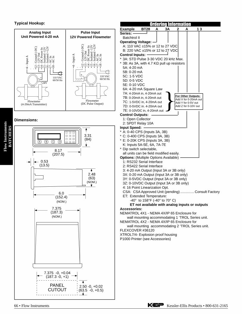
Flo
w I
nstr
umen
tsB
AT
CH
ER
S
66 • Flow Instruments Kessler-Ellis Products • 800-631-2165
Dimensions:
0.53(13.5)
6.0(152.4)
2.48(63)
(NOM.)
(NOM.)
7.375(187.3) (NOM.)
PANELCUTOUT
2.50 -0, +0.02(63.5 -0, +0.5)
7.375 -0, +0.04(187.3 -0, +1)
A B C D
1 2 3
4 5 6
7 8 9
CLR 0 SET
8.17(207.5)
3.31(84)
Flowmeter(4-20mA Transmitter)
•4 -
Inp
ut A
. . •12
- G
roun
d (-
DC
)•1
3 -
12V
Out
•14
- D
C P
ower
In
•15
- Is
olat
ed -
12V
•16
- Is
olat
ed +
12V
•17
- AC
In
•18
- AC
In
110 VAC60/50 Hz
+24V
-
Typical Hookup:
Flowmeter(DC Pulse Output)
•4 -
Inp
ut A
. . •12
- G
roun
d (-
DC
)•1
3 -
12V
Out
•14
- D
C P
ower
In
•15
- Is
olat
ed -
12V
•16
- Is
olat
ed +
12V
•17
- AC
In
•18
- AC
In
110 VAC60/50 Hz
+-
Pulse Input12V Powered Flowmeter
Analog InputUnit Powered 4-20 mA
Ordering InformationExample BT28 A 3A 2 A 1 3Series:
Batchtrol IIOperating Voltage:
A: 110 VAC ±15% or 12 to 27 VDCB: 220 VAC ±15% or 12 to 27 VDC
Control Inputs:* 3A: STD Pulse 3-30 VDC 20 kHz Max.* 3B: As 3A, with 4.7 KΩ pull up resistors
5A: 4-20 mA5B: 0-20 mA5C: 1-5 VDC5D: 0-5 VDC5E: 0-10 VDC6A: 4-20 mA Square Law7A: 4-20mA in, 4-20mA out7B: 0-20mA in, 4-20mA out7C: 1-5VDC in, 4-20mA out7D: 0-5VDC in. 4-20mA out7E: 0-10VDC in, 4-20mA out
Control Outputs:1: Open Collector2: SPDT Relay 10A
Input Speed:* A: 0-40 CPS (Inputs 3A, 3B)* C: 0-400 CPS (Inputs 3A, 3B)* E: 0-20K CPS (Inputs 3A, 3B)
K: Inputs 5A-5E, 6A, 7A-7E* Dip switch selectable,
all units can be field modified easily.Options: (Multiple Options Available)
1: RS232 Serial Interface2: RS422 Serial Interface3: 4-20 mA Output (Input 3A or 3B only)3X: 0-20 mA Output (Input 3A or 3B only)3Y: 0-5VDC Output (Input 3A or 3B only)3Z: 0-10VDC Output (Input 3A or 3B only)4: 16 Point Linearization Opt.CSA: CSA Approved Unit (pending) .............. Consult FactoryET: Extended Temperature:
-40° to 158°F (-40° to 70° C)ET not available with analog inputs or outputs
Accessories:NEMATROL 4X1 - NEMA 4X/IP 65 Enclosure for
wall mounting accommodating 1 ‘TROL Series unit.NEMATROL 4X2 - NEMA 4X/IP 65 Enclosure for
wall mounting accommodating 2 ‘TROL Series unit.FLEXCOVER #36120XTROL7/4- Explosion proof housingP1000 Printer (see Accessories)
For Other Outputs:Add X for 0-20mA outAdd Y for 0-5V outAdd Z for 0-10V out

Flow
Instruments
FL
OW
CO
MP
UT
ER
S
Kessler-Ellis Products • 800-631-2165 Flow Instruments • 67
Flow Computer TutorialWhat is a flow computer? A special purpose device which computes a corrected flow based on information derived from
raw input signals and stored sensor and fluid properties informationWhat are the typical applications requiring a flow computer? Computation of Heat Flow, Mass Flow, Corrected
Volume Flow typically require a flow computer. In addition, many flow sensors require linearization to improve accuracy. The flowcomputer is also used for data logging, communication, remote metering, alarming and control functions. In many cases a flowcomputer may replace some of the functionality of a small PLC in your application.
What are typical uses of flow computers? The figures and equations below illustrate a number of the common applica-tions for flow computers.
Where do the equations come from which are solved by the flow computer? All flow measurement sensors havebasic mathematical expressions which describe how they relate the measured input signal to a flow measurement. Often there area number of such expressions for each flowmeter type which range from the simple to those which include additional second ordereffects. In addition, there are basic equations from thermodynamics and industry standard equations which are utilized in liquid,gas, steam, and heat.
How can you enhance the accuracy of flow meters? A flow computer often offers a variety of performance enhance-ment functions. These range from simple square root functions, to more elaborate linearization tables applicable to that flowmetertype. In addition, the flow computer can correct for changes in physical dimensions of the flowmeter with temperature and for theeffects of changes in fluid properties of the material being measured in some cases.
How are fluid properties determined? Fluid properties are stored within the flow computer. Properties are then com-puted as a function of measured fluid temperature and/or pressure. Density and viscosity are among the most commonly com-puted fluid properties.
What types of flowmeters typically use flow computers? The most common types used in conjunction with flowcomputers are turbine, vortex, positive displacement, orifice and similar types, magnetic flowmeters, and a variety of specialflowmeter types. Flow computers are often used with other types when the application calls for local information display, datacommunications, control, alarm, and data logging functions.
What other factors should be considered? Flexibility in use of flow computation and use of inputs and outputs, signalinput resolution and accuracy, isolation, 24VDC to power transmitters, networking, communications software and accessories,printing, data logging and remote metering support. Approvals may also be required. Instrument setup software is also of value.Application support from the manufacturer is also important.
Steam Mass & Steam HeatIllustration
TemperatureTransmitter
PRINT5
0 –
TIME
CLEAR
•
MENU
ENTERHELP
TEMP4
PRE 13
RATE2
TOTAL1
GRAND6
SCROLL7
PRE 28
DENS9
PressureTransmitter
Orifice Platewith DP Transmitter
CalculationsMass FlowMass Flow = volume flow • density (T, p)
Heat FlowHeat Flow = Volume flow • density (T, p) • Sp. Enthalpy of
steam (T, p)
CalculationsNet Heat FlowNet Heat Flow =
Volume flow • density (T, p) • [ED (T, p)– E
W (T
S(p))]
ED
= Specific enthalpy of steamE
w= Specific enthalpy of water
TS(p)
= Calculated condensation temperature (= satu-rated steam temperature for supply pressure)
Steam Net HeatIllustration
Flowmeter TemperatureTransmitter
PRINT5
0 –
TIME
CLEAR
•
MENU
ENTERHELP
TEMP4
PRE 13
RATE2
TOTAL1
GRAND6
SCROLL7
PRE 28
DENS9
PressureTransmitter
Water
Steam
Applications & Equations

Flo
w I
nstr
umen
tsF
LO
W C
OM
PU
TE
RS
68 • Flow Instruments Kessler-Ellis Products • 800-631-2165
CalculationsDelta Heat FlowNet Heat Flow =
Volume flow • density (p) • [ED (p)– E
W (T)]
ED
= Specific enthalpy of steamE
w= Specific enthalpy of water
Steam Delta HeatIllustration
Flowmeter
TemperatureTransmitter
PRINT5
0 –
TIME
CLEAR
•
MENU
ENTERHELP
TEMP4
PRE 13
RATE2
TOTAL1
GRAND6
SCROLL7
PRE 28
DENS9
PressureTransmitter
Water
SaturatedSteam
CalculationsCorrected Volume Flow Corrected Volume Flow =
Volume Flow • P/Pref
• Tref
/T • Zref
/Z
Combustion Heat Flow Combustion Energy =
C • ρref
• Q • P/Pref
• Tref
/T • Zref
/Z
Mass Flow Mass Flow =
Actual Volume Flow • ρref
• P/Pref
• Tref
/T • Zref
/Z
ρref
= Reference densityT
ref= Reference temperature
Pref
= Reference pressureZ
ref= Reference Z-factor
C = Specific combustion heatQ = Volume flow
GasCorrected Volume FlowCombustion Heat FlowMass FlowIllustration
Flowmeter TemperatureTransmitter
PRINT5
0 –
TIME
CLEAR
•
MENU
ENTERHELP
TEMP4
PRE 13
RATE2
TOTAL1
GRAND6
SCROLL7
PRE 28
DENS9
PressureTransmitter
CalculationsCorrected Volume Flow Corrected Volume Flow = vol. flow • (1 - α • (Tf-Tref))2
Mass FlowMass Flow =
volume flow • (1-α • (T-Tref
))2 • ref. density
Heat FlowHeat Flow =
C • volume flow • (1-α • (T-Tref
))2 • ref. density
α = Thermal expansion coefficient • 10-6
C = Specific combustion heat
LiquidCorrected Volume FlowMass FlowCombustion Heat FlowIllustration
Flowmeter TemperatureTransmitter
PRINT5
0 –
TIME
CLEAR
•
MENU
ENTERHELP
TEMP4
PRE 13
RATE2
TOTAL1
GRAND6
SCROLL7
PRE 28
DENS9
OptionalPressure
Transmitter
Liquid Delta HeatIllustration
CalculationsWater
Heat = Volume Flow • ρ(T1) • [h(T2) – h(T
1)]
Other heat carrying liquidsHeat = C • volume flow • (1-α • (T
1-T
ref))2 • ρ
ref • (T
2 - T
1)
α = Thermal expansion coefficient • 10-6
C = Mean specific heatρ(T1) = Density of water at temperature T
1h(T1) = Specific enthalpy of water at temperature T
1h(T2) = Specific enthalpy of water at temperature T
2ρ
ref= Reference density
Tref
= Reference temperature
Flowmeter
T2TemperatureTransmitter
PRINT5
0 –
TIME
CLEAR
•
MENU
ENTERHELP
TEMP4
PRE 13
RATE2
TOTAL1
GRAND6
SCROLL7
PRE 28
DENS9
T1TemperatureTransmitter
Water
SaturatedSteam
Warm
Cold

Flow
Instruments
FL
OW
CO
MP
UT
ER
S
Kessler-Ellis Products • 800-631-2165 Flow Instruments • 69
Multi-Function Flow Computer• "EZ Setup"- Guided Setup for First Time Users
• Liquid, Gas, Steam and Heat Flow Equations
• Utility Metering
• Menu Selectable Hardware & Software Features
• Internal Data Logging Option
• Isolated Pulse and Analog Outputs Standard
• RS-232 Port Standard, RS-485 OptionalWindows™ Setup Software
• NX19 Gas Equations, Stacked DP Transmitters
• DDE Server & HMI Software Available
• Remote Metering by Wireless or Modem
• NEW! - Attractive Wall Mount Enclosure
SUPERtrol II
Description:The SUPERtrol II Flow Computer satisfies the instrumentrequirements for a variety of flowmeter types in liquid, gas,steam and heat applications. Multiple flow equations are availablein a single instrument with many advanced features.
The alphanumeric display offers measured parameters in easyto understand format. Manual access to measurements anddisplay scrolling is supported
The versatility of the Flow Computer permits a wide measure ofversatility within the instrument package. The various hardwareinputs and outputs can be “soft” assigned to meet a variety ofcommon application needs. The user “soft selects” the usage ofeach input/output while configuring the instrument. Consider thefollowing illustrative examples.
The isolated analog output can be chosen to follow the volumeflow, corrected volume flow, mass flow, temperature, pressure,or density by means of a menu selection. Most hardware featuresare assignable by this method.
The user can assign the standard RS-232 Serial Port for externaldata logging, transaction printing, or for connection to a modemfor remote meter reading.
A Service or Test mode is provided to assist the user duringstart-up system check out by monitoring inputs and exercisingoutputs. The system setup can also be printed.
Specifications:Environmental
Operating Temperature: 0 to +50 CStorage Temperature: -40 to +85 CHumidity : 0-95% Non-condensingMaterials: UL, CSA, VDE approved
DisplayType: 2 lines of 20 charactersTypes: Backlit LCD and VFD ordering optionsCharacter Size: 0.3" nominalUser selectable label descriptors and units of measure
KeypadKeypad Type: Membrane KeypadKeypad Rating: Sealed to Nema 4Number of keys: 16
EnclosureEnclosure Options: Panel, Wall, Explosion ProofSize: See DimensionsDepth behind panel: 6.5" including mating connectorType: DINMaterials: Plastic, UL94V-0, Flame retardantBezel: Textured per matt finish
Power InputThe factory equipped power option is internally fused. Aninternal line to line filter capacitor is provided for added transientsuppression. MOV protection for surge transient is alsosupportedUniversal AC Power: 85 to 276 Vrms, 50/60 HzDC Power Option: 24 VDC (16 to 48 VDC)Power CosumptionAC Power: 6.5 V/ADC Power: 300 mA max.
Flow Meter Types:Linear: Vortex, Turbine, Positive Displacement, Magnetic,
GilFlo, Laminar and othersSquare Law: Orifice, Venturi, Nozzle, V-Cone, Wedge,
Averaging Pitot, Target and othersMulti-Point Linearization: May be used with all flowmeter types.
Including: 16 point, UVC and dynamic compensation.Flow Inputs:
Analog Input:Accuracy: 0.01% FS at 20° C
RangesVoltage: 0-10 VDC, 0-5 VDC, 1-5 VDCCurrent: 4-20 mA, 0-20 mA,
4-20 mA stacked, 0-20 mA stackedBasic Measurement Resolution: 16 bitUpdate Rate: 4 updates/secAutomatic Fault detection: Signal over/under-range,
Current Loop BrokenCalibration: Operator assisted learn modeExtended calibration: Learns Zero and Full Scale of each
rangeFault Protection:
Fast Transient: 500 V Protection (capacitive clamp)Reverse Polarity: No ill effectsOver-Voltage Limit: 50 VDC Over voltage protectionOver-Current Protection: Internally current limited
protected to 24VDC
Trend, Alarm and Log
your SUPERtrol Data with
KEPware HMI Software!
See Special Flow Instruments Section

Flo
w I
nstr
umen
tsF
LO
W C
OM
PU
TE
RS
70 • Flow Instruments Kessler-Ellis Products • 800-631-2165
Pulse Inputs:Number of Flow Inputs: oneInput Impedance: 10 k Ω nominalTrigger Level: (menu selectable)
High Level InputLogic On: 2.5 to 30 VDCLogic Off: 0 to 2 VDC
Low Level Input (mag pickup)Selectable sensitivity: 10 mV and 100 mV
Minimum Count Speed: 0.25 Hz (to maintain rate display)Maximum Count Speed: Selectable: 0 to 50 kHzOvervoltage Protection: 50 VDC
Temperature, Pressure, Density InputsThe compensation inputs usage are menu selectable fortemperature, temperature 2, pressure, density or not used.
Calibration: Operator assisted learn modeOperation: RatiometricAccuracy: 0.01% FS at 20° CBasic Measurement Resolution: 16 bitUpdate Rate: 2 updates/sec minimumAutomatic Fault detection:
Signal Over-range/under-rangeCurrent Loop BrokenRTD shortRTD openReverse Polarity: No ill effectsOver-Current Limit
(current input)Internally limited to protect input to 24VDC
Available Input RangesCurrent: 4-20 mA, 0-20 mAResistance: 100 Ohms DIN RTD
100 Ohm DIN RTD (DIN 43-760, BS 1904):Three Wire Lead CompensationInternal RTD linearization learns ice point resistance1 mA Excitation current with reverse polarityprotectionTemperature Resolution: 0.01 C
Stored Information (ROM)Steam Tables (saturated & superheated),Fluid Properties: Water, Air, Natural Gas or Generic
User Entered Stored Information (EEPROM / NonvolatileRAM)
Transmitter Ranges, Signal TypesFluid Properties
(specific gravity, expansion factor, specific heat,viscosity, isentropic exponent, combustion heatingvalue, Z factor)
Units Selections (English/Metric)Language Translations (optional)
Excitation Voltage24 VDC @ 100 mA (fault protected)
Relay OutputsThe relay outputs usage is menu assignable to (Individuallyfor each relay) Hi/Lo Rate Alarm, Hi/Lo Temperature Alarm,Hi/Lo Pressure Alarm, Pulse Output (pulse options), Wet Steamor General purpose warning (security).
Number of relays: 2 (3 optional)Contact Style: Form C contactsContact Ratings: 240 V, 5 amp
Analog OutputsThe analog outputs are menu assignable to correspond to theUncompensated Volume Rate, Corrected Volume Rate, MassRate, Heat Rate, Temperature, Density, or Pressure.
Number of Outputs: 2Type: Isolated Current Sourcing (shared common)Available Ranges: 0-20 mA, 4-20 mA (menu selectable)Resolution: 16 bitAccuracy: 0.05% FS at 20 Degrees CUpdate Rate: 5 updates/secTemperature Drift: Less than 200 ppm/CMaximum Load: 1000 ohmsCompliance Effect: Less than .05% Span60 Hz rejection: 40 dB minimumEMI: No effect at 3 V/MCalibration: Operator assisted Learn ModeAveraging: User entry of DSP Averaging constant to causea smooth control action
Listing: CE Compliant, UL/C-UL Pending
Serial CommunicationThe serial port can be used for printing, datalogging, modemconnection, two way paging and communication with acomputer.RS-232:
Device ID: 01-99Baud Rates: 300, 600, 1200, 2400, 4800, 9600, 19200Parity: None, Odd, EvenHandshaking: None, Software, HardwarePrint Setup: Configurable print list and formatting
RS-485:Device ID: 01-247Baud Rates: 300, 600, 1200, 2400, 4800, 9600, 19200Parity: None, Odd, EvenProtocol: Modbus RTU (Half Duplex)
Data LoggingThe data logger captures print list information to internal storagefor aproximately 1000 transactions. This information can beused for later uploading or printing. Storage format is selectablefor Comma-Carriage Return or Printer formats.
Isolated Pulse outputThe isolated pulse output is menu assignable toUncompensated Volume Total, Compensated Volume Total,Heat Total or Mass Total.
Pulse Output Form (menu selectable): Open Collector NPN or24 VDC voltage pulse
Nominal On Voltage: 24 VDCMaximum Sink Current: 25 mAMaximum Source Current: 25 mAMaximum Off Voltage: 30 VDCSaturation Voltage: 0.4 VDCPulse Duration: User selectablePulse output buffer: 8 bitFault Protection
Reverse polarity:Shunt Diodes
Over-current ProtectedOver-voltage Protected
Real Time ClockThe Flow Computer is equipped with a non-volatile real timeclock with display of time and date.Format:
24 hour format for timeDay, Month, Year for date

Flow
Instruments
FL
OW
CO
MP
UT
ER
S
Kessler-Ellis Products • 800-631-2165 Flow Instruments • 71
5.67 (144)
2.83(72)
6.15 (156) 0.5(13)
0.28 (7.2)
3.43(87)
6.18 (157)
Dotted Line Shows Optional Bezel Kit
PanelCutout
5.43(138)
2.68(68)
Dimensions are in inches (mm)
0.4 (10)
STOP
STARTPRINT
5
0 –
TIME
CLEAR
•
MENU
ENTERHELP
TEMP4
PRE 13
RATE2
TOTAL1
GRAND6
SCROLL7
PRE 28
DENS9
RATETOTAL 267395.749
GPMGAL
147.43
Dimensions
1.10(28)
1.10(28)
7.8 (198)
5.7
(145
)
0.59(14)
0.75” Conduit Knockouts(5 places)1.06
(27)
9.4 (238)
7.3
(184
)2.
34 (
59.5
)
8.4 (213.4)
4.13 (105)
2.33 (59)0.385(9.8)
Security TagProvisions
1.10(28)
1.10(28)
1.10(28)
1.10(28)
1.10(28)
1.10(28)
0.472(12)
0.75(19)
0.63(16)
Wall Mount (option W)
1 2 3 4 5 6 7 8 9 10 11 12 13 14 15 16 17 18 19 20 21 22 23 24
123456789
123456789
RS-232 RS-485
13P
ULS
E O
UT
PU
T (
+)
PU
LSE
OU
TP
UT
(-)
AN
ALO
G O
UT
PU
T C
OM
MO
N (
-)A
NA
LOG
OU
TP
UT
2 (
+)
RLY
1
RLY
2
AC
LIN
EA
C L
INE
2418C
OM
19 20 21 22 23
NC
NC
CO
MN
O
14 15 16 17N
O
PO
WE
R IN
DC
(-)
DC
(+
)
PU
LSE
IN
DC
OU
TP
UT
CO
MM
ON
RT
D E
XC
IT (
+)
RT
D S
EN
S (
+)
RT
D S
EN
S (
-)
8 9 10 11 122 3 4 5 6 71
TE
MP
ER
AT
UR
E
Iin (
+)
Vin
(+
)Iin
(+
)IN IN
FLO
W
RT
D E
XC
IT (
+)
RT
D S
EN
S (
+)
RT
D S
EN
S (
-)
DC
OU
TP
UT
PR
ES
SU
RE
(TE
MP
2)
Iin (
+)
IN
AN
ALO
G O
UT
PU
T 1
(+
)
- -
- -
- -
- -
- -
Terminal Layout
Terminal Designations
Rear View
Ordering InformationExample ST2 L 1 0 P TUSeries:
ST2 = Flow ComputerDisplay Type:
L= LCDV= VFD
Input Type:1= 85 to 276 VAC3= 24 VDC (16 to 48 VDC)
Network Card:0= None1= RS485/Modbus
Mounting:P= Panel MountN= NEMA 4 Wall MountW= NEMA 12/13 Wall Mount w/ Clear CoverE= Explosion Proof (No Button Access)X= Explosion Proof (with Button Access)
Options:1 = Peak Demand2 = AGA NX-19 calculation for natural gas3 = Three Relays4 = Stacked DP option5 = Datalogger option (consult factory)6 = Stack Emissions Controller option7 = Manifold Flowmeter Controller option9 = 3 Relay Super Chip (options 1, 2, 4, 6,7)10 = 2 Relay Super Chip (options 1, 2, 4, 6,7)TU = Translation Utility DiskTB= RS485 Terminal Block for Panel Mount Enclosure
Accessories:KEPS-KEP1-32 = KEP RS232 DDE server for SUPERtrol.KEPS-MBS32 = Modbus RTU OPC/DDE serverSUPERtrol 2 and LEVELtrol 2 • 32 Bit DDE ServerP1000 Printer (see Accessories)IM-2400 = Internal Modem for SUPERtrol FamilyMPP2400 = Port Powered ModemMPP2400N = Port Powered Modem in NEMA4 enclosureTWP = Industrial Two Way Pager Wireless Data Transceiver

Flo
w I
nstr
umen
tsF
LO
W C
OM
PU
TE
RS
72 • Flow Instruments Kessler-Ellis Products • 800-631-2165
Rugged, Field MountMulti-Function Flow Computer
• "EZ Setup"- Guided Setup for First Time Users
• Liquid, Gas, Steam and Heat Flow Equations
• Utility Metering
• Menu Selectable Hardware & Software Features
• Internal Data Logging Option
• Isolated Pulse and Analog Outputs Standard
• RS-232 Port Standard, RS-485 OptionalWindows™ Setup Software
• NX19 Gas Equations, Stacked DP Transmitters
• DDE Server & HMI Software Available
• Remote Metering by Wireless or Modem
• NEW! - Attractive, Rugged, Field MountEnclosure
MS-748
Description:The MS-748 Flow Computer satisfies the instrumentrequirements for a variety of flowmeter types in liquid, gas,steam and heat applications. Multiple flow equations areavailable in a single instrument with many advancedfeatures.
The alphanumeric display offers measured parameters ineasy to understand format. Manual access tomeasurements and display scrolling is supported
The versatility of the Flow Computer permits a widemeasure of versatility within the instrument package. Thevarious hardware inputs and outputs can be “soft” assignedto meet a variety of common application needs. The user“soft selects” the usage of each input/output whileconfiguring the instrument. Consider the following illustrativeexamples.
The isolated analog output can be chosen to follow thevolume flow, corrected volume flow, mass flow,temperature, pressure, or density by means of a menuselection. Most hardware features are assignable by thismethod.
The user can assign the standard RS-232 Serial Port forexternal data logging, transaction printing, or for connectionto a modem for remote meter reading.
A Service or Test mode is provided to assist the userduring start-up system check out by monitoring inputs andexercising outputs. The system setup can also be printed.
Specifications:Environmental
Operating Temperature: -20 to 55 CStorage Temperature: -40 to +85 CHumidity : 0-95% Non-condensingMaterials: UL, CSA, VDE approved
DisplayType: 2 lines of 20 charactersTypes: Backlit LCD and VFD ordering optionsCharacter Size: 0.3" nominalUser selectable label descriptors and units of measure
KeypadKeypad Type: Membrane KeypadKeypad Rating: Sealed to Nema 4Number of keys: 16
EnclosureSize: See DimensionsMaterials: Aluminum, UL94V-0 KeypadEnclosure Rating: NEMA 4XProvisions for sealing unit

Flow
Instruments
FL
OW
CO
MP
UT
ER
S
Kessler-Ellis Products • 800-631-2165 Flow Instruments • 73
Power InputThe factory equipped power option is internally fused.An internal line to line filter capacitor is provided foradded transient suppression. MOV protection for surgetransient is also supportedUniversal AC Power: 85 to 276 Vrms, 50/60 HzDC Power Option: 24 VDC (16 to 48 VDC)Power ConsumptionAC Power: 6.5 V/ADC Power: 300 mA max.
Flow Meter Types:Linear: Vortex, Turbine, Positive Displacement,
Magnetic, GilFlo, Laminar and othersSquare Law: Orifice, Venturi, Nozzle, V-Cone, Wedge,
Averaging Pitot, Target and othersMulti-Point Linearization: May be used with all flowmeter
types. Including: 16 point, UVC and dynamiccompensation.
Flow Inputs:Analog Input:Accuracy: 0.01% FS at 20° C
RangesVoltage: 0-10 VDC, 0-5 VDC, 1-5 VDCCurrent: 4-20 mA, 0-20 mA,
4-20 mA stacked, 0-20 mA stackedBasic Measurement Resolution: 16 bitUpdate Rate: 4 updates/secAutomatic Fault detection: Signal over/under-range,
Current Loop BrokenCalibration: Operator assisted learn modeExtended calibration: Learns Zero and Full
Scale of each rangeFault Protection:
Fast Transient: 500 V Protection (capacitive clamp)Reverse Polarity: No ill effectsOver-Voltage Limit: 50 VDC Over voltage
protectionOver-Current Protection: Internally current limited
protected to 24VDCPulse Inputs:
Number of Flow Inputs: oneInput Impedance: 10 k Ω nominalTrigger Level: (menu selectable)
High Level InputLogic On: 2.5 to 30 VDCLogic Off: 0 to 2 VDC
Low Level Input (mag pickup)Selectable sensitivity: 10 mV and 100 mV
Minimum Count Speed: 0.25 Hz (to maintain ratedisplay)Maximum Count Speed: Selectable: 0 to 50 kHzOvervoltage Protection: 50 VDC
Temperature, Pressure, Density InputsThe compensation inputs usage are menu selectablefor temperature, temperature 2, pressure, density ornot used.
Calibration: Operator assisted learn modeOperation: RatiometricAccuracy: 0.01% FS at 20° CBasic Measurement Resolution: 16 bitUpdate Rate: 2 updates/sec minimumAutomatic Fault detection:
Signal Over-range/under-rangeCurrent Loop BrokenRTD shortRTD openReverse Polarity: No ill effectsOver-Current Limit
(current input) Internally limited to protect input to24 VDC
Available Input RangesCurrent: 4-20 mA, 0-20 mAResistance: 100 Ohms DIN RTD
100 Ohm DIN RTD (DIN 43-760, BS 1904):Three Wire Lead CompensationInternal RTD linearization learns ice point resistance1 mA Excitation current with reverse polarityprotectionTemperature Resolution: 0.01 C
Stored Information (ROM)Steam Tables (saturated & superheated),Fluid Properties: Water, Air, Natural Gas and OtherCommon Fluids or Generic
User Entered Stored Information (EEPROM /Nonvolatile RAM)
Transmitter Ranges, Signal TypesFluid Properties
(reference density, expansion factor, specific heat,viscosity, isentropic exponent, combustion heatingvalue, Z factor)
Units Selections (English/Metric)Language Translations (optional)
Excitation Voltage24 VDC @ 100 mA (fault protected)

Flo
w I
nstr
umen
tsF
LO
W C
OM
PU
TE
RS
74 • Flow Instruments Kessler-Ellis Products • 800-631-2165
Relay OutputsThe relay outputs usage is menu assignable to(Individually for each relay) Hi/Lo Rate Alarm, Hi/LoTemperature Alarm, Hi/Lo Pressure Alarm, Pulse Output(pulse options), Wet Steam or General purpose warning(security).
Number of relays: 2 (3 optional)Contact Style: Form C contactsContact Ratings: 240 V, 5 amp
Analog OutputsThe analog outputs are menu assignable to correspondto the Uncompensated Volume Rate, Corrected VolumeRate, Mass Rate, Heat Rate, Temperature, Density, orPressure.
Number of Outputs: 2Type: Isolated Current Sourcing (shared common)Available Ranges: 0-20 mA, 4-20 mA (menu selectable)Resolution: 16 bitAccuracy: 0.05% FS at 20 Degrees CUpdate Rate: 5 updates/secTemperature Drift: Less than 200 ppm/CMaximum Load: 1000 ohmsCompliance Effect: Less than .05% Span60 Hz rejection: 40 dB minimumEMI: No effect at 3 V/MCalibration: Operator assisted Learn ModeAveraging: User entry of DSP Averaging constant tocause a smooth control action
Listing: CE Compliant, UL/CSA Pending
Serial CommunicationThe serial port can be used for printing, datalogging,modem connection, two way paging and communicationwith a computer.RS-232:
Device ID: 01-99Baud Rates: 300, 600, 1200, 2400, 4800, 9600, 19200Parity: None, Odd, EvenHandshaking: None, Software, HardwarePrint Setup: Configurable print list and formatting
RS-485:Device ID: 01-247Baud Rates: 300, 600, 1200, 2400, 4800, 9600,
19200Parity: None, Odd, EvenProtocol: Modbus RTU (Half Duplex)
Data LoggingThe data logger captures print list information to internalstorage for approximately 1000 transactions. Thisinformation can be used for later uploading or printing.Storage format is selectable for Comma-Carriage Returnor Printer formats.
Isolated Pulse outputThe isolated pulse output is menu assignable toUncompensated Volume Total, Compensated VolumeTotal, Heat Total or Mass Total.
Pulse Output Form (menu selectable): Open CollectorNPN or 24 VDC voltage pulseNominal On Voltage: 24 VDCMaximum Sink Current: 25 mAMaximum Source Current: 25 mAMaximum Off Voltage: 30 VDCSaturation Voltage: 0.4 VDCPulse Duration: User selectablePulse output buffer: 8 bitFault Protection
Reverse polarity:Shunt Diodes
Over-current ProtectedOver-voltage Protected
Real Time ClockThe Flow Computer is equipped with a non-volatile realtime clock with display of time and date.Format:
24 hour format for timeDay, Month, Year for date

Flow
Instruments
FL
OW
CO
MP
UT
ER
S
Kessler-Ellis Products • 800-631-2165 Flow Instruments • 75
Dimensions
13P
ULS
E O
UT
PU
T (
+)
PU
LSE
OU
TP
UT
(-)
AN
ALO
G O
UT
PU
T C
OM
MO
N (
-)A
NA
LOG
OU
TP
UT
2 (
+)
RLY
1
RLY
2
AC
LIN
EA
C L
INE
2418C
OM
19 20 21 22 23
NC
NC
CO
MN
O
14 15 16 17N
O
PO
WE
R IN
DC
(-)
DC
(+
)
PU
LSE
IN
DC
OU
TP
UT
CO
MM
ON
RT
D E
XC
IT (
+)
RT
D S
EN
S (
+)
RT
D S
EN
S (
-)
8 9 10 11 122 3 4 5 6 71
TE
MP
ER
AT
UR
E
Iin (
+)
Vin
(+
)Iin
(+
)IN IN
FLO
W
RT
D E
XC
IT (
+)
RT
D S
EN
S (
+)
RT
D S
EN
S (
-)
DC
OU
TP
UT
PR
ES
SU
RE
(TE
MP
2)
Iin (
+)
IN
AN
ALO
G O
UT
PU
T 1
(+
)
- -
- -
- -
- -
- -
Terminal Designations
NOTE: All dimensions are in inches (mm)
0.40(10.2)
8.67 (220.2)9.52
(24
1.8)
TOTAL
1START
STOP
RATE
2
PRE 1
3
F1
4
5
GRAND
6
SCROLL
7
PRE 2
8
F2
9
CLEARTIME
0 –HELP
•
MENU
ENTER
8.34(211.8)
9.13(232)
4.61(117)
0.40(10.2)
8.67
(22
0.2)
9.52
(24
1.8)
TOTAL
1START
STOP
RATE
2
PRE 1
3
F1
4
5
GRAND
6
SCROLL
7
PRE 2
8
F2
9
CLEARTIME
0 –HELP
•
MENU
ENTER
0.812 DIA. CONDUIT ENTRY2 PLACES
0.90(22.9)
1.82(46.2)
1.82(46.2)
4.08 (103.5)6.35 (161.3)
7.52 (191)
6.54 (116.1)
0.55(14)
0.47(12)
0.24 DIA. MOUNTINGTHRU HOLE (4 PLACES)
Optional Mounting Bracket (MB)
Ordering InformationExample MS-748 L 1 0 V MBSeries:
MS-748 = Flow ComputerDisplay Type:
L= LCDV= VFD
Input Type:1= 85 to 276 VAC3= 24 VDC (16 to 48 VDC)
Network Card:0= None1= RS485/Modbus
Mounting:V= Field, Skid, Vehicle Mount
Options:1 = Peak Demand2 = AGA NX-19 calculation for natural gas3 = Three Relays4 = Stacked DP option5 = Datalogger option (consult factory)6 = Stack Emissions Controller option7 = Manifold Flowmeter Controller option9 = 3 Relay Super Chip (options 1, 2, 4, 6,7)10 = 2 Relay Super Chip (options 1, 2, 4, 6,7)TU = Translation Utility DiskMB= Aluminum Mounting Brackets (2) (recommended)
Accessories:KEPS-KEP1-32 = KEP RS232 DDE server for SUPERtrol.KEPS-MBS32 = Modbus RTU OPC/DDE serverSUPERtrol 2 and LEVELtrol 2 • 32 Bit OPC/DDE ServerP1000 Printer (see Accessories)IM-2400 = Internal Modem for SUPERtrol FamilyMPP2400 = Port Powered ModemMPP2400N = Port Powered Modem in NEMA4 enclosureTWP = Industrial Two Way Pager Wireless Data Transceiver

Flo
w I
nstr
umen
tsF
LO
W C
OM
PU
TE
RS
76 • Flow Instruments Kessler-Ellis Products • 800-631-2165
Features• Supports Pulse Producing Flowmeters
• Rate/Total and Batching Functions
• Universal Viscosity Curve (UVC) and Strouhal/Roshko Advanced Linearization Methods
• Gas & Liquid Flow Equations (Volume, Mass,Corrected Volume)
• API 2540, AGA-7 Equations
• 10 Selectable Fluid Tables
• Advanced Batching Features: Overrun Com-pensation, Print End of Batch
• Menu Selectable Hardware & Software Features
• Data Logging
• Two Line LCD or VFD Display
Flow Computer for Liquid andGas ApplicationsES-747
Description:The ES-747 Flow Computer satisfies the instrument requirementsfor pulse producing turbine flowmeters in liquid and gasapplications. Multiple flow equations and instrument functionsare available in a single unit with many advanced features.
The alphanumeric display shows measured and calculatedparameters in easy to understand format. Single key directaccess to measurements and display scrolling is supported
The versatility of the ES-747 permits a wide measure of versatilitywithin the instrument package. The various hardware inputs andoutputs can be “soft” assigned to meet a variety of commonapplication needs. The user “soft selects” the usage of eachinput/output while configuring the instrument.
The isolated analog output can be chosen to follow volume flow,corrected volume flow, mass flow, temperature, pressure ordensity by means of a menu selection. Most hardware featuresare assignable by this method.
The user can assign the standard RS-232 Serial Port for datarecording, transaction printing, or for connection to a computer.
Front panel selection of fluid type is supported.
Linearization options include UVC, Strouhal/Roshko and 40 pointlinearization tables.
A Service or Test mode is provided to assist the user duringstart-up system check out by monitoring inputs and exercisingoutputs and printing system setup.
Specifications:Flow Meters and Computations
Meter Types: Supports pulse producing meters including:vortex, single rotor turbine, magnetic, PD flowmeterLinearization: 40 point table, UVC table or Strouhal/RoshkoComputations: Volume, Corrected Volume & MassFluid Computations: Density, Viscosity
EnvironmentalOperating Temperature: 0°C to +50°CStorage Temperature: -40°C to +85 CHumidity : 0-95% Non-condensingMaterials: U.L. approved
Approvals: CE Compliant, UL/CUL ListedDisplay
Type: 2 lines of 20 characters, Blue VFD or Backlit LCDCharacter Size: 0.3" nominalUser programmable label descriptors and units of measure
KeypadKeypad Type: Membrane Keypad with 16 keysKeypad Rating: Sealed to Nema 4
EnclosureSize: See DimensionsDepth behind panel: 6.5" including mating connectorType: DINMaterials: Plastic, UL94V-0, Flame retardantBezel: Textured per matt finish
Fluid TypesGeneral Purpose, Water, Skydraul 500B, 50/50 Ethylene, Air,Propane, MIL-C-7024D, MIL-O-5606, MIL-23699, JETA-1,Diesel, Methanol
• Isolated Pulse and Analog Outputs Standard
• RS-232 Port Standard, RS-485 Optional
• Windows™ Setup Software
• DDE Server & HMI Software Available

Flow
Instruments
FL
OW
CO
MP
UT
ER
S
Kessler-Ellis Products • 800-631-2165 Flow Instruments • 77
Real Time ClockThe ES-747 is equipped with a battery backed real timeclock with display of time and date.Format:
12 or 24 hour time displayDay, Month, Year date display
Excitation VoltageMenu Selectable: 5, 12 or 24 VDC @ 100 mA (faultprotected)
Relay OutputsThe relay outputs are menu assignable to (Individuallyfor each relay) Low Rate Alarm, Hi Rate Alarm, PrewarnAlarm, Preset Alarm, Temperature, Pressure, Densityor General purpose warning (security).Number of relays: 2 (4 optional)Contact Style: Form C contactsContact Ratings: 5 amp, 240 VAC or 30 VDCCapabilities: Alarm Delay, Setpoint, Hysteresis, Duration
Power InputThe factory equipped power option is internally fused.An internal line to line filter capacitor and MOV areprovided for added transient suppression.
110 VAC Power: 85 to 127 Vrms, 50/60 Hz (11.0 VA)220 VAC Power: 170 to 276 Vrms, 50/60 Hz (11.0 VA)DC Power:
12 VDC (10 to 14 VDC); 300 mA max.24 VDC (14 to 28 VDC); 300 mA max.
Flow Inputs:Pulse Inputs:
Number of Flow Inputs: one input available for singlepickup or with dual pickups or quadratureInput Impedance: 10 KΩ nominalPullup Resistance: 10 KΩ to 5 VDC (menu selectable)Pull Down Resistance: 10 KΩ to commonTrigger Level: (menu selectable)
High Level InputLogic On: 3 to 30 VDCLogic Off: 0 to 1 VDC
Low Level Input (mag pickup)Sensitivity:
10 mV or 100 mVMinimum Count Speed:
Menu selectableMaximum Count Speed:
Menu Selectable: 40Hz, 3000Hz or 20 kHzOvervoltage Protection: 50 VDC
Control InputsSwitch Inputs are menu selectable for Start, Stop, Reset,Lock, Inhibit, Alarm Acknowledge, Print or Not Used.Control Input SpecificationsInput Scan Rate: 10 scans per secondLogic 1: 4 - 30 VDCLogic 0: 0 - 0.8 VDCInput Impedance: 100 KΩControl Activation:
Positive Edge or Pos. Level based on productdefinition for switch usage.
Auxiliary / Compensation InputsThe auxiliary/compensation inputs are menu selectablefor temperature, pressure, density or not used. Theseinputs are used for the compensated input whenperforming compensated flow calculations. It can alsobe used as a general purpose input for display andalarming.Number of inputs: 2
Operation: RatiometricAccuracy: 0.01% FS at 20° CBasic Measurement Resolution:
16 bitUpdate Rate: 1 update/sec minimumAutomatic Fault detection:
Signal Over-range/under-rangeCurrent Loop BrokenRTD shortRTD openFault mode to user defined default settings
Fault Protection:Reverse Polarity: No ill effectsOver-Voltage Limit (Voltage Input): 50 VDC
Available Input RangesVoltage:0-10 VDC, 0-5 VDC, 1-5 VDCCurrent: 4-20 mA, 0-20 mAResistance: 100 Ohms DIN RTD
Proprietary Thermistor
100 Ohm DIN RTD (liquid equations only)(DIN 43-760, BS 1904):
Three Wire Lead CompensationInternal RTD linearization learns ice point resistance1 mA Excitation current with reverse polarityprotectionTemperature Resolution: 0.01 C

Flo
w I
nstr
umen
tsF
LO
W C
OM
PU
TE
RS
78 • Flow Instruments Kessler-Ellis Products • 800-631-2165
Isolated Analog OutputThe analog output is menu assignable to correspond tothe Uncompensated Volume Rate, Corrected VolumeRate, Mass Rate, Temperature, Pressure, Density,Volume Total, Corrected Volume Total or Mass Total.Type: Isolated Current SourcingAvailable Ranges: 4-20 mA, 0-20 mAResolution: 12 bitAccuracy: 0.05% FS at 20° CUpdate Rate: 1 update/sec minimumTemperature Drift: Less than 200 ppm/CMaximum Load: 1000 ohms (at nominal line voltage)Compliance Effect: Less than .05% Span60 Hz rejection: 40 dB minimumCalibration: Operator assisted Learn ModeAveraging: User entry of damping constant to cause
a smooth control action
Isolated Pulse outputThe isolated pulse output is menu assignable toUncompensated Volume Total, Compensated VolumeTotal or Mass Total
Pulse Output Form: Photo MOS RelayMaximum On Current: 100 mAMaximum Off Voltage: 30 VDCSaturation Voltage: 1.0 VDCMaximum Off Current: 0.1 mAPulse Duration: 10 mSec or 100 mSec (user selectable)Pulse output buffer: 256
Fault ProtectionReverse polarity: Shunt Diode
Serial CommunicationThe serial port can be used for printing, data recording,and/or communication with a computer.RS-232:
Device ID: 01-99Baud Rates: 300, 600, 1200, 2400, 4800, 9600,
19200Parity: None, Odd, EvenHandshaking: None, Software, HardwarePrint Setup: Configurable print list and formatting
RS-485:Device ID: 01-247Baud Rates: 2400, 4800, 9600, 19200Parity: None, Odd, EvenProtocol: Modbus RTU (Half Duplex)
Serial CommunicationThe serial port can be used for printing, data recording,and communication with a computer.RS-232:
Device ID: 01-99Baud Rates: 300, 600, 1200, 2400, 4800, 9600,
19200Parity: None, Odd, EvenHandshaking: None, Software, HardwarePrint Setup: Configurable print list and formatting
RS-485:Device ID: 01-247Baud Rates: 2400, 4800, 9600, 19200Parity: None, Odd, EvenProtocol: Modbus RTU (Half Duplex)
Setup Diskette CapabilitiesCapabilities include: View Live Results Configure unit,Upload and Download to unit, Load and Save to file,Print Setup,
Data Logging CapabilitiesCapabilities:
Permits unit to automatically gather data duringuse.
Data Log List:User selectable: includes process variables,totalizers, set points, time and date
Data Log Event Trigger:selectable: includes interval, time of day, frontkey, external contact, end of batch
Data Log Format:selectable: Printer format, Database CSV format
Data Transmission:Selectable: Output may be transmitted immedi-ately or held in data log for later polling
Remote Request Capabilities include:Send data log, clear data log
External Modem Support Capabilities:Compatibility: Hayes CompatiblePolling Capabilities:
Answers incoming calls, responds to requests forinformation of action
Call Out Capabilities:Can initiate call on user selectable event condi-tion, or upon error
Error Handling:Supports multiple retry, automatic disconnectupon loss of line or remote inactivity

Flow
Instruments
FL
OW
CO
MP
UT
ER
S
Kessler-Ellis Products • 800-631-2165 Flow Instruments • 79
Terminal DesignationsTerminal Layout
Dimensions
5.67 (144)
2.83(72)
6.15 (156) 0.5(13)
0.28 (7.2)
3.43(87)
6.18 (157)
Dotted Line Shows Optional Bezel Kit
PanelCutout
5.43(138)
2.68(68)
Dimensions are in inches (mm)
0.4 (10)
STOP
START 5
0 –
CLEAR
•
MENU
ENTERHELP
4PRE 1
3RATE
2TOTAL
1
GRAND6
SCROLL7
PRE 28 9
RATETOTAL 267395.749
GPMGAL
147.43
F1
F2
F3
F4
13P
ULS
E O
UT
PU
T +
PU
LSE
OU
TP
UT
-
AN
ALO
G O
UT
PU
T -
AN
ALO
G O
UT
PU
T +
RLY
1
RLY
2
AC
LIN
EA
C L
INE
2418C
OM
19 20 21 22 23
NO
NC
CO
MN
O
14 15 16 17N
C
PO
WE
R IN
DC
-
4-20
mA
CO
M R
LY3
CO
M R
LY4
26 27 28 29 30
NO
NC
NO
DC
+25N
C
PU
LSE
IN 1
PU
LSE
IN 2
DC
OU
TP
UT
CO
MM
ON
RT
D E
XC
IT +
RT
D S
EN
SR
TD
SE
NS
-C
NT
R IN
1C
NT
R IN
2C
NT
R IN
3C
OM
MO
N
----
----
-
8 9 10 11 122 3 4 5 6 71
SE
E U
SE
RM
AN
UA
L
Iin +
+
Vin
+
INF
LOW
Pre
ssur
eT
herm
isto
rIin
+P
ress
ure
Tem
p.
1 2 3 4 5 6 7 8 9 10 11 12 13 14 15 16 17 18 19 20 21 22 23 24
123456789
123456789
RS-232 RS-48525 26 27 28 29 30
Rear View
Ordering InformationExample ES747 L 1 A 0 PSeries:
ES747= ES-747Display Type:
L= LCDV= VFD
Input Type:1= 110 VAC2= 220 VAC3= 12 VDC (10 to 14 VDC)4= 24 VDC (14 to 28 VDC)
Relays:A= 2 SPDT RelaysB= 4 SPDT RelaysC= 2 Form A Solid State Relays
Network Card:0= None (STD)2= RS485/Modbus
Mounting:P= Panel MountN= NEMA 4 Wall MountW= NEMA 12/13 Wall Mount w/ Clear CoverE= Explosion Proof (No Button Access)X= Explosion Proof (with Button Access)
Options:TB= RS485 Terminal Block for Panel Mount EnclosureET= Extended Tempertaure ......................... (consult factory)
-4°F to 131°F (-20°C to 55°C)CSA: CSA Approved Unit (pending) ............ (consult factory)
Accessories:KEPS-KEP1-32 = KEP RS232 for SUPERtrol 1, 1LE, 2, 3 and
LEVELtrol 2 • 32 Bit DDE ServerP1000 PrinterMPP2400 = Port Powered ModemMPP2400N = Port Powered Modem in NEMA4 enclosure

Flo
w I
nstr
umen
tsF
LO
W C
OM
PU
TE
RS
80 • Flow Instruments Kessler-Ellis Products • 800-631-2165
Features
• Compensates Steam, Gases and Liquids forTemperature and Pressure to Yield CorrectedVolume, Mass and Heat Flow.
• Two Line by 20 Character Super Twist Back-Lit LCD Display
• Square Root Extraction of DP Inputs
• 16 Point Linearization
• Displays Compensated Rate and Total Flow
• Takes a Direct 100 Ω Platinum RTD
• Flow Rate, Temperature and PressureAlarms
• 4-20 mA and Pulse Output Based on Com-pensated Flow
• Non-volatile Memory
• 24 Volt Excitation Provided
• Front Panel NEMA 4X/IP 65 Rated
Flow Computer Application
§ Pressure transducer sends 0-5Vor 4-20mA signal toFlow Computer.
§ 100Ω, 4 wire, RTD direct hook-up to Flow Computer.
§ Turbine flowmeter sends digital signal to Flow Com-puter.
§ Flow Computer calculates flow and generates outputsignals.
§ 5 V pulse out to remote totalizer in supervisory area.
§ 4-20 mA out to strip chart recorder tracks trends.
§ RS232 out to printer for data logging.
§ Alarm relays activate bell and/or light as needed.
MASStrol Mass Flow Computer
Description: The KEP MASStrol is a microprocessor based instru-ment designed to measure compensated flow in an indus-trial environment. Three analog inputs for temperature,pressure and flow are provided to measure the parametersneeded to calculate the actual compensated mass, volumeor heat flow. Special signal conditioning circuitry is included to allowdirect connection of platinum resistance temperature detec-tors (RTD’S). A high speed digital input is provided tointerface with pulse output type flowmeters. As an alterna-tive, voltage inputs or current loops can be used for theabove. All instrument interface is with a 32 point screw terminalstrip on the rear of the instrument.

Flow
Instruments
FL
OW
CO
MP
UT
ER
S
Kessler-Ellis Products • 800-631-2165 Flow Instruments • 81
General Specifications:OVERALL ACCURACY: .25%ENVIRONMENTAL:Operating Temperature:
32° to 122° F (0° to 50° C)Storage Temperature: -10 to 160 F (-23 to 71 C)Humidity: 0 to 90% NoncondensingFront Bezel: NEMA 4X/IP 65Case: ABS PlasticListing: CE CompliantPOWER: (Internally Fused)Nominal Line Voltage: 100, 110, 220 or 240 VAC (50/60 Hz)24VDC ±20% or 12VDC +20%/-10%Power Consumption: 10 Watts maxInput Specifications:The following applies to all inputs. Inputs are referenced tosignal ground. All ground terminals are connected internally.NOTE: All inputs are single-ended with one leg grounded. Theexception is the RTD input which is differential but is referencedto ground.CURRENT INPUTS:Input Impedance: 100ΩRange: 0-20mA, 4-20mAMaximum sustained input voltage:5 VDC (Fault Condition)Resolution: ±.024% FSVOLTAGE INPUTS:Input Impedance: 115 kΩRange: 0-5V, 0-10VResolution: ±.024% FSTEMPERATURE INPUTS:Compatible RTD type: 100Ω Platinum(α = .00385; DIN 43-760 Calibration)Lead Wire Compensation: 4 WireConfiguration: 2, 3 or 4 wireExcitation Current: 2mA typicalMax Fault Current: 15mAMax Volt on sense inputs: 50 VDCRejection of 50 or 60Hz signal: 40dB minimum (Automaticallybased on line frequency)Raw Accuracy: ± .5°CDIGITAL FLOW INPUT:Range: 3-30 VDC PulseMax Input Frequency: 40kHz maxMin pulse width: 10µsec (with 40kHz filter)Thresholds: OFF is less than 2.0V; ON is greater than 2.5VInput Impedance: 40kΩ to ground.Minimum Frequency to Maintain Rate Display: 5 HzOutput Specifications:ANALOG OUTPUT:Range: 4-20mA DC, sink only.Compliance Voltage Range: 3.0 - 24 VDCLoad Type: Non InductiveAccuracy: ± .5% FSUpdate Rate: 1HzRELAY OUTPUTS:One relay is a flow alarm output and a second is for other alarmconditions. Each has the following electrical specifications:Type: Dry Contact, Form CContact Rating: 10A @ 115/230VAC/28VDCAUXILIARY POWER OUTPUT: (AC powered units only)Voltage: 24VDC regulated and filteredIsolation: 230VAC maxCurrent: 0 to 100mAProtection: Short Circuit ProofThe 24VDC Output is supplied with a resettable fuse.DIGITAL FLOW PULSE OUTPUT:This output is intended to drive a counter with a minimum inputimpedance of 1000Ω. It is compatible with TTL and 5V CMOSlogic inputs.
Output High Voltage:No load: 4.5 Volts min4.0 mA source: 4.0 Volts min
Output Low Voltage:No Load: 0.2 Volts max4.0 mA sink: 1.0 Volts max
Output waveform: Symmetric square wave above 1Hz100msec pulse below 1Hz
Frequency Range: 0 to 50kHzMax Slew Rate: 27 Volts/µsecSustained Fault Voltage for no permanent damage: 7 VoltsRS232 COMMUNICATIONS:Connector: 25 Pin Sub-DInput Impedance: 3000Ω to 7000ΩCompliance Voltage:Output: -25 to -5 (Mark);
5 to 25 (Space); VoltsInput: -25 to -3 (Mark);
3 to 25 (Space); VoltsProtection: Short circuit proof.Protocol: 8 bits, 1 Stop bitParity: None (Not monitored)Available Baud Rates: 300, 1200, or 9600DATA DISPLAY AND KEYPAD:Internal 2 line by 20 character dot matrix, Backlit LCD display.Sealed, 16 key panel featuring numeric keys0- 9, plus the following keys:A Advance through menusB Back up through menusC Cancel current menu selectionD Decimal point keyENT ............. General purpose enter or recall data keyCLR ............. Data clear key
OPERATION: Through the 16 button, NEMA 4X/IP 65, front keypad, theoperator enters all parameters necessary to configure the massflow computer. One MASStrol will handle all of your mass flowrequirements. The type of flow equations desired (steam tables, ideal gas lawor liquids) must be selected first. For steam flow and heatmeasurement, the 1967 ASME steam tables for both saturatedand superheated steam are stored in memory. For gases, the idealgas law is used. For liquids and heat calculations, factors areentered through the front keypad. Additionally, the following hardware parameters must be en-tered to configure the MASStrol input signal types (from the flow,temperature and pressure transmitters) along with their corre-sponding ranges or K factors; alarm set points may be entered; theoutput range for the 4-20 mA signal and the pulse output scalingfactor. The operator can select, in any order, up to 16 parametersto display on the read out. If it is so desired, the operator then can lockout the unit fromchanges by entering a five digit lockout code. Optional RS232 serial communications for ease of program-ming and timely printouts of flow results and/or parameters isavailable. If RS232 two way communications and the keypad arebeing used simultaneously, the serial port takes precedence.
SOFTWARE ACCESSORIES:
K1 Diskette: A diskette program is available to assist in the computation of theK1 term. The K1 factor is used in Orifice/Pitot/Annubar calcula-tions. The K1 factor is the calibration factor for the meter run. It ispart of the Variables menu for flow input values (analog).
MASSCON Diskette:The MASSCON diskette program facilitates the configuration andcalibration of the flow computer. The program runs on PCcompatibles and communicates through the RS232 port.

Flo
w I
nstr
umen
tsF
LO
W C
OM
PU
TE
RS
82 • Flow Instruments Kessler-Ellis Products • 800-631-2165
TERMINAL BLOCK DESIGNATIONS:
•1 - RTD+•2 - Sense RTD+•3 - Sense RTD-•4 - RTD - /1+•5 - Vcom/ Icom•6 - V+•7 - RTD+•8 - Sense RTD+•9 - Sense RTD-•10 - RTD-/ I+•11 - Vcom/ Icom•12 - V+•13 - I+•14 - Vcom/ Icom•15 - V+•16 - Excitation•17 - In•18 - Com•19 - Sink Analog Out 4-20mA•20 - Out•21 - Com•22 - N.O.•23 - N.C.•24 - Com•25 - N.O.•26 - N.C.•27 - Com•28 - 115/230 VAC 50/60 Hz•29 - 115/230 VAC 50/60 Hz•30 - +24V•31 - 24V RTN•32 - Ground (Chassis)
115 or 230 VAC60/50 Hz
+
-
Strip ChartRecorder
InputChannel 1(Temperature)
InputChannel 2(Pressure or Aux. Temp)
InputChannel 3(Flow)
Pulse Input(Flow) 3-30V
Pulse Output0-5V TTL
AlarmRelay
Flow AlarmRelay
IsolatedExcitation Voltage
100Ω, 2 Wire,RTD
0-5 Volt PressureTransducer4-20mA Analog
Flow Transducer
1KΩOpen
CollectorPulsing Type
Input
SHLD
RTD VOLTAGE IN CURRENT IN FUNCTION1 RTD EXCITATION + ---------------- ----------------2 RTD SENSE + ---------------- ---------------- CHANNEL 13 RTD SENSE - ---------------- ----------------4 RTD EXCITATION - ---------------- I IN + TEMPERATURE
5 GROUND (SHIELD) V IN - (GND) I IN - (GND)6 ---------------- V IN + ----------------7 RTD EXCITATION + ---------------- ----------------8 RTD SENSE + ---------------- ---------------- CHANNEL 29 RTD SENSE - ---------------- ---------------- PRESSURE or
10 RTD EXCITATION - ---------------- I IN + AUX. TEMP.
11 GROUND (SHIELD) V IN - (GND) I IN - (GND)12 ---------------- V IN + ----------------13 ---------------- ---------------- I IN + CHANNEL 314 GROUND (SHIELD) V IN - (GND) I IN - (GND) FLOW15 ---------------- V IN + ---------------- ANALOG INPUT
16 EXCITATION VOLTAGE (5.6K PULL-UP TO 5VDC) CHANNEL 317 PULSE INPUT (3-30VDC) FLOW
18 GROUND (SHIELD) PULSE INPUT19 ANALOG OUTPUT (SINK) ANALOG OUT
20 PULSE OUTPUT 5V SCALED21 GROUND (SHIELD) PULSE OUT
22 N.O. ALARM23 N.C. RELAY24 COMMON
25 N.O. FLOW26 N.C. ALARM27 COMMON RELAY
28 115/230 VAC 50/60Hz POWER (AC)29 115/230 VAC 50/60Hz30 +24 VOLTS 24VDC OUT + VDC IN POWER (DC)31 24 VOLTS RETURN (AC POWERED -DC (GND)
UNITS ONLY)32 CHASSIS GROUND
(DC POWEREDUNITS ONLY)
Dimensions:
0.53(13.5)
6.0(152.4)
2.48(63)
(NOM.)
(NOM.)
7.375(187.3) (NOM.)
PANELCUTOUT
2.50 -0, +0.02(63.5 -0, +0.5)
7.375 -0, +0.04(187.3 -0, +1)
A B C D
1 2 3
4 5 6
7 8 9
CLR 0 SET
8.17(207.5)
3.31(84)
TYPICAL HOOKUP:
Ordering InformationExample: MFC A 1 BLSeries:
MFCOperating Voltage:
A: 115 VAC ± 15% at 50/60HzB: 230 VAC ± 15% at 50/60HzC: 24 VDC ± 20%D: 12 VDC -10, +20%
Options:1: RS-232 Serial Interface
Display:BL: Backlit Display (standard)
Accessories:NEMATROL 4X1 - NEMA 4X/IP 65 Enclosure for
wall mounting accommodating 1 ‘TROL Series unit.NEMATROL 4X2 - NEMA 4X/IP 65 Enclosure for
wall mounting accommodating 2 ‘TROL Series unit.FLEXCOVER #36120XTROL7/4- Explosion proof housingP1000 Printer (see Accessories)

Flow
Instruments
FL
OW
CO
MP
UT
ER
S
Kessler-Ellis Products • 800-631-2165 Flow Instruments • 83
Features
• Compensates Steam, Gases and Liquids forTemperature and Pressure to Yield CorrectedVolume, Mass and Heat Flow.
• Two Line by 20 Character Super Twist Back-Lit LCD Display
• Accepts Dual Differential Pressure (DP) Inputs
• Square Root Extraction of DP Inputs
• 16 Point Linearization
• Displays Compensated Rate and Total Flow
• Takes a Direct 100 Ω Platinum RTD
• Flow Rate, Temperature and Pressure Alarm
• 4-20 mA and Pulse Output Based on Com-pensated Flow
• 24 Volt Excitation Provided
• Front Panel NEMA 4X/IP 65 Rated
DP Flow Computer Application
§ Pressure transducer sends 0-5V or 4-20 mA signalto Flow Computer.
§ 100Ω, 4 wire, RTD direct hook-up to Flow Computer.
§ DP transmitters send signals to Flow Computer.
§ Flow Computer calculates flow and generates out-put signals.
§ 5 V pulse out to remote totalizer in supervisory area.
§ 4-20 mA out to strip chart recorder tracks trends.
§ RS232 out to printer for data logging.
§ Alarm relays activate bell and/or light as needed.
DPFC DIFFERENTIAL PRESSUREFLOW COMPUTER
Description The KEP DPFC is a microprocessor based instrumentdesigned to measure compensated flow in an industrialenvironment. Four analog inputs for temperature, pressureand dual differential pressure are provided to measure theparameters needed to calculate the actual compensatedvolume, mass or heat flow. Special signal conditioning circuitry is included to allowdirect connection of platinum resistance temperature detec-tors (RTD’S). Voltage inputs or current loops can be usedfor the above. All instrument interface is with a 32 point screw terminalstrip on the rear of the instrument.

Flo
w I
nstr
umen
tsF
LO
W C
OM
PU
TE
RS
84 • Flow Instruments Kessler-Ellis Products • 800-631-2165
General SpecificationsOVERALL ACCURACY: .25%ENVIRONMENTAL:Operating Temperature: 32 to 122 F (0 to 50 C)Storage Temperature: -10 to 160 F (-23 to 71 C)Humidity: 0 to 90% NoncondensingFront Bezel: NEMA 4X/IP 65Case: ABS PlasticListing: CE CompliantPOWER: (Internally Fused)115 / 230 VAC ±15% (Switch Selectable)or 24VDC ±20% or 12 VDC +20%/-10%Frequency: 50/60Hz.Power Consumption: 10 Watts maxInput Specifications:The following applies to all inputs. Inputs are referenced to signalground. All ground terminals are connected internally.NOTE: All inputs are single-ended with one leg grounded. Theexception is the RTD input which is differential but is referenced toground.CURRENT INPUTS:Input Impedance: 100ΩRange: 0-20mA, 4-20mAMaximum sustained input voltage:5 VDC (Fault Condition)Resolution: .0244% FSVOLTAGE INPUTS:Input Impedance: 115 kΩRange: 0-5V, 0-10VResolution: .0244% FSTEMPERATURE INPUTS:Compatible RTD type: 100Ω Platinum(α = .00385; DIN 43-760 Calibration)Lead Wire Compensation: 4 WireConfiguration: 2, 3 or 4 wireExcitation Current: 2mA typicalMax Fault Current: 15mAMax Volt on sense inputs: 50 VDCRejection of 50 or 60Hz signal: 40dB minimum (Automaticallybased on line frequency)Raw Accuracy: ± .5°COutput Specifications:ANALOG OUTPUTS:Range: 4-20mA DC, sink only.Compliance Voltage Range: 3 - 24 VDCLoad Type: Non InductiveAccuracy: ± .5% FSUpdate Rate: 1HzPULSE OUTPUT:This output is intended to drive a counter with a minimum inputimpedance of 1000Ω. It is compatible with TTL and 5V CMOS logicinputs.Output High Voltage
No load: 4.5 Volts min4.0 mA source: 4.0 Volts min
Output Low VoltageNo Load: 0.2 Volts max4.0 mA sink: 1.0 Volts max
Output waveform:Symmetric square wave above 1Hz 100msecpulse below 1Hz
Frequency Range: 0 to 50kHzMax Slew Rate: 27 Volts/µsecSustained Fault Voltage for no permanent damage: 7 VoltsRELAY OUTPUTS:One relay is a flow alarm output and a second is for other alarmconditions. Each has the following electrical specifications:Type: Dry Contact, Form CContact Rating: 10A @ 115/230VAC/28VDC
AUXILIARY POWER OUTPUT: (AC Powered units only)Voltage: 24VDC regulated and filteredIsolation: 230VAC maxThe 24VDC Output is supplied with a resettable fuse.Current: 0 to 100mAProtection: Short Circuit ProofRS232 COMMUNICATIONS:Connector: 25 Pin Sub-DInput Impedance: 3000Ω to 7000ΩCompliance Voltage:Output: -25 to -5 (Mark);
5 to 25 (Space); VoltsInput: -25 to -3 (Mark);
3 to 25 (Space); VoltsProtection: Short circuit proof.Protocol: 8 bits, 1 Stop bitParity: None (Not monitored)Available Baud Rates: 300, 1200, or 9600DATA DISPLAY AND KEYPAD:Internal 2 line by 20 character dot matrix LCD display. Sealed, 16key panel featuring numeric keys0- 9, plus the following keys:A Advance through menusB Back up through menusC Cancel current menu selectionD Decimal point keyENT ............. General purpose enter or recall data keyCLR ............. Data clear key
OPERATION:Through the 16 button, NEMA 4X/IP 65, front keypad, the operatorenters all parameters necessary to configure the DPFC. Noadditional input cards or dipswitch settings are needed.The operator selects the type of compensation desired for themedium (steam, ideal gas or liquid). For steam flow and heatmeasurement the 1967 ASME steam tables for saturated andsuperheated steam are stored in memory. For gases and liquids,the necessary factors are entered in by the operator.Additionally, the following hardware parameters must be enteredto configure the DPFC input signal types (from the temperature.pressure and differential pressure transmitters) along with theircorresponding ranges or factors and alarm set points. Also the 4-20mA output, pulse output and optional serial port can be set up.If desired, the operator can lockout the unit from changes byentering a five digit lockout code.The optional RS232 serial communications allows for timelyprintouts of flow results and/or parameters as well as parameterdown load and up load for easy computer programming.
SOFTWARE ACCESSORIES:
K1 Diskette: A diskette program is available to assist in the computation of theK1 term. The K1 factor is used in Orifice/Pitot/Annubar calcula-tions. The K1 factor is the calibration factor for the meter run. It ispart of the Variables menu for flow input values (analog).
MASSCON Diskette:The MASSCON diskette program facilitates the configuration andcalibration of the flow computer. The program runs on PCcompatibles and communicates through the RS232 port.

Flow
Instruments
FL
OW
CO
MP
UT
ER
S
Kessler-Ellis Products • 800-631-2165 Flow Instruments • 85
TERMINAL BLOCK DESIGNATIONS:
•1 - RTD+•2 - Sense RTD+•3 - Sense RTD-•4 - RTD - /1+•5 - Vcom/ Icom•6 - V+•7 - RTD+•8 - Sense RTD+•9 - Sense RTD-•10 - RTD-/ I+•11 - Vcom/ Icom•12 - V+•13 - I+•14 - Vcom/ Icom•15 - V+•16 - I+•17 - V+•18 - Vcom/ Icom•19 - Sink Analog Out 4-20mA•20 - Out•21 - Com•22 - N.O.•23 - N.C.•24 - Com•25 - N.O.•26 - N.C.•27 - Com•28 - 115/230 VAC 50/60 Hz•29 - 115/230 VAC 50/60 Hz•30 - +24V•31 - 24V RTN•32 - Ground (Chassis)
115 or 230 VAC60/50 Hz
+
-
Strip ChartRecorder
InputChannel 1(Temperature)
InputChannel 2(Pressure or Aux. Temp)
InputChannel 3 (Flow)
Pulse Output0-5V TTL
AlarmRelay
Flow AlarmRelay
IsolatedExcitation Voltage
100Ω, 2 Wire,RTD
4-20 mA PressureTransducer
4-20mA DPHigh Range Input
Channel 4 (Flow)
4-20mA DPLow Range
+
+
+ -
-
-
SHLD
TYPICAL HOOKUP:
PIN RTD VOLTAGE IN CURRENT IN FUNCTION1 RTD EXCITATION + ---------------- ----------------2 RTD SENSE + ---------------- ---------------- CHANNEL 13 RTD SENSE - ---------------- ----------------4 RTD EXCITATION - ---------------- I IN + TEMPERATURE
5 GROUND (SHIELD) V IN - (GND) I IN - (GND)6 ---------------- V IN + ----------------7 RTD EXCITATION + ---------------- ----------------8 RTD SENSE + ---------------- ---------------- CHANNEL 29 RTD SENSE - ---------------- ---------------- PRESSURE or10 RTD EXCITATION - ---------------- I IN + AUX. TEMP.
11 GROUND (SHIELD) V IN - (GND) I IN - (GND)12 ---------------- V IN + ----------------13 ---------------- ---------------- I IN + CHANNEL 314 GROUND (SHIELD) V IN - (GND) I IN - (GND) FLOW (LOW)15 ---------------- V IN + ---------------- DP
16 ---------------- ---------------- I IN + CHANNEL 417 ---------------- V IN + ---------------- FLOW (HIGH)18 GROUND (SHIELD) V IN - (GND) I IN - (GND) DP2
19 ANALOG OUTPUT (SINK) ANALOG OUT
20 PULSE OUTPUT 5V SCALED21 GROUND (SHIELD) PULSE OUT
22 N.O. ALARM23 N.C. RELAY24 COMMON
25 N.O. FLOW26 N.C. ALARM27 COMMON RELAY
28 115/230 VAC 50/60Hz POWER (AC)29 115/230 VAC 50/60Hz30 +24 VOLTS 24VDC OUT + VDC IN POWER (DC)31 24 VOLTS RETURN (AC POWERED -DC (GND)
UNITS ONLY)32 CHASSIS GROUND
(DC POWEREDUNITS ONLY)
0.53(13.5)
6.0(152.4)
2.48(63)
(NOM.)
(NOM.)
7.375(187.3) (NOM.)
PANELCUTOUT
2.50 -0, +0.02(63.5 -0, +0.5)
7.375 -0, +0.04(187.3 -0, +1)
A B C D
1 2 3
4 5 6
7 8 9
CLR 0 SET
8.17(207.5)
3.31(84)
Dimensions:
Ordering InformationExample: DPFC A 1Series:
DPFC
Operating Voltage:A: 115 VAC ± 15% at 50/60HzB: 230 VAC ± 15% at 50/60HzC: 24 VDC ± 20%D: 12 VDC -10, +20%
Options:1: RS-232 Serial Interface
Accessories:NEMATROL 4X1 - NEMA 4X/IP 65 Enclosure for
wall mounting accommodating 1 ‘TROL Series unit.NEMATROL 4X2 - NEMA 4X/IP 65 Enclosure for
wall mounting accommodating 2 ‘TROL Series unit.FLEXCOVER #36120XTROL7/4- Explosion proof housingP1000 Printer (see Accessories)

Flo
w I
nstr
umen
tsC
OM
MU
NIC
AT
ION
SO
LU
TIO
NS
86 • Flow Instruments Kessler-Ellis Products • 800-631-2165
Communications Solutions TutorialIn recent years there has been a virtual explosion of new technologies and methods which greatly simplify the exchange
of information between systems. This virtual explosion in new technologies complement many of the traditional direct wiringapproaches of interconnecting instruments around a plant, complex, city, or region.
KEP seeks to assist our customers in “getting connected” by using the serial communication ports provided on many ofour models such that they may be used for communications with computers, for modems, for printing, for data-logging, and in wire-line and wireless communications.
KEP offers a variety of compatible hardware and software system building blocks which many users find helpful ininterconnecting their instruments to their computer over their preferred communication channel.
How can I get a printed report? Many instruments may be supplied with a standard or optional RS-232 serial port whichmay be connected to a printer with a RS-232 serial interface. Printers are purchased separately as an accessory.
What information can I get on my printed report? The printing capabilities of instruments vary widely. Instruments withmore advanced printing capabilities permit the user to decide on the form length, include a custom print header, time and date,sequential print number, and all the desired information. Some models include a more limited print list. Basic models support onlythe printing of a single number.
How can I initiate the report to print? Depending on the model being used there may be one or more ways to initiate aprint. These include: Remote Print Switch, Local Print Key, End of Batch, Interval, and Time of Day.
How can I get information into my PC? There are several issues involved with getting information into a PC from aninstrument. The first is the decision for the communication channel to be used. The second is the data gathering software (server).The final is the selection of the software that will display or store the information for the operator (client software).
What is a Server or DDE Server? A server is a communication utility program that you purchase which enables you toeasily communicate with an instrument or PLC. Most programs offer a wizard which guides you through naming and selecting thecommunication channel with its com port and setting, the instruments which will be on that cable and the various measurements, ortags, being made by each instrument. Other programs will reference instrument name and tag.
How can I get information into my spread sheet? One of the simplest ways involves using a “DDE or OPC Server”which has been configured to constantly gather information from your instrument to make it available for other programs to access.(See using a dde server.) The information is accessed in the desired cell of your spread sheet by entering the following:“=KEPDDE|UNIT_NAME!DATA_ITEM_NAME”. One of the nice aspects of this approach is there is no need to write a program inmany applications. A DDE server and the above command is all you need.
I want to write my own program. How do I go about it? You will need to consider using an off the shelf server orwriting your own custom program in the language of your choice. Each instrument with serial communications has a special usermanual which describes the format of a request for information and a list of the information. These will act as an aid while you arewriting and debugging your program.
What is an HMI Software? HMI software is a software toolbox that enables a user to create custom screens for display-ing information and controlling his plant. Capabilities include: controls and displays on touch screen, graphics symbols or objectlibraries, real time trending, data logging, and alarming. The software toolbox also includes a powerful programming or scriptinglanguage.
What do I need to get information into my Human Machine Interface Software? DDE and OPC Servers are routinelyused. Alternately, custom scripting may be used in some cases.
What are the some of the common communications possibilities on the market? The choice of communicationssolutions available on the market is quite large. These include direct connect, wireless, fiber optic, and those which utilize thephone system. There are many others. Each technique offers advantages based on the needs of the system.
What is a hardware interface? The sender and receiver of information must match. This includes at the electrical signallevel and at the low level communication settings. Industry standards exist for defining the hardware interface for signaling ofinformation. These include RS-232, RS-422 and RS-485. There are a range of related communication settings which include baudrate, parity, start and stop bits which further clarify the interface.
What is RS-232 and how far can I send it? RS-232 is an industry standard for electrical signal levels. It is commonlyused with many serial devices where the information will be send over distances not to exceed 50-200’. RS-232 ports are providedon all personal computers with a connector style known as mini-D or D-Sub.
What is RS-485 and how far can I send these signals? RS-485 is an industry standard for electrical signal levels. It iscommonly used with many serial devices where the information will be send over distances not to exceed 4000’. Information iscarried of 3 wires including a ground reference. RS-485 to RS-232 adapters are required to provide connections to the RS-232ports on all personal computers.
What is a protocol? A protocol is an agreed upon method for exchanging information. It is used to decide on the method offormatting information that will be carried along a communication cable. An example would be the MODBUS-RTU protocol used onmany instruments. However, there are a vast number on the market place.
What is remote metering? This may be described as any approach that is used to access information from a remoteinstrument to a centralized PC by connecting to and then polling an instrument for information. Telephone (modem) and wirelesssystems are commonly used.
What is Wireless Communications? Wireless if a term that includes a variety of technologies which do not require thesender and receiver of the system be directly connected by a wire cable. Instead a wireless transceiver is used. In common usageit may be divided into subclassifications. Common ones include wireless telephone, wireless one and two way personal messagingor paging, and radio telemetry.
What is the cost of a wireless solution? The costs of initial equipment, and installation cost vary. There is usually a monthlyservice charge associated with each transceiver that is based on the amount of air time, or amount of information to be transferred.There are often reduced charges for off peak hour usage.

Flow
Instruments
CO
MM
UN
ICA
TIO
N SO
LU
TIO
NS
Kessler-Ellis Products • 800-631-2165 Flow Instruments • 87
KEPServer SUPERtrol Series 32 Bit DeviceDriver for KEPware's KEPServer
DescriptionKEPware’s 32 bit KEP SUPERtrol device driver works in conjunction with KEPware’s DDE Server (KEPServer) toexchange data between DDE clients and Kessler-Ellis Products SUPERtrol devices. Block reads are optimizedautomatically. Block polling rates are defined by scanning blocks at the rate of the fastest tag scan rate in the block.
Part Number :KEPS-KEP1-32: KEP RS232 for SUPERtrol 1, SUPERtrol 1LE, SUPERtrol 2 and LEVELtrol 2 • 32 Bit DDE Server,
Now with Modem SupportKEPS-MBS32: SUPERtrol & LEVELtrol Series with RS-485 & MODBUS Support
Supported Devices• Multidrop Supported• SUPERtrol ILE , SUPERtrol I, SUPERtrol II and LEVELTROL II
Supported DataKEPware’s 32 bit KEP SUPERtrol device driver supports: Process Variables, Totalizers, Error Status, and ActionRoutines may be read or activated.
Process Variables: Heat, Mass, Corrected Volume, Volume, Temperature, Pressure, Density and similar items aswell as Raw Input & Output signals.
Totalizers: Resettable & non-resettable total of: Heat, Mass, Corrected Volume and Volume
Action Routines: Initiate Print, Clear Totalizer, Clear Alarms, Start Batch, Stop Batch and many others
Data Types: Boolean - bit, Word - unsigned 16 bit, Short - signed 16 bit , Long - signed 32 bitDWord - unsigned 32 bit, Float - floating point 32 bit, Double - floating point 64 bit,String - null terminated ASCII
Driver System Requirements• Windows 95 and Windows NT 3.51 or better with 16MB RAM minimum.
Network Configuration Options
SUPERtrol II
PRINT5
0 –
TIME
CLEAR
•
MENU
ENTERHELP
TEMP4
PRE 13
RATE2
TOTAL1
GRAND6
SCROLL7
PRE 28
DENS9
PC Network Backbone
KEPServer& Local DDE Client
NT Workstation
Network DDE ClientWindows95
KEPServer& Local DDE Client
NT Workstation w/ Modem
PRINT5
0 –
TIME
CLEAR
•
MENU
ENTERHELP
TEMP4
PRE 13
RATE2
TOTAL1
GRAND6
SCROLL7
PRE 28
DENS9
PRINT5
0 –
TIME
CLEAR
•
MENU
ENTERHELP
TEMP4
PRE 13
RATE2
TOTAL1
GRAND6
SCROLL7
PRE 28
DENS9
LEVELtrol II
SUPERtrolNetwork
Remote SUPERtrol I
Multiple KEPServers can share data with othernetworked PC's and with local Clients. DDE
compliant applications can send data from theKEPServer.

Flo
w I
nstr
umen
tsC
OM
MU
NIC
AT
ION
SO
LU
TIO
NS
88 • Flow Instruments Kessler-Ellis Products • 800-631-2165
Features• LAN-Attached Serial Port Expansion
• Optional Ethernet Hub
• Remote Monitoring
• IP Routing for Multi-Site Networks
Intelligent EthernetPort ServerIEPS3000
Description:The IEPS3000 is characterized by high reliability,superior software functionality, expanded hardwareinterfaces and simplified remote installation. TheIEPS3000 is designed for users who need to man-age, control, program and share access with one tofour devices over the LAN or Internet using standardprotocols.
The IEPS3000 gives users the ability to use KEPproducts with Ethernet networks. Up to sixSUPERtrol II (ST2) units can be connected to eachof the RS-232 ports on the IEPS3000. The portserver allows customers to use their existing plant10 base T ethernet rather than running separatecables to the ST2's. This will permit users to haveInfilink-HMI software, Server software or ST2 setupapplication running on a PC with an ethernet port.Their software at the PC end creates a virtual RS-232 COM Port for these programs.
Since the IEPS3000 works using an IP address anduses TCP/IP Protocol, it also has Internet addresscapabilities.
IEPS3000 Hardware Specifications• Motorola MC68EN360 QUICC 25 MHz or 33 MHz
microprocessor with internal RISC processor.• 1M byte in-circuit boot flash and program
memory.• 4 M byte nonparity DRAM.• 10 Mbps Ethernet connection over 10BASET
physical lines.• 1 10BASET Ethernet HUB ports• Two or Four asynchronous serial ports with
modem control and surge suppression.Asynchronous port data rates of 50 bps to 115.2Kbps over EIA-232 electrical interface.Uses DB-9 physical interface. Supports RS-232,RS-422, and RS-485.
• External 110 or 240 VAC power supply.• Initialization self-test.• Hardware exerciser.• Status LEDs for each port.
Environmental SpecificationsOperating temperature range: 0 to 50°CStorage temperature range: -10 to 70°CHumidity range: 10% to 90% noncondensing
Product DimensionsThe IEPS3000 model measures: 8 inches x 4.75inches x 1.25 inches (203 mm x 121 mm x 32mm)
Ethernet cabling specificationsThis section describes guidelines for using10BASET twisted-pair cabling:
• Recommended cable is 22 to 26 AWG category 3or category 5 unshielded solid copper twisted pair(standard telephone wire), at least Level 2 (twotwists per foot).
• Maximum distance of a segment—fromconcentrator to node—is 100 meters (328 feet).
• Maximum of two devices to a cable segment.• Ethernet network interface cards (NICs) are
available with built-in 10BASET transceivers anda 15-pin AUI port.
• Devices with standard AUI ports may be attachedby using a twisted-pair transceiver (MAU).
Ordering InformationIEPS3182 2-portIEPS3282 2 port with optional HUB portIEPS3184 4-portIEPS3284 4 port with optional HUB port

Flow
Instruments
CO
MM
UN
ICA
TIO
N SO
LU
TIO
NS
Kessler-Ellis Products • 800-631-2165 Flow Instruments • 89
Features• User Selectable RS-422 or RS-485
• RS-485 User Selectable 2 or 4-Wire Operation
• Intelligent Control of RS-485 Transmitter andReceiver
• Td and Rd LED
• DTE/DCE Compatible
• Data Rates up to 64k BPS
• Connects to Standard PC Compatible 25 PinRS-232 Port
RS-422/485 to RS-232Interface ConverterCA-285
SPECIFICATIONS:Interface: RS-232, conforms to CCITT V.24;
pins 2 and 3 (transmit/receive data)switch selectable, pin 4 (RTS) tiedto pin 5 (CTS), pins 6 (DSR), 8(DCD) and pin 20 (DTR) areconnected together; RS-422 or RS-485, selectable
Connectors: RS-232, DB-25 male, RS-422/485,5-position terminal block
Indicators: 2 LEDs, Td and Rd
Switches: DTE/DCE switch selectable forreversing Td and Rd; 5-position dipswitch set RS-422/485 operationand termination
Data Rate: 0 to 64k bps
MTBF: 596,000 hours
Power: 115 VAC at 60 Hz (Wall plug poweradapter with 6’ cable provided)
Size: 0.875"H x 2"W x 3.5" D
Operating Temp.: 32 to 122°F (0 to 50°C)
Humidity: 5 to 95% RH (non-condensing)
DESCRIPTION:The CA-285 is a unique interface converter that can be
configured by the user to convert either RS-422 or RS-485 toRS-232. When operating in RS-485 mode, the CA-285 has an“intelligent” mode which provides control of the RS-485 line.
When configured to operate as an RS-232 to RS-422 interfaceconverter, the CA-285 converts full duplex data, Td and Rd,between RS-232 and RS-422.
As an RS-232 to RS-485 converter, the unit can be configuredfor either 2 or 4-wire operation. In either mode, the CA-285allows control of the transmitter so that multi-dropped operation can be accommodated. The CA-285 can beconfigured to control its data flow in one of two ways. The first isvia the use of RTS, pin 4, of the RS-232 port. In this case, theRS-485 transmitter will turn ON when RTS is turned on. WhenRTS is OFF, the CA-285 is in the receive mode. In the 4-wiremode, the receiver is always on. The second method ofcontrolling the RS-485 transmitter is to turn it on when Td datais applied to the RS-232 port.
The receiver also operates differently depending on whether themode is 2 or 4-wire. In the 2-wire mode, when no data isreceived by the RS-232 receiver, the RS-485 receiver isswitched ON. When data is detected for transmission, thereceiver is switched OFF. In the 4-wire mode, the RS-485receiver is constantly ON while the transmitter is switched asrequired.
The CA-285 is equipped with a five position dip switch that isused to select the following:
RS-422 mode: 4-wireRS-485 mode: 2-wireRS-485 mode: 4-wireRS-485 mode: controlled by RTSRS-485 mode: controlled by data220 ohm terminator: in or out
The CA-285 is also equipped with a DTE/DCE switch to allowreversing pins 2 and 3 on the RS-232 interface. Td and Rd LEDindicators help verify operation.
Ordering InformationEXAMPLE CA285Series
CA-285 RS-422/485 to RS-232 Communication Adaptor

Flo
w I
nstr
umen
tsC
OM
MU
NIC
AT
ION
SO
LU
TIO
NS
90 • Flow Instruments Kessler-Ellis Products • 800-631-2165
Features• Operates on All Telephone Lines
• RS-232 Powered; No Batteries or AC Required
• 2400 BPS Operation
• Automatic Fallback
• Compatible with All Communications Software
• Automatic Answer
• Tone & Pulse Dialing
• Compact Size
Port Powered Modem2400 Baud RateMPP-2400
SPECIFICATIONS:Operation: Full- or Half-Duplex
Standards: ITU V.22, V.22 bis, Bell 103/212A
Interface: RS-232/V.24
Baud Rate: 2400, 1200, 300 bps
Command Set: AT compatible
Dialing: Tone and Pulse
Transmit Level: -12 dBm
Receive Sensitivity: -70 dBm
Dropout Level: -43 dBm
Operating Temp.: 32 to 104 °F (0 to 40 °C)
Storage Temp.: -40 to 212 °F (-40 to 100 °C)
Humidity: 10 to 95% (non-condensing)
Connectors: (1) DB25 female, (1) RJ-11 female
Power: Line powered (RS-232 pins 4 & 20,6 VDC, max. load 100 milliwatts)
Size: 0.9"H x 2.3"W x 3.4" D
Weight: 0.18 lb. (0.08 kg)
Description:The MPP-2400 Modem is ultra-compact and easy to
install. It needs no batteries or AC power because it’sdesigned to run on extremely low current from theinterface to which it attaches.
The Modem operates at speeds up to 2400 bps. Ifyou are connected to a slower speed modem on theother end of the line, the MPP-2400 automatically “fallsback” to match the speed of the slower modem so yourdata transmission is not interupted.
The MPP-2400 also features automatic answer, so itcan operate unattended.
It will operate over rotary or pushbutton lines since itworks in tone or pulse dialing modes.
The Modem is very small and simple to install. Itoffers a standard DB25 female connector for your RS-232 port connection and an RJ-11 jack for your telephonecabling.
The MPP-2400 complies fully with the HayesStandard AT Command Set and the ITU V.22 bis andV.22 standards, as well as Bell 103 and Bell 212Aprotocols.
PC SUPERtrol I
PRINT5
0 –
TIME
CLEAR
•
MENU
ENTERHELP
TEMP4
PRE 13
RATE2
TOTAL1
GRAND6
SCROLL7
PRE 28
DENS9
Flowmeter TemperatureTransmitterMPP-2400
MPP-2400
Ordering InformationEXAMPLE MPP2400Series
MPP-2400 Port Powered Modem

Flow
Instruments
CO
MM
UN
ICA
TIO
N SO
LU
TIO
NS
Kessler-Ellis Products • 800-631-2165 Flow Instruments • 91
Features• Operates on All Telephone Lines
• RS-232 Powered from SUPERtrol-II
• 2400 BPS Operation
• Automatic Fallback
• Compatible with All Communications Software
• Automatic Answer
• Tone & Pulse Dialing
• Wall Mount Enclosure with Locking and SealingProvisions
• FCC Approved
Wall MountPort Powered ModemMS-722 MPP-2400N
SPECIFICATIONS:Operation: Full- or Half-Duplex
Standards: ITU V.22, V.22 bis, Bell 103/212A
Interface: RS-232/V.24
Baud Rate: 2400, 1200, 300 bps
Command Set: AT compatible
Dialing: Tone and Pulse
Transmit Level: -12 dBm
Receive Sensitivity: -70 dBm
Dropout Level: -43 dBm
Operating Temp.: 32 to 104 °F (0 to 40 °C)
Storage Temp.: -40 to 212 °F (-40 to 100 °C)
Humidity: 10 to 95% (non-condensing)
Connectors: (1) RJ-45, (2) RJ-11 female
Power: 7-12VDC (RS-232 pins 8 & 9,75mA)
Size: 8.97" H x 7.86" W x 5.38" D
Weight: 1 lb.
Description:The MS722MPP-2400N Modem is compact and easy
to install. It needs no batteries or AC power because it’sdesigned to run on the DC power provided from theSUPERtrol interface to which it attaches.
The Modem operates at speeds up to 2400 bps. Ifyou are connected to a slower speed modem on theother end of the line, the MPP-2400 automatically “fallsback” to match the speed of the slower modem so yourdata transmission is not interupted.
The MS722MPP-2400 also features automaticanswer, so it can operate unattended.
It will operate over rotary or pushbutton lines since itworks in tone or pulse dialing modes.
The Modem is very small and simple to install. Itoffers an RJ-45 connector for your RS-232 portconnection and an RJ-11 jack for your telephone cabling.An extra RJ-11 jack is provided to permit the connectionof a portable telephone.
The MS722MPP-2400 complies fully with the HayesStandard AT Command Set and the ITU V.22 bis andV.22 standards, as well as Bell 103 and Bell 212Aprotocols.
PC SUPERtrol II
PRINT5
0 –
TIME
CLEAR
•
MENU
ENTERHELP
TEMP4
PRE 13
RATE2
TOTAL1
GRAND6
SCROLL7
PRE 28
DENS9
Flowmeter TemperatureTransmitterMPP-2400
MS722 MPP-2400N
Ordering InformationEXAMPLE MS722MPP2400NSeries
MS722MPP-2400N Wall Mount, Port Powered Modem

Flo
w I
nstr
umen
tsC
OM
MU
NIC
AT
ION
SO
LU
TIO
NS
92 • Flow Instruments Kessler-Ellis Products • 800-631-2165
Features• Operates on All Telephone Lines
• RS-232 Powered from SUPERtrol
• 2400 BPS Operation
• Automatic Fallback
• Compatible with All Communications Software
• Automatic Answer
• Tone & Pulse Dialing
• Compact Wall Mount Enclosure
• FCC Approved
Wall MountPort Powered ModemMPP-2400N
SPECIFICATIONS:Operation: Full- or Half-Duplex
Standards: ITU V.22, V.22 bis, Bell 103/212A
Interface: RS-232/V.24
Baud Rate: 2400, 1200, 300 bps
Command Set: AT compatible
Dialing: Tone and Pulse
Transmit Level: -12 dBm
Receive Sensitivity: -70 dBm
Dropout Level: -43 dBm
Operating Temp.: 32 to 104 °F (0 to 40 °C)
Storage Temp.: -40 to 212 °F (-40 to 100 °C)
Humidity: 10 to 95% (non-condensing)
Connectors: (1) DB-9 male, (1) RJ-11 female
Power: 7-12VDC (RS-232 pins 8 & 9,75mA)
Size: 3.0"H x 5.1"W x 2.4" D
Weight: 0.5 lb.
Description:The MPP-2400N Modem is ultra-compact and easy
to install. It needs no batteries or AC power because it’sdesigned to run on the DC power provided from theSUPERtrol interface to which it attaches.
The Modem operates at speeds up to 2400 bps. Ifyou are connected to a slower speed modem on theother end of the line, the MPP-2400 automatically “fallsback” to match the speed of the slower modem so yourdata transmission is not interupted.
The MPP-2400 also features automatic answer, so itcan operate unattended.
It will operate over rotary or pushbutton lines since itworks in tone or pulse dialing modes.
The Modem is very small and simple to install. Itoffers a standard DB-9 male connector for your RS-232port connection and an RJ-11 jack for your telephonecabling.
The MPP-2400 complies fully with the HayesStandard AT Command Set and the ITU V.22 bis andV.22 standards, as well as Bell 103 and Bell 212Aprotocols.
PC SUPERtrol II
PRINT5
0 –
TIME
CLEAR
•
MENU
ENTERHELP
TEMP4
PRE 13
RATE2
TOTAL1
GRAND6
SCROLL7
PRE 28
DENS9
Flowmeter TemperatureTransmitterMPP-2400
MPP-2400N
Ordering InformationEXAMPLE MPP2400NSeries
MPP-2400N Wall Mount, Port Powered Modem

Flow
Instruments
CO
MM
UN
ICA
TIO
N SO
LU
TIO
NS
Kessler-Ellis Products • 800-631-2165 Flow Instruments • 93
Features• Wireless Communications Over ReFLEX Two
Way Paging Network
• Compatible with KEP SUPERtrol II FlowComputers
• Request Information From SUPERtrol II onDemand, by Exception or on a Scheduled Basis
• Low Cost Solution for Moderate MessageLengths
• Up to 500 Bytes of Data per Transmission
Industrial Two Way PagerWireless Data TransceiverTWP
SPECIFICATIONS:Antenna: Internal Dipole antenna
Optional External Antennaand Antenna Mounting KitAccessory (or customersupplied)
Antenna Connection: External Female SMAConnector
Transmitter SpecificationsFrequency ReFLEX NBPCS Networks
(901-902MHz)RF Power Output 1.75 – 2.0 Wattat Antenna PortTransmit Data Bit Rate ReFLEX 25 9600
ReFLEX 50 9600Frequency Stability 1 ppm on transmit
Receiver SpecificationsFrequency 929-942 MHzReceive Data Bit Rate 6400 bpsReceiver Sensitivity -115 dBm
Serial Input Connection:Connector: DB9-MElectrical: RS-232 with power
connectionProtocol: Motorola CLP – Communi-
cations Linking ProtocolPower Consumption:
Primary Voltage: 7-12 VDCStandby/Transmit Power: 6 VDV Sealed BatteryStandby Operation 50 mAReceive 150 mATransmit 1.5 ABattery Rechargeable battery
providedReverse Polarity ProtectedOvercurrent ProtectedEMC filtered
Environmental:Enclosure Rating: NEMA-4XDimensions: 3.5” x 4.75” x 8”Operating Temperature: 0 to +70CStorage Temperature: -40 to +85CHumidity: 0-95% Non Condensing
Approvals: FCCMounting Cautions and Hazards: Mount antenna in a location
where people will not comewithin 12” during use
APPLICATIONS:Remote Wireless Metering ApplicationsFixed TelemeryCall Out/Call In capabilities to a host system
DESCRIPTION:The TWP is a two way wireless data transceiver intended forapplications where ReFLEX Two-Way Wireless Messaging willbe used in remote metering applications using SUPERtrol IIflow computers.
The TWP is intended for fixed telemetry applications requiringmoderate message length wireless communications.
TWP can initiate a transmission as well as receive and store atransmission. Messages are loaded/sent and received/readusing a RS-232 Port and CLP communication linking protocolcommands.
USER WIRING TERMINATIONS:RS-232 Port Pin Assignment
1 DO NOT USE2 RECEIVE (IN)3 TRANSMIT (OUT)4 DO NOT USE5 SIGNAL GROUND6 DO NOT USE7 RTS8 DC POWER –9 DC POWER +
• Confirmed Message Delivery
• Check Meter Readings Over Internet or Pager
Ordering InformationEXAMPLE TWP N W 6ST2Series
TWP = Two Way PagerEnclosure
N = NEMA4XAntenna Type
X = NoneW = Internally mounted Dipole Whip (std)R = Internal Radome with 5’ Antenna Cable
Interconnecting Cable6ST2 = 6 foot ST2 Cable (other lengths available)
AccessoriesTWP-AMK = Antenna Mounting Kit for Radome Antenna

Flo
w I
nstr
umen
tsFA
CT
OR
Y A
UT
OM
AT
ION
94 • Flow Instruments Kessler-Ellis Products • 800-631-2165
Factory Automation Solutions TutorialThe selection of factory automation hardware and software is a topic still quite new to many users of conven-
tional flow instrumentation. They are presented with a increased range of possible solutions to their plant wide auto-mation needs.
Broadly speaking there are three basic approaches to solve instrumentation and control needs. These arenetworks of instrumentation, or PLC based designs, or PC based designs. Each has its own merits based on the sizeof the plant and the need for local control.
Industrial PC's are finding their way into more and more monitoring and control applications each year. Inmost cases the PC is used as an operator station or data gathering station which collects information from a numberof instruments or PLC's.
Many users are trying to grow their own system by looking at their need for information and tackling smallportions of their plant one step at a time and slowly adding these to their existing PC network within their plant.
How will information be displayed on my PC? Generally speaking there are two broad mechanismswhich are involved in the display of factory information on a PC. One program is gathering and sharing data with thedisplay, or “client” program. The data gathering program is called a “Server/Driver”. “Client” programs include “HMI” orHuman Machine Interface programs and common PC Spread Sheet and/or Database report programs. Many areavailable on the market.
How do I select an Industrial PC? In most cases the hardware selection is done after you have decided onthe software, on what you want this to do, and how it will be connected to the rest of the plant. Many experts agreethat you should purchase a PC which is compatible with your software and with the best capabilities you can afford.Industrial PC offerings change frequently.
What are some of the selection criteria for Industrial PC’s? Most customers begin by reviewing theprocessor, memory and hardware requirements for the software they plan on using since this lists the minimumrequirements for any PC they might use. Next the desired display type/size, operator input, environmental ratings,and materials of construction are reviewed. The number and type of required field and/or instrument communicationchannel and the desired network connection is also considered. Supplier quotations are then solicited.
What are the common field or instrument communication channels? There has been a lack of standard-ization in instruments and PLC’s. There are many on the market and in most plants. As a result it is not uncommon tofind that several communication ports are required on your PC. Industrial PC's are usually provided with 2 or 4 RS-232 serial com ports. Instruments and PLC’s are arranged into groups that share a communication channel hardwareand protocol type. Each com port is then associated with a “Server” software that knows how to gather informationover that channel and how to share that information with the “client” software which is running on that or remote PC's.In some cases a “signal adapter or converter” is required to convert the COM Ports RS-232 into the signal typerequired by that channel. An example might be a RS-485 communication channel with several instruments whichuses the MODBUS-RTU protocol would connect to COM PORT1 using a RS-232 to RS-485 adapter.
What are the common office LAN connections used in business? It is important to note that an industrialPC is after all a PC. Your system administrator will add a network card and software in the same manner as otherPC’s in your office. Many Industrial PC's come with an Ethernet connection as standard or as a option.
Typical Application:
Windows Networking
with NetDDE™and AdvancedDDE™
Flow ComputerCommunications Link to
KEPware HMI
PRINT5
0 –
TIME
CLEAR
•
MENU
ENTERHELP
TEMP4
ALARM 13
RATE2
TOTAL1
GRAND6
SCROLL7 8
PRES9
RATETOTAL 267395.749
GPMGAL
147.43
ALARM 2
PRINT5
0 –
TIME
CLEAR
•
MENU
ENTERHELP
TEMP4
ALARM 13
RATE2
TOTAL1
GRAND6
SCROLL7 8
PRES9
RATETOTAL 267395.749
GPMGAL
147.43
ALARM 2
START
STOP
SUPERtrol I SUPERtrol II

Flow
Instruments
FAC
TO
RY
AU
TO
MA
TIO
N
Kessler-Ellis Products • 800-631-2165 Flow Instruments • 95
Industrial Automation SoftwareINFILINK-HMIFeatures
• Free Design Mode: Only pay to unlock run-
mode copies
• OPC Client Functionality
• E-mail and Web Enabled: Send e-mail and
View tag data over the Internet
Features Added to the New Version of Infilink-HMI• OPC Client Functionality• E-mail and Web Enabled: Send e-mail and View
tag data over the Internet• Historical and Alarm Data Logging to MS Access
(MDB) Files
Other Important Features of Infilink-HMI:• Free Design Mode: Only pay to unlock run-mode
copies• Historical Trending, Alarming, Data Logging
included in base price• Email and Web Enabling included in base price• No yearly “maintenance” or “support” fees• Built In Scheduler• OPC, DDE, NetDDE & AdvancedDDE Support
Email CapableInfilink-HMI can sendemail messages basedon alarm conditions. Thiscan be a regular emailmessage, or it could besent to a technician'salphanumeric pager.
Description:Infilink-HMI is a full featured solution at an affordableprice. It is ideal for the small PLC user with its easy setupand run time price half that of competitive products.Machine builders and users want the benefits of aWindows based package, but are held back by thepremium prices demanded by many vendors. Infilink-HMIchanges all of that with the truly affordable HMI, Infilink-HMI.
Infilink-HMI Communicates Using KEPServerEX• One free driver included with Infilink-HMI purchase.• OPC and DDE supported.• Over 100 drivers available.• Support for various fieldbus networks including
Ethernet TCP/IP and DeviceNet.
Web EnabledUse the internet and ourInfiviewer utility to viewtag data. This is anespecially powerfultroubleshooting featurewhen combined withemail going to an alpha-numeric pager. Infilinkcan notify technicalpersonnel of a problemvia email, and give themthe ability to obtainadditional applicationinformation over theinternet.
SchedulerInfilink-HMI nowincludes a builtin scheduler.Events can takeplace or tag datacan be changedbased on time,date, day ofweek, or holiday.New events can be entered by the operator in Run modethrough the calendar interface.
• Historical Trending, Alarming, Data Logging
included in base price
• Email and Web Enabling included in base
price
• No yearly “maintenance” or “support” fees

Flo
w I
nstr
umen
tsFA
CT
OR
Y A
UT
OM
AT
ION
96 • Flow Instruments Kessler-Ellis Products • 800-631-2165
Arrange your toolbars on the top, bottom, middle, or sides of thescreen with Floating Palettes.
Sample Trending Application
Key Editing and Drawing Functions Include:• Lines• Polylines• Polygons• Rectangles• Rounded Rectangles• Ellipses & Circles• Arcs, Pies, Chords• Text• Bitmaps• Buttons• Windows Metafile
Import
• Alarm Displays• Alarm Logger• Trend Displays• Object Grouping• Editing of Group
Objects• Align ~ Left, Right,
Top, Bottom• Align Middle ~
Horizontal, Vertical• Space Equal ~
Horizontal, Middle
• Rotate ~ Clockwise,Counter Clockwise
• Make Equal ~ Width,Height
• Bring to Front• Send to Back• Z Depth Level 1-10• Reshape• Rotate Shapes• Flip Horizontal or
Vertical
Key AnimationFunctions Include:• Visibility ~ Show/Hide• Change Color• Blink ~ Fast, Medium, Slow• Take Action ~ Activate Script• Rotate Shapes• Move ~ Horizontal, Vertical• Stretch ~ Horizontal, Vertical• Enter Data ~ Boolean, Numeric, String• Slider ~ Horizontal, Vertical• Show Value ~ Boolean, Numeric, String
Graphic Objects and Editing FeaturesInfilink-HMI provides a powerful set of graphic primitives and editing features allowing you to easily depict yourapplication’s displays. All of these functions are available from our toolbox. Store your objects in libraries for reuselater or use the 2000+ library objects available with Infilink-HMI to speed your development.
Professional Library ObjectsInfilink-HMI includes over 2000 professionally drawnlibrary objects licensed from Reichard Software, famousfor their Symbol Factory product. Additionally, ourlibraries also contain hundreds of pre-animated objectssuch as buttons, meters, displays, and sliders to a namefew. These pre-animated objects can quickly be added toyour application using the new Reassign Tags function.Drag and Drop objects out of the library into yourapplication.
Trend FunctionsInfilink-HMI provides built-in Real Time and HistoricalTrend objects which allow you to quickly add timebased views of your process data.
• Comments• File Functions ~ Read,
Write, Text, CSV• Object Property Access• Conditional Operators• Full Set of Math and
String Functions• Automatic Error Checking• Play Wave Files
Scripting LanguageInfilink-HMI was designed to fit all of your needs with ourbuilt in functions. However, we have provided a powerfulscripting language allowing you to tailor Infilink-HMI’soperation to meet any application requirement.
Data LoggingAny Tag in Infilink’s tag database can be configured to logitself to disk. Crucial events can be stored and shared withany application via industry standard database formats.
Key Data Logging Functions Include:• User Specified Logging Path• User Controlled Log Enabling• Log File Change Based On Time• Improved logging performance• User Selectable DBASE (DBF)
or MS Access (MDB) file formats.
• Project Script ~ (Before, While,After) Open
• Window Scripts ~ (Before,While, After) Open
• Tag Scripts ~ On Data Change• Conditionals ~ IF, THEN, ELSE• Logical Operators ~ AND, OR,
NOT
Key Script Functions Include:
Key Trend Functions Include:• Multiple Plotting Modes• Script Control• Fast Display Speed• 10 Pens / Trend• Library Objects for
Trend Control

Flow
Instruments
FAC
TO
RY
AU
TO
MA
TIO
N
Kessler-Ellis Products • 800-631-2165 Flow Instruments • 97
MS Access (MDB) File LoggingUse your favorite editor or report generation tools such asExcel, Crystal Reports or MS Access, to organize oranalyze your data.
OPC ClientOPC (Object Linking and Embedding for ProcessControl) is now the standard format for industrialcommunication drivers. We have added OPC Clientfunctionality to Infilink-HMI. Now you can use any of theOPC communication servers on the market with ourproduct. We recommend using the KEPWare ExtremeOPC servers, but you can use the OPC server product ofyour choice. Infilink also supports AdvancedDDE andNetDDE.
Other Features:Software Based ProtectionInfilink-HMI uses a software based keying system whichworks on any Windows operating system.Multi-Platform OperationInfilink-HMI runs with Windows 98SE, Windows 2000 andWindows NT.
Alarm Management and DisplayInfilink-HMI provides a complete alarm management anddisplay system available from any window in your appli-cation. Operators can view and acknowledge alarmconditions quickly using the alarm object. The AlarmHistory Viewer allows logged alarm events to besearched and filtered.
Minimum System RequirementsPentium 133MHz CPU32 MB of RAM50 MB of Free Disk SpaceDisplay Resolution of 640x480 Run Mode, 800x600Design Mode
Free Development SystemBuy Only the Runtimes You NeedInfilink-HMI now offers our complete development systemfor free. When you download the latest version of Infilink-HMI (4.00 or higher) from our web site you have acomplete development system. There’s no limitation onthe tag count. The provided runtime has a one hourexpiration time. When used in combination with a demoversion of our 32 bit OPC servers, you have a completeHMI system that can be used by every developer in yourorganization without spending a dime.
Ordering InformationRuntime Packages with the following Real I/O Tag counts are available:128 I/O Tag Runtime Part # KEPRUN-128
includes 1 KEPServer driver256 I/O Tag Runtime Part # KEPRUN-256
includes 1 KEPServer driver512 I/O Tag Runtime Part # KEPRUN-512
includes 1 KEPServer driverUnlimited I/O Tag Runtime Part # KEPRUN-0000
includes 1 KEPServer driverNote: Internal or Memory tags are not counted as part ofyour licensed tag count.
Download a fully functional version of Infilink-HMI from our website at: www.kep.com
Key Alarm Functions Include:
• Limit Alarms ~ LowLow toHighHigh
• Discrete Alarms• Selectable Priority Levels• Custom Alarm Messages• Selectable Filtering on
History Viewer
• Automatic Printing ofAlarms
• Logging of event withUser ID
• Print Selected AlarmHistory Data

Flo
w I
nstr
umen
tsFA
CT
OR
Y A
UT
OM
AT
ION
98 • Flow Instruments Kessler-Ellis Products • 800-631-2165
High PerformanceOPC Server SoftwareKEP ServerEX
KEPware • 81 Bridge Street • Yarmouth, Maine 04096Phone: 207-846-5881 • Fax: 207-846-5947 • http://www.OPCSource.com
DescriptionKEPServerEX is the latest generation of KEPware's OPCserver technology. Building upon the original KEPserver,KEPServerEX has incorporated many of the features requestedby KEPware's customers. In addition to customer drivenenhancements, many technological changes have occurred.These features and enhancements have all been made with thegoal of providing an OPC server that demonstrates unparalleledcompatibility and performance. A few of the enhancements aretransparent to the user, but there are a number of new featuresthat are readily apparent and directly available to the user. Thefollowing sections will describe the primary features ofKEPServerEX.
Application ConnectivityKEPServerEX supports the following client server technologies:
OPC Data Access Version 1.0a & 2.0DDE Format CF_Text, XL_Table & AdvancedDDE
Device ConnectivityKEPServerEX allows you to use a number of communicationsdrivers concurrently.
Runs as NT ServiceKEPServerEX supports running as a service under WindowsNT/2000. Service operation is completely user configurablefrom the Tools|Options menu and can be changed at any timeallowing you to move from normal stand alone programoperation to NT service mode.
Data ScalingKEPServerEX now supportsdirect scaling of device data.Scaling allows raw device datato be converted to engineeringunits for OPC client applications.KEPServerEX provides anumber of unique scalingfeatures that make it easy toimplement scaling in yourapplication.
On-Line Full TimeThe full time on-line mode of operation allows a KEPServerEXproject to be modified while the server continues to supply datato client applications. Almost every parameter can be changedwhile the server is operating.
User ManagementKEPServerEX includes a built-in UserManager that allows complete controlover what types of functionality eachindividual user can access.
Tag ManagementKEPServerEX's new user defined tag management featuresallow you to create a tag database structure that fits the natureof your application.
For More Information call KEPware, Inc.
Automatic Tag Database GenerationThe Automatic Tag DatabaseGeneration feature brings OPCtechnology one step closer to Plug andPlay operation. Drivers that supportthis feature can either read taginformation directly from a device orgenerate tags from stored tag data.
DiagnosticsKEPServerEX's new diagnosticfeatures provide real-time data onthe performance of yourcommunication driver. All read andwrite operations can be viewed inthe diagnostic display window ofKEPServerEX or can be trackeddirectly in your OPC clientapplication by using its built-in diagnostic tags.
Modem SupportKEPServerEX supports the use of modems on all serialcommunication drivers. Modem control is provided by a set ofnew modem tags.
OPC Quick ClientKEPServerEX includes anextensive OPC Quick Clientapplication to aid in thedevelopment of your OPCapplications.
Visual Basic ExamplesThe simple and complex VBexamples included withKEPServerEX are wellcommented and provideadditional pointers for usingOPC servers in your VBapplications.
System Requirements:Minimum Recommended
Operating System: Windows 98 Windows NT 4.0 SP5or better
Processor: Pentium 200Mhz Pentium 400MhzRam: 32 MB 64 MBDisk Space: 10 MB 10 MB
NOTE: While KEPServerEX will run on Windows 95 andWindows 98 we strongly recommend the use of eitherWindows NT 4.0 SP5 or Windows 2000 for use inindustrial applications.

Flow
Instruments
FAC
TO
RY
AU
TO
MA
TIO
N
Kessler-Ellis Products • 800-631-2165 Flow Instruments • 99
Features• Heavy Duty Steel Chassis with NEMA 4/12
Plastic Front Panel
• 10.4" Color TFT LCD Display
• 4-Slot (2 available) ISA-Bus Passive Backplane
• Comes with an Internal 3.5" FDD, 4.3GB HDD &CD-ROM (optional)
• 30 CFM Cooling Fan
• Universal 70W Power Supply or Other Options(Refer to The Selection Table)
• Analog Resistive Touchscreen (option)
Industrial Panel PC withFlat-Panel DisplayAMB-513
Specifications:Construction: Heavy Duty steel chassis & NEMA 4/12
plastic front panelI/O Ports: 1 High speed serial port, 1 bi-directional
parallel portEthernet: 10/100 BaseT, RTL8139 chipsetCPU: Celeron 366MHz through 800MHz
Pentium IIIDisk drives: Internal 3.5" FDD & Internal 3.5" 4.3 GB
(or higher) HDDFlash Disk: Disk On ChipTouch Screen: Analog ResistiveCooling system: 30 CFM cooling fanWeight: 6KgsPower supply: Universal (90-260 VAC) standard
(refer to the selection table)Passive backplane: 1 open PCI, 1 open ISA 1/2 lengthOperating Temp: 0°C to 50°CStorage Temp: -20°C to 60°CRelative humidity: 5 to 95%, non condensingAltitude: 10,000 ft. (3000 meters)Vibration: 5 to 17Hz, 0.1 “ double-amplitude
displacement 17 to 500 Hz, 1.5G peakto peak
Shock: 10G peak acceleration (11 msec.duration)
Safety: CEEMI: meets FCC/VDE Class AOperating system: Windows 98SE, NT, 2000RAM: 64MB STD; Expandable to 128MBCache: 512kVGA controller: C & T Chips 65535T LCD/CRTSystem BIOS: Award BIOSI/O chipset: ALI Alladin 4 + ChipsetIDE/PCI support: Ultima PMA/33Mouse connector: PS/2Keyboard connector: PS/2
Introduction:The AMB-513 series industrial panel PC's areIBM PC/AT compatible computers speciallydesigned to meet all the requirements for ahuman-machine interface (HMI). They comeequipped with a 10.4" color TFT LCD display.All are enclosed with a heavy duty steel chassisand a plastic front panel which meets NEMA 4 /12 industrial and environmental protectionstandards.
Display Selection Table
Item Color TFTDiagonal 10.4Display 211.2 (H)Area x 158.4 VResolution 640 x 480Color 64K colorsDisplay Life 25,000 Hrs.
Power Supply Selection Table
Model Input Voltage Max. Output Current+5V +12V -5V -12V
Universal/70W 90-260VAC 7A 2.5A 0.3A 0.3A48VDC/70W 36 to 72VDC 7A 2.5A 0.3A 0.5A24VDC/70W 19 to 30VDC 7A 2.5A 0.3A 0.5A12VDC/65W 8.5 to 16VDC 6A 2A 0.3A 0.5A

Flo
w I
nstr
umen
tsFA
CT
OR
Y A
UT
OM
AT
ION
100 • Flow Instruments Kessler-Ellis Products • 800-631-2165
Ordering Information:Dimensions:
Dimensions are in inches (mm)
NEMA 4 / 12 plastic front panel
PC / 104 Flat-panel control module
FDD anti-dust door
Air flow filter
Power inlet & Power switch
Touchscreen control board (option)
1
2
3
4
5
6
1
4
5
6
2
3
How To Order:EXAMPLE AMB-513 HT TSeries
Display TypeHT = 10.4" high brightness color TFT LCD display
OptionsT = Touchscreen option-48VDC = -40 to -65 VDC input power supply24VDC = 19 to 30 VDC input power supply12VDC = 8.5 to 16 VDC input power supply
AccessoriesEXTCD = External CD-ROM DriveAMB-106 = 20 function key sealed membrane keyboardAMB-107= 56 data entry key sealed membrane keyboard
For additional RAM consult factory

Flow
Instruments
FAC
TO
RY
AU
TO
MA
TIO
N
Kessler-Ellis Products • 800-631-2165 Flow Instruments • 101
Features• NEMA 4/12 Painted Aluminum Alloy Front
Panel
• 14" XGA Color TFT LCD Display
• 5-Slot (4 available) ISA/PCI-Bus PassiveBackplane
• PCI-Bus MBC-266B Graphic Card
• 3-Disk Drive Housing: a 3.5"FDD &HDD and aCD-ROM Drive (optional)
• Hold-Down Clamp Protects Cards from Vibration
• Universal 250W Power Supply (or DC options)
• Analog Resistive Touchscreen (option)
Industrial Panel PC with 14"Flat-Panel DisplayAMB-541
Specifications:Construction: Painted metal steel chassis & NEMA 4/
12 aluminum alloy front panelI/O Ports: 1 High speed serial port, 1 bi-directional
parallel portEthernet: 10/100 BaseT, RTL8139 chipsetCPU: Celeron 366MHz through 800MHz
Pentium IIIDisk drives: Internal 3.5" FDD & Internal 3.5" 4.3 GB
(min) HDDFlash Disk: Disk On ChipTouch Screen: Analog ResistiveCooling system: 30 CFM cooling fanWeight: 12.3KgsPower supply: Universal (85-265 VAC) standard
(refer to the selection table)Passive backplane: 5-slot ISA/PCI-Bus, (1 used by CPU, 4
Available) 4-layer PCB with power planefor noise reduction and power supplyimpedance. LED power indicators for+5V, -5V, +12V, -12V
Operating Temp: 0°C to 50°CStorage Temp: -20°C to 60°CRelative humidity: 5 to 95%, non condensingAltitude: 10,000 ft. (3000 meters)Vibration: 5 to 17Hz, 0.1 “ double-amplitude
displacement 17 to 500 Hz, 1.5G peakto peak
Shock: 10G peak acceleration (11 msec.duration)
EMI: meets FCC/VDE Class AOperating system: Windows 98SE, NT, 2000RAM: 64MB STD; Expandable to 128MBCache: 512kVGA controller: C & T Chips 65535T LCD/CRTSystem BIOS: Award BIOSI/O chipset: ALI Alladin 4 + ChipsetIDE/PCI support: Ultima PMA/33Mouse connector: PS/2Keyboard connector: PS/2
Introduction:The compact size, painted metal steel chassis,bigger panel size and higher brightness makesthe AMB-541 the ideal human-machine inter-face. The AMB-541 supports XGA (1024x768)resolution with a 14" XGA color TFT LCDdisplay. The PC includes a PCI-Bus MBC-266Bgraphic card, 5-slot ISA/PCI-Bus passivebackplane and also a 3-disk drive housingprovided for a 3.5" FDD & HDD and a CD-ROMdrive (optional). Other available optional itemsfor this series are a touchscreen and DC inputpower supply.
Display Selection Table
Item Color TFTDiagonal 14" (XGA)Display Area 279.5(H) x 209.6(V)Resolution 1024 x 768Color 64K colorsDisplay Life 25,000 Hrs.
Power Supply Selection Table
Model Input Voltage Max. Output Current+5V +12V -5V -12V
Universal/250W 85-265VAC 22A 7A 0.5A 0.7A-48VDC/250W -40 to -65VDC 25A 8A 1A 2A24VDC/250W 19 to 30VDC 25A 6A 1A 2A12VDC/160W 8.5 to 16VDC 20A 4A 0.5A 0.5A

Flo
w I
nstr
umen
tsFA
CT
OR
Y A
UT
OM
AT
ION
102 • Flow Instruments Kessler-Ellis Products • 800-631-2165
Sealed aluminum alloy front panel
Rear bracket
5.25" FDD or CD-ROM drive bay
3.5" FDD & HDD drive bay
5-slot ISA/PCI passive backplane
Cooling fan with removable filter
Hold-down clamp
Power switch
Universal 250W power supply
1
2
3
4
5
6
7
8
9
Ordering Information:Dimensions:
How To Order:EXAMPLE AMB-5411 T TSeries
AMB-541 Series includes:14” TFT Color LCD, Metal bezel250W Universal 85-256 VAC power supply4.3+ GB HDD3.5” 1.44MB FDD32 MB RAM5 slot backplane ISA/PCI Accepts full size cards.366 MHz Celeron CPU SBCVGA driver cardWindows 98 installed
Display TypeT = 14" XGA color TFT LCD display
OptionsT = Touchscreen
12V = 12 VDC, 160W power supply24V = 24 VDC, 250W power supply64M = Memory expanded to 64MB
128M = Memory expanded to 128MBINTCD = Internal CDROM drive
400MHZ = 400 MHz Celeron CPUNTW = Windows NT 4.0 Workstation installedNTS = Windows NT 4.0 Server (5 lic.) installed
ILINK = Infilink Software installed as an option
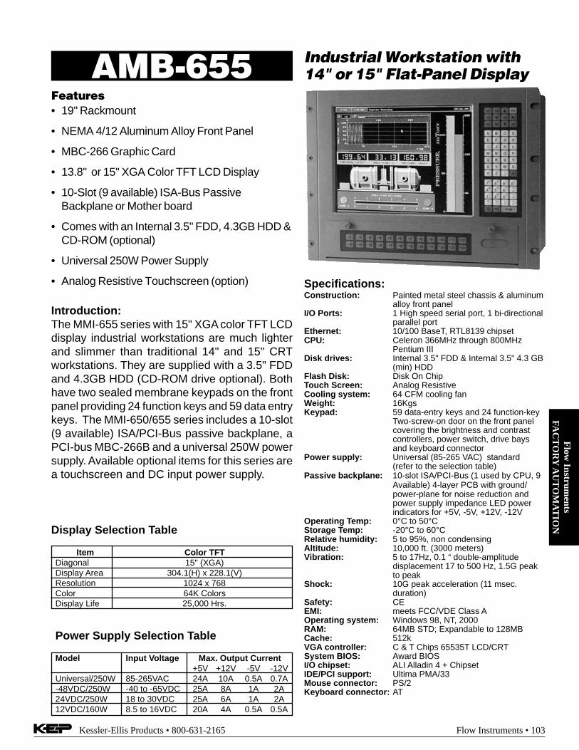
Flow
Instruments
FAC
TO
RY
AU
TO
MA
TIO
N
Kessler-Ellis Products • 800-631-2165 Flow Instruments • 103
Features• 19" Rackmount
• NEMA 4/12 Aluminum Alloy Front Panel
• MBC-266 Graphic Card
• 13.8" or 15" XGA Color TFT LCD Display
• 10-Slot (9 available) ISA-Bus PassiveBackplane or Mother board
• Comes with an Internal 3.5" FDD, 4.3GB HDD &CD-ROM (optional)
• Universal 250W Power Supply
• Analog Resistive Touchscreen (option)
Industrial Workstation with14" or 15" Flat-Panel DisplayAMB-655
Introduction:The MMI-655 series with 15" XGA color TFT LCDdisplay industrial workstations are much lighterand slimmer than traditional 14" and 15" CRTworkstations. They are supplied with a 3.5" FDDand 4.3GB HDD (CD-ROM drive optional). Bothhave two sealed membrane keypads on the frontpanel providing 24 function keys and 59 data entrykeys. The MMI-650/655 series includes a 10-slot(9 available) ISA/PCI-Bus passive backplane, aPCI-bus MBC-266B and a universal 250W powersupply. Available optional items for this series area touchscreen and DC input power supply.
Specifications:Construction: Painted metal steel chassis & aluminum
alloy front panelI/O Ports: 1 High speed serial port, 1 bi-directional
parallel portEthernet: 10/100 BaseT, RTL8139 chipsetCPU: Celeron 366MHz through 800MHz
Pentium IIIDisk drives: Internal 3.5" FDD & Internal 3.5" 4.3 GB
(min) HDDFlash Disk: Disk On ChipTouch Screen: Analog ResistiveCooling system: 64 CFM cooling fanWeight: 16KgsKeypad: 59 data-entry keys and 24 function-key
Two-screw-on door on the front panelcovering the brightness and contrastcontrollers, power switch, drive baysand keyboard connector
Power supply: Universal (85-265 VAC) standard(refer to the selection table)
Passive backplane: 10-slot ISA/PCI-Bus (1 used by CPU, 9Available) 4-layer PCB with ground/power-plane for noise reduction andpower supply impedance LED powerindicators for +5V, -5V, +12V, -12V
Operating Temp: 0°C to 50°CStorage Temp: -20°C to 60°CRelative humidity: 5 to 95%, non condensingAltitude: 10,000 ft. (3000 meters)Vibration: 5 to 17Hz, 0.1 “ double-amplitude
displacement 17 to 500 Hz, 1.5G peakto peak
Shock: 10G peak acceleration (11 msec.duration)
Safety: CEEMI: meets FCC/VDE Class AOperating system: Windows 98, NT, 2000RAM: 64MB STD; Expandable to 128MBCache: 512kVGA controller: C & T Chips 65535T LCD/CRTSystem BIOS: Award BIOSI/O chipset: ALI Alladin 4 + ChipsetIDE/PCI support: Ultima PMA/33Mouse connector: PS/2Keyboard connector: AT
Display Selection Table
Item Color TFTDiagonal 15" (XGA)Display Area 304.1(H) x 228.1(V)Resolution 1024 x 768Color 64K ColorsDisplay Life 25,000 Hrs.
Power Supply Selection Table
Model Input Voltage Max. Output Current+5V +12V -5V -12V
Universal/250W 85-265VAC 24A 10A 0.5A 0.7A-48VDC/250W -40 to -65VDC 25A 8A 1A 2A24VDC/250W 18 to 30VDC 25A 6A 1A 2A12VDC/160W 8.5 to 16VDC 20A 4A 0.5A 0.5A

Flo
w I
nstr
umen
tsFA
CT
OR
Y A
UT
OM
AT
ION
104 • Flow Instruments Kessler-Ellis Products • 800-631-2165
Dimensions:
Data-entry membrane keypad
Brightness & contrast controllers
Power switch
External keyboard connector
3.5" FDD & HDD drive bay
CD-ROM drive bay
Front antidust door
14" Flat panel display
Cooling fan
10-slot ISA/PCI backplane (Full length)
Hold-down clamp
Universal 250W power supply
1
2
3
4
5
6
7
8
9
10
11
12
Ordering Information:How To Order:EXAMPLE AMB-6501 T TSeries655 = AMB-655 Series includes:
15" color display, PCI-Bus MBC-266B graphic card,a 10-slot ISA/PCI-Bus passive backplane and auniversal 250W switching power supply
Display TypeT = XGA color TFT LCD display
OptionsT = Touchscreen option-48VDC = -40 to -65 VDC input power supply24VDC = 18 to 30 VDC input power supply12VDC = 8.5 to 16 VDC input power supplyCD = 40X CD-ROM Drive
For additional RAM consult factory

Flow
Instruments
FAC
TO
RY
AU
TO
MA
TIO
N
Kessler-Ellis Products • 800-631-2165 Flow Instruments • 105
Industrial HMI Panel PC withFlat-Panel DisplayAMB-2000/2020
Features• 10.4" or 12.1" VGA color TFT LCD display
• Heavy-duty steel chassis and NEMA 4/12compliant plastic front panel
• All-in-one SBC, MediaGX 233MHz
• Brightness and LCD power on/off controlleron the aluminum alloy front panel (aluminumfront panel optional)
• Four 16C550 RS-232C ports, one RS-232Cport can also be set as RS-422/485
• Disk Driver Space for CD-ROM, FDD andHDD
• DiskOnChip flash disk socket
• PC/104 expansion connector
IntroductionThe AMB-2000/2020 series panel PC's areindustrial computers that are designed forindustrial environments.. They are a fullfunction PC-base system with a 10.4" VGA(640 x 480) color TFT hi-brightness, long-lifetime LCD display. The compact dimensions areideal for automation applications where theinstallation space is critical. These PC's arecharacterized by their space saving feature andflexible selection of hardware. The AMB-2000/2020 series panel PC's feature a heavy-dutysteel chassis with a sealed plastic front panelthat meets the toughest industrial andenvironmental standards.
Specifications for AMB-2000Construction: Heavy-duty steel chassis & NEMA 4/12
plastic front panel.CPU: MediaGX 233MHzMemory: 64M DRAMDisplay: 10.4" VGA (640 x 480) TFT color LCDLCD/CRT controller: NS Cx5530 Chipset UMA supports
up to 4MB display memoryNetwork (LAN): Realtek RTL8139B 10/100Base-T
Ethernet controllerI/O ports: 4 serial ports: three RS-232, one RS-232/422/
485, 1 parallel port (support ECP/EPP), 1 keyboardport, 1 PS/2 mouse interface
Disk Drives: HDD and FDD or HDD and CD-ROMUSB connector: Dual USB ports onboardExpansion: PC/104 connectorMounting: Panel mountPower supply: Universal 70W switching power supplyDimension: (W x H x D) 306 x 228 x 95 mmGross Weight: 6.0 Kg

Flo
w I
nstr
umen
tsFA
CT
OR
Y A
UT
OM
AT
ION
106 • Flow Instruments Kessler-Ellis Products • 800-631-2165
Ordering Information
Part Number Description2000HT 10.4” Bright TFT Color LCD, (200 cd/m)
Cyrex MediaGX 233MHz CPU
Options (add to end of Part Number)T Touchscreen24V 24V power instead of 120VAC power12V 12V power instead of 120VAC power128M Memory expanded to 128MBNTW Windows NT 4.0 Workstation InstalledNTS Windows NT 4.0 Server (5 lic.) InstalledILINK Infilink Software Installed.
Unlimited Tags, Any DriverINTCD Internal Slim CDROM REPLACING
internal FDD. With this option, no internalFDD will be present. There is no externalFDD connector, so a USB floppy drive should bepurchased if needed.
USBFDD External USB Floppy Disk DriveEXTCD External CDROM Drive
AMB 2000
Dimensions
Specifications for AMB-2020Construction: Heavy-duty steel chassis & NEMA 4/12
plastic front panel.CPU: MediaGX 233MHzMemory: 64M DRAMDisplay: 12.1" SVGA (800 x 600) TFT color LCDLCD/CRT controller: NS Cx5530 Chipset UMA supports
up to 4MB display memoryNetwork (LAN): Realtek RTL8139B 10/100Base-T
Ethernet controllerI/O ports: 4 serial ports: three RS-232, one RS-232/422/
485, 1 parallel port (support ECP/EPP), 1 keyboardport, 1 PS/2 mouse interface
Disk Drives: HDD and FDD or HDD and CD-ROMUSB connector: Dual USB ports onboardExpansion: PC/104 connectorMounting: Panel mountPower supply: Universal 70W switching power supplyDimension: (W x H x D) 330 x 255 x 93 mmGross Weight: 5.0 Kg
LCD SpecificationsModel: AMB-2000 2020Display type: 10.4" TFT 12.1" TFT
color LCD color LCDMax. resolution: 640 x 480 800 x 600Max. colors: 256K 256KDot size (mm): 0.33 x 0.33 0.308 x 0.308Luminance (cd/m2): 200 200Viewing angle: 90° (h) 50° (v) 110°Temperature: 0° ~50° C 0° ~50° CVR Controller: Yes YesLCD MTBF (Hrs): 50,000 50,000Back Light MTBF (Hrs): 25,000 25,000
Part Number Description2000HT 12.1” Bright TFT Color LCD, (250 cd/m)
Cyrex MediaGX 233MHz CPU
Options (add to end of Part Number)T Touchscreen24V 24V power instead of 120VAC power12V 12V power instead of 120VAC power128M Memory expanded to 128MBNTW Windows NT 4.0 Workstation InstalledNTS Windows NT 4.0 Server (5 lic.) InstalledILINK Infilink Software Installed.
Unlimited Tags, Any DriverINTCD Internal Slim CDROM REPLACING
internal FDD. With this option, no internalFDD will be present. There is no externalFDD connector, so a USB floppy drive should bepurchased if needed.
USBFDD External USB Floppy Disk DriveEXTCD External CDROM Drive
AMB 2020

Flow
Instruments
FAC
TO
RY
AU
TO
MA
TIO
N
Kessler-Ellis Products • 800-631-2165 Flow Instruments • 107
15" Modular SystemIndustrial Panel PCAMB-2053 Series
Features• 15" XGA color TFT LCD display
• Heavy-duty steel chassis and NEMA 4/12compliant plastic front panel
• All-in-one Celeron 366MHz SBC
• Brightness and LCD power on/off controlleron the aluminum alloy front panel
• Disk Driver Space for CD-ROM, FDD & HDD
• DiskOnChip flash disk socket
• Two Free Slots for ISA/PCI or ISA
• PC/104 expansion connector
IntroductionThe AMB-2053 series panel PC's are industrialcomputers that are designed for industrialenvironments.. They are a full function PC-base system with a 15" XGA (1024x 768) colorTFT hi-brightness, long-life time LCD display.The compact dimensions are ideal forautomation applications where the installationspace is critical. These PC's are characterizedby their space saving feature and flexibleselection of hardware. The AMB-2053 seriespanel PC's feature a heavy-duty steel chassiswith a sealed plastic front panel that meets thetoughest industrial and environmentalstandards.
Specifications for AMB-2053(15" LCD+ACS-2303)Construction: Heavy-duty steel chassis & NEMA 4/12
plastic front panel.CPU: Celeron 366MHz through 800MHz Pentium IIIMemory: 64M DRAMDisplay: 15" XGA (1024x 768) TFT color LCDLCD/CRT controller: Chips 69000 VGA controller 2MB
SDRAM embedded. CRT & LCD panel support.I/O ports: 2 serial ports: one RS-232, one RS-232/422/
485, 1 parallel port (support ECP/EPP), 1 keyboardport, 1 PS/2 mouse interface
HDD: 2.5" HDD space or 3.5"HDDFDD: Slim-type FDD spaceCD-ROM: Slim-type CD-ROM spaceUSB connector: Pin head for Dual USB portExpansion: One PCI and one ISA (1/2 length)Mounting: Panel mountPower supply: Universal 70W switching power supplyDimension: (W x H x D) 395 x 277.4 x 134.2 mmGross Weight: 6.5 Kg

Flo
w I
nstr
umen
tsFA
CT
OR
Y A
UT
OM
AT
ION
108 • Flow Instruments Kessler-Ellis Products • 800-631-2165
Ordering Information
Part Number Description2003HT 15” TFT Color LCD (250 cd/m)
Intel Celeron 366MHz CPU
Options (add to end of Part Number)T Touchscreen24V 24V power instead of 120VAC power12V 12V power instead of 120VAC power64M Memory expanded to 64MB128M Memory expanded to 128MB256M Memory expanded to 256MBNTW Windows NT 4.0 Workstation InstalledNTS Windows NT 4.0 Server (5 lic.) InstalledINTCD Internal Slim CDROMEXTCD External CDROM DriveILINK Infilink Software Installed. Unlimited Tags, Any
Driver
AMB 2053
Dimensions
LCD SpecificationsModel: AMB-2053Display type: 15" TFT color LCDMax. resolution: 1024x 768Max. colors: 256KDot size (mm): 0.313 x 0.329Luminance (cd/m2): 250Viewing angle: 160°Temperature: 0° ~50° CVR Controller: YesLCD MTBF (Hrs): 50,000Back Light MTBF (Hrs): 25,000
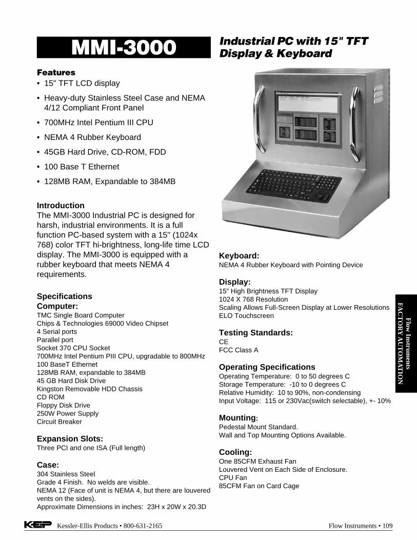
Flow
Instruments
FAC
TO
RY
AU
TO
MA
TIO
N
Kessler-Ellis Products • 800-631-2165 Flow Instruments • 109
Industrial PC with 15" TFTDisplay & KeyboardMMI-3000
Features• 15" TFT LCD display
• Heavy-duty Stainless Steel Case and NEMA4/12 Compliant Front Panel
• 700MHz Intel Pentium III CPU
• NEMA 4 Rubber Keyboard
• 45GB Hard Drive, CD-ROM, FDD
• 100 Base T Ethernet
• 128MB RAM, Expandable to 384MB
IntroductionThe MMI-3000 Industrial PC is designed forharsh, industrial environments. It is a fullfunction PC-based system with a 15" (1024x768) color TFT hi-brightness, long-life time LCDdisplay. The MMI-3000 is equipped with arubber keyboard that meets NEMA 4requirements.
SpecificationsComputer:TMC Single Board ComputerChips & Technologies 69000 Video Chipset4 Serial portsParallel portSocket 370 CPU Socket700MHz Intel Pentium PIII CPU, upgradable to 800MHz100 BaseT Ethernet128MB RAM, expandable to 384MB45 GB Hard Disk DriveKingston Removable HDD ChassisCD ROMFloppy Disk Drive250W Power SupplyCircuit Breaker
Expansion Slots:Three PCI and one ISA (Full length)
Case:304 Stainless SteelGrade 4 Finish. No welds are visible.NEMA 12 (Face of unit is NEMA 4, but there are louveredvents on the sides).Approximate Dimensions in inches: 23H x 20W x 20.3D
Keyboard:NEMA 4 Rubber Keyboard with Pointing Device
Display:15” High Brightness TFT Display1024 X 768 ResolutionScaling Allows Full-Screen Display at Lower ResolutionsELO Touchscreen
Testing Standards:CEFCC Class A
Operating SpecificationsOperating Temperature: 0 to 50 degrees CStorage Temperature: -10 to 0 degrees CRelative Humidity: 10 to 90%, non-condensingInput Voltage: 115 or 230Vac(switch selectable), +- 10%
Mounting:Pedestal Mount Standard.Wall and Top Mounting Options Available.
Cooling:One 85CFM Exhaust FanLouvered Vent on Each Side of Enclosure.CPU Fan85CFM Fan on Card Cage

Flo
w I
nstr
umen
tsFA
CT
OR
Y A
UT
OM
AT
ION
110 • Flow Instruments Kessler-Ellis Products • 800-631-2165
The MMI-3000 features a hinged backpanel which allows easy access to theinterior for quick upgrades andmaintenance.
20.00 11.00
23.0
0
3.25
20.31
Dimensions:
Ordering Information:
Part Number Description
MMI-3000 MMI-3000 Industrial Computer Includes:700MHz Intel Pentium PIII CPU, 128MBRAM, 4 Serial ports, Parallel port, 100BaseT Ethernet, 45 GB Hard Disk Drive,Kingston Removable HDD Chassis, CDROM, Floppy Disk Drive, 250W PowerSupply

Kessler-Ellis Products • 800-631-2165 Flow Instruments • 111
Flow
Instruments
SPE
CIA
L F
LO
W IN
STR
UM
EN
TS
KEPtrol F/C Measures NetFlow of Boiler Fuel
Features
• Displays Net Rate & Net Total (A – B) or (A + B)
• Pulse Input to 10 kHz Count Frequency
• Separate K-Factors for A and B inputs
• Set Point Alarms
• NEMA 4X/IP65 Front Panel
Description:The KEPtrol F/C is a special version of the KEPtrol R/T designed to measurethe net flow of boiler fuel. Separate K-Factors can be entered for A and B in-puts. Two SPDT relay alarm outputs are standard. A scaled pulse output isstandard for interfacing with remote devices. An analog output is available tointerface with strip chart recorders.
Specifications:Display: 8 digit, .55" high, 15 segment bright LED.Input Power: (Internally Fused)
A) 115 VAC ±15% or 12 to 27 VDCB) 230 VAC ±15% or 12 to 27 VDC
Current: 280 mA DC max. or 5.3 VA at rated AC voltage.Output Power: (on AC powered units only)
+12 VDC @ 100 mA and separate isolated 12 VDC @ 100 mA to allow±12 VDC or + 24 VDC, regulated ±5% worst case.The DC Outputs are supplied with resettable fuses.
Pulse Inputs:Thresholds: High: 3 to 30 VDC; Low: open or <1 VDCImpedance: 10 kΩFrequency: 10 kHz max. (min. on/off 100 µsec.)
Control Output:Open Collector: Sinks 250 mA max @ 30 VDCSPDT Relay: 10 amp, 115/240 VAC or 28 VDC
Temperature: 32° to 132°F (0° to 55°C)ET: Extended Temperature -40° to 158°F (-40° to 70° C)
Accuracy: 100% over specified temperature rangeHumidity: 0 to 90% (non-condensing)Memory: EEPROM stores all data for min. of 10 years if power is lost.Dimensions: See KEPtrol R/TListing: CE Compliant, UL/CSA Pending
FLOWtrol Batch Controller
Features
• Start/Stop Buttons and Remote Inputs
• Programmable K-Factor
• Batch Total and Grand Total
• Two DPDT Relay Outputs for Two Stage Shut Off
• Pulse Input to 20 kHz Count Frequency
Description:The FLOWtrol is a batch controller intended for use with pulse producingflowmeters. The FLOWtrol offers control outputs consisting of DPDT Re-lays rather than SPDT Relays. The Flowtrol may be applied in existing appli-cations seeking to expand their batching operations with compatible units.
The FLOWtrol was the fore runner to the BATCHtrol II. However, it lacks therate display, analog input and Easy Preset capabilities now available in theBATCHtrol II. The BATCHtrol II is recommended for all new applications.
Specifications:Display: 8 digit, .55" high, 15 segment bright LED.Input Power:
A) 115 VAC ±15% or 12 to 27 VDCB) 230 VAC ±15% or 12 to 27 VDC
Current: 280 mA DC max. or 5.3 VA at rated AC voltage.Output Power: (on AC powered units only)
+12 VDC @ 100 mA and separate isolated 12 VDC @ 100 mA to allow±12 VDC or + 24 VDC, regulated ±5% worst case.
Input: (count/start/stop/reset)High: 3 to 30 VDCLow: open or <1 VDCImpedance: 10 kΩFrequency: 20 kHz max.Inputs: Positive edge triggered, 3 µsec/61 µsec/5 msec selectabledebounce filtering.
Control Output: (preset and prewarn)DPDT relay, 5 amp, 115 or 230 VAC
Temperature: 32° to 132°F (0° to 55°C)Humidity: 0 to 90% (non-condensing)Memory: EEPROM stores all program and count data for minimum of 10
years if power is lost.Dimensions: See BATCHtrol II
Ordering InformationExample KFC8 A 3A 2 E 1 3KEPtrol F/COperating Voltage:
A: 110 VAC ±15% or 12 to 27 VDCB: 220 VAC ±15% or 12 to 27 VDC
Control Inputs:*3A: STD Pulse 3-30 VDC 20 kHz Max.*3B: As 3A, with 4.7 KΩ pull up resistors
Control Outputs:1: Open Collector2: SPDT Relay 10A
Input Speed:*A: 0-40 CPS (Inputs 3A, 3B)*C: 0-400 CPS (Inputs 3A, 3B)*E: 0-10K CPS (Inputs 3A, 3B)*Dip switch selectable, all units can be field modified easily.
Options: (Multiple Options Available)1: RS232 Serial Interface2: RS422 Serial Interface3: 4-20 mA Output (Input 3A or 3B only)3X: 0-20 mA Output (Input 3A or 3B only)3Y: 0-5VDC Output (Input 3A or 3B only)3Z: 0-10VDC Output (Input 3A or 3B only)ET: Extended Temperature -40° to 158°F (-40° to 70° C)ET not available with analog outputsCSA: CSA Approved Unit (pending) ....................... (consult factory)
Accessories:NEMATROL - NEMA 4X/IP 65 Enclosure (see Accessories)XTROL7/4- Explosion proof housingP1000 Printer (see Accessories)
Ordering InformationExample FLO8 A 1FLOWtrolOperating Voltage:
A: 110 VAC ±15% or 12 to 27 VDCB: 220 VAC ±15% or 12 to 27 VDC
Options:1: RS232 Serial Interface2: RS422 Serial Interface
Accessories:NEMATROL - NEMA 4X/IP 65 Enclosure (see Accessories)
XTROL7/4- Explosion proof housingP1000 Printer (see Accessories)

Flo
w I
nstr
umen
tsSP
EC
IAL
FL
OW
IN
STR
UM
EN
TS
112 • Flow Instruments Kessler-Ellis Products • 800-631-2165
MASSbatch TEMP./DENSITY COMPENSATEDBATCH CONTROLLER
Features• Display Mass or Corrected Volume, Rate,
Grand Total, Temperature or Density
• Accepts 4-30V Inputs or Pulses Directly FromMagnetic Pickup Meters (no pre-amp required)
• Takes a Direct 100Ω Platinum RTD or AnalogSignal For Compensation Input
• Two Way RS232/422 Communications
• Scalable 4-20mA Output of Rate/Total
Description:Featuring 8 digits of bright, .55", alpha-numeric display, the MASSbatchcan accept up to 10,000 pulses per second and a direct 100Ω platinumRTD or analog input. The MASSbatch has two separate, 8 digit, floatingdecimal, “K” factors to convert the inputs to meaningful total and ratedata. The user, with the push of a button, can toggle back and forth toview the total of the batch, the rate of flow, temperature or density andthe grand total. Two control outputs are provided for two-stage valvecontrol.A scaled pulse output is also provided by an open collector driver. Sincethe output frequency is user selectable at 10, 200, 2K or 20K Hz, the unitcan transmit the count data to remote electro-mechanical or electroniccounters as well as computers, programmable controllers or other monitorequipment.An optional analog output allows the user to select low and high settingsto control strip recorders or other peripherals.
Specifications:DISPLAY: 8 Digit, .55" High, 15 Segment, Red Orange, LED.INPUT POWER: (Internally Fused)A: 110 VAC ±15% or 15 to 27 VDCB: 220 VAC ±15% or 15 to 27 VDCCURRENT: Maximum 350 mA DC or 8.8 VA at rated AC voltage.OUTPUT POWER: (On AC powered units only):+12 VDC at 100mA. Separate Isolated 12 VDC at 100mA to allow +12VDC or +24 VDC regulated +5% worst case.The 24VDC Output is supplied with a resettable fuse.MEMORY: EEPROM stores all program and total data for minimum of 10years if power is lost.PULSE INPUT:3A: (Standard) 4-30VDC 30 k Ohm impedance to GND, 10 kHz max.input speed (min. on/off 50µsec.).3C: (Magnetic Pickup) 30mV to 30V P/P min., 2 Hz to 5 kHz InputSpeed.ENVIRONMENTAL:Temperature:
Operating: +41°F (5°C) to +130°F (+54°C).Storage: -40°F (-40°C) to +200°F (+93°C).ET: Extended Temperature -40° to 158°F (-40° to 70° C)
Humidity: 0-90% NoncondensingDimensions: See BATCHtrol IIListing: CE Compliant, UL/CSA PendingFACTORED OUTPUT: The MASSbatch gives one pulse out for eachfactored count. The open collector sinks 30 VDC maximum to 1 voltmaximum at 100mA maximum. Output speed is user selectable (seetable below). An internal buffer holds up to 10,000 pulses for output atthe selected frequency before “DATALOST” flashes, indicating pulsesare lost. If factored rate exceeds 7 digits “RFF…” flashes. These alarmsindicated that speed has been exceeded.
Ordering InformationExample: MB8 A 3A 2 H R 3Series:
MASSbatchOperating Voltage:
A: 110 VAC ±15% or 15 to 27 VDCB: 220 VAC ±15% or 15 to 27 VDC
Count Inputs:3A: (STD) Pulse 4-30 VDC 10 kHz Max. (jumper selectable)3C: (Mag. Pickup) 30mV 2 Hz to 10 kHz (jumper selectable)
Control Outputs:1: Open Collector2: SPDT Relay 10A
Input Speed:L: (Low Speed) 0-40 HzH: (High Speed) 0-10 kHz
Options: (Multiple Options Available)R: RTD and 4-20mA input (jumper selectable) ....... Standard1: RS232 Serial Interface2: RS422 Serial Interface3: 4-20 mA Output (jumper selectable)3Y: 0-5VDC Output (jumper selectable)3Z: 0-10VDC Output (jumper selectable)4: 16 Point LinearizationET: Extended Temperature:
-40° to 158°F (-40° to 70° C)CSA: CSA Approved Unit (pending) ............ (consult factory)
Accessories:NEMATROL 4X1 - NEMA 4X/IP 65 Enclosure for
wall mounting accommodating 1 ‘TROL Series unit.NEMATROL 4X2 - NEMA 4X/IP 65 Enclosure for
wall mounting accommodating 2 ‘TROL Series unit.FLEXCOVER #36120XTROL7/4- Explosion proof housingP1000 Printer (see Accessories)

Kessler-Ellis Products • 800-631-2165 Flow Instruments • 113
Flow
Instruments
AC
CE
SSOR
IES
XTROL 7/4 Explosion Proof Housingfor 'trol Products
Features:• Compatible with all Standard Size "trol" and
"SUPERtrol" Family of Products
• Meets NEMA 7 & 4 Specs.
• For use in Class 1, Division 1, Groups C & D
• For use in Class 2 & 3, Division 1,Groups E, F & G
• FM, CSA Approved
• Specials Available for Custom Conduit Entries
Specifications:This housing is designed and manufactured in compli-ance with FM Standards 3600 & 3615 and CSA StandardC22.2 No. 30-M1986 for use in Class I, Division I,Groups C & D and Class II an III, Division I, Groups E, F& G hazardous locations. It is certified by:
ADALETFM (file# JI 0V2A6.AE)CSA (file # LR36172).
It is made from cast aluminum and sealed to meetNEMA 7 and 4 specifications. This is accomplished byneoprene gaskets retained in machined grooves in thecovers and buttons. The front button actuators have the same easy-to-usekeypad layout that has become the trademark of the KEP"trol" and "SUPERtrol" series. 6 blind threaded holes areprovided for mounting with 2 each 1/2" NPT openings forwiring. To install a unit, the 16 front 3/16" allen screws mustbe removed and the "trol" mounted in the sub panel pro-vided. If the assembly option is ordered, only the 8 back capscrews need to be removed to complete the wiring to anoptional pluggable connector. Empty weight is 26 lbs.
XTROL 7/4*Example: XTROL7/4 BT2 ASeries:
XTROL7/4 (housing only)Mounting Hardware:
(Includes labels and two piece connector)BT2 = BATCHtrol IIMB = MASSbatchFLO = FLOWtrolKFC = KEPtrol F/CKP8 = KEPtrol CONTROLLERS SOLDKRT = KEPtrol R/T SEPARATELYMFC = Mass Flow ComputerDPFC = DPFCST1** = SUPERtrol-IST1LE** = SUPERtrol-I LEST2** = SUPERtrol-IILT2** = LEVELtrol-IIX = No Mounting Hardware
Assembly By KEP:A = Assembled by KEPX = No Assembly
Note: When placing the order, the unit part number directlyfollowing the XTROL part number on the PurchaseOrder is the one that will be assembled into the XTROLhousing.
** See also XHV series enclosure.

Flo
w I
nstr
umen
tsA
CC
ESS
OR
IES
114 • Flow Instruments Kessler-Ellis Products • 800-631-2165
XTROL 7/4 Dimensions:
4.5(114.3)
1.13(28.6)
2.28(58)
9.31(236.5)
12.06(306.3)
3.81(96.8)
6.56(166.6)
.28 ±.02(7.1 ±.5)
1.31(33.3)
8.88(225.5)3.5
(88.9)
10.19(258.8)
2.5(63.5)
2.5(63.5)
5.09(129)
3.0(76.2)
1/4" - 20UNC-2BTAP x 5/16" DEEP(6) HOLES CENTEREDON THREE SIDES FORMOUNTING
1/2"- 14 NPT PLUGS(2 PLACES)
10.6(269.2)
1/4" - 20UNC-2BTAP x 5/16" DEEP(6) HOLES CENTEREDON THREE SIDES FORMOUNTING
3.5(88.9)
3(76.2)
2.13(54)
1.75(44.5)
2.34(59.4)
5.1(129.5)
.25(6.35).5
(12.7)
4.63(117.5)
10.19(258.8)
3.13(79.4)
3.13(79.4)
3(76.2)
.5(12.7)
Assembly:If HOUSING ONLY is purchased, all front allen screws and front must be removed. Removefour allen screws so that the 'trol product can be mounted in the internal bracket (gasket notused; top of bracket is the thinner side). Wiring should be done before installing 'trol in thehousing unless the MOUNTING HARDWARE with two piece connector is purchased. If theunit is assembled by KEP, only remove the back plate. The pluggable connector can be wiredat back.

Kessler-Ellis Products • 800-631-2165 Flow Instruments • 115
Flow
Instruments
AC
CE
SSOR
IES
XHV Series X-Proof Housing for ViewingDisplays in Hazardous Areas
Features:• Available for 1/8 DIN and DIN 144 x 72 mm
Cases
• Meets NEMA 7 & 4 Specs.
• For use in Class 1, Division 1, Groups C & D
• For use in Class 2 & 3, Division 1,Groups E, F & G
• UL, cUL Approved
• Magnetic Reset Switch Available
Specifications:This housing is designed and manufactured in compli-ance with UL Standard No. 1203 and was investigated toCSA Standard C22.2 No. 30-M1986 by UL for use inClass 1, Division 1, Groups C & D and Class II & III,Division I, Groups E, F & G hazardous locations.
Certified by:ADALETUL (file# E81696 )
The housing is made from cast aluminum and sealedto meet NEMA 7 and 4 specifications.
To install a unit, the cover must be removed and theKEP unit mounted in the sub panel provided.
Empty weight:XHV = 19 lbs.XHVD = 22 lbs.
6.25(158.8)
9.12
5(2
31.8
)
6.75(171.5)
10.5
(266
.7)
7.75
(196
.9)
7.75(196.9)
3.25(82.6)
2.25(57.2)
H
2.25(57.2)
HXHV = 8.5 (215.9)XHVD = 11.5 (292.1)
1/2" - 14 NPT Plugs(2 Places)
Dimensions:
Ordering InformationExample: XHV 7/4 A A S1Series:
XHV 7/4 (8.5" high for INT69, MRT, Reporter, etc.)XHVD 7/4 (11.5" high for Supertrol 1 and 2)
Mounting Sub Panel:A = Panel for (1) 1/8 DIN unit (INT69, MRT, etc.)B = Panel for (2) 1/8 DIN units (INT69, MRT, etc.)C = Panel for (1) DIN 144 x 72mm unit (ST1, ST2, LT2, Reporter)
Assembly By KEP:A = Assembled by KEPX = No Assembly
Options:S1 = 1 Magnetic Reset Switch and MagnetS2 = 2 Magnetic Reset Switches and Magnet
Accessories:XHVA-1 = Magnetic SwitchXHVA-2 = Actuating Magnet
Note: When placing the order, the unit part number directlyfollowing the XHV part number on the Purchase Order is theone that will be assembled into the XHV housing.

Flo
w I
nstr
umen
tsA
CC
ESS
OR
IES
116 • Flow Instruments Kessler-Ellis Products • 800-631-2165
NEMAtrol NEMA 4X/IP65 Enclosures For'trol & 1/8 DIN Cases
Application:Ideal for use in most petro-chemical plants, sewage plants,food processing areas, packing plants, electro-platingplants, etc.
Construction:• Molded fiberglass reinforced polyester material has
excellent chemical resistance and outstanding physicalproperties.
• Fiberglass material is easily punched, drilled, filed orsawed.
• Oil-resistant gasket attached with oil-resistant adhesive.
• The enclosures have corrosion-resistant fiberglasshinges and spring-loaded fiberglass latches attachedwith monel screws.
Physical Enclosure ASTMProperties Value MethodFlexural Strength 17,000 PSI D-790Heat Distortion 400° F D-648Water Absorption (24hrs.) .5% D-570Tensile Strength 6,500 PSI D-651Specific Gravity 1.8 D-792Flammability 94-5V UL94Dielectric Strength 400 V.P.M D-149Arc Resistance 180 Sec. D-495
Dimensions:
L
W
K
J
Part Number W L K J
NEMA-1/8DIN 7.86 8.97 1.00 4.38(200) (228) (25) (111)
NEMAtrol4X & 9.86 12.97 1.75 5.13NEMAST4X (250) (329) (44) (130)
Features
• Compatible with all Standard Size "trol",SUPERtrol & 1/8 DIN Products
• Meets NEMA 4X/IP65 Specs.
• Quick-Release Latches
• Light Weight
Ordering InformationPart NumberNEMAtrol4X (NEMA 4X enclosure for all standard 'trol units
7.365" x 2.495" cutout)NEMAtrol 4x0 (no cutout)NEMAtrol 4x1 (1 cutout)NEMAtrol 4x2 (2 cutouts)
NEMAST4X (NEMA 4X enclosure for SUPERtrol series)NEMAST 4x1 (1- 5.43” x 2.68” cutout for SUPERtrol series)NEMAST 4x2 (2- 5.43” x 2.68” cutout for SUPERtrol series)
NEMA-1/8DIN (NEMA 4X enclosure for all 1/8 DIN size units)NEMA-1/8DIN 4x0 (no cutout)NEMA-1/8DIN 4x1 (1 cutout)NEMA-1/8DIN 4x2 (2 cutouts)
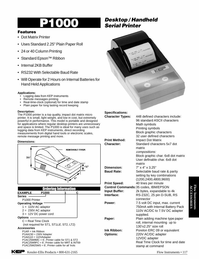
Kessler-Ellis Products • 800-631-2165 Flow Instruments • 117
Flow
Instruments
AC
CE
SSOR
IES
Features• Dot Matrix Printer
• Uses Standard 2.25" Plain Paper Roll
• 24 or 40 Column Printing
• Standard Epson™ Ribbon
• Internal 2KB Buffer
• RS232 With Selectable Baud Rate
• Will Operate for 2 Hours on Internal Batteries forHand Held Applications
Desktop / HandheldSerial PrinterP1000
Specifications:Character Types: 448 defined characters include:
96 standard ASCII charactersMath symbolsPrinting symbolsBlock graphic characters32 user defined characters
Print Method: Impact Dot MatrixCharacter: Standard characters 5x7 dot
matrixcompositions:Block graphic char. 6x8 dot matrixUser definable char. 6x8 dotmatrix
Dimension: 7" x 4" x 3.25"Baud Rate: Selectable baud rate & parity
setting by key combinations(1200,2400,4800,9600)
Print Speed: 40 lines per minuteControl Commands:35 codes, IBM/EPSONInput Buffer: 2k bytes, expandable to 4kInterface: RS-232C, 25 pin D-SUB, RS
connectorPower: 7.5 volt DC input, max. current
750mA with Internal Battery Pack110V AC/DC to 7.5V DC adaptersupplied.
Paper: Plain adding machine type paperroll, internal mounting up to130’x2.25" size roll
Ink Ribbon: Porelon ERC 09 or equivalentOptions: 220V AC/DC adapter
12VDC adapterReal Time Clock for time and datestamp at command
Applications:• Logging data from KEP instruments• Remote messages printing• Real-time-clock (optional) for time and date stamp• Plain paper for long lasting record keeping
Description:The P1000 printer is a top quality, impact dot matrix microprinter. It is small, light weight, and low in cost, but extremelypowerful in performance. This model is portable and designedfor applications where regular desktop printers are unnecessaryand space is limited. The P1000 is ideal for many uses such aslogging data from KEP instruments, direct recordingmeasurements from digital hand tools or electronic scales,remote message printing and more.
Dimensions:
Ordering InformationEXAMPLE P1000 1 CSeries
P1000 PrinterOperating Voltage
1 = 110V AC adaptor2 = 230V AC adaptor3 = 12V DC power cord
OptionsC = Real Time Clock (not required for ST1, ST1LE, ST2, LT2)
AccessoriesP1AR = Ink RibbonP1AA230 = 230V AdapterP1AA110 = 110VAdapterP1AC25M9MC = 6', Printer cable for ST1 & ST2P1AC25M9FC = 6', Printer cable for MRT & INT69P1AC25M25MS = 6', Printer cable for all 'trols

Flo
w I
nstr
umen
tsA
CC
ESS
OR
IES
118 • Flow Instruments Kessler-Ellis Products • 800-631-2165
Features• Worlds Smallest Slip Printer
• Only 1.6 Kg
• Epson's ESC/POS Command Set
• Easy-To-Use Touch Panel
• Four Print Directions
• Auto Eject
Miniature Slip PrinterP295
Specifications
Print Method 7-pin, serial impact dot matrixPrint Font
Font 5 x 7/7 x 7Column capacity 35 / 42 columnsCharacter size(mm) 1.6 (W) x 2.9 (H) / 1.3 (W) x 2.9 (H)Character set 95 Alphanumeric
32 International128 x 3 Graphic
Characters Per Inch 13.5 CPI / 16.2 CPIInterface RS-232CData Buffer 512 bytesPrint Speed 2.1 LPSPaper
Dimensions (mm) 80(W) x 69(L) x to 182(W) x 257(L)Thickness (mm) 0.09 to 0.35
Copy Capability One original and two copiesInked Ribbon ERC-27 (Purple)Power 24 DVC± 10%Current Consumption Approx. 600 mAOverall 180(W) x 19.5(D) x 101.5(H) mmDimensionsWeight 1.6 kg (Approx)EMI Standard VCC # 1, FCC class A, CE markingSafety Standards UL / C-UL / TUV
Description:Just 1.6kg and ultra compact, the P295 is the worldssmallest slip printer. Select from among 4 print sizesand four printing directions. Or, use page mode totell the printer where to print the page. The P295 isalso equipped with a host of user-friendly features,such as an easy-to-operate touch panel and anautomatic paper eject function.
The P295 offers printing capabilities of normal,double and quadruple size print in either horizontalor vertical formats. The P295 will print multi-partcopies. original and two copies and supports dualcash drawer capability. The P295 is uses a serialinterface and meets all world-wide regulatory re-quirements including UL, CSA and CE mark. TheP295 utilizes the PA295 Universal Power SupplyAdaptor which is an auto-switching supply. TheP295 is Windows and OPOS compliant.
How To Order:EXAMPLE P295
SeriesP295 Slip Printer
AccessoriesPA295 = Universal AC Power Supply AdaptorPA295DC = Power Supply Adaptor for DC OperationP2CA25M9ML6 = 6’ Serial Cable for SUPERtrol I,
SUPERtrol ILE, LEVELtrol II,SUPERtrol II

Kessler-Ellis Products • 800-631-2165 Flow Instruments • 119
Flow
Instruments
AC
CE
SSOR
IES
Features:• Screw Terminal Connections
• 250 mA of Regulated Power at 5 and 12 VDC
• 115/230 Volt 50/60 Hz Input
• Easily Mounted
• 5, 12 and 24 VDC Models
115 SeriesCased Power Supply
Power Supplies: 115-5, 115-12, 115-24
Applications:A compact supply to power various DC operated peripherals andinputs/output modules on PLC’s, or transmitters in process con-trol.
Description:This module converts 115 VAC to DC. The 115-5 and 115-12provide 250 mA of regulated DC for all of your 5VDC and 12VDCapplications. Model 115-24 is available for all regulated 24VDC at100mA applications.
Listing: CE Compliant
Sample Hookup to KAL-D R/T
115-12POWERSUPPLY
-
+
D08N (NPN)
BLKBLUBRN
COMMONSLOW SPEED INPUTPERIOD/GATED MODE SELECTHIGH SPEED INPUT+10 to 30 VDC SUPPLY
12345
115 VAC
Features:• Ultra Low Speed to 15 kHz Operation.
• 20 mV to 50 V Sensitivity.
• 100 mA Current Sinking Output.
• 11 to 26 VDC Power Supply Range.
• Easy Mount Metal Housing.
• Screw Terminal Hookup.
AMP-1Preamp & Signal Conditioner
for Magnetic Pickups
Description:The KEP AMP 1 amplifies the low level signals from a magneticpickup or flow transmitter by a factor of more than a hundred timesto drive any ratemeter, counter or controller. The unit uses only 30mA and operates from 11 to 26 VDC. It has a 2.7K pullup resistorattached to the open collector output and sinks a minimum of 100mA to less than 1 V from a maximum of 26 VDC. It is mounted in arugged 2" x 3" metal housing with screw terminals for easyinstallation. Operating temperature is 32 to 140° F (0 to 60° C).
Note: The low voltage line from the magnetic pickup to the AMP-1should be less than 10 ft. in length, shielded and isolated fromrelays, solenoids or other sources of electrical noise (let the outputline make the long run). If the input is too sensitive, lower the 1.1Kinput impedance by adding a 220 to 1K ohm resistor across TB1,pins 1 and 2, to increase noise immunity.
A special version, the AMP1-10k, is available with 10 kΩ impedancefor use with turbine and paddle wheel flowmeters.
Listing: CE Compliant
Mounting: (115 & AMP-1 Series) .15(3.8)
2.2(55.9)
3.00(76.2)
1.4(35.6)
.67(17)
Sample Hookup :
3 OUTPUT2 GND1 11-26 VDC
@ 30 mA
TB2
1 GND2 INPUT
3 SHIELD
TB1
GEAR OR TURBINE
MAGNETICPICKUP
Ordering InformationModelAMP 1: Standard unitAMP-1-10k: AMP-1 with 10 kΩ input impedance
Options:E-Explosion Proof Housing (add E to end of part number)
Ordering InformationPart Number115-5 115VAC to 5VDC for all 5 Volt applications115-12 115VAC to 5VDC for all 12 Volt applications115-24 115VAC to 5VDC for all 24 volt applications230-24 230VAC to 5VDC for all 24 volt applications
Options:E-Explosion Proof Housing (add E to end of part number)

Flo
w I
nstr
umen
tsA
CC
ESS
OR
IES
120 • Flow Instruments Kessler-Ellis Products • 800-631-2165
SPARE PARTSORDER NO. DESCRIPTIONModel 36120 Flex CoverKRTBEZEL Front panel bezel for KEPtrol R/TBT2BEZEL Front panel bezel for BT2KEPTROLBEZEL Front panel bezel for KEPtrolMFCBEZEL Front panel bezel for MASStrolFLOWBEZEL Front panel bezel for FLOWtrolDPFCBEZEL Front panel bezel for DPFCMBBEZEL Front panel bezel for MASSbatchLVTBEZEL Front panel bezel for LEVELtrolKFCBEZEL Front panel bezel for KEPtrol F/CST1LELCDFRONT LCD Front panel assembly for SUPERtrol ILEST1LEVFDFRONT VFD Front panel assembly for SUPERtrol ILEST1LCDFRONT LCD Front panel assembly for SUPERtrol IST1VFDFRONT VFD Front panel assembly for SUPERtrol IST2LCDFRONT LCD Front panel assembly for SUPERtrol IIST2VFDFRONT VFD Front panel assembly for SUPERtrol IILT2LCDFRONT LCD Front panel assembly for LEVELtrol IILT2VFDFRONT VFD Front panel assembly for LEVELtrol IIKP8CASE Case for KEPtrolKRTCASE Case for KEPtrol R/TBT2CASE Case for BT2FlOCASE Case for FlowtrolMASSCASE Case for MASStrolDPFCCASE Case for DPFCST1LEREAR Rear Case for SUPERtrol ILEST1REAR Rear Case for SUPERtrol IST2REAR Rear Case for SUPERtrol IILT2REAR Rear Case for LEVELtrol IIModel 34503 Mounting Kit for: MRT series,
INT69 series, BEACON seriesSTMOUNT Mounting Kit for: ST1series,
ST2 series, LT2 seriesTROLCLAMP Mounting Kit (4 clamps & gasket)*BATCHMAINRT3L KP8, KRT, BT2 Mainboard*FLOWTROLMAIN FLOWtrol Mainboard*MASSMAINAC MASStrol Mainboard, AC Power*MASSMAINDC MASStrol Mainboard, DC Power ***DPFCMAINAC DPFC Mainboard, AC Powered*DPFCMAINDC DPFC Mainboard, DC Powered ***ST1LEMAINDC2 SUPERtrol ILE Mainboard,
DC Powered, 2 Relays*ST1LEMAINDC4 SUPERtrol ILE Mainboard, **
DC Powered, 4 Relays*ST1LEMAINAC2 SUPERtrol ILE Mainboard,
AC Powered, 2 Relays*ST1LEMAINAC4 SUPERtrol ILE Mainboard, **
AC Powered, 4 Relays*ST1MAINDC2 SUPERtrol I Mainboard, **
DC Powered, 2 Relays*ST1MAINDC4 SUPERtrol I Mainboard, **
DC Powered, 4 Relays*ST1MAINAC2 SUPERtrol I Mainboard, **
AC Powered, 2 Relays*ST1MAINAC4 SUPERtrol I Mainboard, **
AC Powered, 4 Relays*ST2MAINDC2 SUPERtrol II Mainboard,
DC Powered, 2 Relays*ST2MAINDC3 SUPERtrol II Mainboard,
DC Powered, 3 Relays*ST2MAINAC2 SUPERtrol II Mainboard,
AC Powered, 2 Relays*ST2MAINAC3 SUPERtrol II Mainboard,
AC Powered, 3 Relays*LT2MAINDC2 LEVELtrol II Mainboard, **
DC Powered, 2 Relays*LT2MAINDC4 LEVELtrol II Mainboard, **
DC Powered, 4 Relays*LT2MAINAC2 LEVELtrol II Mainboard, **
AC Powered, 2 Relays*LT2MAINAC4 LEVELtrol II Mainboard, **
AC Powered, 4 RelaysKEPTROLDISP KP8, KRT, BT2, FLO8 Display BoardMASSTROLDISP MASStrol & DPFC Display Board
*PROM sold separately (see _Trol Program Chips at right)**Specify voltage when ordering
Spare PartsORDER NO. DESCRIPTIONEPLDMRTIN3 High Impedance input chip for MinitrolEPLDMRTIN5 Up/down control input chip for MinitrolEPLDMRTIN9 Quadrature input chip for Minitrol
MINITROL Input Chips
...TROL Program Chips
ORDER NO. DESCRIPTIONPROMBT2 PROM for BATCHtrol IIPROMBT216PT PROM for BT2 w/16PtPROMFLO PROM for FLOWtrolPROMKFC PROM for KEPtrol F/CPROMKP8 PROM for KEPtrolPROMKRT PROM for KEPtrol R/TPROMKRT16PT PROM for KRT w/16PtPROMMFC PROM for MASStrol(2 chips)PROMRS PROM for Trol RS422 & RS232PROMRS422M PROM for Trol RS422MPROMMB PROM for MASSbatchPROMMB16PT PROM for MASSbatch w/ 16PtPROMDPFC PROM for DPFC (2 chips)PROMLTR PROM for LEVELtrolPROMMS627 PROM for MS627 (2 chips)PROMST1LE PROM for SUPERtrol-ILEPROMST1 PROM for SUPERtrol-IPROMST2 PROM for SUPERtrol-IIPROMLT2 PROM for LEVELtrol-IIPROMST485 PROM for RS-485 option card for SUPERtrolPROMPEELST2 PEEL PROM for SUPERtrol-II
ORDER NO. DESCRIPTION34235 Non Keyboard Front Panel34234 Keyboard Front Panel
INT69 & MINITROL ACCESSORIES
ORDER NO. DESCRIPTIONMASSRS232 RS 232 Interface Kit
MASStrol & DPFC Retrofit Boards
BT2 & KRT Retrofit Boards
ORDER NO. DESCRIPTION3A/3B High Imp. 3A & 3 B Pulse InputsBA8ANA4-20MA Input 5A; 4-20 mA InputBA8ANA0-20MA Input 5B; 0-20 mA InputBA8ANA1-5V Input 5C; 1-5 V InputBA8ANA0-5V Input 5D; 0-5 V InputBA8ANA0-10V Input 5E; 0-10 V InputBATCHSQROOT Input 6A; Square Law Input
*BA8IO7A4-20M Input 7A; 4-20 mA In 4-20 mA Out*BA8IO7B0-20M Input 7B; 0-20 mA In 4-20 mA Out*BA8IO7C1-5V Input 7C; 1-5 V In 4-20 mA Out*BA8IO7D0-5V Input 7D; 0-5 V In 4-20 mA Out*BA8IO7E0-10V Input 7E; 0-10 V In 4-20 mA OutBA8ANAOUT4-20 4-20mA out for 3A & 3B InputsBA8ANAOUT0-20 0-20mA out for 3A & 3B InputsBA8ANAOUT0-5 0-5V out for 3A & 3B InputsBA8ANAOUT0-10 0-10V out for 3A & 3B InputsBATCHRS232 RS 232 Interface KitBATCHRS422 RS 422 Interface KitMB8IN MASSbatch Input
*MB8IN/OUT MASSbatch Input w/ 4-20mA Out* For Other Outputs:
Add suffix X for 0-20 mA (i.e. BA8IO7A4-20MX, MB8IN/OUTX)Add suffix Y for 0-5 V out (i.e. BA8IO7A4-20MY, MB8IN/OUTY)Add suffix Z for 0-10 V out (i.e. BA8IO7A4-20MZ, MB8IN/OUTZ)