Kent Design - Technical Appendix · PDF file2.8 Street Lighting ... 3.6.5 Pedestrian Crossings...
63
KentDesign Kent Association of Local Authorities a guide to sustainable development TECHNICAL APPENDIX
Transcript of Kent Design - Technical Appendix · PDF file2.8 Street Lighting ... 3.6.5 Pedestrian Crossings...

KentDesign
K e n t A s s o c i a t i o n o f L o c a l A u t h o r i t i e s
a g u i d e t o s u s t a i n a b l e d e v e l o p m e n t
T E C H N I C A L A P P E N D I X

cont
ents
KentDesign

1. PROCESS........................................................................................................................................................9
1.1 Technical Assessment And Safety Audit...........................................................................................................................................10
1.1.1 Introduction and Summary of Process .........................................................................................................................................10
1.1.2 Outline Design Technical Assessment and Safety Audit - Stage 1 ................................................................................................11
1.1.3 Detail Design Technical Assessment and Safety Audit- Stage 2 .................................................................................................11
1.1.4 Phase 3 of the Technical Assessment and Safety Audit Process ...................................................................................................12
1.1.5 Highway Structures ......................................................................................................................................................................12
1.2 Adoption ..........................................................................................................................................................................................13
1.2.1 Process..........................................................................................................................................................................................13
1.2.2 Adoption Policy.............................................................................................................................................................................15
1.2.3 Advance Payments Code (apc) Procedure ................................................................................................................................16
1.2.4 Section 38 Agreement of the Highways Act 1980 .....................................................................................................................16
1.3 A Sustainable Approach To Highways Construction .......................................................................................................................18
1.3.1 Introduction ..................................................................................................................................................................................18
1.3.2 Sustainability Action Plans ..........................................................................................................................................................19
1.3.3 Waste Audits .................................................................................................................................................................................19
1.3.4 Reasons for Waste Being Generated ............................................................................................................................................21
1.3.5 Information Contained in a Waste Audit ...................................................................................................................................21
1.3.6 Enabling Specification Clauses ......................................................................................................................................................21
1.3.7 References for Implementing Sustainability ...............................................................................................................................22
2. DESIGN ......................................................................................................................................................23
2.1 Highway Standards for Residential Roads........................................................................................................................................24
2.1.1 Highway Layout Design Guidance .............................................................................................................................................24
2.1.2 Town Centre Scenario 1 ............................................................................................................................................................25
2.1.3 Town Centre Scenario 2...............................................................................................................................................................25
2.1.4 Town Edge Scenario 1 .............................................................................................................................................................26
2.1.5 Town Edge Scenario 2 ..................................................................................................................................................................26
2.2 Geometric Requirements for Residential Roads ...........................................................................................................................27
2.2.1 Turning Facilities............................................................................................................................................................................27
2.2.2 Gradients ......................................................................................................................................................................................27
2.2.3 Junctions........................................................................................................................................................................................28
2.3 Highway Standards for Industrial and Commercial Roads...............................................................................................................29
2.3.1 General .........................................................................................................................................................................................29
2.3.2 Types .............................................................................................................................................................................................29
2.3.3 Geometric Requirements ............................................................................................................................................................30
2.3.4 Additional Requirements for Industrial and Commercial Roads...................................................................................................31
2.4 Cycleway Design .............................................................................................................................................................................31
2.4.1 Cycleway Standards..................................................................................................................................................................... 32
2.5 Summary of the Highway Standards................................................................................................................................................32
cont
ents
c o n t e n t s
4 KentDesign

2.5.1 Guidance for the Table of Standards ..........................................................................................................................................34
2.6 Drainage...........................................................................................................................................................................................34
2.6.1 Design of Surface Water Drainage Systems ...............................................................................................................................34
2.6.2 Catchpits and Oil Interceptors .....................................................................................................................................................35
2.6.3 Pipes, Pipe Trenches, Laying and Jointing Pipes............................................................................................................................35
2.6.4 Gullies ...........................................................................................................................................................................................36
2.6.5 Chambers .....................................................................................................................................................................................36
2.6.6 Soakaways.....................................................................................................................................................................................36
2.6.7 Ditches and Watercourses............................................................................................................................................................37
2.6.8 Connection to Sewers and Drains................................................................................................................................................37
2.6.9 Outfalls and Headwalls .................................................................................................................................................................37
2.6.10 Drainage Structures Approval ....................................................................................................................................................37
2.6.11 Trench Reinstatements in Existing Highways ............................................................................................................................38
2.6.12 Channel and Grating Systems and Combined Drainage and Kerb Systems...............................................................................38
2.7 Vehicle Parking Guidance for Kent ..................................................................................................................................................38
2.7.1 Standards ......................................................................................................................................................................................38
2.7.2 Parking Provision ..........................................................................................................................................................................38
2.8 Street Lighting..................................................................................................................................................................................39
2.8.1 Road Lighting ................................................................................................................................................................................39
2.8.2 Procedure .....................................................................................................................................................................................39
2.8.3 Lighting Design Parameters ..........................................................................................................................................................39
2.8.4 Approval of Lighting Design..........................................................................................................................................................40
2.8.5 Responsibility for Maintenance and Adoption ............................................................................................................................40
2.8.6 General Specification ....................................................................................................................................................................40
2.8.7 Equipment Specification and Installation .....................................................................................................................................44
2.9 Planted Areas...................................................................................................................................................................................45
2.9.1 Verges ...........................................................................................................................................................................................45
2.9.2 Visibility Splays ..............................................................................................................................................................................45
2.9.3 Service Strips ................................................................................................................................................................................45
2.9.4 Trees .............................................................................................................................................................................................46
2.9.5 Soil Preparation.............................................................................................................................................................................46
2.9.6 Shrubs ...........................................................................................................................................................................................46
2.9.7 Sustainability Issues .......................................................................................................................................................................46
3. HIGHWAYS SPECIFICATION AND CONSTRUCTION ............................................................................47
3.1 General ............................................................................................................................................................................................48
3.2 Carriageway Preliminaries ............................................................................................................................................................50
3.3 Carriageway - Sub-base and Capping Layer....................................................................................................................................51
3.3.2 Materials for Capping Layer .........................................................................................................................................................52
3.3.3 Materials for Sub-base ..................................................................................................................................................................52
3.4 Carriageway Construction..............................................................................................................................................................53
3.4.1 General .........................................................................................................................................................................................53
3.4.2 Sub-base and Capping Layer ........................................................................................................................................................53
cont
ents
5A G U I D E T O S U S T A I N A B L E D E V E L O P M E N T
KentDesign

3.4.3 Construction Thickness - Flexible Pavements ...........................................................................................................................53
3.4.4 Construction Thickness - Concrete Blocks or Clay Pavers .........................................................................................................53
3.4.5 Roadbase and Basecourse ...........................................................................................................................................................53
3.4.6 Surfacing........................................................................................................................................................................................53
3.4.7 Construction of Road Pavements - Flexible .................................................................................................................................53
3.4.8 Construction of Road Pavements - Block Paved Surface .............................................................................................................54
3.4.9 Junction with Concrete Carriageway ...........................................................................................................................................54
3.5 Entry Ramps and Speed Restraints ..................................................................................................................................................55
3.5.1 Demarcation Ramp at Entry to Residential Shared Surface .........................................................................................................55
3.5.2 Table Junctions and Speed Tables ...............................................................................................................................................55
3.5.3 Mini Roundabouts .........................................................................................................................................................................55
3.5.4 Small Roundabouts........................................................................................................................................................................55
3.6 Kerbing, Channels and Edge Restraint.............................................................................................................................................55
3.6.1 General .........................................................................................................................................................................................55
3.6.2 Kerbs, Channel and Edging...........................................................................................................................................................55
3.6.3 Kerb Face......................................................................................................................................................................................55
3.6.4 Vehicular Crossings.......................................................................................................................................................................55
3.6.5 Pedestrian Crossings.....................................................................................................................................................................56
3.6.6 Tactile Markings ............................................................................................................................................................................56
3.7 Footways, Footpaths, Vehicular Crossings and Cycleways .............................................................................................................56
3.7.1 General .........................................................................................................................................................................................56
3.7.2 Preparation of Formation .............................................................................................................................................................56
3.7.3 Edging ...........................................................................................................................................................................................56
3.7.4 Drainage........................................................................................................................................................................................56
3.7.5 Construction Thickness ................................................................................................................................................................56
3.7.6 Sub-base........................................................................................................................................................................................57
3.7.7 Surfacing - Structural Layer ..........................................................................................................................................................57
3.7.8 Surfacing - Surface Layer ............................................................................................................................................................57
3.7.9 Handrails .......................................................................................................................................................................................57
3.7.10 Pedestrian Guardrails and Barriers .............................................................................................................................................57
3.7.11 Emergency Access .................................................................................................................................................................57
3.7.12 Signing .........................................................................................................................................................................................57
3.7.13 Markings......................................................................................................................................................................................57
3.7.14 Traffic Regulation Orders ............................................................................................................................................................57
4. MISCELLANEOUS ......................................................................................................................................59
5. DEFINITIONS...............................................................................................................................................61
6. REFERENCES................................................................................................................................................63
cont
ents
6 KentDesign

LIST OF FIGURES
Figure 1 - Adoption Flowchart .............................................................................................................................................................14
Figure 2 - Town Centre Scenario 1 .......................................................................................................................................................25
Figure 3 - Town Centre Scenario 2 .......................................................................................................................................................25
Figure 4 - Town Edge Scenario 1...........................................................................................................................................................26
Figure 5 - Town Edge Scenario 2 ........................................................................................................................................................26
Figure 6 - Casual Parking .......................................................................................................................................................................27
Figure 7 - Gradients and Roll-over Details ............................................................................................................................................27
Figure 8 - Vertical Curves ......................................................................................................................................................................28
Figure 9 - Visibility .................................................................................................................................................................................28
Figure 10 - Parking Bay including Buffer Strip or Bollard ......................................................................................................................39
LIST OF TABLES
Table 1 - Principles of Sustainability.......................................................................................................................................................18
Table 2 - Road and Spatial Types ........................................................................................................................................................24
Table 3 - K values...................................................................................................................................................................................28
Table 4 - Cycleway Standards................................................................................................................................................................32
Table 5 - Residential Highway Standards ...............................................................................................................................................33
Table 6 - Parking Guidance .................................................................................................................................................................38
Table 7 - Lighting Design Parameters ....................................................................................................................................................40
Table 8 - Lighting Design Parameters ....................................................................................................................................................40
Table 9 - Test and Inspection Certificate ............................................................................................................................................43
Table 10 - Assumed Traffic for Design Purposes .................................................................................................................................51
Table 11 - Sub Base Thickness...............................................................................................................................................................51
Table 12 - Sub Base Thickness ...........................................................................................................................................................51
Table 13 - Capping Layer Thickness......................................................................................................................................................52
Table 14 - Capping Layer Thickness......................................................................................................................................................52
Table 15 - Thickness of Flexible Paving ...............................................................................................................................................53
Table 16 - Thickness of Block Paving.....................................................................................................................................................53
Table 17 - Rolled Asphalt .......................................................................................................................................................................54
Table 18 - Coated Macadam..................................................................................................................................................................54
Table 19 - Construction Thickness - Flexible Construction Footways and Cycleways .......................................................................56
Table 20 - Construction Thickness - Flexible Construction Vehicle Crossover ..................................................................................56
Table 21 - Construction Thickness - Block Paving and Slab Construction Footways and Cycleways ................................................ 56
Table 22 - Construction Thickness - Block Paving & Slab Construction Vehicle Crossover ..............................................................57
cont
ents
7A G U I D E T O S U S T A I N A B L E D E V E L O P M E N T
KentDesign

KentDesign

proc
ess
KentDesign

1.1 TECHNICAL ASSESSMENT AND SAFETY AUDIT
1.1.1 INTRODUCTION AND SUMMARY OF PROCESS
Any works undertaken on the highway and/or which will form part ofthe adopted highway network will require adoption approval fromthe Kent County Council or Medway Council (the two HighwayAuthorities in Kent). The individual, firm, organisation (or theirrepresentative) who wishes physically to alter the highway is called‘The Scheme Promoter’. To ensure an acceptable scheme is built, allschemes must undergo a technical assessment and safety auditprocess carried out either by the Highway Authority, or DistrictAuthority (Highway Unit), acting as authorised representative,depending on the scale of the scheme.
Although Technical Appraisal and Safety Audit procedures are dealtwith in a similar manner in the Medway Council Authority it will benecessary to follow their latest guidelines. The following guidance isrelevant to schemes in all parts of the county but requests fordetailed advice, queries and correspondence relating to schemes inMedway should be directed to Medway Council.
For schemes in the rest of the county the KCC Highway Authoritywill conduct the technical assessment and safety audit process forschemes that require a Section 278 agreement valued in excess of£25000, and schemes that have county wide significance constructedunder a Section 38 agreement. The Scheme Promoter will be advisedby the County Council whether or not proposals will have countywide significance.
Schemes constructed under Section 38 agreements that do not havecounty wide significance are technically assessed and safety auditedby the District Authority Highway Unit (HU) prior to adoption by theKCC Highway Authority. Similarly, schemes involving Section 278agreements valued at less than £25000 are assessed and audited bythe Highway Unit.
CONCEPT AND FEASIBILITY OF SCHEME -
The scale of the proposals and the resultant effect on the publichighway will need to be discussed in collaboration with theappropriate Highway Unit (HU) or Area Office (West, Mid or North-East) of KCC’s Network Management Unit. Once the nature andfeasibility of the scheme is accepted by the appropriate authority,(KCC Area Office or HU), the scheme will be formally assessed atthe three stages of the scheme’s life, the preliminary/outline designstage, the detail design stage and the construction stage. It isenvisaged that this process will run alongside other legal, planning andtechnical requirements. If a scheme is not progressed to the nextstage of its assessment within 24 months it will need to be re-submitted at the start of the process.
Schemes which include a new structure or a modification to anexisting structure will require KCC structures technical approval (seeSection 1.1.5).
Following the broad acceptance of the concept, the SchemePromoter will receive written confirmation from the Area Office/HUof this, detailing any specific requirements and agreements, togetherwith guidance on how to proceed. This may includerecommendations to submit a design using a design consultant on anapproved list.
GUIDANCE NOTES FOR SCHEME PROMOTERS -
Outline Design Technical Assessment and Safety Audit (Stage1) of the overall process - Once the principle of the scheme has
been agreed, then unless otherwise stated by the Area Office/HU,the next part of the process will be to produce an acceptable outlinedesign and this will be subject to various technical checks and a safetyaudit report. In the case of schemes requiring planning permissionsor associated with planning applications, this should be prior to or assoon as practical after the granting of planning permission. It isrecommended that the Scheme Promoter has informal discussionswith the HU or KCC Area Office at the preliminary stages in orderto ensure that the proposals will result in the safest and mostappropriate layout for that site.
The Scheme Promoter must submit the appropriate documentationfor the outline design technical assessment and safety audit within 24months of the principle of the scheme being accepted. The AreaOffice/HU should within 6 working days of receipt, provide a contactname and acknowledge receipt of the submission or returnunsuitable submissions. Provided an acceptable submission isreceived by the Area Office/HU, then the Scheme Promoter shouldreceive a response and assessment from the Area Office/HU no laterthan six weeks after receiving written acknowledgement of receipt ofthe scheme at the Area Office/HU. Where this target cannot be metthe Scheme Promoter will be informed of the circumstances. TheScheme Promoter will then either be given guidance as to whetherthe scheme needs to be resubmitted at the outline stage, or guidanceon producing a submission for the detailed design technicalassessment and safety audit part of the procedure. This may besubject to various conditions. Any approvals given at this stage of theprocess must not be considered as approval to construct the scheme.
Detail Design Technical Assessment and Safety Audit (Stage2) of the overall process - The Scheme Promoter will havereceived guidance from the Area Office/HU on how to proceed tothe detail design technical assessment and safety audit part of theoverall scheme process. It may be possible in the case of some smallschemes to submit Stages 1 and 2 combined. Advice on this must besought from the relevant authority. On receipt of the detailed designsubmission, the Area Office/HU should, within 6 working daysprovide a contact name and acknowledge receipt of the submission,or return unsuitable submissions. The designated contact in liaisonwith the Area Office/HU will discuss and agree the time scale toassess the scheme. Any requirements as a result of a preliminaryassessment of the detail design may be discussed. Once anacceptable detail design has been agreed, and subject to other legaland technical issues the Scheme Promoter will receive writtenapproval to start construction from the Area Office/HU (ordesignated representative), which may be subject to variousconditions. Guidance regarding site supervision, inspections and anas-built safety audit may also be provided.
As Built (Stage 3) of the overall process - Once the scheme issubstantially completed an inspection may be required as well as anas-built safety audit. The Scheme Promoter (or designatedrepresentative) will need to inform the Area Office/HU in writingwhen the Scheme is ready to be inspected and safety audited. Itshould be noted that the safety audit will normally be carried outseparately from other inspections. At this stage of the process it isnot envisaged that major changes will take place. It does provide anopportunity to identify potential safety issues not previously detectedin the design process, for whatever reason. Liability for rectifying anypotential hazards as identified and requested by the Area Office/HUor authorised representative is the responsibility of the SchemePromoter.
proc
ess
1 . P R O C E S S
10
1
KentDesign

1.1.2 OUTLINE DESIGN TECHNICAL ASSESSMENT AND SAFETYAUDIT - STAGE 1
REQUIREMENTS FOR STAGE1
The outline design assessment and safety audit (stage1) involvesassessments and independent checks, of the appropriateness of thescheme; traffic conditions; sustainable transport issues;environmental aspects; geometric design; street lighting; signing,traffic signal systems and scheme safety. It will take the form of atechnical assessment and a safety audit. It will be carried out on thebasis of the information submitted. If the scheme is satisfactory, it willbe given Stage 1 Outline Design Scheme Approval.
Prior to submitting a scheme for Stage1 outline technical assessmentand safety audit the Scheme Promoter should have had discussionsregarding the feasibility of the scheme and any conditions that needto be complied with and received written confirmation from theKCC Area Office/HU that the scheme concept is acceptable inprinciple.
For a clear understanding of the scheme and to expedite the processfor outline design technical assessment and safety audit (stage 1), thefollowing documentation should be sent to the KCC Area Office/HU:
• Three copies of plans
• Submission Check List form
• Confirmation of acceptance of scheme in principle fromKCC Area Office/HU and any Area Office/HUrequirements, with verification that they have beenaddressed
• Background Information Report (KCC Area Officeschemes only) and Summary Sheet Form
• Cycle facilities Appraisal Form.
(Note: the appropriate forms are supplied by KCC Area Office or the HU as appropriate).
The KCC Area Office/HU on receipt of the submission will carry outan administrative check on the documentation and if thedocumentation is complete send written confirmation of receipt ofthe scheme and the contact name and location of individualprocessing the scheme. If the documentation is incomplete orunsatisfactory, it is returned to the scheme promoter advising themof the required information to process the scheme. (KCC target timefor this part of the procedure is 6 working days).
Within six weeks of receipt of the scheme, the KCC Area Office/HUshould send the Scheme Promoter confirmation of outline design(stage 1) scheme approval and associated requirements; or where ithas not been possible to give approval, reasons for this and suggestedaction to achieve a satisfactory scheme. Where approval has beengiven, a guidance note and check list will be included for the secondpart of the submission, the detail design technical assessment andsafety audit (stage2).
If additional information is required or problems develop whichwould affect the six weeks target time, then the KCC AreaOffice/HU would be in contact with the Scheme Promoter updatinghim/her on the situation. If the Scheme Promoter has any problemsor points to raise related to the particular scheme he/she should liaisedirect with the contact person noted in the letter of receipt.
Outline Design (Stage 1) approval for works associated with planningapplications should be obtained prior to outline planning permissionbeing sought, unless access arrangements are a reserved matter.
1.1.3 DETAIL DESIGN TECHNICAL ASSESSMENT AND SAFETY AUDIT-STAGE 2
REQUIREMENTS FOR STAGE 2
A scheme submitted for detail design technical assessment and safetyaudit, should have received written confirmation of it’s acceptabilityfrom the KCC Area Office/HU to be assessed and safety audited atthe detail design (stage 2) of the overall scheme assessment process.Construction works must not be started until written confirmationhas been received from the Area Office/HU that such works mayproceed. It is envisaged that this process will be concurrent withother legal and technical processes related to the scheme, includingdetailed planning consent if applicable.
The detail design technical assessment and safety audit involvesdetailed and independent checks, of the scheme design, standarddetails, construction details, signing and road marking schedules,street lighting calculations, signal design details and scheme safety.Checks on contracts and specifications and legal aspects will becarried out alongside this process. If the scheme is satisfactory, it willbe given detail design approval by the KCC Area Office/HU.
To expedite the process for detail design technical assessment andsafety audit at stage 2 of the process, the following documentationshould be provided and sent to the Area Office or HU.
Confirmation of approval of scheme at outline design (or acceptanceof combined stage 1 and 2 submission) by KCC Area Office/HU andany Area Office/HU requirements, with proof that they have beenaddressed.
• Three copies of detail design drawings (i.e. suitable fortender issue)
• Detail Design Checklist Form
• Detail Design Information based on ‘KCC Scheme DesignPackage Guidelines’ and ‘Check List of Documents to besubmitted for Technical Audit’ (HU determined schemeswill supply their own checklist).
• Cycle Design Form
KCC Area Office/HU (or designated representative as directed) onreceipt of the submission will carry out an administrative check onthe documentation and if acceptable send written confirmation ofreceipt of the scheme and the contact name and location of theindividual processing the scheme. If the documentation is incompleteor unsatisfactory it is returned to the scheme promoter advisingthem of the required information to process the scheme. The targettime for this part of the procedure is 6 working days.
Where the scheme is acceptable to be processed, the SchemePromoter should be contacted by the person responsible forprocessing the detail design technical assessment and safety audit ofthe scheme. This should occur within 6 working days of confirmationof receipt of the scheme from the Area Office/HU. This officer willhave carried out a preliminary check on the documents prior to itbeing submitted for a detail design check and safety audit. Followingthis initial assessment he/she will inform the Scheme Promoter of anyrequirements and agree a time scale to complete the detail designtechnical assessment and safety audit. The time scale will bedependent on the complexity of the scheme, and the informationprovided by The Scheme Promoter and will be agreed in liaison withthe Area Office/HU. If there is sufficient information the detail designtechnical assessment and safety audit should generally be completedwithin 25 working days. If information required for this part of theprocess is missing it is unlikely that the technical assessment andsafety will proceed further until it is provided.
proc
ess
11A G U I D E T O S U S T A I N A B L E D E V E L O P M E N T
KentDesign

Once the scheme has received its detail design technical assessmentand safety audit, the Scheme promoter will receive from the KCCArea Office/HU written confirmation of detail design, stage 2 schemeapproval and associated requirements. Where it has not beenpossible to give approval, the reasons for this and the suggestedaction needed to achieve a satisfactory scheme will be provided. Ifschemes are not approved, the scheme promoter will be advisedwhether construction should not be started or whether certainaspects of construction may begin subject to conditions.
Where approval has been given, a guidance note may be includedregarding site supervision, Clients Inspection and an as-built safetyaudit.
The Scheme Promoter should liaise with the contact person noted inthe letter of receipt regarding any issues related to the particularscheme.
1.1.4 PHASE 3 OF THE TECHNICAL ASSESSMENT AND SAFETYAUDIT PROCESS
Once the scheme is substantially completed an inspection may berequired as well as an as-built safety audit. The Scheme Promoter (ordesignated representative) will need to inform the Area Office/HU(or stated contact), in writing when the Scheme is ready to beinspected and safety audited. It should be noted that the safety auditwill normally be carried out separately from other inspections. Stage3 provides an opportunity to identify minor technical and potentialsafety issues not previously detected in the design process, forwhatever reason. Liability for rectifying any potential hazards asidentified and requested by the Area Office/HU or authorisedrepresentative is the responsibility of the Scheme Promoter. Phase 3should be carried out during the maintenance period, i.e. before theroad is adopted.
NB. For a full copy of the Technical Assessment and Safety Audit Procedures, pleasecontact the appropriate KCC Area Office.
1.1.5 HIGHWAY STRUCTURES
1.1.5.1 GENERAL
All highway structures will be required to be designed in accordancewith the latest relevant Standards, Codes of Practice, and DETRTechnical Memoranda.
Because of the important design, safety, inspection and maintenanceconsiderations involved it is required that a technical approvalprocedure must be adhered to for highway structures. Full details ofthe approval procedure including a schedule of all the relevant designdocuments is available on request from: The Project Manager(Structures), Babtie Group, Sandling Block, Springfield, Maidstone,Kent, ME14 2LQ.
1.1.5.2 DEFINITION OF A HIGHWAY STRUCTURE
The definition for a highway structure can fall into one of two types,either :
• any structure built in, under, or over, the highway wherethe aggregate span dimension at any point is equal to, orexceeds 0.9m. This includes amongst others, bridges,footbridges, pipe gantries, culverts, pipes, tunnels,chambers, cellars, shafts, soakaways, manholes andstorm water balancing tanks etc. or,
• any structure built in, or within 3.66m of, the highwaywhich supports the highway, or ground above it, andwhere the retained height either above or below thehighway is 1.4m, or more. This includes amongst others,retaining walls, headwalls, basements and cellars etc. .
The definition of ‘highway’ used above includes the carriageway,footway and all verges. Approval to structures that fall below the
above classification (i.e. <0.9m span and <1.4m retained height) is amatter for the local Highway Unit, although technical advice on theseis available from Babtie Group, Highway Structures Office if required.
1.1.5.3 THE APPROVAL PROCEDURE
The technical approval procedure which Kent County Council (KCC)has adopted is based on the Department of Transport’sDepartmental Standard BD 2/89 ‘Technical Approval of HighwayStructures on Motorways and Other Trunk Roads’ and is outlinedbelow.
This approval procedure is to be followed for the construction oralteration of any highway structure, whether to be adopted or not,for which KCC is acting as the Technical Approval Authority (TAA).Where a structure is to be adopted by the Highway Authority thismust be specifically written into the Section 30, 38 or 278 Agreementtogether with the agreed commuted sum figure for futuremaintenance which the Developer is to pay to the HighwayAuthority. Where the structure is not to be adopted and does notbelong to a Statutory Undertaker, a Maintenance Agreement isrequired. Before being allowed to enter into a MaintenanceAgreement the Developer must demonstrate that they can meet thefollowing criteria:
• have a long term vested interest in the site (i.e. wouldnot be accepted for a speculative housing development).
• have an income stream sufficient to meet themaintenance obligations (i.e. a charge is levied for theuse of the development).
• be of sufficient financial standing (full audited accounts areto be supplied signed by the accountants and includingprofit and loss accounts, balance sheets and associatednotes, for the last three years).
The function of the Technical Approval Authority will be carried outby the Bridge Manager through his agents, who are currently BabtieGroup, Highway Structures Office, who will also provide a copy ofthe full procedure guidance and proformas on request. Allcorrespondence should be addressed to:
Babtie Group, Highway Structures Office,
Sandling Block (S2), Springfield,
Maidstone,
Kent ME14 2LQ,
and marked for the attention of the Technical Approval Authority(Structures).
1.1.5.4 TECHNICAL APPROVAL OF DESIGN
ENDORSEMENT
The Developer must first complete and sign an endorsement, andsubmit it to the TAA. No part of the approval process will becommenced until this has been received and accepted by the TAA. Ifthe developer fails to comply with this requirement or any of theother terms and conditions KCC reserves the right to either rejectthe works or upgrade the works to the standard required by KCCand to reclaim all the costs incurred in connection therewith from theDeveloper.
The Developer's Consultant is to be a Chartered Civil or StructuralEngineer, competent in bridge works and approved by the TAA. Ifthe Consultant is not approved, the TAA will not approve the designor any subsequent construction.
APPROVAL IN PRINCIPLE (AIP)
For all highway structures the Approval in Principle document andthe Technical Approval Schedule (TAS) will be issued by the TAA to
proc
ess
12 KentDesign

the developer requiring the basis of the design to be defined. TheTAS lists all the current standards and documents relevant to thedesign of Highway Structures.
Clause 4.2 of the AIP refers to the TAS, and any documents whichare not intended to be used are to be struck through, and the TASattached to the AIP to complete it. The signed AIP with attached TASis to be submitted by the Developer or his Consultant to the TAA, induplicate*. When approved by the TAA the AIP with attached TASwill be endorsed by the Bridge Manager or his appointed delegate onbehalf of the TAA and one copy returned to theDeveloper/Consultant. The AIP must be endorsed before the designmay begin.
STRUCTURE DESIGN
Following the receipt of the endorsed AIP document the design ofthe structure may commence. On completion of the design thestructure details shall be submitted to the independent checkeridentified in the AIP.
DESIGN CERTIFICATE
Following the design check the Developer’s Consultant is tocomplete and issue a Design Certificate certifying that the structurehas been designed in accordance with the AIP. Two signed copies* ofthe certificate must be submitted to the TAA for endorsement. Twocopies of all the construction drawings and reinforcement scheduleslisted on the certificate are to be enclosed with the DesignCertificates for approval. One copy of the Certificate will bereturned to the Consultant upon endorsement.
CHECK CERTIFICATE
All structures must be checked by an independent checker approvedby the TAA. Upon completion of the check the checker shall issue aCheck Certificate. Two signed copies* of the Certificate are to besubmitted to the TAA for endorsement. One endorsed copy of thecertificate will then be returned to the Consultant.
MAINTENANCE AUDIT
Once the signed copies of the design and check certificates havebeen submitted, a Maintenance Audit is carried out by the TAA. Thisis to ensure that aspects affecting the on going inspection andmaintenance of the structure are to the TAA’s approval.
If the procedures in this section have not been followed andendorsed by the TAA, construction WILL NOT be permitted, norwill approval for adoption be given in cases where the road isproposed to be adopted.
1.1.5.5 TECHNICAL APPROVAL OF CONSTRUCTION
The construction work may not commence until any legalagreements are signed, if appropriate, the Consultant is in receipt ofthe Design and Check Certificates endorsed by the TAA and theDeveloper’s site supervision arrangements are agreed by the TAA.The Developer must notify the TAA of the programmed start andcompletion dates, prior to any works commencing on site.
Supervision of the works shall be the responsibility of the Developerbut must be carried out by a competent consultant approved by theTAA. In addition the TAA is to be permitted access to the works atany time during construction for audit supervision checking. This willbe undertaken at intervals dependent upon construction and willinclude important aspects of the construction work. The TAA shall beadvised in advance and be regularly updated of key operations andtheir dates in the construction programme. The full cost of the auditsupervision and associated reporting is to be met by the Developer.
AS-BUILT REQUIREMENTS
Upon completion of the works a Certificate of Construction
Compliance, certifying that the structure has been built inaccordance with the approved drawings and specification is to beprepared by the Supervising Consultant. Two signed copies* must besubmitted to the TAA for endorsement. Included with this must bethe As-Constructed Records comprising the As-Built Records (asspecified by the TAA), Maintenance Manual and the Health & SafetyFile (in accordance with the Construction (Design and Management)Regulations 1994. The As-built drawings are to be negatives, notpaper prints. One copy of the Certificate of ConstructionCompliance will be returned to the Supervising Consultant uponendorsement.
Approval for adoption WILL NOT be given by the TAA until theCertificate of Construction Compliance and the As-Constructedrecords have been received and approved by the TAA.
*Documents may be photocopied to produce duplicates, but both copies must be signedin ink or biro.
1.2 ADOPTION
1.2.1 PROCESS
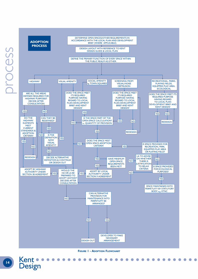
Developers and Authorities involved in the process of adoption shouldtake a holistic approach to the process to ensure ALL spaces in thepublic realm are maintained for the lifetime of the development.
If not all the spaces can be formally adopted then alternativearrangements must be put in place for the spaces to be maintainedfor the lifetime of the development, or they should be designed out.
In order to determine how all the areas are to be maintained, everyspace within the public realm should be given a defined primaryfunction.
Once the primary function for each of the spaces has been defined,then steps can be taken to decide how the space is to be maintainedfor the lifetime of the development through adoption or alternativearrangements.
This outlined policy approach will be underpinned by detailedadoption criteria for both open space and highway elements of aproposal.
Alternative provision for maintenance for the lifetime of thedevelopment may take many forms ranging from the setting up ofmanagement companies to dedicating land to Parish Councils.
Commuted sums are likely to be required for the long termmaintenance of open space, landscape/amenity areas including vergesand all structures including public art. These will be dependant on thespecific adoption criteria of each authority.
The flowchart demonstrates a process which if followed, wouldensure all spaces have a function and that no spaces are left withouta maintenance provision put in place.
The nature of the flowchart encourages a development teamapproach to the issue of adoption and long term maintenance.
Specific open space adoption criteria are to be defined by individuallocal authorities but general principles might include: safetyconsiderations; standard of work; ease of maintenance.
proc
ess
13A G U I D E T O S U S T A I N A B L E D E V E L O P M E N T
KentDesign
proc
ess
14 KentDesign
DETERMINE OPEN SPACES/OTHER REQUIREMENTS INACCORDANCE WITH THE LOCAL PLAN AND DEVELOPMENT
BRIEF (WHERE APPLICABLE)
SCREENING FROMVISUAL/NOISEOBTRUSION
RECREATIONAL, PARKS,PLAYING FIELDS,
EQUIPPED PLAY AREA,ECOLOGICAL
IS SPACE PROVIDED FORRECREATION, PARK,
EQUIPPED PLAY AREAOR PLAYING FIELD?
HAVE MINIMUMOPEN SPACE
REQUIREMENTSBEEN MET?
LA TO ADVISEON WHETHER
THERE ISJUSTIFICATION
TO RELAXCRITERIA
IS SPACE PROVIDEDFOR ECOLOGICAL
PURPOSES?
SPACE MAINTAINED INTOPERPETUITY BY STATUTORY
BODY e.g. KTNC
DOES THE SPACE MEET ITSREQUIRED PURPOSE
HAVING REGARDTO LOCAL PLAN
DEVELOPMENT BRIEF ANDKENT DESIGN?
ARE ALL THE AREASDEFINED REQUIRED FOR
HIGHWAY PURPOSES?DECIDE AFTER
CONSULTATION
DO THEHIGHWAYELEMENTS
MEETCURRENT
STANDARDS &ADOPTIONCRITERIA?
DOES THE SPACE MEETITS REQUIRED
PURPOSE HAVINGREGARD TO LOCAL
PLAN DEVELOPMENTBRIEF AND KENT
DESIGN?
DOES THE SPACE MEETITS REQUIRED
PURPOSE HAVINGREGARD TO LOCAL
PLAN DEVELOPMENTBRIEF AND KENT
DESIGN?
DEFINE THE PRIMARY FUNCTION OF EVERY SPACE WITHINTHE PUBLIC REALM AS EITHER:
SOCIAL AMENITYeg TOWN SQUARES
CAN THEY BEREDEFINED?
ADOPTIONPROCESS
IS THE SPACE PART OF THEOPEN SPACE CALCULATION?i.e. QUANTITY OF PROVISION
DOES THE SPACE MEETOPEN SPACE ADOPTION
CRITERIA?
ADOPT BY HIGHWAYAUTHORITY UNDER
SECTION 38 AGREEMENT
DECIDE ALTERNATIVEDEFINITION & CONTINUE
OR DESIGN OUT
IS THEDEFINITION
NOWVISUAL
AMENITY?
WOULD THE HA OR LA BE
PREPARED TOADOPT ANYWAY?DECIDES AFTERCONSULTATION
CAN ALTERNATIVEPROVISION FOR
MAINTENANCE INTOPERPETUITY BE
ARRANGED?
DEVELOPER TO MAKENECESSARY
ARRANGEMENT
ADOPT BY LOCALAUTHORITY UNDER
SECTION 9 AGREEMENT
DESIGN LAYOUT WITH REFERENCE TO KENTDESIGN GUIDE & LOCAL PLAN
HIGHWAY VISUAL AMENITY
REDESIGN
REDESIGN
DESIGN OUT
REDESIGN
YES
YES
YES YES
YES
YES
YES
YES NO
NONO
NO
NO
NO
NO
NO
NO
NO
YES
YES
YES
YES
YES
YES
NO
NO
NO
YES
FIGURE 1 - ADOPTION FLOWCHART

1.2.2 ADOPTION POLICY
HIGHWAYS
The Highway Authority will adopt areas that are required for the useand maintenance of the highway, and will consider other associatedareas for adoption in consultation with individual local authorities,which may require the payment of commuted sums.
The Highway Authority will only adopt Commercial and IndustrialRoads where there is clear benefit to the general public and whereunits are in individual ownership.
Adopted carriageways, footways, footpaths and cycleways mustconnect to another highway maintained at the public expense.
All accesses serving more than 5 dwellings should be laid out toadoption standards.
Developers must prove ownership of all land to be transferred prior toadoption by the Highway Authority. In situations where land is in“unknown ownership” the Highway Authority will require Developersto provide adequate Defective Title Indemnity Insurance which mustbe in place prior to the Section 38 Agreement being signed.
Footways, Footpaths and Cycleways will be adopted where theyprovide the primary means of pedestrian access to buildings or are anessential part of the highway system in so far as it relates to themovement of pedestrians and cyclists.
If the number of dwellings served by a cul-de-sac exceeds 50 orwhere a major access road is designed as a circuit road, then analternative means of access for cyclists and pedestrians, which couldalso be used for vehicular access in the event of an emergency, maybe required. Alternative means of access will be adopted by theHighway Authority.
All adoptable areas and structures will, as a minimum, meet theobjectives of Kent Design and current highway design standards asadopted by KCC.
All adoptable areas will be clearly identifiable on site and anydelineation will be sympathetic to the locality.
Means of access for future inspection and maintenance must bedetermined prior to agreeing adoptable areas.
1.2.2.2 SERVICES
Private services (excluding service connections) will not be located inadoptable areas, except in exceptional circumstances when theymust be covered by a licence under Section 50 of the New Roads andStreetworks Act 1991.
The Developer is to ensure that all new roads are pre-ducted toaccept cable television by direct liaison with the Cable FranchiseCompany. The Highway Authority will not adopt a road which hasnot been pre-ducted unless it is confirmed in writing by the CableFranchise Company that they do not intend to supply the cablenetwork to the development.
1.2.2.3 LANDSCAPING
The Highway Authority will adopt landscaped areas and verges thatare required for highway purposes, such as visibility splays andservice strips.
Areas between a carriageway and a footway or cycleway will beadopted if they are required for highway purposes. If these areas arenot required for highway purposes they will be adopted if acommuted sum is paid to the highway authority based on maintainingthe area for the lifetime of the development.
If an area is not offered up for highway adoption with a commutedsum, then developers must provide or arrange for the long termmanagement of all unadopted landscape areas and verges through a
management company or similar. Section 9 of the Open Spaces Act1906 enables amenity areas to be maintained by the District Council.
1.2.2.4 PARKING AREAS AND LAYBYS
Only lay-bys and parking areas provided as an integral part of thehighway for casual parking will be adopted.
Private parking areas must be located outside the adoptable highwaylimits.
1.2.2.5 STREET LIGHTING
The Highway Authority will only adopt road lighting situated withinadoptable areas, except where specific alternative arrangementshave been approved and these must be covered by a Deed of Grant.
The local Parish or Town Council must be consulted over whetherthe provision of street lighting in a development is acceptable,particularly if the location has no street lighting.
1.2.2.6 HIGHWAY DRAINAGE
The Highway Authority will adopt drains (pipework, gullies, manholes,catchpits and soakaways - but excluding pumping stations) laid for thesole purpose of the discharge of surface water from the highway.
Highway drainage will be laid within adoptable areas with thepossible exception of soakaways which must be subject to a deed ofgrant to enable access for future maintenance.
Combined sewers, draining foul and surface water, and surface watersewers draining rainwater from building, yards etc, should beadopted by the Drainage Undertaker.
Where a sewer is laid within the proposed highway, or where asewer accepts water from a proposed highway, and that sewer is thesubject of a Section 104 Agreement under the Water Industry Act1991, then the Part II certificate will not be issued until a provisionalcertificate has been issued by the Drainage Undertaker for the workswhich are the subject of the 104 Agreement.
Soakaways that require licences for ‘consent to discharge’ under theEA`s “Policy and Practice for the Protection of Ground Water” willnot be adopted until the Developer has paid to the County Councilall commuted sums necessary to cover annual charges incurred bythe Highway Authority.
All Soakaways, including those that require ‘consent to discharge’licences from the EA, will not be adopted until the developer has paidto the Highway Authority all commuted sums which are necessary tocover future maintenance. These sums will vary depending on theenvironmental circumstances and location of each Soakawaytogether with the actual type of Soakaway constructed.
1.2.2.7 HIGHWAY STRUCTURES
The Highway Authority will only consider adopting those Structuresdefined in clause 1.1.5.2 that either carry the highway or support it.
Any structure spanning over a highway will not be adopted unlessthat structure itself carries a highway or forms an integral part of thehighway such as a traffic sign gantry.
The Highway Authority will not adopt walls constructed to supportthe highway, except in agreed exceptional circumstances, as it is theAuthority’s preference for the highway to be supported by banking.
Walls supporting private land adjacent to the highway will not beadopted and such walls must be totally founded on private land.
All structures situated within 3.66m of a highway, or which otherwisemay structurally affect the highway or its support, whether adoptedor not, will be subject to full approval procedure as determined bythe Highway Authority.
proc
ess
15A G U I D E T O S U S T A I N A B L E D E V E L O P M E N T
KentDesign

Any unadopted protrusions over the highway will need the approvalof and be licensed by the highway authority.
Highway structures will not be adopted until the developer has paidall relevant commuted sums and associated fees to the highwayauthority.
1.2.3 ADVANCE PAYMENTS CODE (APC) PROCEDURE
1.2.3.1 GENERAL
The creation of more private streets is to be avoided and this can beachieved by the correct application of the APC procedure (asdetailed in the Highways Act 1980). This is a statutory tool whichprovides for the future making up of private streets. The requiredpractice is for the rigorous application of the APC procedure.
Application of the APC procedure together with the administrationand operational activities of Section 38 Agreement schemes,including adoptions, are carried out by the Highway Units on behalfof the Highway Authority.
All of this activity will be exercised in accordance with this document,Statute and the Highway Authority’s current KENT MODEL formof Section 38 Agreement. No variations to the model agreementwill be permitted without the permission of the Area Manager.
1.2.3.2 HIGHWAYS ACT 1980 SECTION 219 - PAYMENT TO BE MADE BY
OWNERS OF NEW BUILDINGS IN RESPECT OF STREET WORKS.
The following extract from Section 219 of the Highways Act1980 is reproduced for information:-
219 (1) Subject to the provisions of this section, where:
• it is proposed to erect a building for which plans arerequired to be deposited with the local authority inaccordance with building regulations, and
• the building will have a frontage on a private street inwhich the street works authority have power under theprivate street works code to require works to beexecuted or to execute works.
(1) No work shall be done in or for the purpose of erecting thebuilding unless the owner of the land on which it is to be erected ora previous owner thereof has paid to the street works authority, orsecured to the satisfaction of that authority the payment to them of,such sum as may be required under section 220 below in respect ofthe cost of street works in that street.
(2) If work is done in contravention of sub-section (1) above, theowner of the land on which the building is to be erected and, if he is adifferent person, the person undertaking the erection of the building,is guilty of an offence and liable to a fine not exceeding level 3 on thestandard scale and any further contravention in respect of the samebuilding constitutes a new offence and may be punished accordingly.
(3) Where the person undertaking the erection of the building is notthe owner of the land on which it is to be erected and is charged withan offence under sub section (2) above, it shall be a defence for himto prove that he had reasonable grounds for believing that the sumrequired under section 220 below had been paid or secured by theowner of the land in accordance with sub section (1) above.
1.2.3.3 PROCEEDINGS IN RESPECT OF OFFENCES COMMITTED
Proceedings under sub-section (2) above shall not be taken by anyperson other than the street works authority.
1.2.3.4 DEFINITION OF ‘PRIVATE STREET’
Section 203 of the Highways Act 1980 defines a private street.Briefly, this is a street not being a highway maintainable at the publicexpense and includes, for the purpose of the APC procedure, anyland shown as a proposed street on plans deposited with the District
Council seeking either building regulation approval or planningpermission.
1.2.3.5 APC PROCEDURE
Within six weeks of either Building Regulation approval being grantedor an Initial Notice (issued by the NHBC) being received by theDistrict or Medway Council, the Highway Authority shall serve anotice under Section 220 of the Highways Act 1980 specifying theamount to be deposited or secured in respect of the street workscharges for those dwellings for which approval has been granted.
Notices served, payment made or security given are registrable as alocal land charge with the local District Council.
If the Highway Authority has served a Section 220 notice, no workmay be performed to erect the dwelling (including foundations) untilthe sum specified in the Section 220 notice has been deposited orotherwise secured to the satisfaction of the Highway Authority. Anybuilding works commenced before the advance payment is made willresult in enforcement by way of prosecution.
It is usual for Estate Developers to discharge their obligations underthe APC by completing an Agreement with the Highway Authorityunder Section 38 of the Highways Act 1980. Even though it isproposed to complete such an Agreement, it is still an offence tocommence building works (including foundations) before theAgreement is executed.
A Developer who wishes to start building before the Agreement isexecuted should either make a deposit, or provide the necessarysecurity, in accordance with the Section 220 notice. This amount maybe broken down, on request, to cover individual dwellings. Depositsmade in this way will, upon completion of the Agreement, berefunded to the Developer together with all accrued interest.
1.2.3.6 FORM OF SECURITY
The Highways Act 1980 does not specify the form of security to begiven and it is for the street works authority to decide what form thesecurity should take. The Highway Authority has decided that thefollowing securities are acceptable in lieu of a cash deposit:
• Mortgage or second mortgage on the development land.
• Completed Section 38 Agreement.
• A temporary bond. The bond must be in the standardform acceptable to the Highway Authority.
1.2.4 SECTION 38 AGREEMENT OF THE HIGHWAYS ACT 1980
1.2.4.1 PROCEDURE
Where an Estate Developer wishes to complete an Agreement forthe development site under Section 38 of the Highways Act1980, and when detailed planning consent has been granted,applications should be made to the appropriate Highway Unit.
The Developer will need to prove title to the land which will be thesubject of a Section 38 Agreement, or provide Defective TitleIndemnity Insurance and demonstrate a right to discharge surfacewater from the highway to either a water course, existing orproposed public sewer. Where it is proposed to drain the newhighway into a sewer which is to be the subject of a Section 104Agreement of the Water Industry Act 1991, then thatAgreement must be completed with the Drainage Undertaker priorto the completion of the Section 38 Agreement.
In the development of some sites, it will be necessary to alter theexisting public highway and these works may be the subject of a separateAgreement under the provisions of Section 278 of the Highways Act1980. A standard form of such an Agreement is available from either theCounty Councils Legal Secretariat or the Area Manager.
proc
ess
16 KentDesign
The time taken to enter into such an Agreement is likely to belengthy and the developer should take account of this whenprogramming the works.
The Section 38 Agreement will cover neither foul sewers or anylandscape areas which are outside the highway limits to be adoptedby the Highway Authority.
The Highway Authority’s current KENT MODEL form of Section38 Agreement shall be used in all cases. NO variations to the modelagreement will be permitted without the permission of the AreaManager.
1.2.4.2 DRAWINGS REQUIRED
Initially, the following drawings should be submitted in duplicate forapproval:
• A layout plan at 1:500 scale showing proposed adoptionlimits.
• A layout plan at 1:500 scale showing proposed streetlighting together with calculations and data sheets.
• A plan to at least 1:500 scale showing the junctionbetween the proposed highway and the existing publichighway for Stage I safety audit.
In addition, the following drawings will be required in duplicate:
• A location plan, scale 1:1250 or 1:2500, clearly identifyingthe position and extent of the development site.
• A layout plan, scale 1:500, or to a larger scale as may berequired, showing positions of carriageways (includingcarriageway widening), footways, footpaths, servicemargin strips, verges, traffic calming features, highwaystructures, visibility splays, surface water drainage details,positions of dwellings, parking spaces, garages andvehicle crossings, street lighting, street nameplates, treesand planting etc., and defining by spot levels the falls inturning spaces and on private drives.
• A typical cross-section, showing carriageway and footwayspecifications, camber or crossfall gradient, kerb type,bedding and upstand, etc.
• A typical detail of a vehicle crossing and pedestrian crossing.
• Longitudinal sections, showing existing and proposedlevels, gradients, vertical curves, transitions, surface waterand foul drainage, manholes, etc. Pipe and pipe beddingclassifications should also be included on these drawings.
• Cross sections as may be necessary to indicate proposalsfor dealing with areas of cut or fill.
• Other drawings as necessary to detail surface watermanholes, outfall structures, interceptors, soakaways,retaining walls and other highway structures, etc.
All the layout drawings submitted for inclusion in a Section 38Agreement must be coloured as follows:-
• The new works (colour-washed pink).
• Any works which are situated within an adopted publiclymaintainable highway (colour-washed pink and hatchedred).
• All highway surface water drainage items (coloured blue).
• All highway surface water drainage items lying outsidethe limit of the proposed highway (colour-washed blue).
The area of land colour-washed pink will be transferred into theownership of Kent County Council or Medway Council.
Areas of land colour-washed blue must be covered by a drainageeasement.
There will be a need to ensure that all parties are fully conversantwith the boundary of the existing adopted public highway in the area.The Highway Authority’s Highway Information Centre should beconsulted, particularly if the development will be located outside ofthe urban nuclei, for clarification of such highway limits.
After approval, a total of ten copies of the layout plan and six printsof all other drawings will be required to support the Agreement.Additional copies may be required.
For large developments, it is recommended that the layout be dividedinto stages and that separate Agreements be completed for each stage.
1.2.4.3 SEALING OF AGREEMENT
When the detailed proposals have been approved, the drawings will bepassed to the appropriate Legal Officer who will prepare a draftAgreement which will be passed to the Developer’s solicitor forapproval. Once the draft has been approved the engrossment will beprepared and despatched for execution by the parties to the Agreement.
Only when a Developer and his Surety have executed and returnedthe engrossment to the appropriate Legal Officer may building workscommence on the dwellings unless a deposit or security has beenmade. The Agreement will not be revealed on Local Searches until ithas been executed by all parties and completed. Developers areadvised to ensure that any road works undertaken comply with theplan/s approved by the appropriate Highway Unit and that they areinspected by the Unit's representative.
A schedule attached to the Road Agreement will detail theroadworks in two parts.
1.2.4.4 COMPLETION CERTIFICATES, SURETY AND INSPECTION CHARGES
Three Certificates will be issued under the Agreement.
The Part I Certificate On completion of all works comprised inPart I of the Schedule to the Agreement.
The Part II Certificate On completion of all remaining workscomprised in Part II of the Schedule to the Agreement.
The Final Certificate On completion of any remedial works at the end of the Maintenance period specified in the Section 38 Agreement.
The extent of the Sureties obligations under the Agreement will beThe Engineer's total estimated cost of all Works comprised in theAgreement. The sureties obligations will be reduced by 50% of theoriginal surety value upon the issue of the Part I Certificate andreduced by a further 25% of the original surety value upon the issueof the Part II Certificate. The sureties obligations will reduce to nilupon the issue of the Final Certificate. On the issue of the Part IICertificate the road(s) will become highways, open to public use, butmaintained at the developer’s expense. On the issue of the FinalCertificate the road(s) will become maintainable by the HighwayAuthority at the public expense.
If the site is also the subject of a Section 104 Agreement underthe Water Industry Act 1991 and the sewer is situated within thehighway or is an integral part of the highway drainage system, thenthe Part II Certificate will only be issued after a 'ProvisionalCertificate’ has been issued by the Drainage Undertaker for theworks which are the subject of the 104 Agreement.
Landscaping areas to be adopted under the Section 38 Agreementmust be fully established before the Part II Certificate is issued andthe areas shall be maintained weed free by the Developer during themaintenance period and until the Final Certificate is issued.
proc
ess
17A G U I D E T O S U S T A I N A B L E D E V E L O P M E N T
KentDesign

The Final Certificate will only be issued when:
• The transfer of the ‘highway’ land has been completed -that is, the area of land colour-washed pink on theapproved Section 38 drawings.
• All necessary Deeds of Grant for drainage or street lightingsituated outside the highway limits have been completed.
• Landscaping areas that are to be adopted are fullyestablished and planted in accordance with thespecification. If the Developer defaults on the maintenanceaspect and there is a need to re-plant, adoption will bedelayed until the landscaping is fully established oralternatively the developer pays a commuted sum to theHighway Authority so that adequate maintenance can begiven in the early years. If more than 20% of planting hasto be replaced before final adoption, then the developerwill be required to extend his liability for maintenance fora further period to be agreed with the Area Manager.
• A Health and Safety File, as required by theConstruction (Design and Management)Regulations 1994, has been delivered to the AreaManager. The H&S File should include two sets of ‘asconstructed’ drawings and appropriate data for HighwayInventory and Structures Database input.
• All other requirements of the Section 38 Agreement havebeen fully complied with.
The Agreement will provide for the payment to the HighwayAuthority of costs associated with the works and these will bedetailed in the Agreement. Additional commuted sums will benecessary for the future maintenance of adopted highway structures.
The Agreement will contain a clause stating that no dwelling shall beoccupied until all works specified in Part I of the schedule to theAgreement up to and including the frontage of the property inquestion and connecting it to a highway maintainable at publicexpense have been completed and approved. In some circumstances,the connecting road may itself be subject to a Section 38 Agreement.
1.3 A SUSTAINABLE APPROACH TO HIGHWAYSCONSTRUCTION
1.3.1 INTRODUCTION
Developers should be aware that the Highway Authority iscommitted to the implementation of sustainable solutions whereverit is possible to include them economically and viably, withoutcompromising unduly the quality of the finished works.
The standards for the pavement thicknesses and the choice ofmaterials detailed in Kent Design are indicative of the minimumstandards that will be acceptable to the Highway Authority.
Developers should demonstrate their commitment towardssustainability by considering alternative construction materials, whichsatisfy the principles of sustainability shown below, but retain similarperformances to those of more traditional materials. Each site willhave its own individual characteristics which will need to be evaluatedaccordingly. Evidence of this evaluation should be provided.
Techniques to conserve resources and the use of recycled materialsare developing rapidly as they become more competitive.Consequently more and more public authorities are demanding thatsustainability issues are addressed positively and constructively.
Kent County Council now has a committed approach to sustainablesolutions and can provide an approval process that includes atechnical assessment of the re-used or recycled product and themethod of recycling, together with laboratory appraisals and fieldtrials where necessary.
The approval process and any relevant specification required willonly be provided at the developer’s expense. Specifications can beproduced where required for specific development needs andcontract control purposes
There are a number of Kent specific clauses denoted by the suffix AK.These are additional to those within Volume 1 of the HighwaysAgency’s Manual of Control Documents for the Highway Works, andcan be obtained from Kent County Council.
1.3.1.1 PRINCIPLES OF SUSTAINABILITY
Sustainability is concerned with conservation of resources. Inengineering terms this could be achieved in the following ways:-
• Minimising of Materials.
• Reduction of Waste.
• Recovery of Materials for re-use.
• Re-use and Recycling of Materials.proc
ess
18 KentDesign
TABLE 1: PRINCIPLES OF SUSTAINABILITY
Minimising of Materials Use only the minimum materials necessary for the development and, where practicable,the thinnest pavement design of the available permitted options. (see notes a)
Reduction of Waste Developers can effectively reduce the wastage of materials by introducing regular audits to monitor and control site activity more closely, e.g. materials ordering and sitepractices. (see clause 1.3.3)
Recovery of Materials Where any site clearance or demolition is for Re-Use involved, the developer should initially
maximise the recovery and re-use of any materials within the confines of the site or alternatively off-site. (see note d)
Re-Use and Recycling Acceptable methods of recycling include:- of Materials cold processing on or off-site and hot
processing off-site. (see notes e - i)
Notes on Table 1
(a) Kent Pavement Design Guide includes ‘Asphalt Substitution’ which may be usedto reduce the sub-base thickness.
(b) Kent County Council’s Standard Specification which augments the Specificationcontains additional or revised clauses to assist contractors to implement sustainablealternatives as described in Para 1.3.6.
(c) Pozzolanic (hydraulic bound) materials e.g. Phosphoric Slag in accordance withClause 886 AK, consist of re-used industrial waste products or incorporate binderssuch as slag or Pulverised Fuel Ash (PFA) which are industrial waste products. Benefitsresulting from their use include the reduction of the total quantities of materialsneeded on site and savings on transportation costs.
(d) Acceptable materials for re-use include kerbs, channels, gully grates and pots,manhole and inspection covers, which are of equivalent specification, in good orderand appropriate for the location. Other street furniture may also be consideredacceptable by the Engineer.
(e) In-situ processing techniques are considered more environmentally friendly. Theycan also increase operational speeds on site, reduce local traffic congestion andtransportation costs. Services to carry this out are widely available from specialistcontractors. Consideration shall be given for the potential effects of noise and dustproduced by the processes.
(f) Cold processing on site, in accordance with Clauses 614, 615 and 994 AK may beused to improve the road foundation and reduce or even eliminate the need forimported granular material.
(g) Cold processing on site methods, in accordance with Clause 994 AK and Clause1086 AK, can be carried out on existing materials or on demolition materials, planingsor other imported materials to produce structural pavement layers. They can be usedin a wide range of carriageway and footway locations.
(h) Cold processing off-site produces materials which, when combined with bitumen,bitumen emulsion and other binders, can be used as road base layers on mostresidential access roads and distributor roads, in accordance with Clause 996 AK.
(i) Hot processing off-site, in accordance with Clause 902 or a modified clause subjectto the Engineer’s approval, produces new bitumen bound materials which can be usedin place of materials with no recycled materials content.

1.3.2 SUSTAINABILITY ACTION PLANS
Developers may plan to re-use materials by detailing their intentionsfor waste minimisation and re-use in sustainability action plans. Thisshould cover all the materials used in the construction of thedevelopment including that used for construction of roads andfootways, buildings and especially their fitting out.
Sustainability Action Plans in particular should identify materials usedin high volumes irrespective of cost and materials of high valueirrespective of quantity. These categories of materials are likely toshow the maximum benefit from being targeted for wasteminimisation and recycling.
The subjects to be covered in Sustainability Action Plans may include:
• Who in the organisation is responsible for managingsustainability in the contract
• Details of the training he or she has received
• How information on sustainability is to be conveyed tostaff working on the contract
• How sub-contractors are made aware of, andencouraged to participate in, the sustainability plan.
• What systems are used to control and minimisetransportation, water and energy costs.
• How product suppliers’ packaging e.g. pallets, arerecovered.
• What percentage of recycled materials are contained inthe products you propose to incorporate into the works.
• Which recycling centres will be used for processingmaterials recovered. Are these the nearest centres tothe site. If not, explain.
• Who will carry out waste audits during construction.
• Who is responsible for taking action as a result of thewaste audit.
Studies have shown that it is very beneficial to take positive actionand to give consideration at the planning stage as to how much wastemight be produced on site and what happens to it. In order to assistwith the process developers are encouraged to complete aSustainability Action Plan. A typical questionnaire is shown overleaf fortypical highway materials. Developers may like to prepare one to coverhouse building and fitting out materials, assistance with this may beprovided.
1.3.3 WASTE AUDITS
Developers are also recommended to continue to monitor wasteproduced by a site, especially the two categories of materialsidentified in the Sustainability Action Plan (clause 1.3.2) by carryingout a waste audit as the work proceeds. This has been found to beenlightening both environmentally and financially and helps todevelop a strong commitment by site staff to minimising waste andrecycling that waste which is unavoidable.
The kind of information to be collected is described in theSustainability Awareness Questionnaire.
A system will need to be developed which is site specific but does notgenerate excessive bureaucracy. Assistance with this could be provided.
Waste may be generated on site for the reasons given below. In orderto provide developers and the Engineer with data on which to basefuture requirements and operations and in support of theSustainability Action Plan, the developer is strongly recommended to
supply the results of the waste audit of highway constructionmaterials to the Engineer before adoption of the roads takes place.
The construction of dwellings will potentially generate far morevaluable waste than the construction of carriageways and footways.The principles of sustainability and waste audit are even moreapplicable for this activity.
proc
ess
19A G U I D E T O S U S T A I N A B L E D E V E L O P M E N T
KentDesign

proc
ess
20 KentDesign
SUSTAINABILITY AWARENESS QUESTIONNAIRE
1. What percentage of recycled material is contained in the products we buy?
2. How much of the material required for highway construction can come from the job itself?
3. How much material arising from the earthworks is removed from site?
4. What method is being uesd to make existing sub-grade suitable as a capping layer?
5. Will planings be created as part of the works? If yes what will you do with them?
6. Where is the nearest inert waste recycling centre for arisings?
7. What percentage of product suppliers take back pallets and packaging?
8. Have you identified storage areas for materials to prevent contamination/damage?
9. Who is responsible for managing sustainability on the job?
b. Capping Layer
a. Concrete for Kerbing
Site Name
a. Capping Layer %
b. Sub-base Footway % Carriageway %
Topsoil % Suitable Fill % Other Fill %
Take to asphalt plant Recycling Centre Reuse on site Dump
a. Paving blocks b. Kerbs and Channels c. Ironwork d. Street Furniture e. Others
Job Title Resident on Site
Training received
Topsoil Sub-base Drainage Material Street Furniture
Paving Blocks Ironwork Housebuilding Materials
Kerbs and Channels
c. Sub-base Footway % Carriageway %

1.3.4 REASONS FOR WASTE BEING GENERATED
1.3.4.1 ORDERING TOO MUCH MATERIAL
This may be because of past experience with contamination,inaccurate tolerances on construction layers, risk consequent onhaving too little material and having to order more at higher cost,error in bills of quantities or drawings, mis-ordering.
1.3.4.2 DELIVERY
Products may arrive on site with excess packaging or they may bedamaged during off-loading or storage. Materials may be off-loadedat the wrong location so that during uplifting and moving, some isdamaged, contaminated or wasted.
1.3.4.3 STORAGE
Granular materials; drainage material, sub base, sand bedding and thelike should be stored on a hard base to avoid contamination andwaste. They also benefit from being sheeted to prevent significantmoisture change.
Palletised products need a hard base and ready access for transportto minimise damage
Brittle products like clay/concrete pipes should be protected fromdamage by machinery. Specials and ancillary products need to bestored safely. Electrical equipment and materials that need to be keptdry e.g. cement should be kept under cover.
1.3.4.4 USE AT THE JOBSITE
If a surfeit of materials are laid out at the job site, it is necessary toretrieve the excess and return to store, this is particularly applicableto kerbs and channels and pavers.
1.3.4.5 SEGREGATION OF WASTE
Inert waste may be taken to a recycling centre by skip. It may not beacceptable if it is contaminated with topsoil, plastic, wood, paper,plasterboard and the like. After discussion with the recycling centre,separate skips for recyclable inert waste and the other material couldbe provided.
1.3.4.6 DURING INSTALLATION
Poor installation practices can lead to product/materials damagewhich is unnecessary and could be avoided. It can also lead to anexcess of expensive materials being used. An example is poorpreparation of the sub-base leading to excessive surfacing materialsbeing used. Poor planning can make machine laying of surfacingdifficult, hand laying commonly leads to waste as materials go cold.
1.3.5 INFORMATION CONTAINED IN A WASTE AUDIT
The waste audit should identify those materials that it is worthwhilemonitoring because they are used in large quantities or are of highvalue.
For each product or material identified the following informationcould be collected. It may be prudent to provide this informationregularly to ensure accuracy
• Amount required (No, lin.m, cu.m, tonnes) taken fromcontract documentation
• Amount ordered (From orders placed)
• Amount used (From as-constructed drawings or re-measure if appropriate). This should only be differentfrom bullet point 1 above if a variation has been made tothe works. Excess material e.g. kerb backing, used tofacilitate installation or correct poor tolerance control onthe previous layer is effectively waste
• Volume of inert waste taken to tip
• Volume of inert material taken to recycling centre
• Volume of non-inert waste taken to tip
• Number of pallets delivered, and number returned
1.3.6 ENABLING SPECIFICATION CLAUSES
Specification Clauses which encourage sustainability in carriagewayand footway construction are as follows. Where the Suffix AK is usedthis means that the Clause is published by Kent County Council as anadditional Clause to the Specification. Where the Suffix RK is usedthis means that the Clause is published by Kent County Council as arevision to the Clause in the Specification
1.3.6.1 CEMENT STABILISATION TO FORM CAPPING AND LIME STABILISATION
TO FORM CAPPING
Clause 614 and 615
Commentary: These clauses are used to control the operations ofthe specialist stabilising sub-contractor who will bring to site a largerotavator/pulverisor to mix in the chosen binder. The quantity ofbinder will depend upon the moisture content, plasticity and gradingof the existing soils. Since a large part of the cost is in the mobilisationof the plant it is prudent to plan the roadworks to maximise the workat any one visit.
1.3.6.2 EARTHWORKS ENVIRONMENTAL BUNDS AND LANDSCAPE AREAS
Clause 619 and 620
Commentary: These clauses provide a mechanism for disposing onsite of materials not suitable for road construction, or surplus torequirements. It is usually necessary for the material below thetopsoil and above formation to be removed, this may and should beused within the site wherever possible. The steepness of thesideslopes on landscaping features such as mounds or bunds willdetermine the properties required of the material. The design shouldattempt to allow all the material excavated to be re-used within thesite and the required parameters set accordingly.
1.3.6.3 GRANULAR SUB-BASE TYPE 3
Clause 885AK
Commentary : This clause has been developed in Kent to permit thecontractor to use the output from local recycling centres for inertwaste. It permits small quantities of contaminants such as wood yetproduces a material which is satisfactory for use on footways,cycleways and carriageways on lightly trafficked roads such asHomezones and Minor Access Ways. All materials used must be froma source approved by the Engineer and shall not be frost susceptiblewhen used in the carriageway.
1.3.6.4 PHOSPHORIC SLAG (PERFORMANCE-RELATED MIX)
Clause 886AK
Commentary: Phosphoric Slag is one of a number of hydraulic boundmaterials. It has been used extensively in Kent as an alternativeroadbase/sub-base material. It has the advantages that it may bestockpiled on site for a period prior to laying and compaction, butafter installation sets hard to form a material similar to cement boundmaterial, It sets slowly so there is little likelihood of cracks formingwhich may cause maintenance problems. Initial strength comes fromthe angular nature of the coarse aggregate and very good compactionis essential. Where it is used as roadbase it must also be used as sub-base.
1.3.6.5 RECLAIMED BITUMINOUS MATERIALS
Clause 902RK
Commentary: The Specification limits the amount of recycled asphaltthat can be used in new asphalt. This revision increases the
proc
ess
21A G U I D E T O S U S T A I N A B L E D E V E L O P M E N T
KentDesign

percentage of the maximum practicable through a hot mix plant.There is no evidence that quality is degraded provided that the plantis designed to include this percentage.
1.3.6.6 PERMANENT COLD LAY BASE (PCLB) MATERIAL
Clause 996AK
Commentary: This material is manufactured and may be identical tomaterial which has a Highway Authorities and Utilities Committee(Highway Authorities’ Product Approval Scheme) Certificate forreinstatement material. It is made with a cold bitumen binder and upto 100% recycled aggregates. There is likely to be less waste ordeterioration with material when laying slowly by hand or in confinedareas.
1.3.6.7 GENERAL REQUIREMENTS FOR CEMENT BOUND MATERIALS
Clause 1035
Commentary: Cement Bound Materials are particularly suited tolaying beneath block paving as the inevitable cracks do not causemaintenance problems. However quality control of strength andparticularly compaction in accordance with this clause is vital forperformance
1.3.6.8 OTHER MATERIALS (IN PARTICULAR THE USE OF HYDRAULIC BINDERS
FOR SOIL STABILISATION AND PRODUCTION OF SUB-BASE AND ROADBASE ARE
AVAILABLE ON DEMAND).
Commentary: This is new field for the UK though these materialshave been widely used in France and elsewhere in Europe. They usethe by-products from power generation or metal production toproduce a binder which is cheap and effective with some advantagesover Portland Cement. Specifications are still evolving and contractorsare advised to work with the Engineer using the advice of reputableconsultants and manufacturers when submitting proposals.
1.3.7 REFERENCES FOR IMPLEMENTING SUSTAINABILITY
Environmental assessment - A guide to the identification, evaluation andmitigation of environmental issues in construction schemes SP96 CIRIA
Environmental handbook for building and Civil engineering projectsSP 97-Design and Specification SP98 Construction phase CIRIA
Waste minimisation in construction - SP 134 Design Manual: SP 133 SiteGuide CIRIA 6 Storeys Gate London WSW1P 3AU 0171 222 0445
Digests from the DETR Aggregates Advisory Service on a very widerange of materials and specifications and other sources of information
(AAS Freephone 0800 374 279)
proc
ess
22 KentDesign

desig
n
KentDesign

desig
n2 . D E S I G N
24
2
KentDesign
2.1 HIGHWAY STANDARDS FOR RESIDENTIAL ROADS
When designing new highway infrastructure consideration must begiven to the requirement for greater access to persons with amobility impairment. The term ‘mobility impaired’ encompasses awide range of people, from wheelchair users and the visuallyimpaired with guides/dogs to parents with pushchairs and shopperswith heavy shopping bags. Improving the highway for these roadusers will improve it for all road users.
It is necessary to take into account the aids people use to get aroundwhen designing or improving the highway. A person walking can copewith a narrow footway or a pinch point en route. However, a wheelchairuser or a visually impaired pedestrian guided by a dog cannot.
Kent County Council has produced a code entitled ‘HighwaysSuitable for the Mobility Impaired’ and reference must be madeto this guide in designing highway layouts to ensure the needs of themobility impaired are catered for.
2.1.1 HIGHWAY LAYOUT DESIGN GUIDANCE
The document entitled ‘Housing Estates - Lifting the Quality’produced jointly by the DETR, House Builders Federation andPlanning Officers Society describes the need to reintroduce a varietyof spacial types in highway layout design in order to createappropriate variety and add to a sense of place.
This guide encourages the need for appropriate variety in layoutdesign and considers how the variety of spacial types promoted in‘Lifting the Quality’ can be related to the various road types detailedin table 2. It is considered that the various spacial types can berepresented by differing road types to offer a considerable array ofoptions to the highway layout designer who should be workingclosely with Architects and Urban Designers to produce a ‘place’.
The table below indicates how this guide promotes the use of avariety of spacial types in relation to various road types.
The following illustrations are provided to stimulate a variety ofsolutions appropriate for a particular location rather thanrepresenting a set a prescriptive standards. The illustrationsdeliberately do not show standardised layouts but attempt to indicatehow a highway can be use to create a space and become an integralpart of the overall design for the area.
TABLE 2: STANDARD ROAD AND SPATIAL TYPES
STANDARD ROAD TYPES
STANDARDSPATIALTYPES
STREET ✓ ✓ ✓ ✓ ✓ ✓ ✓
AVENUE ✓ ✓ ✓ ✘ ✘ ✘ ✘
CRESCENT ✘ ✓ ✓ ✓ ✓ ✘ ✘
SQUARE ✘ ✓ ✓ ✓ ✓ ✓ ✓
GREEN ✘ ✘ ✓ ✓ ✓ ✓ ✓
LANE ✘ ✘ ✘ ✓ ✓ ✓ ✓
MEWS ✘ ✘ ✘ ✓ ✓ ✓ ✓
COURTYARD ✘ ✘ ✘ ✘ ✓ ✓ ✓
CULS-DE-SAC ✘ ✘ ✘ ✓ ✓ ✓ ✓
HOME - ZONE ✘ ✘ ✘ ✘ ✘ ✘ ✓
DistrictDistributor7.3m
LocalDistributor6.75m
MajorAccess Rd5.5m
MinorAccess Rd4.8m
MinorAccess Way4.1m
MinorAccess Way3m
Home -Zone

desig
n
25A G U I D E T O S U S T A I N A B L E D E V E L O P M E N T
KentDesign
FIGURE 2 - TOWN CENTRE SCENARIO 1
FIGURE 3 - TOWN CENTRE SCENARIO 2
2.1.3 TOWN CENTRE SCENARIO 2
This alternative town centre scenario indicates how the basic spatialtype of a street is designed to a combination of major and minoraccess road and minor access way standards. The illustration shows
how a junction can be used to meet more than one objective. Theraised junction creates a bus, pedestrian and cycle interchangeserving houses within a 400m radius. The raised junction alsoprovides a means of traffic calming at this multi-modal interchange.
2.1.2 TOWN CENTRE SCENARIO 1
This illustration combines the spacial types of an avenue, a crescent,a square and a street. In this case the illustration indicates the avenueis designed to a local distributor standard, whilst the crescent isdesigned to both major access road and minor access way standards,
varying along its length. The street is designed to major access roadstandards whilst the square is designed to a minor access waystandard. The square shows a trackway running through it, allowingcasual on street parking outside the trackway.

desig
n
26 KentDesign
FIGURE 5 - TOWN EDGE SCENARIO 2
FIGURE 4 - TOWN EDGE SCENARIO 1
2.1.4 TOWN EDGE SCENARIO 1
This example shows a village green incorporating a combination ofstreets and lanes responding to their location and interaction withroutes and buildings. The different types of lanes are designed to
minor access way, minor access road and homezone standards asappropriate to situation. The street acting as the main traffic accessis designed to a major access road standard due to linking the villageto the town centre.
2.1.5 TOWN EDGE SCENARIO 2
The second town edge scenario combines a street, courtyard andsquare homezone. The street is designed to a major access roadstandard with the courtyard access directly off designed to minoraccess way standards. This convergence reacts to the location of thejunction, using it as natural traffic calming by developing the junctionas a multi-purpose node.
These four examples begin to show how a variety of spacial types canbe designed using differing highway standards depending upon the
number, type and disposition of dwellings the highway is serving andthe appropriate target speed required.
The ability to design a variety of spacial types to differing highwaystandards should enable the design team to introduce variety andappropriateness into highway layouts. These should be integral to thewhole scheme’s concept and therefore increase the opportunities forthe individual designers to respond positively and collectively to thelocality in enhancing a sense of place.

desig
n
27A G U I D E T O S U S T A I N A B L E D E V E L O P M E N T
KentDesign
2.2 GEOMETRIC REQUIREMENTS FOR RESIDENTIALROADS
2.2.1 TURNING FACILITIES
2.2.1.1 GENERAL
Turning facilities shall be provided wherever vehicles would otherwisehave to reverse over long distances or whenever they might turn inlocations which could cause damage to adjacent verges or footways.
Depending upon the degree of inconvenience which could becaused, turning areas may be provided as parts of junctions.
The spacing, layout and dimensions of turning areas should bedesigned to cater for the category and size of vehicle normallyexpected to use them. The following criteria however, needs to betaken into account when designing turning areas:
• Refuse and large service vehicles should not be expectedto reverse more than 40m.
• Pantechnicons should not be expected to reverse morethan 60m
• Cars and smaller service vehicles should not be expectedto reverse more than 25m
The siting of turning areas should aim to minimise the likelihood ofvehicles using them for parking. Indiscriminate parking can bediscouraged if the turning area provides direct access into thecurtilage or parking areas of adjacent dwellings. However wherecasual parking is permitted outside the area required for turning,spaces shall be located carefully between driveways as shown in fig 6.
FIGURE 6 - CASUAL PARKING
2.2.1.2 TURNING CONFIGURATIONS
Manoeuvring requirements can be checked by using standardtemplates based on vehicle types expected to visit and use the site.A wide variety of turning movements for various vehicle types aregiven in Appendix 1 of Design Bulletin 32 ‘Residential Roads andFootpaths - Layout Considerations’ 2nd Edition 1992.Designers should use this data to construct the form and size of theturning area best suited to a particular road type. The diagrams givethe minimum envelope required to contain the movement.Nevertheless, consideration shall be give to the tolerances whichmay be necessary, the layout of the road type and the possibility ofkerb overrun and how the area would be swept by mechanicalsweepers.
Manoeuvring requirements can also be checked using one of thewidely available computer software packages currently on themarket. These packages enable designers to generate sweep pathsfor particular vehicle types and to superimpose them onto pre-drafted layout drawings.
2.2.2 GRADIENTS
2.2.2.1 GENERAL
When designing roads there is a tendency to use steep gradients toavoid excessive cut and fill of the natural landscape. However, inorder to minimise the dangers of icy conditions and improve roadsafety on bends and at junctions, there is a need to restrict themaximum acceptable gradients. Similarly to assist in draining the roadand preventing ponding areas, there is a need to restrict theminimum acceptable gradients.
Where changes in gradient occur, vertical curves are required atsummits and sags both for ease and comfort of driving, and at summitsin particular to ensure adequate forward visibility along the carriageway.
2.2.2.2 LONGITUDINAL GRADIENTS
The maximum and minimum longitudinal gradients for residentialroads should be restricted in line with the following recommendations.
MAXIMUM LONGITUDINAL GRADIENTS
• All vehicle, pedestrian and cycle dominatedenvironments, except shared surface environments
6% (1 in 16.7)
• Shared surface environments 7% (1 in 14.3)
MINIMUM LONGITUDINAL GRADIENTS
• All environments (flexible surfacing) 0.8% (1 in 125)
• All environments (block paving surfacing) 1.25% (1 in 80)
Industrial and Commercial Road gradients shall be in accordance withsection 2.3.
Shared and individual private drives shall normally have a longitudinalgradient no steeper than of 10% (1 in 10), however access gradientsmay be increased to a maximum of 12.5% (1 in 8) on sites where thelevel differences make it impractical to use less steep gradients. Toavoid vehicles grounding the gradient should be maintained at 10%(1 in 10) maximum for at least 1.5m from the back of the highwayboundary or include a roll-over detail as shown in Fig 7.
FIGURE 7 - GRADIENTS AND ROLL-OVER DETAILS
ROLL-OVER
WIDTH WIDTH WIDTH

desig
n
28 KentDesign
2.2.2.3 CROSS-SECTIONAL GRADIENT
The carriageway cross-section shall have a profile which is eithercross-fall or cambered, generally at a gradient of 2.5% (1 in 40).
Changes in cross-sectional gradient from cross-fall to camberedshould be avoided where the longitudinal gradient is flat.
2.2.2.4 VERTICAL CURVES
Vertical curves shall be provided at all changes of longitudinal gradientas indicated in fig 8.
FIGURE 8 - VERTICAL CURVES
To ensure reasonable standards of comfort and appearance and tosecure appropriate visibility at summits, vertical curves should beprovided using the following criteria.
The length of curves shall be derived using the formula: L=KA; whereL is the curve length in metres, A is the algebraic difference in gradient(expressed as a percentage) and K has a value as indicated in table 3.
2.2.3 JUNCTIONS
2.2.3.1 GENERAL
Junctions are generally required at the intersection points whereroads meet each other. The majority of junction arrangements takethe form of some type of priority junction, (either ‘T’ types,staggered types or crossroads) which is normally appropriate wheretraffic flows, particularly to and from minor roads, are relatively light.Where flows are heavier or layouts are complex, other types oflayout or control are required to reduce the accident risks and tobalance or improve capacity.
Where a residential road joins a distributor road, a 5.5m width shall bemaintained for 20m from the junction and footways provided on bothsides of the non-priority road. No other road junctions shall bepermitted within this 20m distance including all driveways and accesses.
Junction arrangements involving alterations to the existing highwaywill require the developer to enter into a separate agreement underthe provisions of Section 278 of the Highways Act 1980.
2.2.3.2 TYPES
Junctions involving district distributor or residential local distributorroads shall be designed in accordance with the Design Manual forRoads and Bridges, published by the Department ofTransport, Volume 6 Section 2, TD42/95 or TD16/93
(roundabouts), depending on the traffic flow and turningcharacteristics. Junctions involving industrial and commercial roadsshall be designed in accordance with section 2.3.
Junctions involving all other road types shall be simple ‘T’ typearrangements. Staggered junctions shall be designed in accordancewith the spacing criteria detailed in table 5. Where traffic flows arevery low, for example within minor access ways, consideration maybe given to crossroad type arrangements.
Where non-priority roads, including all connecting roads, serve morethan 100 dwellings the junction with the priority road shall be at an angleof 90º and shall be straight for a length of at least twice the kerb radius.Non-priority roads, including all connecting roads, serving less than 100dwellings can join priority roads at angles between 80º and 100º.
Some junctions involving minor roads, such as shared surfaceaccessways, may require specific entry treatment arrangements inaccordance with section 3.5.
It is recommended that early discussion regarding the junction type,design and location should be held with the Engineer.
2.2.3.3 RADII
Junction radii shall be provided in accordance with table 5. Alldimensions shown in table 5 apply to the priority road.
At junctions where the corner radii is less than 6m the footway shallbe strengthened in accordance with tables 19 and 21.
2.2.3.4 VISIBILITY
To enable drivers emerging from the non-priority road to see andbeen seen by drivers proceeding along the priority roadunobstructed visibility is required within the shaded area shown in fig9, with inter-visibility being provided between heights of 0.6 and 2m.Sags and summits may affect visibility requirements.
FIGURE 9 - VISIBILITY
All junctions will require adequate visibility in accordance with table5. Street lighting columns, sign posts and some trees can be locatedwithin the visibility splays, but larger obstructions shall be avoided asthey could reduce safety levels.
Visibility splays at junctions shall be contained within the adoptablehighway. It is generally desirable for a footway to be set back behindthe visibility splay.
2.2.3.5 GRADIENTS
Gradients should not exceed 5% when rising, or 4% when fallingtowards the priority road for a distance of twice the junction radiimeasured from the channel line of the priority road.
2.2.3.6 RIGHT TURN LANE FACILITIES
Some junctions will require the right turning movements of vehiclesfrom the priority road to be controlled by various methods, whichcan include amongst other things ghost islands, roundabouts andsignal controls.
RTL facilities for local distributors and industrial roads shall be inaccordance with section 2.3.
TABLE 3: K VALUES
Vehicle or Pedestrian and Target Minimum K value Cycle Environment Type Speed for stopping
and adequate comfort
District Distributor Road 30 11Local Distributor RoadIndustrial local Distributor RoadIndustrial Access Road
Major Access Road 25 7
Minor Access Road/Way 20 5
Shared Surface Areas 15 3
Homezones 10 1

All other residential roads will require RTL facilities where thepriority road is a primary or district distributor or where the non-priority road, including all connecting roads, will generate in excess of500 vehicle movements a day.
It is recommended that early discussion regarding the RTL facilitytype, design and location be held with the Engineer.
2.2.3.7 PEDESTRIAN AND CYCLING PROVISION AT JUNCTIONS
All road junctions need to be designed with the safe interests of cyclistsand pedestrians in mind. At busy junctions there may well be a need toprovide separate cycling lanes together with appropriate roadmarkings and signing where space permits, however detailed facilitiesat the junction will depend on location circumstances. If necessaryconsideration should be given to signalling the whole junction.
Pedestrian facilities at junctions may include uncontrolled pedestriancrossing points, refuge islands, zebra or signal controlled crossings. Thedegree of pedestrian facilities required will depend on the nature andvolume of the vehicular and pedestrian movements at the junction.
Defined at-grade zebra or signal controlled pedestrian crossings onminor roads shall normally be set back 15m from the give-way line ofthe junction and should be sited to minimise crossing widths.
Separation islands are normally situated at the mouth of the non-priorityroad. Dropped kerbs and tactile surfacing (at locations along and acrossdistributor roads and where pedestrian flows are likely to be high) shallbe used at all crossing points for the blind and partially sighted.
Guardrails shall be used where significant pedestrian activity makes itnecessary to channel pedestrians to the appropriate crossing point.Care should be taken to ensure that guardrails do not interruptvisibility and consideration shall be given to the type of barrier used.
2.2.3.8 ENTRY TREATMENTS
Entrances to some pedestrian and cycle dominated environments, inparticular shared surfaces, should have visual characteristics thatdefine them from conventional access entrances.
This can be achieved by using design features including granite sets,closely spaced buildings, traffic calming features, ground coverplanting or contrasting paving materials.
It is very important to emphasize to drivers entering shared surfaceenvironments that there is no separate provision for pedestrians. Inthe interests of safety, therefore, it is essential that vehicle speeds arerestrained to 15mph maximum.
2.2.3.9 TRAFFIC SIGNS AND ROAD MARKINGS
Traffic signs and road markings shall be considered as an integral partof the design process. Advanced direction and warning signs may berequired and will depend on the junction layout.
All traffic signs and road markings shall be in accordance with thelatest The Traffic Signs Regulations and General Directions 1994,published by HMSO.
It is recommended that early discussion with the Engineer be heldregarding the need and type of traffic signs and road markings.
2.2.3.10 LANDSCAPING DETAILS
Landscaping can help define the outline of junctions to providereference points and to establish a background for signs. Sensitive useof textured surfaces, choice of street furniture and planting shall beused to enhance the general appearance. Landscaping should notcompromise visibility and good long time maintenance of landscapingmust be taken into consideration.
All landscaping features must be in accordance with the requirementsof section 2.9.
2.3 HIGHWAY STANDARDS FOR INDUSTRIAL ANDCOMMERCIAL ROADS
2.3.1 GENERAL
Industrial and Commercial estates are served by two types of road:
• Industrial Local Distributor
• Industrial Access Road
2.3.2 TYPES
Industrial and Commercial Local Distributor Roads can be defined ashaving the following characteristics:
• a road applicable to all sites on the outskirts of maintowns or infill sites within existing built development.
• a strategic road linking other distributor roads toindustrial access roads, avoiding the residential areas.
• a single carriageway road with a footway, only wherethere is a demonstrable need for pedestrian movement,and a verge on both sides. It shall have either two pointsof access or a single point of access to the districtdistributor whereby a loop type of arrangement iscreated rather than a cul-de-sac.
• a road carrying a high percentage of heavy goods vehicles.
• a road serving in excess of 125,000 m2 of gross floor spaceincluding all adjoining industrial and commercial roads.
• a road that is generally designed to restrain vehiclespeeds to a maximum of 30mph.
• a road that in some circumstances may require theimplementation of a pedestrian refuge to assistpedestrians when crossing busy junctions.
• a road that requires a right turn facility at busy junctionswith district distributors.
• a road that will be generally laid in block paving.
Industrial and Commercial Access Roads can be defined as having thefollowing characteristics:
• a road applicable to all sites on the outskirts of maintowns or infill sites within existing built development.
• a road giving direct vehicular and pedestrian access toindividual premises and linking them to distributor roads.
• a single carriageway through road or cul-de-sac withfootways, only where there is a demonstrable need forpedestrian movement, and verges on both sides.
• a road carrying a high percentage of heavy goods vehicles.
• a road serving up to but not more than 125,000m2 ofgross floor space from the adjoining premises.
• a road that is generally designed to restrain vehiclespeeds to a maximum of 30mph.
• a cul-de-sac road that is normally less than 200m in length.If there is a need to avoid sterilisation of land for exampleconsideration may be given for the cul-de-sac to beextended up to a maximum of 400m in length, but onlywhere full turning facilities are provided at 200m spacing.
• a road that will be generally laid in block paving.
desig
n
29A G U I D E T O S U S T A I N A B L E D E V E L O P M E N T
KentDesign

2.3.3 GEOMETRIC REQUIREMENTS
2.3.3.1 SPEED RESTRAINT
Vehicle speeds on industrial and commercial roads should berestrained to the design target speeds by the use of horizontaldeflection. This can be achieved using the following criteria:
• distances between speed restraint devices shall not begreater than 150m.
• centre line radii for speed attenuation curves shall be nogreater than 40m.
• the length of the separating straight between attenuationcurves of opposite hand shall be no greater then 24m
2.3.3.2 JUNCTIONS
Junction arrangements involving industrial and commercial localdistributor and access roads shall be designed in accordance with thefollowing criteria:
• layout configurations between industrial and commerciallocal distributor roads and primary distributor roads willdepend on traffic flow and turning proportions. Detailsshall be in accordance with the requirements of theDesign Manual for Roads and Bridges, published by theDETR Volume 6 TD42/95 or TD 16/93 (roundabouts).
• layout configurations between industrial and commercialaccess roads and local distributor roads or other vehicledominated environments shall be simple ‘T’ junctions.
• minimum spacing between road centre-lines at junctionswill be as follows:
• 90m - for side roads which join the priority road on the same side
• 15m - for side roads which join the priority road onopposite sides where there is a right-left stagger
• 40m - for side roads which join the priority road on opposite sides where there is a left-right stagger
• It is recommended that right-left stagger junctionarrangements be used instead of left-right arrangementsin order to reduce vehicle conflict.
2.3.3.3 RADII
Radii for junction arrangements involving both industrial andcommercial local distributor and access roads shall be in accordancewith the following criteria:
• 15m - minimum required for all corners and accessentrances.
• tapered kerb lengths equal to 1 in10 (10%) are requiredimmediately after the tangent points of the radii:
• along the near side of the non-priority road for vehicles exiting the priority road
• along the near side of the priority road for vehicles exiting the non-priority road
• footway construction around corners shall be strengthenedin accordance with tables 19 and 21 in section 3.7.
2.3.3.4 RIGHT TURN FACILITIES
A right turning facility is required where the non-priority road type is:
• an industrial or commercial local distributor
• an industrial or commercial access road which serves morethan 15,000m2 of gross floor space, and the priority road is
either a primary distributor or industrial distributor.
2.3.3.5 VISIBILITY
To ensure that drivers of vehicles can both see and been seen byother drivers at junctions, around bends and at entrances topremises, unobstructed visibility is required as follows:
Inter-visibility must be provided between 1.05 and 2m.
Junction visibility shall be provided in accordance with the followingrequirements:
• ‘X’ distance - 4.5m
• ‘Y’ distance - 70m
Where traffic flows are expected to exceed 300 vehicle movementsper hour the ‘x’ distance should be increased to 9m.
Where the priority road is an existing road the ‘Y’ distance shallrelate to the existing measured 85 percentile wet weather speed onthe priority road. Advice relating to wet weather speeds and visibilityis set out in Planning Policy Guidance PPG 13 and DesignBulletin 32. All ‘Y’ distances relating to existing roads shall not beless than 70m.
Visibility around bends is related to vehicle stopping distances and shallbe determined in accordance with the criteria set out in DesignBulletin 32.
Visibility at all vehicular accesses shall be provided in accordance withthe following requirements:
• ‘X’ distance - 2m
• ‘Y’ distance - 70m
Where speed restraint measures are introduced along the road the‘Y’ distance can be reduced to 60m.
2.3.3.6 CARRIAGEWAY WIDTHS
A carriageway width of 7.3m is required for both industrial andcommercial local distributor and access roads. Widening aroundbends shall be in accordance with criteria set out in ‘Designing forDeliveries’ published by the Freight Transport Association.
2.3.3.7 CENTRE LINE RADII
A minimum centre line radius of 40m is required for both industrialand commercial local distributor and access roads.
2.3.3.8 GRADIENTS
• Longitudinal Gradients
Both industrial and commercial local distributor and access roads shallhave a maximum longitudinal gradient of 6% (1 in 16.7) and aminimum longitudinal gradient of 1.25% (1 in 80), except at junctions.
• Junction Gradients
At junctions the gradient shall not exceed 5% (1 in 20) when risingand 4% (1 in 25) when falling towards the priority road for a distanceequal to twice the junction radii measured from the line of thepriority road.
• Cross-Sectional Gradient.
Both industrial and commercial local distributor and access roadsshall have a cross-sectional gradient of 2.5% (1 in 40). Changes incross-sectional gradient from crossfall to cambered should beavoided where the longitudinal gradient is flat.
• Vertical Curves.
Vertical curves should be provided at summit and sag points for allchanges of gradient in accordance with section 2.2.2.4.
desig
n
30 KentDesign

2.3.3.9 TURNING FACILITIES
The manoeuvrability of large goods vehicles depends on their size, onwhether they are rigid bodied or articulated, on the number of axlesand on the skill and judgement of the driver.
Some industrial and commercial estates may have to cater for awhole range of vehicle types and sizes, however in terms ofsustainability it is both impractical and uneconomical to provideturning facilities to cope with the worst of all possible operatingconditions, such as high numbers of the largest vehicles all requiringto visit a site in the same short space of time.
Nevertheless, designs should take into account commonly occurringmovements, recognising that a small number of larger vehicles willoccasionally experience some difficulty in manoeuvring and thatindividual vehicle performance varies greatly with axle configurationand spacing.
Manoeuvring requirements can be checked using two methods. Thefirst is to use standard templates, based on vehicle types expected tovisit and use the site together with design techniques originallydeveloped by the Freight Transport Association. The templates areincluded in the Freight Transport Association document entitled‘Designing for Deliveries’. A second method is to use one of thecomputer software packages available, either to generate the sweptpath for a particular vehicle type or to superimpose it on a pre-draftedlayout drawing. Additional information regarding the characteristics ofturning manoeuvres are described in Design Bulletin 32.
Industrial and commercial local distributor and access roads that arenot through roads or exceed 200m in length without a junction mustalways include a suitable turning facility.
2.3.4 ADDITIONAL REQUIREMENTS FOR INDUSTRIAL ANDCOMMERCIAL ROADS
2.3.4.1 FOOTWAYS
Where there is a demonstrable need to provide access forpedestrians, 2m wide footways shall be provided on each side of theroad for both industrial and commercial local distributor and accessroads. If no development is planned for one side of the road thefootway may be replaced by a 1m wide safety margin planted inaccordance with section 2.9.
If public transport is expected to use the roads the footway adjacentto bus stops and shelters should be widened to 3m.
Footway construction shall be in accordance with tables 19 and 21 insection 3.7 except that an additional 100mm of roadbase shall beprovided.
Longitudinal gradients shall be no steeper than 6% (1 in 16.7). Stepsshould be avoided as much as possible but where it is impossible dueto the topography of the site details should be in accordance withguidance given in the County Council`s Code of Practice “HighwaysSuitable for the Mobility Impaired”.
Cross-sectional gradients should be 2.5% (1 in 40) and shall falltowards the carriageway.
2.3.4.2 VEHICULAR CROSSING POINTS
Direct vehicular access is only permitted off industrial andcommercial access roads. No direct access shall be permitted fromindustrial and commercial local distributor roads.
Vehicular access to units and premises shall not be permitted within20m of the junction of a priority road.
The layout design needs to take into account the necessary widths of thevehicular accesses which should be able to accommodate all operatingconditions. Any large individual premises, say larger than 25,000m2 ofgross floor space, should have its own access at least 6.1m wide.
All vehicular crossings shall be constructed in accordance with table22 in section 3.7.
2.3.4.3 VERGE DETAILS
Verges are required to provide safety barriers for pedestrians wherefootways are provided along industrial and commercial localdistributor and access roads.
Verges shall be 2m wide and provided between the footway and thecarriageway. They shall be planted in accordance with section 2.9.
Verges can be extended to form part of the visibility areas if necessary.
2.3.4.4 PARKING DETAILS
Parking in industrial and commercial developments shall be inaccordance with Kent County Council’s ‘Vehicle ParkingStandards’ published in February 1999 and/or the PlanningAuthority`s local plan requirements.
Security and convenience are important factors for any firm wherevehicles or trailers are likely to be left for long periods, therefore eachindividual unit will require to have sufficient curtilage parking and loadingareas in order to prevent vehicles and trailers being left on the highway.
Special facilities shall be provided for disabled persons or otherspecial needs such as parents with young children, to minimise traveldistances. Parking bay widths shall be designed to accommodateirregular access and ramps or dropped kerbs provided as required.
2.3.4.5 STREET LIGHTING DETAILS
Road lighting shall be provided along all industrial and commerciallocal distributor and access roads in accordance with section 2.8.
2.3.4.6 HEADROOM
Minimum headroom over the highway for industrial and commercial localdistributor and access roads shall be in accordance with the criteria set outin ‘Designing for Deliveries’ published by the Freight Transport Association.
2.3.4.7 VEHICULAR ACCESS TO PREMISES
All private loading and parking areas shall be designed to allow vehiclesto enter and leave in a forward direction. Reversing of large vehiclesonto the highway shall be avoided in all circumstances. All security orgate arrangements shall be sited at least 20m from the highwayboundary in order that parking and administration formalities can beconducted without disturbing other highway users.
2.3.4.8 SURFACE WATER FROM ADJOINING ACCESSES
All private loading and parking areas shall be designed to preventsurface water from adjoining accesses draining onto the highway.
2.4 CYCLEWAY DESIGN
Cyclists need sufficient lateral space to cycle safely and comfortably.Adequate width needs to be provided for the cyclist to progress attheir chosen speed, to overtake other cyclists, to deviate aroundroad defects, debris and other hazards near the kerb and to bepassed safely by motor vehicles. Cycle lanes should be free fromobstructions to allow free passage for cyclists. This includes all typesof street furniture. If any street furniture is in the cycle lanes, enoughwidth must be available to remain at minimum width.
On-carriageway facilities may either be marked as:
Mandatory - a solid white line (Dia 1049) and with flow cycle lanesigns (Dia 958.1 & 959.1). Cycle logo (Dia 1057) can be used whereupright signing is provided.
Advisory - a broken white line (Dia 1004) and sign (Dia 967). Cyclelogo (Dia 1057) can also be used. An advisory lane should only beused where a mandatory cycle lane is unsuitable, such as whenoccasional encroachment by motor vehicles is essential.
desig
n
31A G U I D E T O S U S T A I N A B L E D E V E L O P M E N T
KentDesign

2.4.1 CYCLEWAY STANDARDS
Cycleway Standards are set out in table 4
Widths can be reduced from these desirable levels, only in exceptionalcircumstances. The need to reduce from these levels must bediscussed with the Safety/Cycle Auditor along with supportinginformation on traffic levels, traffic types and cyclist numbers.
If a route is to be segregated, for the safety and comfort ofpedestrians and cyclists all the following must be provided:
• a white delineation line;
• bar tactile markings at the beginning and end;
• blister tactile markings if the route crosses any other roads;
• signs indicating the use of the route.
In order to reduce the possibility of cyclists being squeezed at pinchpoints, it is essential that widths between the kerb and refuge/centralisland are carefully considered:
• Mandatory - 4.5m (1.5m cycleway, 3.0m vehicle running lane)
• Advisory - 4.0m in general (1.2m cycleway)
Where it is expected that cyclists will travel contra-flow with theadjacent traffic flows, segregation shall be provided by means of averge 0.5m wide between the cycleway and the carriageway.
A minimum verge width of 0.5m shall be provided betweencycleways and adjacent buildings.
Cycle parking (preferably covered) shall be provided at key locationsand parking areas where cycles are expected to be left unattended.
Additional guidance for cycleway design is provided in the KCCdocument ‘A Cycling Strategy for Kent’.
2.5 SUMMARY OF THE HIGHWAY STANDARDS
The dimensional standards required in designing a highway layout aredependant upon the nature of the highway and the traffic it is designedto carry. Standards that apply to all highway types are shown in table 5.
desig
n
32 KentDesign
TABLE 4: CYCLEWAY STANDARDS
Cycleway Widths One Way Travel Two Way Travel
Type of Cycleway Desirable Minimum Desirable Minimum
On Carriageway 1.5 1.2 N/A N/A(in addition tocwy width)
Shared with Footway 2.0 1.75 3.0 2.5
Segregated within 3.25 2.7 4.75 3.1Footway (1.5 cyclists, (1.35 cyclists, (3.0 cyclists, (1.75 cyclists,
1.75 peds) 1.35 peds) 1.75 peds) 1.35 peds)

desig
n
33A G U I D E T O S U S T A I N A B L E D E V E L O P M E N T
KentDesign
Road District Local Major Minor Minor Minor Homezone
Type Distributor Distributor Access Road Access Road Access Way Access Way
Type of All Vehicles Low HGVs, Buses Buses, Dustcarts Cars, Dustcarts Cars Only Cars Only Cars Only
traffic Industrial/Commercial Main Traffic Route Occasional HGVs No Buses
Max No of N/A N/A 300 50 25 25 25
Dwellings
Minimum 7.3m 6.75m 5.5m
Width
Trackway 4.8m 4.1m (max 3.0m (with Varies (min
Width road length 60m) passing places) 3.0m)
Shared Surface? No No No No Yes No Yes
Target Speed 30 30 25 20 15 20 15 20 10
Speed Restraint Yes Yes Yes Possibly Possibly Possibly Possibly Possibly Possibly
Required
Max Road Length N/A N/A 80-120 60 40 60 40 60 40
Without Devices
Max Distance 150 150 100 60 40 60 40 60 40
Between Devices
CL Rad for Speed 40 40 30 20 15 20 15 20 15
Attenuation Curves
Max Distance 24 24 20 16 12 16 12 16 12
betw. Att. Curves
Max Dist btwn end Device N/A N/A 100 60(H)-40(V) 60(H)-40(V) 60(H)-40(V)
of cul-de-sac and: Attenuation Curve N/A N/A 50 30 20 30 20 30 20
Junctions “X” Distance 4.5 4.5 2 2 2 2 2 2 2
“Y” Distance 70 70 60 33 23 33 23 33 23
Forward Speed Att Curves 60 60 45 33 23 33 23 33 23
Visibility Speed Cont. Bends 28 28 28 28 23 28 23 28 23
Junction Adjacent 60 60 30
Spacing Oposite R/L 15 15 15
Oposite L/R 30 30 15
Right Turn Facility Yes Yes Yes No No No No No No
Radii 15 10.5 6 4 4 4 4 4 4
Cycleways Yes - Off Cwy Yes - On Cwy Consider shared No No No No No No
(Shared/Segregated) (Mandatory) use with Footway
Fwy Width 2 1.8 1.8 1.8 1.8 1.8
Verge Width 2 2
Margin Width 1.5 1.5 1.5
Casual
On Street Parking No No Yes Yes Yes Yes Yes Yes Yes
Frontager Access No Yes Yes Yes Yes Yes Yes Yes Yes
Street Lighting Yes Yes Yes Yes Yes
Mandatory
Vehicle Dominated Environment Pedestrian and Cycle Dominated Environment
Det
erm
inin
g H
ighw
ay R
equi
rem
ents
Geo
met
ric
Stan
dard
sA
ddit
iona
l Req
uire
men
ts
TABLE 5: CYCLEWAY STANDARDS - HIGHWAY STANDARDS

2.5.1 GUIDANCE FOR THE TABLE OF STANDARDS
The table combines the minimum acceptable standards necessary forhighway layout design and reflects standards that are published inResidential Roads and Footpaths - Layout Considerations -Design Bulletin 32 (Second Edition), published by the DETR.
Interpretation of the standards will rest with the Area Office orDistrict Development Control Officer.
The table differentiates between environments that are dominatedby vehicles and environments where the intention is for them to bedominated by pedestrians and cyclists.
Safety for pedestrians, cyclists and vehicle users is paramount inlayout design and advice must be sought for appropriate level of signsand lines in low speed, pedestrian and cycle friendly environments.
The table describes the type of traffic that is likely to use theparticular road type. The table is split into three sections:
Section 1 determines the basic highway requirements for theparticular road type and the traffic it carries, namely the road widthand target speed;
Section 2 details the geometric standards necessary to achieve thetarget speed and create a safe environment;
Section 3 describes the additional requirements or allowances for theparticular road type.
The Target Speed concept is the context for the geometric standardsand therefore standards are based on road speed not road type.
Lower target speeds of 10 or 15 mph could be used in certain roadtypes and target speeds for certain sites may well be specified in thelocal plan.
Road widths are given for the carriageway in vehicle dominatedenvironments, but are given as the ‘trackway’ width in pedestrianand cycle dominated environments.
Trackways are described in ‘Places, Streets and Movement’,Companion Guide to Design Bulletin 32, Residential Roads andFootpaths, published by the DETR and are the widths that are to bekept clear for traffic within an overall, variable highway width thatcould allow for on-street casual parking or community areas throughwhich slow moving traffic might pass.
There is the need to maintain access for service vehicles toproperties although provision for them should not be the overridingfactor in layout design.
There may be a need to allow access for buses into or adjacent todevelopments although this should not be an overriding factor inlayout design. Narrow widths could be maintained by putting buseson looped routes to avoid them passing each other.
Access for utilities’ works and highways maintenance needs to beconsidered in the layout design.
Major Access Roads can be single carriageway circuit roads (with onepoint of access) or alternatively loop roads (with two points of access).Circuit roads shall have a short connecting length between the circuitand the point of access together with an alternative means of access.
The needs of the emergency services must be taken into account inlayout design. If the number of dwellings served by a cul-de-sacexceeds 50 or where a major access road is designed as a circuit road,then an alternative means of access for cyclists and pedestrians, whichcould also be used for vehicular access in the event of an emergency,may be required. 3m wide access widths must open out to a 3.7mwide envelope to allow for fire appliance doors to fully open.
In narrow roads provided with passing places, care needs to be takenin differentiating them from parking places.
Generally, the developer should be able to demonstrate how a layoutcan work without relying on a prescribed standard for every detail.
In environments where overall highway width varies but a trackwayprovides for movement, casual parking could be allowed in thespaces outside the trackway.
The need for casual parking should be assessed and provided for in thelayout. The provision for casual parking would need to be designed ina way that prevents abuse of the space provided for parking.
Maximum road lengths are introduced as a way of ensuring thatspeeds do not exceed the target speed of the road without the needfor speed restraint. These maximum road lengths would enable alayout to be designed that achieves target speeds without the needfor speed restraint devices.
If road lengths are longer than those stated for the target speed, thenspeed restraint devices would have to be introduced in order toachieve the target speeds.
The table includes standards for junction ‘x’ and ‘y’ distances,junction spacings and radii.
In the third section of the table, footway widths should be based ontheir usage in accordance with the type of road, rather than astandard, but must always remain of sufficient width toaccommodate the mobility impaired and services, as the highwayauthority will not allow services to be provided beneath thecarriageway. Footway widths could be reduced to 1.5m in ruralareas, for example, in keeping with the surrounding location.
Verges are required to separate pedestrians and vehicles in districtand local distributor roads. Margins are only required in sharedsurfaces to accommodate services where a footway is not provided,and for vehicle overhangs where a footway is not provided. Theminimum margin width is 1.5m but this may need to be widenedwhere necessary to accommodate services.
Frontager access is allowed on all road types except for the districtdistributors.
Streetlighting is mandatory on district, local distributor roads andshared surface environments.
2.6 DRAINAGE
2.6.1 DESIGN OF SURFACE WATER DRAINAGE SYSTEMS
2.6.1.1 GENERAL
Surface water from the highway shall be collected by means of gulliesand gully connections, channel and grating systems or combineddrainage and kerb systems and shall be discharged through pipes ofnot less than 150mm diameter to an adequate sewer, highway drain,ditch or watercourse or, where sufficient permeability is obtainable,to soakaways. Where a ditch or watercourse may becomeoverloaded by additional run-off, regulation of the discharge bymeans of a balancing container or pond may be required. The EAshould be consulted regarding outfall and discharge criteria.
Where it is proposed to connect to an existing or proposed publicsewer, the consent of the appropriate Drainage Undertaker will berequired, and the Engineer will require evidence that such consenthas been obtained prior to approving the drainage design.
2.6.1.2 DESIGN OF HIGHWAY DRAINAGE SYSTEM
The ‘Rational (Lloyd-Davies)’ method shall be used for the design ofhighway drainage as set out in Road Note 35 ‘A guide forengineers to the design of storm sewer systems’, published byHMSO and used in conjunction with the ‘Tables for the hydraulicdesign of pipes and sewers (5th Edition)’, published forHydraulics Research by Thomas Telford Ltd, except for smalldevelopments with less than 1000m2 run-off, where a 150mm
desig
n
34 KentDesign

diameter pipe at a minimum gradient of 1/150 will be adequate.
The following parameters shall be used:-
• The system must be capable of accepting without surchargea storm frequency of once every 2 years except for siteswhere consequences of flooding are severe, for example:existing basement properties adjacent to new development,where a frequency of once every 5 years will apply.
• Time of entry - normally 2 minutes.
• Minimum self cleansing velocity - 0.76 m/sec.
• Full bore velocity should generally be limited to 3 m/sec.by the use of back drop manholes or cascades wherenecessary.
• Impermeability factor - 1.0 over whole width of highway(including footways and verges).
• Roughness coefficient of pipes - 0.6mm.
• The following formula shall be used in calculating the rateof flow:
• Q(litres/sec) = 2.78 x R x Ap where R is the rainfall in mm/hr and Ap is the cumulative impermeable area inhectares.
To assist in the checking of drainage calculations a design sheet basedon Table 1 of Road Note 35 should be used, and should besubmitted on ‘A4’ size paper.
Highway drains shall be laid in straight lengths, and within the existingor proposed highway, unless it is impracticable to do so. Under nocircumstances shall chambers be located within carriagewayjunctions or roundabouts. The edge of the excavation should notnormally be closer than 600mm to the proposed kerb line or edge ofcarriageway. Chambers shall be provided at all changes of directionand grade and also at the head of all drains and branches, at everyjunction of two or more drains, except gully connections, and wherethere is a change of size of pipe. The spacing of chambers should notin any case exceed 100 metres. Chambers should not be sited at ornear the centre of the carriageway. A minimum clearance of 150mmshould be maintained where the pipes cross any other piped orducted service and care should be taken to avoid differentialsettlement. Where it is necessary to lay pipes through areas of fill,special precautions shall be taken.
If it should be necessary to lay two pipes, drains or sewers in the sametrench the clear horizontal distance between the barrels shall be 450mmand the proposed chamber details must be submitted for approval bythe Highway Authority and the appropriate Drainage Undertaker.
The basis for design of highway drains up to and including 900mmdiameter, including gully connections and sewers shall be BS 8005.The type and class of both pipe and bedding, which shall bedetermined by the ground conditions, the proposed cover to thepipe, the design loading and the trench width, must be shown on thedrawings. Calculation of design loads and bedding factors shall be inaccordance with the Simplified Table of External Loads onBuried Pipelines, issued by the Building Research Station andpublished by HMSO. All calculations for design loads shall besubmitted for the Engineer's approval.
Highway drains and sewers greater than 900mm diameter areclassified as highway structures and are dealt with under clause 1.1.5.
As far as possible, the pipe cover shall be at least 1.2 metres within thehighway or wherever it may be subject to heavy wheel loads. Elsewherethe minimum cover shall be 0.9 metres. If, at any place, it should beimpossible to provide the cover specified above, the pipe shall be superstrength if a clay pipe or heavy strength if a precast concrete pipe and
surrounded by 150mm thick concrete mix ST2 and provided withflexible joints at no more than 5 metre centres.
Gullies should preferably connect directly into chambers, but if this isnot possible they shall be connected to the main pipe by means of45º oblique angled junctions or be saddled at an oblique angle andsurrounded by concrete mix ST2. Gully connections shall not belonger than 20 metres and there shall be a separate connection foreach gully. Alternatively carrier drains may run directly between eachgully with gully connections serving no more than two gullies.
Each gully shall not drain more than 200m2 of catchment area andgullies shall not be spaced at intervals greater than 45 metres except atsummits where the first gully should not be more than 45 metres fromthe high point. Double gullies shall always be provided at sag points andlow points each with its individual connection to the main sewer.
When calculating areas drained, allowance must be made for all footways,footpaths, paved areas and verges which fall towards the carriageway.
In footpaths separated from carriageways, gullies or channelsconnected to the highway drainage system must be provided wheresurface water would otherwise discharge into adjacent property ordown a flight of stairs.
Gullies should be sited upstream of the tangent point at roadjunctions so that surface water in the channel does not flow acrossthe junction. Care should be taken to avoid ponding in the vicinity ofthe mid-point of the radius kerbs. Where super-elevation is provided,a gully should be sited just short of the point where adverse camberis removed to prevent water in the upstream channel flowing acrossthe carriageway. Care should be taken to avoid ponding in thetransition length when the longitudinal gradient is flat or where thereare traffic islands, central reserves or traffic calming measures. Gulliesmust not be sited directly at pedestrian crossing points, but whereverpractically possible, located directly upstream of the crossing point.
2.6.2 CATCHPITS AND OIL INTERCEPTORS
Catchpits, shall be provided before each soakaway or outfall, inaccordance with drawings referred to in clause 2.5.5. The EA mayalso require the inclusion of oil interceptors and they must beconsulted in all cases concerning such requirements.
2.6.3 PIPES, PIPE TRENCHES, LAYING AND JOINTING PIPES
Vitrified clay pipes and pipeline fittings for highway drains shallcomply with the relevant requirements of BS 65 and be of 'normal'type with flexible mechanical joints. Extra chemically resistant pipesand fittings shall comply with the relevant provision of BS 65.
Unreinforced and reinforced concrete pipes and fittings with flexiblejoints shall comply with the relevant provisions of BS 5911: Part 100.
Ductile iron pipes, fittings and joints shall comply with the relevantprovisions of BS EN 545.
Unplasticized PVC pipes, joints and fittings shall comply with therelevant provisions of BS 4660 or BS 5481. Solid wall concentricexternal rib-reinforced unplasticized PVC sewer pipe shall complywith the relevant provisions of Water Industry Specification No.4-31-05 (published by the Water Research Council).
Pipes shall be spigot and socket, Ogee joints shall not be used. Wherenecessitated by sulphates in the soil, sulphate resistant pipes andconcrete shall be used, the concrete to be compacted to give a densemix, using vibration for all concrete in surrounds to gullies, chambersand the like and in all other cases where practicable. The type andclass of both the pipe and bedding are to be stated on the drawings.
The open end of the last pipe shall be sealed whenever work issuspended using an approved plug to prevent the entry of harmfulmaterial. The end of any pipe to receive a future connection orextension shall be fitted with an approved stopper or seal. Its position
desig
n
35A G U I D E T O S U S T A I N A B L E D E V E L O P M E N T
KentDesign

shall be recorded on a drawing, clearly dimensioned, to be handed tothe Engineer and wherever possible the position shall be suitablymarked on the ground.
The pipe shall not be covered or backfilled until approved by theEngineer. All drains and gully leads shall pass an air test in accordancewith Clause 509 of the Specification.
In addition to the requirements of Clause 509 all highway drains, gullyconnections, and road gullies shall be completely cleaned of alldetritus and foreign matter both at the beginning and end of themaintenance period. If any extraneous matter from the developmentsite enters an existing road drain or public sewer the Developer shallbe responsible for its removal.
2.6.4 GULLIES
Gully pots shall be in accordance with Clause 508 of the Specificationand the following:-
• Gully pots shall be 450mm internal diameter and 900mmdeep with 150mm diameter outlet and manufactured inaccordance with BS 5911 Part 230 or BS EN 295.The outlet shall be fitted with an appropriate trap androdding eye unless agreed otherwise by the Engineer.Alternatively plastic gully pots of approved manufacture,or brick or precast concrete sectional catchpits may beused subject to the approval of the Engineer. Gully potsand sectional catchpits shall be bedded on concrete mixST4 and surrounded with 150mm thickness of concretemix ST2 and shall be connected to the main sewer bymeans of 150mm dia. clay, concrete or UPVC pipes asspecified in clause 2.5.3, bedded and surrounded by150mm thick concrete mix ST2 when the cover to thepipe is less than 1.2 metres, and provided with flexiblejoints at no more than 5 metre centres.
• All gully gratings and frames shall be non-rocking, castiron, to BS EN 124, Class D400 with a 900 cm2
minimum area of waterway, and a minimum frame depthof 150mm. The gratings shall not have longitudinal slotscapable of arresting a cycle wheel.
• Gully frames shall be set on a minimum of 2 andmaximum of 4 courses of Class B Engineering bricks.Engineering bricks to be to BS 3921.
• Gratings and frames to gully pots shall be fixed so thatthe top of the frame is set, initially, slightly below thebasecourse surfacing of the carriageway. They shall bere-set 6mm below the level of the final surface, otherironwork flush with the final surface. Tile slips and thelike shall not be used for adjustment of levels. Gullygratings and frames shall be raised on epoxy mortar.
• Typical gully details are shown on KCC Drawing NosKCC/500/016 to 022 inclusive.
2.6.5 CHAMBERS
Chambers shall be either Manholes, Catchpits or InspectionChambers and shall be in accordance with Clause 507 of theSpecification and the DTp Highway Construction DetailsDrawing Nos F3 and F12, or KCC Drawing Nos KCC/500/006-015 inclusive or Sewers for Adoption fig 1-7 and the following:-
• All chamber, taper and shaft sections are to besurrounded with 150mm of concrete mix ST2.
• All covers and frames shall be cast iron, non rocking, toBS EN 124, Class D400 with a 600mm diameter clearopening and a minimum frame depth of 150mm.
• In some urban areas and in areas liable to flooding the
Engineer may require a larger opening and may have apreference for a different type of cover. In such situationsthe Engineer should be consulted.
• As far as possible, the necessity for backdrop connectionsshould be avoided by lowering the pipe approaching thechamber, but where this is impractical or where it wouldresult in a velocity of flow exceeding 3.0 m/sec., either aproperly constructed backdrop connection or some suitablearrangement to reduce the velocity will be required. Incases of difficulty the Engineer should be consulted.
• In a chamber at a change of size of pipe, the soffit orcrown levels of the two pipes, where conditions permit,should be the same. The soffit level of a smaller pipeshall not be below that of a larger pipe.
• Chambers in fields shall be to the general requirementsof the landowner. Although buried chambers are notnormally acceptable, where these are necessary,approved location marker posts must be provided inagreed positions.
• Chamber covers, frames and other ironwork shall befixed so that the top of the frame is set at the level of thebasecourse surfacing of the carriageway. They shall beset or re-set to the final level prior to the laying of theuppermost surfacing course.
• For Structural Approval of chambers see Section 1.1.5.
2.6.6 SOAKAWAYS
• Soakaways for road drainage should not be used ifsurface water can be disposed by connecting the roaddrains to an existing system or watercourse. Soakawaysmust not be sited in carriageways. For StructuralApproval of Soakaways see Section 1.1.5.
Considerable care must be taken when siting soakaways and thefollowing matters must be taken into consideration:-
• Distance from dwellings, current and future tree planting,carriageways, services, sensitive aquifers, adjacentlandfills/ contaminated land etc,
• Possible future flooding problems,
• Possible future maintenance problems, including currentand future access,
• Need for easements.
• Geological factors including risks of washouts, activationof adjacent solution features and activation of adjacentlandslips.
Highway soakaways shall be situated the following minimum distancesfrom dwellings, (measured from the outside edge of a soakaway):-
• 5 metres for conventional perforated soakaway,
• 10 metres for deep bore soakaway.
• Adjacent soakaways should be spaced a minimum of 10metres apart, otherwise the combined capacity must bereduced to allow for interaction between the soakaways.
Catchpits shall be provided before the connection to a soakaway. Inaddition, the EA may require the inclusion of oil interceptors. In allcases the EA must be consulted. The drainage system shall be jettedand catchpits cleaned out prior to adoption to remove silt generatedduring the construction phase.
The EA's ‘Policy and Practice for the Protection of GroundWater’ includes policy statements on discharges to underground
desig
n
36 KentDesign

strata and should therefore be utilised when considering discharge tosoakaways. Highway drainage to soakaways may be opposed inaquifer protection zones around public water supply boreholes.
An EA ‘consent to discharge' is required to discharge effluent (whichincludes surface water from highways) to controlled waters, whichare defined as inland, coastal and underground waters. It is thereforea requirement of the EA to obtain a 'consent to discharge' licencewhen constructing a soakaway which drains into an aquifer protectedby the aquifer protection policy. The EA should be contacted at thedesign stage of a development if it is proposed to construct highwaysoakaways, to establish whether there is a need for a licence. If the EArequires a licence, then the Highway Authority will require theDeveloper to pay to the Highway Authority prior to the adoption ofthe works, a commuted sum to cover the future costs likely to beincurred by the Highway Authority in paying annual charges to the EA.
The minimum depth of soakaways shall be as to penetrate 2.0 metresinto a suitably permeable stratum for a conventional chamber and 3.0metres for a deep bored soakaway as detailed in Kent CountyCouncil’s ‘The Soakaway Design Guide’. Additional depth may benecessary to give the requisite capacity determined by a comparisonof percolation with storm inflow. Soakage tests shall be carried out asrequired by the Engineer.
Soakaways shall be designed and installed in accordance with KentCounty Council’s ‘The Soakaway Design Guide’, including suchrevisions as may be issued at the time of signing the Agreement.Catchment areas shall not exceed 3500m2 for an individual chamberor bank of interconnected chambers.
It may be necessary to link soakaways with at least 150mm overflowpipes when soakage is poor, and at low points overflow pipes shouldbe provided whenever possible. Alternatively, deep borehole typesoakaways may be considered suitable, subject to EA approval.
The requirements for site investigation for soakaway approvals aredetailed in section 3.2 and in Kent County Council’s ‘The SoakawayDesign Guide’. Falling head soakage tests require approval from theEA and approval in principle by the Highway Authority will berequired prior to the commencement of the construction phase.
Additional site investigation, ground improvement and special designrequirements must be considered where solution features or ‘madeground’ are encountered local to soakaway chambers and inlet pipes.Under these geological conditions design requirements for inlet pipesinclude increased pipe flexibility and increased gradients to allow forfuture differential settlements.
Commuted sums will also be required for future maintenance of eachsoakaway in the soakaway system and will vary dependant upon thetype of soakaway.
2.6.7 DITCHES AND WATERCOURSES
The EA, Inland Drainage Boards and riparian land owners should beconsulted as to whether or not ditches or watercourses ondevelopment sites are to be piped or culverted. Such works requirethe approval of the Local Authority under Section 263 of thePublic Health Act 1936.
Where roads or footpaths are to cross a watercourse or where thepiping of an existing ditch is required, the size of the bridge or culvertmust be agreed with the EA, Inland Drainage Boards and riparian landowners and the Babtie Group (Highways Structures Office).
In the case of a new footbridge over a watercourse theconstructional details should be agreed with the Babtie Group(Highways Structures Office). Persons contemplating anydevelopment involving highway structures are advised to discusstheir proposals initially with the Engineer.
2.6.8 CONNECTION TO SEWERS AND DRAINS
A new highway drain may be connected to an existing surface wateror combined public sewer, or a sewer which is the subject of aSection 104 Agreement under the Water Industry Act 1991,subject to the approval of the Drainage Undertaker, who may wishto make the connection to the existing public sewer. A new highwaydrain may also be connected to an existing highway drain or landdrain, subject to the approval of the Highway Authority and otherrelevant Authorities. In all cases, existing sewers or drains shall beproperly extended, connected and jointed to new sewers, drains orchambers in accordance with Clause 506 of the Specification.
In some cases reinstatement of land drains may be required but,where they are to be connected to a sewer, a catchpit shall beprovided before the connection, having a silt trap 600mm below thelowest pipe invert. In the case of all other drains they shall beconnected in such a way that normal access for the rodding andmaintenance is achieved.
Before entering or breaking into an existing sewer or drain, notice shallbe given to the Drainage Undertaker responsible for the pipe to whichthe connection is to be made and appropriate permission obtained.
Where a new highway drainage system is connected to an existingpiped system a temporary catchpit may be required while the site isbeing developed, the catchpit to be removed on completion of allworks and the chamber to be made good with the necessarychannels and benching.
The removal of detritus from chambers, repairs to defects or re-cleaning of the whole or part of a section will be instructed by theEngineer as additional works where necessary.
2.6.9 OUTFALLS AND HEADWALLS
Where a piped system discharges into an existing ditch orwatercourse the pipe invert shall not be lower than the level of theaverage flow in the ditch or watercourse and under no circumstancesless than 150mm above the ditch or watercourse invert. In all casesthe EA shall be consulted and any of its requirements shall becomplied with.
The end of the pipe shall be directed so as to discharge at an anglenot greater than 60° to the direction of flow in the ditch orwatercourse. The end of the pipe shall be provided with a headwalland apron of a design to support the bank above and adjacent to thepipe and to prevent scouring underneath the pipe. The banks of theditch or watercourse shall be protected from scouring. In all casesthe EA shall be consulted and any of its requirements shall becomplied with.
Furthermore, the construction details shall be agreed by either:-
• The Engineer if the height of the construction is less than1.4 metres, or
• The Babtie Group (Highways Structures Office) if theretained height of the construction is equal to or greaterthan 1.4 metres. (see Section 1.1.5)
2.6.10 DRAINAGE STRUCTURES APPROVAL
Any drainage chamber which has a circular shaft internal diametermore than 1.5m, or a shaft any shape more than 0.9m in width (otherthan circular) together with all pipes greater than 900mm diameterand headwalls greater than 1.4m retained height, will requireTechnical Approval in accordance with the Technical ApprovalProcedure defined in Section 1.1.5.
Approval to any other structure which does not require TechnicalApproval shall be obtained from the Highway Unit, although technicaladvice is available from the Babtie Group (Highways StructuresOffice) if required.
desig
n
37A G U I D E T O S U S T A I N A B L E D E V E L O P M E N T
KentDesign

2.6.11 TRENCH REINSTATEMENTS IN EXISTING HIGHWAYS
It may be necessary to install a new drain within the existing adoptedcarriageway construction. The bed and surround shall be as detailedin Section 2.6.1 and the trench reinstatement shall be in accordancewith KCC drawings KCC/700/001-020 inclusive.
2.6.12 CHANNEL AND GRATING SYSTEMS AND COMBINEDDRAINAGE AND KERB SYSTEMS
In some situations it may be more appropriate to provide channeland grating systems or combined drainage and kerb systems such asBeany blocks or similar. Such systems may be preferable where thelongitudinal gradient is flat and/or at locations where apparatus fromseveral Statutory Undertakers is situated.
Such systems shall be designed in accordance with themanufacturer’s recommendations as well as the criterion set out inSection 2.6.1. The discharge shall be determined so that it can beestablished that the outfall drain has sufficient capacity.
2.7 VEHICLE PARKING GUIDANCE FOR KENT
Vehicle Parking Standards are a crucial element in transport policy,directly affecting the transport operational characteristics of newdevelopment. The first County Council vehicle parking standardswere produced in 1968 and reviewed in 1978 and 1993. Since the lastreview land use characteristics and Government policy have changedand, in February 1998, a revised set of standards were approved forconsultation. These still reflect the need for development to provideparking in accordance with predicted demand.
Subsequent to the commencement of this consultation, in November1998, the Government Office for the South East (GOSE) together withthe Department of the Environment Transport and the Regions(DETR) published a report, for comment, on Parking Standards in theSouth East outside London. This document fundamentally changes thecontext of standards by introducing substantial restrictions. Standardsnow proposed by GOSE are much lower than the County Council’s.
The February 1998 standards were not adopted. However, theCounty Council and the District Councils appreciate the need for anew approach and propose to assess vehicle parking standards in amanner which will ensure that any new proposals are appropriate:
a) to local circumstances,
b) in seeking the efficient use of land within our urban areas, and
c) to making a contribution in reducing costs and environmentally polluting congestion.
As a consequence of the GOSE report the County Council is nowundertaking further research on the implications of the lowerstandards with a view to producing, with the assistance of the 12District Councils in Kent and in combination with Medway Council,new vehicle parking guidance. This research is also likely to benefitfrom an approach currently being worked on by the South EastRegional Planning Conference (SERPLAN) which seeks to develop aparking assessment framework aimed at providing regionalconsistency whilst delivering local flexibility.
As an interim measure, pending the outcome of the new research, anupdated Vehicle Parking Standards document was approved inFebruary 1999 by the County Council. In the document the previousparking standards have been adopted as maximum guidance,rather than minimum standards, and there are no amendments to theactual numerical requirements. The guidance also stresses that alldevelopers should consider the move towards acceptable restraint inparking standards and are advised to enter into discussion with LocalPlanning Authorities at an early stage in their deliberations.
The SERPLAN approach states that with the adoption of maximumguidance in place of minimum standards, the use of commutedpayments (in lieu of parking places) will no longer be a viable tool forraising revenue for funding alternatives. An alternative is thatdevelopers should be expected to contribute towards securingadequate accessibility by all modes of transport, particularly in areaswhere accessibility by non car modes is not adequate.
All references to parking in Kent Design must be read with thisevolving policy context in mind.
2.7.1 STANDARDS
Each dwelling shall have car parking provision provided in accordancewith table 6.
The vehicle parking standards given are maximum guidance ratherthan minimum standards and developers will be expected to considerany opportunities to adopt an acceptable level of restraint in parkingprovision.
Parking standards should be appropriate to local circumstances. Theyshould reflect the need to make efficient use of land, particularlywithin congested urban areas and should be consistent with local andcounty transport policies.
Developers are advised to enter into discussion with Local PlanningAuthorities at an early stage.
For other Land Use Classes, refer to the Kent County Councilsadopted car parking standards, or Local Plan standards if appropriate.
Parking Provision in Industrial and Commercial developments shall bein accordance with the Kent County Council’s adopted car parkingstandards, or Local Plan standards if appropriate.
2.7.2 PARKING PROVISION
2.7.2.1 GENERAL
It will normally be expected that car parking for dwellings will beprovided within the curtilage of each dwelling. However communalparking is acceptable within courts and parking squares.
Car parking provision for individual dwellings shall be provided asdescribed above. For other land use classes, provision shall be inaccordance with KCC’s ‘Vehicle Parking Standards’ or thePlanning Authority ‘s Local Plan standards if appropriate.
Where parking is within the curtilage, end to end garage or parkingspaces shall be restricted to a maximum of two spaces.
desig
n
38 KentDesign
TABLE 6: GUIDANCE FOR PARKING IN RESIDENTIALDEVELOPMENTS
Number of Bedrooms Parking Standardper Dwelling
One One car parking space per unit plus one car space per three units casual, visitor parking
Two or Three One car parking space per unit plus one car space per unit casual, visitor parking.
Four or more Two car parking spaces per unit plus one car space per unit casual, visitor parking.
Sheltered Housing Between one car parking space per unit away from public transport routes, and one car parking space per four units on good public transport routes, plus two spaces for the warden.

Communal parking within Courts and Parking Squares may beallocated within the highway limits, but outside the ‘Trackway’ widthnecessary for the movement of vehicles. Spaces may be allocatedparallel, angled or perpendicular within the court or parking squarebut must be well defined so that adequate access to properties isprovided and indiscriminate parking is avoided.
In Pedestrian and Cycle Dominated Environments communal parkingcan be provided parallel to the kerb by partially widening the road.The trackway width for the road category shall be maintained. Thefootway must be widened by 0.5m adjacent to the parking spaces sothat there is sufficient room for pedestrians to manoeuvre pastalighting passengers. This type of parking arrangement can be used asan effective type of traffic calming feature when well designed.
Parking spaces and facilities for disabled and mobility handicappedpersons shall be provided in accordance with the provisionsdescribed in KCC’s Vehicle Parking Standards’.
2.7.2.2 CURTILAGE PARKING
The design standards for parking spaces within the curtilage shall bein accordance with KCC’s Vehicle Parking Standards.
Residents’ spaces or garages may be located on or near the frontagebut in such a way as not to dominate the street scene. They may alsobe located at the rear of dwellings, either approached between theproperties or from a separate access or drive at the back. All rearparking shall be in secure garages or in areas that are overlooked bythe dwellings to reduce car-related crime.
Disabled and wheelchair users should be able to reach all dwellingswithout the need to negotiate steep ramps and steps.
2.7.2.3 GARAGE AND FORECOURT PARKING
The design of garages shall take into consideration relevant parkingrequirements, however experience has shown that garages are notlikely to be used for the parking of vehicles unless sufficient space isalso incorporated within the garage for storage. Minimum standardswhich allow for an average vehicle and storage space within thegarage are given in KCC’s Vehicle Parking Standards.
Driveways serving garages shall be long enough to accommodatevehicles parked in front of the garage and shall allow sufficient roomfor the garage door to be opened without the vehicle having toproject beyond the curtilage of the property and onto the highway.This length shall preferably be 6m but shall not be less than 5.5m.
Garages that are situated parallel to the carriageway shall be situatedin such a way that vehicles can manoeuvre in and out of the garageadequately from the highway. A minimum distance of 7m betweenthe side of the garage and the carriageway is considered sufficient toallow for all vehicle movements.
2.7.2.4 COMMUNAL PARKING
The design standards for communal parking spaces shall be inaccordance with KCC’s Vehicle Parking Standards.
Where appropriate spaces can be provided on a communal basis. InHomezones and Parking Squares all spaces are likely to be providedin this way. If such spaces are provided then the distance from thedwelling curtilage to the nearest parking space should be 20m or less.Where communal spaces are provided off-street then no more than10 spaces shall normally be grouped together.
All communal parking areas shall be overlooked by the kitchen orliving room windows of at least some dwellings, or footways inregular use to discourage car-related crime.
Where spaces are provided at right angles to the highway the depthof bay shall include a 0.8m planted buffer strip or bollard to preventinterference with highway users as indicated in figs 10 and 11.
FIGURE 10 - PARKING BAY INCLUDING BUFFER STRIP OR BOLLARD
2.8 STREET LIGHTING
2.8.1 ROAD LIGHTING
Road lighting designed to BS 5489 will be provided on all new roadsand footpaths, cycleways and alternative means of access, exceptthose residential access roads in villages and hamlets where theParish or Town Council wish to see it excluded. Alternatively theParish or Town Council may wish to have ‘footway lighting’ installedto their requirements. Such lighting will not be adopted by theHighway Authority but will revert to the ownership of theParish/Town Council.
This exemption will not be allowed on residential shared surfaces,traffic calming devices or shared cycleway/footpath facilities andaccordingly where the Parish or Town Council resist road lighting, thenresidential shared surfaces, traffic calming devices, and sharedcycleway/footway facilities shall not be permitted on the development.
2.8.2 PROCEDURE
It is necessary at the road design stage for the Developer to enquireof the local Highway Unit for its requirements.
The Developer shall provide scale plans of the highway, indicating anyexisting lighting in the vicinity, the height of these columns and thelight source used, together with the location of the proposed newcolumns. The plan shall include, or be accompanied by, a schedule ofthe equipment proposed. In the case of columns this shall includemounting height, material, bracket details and protective finish.Lantern details shall include IP rating, lamps type and wattage, typeand location of control gear, HBC fuse rating and type of photocellcontrol. Where specific manufacturers' equipment is proposed thisshould be indicated with relevant catalogue numbers.
2.8.3 LIGHTING DESIGN PARAMETERS
2.8.3.1 INTER-URBAN PRIMARY OR SECONDARY ROUTES, URBAN PRIMARY OR
DISTRICT LOCAL DISTRIBUTOR ROADS AND INDUSTRIAL AND COMMERCIAL ROADS
Where new road lighting is provided on the above roads it shall bedesigned in accordance with BS 5489 Part 2 to the parameterslisted in Table 7.
desig
n
39A G U I D E T O S U S T A I N A B L E D E V E L O P M E N T
KentDesign

This lighting shall be achieved by use of high pressure sodium lamps(SON-ST)
The choice of system shall be made on the basis of total installation,maintenance and energy costs for thirty years, discounted as appropriateto the current year. Environmental issues should also be considered.
2.8.3.2 RESIDENTIAL LOCAL DISTRIBUTOR ROADS, MAJOR AND MINOR ACCESS
ROADS, SHARED SURFACES, ALTERNATIVE MEANS OF ACCESS, FOOTWAYS,FOOTPATHS AND CYCLEWAYS
Where new road lighting is provided on these roads or majorpedestrian routes, it shall be designed in accordance with BS5489Part 3 to the parameters listed in table 8.
Where traffic calming measures (by virtue of either vertical orhorizontal deflection) are employed, lighting columns should span therestraint at approximately three quarters of the design spacing whereroad geometry allows.
The Developer, if he so chooses, may employ the Babtie Group tocarry out part, or all, of the afore-mentioned design work.
NOTES
• All road lighting shall operate throughout the hours ofdarkness.
• The preferred light sources shall be high pressure sodiumalthough the use of other light sources may be consideredfor special applications, but only used with the specificapproval of the Area Manager. The existence of other lightsources in an area where a new system is installed doesnot preclude the use of high pressure sodium lighting.
• Where, for environmental or other reasons, a Developerwishes to use illuminance levels significantly differentfrom those specified in Tables 7 and 8 these will only bepermitted if the Area Manager is satisfied that thestandard of lighting proposed is adequate and has given itspecific approval.
• Lighting columns, wherever practicable, shall be sited atthe back of footways or verges. New columns shall not besited less than 0.8 metres from the edge of a Carriagewayor hardened edge strip. Where columns are erected inservice strips or verges, all planting shall be kept clear toprevent obstruction of access for maintenance purposes.
• If a Developer wishes to use non standard equipment,departure from this standard will be permitted providedthe Area Manager is satisfied that it is justified and gives itspecific approval.
• Where a road is traffic calmed the Developer shall makereference to the KCC Code of Practice for TrafficCalming.
2.8.4 APPROVAL OF LIGHTING DESIGN
The Developer shall submit for approval to the Highway Unit, twocopies of the layout plan accurately indicating column locationsincluding the set back distance of the column from thekerb/carriageway edge and the bracket outreach, together with allnecessary calculations.
Upon approval of the street lighting design, the Developer shall providethe Highway Unit with three copies of the approved drawing/s.
The exact positions of all lamp columns shall be agreed on site with theEngineer and these will normally be within the highway boundary set atthe back of the footway, service strip or verge. If it is necessary forlanterns to be mounted on buildings or other structures, the Developerwill be responsible for arranging permanent wayleaves at no cost to theHighway Authority and shall inform the Area Manager accordingly.
2.8.5 RESPONSIBILITY FOR MAINTENANCE AND ADOPTION
Before any dwelling or industrial unit is occupied on a new estate, thestreet lighting must be erected and in lighting. The lighting authoritywill accept charges for electricity as soon as the system is approvedand energised.
The Electricity Undertaker will not enter into an agreement with aDeveloper for the supply of energy. The Developer remainsresponsible for the electrical and structural integrity of the streetlighting installation until formal adoption of the lighting system by theHighway Authority or Parish/Town Council.
2.8.6 GENERAL SPECIFICATION
2.8.6.1 DIVERSION AND PROTECTION OF SERVICES
The Developer shall take any and all measures reasonably requiredby any Public Authority or Undertaker for the support and fullprotection of its mains, pipes, cables and other apparatus during theprogress of the works and shall construct and provide to thesatisfaction of the Authority or Undertaker concerned, all worksnecessary for the prevention of damage and interruption of services.
If, in the execution of the works, any damage to any apparatus or anyinterruption of or delay to the provision of any service is caused, the
desig
n
40 KentDesign
TABLE 7: LIGHTING DESIGN PARAMETERS
ROAD AVERAGE OVERALL LONGITUDINAL THRESHOLDTYPE LUMINANANCE UNIFORMITY UNIFORMITY INCREMENT
L (cd/M2) RATIO Uo RATIO UL T.1.
High SpeedRoads 1.5 min 0.4 min 0.7 min 15% maxDualCarriagewayRoads
Important Ruraland UrbanTraffic Routes,Radial Routes, 1.0 min 0.4 min 0.5 min 15% maxDistrictDistributorRoads,IndustrialRoads (throughroad or looproad)
ConnectingRoads,LocalDistributor 0.5 min 0.4 min 0.5 min 30% maxRoads,IndustrialRoads (cul-de-sac)
TABLE 8: LIGHTING DESIGN PARAMETERS
REQUIREMENTS FOR ROAD, VERGE AND FOOTWAYOR FOOTPATH
CATEGORY OF ROAD AVG. MIN. POINTILLUMINANACE ILLUMINANACE
(lux) (lux)
Residential LocalDistributor Roads and 6.0 2.5Major Access Roads
Residential MinorAccess Roads, Shared 3.5 1.0Surfaces and AlternativeMeans of Access

Developer shall bear and pay the cost reasonably incurred by anyAuthority or Undertaker in making good such damage and shall makefull compensation to such Authority or Undertaker for any loss sustainedby reason of such interruption or delay. The Developer shallimmediately notify the owner of the services or property concerned andshall afford every facility to the owner in effecting the necessary repairs.
When working in the vicinity of overhead lines the clearancesrequired by the Electricity Undertaker shall be maintained at alltimes, and fourteen days notice in writing shall be given by theDeveloper to such Authority or Undertaker before commencement.
The Developer shall, at all times during the progress of works, affordfacilities to properly accredited agents of any Public Authority orUndertaker for access to all or any of their apparatus situated in, over orunder the site as may be necessary for inspecting, reporting, maintaining,removing, renewing or altering such apparatus in connection with theconstruction of the works or for any other purpose whatsoever.
The positions of Undertakers mains and services, drains and sewerswhich may be shown on the drawings have been based oninformation extracted from the records of the various bodies andmust be regarded as approximate only. The Developer shall not berelieved of his responsibilities and shall proceed with due cautionwhen excavating in the vicinity of Undertaker's mains and services,drains and sewers.
2.8.6.2 INTERFERENCE WITH TRAFFIC AND ADJOINING PROPERTIES
The Developer shall comply with all statutory regulations and local bye-laws relating to work on highways and shall not unnecessarily orimproperly interfere with access to, or the use, or occupation of, publiclymaintainable highways, footpaths, cycleways and private dwellings.
2.8.6.3 EQUIPMENT AND STORAGE
All equipment shall be supplied in new and unused condition exceptin so far as it has been tested in the course of manufacture and,where deemed necessary by the Engineer, shall be stored inweatherproof accommodation.
The Developer shall ensure that the equipment supplied iscompatible with all other equipment with which it is associated.
2.8.6.4 ELECTRICITY SERVICES
The Developer shall be responsible for all wiring other thanelectricity services which will be provided by the ElectricityUndertaker unless otherwise specified. It shall be the responsibility ofthe Developer to notify the Electricity Undertaker and the Engineerof the earliest date when the installation will be ready for theUndertaker to make the service connection.
2.8.6.5 SWITCHING OFF LIGHTING
No existing lighting shall be switched off, dismantled, resited orremoved without the prior approval of the Engineer and necessaryarrangements having been made with the relevant Undertaker.
2.8.6.6 REGULATIONS, CODES AND SPECIFICATION
All equipment and materials supplied and work done shall comply withStatutory and other Regulations, Codes of Practice, Memoranda andBritish Standard Specifications current at the date of signing the agreement.
2.8.6.7 IDENTIFICATION NUMBERING
Columns shall be identified using an alpha/numeric combination of upto seven digits in accordance with a schedule which will be providedby the Engineer.
The digits shall be shown in black paint not less than 50mm in heightand located in a position 1.8 metres above ground level on a yellowbackground. They shall face in a direction towards the carriageway.
Double arm columns shall have sets of digits on both sides of the column.
2.8.6.8 LANTERNS
Lanterns shall be:
• a type agreed with the Engineer.
• to BS.EN 60598 - 2.3, International ProtectionCategory I.P 65, fitted with vandal resistant bowls andshall be of a uniform pattern from a single manufacturer.
• suitable for the lamp type offered and shall be of the sideentry type unless otherwise required. All lanterns shallbe compatible with the columns on which they are to bemounted.
• designed for integral or remote control gear as agreedwith the Engineer. With integral gear, if the control gearcompartment is provided with its own cover the lattershall be adequately hinged.
• If a separate cover is not fitted to the control gearcompartment the terminal block shall be shielded withsuitable insulating material to prevent contact duringlamp replacement and routine maintenance. The shield isto be captive in that it shall not be necessary tocompletely detach it from the lantern in order tomaintain integral control gear.
• An earth connection is to be provided in the control gearcompartment. When access to this compartment hasbeen attained the earth connection shall be visible andeasily accessible without removing any components.
• suitable for use with high pressure sodium vapour dischargelamps unless otherwise agreed with the Engineer.
• When fixed to brackets providing an uplift, continue theline of the bracket or be mounted horizontally.
• supplied complete with suitable lamp holders readywired to a connector block with flexible cord with noless than 0.75mm2 conductors insulated with non-hygroscopic heat resisting materials.
• have the canopy suitably drilled prior to delivery toreceive the two piece photo-electric control cell unitwhich shall be wired to a terminal block secured to theunderside of the lantern canopy.
• wired between the socket or control unit and theterminal block with colour coded cable.
• not fitted to brackets until after the brackets have been fittedto the columns and the columns erected at the correctvertical alignment unless otherwise agreed by the Engineer.
• snugly attached to the bracket without any gap betweenthe bracket and the root end of the lantern.
• be supplied and protected with packing material toenable reasonable stacking.
2.8.6.9 LAMPS
High pressure sodium vapour lamps shall comply with BS EN 60662.
Lamps shall be suitable for use with the lanterns offered and shall givethe required lumen output at 2000 hours.
High pressure sodium lamps shall have external igniters and shall beof the tubular type unless otherwise specified.
All discharge lamps shall be guaranteed by the manufacturer for aminimum of 4000 hours of life.
Lamps shall not be fitted until the luminaire has been installed on thecolumn.
desig
n
41A G U I D E T O S U S T A I N A B L E D E V E L O P M E N T
KentDesign

2.8.6.10 PHOTO-ELECTRIC CONTROLS
Photo- electric control units (PECU ‘s) shall comply with BS 5972.They shall be designed to switch on when the ambient dusk lightinghas reached 70 lux and have a differential of 1:05. They shall bedesigned so that in the event of a fault occurring in the unit they shallfail safe in the ‘ON’ position.
Photo-electric controls shall be of the two piece unit type as specifiedby the Engineer and set to 70 lux.
2.8.6.11 CONTROL GEAR
• Ballasts
Ballasts shall comply with BS EN 60920, BS EN 60921, BS EN60922 or BS EN 60923 as appropriate.
Terminals for lamp and supply connections on ballasts shall beshrouded and indelibly marked to permanently indicate their function.
• Capacitors
Capacitors shall comply with BS EN 61048 and BS EN 61049 andbe supplied complete with fixing clips, discharge resistors and eithersealed-in cable tails or shrouded terminals.
Capacitors shall correct the lamp circuit power factor to not less than0.85 lagging
• Igniters
Igniters shall be provided where required and shall be suitable for theequipment offered and have shrouded terminals.
• General
Control gear shall be suitable for 230 (+10% or -6%) volt operationunless otherwise specified and be compatible with other equipmentin the circuit, all in accordance with the manufacturer’s instructionsfor the lamp used.
All terminals shall be shrouded to IP2X.
Remote mounted components shall be arranged so that the terminalsare facing downwards and all such components shall be fitted with anearth stud or terminals.
2.8.6.12 FUSES IN BASE COMPARTMENT
Each lamp circuit shall be protected by one of the following methods.
• For secondary isolation on an Electricity Company supplyan isolater unit incorporating a disconnector and a highbreaking capacity type fuse to BS88 rated in accordancewith the lamp manufacturer's recommendations, shall besupplied. This unit which shall be capable of being lockedin the "off" position shall have shrouding or other barrierprovided to prevent contact with live parts affording adegree of protection of at least IP2X and removable onlyby the use of a tool. If there is need to provide a secondcircuit, for example: to a sign, a unit having adisconnector and 2 x BS88 fuses shall be provided.
• Cut-outs, provided for private cabling networks ownedby the Highway Authority shall consist of a substantialmoulded plastic, drip proof enclosure designed primarilyfor use in street lighting columns. They shall provideswitched, double pole isolation by a disconnector andincorporate a high breaking capacity fuse to BS88 ratedin accordance with the lamp manufacturer'srecommendations. They shall be capable of providingone, two or three separately fused upward circuits orone upward circuit and two dedicated double poleoutgoing circuit to sign etc. Terminals shall be largeenough to take the steel wire armoured cable specified
in straight connections or looped services and haveintegral brass cable glands.
2.8.6.13 FIXING CONTROL GEAR
All control gear shall be securely fixed at all fixing points.
2.8.6.14 WIRING
Wiring between the terminal block in the lantern and thecomponents in the base of the column shall be polyvinyl chlorideinsulated and sheathed cable of 300/500 volt grade to BS 6004having a copper conductor size of not less than 2.5 mm2 . All cablesshall be correctly colour coded. Unsupported lengths of wiring shallbe kept to a minimum and not be allowed to come into contact withcomponents by their freedom of movement.
Double insulated 6mm2 tails with inner and outer sheaths of correctcolour coding and sufficient length to reach from the secondaryisolator unit to the service cut-out, must be provided.
2.8.6.15 EARTHING OF COMPONENT PARTS
All metal work other than that intended to carry current shall beearthed using PVC insulated copper cable colour coded green andyellow.
A 2.5mm2 circuit protective conductor shall connect the earthterminal in each luminaire to the earth terminal associated with theservice cut-out unit.
A separate 2.5mm2 circuit protective conductor shall connect allmetal enclosures of all electrical components to the main earthterminal
All extraneous conductive parts, as described in BS 7671 andincluding column doors, shall be bonded to the main earth terminalusing an equipotential bonding conductor of 6mm2.
All earth connections shall be made by means of a crimped lug typetermination.
All terminals are to be shrouded to a value of IP2X
2.8.6.16 ELECTRICAL INSPECTION AND TESTING
• Testing Of New Installations.
The testing and inspection of new installations shall comply fully withclauses 712 and 713 of the 16th Edition of the Wiring Regulations(BS.7671).
A Test and Inspection Certificate in the form set out in Table 9 shallbe completed and submitted to the Engineer.
• Fixed Equipment.
Fixed equipment includes lighting columns, illuminated traffic signs,bollards, feeder pillars and any similar electrical equipment on thehighway, described as street furniture and other street locatedequipment in section 611 of BS.7671.
Tests for equipment shall be in line with the following list and carriedout in the sequence shown:
• Safety Check, Polarity Test and Isolation on Incomingsupply.
• Visual Inspection.
• Insulation resistance test.
• Earth Loop Impedance Test.
• Operation of Residual Current Devices.
• Earth Electrode Resistance.
The tests shall be carried out in accordance with the Testing
desig
n
42 KentDesign

Procedures for Fixed Equipment as detailed below.
• Testing Procedures for Fixed Equipment.
• Safety Check, Polarity Test and Isolation Test on Incoming Supply.
Visually check that it is safe to carry out the tests.
Isolate the internal circuit by removing the fuse carrier/operating isolator
Test the internal circuit to ensure that it has been isolated from all sources of electrical energy.
Carry out Polarity Test at the incoming terminals to confirm that the incoming supply is energised and the Phase, Neutral and Earth conductors are correctly connected.
• Visual Inspection and Fixed Equipment.
The electrical installation shall be visually checked to verify that:
• An isolating/protective device is fitted and that any single pole devices are connected to the phase pole of the circuit only. (For a simple installation the isolating/protective device may be the electricity company fused cut-out).
• Fuses and MCBs are the correct rating.
• Conductors are correctly identified and sleeved accordingly.
• Equipment is visually undamaged.
• Terminations, including earth connections and bonding, are correctly made and secure.
• Power factor correction capacitors are fitted.
• Shrouds, enclosures and doors are securely fitted.
• Labels and danger notices are fitted
• Insulation Resistance of Internal Wiring
An instrument providing a DC test voltage of 500 voltsshall be used for this test and a minimum value of 0.5Megohms is required.
Before any test is carried out it should be confirmed thatthe circuit is isolated from all sources of electrical energy.
• Integral Gear Lanterns:
The neutral should be disconnected from the incoming supply termination unit/cut-out.
The test shall be carried out between L - E and N - E, at the base compartment of the unit.
Poor readings may necessitate the disconnection of the lantern and further test
• Remote Gear Lanterns:
The neutral should be disconnected from the incoming supply termination unit/cut-out
The test shall be carried out between L - E and N - E, at the base compartment of the unit on the tails to the cut-out.
Poor readings may necessitate the disconnection of all connections to the ballast and individual testing of each wiring cable within the column or post.
• Earth Loop Impedance Test - REC Supplies.
This test is to be carried out at the terminals of theincoming electricity company supply to each item offixed equipment.
The purpose of this teat is to ensure that the fuse willoperate within its required disconnection time in theevent of a fault.
desig
n
43A G U I D E T O S U S T A I N A B L E D E V E L O P M E N T
KentDesign
TABLE 9: TEST AND INSPECTION CERTIFICATE
Test and Inspection Certificate - Internal Column / Sign Wiring (Single Phase)
Name (s) of Road (s)................................................................
Column/Sign/ Visual System Circuit Circuit Protection Insulations Resistance Polarity Line/Earth SatisfactoryBollard
Gazetteer ref Inspection Earthing Conduct Fuse MCB Rating (M.Ohms) Satisfactory Fault Loop Unsatisfactoryor
Type Size Bs No Class (Amps) Line to Neutral Line to Impedance Any othermm Earth to Earth Neutral (Ohms) Comments

The test should be carried out using a test instrumentspecifically designed for this purpose.
• Operation of Residual Current Devices
This test should be carried out on any such device usinga test instrument specifically designed for this purpose.
A test should be applied at the rated tripping current ofthe device and the operating time shall not exceed 40msat a residual current of 150 mA.
• Earth Electrode Resistance.
This test is to be carried out in accordance with BS 7430.
• Test Equipment
All test equipment shall be tested and calibrated atregular planned intervals and no item of equipment shallbe used for testing if test and calibration of theinstrument is overdue.
The instrument to be used for polarity and isolationtesting should always be checked before use against aknown 240 volt supply.
2.8.6.17 AS BUILT DRAWINGS
A set of "as built" drawings shall be provided by the Developer for theEngineer upon completion of the street lighting installation. Allcolumn positions and private underground cables installed orrealigned for the works must be accurately recorded on these plans.
2.8.7 EQUIPMENT SPECIFICATION AND INSTALLATION
2.8.7.1 COLUMNS AND BRACKETS
The lighting column manufacturer shall be registered with andcertified by either BSI Quality Assurance Services, Lloyds RegisteredQuality Assurance Ltd, or SGS Yardsley, for the manufacture, supplyand verification of lighting columns under their Quality AssessmentSchedule to BS EN I SO 9000.
Lighting columns and brackets shall be manufactured in compliancewith BS EN 40 Part 1 and BS 5649 parts 2, 3, 5, 6, 7, 8 and 9.
Standard steel columns and bracket arms shall be galvanised andsuitable for the lanterns offered and of a design acceptable to theDesign Council and the Engineer. Columns and brackets shall besupplied by the same manufacturer.
Columns and bracket arms shall together provide a vertical mountingheight measured from the centre of the light source to theCarriageway of 5, 6, 8 or 10 metres, or as agreed with the Engineer.
Columns and bracket arms shall have no sharp or jagged edges whichwould foul or chafe internal wiring.
The compartment in the base of each column shall be designed toaccommodate control equipment of the lamp or lamps and theopening(s) in it shall afford easy access to the equipment. Thecompartment shall be fitted with weatherproof access door(s) havingtamperproof lock(s) of the same pattern for all columns. A total of sixkeys to this lock shall be supplied to the Engineer. Doors shall be fittedwith an earth stud to allow bonding to the main earth terminal. Eachbase compartment shall have a base board manufactured frommaterial which is substantially non-hygroscopic not less than 15mmthick and of suitable size to accommodate the control equipment withadequate space at the bottom to accommodate cable terminationsand service cut-outs. The baseboard shall be firmly fixed.
Where agreed with the Engineer columns shall be fitted with a flangeplate. The Developer shall ensure that the spacing of the flange plateholes and the position of the fixing bolts are compatible.
If manufactured from tubular steel or circular section circumferentialjoints shall be of the sleeve type and restricted to points where thecolumn is designed with reduced diameters. Joints will not beallowed between designed points of reduced diameter.
2.8.7.2 WALL/ POLE BRACKETS AND CONTROL GEAR BOXES
Wall brackets shall be constructed from steel tube and shall providea mounting height of lantern above the carriageway and projectionsas specified. “Projection” is the distance measured horizontally fromthe wall to the end of the bracket. Brackets shall be provided with aback plate of adequate size and strength to permit secure attachmentto buildings and to support the lamp and lantern required and shallbe secure by rag bolts or other approved fixings. The brackets shallbe designed to accept mineral insulated cable glands, when required.
Control Gear Boxes shall be constructed of steel or corrosionresistant alloy and shall be large enough to afford easy access to thecontrol equipment. Doors are to be fitted with tamper-proof locks ofthe same patterns as used for the columns if possible.
A backboard of hardwood or other substantial non-hygroscopic materialshall be fitted into each control box and shall be of sufficient size toaccommodate all of the control equipment, service cable and cut-outs.
Steel wall brackets and control gear boxes shall be hot dippedgalvanised and shall be treated in every respect the same as for thesteel columns, with regard to further protection from corrosion.
The wall brackets and control gear boxes shall be provided with anearth terminal.
2.8.7.3 EXCAVATION FOR COLUMNS
Excavation for columns shall not be by mechanical means unlessagreed by the Engineer.
The sides of the pits and trenches shall where necessary besupported adequately at all times and shall be kept free of water.
All excavated materials from such excavations not required forrefilling shall be disposed of in tips provided by the Contractor.
The Developer shall make good with suitable material or concreteST2 mix as directed by the Engineer:-
• Any excavation greater than that normally required forthe installation of a column or cable.
• Any additional excavation at or below the bottom offoundations to remove material which the Developerallows to become unsuitable.
2.8.7.4 ERECTION OF COLUMNS AND BRACKETS
The Developer shall take any necessary measures to minimise anydisturbance and damage to any trees encountered during erection.The Developer shall obtain prior approval from the Engineer beforefelling, trimming and cutting roots of trees affected by the installation.
Brackets shall be fitted to, and correctly aligned in relation to,columns before the columns are erected.
The columns shall be carefully aligned and set vertically with doors facingaway from on-coming traffic except where the columns are mountedbehind parapets where the bottom of the door shall be above theparapet and the door shall be hinged or captive and face towards thecarriageway, or unless otherwise directed by the Engineer. Columnswithout flanges shall be erected in a hole with sides as steep as soilconditions allow and with a clearance of I00mm at the butt end of thecolumn. The depth shall be in accordance with the manufacturersinstructions unless otherwise agreed with the Engineer. Concrete ST5mix shall be placed and compacted in 150mm layers to a depth of600mm above the butt end of the column or to the underside of thecable entry slot whichever is the greater. The cable entry slots shall be
desig
n
44 KentDesign

temporarily plugged to prevent the ingress of any concrete and concreteshall not be placed above the lower edge of the slot across its width. A750mm length of 50mm P.V.C. flexible tubing shall be inserted into thecolumn through the cable slot to facilitate insertion of the service cable.
In soft or marshy ground, as determined by the Engineer, thecolumns shall be located on a precast concrete flag.
Bracket arms and lanterns shall be fixed and aligned in accordancewith the manufacturer's instructions. They shall be fixed so that nomovement shall take place and the ingress of moisture is prevented.The lantern shall be attached to the bracket arm so that there is nogap between the lantern and the shoulder of the bracket arm. Allsecuring screws shall be used.
2.8.7.5 PROTECTION AGAINST CORROSION
Steel column and bracket shall be hot dipped galvanised to give acoating not less than 0.1 mm thick.
They shall be painted in accordance with the requirements of theSpecification.
2.8.7.6 FINAL FINISH
After erection the columns, bracket arms and doors shall be cleaned.
Components having damaged galvanising may be rejected by theEngineer and shall then be replaced at the Developer's expense.Slight damage may be rectified by cold galvanising but only with theapproval and in accordance with the instructions of the Engineer.
Before the lighting is handed over lanterns shall be thoroughly cleaned.
Galvanised lighting columns are to be further protected in thefollowing manner:-
• The columns, bracket arms and all external metal partsshall be carefully degreased and washed in solvents.
• All External Surfaces
1st Coat "T" Wash
2nd Coat Zinc Phosphate Epoxy Primer (2 pack) mdft 30micron
• Ground Section Additional Coat
Pitch Epoxy (2 pack) mdft I 00 micron
• Additional Coats for Upper Section only (All areas exceptthose shown separately)
1st Coat Silicone Alkyd Undercoat mdft 50 micron
2nd Coat Silicone Alkyd Gloss Finish mdft 50 micron
• Application Instructions
‘T’ wash, all shop paint coats on external surfaces and site paint coatswhere access permits shall be returned on to edges and 25mm insideat ends, at door and other openings and under base flange.
All paint coats except the gloss finish shall be applied in the shops (factory).
The zinc phosphate epoxy primer shall be overcoated within 96 hours.
The pitch epoxy shall be applied over the epoxy primer from thebottom to 150mm above ground level.
Undercoat shall be applied down to 100mm below ground leveloverlapping the pitch epoxy.
When the gloss coat is applied on site it shall be applied down toground level.
Decorative cast iron columns shall be surface protected in thefollowing manner:
• Columns shall be supplied with a zinc chromate finishfrom the manufacturer.
• All surfaces shall be degreased and cleaned down beforepainting which shall be carried out strictly in accordancewith the paint manufacturer's instructions.
• All external surfaces.
1st Coat Zinc Phosphate Epoxy Primer (2 pack) mdft 30micron.
• Ground section additional coat.
Pitch Epoxy (2 pack) mdft 100 micron.
• Additional Coats for Upper Section Only (all areas exceptthose shown separately).
1st Coat Zinc Phosphate Epoxy Ester Undercoat mdft 40micron
2nd Coat Silicone Alkyd Undercoat mdft 50 micron
3rd Coat Silicone Alkyd Gloss Finish mdft 50 micron
• Application Instructions
All shop paint coats on external surfaces and site paint coats whereaccess permits shall be returned onto edges at ends, at door andother openings and 25mm under base flange.
The Epoxy Primer shall be overcoated within 96 hours.
The Pitch Epoxy shall be applied over the Epoxy Primer from thebottom to 150mm above ground level.
The undercoats shall be applied down to 100mm below ground leveloverlapping the pitch epoxy.
The gloss finish coat shall be applied down to ground level.
All facilities shall be provided for the Engineer or his appointedrepresentatives to inspect the lighting columns at any time during thefinishing process.
Painting shall not be carried out in wet or foggy conditions.
2.9 PLANTED AREAS
2.9.1 VERGES
Verges, which are accepted for adoption as part of the highway shallbe either grassed, planted with ground cover or low growth shrubsor paved. The Highway Authority must be consulted as regards itsspecific requirements.
Where it is agreed that areas of verge are to be planted with trees,such planting shall be agreed with the Engineer and shall conformwith Section 2.9.4.
The highway boundary associated with a verge shall be defined bycontinuous 50mm x 150mm edging type EF to BS7263. whereverpossible, otherwise by markers such as setts set at 2m intervals.
2.9.2 VISIBILITY SPLAYS
Visibility splays shall be grassed, planted with ground cover or lowgrowth shrubs with ultimate heights below 600mm, or paved. Where itis agreed trees can be planted within the visibility splay area, such plantingshall be agreed with the Engineer and conform with Section 2.9.4.
The highway boundary associated with a visibility splay shall bedefined by continuous 50mm x 150mm edging type EF to BS7263.
2.9.3 SERVICE STRIPS
Given that the minimum width of a service strip is I metre, theminimum area acceptable shall be 6m2.
desig
n
45A G U I D E T O S U S T A I N A B L E D E V E L O P M E N T
KentDesign

In Residential Shared Surfaces ground cover planting will usually berequired in service strips.
Where a lay-by is provided on a Residential Shared Surface, theadjacent service strip shall be hard paved, so as to provide a pavedsurface for persons alighting from vehicles.
Where it is agreed trees can be planted within a service strip, such plantingshall be agreed with the Engineer and conform with Section 2.9.4.
The highway boundary associated with a service strip shall be definedby continuous 50mm x 150mm edging type EF to BS7263.
2.9.4 TREES
When siting new trees within a verge, visibility splay or service strip,considerable care needs to be taken regarding:-
• Obstruction of visibility.
• Lighting
• Possible root damage to paved surfaces, pipes, services etc.
• Proximity to carriageway.
No new trees shall be planted within the 2.0 metre 'x' distance by 'y'distance visibility splay area at a junction. Behind this splay but withinthe general junction visibility splay area the limited planting of suitablespecies of trees may be acceptable after careful consideration of theaffect of the trees on junction visibility.
In forward visibility splays, the limited planting of suitable species oftrees may be acceptable after careful consideration of the affect ofthe presence of the trees on forward visibility.
Where it is agreed that trees are acceptable within visibility splays,they shall be clear stemmed for up to 2.0 metres above ground level.
Trees within verges and service strips shall be set back at least 1.5metres from the carriageway adjacent to Local Distributor Roads andIndustrial and Commercial Roads, and at least 1.0 metre from thecarriageway. adjacent to Residential Access Roads.
Trees can be underplanted with low shrubs if within the highway area.
Those trees which are known to be surface rooting i.e. cherriesshould not be used near services or footways. Trees with large slowdecomposing leaves should also be avoided at sensitive locations.The eventual branch-spread should allow for a 5.3 metres clearancebetween the carriageway and the lowest branches. Upright growingtrees should be used where there are space problems.
It is essential that tree species conform to the very vigorous requirementsof the Highway Authority. Such requirements include the following:
• Root Systems - Must not be surface rooting.
• Stability - Must have good stability and not be prone tobranch drop.
• Fruits - Must not have large or messy fruits, or becopious seeders. Species that encourage aphids i.e. limesshould also be avoided.
• Leaf Problems - Should not have large leaves that areslow to rot.
• Growth Characteristics - Need to be compatible with thehighway location. Light or dappled shade is preferable.
• Robust - Tolerant of disturbed ground conditions androad salt.
• In Keeping - With the local character of the area, andappropriate for the soil type
2.9.5 SOIL PREPARATION
Subsoil in the base of tree pits shall be thoroughly broken up to aminimum depth of 150mm below the base of the pit. In tree pits treesshall be planted in an open and friable soil complying with BS 3882Premium Grade. If this is not available topsoil to BS 3882 GeneralPurpose Grade, improved by addition three parts of non-peat basedtree compost to seven parts of topsoil. Approximately 200g of slowrelease fertiliser per tree shall be worked into the backfill mixture.
The tree pit shall be excavated to allow adequate clearance betweenthe root ends (when fully spread) or the perimeter of the ball and theside of the pit. The size of the pit must be such as to allow for theprovision of not less than 0.5m3 of good topsoil for planting. The depthmust be at least 75mm greater than the depth of the root system.
In shrub areas, Premium quality topsoil to BS3882 must be spreadin planting areas to a minimum depth, after settlement, of 300mmover a minimum depth of 150mm of previously loosened subsoil.This will necessitate restricting concrete haunching to kerb edgings inorder that the soil space is not unnecessarily reduced.
In grass seeding and turfing areas, topsoil to BS3882 shall be spreadto a thickness of 100mm. The subsoil layer must be loosened to afurther 150mm depth prior to the spreading of topsoil. Topsoil shallbe spread to give a finished level after light consolidation 25mmabove adjacent edges, hard surfaces or manhole covers.
2.9.6 SHRUBS
For the successful establishment of ground cover shrubs in servicestrips and visibility splays it is essential that the species selectedconforms to the very vigorous requirements of the HighwayAuthority. Such requirements include the following:
• Availability - Readily available in the trade to allow forplanting in bulk and for replacements followingdisturbance by Statutory Undertakers or the HighwayAuthority.
• Establishment - Quick establishment to provideimmediate effect and reduce maintenance costs.
• Root Systems - That does not interfere with undergroundservices or adjoining surfaces.
• Restricted Growth - Growth characteristics whichrestrict themselves to the planted area and below aheight of 600mm, and with minimal pruning needs.
• Wear Resistance - Tolerant of the occasional trampling.
• Hardiness - Resistant to frost damage, diseases and pestsand long lived.
• Chemical Tolerance - To avoid damage from commonchemicals used in the initial stages of establishment tocontrol weed growth.
• Non Injurious - No toxic fruit or sap, no thorns.
• Visual Qualities - Neat appearance and providing an allyear round effect, preferably with seasonal variations.
2.9.7 SUSTAINABILITY ISSUES
These should be considered when specifying planting schemes. Inparticular:
Tree stakes should be from local renewable resources. SweetChestnut is ideal, as it lasts long enough to do its job with minimalpreservative treatment and is also a traditional Kent product.
Soil Ameliorants must be peat free.
Where native species are used, stock of local provenance is desirable.
desig
n
46 KentDesign

high
way
s
KentDesign

3.1 GENERAL
3.1.1.1 GENERAL SPECIFICATION
All materials and workmanship shall be in accordance with theappropriate British Standard Specification and Volume 1 of theHighways Agency’s Manual of Contract Documents for HighwayWorks, current at the time of completion of the appropriate RoadAgreement and where available all materials shall be kitemarked.Amendments and additions to the Specification are included in thisPart but it will be necessary for the Developer to prepare certainappendices relating to the particular site for approval by the HighwayAuthority and incorporation into the Section 38 Agreement.
3.1.1.2 MATERIAL TYPES
Carriageways shall generally be constructed in hydraulic or bitumenbound materials or block paving. Concrete construction withPortland Cement binder will only be accepted where conditionspreclude these types of construction.
Footways shall generally be constructed in bituminous boundmaterials, block paving or small element pavings. Paving slabs shallonly be used with the approval of the Engineer.
Materials specified herein are those commonly available locally.However, alternative materials and techniques for road constructionnot included within this Specification may become available. Whenthe developer wishes to use such a material or technique, he shouldmake a detailed proposal to the Engineer in good time to permit itsevaluation and approval prior to the relevant work proceeding.
Similarly, in areas of distinctive character, such as in close proximity toa listed building or its setting, an Ancient Monument, (whetherscheduled or not), within a conservation area or its setting or adjacentto any historically or architecturally interesting structure, where theuse of special materials will enhance the setting, these shall bediscussed with the local Planning Officer and agreed with the Engineer.
3.1.1.3 TESTS
Developers are advised to arrange with a laboratory approved by theHighway Authority for such site tests and investigations as may berequired in advance of the design - for example:- CBR tests or stiffnessmodulation for sub-grade and percolation tests for soakaways.
Developers shall ensure that the test results, materials sourceapproval and any necessary manufacturers' certificates are providedfor the Engineer. Information on approved suppliers and materials isavailable from the Highway Authority.
Developers shall also make available, during the construction of thehighways such samples of materials as may be required for testing,and where necessary, permit the Engineer to carry out in situ tests ofroad materials and checks on finished construction to verifycompliance with the Specification.
They shall also provide such assistance and equipment as the Engineermay require - such as chainmen, labourers, instruments or tools. Thecost of all such tests and assistance shall be borne by the Developer.
Any works considered suspect by the Engineer may require theDeveloper to open up the works, take cores or dig up trial holes andcarry out tests at his own expense to determine the quality of theworks to the Engineer's satisfaction.
3.1.1.4 DEVELOPERS OFFICES, PARKING AREAS, ETC.
On larger sites the provision of an office together with toilet facilities
for the Highway Authority’s inspection staff may be required at theDeveloper's expense. The Developer shall provide adequate parkingwithin the development site to prevent obstruction of the publichighway by the vehicles of site employees and visitors.
3.1.1.5 TEMPORARY ACCESS TO THE SITE
No access to the site, other than that shown on the approveddrawing shall be provided without the Highway Authority’s previouswritten approval.
3.1.1.6 NOTICE BOARDS AND SIGNING
Notice Boards must not be erected within visibility splays or affixedto retained trees. Advertisement consent may be required from thePlanning Authority in some circumstances.
If the residential development involves the erection of over 30bedrooms, the Highway Authority may consider there is ademonstrable need to provide local direction signs to the Site. TheDeveloper must consult the Highway Unit concerning the provisionof local direction signs on the Highway.
3.1.1.7 INSPECTION AND SETTING OUT
The Engineer shall have freedom of access to the works, but hispresence or absence in no way absolves the Developer from hisresponsibility of ensuring that the works are carried out inaccordance with the Specification. The Developer shall employ acompetent agent or foreman in charge of the work to ensure thatdirections given from time to time by the Engineer are interpretedproperly and the appropriate action taken.
The Developer shall set out, mark and maintain until it is no longerrequired, all reference information necessary for the setting out andchecking of the development.
Where setting out markers are likely to be disturbed during thedevelopment, the Developer shall transfer such markers to anadjacent point.
The setting out of the works may be checked by the Engineer beforeconstruction proceeds. The Developer shall provide such assistanceas the Engineer may require, such as chainman, instruments, etc.
When the Developer requires an inspection for approval of any partof the works, the Engineer shall be given at least 24 hours notice ofsuch requirements.
The Developer shall obtain the consent of the Engineer to allSaturday and Sunday work which may be required in order thatarrangements may be made to inspect the work.
Any works carried out and/or covered up without approval will beconsidered suspect and the Developer may be required to open upthe works, take cores or dig up trial holes at his own expense todetermine the quality of the work to the Engineer's satisfaction.
3.1.1.8 MATERIALS WITHIN THE HIGHWAY
The Developer will not be permitted to store materials, at any stageof construction, within the highway limits or where the integrity ofthe highway may be affected or over highway surface water drainagesystems. Also carriageways or footways needed for access tooccupied dwellings must not be obstructed.
3.1.1.9 PROTECTION OF EXISTING AND PROVISION OF NEW SERVICES
The Developer shall take all measures reasonably required by anhigh
way
s sp
ecific
atio
n an
d co
nstru
ctio
n3 . H I G H W A Y S
48
3
KentDesign
Undertaker for the full protection of its mains, pipes, cables andother apparatus during the progress of the works, and afford facilitiesto properly accredited agents of such Undertakers for access to theirapparatus situated in, on or over the site as may be necessary forlaying, inspecting, repairing, maintaining, removing, renewing, or forany other purposes.
The Developer shall make arrangements with the Undertakers andothers concerned, for the co-ordination of his work with all workwhich needs to be done by them or their contractors concurrentlywith the development.
The Developer shall make arrangements with the Undertakers andothers concerned for the phasing of all necessary disconnections anddiversions of private services affected by the development.
Disconnected apparatus can be removed by the Developer only withthe prior approval of the Undertaker concerned.
The Developer shall be responsible for any charges incurred inrespect of the making good of all damage and disturbance toUndertaker’s plant occasioned by negligence on the part of theDeveloper or his Contractor.
The Developer shall insure the whole of the works so that no liabilityfails upon the Highway Authority. The Developer shall be fullyresponsible for Undertaker’s work in adoptable areas.
3.1.1.10 CLEANING OF VEHICLES LEAVING THE SITE AND SITE MAINTENANCE
The Developer shall ensure that the site is maintained in a clean andtidy condition and that the highways used by the public are kept freefrom mud and filth. He shall ensure that all vehicles leaving the sitedo so in a forward direction and with clean wheels so that mud ordebris is not carried out and deposited on highways and shall providesuch materials and labour as are necessary to ensure compliance withthis requirement. Prior to the issue of the Part II Certificate highwaysused by the public within the site of the development on which snowhas fallen or on which ice has formed shall be treated in such amanner as the Engineer may require.
3.1.1.11 NOISE AND SMOKE NUISANCE
The Developer shall conform to the requirements set out in Clause109 of the Specification and the following:-
Without in any way limiting the liabilities or obligations imposed uponthe Developer elsewhere the following shall apply to the site, and tothe offices, workshops, maintenance compounds and batching plantscontiguous with the Site:-
• The Control of Pollution Act 1974, with particularreference to the Control of Noise on Constructionsites (Part Ill, Section 60 and 61), the Control ofNoise (Code of Practice for Construction Sites)Order 1975 (Statutory instrument 1975 No 21 15)and B.S. 5228 Code of Practice for Noise Controlon Construction and Demolition Sites.
• Kent County Council’s Appendix 1/9 - Control ofNoise and Vibration.
• All vehicles and mechanical plant used for the purpose ofthe development shall be fitted with effective exhaustsilencers and shall be maintained in good and effectiveorder so that extraneous noise from mechanical vibration,creaking, squeaking etc. shall be reduced to a minimum.
• All compressors shall be ‘sound reduced’ models fittedwith properly lined and sealed acoustic covers whichshall be kept closed whenever the machines are in useand all ancillary pneumatic percussive tools shall be fittedwith mufflers or silencers of the type recommended bythe manufacturer.
• Machines in intermittent use shall be shut down whennot in use or throttled down to a minimum as necessary.
The Developer shall furnish such information as may be requested bythe Engineer or the District Council Environmental Health Officer inrelation to noise levels emitted by constructional plant installed onthe site, or which it is intended to install on the Site, and shall affordall reasonable facilities to enable them to carry out such siteinvestigations as may be necessary.
Special consideration shall be given when the site is near a school orhospital and all equipment used on such a site must be to theapproval of the Engineer.
When burning on site, consideration must be given to the clear air Actsand their regulations and the Environmental Protection Act 1990.Waste must not be burnt within 100m of residential properties.
3.1.1.12 PUBLIC HIGHWAYS
The Developer will be held responsible for any damage caused topublic highways by construction traffic proceeding to or from the site.For the purpose of Section 59 of the Highways Act 1980, constructiontraffic will be classed as 'extra-ordinary traffic' on public highways.
Photographs shall be taken by the Developer in the presence of theEngineer showing the condition of the existing public highwaysadjacent to the site, and a schedule of defects agreed prior to workscommencing on site.
3.1.1.13 PUBLIC LIABILITY INSURANCE
Any contractor or other individual etc., working either under, on,above or adjacent to the highway must indemnify the County Councilagainst all losses and claims for injuries or damage to any person orproperty whatsoever which may arise out of or in consequence ofthe works in question.
All persons wishing to undertake such work must demonstrate to theHighway Unit that adequate Public Liability Insurance, with aminimum level of cover of £5m, is in force.
3.1.1.14 OPENINGS AND REINSTATEMENTS
The permission of the Highway Authority is necessary before any workor erection is commenced under, on, or over an adopted highway.
For all highways maintainable at the public expense, therequirements of the Highway Authority for road openings andreinstatement of trenches shall apply. The Engineer shall be consultedregarding requirements.
The Developer will be held responsible for reinstating all openingscarried out as a consequence of the works in the proposed highwayuntil such time as the estate roads are adopted. The Developer of aprospectively maintainable highway shall notify the variousUndertakers of their intention to elect to do the permanentreinstatement of the street which shall be carried out in accordancewith the New Roads and Street Works Act 1991 ‘Specification for theReinstatement of Openings in Highways’.
Any road markings which are disturbed or obliterated as a result ofroad openings shall be restored immediately on completion of thereinstatement.
3.1.1.15 USE OF EXPLOSIVES
Explosives may only be used on the site if the prior written consentof the Engineer has been obtained.
3.1.1.16 TRAFFIC SAFETY, MANAGEMENT, AND TEMPORARY DIVERSIONS OF
TRAFFIC
The Developer is responsible for the traffic safety, management andassociated work as described in Clauses 117 and 118 of the Specificationand in this paragraph. Furthermore, the Developer will be charged the
high
way
s sp
ecific
atio
n an
d co
nstru
ctio
n
49A G U I D E T O S U S T A I N A B L E D E V E L O P M E N T
KentDesign
high
way
s sp
ecific
atio
n an
d co
nstru
ctio
n
50 KentDesign
total cost incurred for any temporary traffic diversion order.
The Developer shall take particular care with the siting of all hoardings,huts, plant, equipment, materials, stacks or heaps within the site, inorder that no danger or obstruction of visibility splays will be caused.
The Developer's agent and deputy shall be direct employees and shallbe entirely responsible for all liaison with the Engineer and wherespecified, with the Police and local residents, in connection with anytraffic management system.
The Developer shall supply to the Engineer and the Police, the name andtelephone number of the Agent and a responsible person to act asDeputy, one of whom must be available at all times in case of emergency.
The Developer shall allow for the installation and removal of anytraffic system involving restrictions or diversions to be carried outunder the direction of the Police.
The Developer shall not alter the layout of any traffic system withoutthe prior approval or direction of the Engineer.
3.2 CARRIAGEWAY PRELIMINARIES
3.2.1.1 GENERAL
The road/s shall be designed and constructed in accordance with theapproved plan/s and the requirements of this document.
Wherever possible the carriageway designs submitted should includealternative construction thicknesses which make the maximum use ofthe material available on the site for capping layer, sub-base orroadbase by using permitted binders as described in this Section. Inaddition the use of construction materials from sources whichmaximise the amount of recycled materials is strongly encouraged,the information to be supplied is stated in Section 1.3.
A pavement construction may need to satisfy 4 structural functions
• to provide a construction access route for the building works
• to provide a layer of sufficient stiffness so that subsequentlayers can be compacted properly
• to ensure that the traffic loads during the life of thecarriageway do not exceed the capability of theconstruction to resist them without rutting or cracking.
• to provide adequate protection to frost susceptible soilswhere necessary.
Alternatives are provided to assist the designer to select theappropriate construction to satisfy all these requirements - see clause3.3 (long and short term conditions).
Where the road is to be used as a short term construction access routefor the carriageway construction itself and/or the dwellings on the site,the construction shall be organised to ensure that the subgrade andpaving materials are not overloaded, this will be evidenced by surfacerutting. This will require knowledge of the strength of the existingsubgrade (road foundation) at the time of construction.
Long term strength of the subgrade may be considerably differentfrom that pertaining at the time of construction. In summer it is likelyto be higher, at other times possibly lower. The long term strength ofthe subgrade is evaluated using the equilibrium CBR or Stiffnessmodulus. This is estimated in the Laboratory from the properties ofthe subgrade soils.
It will be necessary to carry out carriageway designs for the constructionphase and for the long term condition and choose the more conservativethickness of carriageway construction materials to be provided.
3.2.1.2 SOIL INVESTIGATION
Before any proposals are submitted a geotechnical investigation
should be carried out in order to assess a number of design issuesincluding the following:
Disposal of Surface Water Run-off
• depth to water table/perched water tables
• chemical contamination risk assessment
• suitability of strata for soakaway discharges in accordancewith Kent County Council’s ‘The Soakaway DesignGuide’
• consultation with the EA
• impact on adjacent developments, landslips, slopes etc
Sub-soil Drainage
• depth to water table/perched water table
• chemical attack on concrete pipes
• control of piping of fined grained soils
• treatment of solution features below drainage runs
• impact on adjacent developments, landslips, slopes etc
Earthworks
• cutting/embankment fill sideslopes
• frequency and treatment of solution features in cuttingslopes
• limits for earthworks acceptability/recycling on-site materials
• chemical contamination risk assessment
• need for ground improvement of foundation soils
• impact on adjacent developments
• geotechnical certification for strengthenedembankments/reinforced structures
Road Pavement Thickness
• short term/construction subgrade strength (see KentPavement Design Guide)
• long term/equilibrium subgrade strength (see KentPavement Design Guide)
• frost susceptibility of subgrade
• frequency and treatment of subgrade/soft spots featuresunderground/caves etc
• differential settlement risks/need for ground improvement
• suitability of subgrade soils for in-situ lime/cementstabilisation (if required)
• shrinkage/swelling potential of over consolidated clays(particularly when trees are removed)
The site investigation shall be carried out in accordance with theAssociation of Geotechnical Specialists (AGS) Guidelines for GoodPractice in Site Investigation. The scale of the investigation will bedependent upon the scale of the project but should typicallycomprise a Desk Study followed by a ground investigation.
A Desk Study is beneficial for even small schemes with valuable datareadily available from Well Records, published records, geologicalmaps and memoirs, aerial photographs, local libraries, local authoritylandfill databases, Speleological Society records and aquiferprotection maps. This literature search will help to optimise andaccelerate the planning of the ground investigation and thesubsequent design and construction process.

high
way
s sp
ecific
atio
n an
d co
nstru
ctio
n
51A G U I D E T O S U S T A I N A B L E D E V E L O P M E N T
KentDesign
A separate chemical contamination risk assessment should also beundertaken for the whole development.
3.2.1.3 SUB-SOIL DRAINAGE
Every endeavour should be made to prevent the water table fromrising to within 600mm of formation level. Methods of preventing thisshould be discussed with the Engineer at time of designing the works
3.2.1.4 EARTHWORKS
All turf and topsoil shall be removed from the formation of the new road.It shall be stored carefully on site up to a maximum of 2m in height toprevent deterioration and contamination with sub-soil etc and shallwherever possible be reused within the site. Only with the agreement ofthe Engineer may surplus material be removed from the site.
If in-situ stabilisation of the existing soil is to be used instead ofimported granular capping layer there will be considerably lessmaterial to be removed
Other organic materials within the site of the new road shall beidentified, removed and their disposal agreed with the Engineer.Wherever possible they shall be reused within the site by theconstruction of appropriate mounds/landscaping features.
The area of the carriageway shall be excavated or filled to producethe formation level.
Where local areas are uncovered which are softer than the generalsub-grade they shall be excavated out to a depth appropriate for thesoft area and backfilled with material similar to the surroundingformation. Where soft areas exceed 25% of the total area ofcarriageway in which they occur, the whole area shall be reduced inlevel and suitable material substituted. All other unsuitable material,other than organic material, shall be considered for treatment tomake it suitable for use in the carriageway works, footways, vergesor other parts of the site. Only with the agreement of the Engineermay surplus material be removed from the site.
Fill material shall comply with ‘suitable material’ as defined in theSpecification.
3.2.1.5 SERVICE DUCTS AND PIPEWORK
Ducts and pipework shall wherever possible not be located in thecarriageway. Where service crossings make this unavoidable, theyshall be installed prior to carriageway construction and protectedfrom damage by subsequent construction.
3.3 CARRIAGEWAY- SUB-BASE AND CAPPING LAYER
3.3.1.1 SUB -BASE AND CAPPING LAYER DESIGN THICKNESS
For District Distributor roads and Industrial Access Roads the thicknessof sub-base shall be determined in accordance with the DesignManual for Road and Bridge Works Volume 7 Section 2 Chapter3 HD25 for the estimated volume of traffic as agreed with the Engineer.Only ‘Flexible pavements’ are permitted. Where the capping layeroption is preferred, the reasons for not improving the CBR of the sub-grade by stabilisation shall be discussed with the Engineer
For Local Distributor, Major Access Roads, Minor Access Roads, MinorAccess Ways and Homezones the design process shall be as follows:
Carry out four thickness designs using the equilibrium CBR of theformation for the long term condition and the anticipated CBR at thetime of construction for the short term condition. The latter willneed to be rechecked at time of construction.
Select the thickness for sub-base alone and for Capping layer optionswhich are the more conservative.
Determine on economic practicality or sustainability groundswhether to use the sub-base option or capping layer option.
It is not intended that the sub-base be used as a access for the constructionof buildings. Access should be provided separately or by using the surfaceof the basecourse prior to laying the blacktop or block surfacing.
The thickness design below is based on the works being carried out by acompany quality assured for this activity. Records of the CBR at the timeof construction, the thickness of the laid materials and the compactionplant used shall be made available to the Engineer. Where the works arenot carried out by a company quality assured for this activity, the thicknessof sub-base and capping shall each be increased by 20%.
For the purposes of this design guide the following traffic figures intable 10 have been assumed. For the purpose of structural pavementdesign the roads should be designated as shown in the tableirrespective of descriptions used for other purposes.
SUB-BASE THICKNESS - SUB-BASE ONLY OPTION -SHORT TERM CONDITION
(The design is based on that necessary for construction of the roadand the construction of dwellings using the top of bituminousbasecourse as a site access)
SUB-BASE THICKNESS - SUB-BASE ONLY OPTION- LONG TERM CONDITION
(The design is based on the long term requirements for use of theroad by traffic)
Note 1 - On Frost susceptible soils a minimum thickness of carriageway construction of450mm is required, the sub-base thickness may need to be increased or the sub-grademade non-frost susceptible by stabilisation
Note 2 - * denotes that a non-woven geotextile is required as a separation layer betweenthe sub-base and the sub-grade.
TABLE 10: ASSUMED TRAFFIC FOR DESIGN PURPOSES
Road Type Length of Construction Commercial Standard axlesRoad Traffic Vehicles over the
constructed standard axles per day design life(lin. meters) (millions)
Local Distributor 250 1000 125 1.2
Major Access Road 250 1000 50 0.5
Minor Access Road 150 500 10 0.3
Minor Access Way 50 200 1 0.05
Homezone 0 50 0.3 0.01
TABLE 11: SUB BASE THICKNESS - SHORT TERM
CBR (%) at time < 2 2 to3 >3to<5 5to<10 10to<15 15+of construction
Road Type
Local Distributor,/Major Access Road n/a 400 310 225 180 150
Minor Access Road n/a 350 275 200 160 150
Minor Access Way 410* 310* 240 180 150 120
Homezone 350* 250* 190 160 150 120
TABLE 12: SUB BASE THICKNESS - LONG TERM
Equilibrium < 2 2 to3 >3to<5 5to<10 10to<15 15+CBR (%)
Road Type
Local Distributor,/Major Access Road n/a 170 150 150 150 150
Minor Access Road n/a 170 150 150 150 150
Minor Access Way 375* 170 150 140 130 120
Homezone 300 170 150 140 130 120

high
way
s sp
ecific
atio
n an
d co
nstru
ctio
n
52 KentDesign
CAPPING LAYER THICKNESS - SUB-BASE AND CAPPING LAYER OPTION - SHORT
TERM CONDITION
(The design is based on that necessary for construction of the roadand the construction of dwellings using the top of bituminousbasecourse as a site access)
CAPPING LAYER THICKNESS - SUB-BASE AND CAPPING LAYER OPTION - LONG
TERM CONDITION
(The design is based on the long term requirements for use of theroad by traffic)
Note 1 - On Frost susceptible soils a minimum thickness of carriageway construction of450mm is required, the sub-base thickness may need to be increased or the sub-grademade non-frost susceptible by stabilisation
Note 2 - * denotes that a non-woven geotextile is required as a separation layer betweenthe sub-base and the sub-grade.
3.3.2 MATERIALS FOR CAPPING LAYER
Capping layer materials shall comply with Clause 613 of the Specificationtogether with Kent County Council amendment Clause 613 K.
Wherever possible the capping layer should be constructed using theexisting soil improved by the addition of a suitable binder additiverather than forming a capping layer using imported granular material
Selected granular materials include recycled aggregates and Type 3sub-base, for example: crushed concrete, demolition waste andasphalt planings but excluding unburnt colliery spoil,
In addition to selected granular material Clause 613 includes cementstabilised materials and lime stabilised cohesive material. Limestabilised cohesive material is frost susceptible and if less than450mm below the surface should be further treated with cementpending approval from the Engineer.
For this purpose ‘cement’ includes portland cement and cementitious(hydraulic) binders including PFA and ground granulated blast furnace slag.
Stabilisation to form capping shall be carried out in accordance withClauses 614 and 615 of the Specification.
Material shall achieve a minimum CBR of 30% when tested in the
laboratory in accordance with BS 1377 test 16 when compacted to95% of the maximum achieved by BS 1377 Test14 and at asaturation moisture content using 3 annular surcharge rings
Chalk shall have a saturation moisture content not exceeding 20%and shall be compacted in homogeneous layers not exceeding225mm to achieve a maximum air voids of 5%
Capping layer materials shall be compacted with vibrating rollers sothat when tested they achieve an in-situ Stiffness Modulus measuredby Portable Dynamic Plate, of 60MPa maintained until carriagewayconstruction is complete. Tests shall be carried out every 10m ofcarriageway which may be reduced in frequency if there is no resultless than 100MPa after 5 tests at least 10m apart. If this StiffnessModulus cannot be achieved, the capping layer stiffness may beinadequate or an inadequate thickness has been laid. It may bepossible to reduce capping layer thickness where material whichachieves a higher stiffness is supplied.
The Environment Agency shall be consulted over the use of anymaterial which may contain contaminants which could generate anunacceptable leachate.
At least 2 weeks before the laying of material is to commence, detailsshall be submitted to the Engineer of the sources of material and themethods intended to be used. Site trials may be required.
3.3.3 MATERIALS FOR SUB-BASE
Sub-base materials shall be one of the following:
• Granular materials complying with Clause 803 of theSpecification (Type 1 sub-base), Type 1G sub base, or forMinor Access Ways and Homezones Type 3 material.Type 1G and Type 3 materials shall be in accordance withthe Kent County Council Specification additionalClauses 887 AK and 885 AK respectively.
• Cement bound materials complying with CBM 3 or 4 inaccordance with Specification Clause 1035
• Hydraulically bound (pozzolanic) materials (HBM) onwhich evidence has been provided that they are equivalentin strength at 56 days to a cement bound materialcomplying with the Specification for CBM 3. PhosphoricSlag to Clause 886AK satisfies this requirement
Hydraulic binders include PFA, Blast furnace and Air cooled Slag.They may need to be combined with Phosphorus Slag or activatorssuch as lime or gypsum to produce the required strength. Aggregateinterlock is also essential to enable the surface of Hydraulically boundmaterials to resist rutting. When tested they shall achieve an in-situStiffness Modulus measured by Portable Dynamic Plate, of 140MPameasured at a rate of 1 tests per 50 linear metres of carriageway.
Materials shall be compacted with vibrating rollers without drying outor segregation so that when tested they achieve 95% of the densitywhen compacted in accordance with BS 1377 Part 14. This shallbe measured in-situ using a calibrated nuclear density meter at a rateof 1 tests per 50 linear metres of carriageway.
Prior to laying the bituminous material the surface of the sub-base shallnot have a rut exceeding 10mm measured using a 3m straight edge.
The Environment Agency shall be consulted over the use of anymaterial which may contain contaminants which could generate anunacceptable leachate.
At least 2 weeks before laying of material is to commence, detailsshall be submitted to the Engineer of the sources of material and themethods intended to be used.
TABLE 13: CAPPING LAYER THICKNESS - SHORT TERM
CBR (%) at time < 2 2 to3 >3to<5 5to<10 10to<15 15+of construction
Sub base thickness
Road Type
Local Distributor,/Major Access Road 600 450 350 250 180 0
Minor Access Road 450 315 240 200 150 0
Minor Access Way 330 210 150 150 0 0
Homezone 160* 150* 150 0 0 0
150mm sub base shall be laid onthe capping layer thickness below
TABLE 14: CAPPING LAYER THICKNESS - LONG TERM
Equilibrium < 2 2 to3 >3to<5 5to<10 10to<15 15+CBR (%)
Sub base thickness
Road Type
Local Distributor,/Major Access Road 600 150* 150 150 0 0
Minor Access Road 470 150* 150 150 0 0
Minor Access Way 400 210* 150 0 0 0
Homezone 210* 150* 0 0 0 0
150mm sub base shall be laid onthe capping layer thickness below

high
way
s sp
ecific
atio
n an
d co
nstru
ctio
n
53A G U I D E T O S U S T A I N A B L E D E V E L O P M E N T
KentDesign
3.4 CARRIAGEWAY CONSTRUCTION
3.4.1 GENERAL
Flexible pavements consist of wearing courses, basecourses,roadbases and sub-base layers.
3.4.2 SUB-BASE AND CAPPING LAYER
Sub-base and capping layer shall be in accordance with Section 3.3 ofthis document.
3.4.3 CONSTRUCTION THICKNESS - FLEXIBLE PAVEMENTS
For District Distributor Roads and Industrial Access Roads the thicknessof carriageway construction shall be determined in accordance with theDesign Manual for Road and Bridge Works Volume 7 Section 2Chapter 3 HD26 for the estimated volume of traffic as agreed with theEngineer. Only ‘Flexible pavements’ are permitted.
For other roads the thickness of bituminous pavement materials shallbe determined from Table 15.
3.4.4 CONSTRUCTION THICKNESS - CONCRETE BLOCKS OR CLAY PAVERS
For District Distributor Roads and Industrial Access Roads thethickness of carriageway construction shall be determined inaccordance with BS 7533 Part 1
For other roads the thickness of pavement materials shall bedetermined from Table 16.
3.4.5 ROADBASE AND BASECOURSE
Road base shall comprise one of the following subject to therestrictions shown in Note 2 above:
Hot Rolled Asphalt to BS 594 and Clause 904, except that 60% ofthe material may be recycled bitumen bound material. The materialshall comply with Clause 902 of the Specification
Dense Bitumen Macadam to Specification Clause 929 except that60% of the material may be recycled bitumen bound material. Thematerial shall comply with Clause 902 of the Specification
Permanent cold lay base material in accordance with Kent CountyCouncil’s Specification
CBM 3 to the Specification Clause 1035 and 1038.
Hydraulic bound materials HBM in accordance with Kent CountyCouncil’s Specification
Bitumen Bound materials shall satisfy the requirements detailed inTable 15.
3.4.6 SURFACING
Surfacing material shall comprise one of the following subject to therestrictions in Note 1 above
Thin Surfacing: A material with a Certificate of compliance withHAPAS (Highway Authority Product Approval Scheme)
Close Graded Macadam to BS 4987
Concrete block paving to BS 6717. Blocks shall be rectangular,normally 200mm by 100mm. Secondary treatment of corners andedges may be permitted if this is appropriate to the development.
Clay Pavers to BS 6677. Pavers shall be rectangular, normally200mm by 100mm.
The colour of blocks and if applicable the shape and finish shall beapproved by the Engineer in consultation with the planning officerand a sample of 0.5m2 of blocks shall be provided to determine theconsistency of the colour, which shall be consistent throughout thescheme. The colour of the blocks in shared surface environmentsshall always contrast with other road types and shall be generallybrown / red.
Bituminous Bound materials and surface dressing shall satisfy therequirements detailed in Table 15. Coloured Bituminous Boundmaterials and Slurry Surfacing shall have both the binder pigmentedand the aggregate appropriately coloured. The colour of the materialand if applicable the finish shall be approved by the Engineer inconsultation with the Planning Officer by viewing a sample of thesurface laid elsewhere. The colour shall be consistent throughout thescheme.
The colour of surfacing materials and surfacing materials types shallbe chosen in a consistent way to designate the role of the relevantpiece of road in the hierarchy and agreed with the Engineer inconsultation with the Planning Officer.
3.4.7 CONSTRUCTION OF ROAD PAVEMENTS - FLEXIBLE
The Grid for checking surface levels of pavement courses (Clause702) shall be as follows
Transverse dimension 1metre
Longitudinal dimension 5metres
Where no kerbs are laid prior to surfacing the datums for levelcontrol shall remain in place to permit checks
TABLE 15: THICKNESS OF FLEXIBLE PAVING
Course Alternative Local Major Minor Minor Home-Materials Distributor Access Access Access zone
Road Road Way
Roadbase Rolled asphalt 90 90 80 70 60densemacadamhydraulicbound1
Basecourse Rolled asphalt 80 60 452 452 25dense 60 60macadam
Surfacing Close graded 352 352 15macadam 20 20 20 20 0Thin surfacing
Note 1- Hydraulic bound material shall only be used with hydraulic bound sub-base
Note 2 - Close Graded Macadam 35mm thick may be used in place of Thin Surfacing and thethickness of basecourse reduced to 45mm
TABLE 16: THICKNESS OF BLOCK PAVING
Course Alternative Local Major Minor Minor Home-Materials Distributor Access Access Access zone
Road Road Way
Roadbase Rolled asphalt 90 90 70 70 50dense 302
macadam1
cementbound2
hydraulicbound2
Sand laying 30 30 30 30 30course
Surfacing Concrete 60min 60min 50min 50min 50minblocksclay pavers
Note 1 - Dense macadam shall not be used with CBM sub-base.
Note 2 - Cement bound and hydraulic bound roadbase material shall only be used inconjunction with the same CBM or hydraulic bound sub-base, In the case of Homezone thisshall be laid at the same time as the sub-base.
Note 3 - Concrete Blocks and Clay pavers may be thicker than the minimum but with noreduction in the thickness of Roadbase.

Traffic Category shall be to BS 4987 Category B
All material shall comply with Clause 901 and this Section
Basecourses should wherever possible be laid in conjunction withroadbases and may be used by traffic. Any damage to the surfaceshould be made good with basecourse or surfacing material.
Dense Bitumen Macadam develops its strength largely as aconsequence of good compaction whilst the material is adequatelyhot. The air voids in dense macadam and hot rolled asphalt shall bechecked using a calibrated nuclear density meter at a rate of 1 testper 25 linear metres of carriageway.
The mean total air voids in Dense Bitumen Macadam shall complywith the requirements of Clause 929 except that for routinepurposes a calibrated nuclear density gauge may be used
The mean total in-situ air voids of six consecutive determinations onHot Rolled Asphalt shall not exceed 5%, with the air voids in anyindividual determination not exceeding 8%. The Air Voids contentshall be calculated to ±0.1% as follows:
Air Voids content = ( 1 - ρ/ρmax ) x 100%
where ρ is the initial dry bulk density determined in accordance withBS 598 Part 104 and ρmax is the maximum density of the Hot RolledAsphalt determined in accordance with BS DD 228:1996.
Where there is uncertainty 150 mm diameter cores shall be taken atthe same frequency as stated above and the Air Voids contentdetermined. They shall comply with the requirements above.
The satisfactory performance of thin surfacing depends upon a goodbond between the surfacing material and the basecourse. Before thewearing course is laid all loose material or other material adhering tothe surface shall be removed by mechanical broom and if necessarywater jetting.
The surface texture shall comply with the requirements of Kent CountyCouncil`s Specification for Low texture, initially and retained for 2 years
The surfacing provides the impermeable and skid resistant surface tothe road, it is constantly visible to the public and defines their view ofthe quality of construction.
3.4.8 CONSTRUCTION OF ROAD PAVEMENTS - BLOCK PAVED SURFACE
In the case of Local Distributor Roads, Industrial Access Roads, MajorAccess Roads and Minor Access Roads block paving shall be laid in45O herringbone pattern.
Minor Access Ways and Home-zone block paving may be laid eitherin 45O herringbone pattern or in stretcher bond at 90° to the kerb.
There shall be two stretcher courses adjacent to kerbs and a singlestretcher course round ironwork.
Block paving shall be laid in accordance with BS 7533 Part 3. (Clayand Concrete pavers: Code of practice for construction ofpavements).
The structural strength of a road with a block paved surface dependupon the thickness of laying sand not exceeding the permittedtolerances. Any low areas in the roadbase must be made good withwell rammed hot dense bitumen macadam prior to surfacing takingplace. Significant areas outside the permitted tolerances will requirethe roadbase to be removed and reinstated to the correct tolerances.
Block Paving shall have a minimum Polished Paver Value of 45
3.4.9 JUNCTION WITH CONCRETE CARRIAGEWAY
Where flexible construction meets a rigid concrete road, a doublerow of granite setts bedded on at least 150mm of ST2 mix concreteand jointed fully with strong cement mortar, shall be laid across thefull width of the joint.
The full depth of construction shall be maintained beneath the settpaving.
high
way
s sp
ecific
atio
n an
d co
nstru
ctio
n
54 KentDesign
TABLE 17: ROLLED ASPHALT
Clause Material Thickness BS594 Coarse aggregate Binder PEN Remarks
(mm) Table Col Nom % Size (mm)
904 Roadbase 90, 80, 70 2 2/5 60 28 50 Up to 60% recycled asphalt may be905 Basecourse used in accordance with Clause 902
905 Basecourse 60 2 2/4 60 20 50
905 Basecourse 40 2 2/2 50 14 50
TABLE 18: COATED MACADAM
Clause Material Thickness Mix Coarse aggregate Binder PEN Remarks
(mm) Size Min Maxmm PSV AAV
932 Roadbase/ 90, 80, 70 Clause 929 28 n/a n/a 50934 basecourse
60, 50, 45 Clause 929 20 n/a n/a 50
906 Basecourse 40 BS 4987 Clause 7.3 14 n/a n/a 100
906 Basecourse 25 BS 4987 Clause 7.4 10 n/a n/a 100
912 Wearing course 35 BS 4987 Clause 7.4 10 50 12 100 Traffic category B
912 Wearing course 20, 15 BS 4987 Clause 7.5 6 45 12 100 Traffic category B
Clause 929 material shall have theapproval of the Engineer following anon-site or off-site approval trial.
Up to 60% recycled asphalt maybeused in roadbase or basecourse inaccordance with Clause 902
Notes: a) Gravel aggregate is not permitted
b) Where it is necessary to use the Hot Rolled Asphalt Basecourse as the running surface for traffic of any kind for more than 7days, the percentage of materials passing the 75micron BS sieve shall be not less than 5%
c) The delivery temperature at any point in the load shall be in the range 165oC to 120oC(50Pen) 155oC to 120oC (100Pen)

OTHER SURFACING MATERIALS
The coarse aggregate in Thin Surfacing shall have a minimum PSV of 50
3.5 ENTRY RAMPS AND SPEED RESTRAINTS
In all the following cases reference should also be made to the KCC’sTraffic Calming Code of Practice.
3.5.1 DEMARCATION RAMP AT ENTRY TO RESIDENTIAL SHAREDSURFACE
Demarcation ramps at the commencement of shared surfaceenvironments shall have a 1:15 (6.7%) gradient. If the materialchosen for the ramp is granite setts, the construction of the rampshould be 100mm x 100mm x 100mm deep granite setts, bedded onat least 150mm of ST4 mix concrete on a full construction thicknessof sub-base and jointed with cement mortar.
Joints between granite setts are to be pointed flush within 1.0 metreof kerbline in the interests of cyclists safety.
At the commencement of the ramp there should be an upstand ofnot more than 6mm.
The detail of the demarcation ramp may change if it forms part of aspeed restraint device.
3.5.2 TABLE JUNCTIONS AND SPEED TABLES
The plateau of a table junction or speed table shall be constructed usingfull construction thickness as detailed in Sections 3.4 to match theadjacent carriageway construction or full block paving construction.
Ramps at the commencement of table junctions and speed tablesshall be 1.125 metres long, laid at a gradient of 1 in 15 (6.7%). Themaximum height of any vertical deflection in Kent is 75mm.
3.5.3 MINI ROUNDABOUTS
The central dome may be up to 4 metres in diameter and raised to amaximum of 100mm in the centre. The dome height should be inproportion to the roundabout diameter, i.e. for a 2m roundabout thedome should be raised to a maximum of 50mm in the centre. Thisshould be lowered if buses or frequent H.G.V.s need to cross it. Theedge should be flush within a tolerance of 6mm above the adjacentroad surface and the dome must be finished in white.
3.5.4 SMALL ROUNDABOUTS
Small roundabouts with solid central islands may feature an outer ring ofoverrunable materials, usually block paving. The profile may have a cross-fall of up to 1 in 15 (6.7%). with the outer edge flush with a tolerance ofup to 6mm above adjoining road surface. The overrun area should be ina conspicuous contrasting colour or black and white chevrons.
3.6 KERBING, CHANNELS AND EDGE RESTRAINT
3.6.1 GENERAL
Kerbing is required to designate the carriageway edge clearly, protectpedestrian footways, service margins and verges from vehicleoverrun and provide a channel against which water can run to thegullies. It should be provided wherever necessary and in addition todefine the inside edge on bends and at other locations whereinadvertent vehicle over-run could damage the verge.
Kerbing shall be selected to satisfy the aesthetic requirements of thedevelopment. The use of special kerbs, such as granite effect,exposed aggregate or granite setts may be acceptable or may berequired by the Engineer in conservation areas or where the use ofthese materials would reinforce the character and identity of thelocality, and where the use of normal kerbs would conflict with it.
Channels not only provide a means of taking water to gullies they alsoprovide linear features in the construction. They shall be constructed
of granite setts, proprietary channel and grating sections or smallprecast concrete or clay units set rigidly in concrete. Precastconcrete channels of length greater than 300mm shall not be usedwhere heavy vehicle over-run may occur.
Where kerbs or channels are removed they should whereverpossible be removed in such way as to minimise damage and bereused within the site.
3.6.2 KERBS, CHANNEL AND EDGING
Precast concrete kerbs, channels and edgings shall comply with therequirements of Clause 1101 of the Specification and BS7263 (Parts 1& 2). Precast concrete kerbs and channels shall be hydraulically pressed.Clay paver kerbs shall comply with the requirements of BS 6677.
Precast concrete kerbs, channels and edgings shall be laid inaccordance with BS 7533 Part 6.
The kerb type for Local Distributor, Industrial Access and MajorAccess Roads shall be generally 125mm x 255mm half battered kerbtype HB2.
The kerb type for Minor Access Roads, Minor Access Ways andHomezones shall be either small unit block kerbs or 125mm x225mm half battered kerb type HB2. Alternatively the use of specialkerbs and channels, manufactured in-situ from granite setts beddedon concrete ST2 mix, may be used. The layout and location of theseshall be agreed with the Engineer at the planning stage.
Concrete channel blocks type CSI or other proprietary channel unitsmust be provided if the longitudinal gradient is flatter than 0.8% (1 in125), unless on short lengths over vertical curves.
The edging type shall generally be 50mm x 150mm type EF beddedand surrounded with concrete ST2 mix.
3.6.3 KERB FACE
In Local Distributor, Industrial Access and Major Access Roads, kerbsshall normally show a 125mm face above the finished road surface,(except through certain traffic calming devices if required andthrough vehicular crossings and pedestrian crossings), but where it isnecessary to vary the kerb face to facilitate drainage of theCarriageway the limits shall be between 75mm and 150mm.
On Minor Access Roads, Minor Access Ways and Homezones kerbs shallshow 100mm face above the finished road, (except through the entryramp, through certain traffic calming devices if required and throughvehicular crossings and pedestrian crossings). However, where small unitblock kerbs are used, this height may be reduced to a minimum of 75mm.
3.6.4 VEHICULAR CROSSINGS
At vehicular crossings the kerbing shall be lowered for the full widthof the crossings and in any case for not less than four kerbs length(3.66metres). When using precast concrete kerbs, bullnosed kerbs(125mm x 150mm) Type BN, shall be laid to show a 25mm faceabove the finished road surface. Tapered kerbs type DL1 and DR1are required at either side when using precast concrete kerbing. Inother cases small unit block kerbs shall be used.
Where the vehicular crossing is also a pedestrian crossing, the kerbface shall be between zero and 6mm. At each side of the crossingtaper kerbs type DL1 and DR1 shall be used.
A minimum of three raised kerbs between vehicle or pedestriancrossings is preferred but where less than two raised kerbs couldoccur they shall be laid as one continuous crossing.
In block paved construction, temporary arrangements must be madefor vehicular access if occupation of dwellings occurs before theblocks are laid.
Construction details of vehicular crossings are described in Section 3.7. high
way
s sp
ecific
atio
n an
d co
nstru
ctio
n
55A G U I D E T O S U S T A I N A B L E D E V E L O P M E N T
KentDesign

3.6.5 PEDESTRIAN CROSSINGS
At junctions or points where pedestrians require to cross a side road,pedestrian crossing ramps shall be formed by using a minimum oftwo 125mm x 150mm bullnosed kerbs (125mm x 150mm) Type BN,laid to show a 0-6mm face above the finished road surface. Precastconcrete tapered kerbs type DL1 and DR1 are required on eitherside of the crossing.
In other cases small unit block kerbs shall be used.
3.6.6 TACTILE MARKINGS
At all pedestrian crossing points along Local Distributor and IndustrialRoads and other places where pedestrian flows are likely to be highsuch as approaches to shops, pedestrian crossing ramps shall beprovided with tactile surfacing in accordance with Guidance on theuse of Tactile Paving Surfaces published by the DETR.
3.7 FOOTWAYS, FOOTPATHS, VEHICULARCROSSINGS AND CYCLEWAYS
3.7.1 GENERAL
The layout of footways, footpaths, vehicle crossings and cycleways shallbe as agreed with the Engineer when the development is planned.
A footpath is a footway not located adjacent to a carriageway.
Whilst individual developments may have their own requirements ingeneral a footway will be required on both sides of a LocalDistributor and Major Access Road and on one side, normally the lowside, of a Minor Access way and Minor Access Road. Footways arenot required in Homezones.
The provision of footways and footpaths for Industrial Roads shall bein accordance with section 2.3.
Whilst the roadway may have deviations introduced to reducespeeds, pedestrians will walk in straight lines between two points ifthey can. The layout of footpaths and footways should recognise thisby the insertion of planting or a verge between the footway and thecarriageway and where grassed areas exist at junctions by carefulconsideration of the layout of footpaths.
Footway and footpath cross-fall gradients shall be 2.5% (1in 40)falling towards the carriageway. Longitudinal gradients shall notnormally be steeper than 5% (1in 20). Where this is unobtainablesteeper gradients maybe used subject to provisions being provided asdetailed in Kent County Council’s Code of Practice ‘HighwaysSuitable for the Mobility Impaired’.
The Developer shall ensure that all services are installed in accordancewith the New Roads and Streetworks Act 1991 prior to the surfacingof the footway being laid, or planting of the verge being carried out.
A cycleway shall be distinguished from a footway by an appropriateselection of surfacing material or colour and appropriate marking ofthe surface. Cycleways may abut a footway or be separate from it.
The provision of cycleways shall be in accordance with section 2.4.
The construction of footways, footpaths, vehicle crossings andcycleways shall be in accordance with this section.
3.7.2 PREPARATION OF FORMATION
Earthworks will normally be carried out in conjunction withcarriageway works. Additional filling and shaping of the footwayformation may be required after kerblaying and this should be carriedout to the requirements of the Specification without damage to anykerbing or services laid beneath the footway.
3.7.3 EDGING
Where the footpath or cycleway does not abut a kerb or channel ora boundary wall, edge restraint shall be provided.
Edge restraint will normally be a precast concrete edging asdescribed in clause 3.6.2. Alternatively engineering bricks, claypavers, concrete blocks or stone setts rigidly laid in concrete may beused where appropriate with the approval of the Engineer. They shallhave no upstand.
3.7.4 DRAINAGE
Where necessary surface water drainage shall be provided tofootways, footpaths and cycleways, which do not abut a carriageway,using the principles described in Section 2.6. Alternatively the verticalalignment should be adjusted to ensure no puddles can form, makingdue allowance for the laying tolerance on surfacing materials. Suitablegully types include linear drainage designed for pedestrian areas.
3.7.5 CONSTRUCTION THICKNESS
The construction of footways and cycleways shall be in accordancewith Table 19 and 21.
high
way
s sp
ecific
atio
n an
d co
nstru
ctio
n
56 KentDesign
TABLE 19: CONSTRUCTION THICKNESS - FLEXIBLECONSTRUCTION FOOTWAYS AND CYCLEWAYS
Location Local Distributor/ Minor Access Road Corners whereMajor Access Road Minor Access Way overrun possible
Remote fromcarriageway
Sub-base 150 100 150
Roadbase 40 40 140 (in 2 layers)
Sufacing 20 20 20
TABLE 21: CONSTRUCTION THICKNESS - BLOCK PAVING& SLAB CONSTRUCTION FOOTWAYS AND CYCLEWAYS
Location Local distributor/ Minor access road Corners whereMajor access road Minor access way overrun possible
Remote fromcarriageway
Sub-base on formation 100 150CBR 2% 250CBR 3% to 5% 200CBR >5% 150
Roadbase CBM3/HBM n/a nil 120or macadam n/a 70
Surfacing: Blocks as for 50mm sand 50mm sand 30mm sandadjacent carriageway on
or slabs on 25mm sand 25mm sand 25mm sand
TABLE 20: CONSTRUCTION THICKNESS - FLEXIBLECONSTRUCTION VEHICLE CROSSOVER
Location Residential Vehicle Commercial VehicleCrossover Crossover
Sub-base 150 150
Roadbase 40 140 (in 2 layers)
Sufacing 20 20

3.7.6 SUB-BASE
Footway sub-base shall be Type 1, Type 1G or Type 3 material asdescribed in Paragraph 3.3. Type1 material should not be used unlessthe other materials are not available economically
Where the CBR of the formation is under 3%, i.e. there is alikelihood of the sub-base being forced into the subgrade duringcompaction, a non-woven geotextile separation layer shall be used.
3.7.7 SURFACING - STRUCTURAL LAYER
Footway and Cycleway Roadbase shall comprise one of the following- subject to the restrictions above:
• Dense basecourse macadam to BS4987, Clause 6.5,nominal size of coarse aggregate 20mm, binder 100pen,
• Permanent Cold lay base material to Kent CountyCouncil Clause 997AK, nominal size of coarse aggregate20mm.
• CBM3 to Clause 1035
• Hydraulic Bound materials HBM to Clause 886AK
3.7.8 SURFACING - SURFACE LAYER
Surfacing material shall comprise one of the following - subject to therestrictions above:
• Close Graded Macadam to BS 4987
• Amenity Surface dressing to the Specification Clause 919
• Slurry Surfacing to the Specification Clause 918
• Concrete block paving to BS 6717. Blocks shall berectangular, normally 200mm by 100mm. Secondarytreatment of corners and edges may be permitted if thisis appropriate to the development. They may be 50mmthick or greater
• Clay Pavers to BS 6677. Pavers shall be rectangular,normally 200mm by 100mm. They may be 50mm thickor greater
• Modular type slabs to BS 7263 Part 2
The colour of blocks and if applicable the shape and finish shall beapproved by the Engineer in consultation with the planning officerand a sample of 0.5m2 of blocks shall be provided to determine theconsistency of the colour, which shall be consistent throughout thescheme.
Bituminous Bound materials and surface dressing shall satisfy thedetailed requirements in Table 19. Coloured Bituminous Boundmaterials and Slurry Surfacing shall have both the binder pigmentedand the aggregate appropriately coloured. The colour of the materialand if applicable the finish shall be approved by the Engineer in
consultation with the Planning Officer by viewing a sample of thesurface laid elsewhere. The colour shall be consistent throughout thescheme.
3.7.9 HANDRAILS
Handrails shall be provided on both sides of steps and on footwaysand footpaths whenever the gradient exceeds 8%.
Handrails are recommended to be round sections between 45mmand 50mm in diameter and there should be a gap of 45mm betweenthe rail and any wall.
Handrails should be set 900mm above a ramp and 850mm above thenose of a step. The end of any handrail should extend at least 300mmhorizontally beyond the top and bottom of the steps or ramps. Thereshould be a positive end to the handrail or it shall return into a wall.
3.7.10 PEDESTRIAN GUARDRAILS AND BARRIERS
Pedestrian Guardrails and Barriers shall be provided where ever it isnecessary to protect pedestrians from inadvertently moving into thecarriageway and protect them from traffic. Future guidance can besought from the Engineer regarding types of guardrailing especially inregard to visibility issues.
3.7.11 EMERGENCY ACCESS
Where a footpath is designed to be used as an emergency access forvehicles it shall be constructed in accordance with the requirementsof tables 20 and 22 for commercial vehicle crossovers.
3.7.12 SIGNING
The signing of footpaths and cycleways shall be in accordance withKent County Council’s requirements. Signs shall be located aminimum of 0.5 meters from the edge of the way.
3.7.13 MARKINGS
Road markings shall be provided on cycleways and footways whererequired as described in A Cycling Strategy for Kent.
3.7.14 TRAFFIC REGULATION ORDERS
Traffic Regulation Orders are required for cycleways and may berequired for footpaths, to prohibit use by motor vehicles. The costsincurred by the Highway Authority in making such orders will beborne by the Developer.
high
way
s sp
ecific
atio
n an
d co
nstru
ctio
n
57A G U I D E T O S U S T A I N A B L E D E V E L O P M E N T
KentDesign
TABLE 22: CONSTRUCTION THICKNESS - BLOCKPAVING & SLAB CONSTRUCTION VEHICLE CROSSOVER
Location Residential Vehicle Commercial VehicleCrossover Crossover
Sub-base on formation 150CBR 2% 250CBR 3% to 5% 200CBR >5% 150
Roadbase CBM3/HBM n/a 120or macadam 50 70
Surfacing: Blocks as for 50mm sand 30mm sandadjacent carriageway on
or slabs on 25mm sand 25mm sand

KentDesign

misc
ellan
eous
KentDesign
PEDESTRIAN CROSSING POINTS
Pedestrian crossing ramps shall be provided, with tactile paving,where pedestrians need to cross the road and where no suitablealternative exists, such as a vehicular crossing point.
Pedestrian crossing ramps shall be provided at all junctions and otherappropriate locations.
HIGHWAY STRUCTURES
All highway structures, whether to be adopted or not shall bedesigned in accordance with the latest relevant standards, codes ofpractice and DETR Technical Memoranda and will require technicalapproval in accordance with section 1.1.
HIGHWAY BOUNDARY
At all vehicular accesses and pedestrian entrances to private premisesthe highway boundary shall be defined. This can be achieved by usinggranite setts, continuous precast concrete edging or by contrastingthe colour of the block paving surfacing materials.
ROAD MARKINGS
Road markings shall be provided at junctions and other locations asrequired by the Engineer. All road markings shall be laid inreflectorised thermoplastic materials or block paving in accordancewith the relevant British Standards and DETR directives.
All traffic signs and road markings shall be in accordance with thelatest The Traffic Signs Regulations and General Directions 1994,published by HMSO.
OBSTRUCTION OF THE HIGHWAY
Buildings, doors, windows, gates, gutters and pipes shall notencroach upon the highway as defined in the Highways Act 1980.
SURFACE WATER FROM ADJOINING ROADS AND ACCESSES
Arrangements must be made to deal with surface water fromadjoining roads or accesses by the appropriate siting of gullies off thehighway and surface water drains. Where resiting gullies or theprovision of additional gullies in an existing road is necessary, forexample, where the new junction is proposed, these works shall beagreed with the Engineer.
PUBLIC SAFETY
From the time when the first dwelling is occupied to the finalcompletion of the works, all excavations, obstructions and hazards ofany kind within the roads and footpaths shall be suitably protected atall times and lit at night.
CLEARANCE OF SITE
On completion of the works, and before the issue of the Part IICertificate, the roads shall be cleared of all surplus materials and leftin a clean and tidy condition. Road gullies, soakaways, road drains andany sewers within the highway shall be cleared of any accumulated siltand debris. Such cleansing shall be repeated at the end of themaintenance period, before the issue of the Final Certificate.
UNDERTAKERS
As far as possible, Developers should arrange with the Undertakersto lay their services underground but where poles have to be erectedin the highway they should be sited at the back of the footway.Covers and inspection chambers and service boxes shall be set flushwith the new surface levels.
STREET NAMEPLATES
Street naming will need to be agreed with the District Council. Streetand Footpath name plates are to be provided and erected to therequirements of the District Council before any dwellings areoccupied. They will usually be required on both sides of the junctionand facing the exit from the connecting road. The name plates are tobe set so that the top of the plate is not less than 600mm nor morethan I metre above the footway level. They shall not obstruct visionat visibility splays, and should be reflective.
TRAFFIC SIGNS
Where it is necessary, for the safety of road users, to provide trafficsigns or illuminated bollards, these shall be reflective and providedand installed by the Developer to the Engineer's requirements and inaccordance with the relevant British Standards and Department ofTransport directives. A greater use of ‘No Through Road’ symbolswhere appropriate and cycleway signs are recommended.
FIRE SERVICE REQUIREMENTS
For further guidance on water flow rates that the fire service require,refer to Appendix 5 of the ‘National Guidance Document on theprovisions of water for firefighting.
misc
ellan
eous
4 . M I S C E L L A N E O U S
60
4
KentDesign

defin
ition
s
KentDesign

CARRIAGEWAYS
Are those parts of a highway which are intended primarily for use byvehicles.
CYCLEWAYS
Are those parts of a highway which are intended primarily for the useof cyclists.
DISTRICT COUNCIL
The Council (whether District, City or Borough Council) of theadministrative district in which the development is situated.
DRAINAGE UNDERTAKER
Southern Water Services Limited or Thames Water Utilities Limitedaccording to location of the development within the County of Kent.
FOOTPATHS
Are those pedestrian routes which are located away fromcarriageways.
FOOTWAYS
Are those parts of a highway which are intended for use bypedestrians and which generally are parallel with the carriagewaysand separated by a kerb or verge.
HIGHWAY AUTHORITY
The Kent County Council, The Medway Council.
ENGINEER
The person appointed as representative of the Highway Authority.
HIGHWAY DRAINAGE
Drain laid for the sole purpose of draining the adopted highway.
HIGHWAY UNIT (HU)
The Management Unit for all highway matters within a particulargeographical area of Kent. Highway Manager - Such person as shallbe appointed to manage the highway.
HIGHWAY STRUCTURE(S).
Any bridge, culvert, subway, retaining wall or other structurewhether publicly or privately owned, which carries, spans over, orabuts a public highway, or one to be adopted, as defined in theSchedule of Structure Categories given in Paragraph 1.1.5.
EA
Environment Agency.
PLANNING AUTHORITY
The District Council.
SPECIFICATION
Is the Highways Agency’s Specification.
STREET WORKS AUTHORITY
The Kent County Council, The Medway Council.
defin
ition
s5 . D E F I N I T I O N S
62
5
KentDesign

refe
renc
es
KentDesign

KCC DOCUMENTS
Kent Model Form of Section 38 Agreement
Kent Pavement Design Guide
Technical Assessment and Safety Audit Procedures
Notes on Structure Form and Detail
Highways Suitable for the Mobility Impaired
A Cycling Strategy for Kent
Vehicle Parking Standards February 1999
KCC Drawings
Kent Soakaway Design Guide
Code of Practice for Traffic Calming
Appendix 1/9 - Control of Noise and Vibration
NB There will be other local strategies within each District Council and these may be obtained from the appropriate District Council.
EXTERNAL DOCUMENTS
Department of Transport BD 2/89 Technical Approval of Highway Structures on Trunk Roads (including Motorways)
Construction (Design and Management) Regulations 1994
Water Industry Act 1991
Environment Agency’s ‘Policy and Practice for the Protection of Ground Water’
New Road and Streetworks Act 1991
Open Spaces Act 1906
Highways Act 1980
Department of Transport Specification for Highway Works
Design Bulletin 32 - Residential Roads and Footpaths, Layout Considerations - 2nd Edition 1992
Places, Streets and Movement (A Companion Guide to DB32)
Housing Estates - Lifting the Quality
Design Manual for Roads and Bridges
Traffic Signs and General Directions
Traffic Signs Manual
Planning Policy Guidance 13
The Freight Transport Association’s ‘Designing for Deliveries’
Road Note 35 ‘A Guide for Engineers to the Design of Storm Sewer Systems’ - HMSO
Tables for the Hydraulic Design of Pipes and Sewers (5th Edition) - published for Hydraulics Research by Thomas Telford
Water Industry Specification No. 4-31-05 - published by the Water Research Council
Public Health Act 1936
BS7671 - 16th Edition of the Wiring Regulations
Environmental Protection Act 1990
Control of Pollution Act 1974
BS5228 - Code of Practice for Noise Control on Construction and Demolition Sites
BS7533 Pt 3 - Clay and Concrete Pavers: Code of Practice for Construction of Pavements
Guidance on the use of Tactile Paving Surfaces - DETR
refe
renc
es6 . R E F E R E N C E S
64
6
KentDesign