![Pressure switches and Thermostats, type KP · Dimensions [in] KP 35, KP 36 and KP 37 KP 34 Approximate weight: 0.83 lb Approximate weight: 0.9 lb Design and function Key sketch of](https://static.fdocuments.us/doc/165x107/5e8321e1a01b552dac753adc/pressure-switches-and-thermostats-type-kp-dimensions-in-kp-35-kp-36-and-kp-37.jpg)
KENPRO KP-100 Manual
4
Transcript of KENPRO KP-100 Manual
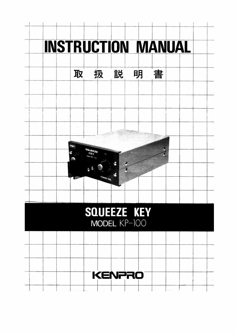
OPERATING MANUAL FOR KP-100 SQUEEZE KEY
FEATURES:
The KP-100 squeeze key is used CMOS ICs and silicon transistors in the circuit.Keying operation is available whichever transistor switch or relay switch.Built-in monitor speaker.Monitor sound can be changed variably.The KP-100 squeeze key can be operate at AC 117/220 V or DC 13.8 V.Dot and dash code are transmitted as complete code without keying speed control.
PRE OPERATION:
Check be made prior to actual AC operation that the selector switch which is located bottom side ofthe KP-100 is in conformity with your local AC line voltage.
Don't make use of keying voltage and current in exceeding DC 150 V, 1 A, in transistor keying ope-ration. If desire to operate at high voltage in exceeding DC 150 V, 1 A, relay keying operation isrecommended. Relay keying output voltage is 500 V maximum at open circuit and key-down cur-rent is 500 mA maximum.
Please be noticed that the keying transistor 2SC2233 is out of objection of guarantee, even the KP-100 is in validity of warrantee.
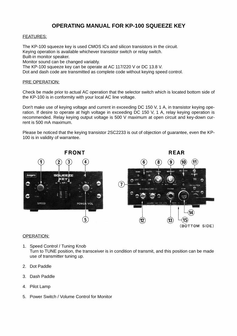
OPERATION:
1. Speed Control / Tuning KnobTurn to TUNE position, the transceiver is in condition of transmit, and this position can be madeuse of transmitter tuning up.
2. Dot Paddle
3. Dash Paddle
4. Pilot Lamp
5. Power Switch / Volume Control for Monitor
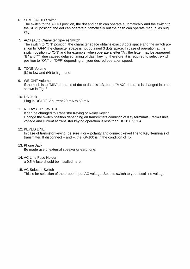
6. SEMI / AUTO SwitchThe switch to the AUTO position, the dot and dash can operate automatically and the switch tothe SEMI position, the dot can operate automatically but the dash can operate manual as bugkey.
7. ACS (Auto Character Space) SwitchThe switch to "ON" position, the character space obtains exact 3 dots space and the switch po-sition to "OFF" the character space is not obtained 3 dots space. In case of operation at theswitch position to "ON" and for example, when operate a letter "A", the letter may be appeared"E" and "T" due caused delayed timing of dash keying, therefore, it is required to select switchposition to "ON" or "OFF" depending on your desired operation speed.
8. TONE Volume(L) to low and (H) to high tone.
9. WEIGHT VolumeIf the knob is to "MIN", the ratio of dot to dash is 1:3, but to "MAX", the ratio is changed into asshown in Fig. 3.
10. DC JackPlug in DC13.8 V current 20 mA to 60 mA.
11. RELAY / TR. SWITCHIt can be changed to Transistor Keying or Relay Keying.Change the switch position depending on transmitters condition of Key terminals. Permissiblevoltage and current at transistor keying operation is less than DC 150 V, 1 A.
12. KEYED LINEIn case of transistor keying, be sure + or – polarity and connect keyed line to Key Terminals oftransmitter. If disconnect + and –, the KP-100 is in the condition of TX.
13. Phone JackBe made use of external speaker or earphone.
14. AC Line Fuse Holdera 0.5 A fuse should be installed here.
15. AC Selector SwitchThis is for selection of the proper input AC voltage. Set this switch to your local line voltage.
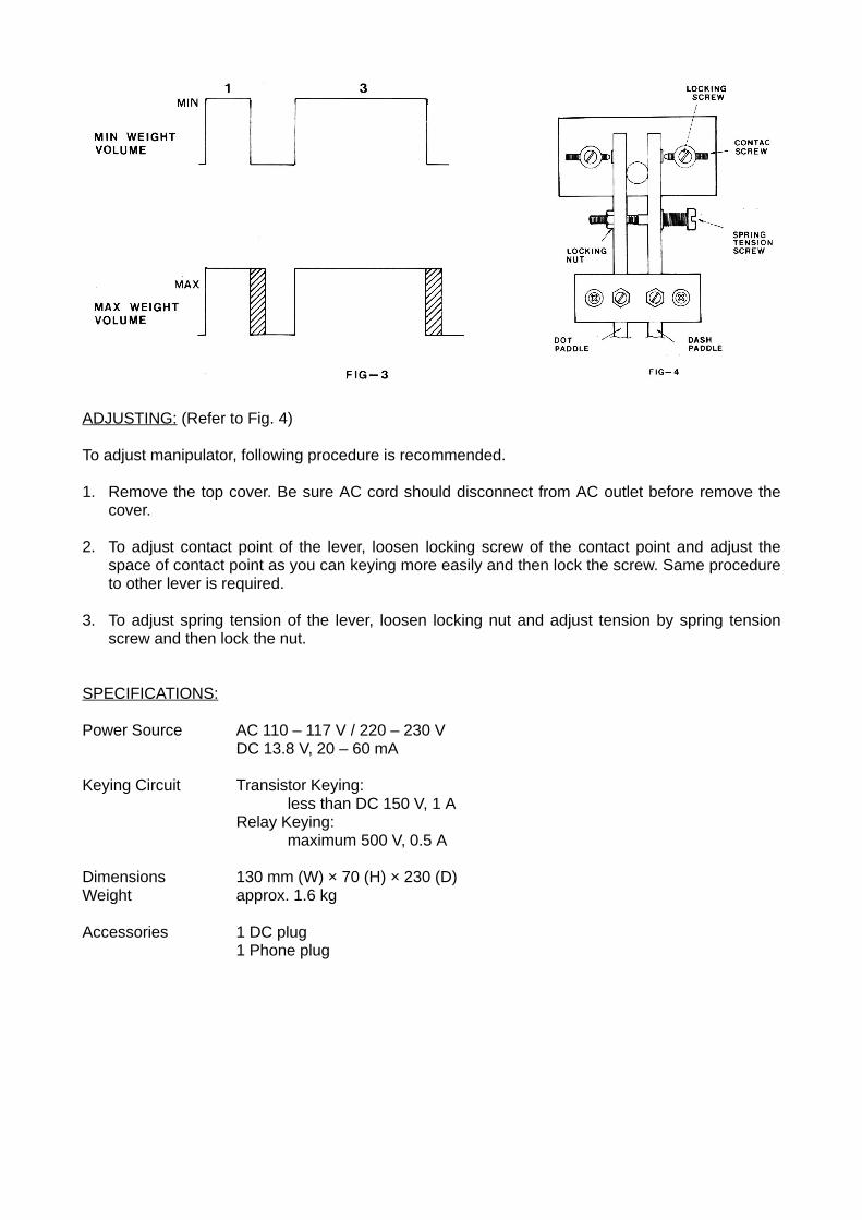
ADJUSTING: (Refer to Fig. 4)
To adjust manipulator, following procedure is recommended.
1. Remove the top cover. Be sure AC cord should disconnect from AC outlet before remove thecover.
2. To adjust contact point of the lever, loosen locking screw of the contact point and adjust thespace of contact point as you can keying more easily and then lock the screw. Same procedureto other lever is required.
3. To adjust spring tension of the lever, loosen locking nut and adjust tension by spring tensionscrew and then lock the nut.
SPECIFICATIONS:
Power Source AC 110 – 117 V / 220 – 230 VDC 13.8 V, 20 – 60 mA
Keying Circuit Transistor Keying:less than DC 150 V, 1 A
Relay Keying:maximum 500 V, 0.5 A
Dimensions 130 mm (W) × 70 (H) × 230 (D)Weight approx. 1.6 kg
Accessories 1 DC plug1 Phone plug