Ken Youssefi MAE dept. 1 Pressurized Cylinders Pipes carrying pressurized gas or liquid. Press or...
18
Ken Youssefi MAE dept. 1 Pressurized Cylinders Pipes carrying pressurized gas or liquid. Press or shrink fits Pressurize d cylinders Hydraulic or pneumatic actuators
-
Upload
lilian-harvey -
Category
Documents
-
view
225 -
download
0
Transcript of Ken Youssefi MAE dept. 1 Pressurized Cylinders Pipes carrying pressurized gas or liquid. Press or...

Ken Youssefi MAE dept. 1
Pressurized CylindersPipes carrying pressurized gas or liquid.
Press or shrink fits
Pressurized cylinders
Hydraulic or pneumatic actuators

Ken Youssefi MAE dept. 2
Stresses in Pressurized Cylinders Cylindrical pressure vessels, hydraulic cylinders, shafts with components mounted on (gears, pulleys, and bearings), gun barrels, pipes carrying fluids at high pressure,….. develop tangential, longitudinal, and radial stresses.
Wall thickness
t
A pressurized cylinder is considered a thin-walled vessel if the wall thickness is less than one-twentieth of the radius.
< 1/20tr
Thin-walled pressure vessel
Stress element
Small element
Tangential stress θ
Hoop stress
Longitudinal stressl
(closed ends)
Radial stress
r

Ken Youssefi MAE dept. 3
Stresses in a Thin-Walled Pressurized Cylinders
In a thin-walled pressurized cylinder the radial stress is much smaller than the tangential stress and can be neglected.
Longitudinal stress, l
(l) /4 [ (do)2 – (di)
2] = ( p ) /4 (di)2
Internal pressure, p
Fy = 0
Longitudinal stress
(l) [ (di + 2t)2 – (di)2] = ( p ) (di)
2
4t2 is very small,
(l) (4di t) = ( p ) (di)2
l = p di
4 tl =
p (di + t)4 t
Max. longitudinal stress
Pressure area
Ken Youssefi MAE dept. 4
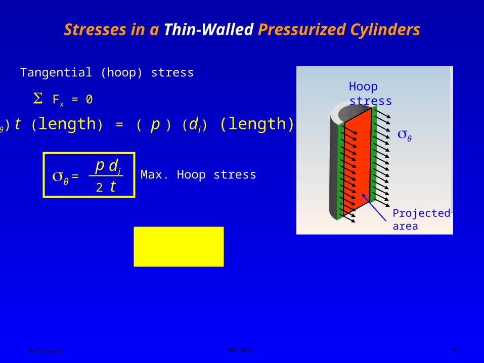
Stresses in a Thin-Walled Pressurized Cylinders
Projected area
Hoop stress
θ
Tangential (hoop) stress
2(θ) t (length) = ( p ) (di) (length)
Fx = 0
θ = p di 2 t
Max. Hoop stress
l = ½ θ

Ken Youssefi MAE dept. 5
Stresses in a Thick-Walled Pressurized Cylinders
In case of thick-walled pressurized cylinders, the radial stress, r , cannot be neglected.
Assumption – longitudinal elongation is constant around the plane of cross section, there is very little warping of
the cross section, εl = constant
dr
θ θ
r + dr
r
2(θ)(dr)(l) + r (2rl) – (r + dr) [2(r + dr)l] = 0
l = length of cylinder
F = 0
(dr) (dr) is very small compared to
other terms ≈ 0
θ – r – r drdr
= 0 (1)

Ken Youssefi MAE dept. 6
Stresses in a Thick-Walled Pressurized Cylinders
εl = – μθ
E
r
E– μ
Deformation in the longitudinal direction
θ + r = 2C1=εl E
μ
constant
(2)
Consider,
d (r r 2)
dr= r 2
dr
dr+ 2r r
Subtract equation (1) from (2),
r + r + r dr
dr= 2C1
θ – r – r dr
dr= 0 (1)
2rr + r2 dr
dr = 2rC1
Multiply the above equation by r
d (r r 2)
dr= 2rC1
r r 2 = r2C1 + C2
r = C1
C2
r2+ θ = C1
C2–
r2

Ken Youssefi MAE dept. 7
Stresses in a Thick-Walled Pressurized Cylinders
Boundary conditions
r = - pi at r = ri
r = - po at r = ro
θ =pi ri
2 - po ro2 – ri
2 ro2 (po – pi) / r
2
ro2 - ri
2Hoop stress
r =pi ri
2 - po ro2 + ri
2 ro2 (po – pi) / r
2
ro2 - ri
2
Radial stress
pi ri2 - po ro
2
l =ro
2 - ri2
Longitudinal stress
Longitudinal stress, l
Pressure area

Ken Youssefi MAE dept. 8
Stresses in a Thick-Walled Pressurized Cylinders
Special case, po (external pressure) = 0
θ =pi ri
2
ro2 - ri
2(1 +
ro2
r2) r =
ro2 - ri
2(1 -
ro2
r2)
pi ri2
Hoop stress distribution, maximum at the inner surface
Radial stress distribution, maximum at the inner surface

Ken Youssefi MAE dept. 9
Press and Shrink fitting Components onto Shafts
Liquid Nitrogen is fed into a containment unit that isolates the area to be fitted.
Shrink fitting a gear onto a shaft
The shrinking permits fitting of slightly oversized metal items into mating parts.

Ken Youssefi MAE dept. 10
Press and Shrink (Force) Fits
ds (shaft) > dh (hub)Inner member
Outer member
p (contact pressure) = pressure at the outer surface of the inner member or pressure at the inner surface of the outer member.
Consider the inner member at the interface
po = p
pi = 0
ri = ri
ro = R
iθ =pi ri
2 - po ro2 – ri
2 ro2 (po – pi) / r
2
ro2 - ri
2
iθ =– po R
2 – ri2 R2 p / R2
R2 – ri2
= – p R2 – ri
2
R2 + ri2
ir = – po = – p

Ken Youssefi MAE dept. 11
Press and Shrink Fits
Consider the outer member at the interfacepo = 0
pi = pri = R
ro = rooθ = p ro
2 – R2
R2 + ro2
or = – p
o = increase in the inner radius of the outer member
i = decrease in the outer radius of the inner member
Tangential strain at the inner radius of the outer member
εot = oθ
Eo
or
Eo
– μo
εot = o
R
o =Rp
Eo ro2 – R2
R2 + ro2
+ μo( )
Radial interference, = o – i

Ken Youssefi MAE dept. 12
Press and Shrink Fits
Tangential strain at the outer radius of the inner member
εit = iθ
Ei
ir
Ei
– μi
εit = i
R–
i =Rp
Ei R2 – ri2
R2 + ri2
+ μi( )–
Radial interference, = o – i
=Rp
Eo ro2 – R2
R2 + ro2
+ μo( ) Rp
Ei R2 – ri2
R2 + ri2
+ μi( )+
If both members are made of the same material then, E = Eo = Ei and μ = μo = μi
p = E R
(R2 – ri2)(ro
2 – R2)
(ro2 - ri
2)2R2

Ken Youssefi MAE dept. 13
Press and Shrink Fits - Example
You are asked to press fit a gear onto a shaft, specify the FN type fit. The shaft carries a maximum of 110 hp at 650 rpm and has a 2.0 inch diameter. The hub of the gear has a length of 2.0 inch and its outside diameter is 3.0 inch. Both components are made of steel with Sy = 40,000 psi
Hub
Shaft
Gear
2.02.0
3.0
hp =63000
T ω, 110 =
63000
T (650)
T = 10,662 in - lb Torque carried by the shaft
T = f R ( 2 R l ) p
Frictional torque
Surface areashaft radius
Coefficient of friction
Contact length between hub and shaft
Min. contact pressure

Ken Youssefi MAE dept. 14
Press and Shrink Fits - Example
T = f R ( 2 R l ) p ,
Frictional torque
10662 = .2 (1) ( 2 x 1 x 2 ) p
p = 4243 psi Minimum contact pressure required to carry the desired torque.
Calculate the radial interference needed
p = E R
(R2 – ri2)(ro
2 – R2)
(ro2 - ri
2)2R2
ri = 0
ro = 1.5
R = 1.0
4243 =30 x 106 ()
1
[(1.5)2 – (1)2] [(1)2 – (0)2]
2(1)2[( 1.5)2 – (0)2]
δ = .00050916 in. 2δ = .00102 = 1.02 x 10⁻³ in.Diametral interference needed

Ken Youssefi MAE dept. 15
ANSI Tables for FitsInterference fits (Force and Shrink fits) – FN1 to FN5
2.00

Ken Youssefi MAE dept. 16
Press and Shrink Fits - Example
0.6 x 10⁻³ minimum interferenceFN1
1.8 x 10⁻³ maximum interference
0.8 x 10⁻³ minimum interferenceFN2
2.7 x 10⁻³ maximum interference
1.3 x 10⁻³ minimum interferenceFN3
3.2 x 10⁻³ maximum interference
2δ = .00102 = 1.02 x 10⁻³ in.
Diametral interference needed
Select FN3 fit

Ken Youssefi MAE dept. 17
Press and Shrink Fits - ExampleCheck for failure of the shaft and the hub of the gear for max. interference fit
iθ =– po R
2 – ri2 R2 p / R2
R2 – ri2
= – p R2 – ri
2
R2 + ri2
ir = – po = – p
Shaft (outer surface of inner member), ri = 0
= – p
Maximum contact pressure for maximum interference,
(2δ)max = 3.2 x 10⁻³ in.
p =30 x 106 (1.6x 10⁻³)
1
[(1.5)2 – (1)2] [(1)2 – (0)2]
2(1)2[( 1.5)2 – (0)2]= 13,333 psi
iθ = 13333 < 40000 = Sy shaft will not fail

Ken Youssefi MAE dept. 18
Press and Shrink Fits - Example
Hub (inner surface of outer member), ri = R
= 13333 1.52 – 12
1.52 + 12
oθ =– po R
2 – ro2 R2 p / R2
R2 – ro2
= p R2 – ro
2
R2 + ro2
or = – po = – p = -13333
= 34666 psi
oθ = 34666 < 40000 = Sy Hub will not fail