Keep Geometry in Context: Using Contextual Priors...
8
Keep Geometry in Context: Using Contextual Priors for Very-Large-Scale 3D Dense Reconstructions Michael Tanner † Pedro Pini´ es † Lina Mar´ ıa Paz † Paul Newman † Fig. 1. This paper is about the efficient generation of dense models of very-large-scale environments from range data. Abstract—This paper is about the efficient generation of dense models of very large-scale environments from depth data and in particular, stereo-camera-based depth data. Better maps make for better understanding; better understanding leads to better robots, but this comes at a cost: the computational and memory requirements of large dense models can be prohibitive. We provide the theory and the system needed to create very- large-scale dense reconstructions. To this end, we leverage three sources of geometric and contextual information. First, we apply a 2D Total Generalized Variation (TGV) regularizer to our depth maps as this conforms to the affine-smooth surfaces visible in the images. Second, we augment the TGV regulariser with an appearance prior, specifically an anisotropic diffusion tensor. Finally, we use the computationally efficient 3D Total Variation (TV) regularizer on our 3D reconstructions to enforce piecewise- constant surfaces over a sequence of fused depth maps. Our TV regularizer operates over a compressed 3D data structure while handling the complex boundary conditions compression introduces. Only when we regularize in both 2D (stereo depth maps) and 3D (dense reconstruction) can we swiftly create “well behaved” reconstructions. We evaluate our system on the KITTI dataset and provide reconstruction error statistics when compared to 3D laser. Our 3D regularizer reduces median error by 40% (vs. a 2D-only regularizer) in 3.4 km of dense reconstructions. Our final median reconstruction accuracy is 6 cm. For subjective analysis, we provide a review of 6.1 km of dense reconstructions in the below video. These are the largest regularized dense reconstructions from a passive stereo camera we are aware of in the literature. Video: https://youtu.be/FRmF7mH86EQ I. I NTRODUCTION AND PREVIOUS WORK Over the past few years, the development of 3D reconstruc- tion systems has undergone an explosion facilitated by ad- vances in GPUs. Earlier, large-scale efforts such as [18][1][6] † Mobile Robotics Group Department of Engineering Science University of Oxford 17 Parks Road, Oxford OX1 3PJ, United Kingdom mtanner,ppinies,linapaz,[email protected] reconstructed sections of urban scenes from unstructured photo collections. The ever-strengthening theoretical foundations of continuous optimization [3][8], upon which the most advanced algorithms rely, have become accessible for robotics and com- puter vision applications. Together these strands – hardware and theory – allow us to build systems which create very- large-scale 3D dense reconstructions. However, the state of the art of many 3D reconstruction systems rarely considers scalability for practical applications (e.g., autonomous driving and inspection). The most general approaches are motivated by recent mobile phone and tablet development [13][5] with an eye on small-scale reconstruction. We review the taxonomy of 3D reconstruction systems by considering the nature of the workspace to be modelled and the data-collection platform used. We highlight the difference between dense reconstruction with a mobile robot [26] versus object-centered modelling [15][22]. The former suggests the workspace is discovered while traversed — e.g., driving a car [28][26][5]. In contrast, in object-centred applications the goal is to generate models from sensor data gathered by pre-selected viewpoints [4][15][19]. The main difference is in the way the scene is observed; object reconstruction requires an active interaction with the scene [19][22]. In this paper we focus solely on passive reconstruction using contextual priors. Since we do not directly control the camera motion and therefore do not observe surfaces from multiple angles, these contextual priors improve the final reconstruction through reasonable assumptions about the data’s underlying structure. Our use stands in contrast to the object-centric contextual priors dominant in the literature which are either tightly coupled with scene segmentation [9][32][10] or are computationally prohibitive [25]. Rather, our global contextual prior is “urban environment,” so we reach for the TV and TGV local-prior (piecewise constant and affine smooth) regularizers to efficiently produce high-quality reconstructions.
Transcript of Keep Geometry in Context: Using Contextual Priors...

Keep Geometry in Context: Using Contextual Priors for
Very-Large-Scale 3D Dense Reconstructions
Michael Tanner† Pedro Pinies† Lina Marıa Paz† Paul Newman†
Fig. 1. This paper is about the efficient generation of dense models of very-large-scale environments from range data.
Abstract—This paper is about the efficient generation of densemodels of very large-scale environments from depth data and inparticular, stereo-camera-based depth data. Better maps makefor better understanding; better understanding leads to betterrobots, but this comes at a cost: the computational and memoryrequirements of large dense models can be prohibitive.
We provide the theory and the system needed to create very-large-scale dense reconstructions. To this end, we leverage threesources of geometric and contextual information. First, we applya 2D Total Generalized Variation (TGV) regularizer to our depthmaps as this conforms to the affine-smooth surfaces visible inthe images. Second, we augment the TGV regulariser with anappearance prior, specifically an anisotropic diffusion tensor.Finally, we use the computationally efficient 3D Total Variation(TV) regularizer on our 3D reconstructions to enforce piecewise-constant surfaces over a sequence of fused depth maps. OurTV regularizer operates over a compressed 3D data structurewhile handling the complex boundary conditions compressionintroduces. Only when we regularize in both 2D (stereo depthmaps) and 3D (dense reconstruction) can we swiftly create “wellbehaved” reconstructions.
We evaluate our system on the KITTI dataset and providereconstruction error statistics when compared to 3D laser. Our3D regularizer reduces median error by 40% (vs. a 2D-onlyregularizer) in 3.4 km of dense reconstructions. Our final medianreconstruction accuracy is 6 cm. For subjective analysis, weprovide a review of 6.1 km of dense reconstructions in the belowvideo. These are the largest regularized dense reconstructionsfrom a passive stereo camera we are aware of in the literature.
Video: https://youtu.be/FRmF7mH86EQ
I. INTRODUCTION AND PREVIOUS WORK
Over the past few years, the development of 3D reconstruc-
tion systems has undergone an explosion facilitated by ad-
vances in GPUs. Earlier, large-scale efforts such as [18][1][6]
†Mobile Robotics GroupDepartment of Engineering ScienceUniversity of Oxford17 Parks Road, OxfordOX1 3PJ, United Kingdommtanner,ppinies,linapaz,[email protected]
reconstructed sections of urban scenes from unstructured photo
collections. The ever-strengthening theoretical foundations of
continuous optimization [3][8], upon which the most advanced
algorithms rely, have become accessible for robotics and com-
puter vision applications. Together these strands – hardware
and theory – allow us to build systems which create very-
large-scale 3D dense reconstructions.
However, the state of the art of many 3D reconstruction
systems rarely considers scalability for practical applications
(e.g., autonomous driving and inspection). The most general
approaches are motivated by recent mobile phone and tablet
development [13][5] with an eye on small-scale reconstruction.
We review the taxonomy of 3D reconstruction systems by
considering the nature of the workspace to be modelled and
the data-collection platform used. We highlight the difference
between dense reconstruction with a mobile robot [26] versus
object-centered modelling [15][22]. The former suggests the
workspace is discovered while traversed — e.g., driving a
car [28][26][5]. In contrast, in object-centred applications
the goal is to generate models from sensor data gathered
by pre-selected viewpoints [4][15][19]. The main difference
is in the way the scene is observed; object reconstruction
requires an active interaction with the scene [19][22]. In
this paper we focus solely on passive reconstruction using
contextual priors. Since we do not directly control the camera
motion and therefore do not observe surfaces from multiple
angles, these contextual priors improve the final reconstruction
through reasonable assumptions about the data’s underlying
structure. Our use stands in contrast to the object-centric
contextual priors dominant in the literature which are either
tightly coupled with scene segmentation [9][32][10] or are
computationally prohibitive [25]. Rather, our global contextual
prior is “urban environment,” so we reach for the TV and TGV
local-prior (piecewise constant and affine smooth) regularizers
to efficiently produce high-quality reconstructions.

Dense Fusion
Velodyne HDL-32E Sick LMS-151
Surface Extraction
Regularization
3D Model
Localization
Stereo Images
Depth Map Estimation
Mono Images Stereo Images
Velodyne HDL-32E Sick LMS-151
Fig. 2. An overview of our software pipeline. Our Dense Fusion moduleaccepts range data from either laser sensors or depth maps created from monoor stereo cameras. We regularise the model in 3D space, extract the surface,and then provide the final 3D model to other components on our autonomousrobotics platform (e.g., segmentation, localisation, planning, or visualisation).Blue modules are discussed in further detail in Sections III-IV.
An important characteristic of 3D mapping algorithms is
their choice of representation. Some traditional Structure from
Motion (SfM) and Simultaneous Localization and Mapping
(SLAM) algorithms still believe in sparse or semi-dense rep-
resentations [2][14][5] or trust probabilistic occupancy grids
[29] or mesh models [18]. Although these approaches may be
sufficient for localisation, their maps lack the richness prereq-
uisite for a variety of applications, including robot navigation,
active perception, and semantic scene understanding. In con-
trast, dense 3D reconstruction systems use an implicit surface
representation built from consecutive sensor observations [4].
To this end, we find data structures such as voxel grids [31],
point based structures [11], or more recently compressed voxel
grids [24][26][22].
The accuracy of the reconstruction also varies with the
sensor type, ranging from monocular cameras, stereo cameras,
RGB-D cameras [12][16][15][28][31][13][26][22], to 3D laser
[29]. Although RGB-D cameras generate very accurate mod-
els, their depth observations are limited to a few meters. This
restricts their use to small-scale and (usually) indoor work-
spaces [13][15][11][28][31][22].
Our contributions are as follows. First, we present a method
to regularize 3D data — in contrast to the 2D-only regularizers
which dominate the literature — stored in a compressed
volumetric data structure, specifically the Hashing Voxel Grid
[17]. This enables optimal 3D regularization of scenes an
order of magnitude larger than previously possible. The key
difficulty (and hence our vital contribution) with compressed
3D structures is the presence of many additional boundary
conditions. Accurately computing the gradient and divergence
operators, both of which are required to minimize the system’s
energy, becomes a non-trivial problem.
Second, we present a system which efficiently combines
state-of-the-art components for depth map estimation, fusion,
and regularization.
Finally, our quantitative results in Table I serve as a new
public-data benchmark for the community to compare dense-
map reconstructions. We hope this becomes a tool for the
dense mapping community.
II. SYSTEM OVERVIEW
At its core, our system (Figure 2) consumes range data
and produces a 3D model. For the passive reconstructions
considered in this paper, our input is created from stereo
images, however our system can handle a variety of sensors
(e.g., active cameras and 2D/3D scanning lasers).
The pipeline consists of a Localization module responsible
for providing sensor pose estimates. The Depth Map Esti-
mation module processes stereo frames into a stream of 2D
regularized depth maps. The Dense Fusion module merges
the range data into a compressed 3D data structure that is
then regularized. A surface model can be extracted for parallel
processing in a separate application (e.g., planner).
III. DEPTH-MAP ESTIMATION
This section describes our module that produces a stream
of depth maps (D) which are the input to the Section IV’s
3D fuser. We pose this as an energy minimization with a
regularization term and a data term:
E(·) = Eregularization(·)+Edata(·) (1)
The data term measures the similarity between correspond-
ing pixels in the stereo images [20]. We emphasize this section
describes the 2D regularization case, whereas Section IV
presents the sparse-in-literature 3D regularization case.
A. Census Transform Signature Data Term
The data term is given by:
Edata(d; IL, IR) =
¨
Ω
|ρ(d,x,y)|dxdy (2)
where the coordinates are (x,y) for a particular pixel in the
reference image, and the function ρ(d,x,y) = SimW (IL(x +d,y), IR(x,y)) measures the similarity between two pixels using
a window of size W for a candidate disparity d ∈ D. We use
the Census Transform Signature (CTS) [30] as our similarity
metric as it is both illumination invariant and fast to compute.
B. Affine Regularization
For ill-posed problems like depth-map estimation, good and
apt priors are essential. A common choice is TV regularization
which favors piecewise-constant solutions. However, its use
lends to poor depth-map estimates over outdoor sequences
by creating fronto-parallel surfaces. Figure 3 shows artifacts
created by planar surfaces not orthogonal to the image plane
(e.g. the roads and walls which dominate our urban scenes).
Thus we reach for a Total Generalized Variation (TGV)
regularization term which favours planar surfaces in any
orientation:
Ereg(d) = minw∈R2
α1
¨
Ω
|T ∇d −w|dx dy+α2
¨
Ω
|∇w|dx dy
(3)
where w allows the disparity d in a region of the depth
map to change at a constant rate and therefore creates planar
surfaces with different orientations and T preserves object
discontinuities.

Fig. 3. Comparison of three depth-map regularizers: TV, TGV, and TGV-Tensor. Using the reference image (top), the TV regularizer (left) favours fronto-parallel surfaces, therefore it creates a sharp discontinuity for the shadow on the road (red rectangle) and attaches the rubbish bin to the rear of the car (redcircle). TGV (center) improves upon this by allowing planes at any orientation, but it still cannot identify boundaries between objects: the rubbish bin is againestimated as part of the car. Finally, the TGV-Tensor (right) regularizer both allows planes at any orientation and is more successful at differentiating objectsby taking into account the normal of the color image’s gradient. For clarity, the reconstructions have a different viewing origin than the reference image.
C. Leveraging Appearance
A common problem that arises during the energy minimiza-
tion is the tension between preserving object discontinuities
while respecting the smoothness prior. Ideally the solutions
preserve intra-object continuity and inter-object discontinuity.
One may mitigate this tension by using the isotropic ap-
pearance gradient (∇I) as an indicator of boundaries between
objects. However, though this aids the regularizer, it does not
contain information about the direction of the border between
the objects. To take this information into account we adopt an
anisotropic (as opposed to isotropic) diffusion tensor:
T = exp(−γ|∇I|β )nnT +n⊥n⊥T
(4)
where n = ∇I|∇I| and n⊥ is its orthogonal complement. When
used in Equation 3, T decomposes the disparity’s gradient (∇d)
in directions aligned with n and n⊥. We penalize components
aligned with n⊥, but do not penalize large gradient components
aligned with n. In other words, if there is a discontinuity
visible in the color image, then it is highly probable that there
is a discontinuity in the depth image. The benefits of this tensor
term are visually depicted in Figure 3.
IV. 3D DENSE MAPS
The core of the 3D dense mapping system consists of a
Dense Fusion module which integrates a sequence of depth
observations into a volumetric representation, and the Regular-
isation module smooths noisy surfaces and removes uncertain
surfaces.
A. Fusing Data
To create a dense reconstruction, one must process the
depth values within a data structure which can efficiently
represent surfaces and continually improve that representation
with future observations. Simply storing each of the range
estimates (e.g., as a point cloud) is a poor choice as storage
grows without bound and the surface reconstruction does not
improve when revisiting a location.
A common approach is to select a subset of space in
which one will reconstruct surfaces and divide the space into
a uniform voxel grid. Each voxel stores range observations
represented by their corresponding Truncated Signed Distance
Function (TSDF), uT SDF . The voxels’ TSDF values are com-
puted such that one can solve for the zero-crossing level set
(isosurface) to find a continuous surface model. Even though
the voxel grid is a discrete field, because the TSDF value is a
real number, the surface reconstruction is even more precise
than the voxel size.
Due to memory constraints, only a small subset of space
can be reconstructed using a legacy approach where the
grid is fixed in space and therefore reconstructs only a few
cubic meters. This presents a problem in mobile robotics
applications since the robot’s exploration region is restricted
to a prohibitively small region. In addition, long-range depth
sensors (e.g., laser) cannot be fully utilised since their range
exceeds the size of the voxel grid (or local voxel grid if a
local-mapping approach is used) [27].
A variety of techniques were proposed in recent years to
remove these limits. They leverage the fact the overwhelming
majority of voxels do not contain any valid TSDF data since
they were never directly observed by the sensor. A compressed
data structure only allocates and stores data in voxels which
are near a surface.
The most successful approach is the Hashing Voxel Grid
(HVG) [17]. The HVG subdivides the world into an infinite,
uniform grid of voxel blocks, each of which represents its
own small voxel grid with 8 voxels in each dimension (512
total). Anytime a surface is observed within a given voxel
block, all the voxels in that block are allocated and their TSDF
values are updated. Blocks are only allocated where surfaces
are observed.
Applying a hash function to coordinates in world space
gives an index within the hash table, which in turn points
to the raw voxel data. Figure 4 provides a graphical overview
of this process, and we refer the reader to the original HVG
paper [17] for further implementation details.
If one considers each HVG voxel block to be a legacy voxel
grid, then the update equations are identical to those presented
by [15]. This method projects voxels into the depth map to

Range Sensor
Surfaces
Unused
Voxel
Blocks
Allocated
Voxel Blocks
Hash Table
Voxel Blocks
Bucket
Ω
Ω"
Fig. 4. A depiction of our novel combination of the Hashing Voxel Grid(HVG) data structure with regularization to fuse depth observations from theenvironment. The HVG enables us to reconstruct large-scale scenes by onlyallocating memory for the regions of space in which surfaces are observed(i.e., the colored blocks). To avoid generating spurious surfaces, we mark eachvoxel with an indicator variable (Ω) to ensure the regularizer only operates onvoxels in which depth information was directly observed. This same approachis used independent of the range sensor — e.g., stereo depth maps or laser.Figure inspired by [17].
update f , but this can be extended to work with laser sensors
by only updating voxels along the ray from the laser sensor
to −µ (a user-defined system parameter) behind the surface.
B. 3D Regularization
We pose the fusion step as a noise-reduction problem that
can be approached by a continuous energy minimization over
the voxel-grid domain (Ω):
E(u) =
ˆ
Ω
|∇u|dΩ+λ
ˆ
Ω
|| f −u||22dΩ (5)
where E(u) is the energy (which we seek to minimize) of
the denoised (u) and noisy ( f ) TSDF data. The regularization
energy term, commonly referred to as a Total Variation (TV)
regularizer, seeks to fit the solution (u) to a specified prior
— the L1 norm in this case. The data energy term seeks to
minimize the difference between the u and f , while λ controls
the relative importance of the data term vs. the regularizer
term.
In practice, the TV norm has a two-fold effect: (1) smooths
out the reconstructed surfaces, and (2) removes surfaces which
are “uncertain” — i.e., voxels with high gradients and few
direct observations. However, since compressed data structures
are not regular in 3D space, the proper method to compute
the gradient (and its dual: divergence) in the presence of
the additional boundary conditions is not straightforward —
hence why we believe this has remained an open problem.
In addition, improper gradient and divergence operators will
cause the regulariser to spuriously extrapolate surfaces into
undesired regions of the reconstruction [23].
We leverage the legacy voxel grid technique [23] into
the HVG by introducing a new state variable in each voxel
indicating whether or not it was directly observed by a range
sensor. The subset of voxels which were observed are defined
as Ω, the set solely upon which the regluarizer is constrained
to operate. Note that all voxel blocks which are not allocated
are in Ω. A graphical depiction of the Ω and Ω for a sample
surface is provided in Figure 4.
The additional boundary conditions introduced by the HVG
require careful derivation of the gradient (Equation 6) and
divergence (Equation 7) operators to take into account whether
or not neighbors are in Ω. We define the gradient as:
∇xui, j,k =
ui+1, j,k −ui, j,k if 1 ≤ i <Vx
0 if i =Vx
0 if ui, j,k ∈ Ω
0 if ui+1, j,k ∈ Ω
(6)
where ui, j,k is a voxel’s TSDF value at the 3D world integer
coordinates (i, j,k), and Vx is the number of voxels in the x
dimension. The gradient term in the regularizer encourages
smoothness across observed (Ω) neighboring voxels while
excluding unobserved (Ω) voxels.
To solve the primal’s dual optimization problem (Sec-
tion IV-C), we must define the divergence operator as the dual
of the new gradient operator:
∇x ·pi, j,k =
pxi, j,k −px
i−1, j,k if 1 < i <Vx
pxi, j,k if i = 1
−pxi−1, j,k if i =Vx
0 if ui, j,k ∈ Ω
pxi, j,k if ui−1, j,k ∈ Ω
−pxi−1, j,k if ui+1, j,k ∈ Ω
(7)
Each voxel block is treated as a voxel grid with boundary
conditions determined by its neighbors’ Ω indicator function,
IΩ. The regularizer operates only on the voxels within Ω, the
domain of integration, and thus it neither spreads spurious
surfaces into unobserved regions nor updates valid voxels with
invalid TSDF data. Note that both equations are presented for
the x-dimension, but the y and z-dimension equations can be
obtained by variable substitution between i, j, and k.
C. Implementation of 3D Energy Minimization
In this section, we describe the algorithm to solve Equa-
tion 5 and point the reader to [3][21] for a detailed derivation
of these steps. We vary from their methods only in our new
definition for the gradient and divergence operators.
Equation 5 is not smooth so it cannot be minimized with tra-
ditional techniques. We use the Legendre-Fenchel Transform
[21] and the Proximal Gradient method [3] to transform our
TV cost-function into a form efficiently solved by a Primal-
Dual optimization algorithm [3]:
1) p, u, and u are initialised to 0. u is a temporary variable
which reduces the number of optimization iterations
required to converge.
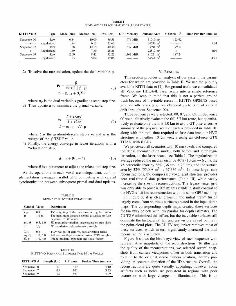
TABLE ISUMMARY OF ERROR STATISTICS (10 CM VOXELS)
KITTI-VO # Type Mode (cm) Median (cm) 75% (cm) GPU Memory Surface Area # Voxels 106 Time Per Iter. (mm:ss)
Sequence 00 Raw 0.84 10.00 36.51 976 MiB 51010 m2 123.62
Regularized 1.84 6.15 23.60 34630 m2 5:24
Sequence 07 Raw 1.68 12.19 40.38 637 MiB 33891 m2 79.11
Regularized 1.69 7.30 26.21 22817 m2 4:10
Sequence 09 Raw 2.00 8.43 32.22 1,462 MiB 81624 m2 187.24
Regularized 1.83 5.04 19.06 54561 m2 4:41
2) To solve the maximisation, update the dual variable p,
pk =p
max(1, ||p||2)
p = pk−1 +σp∇u
(8)
where σp is the dual variable’s gradient-ascent step size.
3) Then update u to minimize the primal variable,
uk =u+ τλw f
1+ τλw
u = uk−1 − τ∇ ·p(9)
where τ is the gradient-descent step size and w is the
weight of the f TSDF value.
4) Finally, the energy converge in fewer iterations with a
“relaxation” step,
u = u+θ(u− u) (10)
where θ is a parameter to adjust the relaxation step size.
As the operations in each voxel are independent, our im-
plementation leverages parallel GPU computing with careful
synchronization between subsequent primal and dual updates.
TABLE IISUMMARY OF SYSTEM PARAMETERS
Symbol Value Description
λ3D 0.8 TV weighting of the data term vs. regularizationµ 1.0 m The maximum distance behind a surface to fuse
negative TSDF valuesσp, θ 0.5, 1.0 3D regularizer gradient-ascent/descent step sizes
τ 1/6 3D regularizer relaxation-step weight
λ2D 0.5 TGV weight of data vs. regularization termsα1,α2 1.0, 5.0 Affine-smooth/piecewise-constant TGV weightsβ , γ 1.0, 4.0 Image gradient exponent and scale factor
TABLE IIIKITTI-VO SCENARIOS SUMMARY FOR 10 CM VOXELS
KITTI-VO # Length (km) # Frames Fusion Time (mm:ss)
Sequence 00 1.0 1419 4:10Sequence 07 0.7 1101 3:23Sequence 09 1.7 1591 4:09
V. RESULTS
This section provides an analysis of our system, the param-
eters for which are provided in Table II. We use the publicly
available KITTI dataset [7]. For ground truth, we consolidated
all Velodyne HDL-64E laser scans into a single reference
frame. We keep in mind that this is not a perfect ground
truth because of inevitable errors in KITTI’s GPS/INS-based
ground-truth poses (e.g., we observed up to 3 m of vertical
drift throughout Sequence 09).
Three sequences were selected: 00, 07, and 09. In Sequence
00 we qualitatively evaluate the full 3.7 km route, but quantita-
tively evaluate only the first 1.0 km to avoid GT pose errors. A
summary of the physical scale of each is provided in Table III,
along with the total time required to fuse data into our HVG
structure with either 10 cm voxels using an GeForce GTX
TITAN with 6 GiB.
We processed all scenarios with 10 cm voxels and compared
the dense reconstruction model, both before and after regu-
larization, to the laser scans, see Table I. The regularizer on
average reduced the median error by 40% (10 cm → 6 cm), the
75-percentile error by 36% (36 cm → 23 cm), and the surface
area by 32% (55,008 m2 → 37,336 m2). In these large-scale
reconstructions, the compressed voxel grid structure provides
near real-time fusion performance (Table III) while vastly
increasing the size of reconstructions. The legacy voxel grid
was only able to process 205 m; this stands in stark contrast to
the HVG’s 1.6 km reconstruction with the same GPU memory.
In Figure 5, it is clear errors in the initial “raw” fusion
largely come from spurious surfaces created in the input depth
maps. The corresponding depth maps created these surfaces
for far-away objects with low paralax for depth estimates. The
2D TGV minimized this effect, but the inevitable surfaces still
dominate the histograms’ tail and are visible as red points in
the point-cloud plots. The 3D TV regularizer removes most of
these surfaces, which in turn significantly increased the final
reconstruction’s accuracy.
Figure 6 shows the bird’s-eye view of each sequence with
representative snapshots of the reconstructions. To illustrate
the quality of the reconstructions, we selected several snap-
shots from camera viewpoints offset in both translation and
rotation to the original stereo camera position, thereby pro-
viding an accurate depiction of the 3D structure. Overall, the
reconstructions are quite visually appealing; however, some
artifacts such as holes are persistent in regions with poor
texture or with large changes in illumination. This is an

Sequence 00
Sequence 07
Sequence 09
median = 10.00 cm
75% = 36.51 cm
median = 8.43 cm
75% = 32.22 cm
median = 5.04 cm
75% = 19.06 cm
median = 7.30 cm
75% = 26.21 cm
median = 6.15 cm
75% = 23.60 cm
Without Regularization With Regularization
median = 12.19 cm
75% = 40.38 cm
Fig. 5. A summary of the dense reconstruction quality for three scenarios (one scenario per row) from the KITTI-VO public benchmark dataset. The leftside are the results before regularization and the right side are after regularization. Next to each histogram of point-to-point errors is a top-view, coloredreconstruction errors corresponding to the same colors in the histogram. The regularizer reduces the reconstruction’s error approximately 40%, primarily byremoving uncertain surfaces — as can be seen when you contrast the raw (far left) and regularized (far right) reconstruction errors.
Sequence 00
Sequence 07
Sequence 09
Fig. 6. A few representative sample images for various points of views (offset from the original camera’s position) along each trajectory. All sample imagesare of the final regularized reconstruction with 10 cm voxels. The video provides full fly-through footage for each sequence.
expected result since, in these cases, no depth map can be
accurately inferred.
The video provides a fly-through of each sequence to visu-
alize the quality of our final regularized 3D reconstructions.
VI. CONCLUSION
By leveraging the geometric and contextual prior in urban
environments, we presented a state-of-the-art dense mapping
system for very-large-scale dense reconstructions. We utilized
the affine-smooth and piecewise consistency in our 2D and
3D models while also introducing an anisotropic diffusion
tensor to improve the quality of our input depth maps. We
overcame the primary technical challenge of compressed 3D
regularization by redefining the gradient and divergence oper-
ators to account for the additional boundary conditions. Our
3D regularizer consistently reduced the reconstruction error
metrics by 40% (vs. a 2D-only regularizer), for a median
accuracy of 6 cm over 2.8e5 m2 of constructed area. In future
work, we plan to use segmentation to select an appropriate
contextual prior to regularize each object (e.g., affine-smooth
for road/buildings, “vegetation” regularizer for trees, etc.).

REFERENCES
[1] Sameer Agarwal, Noah Snavely, Ian Simon, Steven M.
Seitz, and Richard Szeliski. Building rome in a day.
In Twelfth IEEE International Conference on Computer
Vision (ICCV 2009), Kyoto, Japan, September 2009.
IEEE.
[2] Pablo F. Alcantarilla, Chris Beall, and Frank Dellaert.
Large-scale dense 3d reconstruction from stereo imagery.
In In 5th Workshop on Planning, Perception and Navi-
gation for Intelligent Vehicles (PPNIV), Tokyo, Japan,
11/2013 2013.
[3] Antonin Chambolle and Thomas Pock. A First-Order
Primal-Dual Algorithm for Convex Problems with Ap-
plications to Imaging. J. Math. Imaging Vis., 40(1):120–
145, May 2011.
[4] Brian Curless and Marc Levoy. A volumetric method for
building complex models from range images. In Proceed-
ings of the 23rd annual conference on Computer graphics
and interactive techniques, pages 303–312. ACM, 1996.
02090.
[5] J. Engel, J. Stueckler, and D. Cremers. Large-scale direct
slam with stereo cameras. In International Conference
on Intelligent Robots and Systems (IROS), 2015.
[6] Yasutaka Furukawa, Brian Curless, Steven M. Seitz,
and Richard Szeliski. Towards internet-scale multi-
view stereo. In The Twenty-Third IEEE Conference on
Computer Vision and Pattern Recognition, CVPR 2010,
San Francisco, CA, USA, 13-18 June 2010, pages 1434–
1441, 2010.
[7] Andreas Geiger, Philip Lenz, and Raquel Urtasun. Are
we ready for Autonomous Driving? The KITTI Vision
Benchmark Suite. In Conference on Computer Vision
and Pattern Recognition (CVPR), 2012. 00627.
[8] Bastian Goldluecke, Evgeny Strekalovskiy, and Daniel
Cremers. The natural vectorial total variation which
arises from geometric measure theory. SIAM Journal
on Imaging Sciences, 5(2):537–563, 2012.
[9] Christian Haene, Christopher Zach, Andrea Cohen,
Roland Angst, and Marc Pollefeys. Joint 3D Scene
Reconstruction and Class Segmentation. In CVPR, 2013.
[10] Christian Haene, Nikolay Savinov, and Marc Pollefeys.
Class Specific 3D Object Shape Priors Using Surface
Normals. In CVPR, 2014.
[11] Maik Keller, Damien Lefloch, Martin Lambers, Shahram
Izadi, Tim Weyrich, and Andreas Kolb. Real-time 3d re-
construction in dynamic scenes using point-based fusion.
In 3DTV-Conference, 2013 International Conference on,
pages 1–8. IEEE, 2013.
[12] Young Min Kim, Christian Theobalt, James Diebel,
Jana Kosecka, Branislav Miscusik, and Sebastian Thrun.
Multi-view image and tof sensor fusion for dense 3d
reconstruction. In Computer Vision Workshops (ICCV
Workshops), 2009 IEEE 12th International Conference
on, pages 1542–1549. IEEE, 2009.
[13] Matthew Klingensmith, Ivan Dryanovski, Siddhartha
Srinivasa, and Jizhong Xiao. Chisel: Real time large scale
3d reconstruction onboard a mobile device. In Robotics
Science and Systems 2015, July 2015.
[14] Raul Mur-Artal, JMM Montiel, and Juan D Tardos. Orb-
slam: a versatile and accurate monocular slam system.
arXiv preprint arXiv:1502.00956, 2015.
[15] Richard A. Newcombe, Andrew J. Davison, Shahram
Izadi, Pushmeet Kohli, Otmar Hilliges, Jamie Shotton,
David Molyneaux, Steve Hodges, David Kim, and An-
drew Fitzgibbon. KinectFusion: Real-time dense surface
mapping and tracking. In Mixed and augmented reality
(ISMAR), 2011 10th IEEE international symposium on,
pages 127–136. IEEE, 2011.
[16] Richard A. Newcombe, Steven J. Lovegrove, and An-
drew J. Davison. DTAM: Dense tracking and mapping
in real-time. In Computer Vision (ICCV), 2011 IEEE
International Conference on, pages 2320–2327. IEEE,
2011. 00384.
[17] Matthias Nießner, Michael Zollhofer, Shahram Izadi, and
Marc Stamminger. Real-time 3D Reconstruction at Scale
Using Voxel Hashing. ACM Trans. Graph., 32(6):169:1–
169:11, November 2013. 00050.
[18] M. Pollefeys, D. Nister, J.-M. Frahm, A. Akbarzadeh,
P. Mordohai, B. Clipp, C. Engels, D. Gallup, S.-
J. Kim, P. Merrell, C. Salmi, S. Sinha, B. Talton,
L. Wang, Q. Yang, H. Stewenius, R. Yang, G. Welch, and
H. Towles. Detailed real-time urban 3d reconstruction
from video. International Journal of Computer Vision,
78(2-3):143–167, July 2008.
[19] V. Pradeep, C. Rhemann, S. Izadi, C. Zach, M. Bleyer,
and S. Bathiche. MonoFusion: Real-time 3D reconstruc-
tion of small scenes with a single web camera. In 2013
IEEE International Symposium on Mixed and Augmented
Reality (ISMAR), pages 83–88, October 2013.
[20] Rene Ranftl, Stefan Gehrig, Thomas Pock, and Horst
Bischof. Pushing the limits of stereo using variational
stereo estimation. In Intelligent Vehicles Symposium (IV),
2012 IEEE, pages 401–407. IEEE, 2012.
[21] R. T. Rockafellar. Convex Analysis. Princeton University
Press, Princeton, New Jersey, 1970.
[22] T. Schops, T. Sattler, C. Hane, and M. Pollefeys. 3D
modeling on the go: Interactive 3D reconstruction of
large-scale scenes on mobile devices. In International
Conference on 3D Vision (3DV), 2015.
[23] Michael Tanner, Pedro Pinies, Lina Maria Paz, and Paul
Newman. BOR2G: Building Optimal Regularised Recon-
structions with GPUs (in cubes). In International Con-
ference on Field and Service Robotics (FSR), Toronto,
ON, Canada, June 2015.
[24] Matthias Teschner, Bruno Heidelberger, Matthias
Mueller, Danat Pomeranets, and Markus Gross.
Optimized Spatial Hashing for Collision Detection of
Deformable Objects. pages 47–54, 2003.
[25] Ali Osman Ulusoy, Michael Black, and Andreas Geiger.
Patches, Planes and Probabilities: A Non-local Prior for
Volumetric 3D Reconstruction. In CVPR, 2016.
[26] V. Vineet, O. Miksik, M. Lidegaard, M. Niessner,
S. Golodetz, V.A. Prisacariu, O. Kahler, D.W. Murray,
S. Izadi, P. Peerez, and P.H.S. Torr. Incremental dense
semantic stereo fusion for large-scale semantic scene
reconstruction. In IEEE International Conference on
Robotics and Automation (ICRA 2015), pages 75–82,
May 2015.
[27] T. Whelan, M. Kaess, M. F. Fallon, H. Johannsson, J. J.
Leonard, and J. B. McDonald. Kintinuous: Spatially
Extended KinectFusion. In RSS Workshop on RGB-
D: Advanced Reasoning with Depth Cameras, Sydney,
Australia, July 2012.
[28] Thomas Whelan, Michael Kaess, Hordur Johannsson,
Maurice Fallon, John J. Leonard, and John McDonald.
Real-time large-scale dense RGB-D SLAM with volu-
metric fusion. The International Journal of Robotics
Research, page 0278364914551008, December 2014.
[29] Manuel Yguel, Christopher Tay Meng Keat, Christophe
Braillon, Christian Laugier, and Olivier Aycard. Dense
mapping for range sensors: Efficient algorithms and
sparse representations. In Robotics: Science and Systems
III, June 27-30, 2007, Georgia Institute of Technology,
Atlanta, Georgia, USA, 2007.
[30] Ramin Zabih and John Woodfill. Non-parametric local
transforms for computing visual correspondence. In
Computer Vision - ECCV’94, Third European Conference
on Computer Vision, Stockholm, Sweden, May 2-6, 1994,
Proceedings, Volume II, pages 151–158, 1994.
[31] Ming Zeng, Fukai Zhao, Jiaxiang Zheng, and Xinguo
Liu. Octree-based fusion for realtime 3D reconstruction.
Graphical Models, 75(3):126–136, 2013. 00029.
[32] Chen Zhou, Fatma Guney, Yizhou Wang, and Andreas
Geiger. Exploiting Object Similarity in 3D Reconstruc-
tion. In ICCV, 2015.