KeContact C10 Communication Hub - KEBA€¦ · 6.2 Service partner ... KeContact C10 is a...
36
KeContact C10 Communication Hub Installation manual
Transcript of KeContact C10 Communication Hub - KEBA€¦ · 6.2 Service partner ... KeContact C10 is a...

KeContact C10Communication Hub
Installation manual

© KEBA 2014-2015
Subject to alteration in the course of technical advancement. No guarantee is offered for the accuracy of the information provid-ed. All rights reserved.
All brand and product names are trademarks of their respective companies. Technical information in this document is subject tochange without notice.
Document: Revision 2.60 / 06.11.2015 / Article no.: 93870
KEBA AG, Postfach 111, Gewerbepark Urfahr, A-4041 Linz, www.kecontact.com
Comments to this manualIn this manual you will find warnings against possible dangerous situations. The used symbols applyto the following meanings:
! WARNING!· Indicates a potentially hazardous situation which, if not avoided could result in death
or serious injury.
! CAUTION!· Indicates a potentially hazardous situation which, if not avoided may result in minor or
moderate injury.
CAUTION· Indicates a situation which, if not avoided could result in property damage.
NotesNotes on use of equipment and useful practical tips. Notices do not contain any information thatdraws attention to potentially dangerous or harmful functions.
Important information.
► Step of a sequence of operations.
3 / 36
The device is designed in accordance with CE-rules.The declaration of conformity is being held by KEBA AG.
Information on disposalThe symbol with the crossed-out garbage can points out that electrical and electronic devic-es including their accessories should not be disposed of in the household garbage. Infor-mation on correct disposal can be found on the product itself, in the instructions for use oron the packaging.Depending on their coding, the raw materials are recyclable. By disposing of such useddevices correctly, you can ensure that they can be reused, their raw materials recycled orput to another use, and you will be making an important contribution to the protection of ourenvironment.
Disposal of batteriesBatteries or rechargeable batteries are hazardous waste and must be disposed of in thecorrect manner.Although batteries have a low voltage, in the event of a short-circuit, they can still emit acharge sufficient to ignite flammable materials. Batteries should therefore not be disposed oftogether with conductive materials (such as iron filings, wire wool contaminated with oil etc.).

Contents
4 / 36
Contents
1 Important information ............................................................................................................... 5
1.1 Safety instructions ............................................................................................................. 51.2 Intended use ..................................................................................................................... 51.3 About this manual ............................................................................................................. 61.4 Scope of delivery .............................................................................................................. 6
2 Overview .................................................................................................................................... 7
2.1 Connection overview ......................................................................................................... 82.2 Status and operation LEDs ................................................................................................ 9
2.2.1 LD1 status LED ................................................................................................... 92.3 SD Card ............................................................................................................................ 9
3 Installation ............................................................................................................................... 10
3.1 Installation preparations .................................................................................................. 103.2 Configuration of the network ............................................................................................ 11
3.2.1 Using more KeContact C10 within the same network ......................................... 123.3 Connection establishment ............................................................................................... 13
3.3.1 KeContact C10 installation ................................................................................ 133.3.2 Commissioning procedure ................................................................................. 14
3.3.2.1 Commissioning the C10 with KeContact P20 ..................................... 143.3.2.2 Configuration of the C10 .................................................................... 153.3.2.3 Deactivating RFID ............................................................................. 163.3.2.4 Activating RFID.................................................................................. 17
3.4 Software installation ........................................................................................................ 173.4.1 Configuration file ............................................................................................... 173.4.2 Changing the OCPP version .............................................................................. 20
4 Software update procedure..................................................................................................... 21
5 Troubleshooting ...................................................................................................................... 22
6 Maintenance ............................................................................................................................ 23
6.1 Cleaning ......................................................................................................................... 236.2 Service partner ................................................................................................................ 23
7 Further technical information ................................................................................................. 24
7.1 Technical data................................................................................................................. 247.2 Dimensions ..................................................................................................................... 25
8 Appendix .................................................................................................................................. 26
8.1 Data sheet power supply unit .......................................................................................... 268.2 Configuration example for a C10 with a router ................................................................. 28
8.2.1 Configuration of the network .............................................................................. 29

Important information
5 / 36
1 Important information
1.1 Safety instructions
! WARNING!Not observing the safety instructions can result in risk of death, injuries and damage tothe device! KEBA AG assumes no liability for claims resulting from this!
· Electrical hazard!The installation, commissioning and maintenance shall only be performed by correctlytrained, qualified and authorized electricians who are fully responsible for the compli-ance with existing standards and installation regulations.
For assembly and installation of the individual components (KeContact P20, Powersupply unit), please follow the instructions and safety instructions in the correspond-ing manuals.
· Do not remove any notices on the device, such as safety symbols, warning notices,rating plates, nameplates or cable markings!
· The KeContact C10 does not have its own power switch! The plug of the power supplyunit serves as disconnector.
· Observe the instructions given for selecting the location and the constructional re-quirements!If the specifications for the location are not observed, this can result in death, seriousphysical injury or equipment damage if the corresponding precautionary measures arenot met!
1.2 Intended use
KeContact C10 is a communication hub (called C10) that converts the communication protocol of a KeCon-tact P20 Wallbox (called P20) to the OCPP protocol (e.g. metering values, status information) in order tocommunicate with an external OCPP host system.Only the KEBA KeContact P20 Wallbox (c-series with Ethernet port) will work in conjunction with the KeCon-tact C10 communication hub. Your C10 is suitable for top hat rail mounting or screw mounting on a wall.
The correct use of the devices in all cases includes observing the ambient conditions for which the devicesare developed.
The instructions contained in this manual must be precisely followed in all circumstances. Failure to do socould result in the creation of potential sources of danger or the disabling of safety features.
Apart from the safety instructions given in this manual, the safety precautions and accident preventionmeasures appropriate to the situation in question must also be observed.

Important information
6 / 36
1.3 About this manualThis manual is valid for
· KEBA KeContact C10 Communication Hub
For whom is this manual?This manual is intended for use by qualified personnel1. These are persons with the relevant technicalknowledge appropriate to the operations they are required to perform.
· Project engineer· Skilled personnel and architects, who look for and select sites· Electrical installation company for the provision of electricity connection· Start-up technician· Operator of the device· Service technician
Documentation for further readingThe following documents are to be observed depending on the system solution used:
· KeContact P20 Installation manual (for the specialist)· KeContact P20 User manual
1.4 Scope of delivery
· 1x KeContact C10 main unit including pre-configured SD card· 1x Power supply unit (5VDC / 1,8A)· 2x Power supply unit adapter (for Europe and UK)
1 Persons who due to specialist training, expertise and experience as well as knowledge of current standards who areable to assess work carried out and possible hazards.

Overview
7 / 36
2 Overview
KeContact C10 is a communication hub that converts the communication protocol of a KeContact P20 Wall-box into the OCPP protocol (e.g. metering values, status information). OCPP v1.5 and OCPP v2.0 protocolscan be processed. Only the KEBA KeContact P20 Wallbox (c-series with Ethernet port) will work in conjunc-tion with the KeContact C10 communication hub.
Schematic overview
OCPP Host
KeContact C10
Network router/switch
KeContact P20c-serie
KeContact P20c-serie
Internet / LANOCPP communication
NoteC10 automatically detects all connected P20 within the Ethernet network. All P20 within the net-work are updated to the P20 firmware version that is stored in the C10.

Overview
8 / 36
2.1 Connection overview
ConnectionsETH Ethernet port for the connection to your LAN.USB USB ports for the connection of an USB stick (configuration).LED’s Status and operation LED’s.SD SD card with operating system.PSU USB micro connector for power supply unit.

Overview
9 / 36
2.2 Status and operation LEDs
LED descriptionLD1 [ACT] – green Status LEDLD2 [PWR] – red 5V input power is presentLD3 [FDX] – green Ethernet Full duplex connectionLD4 [LNK] – green Ethernet connection presentLD5 [100] – orange Ethernet speed (orange=100 Mbit/s, dark=10 Mbit/s)
2.2.1 LD1 status LED
The green LED LD1 shows the current status of the C10.
Display StatusLD1 lights green Charging is possible. All systems are connected together.LD1 flashes green Update or configuration is in progress.LD1 is dark No connection to the KeContact P20 and/or OCPP Central System Service. At
the first startup a configuration of the C10 is necessary.
2.3 SD Card
The operating system of the C10 is stored on the in-serted SD card.
- Do not remove the SD card inserted at the topof the device!- The SD card works only with the delivered C10device (paired system).- In case of a SD card error, the complete C10must be replaced.

Installation
10 / 36
3 Installation
3.1 Installation preparations
KeContact C10
For a successful commissioning of your C10 you need the following accessories and data:
· KeContact C10· KeContact P20· Mounting materials (not included)· USB stick (not included)· Network connection (at least CAT5)· Internet connection (router, modem etc.)· OCPP Central System Service (address + port).· PC for configuration.
Top hat rail mountingThe housing of the C10 is suitable for rail mounting(35mm rail).
► Attach the housing to the rail as shown on thepicture.
Screw mountingAs an alternative the housing (with key hole) can bemounted with one screw to a wall.
KeContact P20
► Please perform the installation of the P20 according the P20 Installation manual (see chapterInstallation preparations and Installation).
Installation
11 / 36
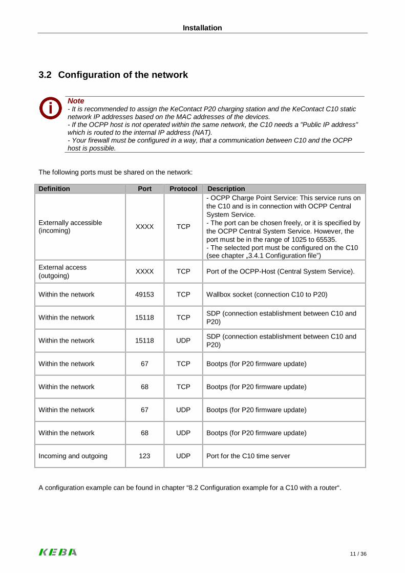
3.2 Configuration of the network
Note- It is recommended to assign the KeContact P20 charging station and the KeContact C10 staticnetwork IP addresses based on the MAC addresses of the devices.- If the OCPP host is not operated within the same network, the C10 needs a "Public IP address"which is routed to the internal IP address (NAT).- Your firewall must be configured in a way, that a communication between C10 and the OCPPhost is possible.
The following ports must be shared on the network:
Definition Port Protocol Description
Externally accessible(incoming) XXXX TCP
- OCPP Charge Point Service: This service runs onthe C10 and is in connection with OCPP CentralSystem Service.- The port can be chosen freely, or it is specified bythe OCPP Central System Service. However, theport must be in the range of 1025 to 65535.- The selected port must be configured on the C10(see chapter „3.4.1 Configuration file”)
External access(outgoing) XXXX TCP Port of the OCPP-Host (Central System Service).
Within the network 49153 TCP Wallbox socket (connection C10 to P20)
Within the network 15118 TCP SDP (connection establishment between C10 andP20)
Within the network 15118 UDP SDP (connection establishment between C10 andP20)
Within the network 67 TCP Bootps (for P20 firmware update)
Within the network 68 TCP Bootps (for P20 firmware update)
Within the network 67 UDP Bootps (for P20 firmware update)
Within the network 68 UDP Bootps (for P20 firmware update)
Incoming and outgoing 123 UDP Port for the C10 time server
A configuration example can be found in chapter “8.2 Configuration example for a C10 with a router“.

Installation
12 / 36
3.2.1 Using more KeContact C10 within the same network
If multiple KeContact C10 are installed within the same network, each C10–P20 group must be commis-sioned one after the other. For each C10 with up to two P20, the commissioning must be carried out as de-scribed in chapter 3.3 Connection establishment.

Installation
13 / 36
3.3 Connection establishment
3.3.1 KeContact C10 installation
Power supply unitC10 is supplied with an external 5VDC power supplyunit.
Preparing the power supply unit
► Slide the correct outlet adapter for your locationinto the power supply unit.
► Prepare the necessary 230V power outlet for thepower supply unit in the near of the C10.
OCPP Host
KeContact C10
Network router/switch
KeContact P20c-serie
KeContact P20c-serie
Internet / LANOCPP communication
! WARNING!Ensure a safe separation from dangerous voltages for Ethernet cable and Power supplycable (e.g. when installing in a switch box / fuse box).

Installation
14 / 36
3.3.2 Commissioning procedure
3.3.2.1 Commissioning the C10 with KeContact P20
Device Description
1 Router Take the router/modem/switch into operation.
2 P20Take the P20 into operation (see P20 Installation manual inchapter Installation).After commissioning, set the DIP-switch DSW2.5 to ON.With this setting, the P20 is capable to communicate with asuperior system (C10).Press the Reset button of the P20 and keep it pressed forabout 1 second. Release the button. The P20 reboots andrecognizes the new DIP-switch settings.
3 P20 The LED indicator flashes green if no RFID function isavailable. Otherwise it flashes blue (for configuration seechapter “3.3.2.3 Deactivating RFID”).
4 RouterIf you have not established a network connection of theP20 during commissioning, install it now between routerand P20.
5 Router Make a network connection between router and C10.
6 C10Take the C10 into operation by inserting the voltage supplyplug (power supply unit) in the PSU socket of the C10. Thismay take 15 minutes the first time. The P20 can autono-mously reboot in this period.
NoteIf necessary, note the P20 serial number before closing the housing cover of the charging station.The serial number is located on the type plate on the bottom right of the charging station.

Installation
15 / 36
3.3.2.2 Configuration of the C10
Device Description
1
C10
Connect an empty USB stick to one of the USB ports of theC10.
2On the C10 the LED LD1 starts to blink green. The processcan be processed quickly, so you might not perceive theflashing.
3
After the process is complete, LD1 will not light if the con-figuration of the C10 was not completed and no connectionto the Central System OCPP service is established.Otherwise, the LD1 will light up again.
4
PC
Disconnect the USB stick and connect it to the PC.
5
Now on the USB stick the following folders are available:
CFGLOGSUPD
The configuration file is in folder CFG. The log files arelocated in folder LOGS and the folder UPD is used for theupdate of the C10.Open the file C10_Seriennummer.conf in folder CFG.Adjust the configuration as described in chapter “3.4.1 Con-figuration file”.
6After adapting the configuration file, save the file and ejectthe USB stick properly.
7
C10
Connect the USB stick again to one of the USB port of theC10.
8 The LED LD1 starts to blink green again.
9Wait until the LD1 either lights continuously or goes out.This may take up to 20 minutes for the first time.
10
If the LD1 lights continuously, the configuration was suc-cessful and a connection to the OCPP Central Systemcould be established.In addition, you can read the status of the C10 on the num-ber of illuminated segments on the P20 wallbox (see chap-ter 3.3.2.1 Commissioning the C10 with KeContact P20).
11If the LD1 is dark, the connection to the OCPP host couldnot be established. Check the configuration (pay attentionto the note) or see chapter „5 Troubleshooting“.
NoteIf you want to transfer the current configuration again onto the USB stick, remove at least theCFG folder and follow the steps 1, 2, and 3 again. So you can check whether the configurationhas been adopted.

Installation
16 / 36
3.3.2.3 Deactivating RFID
NoteIf you have a P20, which has no RFID symbol on the front, the RFID functionality is not available!
IMPORTANT!Make sure that during this configuration, no vehicle is plugged into the P20. Active charging ses-sions will be interrupted.
Device Description
1
P20
Take the P20 autonomously in operation:Deactivate Dip-switch 2.5 (Off) or disconnect the networkconnection between C10 and P20. Alternatively, you canturn off the C10, but this requires later a reboot of the C10which can take 10-15 minutes.Press the Reset button of the P20 and keep it pressed forabout 1 second. Release the button in order to reboot theP20.The P20 lights blue if the RFID functionality is enabled orgreen if the RFID functionality is already deactivated.
Autonomous if Dip-switch 2.5=OFF:
Or autonomous if Dip-switch 2.5=ON but noconnection to C10:
2
Press the Reset button of the P20 and keep it pressed forabout 5 seconds.The P20 should play two acoustic signals during this time.Release the button. Now the P20 flashes green and theRFID functionality is deactivated.
Autonomous if Dip-switch 2.5=OFF:
Or autonomous if Dip-switch 2.5=ON but noconnection to C10:
3 C10
Connect the C10 with the network again or activate Dip-switch 2.5 (ON) again.Press the Reset button of the P20 and keep it pressed forabout 1 second. Release the button in order to reboot theP20.Your P20 connects after a short time with the C10. TheLED bar of P20 flashes according to the status of C10 ei-ther continuous or separated.
Connected with C10 ifDip-switch 2.5=ON andOCPP is online:
Connected with C10 ifDip-switch 2.5=ON andOCPP is offline:

Installation
17 / 36
3.3.2.4 Activating RFID
NoteIf you have a P20, which has no RFID symbol on the front, the RFID functionality is not available!The RFID functionality cannot be activated.
IMPORTANT!Make sure that during this configuration, no vehicle is plugged into the P20. Active charging ses-sions will be interrupted.
Device Description
1
P20
Follow steps 1 and 2 of chapter „3.3.2.3 DeactivatingRFID“.
2Hold the RFID card within 60 seconds after the reset andrestart of the P20 over the RFID symbol. You will hear adouble signal. The RFID card is now the Master RFID card.
3After another 60 seconds, the authorization of the MasterRFID card expires and the P20 will flash blue. The authori-zation by the RFID functionality is now enabled.
4 C10 Follow step 3 of chapter “3.3.2.3 Deactivating RFID“.
3.4 Software installationThe C10 can be configured and used for up to two P20 charging stations. To guarantee a flawless functionplease configure the C10 as described in the following chapters. To avoid failure during the configurationalways eject USB devices properly.
3.4.1 Configuration file
► Start with the configuration as described in chapter „3.3.2.2 Configuration of the C10”.
► Open the folder \CFG in the root directory of the USB stick.
► Open the file C10_serialnumber.conf with an editor (e.g. Notepad++, WordPad).Adapt this file according to the configuration.

Installation
18 / 36
File nameAccording to the file name, the configuration file is valid for one or more C10 units.
File name PurposeC10_Serialnumber.conf This configuration file is read only by those C10 which
has the serial number which is in the file name.Several configuration files can be stored in the CFGfolder and it is thus possible to configure multiple C10'swith the same USB stick.
C10.conf With this configuration file each C10 can be configured(without limitation by the serial number).
Note: Change the filename of C10_Serialnumber.confinto C10.conf, to use the configuration file. Leave onlythe configuration file C10.conf in the /CFG folder, thenseveral C10s are successively provided with the sameconfiguration.
Configuration values
► Edit the configuration file with a standard text editor according to the following information.
Parameter description[/opt/KemoveCPM/etc/modules/hostconnector.properties]
Header for configuration of important OCPP messages pa-rameters.
chargeBoxIdentity= With this parameter you assign a name for the C10, that isshown in the header of each OCPP message in field„chargeBoxIdentity“.
hostconnector.clockSynchMethod= This parameter defines the time synchronization of the C10.The following entries are possible:
· OCPP· Timeserver· None
OCPP: The time information which is transmitted in theOCPP message „bootNotificationResponse“ in field „cur-rentTime“ is used in the C10. Pay attention to the followingformat: e.g. 2015-06-13T12:02:19.000+01:00Timeserver: The time is synchronized via the standard timeserver for Unix-based operating systems.None: There is no time synchronization.
[/opt/KemoveCPM/etc/modules/ocpp.properties]
Header for the configuration of the OCPP Central Systems.
full.useTLS= This parameter specifies whether the connection of OCPPCentral System Service (client) to the C10 (OCPP Charge-Point Service, Server) should be encrypted.Possible values are:
· true· false
Installation
19 / 36
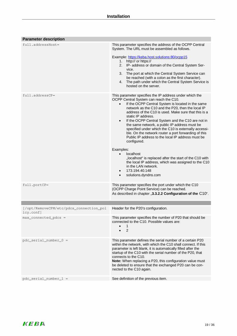
Parameter descriptionfull.addressHost= This parameter specifies the address of the OCPP Central
System. The URL must be assembled as follows.
Example: https://keba.host.solutions:80/ocpp151. http:// or https://2. IP- address or domain of the Central System Ser-
vice.3. The port at which the Central System Service can
be reached (with a colon as the first character).4. The path under which the Central System Service is
hosted on the server.
full.addressCP= This parameter specifies the IP address under which theOCPP Central System can reach the C10.
· If the OCPP Central System is located in the samenetwork as the C10 and the P20, then the local IPaddress of the C10 is used. Make sure that this is astatic IP address.
· If the OCPP Central System and the C10 are not inthe same network, a public IP address must bespecified under which the C10 is externally accessi-ble. On the network router a port forwarding of thisPublic IP address to the local IP address must beconfigured.
Examples:· localhost
„localhost“ is replaced after the start of the C10 withthe local IP address, which was assigned to the C10in the LAN network.
· 173.194.40.148· solutions.dyndns.com
full.portCP= This parameter specifies the port under which the C10(OCPP Charge Point Service) can be reached.As described in chapter „3.3.2.2 Configuration of the C10“.
[/opt/KemoveCPM/etc/pdcs_connection_policy.conf]
Header for the P20’s configuration.
max_connected_pdcs = This parameter specifies the number of P20 that should beconnected to the C10. Possible values are:
· 1· 2
pdc_serial_number_0 = This parameter defines the serial number of a certain P20within the network, with which the C10 shall connect. If thisparameter is left blank, it is automatically filled after thestartup of the C10 with the serial number of the P20, thatconnects to the C10.Note: When replacing a P20, this configuration value mustbe deleted to ensure that the exchanged P20 can be con-nected to the C10 again.
pdc_serial_number_1 = See definition of the previous item.

Installation
20 / 36
3.4.2 Changing the OCPP version
In the delivery state the C10 supports OCPP protocol version 1.5. To change from version 1.5 to 2.0, performthe following steps:
► Perform the steps as described in chapter „4 Software update procedure“.
You need the file „KemoveCPM-OCPP20-setup.keb“ from the internet underwww.kecontact.com/de/downloads .
► After the setup is complete, please check the configuration of the OCPP Central System as de-scribed in chapter „3.3.2.2 Configuration of the C10“ by carrying out the steps to point 5.
NoteTo change the version of the OCPP protocol again from 2.0 to 1.5, please follow the same proce-dure as described above. However, use the file „KemoveCPM-OCPP15-setup.keb“ underwww.kecontact.com/de/downloads.

Software update procedure
21 / 36
4 Software update procedure
In order to bring the C10 communication hub or the P20 charging station to the latest software version, youneed the following: 1x USB stick 1x “keb- file” (as download available under www.kecontact.com/de/downloads ).
► Create a new folder with the name “UPD” on your USB stick or use the UPD folder that was cre-ated during the first commissioning. In addition, when there is a configuration file in the CFG fold-er, the C10 is configured before the update. The configuration is maintained by the software up-date.
► Copy the „keb- file“ into the „UPD“ folder.
► Connect the USB stick to a free USB port of the C10.
► The LED LD1 blinks green as described in chapter „3.3.2.2 Configuration of the C10”:· Wait until the LED LD1 lights up continuously.· If LD1 does not blink or is dark, please see chapter „5 Troubleshooting“.
► After a successful update, you can immediately continue with the operation of your charging sta-tion.

Troubleshooting
22 / 36
5 Troubleshooting
PROBLEM Possible cause - remedyStatus LED does not light up · No voltage supply à Check RCD circuit breaker and
line circuit breaker and switch on if necessary.· Thus, the status LED lights up, a connection to the
P20 and to the OCPP Central system must be es-tablished (successful bootNotificationResponse). àCheck the network connections, or contact yournetwork administrator to ensure that the necessaryfirewall settings have been carried out correctly.
Connection C10 – RouterConnection Router – P20Connection Router – Internet (OCPP)
· Defectiveà please contact your service partner.
Status LED LD1 flashes though no USB stickis connected.
· The USB stick was disconnected too early from theC10: Check the configuration by connecting an emp-ty USB stick to the C10. Thereafter LD1 will stopflashing.
Status LED LD1 does not stop to flash. · If the LED LD1 is still flashing after 30 minutes, re-start the C10 by disconnecting the power supply andreconnecting it again.
Updating the configuration is not possible · Was the USB stick properly ejected?· Format the USB stick and repeat the configuration
procedure (3.3.2.2 Configuration of the C10).· Errors in the configuration fileà Check the settings
and the syntax. Check the last entry in the Log fileconfiguration.log in the folder LOGS on the USBstick.
· Wrong update procedure à Follow the exact proce-dure steps given in chapter 4 Software updateprocedure.
For further information, please see our FAQlist underhttp://www.kecontact.com/de/downloads/
QR code to FAQs

Maintenance
23 / 36
6 Maintenance
6.1 Cleaning
Do not open the KeContact C10 main unit or the Power supply unit!The devices are maintenance free and have no parts inside that require cleaning or regularmaintenance.
► If necessary, carefully clean the housing parts using a moist cloth.
6.2 Service partner
For questions or problems please contact your service partner (e.g. the executive electrical installation com-pany).
Before contacting your service partner:· Check the troubleshooting measures in chapter „5 Troubleshooting“.· Make note of model version and serial number (type plate at the left side of the C10).

Further technical information
24 / 36
7 Further technical information
7.1 Technical data
Electrical data (C10 main unit)Nominal current: <1A
Mains voltage (Europe): 5VDC
IP protection rating for device: IP20 (for indoor use only!)
Connectors
Ethernet port: RJ45
USB ports: 2x Type A
Power supply: USB micro
Mechanical dataDimensions (W x H x D): 71,5 x 104,5 x 62 mm
Environmental conditionsOperating temperature: 5°C to +40°C
Storage temperature range: -25°C to +70°C
Speed of temperature change: max. 0.5°C /min
Permitted relative air humidity: 5% to 95% non-condensing
Altitude: max. 2000 m above sea level
Standards and regulations2004/108/EC Electromagnetic Compatibility Directive
EN 55022:2010 Information technology equipment - Radio disturbance characteristics –Limits and methods of measurement
EN 55024:2010 Information technology equipment - Immunity characteristics –Limits and methods of measurement
NoteFor detailed technical information about the power supply unit please see the data sheet in chap-ter „8 Appendix“.

Further technical information
25 / 36
7.2 Dimensions
Housing dimensions in millimeters
The inserted SD card and the USB plug increase the height to approximately 110mm.Additional free space for the USB stick is required at the bottom side.

Appendix
26 / 36
8 Appendix
8.1 Data sheet power supply unit

Appendix
27 / 36

Appendix
28 / 36
8.2 Configuration example for a C10 with a router
For the operation of a KeContact C10 connected with up to 2 KeContact P20 (c-series) wallboxes you need:· Router· USB stick· Authorization to connect to a OCPP host and the URL of OCPP hosts.
Overview of the required components
The C10 will automatically detect all connected P20 within the Ethernet network. All P20 within the networkare updated to the P20 firmware version that is stored in the C10.
It is not possible to establish a connection between C10 and OCPP-host if no P20 is connected.
► Before you begin with configuring the C10 and the network, please update the C10 to the latestavailable software version (details see chapter “4 Software update procedure”).
GSM/LAN

Appendix
29 / 36
8.2.1 Configuration of the network
a. Configuration of the router
For this example the router XSBox®R6ve was used.The connection of the router to the Internet (GSM or DSL) is not described in this manual and is a pre-requisite. Please use the manual of the router for the corresponding information.
The C10 has to be assigned a static network IP address based on the MAC address. This is necessaryfor port forwarding.
KeContact C10
GUI of the router
MAC address C10
Serial number C10
Ensure that the DHCP server is activated on the router and theselected IP-address is within the DHCP IP pool.

Appendix
30 / 36
The selected port (9080) must be configured on the C10 too. This configuration example is described on thefollowing pages.
From the DHCP IP pool 192.168.123.10 to 192.168.123.50the IP address 192.168.123.11 was selected in this
example.
For the communication from the backend to the C10 aport forwarding on the router is required. The port mustbe selected within the range from 1025 to 65535 (in thisexample: port 9080).

Appendix
31 / 36
b. Commissioning the C10 with the KeContact P20
► Write down if necessary the P20 serial number before closing the housing cover of your chargingstation. The serial number is printed on the type plate at the bottom right of the charging station.In this example 15025563.
► Take the P20 into operation (see P20 Installation manual).· After commissioning, set the DIP-switch DSW2.5 to ON.
With this setting, the P20 is capable to communicate with a superior system (C10).· Press the Reset button of the P20 and keep it pressed for about 1 second (until signal tone).· Release the button.· The P20 reboots and recognizes the new DIP-switch settings.
c. Configuration of the C10
► Follow the instructions in chapter “3.3.2.2 Configuration of the C10”.
After completing the configuration procedure there is a configuration file in the folder "CFG",which contains the C10 serial number in its file name.
Appendix
32 / 36
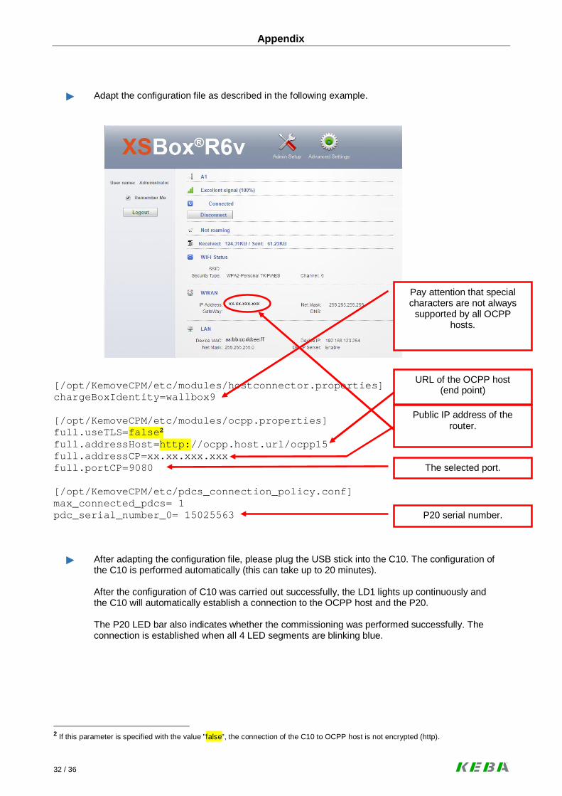
► Adapt the configuration file as described in the following example.
[/opt/KemoveCPM/etc/modules/hostconnector.properties]chargeBoxIdentity=wallbox9
[/opt/KemoveCPM/etc/modules/ocpp.properties]full.useTLS=false2
full.addressHost=http://ocpp.host.url/ocpp15full.addressCP=xx.xx.xxx.xxxfull.portCP=9080
[/opt/KemoveCPM/etc/pdcs_connection_policy.conf]max_connected_pdcs= 1pdc_serial_number_0= 15025563
► After adapting the configuration file, please plug the USB stick into the C10. The configuration ofthe C10 is performed automatically (this can take up to 20 minutes).
After the configuration of C10 was carried out successfully, the LD1 lights up continuously andthe C10 will automatically establish a connection to the OCPP host and the P20.
The P20 LED bar also indicates whether the commissioning was performed successfully. Theconnection is established when all 4 LED segments are blinking blue.
2 If this parameter is specified with the value "false", the connection of the C10 to OCPP host is not encrypted (http).
Public IP address of therouter.
P20 serial number.
The selected port.
URL of the OCPP host(end point)
Pay attention that specialcharacters are not always
supported by all OCPPhosts.

Appendix
33 / 36
Final configuration example:
► If the C10 does not connect to the OCPP server, please check the configuration on any errors inthe settings.
► You can check via the following Internet address if the C10 has established a connection to theInternet.
www.CanYouSeeMe.org
IP address:192.168.123.11
SN: 16157399
http.//ocpp.host.url/ocpp15
Public IP address:xx.xx.xxx.xxx
C10 Port: 9080
IP address:assigned by the
DHCP server
SN:15025563
GSM/LAN

Page left blank

_____________________________________________________________________________
_____________________________________________________________________________
_____________________________________________________________________________
_____________________________________________________________________________
_____________________________________________________________________________
_____________________________________________________________________________
_____________________________________________________________________________
_____________________________________________________________________________
_____________________________________________________________________________
_____________________________________________________________________________
_____________________________________________________________________________
_____________________________________________________________________________
_____________________________________________________________________________
_____________________________________________________________________________
_____________________________________________________________________________
_____________________________________________________________________________
_____________________________________________________________________________
_____________________________________________________________________________
_____________________________________________________________________________
_____________________________________________________________________________
_____________________________________________________________________________
_____________________________________________________________________________
_____________________________________________________________________________
_____________________________________________________________________________
_____________________________________________________________________________
_____________________________________________________________________________


![KeContact P20 Installation manual - The Mobility House€¦ · · 2016-05-30KEBA AG, Postfach 111, Gewerbepark Urfahr, ... KeContact P20 Use of this manual ... [S] is used for authorizing](https://static.fdocuments.us/doc/165x107/5ae548ed7f8b9a7b218f830a/kecontact-p20-installation-manual-the-mobility-house-2016-05-30keba-ag-postfach.jpg)