
KDC 40 4-CM DC ION SOURCE MANUAL Supplement … · The Kaufman & Robinson, Inc., KRI® KDC 40 Ion...
58
KDC 40 4-CM DC ION SOURCE MANUAL Supplement for MICRODISHED ™ MOLYBDENUM ION OPTICS Kaufman & Robinson, Inc. 1330 Blue Spruce Drive Fort Collins, Colorado 80524 Tel: 970-495-0187, Fax: 970-484-9350 Internet: www.ionsources.com Copyright © 2011 by Kaufman & Robinson, Inc. All rights reserved. No part of this publication may be reproduced without written permission.
Transcript of KDC 40 4-CM DC ION SOURCE MANUAL Supplement … · The Kaufman & Robinson, Inc., KRI® KDC 40 Ion...

KDC 40 4-CM DC ION SOURCE MANUAL
Supplement for
MICRODISHED™ MOLYBDENUM
ION OPTICS
Kaufman & Robinson, Inc. 3 1330 Blue Spruce DriveF Fort Collins, Colorado 80524 Tel: 970-495-0187, Fax: 970-484-9350 Internet: www.ionsources.com Copyright © 2011 by Kaufman & Robinson, Inc. All rights reserved. No part of this publication may be reproduced without written permission. June 2011, Version 2

CONTENTS 1 _______________________________________________________
________________________________________________________________ Copyright © 2008 by Kaufman & Robinson, Inc., 1306 Blue Spruce Drive, Unit A, Fort Collins, CO 80524 Tel: 970-495-0187, Fax: 970-484-9350, Internet: www.ionsources.com
CONTENTS 1 Safety.............................................................................................................1-1 2 Specifications.................................................................................................2-1 3 Performance ..................................................................................................3-1 3.1 Gas Flow ..........................................................................................3-1 3.2 Electron-Backstreaming Limit...........................................................3-1
3.3 Maximum Ion Beam Current ............................................................3-2 3.4 Ion Beam Profiles.............................................................................3-3
4 Maintenance ..................................................................................................4-1 4.1 The Need for Maintenance................................................................4-1 4.2 Disassembly.....................................................................................4-2 4.21 Remove ion optics nuts .......................................................4-2 4.22 Remove magnet assembly ..................................................4-2 4.23 Remove insulators and sputter shield..................................4-2 4.24 Remove screen-grid support ...............................................4-3 4.25 Remove screen grid ............................................................4-3 4.26 Remove accelerator ............................................................4-3 4.27 Remove accelerator-grid support ........................................4-3 4.3 Clean the ion-optics parts.................................................................4-3
4.31 Grids....................................................................................4-3 4.32 Grid supports .......................................................................4-4 4.33 Ion-optics support ................................................................4-4 4.4 Selection of Focusing or Divergent Configuration ............................4-4 4.5 Re-assembly of the Ion Optics .........................................................4-4 4.51 Ion-optics support ................................................................4-5 4.52 Replace the accelerator-grid support...................................4-5 4.53 Replace the accelerator grid................................................4-5 4.54 Install new ball insulators.....................................................4-6 4.55 Replace the screen grid.......................................................4-6 4.56 Replace the screen-grid support..........................................4-6 4.57 Replace sputter shield and 10-32 insulators........................4-6 4.58 Replace magnet assembly ..................................................4-6 4.59 Tighten ion-optics screws .....................................................4-7 4.6 Spares..............................................................................................4-7 5 Warranty ........................................................................................................5-1
CONTENTS 2 _______________________________________________________
________________________________________________________________ Copyright © 2008 by Kaufman & Robinson, Inc., 1306 Blue Spruce Drive, Unit A, Fort Collins, CO 80524 Tel: 970-495-0187, Fax: 970-484-9350, Internet: www.ionsources.com
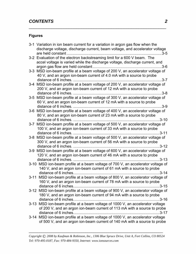
Figures 3-1 Variation in ion beam current for a variation in argon gas flow when the discharge voltage, discharge current, beam voltage, and accelerator voltage are held constant ........................................................................................3-5 3-2 Evaluation of the electron backstreaming limit for a 600 V beam. The accel voltage is varied while the discharge voltage, discharge current, and argon gas flow are held constant ................................................................3-6 3-3 MSD ion-beam profile at a beam voltage of 200 V, an accelerator voltage of
40 V, and an argon ion-beam current of 4.0 mA with a source to probe distance of 6 inches. ..................................................................................3-7
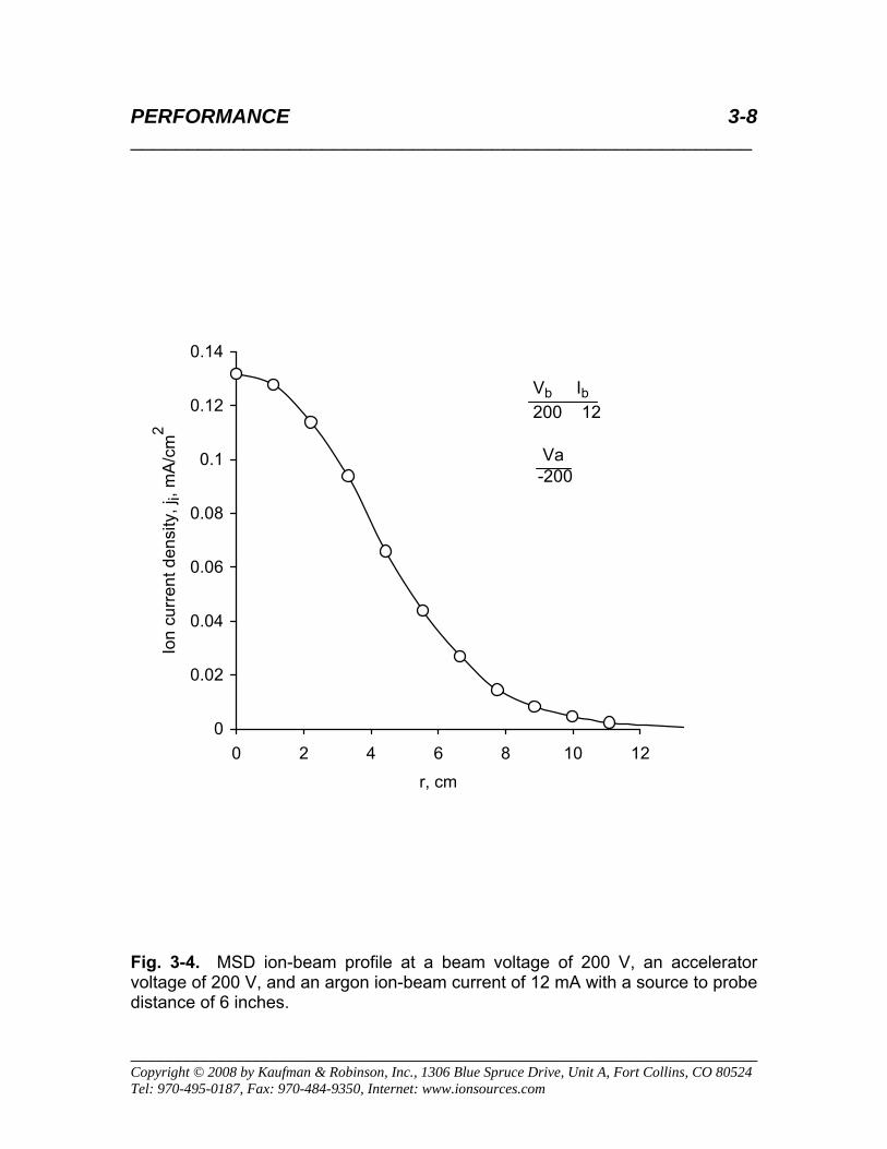
3-4 MSD ion-beam profile at a beam voltage of 200 V, an accelerator voltage of 200 V, and an argon ion-beam current of 12 mA with a source to probe distance of 6 inches. ..................................................................................3-8
3-5 MSD ion-beam profile at a beam voltage of 300 V, an accelerator voltage of 60 V, and an argon ion-beam current of 12 mA with a source to probe distance of 6 inches. ..................................................................................3-9
3-6 MSD ion-beam profile at a beam voltage of 400 V, an accelerator voltage of 80 V, and an argon ion-beam current of 23 mA with a source to probe distance of 6 inches. ................................................................................3-10
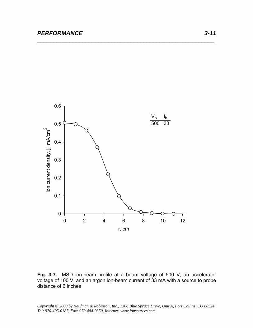
3-7 MSD ion-beam profile at a beam voltage of 500 V, an accelerator voltage of 100 V, and an argon ion-beam current of 33 mA with a source to probe distance of 6 inches. ................................................................................3-11
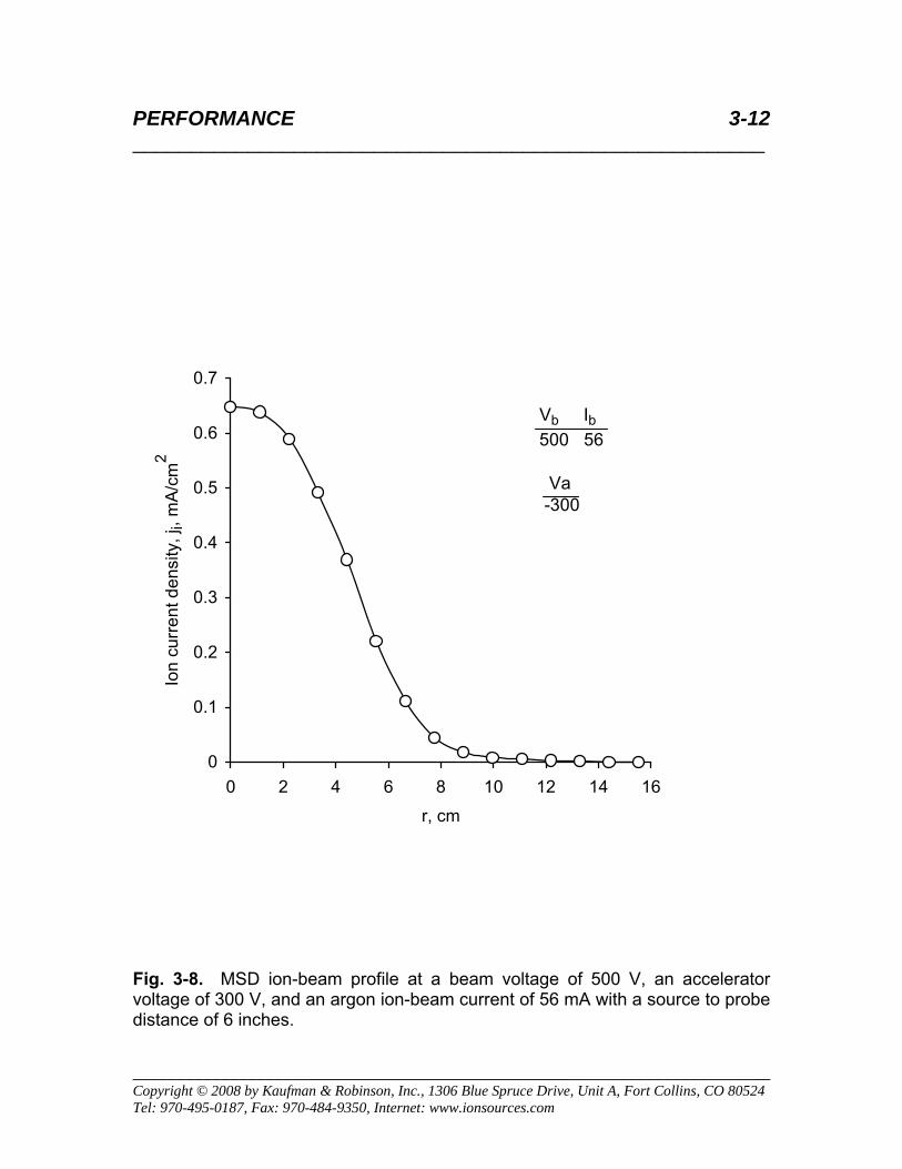
3-8 MSD ion-beam profile at a beam voltage of 500 V, an accelerator voltage of 300 V, and an argon ion-beam current of 56 mA with a source to probe distance of 6 inches. ................................................................................3-12
3-9 MSD ion-beam profile at a beam voltage of 600 V, an accelerator voltage of 120 V, and an argon ion-beam current of 46 mA with a source to probe distance of 6 inches. ................................................................................3-13
3-10 MSD ion-beam profile at a beam voltage of 700 V, an accelerator voltage of 140 V, and an argon ion-beam current of 61 mA with a source to probe distance of 6 inches................................................................................3-14
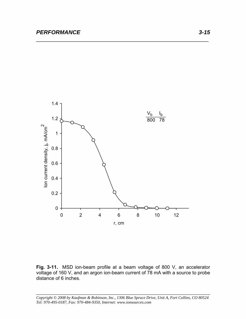
3-11 MSD ion-beam profile at a beam voltage of 800 V, an accelerator voltage of 160 V, and an argon ion-beam current of 78 mA with a source to probe distance of 6 inches................................................................................3-15
3-12 MSD ion-beam profile at a beam voltage of 900 V, an accelerator voltage of 180 V, and an argon ion-beam current of 94 mA with a source to probe distance of 6 inches................................................................................3-16
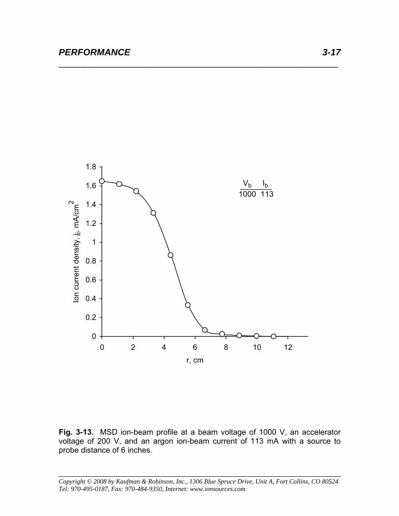
3-13 MSD ion-beam profile at a beam voltage of 1000 V, an accelerator voltage of 200 V, and an argon ion-beam current of 113 mA with a source to probe distance of 6 inches................................................................................3-17
3-14 MSD ion-beam profile at a beam voltage of 1000 V, an accelerator voltage of 500 V, and an argon ion-beam current of 140 mA with a source to probe
CONTENTS 3 _______________________________________________________
________________________________________________________________ Copyright © 2008 by Kaufman & Robinson, Inc., 1306 Blue Spruce Drive, Unit A, Fort Collins, CO 80524 Tel: 970-495-0187, Fax: 970-484-9350, Internet: www.ionsources.com
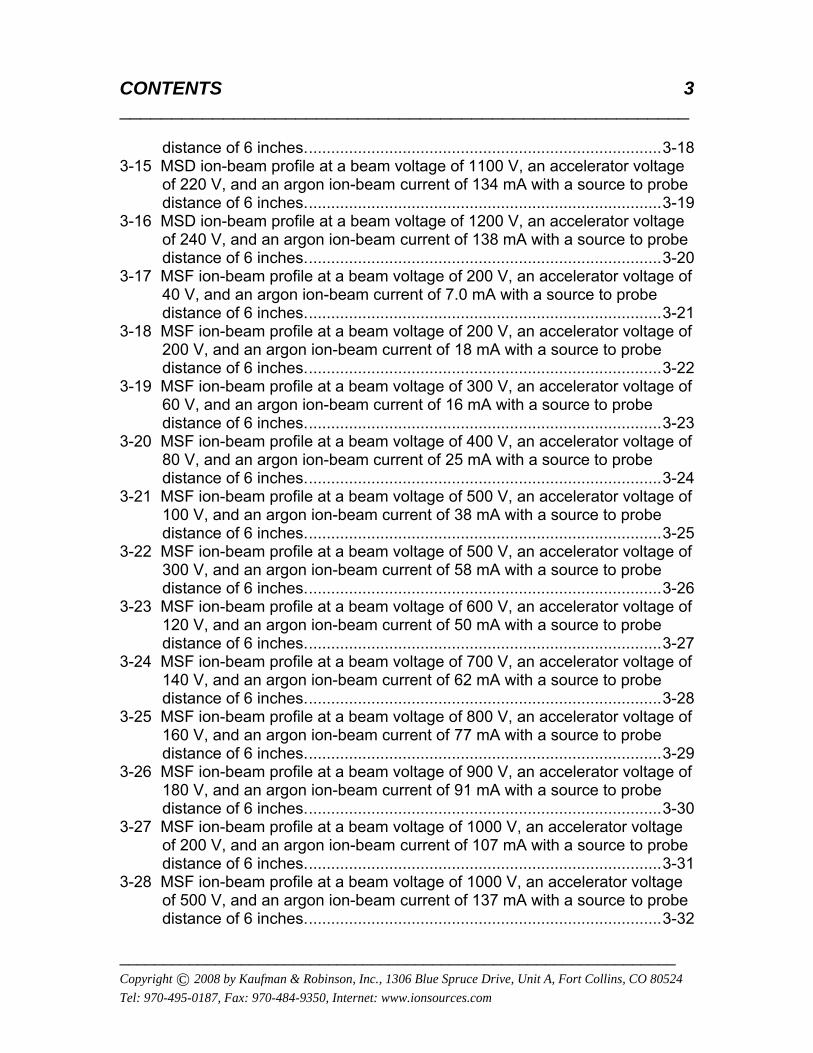
distance of 6 inches................................................................................3-18 3-15 MSD ion-beam profile at a beam voltage of 1100 V, an accelerator voltage
of 220 V, and an argon ion-beam current of 134 mA with a source to probe distance of 6 inches................................................................................3-19
3-16 MSD ion-beam profile at a beam voltage of 1200 V, an accelerator voltage of 240 V, and an argon ion-beam current of 138 mA with a source to probe distance of 6 inches................................................................................3-20
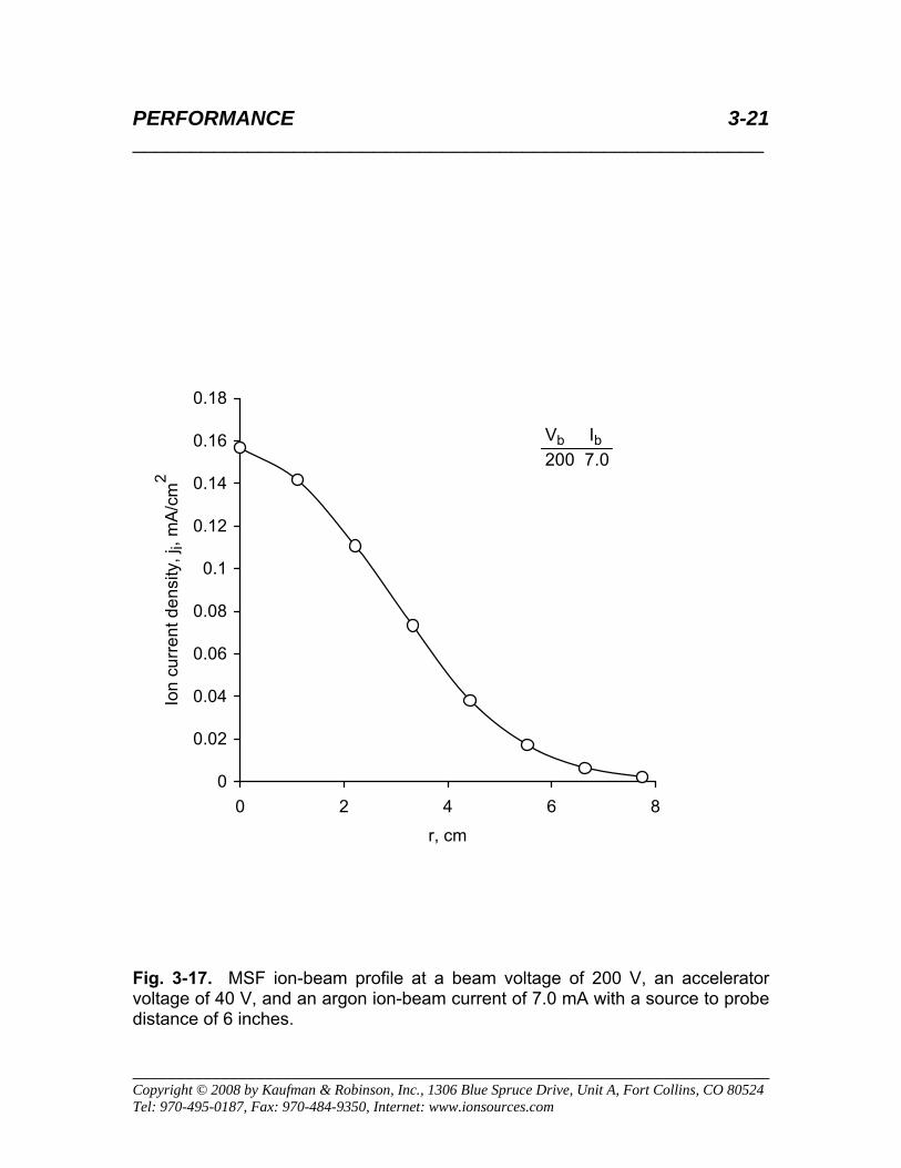
3-17 MSF ion-beam profile at a beam voltage of 200 V, an accelerator voltage of 40 V, and an argon ion-beam current of 7.0 mA with a source to probe distance of 6 inches................................................................................3-21
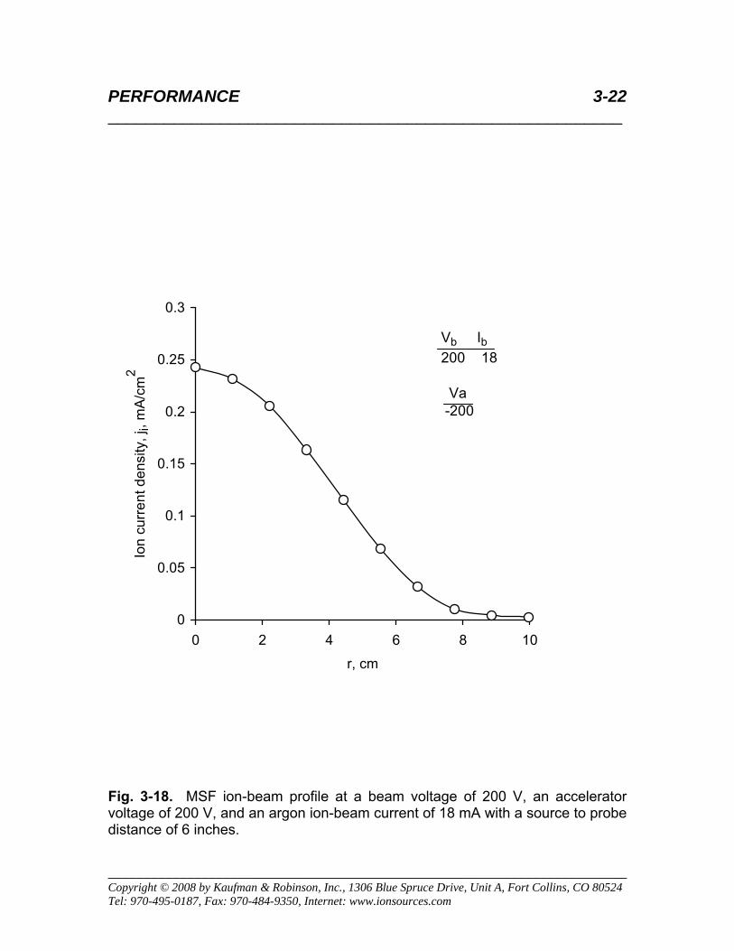
3-18 MSF ion-beam profile at a beam voltage of 200 V, an accelerator voltage of 200 V, and an argon ion-beam current of 18 mA with a source to probe distance of 6 inches................................................................................3-22
3-19 MSF ion-beam profile at a beam voltage of 300 V, an accelerator voltage of 60 V, and an argon ion-beam current of 16 mA with a source to probe distance of 6 inches................................................................................3-23
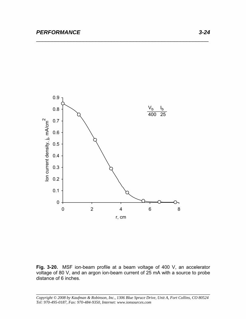
3-20 MSF ion-beam profile at a beam voltage of 400 V, an accelerator voltage of 80 V, and an argon ion-beam current of 25 mA with a source to probe distance of 6 inches................................................................................3-24
3-21 MSF ion-beam profile at a beam voltage of 500 V, an accelerator voltage of 100 V, and an argon ion-beam current of 38 mA with a source to probe distance of 6 inches................................................................................3-25
3-22 MSF ion-beam profile at a beam voltage of 500 V, an accelerator voltage of 300 V, and an argon ion-beam current of 58 mA with a source to probe distance of 6 inches................................................................................3-26
3-23 MSF ion-beam profile at a beam voltage of 600 V, an accelerator voltage of 120 V, and an argon ion-beam current of 50 mA with a source to probe distance of 6 inches................................................................................3-27
3-24 MSF ion-beam profile at a beam voltage of 700 V, an accelerator voltage of 140 V, and an argon ion-beam current of 62 mA with a source to probe distance of 6 inches................................................................................3-28
3-25 MSF ion-beam profile at a beam voltage of 800 V, an accelerator voltage of 160 V, and an argon ion-beam current of 77 mA with a source to probe distance of 6 inches................................................................................3-29
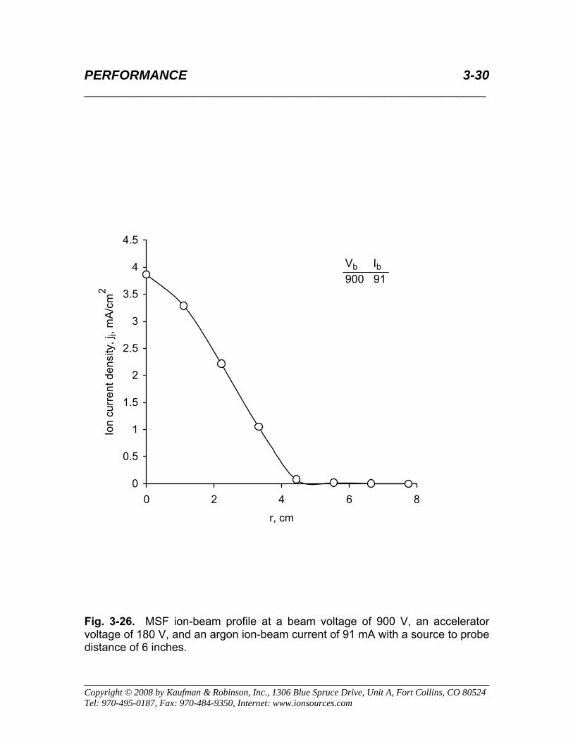
3-26 MSF ion-beam profile at a beam voltage of 900 V, an accelerator voltage of 180 V, and an argon ion-beam current of 91 mA with a source to probe distance of 6 inches................................................................................3-30
3-27 MSF ion-beam profile at a beam voltage of 1000 V, an accelerator voltage of 200 V, and an argon ion-beam current of 107 mA with a source to probe distance of 6 inches................................................................................3-31
3-28 MSF ion-beam profile at a beam voltage of 1000 V, an accelerator voltage of 500 V, and an argon ion-beam current of 137 mA with a source to probe distance of 6 inches................................................................................3-32
CONTENTS 4 _______________________________________________________
________________________________________________________________ Copyright © 2008 by Kaufman & Robinson, Inc., 1306 Blue Spruce Drive, Unit A, Fort Collins, CO 80524 Tel: 970-495-0187, Fax: 970-484-9350, Internet: www.ionsources.com
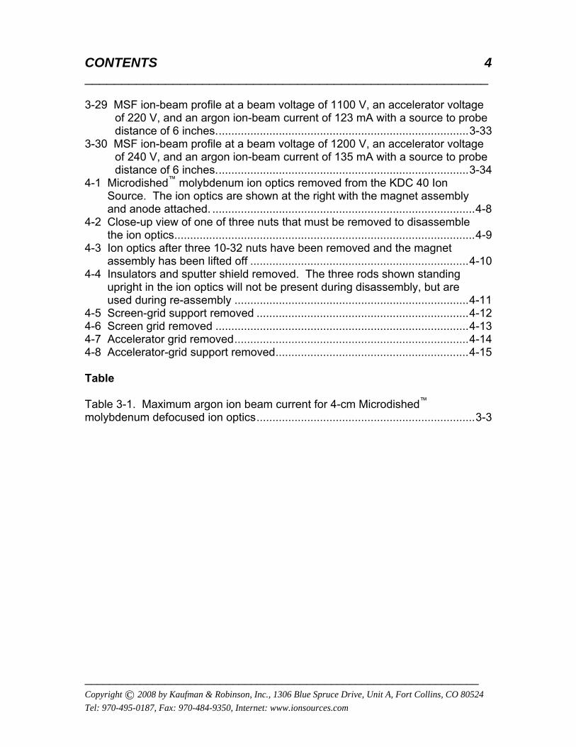
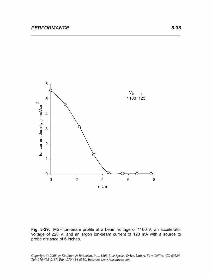
3-29 MSF ion-beam profile at a beam voltage of 1100 V, an accelerator voltage of 220 V, and an argon ion-beam current of 123 mA with a source to probe distance of 6 inches................................................................................3-33
3-30 MSF ion-beam profile at a beam voltage of 1200 V, an accelerator voltage of 240 V, and an argon ion-beam current of 135 mA with a source to probe distance of 6 inches................................................................................3-34
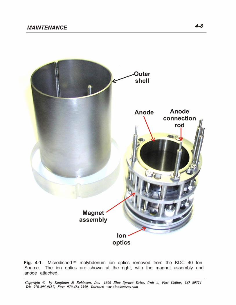
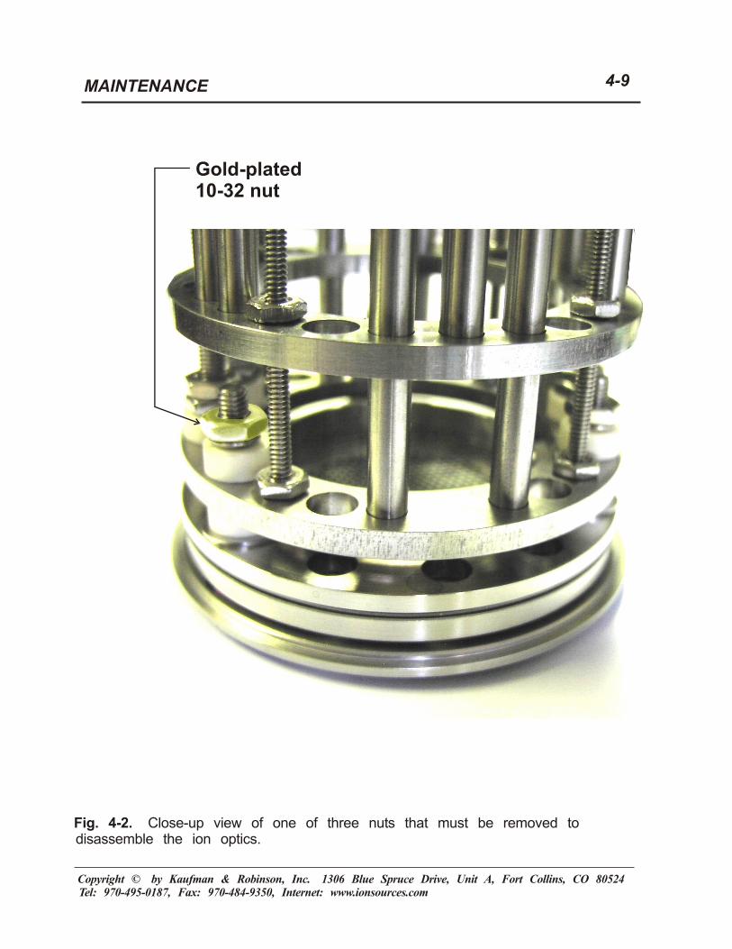
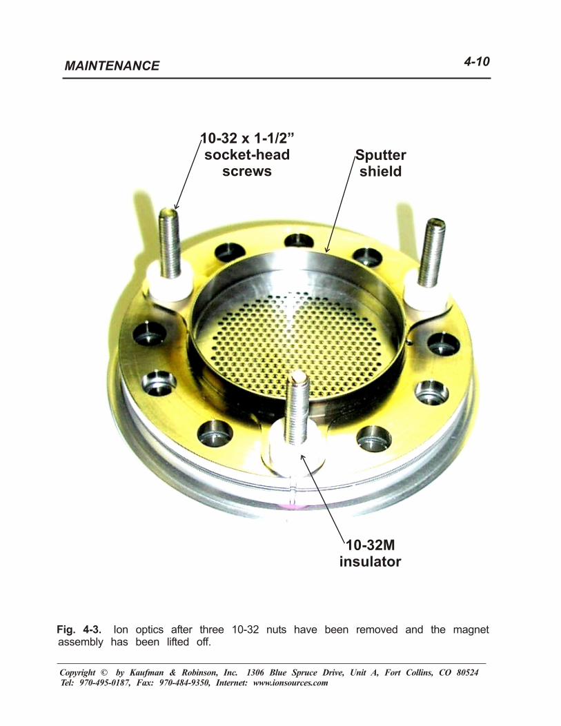
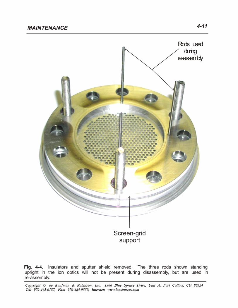
4-1 Microdished™ molybdenum ion optics removed from the KDC 40 Ion Source. The ion optics are shown at the right with the magnet assembly and anode attached. ...................................................................................4-8 4-2 Close-up view of one of three nuts that must be removed to disassemble the ion optics...............................................................................................4-9 4-3 Ion optics after three 10-32 nuts have been removed and the magnet assembly has been lifted off .....................................................................4-10 4-4 Insulators and sputter shield removed. The three rods shown standing upright in the ion optics will not be present during disassembly, but are used during re-assembly ..........................................................................4-11 4-5 Screen-grid support removed ...................................................................4-12 4-6 Screen grid removed ................................................................................4-13 4-7 Accelerator grid removed..........................................................................4-14 4-8 Accelerator-grid support removed.............................................................4-15 Table Table 3-1. Maximum argon ion beam current for 4-cm Microdished™ molybdenum defocused ion optics.....................................................................3-3

SAFETY 1-1 _______________________________________________________
________________________________________________________________________ Copyright © 2008 by Kaufman & Robinson, Inc., 1306 Blue Spruce Drive, Unit A, Fort Collins, CO 80524 Tel: 970-495-0187, Fax: 970-484-9350, Internet: www.ionsources.com
1 SAFETY Only technically qualified personnel should install, maintain, and troubleshoot the equipment described herein. Troubleshooting and maintenance should be carried out only after grounding the components to be worked on and assuring that power cannot be applied to those components while working on them.
SPECIFICATIONS 2-1 _______________________________________________________
________________________________________________________________________ Copyright © 2008 by Kaufman & Robinson, Inc., 1306 Blue Spruce Drive, Unit A, Fort Collins, CO 80524 Tel: 970-495-0187, Fax: 970-484-9350, Internet: www.ionsources.com
2 SPECIFICATIONS The Kaufman & Robinson, Inc., KRI ® KDC 40 Ion Source is a gridded ion source that uses a direct-current (dc) discharge to generate ions. It comes with a variety of ion optics. Separate supplements to the manual for that source cover the detailed performance of the different configurations of the ion optics. This is the supplement for the 4-cm Microdished™ molybdenum ion optics. Microdished™ molybdenum ion optics offer a thir d alternative to the established options of dished m olybdenum ion optic s and pyrolytic graphite ion optics. Microdished™ ion optics can be used to generate collimated, slightly focused, or slightly divergent ion beams, roughly similar to the options available with pyrolytic graphite ion optics. At the same ti me, they have t he ruggedness of dished molybdenum ion optics. Bec ause they use a patented ( U.S. Patent 6,246,162) elastic dishing technology, no dishing step is required during their fabrication and they are comparatively economical to use. These Microdished™ ion optics can be used to generate either a slightly focused ion beam or a slightly divergent ion beam. This switch is accomplished by taking the ion optics apart, turning ov er the a ccelerator-grid support, accelerator grid, screen grid, and screen-grid support, and re-assembling the ion optics . (This means that the screen-grid support becom es the accelerator-grid support, the screen grid becomes the accelerator grid, etc.) In both cases the mean deflec tion of a beamlet (the ions leaving a single aperture) from the axial direction is about 5º. For low-divergence operation of the ion source (usually found at slightly less than the maximum ion-beam current for the beam and accel voltages us ed), the ions leaving a si ngle aperture typically have a distribution range of about ±6º relati ve to the mean direction. This means that the focusing in the slightly focused configuration will offset the normal growth of a collimated beam up to a distance of about 20 cm from the ion source, after which the beam diameter will grow more rapidly. This is also the configuration to use if the maximum current density is desired on the axis of the ion beam. The slightly divergent configurati on should be used when a broader, more uniform coverage is desired. These ion optics can accelerate an ion beam with an argon ion current of more than 113 mA at a beam voltage of 1000 V or more.
PERFORMANCE 3-1 _______________________________________________________
________________________________________________________________________ Copyright © 2008 by Kaufman & Robinson, Inc., 1306 Blue Spruce Drive, Unit A, Fort Collins, CO 80524 Tel: 970-495-0187, Fax: 970-484-9350, Internet: www.ionsources.com
3 PERFORMANCE The experimental performance of different ion optics will vary slightly, due to small differences in construction. Some of the variations may also be due to normal errors in the various measurements, impurities present, or details of the particular installation. Although KRI® personnel have taken great care to assure reproducible performance of the ion optics, there may be some variations from the performance described in this section. The following is a more detailed description of the performance of the KDC 40 Ion Source when Microdished™ molybdenum ion optics are used. It should supplement the more qualitative description in Sections 4.4 through 4.7 in the manual for the KDC 40 Ion Source. 3.1 Gas Flow
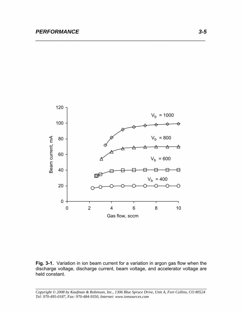
Figure 3-1 shows the variation in ion beam current for a variation in argon gas flow for several different beam voltages when the discharge voltage, discharge current, and accelerator voltage are all held constant for each beam voltage. The operation with the Microdished™ molybdenum ion optics is considered typical for gas flow requirements of the KDC 40 Ion Source, so that Fig. 3-1 is identical to Fig. 4-2 of the ion source manual.
As shown in Fig. 3-1, the optimum gas flow of argon ranges from about 4 sccm at low ion-beam currents to about 6 sccm at ion-beam currents of about 100 mA. For more information concerning optimum gas flow, please read Section 4.4 of the ion source manual.
There is also some effect of the background pressure in the vacuum chamber in which the ion source is installed, due to the backflow of neutrals through the ion optics. The data in Fig. 3-1 were obtained at a low background pressure. The effect of background pressure tends to be small for small ion sources, but Section 4.4 of the ion source manual describes the procedure for obtaining data similar to that in Fig. 3-1 for the user’s vacuum chamber.
3.2 Electron-Backstreaming Limit
The accelerator grid (see Fig. 3-1 in the ion source manual) serves as a barrier to neutralizing electrons, preventing them from flowing backward through the ion optics and giving a false contribution to the indicated ion beam current. Because the potential at the center of an accelerator-grid
PERFORMANCE 3-2 _______________________________________________________
________________________________________________________________________ Copyright © 2008 by Kaufman & Robinson, Inc., 1306 Blue Spruce Drive, Unit A, Fort Collins, CO 80524 Tel: 970-495-0187, Fax: 970-484-9350, Internet: www.ionsources.com
aperture is more positive than the accelerator potential, the accelerator grid must be negative of ground to provide such a barrier.
A sample of the data used to evaluate the backstreaming limit is shown in Fig. 3-2. With the gas flow, discharge voltage, discharge current, and beam voltage (600 V) all held constant, the magnitude of the negative accelerator voltage is reduced. At first there is a slow reduction in indicated ion beam current, because the reduction in negative accelerator voltage results in some reduction in ion-extraction efficiency. As the accelerator grid approaches ground (0 V), however, backstreaming electrons from the neutralizer start flowing back through the ion optics. To avoid this false contribution to indicated ion beam current, the accelerator should be negative of ground by about 100 V or more. To allow for small variations in installation, instrumentation, and operating conditions, an accelerator voltage of 120 V is recommended.
As described in Section 4.5 of the ion source manual, the backstreaming limit has been found to depend almost entirely with the beam voltage. For the Microdished™ molybdenum ion optics, a minimum accelerator voltage equal to 20% of the beam voltage is recommended. For additional background information on the electon-backstreaming limit, see Section 4.5 of the ion source manual.
3.3 Maximum Ion Beam Current
The maximum ion beam current is the maximum value that can be obtained without the direct impingement of energetic ions on the accelerator grid. This maximum beam current is a function of beam and accelerator voltages and is separate from the maximum power limit described in Section 4.3 of the ion source manual. Depending on the operating condition, it is possible to have the ion beam current limited by either the ion optics or the maximum discharge-chamber power. For additional background material on the maximum ion-beam current, see Section 4.6 of the ion source manual.
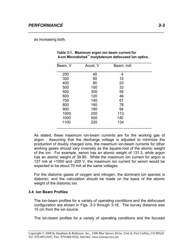
Table 3-1 gives the maximum argon ion beam currents for the 4-cm Microdished™ ion optics over a range of ion beam voltages. The accelerator voltages (negative of ground, as shown in Fig. 3-1 of the ion source manual) are mostly at 20 percent of the beam voltages, as described in the preceding section. The exception is at a beam voltage of 500 V, where an accelerator voltage of 300 V is used. Careful comparison to the maximum beam currents at +600, -120 and +700, -140 will show that increasing the negative accelerator voltage will increase the maximum beam current, but not as much
PERFORMANCE 3-3 _______________________________________________________
________________________________________________________________________ Copyright © 2008 by Kaufman & Robinson, Inc., 1306 Blue Spruce Drive, Unit A, Fort Collins, CO 80524 Tel: 970-495-0187, Fax: 970-484-9350, Internet: www.ionsources.com
as increasing both.
Table 3-1. Maximum argon ion beam current for 4-cm Microdished™ molybdenum defocused ion optics.
_____________________________________________ Beam, V Accel, V Beam, mA _____________________________________________ 200 40 4 300 60 12 400 80 23 500 100 33 500 300 56 600 120 46 700 140 61 800 160 78 900 180 94
1000 200 113 1000 500 140 1100 220 134 _____________________________________________
As stated, these maximum ion-beam currents are for the working gas of argon. Assuming that the discharge voltage is adjusted to minimize the production of doubly charged ions, the maximum ion-beam currents for other working gases should vary inversely as the square-root of the atomic weight of the ion. For example, xenon has an atomic weight of 131.3, while argon has an atomic weight of 39.95. While the maximum ion current for argon is 127 mA at +1000 and -200 V, the maximum ion current for xenon would be expected to be about 70 mA at the same voltages.
For the diatomic gases of oxygen and nitrogen, the dominant ion species is diatomic, and the calculation should be made on the basis of the atomic weight of the diatomic ion.
3.4 Ion Beam Profiles
The ion-beam profiles for a variety of operating conditions and the defocused configuration are shown in Figs. 3-3 through 3-16. The survey distance was 15 cm from the ion source.
The ion-beam profiles for a variety of operating conditions and the focused
PERFORMANCE 3-4 _______________________________________________________
________________________________________________________________________ Copyright © 2008 by Kaufman & Robinson, Inc., 1306 Blue Spruce Drive, Unit A, Fort Collins, CO 80524 Tel: 970-495-0187, Fax: 970-484-9350, Internet: www.ionsources.com
configuration are shown in Figs. 3-17 through 3-30. The survey distance was 15 cm from the ion source.
In selecting an operating condition, the user of the ion source is cautioned against using larger than necessary accelerator voltages to increase the maximum beam current at a given beam voltage. The ion beam tends to diverge more at these larger accelerator voltages so that the gain in current density at the target can be less than expected.
There can also be a contamination concern. Charge-exchange ions fall back on the accelerator grid and cause some sputter contamination from that grid. This contamination is small near the backstreaming limit, but can increase greatly at large negative accelerator voltages. If the ion-source application involved is sensitive to contamination, the user should be very careful about increasing the accelerator voltage more than necessary.
These profiles are corrected for charge-exchange ions. Energetic ions can pass near, and exchange an electron with a low-energy background neutral. This results in a low-energy ion and an energetic neutral that can continue to the target and do most, or all, of the processing that an energetic ion would have done. (The loss of momentum is a much slower process than charge exchange and is usually negligible at the background pressures of ≤0.5 milliTorr at which gridded ion sources are normally operated.1) If a screened probe2 (which excludes charge-exchange ions) is used to check these profiles, current densities slightly less than those shown in the profiles will be obtained. If a planar probe2 is used (which collects the low-energy ions from the surroundings, in addition to energetic ions), current densities slightly greater than those shown in the profiles will be obtained.
Reference 1. MEAN FREE PATH TECH NOTE 2. J. R. Kahn, H. R. Kaufman, R. E. Nethery, R. S. Robinson, and C. M. Shonka, "Low energy End-Hall Ion Source Characterization at Millitorr Pressures," 48th Annual Technical Conference Proceedings of the Society of Vacuum Coaters, pp. 17-22, 2005.
PERFORMANCE 3-5 _______________________________________________________
________________________________________________________________________ Copyright © 2008 by Kaufman & Robinson, Inc., 1306 Blue Spruce Drive, Unit A, Fort Collins, CO 80524 Tel: 970-495-0187, Fax: 970-484-9350, Internet: www.ionsources.com
Fig. 3-1. Variation in ion beam current for a variation in argon gas flow when the discharge voltage, discharge current, beam voltage, and accelerator voltage are held constant.
0
20
40
60
80
100
120
0 2 4 6 8 10
Gas flow, sccm
Beam
cur
rent
, mA
Vb = 1000
Vb = 800
Vb = 600
Vb = 400

PERFORMANCE 3-6 _______________________________________________________
________________________________________________________________________ Copyright © 2008 by Kaufman & Robinson, Inc., 1306 Blue Spruce Drive, Unit A, Fort Collins, CO 80524 Tel: 970-495-0187, Fax: 970-484-9350, Internet: www.ionsources.com
40
41
42
43
44
45
46
47
48
49
50
0 100 200 300 400
Accelerator voltage, volts
Bea
m C
urre
nt, m
A
Vb 600
Fig. 3-2. Evaluation of the electron backstreaming limit for a 600 V beam. The accel voltage is varied while the discharge voltage, discharge current, and argon gas flow are held constant.

PERFORMANCE 3-7 _______________________________________________________
________________________________________________________________________ Copyright © 2008 by Kaufman & Robinson, Inc., 1306 Blue Spruce Drive, Unit A, Fort Collins, CO 80524 Tel: 970-495-0187, Fax: 970-484-9350, Internet: www.ionsources.com
0
0.01
0.02
0.03
0.04
0.05
0.06
0.07
0 2 4 6 8 10 12
r, cm
Ion
curr
ent d
ensi
ty, j
i, m
A/c
m2
Vb Ib200 4.0
Fig. 3-3. MSD ion-beam profile at a beam voltage of 200 V, an accelerator voltage of 40 V, and an argon ion-beam current of 4.0 mA with a source to probe distance of 6 inches.
PERFORMANCE 3-8 _______________________________________________________
________________________________________________________________________ Copyright © 2008 by Kaufman & Robinson, Inc., 1306 Blue Spruce Drive, Unit A, Fort Collins, CO 80524 Tel: 970-495-0187, Fax: 970-484-9350, Internet: www.ionsources.com
0
0.02
0.04
0.06
0.08
0.1
0.12
0.14
0 2 4 6 8 10 12
r, cm
Ion
curr
ent d
ensi
ty, j
i, m
A/c
m2
Vb Ib200 12
Va -200
Fig. 3-4. MSD ion-beam profile at a beam voltage of 200 V, an accelerator voltage of 200 V, and an argon ion-beam current of 12 mA with a source to probe distance of 6 inches.

PERFORMANCE 3-9 _______________________________________________________
________________________________________________________________________ Copyright © 2008 by Kaufman & Robinson, Inc., 1306 Blue Spruce Drive, Unit A, Fort Collins, CO 80524 Tel: 970-495-0187, Fax: 970-484-9350, Internet: www.ionsources.com
0
0.02
0.04
0.06
0.08
0.1
0.12
0.14
0.16
0.18
0.2
0 2 4 6 8 10 12
r, cm
Ion
curr
ent d
ensi
ty, j
i, m
A/c
m2
Vb Ib300 12
Fig. 3-5. MSD ion-beam profile at a beam voltage of 300 V, an accelerator voltage of 60 V, and an argon ion-beam current of 12 mA with a source to probe distance of 6 inches.

PERFORMANCE 3-10 _______________________________________________________
________________________________________________________________________ Copyright © 2008 by Kaufman & Robinson, Inc., 1306 Blue Spruce Drive, Unit A, Fort Collins, CO 80524 Tel: 970-495-0187, Fax: 970-484-9350, Internet: www.ionsources.com
0
0.05
0.1
0.15
0.2
0.25
0.3
0.35
0.4
0 2 4 6 8 10 12
r, cm
Ion
curr
ent d
ensi
ty, j
i, m
A/c
m2
Vb Ib400 23
Fig. 3-6. MSD ion-beam profile at a beam voltage of 400 V, an accelerator voltage of 80 V, and an argon ion-beam current of 23 mA with a source to probe distance of 6 inches.
PERFORMANCE 3-11 _______________________________________________________
________________________________________________________________________ Copyright © 2008 by Kaufman & Robinson, Inc., 1306 Blue Spruce Drive, Unit A, Fort Collins, CO 80524 Tel: 970-495-0187, Fax: 970-484-9350, Internet: www.ionsources.com
0
0.1
0.2
0.3
0.4
0.5
0.6
0 2 4 6 8 10 12
r, cm
Ion
curr
ent d
ensi
ty, j
i, m
A/c
m2
Vb Ib500 33
Fig. 3-7. MSD ion-beam profile at a beam voltage of 500 V, an accelerator voltage of 100 V, and an argon ion-beam current of 33 mA with a source to probe distance of 6 inches
PERFORMANCE 3-12 _______________________________________________________
________________________________________________________________________ Copyright © 2008 by Kaufman & Robinson, Inc., 1306 Blue Spruce Drive, Unit A, Fort Collins, CO 80524 Tel: 970-495-0187, Fax: 970-484-9350, Internet: www.ionsources.com
0
0.1
0.2
0.3
0.4
0.5
0.6
0.7
0 2 4 6 8 10 12 14 16
r, cm
Ion
curr
ent d
ensi
ty, j
i, m
A/c
m2
Vb Ib500 56
Va -300
Fig. 3-8. MSD ion-beam profile at a beam voltage of 500 V, an accelerator voltage of 300 V, and an argon ion-beam current of 56 mA with a source to probe distance of 6 inches.

PERFORMANCE 3-13 _______________________________________________________
________________________________________________________________________ Copyright © 2008 by Kaufman & Robinson, Inc., 1306 Blue Spruce Drive, Unit A, Fort Collins, CO 80524 Tel: 970-495-0187, Fax: 970-484-9350, Internet: www.ionsources.com
0
0.1
0.2
0.3
0.4
0.5
0.6
0.7
0.8
0.9
1
0 2 4 6 8 10 12
r, cm
Ion
curr
ent d
ensi
ty, j
i, m
A/c
m2
Vb Ib600 46
Fig. 3-9. MSD ion-beam profile at a beam voltage of 600 V, an accelerator voltage of 120 V, and an argon ion-beam current of 46 mA with a source to probe distance of 6 inches.

PERFORMANCE 3-14 _______________________________________________________
________________________________________________________________________ Copyright © 2008 by Kaufman & Robinson, Inc., 1306 Blue Spruce Drive, Unit A, Fort Collins, CO 80524 Tel: 970-495-0187, Fax: 970-484-9350, Internet: www.ionsources.com
0
0.1
0.2
0.3
0.4
0.5
0.6
0.7
0.8
0.9
1
0 2 4 6 8 10 12
r, cm
Ion
curr
ent d
ensi
ty, j
i, m
A/c
m2
Vb Ib700 61
Fig. 3-10. MSD ion-beam profile at a beam voltage of 700 V, an accelerator voltage of 140 V, and an argon ion-beam current of 61 mA with a source to probe distance of 6 inches.
PERFORMANCE 3-15 _______________________________________________________
________________________________________________________________________ Copyright © 2008 by Kaufman & Robinson, Inc., 1306 Blue Spruce Drive, Unit A, Fort Collins, CO 80524 Tel: 970-495-0187, Fax: 970-484-9350, Internet: www.ionsources.com
0
0.2
0.4
0.6
0.8
1
1.2
1.4
0 2 4 6 8 10 12
r, cm
Ion
curr
ent d
ensi
ty, j
i, m
A/cm
2
Vb Ib800 78
Fig. 3-11. MSD ion-beam profile at a beam voltage of 800 V, an accelerator voltage of 160 V, and an argon ion-beam current of 78 mA with a source to probe distance of 6 inches.

PERFORMANCE 3-16 _______________________________________________________
________________________________________________________________________ Copyright © 2008 by Kaufman & Robinson, Inc., 1306 Blue Spruce Drive, Unit A, Fort Collins, CO 80524 Tel: 970-495-0187, Fax: 970-484-9350, Internet: www.ionsources.com
0
0.2
0.4
0.6
0.8
1
1.2
1.4
1.6
0 2 4 6 8 10 12
r, cm
Ion
curr
ent d
ensi
ty, j
i, m
A/c
m2
Vb Ib900 94
Fig. 3-12. MSD ion-beam profile at a beam voltage of 900 V, an accelerator voltage of 180 V, and an argon ion-beam current of 94 mA with a source to probe distance of 6 inches.
PERFORMANCE 3-17 _______________________________________________________
________________________________________________________________________ Copyright © 2008 by Kaufman & Robinson, Inc., 1306 Blue Spruce Drive, Unit A, Fort Collins, CO 80524 Tel: 970-495-0187, Fax: 970-484-9350, Internet: www.ionsources.com
0
0.2
0.4
0.6
0.8
1
1.2
1.4
1.6
1.8
0 2 4 6 8 10 12
r, cm
Ion
curr
ent d
ensi
ty, j
i, m
A/c
m2
Vb Ib1000 113
Fig. 3-13. MSD ion-beam profile at a beam voltage of 1000 V, an accelerator voltage of 200 V, and an argon ion-beam current of 113 mA with a source to probe distance of 6 inches.

PERFORMANCE 3-18 _______________________________________________________
________________________________________________________________________ Copyright © 2008 by Kaufman & Robinson, Inc., 1306 Blue Spruce Drive, Unit A, Fort Collins, CO 80524 Tel: 970-495-0187, Fax: 970-484-9350, Internet: www.ionsources.com
0
0.2
0.4
0.6
0.8
1
1.2
1.4
1.6
1.8
2
0 5 10 1
r, cm
Ion
curr
ent d
ensi
ty, j
i, m
A/c
m2
Vb Ib1000 140
Va -500
5
Fig. 3-14. MSD ion-beam profile at a beam voltage of 1000 V, an accelerator voltage of 500 V, and an argon ion-beam current of 140 mA with a source to probe distance of 6 inches.

PERFORMANCE 3-19 _______________________________________________________
________________________________________________________________________ Copyright © 2008 by Kaufman & Robinson, Inc., 1306 Blue Spruce Drive, Unit A, Fort Collins, CO 80524 Tel: 970-495-0187, Fax: 970-484-9350, Internet: www.ionsources.com
0
0.5
1
1.5
2
2.5
0 2 4 6 8 10 12
r, cm
Ion
curr
ent d
ensi
ty, j
i, m
A/c
m2
Vb Ib1100 134
Fig. 3-15. MSD ion-beam profile at a beam voltage of 1100 V, an accelerator voltage of 220 V, and an argon ion-beam current of 134 mA with a source to probe distance of 6 inches.

PERFORMANCE 3-20 _______________________________________________________
________________________________________________________________________ Copyright © 2008 by Kaufman & Robinson, Inc., 1306 Blue Spruce Drive, Unit A, Fort Collins, CO 80524 Tel: 970-495-0187, Fax: 970-484-9350, Internet: www.ionsources.com
0
0.5
1
1.5
2
2.5
0 2 4 6 8 10 12
r, cm
Ion
curr
ent d
ensi
ty, j
i, m
A/c
m2
Vb Ib1200 138
Fig. 3-16. MSD ion-beam profile at a beam voltage of 1200 V, an accelerator voltage of 240 V, and an argon ion-beam current of 138 mA with a source to probe distance of 6 inches.
PERFORMANCE 3-21 _______________________________________________________
________________________________________________________________________ Copyright © 2008 by Kaufman & Robinson, Inc., 1306 Blue Spruce Drive, Unit A, Fort Collins, CO 80524 Tel: 970-495-0187, Fax: 970-484-9350, Internet: www.ionsources.com
0
0.02
0.04
0.06
0.08
0.1
0.12
0.14
0.16
0.18
0 2 4 6 8
r, cm
Ion
curr
ent d
ensi
ty, j
i, m
A/c
m2
Vb Ib200 7.0
Fig. 3-17. MSF ion-beam profile at a beam voltage of 200 V, an accelerator voltage of 40 V, and an argon ion-beam current of 7.0 mA with a source to probe distance of 6 inches.
PERFORMANCE 3-22 _______________________________________________________
________________________________________________________________________ Copyright © 2008 by Kaufman & Robinson, Inc., 1306 Blue Spruce Drive, Unit A, Fort Collins, CO 80524 Tel: 970-495-0187, Fax: 970-484-9350, Internet: www.ionsources.com
0
0.05
0.1
0.15
0.2
0.25
0.3
0 2 4 6 8 10
r, cm
Ion
curr
ent d
ensi
ty, j
i, m
A/c
m2
Vb Ib200 18
Va -200
Fig. 3-18. MSF ion-beam profile at a beam voltage of 200 V, an accelerator voltage of 200 V, and an argon ion-beam current of 18 mA with a source to probe distance of 6 inches.

PERFORMANCE 3-23 _______________________________________________________
________________________________________________________________________ Copyright © 2008 by Kaufman & Robinson, Inc., 1306 Blue Spruce Drive, Unit A, Fort Collins, CO 80524 Tel: 970-495-0187, Fax: 970-484-9350, Internet: www.ionsources.com
0
0.05
0.1
0.15
0.2
0.25
0.3
0.35
0.4
0.45
0.5
0 2 4 6 8
r, cm
Ion
curr
ent d
ensi
ty, j
i, m
A/c
m2
Vb Ib300 16
Fig. 3-19. MSF ion-beam profile at a beam voltage of 300 V, an accelerator voltage of 60 V, and an argon ion-beam current of 16 mA with a source to probe distance of 6 inches.
PERFORMANCE 3-24 _______________________________________________________
________________________________________________________________________ Copyright © 2008 by Kaufman & Robinson, Inc., 1306 Blue Spruce Drive, Unit A, Fort Collins, CO 80524 Tel: 970-495-0187, Fax: 970-484-9350, Internet: www.ionsources.com
0
0.1
0.2
0.3
0.4
0.5
0.6
0.7
0.8
0.9
0 2 4 6 8
r, cm
Ion
curr
ent d
ensi
ty, j
i, m
A/c
m2
Vb Ib400 25
Fig. 3-20. MSF ion-beam profile at a beam voltage of 400 V, an accelerator voltage of 80 V, and an argon ion-beam current of 25 mA with a source to probe distance of 6 inches.

PERFORMANCE 3-25 _______________________________________________________
________________________________________________________________________ Copyright © 2008 by Kaufman & Robinson, Inc., 1306 Blue Spruce Drive, Unit A, Fort Collins, CO 80524 Tel: 970-495-0187, Fax: 970-484-9350, Internet: www.ionsources.com
0
0.2
0.4
0.6
0.8
1
1.2
1.4
0 2 4 6 8
r, cm
Ion
curr
ent d
ensi
ty, j
i, m
A/c
m2
Vb Ib500 38
Fig. 3-21. MSF ion-beam profile at a beam voltage of 500 V, an accelerator voltage of 100 V, and an argon ion-beam current of 38 mA with a source to probe distance of 6 inches.

PERFORMANCE 3-26 _______________________________________________________
________________________________________________________________________ Copyright © 2008 by Kaufman & Robinson, Inc., 1306 Blue Spruce Drive, Unit A, Fort Collins, CO 80524 Tel: 970-495-0187, Fax: 970-484-9350, Internet: www.ionsources.com
0
0.2
0.4
0.6
0.8
1
1.2
1.4
0 2 4 6 8 10
r, cm
Ion
curr
ent d
ensi
ty, j
i, m
A/c
m2
Vb Ib500 58
Va -300
Fig. 3-22. MSF ion-beam profile at a beam voltage of 500 V, an accelerator voltage of 300 V, and an argon ion-beam current of 58 mA with a source to probe distance of 6 inches.

PERFORMANCE 3-27 _______________________________________________________
________________________________________________________________________ Copyright © 2008 by Kaufman & Robinson, Inc., 1306 Blue Spruce Drive, Unit A, Fort Collins, CO 80524 Tel: 970-495-0187, Fax: 970-484-9350, Internet: www.ionsources.com
0
0.2
0.4
0.6
0.8
1
1.2
1.4
1.6
1.8
2
0 2 4 6 8
r, cm
Ion
curr
ent d
ensi
ty, j
i, m
A/c
m2
Vb Ib600 50
Fig. 3-23. MSF ion-beam profile at a beam voltage of 600 V, an accelerator voltage of 120 V, and an argon ion-beam current of 50 mA with a source to probe distance of 6 inches.

PERFORMANCE 3-28 _______________________________________________________
________________________________________________________________________ Copyright © 2008 by Kaufman & Robinson, Inc., 1306 Blue Spruce Drive, Unit A, Fort Collins, CO 80524 Tel: 970-495-0187, Fax: 970-484-9350, Internet: www.ionsources.com
0
0.5
1
1.5
2
2.5
3
0 2 4 6 8
r, cm
Ion
curr
ent d
ensi
ty, j
i, m
A/c
m2
Vb Ib700 62
Fig. 3-24. MSF ion-beam profile at a beam voltage of 700 V, an accelerator voltage of 140 V, and an argon ion-beam current of 62 mA with a source to probe distance of 6 inches.

PERFORMANCE 3-29 _______________________________________________________
________________________________________________________________________ Copyright © 2008 by Kaufman & Robinson, Inc., 1306 Blue Spruce Drive, Unit A, Fort Collins, CO 80524 Tel: 970-495-0187, Fax: 970-484-9350, Internet: www.ionsources.com
0
0.5
1
1.5
2
2.5
3
3.5
0 2 4 6 8
r, cm
Ion
curr
ent d
ensi
ty, j
i, m
A/cm
2
Vb Ib800 77
Fig. 3-25. MSF ion-beam profile at a beam voltage of 800 V, an accelerator voltage of 160 V, and an argon ion-beam current of 77 mA with a source to probe distance of 6 inches.
PERFORMANCE 3-30 _______________________________________________________
________________________________________________________________________ Copyright © 2008 by Kaufman & Robinson, Inc., 1306 Blue Spruce Drive, Unit A, Fort Collins, CO 80524 Tel: 970-495-0187, Fax: 970-484-9350, Internet: www.ionsources.com
0
0.5
1
1.5
2
2.5
3
3.5
4
4.5
0 2 4 6 8
r, cm
Ion
curr
ent d
ensi
ty, j
i, m
A/c
m2
Vb Ib900 91
Fig. 3-26. MSF ion-beam profile at a beam voltage of 900 V, an accelerator voltage of 180 V, and an argon ion-beam current of 91 mA with a source to probe distance of 6 inches.

PERFORMANCE 3-31 _______________________________________________________
________________________________________________________________________ Copyright © 2008 by Kaufman & Robinson, Inc., 1306 Blue Spruce Drive, Unit A, Fort Collins, CO 80524 Tel: 970-495-0187, Fax: 970-484-9350, Internet: www.ionsources.com
0
0.5
1
1.5
2
2.5
3
3.5
4
4.5
5
0 2 4 6 8
r, cm
Ion
curr
ent d
ensi
ty, j
i, m
A/c
m2
Vb Ib1000 107
Fig. 3-27. MSF ion-beam profile at a beam voltage of 1000 V, an accelerator voltage of 200 V, and an argon ion-beam current of 107 mA with a source to probe distance of 6 inches.

PERFORMANCE 3-32 _______________________________________________________
________________________________________________________________________ Copyright © 2008 by Kaufman & Robinson, Inc., 1306 Blue Spruce Drive, Unit A, Fort Collins, CO 80524 Tel: 970-495-0187, Fax: 970-484-9350, Internet: www.ionsources.com
0
0.5
1
1.5
2
2.5
3
3.5
4
4.5
5
0 2 4 6 8
r, cm
Ion
curr
ent d
ensi
ty, j
i, m
A/c
m2
Vb Ib1000 137
Va -500
Fig. 3-28. MSF ion-beam profile at a beam voltage of 1000 V, an accelerator voltage of 500 V, and an argon ion-beam current of 137 mA with a source to probe distance of 6 inches.
PERFORMANCE 3-33 _______________________________________________________
________________________________________________________________________ Copyright © 2008 by Kaufman & Robinson, Inc., 1306 Blue Spruce Drive, Unit A, Fort Collins, CO 80524 Tel: 970-495-0187, Fax: 970-484-9350, Internet: www.ionsources.com
0
1
2
3
4
5
6
0 2 4 6 8
r, cm
Ion
curr
ent d
ensi
ty, j
i, m
A/c
m2
Vb Ib1100 123
Fig. 3-29. MSF ion-beam profile at a beam voltage of 1100 V, an accelerator voltage of 220 V, and an argon ion-beam current of 123 mA with a source to probe distance of 6 inches.

PERFORMANCE 3-34 _______________________________________________________
________________________________________________________________________ Copyright © 2008 by Kaufman & Robinson, Inc., 1306 Blue Spruce Drive, Unit A, Fort Collins, CO 80524 Tel: 970-495-0187, Fax: 970-484-9350, Internet: www.ionsources.com
0
1
2
3
4
5
6
7
8
0 2 4 6 8
r, cm
Ion
curr
ent d
ensi
ty, j
i, m
A/c
m2
Vb Ib1200 135
Fig. 3-30. MSF ion-beam profile at a beam voltage of 1200 V, an accelerator voltage of 240 V, and an argon ion-beam current of 135 mA with a source to probe distance of 6 inches.
MAINTENANCE 4-1 _______________________________________________________
________________________________________________________________________ Copyright © 2008 by Kaufman & Robinson, Inc., 1306 Blue Spruce Drive, Unit A, Fort Collins, CO 80524 Tel: 970-495-0187, Fax: 970-484-9350, Internet: www.ionsources.com
4 MAINTENANCE Maintenance on the Microdished ™ molybdenum ion optics for the KRI ® KDC 40 Ion Source should be carried out in a clea n environment where the ion sourc e is protected from accidental damage. Several things should be kept in mind to help avoid maintenance problems. These ion optics prov ide precise and repeatable alignment without an inherently imprecise manual alignment step. The maintenance instructions for the ion optics are not difficult to fo llow, but it is important to follow them if you wish to obtain the precision and repeatability of which these ion optics are capable. Never tighten the nuts that hold the ion optics together without a torque wrench. A torque wrench is supplied with the ion source. The following should be used in place of Section 5.28 in the Manual for the KDC 40 Ion Source when Microdished ™ molybdenum ion optics are used on that ion source. 4.1 The Need for Maintenance
It is recommended that the ion optics not be disassembled except to perform required maintenance. During operatio n, very thin layers of conducting material are deposited on the ball insula tors. This deposition, however, is on portions of the insula tors that will cause no problems. Disassembling an d assembling ion optics will result in the rota tion of some of the ball insulators. This rotation will result in some of the depositions to be moved to where they will cause arcing. Disassembling and reassembling ion optics that have been operating normally can thus cause arcing problems where no arcing problems were encountered previously.
If disassembly is necessary for some reason other than maintenance (suc h as changing from focused to divergent configurations), it is strongly recommended that all of the ball insulators be replaced.
Indication of need. Frequent arcs are observed in the ion optics, involving the beam and accelerator supplies.
Contra-indication of need. T hese arcs are avoided or greatly reduced if a longer discharge-chamber warmup is used, or if a gradual conditio ning to higher beam and acc el voltages is used. (A warmup or gradual conditioning may be helpful if the ion optics have been expos ed to atmosphere for a long
MAINTENANCE 4-2 _______________________________________________________
________________________________________________________________________ Copyright © 2008 by Kaufman & Robinson, Inc., 1306 Blue Spruce Drive, Unit A, Fort Collins, CO 80524 Tel: 970-495-0187, Fax: 970-484-9350, Internet: www.ionsources.com
time, are new, have recently undergone maintenance, or have been operated for a long time at lower voltages. )
Maintenance. Carry out the following maintenance procedure.
4.2 Disassembly
4.21 Remove ion-optics nuts
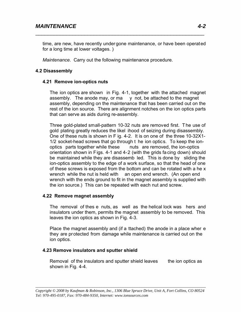
The ion optics are shown in Fig. 4-1, together with the attached magnet assembly. The anode may, or ma y not, be attached to the magnet assembly, depending on the maintenance that has been carried out on the rest of the ion source. There are alignment notches on the ion optics parts that can serve as aids during re-assembly.
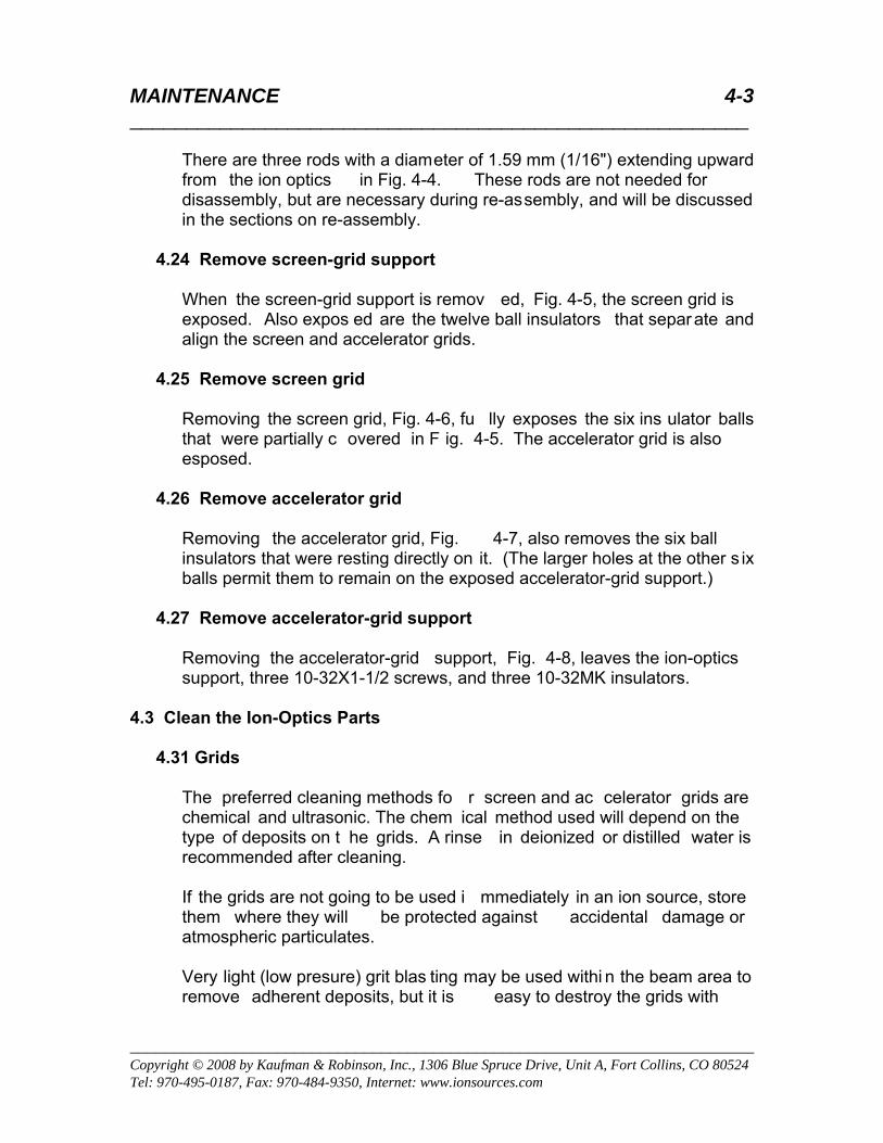
Three gold-plated small-pattern 10-32 nuts are removed first. The use of
gold plating greatly reduces the likel ihood of seizing during disassembly. One of these nuts is shown in F ig. 4-2. It is on one of the three 10-32X1-1/2 socket-head screws that go through t he ion optics. To keep the ion-optics parts together while these nuts are removed, the ion-optics orientation shown in Figs. 4-1 and 4-2 (with the grids fa cing down) should be maintained while they are disassemb led. This is done by sliding the ion-optics assembly to the edge of a work surface, so that the head of one of these screws is exposed from the bottom and can be rotated with a he x wrench while the nut is held with an open end wrench. (An open end wrench with the ends ground to fit in the magnet assembly is supplied with the ion source.) This can be repeated with each nut and screw.
4.22 Remove magnet assembly
The removal of thes e nuts, as well as the helical lock was hers and insulators under them, permits the magnet assembly to be removed. This leaves the ion optics as shown in Fig. 4-3.
Place the magnet assembly and (if a ttached) the anode in a place wher e they are protected from damage while maintenance is carried out on the ion optics.
4.23 Remove insulators and sputter shield
Removal of the insulators and sputter shield leaves the ion optics as shown in Fig. 4-4.
MAINTENANCE 4-3 _______________________________________________________
________________________________________________________________________ Copyright © 2008 by Kaufman & Robinson, Inc., 1306 Blue Spruce Drive, Unit A, Fort Collins, CO 80524 Tel: 970-495-0187, Fax: 970-484-9350, Internet: www.ionsources.com
There are three rods with a diameter of 1.59 mm (1/16") extending upward from the ion optics in Fig. 4-4. These rods are not needed for disassembly, but are necessary during re-assembly, and will be discussed in the sections on re-assembly.
4.24 Remove screen-grid support
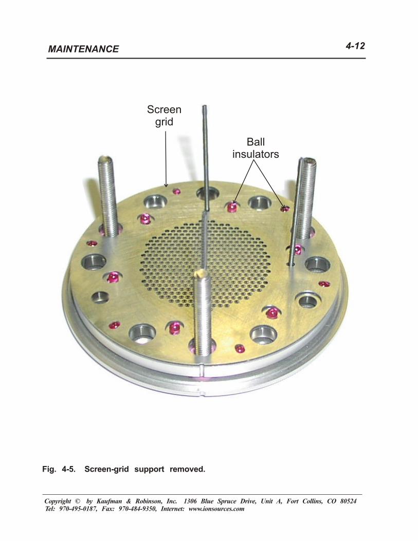
When the screen-grid support is remov ed, Fig. 4-5, the screen grid is exposed. Also expos ed are the twelve ball insulators that separate and align the screen and accelerator grids.
4.25 Remove screen grid
Removing the screen grid, Fig. 4-6, fu lly exposes the six ins ulator balls that were partially c overed in F ig. 4-5. The accelerator grid is also esposed.
4.26 Remove accelerator grid
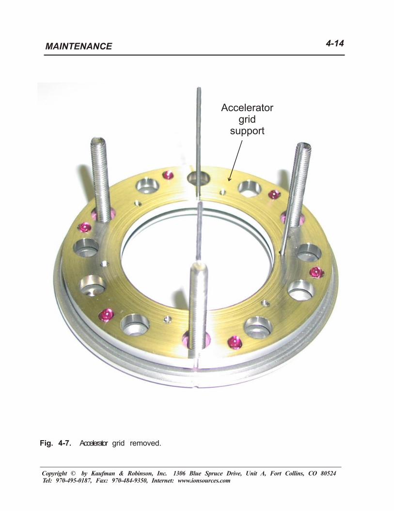
Removing the accelerator grid, Fig. 4-7, also removes the six ball insulators that were resting directly on it. (The larger holes at the other s ix balls permit them to remain on the exposed accelerator-grid support.)
4.27 Remove accelerator-grid support
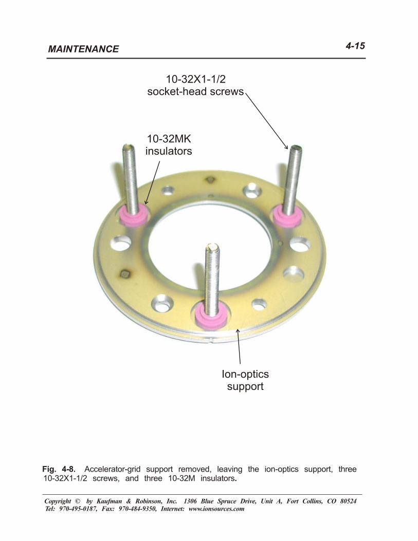
Removing the accelerator-grid support, Fig. 4-8, leaves the ion-optics support, three 10-32X1-1/2 screws, and three 10-32MK insulators.
4.3 Clean the Ion-Optics Parts
4.31 Grids
The preferred cleaning methods fo r screen and ac celerator grids are chemical and ultrasonic. The chem ical method used will depend on the type of deposits on t he grids. A rinse in deionized or distilled water is recommended after cleaning.
If the grids are not going to be used i mmediately in an ion source, store them where they will be protected against accidental damage or atmospheric particulates.
Very light (low presure) grit blas ting may be used withi n the beam area to remove adherent deposits, but it is easy to destroy the grids with

MAINTENANCE 4-4 _______________________________________________________
________________________________________________________________________ Copyright © 2008 by Kaufman & Robinson, Inc., 1306 Blue Spruce Drive, Unit A, Fort Collins, CO 80524 Tel: 970-495-0187, Fax: 970-484-9350, Internet: www.ionsources.com
excessive pressure. For the areas of the grids in c ontacts with their supports, no cleaning should be nece ssary. Further, any roughening of these areas can adv ersely affect the sliding motions due to thermal expansion and contraction that must take place between the gr ids and their supports.
4.32 Grid supports
For the areas of the screen-grid and a ccelerator-grid supports in contacts with the gr ids, no cleaning s hould be necessary. There are the same concerns about roughening t hese surfaces as t here are about the matching surfaces on the grids. As long as these ar eas are protected from damage while the re st of the supports are cleaned, there should be no restriction on the type of cleaning used on the rest of the supports.
4.33 Ion-optics support
There is no restriction on the t ype of cleaning used on this part. If preferred, the exterior surface of th is support, where most of the depos its will occur, can be cleaned with conventional grit blasting.
4.4 Selection of Focusing or Divergent Configuration
The arrangement of parts in Sec tion 4.2 correspond to the diver gent-beam configuration of the Microdished™ molybdenum optics. A simple way to check which configuration is being used is to look at the three rods in Figs. 4-4 through 4-8. When the i on optics are oriented with the alignme nt notches facing you, the divergent-beam configur ation will hav e rods at 12:00, 3:00, and 6:00 o’clock. The focused-beam c onfiguration will have rods at 12:00, 6:00, and 9:00 o’clock.
4.5 Re-assembly of the Ion Optics
The re-assembly of the ion optics is generally the reverse of the disassembly, but a more detailed description is nec essary to avoid problem s. Several things should be kept in mind.
a. Use new insulators.
b. Keep the alignment notches in the same circumferential location.
c. Do not re-use helical stainles s-steel lock washers. They can become compressed from use and their cost is negligible.
MAINTENANCE 4-5 _______________________________________________________
________________________________________________________________________ Copyright © 2008 by Kaufman & Robinson, Inc., 1306 Blue Spruce Drive, Unit A, Fort Collins, CO 80524 Tel: 970-495-0187, Fax: 970-484-9350, Internet: www.ionsources.com
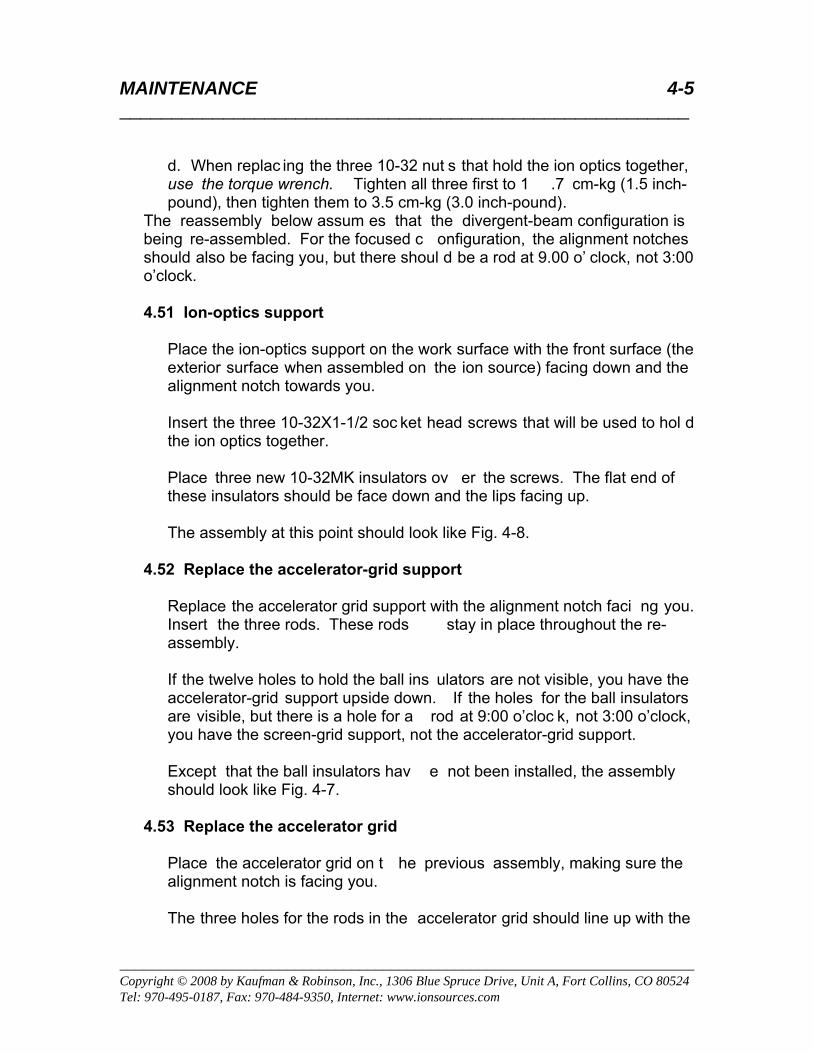
d. When replac ing the three 10-32 nut s that hold the ion optics together, use the torque wrench. Tighten all three first to 1 .7 cm-kg (1.5 inch-pound), then tighten them to 3.5 cm-kg (3.0 inch-pound).
The reassembly below assum es that the divergent-beam configuration is being re-assembled. For the focused c onfiguration, the alignment notches should also be facing you, but there shoul d be a rod at 9.00 o’ clock, not 3:00 o’clock.
4.51 Ion-optics support
Place the ion-optics support on the work surface with the front surface (the exterior surface when assembled on the ion source) facing down and the alignment notch towards you.
Insert the three 10-32X1-1/2 soc ket head screws that will be used to hol d the ion optics together.
Place three new 10-32MK insulators ov er the screws. The flat end of these insulators should be face down and the lips facing up.
The assembly at this point should look like Fig. 4-8.
4.52 Replace the accelerator-grid support
Replace the accelerator grid support with the alignment notch faci ng you. Insert the three rods. These rods stay in place throughout the re-assembly.
If the twelve holes to hold the ball ins ulators are not visible, you have the accelerator-grid support upside down. If the holes for the ball insulators are visible, but there is a hole for a rod at 9:00 o’cloc k, not 3:00 o’clock, you have the screen-grid support, not the accelerator-grid support.
Except that the ball insulators hav e not been installed, the assembly should look like Fig. 4-7.
4.53 Replace the accelerator grid
Place the accelerator grid on t he previous assembly, making sure the alignment notch is facing you.
The three holes for the rods in the accelerator grid should line up with the

MAINTENANCE 4-6 _______________________________________________________
________________________________________________________________________ Copyright © 2008 by Kaufman & Robinson, Inc., 1306 Blue Spruce Drive, Unit A, Fort Collins, CO 80524 Tel: 970-495-0187, Fax: 970-484-9350, Internet: www.ionsources.com
three holes in the accelerator-grid support, as shown in Fig. 4-6, for you to replace the accelerator grid. If there is a hole at 9:00 o’c lock, not 3:00 o’clock, the grid may be upside down.
If you have the alignment notch facing you and the three holes for the rods line up, the six large holes for ball insu lators in the accelerator grid should line up with the six recessed holes in t he accelerator-grid support, so that ball insulators can be dropped into these recesses.
(For the divergent-beam configuration, the recess ed holes in the accelerator-grid support are near its outer diameter. For the focused-beam configuration, they are near its inner diameter.)
4.54 Install new ball insulators
Install twelve new ball insulators. Six should rest on top of the accelerator grid and six should be in the larger holes of the accelerator grid and rest on the accelerator-grid support, as shown in Fig. 4-6.
4.55 Replace the screen grid
If the alignment notch is facing y ou and the three holes in the scr een grid fit over the rods, the screen grid is in stalled correctly. At this point the assembly should look like Fig. 4-5.
If the alignment notch is facing you, but there is a hole for a rod at 9:00 o’clock instead of 3:00 o’clock, the screen grid is upside down.
4.56 Replace the screen-grid support
The assembly should now appear as shown in Fig. 4-4.
4.57 Replace sputter shield and 10-32M insulators
Install the sputter shield with the alignm ent notch facing you. (If it doesn’t face you, you won’t be able to install it over the three rods.)
Install three new 10-32M insulators over the three screws. The lips of the insulators should ext end through the s putter shield into the screen-grid support.
The assembly should now look like Fig. 4-3, except that the three rods are still in place.
MAINTENANCE 4-7 _______________________________________________________
________________________________________________________________________ Copyright © 2008 by Kaufman & Robinson, Inc., 1306 Blue Spruce Drive, Unit A, Fort Collins, CO 80524 Tel: 970-495-0187, Fax: 970-484-9350, Internet: www.ionsources.com
4.58 Replace magnet assembly
The magnet assembly is placed ov er the ion-optics assembly with the three rods still in p lace. To av oid interference with th e rods, the anode should be removed from the magnet a ssembly before the two assemblies are brought together.
Place three new 10-32M insulators over the three screws in the ion optics . The lips of these insulators should ext end down into the front ring of the magnet assembly. Place the new 10- 32 split was hers on top of the insulators. Remove the rod nearest the alignment mark. Leave the other two rods in place.
Install and finger-tighten the three gold-plated 10-32 nuts on the three ion-optics screws.
The two rods can now be removed. They served to keep the parts in approximate alignment unt il tightening of the screw s can bring the parts into final precise alignment.
The assembly should now look like Fig. 4-2.
4.59 Tighten ion-optics screws
Use the torque wrench to tighten all thr ee screws - failure to use a torque wrench can damage the ion opt ics. Place the assembly sideways on a workbench or other hard surface. Hold th e nuts with a 3/8 “wrench and tighten all three screws first to 1.7 c m-kg (1.5 inch-pound) with the torque wrench, then tighten them to 3.5 cm-kg (3.0 inch-pound).
You can now replace the anode, holding it in place with a 10-32 nut on the anode connection rod, as shown in Fig. 4-1.
The combined ion-optics/magnet/anode assembly is now ready to install in the ion source as described in Secti on 5.29 of the manual for the KDC 40 Ion Source, to which this manual is a supplement

MAINTENANCE 4-8 _______________________________________________________
________________________________________________________________________ Copyright © 2008 by Kaufman & Robinson, Inc., 1306 Blue Spruce Drive, Unit A, Fort Collins, CO 80524 Tel: 970-495-0187, Fax: 970-484-9350, Internet: www.ionsources.com
4.6 Spares
Kits of spares are available from KRI®.
Ion-optics maintenance kit: Twelve ball insulators Three 10-32MK insulators Six 10-32M insulators Three helical 10-32 lock washers
MAINTENANCE 4-8
Fig. 4-1. Microdished™ molybdenum ion optics removed from the KDC 40 IonSource. The ion optics are shown at the right, with the magnet assembly andanode attached.
Copyright © by Kaufman & Robinson, Inc. 1306 Blue Spruce Drive, Unit A, Fort Collins, CO 80524Tel: 970-495-0187, Fax: 970-484-9350, Internet: www.ionsources.com
Magnetassembly
Anodeconnection
rod
Anode
Ionoptics
Outershell
MAINTENANCE 4-9
Fig. 4-2. Close-up view of one of three nuts that must be removed todisassemble the ion optics.
Copyright © by Kaufman & Robinson, Inc. 1306 Blue Spruce Drive, Unit A, Fort Collins, CO 80524Tel: 970-495-0187, Fax: 970-484-9350, Internet: www.ionsources.com
Gold-plated10-32 nut
MAINTENANCE 4-10
Fig. 4-3. Ion optics after three 10-32 nuts have been removed and the magnetassembly has been lifted off.
Copyright © by Kaufman & Robinson, Inc. 1306 Blue Spruce Drive, Unit A, Fort Collins, CO 80524Tel: 970-495-0187, Fax: 970-484-9350, Internet: www.ionsources.com
10-32Minsulator
Sputtershield
10-32 x 1-1/2”socket-head
screws
MAINTENANCE 4-11
Fig. 4-4. Insulators and sputter shield removed. The three rods shown standingupright in the ion optics will not be present during disassembly, but are used inre-assembly.
Copyright © by Kaufman & Robinson, Inc. 1306 Blue Spruce Drive, Unit A, Fort Collins, CO 80524Tel: 970-495-0187, Fax: 970-484-9350, Internet: www.ionsources.com
Screen-gridsupport
Rods usedduring
re-assembly
MAINTENANCE 4-12
Fig. 4-5. Screen-grid support removed.
Copyright © by Kaufman & Robinson, Inc. 1306 Blue Spruce Drive, Unit A, Fort Collins, CO 80524Tel: 970-495-0187, Fax: 970-484-9350, Internet: www.ionsources.com
Screengrid
Ballinsulators

MAINTENANCE 4-13
Fig. 4-6. Screen grid removed.
Copyright © by Kaufman & Robinson, Inc. 1306 Blue Spruce Drive, Unit A, Fort Collins, CO 80524Tel: 970-495-0187, Fax: 970-484-9350, Internet: www.ionsources.com
Acceleratorgrid
Ballinsulators
MAINTENANCE 4-14
Fig. 4-7. grid removed.Accelerator
Copyright © by Kaufman & Robinson, Inc. 1306 Blue Spruce Drive, Unit A, Fort Collins, CO 80524Tel: 970-495-0187, Fax: 970-484-9350, Internet: www.ionsources.com
Acceleratorgrid
support
MAINTENANCE 4-15
Fig. 4-8. Accelerator-grid support removed, leaving the ion-optics support, three10-32X1-1/2 screws, and three 10-32M insulators.
Copyright © by Kaufman & Robinson, Inc. 1306 Blue Spruce Drive, Unit A, Fort Collins, CO 80524Tel: 970-495-0187, Fax: 970-484-9350, Internet: www.ionsources.com
10-32MKinsulators
Ion-opticssupport
10-32X1-1/2socket-head screws
WARRANTY 5-1 _______________________________________________________
________________________________________________________________ Copyright © 2008 by Kaufman & Robinson, Inc., 1306 Blue Spruce Drive, Unit A, Fort Collins, CO 80524 Tel: 970-495-0187, Fax: 970-484-9350, Internet: www.ionsources.com
5 WARRANTY The Kaufman & Robinson, Inc., (KRI ®) KDC 40 Ion Source is warranted for one year against manufacturer defects in materi als or workmanship. This year starts with the date of shipment to the end user, provided in the event of OEM purchase that date of shipment is not later than three months a fter the original shipment from KRI®, Inc., and also prov ided the equipment has been operated and maintained according to the pr ocedures described herein. KRI ® will service and at its option repair or replace def ective parts, free of charge during the one-year warranty period, at the KRI ® facility. This warranty ex cludes failures or defects resulting from misuse or unauthorized m odification. This warranty does not cover expendable parts, which are as follows: Cathode and neutralizer filaments Ion-optics grids Ball/alumina insulators Gas-line isolator This warranty supersedes all other warr anties expressed or implied. KRI ® assumes no liab ility for damages or los s of production. Re port defects or problems to KRI® immediately. For return of equipment for repair, contact KRI ® to arrange for a return materials authorizat ion (RMA) number prior to shipment of the equipment to KRI® facilities. For service or repair, contact KRI®: Kaufmen & Robinson, Inc. 1306 Blue Spruce Dr., Unit A Fort Collins, CO 80524 (970) 495-0187 (970) 484-9350 (FAX) Please include the following information relating to the defect and the item to be returned: Product Serial number Detailed description of problem Date of purchase Name of company with address and contact person


![KDC-X303 KDC-BT33 KDC-MP375BT KDC-BT375U KDC-BT275U …manual.kenwood.com/files/B5K-0553-10.pdf · 2021. 3. 17. · KDC-BT33 KDC-BT275U KDC-BT23 B5K-0553-10 [KN] KDC-X303 KDC-BT375U](https://static.fdocuments.us/doc/165x107/611b813b01043c189008dd69/kdc-x303-kdc-bt33-kdc-mp375bt-kdc-bt375u-kdc-bt275u-2021-3-17-kdc-bt33-kdc-bt275u.jpg)


