KCC Co., Ltd. PNEUMATIC & HYDRAULIC KP70/140H … · KCC Co., Ltd. 2-8 PNEUMATIC & HYDRAULIC...
21
KCC Co., Ltd. www.kccpr.com 8 2 - PNEUMATIC & HYDRAULIC KP70/140H series Standard Hydraulic Cylinder KP70H - FA 80 C - N 100 A B ᐭ ᐮ ᐯ ᐰ ᐱ ᐲ ᐳ ᐴ ᐵ ᐶ ᐷ ᐸ ᐹ ᐺ How to Order KP70/140H series ᐵ Port position A Standard B,C,D 5HIHU WR WKH QH[W ソJXUH ᐶ Cushion valve position B Standard A,C,D 5HIHU WR WKH QH[W ソJXUH ఐ Flange type tube is applied for stroke over 800mm at Ϩ140 ~ Ϩ160. ᐷ Bellows Material Max. ambient temperature Nil Without bellows J Nylon Tarpaulin 60ఁ K Neoprene Cloth 110ఁ ᐺ Number of auto switch Nil 2 pcs 1 1 pc N N pcs (N:3,4,5...) ఐ Only for single rod auto switch attached type. ᐹ Auto switch Reed A/S Model Solid state A/S Model A54 D-A54K F59 D-F59K A56 D-A56K F5P D-F5PK A64 D-A64K J59 D-J59K A90(V) D-A90(V)K J51 D-J51K A93(V) D-A93(V)K F9N D-F9N(V)K A96(V) D-A96(V)K F9P D-F9P(V)K F9B D-F9B(V)K ఐ Only for single rod auto switch attached type. ఐ For more information, refer to Auto Switch Catalogue. Symbol Double Acting / Single Rod Double Acting / Double Rod ᐯ Seal Material Nil Nitrile Urethane(Standard) 1 Nitrile rubber 2 Urethane rubber 3 Fluoric rubber ఐ The packing material of the compact seal is nitrile rubber. ᐮ Compact seal Nil Without seal (Standard) C With compact seal ᐭ Series KP70H Single rod 70kgf/cm 2 KP140H 140kgf/cm 2 KP70H W Double rod 70kgf/cm 2 KP140H W 140kgf/cm 2 KP70HL With auto switch (Single rod) 70kgf/cm 2 KP140HL 140kgf/cm 2 KP70HL W With auto switch (Double rod) 70kgf/cm 2 KP140HL W 140kgf/cm 2 ఐ For 140kgf/cm 2 series, B type rod is recommended. ᐱ Bore size ᐲ Rod type Bore size B C (Heavy Duty) (Standard) 40 Ϩ40 Ϩ22 Ϩ18 50 Ϩ50 Ϩ28 Ϩ22 63 Ϩ63 Ϩ35 Ϩ28 80 Ϩ80 Ϩ45 Ϩ35 100 Ϩ100 Ϩ55 Ϩ45 125 Ϩ125 Ϩ70 Ϩ55 140 Ϩ140 Ϩ80 Ϩ65 150 Ϩ150 Ϩ85 Ϩ65 160 Ϩ160 Ϩ90 Ϩ70 180 Ϩ180 Ϩ100 Ϩ80 200 Ϩ200 Ϩ112 Ϩ90 250 Ϩ250 Ϩ140 Ϩ112 ᐳ Cushion N Without cushion B Cushions on both ends R Cushion on the rod side H Cushion on the head side ᐰ Mounting style SD Standard FC Rod side square タDQJH LA Axial angle of foot FD Head side VTXDUH タDQJH LB Axial foot CA Single clevis FA Rod side rectangular タDQJH CB Double clevis FB Head side rectangular タDQJH TC Center trunnion FY Rod side rectangular タDQJH TA Rod side trunnion FZ Head side rectangular タDQJH ఐ Pressure for LB, FA, FB type is 70kgf/cm 2 . ᐴ Cylinder stroke Bore size Max. stroke Ϩ40,Ϩ50 1200 Ϩ63, Ϩ80 1600 Ϩ100 2000 Ϩ125~Ϩ250 2000 ఐ Check buckling, as it varies depending on mounting style. ఐ Contact us for longer stroke. Features Ɣ Standard tie rod type hydraulic cylinder Ɣ Double acting hydraulic cylinder for 70 kgf/cm 2 or 140kgf/cm 2 with bore sizes from Ϩ40 to Ϩ250. Ɣ High performance cushion to reduce shock when stopping. Ɣ Various mounting styles (SD, LA, LB, FA, FB, FY, FZ, FC, FD, CA, CB, TC, TA) ᐸ Rod end attachment Nil Rod end nut (Standard) I Single knuckle joint Y Double knuckle joint KP70H-FA80C-N100 A B KP140HL-FY40B-N100 A B A54 For more info visit us : http://www.nabelsakha.com
Transcript of KCC Co., Ltd. PNEUMATIC & HYDRAULIC KP70/140H … · KCC Co., Ltd. 2-8 PNEUMATIC & HYDRAULIC...

KCC Co., Ltd.
www.kccpr.com 82 -
PNEUMATIC & HYDRAULIC
KP70/140H seriesStandard Hydraulic Cylinder
KP70H - FA 80 C - N 100 A B
How to Order
KP70/140H series
Port positionA Standard
B,C,D
Cushion valve positionB Standard
A,C,D Flange type tube is applied for stroke over 800mm at 140 ~ 160.
Bellows
Material Max. ambient temperature
Nil Without bellowsJ Nylon Tarpaulin 60K Neoprene Cloth 110
Number of auto switchNil 2 pcs1 1 pcN N pcs (N:3,4,5...)
Only for single rod auto switch attached type.
Auto switch
Reed A/S Model Solid state A/S Model
A54 D-A54K F59 D-F59KA56 D-A56K F5P D-F5PKA64 D-A64K J59 D-J59K
A90(V) D-A90(V)K J51 D-J51KA93(V) D-A93(V)K F9N D-F9N(V)KA96(V) D-A96(V)K F9P D-F9P(V)K
F9B D-F9B(V)K Only for single rod auto switch attached type. For more information, refer to Auto Switch
Catalogue.
Symbol
Double Acting /Single Rod
Double Acting / Double Rod
Seal MaterialNil Nitrile Urethane(Standard)1 Nitrile rubber2 Urethane rubber3 Fluoric rubber
The packing material of the compact seal is nitrile rubber.
Compact sealNil Without seal (Standard)C With compact seal
SeriesKP70H
Single rod70kgf/cm2
KP140H 140kgf/cm2
KP70H WDouble rod
70kgf/cm2
KP140H W 140kgf/cm2
KP70HL With auto switch(Single rod)
70kgf/cm2
KP140HL 140kgf/cm2
KP70HL W With auto switch(Double rod)
70kgf/cm2
KP140HL W 140kgf/cm2
For 140kgf/cm2 series, B type rod is recommended.
Bore size Rod type
Bore sizeB C
(Heavy Duty) (Standard)
40 40 22 1850 50 28 2263 63 35 2880 80 45 35
100 100 55 45125 125 70 55140 140 80 65150 150 85 65160 160 90 70180 180 100 80200 200 112 90250 250 140 112
CushionN Without cushionB Cushions on both endsR Cushion on the rod sideH Cushion on the head side
Mounting style
SD Standard FC Rod side square
LA Axial angle of foot FD Head side
LB Axial foot CA Single clevis
FARod side
rectangular CB Double clevis
FBHead side rectangular TC Center trunnion
FYRod side
rectangular TA Rod side trunnion
FZHead side rectangular
Pressure for LB, FA, FB type is 70kgf/cm2.
Cylinder strokeBore size Max. stroke
40, 50 120063, 80 1600
100 2000125~ 250 2000
Check buckling, as it varies depending on mounting style.
Contact us for longer stroke.
Features
Standard tie rod type hydraulic cylinder
Double acting hydraulic cylinder for 70 kgf/cm2
or 140kgf/cm2 with bore sizes from 40 to 250.
High performance cushion to reduce shock
when stopping.
Various mounting styles
( SD, LA, LB, FA, FB, FY, FZ, FC, FD, CA, CB, TC, TA)
Rod end attachmentNil Rod end nut (Standard)I Single knuckle jointY Double knuckle joint
KP70H-FA80C-N100 A B
KP140HL-FY40B-N100 A B A54
For more info visit us : http://www.nabelsakha.com

KCC Co., Ltd.
www.kccpr.com 92 -
PNEUMATIC & HYDRAULIC
Hydraulic Cylinder
Reference Data
KP70/140H
KP210H
KPC70/140H
KPC210H
KTC70HP
KP140HS
KP125/160A
KP35R
KH
KP70/140H seriesStandard Hydraulic Cylinder
Cushion LengthUnit:mm
Bore size 40 ~ 63 80 ~ 100 125 ~ 150 160 180 200 250Cushion length 22 25 30 35 40 45 50
Bore sizeMounting
40 50 63 80 100 125 140 150 160 180 200 250
Axial angle of foot LA(Hyd.)40 LA(Hyd.)50 LA(Hyd.)63 LA(Hyd.)80 LA(Hyd.)100 LA(Hyd.)125 LA(Hyd.)140 LA(Hyd.)150 LA(Hyd.)160 LA(Hyd.)180 LA(Hyd.)200 LA(Hyd.)250
Axial foot LB(Hyd.)40 LB(Hyd.)50 LB(Hyd.)63 LB(Hyd.)80 LB(Hyd.)100
LB(Hyd.)125LB(Hyd.)140 LB(Hyd.)150 LB(Hyd.)160 LB(Hyd.)180 LB(Hyd.)200 LB(Hyd.)250
Flange FA/FB (Hyd.)40
FA/FB(Hyd.)50
FA/FB(Hyd.)63
FA/FB(Hyd.)80
FA/FB(Hyd.)100
FA/FB(Hyd.)125
FA/FB(Hyd.)140
FA/FB(Hyd.)150
FA/FB(Hyd.)160
FA/FB(Hyd.)180
FA/FB(Hyd.)200
FA/FB(Hyd.)250
Reinforced FY/FZ(Hyd.)40
FY/FZ(Hyd.)50
FY/FZ(Hyd.)63
FY/FZ(Hyd.)80
FY/FZ(Hyd.)100
FY/FZ(Hyd.)125
FY/FZ(Hyd.)140
FY/FZ(Hyd.)150
FY/FZ(Hyd.)160
FY/FZ(Hyd.)180
FY/FZ(Hyd.)200
FY/FZ(Hyd.)250
FC/FD(Hyd.)40
FC/FD(Hyd.)50
FC/FD(Hyd.)63
FC/FD(Hyd.)80
FC/FD(Hyd.)100
FC/FD(Hyd.)125
FC/FD(Hyd.)140
FC/FD(Hyd.)150
FC/FD(Hyd.)160
FC/FD(Hyd.)180
FC/FD(Hyd.)200
FC/FD(Hyd.)250
Single clevis CA(Hyd.)40 CA(Hyd.)50 CA(Hyd.)63 CA(Hyd.)80CA(Hyd.)
100CA(Hyd.)
125CA(Hyd.)
140CA(Hyd.)
150CA(Hyd.)
160CA(Hyd.)
180CA(Hyd.)
200CA(Hyd.)
250
Double clevis CB(Hyd.)40 CB(Hyd.)50 CB(Hyd.)63 CB(Hyd.)80 CB(Hyd.)100 CB(Hyd.)125 CB(Hyd.)140 CB(Hyd.)150 CB(Hyd.)160 CB(Hyd.)180 CB(Hyd.)200 CB(Hyd.)250
Trunnion TA/TC(Hyd.)40
TA/TC(Hyd.)50
TA/TC(Hyd.)63
TA/TC(Hyd.)80
TA/TC(Hyd.)100
TA/TC(Hyd.)125
TA/TC(Hyd.)140
TA/TC(Hyd.)150
TA/TC(Hyd.)160
TA/TC(Hyd.)180
TA/TC(Hyd.)200
TA/TC(Hyd.)250
Double clevis pin
CB PIN (Hyd.)40
CB PIN (Hyd.)50
CB PIN (Hyd.)63
CB PIN (Hyd.)80
CB PIN (Hyd.)100
CB PIN (Hyd.)125
CB PIN (Hyd.)140
CB PIN (Hyd.)150
CB PIN (Hyd.)160
CB PIN (Hyd.)180
CB PIN (Hyd.)200
CB PIN (Hyd.)250
Mounting Style
TypeStandard Auto switch attached
KP70H KP140H KP70HL KP140HL
Bore size 40, 50, 63, 80, 100, 125, 140, 150,160, 180, 200, 250 40, 50, 63, 80, 100
Operating pressure 70kgf/cm2 (7.0MPa) 140kgf/cm2 (14.0MPa) 70kgf/cm2 (7.0MPa) 140kgf/cm2 (14.0MPa)
Max. operating pressureHead side:90kgf/cm2 (9.0MPa)Rod side:(B)135kgf/cm2 (13.5MPa) (C)110kgf/cm2 (11.0MPa)
Head side:180kgf/cm2 (18.0MPa)Rod side:(B)180kgf/cm2 (18.0MPa) (C)140kgf/cm2 14.0MPa)
Head side:90kgf/cm2 (9.0MPa)Rod side:(B)135kgf/cm2 (13.5MPa) (C)110kgf/cm2 (11.0MPa)
Head side:180kgf/cm2 (18.0MPa)Rod side:(B)180kgf/cm2 (18.0MPa) (C)140kgf/cm2 (14.0MPa)
Proof pressure 105kgf/cm2 (10.5MPa) 210kgf/cm2 (21.0MPa) 105kgf/cm2 (10.5MPa) 210kgf/cm2 (21.0MPa)
Min. operating pressure cm2(0.3MPa), cm2 cm2(0.4MPa)
Operating piston speed40 ~ 63 : 8~400mm/sec80 ~ 125 : 8~300mm/sec
140 ~ 250 : 8~200mm/sec
40 ~ 63 : 8~400mm/sec80 ~ 100 : 8~300mm/sec
-10 ~ 80 -10 ~ 70Cushion Metal fitting type
Working oil Petroleum-based fluidTolerance of thread KS class 2
Tolerance of stroke
Tube material Carbon steel for machine structural use Stainless steelMounting style SD, LA, (LB), (FA), (FB), FY, FZ, FC, FD, CA, CB, TC, TA
Operating pressure: Max. allowable setting pressure for a relief valve while cylinder is operating. Max. operating pressure: Maximum allowable pressure generated in a cylinder (surge pressure, etc.). Proof pressure: Test pressure for a cylinder can withstand without unreliable performance when returning to operating pressure. Min. operating pressure: Minimum pressure for cylinder installed horizontally and operating without load. Operating pressure for the mounting styles in ( ) are 70kgf/cm2. A longer thread length (A) is required when lock nut is applied on the end of the piston rod.
+0.80
+1.40
+1.00
+1.60
+1.250
+1.80
For more info visit us : http://www.nabelsakha.com

KCC Co., Ltd.
www.kccpr.com 102 -
PNEUMATIC & HYDRAULIC
Bore sizeAccessory 40 50 63 80 100 125 140 150 160
Single knuckle
joint
B I(Hyd.)40B I(Hyd.)50B I(Hyd.)63B I(Hyd.)80B I(Hyd.)100B I(Hyd.)125B I(Hyd.)140B I(Hyd.)150B I(Hyd.)160B
C I(Hyd.)40C I(Hyd.)50C I(Hyd.)63C I(Hyd.)80C I(Hyd.)100C I(Hyd.)125C I(Hyd.)140C I(Hyd.)150C I(Hyd.)160C
Double knuckle
joint
B Y(Hyd.)40B Y(Hyd.)50B Y(Hyd.)63B Y(Hyd.)80B Y(Hyd.)100B Y(Hyd.)125B Y(Hyd.)140B Y(Hyd.)150B Y(Hyd.)160B
C Y(Hyd.)40C Y(Hyd.)50C Y(Hyd.)63C Y(Hyd.)80C Y(Hyd.)100C Y(Hyd.)125C Y(Hyd.)140C Y(Hyd.)150C Y(Hyd.)160C
Double knucklejoint pin
Y PIN(Hyd.)40
Y PIN(Hyd.)50
Y PIN(Hyd.)63
Y PIN(Hyd.)80
Y PIN(Hyd.)100
Y PIN(Hyd.)125
Y PIN(Hyd.)140
Y PIN(Hyd.)150
Y PIN(Hyd.)160
Rod end nut RN(Hyd.)40 RN(Hyd.)50 RN(Hyd.)63 RN(Hyd.)80 RN(Hyd.)100 RN(Hyd.)125 RN(Hyd.)140 RN(Hyd.)150 RN(Hyd.)160
Rod End Attachment
KP70/140H seriesStandard Hydraulic Cylinder
MassUnit : kg
Bore size Rod type
Basic mass (SD) Mounting mass Accessory massAdditional mass for each 1mm of
strokeStandard
typeDouble rod type LA LB FA FB FC FD FY FZ CA CB TA TC Single
knuckle jointDouble
knuckle jointStandard
typeDouble rod type
40B 3.5 4.4
0.5 0.5 0.2 0.7 0.7 1.1 0.3 0.8 0.5 0.6 0.1 0.6 0.5 0.70.011 0.014
C 3.4 4.3 0.010 0.012
50B 5.0 6.4
0.9 0.7 0.7 1.2 1.5 2.0 1.1 1.6 1.0 1.2 0.4 1.0 1.0 1.20.014 0.019
C 4.9 6.2 0.012 0.014
63B 7.9 10.2
1.0 1.2 1.0 1.8 2.2 3.1 1.6 2.4 2.0 2.6 0.6 1.2 2.7 3.90.019 0.027
C 7.6 9.8 0.017 0.022
80B 16.2 20.3
1.8 2.0 1.1 3.0 2.8 4.7 2.1 4.0 3.0 3.6 0.6 2.1 2.7 3.70.032 0.045
C 15.5 19.4 0.027 0.035
100B 26.0 32.7
2.1 2.9 1.8 4.8 4.6 7.4 3.9 6.9 5.5 6.7 1.0 3.8 4.2 7.70.048 0.067
C 24.9 31.1 0.042 0.055
125B 42.9 53.6
3.2 5.5 2.9 8.4 8.0 13.0 6.2 12.1 9.9 12.1 2.1 6.2 8.0 14.60.077 0.107
C 42.5 52.7 0.065 0.084
140B 59.6 73.9
3.8 7.7 3.2 11.1 9.2 17.1 8.2 16.1 16.7 21.0 4.1 11.1 19.0 28.80.100 0.140
C 56.0 69.6 0.085 0.111
150B 66.9 86.5
4.8 9.6 4.9 13.7 16.6 22.4 10.7 19.5 18.2 26.8 4.6 10.9 18.9 28.30.118 0.162
C 67.9 83.6 0.101 0.127
160B 84.3 114.6
5.4 10.0 5.3 16.5 19.0 25.2 11.3 22.5 22.9 28.4 5.2 14.8 22.7 34.20.121 0.171
C 79.9 99.1 0.102 0.132
180B 115.1 -
7.9 13.8 7.7 22.7 25.0 33.6 17.5 32.5 33.8 42.9 - 19.4 - -0.179 0.241
C 108.5 - 0.157 0.197
200B 155.2 -
11.4 21.0 10.6 31.6 28.8 48.7 22.6 43.6 51.4 65.4 - 27.2 - -0.220 0.295
C 147.3 - 0.192 0.242
250B 283.7 -
18.3 46.7 17.5 55.1 48.2 88.3 42.5 80.1 74.5 91.6 - 43.3 - -0.333 0.454
C 264.1 - 0.290 0.365
Ex.) KP140H-LA80B-N200 A B Basic mass: 16.2 / Additional mass: 0.032 / Cylinder stroke: 200mm / LA type:1.8 16.2+(0.032 X 200) + 1.8 = 24.4kg
Calculation:
For more info visit us : http://www.nabelsakha.com

KCC Co., Ltd.
www.kccpr.com 112 -
PNEUMATIC & HYDRAULIC
Hydraulic Cylinder
Reference Data
KP70/140H
KP210H
KPC70/140H
KPC210H
KTC70HP
KP140HS
KP125/160A
KP35R
KH
KP70/140H seriesStandard Hydraulic Cylinder
Structure- 40C~ 63C
Packing List
21 22 23 2417 18 19 20 251012 13 14
15 16
11
Part no. Parts 40 (C) 50 (C) 63 (C) 40 (B) 50 (B) Material Quantity
17 Dust Seal 18×26×7 22×30.6×6.5 28×36.6×6.5 22×30.6×6.5 28×36.6×6.5 Urethane 1
18 Rod Packing 18×26×5.5 22×30×5.5 28×36×8 22×30×5.5 28×36×8 Urethane 1
19 O-Ring G-30 G-35 G-45 G-30 G-35 NBR 1
20 DU Bush 1820 2220 2820 2220 2820 - 1
21 O-Ring AN-111 AN-114 AN-117 AN-111 AN-114 NBR 1
22 Wear Ring 40×35×10 50×45×15 60×53×20 40×35×10 50×45×15 Phenol 1
23 Piston Packing 40×30×6 50×40×6 63×53×6 40×30×6 50×40×6 Urethane 2
24 O-Ring - - G-58 - - NBR 2
25 O-Ring G-40 G-50 G-63 G-40 G-50 NBR 2
Part List
Part no. Parts Material Quantity
1 Cylinder Tube STKM13C 1
2 Rod Cover SS400 1
3 Head Cover SS400 1
4 Piston SM45C 1
5 Piston Rod SM45C 1
6 Bush SM45C 1
7 Retainer (Bush Cover) SS400 1
8 Spring Washer SWRH57B 8
Part no. Parts Material Quantity
9 Cushion Ring SM45C 1
10 Cushion Body SS400 1
11 Cushion Valve SM45C 1
12 Check Body SS400 1
13 Coil Spring SWPB 1
14 Steel Ball SCM 1
15 Tie Rod SM45C 4
16 Hex Nut (2 Kinds) SNC 8
Air vent main bolt
Air ventUrethane oil seal
Cushion main bolt
Cushion adjustment bolt M6
Cushion Teflon oil seal
Coil spring
Check valve main bolt
Check valve Teflon oil seal
Steel ball
Air vent Cushion Check valve
For more info visit us : http://www.nabelsakha.com
KCC Co., Ltd.
www.kccpr.com 122 -
PNEUMATIC & HYDRAULIC
Structure- 63B~ 125B
21 22 23 2417 18 19 20
25
1012 13 14
15 1611
Packing List
Part no. Parts 80 (C) 100 (C) 125 (C) 63 (B) 80 (B) 100 (B) 125 (B) Material Qty.
17 Dust Seal 35×43.6×6.5 45×55.6×6.5 55×65.6×6.5 35×43.6×6.5 45×55.6×6.5 55×65.6×6.5 70×80.6×7 Urethane 1
18 Rod Packing 35×45×10 45×55×10 55×65×10 35×45×10 45×55×10 55×65×10 70×80×12 Urethane 1
19 O-Ring G-55 G-65 G-80 G-45 G-55 G-65 G-80 NBR 1
20 O-Ring G-80 G-100 G-125 G-63 G-80 G-100 G-125 NBR 1
21 O-Ring G-25 G-35 G-45 AN-117 G-25 G-35 G-45 NBR 1
22 Wear Ring 80×75×20 100×94×25 125×119×25 63×58×20 80×75×20 100×94×25 125×119×25 Phenol 1
23 Piston Packing 80×65×9 100×85×9 125×110×9 63×53×6 80×65×9 100×85×9 125×110×9 Urethane 2
24 O-Ring G-75 G-95 G-120 G-58 G-75 G-95 G-120 NBR 2
25 Wearing 35×50×9.8 45×50×9.8 55×60×9.8 35×40×9.8 45×50×9.8 55×60×9.8 70×75×9.8 Bronze 2
Part List
Part no. Parts Material Quantity
1 Cylinder Tube STKM13C 1
2 Rod Cover SS400 1
3 Head Cover SS400 1
4 Piston SM45C 1
5 Piston Rod SM45C 1
6 Bush SM45C 1
7 Retainer (Bush Cover) SS400 1
8 Spring Washer SWRH57B 8
Part no. Parts Material Quantity
9 Cushion Ring SM45C 1
10 Cushion Body SS400 1
11 Cushion Valve SM45C 1
12 Check Body SS400 1
13 Coil Spring SWPB 1
14 Steel Ball SCM 1
15 Tie Rod SM45C 4
16 Hex Nut (2 Kinds) SNC 8
KP70/140H seriesStandard Hydraulic Cylinder
Air vent main bolt
Air ventUrethane oil seal
Cushion main bolt
Cushion adjustment bolt M6
Cushion Teflon oil seal
Coil spring
Check valve main bolt
Check valve Teflon oil seal
Steel ball
Air vent Cushion Check valve
For more info visit us : http://www.nabelsakha.com

KCC Co., Ltd.
www.kccpr.com 132 -
PNEUMATIC & HYDRAULIC
Hydraulic Cylinder
Reference Data
KP70/140H
KP210H
KPC70/140H
KPC210H
KTC70HP
KP140HS
KP125/160A
KP35R
KH
Structure- 140C~ 250B
Packing List
17 18 19 20 21 22 23 24 25 26
27
1012 13 14
15 1611
Part no. Parts 140 (B) 150 (B) 160 (B) 180 (B) 200 (B) 250 (B) Material Qty.
17 Dust Seal 80×92.2×12 85×97.2×12 90×102.2×12 100×112.2×12 112×122×6 140×155×16 Urethane 118 Rod O-Ring P80 P85 P90 P100 P112 P140 NBR 119 Rod Packing 80×90×12 85×100×12 90×105×12 100×115×12 112×125×9 140×160×15 Urethane 120 Bushing O-Ring G105 G110 G115 G125 G140 G165 NBR 121 Bushing O-Ring G95 G100 G105 G115 G125 O.D 160×3.5 NBR 122 Cover O-Ring G135 G145 O.D 160×3.5 O.D 180×3.5 O.D 200×3.5 G240 NBR 223 Cover O-Ring G140 G150 G160 G180 G200 G250 NBR 224 Piston O-Ring G50 G55 G55 G54 G75 P90 NBR 125 Wear Ring 140×133×20 150×143×20 160×153×20 180×172×25 200×192×45 250×242×45 Phenol 126 Piston Packing 140×125×9 150×130×12 160×140×12 180×160×12 200×180×12 250×230×12 Urethane 227 Wear Ring 80×85×9.8 85×90×9.8 90×95×9.8 100×105×9.8 112×117×14.8 140×145×14.8 Bronze 2
Part no. Parts 140 (C) 150 (C) 160 (C) 180 (C) 200 (C) 250 (C) Material Qty.
17 Dust Seal 65×75.6×7 65×75.6×7 78×80×12 80×90×12 90×105×12 112×122×6 Urethane 118 Rod O-Ring P65 P65 P70 P80 P90 P112 NBR 119 Rod Packing 65×75×12 65×75×12 70×80×12 80×90×12 90×105×12 112×125×9 Urethane 120 Bushing O-Ring G85 G90 G95 G105 G115 G140 NBR 121 Bushing O-Ring G80 G85 G85 G95 G105 G130 NBR 122 Cover O-Ring G135 G145 O.D 160×3.5 O.D 180×3.5 O.D 200×3.5 G240 NBR 223 Cover O-Ring G140 G150 G160 G180 G200 G250 NBR 224 Piston O-Ring G50 G55 G55 G65 G75 P90 NBR 125 Wear Ring 140×133×20 150×143×20 160×153×20 180×172×25 200×192×45 250×242×45 Phenol 126 Piston Packing 140×125×9 150×130×12 160×140×12 180×160×12 200×180×12 250×230×12 Urethane 227 Wear Ring 65×60×9.8 65×70×9.8 70×75×9.8 80×85×9.8 90×95×9.8 112×117×14.8 Bronze 2
Part List
Part no. Parts Material Quantity1 Cylinder Tube STKM13C 12 Rod Cover SS400 13 Head Cover SS400 14 Piston SM45C 15 Piston Rod SM45C 16 Bush SM45C 17 Retainer (Bush Cover) SS400 18 Spring Washer SWRH57B 8
Part no. Parts Material Quantity9 Cushion Ring SM45C 1
10 Cushion Body SS400 111 Cushion Valve SM45C 112 Check Body SS400 113 Coil Spring SWPB 114 Steel Ball SCM 115 Tie Rod SM45C 416 Hex Nut (2 Kinds) SNC 8
KP70/140H seriesStandard Hydraulic Cylinder
Air vent main bolt
Air ventUrethane oil seal
Cushion main bolt
Cushion adjustment bolt M6
Cushion Teflon oil seal
Coil spring
Check valve main bolt
Check valve Teflon oil seal
Steel ball
Air vent Cushion Check valve
For more info visit us : http://www.nabelsakha.com

KCC Co., Ltd.
www.kccpr.com 142 -
PNEUMATIC & HYDRAULIC KP70/140H seriesStandard Hydraulic Cylinder
Dimensions-Standard (SD)
Unit:mm
Bore size ~1500 1501~2000
80~ 250 Tie rod type Tube flange type
Double rod type ( 40 ~ 160)
Unit : mm
Bore sizeBore size (B type) Bore size (C type)
BB DD E EE F FP H J K LF LZ P RR W ZJA B D KK MM A B D KK MM
40 30 40 20 M20X1.5 22 25 36 16 M16X1.5 18 15 M10x1.25 65 Rc(PT)3/8 11 38 64 40 26 141 166 90 45 30 171
50 35 46 24 M24X1.5 28 30 40 20 M20X1.5 22 15 M10x1.25 75 Rc(PT)1/2 13 42 68 44 30 155 182 98 52 30 185
63 45 55 30 M30X1.5 35 35 46 24 M24X1.5 28 17 M12x1.5 90 Rc(PT)1/2 15 46 72 46 30 163 194 102 63 35 198
80 60 65 41 M39X1.5 45 45 55 31 M30X1.5 35 23 M16x1.5 110 Rc(PT)3/4 18 56 74 56 36 184 222 110 80 35 219
100 75 80 50 M48X1.5 55 60 65 41 M39X1.5 45 26 M18x1.5 135 Rc(PT)3/4 20 58 80 56 36 192 232 116 102 40 232
125 95 95 65 M64X2 70 75 80 50 M48X1.5 55 30 M22x1.5 165 Rc(PT)1 24 67 86 66 46 220 264 130 122 45 265
140 110 105 75 M72X2 80 80 85 60 M56X2 65 35 M24x1.5 185 Rc(PT)1 26 69 96 64 44 230 276 138 138 50 280
150 115 110 80 M76X2 85 85 90 60 M60X2 65 35 M27x1.5 196 Rc(PT)1 28 71 104 64 44 240 288 146 148 50 290
160 120 115 85 M80X2 90 95 95 65 M64X2 70 35 M27x1.5 210 Rc(PT)1 31 74 110 69 49 253 304 156 160 55 308
180 140 125 - M95X2 100 110 105 75 M72X2 80 40 M30x1.5 235 Rc(PT)1 1/4 33 75 114 73 59 275 - 172 182 55 330
200 150 140 - M100X2 112 120 115 85 M80X2 90 40 M33x1.5 262 Rc(PT)1 1/2 37 85 114 83 67 301 - 184 200 55 356
250 195 170 - M130X2 140 150 140 - M100X2 112 50 M42x1.5 325 Rc(PT)2 46 106 126 97 77 346 - 200 250 65 411
70kgf/cm2 140kgf/cm2
Bore size MF DF
100 97 12
110 109 15
140 137 15
D:Width cross flat (for spanner)
To the bore size of 100 a hole is placed with the width cross flat.
Shape varies depending on bore sizes.
For more info visit us : http://www.nabelsakha.com

KCC Co., Ltd.
www.kccpr.com 152 -
PNEUMATIC & HYDRAULIC
Hydraulic Cylinder
Reference Data
KP70/140H
KP210H
KPC70/140H
KPC210H
KTC70HP
KP140HS
KP125/160A
KP35R
KH
KP70/140H seriesStandard Hydraulic Cylinder
Dimensions-Axial Angle of Foot (LA)
Unit : mm
Bore size
Bore size (B type) Bore size (C type)E EE FP LE LH SB SL SS ST SU SY TS US W XS XW ZB
A B D KK MM A B D KK MM
40 30 40 20 M20X1.5 22 25 36 16 M16X1.5 18 65 Rc(PT)3/8 38 70 37.5±0.15 11 112 98 14 31 13 95 118 30 57 155 182
50 35 46 24 M24X1.5 28 30 40 20 M20X1.5 22 75 Rc(PT)1/2 42 82.5 45±0.15 14 122 108 17 34 14 115 145 30 60 168 196
63 45 55 30 M30X1.5 35 35 46 24 M24X1.5 28 90 Rc(PT)1/2 46 95 50±0.15 18 122 106 19 32 18 132 165 35 71 177 211
80 60 65 41 M39X1.5 45 45 55 31 M30X1.5 35 110 Rc(PT)3/4 56 115 60±0.15 18 144 124 25 42 18 155 190 35 74 198 235
100 75 80 50 M48X1.5 55 60 65 41 M39X1.5 45 135 Rc(PT)3/4 58 138.5 71±0.15 22 142 122 27 38 22 190 230 40 85 207 250
125 95 95 65 M64X2 70 75 80 50 M48X1.5 55 165 Rc(PT)1 67 167.5 85±0.15 26 156 136 32 41 25 224 272 45 99 235 286
140 110 105 75 M72X2 80 80 85 60 M56X2 65 185 Rc(PT)1 69 187.5 95±0.15 26 164 144 35 41 25 250 300 50 106 250 302
150 115 110 80 M76X2 85 85 90 60 M60X2 65 196 Rc(PT)1 71 204 106±0.15 30 166 146 37 38 28 270 320 50 111 257 315
160 120 115 85 M80X2 90 95 95 65 M64X2 70 210 Rc(PT)1 74 217 112±0.15 33 170 150 42 40 31 285 345 55 122 272 333
180 140 125 - M95X2 100 110 105 75 M72X2 80 235 Rc(PT)1 1/4 75 242.5 125±0.15 33 - 172 47 - 35 315 375 55 123 295 357
200 150 140 - M100X2 112 120 115 85 M80X2 90 262 Rc(PT)1 1/2 85 271 140±0.15 36 - 186 52 - 39 355 425 55 131 317 385
250 195 170 - M130X2 140 150 140 - M100X2 112 325 Rc(PT)2 106 332.5 170±0.15 45 - 206 57 - 47 425 515 65 158 364 448
Unit:mm
Bore size ~1500 1501~2000
80~ 250 Tie rod type Tube flange type
For not shown dimensions, refer to SD type (standard type).
Double rod type ( 40 ~ 160)
70kgf/cm2 140kgf/cm2
Bore size MF DF
100 97 12
110 109 15
140 137 15
D:Width cross flat (for spanner)
To the bore size of 100 a hole is placed with the width cross flat.
Shape varies depending on bore sizes.
For more info visit us : http://www.nabelsakha.com

KCC Co., Ltd.
www.kccpr.com 162 -
PNEUMATIC & HYDRAULIC KP70/140H seriesStandard Hydraulic Cylinder
Dimensions-Axial Foot (LB)
Unit : mm
Bore size
Bore size (B type) Bore size (C type)AB AE AH AL AO AT E EE FP LF R SA SE UA W XA ZA
A B D KK MM A B D KK MM
40 30 40 20 M20X1.5 22 25 36 16 M16X1.5 18 11 75.5 43±0.15 32 13 8 65 Rc(PT)3/8 38 141 46 205 230 69 30 203 216
50 35 46 24 M24X1.5 28 30 40 20 M20X1.5 22 14 87.5 50±0.15 35 15 8 75 Rc(PT)1/2 42 155 58 225 252 85 30 220 235
63 45 55 30 M30X1.5 35 35 46 24 M24X1.5 28 18 105 60±0.15 42 18 10 90 Rc(PT)1/2 46 163 65 247 278 98 35 240 258
80 60 65 41 M39X1.5 45 45 55 31 M30X1.5 35 18 127 72±0.15 50 20 12 110 Rc(PT)3/4 56 184 87 284 322 118 35 269 289
100 75 80 50 M48X1.5 55 60 65 41 M39X1.5 45 22 152.5 82±0.15 55 23 12 135 Rc(PT)3/4 58 192 109 302 342 150 40 287 310
125 95 95 65 M64X2 70 75 80 50 M48X1.5 55 26 187.5 105±0.15 66 29 15 165 Rc(PT)1 67 220 130 352 396 175 45 331 360
140 110 105 75 M72X2 80 80 85 60 M56X2 65 26 207.5 115±0.15 70 30 18 185 Rc(PT)1 69 230 145 370 416 195 50 350 380
150 115 110 80 M76X2 85 85 90 60 M60X2 65 30 221 123±0.15 75 30 18 196 Rc(PT)1 71 240 155 390 438 210 50 365 395
160 120 115 85 M80X2 90 95 95 65 M64X2 70 33 237 132±0.15 75 35 18 210 Rc(PT)1 74 253 170 403 454 225 55 383 418
180 140 125 - M95X2 100 110 105 75 M72X2 80 33 265.5 148±0.15 85 40 20 235 Rc(PT)1 1/4 75 275 185 445 - 243 55 415 455
200 150 140 - M100X2 112 120 115 85 M80X2 90 36 296 165±0.15 98 40 25 262 Rc(PT)1 1/2 85 301 206 497 - 272 55 454 494
250 195 170 - M130X2 140 150 140 - M100X2 112 45 370.5 208±0.15 130 50 35 325 Rc(PT)2 106 346 250 606 - 335 65 541 591
Double rod type ( 40 ~ 160)
70kgf/cm2
Bore size MF DF
100 97 12
110 109 15
140 137 15
D:Width cross flat (for spanner)
To the bore size of 100 a hole is placed with the width cross flat.
Shape varies depending on bore sizes.
Unit:mm
Bore size ~1500 1501~2000
80~ 250 Tie rod type Tube flange type
For not shown dimensions, refer to SD type (standard type).
For more info visit us : http://www.nabelsakha.com
KCC Co., Ltd.
www.kccpr.com 172 -
PNEUMATIC & HYDRAULIC
Hydraulic Cylinder
Reference Data
KP70/140H
KP210H
KPC70/140H
KPC210H
KTC70HP
KP140HS
KP125/160A
KP35R
KH
KP70/140H seriesStandard Hydraulic Cylinder
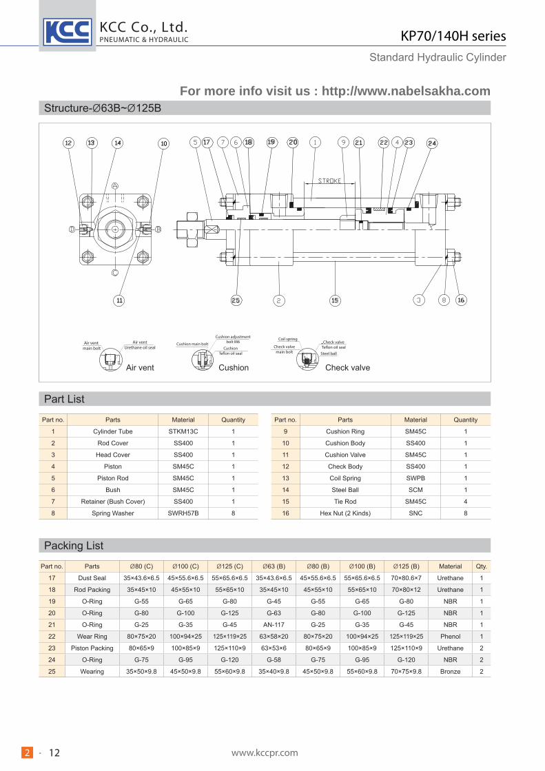
Dimensions-Rod Side Rectangular Flange (FA)
Unit : mm
Bore size
Bore size (B type) Bore size (C type)BB E EE EF F FB LF LL LZ R TF UF W WF YP
A B D KK MM A B D KK MM
40 30 40 20 M20X1.5 22 25 36 16 M16X1.5 18 15 65 Rc(PT)3/8 69 11 11 141 130 166 46 95 118 30 41 27
50 35 46 24 M24X1.5 28 30 40 20 M20X1.5 22 15 75 Rc(PT)1/2 85 13 14 155 142 182 58 115 145 30 43 29
63 45 55 30 M30X1.5 35 35 46 24 M24X1.5 28 17 90 Rc(PT)1/2 98 15 18 163 148 194 65 132 165 35 50 31
80 60 65 41 M39X1.5 45 45 55 31 M30X1.5 35 23 110 Rc(PT)3/4 118 18 18 184 166 222 87 155 190 35 53 38
100 75 80 50 M48X1.5 55 60 65 41 M39X1.5 45 26 135 Rc(PT)3/4 150 20 22 192 172 232 109 190 230 40 60 38
125 95 95 65 M64X2 70 75 80 50 M48X1.5 55 30 165 Rc(PT)1 175 24 26 220 196 264 130 224 272 45 69 43
140 110 105 75 M72X2 80 80 85 60 M56X2 65 35 185 Rc(PT)1 195 26 26 230 204 276 145 250 300 50 76 43
150 115 110 80 M76X2 85 85 90 60 M60X2 65 35 196 Rc(PT)1 210 28 30 240 212 288 155 270 320 50 78 43
160 120 115 85 M80X2 90 95 95 65 M64X2 70 35 210 Rc(PT)1 225 31 33 253 222 304 170 285 345 55 86 43
180 140 125 - M95X2 100 110 105 75 M72X2 80 40 235 Rc(PT)1 1/4 243 33 33 275 242 - 185 315 375 55 88 42
200 150 140 - M100X2 112 120 115 85 M80X2 90 40 262 Rc(PT)1 1/2 272 37 36 301 264 - 206 355 425 55 92 48
250 195 170 - M130X2 140 150 140 - M100X2 112 50 325 Rc(PT)2 335 46 45 346 300 - 250 425 515 65 111 60
For not shown dimensions, refer to SD type (standard type).
Double rod type ( 40 ~ 160)
70kgf/cm2
Bore size MF DF
100 97 12
110 109 15
140 137 15
D:Width cross flat (for spanner)
To the bore size of 100 a hole is placed with the width cross flat.
Shape varies depending on bore sizes.
Unit:mm
Bore size ~1500 1501~2000
80~ 250 Tie rod type Tube flange type
For more info visit us : http://www.nabelsakha.com
KCC Co., Ltd.
www.kccpr.com 182 -
PNEUMATIC & HYDRAULIC KP70/140H seriesStandard Hydraulic Cylinder
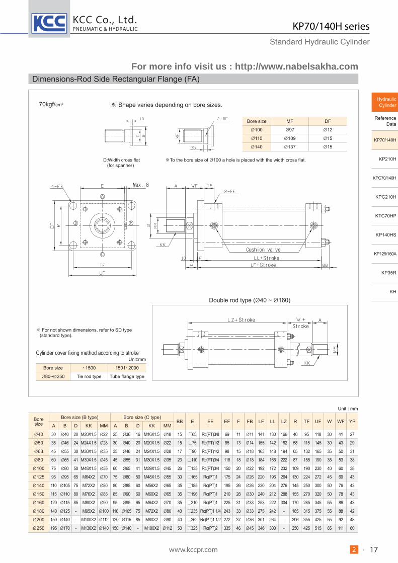
Dimensions-Head Side Rectangular Flange (FB)
Unit : mm
Bore sizeBore size (B type) Bore size (C type)
E EE EF F FB FP LF LZ R TF UF W ZFA B D KK MM A B D KK MM
40 30 40 20 M20X1.5 22 25 36 16 M16X1.5 18 65 Rc(PT)3/8 69 11 11 38 141 166 46 95 118 30 182
50 35 46 24 M24X1.5 28 30 40 20 M20X1.5 22 75 Rc(PT)1/2 85 13 14 42 155 182 58 115 145 30 198
63 45 55 30 M30X1.5 35 35 46 24 M24X1.5 28 90 Rc(PT)1/2 98 15 18 46 163 194 65 132 165 35 213
80 60 65 41 M39X1.5 45 45 55 31 M30X1.5 35 110 Rc(PT)3/4 118 18 18 56 184 222 87 155 190 35 237
100 75 80 50 M48X1.5 55 60 65 41 M39X1.5 45 135 Rc(PT)3/4 150 20 22 58 192 232 109 190 230 40 252
125 95 95 65 M64X2 70 75 80 50 M48X1.5 55 165 Rc(PT)1 175 24 26 67 220 264 130 224 272 45 289
140 110 105 75 M72X2 80 80 85 60 M56X2 65 185 Rc(PT)1 195 26 26 69 230 276 145 250 300 50 306
150 115 110 80 M76X2 85 85 90 60 M60X2 65 196 Rc(PT)1 210 28 30 71 240 288 155 270 320 50 318
160 120 115 85 M80X2 90 95 95 65 M64X2 70 210 Rc(PT)1 225 31 33 74 253 304 170 285 345 55 339
180 140 125 - M95X2 100 110 105 75 M72X2 80 235 Rc(PT)1 1/4 243 33 33 75 275 - 185 315 375 55 363
200 150 140 - M100X2 112 120 115 85 M80X2 90 262 Rc(PT)1 1/2 272 37 36 85 301 - 206 355 425 55 393
250 195 170 - M130X2 140 150 140 - M100X2 112 325 Rc(PT)2 335 46 45 106 346 - 250 425 515 65 457
Double rod type ( 40 ~ 160)
70kgf/cm2 140kgf/cm2
Bore size MF DF
100 97 12
110 109 15
140 137 15
D:Width cross flat (for spanner)
To the bore size of 100 a hole is placed with the width cross flat.
Shape varies depending on bore sizes.
For not shown dimensions, refer to SD type (standard type).
Unit:mm
Bore size ~1500 1501~2000
80~ 250 Tie rod type Tube flange type
For more info visit us : http://www.nabelsakha.com
KCC Co., Ltd.
www.kccpr.com 192 -
PNEUMATIC & HYDRAULIC
Hydraulic Cylinder
Reference Data
KP70/140H
KP210H
KPC70/140H
KPC210H
KTC70HP
KP140HS
KP125/160A
KP35R
KH
KP70/140H seriesStandard Hydraulic Cylinder
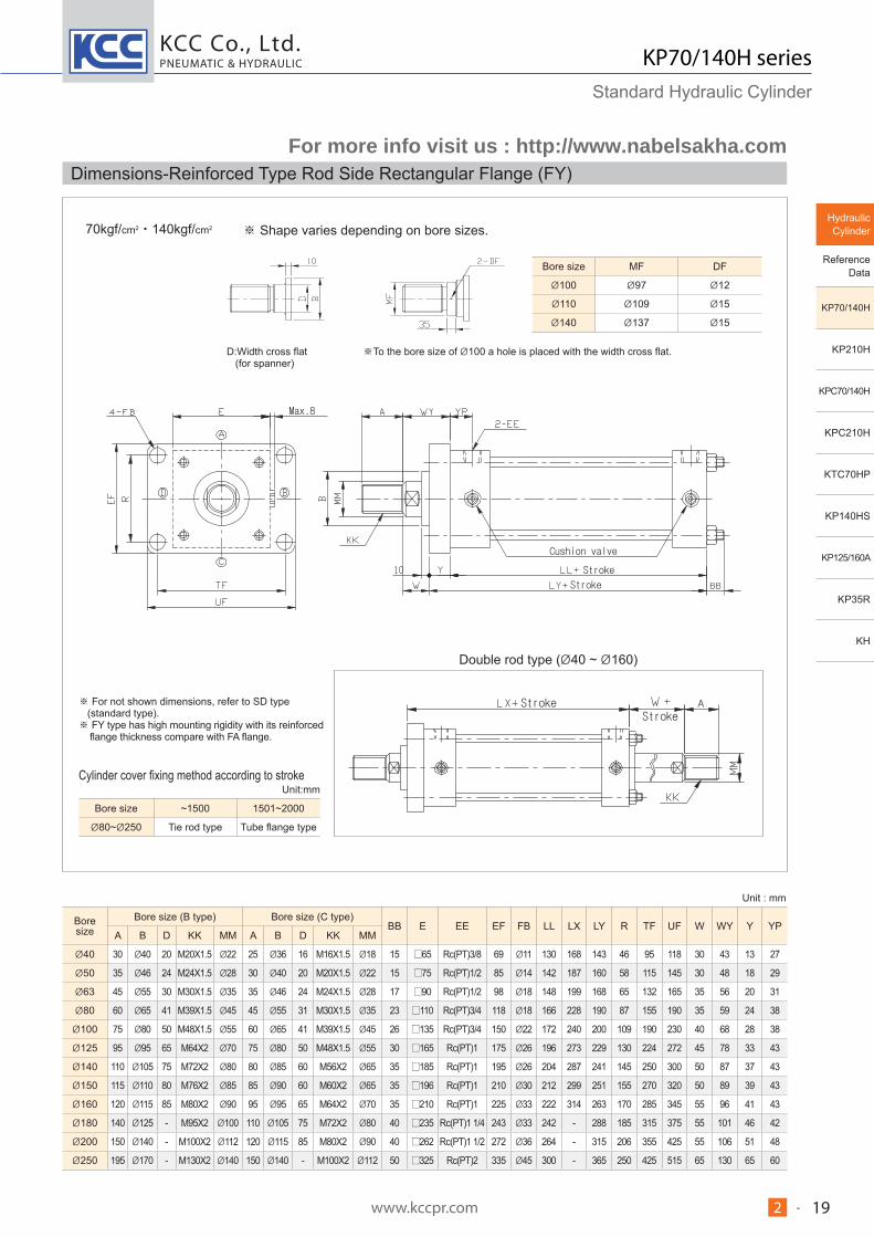
Dimensions-Reinforced Type Rod Side Rectangular Flange (FY)
Unit : mm
Bore size
Bore size (B type) Bore size (C type)BB E EE EF FB LL LX LY R TF UF W WY Y YP
A B D KK MM A B D KK MM
40 30 40 20 M20X1.5 22 25 36 16 M16X1.5 18 15 65 Rc(PT)3/8 69 11 130 168 143 46 95 118 30 43 13 27
50 35 46 24 M24X1.5 28 30 40 20 M20X1.5 22 15 75 Rc(PT)1/2 85 14 142 187 160 58 115 145 30 48 18 29
63 45 55 30 M30X1.5 35 35 46 24 M24X1.5 28 17 90 Rc(PT)1/2 98 18 148 199 168 65 132 165 35 56 20 31
80 60 65 41 M39X1.5 45 45 55 31 M30X1.5 35 23 110 Rc(PT)3/4 118 18 166 228 190 87 155 190 35 59 24 38
100 75 80 50 M48X1.5 55 60 65 41 M39X1.5 45 26 135 Rc(PT)3/4 150 22 172 240 200 109 190 230 40 68 28 38
125 95 95 65 M64X2 70 75 80 50 M48X1.5 55 30 165 Rc(PT)1 175 26 196 273 229 130 224 272 45 78 33 43
140 110 105 75 M72X2 80 80 85 60 M56X2 65 35 185 Rc(PT)1 195 26 204 287 241 145 250 300 50 87 37 43
150 115 110 80 M76X2 85 85 90 60 M60X2 65 35 196 Rc(PT)1 210 30 212 299 251 155 270 320 50 89 39 43
160 120 115 85 M80X2 90 95 95 65 M64X2 70 35 210 Rc(PT)1 225 33 222 314 263 170 285 345 55 96 41 43
180 140 125 - M95X2 100 110 105 75 M72X2 80 40 235 Rc(PT)1 1/4 243 33 242 - 288 185 315 375 55 101 46 42
200 150 140 - M100X2 112 120 115 85 M80X2 90 40 262 Rc(PT)1 1/2 272 36 264 - 315 206 355 425 55 106 51 48
250 195 170 - M130X2 140 150 140 - M100X2 112 50 325 Rc(PT)2 335 45 300 - 365 250 425 515 65 130 65 60
Double rod type ( 40 ~ 160)
70kgf/cm2 140kgf/cm2
Bore size MF DF
100 97 12
110 109 15
140 137 15
D:Width cross flat (for spanner)
To the bore size of 100 a hole is placed with the width cross flat.
Shape varies depending on bore sizes.
For not shown dimensions, refer to SD type (standard type).
FY type has high mounting rigidity with its reinforced flange thickness compare with FA flange.
Unit:mm
Bore size ~1500 1501~2000
80~ 250 Tie rod type Tube flange type
For more info visit us : http://www.nabelsakha.com
KCC Co., Ltd.
www.kccpr.com 202 -
PNEUMATIC & HYDRAULIC KP70/140H seriesStandard Hydraulic Cylinder
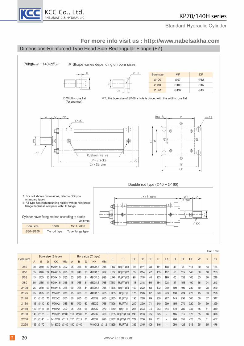
Dimensions-Reinforced Type Head Side Rectangular Flange (FZ)
Unit : mm
Bore sizeBore size (B type) Bore size (C type)
E EE EF FB FP LF LX R TF UF W Y ZYA B D KK MM A B D KK MM
40 30 40 20 M20X1.5 22 25 36 16 M16X1.5 18 65 Rc(PT)3/8 69 11 38 141 168 46 95 118 30 13 184
50 35 46 24 M24X1.5 28 30 40 20 M20X1.5 22 75 Rc(PT)1/2 85 14 42 155 187 58 115 145 30 18 203
63 45 55 30 M30X1.5 35 35 46 24 M24X1.5 28 90 Rc(PT)1/2 98 18 46 163 199 65 132 165 35 20 218
80 60 65 41 M39X1.5 45 45 55 31 M30X1.5 35 110 Rc(PT)3/4 118 18 56 184 228 87 155 190 35 24 243
100 75 80 50 M48X1.5 55 60 65 41 M39X1.5 45 135 Rc(PT)3/4 150 22 58 192 240 109 190 230 40 28 260
125 95 95 65 M64X2 70 75 80 50 M48X1.5 55 165 Rc(PT)1 175 26 67 220 273 130 224 272 45 33 298
140 110 105 75 M72X2 80 80 85 60 M56X2 65 185 Rc(PT)1 195 26 69 230 287 145 250 300 50 37 317
150 115 110 80 M76X2 85 85 90 60 M60X2 65 196 Rc(PT)1 210 30 71 240 299 155 270 320 50 39 329
160 120 115 85 M80X2 90 95 95 65 M64X2 70 210 Rc(PT)1 225 33 74 253 314 170 285 345 55 41 349
180 140 125 - M95X2 100 110 105 75 M72X2 80 235 Rc(PT)1 1/4 243 33 75 275 - 185 315 375 55 46 376
200 150 140 - M100X2 112 120 115 85 M80X2 90 262 Rc(PT)1 1/2 272 36 85 301 - 206 355 425 55 51 407
250 195 170 - M130X2 140 150 140 - M100X2 112 325 Rc(PT)2 335 45 106 346 - 250 425 515 65 65 476
Double rod type ( 40 ~ 160)
70kgf/cm2 140kgf/cm2
Bore size MF DF
100 97 12
110 109 15
140 137 15
D:Width cross flat (for spanner)
To the bore size of 100 a hole is placed with the width cross flat.
Shape varies depending on bore sizes.
For not shown dimensions, refer to SD type (standard type).
FZ type has high mounting rigidity with its reinforced flange thickness compare with FB flange.
Unit:mm
Bore size ~1500 1501~2000
80~ 250 Tie rod type Tube flange type
For more info visit us : http://www.nabelsakha.com
KCC Co., Ltd.
www.kccpr.com 212 -
PNEUMATIC & HYDRAULIC
Hydraulic Cylinder
Reference Data
KP70/140H
KP210H
KPC70/140H
KPC210H
KTC70HP
KP140HS
KP125/160A
KP35R
KH
KP70/140H seriesStandard Hydraulic Cylinder
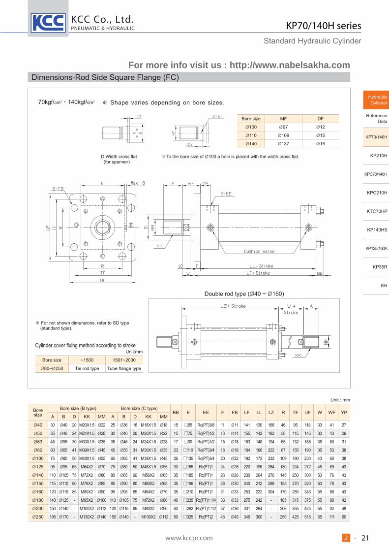
Dimensions-Rod Side Square Flange (FC)
Unit : mm
Bore size
Bore size (B type) Bore size (C type)BB E EE F FB LF LL LZ R TF UF W WF YP
A B D KK MM A B D KK MM
40 30 40 20 M20X1.5 22 25 36 16 M16X1.5 18 15 65 Rc(PT)3/8 11 11 141 130 166 46 95 118 30 41 27
50 35 46 24 M24X1.5 28 30 40 20 M20X1.5 22 15 75 Rc(PT)1/2 13 14 155 142 182 58 115 145 30 43 29
63 45 55 30 M30X1.5 35 35 46 24 M24X1.5 28 17 90 Rc(PT)1/2 15 18 163 148 194 65 132 165 35 50 31
80 60 65 41 M39X1.5 45 45 55 31 M30X1.5 35 23 110 Rc(PT)3/4 18 18 184 166 222 87 155 190 35 53 38
100 75 80 50 M48X1.5 55 60 65 41 M39X1.5 45 26 135 Rc(PT)3/4 20 22 192 172 232 109 190 230 40 60 38
125 95 95 65 M64X2 70 75 80 50 M48X1.5 55 30 165 Rc(PT)1 24 26 220 196 264 130 224 272 45 69 43
140 110 105 75 M72X2 80 80 85 60 M56X2 65 35 185 Rc(PT)1 26 26 230 204 276 145 250 300 50 76 43
150 115 110 80 M76X2 85 85 90 60 M60X2 65 35 196 Rc(PT)1 28 30 240 212 288 155 270 320 50 78 43
160 120 115 85 M80X2 90 95 95 65 M64X2 70 35 210 Rc(PT)1 31 33 253 222 304 170 285 345 55 86 43
180 140 125 - M95X2 100 110 105 75 M72X2 80 40 235 Rc(PT)1 1/4 33 33 275 242 - 185 315 375 55 88 42
200 150 140 - M100X2 112 120 115 85 M80X2 90 40 262 Rc(PT)1 1/2 37 36 301 264 - 206 355 425 55 92 48
250 195 170 - M130X2 140 150 140 - M100X2 112 50 325 Rc(PT)2 46 45 346 300 - 250 425 515 65 111 60
Double rod type ( 40 ~ 160)
70kgf/cm2 140kgf/cm2
Bore size MF DF
100 97 12
110 109 15
140 137 15
D:Width cross flat (for spanner)
To the bore size of 100 a hole is placed with the width cross flat.
Shape varies depending on bore sizes.
For not shown dimensions, refer to SD type (standard type).
Unit:mm
Bore size ~1500 1501~2000
80~ 250 Tie rod type Tube flange type
For more info visit us : http://www.nabelsakha.com

KCC Co., Ltd.
www.kccpr.com 222 -
PNEUMATIC & HYDRAULIC KP70/140H seriesStandard Hydraulic Cylinder
Dimensions-Head Side Square Flange (FD)
Unit : mm
Bore sizeBore size (B type) Bore size (C type)
E EE F FB FP LF LZ R TF UF W ZFA B D KK MM A B D KK MM
40 30 40 20 M20X1.5 22 25 36 16 M16X1.5 18 65 Rc(PT)3/8 11 11 38 141 166 46 95 118 30 182
50 35 46 24 M24X1.5 28 30 40 20 M20X1.5 22 75 Rc(PT)1/2 13 14 42 155 182 58 115 145 30 198
63 45 55 30 M30X1.5 35 35 46 24 M24X1.5 28 90 Rc(PT)1/2 15 18 46 163 194 65 132 165 35 213
80 60 65 41 M39X1.5 45 45 55 31 M30X1.5 35 110 Rc(PT)3/4 18 18 56 184 222 87 155 190 35 237
100 75 80 50 M48X1.5 55 60 65 41 M39X1.5 45 135 Rc(PT)3/4 20 22 58 192 232 109 190 230 40 252
125 95 95 65 M64X2 70 75 80 50 M48X1.5 55 165 Rc(PT)1 24 26 67 220 264 130 224 272 45 289
140 110 105 75 M72X2 80 80 85 60 M56X2 65 185 Rc(PT)1 26 26 69 230 276 145 250 300 50 306
150 115 110 80 M76X2 85 85 90 60 M60X2 65 196 Rc(PT)1 28 30 71 240 288 155 270 320 50 318
160 120 115 85 M80X2 90 95 95 65 M64X2 70 210 Rc(PT)1 31 33 74 253 304 170 285 345 55 339
180 140 125 - M95X2 100 110 105 75 M72X2 80 235 Rc(PT)1 1/4 33 33 75 275 - 185 315 375 55 363
200 150 140 - M100X2 112 120 115 85 M80X2 90 262 Rc(PT)1 1/2 37 36 85 301 - 206 355 425 55 393
250 195 170 - M130X2 140 150 140 - M100X2 112 325 Rc(PT)2 46 45 106 346 - 250 425 515 65 457
Double rod type ( 40 ~ 160)
70kgf/cm2 140kgf/cm2
Bore size MF DF
100 97 12
110 109 15
140 137 15
D:Width cross flat (for spanner)
To the bore size of 100 a hole is placed with the width cross flat.
Shape varies depending on bore sizes.
For not shown dimensions, refer to SD type (standard type).
Unit:mm
Bore size ~1500 1501~2000
80~ 250 Tie rod type Tube flange type
For more info visit us : http://www.nabelsakha.com

KCC Co., Ltd.
www.kccpr.com 232 -
PNEUMATIC & HYDRAULIC
Hydraulic Cylinder
Reference Data
KP70/140H
KP210H
KPC70/140H
KPC210H
KTC70HP
KP140HS
KP125/160A
KP35R
KH
KP70/140H seriesStandard Hydraulic Cylinder
Dimensions-Single Clevis (CA)
Unit : mm
Bore size
Bore size (B type) Bore size (C type)CD E EE EW FP L LF LR MR P W XC ZC
A B D KK MM A B D KK MM
40 30 40 20 M20X1.5 22 25 36 16 M16X1.5 18 16H9 65 Rc(PT)3/8 25 -0.1 38 38 141 R20 R16 90 30 209 225-0.4
50 35 46 24 M24X1.5 28 30 40 20 M20X1.5 22 20H9 75 Rc(PT)1/2 31.5 -0.1 42 45 155 R25 R20 98 30 230 250-0.4
63 45 55 30 M30X1.5 35 35 46 24 M24X1.5 28 31.5H9 90 Rc(PT)1/2 40 -0.1 46 63 163 R46 R31.5 102 35 261 292.5-0.4
80 60 65 41 M39X1.5 45 45 55 31 M30X1.5 35 31.5H9 110 Rc(PT)3/4 40 -0.1 56 72 184 R52 R31.5 110 35 291 322.5-0.4
100 75 80 50 M48X1.5 55 60 65 41 M39X1.5 45 40H9 135 Rc(PT)3/4 50 -0.1 58 84 192 R62 R40 116 40 316 356-0.4
125 95 95 65 M64X2 70 75 80 50 M48X1.5 55 50H9 165 Rc(PT)1 63 -0.1 67 100 220 R73 R50 130 45 365 415-0.4
140 110 105 75 M72X2 80 80 85 60 M56X2 65 63H9 185 Rc(PT)1 80 -0.1 69 120 230 R91 R63 138 50 400 463-0.6
150 115 110 80 M76X2 85 85 90 60 M60X2 65 63H9 196 Rc(PT)1 80 -0.1 71 122 240 R91 R63 146 50 412 475-0.6
160 120 115 85 M80X2 90 95 95 65 M64X2 70 71H9 210 Rc(PT)1 80 -0.1 74 137 253 R103 R71 156 55 445 516-0.6
180 140 125 - M95X2 100 110 105 75 M72X2 80 80H9 235 Rc(PT)1 1/4 100 -0.1 75 150 275 R100 R80 172 55 480 560-0.6
200 150 140 - M100X2 112 120 115 85 M80X2 90 90H9 262 Rc(PT)1 1/2 125 -0.1 85 170 301 R115 R90 184 55 526 616-0.6
250 195 170 - M130X2 140 150 140 - M100X2 112 100H9 325 Rc(PT)2 125 -0.1 106 185 346 R125 R100 200 65 596 696-0.6
For not shown dimensions, refer to SD type (standard type).
70kgf/cm2 140kgf/cm2
Bore size MF DF
100 97 12
110 109 15
140 137 15
D:Width cross flat (for spanner)
To the bore size of 100 a hole is placed with the width cross flat.
Shape varies depending on bore sizes.
Unit:mm
Bore size ~1500 1501~2000
80~ 250 Tie rod type Tube flange type
For more info visit us : http://www.nabelsakha.com

KCC Co., Ltd.
www.kccpr.com 242 -
PNEUMATIC & HYDRAULIC KP70/140H seriesStandard Hydraulic Cylinder
Dimensions-Double Clevis (CB)
Unit : mm
Bore size
Bore size (B type) Bore size (C type)CD E EE EW FP L LF LR MR P UB W XC ZC
A B D KK MM A B D KK MM
40 30 40 20 M20X1.5 22 25 36 16 M16X1.5 18 16H9 65 Rc(PT)3/8 25 -0.1 38 38 141 R20 R16 90 50 30 209 225-0.4
50 35 46 24 M24X1.5 28 30 40 20 M20X1.5 22 20H9 75 Rc(PT)1/2 31.5 -0.1 42 45 155 R25 R20 98 63.5 30 230 250-0.4
63 45 55 30 M30X1.5 35 35 46 24 M24X1.5 28 31.5H9 90 Rc(PT)1/2 40 -0.1 46 63 163 R46 R31.5 102 80 35 261 292.5-0.4
80 60 65 41 M39X1.5 45 45 55 31 M30X1.5 35 31.5H9 110 Rc(PT)3/4 40 -0.1 56 72 184 R52 R31.5 110 80 35 291 322.5-0.4
100 75 80 50 M48X1.5 55 60 65 41 M39X1.5 45 40H9 135 Rc(PT)3/4 50 -0.1 58 84 192 R62 R40 116 100 40 316 356-0.4
125 95 95 65 M64X2 70 75 80 50 M48X1.5 55 50H9 165 Rc(PT)1 63 -0.1 67 100 220 R73 R50 130 126 45 365 415-0.4
140 110 105 75 M72X2 80 80 85 60 M56X2 65 63H9 185 Rc(PT)1 80 -0.1 69 120 230 R91 R63 138 160 50 400 463-0.6
150 115 110 80 M76X2 85 85 90 60 M60X2 65 63H9 196 Rc(PT)1 80 -0.1 71 122 240 R91 R63 146 160 50 412 475-0.6
160 120 115 85 M80X2 90 95 95 65 M64X2 70 71H9 210 Rc(PT)1 80 -0.1 74 137 253 R103 R71 156 160 55 445 516-0.6
180 140 125 - M95X2 100 110 105 75 M72X2 80 80H9 235 Rc(PT)1 1/4 100 -0.1 75 150 275 R100 R80 172 200 55 480 560-0.6
200 150 140 - M100X2 112 120 115 85 M80X2 90 90H9 262 Rc(PT)1 1/2 125 -0.1 85 170 301 R115 R90 184 251 55 526 616-0.6
250 195 170 - M130X2 140 150 140 - M100X2 112 100H9 325 Rc(PT)2 125 -0.1 106 185 346 R125 R100 200 251 65 596 696-0.6
For not shown dimensions, refer to SD type(standard type).
70kgf/cm2 140kgf/cm2
Bore size MF DF
100 97 12
110 109 15
140 137 15
D:Width cross flat (for spanner)
To the bore size of 100 a hole is placed with the width cross flat.
Shape varies depending on bore sizes.
Unit:mm
Bore size ~1500 1501~2000
80~ 250 Tie rod type Tube flange type
For more info visit us : http://www.nabelsakha.com

KCC Co., Ltd.
www.kccpr.com 252 -
PNEUMATIC & HYDRAULIC
Hydraulic Cylinder
Reference Data
KP70/140H
KP210H
KPC70/140H
KPC210H
KTC70HP
KP140HS
KP125/160A
KP35R
KH
KP70/140H seriesStandard Hydraulic Cylinder
Dimensions-Center Trunnion (TC)
Unit : mm
Bore size
Bore size (B type) Bore size (C type)BB BD E EE FP LF LZ PH TD TL TM TR UM W XI ZJ
A B D KK MM A B D KK MM
40 30 40 20 M20X1.5 22 25 36 16 M16X1.5 18 15 28 65 Rc(PT)3/8 38 141 166 105 20e9 20 69 0 2 109 30 113 171-0.3
50 35 46 24 M24X1.5 28 30 40 20 M20X1.5 22 15 33 75 Rc(PT)1/2 42 155 182 113.5 25e9 25 85 0 2.5 135 30 121 185-0.35
63 45 55 30 M30X1.5 35 35 46 24 M24X1.5 28 17 43 90 Rc(PT)1/2 46 163 194 127.5 31.5e9 31.5 98 0 2.5 161 35 132 198-0.35
80 60 65 41 M39X1.5 45 45 55 31 M30X1.5 35 23 43 110 Rc(PT)3/4 56 184 222 140.5 31.5e9 31.5 118 0 2.5 181 35 146 219-0.35
100 75 80 50 M48X1.5 55 60 65 41 M39X1.5 45 26 53 135 Rc(PT)3/4 58 192 232 152.5 40e9 40 145 0 3 225 40 156 232-0.4
125 95 95 65 M64X2 70 75 80 50 M48X1.5 55 30 58 165 Rc(PT)1 67 220 264 174 50e9 50 175 0 3 275 45 177 265-0.46
140 110 105 75 M72X2 80 80 85 60 M56X2 65 35 78 185 Rc(PT)1 69 230 276 191 63e9 63 195 0 4 321 50 188 280-0.46
150 115 110 80 M76X2 85 85 90 60 M60X2 65 35 78 196 Rc(PT)1 71 240 288 193 63e9 63 206 0 4 332 50 194 290-0.46
160 120 115 85 M80X2 90 95 95 65 M64X2 70 35 88 210 Rc(PT)1 74 253 304 211 71e9 71 218 0 4 360 55 207 308-0.46
180 140 125 - M95X2 100 110 105 75 M72X2 80 40 98 235 Rc(PT)1 1/4 75 275 - 222 80e9 80 243 0 4 403 55 216 330-0.46
200 150 140 - M100X2 112 120 115 85 M80X2 90 40 108 262 Rc(PT)1 1/2 85 301 - 241 90e9 90 272 0 5 452 55 232 356-0.52
250 195 170 - M130X2 140 150 140 - M100X2 112 50 117 325 Rc(PT)2 106 346 - 284.5 100e9 100 335 0 5 535 65 271 411-0.57
For not shown dimensions, refer to SD type (standard type).
Double rod type ( 40 ~ 160)
70kgf/cm2 140kgf/cm2
Bore size MF DF
100 97 12
110 109 15
140 137 15
D:Width across flat (for spanner)
To the bore size of 100 a hole is placed with the width cross flat.
Shape varies depending on bore sizes.
Unit:mm
Bore size ~1500 1501~2000
80~ 250 Tie rod type Tube flange type
For more info visit us : http://www.nabelsakha.com

KCC Co., Ltd.
www.kccpr.com 262 -
PNEUMATIC & HYDRAULIC KP70/140H seriesStandard Hydraulic Cylinder
Dimensions-Rod Side Trunnion (TA)
Unit : mm
Bore size
Bore size (B type) Bore size (C type)BB E EE FP LF LZ TD TL TM TR UM W XG ZJ
A B D KK MM A B D KK MM
40 30 40 20 M20X1.5 22 25 36 16 M16X1.5 18 15 65 Rc(PT)3/8 38 141 166 20e9 20 69 0 2 109 30 62 171-0.3
50 35 46 24 M24X1.5 28 30 40 20 M20X1.5 22 15 75 Rc(PT)1/2 42 155 182 25e9 25 85 0 2.5 135 30 66 185-0.35
63 45 55 30 M30X1.5 35 35 46 24 M24X1.5 28 17 90 Rc(PT)1/2 46 163 194 31.5e9 31.5 98 0 2.5 161 35 74 198-0.35
80 60 65 41 M39X1.5 45 45 55 31 M30X1.5 35 23 110 Rc(PT)3/4 56 184 222 31.5e9 31.5 118 0 2.5 181 35 82 219-0.35
100 75 80 50 M48X1.5 55 60 65 41 M39X1.5 45 26 135 Rc(PT)3/4 58 192 232 40e9 40 145 0 3 225 40 89 232-0.4
125 95 95 65 M64X2 70 75 80 50 M48X1.5 55 30 165 Rc(PT)1 67 220 264 50e9 50 175 0 3 275 45 103 265-0.46
140 110 105 75 M72X2 80 80 85 60 M56X2 65 35 185 Rc(PT)1 69 230 276 63e9 63 195 0 4 321 50 112 280-0.46
150 115 110 80 M76X2 85 85 90 60 M60X2 65 35 196 Rc(PT)1 71 240 288 63e9 63 206 0 4 332 50 112 290-0.46
160 120 115 85 M80X2 90 95 95 65 M64X2 70 35 210 Rc(PT)1 74 253 304 71e9 71 218 0 4 360 55 126 308-0.46
For not shown dimensions, refer to SD type (standard type).
Cushion valve and air vent location of TA type is C. (Rod cover)
Double rod type ( 40 ~ 160)
70kgf/cm2 140kgf/cm2
Bore size MF DF
100 97 12
110 109 15
140 137 15
D:Width cross flat (for spanner)
To the bore size of 100 a hole is placed with the width cross flat.
Shape varies depending on bore sizes.
Unit:mm
Bore size ~1500 1501~2000
80~ 250 Tie rod type Tube flange type
For more info visit us : http://www.nabelsakha.com
KCC Co., Ltd.
www.kccpr.com 272 -
PNEUMATIC & HYDRAULIC
Hydraulic Cylinder
Reference Data
KP70/140H
KP210H
KPC70/140H
KPC210H
KTC70HP
KP140HS
KP125/160A
KP35R
KH
KP70/140H seriesStandard Hydraulic Cylinder
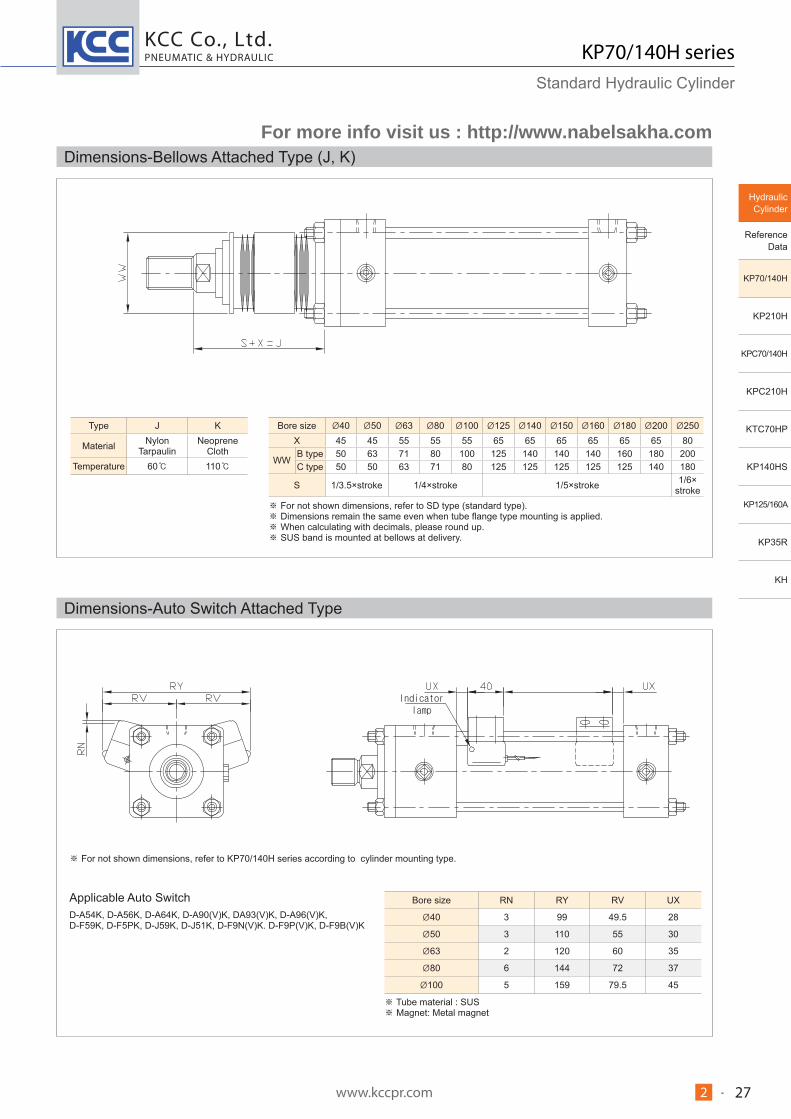
Dimensions-Bellows Attached Type (J, K)
Type J K
Material Nylon Tarpaulin
Neoprene Cloth
Temperature 60 110
Bore size 40 50 63 80 100 125 140 150 160 180 200 250X 45 45 55 55 55 65 65 65 65 65 65 80
WWB type 50 63 71 80 100 125 140 140 140 160 180 200C type 50 50 63 71 80 125 125 125 125 125 140 180
S 1/3.5×stroke 1/4×stroke 1/5×stroke 1/6× stroke
For not shown dimensions, refer to SD type (standard type). Dimensions remain the same even when tube flange type mounting is applied. When calculating with decimals, please round up. SUS band is mounted at bellows at delivery.
Dimensions-Auto Switch Attached Type
Bore size RN RY RV UX
40 3 99 49.5 28
50 3 110 55 30
63 2 120 60 35
80 6 144 72 37
100 5 159 79.5 45
Tube material : SUS Magnet: Metal magnet
For not shown dimensions, refer to KP70/140H series according to cylinder mounting type.
Applicable Auto SwitchD-A54K, D-A56K, D-A64K, D-A90(V)K, DA93(V)K, D-A96(V)K,D-F59K, D-F5PK, D-J59K, D-J51K, D-F9N(V)K. D-F9P(V)K, D-F9B(V)K
For more info visit us : http://www.nabelsakha.com

KCC Co., Ltd.
www.kccpr.com 282 -
PNEUMATIC & HYDRAULIC KP70/140H seriesStandard Hydraulic Cylinder
Unit : mm
Part no.CA CC CD CF CT CW ER FW J
KKRA
RF
B rod C rod B rod
C rodB rod C rod
Y(Hyd.)40B Y(Hyd.)40C 60 27 16 H10 32 50 12.5 16 25 +0.4 8 M20×1.5M16×1.5 76 32 27f8 +0.1
Y(Hyd.)50B Y(Hyd.)50C 70 32 20 H10 40 63.5 16 20 31.5 +0.4 10 M24×1.5M20×1.5 90 37 32f8 +0.1
Y(Hyd.)63B Y(Hyd.)63C 115 50 31.5 H10 60 80 20 30 40 +0.4 15 M30×1.5M24×1.5 145 47 37f8 +0.1
Y(Hyd.)80B Y(Hyd.)80C 115 50 31.5 H10 60 80 20 30 40 +0.4 15 M39×1.5M30×1.5 145 62 47f8 +0.1
Y(Hyd.)100B Y(Hyd.)100C 145 60 40 H10 80 100 25 40 50 +0.4 20 M48×1.5M39×1.5 185 77 62f8 +0.1
Y(Hyd.)125B Y(Hyd.)125C 180 70 50 H10 100 12631.5 50 63 +0.4 30 M64×2 M48×1.5 230 97 77f8 +0.1
Y(Hyd.)140B Y(Hyd.)140C 225 90 63 H10 120 160 40 65 80 +0.4 30 M72×2 M56×2 290 112 82f8 +0.1
Y(Hyd.)150B Y(Hyd.)150C 225 90 63 H10 120 160 40 65 80 +0.4 30 M76×2 M60×2 290 117 87f8 +0.1
Y(Hyd.)160B Y(Hyd.)160C 240 100 71 H10 140 160 40 70 80 +0.4 40 M80×2 M64×2 310 122 97f8 +0.1
Unit : mmPart no. B type rod end nut C type rod end nut
B rod C rod d B C H d B C HRN(Hyd.)40B RN(Hyd.)40C M20×1.5 30 34.6 12 M16×1.5 24 27.5 10RN(Hyd.)50B RN(Hyd.)50C M24×1.5 36 41.6 14 M20×1.5 30 34.6 12RN(Hyd.)63B RN(Hyd.)63C M30×1.5 46 53.1 18 M24×1.5 36 41.6 14RN(Hyd.)80B RN(Hyd.)80C M39×1.5 60 69.3 23 M30×1.5 46 53.1 18RN(Hyd.)100B RN(Hyd.)100C M48×1.5 75 86.5 29 M39×1.5 60 69.3 23RN(Hyd.)125B RN(Hyd.)125C M64×2 95 110 38 M48×1.5 75 86.5 29RN(Hyd.)140B RN(Hyd.)140C M72×2 100 - 38 M56×2 85 - 30RN(Hyd.)150B RN(Hyd.)150C M76×2 105 - 40 M60×2 90 - 33RN(Hyd.)160B RN(Hyd.)160C M80×2 110 - 43 M64×2 95 110 38
Unit : mmPart no.
A B C D E F G HClevis pin Knuckle joint pin
CB PIN(Hyd.)40 Y PIN(Hyd.)40 16 14.7 25 5 50.5 9.5 2 65CB PIN(Hyd.)50 Y PIN(Hyd.)50 20 18.5 30 5 64 10 2 79CB PIN(Hyd.)63 Y PIN(Hyd.)63 31.5 30 40 5 80.5 9.5 2.5 95CB PIN(Hyd.)80 Y PIN(Hyd.)80 31.5 30 40 5 80.5 9.5 2.5 95CB PIN(Hyd.)100 Y PIN(Hyd.)100 40 37.5 50 5 100.5 9.5 2.5 115CB PIN(Hyd.)125 Y PIN(Hyd.)125 50 46.5 60 5 126.5 9.5 3 141CB PIN(Hyd.)140 Y PIN(Hyd.)140 63 58.5 70 10 161 9 3 180CB PIN(Hyd.)150 Y PIN(Hyd.)150 63 58.5 70 10 161 9 3 180CB PIN(Hyd.)160 Y PIN(Hyd.)160 71 66.5 80 10 161 9 3 180
Unit : mm
Part no.CA CC CD CF CT CW ER FW J
KKRA
RF
B rod C rod B rod C rod B rod
C rod
I(Hyd.)40B I(Hyd.)40C 60 23 16H10 39 50 12.5 20 25 -0.4 8 M20×1.5 M16×1.5 80 32 27-0.1
I(Hyd.)50B I(Hyd.)50C 70 28 20H10 49 63.5 16 25 31.5 -0.4 10 M24×1.5 M20×1.5 95 37 32-0.1
I(Hyd.)63B I(Hyd.)63C 115 43 31.5H10 62 80 20 35 40 -0.4 15 M30×1.5 M24×1.5 150 47 37-0.1
I(Hyd.)80B I(Hyd.)80C 115 43 31.5H10 62 80 20 35 40 -0.4 15 M39×1.5 M30×1.5 150 62 47-0.1
I(Hyd.)100B I(Hyd.)100C 145 55 40H10 79 100 25 40 50 -0.4 20 M48×1.5 M39×1.5 185 77 62-0.1
I(Hyd.)125B I(Hyd.)125C 180 65 50H10 100 126 31.5 50 63 -0.4 30 M64×2 M48×1.5 230 97 77-0.1
I(Hyd.)140B I(Hyd.)140C 225 85 63H10 130 160 40 65 80 -0.4 30 M72×2 M56×2 290 112 82-0.1
I(Hyd.)150B I(Hyd.)150C 225 85 63H10 130 160 40 65 80 -0.4 30 M76×2 M60×2 290 117 87-0.1
I(Hyd.)160B I(Hyd.)160C 240 90 71H10 140 160 40 70 80 -0.4 40 M80×2 M64×2 310 122 97-0.1
Dimensions-Accessory
Single Knuckle Joint
Double Knuckle Joint
Knuckle Joint Pin / Clevis Pin
Rod End Nut
For rod end nut attached type, longer thread length (dimension A) is required.
For more info visit us : http://www.nabelsakha.com