Katzir 25/4/17 15:41 Page 78 Variations and Combinations
37
Variations and Combinations Invention and Development of Quartz Clock Technologies at AT&T Shaul Katzir Quartz clock technologies played a central role in twentieth century timekeeping, telecommunication and society at large. This article explores the process of the invention and construction of the first quartz clock by Warren Marrison and his associate researchers at AT&T,who needed the clock to monitor the corporation’s self-maintained crystal-controlled frequency standard. The frequency standard was deemed essential for the needs of electronic telecommunication in the 1920s. Based on research notebooks and contemporary publications, this article examines the origins of the technology in the corporation’s earlier tuning-fork-frequency- standard, which included the first electronic clock. Providing a detailed examin- ation of the various electronic methods used by Marrison and his colleagues and their origins, the article examines the way the modern, scientifically educated inventor, working within a large industrial laboratory and enjoying its rich material and intellectual resources, collected, combined and adjusted the resources at his disposal to produce novelty. In the early 1920s, American Telephone and Telegraph Company (AT&T) decided that it needed a new reliable and accurate system for measuring the high frequencies used in radio and telephone communication. Such a system had to be based on a highly regular oscillator, i.e. an oscillator that vibrated at a constant rate and could thus serve as a primary frequency standard for measuring oscillations via comparison. Newly developed quartz crystal resonators, vibrating stably at tens of thousands cycles per second (Hz), were considered the best choice for such an oscillator. A technical obstacle, how- ever, prevented using the quartz oscillator as a primary frequency standard. Since frequency and time are inverse aspects of the same physical phenom- enon, a comparison to a clock, the most exact measuring standard at the time, Dr. Shaul Katzir, The Cohn Institute for the History and Philosophy of Science and Ideas, Tel Aviv University 69978 Tel Aviv, Israel. [email protected] ICON: Journal of the International Committee for the History of Technology, 22 (2016): 78–114. © 2017 by the International Committee for the History of Technology
Transcript of Katzir 25/4/17 15:41 Page 78 Variations and Combinations

Variations and CombinationsInvention and Development of Quartz Clock Technologies at
AT&T
Shaul Katzir
Quartz clock technologies played a central role in twentieth century timekeeping,telecommunication and society at large. This article explores the process of theinvention and construction of the first quartz clock by Warren Marrison and hisassociate researchers at AT&T, who needed the clock to monitor the corporation’sself-maintained crystal-controlled frequency standard. The frequency standard wasdeemed essential for the needs of electronic telecommunication in the 1920s. Basedon research notebooks and contemporary publications, this article examines theorigins of the technology in the corporation’s earlier tuning-fork-frequency-standard, which included the first electronic clock. Providing a detailed examin-ation of the various electronic methods used by Marrison and his colleagues andtheir origins, the article examines the way the modern, scientifically educatedinventor, working within a large industrial laboratory and enjoying its richmaterial and intellectual resources, collected, combined and adjusted the resources athis disposal to produce novelty.
In the early 1920s, American Telephone and Telegraph Company (AT&T)decided that it needed a new reliable and accurate system for measuring thehigh frequencies used in radio and telephone communication. Such a systemhad to be based on a highly regular oscillator, i.e. an oscillator that vibratedat a constant rate and could thus serve as a primary frequency standard formeasuring oscillations via comparison. Newly developed quartz crystalresonators, vibrating stably at tens of thousands cycles per second (Hz), wereconsidered the best choice for such an oscillator. A technical obstacle, how-ever, prevented using the quartz oscillator as a primary frequency standard.Since frequency and time are inverse aspects of the same physical phenom-enon, a comparison to a clock, the most exact measuring standard at the time,
Dr. Shaul Katzir, The Cohn Institute for the History and Philosophy of Science and Ideas, Tel AvivUniversity 69978 Tel Aviv, Israel. [email protected]
ICON: Journal of the International Committee for the History of Technology, 22 (2016): 78–114.
© 2017 by the International Committee for the History of Technology
Katzir 25/4/17 15:41 Page 78
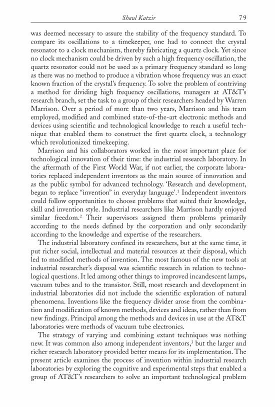
was deemed necessary to assure the stability of the frequency standard. Tocompare its oscillations to a timekeeper, one had to connect the crystalresonator to a clock mechanism, thereby fabricating a quartz clock. Yet sinceno clock mechanism could be driven by such a high frequency oscillation, thequartz resonator could not be used as a primary frequency standard so longas there was no method to produce a vibration whose frequency was an exactknown fraction of the crystal’s frequency. To solve the problem of contrivinga method for dividing high frequency oscillations, managers at AT&T’sresearch branch, set the task to a group of their researchers headed by WarrenMarrison. Over a period of more than two years, Marrison and his teamemployed, modified and combined state-of-the-art electronic methods anddevices using scientific and technological knowledge to reach a useful tech-nique that enabled them to construct the first quartz clock, a technologywhich revolutionized timekeeping.
Marrison and his collaborators worked in the most important place fortechnological innovation of their time: the industrial research laboratory. Inthe aftermath of the First World War, if not earlier, the corporate labora-tories replaced independent inventors as the main source of innovation andas the public symbol for advanced technology. ‘Research and development,began to replace “invention” in everyday language’.1 Independent inventorscould follow opportunities to choose problems that suited their knowledge,skill and invention style. Industrial researchers like Marrison hardly enjoyedsimilar freedom.2 Their supervisors assigned them problems primarilyaccording to the needs defined by the corporation and only secondarilyaccording to the knowledge and expertise of the researchers.
The industrial laboratory confined its researchers, but at the same time, itput richer social, intellectual and material resources at their disposal, whichled to modified methods of invention. The most famous of the new tools atindustrial researcher’s disposal was scientific research in relation to techno-logical questions. It led among other things to improved incandescent lamps,vacuum tubes and to the transistor. Still, most research and development inindustrial laboratories did not include the scientific exploration of naturalphenomena. Inventions like the frequency divider arose from the combina-tion and modification of known methods, devices and ideas, rather than fromnew findings. Principal among the methods and devices in use at the AT&Tlaboratories were methods of vacuum tube electronics.
The strategy of varying and combining extant techniques was nothingnew. It was common also among independent inventors,3 but the larger andricher research laboratory provided better means for its implementation. Thepresent article examines the process of invention within industrial researchlaboratories by exploring the cognitive and experimental steps that enabled agroup of AT&T’s researchers to solve an important technological problem
79Shaul Katzir
Katzir 25/4/17 15:41 Page 79

Invention and Development of Quartz Clock Technologies at AT&T
assigned to them. It focuses on the way modern, scientifically educatedinventors working within a large industrial laboratory collected, combinedand adjusted the rich resources at their disposal to produce novelty.
New electronic methods of radio and multiplex telephony required highaccuracy in frequency determination, levels of accuracy unprecedented intechnology up to that point. Moreover, exact knowledge of frequenciesbecame imperative for AT&T’s monopolistic strategy of providing an ‘inter-dependent, intercommunicating, universal system’. In practice, this ‘universalsystem’ was a highly complex network consisting of sub-systems using dif-ferent devices and methods which required the ability to coordinate andtransform messages from one device to the other. To control such a network,the corporation required a common standard for measuring the various elec-tric oscillations in use, which ranged from hundreds to millions of hertz. Itsresearch directors first adopted a frequency meter based on an electronicallymaintained tuning-fork as the basis for the company’s frequency standard.The tuning-fork technique had been invented and developed by the Frenchand the British in their research on improving radio communication formilitary needs during the First World War.4
The quartz oscillator was invented in 1921 and promised more regularvibrations and a simpler way to reach high frequencies than the tuning-forkmethod, but in order to use a quartz oscillator as a primary frequencystandard, Marrison and his colleagues needed to invent a method to divideits frequency by about 50 to 100 times. Marrison’s wasn’t the only teamworking on the problem. A similar interest in coordinating wireless com-munication – for purposes of regulation rather than control – led British andItalian national laboratories to develop their own methods for dividing thefrequency of quartz oscillators, which allowed the construction of clocks.Academic, commercial and military interests led three other groups in theUnited States, the Netherlands and Japan to develop frequency dividers thatcould be used to drive a quartz clock. These, however, lie beyond the scopeof the present article.5
While the quartz clock thus emerged from the needs of electronic com-munication, it later transformed timekeeping and significantly contributed tothe spread of ‘clock discipline’ in society at large. The quartz clock was thefirst to compete with and later exceed the accuracy of the pendulum clock,which had been improved for 250 years. From its beginnings as a laboratorydevice, the quartz clock ultimately reached virtually everyone in the affluentworld. Today, its precision accompanies and shapes daily life in clocks ofmany forms, mobile phones and virtually any electronic gadget. Moreover,quartz clock technology allowed broadcasting to expand and allowed thereforefor the distribution of precise time signals by radio. Consequently, the know-ledge of precise time became central to an increasing number of activities.6
80
Katzir 25/4/17 15:41 Page 80

While the present technical history of the quartz clock at AT&T does notexplain the broad consequences that the new technology had, it is needed forunderstanding the process by which modern technology is developed.
In developing its frequency measuring and standard system, AT&T builton advancements in the field made during the First World War. Itsresearchers first modified the tuning-fork-based system for the corporation’sneeds. This system served as a starting point and a model for its later quartzstandard. The first, shorter, part of the present article, therefore, discusses theresearch at AT&T on the tuning-fork frequency standard. Walter Cady’s1921 invention of a method for controlling the frequency of electronic cir-cuits by the steady vibrations of piezoelectric quartz resonators transformedthe field. By late 1924, AT&T deemed the new technology to be a viable andsuperior alternative for the tuning-fork standard, and Marrison’s team wastasked with driving a clock mechanism with a quartz oscillator. The secondpart of the article discusses Marrison’s various suggestions for dividing thehigh frequency of the quartz resonator, the construction of the full quartz-based frequency standard of AT&T, and the steps made to improve itsexactitude.
THE TUNING-FORK STANDARD
In early 1921, managers at AT&T concluded that ‘refinements of [the]methods [of electrical communication] have reached a point where it isimperative that determinations of the frequency of any . . . alternatingcurrents may be made with an accuracy considerably higher than has beenpossible hitherto’.7 These refinements followed the introduction of thetriode, an electronic vacuum tube with three electrodes, the central devicebeyond radio and electronics in general before the advent of the transistor inthe 1950s. Resembling an incandescent lamp, the glass surface of an elec-tronic vacuum tube encloses a space of low-density air (‘vacuum’) and two ormore electrodes: cathode that emitted electrons, anode that absorbed them,and in the case of a triode a ‘grid’ that enhanced or obstructed electric cur-rent (‘discharge’) according to the relation between its electric potential andthat of the cathode. Invented by Lee de Forest for receiving radio signal in1906, in 1912 a few individuals found ways to utilize the triode for amplify-ing electric signals and as an oscillator for emitting electromagnetic waves.AT&T bought rights for using the tube as an amplifier, which it needed forlong-distance telephone, and embarked on a research and development proj-ect for its improvement. As an oscillator the triode turned out to be highlyefficient for transmitting continuous radio waves, allowing wireless transmis-sion of voice and music. Attracting expanding attention shortly before thewar, the improvement of triodes and their circuits for amplification and oscil-
81Shaul Katzir
Katzir 25/4/17 15:41 Page 81

Invention and Development of Quartz Clock Technologies at AT&T
lation received larger human and material resources during WWI, becomingthe central component of the expanding radio communication, which wassuggested also as a complement for the wire telephone network.8
For connecting new wireless radio-telephony systems to the older wiredsystem, and for sending multiple calls on the same cable (see below), AT&Tneeded a better method to measure frequency. Its technical heads envisioneda new accurate and reliable frequency standard that would ‘cover the entirerange between a few cycles per second and several million’, and whose‘absolute value . . . is known to one part in 100,000’. They considered this aimfeasible due to the development of the tuning-fork-based method for fre-quency measurement during the First World War and its aftermath. Thetuning-fork method promised more stable oscillations and thus more accuratefrequency measurement than those using a resistor, coil and capacitor (RLC)circuit. In the new method, electromagnets (i.e. coils) connected to a triodeRLC circuit generated vibrations of a magnetized tuning-fork. The tuning-fork, which vibrated at its resonant (natural) frequency, produces an alter-nating electromagnetic field, which under suitable conditions forced theelectronic circuit to oscillate at the same frequency. Made for acoustics,tuning-forks oscillated at frequencies considerably lower than those used forradio. To use a tuning fork for measuring high frequencies, therefore, theFrench physicists Henri Abraham and Eugène Bloch, employed anotherdevice that they invented during the war: the multivibrator. Consisting of twotubes in which the the grid of each was connected to the anode of the otherthrough a capacitor, manually tuned by comparing its oscillations with that ofa tuning-fork circuit, the multivibrator generated oscillations at exact integralmultiplications of the tuning-fork’s frequency. Following the way that theoscillations appeared (and were heard) in acoustics, researchers on periodicphenomena dubbed such oscillations ‘harmonics’.
The task of constructing a measurement standard for AT&T was assignedto a group headed by Joseph Warren Horton,9 at the research branch ofAT&T – then a part of the engineering department of Western Electric.10
From 1925, the research branch merged with a few smaller units, formerlybelonging to other arms of the corporation (also referred as ‘the Bell system’),to become Bell Telephone Laboratories. ‘Bell Labs’, officially an independ-ent company, was however still totally owned by AT&T. The organizationalchanges did not affect the researchers, like Horton and his associates, alreadyworking at the Manhattan offices of the former research branch.
Born in 1889, Horton joined Western Electric in 1916, after studyingphysics and chemistry at MIT. When the United States joined the First WorldWar, Horton left for the Navy underwater laboratory in Nahant, Massa-chusetts. He regarded that period as part of his education because he workedwith notable scientists from General Electric and AT&T. After the war, he
82
Katzir 25/4/17 15:41 Page 82

returned to the research department of AT&T to work on advanced problemsin electrical communication. ‘Almost the only problem which was wholly under[his] control while at Bell Labs had to do with the measurement of frequency.’‘In general, these problems [on which he worked at AT&T] called for theutilization of existing knowledge rather than for the acquisition of new know-ledge.’11 Still, important parts of this knowledge had been recently acquired, ifmostly by researchers outside the Bell system. By December 1922, Hortonheaded a group of twenty-five employees, most of them probably with a firstdegree in physics or engineering, divided into four subgroups, one of themunder his direct responsibility. Only one or two of the smaller groups underHorton worked on frequency standards. Norman H. Ricker, a fresh PhD inphysics, headed one of these groups from summer 1921 to his departure fromAT&T at the beginning of 1923. A young subordinate who had alreadyworked on tuning-fork standards, Warren Marrison, succeeded Ricker.
Born in 1896, Marrison had earned a BSc in ‘engineering physics’ and usedhis experience as a radio amateur in the services of the Air Force of his nativeCanada, before working at Western Electric for the summer of 1920. InSeptember 1920, he registered for graduate studies in physics and math-ematics at Harvard, where he chose courses on a subject of much interest forAT&T: electric oscillations and their applications to radio. After he hadattained a Master’s degree, he returned to AT&T in September 1921.12 Eightmonths later, he joined the study of tuning forks, continuing the experi-mental work of one J. C. Davidson who had left the group. The quite easyreplacement of one researcher by another is a mark of the team approach ofthe group and AT&T’s laboratory in general. Although individuals oftenworked alone, or with one assistant or co-worker, the research was ultimatelyteamwork. Problems and questions were discussed in both official andinformal meetings and questions were allocated from one individual andeven from one unit to another.13
When Horton returned to Western Electric, he developed a means fortransmitting multiple messages on a single cable simultaneously, which wasknown as multiplex telephony (or telegraphy). The financial benefits of beingable to send multiple messages down a single line were obvious, as it wouldobviate the need for the multiplication of expensive copper wires. As thelargest telephone company in the world, with a monopoly in inter-city lines,AT&T had high stakes in the development of a multiplexer. In the versionon which Horton worked, a regular electric current produced by a telephonetransmitter was added to an electric oscillation of a higher frequency througha triode in a process called modulation. At the receiving end of the call, asimilar circuit ‘demodulated’ the current and yielded the original wave. Boththe transmitter and receiver needed to agree on the frequency of the oscil-lator, which set the frequency range of the transmission.
83Shaul Katzir
Katzir 25/4/17 15:41 Page 83

Invention and Development of Quartz Clock Technologies at AT&T84
While the principles of multiplexing were well-known at the time, a fewtechnical difficulties hampered its swift introduction into use. The productionof many known frequencies from a basic frequency was one of the techno-logical challenges of multiplexing. In 1920, Horton suggested a way to produce‘any required harmonic frequency wave, or a series of such waves from a givensine wave of fundamental frequency’. His scheme enabled the combination ofcircuits of different frequencies that are integer multiples of a basic frequencyto reach any integer multiplication of the original. This work provided himresources for developing Western Electric’s frequency standard, and probablycontributed to his appointment as head of its development.14
During 1921–1923, Horton’s group developed a compound system thatwould serve as a frequency standard for any radio wavelength used by AT&T.The system followed earlier systems for measuring radio frequencies like thatof Abraham and Bloch with a few significant changes and additions. Itincluded an electronic-tube-maintained tuning-fork that provided a funda-mental exact frequency, a ‘harmonic generator’ for multiplying this frequencyand modulators to reach intermediate frequencies between the valuesproduced by the harmonic generators. Since AT&T required a means tomeasure frequencies to within one hundred hertz, the group chose a tuning-fork with that natural resonance instead of the tuning-forks used by othergroups, which resonated at approximately one thousand hertz. It also decidedto design a new more complex harmonic generator to multiply the basictuning-fork frequency, in place of Abraham and Bloch’s multivibrator. Thisharmonic generator (also called a ‘harmonic producer’) multiplied the basicstandard frequency to its tenth harmonic, which went into a secondgenerator and into a third reaching one hundred thousand hertz. Electroniccircuits oscillated at each of these frequencies (in the later working system itsexact frequency could be tuned by a variable circuit). ‘Balance modulators’produced oscillations whose frequencies were the additions and subtractionsof the incoming frequencies. The scheme was similar to the one suggested byHorton in 1920 for multiplex telephony, showing the similarity between theprojects on multiplexing and frequency standards. Individual balancemodulators had already been used for telephony in the Bell system. Themodulators allowed the system to generate any intermediate frequency thatis an integer multiple of the fundamental 100Hz.15 The resulting oscillationcould be compared to and thus could measure the frequencies of otheroscillations. The system also included an ingredient of quality-control – amethod of comparing the basic frequency standard to a more reliable andknown standard, i.e. a pendulum clock.
Horton’s group developed the individual components of its system offrequency standards mostly in parallel to each other. Apparently, theelectronically driven tuning-fork was the earliest piece of the circuit to work;
Katzir 25/4/17 15:41 Page 84

the group had used it already before June 1921. A few of the group’s memberscontinued to improve it until the spring of 1922. In its design they relieddirectly on the suggestion of William Eccles in England and its improvementby E. Eckhardt et al. at the American Bureau of Standards. To prevent vari-ations in its frequency, the Bell group kept the tuning-fork under constanttemperature and pressure. The sensitivity of the tuning-fork’s frequency totemperature change followed from elastic theory and had been establishedexperimentally in the nineteenth century.16 The group at Bell thus used extantscientific knowledge and did not need to carry out its own research on theeffect of temperature to recognize the need to prevent temperature variations.As Horton later remarked, his group did not engage in discovering newknowledge.17 It did examine the performance of its own tuning-forks and sug-gested improvements in their design. For example, it modified their shape andthe location of the electromagnets that induce their vibration.18
Abraham and Bloch’s use of the multivibrator to reach multiples of thetuning-fork frequency clearly inspired Horton’s group to design an electronicmethod for generating harmonics. Horton probably knew also that David Dyeat the British National Physical Laboratory (NPL) controlled the multi-vibrator’s frequency by a tuning-fork circuit (which Abraham and Bloch hadnot done), even though the latter had not published the details of his methodat the time.19 Still, the group chose a somewhat different approach to the prob-lem of harmonic generation, an approach that shaped also its research on thefrequency divider for the quartz clock. The Western Electric group looked fora system vibrating sinusoidally, while the multivibrator did not produce a sineoscillation. Moreover, the group sought a mechanism to ensure that the targetcircuit vibrated exactly at a harmonic of the tuning-fork.To this end, the mem-bers of the group devised a way to enforce the vibrations of the target circuitusing a cue from the source: a tuning-fork circuit.
In July 1921, Ricker put forward the basic principles of the harmonic pro-ducer that the group adopted. In Ricker’s method, a triode circuit (V1 inFigure 1) coupled to a circuit that oscillated at the input frequency throughan inductive coil, was arranged so as to allow a passage of electric current atonly a small fraction of the incoming period (when the voltage in the gridwas higher than a particular threshold). Thus it produced brief intervals ofelectric current at the frequency of the input oscillation. This brief currentinduced an electric current through the inductive coils (T2) in a second RLCcircuit (L1C1).20 Like a hammer on a piano string, the brief current inducedvoltage generated a continuous oscillation in the L1C1 circuit. This circuitoscillated in one of its own natural frequencies, as determined by its coils,condenser and resistor, in the same way as the natural frequency of a stringis determined by its width and length. Unlike a piano hammer, however, theinput circuit induced voltage in exact periods, forcing the more flexible
85Shaul Katzir
Katzir 25/4/17 15:41 Page 85

Invention and Development of Quartz Clock Technologies at AT&T86
Fig
ure
1.H
orto
n,M
arri
son
and
Ric
ker’s
‘har
mon
ic p
rodu
cer’
for
the
tuni
ng f
ork
stan
dard
of
AT
&T.
V1,
2,3 ar
e tr
iode
tub
es s
how
ing
(fro
m le
ft t
o ri
ght)
the
gri
d,ca
thod
e an
dan
ode.
(Sou
rce:
Hor
ton,
Ric
ker,
and
Mar
riso
n,‘F
requ
ency
Mea
sure
men
t in
Ele
ctri
cal C
omm
unic
atio
n’,7
39)
Katzir 25/4/17 15:41 Page 86

oscillations of the RLC circuits into a harmonic of the input frequency.Slight deviations from this frequency would be opposed by the inducedvoltage through a coil (T3), which would restore the output to a harmonic ofthe income frequency. The multivibrator, the alternative harmonic producerin use, did not posses a similar compensating mechanism. As is shown below,this preference for a compensating mechanism would also characterizeMarrison’s frequency divider.21
The accuracy of the frequency to come out of the circuit hinged on that ofthe basic standard, i.e. the tuning-fork. Since the vibrations of the tuning-fork were regarded as more stable than those of any other device used asfrequency meter, the group needed another way to check the accuracy of thetuning-fork. Following earlier practice, it found such means with a clock,since frequency was defined as the inverse of time. Moreover, time wasdefined precisely by astronomical clocks, which were, thus, suitable to testfrequency meters. Horton therefore suggested comparing the vibrations ofthe tuning-fork with that of a steady clock, as the new system should have‘the general characteristics of a good clock’.22 To this end, the group neededto connect the tuning-fork to a mechanism that would count its vibrations,i.e. create a clock. Such a clock mechanism would also make it possible todetect small systematic deviations in the tuning-fork, as they would accumu-late and become visible after many cycles. By June 1921, Horton proposedcoupling the tuning-fork to a synchronous motor, geared to a clock mech-anism, forming a tuning-fork based clock (see Figure 2). His team comparedthis clock with the reading of a ‘phonic wheel’ pendulum clock at their
87Shaul Katzir
Figure 2. A clock connected to two tuning-forks at Western Electric research department, caption says from14 November 1921. Notice that the clock is connected (probably alternatively) to two forks of differentdimensions. The left one is excited by magnets near its upper part and the right one by magnets near its lowerpart. (Courtesy of AT&T Archives and History Center)
Katzir 25/4/17 15:41 Page 87

Invention and Development of Quartz Clock Technologies at AT&T
laboratory and with the exact time signals sent by the Arlington Navy sta-tion; the latter signals were determined by a regular pendulum clock regulat-ed by observed stellar transits at the Navy observatory in Washington DC.Like the system as a whole, the clock mechanism was based on well-knownmethods, but still required research and development to adapt it to the needsof the new, highly accurate system.23
Arguably, the connection of the basic frequency standard to a clock wasthe most novel and important ingredient in the tuning-fork standard system.Like the other ingredients of the system, however, the idea and the means toaccomplish it had precedents. These included using a clock to examine thefrequency of a mechanically vibrating tuning-fork, a feat first accomplishedby Rudolf Koenig in 1879. In Britain, William Eccles and Frank Jordan hadalready connected an electronically maintained tuning-fork to a phonicwheel for synchronization in 1918. Their colleagues at the NPL, Frank E.Smith and David Dye, utilized the method for measuring very short periodsof time. These methods were probably known at AT&T. Still, both the link-age of radio frequency to continuous time measurement and the constructionof a clock using an electronically maintained tuning-fork were importantoriginal steps made by Horton’s group.24
The comparison between the tuning-fork clock and exact time signalsstrengthened Horton and Marrison’s confidence in the accuracy of theirstandard. In early 1923, using a chronograph, they found an average differ-ence between the tuning-fork and the laboratory clock of ‘about 6 parts in1,000,000’, well within AT&T’s goal of one part in one hundred thousand.25
By 1927, they found that the daily deviation of the ‘fork-controlled clock’ wasless than 0.0007 per cent and its average deviation from the Navy time stan-dard was of less than 0.0002 per cent (i.e. less than 0.2 second a day). Thismeasure of error was only about one order of magnitude lower than that ofthe standard clock of the Bureau of Standards. Still, they believed thatimprovements in the connection of the tuning-fork unit to the clock wouldincrease the accuracy about twenty times. In the same period as Horton’sgroup, David Dye and his assistants at the NPL in Britain also begandeveloping a tuning-fork standard that included a clock mechanism. Theycontinued with the same standard after 1923, when the AT&T groupconcentrated on other standards, attaining the high accuracy envisaged bythe group at AT&T.26
Notwithstanding their pioneering work on the electronic tuning-forkclock, frequency standards were the main aim of Horton’s group. The clockwas only a means to determine the consistency and accuracy of the frequencystandard, and as such it was only part of the group’s effort. The researchersalso improved other parts of the system, such as the tuning-fork itself,its electronic circuit and the thermostat used to keep it at a constant
88
Katzir 25/4/17 15:41 Page 88

temperature. Although satisfied with the performance of the tuning-fork,Marrison also continued to explore alternative electro-mechanical vibratorsas sources of constant frequency: steel bars and rods. Such an examination ofalternatives is common in technological research. With its rich resources,AT&T often invested in the search for alternatives to methods that worked.Even if they did not lead to useful methods for the corporation, patentingthem could obstruct competing firms.27 Yet, these attempts were not pursuedas vigorously as the further study of the tuning-fork system and the explor-ation of using the new frequency measurement and control based on piezo-electric resonators.28 Steadily resonating at frequencies of tens and hundredsof thousands of hertz, piezoelectric quartz oscillators suggested convenientsecondary standards for this range – a range which the tuning-fork requireda complex system of multiplication to reach.
Moreover, piezoelectric resonators suggested a way to reach frequenciesbeyond the reliable range of the tuning-fork system. In the five years between1923 and 1928, AT&T raised the upper limit requirement of its frequencystandards by two orders of magnitude to several hundred million Hertz (108),following the expansion of the useful range of electromagnetic waves. In fact,AT&T had a special interest in high frequencies for radio-telephone linksand television.29 The original tuning-fork standard no longer covered thewhole spectrum used by the corporation.30
THE PIEZOELECTRIC RESONATOR
AT&T’s methods for measuring and controlling crystal frequency originatedin Walter Cady’s research on piezoelectricity. During WWI, Cady, a physicsprofessor at Wesleyan university, studied vibrating piezoelectric crystals fortheir use in ultrasonic detection methods (later known as sonar). After the warended, he researched other properties of these vibrating crystals. He soon dis-covered that piezoelectric crystals, in particular quartz, show a particularlysharp and steady electric resonance: near their resonance frequency (i.e. whenthey oscillate with minimum resistance) the crystals dramatically change theirelectrical properties with only a small variation in their vibrating frequency.Further, Cady found that the crystals present this behaviour under changingphysical conditions, retaining their resonance frequency. Familiar with thescientific and technical importance of frequency measurements, Cady realizedthat the phenomenon allowed a novel means for creating a frequency standardfor the radio-range. By March 1919, he had designed a few circuits thatallowed the stable resonance frequency of quartz to be compared with externalelectric oscillations – providing, in other words, a frequency standard. Physic-ally, Cady’s methods relied on the special electrical properties of quartz
89Shaul Katzir
Katzir 25/4/17 15:41 Page 89

Invention and Development of Quartz Clock Technologies at AT&T
resonance; electronically, the methods relied on the properties of RLC circuitsand the triode valve, both used in contemporary radio.31
Cady further sought a way to employ the electric resonance of crystals forcontrolling, not merely measuring, the frequency of an electronic circuit; inearly 1921, he designed and patented a few piezoelectric oscillators. Like theelectrically maintained tuning-fork, such circuits offered a way to couplemechanical vibration with electric oscillation at a fixed frequency, and there-by provided more stability to the electronic circuit.32 In the realm of standards,crystal frequency control offered a more useful method for creating a standardthan a comparison to a piezoelectric standard. The piezoelectric oscillatorswere simpler to manipulate than the piezo-resonators. In particular, theyallowed one to combine oscillations at several frequencies, each determined bya piezoelectric resonator to produce circuits that would oscillate at any desiredfunction of the input frequencies. Thus, a circuit built around a piezoelectriccrystal could replace the tuning-fork as the primary frequency standard, anidea that had been raised in Horton’s group as early as May 1922.33
Western Electric’s research branch enjoyed personal and professional con-nections, which included mutual visits, consultation and knowledgeexchange with Cady, a former teacher of Harold Arnold, the corporation’sdirector of research. Thanks to this connection, Horton and his colleaguesgained earlier and more direct information about the piezo-resonators andtheir technological applications than researchers in other places. Thisfacilitated the early consideration of their use for the corporation’s primaryfrequency standard. For telecommunication providers and users like AT&T,crystal frequency control offered a way to keep their transmitters at thedesired frequencies. This was especially important for AT&T, since both itsplanned system of a national broadcasting network and its multiplextelephony network required some means to force the electronic oscillationsto particular exact frequencies. This would prevent interference betweendifferent transmitters of the same station as well as a distortion of voices overthe telephone. Horton’s group carried out research both towards frequencystandards and frequency control.34
QUARTZ FREQUENCY STANDARD
The piezoelectric oscillator had clear advantages over the tuning-fork inreaching high frequencies as well as in controlling oscillations. It also offereda stability that seemed at least to equal that of the tuning-fork standard.AT&T, like others in the field, adopted the piezoelectric resonator forsecondary portable standards ‘inherently’ tuned to radio frequencies, and forcontrolling frequencies in emitters and other devices. At the early stage,however, two main shortcomings hindered its use as a primary frequency
90
Katzir 25/4/17 15:41 Page 90

standard: there were no means for reaching the lower part of the usefulelectromagnetic spectrum from its relatively high frequency, nor for directlycomparing the resonator’s vibration to that of a standard clock, a necessarycondition for verifying its accuracy. Both shortcomings stemmed from thecontemporary inability to produce a lower stable frequency that was an exactinteger division of a higher input frequency. While generating a exactmultiplication of an input frequency was a known art, no method had beensuccesfully developed for the reverse process.
By 1924, accuracy in measuring and controlling frequency had becomecrucial for the practical needs of AT&T, which included eliminating inter-ference and coordinating high frequency wireless communication. To ensurethe required high accuracy, Horton’s group, and particularly its sub-groupheaded by Marrison, sought some means to monitor the frequency of quartzresonators whether used as a secondary or as a primary standard. Followingthe established tradition of exact absolute measurements and the practice ofmonitoring the Horton group’s tuning fork standard by a clock, Marrisonsuggested that the resonators be compared to an external clock. While theidea became almost self-evident its realization was not so simple to develop.
In November 1924, Marrison suggested a method based on a feedbackmechanism for controlling the pace of a clock by high frequency electricoscillations like those of a piezoelectric oscillator. He proposed an electro-mechanical method ‘for synchronizing a rotary machine with a current atradio frequency’ (see Figure 3). A synchronous motor (M) is ‘driving agenerator G which supplies current at 10 times the motor input frequency f1[of about 1000Hz]’. The frequency of the current was multiplied another tentimes by a harmonic producer (HP). An electronic modulator (‘Moo’ – likethose used in the generalscheme of the corpora-tion’s primary standard)then subtracted theresultant frequency(100f1) from the fre-quency F of an oscillator(O), which could be apiezoelectric resonator.The resulting currentwas fed back to the syn-chronous motor forcingits frequency (F-100f1)on the motor. Throughhis earlier work on thetuning-fork frequency
91Shaul Katzir
Figure 3. Marrison’s suggestion for attaining an oscillation at a fre-quency 1/101 of the original from 15 November 1924. (Source: NB1444, 55) (Courtesy of AT&T Archives and History Center)
Katzir 25/4/17 15:41 Page 91

Invention and Development of Quartz Clock Technologies at AT&T
standard, Marrison had gained knowledge of the main devices involved inthe new system: synchronous motors, high frequency generators, and har-monic producers. This background enabled him to modify the structure ofthe system to reduce (instead of increase) an input frequency. As with thetuning-fork clock, the devices motor ‘could be geared to a clock or any suit-able recording device to facilitate checking frequencies’. Thus, the newmethod coupled a timekeeper to the period of a vibrating quartz crystal, soin principle it could be used as a quartz clock. Yet, Marison’s device was notmeant to mark time but to check the stability of a crystal vibration, an aimimportant enough to warrant the construction of such an apparatus.35
In July 1925, Marrison put on paper a modified ‘suggestion’, as devices andmethods that might have served as a basis for a patent were called at BellLabs. In his new suggestion, he employed two motors, probably to increasethe reliability of the system. Conceived of as a way to validate the accuracyof secondary high frequency standards, the suggestion did not seem to offeran alternative to the corporation’s primary standard – it could not reach evena significant range of electromagnetic waves used by AT&T. The apparatus
actually provided only two frequencies(the original and its 101st part).Although the lower frequency (f1)could have been used as a basis forfurther manipulations, its indirectconnection to the oscillator made itless reliable for that role.36
While wireless communicationexploited ever higher frequencies,exact knowledge of frequencies belowthe common radio spectrum becameimportant for multiplex telephony.The lower frequencies used for multi-plex, those in the range of one-thousand to thirty-thousand Hz, laybelow the practical range of quartzresonators.37 From about 1925,Marrison seems to have been occupiedwith trying to use quartz crystals todetermine frequencies in this range,answering two of AT&T’s chief aims:checking the accuracy of the frequencystandard (by comparison to a clock)and in making them applicable toadditional uses within the Bell sys-
92
Figure 4. Marrison’s two oscillators suggestion fromMarch 1925. In this circuit, Marisson replaced themotor of his earlier device with a second piezo-electric oscillator (O2) that resonated at a frequencyclose to that of the first (O1), and used the modu-lator (M) to subtract the frequency of one oscillatorfrom that of the other. The resulting frequency,which is the difference between the two originalones and equals about one-tenth of them, wascoupled to the piezoelectric oscillators (O1) througha harmonic producer (HP). That oscillation couldbe further used for any end, such as measuring, con-trol, and a comparison to a clock. (Source NB 1444,129) (Courtesy of AT&T Archives and HistoryCenter)
Katzir 25/4/17 15:41 Page 92

tem.38 In March 1925, he devised a way to reach frequencies at that lowerrange in a variation of the clock synchronizing circuit, which he hadsuggested four months earlier. In the new version, he replaced the motor witha second piezoelectric oscillator (O2 in Figure 4), and used the modulator(M) to subtract the frequency of one oscillator from that of the other. Theresulting frequency, which is the difference between the two original onesand equals about one-tenth of them, was coupled to the piezoelectric oscil-lators (O1) through a harmonic producer (HP). That oscillation could be fur-ther used for any end, such as measuring, control, and a comparison to aclock (see Figure 4).39
Three months later, in June 1925, Marrison proposed a frequency dividerthat worked using totally different principles. His new idea was to control theoscillation of a target circuit, so as to ensure that its period would be aninteger multiplication of the original in a manner similar to the way that thetuning-fork circuit controlled oscillations at an integer multiple of its ownfrequency (i.e. the inverse of its period). The tuning-fork circuit also inspiredMarrison’s idea of using a triode circuit to achieve the goal of reducingfrequency. Moreover, just as he had used the harmonic producer to controlthe frequency of a target circuit through periodic physical influence from thesource circuit, Marrison invented a ‘subharmonic producer’ that could gener-ate exactly known lower frequencies. Marrison was looking for a way for aquartz resonator to force an electric circuit to oscillate at one of its sub-harmonics. The subharmonic producer was probably the first frequencydivider that he actually constructed and experimented with.
In his earlier realization of the idea, a triode circuit (the ‘target’ circuit) wascoupled to a piezoelectric oscillator (the ‘source’) through coils (see Figure5).40 By inducing a voltage on the tube’s grid, the source controls the dischargein the tube, and thereby the current in the target circuit. The grid is also con-nected to opposing sources of voltage in the target circuit. Decoupled fromthe source, the target circuit would have a periodic oscillation based on its ownproperties (in this case, on the time of accumulating charge on a capacitordepending on a resistor and the properties of batteries and the tube).The volt-age induced by the source guaranteed that discharge in the tube would beginonly at the peaks of the source oscillations. The peaks of the high-frequencysource voltage play a similar role to that of the lower-frequency voltage peaksin the tuning-fork harmonic producer, in this case forcing them to occur onlyevery fix (integer) number of the source periods. The power of division can bemanually adjusted by varying elements in the target circuit.
Marrison’s earliest ‘subharmonic producer’ started to fulfil AT&T’s needsbut didn’t fully meet them. Before describing the proposal in his notebook,Marrison had experienced with the device on the various components thatrequired replacement, modification, and tuning. Through experimentation,
93Shaul Katzir
Katzir 25/4/17 15:41 Page 93

Invention and Development of Quartz Clock Technologies at AT&T94
Fig
ure
5.M
arri
son’
s el
ectr
onic
sug
gest
ion
to r
each
low
fre
quen
cies
fro
m J
une
1925
:An
ellip
se w
as a
dded
aro
und
the
trio
de ‘L
’to
help
the
mod
ern
read
er.T
he z
ig-z
ag li
ne o
nth
e le
ft s
ide
pres
ents
the
gri
d,th
e cu
t tr
iang
le a
t th
e ce
ntre
the
cat
hode
and
the
squ
are
on t
he r
ight
the
ano
de.T
hrou
gh a
n in
duct
ive
coil
(L3)
,the
sou
rce
indu
ced
osci
llatin
gvo
ltage
in th
e ci
rcui
t bra
nch
conn
ects
to th
e tr
iode
’s gr
id,w
hich
con
trol
s the
dis
char
ge in
the
trio
de tu
be (L
),an
d th
ereb
y co
ntro
lled
the
curr
ent i
n th
e ta
rget
circ
uit (
on th
e ri
ght
side
).In
the
initi
al s
ettin
g,no
cur
rent
flow
s th
roug
h th
e tu
be,s
ince
the
trio
de’s
grid
is c
onne
cted
to a
hig
h ne
gativ
e vo
ltage
,whi
ch b
lock
s an
y di
scha
rge
from
the
cath
ode.
Whi
leth
ere
is n
o cu
rren
t th
roug
h th
e tr
iode
,how
ever
,the
bat
tery
E c
harg
es t
he c
onde
nser
C.T
he c
onde
nser
the
n ap
plie
s (t
hrou
gh t
he r
eson
ator
R2,
whi
ch w
ith R
1fo
rms
a po
ten-
tiom
eter
) an
oppo
sing
pos
itive
vol
tage
on
the
grid
.At s
ome
poin
t the
sum
of t
he c
onde
nser
vol
tage
and
the
max
imum
of t
he a
ltern
atin
g vo
ltage
indu
ced
by th
e so
urce
thro
ugh
L3
is ju
st s
uffic
ient
to o
verc
ome
the
nega
tive
volta
ge o
n th
e gr
id a
nd a
llow
a d
isch
arge
thro
ugh
the
tube
(si
nce
the
rate
of c
hang
e of
the
volta
ge o
n L
3is
muc
h hi
gher
than
that
on t
he c
apac
itor
C,t
he t
hres
hold
is r
each
ed w
hile
the
sou
rce
volta
ge is
max
imal
).O
nce
curr
ent
flow
s,it
rein
forc
es it
self
by a
fee
dbac
k m
echa
nism
:the
coi
l L2,
whi
ch is
con
-ne
cted
to
the
anod
e (a
nd t
here
fore
bec
omes
mag
netic
ally
act
ive
whe
n cu
rren
ts f
low
s in
the
tri
ode)
,is
coup
led
to t
he g
rid
thro
ugh
coil
L3,
and
thus
indu
ces
addi
tiona
l pos
itive
volta
ge o
n th
e gr
id.D
ue to
this
feed
back
mec
hani
sm,w
ith th
e pr
oper
cho
ice
of v
aria
bles
,cur
rent
con
tinue
s to
flow
‘unt
il pr
actic
ally
the
who
le o
f the
cha
rge
on C
has
bee
n di
s-si
pate
d’.A
t thi
s po
int t
he s
yste
m h
ad r
un a
full
cycl
e an
d re
turn
ed to
its
initi
al s
ettin
g.T
he p
erio
d of
the
cycl
e de
pend
ed o
n th
e pr
oper
ties
of c
apac
itor a
nd c
oil i
n th
e R
LC
cir
-cu
its.T
he c
apac
itor
need
ed to
rea
ch th
e br
eakt
hrou
gh v
olta
ge d
epen
ded
on th
e re
latio
n be
twee
n R
2an
d R
1 in
the
pote
ntio
met
er.‘
By
[man
ually
] ad
just
ing
the
vari
ous
elem
ents
of t
he c
ircui
t th
e ra
te o
f ch
ange
of
C c
an b
e ad
just
ed s
o th
at i
t w
ill b
e di
scha
rged
onc
e fo
r on
e,tw
o,th
ree
etc.
cycl
es o
f th
e hi
gh f
requ
ency
circ
uit’.
(sou
rce
NB
144
4,16
8)(C
ourt
esy
of A
T&
T A
rchi
ves
and
His
tory
Cen
ter)
Katzir 25/4/17 15:41 Page 94

he managed to reach the fourth ‘subharmonic’. This satisfied some ofAT&T’s requirements, such as extending the range of frequencies controlledby piezoelectric crystals. It did not, however, satisfy other criteria, for itlacked, for example, the ability to drive a clock mechanism. In subsequentattempts to improve the mechanism, Marrison failed to reach higher sub-harmonics. Two years later, when he filed a patent for the device, it was stillunstable in high subharmonics, and the inventor suggested ‘using several cir-cuits in tandem’ in order to reach lower frequencies.41
Although he learned a great deal from his first producer, Marrison clearlyneeded to modify his device. By 1926, he had conceived of a few other sub-harmonic producers.These more efficient circuits enabled him to compare theperiod of the piezoelectric oscillator with a clock, as well as control thefrequency and measure lower frequencies. By July 1926, Marrison had con-nected the two goals of standards and control in his circuit, devising a fewmethods to ‘obtain from a high frequency (crystal) oscillator a subharmonicfor the purpose of operating a synchronous clock’.42 The device that hedescribed on 23 July resembled the subharmonic producer that he had sug-gested in June of 1925. Like its predecessor it included a source circuit thatcontrolled a target circuit by inducing voltage on its grid (see Figure 6). Thearrangement here, however, allows flow of current from the triode to thecapacitor in each peak of the source voltage, making its period equal to thatof the source. A new separated branch of the target circuit oscillated at a sub-harmonic following discharging of the capacitor. This separation released himfrom the reliance on the grid’s voltage, as in his June 1925 idea, which did notallow high subharmonics. To allow a strong discharge current he incorporated
95Shaul Katzir
Figure 6. Marrison’s ‘typical method’ for subharmonic producer using a neon tube (N), from 23 July 1925.The input oscillator (O on the left side) controlled the target circuit by coils coupled with the grid branch ofa triode (D), which is connected to a negative potential (induced by the battery ec). In this arrangement, how-ever, a ‘peak of the input wave’ overcomes the negative voltage, which is otherwise ‘large enough to preventplate current from following [in the triode]’. ‘Adjustments are made such that a definite quantity of spacecurrent flows [in the triode] for each wave’ and consequently charges a capacitor (C). As with the previousmethod, C is charged until the voltage reaches a particular maximum value. Now, however, Marrisonreplaced the potentiometer, which set the breakdown voltage with a neon tube. The neon tube generated cur-rent in another triode branch (on the right side) thereby dispensing with the coil-feedback arrangement. Anadvantage of the circuit was, in his words, that the discharge current ‘may be amplified sufficiently to run thelow frequency motor M’. (Source: NB 2161, 28) (Courtesy of AT&T Archives and History Center)
Katzir 25/4/17 15:41 Page 95

Invention and Development of Quartz Clock Technologies at AT&T
a neon tube – a well-known if less popular electronic device. It was knownthat once the insulation of a neon glow lamp breaks down, the current ionizesthe gas and continues until it reaches a nearly complete discharge. Since thecapacitor in this arrangement is charged over very short intervals in which thesource has maximal voltage, Marrison concluded that breakdown voltagewould be reached at an integer multiple of the input cycles, which wouldbecome the period of a triode circuit that incorporates a neon tube.43
Theoretically, the circuit that Marrison made could have driven asynchronous motor, and thus a quartz clock. In practice, however, this andsimilar circuits were probably neither stable nor reliable enough for the task,and Marrison did not connect them to such a mechanism. Apparently,Marrison found out that the breakdown voltage of the neon tube alone wasinsufficient to ensure that discharge would always begin at the same numberof cycles, and not one cycle earlier or later. By 31 July he had suggested aremedy: connecting the neon tube to a coil and capacitor circuit that was‘tuned to the desired subharmonic’ (see Figure 7). The tuning did not needto be highly precise, since the source oscillator forced the period of the neontube circuit to an integer division of its own. By adding the tuning circuit tothe neon tube, Marrison produced a system flexible enough to be tuned to aspecifically precise value, but also stable enough not to slip from one sub-harmonic of the source to another.
Within two days, Marrison realized that he could dispense with a triodeand a separate quartz oscillator as a source. In his newest design, Marrisonmade use of the physical properties of the quartz resonator, namely the sharpchange in its capacity near resonance. He connected a quartz resonator inparallel to a neon tube circuit that contained a resistor, capacitor and battery(see Figure 8). Without a crystal, the circuit would oscillate at a frequencydepending on the properties of the battery, resonator, capacitor and the
96
Figure 7. Marrison’s second neon tube circuit from 31 July; the figure shows only the right side part of Figure6, while the left side of the circuit remained the same. Notice that the neon tube is connected here to anadditional coil (L1) and condenser (C). (Source: NB 2161, 28) (Courtesy of AT&T Archives and HistoryCenter)
Katzir 25/4/17 15:41 Page 96
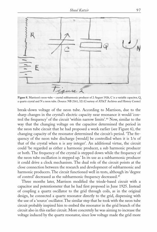
break-down voltage of the neon tube. According to Marrison, due to thesharp changes in the crystal’s electric capacity near resonance it would ‘con-trol the frequency’ of the circuit ‘within narrow limits’.44 Now, similar to theway that the changing voltage on the capacitor determined the period inthe neon tube circuit that he had proposed a week earlier (see Figure 6), thechanging capacity of the resonator determined the circuit’s period. ‘The fre-quency of the neon tube discharge [would] be controlled when it is 1/n ofthat of the crystal when n is any integer’. An additional virtue, the circuitcould ‘be regarded as either a harmonic producer, a sub harmonic produceror both. The frequency of the crystal is stepped down while the frequency ofthe neon tube oscillation is stepped up.’ In its use as a subharmonic producerit could drive a clock mechanism. The dual role of the circuit points at theclose connection between the research and development of subharmonic andharmonic producers. The circuit functioned well in tests, although its ‘degreeof control’ decreased as the subharmonic frequency decreased.45
Three months later, Marrison modified the triode-based circuit with acapacitor and potentiometer that he had first proposed in June 1925. Insteadof coupling a quartz oscillator to the grid through coils, as in the originaldesign, he connected a quartz resonator directly to the grid, dispensing withthe use of a ‘source’ oscillator. The similar step that he took with the neon tubecircuit probably inspired him to embed the resonator in the grid branch of thecircuit also in this earlier circuit. More concretely he was aiming to increase thevoltage induced by the quartz resonator, since low voltage made the grid more
97Shaul Katzir
Figure 8. Marrison’s neon-tube – crystal subharmonic producer of 2 August 1926, C is a variable capacitor, Qa quartz crystal and N a neon tube. (Source: NB 2161, 32) (Courtesy of AT&T Archives and History Center)
Katzir 25/4/17 15:41 Page 97

Invention and Development of Quartz Clock Technologies at AT&T
sensitive to fluctuations in the voltage due to other components of that branchof the circuit. These fluctuations were a probable source for the discharge thathad occurred in the middle of the crystal’s cycle before it had reached itsmaximal voltage. This premature discharge had lead to instability with largesubharmonics in the original design and was therefore undesirable. In themodified design, the working principle remained the same (see Figure 9).
Tests made by George Hecht from Marrison’s group showed that themethod allowed reaching the twenty-fifth subharmonic. Even though ‘thestability decrease[d] rapidly as we go to higher orders (lower frequencies)’,this was a clear advantage over the original design. As with other methods,one needed to tune the apparatus manually to reach a new subharmonic, butit kept each frequency without further human intervention. To improvestability Marrison suggested driving the quartz crystal with an independenttube circuit. His reasoning: ‘By this means the crystal is kept vibrating atlarger amplitudes than otherwise would be obtained and it has a greater con-trolling effect on the low frequency output.’46 Here, Marrison went back todividing the circuit into sub-circuits, a general tendency in his design,although in this case he did not return to a separate piezoelectric oscillatoruntil two months later, when he used a new method, which AT&T wouldadopt for its frequency standard.
The first quartz frequency standard and clockBy 27 January 1927, Marrison invented a new device, which he called ‘A Sub
98
Figure 9. Marrison’s subharmonic producer of November 1926. Here K is a capacitor and B a battery, whileE represents the EMF available by the potentiometer. The oscillating voltage from the crystal (Q ) sufficesto overcome the negative voltage on the grid (from a battery) only as the condenser (K) charges up, whichhappens ‘after the 1st, 2nd, 3rd (etc as desired) cycle of the crystal’. Once discharge begins, feedback coilskeep sufficiently high voltage on the grid to ensure an abrupt discharge of the condenser, as in the designfrom June 1925 (Figure 5). (Source: NB 2161, 62. (Courtesy of AT&T Archives and History Center)
Katzir 25/4/17 15:41 Page 98

99Shaul Katzir
Fig
ure
10.M
arri
son’
s ‘S
ub-M
ultip
le-F
requ
ency
Con
trol
Sys
tem
’of J
anua
ry 1
927.
(Sou
rce:
NB
216
1,73
) (C
ourt
esy
of A
T&
T A
rchi
ves
and
His
tory
Cen
ter)
Katzir 25/4/17 15:41 Page 99
Invention and Development of Quartz Clock Technologies at AT&T
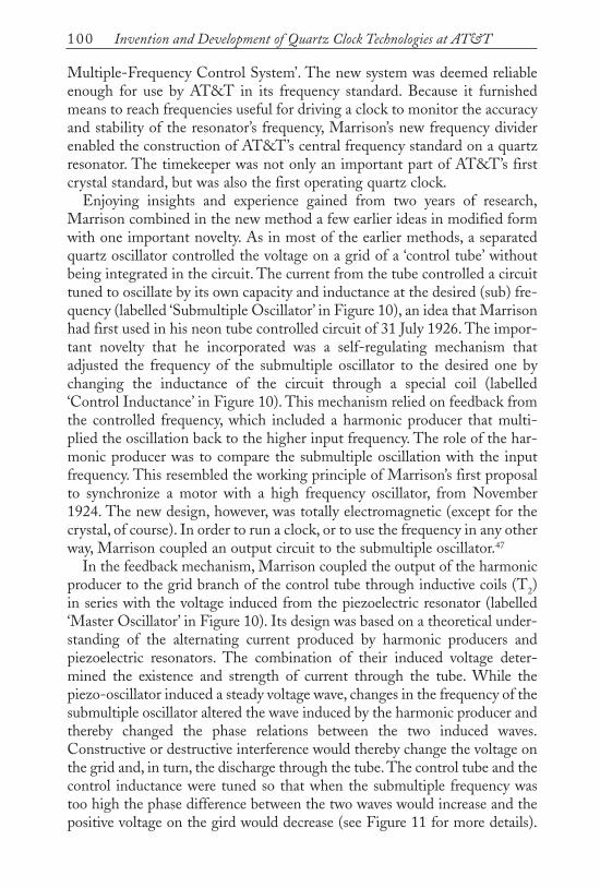
Multiple-Frequency Control System’. The new system was deemed reliableenough for use by AT&T in its frequency standard. Because it furnishedmeans to reach frequencies useful for driving a clock to monitor the accuracyand stability of the resonator’s frequency, Marrison’s new frequency dividerenabled the construction of AT&T’s central frequency standard on a quartzresonator. The timekeeper was not only an important part of AT&T’s firstcrystal standard, but was also the first operating quartz clock.
Enjoying insights and experience gained from two years of research,Marrison combined in the new method a few earlier ideas in modified formwith one important novelty. As in most of the earlier methods, a separatedquartz oscillator controlled the voltage on a grid of a ‘control tube’ withoutbeing integrated in the circuit. The current from the tube controlled a circuittuned to oscillate by its own capacity and inductance at the desired (sub) fre-quency (labelled ‘Submultiple Oscillator’ in Figure 10), an idea that Marrisonhad first used in his neon tube controlled circuit of 31 July 1926. The impor-tant novelty that he incorporated was a self-regulating mechanism thatadjusted the frequency of the submultiple oscillator to the desired one bychanging the inductance of the circuit through a special coil (labelled‘Control Inductance’ in Figure 10). This mechanism relied on feedback fromthe controlled frequency, which included a harmonic producer that multi-plied the oscillation back to the higher input frequency. The role of the har-monic producer was to compare the submultiple oscillation with the inputfrequency. This resembled the working principle of Marrison’s first proposalto synchronize a motor with a high frequency oscillator, from November1924. The new design, however, was totally electromagnetic (except for thecrystal, of course). In order to run a clock, or to use the frequency in any otherway, Marrison coupled an output circuit to the submultiple oscillator.47
In the feedback mechanism, Marrison coupled the output of the harmonicproducer to the grid branch of the control tube through inductive coils (T2)in series with the voltage induced from the piezoelectric resonator (labelled‘Master Oscillator’ in Figure 10). Its design was based on a theoretical under-standing of the alternating current produced by harmonic producers andpiezoelectric resonators. The combination of their induced voltage deter-mined the existence and strength of current through the tube. While thepiezo-oscillator induced a steady voltage wave, changes in the frequency of thesubmultiple oscillator altered the wave induced by the harmonic producer andthereby changed the phase relations between the two induced waves.Constructive or destructive interference would thereby change the voltage onthe grid and, in turn, the discharge through the tube. The control tube and thecontrol inductance were tuned so that when the submultiple frequency wastoo high the phase difference between the two waves would increase and thepositive voltage on the gird would decrease (see Figure 11 for more details).
100
Katzir 25/4/17 15:41 Page 100

Consequently, the average current in the tube and in the control inductancein that branch would also decrease, resulting in an increase in its inductanceand in the inductance of the submultiple oscillator which thereby lowered thefrequency back to its desired value. A decrease of the output frequency wouldcause a reverse process: raising the voltage on the grid, resulting in a lowerinductance in the submultiple oscillator and an increase in its frequency to the
101Shaul Katzir
Figure 11. The effect of the harmonic producer on the control tube current – a graphical presentation:The left figure (‘FIG 2’) shows the grid voltage (left side) and the resulting current on the triode (‘plate cur-rent’ – on the right side) under the influence of the voltage induced by the master (piezoelectric) oscillatoralone. In this case the maximal voltage on the grid branch of the control tube would suffice to produce asmall stable periodic current in the triode, as shown in the right side of the figure. The two other figures showthe effect of connecting the harmonic producer to the circuit when the frequency of the submultiple oscilla-tor is either faster (right figure) or slower than the subharmonic (lower figure). When the frequency of thesubmultiple oscillator increased, the phase of the electric wave produced by the harmonic producer advancedin relation to that of the master oscillator. As shown for an extreme case in the right figure (‘FIG 3’), in thatcase the two waves have destructive interference, which nullifies the current at the plate. Since the harmon-ic producer sends a wave only once every few cycles of the piezoelectric oscillator, the current would be zeroonly at these cycle and would keep its normal value at the other cycles, as in 21A at the figure (correspon-ding to 21 of the grid voltage on the left side). When the output frequency decreased, it would retard so asto approach the master oscillator phase (‘FIG 4’ at the bottom). Their constructive interference would lead toa higher voltage on the grid (23) resulting in a stronger current in the control tube, as shown on the rightside of the figure. When synchronized the two voltage waves would keep an in-between and constant phasedifference that maintained a constant current in the tube. (Source, Marrison, ‘Frequency-control system’)
Katzir 25/4/17 15:41 Page 101
Invention and Development of Quartz Clock Technologies at AT&T
desired value.48 The two therefore functioned as a feedback mechanism thatheld the output frequency stable with respect to the grid.
By means of an ingenious mechanism, Marrison ensured the self-regulation of the circuit. The control inductance consisted of a ring ofmagnetic core having two windings, one connected to the plate (anode) ofthe control tube, the other forming a part of the controlled oscillator. Thematerial at the core had a highly variable permeability, which meant thatthe magnetic field strength (H) of the magnet was not a linear functionof the external magnetic field (B), but rose faster with the increase of theexternal field (e.g. twice the external field induced more than twice the innerfield). A change in the magnetic field in one part of the control inductancesufficed to change the permeability and thereby the inductance of the whole.Thus, when the direct current in the control tube winding increased, it wouldinduce a stronger magnetic field (as current always does), which wouldincrease the inductance of the control inductance and, with that, the induct-ance of the submultiple oscillator, thereby decreasing its frequency. Adecrease in the current would lead to a reverse process.
The methods and practices of Bell Labs provided Marrison with manyof the resources he needed to devise this self-regulating circuit. A fewresearchers at that laboratory had already suggested exploiting the strongresponse of a core of variable permeability on the magnetic and electricbehavior of coils and circuits. Although different from its use in Marrison’sclock, such uses were suggestive for his search of circuits with a self-regulatingmechanism. In addition, in late 1922, Ralph V. L. Hartley, Horton’s directsupervisor, suggested a harmonic generator based on coupling two circuits bya common magnetic core with windings in each circuit. The high inner mag-netic permeability of the core blocked an electric voltage, except for shortintervals when the magnetic flux is changed. Hartley relied on a specificmaterial developed by Western Electric, dubbed ‘permalloy’, due to its veryhigh permeability relative to that of other ferromagnets. Starting from 1913,Gustaf Elmen from the research branch developed the alloy to provide highpermeability for the needs of high load in long telephone wires of the Bell sys-tem. Once the alloy was available, researchers at AT&T, such as Hartley, con-tinued searching for uses in other technical contexts. Their regular meetingsand other interactions provided knowledge about such resources and methodsfor their use. The size of AT&T and its comprehensive care for the full sys-tem of telecommunication were crucial for developing the alloy for use in onerealm (cables understood with the tool of electromagnetic fields) and later forits implementation in others (electronic system). Marrison himself hadalready employed permalloy coils before he suggested the subharmonic pro-ducer. In July 1925, he used such coils as a balance tilted by a current initiatedby speech in a ‘suppressed carrier system’. Apparently, Marrison’s own ideas of
102
Katzir 25/4/17 15:41 Page 102

using the control inductance in the subharmonic producer inspired at leastone additional researcher at Bell Labs, William A. Knoop, who used it tocouple a few circuits in a synchronization system, patented in 1928.49
Marrison’s new subharmonic producer performed very well. By October1927, Marrison and Horton had ‘found that the frequency of a given currentcan be controlled by a current of higher frequency with much greater stabilitythan by a current of lower frequency’.50 The inventor had already filed apatent in March.51 Interestingly, AT&T decided to patent Marrison’s earliersuggestions for subharmonic producers only after reaching the newer morestable method. Apparently only after frequency division had seemed prac-tical, did AT&T try to defend it against potential competition (althoughunsuccessfully).52 With their application in the patent office, the Marrisongroup continued to examine the different components of the crystal basedfrequency standard system and made further improvements. They found thatthe new subharmonic producer allowed them to produce frequencies in aratio of fifty to one, twice as much as attained earlier and probably withsteadier results. Although by using two dividers in series it would have beenfeasible to reach a frequency of one hundred hertz to drive a synchronousmotor, the group preferred dividing the frequency in two steps: one electronicand one mechanical. Their work therefore relied on proved devices from thetuning-fork clock even as these devices complicated the system.53
Improving the precision of the clockIn the summer of 1927, Marrison’s group installed at AT&T the first fre-quency and time standard based on a quartz resonator. A quartz clock was anintegral part of this system, ensuring its accuracy. The group could havestopped its development, since the system had attained the accuracy neededfor AT&T’s telecommunication techniques, yet the success of the standardencouraged the researchers at Bell Labs to carry out elaborate research aimedat the clock’s further improvement. One reason for their continued work wastheir expectation that the continuous increase in the useful radio range wouldlead to a demand for higher accuracy in frequency measurement and control.Still, it seems that the quest for higher precision gained its own momentum,and this pushed the group to pursue higher accuracy.
Marrison and other researchers at Bell Lab examined, reconsidered andsuggested improvement of the different ingredients of their frequencyand time standard: the crystals and their cuts, the mounting and gaps of thecrystal oscillator and its circuit, as well as the subharmonic producer, thesynchronous motor, the means of producing a wide range of frequencies fromthe resonator, and the method for comparing the quartz oscillator to anastronomical clock. Although not a direct interest of AT&T, metrology andmethods of keeping time in particular occupied an increasing place in
103Shaul Katzir
Katzir 25/4/17 15:41 Page 103

Invention and Development of Quartz Clock Technologies at AT&T
Marrison’s attention. The field was not new for him; he had participated intime measurements for their own sake at least since he had taken part in themeasurements of the 1925 solar eclipse.54 By April 1929, the quartz clockhad reached an error rate ‘in the order of 0.01 second a day [about 1 in 107]’.This was twice as accurate as the pendulum clock at the Bureau ofStandards. The most accurate contemporary clock based on the new Shorttfree pendulum mechanism, the culmination of two hundred and fifty yearsof pendulum horology, had an error between one-hundredth and one-thousandth a second a day.55 Although the quartz clock could not yet replacethe best pendulum clock, in 1930 Marrison suggested using it to displaysidereal and mean solar time for astronomical needs from the same time-keeping element, which one could not do with a pendulum clock.56
To reach and exceed the accuracy of the best pendulum clocks, Marrisonhad to improve the individual components of his quartz system. He deemedthe crystal itself to be ‘[b]y far the most important element in a crystal-controlled oscillator’ and dedicated much effort to improving its stability.Identifying the effects of changing temperature as the greatest single sourceof error in the quartz system, he worked in two directions. First, he tried toimprove the thermal regulators in the system (an endeavour continued fromtuning-fork standards). Second, he worked on reducing the sensitivity of thequartz resonator to temperature variations. In May 1927, Marrison made abreakthrough in the latter effort with an innovative cut of the quartz crystal.He reasoned that since ‘plates of quartz cut in the plane of the optic andelectric axes usually have positive temperature coefficients and . . . plates cutin the plane of the optic axis but perpendicular to an electric axis have negativecoefficients’ a cut between these directions, or a vibration that involve both,would have practically a zero coefficient. In order to get the effect he wanted,Marrison applied knowledge of physics concerning the elasticity of quartz andits dependence on temperature. The implementation of his idea, however,required further experimental research on the elasticity of quartz (the value ofthe temperature coefficient at angles to known cuts is not simply a functionof the values in those cuts) and also a practical search for appropriate anglesand shapes of the crystal cuts carved at the laboratory. Only experimentationshowed that rings ‘have a temperature coefficient lower than disks of the samediameter and thickness’ (see Figure 12). With these rings the researchersattained at room temperature a coefficient of ‘less than one part in a millionper degree C’. As a by-product, ‘the ring shape permit[ted] of an improvedmethod of mounting in which there is very little friction to the holder’.57
Marrison’s ability to use the results of previous and contemporaryresearchers points to the professionalization and specialization of science andtechnology in the twentieth century. His method of applying compensatingeffects, for example, resembles Wilhelm E. Weber’s development a century
104
Katzir 25/4/17 15:41 Page 104

earlier of reed pipes that keepconstant pitch under changingairflow. Weber had also studiedtwo opposite effects, in his casethe effect of the airflow on themetal reed and on the aircolumn within the pipe, andfound that they can neutralizeeach other. Whereas Marrisonbuilt on the work of otherresearchers, Weber had had tostudy much of the correspond-ing information about theacoustics of reeds and aircolumns himself.58
Bell Labs offered rich resources for designing and constructing the new cutof the quartz crystal that Marrison needed. Its facilities allowed cutting andpolishing the crystals in house, its manpower long research hours for extend-ing the empirical knowledge on which his idea lay, and for examining its prac-tical application. Moreover, he could use the results of another group withinBell Labs. Following Raymond Heising’s observation of a discontinuouschange of frequencies with the dimensions of crystal cuts, his assistantFrederick R. Lack examined the effect of specific directions of cuts andtemperature on the frequencies of crystal resonators. Heising suggested a spe-cial cut, different from Marrison’s, that exploited the observer phenomenon toreduce the crystal’s thermal coefficient to practically nil. Already in July 1927,Heising had filed a patent suggesting the use of two crystal cuts, one with apositive and one with a negative thermal coefficient ‘to reduce undesired vari-ations in the frequency of the controlled oscillator due to temperaturechanges’. Marrison began by examining the effect of two perpendicular pairsof electrodes in the same quartz plate, and only later found a direction thatcombines coefficients of opposite signs in one crystal cut. Heising, however,had been working, not on a better standard, but on components for radiotransmitters. Thermally stable crystal cuts were valuable both for such circuits,which lacked thermal control, and also valuable to attain the high accuracyrequired in AT&T’s frequency and time standard. Working at the same com-pany, Marrison and Heising easily exchanged knowledge and experienceabout the resonators, which advanced the research of both groups.59
Although the rich resources and specific needs of AT&T made Marrison’sdevelopment more likely, other researchers devised resonator rings too. A fewmonths earlier Erich Giebe and Adolf Scheibe at the German Physikalisch-Technische Reichanstalt (PTR) also devised a resonator ring. The German
105Shaul Katzir
Figure 12. Georges Hecht, Marrison’s assistant, finishingthe first set of ‘zero-temperature-coefficient’ quartz rings.(Courtesy of AT&T Archives and History Center)
Katzir 25/4/17 15:41 Page 105

Invention and Development of Quartz Clock Technologies at AT&T
researchers, however, were not looking for higher thermal stability. Instead,they wanted to obtain a wide range of frequencies from piezo-resonators,including relatively low ones (they reached 800Hz). They also sought toobserve their resonance in special electric discharge containers illuminated bythe strong vibration that they developed. In 1927, the German pair usedtorsional modes of vibrations, hitherto unexplored, and utilized quartz ringscut in the plane of their electric axes, which vividly showed their modesof vibration. While they utilized ring cuts similar in form and in someproperties to Marrison’s, they did not look for better thermal stability and theircut did not share the characteristics of Marrison’s cut in this aspect.60 UnlikeGiebe and Scheibe, another foreign researcher, David Dye of the BritishNational Physical Laboratory, did seek more stable piezoelectric resonators(although he was probably more concerned about the resonators’ mechanicalstability since he designed a mechanism for compensating for variation of fre-quency with temperature). Like Marrison, Dye found a solution in a quartzcrystal ring. In the mid-1920s, Dye too developed a frequency standard basedon quartz to replace the tuning fork standard. It is not clear, however, when hebegin using a quartz ring for his standard. Moreover, Dye cut his crystal per-pendicular to its electric axes, i.e. in perpendicular to Marrison’s cut.61
Ironically, following his scrutiny of the frequency standard system,Marrison replaced the component of his system that had initially enabled theconstruction of an operating quartz clock: the subharmonic producer basedon controlled inductance. Initially content with the performance of the sub-harmonic producer, by April 1928, he judged that it has ‘not been as good asdesired’ and suggested improvements in the control circuit, without alteringits basic principles. Although Marrison expressed satisfaction with theimproved design, sometime during the following year he replaced it too witha circuit that worked on different principles. Originally, Marrison’s mainstrategy was to construct a circuit with a stable but adjustable internal fre-quency, and to limit its oscillations to a subharmonic of a controlling circuit,similar to the harmonic producer controlled by the tuning-fork circuit. In hisnew design he dispensed with the idea of a stable submultiple circuit andsettled for an inherently unstable tube circuit oscillator, i.e. a circuit able tovibrate at a large range of frequencies. Such a circuit would oscillate at a fre-quency ‘which is a small multiple or submultiple of ’ the control frequency.62
In replacing the subharmonic generator in his system, Marrison adoptedan approach that originated outside of Bell Labs. Researchers at MIT,Philips, the Italian Navy, the National Physical Laboratory and the Tokyoelectro-technical institute all developed alternative frequency dividers. Oneof them, Balthasar van der Pol, provided a theoretical account for thetendency of inherently unstable oscillators to vibrate at a harmonic or sub-harmonic of a source voltage.63 These developments by other researchers
106
Katzir 25/4/17 15:41 Page 106

helped Marrison replace his rather complex, if ingenious, submultiple circuitwith a simpler circuit. Despite the replacement of a key ingredient in his fre-quency and time standard with a component that originated outside ofAT&T, Bell Labs maintained its lead in quartz time standards for a fewyears.64 With the exception of the quartz resonator itself, the system as awhole was more important than the specific details of its single components.Thus, the quartz clock required more than the invention of one component(like the subharmonic generator). More than that, it required the develop-ment of the way they were assembled. Notwithstanding Marrison’s primerole, this system originated from a network of physicists, engineers andinventors, both inside and outside the Bell system.
CONCLUSION
Inventing the quartz clock system, Marrison followed a twisted road. Table1 summarizes the devices that he suggested for a time and frequencystandard, their sources and the relationships among them. Quite a few of thedevices that he suggested for dividing the frequency of piezoelectricresonators did not evolve from their immediate predecessor. Instead, headopted ideas from the tuning-fork standard, in use by AT&T at the time,and from other systems. Others of his devices clearly were evolved fromprevious ones. Yet sometimes the processes of modification and elaborationled to completely new designs. For example, the circuits that Marrisondevised during July and August of 1926 began with the utilization of aseparate piezo-oscillator and ended with embedding a piezo-resonatorwithin a main neon tube circuit. At other times, Marrison returned to anolder design in a modified form. For example, in November 1926, he con-sidered a different way of connecting the piezo-resonator to the triode, in acircuit otherwise equivalent to the one he had suggested in June 1925.Marrison’s methods for reducing frequencies can be grouped into twoapproaches: mechanical and electronic. He began with the former and turnedto the latter in March 1925. Still, a month later he returned to a mechanicalmethod. Although not ultimately used, his earlier methods provided ideasthat he incorporated in later circuits. For example, the ‘inductance control’method, which he used in the 1927 quartz clock, shared a logical structurewith his first suggestion from November 1924. In both cases Marrison re-multiplied the lower output frequency and compared it with that of thepiezoelectric oscillator. Similarly, although Marrison’s quartz clock was notused by others, his ideas are worth recording in detail because they revealhow industrial inventors worked, using the resources of the laboratories theywork in a proceeding along many different tracks in pursuit of a given goal.
Oftentimes novelty emerges from implementing known ideas in a new
107Shaul Katzir
Katzir 25/4/17 15:41 Page 107

Invention and Development of Quartz Clock Technologies at AT&T108Ta
ble
1.M
arris
on’s
sug
gest
ions
for r
each
ing
a kn
own
low
er fr
eque
ncy
from
that
of a
qua
rtz re
sona
tor,
Nove
mbe
r 192
4 –
Janu
ary
1927
Date
Ki
ndOp
erat
ing
prin
cipl
esNo
.of
High
est
Poss
ible
use
sPr
edec
esso
rBa
ckgr
ound
kno
wle
dge2
frequ
enci
esdi
visi
on o
f m
etho
dob
tain
ed1
frequ
ency
Nov.
24Sy
nchr
onou
sM
echa
nica
l + m
odul
ator
110
1Cl
ock3
Cloc
k m
echa
nism
,har
mon
ic
mot
orpr
oduc
er &
mod
ulat
or o
f tu
ning
fork
sta
ndar
dM
ar.2
5Tw
o pi
ezo-
Mod
ulat
or1
Abou
t 10
Cloc
kNo
v.24
osci
llato
rsJu
ne 2
5Su
bhar
mon
ic
Cont
rolle
d tu
be-c
apac
itor
34
Atta
inin
g lo
wer
Ha
rmon
ic p
rodu
cer (
as
prod
ucer
circ
uit
frequ
enci
esin
the
tuni
ng fo
rk s
tand
ard)
July
25
Two
sync
hron
ous
Mec
hani
cal +
mod
ulat
or1
Abou
t 20
Cloc
kNo
v.24
m
otor
s23
Jul
y 26
Subh
arm
onic
Co
ntro
lled
tube
-cap
acito
r Un
know
n Un
know
nCl
ock
& lo
wer
Ju
ne 2
5 Ge
nera
l use
of n
eon
tube
pr
oduc
erci
rcui
t with
neo
n tu
befre
quen
cies
in e
lect
roni
cs31
Jul
y 26
Subh
arm
onic
Co
ntro
lled
tube
-cap
acito
r Un
know
nUn
know
nCl
ock
& lo
wer
23
Jul
y 26
prod
ucer
with
neo
n tu
be a
nd it
s fre
quen
cies
own
LC c
ircui
t2
Aug
26Su
bhar
mon
ic
Piez
o-re
sona
tor –
neo
n tu
beUn
know
nUn
know
nCl
ock
& lo
wer
31
Jul
y 26
Expe
rienc
e w
ith p
iezo
-pr
oduc
erfre
quen
cies
elec
tric
reso
nato
rsNo
v.26
Subh
arm
onic
Pi
ezo-
reso
nato
r con
nect
ed to
24
25Cl
ock
& lo
wer
Ju
ne 2
5pr
oduc
er
cont
rolle
d tu
befre
quen
cies
Jan.
27Su
bmul
tiple
M
agne
tic c
ontro
l 49
50
Cloc
k &
low
er
Jun.
25; N
ov.2
4;
Use
of v
aria
ble
indu
ctan
ce
osci
llato
rin
duct
ance
,fee
dbac
kfre
quen
cies
31 J
ul 2
6 at
Bel
l sys
tem
Note
s1
Abov
e th
e in
put f
requ
ency
/ies
2Be
yond
the
know
ledg
e th
at w
as u
sed
in th
e pr
edec
esso
r met
hods
.3
That
is, t
he m
etho
d al
low
ed d
rivin
g a
cloc
k m
echa
nism
.
Katzir 25/4/17 15:41 Page 108

context. Many of Marrison’s innovations followed from variations on previoustechniques and adaptations of methods and procedures from one realm (e.g.tuning-forks) to another (e.g. quartz resonators), or from one device(e.g. piezo-resonator connected to a neon tube in August 1926) to another (e.g.piezo-resonator connected to a triode in November). Replacing the tuning-fork with the quartz resonator required considerable changes to AT&T’sfrequency standard, but Marrison’s group continued to use parts from thepreceding standard system (e.g. the clock mechanism), and to combine ideasand techniques from other parts of that system. For example, in November1924, Marrison employed the technique of driving a synchronous motor byelectric oscillations, a technique previously used with the tuning-fork standard.Replacing this mechanical method with an electronic one, a few months laterhe devised a subharmonic producer in analogue to the harmonic producer usedwith the older standard. As he had done in its predecessor, he controlled thefrequency of a target circuit, tuned to oscillate at the desired frequency, by aperiodic physical influence from the source circuit. In these and other cases,novelty resulted from combining known and usually common components andmodifying their specific properties. Though known, the components that heused were state-of-the-art devices available at the corporate laboratory, fromthe common triodes, through the less ordinary neon tubes, to the relatively newpiezoelectric resonators and oscillators and the uncommon coil with a highpermeability core. Their combinations resulted in novel devices.
The new way to cut a quartz crystal that he developed, the high point (butnot the end) of the research on stabilizing the crystal resonator, exemplifiesMarrison’s debt to theoretical knowledge. Although he contributed to theknowledge of elasticity by empirically finding the exact direction of a zerothermal coefficient in a quartz crystal, fostering science was only an atypicalby-product of his group’s research. The members of Horton’s group at Bell hadlittle freedom to pursue more general, in this sense scientific, questions that didnot relate directly to their immediate technological aims. They were, however,well-versed in the current scientific and engineering literature. In addition,they learnt about new developments and approaches, sometimes before theywere published, through direct exchange with researchers, outside of Bell Labs,like Cady. While outside developments were discussed within Bell Labs, moreimportant was the circulation of ideas in use at AT&T, like those of combin-ing crystal cuts in different manners to reduce the variations of their frequencywith temperature, and the use of permalloy in coils to control electric circuits.The laboratory’s own large staff allowed its researchers to experimentallyexplore a sizeable number of their ideas. Like his colleagues, Marrison also hadrich material resources at his disposal. These included, among other things,state of the art electronic tubes,65 the means to cut and polish crystals at thelaboratory, and the permalloy for his coils. The general strategy of combining
109Shaul Katzir
Katzir 25/4/17 15:41 Page 109

Invention and Development of Quartz Clock Technologies at AT&T
and varying extent techniques and components was well-known and used byinventors. Yet the facilities of the modern corporation made it particularlypotent. The rich intellectual and material resources allowed the modern cor-porate inventor to employ varied devices and methods, to modify them tospecific needs, combine them and examine the performances both of the indi-vidual components and of the composite devices. While Marrison, Horton andother researchers at Bell Labs showed ingenuity, these resources were crucialfor their inventions and their success in constructing the first quartz clock.
ACKNOWLEDGEMENTS
I thank Jaume Navarro for his comments an earlier version of this article, theanonymous referees for their suggestions, the editor of ICON for her helpfulwork, and George Kupczack for his help at AT&T archives. I am grateful tothe institutions that supported my research on and writing of this article asa Humboldt fellow at the Max Planck Institute for the history of science, anda Marie Curie Fellow of the Gerda Henkel Foundation (M4HUMAN) atTel Aviv University.
NOTES
1 Thomas P. Hughes, American Genesis: A Century of Invention and Technological Enthusiasm,1870–1970 (New York: Viking, 1989), 138–9.
2 Hughes, American Genesis, 66–71 (independents’ choice of problems).3 E.g., Hugh G.J. Aitken, The Continuous Wave: Technology and American Radio, 1900–1932
(Princeton, N.J.: Princeton University Press, 1985), 188–189, 228; Ian Wills, ‘InstrumentalizingFailure: Edison’s Invention of the Carbon Microphone’, Annals of Science, 64 (2007): 383–409.
4 On the history of tuning-fork standards, see, Shaul Katzir, ‘Frequency and Time Standards fromAcoustic to Radio: The First Electronic Clock’, Lara Huber and Oliver Schlaudt (eds)Standardization in Measurement: Philosophical, Historical and Sociological Issues (London: Pickeringand Chatto, 2015), 111–124.
5 For a comprehensive discussion of the technological and societal aims and problems that led to thedevelopment of quartz clock technologies by the various groups that worked towards them in theacademy, industry and state laboratories, and of the research carried by those groups, see ShaulKatzir, ‘Pursuing frequency standards and control: the invention of quartz clock technologies’,Annals of Science, 73 (2016): 1–39. Here I refer only briefly to the reasons that directed AT&T’sresearchers to the specific technological problems that they examined. Other histories of thedevelopments in AT&T do not suggest the close analysis of the invention and development processoffered here. See Carlene E. Stephens, ‘Reinventing Accuracy: The First Quartz Clock of 1927’, inDie Quarzrevolution: 75 Jahre Quarzuhr in Deutschland 1932–2007, ed. Johannes Graf (Furtwangen:Dt. Uhrenmuseum, 2008), 12–23 and the fair reconstruction by the chief protagonist: Warren A.Marrison, ‘The Evolution of the Quartz Crystal Clock’, The Bell System Technical Journal, 27 (1948):510–588.
6 For an elaborated discussion of the consequences of the quartz clock technologies see Shaul Katzir,‘Time Standards for the Twentieth Century: Telecommunication, Physics and the Quartz Clock’,The Journal of Modern History, 89 (2017): 119–150.
7 Joseph W. Horton, Norman H. Ricker, and Warren A. Marrison, ‘Frequency Measurement in
110
Katzir 25/4/17 15:41 Page 110

Electrical Communication’, Transactions of the American Institute of Electrical Engineers 42(1923): 730.
8 Aitken, The Continuous Wave: Technology and American Radio, 1900–1932; Sungook Hong, Wireless:From Marconi’s Black Box to the Audion (Cambridge, MA: MIT Press, 2001), 155–189.
9 Horton, Ricker, and Marrison, ‘Frequency Measurement in Electrical Communication’, quote onp. 730; Marrison NB 1112-2, p. 38 (29 May 1922), which mentions also earlier work, Riker NB1097-2 ( June 1921–December 1922). (Unless otherwise indicated, unpublished material is takenfrom AT&T Archives and History Center, Warren, NJ. The abbreviation NB throughout thesenotes stands for Notebook.)
10 The unit was also called the Research Department.11 Joseph Warren Horton, Excursions in the domain of physics, a typed manuscript, 1965 at the
American Institute of Physics library, quotations on 3, 5; Obituary in IEEE Spectrum, 4 (1967):38–39; Brittain, James E., ‘Joseph Warren Horton’, Proceedings of the IEEE, 82.4 (1994) (http://ieee.cincinnati.fuse.net/reiman/11_2006.html accessed 25 February 13). For more details see Katzir,‘Pursuing Frequency Standards’, 7.
12 Norman Ricker Autobiography, typed manuscript at ‘Norman Hurd Ricker Papers’, in WoodsonResearch Center, Foundren Library, Rice University (23/206), 36–40; ‘Chart of Western ElectricCompany Research Department, Dec. 1922’, (14/142); W. R. Topham, ‘Warren Marrison –Pioneer of the Quartz Revolution’, NAWCC [The National Association of Watch and Clock CollectorsBulletin], April 1989, 126–134. Marrison’s first dated notebook entry in AT&T is from June 1920;Marrison’s ‘record card’ at Harvard University Archives. I thank its staff for informing me about thecontent of this file.
13 NB 111-2, began by Davidsson (October 1921–March 1922) continued by Marrison from 29 May1922. Leonard S. Reich, The Making of American Industrial Research: Science and Business at GE andBell, 1876–1926 (Cambridge: Cambridge University Press, 1985), 202–04. Horton, Ricker, andMarrison, ‘Frequency Measurement in Electrical Communication’.
14 Joseph W. Horton, ‘Harmonic generator system’ US patent 1519619, filed 23 December 1920,patented 1924, quotations on 1; E.H. Colpitts and O.B. Blackwell, ‘Carrier Current Telephony andTelegraphy’, Transactions of the American Institute of Electrical Engineers, 40 ( January 1921):205–300.
15 Marrison NB 1112-2, 38–39 (29.5.22), Horton, Ricker, and Marrison, ‘Frequency Measurement inElectrical Communication’. One could attain a specific frequency also directly by multiplying theoriginal oscillation by the desired number. This was the strategy of David Dye at the BritishNational Physical Laboratory, using one or two multivibrators. Horton’s group divided the processinto two separate steps first generating known high harmonics and then combining them to reachany specific frequency. Horton, Ricker and Marrison claimed that this division leads to higheraccuracy and fewer mistakes with higher frequencies since direct multiplication of high order isprone to lead to a non-intended harmonics (ibid., p. 741). David Dye, ‘The Valve-MaintainedTuning-Fork as a Precision Time-Standard’, Proceedings of the Royal Society of London. Series A,Containing Papers of a Mathematical and Physical Character, 103 (1923): 240–260.
16 E.g. David Pantalony, Altered Sensations: Rudolph Koenig’s Acoustical Workshop in Nineteenth-CenturyParis (Dordrecht: Springer, 2009), 102–104.
17 However, the group did examine the effect of temperature on the frequency of its own tuning-fork,finding a coefficient of 0.0109 per cent per degree C. Joseph W. Horton and W.A. Marrison,‘Precision Determination of Frequency’, Proceedings of the IRE, 16.2 (1928): 137–154, 139–140.
18 Horton, Ricker, and Marrison, ‘Frequency Measurement in Electrical Communication’.19 The connection of the tuning-fork to the multivibrator was mention in the Annual Report of the
National Physical Laboratory for the Year 1919 (Teddington: National Physical Laboratory, 1920),51, and Annual Report of the National Physical Laboratory (Teddington: National PhysicalLaboratory, 1922), 71.
20 To understand the working principles of the method we can ignore the third circuit in the figure(of L2 and C2).
111Shaul Katzir
Katzir 25/4/17 15:41 Page 111

Invention and Development of Quartz Clock Technologies at AT&T
21 Horton, Ricker, and Marrison, ‘Frequency Measurement in Electrical Communication’, 739–741;Ricker NB 1097-2, especially 41–42 (22 July 1922); Joseph W. Horton, ‘Source of Waves ofConstant Frequency’, patent, US1560056, filled 1 May 1923 (issued November 1925).
22 Horton, Ricker and Marrison, ‘Frequency Measurement in Electrical Communication’, 731.23 Marrison NB 1112-2, 38–41; Horton, Ricker and Marrison, ‘Frequency Measurement in Electrical
Communication’, 734–736; a report of R.V.L. Hartley to Harold Arnold 28 November 1922 (loc79 10 01 14, in Arnold’s papers), Warren A. Marrison, ‘The Evolution of the Quartz Crystal Clock’,The Bell System Technical Journal, 27 (1948): 510–588, 528; Marrison (NB 1444, 42, 149–153).
The synchronous motor was based on the phonic wheel, a well-known instrument at the time,consisting of a cogwheel whose centre is an electromagnet and its circumference is made from softiron. When the iron-circumference moves near a tuning-fork, itself made from a magnetized metal,it becomes magnetic. Consequently, magnetic forces on the teeth, from the electromagnet and thetuning-fork the teeth adjust the wheel to rotate in phase with the tuning-fork. Due to a few tech-nical problems with the motor the group devised a few models eventually settled on a 100-cyclemotor geared directly to the clock mechanism.
24 On these methods and the relations between AT&T’s clock and earlier tuning-fork based frequencystandards and clocks see Katzir, ‘Time Standards from Acoustic to Radio’, 116–120.
25 Horton, Ricker, and Marrison, ‘Frequency Measurement in Electrical Communication’, 736.26 Horton and Marrison, ‘Precision Determination of Frequency’, first quote 141. Marrison, ‘The
Evolution of the Quartz Crystal Clock’, 528–530; United States National Bureau of Standards,Standards Yearbook (U.S. Govt. Print. Off., 1927), 44. D.W.Dye and L. Essen, ‘The ValveMaintained Tuning-fork as a Primary Standard of Frequency’, Proceedings of the Royal Society ofLondon. Series A, 143 (1934): 306.
27 The high number of ‘suggestions’ recorded in the laboratory’s notebooks and the diversity of theirsubjects, even within the same notebook, testify to the practice of examining alternative means alsoto methods in use. See, for example, notebooks of Ricker and Marrison.
28 Davidson and Marrison, NB 1112-1, especially 38 (Marrison, 29 May 1922 – a report about earlierwork), Ricker NB 1097-2, especially 21 (26 July – rod) 23, 30 (26 August, 2 December 1921 – bar),Marrison, NB 1444, passim 55 (12 November 1924 – bar), 73–78 (8 December 1924 – torsionaloscillations). On quartz see also the list of suggestions in NB 2161 and NB 2162. AT&T archivehas not kept Horton’s notebook, so the discussion here relies more on Marrison’s research. His note-books, however, mention also work of the group in general without assigning a particular author.
29 Warren A. Marrison, ‘Some Facts about Frequency Measurement’, Bell Laboratories Record, 6(1928): 385. Lloyd Espenschied, ‘The Origin and Development of Radiotelephony’, Proceedings ofthe Institute of Radio Engineers, 25, (1937): 1101–1123.
30 To reach the new frequency range, by 1928 Horton group added a cathode ray oscillograph, whichallowed higher multiplications of the input frequency. Still, piezoelectric resonators suggested asimpler method to attain very high frequencies. Horton and Marrison, ‘Precision Determination ofFrequency’, 142.
31 Shaul Katzir, ‘From Ultrasonic to Frequency Standards: Walter Cady’s Discovery of the SharpResonance of Crystals’, Archive for History of Exact Sciences, 62 (2008): 469–487; idem, ‘War andPeacetime Research on the Road to Crystal Frequency Control’, Technology and Culture, 51 (2010):99–125.
32 Ibid., 117–120.33 Marrison, NB 1112-1, 38 (29 May 1922).34 Katzir, ‘Pursuing Frequency Standards’, especially 13–14.35 Marrison NB 1444, 55 (15 November 1924).36 NB 1444, 177 (20 July 1925). In his history of the quartz clock Marrison implies that his November
1924 suggestion was a first attempt ‘for a combined time and frequency standard’, which did notbecame a basis for a clock only because a simpler method was proposed. Marrison, ‘The Evolutionof the Quartz Crystal Clock’, 537–539. The contemporary evidence, however, points to the use ofthe clock as ‘a convenient method of checking the frequency over long intervals’ (NB 1444, 177),rather than an attempt to establish a time standard.
112
Katzir 25/4/17 15:41 Page 112

37 On the use of this range for multiplex at the Bell system see E.H. Colpitts and O.B. Blackwell,‘Carrier Current Telephony and Telegraphy’, Transactions of The American Institute of ElectricalEngineers, 40 (1921): 205–300; T.E. Shea and C.E. Lane, ‘Telephone Transmission Networks Typesand Problems of Design’, Transactions of The American Institute of Electrical Engineers, 48 (1929):1031–1044.
38 See Marrison’s notebooks for efforts to extend the range of quartz frequencies, and for attempts touse the same oscillator for a few frequencies. For an explicit mention of control at these frequenciessee Hecht in Marrison NB 2162, 169 (15 November 1926).
39 NB 1444, 129 (19 March 1925).40 With a thought to future patent claims Marrison referred to the source in a general way. Yet from
the context it is clear that the radio frequency source in his mind (and the one actually used in itstests) was a piezo-oscillator.
41 Marrison NB 1444, 168–169 (25 June 1925), Marrison, ‘Subharmonic frequency producer’, USpatent 1733614, filed 20.8.27. Unlike the source frequency the resulted alternating current is notsinusoidal (i.e. symmetric in time and in positive and negative current). Yet this was not an obstaclefor using the output oscillation as an input for further manipulations.
42 Marrison NB 2161, 28 (23 July 1926). Marrison wrote that ‘[s]everal methods are possible for’ oper-ating a synchronous motor and presented a ‘typical method’ for that end. Unfortunately, the AT&Tarchives do not possess records of the team’s crystal research from October 1925 to April 1926.
43 NB 2161, 28 (23 to 31 July 1926).44 NB 2161, 28 (signed 31 July 1926) and 32 (2 August 1926).45 NB 2161, 34 (5 August 1926). Since the resonator possesses significance capacity, in checking the
device Marrison dispensed with the independent capacitor. To allow reaching different values fromthe same circuit he used a variable resistor.
46 NB 2161, 62 (10 November 1926), 63 (17 November 1926), NB 2162, 169–171 (15 November1926).
47 NB 2161, 73–74 (27 January 1927).48 In the initial suggestion the voltage from the piezo-oscillator alone was insufficient to overcome the
negative potential of the battery Ec, as was the case in Marrison’s earlier suggestions. In the operat-ing version, which the group developed in the coming weeks, the circuit was tuned to allow currentat the peeks of the oscillator’s positive voltage, and the voltage from the harmonic oscillator was usedonly to vary the value of the average current through the tube; Warren A. Marrison, ‘FrequencyControl System’, US patent 1,788,533, filed 28.3.1927.
49 R.V.L. Hartley, NB 1060-1101-3 (30 December 1922); quotation from Marrison NB 1444, 175(10 July 1925); S Millman, ed., A History of Engineering and Science in the Bell System: PhysicalSciences (1925–1980) (New York: Bell Telephone Laboratories, 1983), 801–808; William A. Knoop,‘Synchronizing system’, US1747248, filed 10 February 1928, patented 18 February 1930.Apparently uses of variations of magnetic permeability were rare outside AT&T, for an exceptionsee Quincy A. Brackert, ‘Receiving system’, US1567566, filed 12 April 1921. Brackert worked atWestinghouse.
50 They imply that this conclusion had been reached before the invention of the circuits described intheir paper, i.e. before March 1927, but I haven’t found an earlier indication for such a strong claim;Horton and Marrison, ‘Precision Determination of Frequency’, 143.
51 Marrison, ‘Frequency Control System’. US patent 1,788,533. The patent included a few improve-ments on the suggestion from January.
52 On the development of alternative frequency dividers, see Katzir ‘Pursuing Frequency Standards’.53 Horton and Marrison, ‘Precision Determination of Frequency’, 148–149, NB 2162, 188, 189,
(31.3.1927, 8.4.1927, entries by J.L. Whittaker, a researcher at Marrison’s group).54 Marrison, ‘The Evolution of the Quartz Crystal Clock’, 528–530; Marrison NB 1444, 97–105,
(24 January 1925).55 Steven J. Dick, Sky and Ocean Joined: The U.S. Naval Observatory 1830–2000 (Cambridge
University Press, 2002) Chapter 11, especially 461–462.
113Shaul Katzir
Katzir 25/4/17 15:41 Page 113

Invention and Development of Quartz Clock Technologies at AT&T
56 Marrison, ‘A High Precision Standard of Frequency’, 1112; Warren A. Marrison, ‘The CrystalClock’, Proceedings of the National Academy of Sciences of the United States of America, 16 (1930):496–507.
57 To increase accuracy, the crystal resonator was still put in a temperature control chamber. Marrison,‘A High Precision Standard of Frequency’, quotations on 1103, 1104, 1106; Fredrick R. Lack,‘Observations on Modes of Vibration and Temperature Coefficients of Quartz Crystal Plates’,Proceedings of the Institute of Radio Engineers, 17 (1929): 1123–1141. Marrison NB 2161, forexample 92–93 (10 May 1927): ‘Temperature Coefficient of Quartz Control’ (first appearance ofthe oblique cut idea), 99, 126, 129, 130, 147 (24 May, 25 August, 3 October, 4 October, 16December 1927), also in Marrison’s next ‘Suggestion Book’, NB 2658, which he opened on 14 June1928.
58 Myles W. Jackson, Harmonious triads: Physicists, musicians, and instrument makers in nineteenth-century Germany (Cambridge, Mass.; London: MIT, 2008), 114–118. Weber’s technologicalendeavour was part of more general research on the phenomenon under question – acoustics.Marrison, on the other hand, concentrated on the use of piezoelectricity (and earlier elasticity offorks) for precision measurements.
59 Marrison recalled his collaboration with Heising concerning ‘Crystals and Quartz Clock’, Marrisonto Baker 12 July 1977. In 1929, he and Lack referred to the papers of each other, which appearedin the same issue (above fn. 54). Raymond A. Heising, ‘Crystal-controlled Oscillator’, US patent1840580, filed 25 July 1927. According to their collaborator on quartz crystals, Warren P. Mason,Marrison preceded Heising in suggesting a special cut from the same crystal (‘Low TemperatureCoefficient Quartz Crystals’, Bell System Technical Journal, 19 (1940): 74–93, on 75). ‘Raymond A.Heising – Member Board of Direction, 1929’, Proceedings of the Institute of Radio Engineers, 17(1929): 6; ‘Raymond A. Heising: Board of Directors-1947’, ibid. (1947), 1179; Lloyd Espenschied,‘R. A. Heising, former President of IRE, dies at 76’, Spectrum, IEEE, 2 (1965): 222.
60 By early 1927 Giebe and Scheibe concluded that ‘the influence of temperature is utmost small[äußerst gering]’, (‘Die Tätigkeit der Physikalisch-Technischen Reichsanstalt im Jahre 1926’,Zeitschrift für Instrumentakunde, 47 (1927): 269–294, 275; E. Giebe, ‘Leuchtende piezoelektrischeResonatoren als Hochfrequenznormale’, Zeitschrift für technische Physik, 7 (1926): 235. E. Giebe undA. Scheibe, ‘Piezoelektrische Kristalle als Frequenznormale’, Elektrische Nachrichten-Technik, 5(1928): 65–82 (received in November 1927).
61 L. Essen, ‘The Dye Quartz Ring Oscillator as a Standard of Frequency and Time’, Proceedings ofthe Royal Society of London A: Mathematical, Physical and Engineering Sciences, 155 (1936): 498–519;Walter G. Cady, Piezoelectricity: An Introduction to the Theory and Applications of ElectromechanicalPhenomena in Crystals (New York: McGraw-Hill, 1946), 77; Ray Essen, ‘Greenwich Time: FromPendulum to Quartz 1’, Horological Journal, 154 (2012): 198–201.
62 Quotations from NB 2161, 184 (23 April 1928) Marrison, ‘A High Precision Standard ofFrequency’, 1112.
63 On these frequency dividers and van der Pol’s work see Katzir, ‘Pursuing Frequency Standards,18–35’, Balthasar van der Pol, ‘On “relaxation-Oscillations”’, Philosophical Magazine, 2 (1926):978–992.
64 Marrison, ‘The Crystal Clock’. Still, in the early 1930s the national laboratories of Britain andGermany, which had a stronger interest in accuracy, exceeded the precision of AT&T’s clock.
65 Cady, for example had to borrow tubes from Western Electric, e.g. H. D. Arnold to B. W. Kendall,13 Febuary 1918, Arnold to Cady 5 June 1919, AT&T Archive (Loc. 79 10 01 03).
114
Katzir 25/4/17 15:41 Page 114