Karl S Bogha IEEE Std 80 - 2013 (Guide for Safety of AC ... · Karl S Bogha IEEE Std 80 - 2013...
20
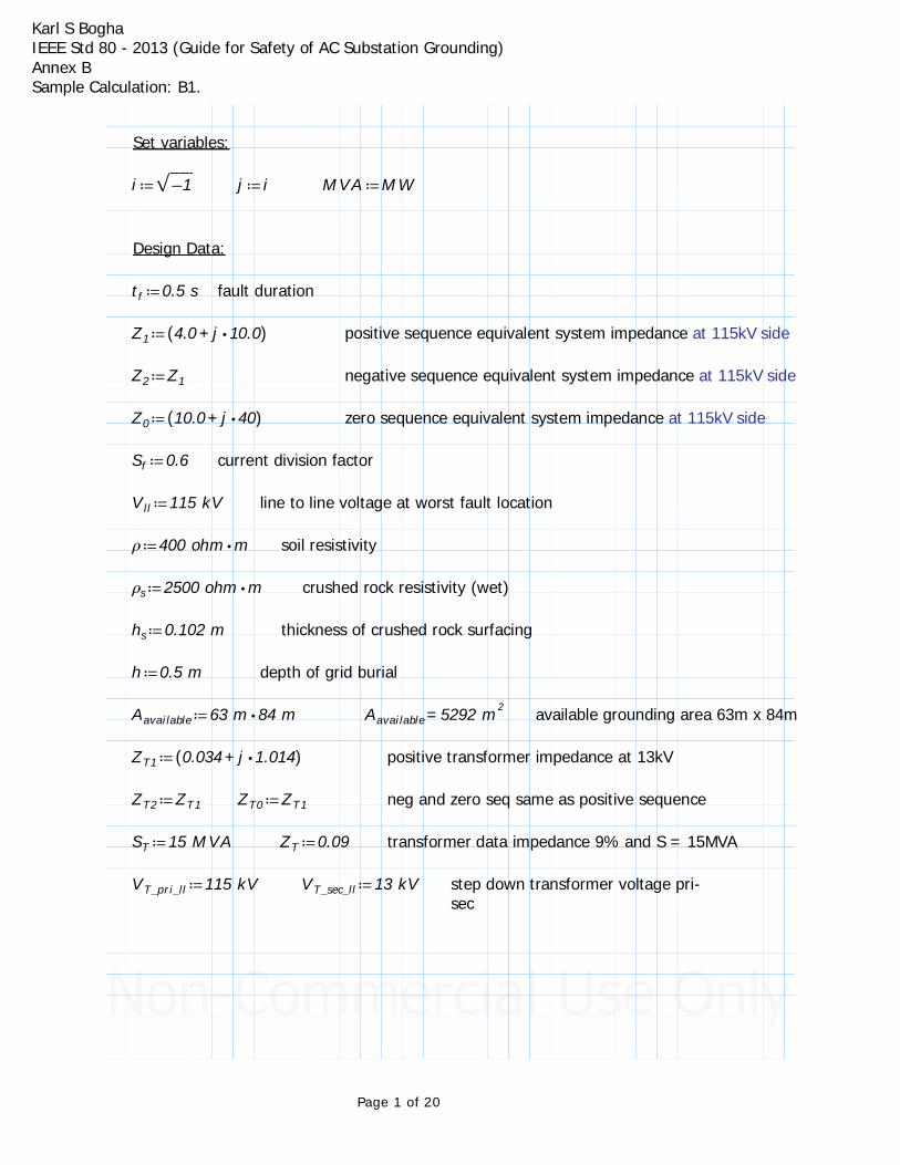
Karl S Bogha IEEE Std 80 - 2013 (Guide for Safety of AC Substation Grounding) Annex B Sample Calculation: B1. Set variables: i Ơ Ơ Ơ ˕ 1 j i MVA MW Design Data: t f 0.5 s fault duration Z 1 ( ( + 4.0 Έ j 10.0) ) positive sequence equivalent system impedance at 115kV side Z 2 Z 1 negative sequence equivalent system impedance at 115kV side Z 0 ( ( + 10.0 Έ j 40) ) zero sequence equivalent system impedance at 115kV side S f 0.6 current division factor V ll 115 kV line to line voltage at worst fault location Ņ Έ 400 ohm m soil resistivity Ņ s Έ 2500 ohm m crushed rock resistivity (wet) h s 0.102 m thickness of crushed rock surfacing h 0.5 m depth of grid burial A available Έ 63 m 84 m = A available 5292 m 2 available grounding area 63m x 84m Z T1 ( ( + 0.034 Έ j 1.014) ) positive transformer impedance at 13kV Z T2 Z T1 Z T0 Z T1 neg and zero seq same as positive sequence S T 15 MVA Z T 0.09 transformer data impedance 9% and S = 15MVA V T_pri_ll 115 kV V T_sec_ll 13 kV step down transformer voltage pri- sec Page 1 of 20
Transcript of Karl S Bogha IEEE Std 80 - 2013 (Guide for Safety of AC ... · Karl S Bogha IEEE Std 80 - 2013...
Karl S BoghaIEEE Std 80 - 2013 (Guide for Safety of AC Substation Grounding)Annex B Sample Calculation: B1.
Set variables:
≔i ‾‾‾−1 ≔j i ≔MVA MW
Design Data:
≔tf 0.5 s fault duration
≔Z1 (( +4.0 ⋅j 10.0)) positive sequence equivalent system impedance at 115kV side
≔Z2 Z1 negative sequence equivalent system impedance at 115kV side
≔Z0 (( +10.0 ⋅j 40)) zero sequence equivalent system impedance at 115kV side
≔Sf 0.6 current division factor
≔Vll 115 kV line to line voltage at worst fault location
≔ρ ⋅400 ohm m soil resistivity
≔ρs ⋅2500 ohm m crushed rock resistivity (wet)
≔hs 0.102 m thickness of crushed rock surfacing
≔h 0.5 m depth of grid burial
≔Aavailable ⋅63 m 84 m =Aavailable 5292 m2 available grounding area 63m x 84m
≔ZT1 (( +0.034 ⋅j 1.014)) positive transformer impedance at 13kV
≔ZT2 ZT1 ≔ZT0 ZT1 neg and zero seq same as positive sequence
≔ST 15 MVA ≔ZT 0.09 transformer data impedance 9% and S = 15MVA
≔VT_pri_ll 115 kV ≔VT_sec_ll 13 kV step down transformer voltage pri-sec
Page 1 of 20
Karl S BoghaIEEE Std 80 - 2013 (Guide for Safety of AC Substation Grounding)Annex B Sample Calculation: B1.
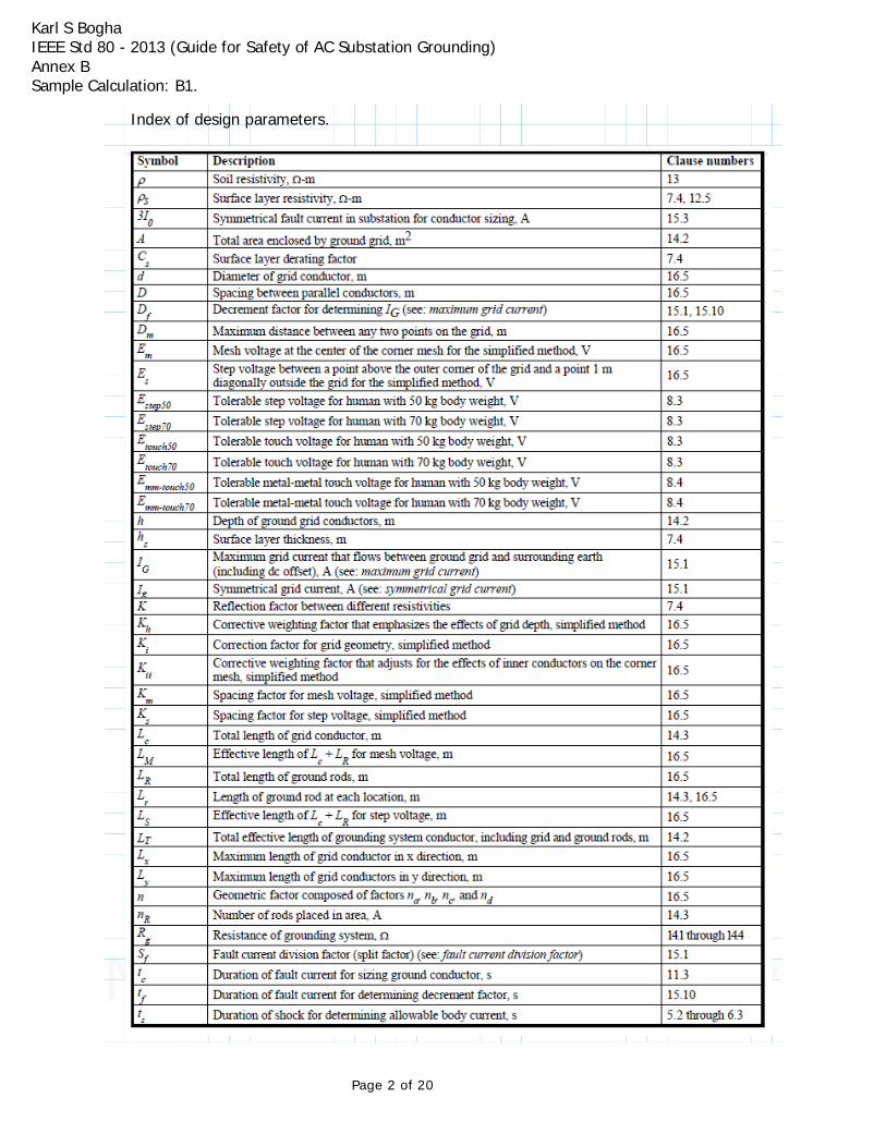
Index of design parameters.
Page 2 of 20
Karl S BoghaIEEE Std 80 - 2013 (Guide for Safety of AC Substation Grounding)Annex B Sample Calculation: B1.
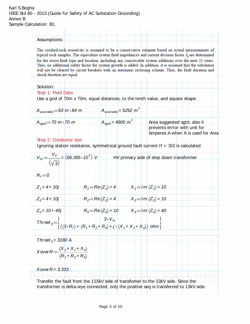
Assumptions:
Solution:Step 1: Field DataUse a grid of 70m x 70m, equal distances, to the tenth value, and square shape.
≔Aavailable ⋅63 m 84 m =Aavailable 5292 m2
Area suggested sgtd, also it prevents errror with unit for Amperes A when A is used for Area
≔Asgtd ⋅70 m 70 m =Asgtd 4900 m2
Step 2: Conductor sizeIgnoring station resistance, symmetrical ground fault current If = 3I0 is calculated
≔Vln =― ―Vll
⎛⎝‾‾3⎞⎠
⎛⎝ ⋅66.395 103⎞⎠V HV primary side of step down transformer
≔Rf 0
=Z1 +4 10j ≔R1 =Re⎛⎝Z1⎞⎠ 4 ≔X1 =Im⎛⎝Z1⎞⎠ 10
=Z2 +4 10j ≔R2 =Re⎛⎝Z2⎞⎠ 4 ≔X2 =Im⎛⎝Z2⎞⎠ 10
=Z0 +10 40j ≔R0 =Re⎛⎝Z0⎞⎠ 10 ≔X0 =Im⎛⎝Z0⎞⎠ 40
≔ThreeI0|||― ― ― ― ― ― ― ― ― ― ― ― ― ― ―
⋅3 Vln
⎛⎝ ++⎛⎝⋅3 Rf⎞⎠ ⎛⎝ ++R1 R2 R0⎞⎠ ⋅j ⎛⎝ ++X1 X2 X0⎞⎠⎞⎠ohm
|||
=ThreeI0 3180 A
≔XoverR ― ― ― ― ―⎛⎝ ++X1 X2 X0⎞⎠⎛⎝ ++R1 R2 R0⎞⎠
=XoverR 3.333
Transfer the fault from the 115kV side of transfomer to the 13kV side. Since the transformer is delta-wye connected, only the positive seq is transferred to 13kV side.
Page 3 of 20
Karl S BoghaIEEE Std 80 - 2013 (Guide for Safety of AC Substation Grounding)Annex B Sample Calculation: B1.
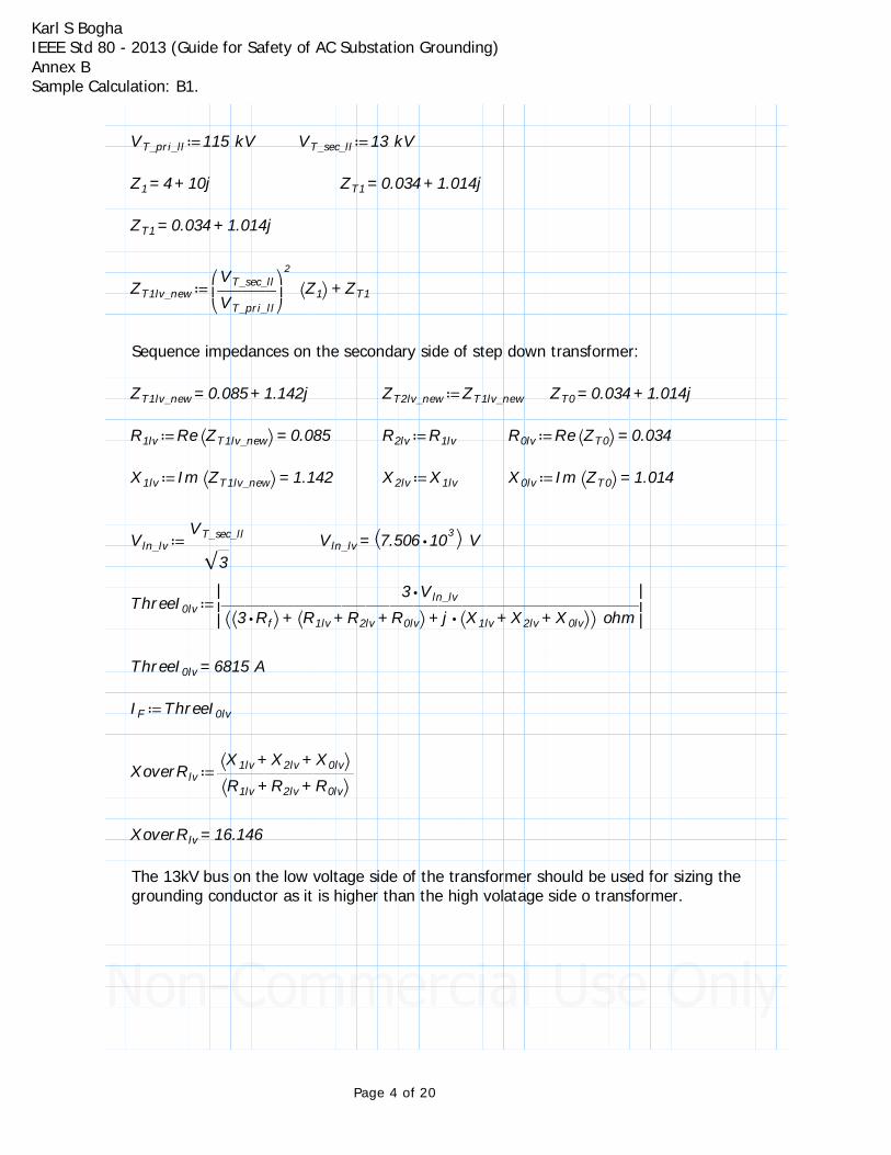
≔VT_pri_ll 115 kV ≔VT_sec_ll 13 kV
=Z1 +4 10j =ZT1 +0.034 1.014j
=ZT1 +0.034 1.014j
≔ZT1lv_new +⎛⎜⎝― ― ―VT_sec_ll
VT_pri_ll
⎞⎟⎠
2
⎛⎝Z1⎞⎠ ZT1
Sequence impedances on the secondary side of step down transformer:
=ZT1lv_new +0.085 1.142j ≔ZT2lv_new ZT1lv_new =ZT0 +0.034 1.014j
≔R1lv =Re⎛⎝ZT1lv_new⎞⎠ 0.085 ≔R2lv R1lv ≔R0lv =Re⎛⎝ZT0⎞⎠ 0.034
≔X1lv =Im⎛⎝ZT1lv_new⎞⎠ 1.142 ≔X2lv X1lv ≔X0lv =Im⎛⎝ZT0⎞⎠ 1.014
≔Vln_lv ― ― ―VT_sec_ll
‾‾3=Vln_lv⎛⎝ ⋅7.506 103⎞⎠V
≔ThreeI0lv|||― ― ― ― ― ― ― ― ― ― ― ― ― ― ― ― ― ―
⋅3 Vln_lv
⎛⎝ ++⎛⎝⋅3 Rf⎞⎠ ⎛⎝ ++R1lv R2lv R0lv⎞⎠ ⋅j ⎛⎝ ++X1lv X2lv X0lv⎞⎠⎞⎠ohm
|||
=ThreeI0lv 6815 A
≔IF ThreeI0lv
≔XoverRlv ― ― ― ― ― ―⎛⎝ ++X1lv X2lv X0lv⎞⎠⎛⎝ ++R1lv R2lv R0lv⎞⎠
=XoverRlv 16.146
The 13kV bus on the low voltage side of the transformer should be used for sizing the grounding conductor as it is higher than the high volatage side o transformer.
Page 4 of 20
Karl S BoghaIEEE Std 80 - 2013 (Guide for Safety of AC Substation Grounding)Annex B Sample Calculation: B1.
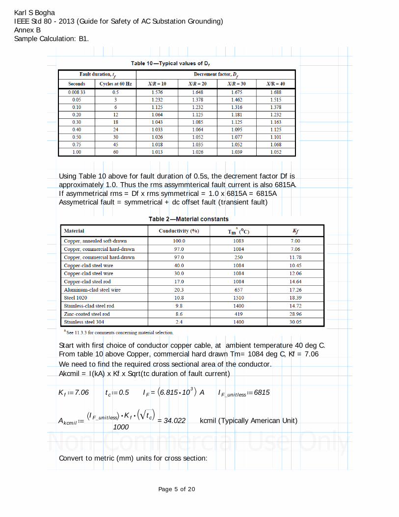
Using Table 10 above for fault duration of 0.5s, the decrement factor Df is approximately 1.0. Thus the rms assymmterical fault current is also 6815A.If asymmetrical rms = Df x rms symmetrical = 1.0 x 6815A = 6815AAssymetrical fault = symmetrical + dc offset fault (transient fault)
Start with first choice of conductor copper cable, at ambient temperature 40 deg C. From table 10 above Copper, commercial hard drawn Tm= 1084 deg C, Kf = 7.06We need to find the required cross sectional area of the conductor.Akcmil = I(kA) x Kf x Sqrt(tc duration of fault current)
≔Kf 7.06 ≔tc 0.5 =IF⎛⎝ ⋅6.815 103⎞⎠A ≔IF_unitless 6815
≔Akcmil =― ― ― ― ― ― ―⋅⋅⎛⎝IF_unitless⎞⎠Kf⎛⎝‾‾tc
⎞⎠1000
34.022 kcmil (Typically American Unit)
Convert to metric (mm) units for cross section:
Page 5 of 20

Karl S BoghaIEEE Std 80 - 2013 (Guide for Safety of AC Substation Grounding)Annex B Sample Calculation: B1.
≔Amm ⋅0.5097 Akcmil
=Amm 17.341 square milimetersReferring to electrical cable charts, the 17.3mm cross section will be accomodated by metric size 25mm cable or American Gauge number 4.
However this cable size will not have the adequate mechanical strength and ruggedness requirements for the installation.
A larger crosss section area cable size 70mm is used, and American Gauge 2/0. Stranded conductor, instead of solid.
≔A70 70 mm
≔dmm‾‾‾‾‾‾‾⎛⎜⎝― ―⋅A70 4π⎞⎟⎠
=dmm 9.441 ≔dm ― ―dmm
1000
=dm 0.0094 m approximately for stranded conductor
American Wire Gauge diameter for 2/0 in meter from wire charts:
≔dawg_m 0.0105
Since the diameter is in metric for AWG and Metric cables, we will approximate it to d = 0.01m
≔dm 0.01
Page 6 of 20
Karl S BoghaIEEE Std 80 - 2013 (Guide for Safety of AC Substation Grounding)Annex B Sample Calculation: B1.
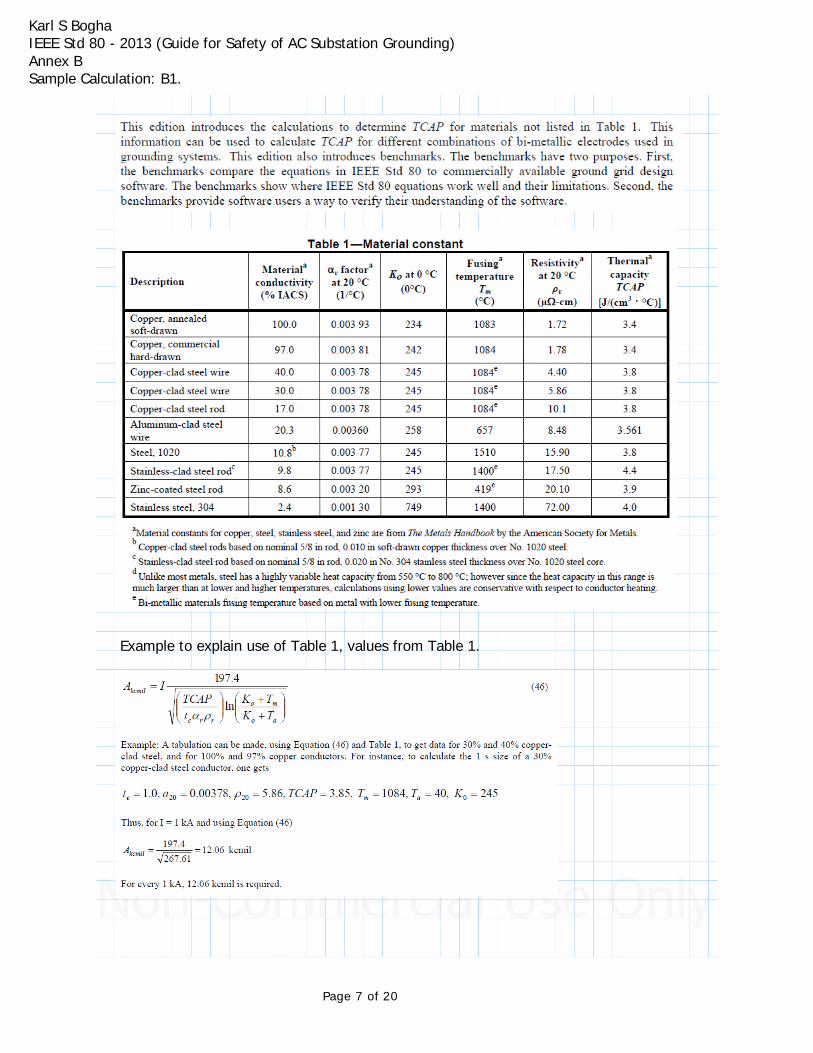
Example to explain use of Table 1, values from Table 1.
Page 7 of 20
Karl S BoghaIEEE Std 80 - 2013 (Guide for Safety of AC Substation Grounding)Annex B Sample Calculation: B1.
Use values from Table 1, copper clad steel wire with 30% conductivity.
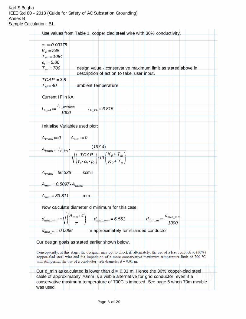
≔αr 0.00378≔K0 245≔Tm 1084≔ρr 5.86≔Tm 700 design value - conservative maximum limit as stated above in
description of action to take, user input.≔TCAP 3.8
≔Ta 40 ambient temperature
Current IF in kA
≔IF_kA ― ― ―IF_unitless
1000=IF_kA 6.815
Initialise Variables used pior:
≔Akcmil 0 ≔Amm 0
≔Akcmil ⋅IF_kA ― ― ― ― ― ― ― ― ―((197.4))
‾‾‾‾‾‾‾‾‾‾‾‾‾‾‾‾‾‾‾⋅⎛
⎜⎝― ― ―
TCAP⋅⋅tc αr ρr
⎞⎟⎠
ln⎛⎜⎝― ― ―
+K0 Tm
+K0 Ta
⎞⎟⎠
=Akcmil 66.336 kcmil
≔Amm ⋅0.5097 Akcmil
=Amm 33.811 mm
Now calculate diameter d minimum for this case:
≔dmin_mm‾‾‾‾‾‾‾‾⎛⎜⎝― ― ―
⋅Amm 4π
⎞⎟⎠
=dmin_mm 6.561 ≔dmin_m ― ― ―dmin_mm
1000
=dmin_m 0.0066 m approximately for stranded conductor
Our design goals as stated earlier shown below.
Our d_min as calculated is lower than d = 0.01 m. Hence the 30% copper-clad steel cable of approximately 70mm is a viable alternative for grid conductor, even if a conservative maximum temperature of 700C is imposed. See page 6 when 70m mcable was used.
Page 8 of 20
Karl S BoghaIEEE Std 80 - 2013 (Guide for Safety of AC Substation Grounding)Annex B Sample Calculation: B1.
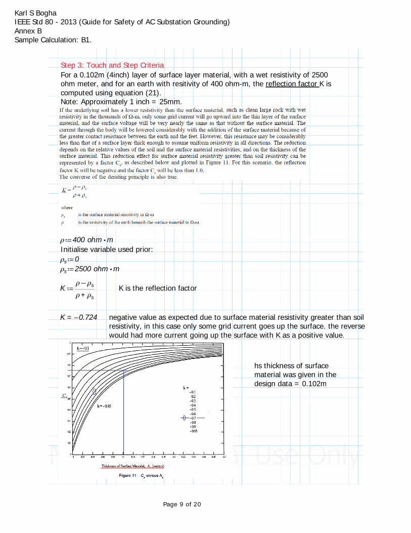
Step 3: Touch and Step CriteriaFor a 0.102m (4inch) layer of surface layer material, with a wet resistivity of 2500 ohm meter, and for an earth with resitivity of 400 ohm-m, the reflection factor K is computed using equation (21).Note: Approximately 1 inch = 25mm.
≔ρ ⋅400 ohm mInitialise variable used prior:≔ρs 0≔ρs ⋅2500 ohm m
≔K ― ―−ρ ρs
+ρ ρsK is the reflection factor
=K −0.724 negative value as expected due to surface material resistivity greater than soil resistivity, in this case only some grid current goes up the surface. the reverse would had more current going up the surface with K as a positive value.
hs thickness of surface material was given in the design data = 0.102m
Page 9 of 20
Karl S BoghaIEEE Std 80 - 2013 (Guide for Safety of AC Substation Grounding)Annex B Sample Calculation: B1.
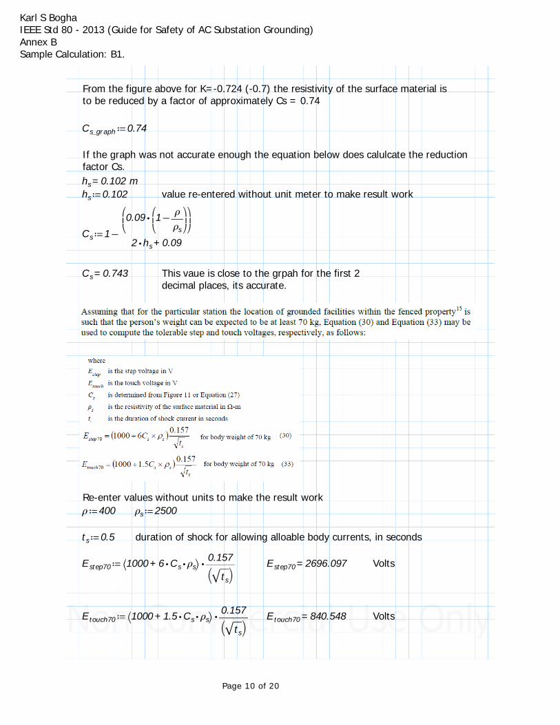
From the figure above for K=-0.724 (-0.7) the resistivity of the surface material is to be reduced by a factor of approximately Cs = 0.74
≔Cs_graph 0.74
If the graph was not accurate enough the equation below does calulcate the reduction factor Cs.
=hs 0.102 m≔hs 0.102 value re-entered without unit meter to make result work
≔Cs −1 ― ― ― ― ―
⎛⎜⎝
⋅0.09 ⎛⎜⎝−1 ―ρρs
⎞⎟⎠⎞⎟⎠
+⋅2 hs 0.09
=Cs 0.743 This vaue is close to the grpah for the first 2 decimal places, its accurate.
Re-enter values without units to make the result work≔ρ 400 ≔ρs 2500
≔ts 0.5 duration of shock for allowing alloable body currents, in seconds
≔Estep70 ⋅⎛⎝ +1000 ⋅⋅6 Cs ρs⎞⎠― ―0.157⎛⎝‾‾ts
⎞⎠=Estep70 2696.097 Volts
≔Etouch70 ⋅⎛⎝ +1000 ⋅⋅1.5 Cs ρs⎞⎠― ―0.157⎛⎝‾‾ts
⎞⎠=Etouch70 840.548 Volts
Page 10 of 20
Karl S BoghaIEEE Std 80 - 2013 (Guide for Safety of AC Substation Grounding)Annex B Sample Calculation: B1.
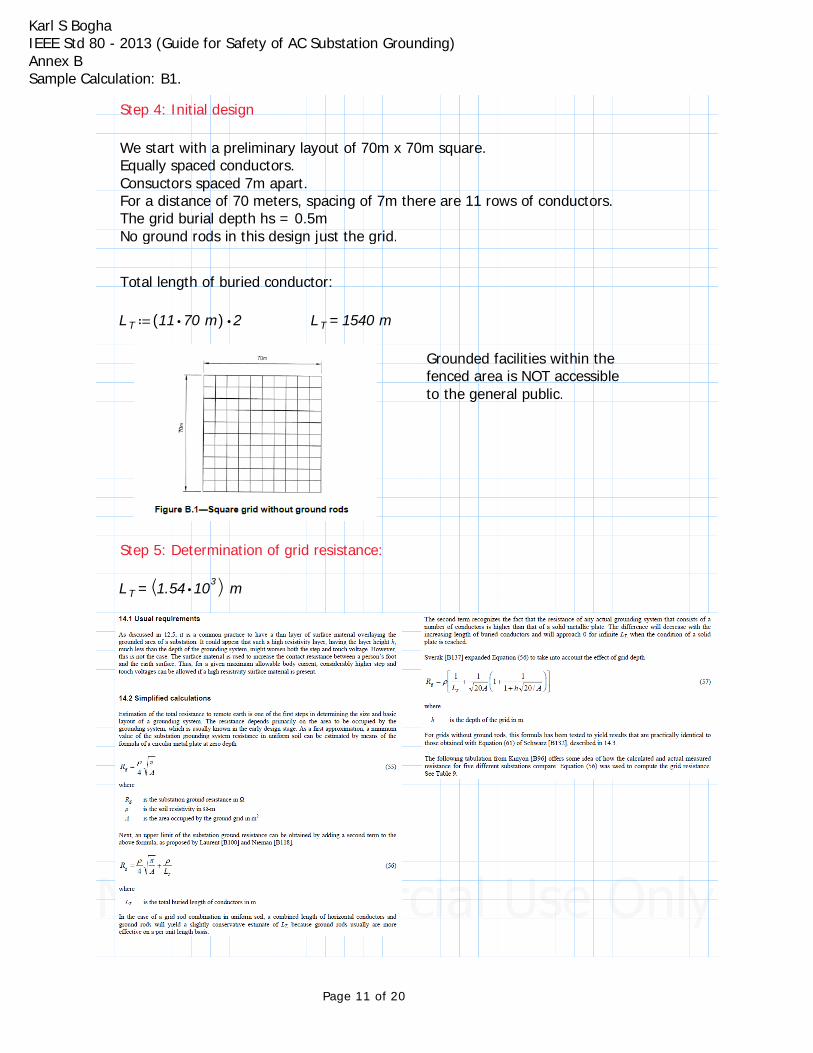
Step 4: Initial design
We start with a preliminary layout of 70m x 70m square.Equally spaced conductors.Consuctors spaced 7m apart.For a distance of 70 meters, spacing of 7m there are 11 rows of conductors.The grid burial depth hs = 0.5mNo ground rods in this design just the grid.
Total length of buried conductor:
≔LT ⋅(( ⋅11 70 m)) 2 =LT 1540 m
Grounded facilities within the fenced area is NOT accessible to the general public.
Step 5: Determination of grid resistance:
=LT⎛⎝ ⋅1.54 103⎞⎠m
Page 11 of 20
Karl S BoghaIEEE Std 80 - 2013 (Guide for Safety of AC Substation Grounding)Annex B Sample Calculation: B1.
≔ρ 400
≔Rg ⋅ρ⎛⎜⎜⎝
+⎛⎜⎝―
1LT
⎞⎟⎠
⋅⎛⎜⎝― ― ― ―
1‾‾‾‾‾‾‾⋅20 Asgtd
⎞⎟⎠
⎛⎜⎜⎝
+1 ― ― ― ― ― ―1
⎛⎜⎝
+1 ⋅h⎛⎜⎝
‾‾‾‾‾― ―20Asgtd
⎞⎟⎠
⎞⎟⎠
⎞⎟⎟⎠
⎞⎟⎟⎠
ohm m
=Rg 2.776 Ω
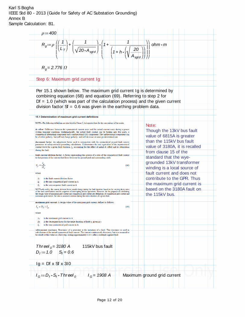
Step 6: Maximum grid current Ig
Per 15.1 shown below. The maximum grid current Ig is determined by combining equation (68) and equation (69). Referring to step 2 for Df = 1.0 (which was part of the calculation process) and the given current division factor Sf = 0.6 was given in the earthing problem data.
Note:Though the 13kV bus fault value of 6815A is greater than the 115kV bus fault value of 3180A, it is recalled from clause 15 of the standard that the wye-grounded 13kV transformer winding is a local source of fault current and does not contribute to the GPR. Thus the maximum grid current is based on the 3180A fault on the 115kV bus.
=ThreeI0 3180 A 115kV bus fault≔Df 1.0 =Sf 0.6
Ig = Df x Sf x 3I0
≔IG ⋅⋅Df Sf ThreeI0 =IG 1908 A Maximum ground grid current
Page 12 of 20
Karl S BoghaIEEE Std 80 - 2013 (Guide for Safety of AC Substation Grounding)Annex B Sample Calculation: B1.
Step 7: GPR (Ground Potential Rise).
Now it isnecessary to compare the product of Ig and Rg, or GPR, to the tolerable touch voltage Etouch70
≔GPR ⋅IG Rg
=GPR 5296 V
From step 3 the calculated value of Etouch70:
=Etouch70 840.548
The voltage of GPR is greater than Etouch70. The ground potential rise is greater than the touch voltage for the weight of a 70kg person. So this is UNACCEPTABLE. Therefore further design calculations/evaluations are necessary.
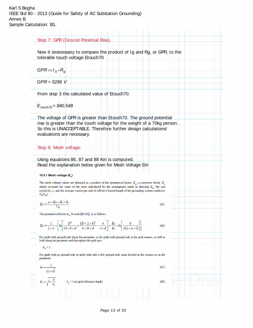
Step 8: Mesh voltage:
Using equations 86, 87 and 88 Km is computed. Read the explanation below given for Mesh Voltage Em
Page 13 of 20
Karl S BoghaIEEE Std 80 - 2013 (Guide for Safety of AC Substation Grounding)Annex B Sample Calculation: B1.
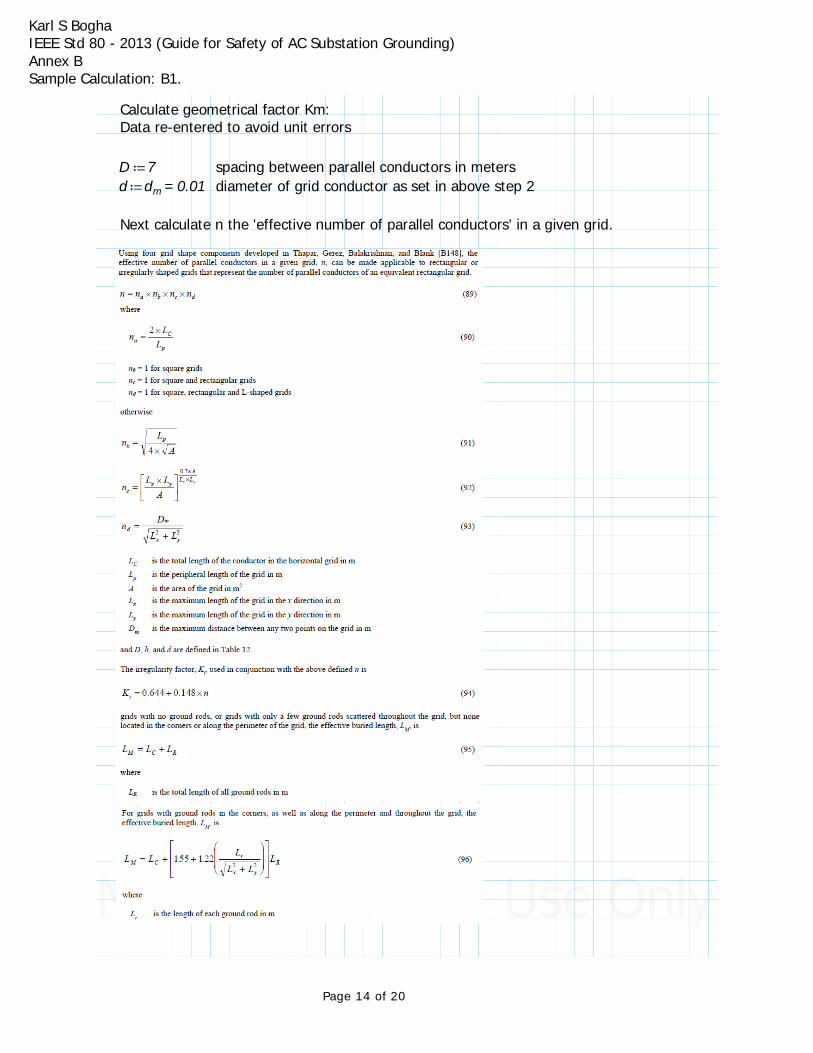
Calculate geometrical factor Km:Data re-entered to avoid unit errors
≔D 7 spacing between parallel conductors in meters≔d =dm 0.01 diameter of grid conductor as set in above step 2
Next calculate n the 'effective number of parallel conductors' in a given grid.
Page 14 of 20

Karl S BoghaIEEE Std 80 - 2013 (Guide for Safety of AC Substation Grounding)Annex B Sample Calculation: B1.
≔LC =LT 1540 m
≔LP =(( +++70 70 70 70)) m 280 m Perimeter of the grid
≔na ― ―⋅2 LC
LP=na 11
For a square grid nb, nc, and nd = 1≔nb 1 ≔nc 1 ≔nd 1
≔n ⋅⋅⋅na nb nc nd
=n 11
≔Kii ― ― ―1
(( ⋅2 n))―2n
=Kii 0.57
≔h0 1 h0 = 1m grid reference depth as in equation 88≔h 0.5 depth of buried conductor - reentered to avoid unit errors
≔Kh‾‾‾‾‾‾‾‾⎛⎜⎝
+1 ⎛⎜⎝―hh0
⎞⎟⎠⎞⎟⎠
=Kh 1.225
≔Km ⋅⎛⎜⎝― ―
12 π⎞⎟⎠
⎛⎜⎝
+ln⎛⎜⎝
−+― ― ―D2
⋅⋅16 h d― ― ― ―(( ⋅⋅D 2 h))
2
⋅⋅8 D d― ―
h⋅4 d
⎞⎟⎠
⋅― ―Kii
Khln⎛⎜⎝― ― ― ―
8⋅π (( −⋅2 n 1))
⎞⎟⎠
⎞⎟⎠
=Km 0.883 geometrical factor
≔Ki +0.644 ⋅0.148 n
=Ki 2.272
Calculate mesh voltage Em:
Em = (p x Ig x Km x Ki)/ (Lc + Lr)Here Lr is the ground rod length, which we do not have so the denominator is the total grid conductors length LT which is LCNote: Units removed to prevent inappropriate results in units. IGunitless = IG
Page 15 of 20
Karl S BoghaIEEE Std 80 - 2013 (Guide for Safety of AC Substation Grounding)Annex B Sample Calculation: B1.
≔LC =―LT
m1540 =ρ 400 ≔IGunitless =―
IG
A1907.854
≔Em ― ― ― ― ― ― ―⎛⎝ ⋅⋅⋅ρ IGunitless Km Ki⎞⎠
LC=Em 994.689 Volts
Step 9: Em versus Etouch:
=Etouch70 840.548 Volts
=Em 994.689 Volts
Mesh voltage Em calculated is HIGHER than the tolerable touch voltage Etouch70, this is UNACCEPTABLE.
The grid must be modified.
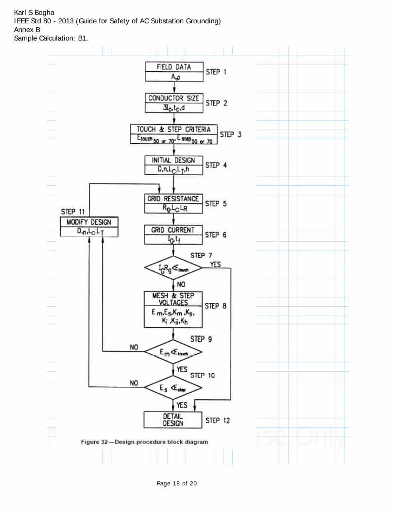
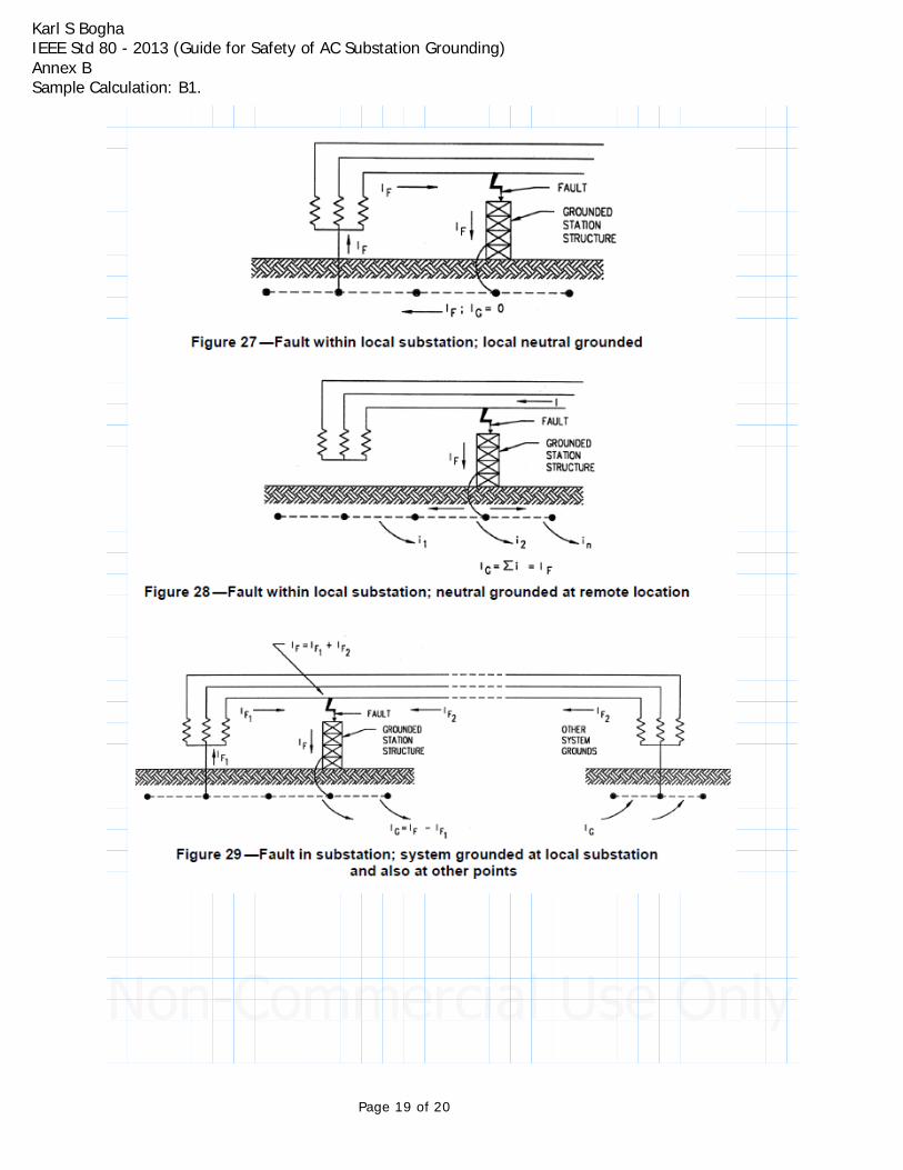
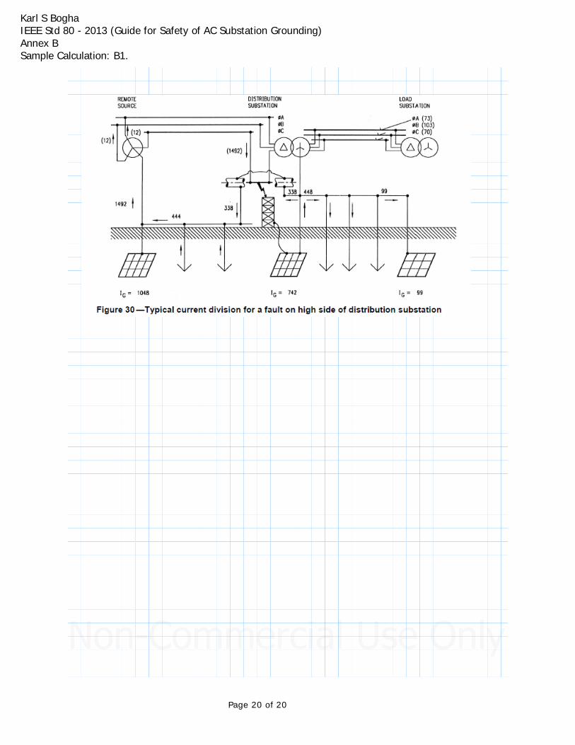
Design Procedure steps 1 through 12, and flow chart is provided.Also figures for ground faults at substations are provided after the flow chart.
Page 16 of 20

Karl S BoghaIEEE Std 80 - 2013 (Guide for Safety of AC Substation Grounding)Annex B Sample Calculation: B1.
Page 17 of 20
Karl S BoghaIEEE Std 80 - 2013 (Guide for Safety of AC Substation Grounding)Annex B Sample Calculation: B1.
Page 18 of 20
Karl S BoghaIEEE Std 80 - 2013 (Guide for Safety of AC Substation Grounding)Annex B Sample Calculation: B1.
Page 19 of 20
Karl S BoghaIEEE Std 80 - 2013 (Guide for Safety of AC Substation Grounding)Annex B Sample Calculation: B1.
Page 20 of 20


![CARB Document: ......CERT STD SFTP @ 4000 miles SFTP @ * miles CO [g/mi] com osite CERT STD CO sc03 CERT 0.09 STD 0.14 CERT 1.7 STD 8.0 CERT 0.04 STD 0.20 CERT 2.4 STD 2.7 CERT STD](https://static.fdocuments.us/doc/165x107/601fc6dcad09a45b411bb1e3/carb-document-cert-std-sftp-4000-miles-sftp-miles-co-gmi-com-osite.jpg)