KAP 140 Single Axis Autopilot -
49
KAP 140 Pilot’s Guide Bendix/King ® Autopilot System 006-18034-0000 Jun 98 a
Transcript of KAP 140 Single Axis Autopilot -

KAP 140Pilot’s Guide
Bendix/King®
Autopilot System
006-18034-0000Jun 98 a

WARNING
Information subject to the export control laws. This document, which includesany attachments and exhibits hereto, contains information subject toInternational Traffic in Arms Regulation (ITAR) or Export AdministrationRegulation (EAR) of 1979, which may not be exported, released or disclosedto foreign nationals inside or outside the U.S. without first obtaining an exportlicense. Violators of ITAR or EAR may be subject to a penalty of 10 yearsimprisonment and a fine of $1,000,000 under 22 U.S.C. 2778 or Section2410 of the Export Administration Act of 1979. Include this notice with anyreproduced portion of this document.
COPYRIGHT NOTICE
©1998 AlliedSignal, Inc.
Reproduction of this publication or any portion thereof by any means withoutthe express written permission of AlliedSignal Electronic and AvionicsSystems is prohibited. For further information contact the Manager, TechnicalPublications; AlliedSignal Electronic and Avionics Systems, One TechnologyCenter, 23500 West 105th Street, Olathe, Kansas 66061. Telephone: (913)782-0400.

KAP 140 AUTOPILOT SYSTEM
Table of Contents
iRev. 0Jun/98
Introduction . . . . . . . . . . . . . . . . . . . . . . . . . . . . . . . . . . . . . . . . . . . . . . . . . . . . .1General Description . . . . . . . . . . . . . . . . . . . . . . . . . . . . . . . . . . . . . . . . . . . . .2
KAP 140 Single Axis Autopilot System . . . . . . . . . . . . . . . . . . . . . . . . . . . .2KAP 140 Two Axis Autopilot System . . . . . . . . . . . . . . . . . . . . . . . . . . . . . .2KAP 140 Two Axis/Altitude Preselect Autopilot System . . . . . . . . . . . . . . .2
System Integration . . . . . . . . . . . . . . . . . . . . . . . . . . . . . . . . . . . . . . . . . . . . . .4Power Application and Preflight Tests . . . . . . . . . . . . . . . . . . . . . . . . . . . . . .8
KAP 140 Single Axis Operation . . . . . . . . . . . . . . . . . . . . . . . . . . . . . . . . . . . .9System Operating Modes . . . . . . . . . . . . . . . . . . . . . . . . . . . . . . . . . . . . . . . .12
Wing Leveler (ROL) Mode . . . . . . . . . . . . . . . . . . . . . . . . . . . . . . . . . . . . .12Heading Select (HDG) Mode . . . . . . . . . . . . . . . . . . . . . . . . . . . . . . . . . . .13Navigation (NAV) Mode Using a DG from HDG Mode (45° Intercept) . . . . . . . . . . . . . . . . . . . . . . . . . . . . . . . . . . . . . . . . . . . . . . .14Navigation (NAV) Mode Using a DG from ROL Mode (All Angle Intercept) . . . . . . . . . . . . . . . . . . . . . . . . . . . . . . . . . . . . . . . . . .16Approach (APR) Mode Using a DG from HDG Mode (45° Intercept) . . . . . . . . . . . . . . . . . . . . . . . . . . . . . . . . . . . . . . . . . . . . . . .20Approach (APR) Mode Using a DG from ROL Mode (All Angle Intercept) . . . . . . . . . . . . . . . . . . . . . . . . . . . . . . . . . . . . . . . . . .22Approach (APR) Mode Using an HSI . . . . . . . . . . . . . . . . . . . . . . . . . . . . .24Back Course (REV) Mode Using a DG from HDG Mode (45° Intercept) . . . . . . . . . . . . . . . . . . . . . . . . . . . . . . . . . . . . . . . . . . . . . . .26Back Course (REV) Mode Using a DG from ROL Mode(All Angle Intercept) . . . . . . . . . . . . . . . . . . . . . . . . . . . . . . . . . . . . . . . . . .28Back Course (REV) Mode Using an HSI . . . . . . . . . . . . . . . . . . . . . . . . . .30
Operations With The KAP 140 . . . . . . . . . . . . . . . . . . . . . . . . . . . . . . . . . . . .32Takeoff And Climb To Assigned Altitude . . . . . . . . . . . . . . . . . . . . . . . . . . .32GPS Capture Using DG . . . . . . . . . . . . . . . . . . . . . . . . . . . . . . . . . . . . . . . .34GPS Capture Using HSI . . . . . . . . . . . . . . . . . . . . . . . . . . . . . . . . . . . . . . .36Outbound On Front Course For Procedure Turn To LOC Approach Using DG . . . . . . . . . . . . . . . . . . . . . . . . . . . . . . . . . . . . . . . . . . . . . . . . . . .38Outbound On Front Course For Procedure Turn To LOC Approach Using HSI . . . . . . . . . . . . . . . . . . . . . . . . . . . . . . . . . . . . . . . . . . . . . . . . . . .40Front Course LOC Approach Using DG . . . . . . . . . . . . . . . . . . . . . . . . . . .42Front Course LOC Approach Using HSI . . . . . . . . . . . . . . . . . . . . . . . . . .44Outbound on GPS Approach Using DG . . . . . . . . . . . . . . . . . . . . . . . . . . .46Outbound on GPS Approach Using HSI . . . . . . . . . . . . . . . . . . . . . . . . . . .48Inbound on GPS Approach Using DG . . . . . . . . . . . . . . . . . . . . . . . . . . . . .50Inbound on GPS Approach Using HSI . . . . . . . . . . . . . . . . . . . . . . . . . . . .52
KAP 140 Two Axis Operation . . . . . . . . . . . . . . . . . . . . . . . . . . . . . . . . . . . . .55System Operating Modes . . . . . . . . . . . . . . . . . . . . . . . . . . . . . . . . . . . . . . . .57
Vertical Speed (VS) Mode . . . . . . . . . . . . . . . . . . . . . . . . . . . . . . . . . . . . .58Altitude Hold (ALT) Mode . . . . . . . . . . . . . . . . . . . . . . . . . . . . . . . . . . . . . .59
Operations With The KAP 140 . . . . . . . . . . . . . . . . . . . . . . . . . . . . . . . . . . . .60Takeoff And Climb To Assigned Altitude . . . . . . . . . . . . . . . . . . . . . . . . . . .60GPS Capture Using DG . . . . . . . . . . . . . . . . . . . . . . . . . . . . . . . . . . . . . . . .62

Table of Contents
ii KAP 140 AUTOPILOT SYSTEMRev. 0Jun/98
GPS Capture Using HSI . . . . . . . . . . . . . . . . . . . . . . . . . . . . . . . . . . . . . . .64Outbound On Front Course For Procedure Turn To ILS Approach Using DG . . . . . . . . . . . . . . . . . . . . . . . . . . . . . . . . . . . . . . . . . . . . . . . . . . .66Outbound On Front Course For Procedure Turn To ILS Approach Using HSI . . . . . . . . . . . . . . . . . . . . . . . . . . . . . . . . . . . . . . . . . . . . . . . . . . .68Front Course ILS Approach Using DG . . . . . . . . . . . . . . . . . . . . . . . . . . . .70Front Course ILS Approach Using HSI . . . . . . . . . . . . . . . . . . . . . . . . . . .72Outbound on GPS Approach Using DG . . . . . . . . . . . . . . . . . . . . . . . . . . .74Outbound on GPS Approach Using HSI . . . . . . . . . . . . . . . . . . . . . . . . . . .76Inbound on GPS Approach Using DG . . . . . . . . . . . . . . . . . . . . . . . . . . . . .78Inbound on GPS Approach Using HSI . . . . . . . . . . . . . . . . . . . . . . . . . . . .80
KAP 140 Two Axis with Altitude Preselect Operation . . . . . . . . . . . . . . . . .83System Operating Modes . . . . . . . . . . . . . . . . . . . . . . . . . . . . . . . . . . . . . . . .86
Vertical Speed (VS) Mode . . . . . . . . . . . . . . . . . . . . . . . . . . . . . . . . . . . . .86Altitude Hold (ALT) Mode . . . . . . . . . . . . . . . . . . . . . . . . . . . . . . . . . . . . . .87
Altitude Alerting and Preselect . . . . . . . . . . . . . . . . . . . . . . . . . . . . . . . . . . . .88Altitude Alerter . . . . . . . . . . . . . . . . . . . . . . . . . . . . . . . . . . . . . . . . . . . . . . .88Altimeter Setting . . . . . . . . . . . . . . . . . . . . . . . . . . . . . . . . . . . . . . . . . . . . .88Altitude Preselect . . . . . . . . . . . . . . . . . . . . . . . . . . . . . . . . . . . . . . . . . . . .89
Voice Messaging . . . . . . . . . . . . . . . . . . . . . . . . . . . . . . . . . . . . . . . . . . . . . .89Operations With The KAP 140 . . . . . . . . . . . . . . . . . . . . . . . . . . . . . . . . . . . .90
Takeoff And Climb To Assigned Altitude . . . . . . . . . . . . . . . . . . . . . . . . . . .90GPS Capture Using DG . . . . . . . . . . . . . . . . . . . . . . . . . . . . . . . . . . . . . . . .92GPS Capture Using HSI . . . . . . . . . . . . . . . . . . . . . . . . . . . . . . . . . . . . . . .94Outbound On Front Course For Procedure Turn To ILS Approach Using DG . . . . . . . . . . . . . . . . . . . . . . . . . . . . . . . . . . . . . . . . . . . . . . . . . . .96Outbound On Front Course For Procedure Turn To ILS Approach Using HSI . . . . . . . . . . . . . . . . . . . . . . . . . . . . . . . . . . . . . . . . . . . . . . . . . . .98Front Course ILS Approach Using DG . . . . . . . . . . . . . . . . . . . . . . . . . . .100Front Course ILS Approach Using HSI . . . . . . . . . . . . . . . . . . . . . . . . . .102Outbound on GPS Approach Using DG . . . . . . . . . . . . . . . . . . . . . . . . . .104Outbound on GPS Approach Using HSI . . . . . . . . . . . . . . . . . . . . . . . . . .106Inbound on GPS Approach Using DG . . . . . . . . . . . . . . . . . . . . . . . . . . . .108Inbound on GPS Approach Using HSI . . . . . . . . . . . . . . . . . . . . . . . . . . .110
KCS 55A Compass System . . . . . . . . . . . . . . . . . . . . . . . . . . . . . . . . . . . . . .113KI 525A Indicator . . . . . . . . . . . . . . . . . . . . . . . . . . . . . . . . . . . . . . . . . . . . .114Description of Indicator and Display Functions . . . . . . . . . . . . . . . . . . . . . .114Slaving Meter ( KA 51B) . . . . . . . . . . . . . . . . . . . . . . . . . . . . . . . . . . . . . . . .116KMT 112 Magnetic Slaving Transmitter . . . . . . . . . . . . . . . . . . . . . . . . . . . .117KG 102A Directional Gyro . . . . . . . . . . . . . . . . . . . . . . . . . . . . . . . . . . . . . .117Abnormal Circumstances . . . . . . . . . . . . . . . . . . . . . . . . . . . . . . . . . . . . . . .119Flight Procedures with the KCS 55A . . . . . . . . . . . . . . . . . . . . . . . . . . . . . .120
Abnormal Procedures . . . . . . . . . . . . . . . . . . . . . . . . . . . . . . . . . . . . . . . . . .127Autopilot Malfunction . . . . . . . . . . . . . . . . . . . . . . . . . . . . . . . . . . . . . . . . . .127

KAP 140 AUTOPILOT SYSTEM
Introduction
1Rev. 0Jun/98
Intr oduction
The KAP 140 Autopilot System is arate based digital autopilot systemoffering smooth performance andenhanced features found only inmore expensive autopilots. The firstof its type developed by AlliedSignal,this system brings digital technologyand reliability into the light aircraftcockpit.
It is also significant that the KAP 140series autopilots have beendesigned from their inception tointerface with the Silver Crown pack-age of products. Consider theadvantage of having your avionicsworking together as an integratedsystem rather than as a group ofcomponents built by several manu-factures.
Your new KAP 140 roll axis featuresinclude wing leveler, heading select,and VOR/LOC intercept and track-ing. The KAP 140 can also be cou-pled to GPS and RNAV receivers aswell. Roll rate information is derivedfrom the turn coordinator. Pitch axisfeatures include vertical speed,glideslope and altitude hold alongwith the optional altitude preselect.Pitch information is derived from apressure sensor and accelerometer.The KAP 140 Autopilot System oper-ates independent of the aircraft’sartificial horizon. Therefore, theautopilot retains roll stabilization andall vertical modes in the event of vac-uum system failure.
Internal monitors keep constant trackof the KAP 140’s status and providefor automatic shutdown of theautopilot or trim system in the eventof a malfunction. In addition to relia-bility, the KAP 140 is designed to beeasily maintained in the field.Qualified AlliedSignal ServiceCenters are located around theworld to provide assistance when-ever necessary.
To fully realize the capability of yournew panel mount digital autopilotsystem, you must understand theperformance capabilities and basicoperational requirements of the sys-tem. This pilot’s guide providesinformation to aid in this and isdivided up into six sections. The firstsection provides general familiariza-tion of each autopilot system includ-ing the associated panel mounteddisplays. The second sectiondescribes the KAP 140 Single AxisAutopilot System. The third sectiondescribes the KAP 140 Two AxisAutopilot System. The fourth sectiondescribes the KAP 140 TwoAxis/Altitude Preselect AutopilotSystem. The fifth section describesthe optional KCS 55A slaved com-pass system. The Sixth sectiondescribes abnormal procedures.

Introduction
2 KAP 140 AUTOPILOT SYSTEMRev. 0Jun/98
General Description
KAP 140 Single AxisAutopilot System
The KAP 140 Single Axis system isan entry level digital panel-mountautopilot, offering lateral modes onlywith an electric trim option.
KAP 140 Two AxisAutopilot System
The KAP 140 Two Axis system pro-vides both lateral and verticalmodes.
KAP 140 Two Axis/AltitudePreselect Autopilot System
The KAP 140 Two Axis system pro-vides both lateral and vertical modeswith altitude preselect.
L R
2 MIN.
TURN COORDINATOR
NO PITCHINFORMATION
D.C. ELEC.
GS GS
N33
30W
24
21 S15
12E
6
3
ı
AP
GKAP 140
HDG NAV APR REV ALT DN
UP
L R
2 MIN.
TURN COORDINATOR
NO PITCHINFORMATION
D.C. ELEC.
GS GSN
33
30W 24
21S
15
12E6
3
ı
AP
GKFC 140
HDG NAV APR REV ALT
ARM BARO
DN
UP
L R
2 MIN.
TURN COORDINATOR
NO PITCHINFORMATION
D.C. ELEC.
GS GS
N33
30W 24
21S
15
12E6
3
ı
AP
GKAP 140
HDG NAV APR REV

KAP 140 AUTOPILOT SYSTEM
Introduction
3Rev. 0Jun/98
KAP 140Two Axis Alt.
Preselect
KAP 140Two Axis
KAP 140Single Axis
HSI Optional Optional OptionalDG Standard Standard StandardTurn Coordinator Standard Standard StandardAutomatic Electric Elevator Trim Optional Optional OptionalManual Electric Trim Optional Optional Optional
FUNCTIONS/MODESALT Hold (ALT) Yes YesALT Preselect/ALERT YesHeading Select (HDG) Yes Yes YesNAV (VOR/RNAV/GPS) Yes Yes YesApproach (APR) Yes Yes YesGlideslope (GS) Yes YesBack Course (REV) Yes Yes YesControl Wheel Steering (CWS) Optional Optional OptionalVertical Speed Hld Yes YesAuto Capture Yes Yes YesAuto Track Yes Yes YesAll Angle Intercept Standard (with
DG or optionalHSI)
Standard (withDG or optional
HSI)
Standard (withDG or optional
HSI)Auto 45-degree Intercept Standard
(with DG only)Standard
(with DG only)Standard
(with DG only)
TESTManual and Auto Trim Monitor Both Both BothAcceleration Monitor Yes Yes
KAP 140 System Capabilities

Introduction
4 KAP 140 AUTOPILOT SYSTEMRev. 0Jun/98
System Integration
The individual system diagrams onpages 5, 6, and 7 show the compo-nents and their relationship in typicalKAP 140 Single Axis, KAP 140 TwoAxis, and KAP 140 Two Axis/AltitudePreselect systems. The actual com-ponents on individual systems mayvary slightly in order to optimize cer-tification and installation require-ments.
Each system has a number ofinputs: sensor outputs are shown inred; combination inputs are shown inblue; display outputs are shown inorange; and aircraft control shown ingreen. The systems diagramsreflect that the KAP 140 systemscontrol both pitch and roll axes of theaircraft.

KAP 140 AUTOPILOT SYSTEM
Introduction
5Rev. 0Jun/98
L R
2 MIN.
TURN COORDINATOR
NO PITCHINFORMATION
D.C. ELEC.
N33
30W
24
21S
15
12E
6
3
PUSH P
U S H
AIR
N
S
E
W
TO
FR
33
3024
21 15
126
3
OBS
GS
NAV
ı
NGS GS
33
30W
24
21 S15
12E
6
3
ı
NAV HDG
ı
KCS 305
MAN
CW
AUTO
CCW
- +
Turn Coordinator
Directional Gyro KI 204 or other Course Deviation Indicator
VOR/LOC/RNAV/GPS Deviation
MiddleMarker
KC 140 Single AxisComputer/Controller/Annunciator contains computerfunctions, modecontrol buttons,and annunciationsin a single unit.
KS 271C Roll Servo
KS 272C Pitch Trim Servo (Optional)
KI 525A PictorialNavigation Indicator
KCS 55A Slaved Compass System
(Optional)
KG102ASlaved DG
KMT 112Flux Detector
OR
KA 51BSlaving Accessory
Manual Electrical Trim
(Optional)
Autopilot Disconnect/
Trim Interrupt(Optional)
Control WheelSteering
(Optional)
AP
G
HDG NAV APR REV
KAP 140
TRIMFAIL
KAP 140 Single Axis System Diagram

Introduction
6 KAP 140 AUTOPILOT SYSTEMRev. 0Jun/98
L R
2 MIN.
TURN COORDINATOR
NO PITCHINFORMATION
D.C. ELEC.
N33
30W
24
21S
15
12E
6
3
PUSH P
U S H
AIR
N
S
E
W
TO
FR
33
3024
21 15
126
3
OBS
GS
NAV
ı
AP
GKAP 140
HDG NAV APR REV ALT UP
DN
NGS GS
33
30W
24
21 S15
12E
6
3
ı
NAV HDG
ı
KCS 305
MAN
CW
AUTO
CCW
- +
Turn Coordinator
Directional Gyro KI 204 or other Course Deviation Indicator
(not included)
KC 140 Two AxisComputer/Controller/Annunciator contains computerfunctions, modecontrol buttons,and annunciationsin a single unit.Also containsstatic pressure sensor and accelerometer.
KS 271C Roll Servo
KS 270C Pitch Servo
KS 272C Pitch Trim Servo
KI 525A PictorialNavigation Indicator
KCS 55A Slaved Compass System
(Optional)
KG102ASlaved DG
KMT 112Flux Detector
OR
KA 51BSlaving Accessory
Manual Electrical Trim
Autopilot Disconnect/
Trim Interrupt
Control WheelSteering
(optional)
TRIMFAIL
GlideslopeDeviation
VOR/LOC/RNAV/GPS Deviation
MiddleMarker
Static Pressure
KAP 140 Two Axis System Diagram

KAP 140 AUTOPILOT SYSTEM
Introduction
7Rev. 0Jun/98
L R
2 MIN.
TURN COORDINATOR
NO PITCHINFORMATION
D.C. ELEC.
N33
30W
24
21S
15
12E
6
3
PUSH P
U S H
AIR
N
S
E
W
TO
FR
33
3024
21 15
126
3
OBS
GS
NAV
ı
NGS GS
33
30W
24
21 S15
12E
6
3
ı
NAV HDG
ı
KCS 305
MAN
CW
AUTO
CCW
- +
Turn Coordinator
Directional Gyro KI 204 or other Course Deviation Indicator
(not included)
KC 140 Two Axis withAltitude PreselectComputer/Controller/Annunciator contains computerfunctions, modecontrol buttons,and annunciationsin a single unit. Alsocontains static pressure sensor and accelerometer.
KS 271C Roll Servo
KS 270C Pitch Servo
KS 272C Pitch Trim Servo
KI 525A PictorialNavigation Indicator
KCS 55A Slaved Compass System
(Optional)
KG102ASlaved DG
KMT 112Flux Detector
OR
KA 51BSlaving Accessory
Manual Electrical Trim
Autopilot Disconnect/
Trim Interrupt
Control WheelSteering
(optional)
AP
GKFC 140
HDG NAV APR REV ALT
ARM BARO
DN
UP
TRIMFAIL
GlideslopeDeviation
VOR/LOC/RNAV/GPS
Deviation
MiddleMarker
Static Pressure
BaroSetting
EncodingAltimeter
KAP 140 Two Axis/Altitude Preselect System Diagram

Introduction
8 KAP 140 AUTOPILOT SYSTEMRev. 0Jun/98
AP
GKAP 140
HDG NAV APR REV
KAP 140 Preflight Test Complete
AP
GKAP 140
HDG NAV APR REV
KAP 140 Preflight Test
Power Application and Preflight Tests
A preflight test is performedupon power application to the com-puter. This test is a sequence ofinternal checks that validate propersystem operation prior to allowingautopilot engagement. The preflighttest (PFT) sequence is indicated by“PFT” with an increasing number forthe sequence steps. Successfulcompletion of self test is identified byall display segments being illumi-nated (Display Test) and the discon-nect tone sounding.
For two-axis units only:
NOTE: Following the preflight test,the red P warning on the face of theautopilot may illuminate indicatingthat the pitch axis cannot beengaged. This condition should betemporary, lasting no more than 30seconds. The P will extinguish andnormal operation will be available.
If power to the autopilot is cycled inflight (i.e. through the autopilot circuitbreaker for instance) it is possiblethat a 5 minute delay may be neces-sary prior to autopilot engagement toallow the pitch axis accelerometercircuit to stabilize. Engagement priorto stabilization may result in mildlyerratic pitch axis behavior.

KAP 140 AUTOPILOT SYSTEM
Single Axis Operation
9Rev. 0Jun/98
AP
GKAP 140
HDG NAV APR REV
AP
GKAP 140
HDG NAV APR REV
P R
P R
1 3 4 5 62
7
Full Single-axis KAP 140 Display
Single-axis Flight Control Computer
KAP 140 Single Axis Operation
The KAP 140 is a high-performance digital, panel-mounted autopilot sys-tem for light aircraft.
1. AUTOPILOT ENGAGE/DISEN-GAGE (AP ) BUTTON - Whenpushed, engages autopilot if all logicconditions are met. The autopilotwill engage in the basic roll (ROL)mode which functions as a wing lev-eler. When pressed again, will disen-gage the autopilot.
2. ROLL AXIS (R) ANNUNCIATION- When illuminated, indicates failureof the roll axis and will disengage theautopilot and not allow engagement.
3. HEADING (HDG) MODE SELEC-TOR BUTTON - When pushed, willselect the Heading mode, whichcommands the airplane to turn toand maintain the heading selected
by the heading bug on either the DGor HSI. A new heading may beselected at any time and will result inthe airplane turning to the new head-ing. Button can also be used to tog-gle between HDG and ROL modes.This button will engage the autopilot.
4. NAVIGATION (NAV ) MODESELECTOR BUTTON - Whenpushed, will arm the navigationmode. The mode provides auto-matic beam capture and tracking ofVOR, LOC or GPS as selected forpresentation on the HSI or CDI.NAV mode is recommended forenroute navigation tracking.

Single Axis Operation
10 KAP 140 AUTOPILOT SYSTEMRev. 0Jun/98
5. APPROACH (APR ) MODESELECTOR BUTTON - Whenpushed, will arm the Approachmode. This mode provides auto-matic beam capture and tracking ofVOR, GPS and LOC, as selected forpresentation on the HSI or CDI.APR mode is recommended forinstrument approaches.
6. BACK COURSE APPROACH(REV) MODE SELECTOR BUTTON- When pushed, will arm the BackCourse approach mode. This modefunctions similarly to the approachmode except that the autopilotresponse to LOC signals isreversed.
7. ROLL MODE DISPLAY -Displays the active and armed rollmodes (ROL, HDG, NAV ARM,NAV, APR ARM, APR, REV ARM,REV). Also displayed will be flash-ing AP annunciation (5 seconds) ateach autopilot disconnect accompa-nied by an aural tone (for 2 sec-onds).

KAP 140 AUTOPILOT SYSTEM
Single Axis Operation
11Rev. 0Jun/98
This page intentionally left blank

Single Axis Operation
12 KAP 140 AUTOPILOT SYSTEMRev. 0Jun/98
L R
2 MIN.
TURN COORDINATOR
NO PITCHINFORMATION
D.C. ELEC.
AP
GKAP 140
HDG NAV APR REV
Wing Leveler (ROL) Mode
In the roll mode, the autopilotmaintains wings level flight.
1. Engage autopilot - Press AP
NOTE: The KAP 140 engages intoROL mode as a default.
System Operating Modes

KAP 140 AUTOPILOT SYSTEM
Single Axis Operation
13Rev. 0Jun/98
L R
2 MIN.
TURN COORDINATOR
NO PITCHINFORMATION
D.C. ELEC.
GS GS
N33
30W
2421 S
15
12E
6
3
ı
AP
GKAP 140
HDG NAV APR REV
N33
30W
24
21 S15
12E
6
3
P
U S H
PUSH
Heading Select (HDG) Mode
In the heading mode, theautopilot will fly a selected heading.The following steps should be takento operate in the heading mode:
1. Move the heading “bug” tothe desired heading on the DG orHSI using the Heading Select knob.
2. Depress the HDG button onthe KAP 140 to engage the headingselect mode. The autopilot will turnthe aircraft in the shortest directionto intercept and fly the heading.
3. If you move the heading“bug” again while the heading selectmode is engaged, the autopilot willimmediately turn the aircraft in thedirection of the newly selected head-ing.
4. Press HDG button again andthe autopilot will return to the ROLmode.
Single Axis Operation
14 KAP 140 AUTOPILOT SYSTEMRev. 0Jun/98
L R
2 MIN.
TURN COORDINATOR
NO PITCHINFORMATION
D.C. ELEC.
AP
GKAP 140
HDG NAV APR REV
N33
30
W24
21
S15
12
E6
3
P
U S H
PUSH
TO
FR
N
S
E
W
33
3024
2115
126
3
OBS
GS
NAV
ı
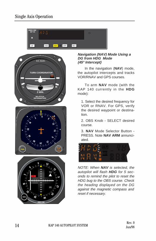
Navigation (NAV) Mode Using aDG from HDG Mode(45° Intercept)
In the navigation (NAV) mode,the autopilot intercepts and tracksVOR/RNAV and GPS courses.
To arm NAV mode (with theKAP 140 currently in the HDGmode):
1. Select the desired frequency forVOR or RNAV. For GPS, verifythe desired waypoint or destina-tion.
2. OBS Knob - SELECT desiredcourse.
3. NAV Mode Selector Button -PRESS. Note NAV ARM annunci-ated.
NOTE: When NAV is selected, theautopilot will flash HDG for 5 sec-onds to remind the pilot to reset theHDG bug to the OBS course. Checkthe heading displayed on the DGagainst the magnetic compass andreset if necessary.

KAP 140 AUTOPILOT SYSTEM
Single Axis Operation
15Rev. 0Jun/98
4. Heading Selector Knob -ROTATE BUG to agree with OBScourse.
Note Instruments: CDI needle to left.Intercept heading 45° to the left ofselected (heading bug) course.
5. If the Course Deviation Bar isgreater than 2 to 3 dots: theautopilot will annunciate NAVARM; when the computed capturepoint is reached the ARM annun-ciator will go out and the selectedcourse will be automatically cap-tured and tracked. If the D-Bar isless than 2 to 3 dots: the HDGmode will disengage upon select-ing NAV mode; the NAV annunci-ator will illuminate and the capture/track sequence will automaticallybegin.

Single Axis Operation
16 KAP 140 AUTOPILOT SYSTEMRev. 0Jun/98
L R
2 MIN.
TURN COORDINATOR
NO PITCHINFORMATION
D.C. ELEC.
AP
GKAP 140
HDG NAV APR REV
N33
30
W 2421
S15
12
E63
P
U S H
PUSH
TO
FR
N
S
E
W
33
3024
2115
126
3
OBS
GS
NAV
ı
Navigation (NAV) Mode Using aDG from ROL Mode(All Angle Intercept)
In the navigation (NAV) mode,the autopilot intercepts and tracksVOR/RNAV and GPS courses.
To arm NAV mode (with theKAP 140 currently in the ROLmode):
1. Maneuver the aircraft to thedesired intercept angle prior toselecting ROL mode.
2. Select the desired frequency forVOR or RNAV. For GPS, verifythe desired waypoint or destina-tion.
3. OBS Knob - SELECT desiredcourse.
4. NAV Mode Selector Button -PRESS. Note NAV ARM annunci-ated.
NOTE: When NAV is selected, theautopilot will flash HDG for 5 sec-onds to remind the pilot to reset theHDG bug to the OBS course. Checkthe heading displayed on the DGagainst the magnetic compass andreset if necessary.

KAP 140 AUTOPILOT SYSTEM
Single Axis Operation
17Rev. 0Jun/98
5. Heading Selector Knob -ROTATE BUG to agree with OBScourse.
Note Instruments: CDI needle to left.Intercept heading 30° to the left ofselected (heading bug) course.
6. If the Course Deviation Bar isgreater than 2 to 3 dots: theautopilot will annunciate NAVARM; when the computed capturepoint is reached the ARM annun-ciator will go out and the selectedcourse will be automatically cap-tured and tracked. If the D-Bar isless than 2 to 3 dots: the ROLmode will disengage upon select-ing NAV mode; the NAV annunci-ator will illuminate and the capture/track sequence will automaticallybegin.
Note: Intercept angles greater than45° can result in course overshootwhen close to the station.Therefore, intercept angles greaterthan 45° are not recommended.

Single Axis Operation
18 KAP 140 AUTOPILOT SYSTEMRev. 0Jun/98
L R
2 MIN.
TURN COORDINATOR
NO PITCHINFORMATION
D.C. ELEC.
AP
GKAP 140
HDG NAV APR REV
GS GS
N33
30
W 2421
S15
12
E63
ı
Navigation (NAV) Mode Using anHSI
In the navigation (NAV) mode,the autopilot intercepts and tracksVOR/RNAV and GPS courses.
To arm NAV mode (with theKAP 140 currently in the HDGmode):
1. Select the desired frequency forVOR or RNAV. For GPS, verifythe desired waypoint or destina-tion.
2. Course Bearing Pointer - SETto desired course.
3. Heading Selector Knob - SETBUG to provide desired interceptangle and engage HDG mode.Note NAV ARM annunciated.

4. NAV Mode Selector Button -PRESS.
5. If the Course Deviation Bar isgreater than 2 to 3 dots: the air-craft will continue in HDG mode(or ROL if HDG is not selected)with NAV ARM annunciated;when the computed capture pointis reached HDG will disengage,the ARM annunciator will go outand the selected course will beautomatically captured andtracked. If the D-Bar is less than 2to 3 dots: the HDG mode (or ROLif HDG is not selected) will disen-gage upon selecting NAV mode;the NAV annunciator will illumi-nate and the capture/ tracksequence will automatically begin.
Note: Intercept angles greater than45° can result in course overshootwhen close to the station. Therefore,intercept angles greater than 45° arenot recommended.
KAP 140 AUTOPILOT SYSTEM
Single Axis Operation
19Rev. 0Jun/98

Single Axis Operation
20 KAP 140 AUTOPILOT SYSTEMRev. 0Jun/98
L R
2 MIN.
TURN COORDINATOR
NO PITCHINFORMATION
D.C. ELEC.
AP
GKAP 140
HDG NAV APR REV
N33
30
W24
21
S15
12
E6
3
P
U S H
PUSH
TO
FR
N
S
E
W
33
3024
2115
126
3
OBS
GS
NAV
ı
Approach (APR) Mode Using aDG from HDG Mode(45° Intercept)
The Approach (APR ) modeallows the autopilot to intercept andtrack LOC, VOR/RNAV and GPScourses.
To arm APR mode (with theKAP 140 currently in the HDGmode):
1. Select the desired frequency forLOC, VOR or RNAV. For GPS,verify the desired approach.
2. OBS Knob - SELECT desiredapproach course. (For a localizer,set it to serve as a memory aid.)
3. APR Mode Selector Button -PRESS. Note APR ARM annun-ciated.
NOTE: When APR is selected, theautopilot will flash HDG for 5 sec-onds to remind the pilot to reset theHDG bug to the desired approachcourse. Check the heading dis-played on the DG against the mag-netic compass and reset if neces-sary.

KAP 140 AUTOPILOT SYSTEM
Single Axis Operation
21Rev. 0Jun/98
4. Heading Selector Knob -ROTATE BUG to agree withdesired approach course.
Note Instruments: CDI needle to left.Intercept heading 45° to the left ofselected (heading bug) course.
5. If the Course Deviation Bar isgreater than 2 to 3 dots: theautopilot will annunciate APRARM; when the computed capturepoint is reached the ARM annun-ciator will go out and the selectedcourse will be automatically cap-tured and tracked. If the D-Bar isless than 2 to 3 dots: the HDGmode will disengage upon select-ing APR mode; the APR annunci-ator will illuminate and the capture/track sequence will automaticallybegin.

Single Axis Operation
22 KAP 140 AUTOPILOT SYSTEMRev. 0Jun/98
L R
2 MIN.
TURN COORDINATOR
NO PITCHINFORMATION
D.C. ELEC.
AP
GKAP 140
HDG NAV APR REV
N33
30
W 24
21S
15
12
E63
P
U S H
PUSH
TO
FR
N
S
E
W
33
3024
2115
126
3
OBS
GS
NAV
ı
Approach (APR) Mode Using aDG from ROL Mode(All Angle Intercept)
The Approach (APR ) modeallows the autopilot to intercept andtrack LOC, VOR/RNAV and GPScourses.
To arm APR mode (with theKAP 140 currently in the ROLmode):
1. Maneuver the aircraft to thedesired intercept angle prior toselecting ROL mode.
2. Select the desired frequency forLOC, VOR or RNAV. For GPS,verify the desired approach.
3. OBS Knob - SELECT desiredapproach course. (For a localizer,set it to serve as a memory aid.)
4. APR Mode Selector Button -PRESS. Note APR ARM annun-ciated.
NOTE: When APR is selected, theautopilot will flash HDG for 5 sec-onds to remind the pilot to reset theHDG bug to the desired approachcourse. Check the heading dis-played on the DG against the mag-netic compass and reset if neces-sary.

KAP 140 AUTOPILOT SYSTEM
Single Axis Operation
23Rev. 0Jun/98
5. Heading Selector Knob -ROTATE BUG to agree withdesired approach course.
Note Instruments: CDI needle to left.Intercept heading 30° to the left ofselected (heading bug) course.
6. If the Course Deviation Bar isgreater than 2 to 3 dots: theautopilot will annunciate APRARM; when the computed capturepoint is reached the ARM annun-ciator will go out and the selectedcourse will be automatically cap-tured and tracked. If the D-Bar isless than 2 to 3 dots: the ROLmode will disengage upon select-ing APR mode; the APR annunci-ator will illuminate and the capture/track sequence will automaticallybegin.
Note: Intercept angles greater than45° can result in course overshootwhen close to the station.Therefore, intercept angles greaterthan 45° are not recommended.

Single Axis Operation
24 KAP 140 AUTOPILOT SYSTEMRev. 0Jun/98
L R
2 MIN.
TURN COORDINATOR
NO PITCHINFORMATION
D.C. ELEC.
AP
GKAP 140
HDG NAV APR REV
GS GS
N33
30
W 2421
S15
12
E63
ı
Approach (APR) Mode Using anHSI
The Approach (APR ) modeallows the autopilot to intercept andtrack LOC, VOR/RNAV and GPScourses.
To arm APR mode (with theKAP 140 currently in the HDGmode):
1. Select the desired frequency forLOC, VOR or RNAV. For GPS,verify the desired approach.
2. Course Bearing Pointer - SETto desired course.
3. Heading Selector Knob - SETBUG to provide desired interceptangle.
4. APR Mode Selector Button -PRESS. Note APR ARM annun-ciated.

KAP 140 AUTOPILOT SYSTEM
Single Axis Operation
25Rev. 0Jun/98
5. If the Course Deviation Bar isgreater than 2 to 3 dots: the air-craft will continue in HDG mode(or ROL if HDG is not selected)with the APR ARM annunciated;when the computed capture pointis reached HDG mode will disen-gage, the ARM annunciator will goout and the selected course will beautomatically captured andtracked. If the D-Bar is less than 2to 3 dots: the HDG mode (or ROLif HDG is not selected) will disen-gage upon selecting APR mode;the APR annunciator will illumi-nate and the capture/tracksequence will automatically begin.
Note: Intercept angles greater than45° can result in course overshootwhen close to the station.Therefore, intercept angles greaterthan 45° are not recommended.

Single Axis Operation
26 KAP 140 AUTOPILOT SYSTEMRev. 0Jun/98
L R
2 MIN.
TURN COORDINATOR
NO PITCHINFORMATION
D.C. ELEC.
AP
GKAP 140
HDG NAV APR REV
N33
30
W2421
S15
12
E6 3
P
U S H
PUSH
TO
FR
N
S
E
W
33
30 24
2115
126
3
OBS
GS
NAV
ı
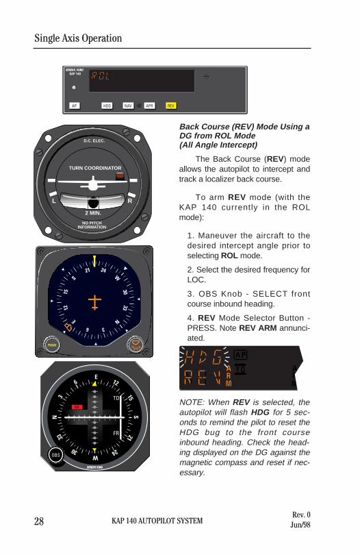
Back Course (REV) Mode Usinga DG from HDG Mode(45° Intercept)
The Back Course (REV) modeallows the autopilot to intercept andtrack a localizer back course.
To arm REV mode (with theKAP 140 currently in the HDGmode):
1. Select the desired frequency forLOC.
2. OBS Knob - SELECT frontcourse inbound heading.
3. REV Mode Selector Button -PRESS. Note REV ARM annun-ciated.
NOTE: When REV is selected, theautopilot will flash HDG for 5 sec-onds to remind the pilot to reset theHDG bug to the front courseinbound heading. Check the head-ing displayed on the DG against themagnetic compass and reset if nec-essary.

KAP 140 AUTOPILOT SYSTEM
Single Axis Operation
27Rev. 0Jun/98
4. Heading Selector Knob -ROTATE BUG to agree with theFRONT COURSE inbound head-ing.
Note Instruments: CDI needle to theright. Intercept heading 45° to theleft of the back course.
5. If the Course Deviation Bar isgreater than 2 to 3 dots: theautopilot will annunciate REVARM; when the computed capturepoint is reached the ARM annun-ciator will go out and the selectedcourse will be automatically cap-tured and tracked. If the D-Bar isless than 2 to 3 dots: the HDGmode will disengage upon select-ing REV mode; the REV annunci-ator will illuminate and the capture/track sequence will automaticallybegin.
Single Axis Operation
28 KAP 140 AUTOPILOT SYSTEMRev. 0Jun/98
L R
2 MIN.
TURN COORDINATOR
NO PITCHINFORMATION
D.C. ELEC.
AP
GKAP 140
HDG NAV APR REV
N33
30
W
2421
S
1512
E
6 3P
U S H
PUSH
TO
FR
N
S
E
W
33
30 24
2115
126
3
OBS
GS
NAV
ı
Back Course (REV) Mode Using aDG from ROL Mode(All Angle Intercept)
The Back Course (REV) modeallows the autopilot to intercept andtrack a localizer back course.
To arm REV mode (with theKAP 140 currently in the ROLmode):
1. Maneuver the aircraft to thedesired intercept angle prior toselecting ROL mode.
2. Select the desired frequency forLOC.
3. OBS Knob - SELECT frontcourse inbound heading.
4. REV Mode Selector Button -PRESS. Note REV ARM annunci-ated.
NOTE: When REV is selected, theautopilot will flash HDG for 5 sec-onds to remind the pilot to reset theHDG bug to the front courseinbound heading. Check the head-ing displayed on the DG against themagnetic compass and reset if nec-essary.

KAP 140 AUTOPILOT SYSTEM
Single Axis Operation
29Rev. 0Jun/98
5. Heading Selector Knob -ROTATE BUG to agree with theFRONT COURSE inbound head-ing.
Note Instruments: CDI needle to theright. Intercept heading 30° to theleft of the back course.
6. If the Course Deviation Bar isgreater than 2 to 3 dots: theautopilot will annunciate REVARM; when the computed capturepoint is reached the ARM annun-ciator will go out and the selectedcourse will be automatically cap-tured and tracked. If the D-Bar isless than 2 to 3 dots: the HDGmode will disengage upon select-ing REV mode; the REV annunci-ator will illuminate and the capture/track sequence will automaticallybegin.
Note: Intercept angles greater than45° can result in course overshootwhen close to the station.Therefore, intercept angles greaterthan 45° are not recommended.

Single Axis Operation
30 KAP 140 AUTOPILOT SYSTEMRev. 0Jun/98
L R
2 MIN.
TURN COORDINATOR
NO PITCHINFORMATION
D.C. ELEC.
AP
GKAP 140
HDG NAV APR REV
GS GS
N33
30
W2421
S15
12
E 63
ı
Back Course (REV) Mode Usingan HSI
The Back Course (REV) modeallows the autopilot to intercept andtrack a localizer back course.
To arm REV mode (with theKAP 140 currently in the HDGmode):
1. Select the desired frequency forLOC.
2. Course Bearing Pointer - SETto the FRONT COURSE inboundheading.
3. Heading Selector Knob - SETBUG to provide desired interceptangle.
4. REV Mode Selector Button -PRESS. Note REV ARM annunci-ated.

KAP 140 AUTOPILOT SYSTEM
Single Axis Operation
31Rev. 0Jun/98
5. If the Course Deviation Bar isgreater than 2 to 3 dots: the air-craft will continue in HDG mode(or ROL if HDG is not selected)with the REV ARM annunciated;when the computed capture pointis reached HDG mode will disen-gage, the ARM annunciator will goout and the selected course will beautomatically captured andtracked. If the D-Bar is less than 2to 3 dots: the HDG mode (or ROLif HDG is not selected) will disen-gage upon selecting REV mode;the REV annunciator will illumi-nate and the capture/tracksequence will automatically begin.
Note: Intercept angles greater than45° can result in course overshootwhen close to the station.Therefore, intercept angles greaterthan 45° are not recommended.

Single Axis Operation
32 KAP 140 AUTOPILOT SYSTEMRev. 0Jun/98 KAP 140 AUTOPILOT SYSTEM
Single Axis Operation
33Rev. 0Jun/98
L R
2 MIN.
TURN COORDINATOR
NO PITCHINFORMATION
D.C. ELEC.
GS GSN
3330
W
24 21S
1512
E
63
ı
AP
GKAP 140
HDG NAV APR REV
N
3330
W
24 21S
1512
E
63
P
U S H
PUSH
OR
L R
2 MIN.
TURN COORDINATOR
NO PITCHINFORMATION
D.C. ELEC.
GS GS
N33
30W
24
21 S15
12E
6
3
ı
AP
GKAP 140
HDG NAV APR REV
N33
30W
24
21 S15
12E
6
3
P
U S H
PUSH
OR
N
080°
010°
1 2 3 4
1 2 3 4
L R
2 MIN.
TURN COORDINATOR
NO PITCHINFORMATION
D.C. ELEC.
GS GS
N33
30W 24
21S
15
12E6
3
ı
AP
GKAP 140
HDG NAV APR REV
N33
30W 24
21S
15
12E6
3
P
U S H
PUSH
OR
L R
2 MIN.
TURN COORDINATOR
NO PITCHINFORMATION
D.C. ELEC.
GS GS
N33
30W 24
21S
15
12E6
3
ı
AP
GKAP 140
HDG NAV APR REV
N33
30W 24
21S
15
12E6
3
P
U S H
PUSH
OR
OPERATIONS WITH THE KAP 140
Takeoff And Climb To Assigned Altitude
3. The autopilot is responding to the heading selectmode with a left bank.
4. The autopilot has completed the turn and isnow established on a 010° heading.
1. The aircraft is well off the ground and estab-lished at a desired climb rate.The heading bug on the DG or HSI is turned tothe desired heading of 080° (runway heading).By depressing the HDG button on the KAP 140,the autopilot engages into the heading modeand maintains the selected heading of 080°.
2. The heading bug on the DG or HSI is turned tothe new desired heading of 010° and the aircraftbegins to respond with an immediate left turn.
Note: The autopilot controls only the roll axis. The PILOT must maintain control ofthe pitch and yaw axis.

KAP 140 AUTOPILOT SYSTEM
Single Axis Operation
35Rev. 0Jun/98
Single Axis Operation
34 KAP 140 AUTOPILOT SYSTEMRev. 0Jun/98
3. When the computed capture point is reached,the ROL annunciation changes to NAV and aright turn is initiated by the autopilot.
4. The turn is complete and the autopilot is track-ing the GPS course.
L R
2 MIN.
TURN COORDINATOR
NO PITCHINFORMATION
D.C. ELEC.
AP
GKAP 140
HDG NAV APR REV
N
3330
W
24 21S
1512
E
63
P
U S H
PUSH
TO
FR
N
S
E
W
3330
24 21
1512
63
OBS
GS
ı
L R
2 MIN.
TURN COORDINATOR
NO PITCHINFORMATION
D.C. ELEC.
AP
GKAP 140
HDG NAV APR REV
N
3330
W
24 21S
1512
E
63
P
U S H
PUSH
TO
FR
N
S
E
W
3330
24 21
1512
63
OBS
GS
ı
N
1
2
3
4
40°
010°
1. Continuing on heading 010°, a GPS waypoint isestablished. A 30° intercept is desired.
2. The HDG button is depressed to select ROLmode which will allow an “all angle intercept”.GPS data is selected for the CDI and the OBS isset to 040°. The NAV button is depressed andNAV ARM is annunciated. ROL will change toHDG and flash for five seconds. ROL will thenbe redisplayed. While the HDG annunciation isflashing, move the heading bug to the desiredcourse of 040°. The aircraft will remain wingslevel until the capture point.
GPS Capture Using DG
L R
2 MIN.
TURN COORDINATOR
NO PITCHINFORMATION
D.C. ELEC.
AP
GKAP 140
HDG NAV APR REV
N33
30W
24
21 S15
12E
6
3
P
U S H
PUSH
TO
FR
N
S
E
W
33
30 24
2115
126
3
OBS
GS
ı
L R
2 MIN.
TURN COORDINATOR
NO PITCHINFORMATION
D.C. ELEC.
AP
GKAP 140
HDG NAV APR REV
N33
30W
24
21 S15
12E
6
3
P
U S H
PUSH
TO
FR
N
S
E
W
3330
24 21
1512
63
OBS
GS
ı
* Description of GPS operation based on Bendix/King GPS receiver. Others mayrequire different operation.

KAP 140 AUTOPILOT SYSTEM
Single Axis Operation
37Rev. 0Jun/98
Single Axis Operation
36 KAP 140 AUTOPILOT SYSTEMRev. 0Jun/98
3. When the computed capture point is reached,the HDG annunciation changes to NAV and aright turn is initiated by the autopilot.
4. The turn is complete and the autopilot is track-ing the GPS course.
L R
2 MIN.
TURN COORDINATOR
NO PITCHINFORMATION
D.C. ELEC.
GS GSN
3330
W
24 21S
1512
E
63
ı
AP
GKAP 140
HDG NAV APR REV
L R
2 MIN.
TURN COORDINATOR
NO PITCHINFORMATION
D.C. ELEC.
GS GSN
3330
W
24 21S
1512
E
63
ı
AP
GKAP 140
HDG NAV APR REV
N
1
2
3
4
40°
010°
1. Continuing on heading 010°, a GPS waypoint isestablished. A 30° intercept is desired.
2. GPS data is selected for the HSI. The coursepointer is set to 040°. The NAV button isdepressed and NAV ARM is annunciated.
GPS Capture Using HSI
L R
2 MIN.
TURN COORDINATOR
NO PITCHINFORMATION
D.C. ELEC.
GS GS
N33
30W
24
21 S15
12E
6
3
ı
AP
GKAP 140
HDG NAV APR REV
L R
2 MIN.
TURN COORDINATOR
NO PITCHINFORMATION
D.C. ELEC.
GS GS
N33
30W
24
21 S15
12E
6
3
ı
AP
GKAP 140
HDG NAV APR REV
* Description of GPS operation based on Bendix/King GPS receiver. Others mayrequire different operation.

Single Axis Operation
38 KAP 140 AUTOPILOT SYSTEMRev. 0Jun/98 KAP 140 AUTOPILOT SYSTEM
Single Axis Operation
39Rev. 0Jun/98
3. At the desired point, HDG mode is used to initi-ate the procedure turn. Select HDG and set theheading bug to 283°. During the procedure turnoutbound, the CDI course index goes off scaleto the right. The aircraft is flying away from thelocalizer centerline at a 45° angle on a selectedheading of 283°.
* Check the heading displayed on the DG againstthe magnetic compass and reset if necessary.
4. Now you have reset the heading bug to 103°and made a 180° turn to this heading. This103° heading will intercept the front course of058°. You must now select the approach modeby depressing the APR button on the KAP 140.While the HDG annunciation is flashing movethe heading bug to the front course 058°. Sincethe 45° intercept is 103°, the aircraft will notturn until the front course is captured.
L R
2 MIN.
TURN COORDINATOR
NO PITCHINFORMATION
D.C. ELEC.
AP
GKAP 140
HDG NAV APR REV
N
3330W
2421
S
1512 E
63
P
U S H
PUSH
TO
FR
N
S
E
W
3330
2421
1512
63
OBS
GS
NAV
ı
L R
2 MIN.
TURN COORDINATOR
NO PITCHINFORMATION
D.C. ELEC.
AP
GKAP 140
HDG NAV APR REV
N33
30 W24
21S
15
12E6
3
P
U S H
PUSH
TO
FR
N
S
E
W
3330
2421
1512
63
OBS
GS
NAV
ı
N1
2
3
4
270°
283°
058°
238°
283°
103°
1. The aircraft is heading 270° with headingengaged. To intercept and fly the LOC frontcourse outbound, set the front course on theOBS and depress the back course (REV) but-ton. While the HDG annunciation is flashingmove the heading bug to the front course 058°.Since HDG was active upon selection of REV,the autopilot will initiate a 45° intercept to thelocalizer. In this case, the aircraft will turn to283°.
2. When the computed capture point is reached,auto-intercept mode is cancelled, the reverselocalizer mode is automatically activated and aleft turn outbound on the localizer is initiated bythe autopilot.
Note: The left-right deviations of the CDI coursedeviation needle are reversed (you must turn rightto center a deviation of the index to the left). Thisneedle reversing takes place because you are fly-ing outbound on a front course.
Outbound On Front Course For Procedure Turn To LOC Approach Using DG
L R
2 MIN.
TURN COORDINATOR
NO PITCHINFORMATION
D.C. ELEC.
AP
GKAP 140
HDG NAV APR REV
N33
30W
24
21S
15
12E
6
3
P
U S H
PUSH
TO
FR
N
S
E
W
3330
2421
1512
63
OBS
GS
NAV
ı
L R
2 MIN.
TURN COORDINATOR
NO PITCHINFORMATION
D.C. ELEC.
AP
GKAP 140
HDG NAV APR REV
N33
30
W24
21
S15
12
E 63
P
U S H
PUSH
TO
FR
N
S
E
W
3330
2421
1512
63
OBS
GS
NAV
ı

Single Axis Operation
40 KAP 140 AUTOPILOT SYSTEMRev. 0Jun/98 KAP 140 AUTOPILOT SYSTEM
Single Axis Operation
41Rev. 0Jun/98
3. At the desired point, HDG mode is used to initi-ate the procedure turn. Select HDG and set theheading bug to 283°. During the procedure turnoutbound, the deviation bar shows that the air-craft is flying away from the localizer centerlineat a 45° angle on a selected heading of 283°.
4. Now you have reset the heading bug to 103°and made a 180° turn to this heading. The103° heading will intercept the front course of058°. You must now select the approach modeby depressing the APR button on the KAP 140.Automatic capture of the localizer will occur.
L R
2 MIN.
TURN COORDINATOR
NO PITCHINFORMATION
D.C. ELEC.
GS GS
N33
30W24
21S
15
12 E6
3
ı
AP
GKAP 140
HDG NAV APR REV
L R
2 MIN.
TURN COORDINATOR
NO PITCHINFORMATION
D.C. ELEC.
GS GS
N
3330 W
2421
S
1512E
63
ı
AP
GKAP 140
HDG NAV APR REV
N1
23
4
270°
058°
238°
283°
103°
1. The aircraft is heading 270° with headingengaged. To intercept and fly the LOC frontcourse outbound, set the front course on theHSI and depress the back course (REV) but-ton. The back course (REV) mode is selected togo outbound on the front course. The capturepoint is now being computed based on closurerate.
2. When the computed capture point is reached,HDG mode is cancelled and reverse localizermode is automatically activated and a left turnoutbound on the localizer is initiated by theautopilot.
Note: The left-right deviations of the HSI courseneedle operate just as though you were flying afront course approach.
Outbound On Front Course For Procedure Turn To LOC Approach Using HSI
L R
2 MIN.
TURN COORDINATOR
NO PITCHINFORMATION
D.C. ELEC.
GS GS
N33
30W24
21S
15
12 E6
3
ı
AP
GKAP 140
HDG NAV APR REV
L R
2 MIN.
TURN COORDINATOR
NO PITCHINFORMATION
D.C. ELEC.
GS GS
N33
30
W2421
S15
12
E 63
ı
AP
GKAP 140
HDG NAV APR REV

Single Axis Operation
42 KAP 140 AUTOPILOT SYSTEMRev. 0Jun/98 KAP 140 AUTOPILOT SYSTEM
Single Axis Operation
43Rev. 0Jun/98
3. At the missed approach point, the pilot disen-gages the autopilot with the button on the con-trol wheel. This cancels all operating modes. Aflashing AP annunciation is displayed and a dis-connect tone will sound.
4. The pilot initiates the missed approach and sta-bilizes the aircraft in the climb. The headingbug is set to the missed approach heading of090°. By depressing the HDG button on theKAP 140, the autopilot engages into the head-ing mode, commencing a right turn to a head-ing of 090°.
L R
2 MIN.
TURN COORDINATOR
NO PITCHINFORMATION
D.C. ELEC.
AP
GKAP 140
HDG NAV APR REVN
3330
W 2421
S15
12
E63
P
U S H
PUSH
TO
FR
N
S
E
W
3330
2421
1512
63
OBS
GS
ı
L R
2 MIN.
TURN COORDINATOR
NO PITCHINFORMATION
D.C. ELEC.
AP
GKAP 140
HDG NAV APR REV
N33
30
W 24
21
S15
12
E63
P
U S H
PUSH
TO
FR
N
S
E
W
3330
2421
1512
63
OBS
GS
ı
N
12
34
058°
090°
238°
1. Continuing the maneuver on page 38, APR cou-pling occurs (HDG annunciation changes toAPR). The autopilot will capture the localizerand the CDI course index will center.
2. The autopilot is following the localizer. Theautopilot will make the bank changes as neces-sary to maintain localizer .
L R
2 MIN.
TURN COORDINATOR
NO PITCHINFORMATION
D.C. ELEC.
AP
GKAP 140
HDG NAV APR REV
N33
30W 24
21S
15
12E6
3
P
U S H
PUSH
TO
FR
N
S
E
W
3330
2421
1512
63
OBS
GS
ı
L R
2 MIN.
TURN COORDINATOR
NO PITCHINFORMATION
D.C. ELEC.
AP
GKAP 140
HDG NAV APR REV
N33
30
W 2421
S15
12
E63
P
U S H
PUSH
TO
FR
N
S
E
W
3330
2421
1512
63
OBS
GS
ı
Front Course LOC Approach Using DG

Single Axis Operation
44 KAP 140 AUTOPILOT SYSTEMRev. 0Jun/98 KAP 140 AUTOPILOT SYSTEM
Single Axis Operation
45Rev. 0Jun/98
3. At the missed approach point, the pilot disen-gages the autopilot with the button on the con-trol wheel. This cancels all operating modes.
4. The pilot initiates the missed approach and sta-bilizes the aircraft in the climb. The headingbug is set to the missed approach heading of090°. By depressing the HDG button on theKAP 140, the autopilot engages into the head-ing mode, commencing a right turn to a head-ing of 090°.
L R
2 MIN.
TURN COORDINATOR
NO PITCHINFORMATION
D.C. ELEC.
GS GS
N33
30
W 2421
S15
12
E63
ı
AP
GKAP 140
HDG NAV APR REV
L R
2 MIN.
TURN COORDINATOR
NO PITCHINFORMATION
D.C. ELEC.
GS GS
N33
30
W 2421
S15
12
E63
ı
AP
GKAP 140
HDG NAV APR REV
N
12
34
058°
090°
238°
1. Continuing the maneuver on page 40, APR cou-pling occurs (HDG annunciation changes toAPR). The autopilot will capture the localizerand the CDI course index will center.
2. The autopilot is following the localizer. Theautopilot will make bank changes as necessaryto maintain localizer.
L R
2 MIN.
TURN COORDINATOR
NO PITCHINFORMATION
D.C. ELEC.
GS GS
N33
30W 24
21S
15
12E6
3
ı
AP
GKAP 140
HDG NAV APR REV
L R
2 MIN.
TURN COORDINATOR
NO PITCHINFORMATION
D.C. ELEC.
GS GS
N33
30
W 2421
S15
12
E63
ı
AP
GKAP 140
HDG NAV APR REV
Front Course LOC Approach Using HSI
KAP 140 AUTOPILOT SYSTEM
Single Axis Operation
47Rev. 0Jun/98
Single Axis Operation
46 KAP 140 AUTOPILOT SYSTEMRev. 0Jun/98
N
12
3
4
058°
270°
238°
283°
103°
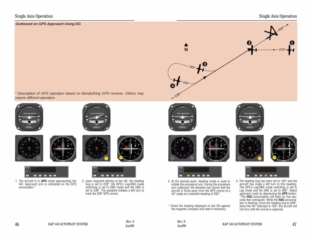
3. At the desired point, heading mode is used toinitiate the procedure turn. During the procedureturn outbound, the deviation bar shows that theaircraft is flying away from the GPS course at a45° angle on a selected heading of 283°.
* Check the heading displayed on the DG againstthe magnetic compass and reset if necessary.
4. The heading bug has been set to 103° and theaircraft has made a left turn to this heading.The GPS’s Leg/OBS mode switching is set toLeg mode and the OBS is set to 058°. Selectapproach mode by depressing the APR button.*The HDG annunciation will flash for five sec-onds then extinguish. While the HDG annuncia-tion is flashing, move the heading bug to 058°.Since the 45° intercept is 103°, the aircraft willnot turn until the course is captured.
1. The aircraft is in APR mode approaching theIAF. Approach arm is indicated on the GPSannunciator.*
2. Upon waypoint alerting at the IAF, the headingbug is set to 238°, the GPS’s Leg/OBS modeswitching is set to OBS mode and the OBS isset to 238°. The autopilot initiates a left turn totrack the 238° GPS course.
Outbound on GPS Approach Using DG
L R
2 MIN.
TURN COORDINATOR
NO PITCHINFORMATION
D.C. ELEC.
AP
GKAP 140
HDG NAV APR REV ALT
N33
30W24
21S
15
12 E6
3
P
U S H
PUSH
TO
FR
N
S
E
W
33
3024
2115
12 6
3
OBS
GS
ı
L R
2 MIN.
TURN COORDINATOR
NO PITCHINFORMATION
D.C. ELEC.
AP
GKAP 140
HDG NAV APR REV ALT
N33
30
W24
21
S15
12
E 63
P
U S H
PUSH
TO
FR N
S
E
W
3330
2421
1512
63
OBS
GS
ı
L R
2 MIN.
TURN COORDINATOR
NO PITCHINFORMATION
D.C. ELEC.
AP
GKAP 140
HDG NAV APR REV ALT
N
33
30W
24
21S
15
12 E6
3P
U S H
PUSH
TO
FR N
S
E
W
3330
2421
1512
63
OBS
GS
ı
L R
2 MIN.
TURN COORDINATOR
NO PITCHINFORMATION
D.C. ELEC.
AP
GKAP 140
HDG NAV APR REV ALT
N
33
30 W
24
21S
15
12E6
3
P
U S H
PUSH
TO
FR
N
S
E
W
3330
2421
1512
63
OBS
GS
ı
* Description of GPS operation based on Bendix/King GPS receiver. Others mayrequire different operation.

KAP 140 AUTOPILOT SYSTEM
Single Axis Operation
49Rev. 0Jun/98
Single Axis Operation
48 KAP 140 AUTOPILOT SYSTEMRev. 0Jun/98
3. At the desired point, heading mode is used toinitiate the procedure turn. During the procedureturn outbound, the deviation bar shows that theaircraft is flying away from the GPS course at a45° angle on a selected heading of 283°.
4. The heading bug has been set to 103° and theaircraft has made a left turn to this heading.The GPS’s Leg/OBS mode switching is set toLeg mode and the course pointer is set to058°. Select approach mode by depressing theAPR button.
1. The aircraft is in APR mode approaching theIAF. Approach arm is indicated on the GPSannunciator.*
2. Upon waypoint alerting at the IAF, the coursepointer is set to 238°, the GPS’s Leg/OBS modeswitching is set to OBS mode. The autopilot ini-tiates a left turn to track the 238° GPS course.
L R
2 MIN.
TURN COORDINATOR
NO PITCHINFORMATION
D.C. ELEC.
GS GS
N33
30W24
21S
15
12 E6
3
ı
AP
GKAP 140
HDG NAV APR REV ALT
L R
2 MIN.
TURN COORDINATOR
NO PITCHINFORMATION
D.C. ELEC.
GS GS
N33
30
W2421
S15
12
E 63
ı
AP
GKAP 140
HDG NAV APR REV ALT
L R
2 MIN.
TURN COORDINATOR
NO PITCHINFORMATION
D.C. ELEC.
GS GS
N33
30W24
21S
15
12 E6
3
ı
AP
GKAP 140
HDG NAV APR REV ALT
L R
2 MIN.
TURN COORDINATOR
NO PITCHINFORMATION
D.C. ELEC.
GS GS
N33
30 W24
21S
15
12E6
3
ı
AP
GKAP 140
HDG NAV APR REV ALT
N
12
3
4
058°
270°
238°
283°
103°
Outbound on GPS Approach Using HSI
* Description of GPS operation based on Bendix/King GPS receiver. Others mayrequire different operation.

KAP 140 AUTOPILOT SYSTEM
Single Axis Operation
51Rev. 0Jun/98
Single Axis Operation
50 KAP 140 AUTOPILOT SYSTEMRev. 0Jun/98
N
1
2
34
058°
090°
238°
FAF
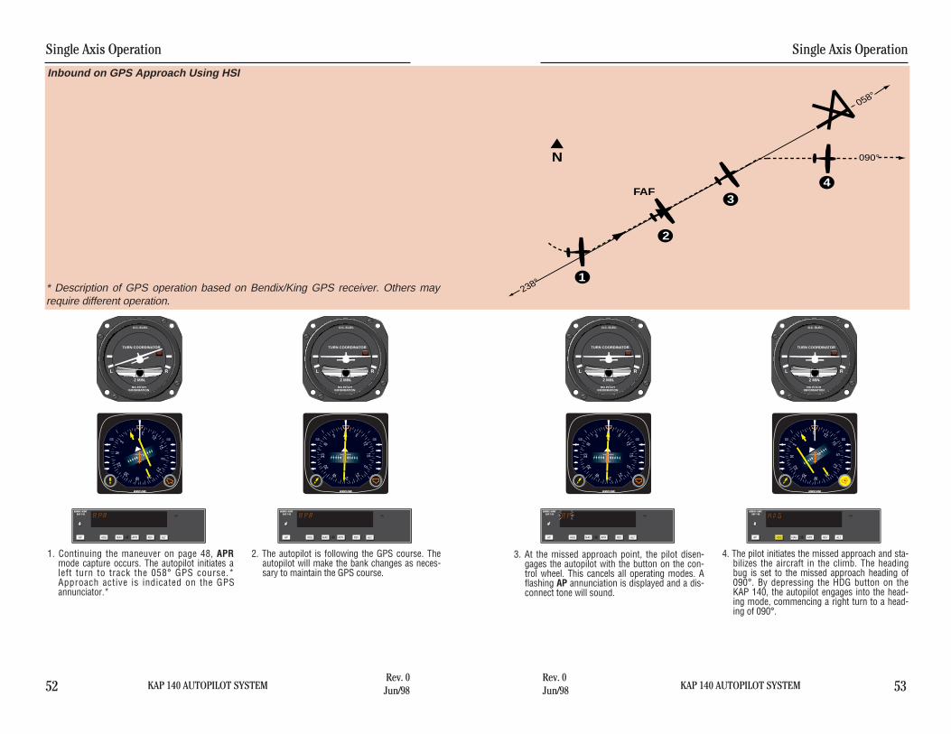
3. At the missed approach point, the pilot disen-gages the autopilot with the button on the con-trol wheel. This cancels all operating modes. Aflashing AP annunciation is displayed and a dis-connect tone will sound.
4. The pilot initiates the missed approach and sta-bilizes the aircraft in the climb. The headingbug is set to the missed approach heading of090°. By depressing the HDG button on theKAP 140, the autopilot engages into the head-ing mode, commencing a right turn to a head-ing of 090°.
1. Continuing the maneuver on page 46, APRmode capture occurs. The autopilot initiates aleft turn to track the 058° GPS course.Approach active is indicated on the GPSannunciator.*
2. The autopilot is following the GPS course. Theautopilot will make the bank changes as neces-sary to maintain the GPS course.
Inbound on GPS Approach Using DG
L R
2 MIN.
TURN COORDINATOR
NO PITCHINFORMATION
D.C. ELEC.
AP
GKAP 140
HDG NAV APR REV ALT
N33
30W 24
21S
15
12E6
3
P
U S H
PUSH
TO
FR
N
S
E
W
3330
2421
1512
63
OBS
GS
ı
L R
2 MIN.
TURN COORDINATOR
NO PITCHINFORMATION
D.C. ELEC.
AP
GKAP 140
HDG NAV APR REV ALT
N33
30
W 2421
S15
12
E63
P
U S H
PUSH
TO
FR
N
S
E
W
3330
2421
1512
63
OBS
GS
ı
L R
2 MIN.
TURN COORDINATOR
NO PITCHINFORMATION
D.C. ELEC.
AP
GKAP 140
HDG NAV APR REV ALTN
3330
W 2421
S15
12
E63
P
U S H
PUSH
TO
FR
N
S
E
W
3330
2421
1512
63
OBS
GS
ı
L R
2 MIN.
TURN COORDINATOR
NO PITCHINFORMATION
D.C. ELEC.
AP
GKAP 140
HDG NAV APR REV ALT
N33
30 W24
21S
15
12E6
3
P
U S H
PUSH
TO
FR
N
S
E
W
3330
2421
1512
63
OBS
GS
ı
* Description of GPS operation based on Bendix/King GPS receiver. Others mayrequire different operation.
KAP 140 AUTOPILOT SYSTEM
Single Axis Operation
53Rev. 0Jun/98
Single Axis Operation
52 KAP 140 AUTOPILOT SYSTEMRev. 0Jun/98
N
1
2
34
058°
090°
238°
FAF
3. At the missed approach point, the pilot disen-gages the autopilot with the button on the con-trol wheel. This cancels all operating modes. Aflashing AP annunciation is displayed and a dis-connect tone will sound.
4. The pilot initiates the missed approach and sta-bilizes the aircraft in the climb. The headingbug is set to the missed approach heading of090°. By depressing the HDG button on theKAP 140, the autopilot engages into the head-ing mode, commencing a right turn to a head-ing of 090°.
1. Continuing the maneuver on page 48, APRmode capture occurs. The autopilot initiates aleft turn to track the 058° GPS course.*Approach active is indicated on the GPSannunciator.*
2. The autopilot is following the GPS course. Theautopilot will make the bank changes as neces-sary to maintain the GPS course.
Inbound on GPS Approach Using HSI
* Description of GPS operation based on Bendix/King GPS receiver. Others mayrequire different operation.
L R
2 MIN.
TURN COORDINATOR
NO PITCHINFORMATION
D.C. ELEC.
GS GS
N33
30W 24
21S
15
12E6
3
ı
AP
GKAP 140
HDG NAV APR REV ALT
L R
2 MIN.
TURN COORDINATOR
NO PITCHINFORMATION
D.C. ELEC.
GS GS
N33
30
W 2421
S15
12
E63
ı
AP
GKAP 140
HDG NAV APR REV ALT
L R
2 MIN.
TURN COORDINATOR
NO PITCHINFORMATION
D.C. ELEC.
GS GS
N33
30
W 2421
S15
12
E63
ı
AP
GKAP 140
HDG NAV APR REV ALT
L R
2 MIN.
TURN COORDINATOR
NO PITCHINFORMATION
D.C. ELEC.
GS GS
N33
30 W24
21S
15
12E6
3
ı
AP
GKAP 140
HDG NAV APR REV ALT
KAP 140 AUTOPILOT SYSTEM
Abnormal Procedures
127Rev. 0Jun/98
Abnormal Pr ocedures
Autopilot Malfunction
An autopilot, autopilot trim or manual electric trim malfunction may be recog-nized as an uncommanded deviation in the airplane flight path or when thereis abnormal control wheel or trim wheel motion. The primary concern in react-ing to an autopilot or trim malfunction, or to an automatic disconnect of theautopilot, is in maintaining control of the airplane. Immediately grasp the con-trol wheel and press and hold down the A/P DISC/TRIM INTER switchthroughout the recovery. Manipulate the controls as required to safely main-tain operation of the airplane within all of its operating limitations.
CAUTION: Refer to the Airplane Flight Manual or the Airplane Flight ManualSupplement for your particular aircraft for pertinent emergency procedures.

Abnormal Procedures
128 KAP 140 AUTOPILOT SYSTEMRev. 0Jun/98
This page intentionally left blank

AlliedSignal, Inc.Electronic and Avionics SystemsOne Technology Center23500 West 105th StreetOlathe, Kansas 66061FAX 913-791-1302Telephone: (913) 782-0400
006-18034-0000
Rev. 0 6/98 a
Printed 2.5K 6/98 CW