
Kamran Ahsan - gray-world.netgray-world.net/papers/ahsan02.pdf · Abstract Covert Channel Analysis...
134
Covert Channel Analysis and Data Hiding in TCP/IP by Kamran Ahsan A thesis submitted in conformity with the requirements for the degree of Masters of Applied Science Edward S. Rogers Sr. Graduate Department of Electrical and Computer Engineering University of Toronto Copyright c 2002 by Kamran Ahsan
Transcript of Kamran Ahsan - gray-world.netgray-world.net/papers/ahsan02.pdf · Abstract Covert Channel Analysis...

Covert Channel Analysis and Data Hiding in TCP/IP
by
Kamran Ahsan
A thesis submitted in conformity with the requirementsfor the degree of Masters of Applied Science
Edward S. Rogers Sr. Graduate Department of Electrical and ComputerEngineering
University of Toronto
Copyright c© 2002 by Kamran Ahsan

Abstract
Covert Channel Analysis and Data Hiding in TCP/IP
Kamran Ahsan
Masters of Applied Science
Edward S. Rogers Sr. Graduate Department of Electrical and Computer Engineering
University of Toronto
2002
This thesis investigates the existence of covert channels in computer networks by
analyzing the transport and the Internet layers of the TCP/IP protocol suite. Two ap-
proaches for data hiding are identified: packet header manipulation and packet sorting.
Each scenario facilitates the interaction of steganographic principles with the existing
network security environment. Specifically, we show how associating additional informa-
tion with IPv4 headers can ease up security mechanisms in network nodes like routers,
firewalls and for services such as authentication, audit, and billing. Furthermore, use
of packet sorting with the IP Sec framework results in an enhanced network security
architecture.
The packet sorting approach is simulated at the network layer which provides a fea-
sibility of packet sorting under varying network conditions. While bridging the areas of
data hiding, network protocols and network security, both techniques have potential for
practical data hiding at the transport and network layers.
i

Acknowledgements
I owe my deepest gratitude to my supervisor Prof. Deepa Kundur for giving me the
opportunity to work with her in this very exciting area. I thank her for her guidance,
subject knowledge, insightfulness and encouragement, without which this thesis would
not have been possible. I am grateful to her for all the time and energy she spent in
helping me improve my research and this document.
I would also like to thank Prof. Ian Blake and Prof. Shahrokh Valaee for their time,
ideas and illuminating discussions, which have all been immensely useful.
Thanks to Adrian Sequeira for our stimulating discussions on various aspects of this
thesis.
I also acknowledge and appreciate the love and support of my life partner, Uzma, and
for sharing every moment of this thesis with me. Thanks to my two-year old twins also.
Amazingly, they understand what I have been doing !
Many thanks to all my elders for their blessings and prayers.
ii

Contents
Abstract i
Acknowledgements ii
List of Tables vii
List of Figures ix
1 Introduction 1
1.1 Scope . . . . . . . . . . . . . . . . . . . . . . . . . . . . . . . . . . . . . 2
1.2 Covert Channels . . . . . . . . . . . . . . . . . . . . . . . . . . . . . . . 3
1.3 TCP/IP Protocol Suite . . . . . . . . . . . . . . . . . . . . . . . . . . . . 6
1.4 Problem Formulation . . . . . . . . . . . . . . . . . . . . . . . . . . . . . 8
1.4.1 Motivation . . . . . . . . . . . . . . . . . . . . . . . . . . . . . . . 8
1.4.2 Framework . . . . . . . . . . . . . . . . . . . . . . . . . . . . . . 9
2 Previous Work and Thesis Contribution 12
2.1 Existing Research in Covert Channels in Communication Networks . . . 12
2.1.1 Covert Channels in LAN Environment . . . . . . . . . . . . . . . 12
2.1.2 Covert Channels in LAN Protocols . . . . . . . . . . . . . . . . . 13
2.1.3 Data Hiding in OSI Model . . . . . . . . . . . . . . . . . . . . . . 14
2.1.4 Covert Channels in TCP/IP Protocol Suite . . . . . . . . . . . . 15
iii

2.1.5 Internet Steganography . . . . . . . . . . . . . . . . . . . . . . . . 16
2.1.6 Covert Channel Analysis in Networks so far . . . . . . . . . . . . 16
2.1.7 Additional Information in Network Flows . . . . . . . . . . . . . . 17
2.2 Contributions of this Thesis . . . . . . . . . . . . . . . . . . . . . . . . . 17
2.2.1 The Complete Picture . . . . . . . . . . . . . . . . . . . . . . . . 18
2.2.2 The New Dimension of Security Analysis . . . . . . . . . . . . . . 20
3 Packet Header Manipulation 21
3.1 Covert Channels in Transport and Network Layers . . . . . . . . . . . . . 21
3.1.1 TCP (Transmission Control Protocol) . . . . . . . . . . . . . . . . 21
3.1.2 IGMP (Internet Group Management Protocol) . . . . . . . . . . . 23
3.1.3 ICMP (Internet Control Message Protocol) . . . . . . . . . . . . . 26
ICMP echo request and ICMP echo reply messages . . . . . . . . 26
ICMP address mask request . . . . . . . . . . . . . . . . . . . . . 26
Router solicitation . . . . . . . . . . . . . . . . . . . . . . . . . . 27
3.2 Data Hiding through Packet Header Manipulation . . . . . . . . . . . . . 27
3.2.1 Data Hiding in IPv4 header: General Considerations . . . . . . . 27
Setting . . . . . . . . . . . . . . . . . . . . . . . . . . . . . . . . . 28
3.2.2 Data Hiding Scenario 1 . . . . . . . . . . . . . . . . . . . . . . . . 30
3.2.3 Data Hiding Scenario 2 . . . . . . . . . . . . . . . . . . . . . . . 32
3.2.4 Data Hiding Scenario 3 . . . . . . . . . . . . . . . . . . . . . . . . 34
Encoding . . . . . . . . . . . . . . . . . . . . . . . . . . . . . . . 35
Decoding . . . . . . . . . . . . . . . . . . . . . . . . . . . . . . . 37
3.2.5 Generation of Sequences - Toral Automorphisms . . . . . . . . . . 38
Toral Automorphism Systems . . . . . . . . . . . . . . . . . . . . 38
Generation of Sequence; Controlled but Irregular . . . . . . . . . 41
3.2.6 Data-Hiding Scenario 4 . . . . . . . . . . . . . . . . . . . . . . . 42
Alice’s End . . . . . . . . . . . . . . . . . . . . . . . . . . . . . . 43
iv

Bob’s End . . . . . . . . . . . . . . . . . . . . . . . . . . . . . . . 44
Example . . . . . . . . . . . . . . . . . . . . . . . . . . . . . . . . 44
3.3 Discussion . . . . . . . . . . . . . . . . . . . . . . . . . . . . . . . . . . . 46
Transparency to Network Filters . . . . . . . . . . . . . . . . . . . 46
Channel Capacity Estimation . . . . . . . . . . . . . . . . . . . . 48
3.4 Summary . . . . . . . . . . . . . . . . . . . . . . . . . . . . . . . . . . . 51
4 Data Hiding through Packet Sorting 53
4.1 Packet Sorting / Resorting - Where? . . . . . . . . . . . . . . . . . . . . 53
4.2 IPSec - Internet Protocol Security . . . . . . . . . . . . . . . . . . . . . . 54
4.2.1 Objectives . . . . . . . . . . . . . . . . . . . . . . . . . . . . . . . 55
4.2.2 Salient Features . . . . . . . . . . . . . . . . . . . . . . . . . . . . 55
4.2.3 Typical Usage Scenarios . . . . . . . . . . . . . . . . . . . . . . . 56
4.2.4 IPSec Services . . . . . . . . . . . . . . . . . . . . . . . . . . . . . 56
4.2.5 Security Technologies used by IPSec . . . . . . . . . . . . . . . . 56
4.2.6 The Protocols of IPSec . . . . . . . . . . . . . . . . . . . . . . . . 57
4.2.7 Various Concepts . . . . . . . . . . . . . . . . . . . . . . . . . . . 59
4.3 Packet Sorting/Resorting Technique . . . . . . . . . . . . . . . . . . . . . 61
4.4 Sorting / Resorting Algorithm . . . . . . . . . . . . . . . . . . . . . . . . 63
4.5 Algorithm Details . . . . . . . . . . . . . . . . . . . . . . . . . . . . . . . 66
4.5.1 Sorted Sequence Generation . . . . . . . . . . . . . . . . . . . . . 66
4.5.2 Resorting Process . . . . . . . . . . . . . . . . . . . . . . . . . . . 68
4.5.3 Example . . . . . . . . . . . . . . . . . . . . . . . . . . . . . . . . 69
4.6 Best Sequence Estimation - Packet Sorting Approach . . . . . . . . . . . 71
4.6.1 Internet Packet Dynamics . . . . . . . . . . . . . . . . . . . . . . 72
4.6.2 Paxson’s Findings . . . . . . . . . . . . . . . . . . . . . . . . . . . 72
4.6.3 Mogul’s Findings . . . . . . . . . . . . . . . . . . . . . . . . . . . 74
4.6.4 Small Scale Reordering - A Favorable Network Behavior . . . . . 74
v

4.7 The Longest Subsequence . . . . . . . . . . . . . . . . . . . . . . . . . . 74
4.7.1 Basis -The Minimal Longest Ascending Subsequence . . . . . . . 75
4.8 Estimation of the Received Sequence . . . . . . . . . . . . . . . . . . . . 75
4.8.1 Assumptions . . . . . . . . . . . . . . . . . . . . . . . . . . . . . . 75
4.8.2 The Resorting Process . . . . . . . . . . . . . . . . . . . . . . . . 76
Example . . . . . . . . . . . . . . . . . . . . . . . . . . . . . . . . 76
4.8.3 Process and Categories of Received Sequences . . . . . . . . . . . 76
4.8.4 Simulation and Testing . . . . . . . . . . . . . . . . . . . . . . . . 81
Setting . . . . . . . . . . . . . . . . . . . . . . . . . . . . . . . . . 81
General Discussion ; Favorable Network Behavior . . . . . . . . . 82
Position Error Threshold Scenarios . . . . . . . . . . . . . . . . . 83
Why improved 6-Packet Sequence? . . . . . . . . . . . . . . . . . 84
3-Position Error or less Scenario . . . . . . . . . . . . . . . . . . . 85
4-Position Error or less Scenario . . . . . . . . . . . . . . . . . . . 86
5-Position Error or less Scenario . . . . . . . . . . . . . . . . . . . 87
6-Position Error or less Scenario . . . . . . . . . . . . . . . . . . . 88
4.8.5 Willy as “somewhat” Active Warden! . . . . . . . . . . . . . . . . 89
4.9 Analysis with respect to Network Behavior . . . . . . . . . . . . . . . . . 90
4.9.1 Interoperability with Firewalls . . . . . . . . . . . . . . . . . . . . 90
Operation of an Outgoing Packet at the IPSec Implemented Firewall 90
Operation of an Incoming Packet at the IPSec Implemented Firewall 91
4.9.2 Compatibility with the Anti-Replay Attack . . . . . . . . . . . . . 92
4.9.3 Complexity . . . . . . . . . . . . . . . . . . . . . . . . . . . . . . 92
4.9.4 Value Addition to IP Sec Environment . . . . . . . . . . . . . . . 93
4.10 Covert Channel Capacity in Packet Sorting . . . . . . . . . . . . . . . . . 94
4.10.1 4-Packet Sequences . . . . . . . . . . . . . . . . . . . . . . . . . . 95
4.10.2 5-Packet Sequences . . . . . . . . . . . . . . . . . . . . . . . . . . 95
vi

4.10.3 6-Packet Sequences . . . . . . . . . . . . . . . . . . . . . . . . . . 97
4.10.4 6-Packet (improved) Sequences . . . . . . . . . . . . . . . . . . . 97
4.10.5 7-Packet Sequences . . . . . . . . . . . . . . . . . . . . . . . . . . 99
4.10.6 8-Packet Sequences . . . . . . . . . . . . . . . . . . . . . . . . . . 99
4.11 Summary . . . . . . . . . . . . . . . . . . . . . . . . . . . . . . . . . . . 101
5 Application 104
5.1 Usage Scenarios - Packet Header Manipulation Technique . . . . . . . . . 104
5.2 Usage Scenarios - Packet Sorting . . . . . . . . . . . . . . . . . . . . . . 105
6 Combining the Two Approaches 107
6.1 The IPSec Scenario . . . . . . . . . . . . . . . . . . . . . . . . . . . . . . 108
6.1.1 Considerations . . . . . . . . . . . . . . . . . . . . . . . . . . . . 109
6.1.2 Assumptions . . . . . . . . . . . . . . . . . . . . . . . . . . . . . . 109
6.1.3 Source Router to Destination Router . . . . . . . . . . . . . . . . 110
6.1.4 At Destination Host . . . . . . . . . . . . . . . . . . . . . . . . . 112
7 Conclusions and Future Work 115
7.1 Conclusions . . . . . . . . . . . . . . . . . . . . . . . . . . . . . . . . . . 115
7.2 Further Research . . . . . . . . . . . . . . . . . . . . . . . . . . . . . . . 116
Bibliography 117
vii

List of Tables
1.1 The TCP/IP protocol stack showing general protocols on the respective
layers . . . . . . . . . . . . . . . . . . . . . . . . . . . . . . . . . . . . . . 7
3.1 The TCP flags field. A possible redundancy condition . . . . . . . . . . . 22
3.2 IGMP encapsulated in IPv4 header with router alert option; host to router;
membership report message . . . . . . . . . . . . . . . . . . . . . . . . . 25
3.3 Respective rows of 16X16 matrix; report message . . . . . . . . . . . . . 26
3.4 Suspicious datagram header . . . . . . . . . . . . . . . . . . . . . . . . . 31
3.5 Datagram header appropriate for data hiding . . . . . . . . . . . . . . . . 31
3.6 Datagram header appropriate for data hiding . . . . . . . . . . . . . . . . 32
3.7 IPv4 header; identification field manipulation; letter “A” is embedded in
the identification field . . . . . . . . . . . . . . . . . . . . . . . . . . . . . 37
3.8 Generation of identification field with chaotic mixing structure; (not all
alphabets are shown) . . . . . . . . . . . . . . . . . . . . . . . . . . . . . 45
3.9 Capacity estimation of Ethernet at various network speeds . . . . . . . . 51
4.1 The six possible permutations of 3 packet sequences and covert messages
bearing 3-bit information each . . . . . . . . . . . . . . . . . . . . . . . . 70
4.2 Based on WISIWIR, received sequence is mapped to the original sequence 70
4.3 The sorted sequence against the original Sequence; K is 8; k is 1 and S(i)
is S(1) . . . . . . . . . . . . . . . . . . . . . . . . . . . . . . . . . . . . . 70
viii

4.4 The original sequence as recovered through resorting process . . . . . . . 70
4.5 Random behavior of warden; percentage of common sequences . . . . . . 90
4.6 Data hiding capacity in bits; 4-packet sequences . . . . . . . . . . . . . . 95
4.7 Data hiding capacity in bits; 5-packet sequences . . . . . . . . . . . . . . 96
4.8 Data hiding capacity in bits; 6-packet sequences . . . . . . . . . . . . . . 97
4.9 Data hiding capacity in bits; 6-packet (improved) sequences . . . . . . . 98
4.10 Data hiding capacity in bits; 7-packet sequences . . . . . . . . . . . . . . 99
4.11 Data hiding capacity in bits; 8-packet sequences . . . . . . . . . . . . . . 100
6.1 Destination router; SPD entries . . . . . . . . . . . . . . . . . . . . . . . 110
6.2 Destination router; SADB; inbound . . . . . . . . . . . . . . . . . . . . . 110
6.3 Destination host; SPD entries . . . . . . . . . . . . . . . . . . . . . . . . 112
6.4 Destination host; SADB; inbound . . . . . . . . . . . . . . . . . . . . . . 112
ix

List of Figures
1.1 Scope of covert channel analysis and data hiding in TCP/IP . . . . . . . 3
1.2 Overt and covert channels . . . . . . . . . . . . . . . . . . . . . . . . . . 5
1.3 The general covert channel framework in TCP/IP . . . . . . . . . . . . . 9
3.1 The TCP header . . . . . . . . . . . . . . . . . . . . . . . . . . . . . . . 22
3.2 The IP header . . . . . . . . . . . . . . . . . . . . . . . . . . . . . . . . . 29
3.3 The block diagram of data hiding scenario 1 . . . . . . . . . . . . . . . . 30
3.4 The block diagram of data hiding scenario 2 . . . . . . . . . . . . . . . . 33
3.5 The block diagram of data hiding scenario 3 . . . . . . . . . . . . . . . . 35
3.6 The block diagram of data hiding scenario 4 . . . . . . . . . . . . . . . . 44
4.1 The AH header . . . . . . . . . . . . . . . . . . . . . . . . . . . . . . . . 57
4.2 The ESP header . . . . . . . . . . . . . . . . . . . . . . . . . . . . . . . . 58
4.3 End-to-end security between two hosts. . . . . . . . . . . . . . . . . . . . 60
4.4 IP VPN . . . . . . . . . . . . . . . . . . . . . . . . . . . . . . . . . . . . 60
4.5 The complete end-to-end scenario involving IPSec implemented interme-
diate nodes . . . . . . . . . . . . . . . . . . . . . . . . . . . . . . . . . . 61
4.6 Packets generated from IP Sec implemented node having sorted sequence
numbers . . . . . . . . . . . . . . . . . . . . . . . . . . . . . . . . . . . . 62
4.7 Block diagram of sorting and resorting process . . . . . . . . . . . . . . . 63
4.8 3 position error or less scenario . . . . . . . . . . . . . . . . . . . . . . . 86
x

4.9 4 position error or less scenario . . . . . . . . . . . . . . . . . . . . . . . 87
4.10 5 position error or less scenario . . . . . . . . . . . . . . . . . . . . . . . 88
4.11 6 position error or less scenario . . . . . . . . . . . . . . . . . . . . . . . 89
4.12 Detectability of covert channel through firewall system . . . . . . . . . . 91
4.13 4-packet sequence against different position errors . . . . . . . . . . . . . 95
4.14 5-packet sequence against different position errors . . . . . . . . . . . . . 96
4.15 6-packet sequence against different position errors . . . . . . . . . . . . . 97
4.16 6-Packet (improved) sequence against different position errors . . . . . . 98
4.17 7-packet sequence against different position errors . . . . . . . . . . . . . 99
4.18 8-Packet Sequence against different position errors . . . . . . . . . . . . . 100
6.1 AH in transport mode and ESP in tunnel mode . . . . . . . . . . . . . . 108
7.1 The longest subsequence method . . . . . . . . . . . . . . . . . . . . . . 118
xi

Chapter 1
Introduction
Computer networks have become part and parcel of our lives. The presence of these
networks can be felt in every aspect of communication; commerce, industry, education,
homes, banks and what not. At certain level, the technology and infrastructure are
appropriate enough for their success in these areas. Additionally, the current trends
in research and development lead to more sophisticated applications of these networks.
Computer networks were basically meant for communication, connectedness and collab-
oration. The notion of openness behind this revolution however, does not address the
security aspect in such environments. Security issues thus finally emerged out with the
pace more than the rate at which Internet has gotten in to our lives. Besides software
solutions, the wedding of cryptography and network security provides concrete founda-
tions to this active research area. Security has now become everyone’s need, directly or
indirectly related with network environment. This work attempts to integrate network
security with another emerging technology, data hiding; primarily associated with obliv-
ious communication or more recently protecting copyright in digital media appearing on
the Internet. One of the subdisciplines of this broad concept is covert channels which is
investigated and accordingly tied with security aspects of computer networks.
In this thesis, we attempt to identify the existence of covert channels in the TCP/IP
1

Chapter 1. Introduction 2
protocol suite. We commence by giving introductory descriptions of covert channels, data
hiding concepts associated with these channels and TCP/IP suite. Basic framework is
then formulated. A survey of previous work in the area of data hiding in communication
networks is then made. A general covert channel analysis is performed on protocols like
Transmission Control Protocol (TCP), Internet Group Management Protocol (IGMP)
and Internet Control Message Protocol (ICMP). For each one of these, potential cases for
covert channel existence are identified. The in-depth covert channel analysis focuses on
the Internet Protocol (IP) and its security mechanism, IP Security (IP Sec). Accordingly,
two novel data hiding approaches are proposed; the first one is based on IPv4 packet
header manipulation; the second scheme employs packet sorting and resorting processes
in order to send covert messages. Brief details, salient features and functions of IP Sec
are also presented in order to associate these fundamentals with the second data hiding
approach. The packet sorting mechanism is then analyzed with respect to its effect on the
network as well as how the network would affect the covert message related with a specific
sorted packet sequence. Furthermore, a list of application scenarios is also presented for
each one of the mechanisms. Being connected with IP and its security architecture, the
two approaches are then integrated and an interesting covert communication scenario is
presented. Identification of areas for future work followed by final remarks conclude the
thesis.
1.1 Scope
Network Security is of the most active research areas today. To address security issues,
one needs to have a comprehensive understanding of the available framework as well as
all the aspects connected with the same. This thesis attempts to cover a comprehensive
picture. The breadth of the work includes data communication in networks, relating
data hiding concepts (mainly associated with digital images) to network packets, the

Chapter 1. Introduction 3
TCP/IP protocols’ analysis, network security mechanisms like firewalls and the security
architecture of the Internet Protocol. It primarily aims to provide some security means to
standard network protocols and security procedures by effectively utilizing the available
but hidden bandwidth as identified in these standard network processes.
Figure 1.1 gives a clear picture of the scope of our thesis topic.
Figure 1.1: Scope of covert channel analysis and data hiding in TCP/IP
1.2 Covert Channels
The notion of a covert channel was first introduced by Lampson [1]. Lampson’s definition
describes a covert channel as one that is used for information transmission, but that is not
designed nor intended for communications. This basic definition is further analyzed in
[2, 3, 4, 5, 6]; these analyses elaborate on the concept by associating covert channels with
resource allocation policies, shared resources at different system security levels, resource
state variables and resource management implementations. These parameters are linked

Chapter 1. Introduction 4
with communication taking place within a system. A resource state variable, for instance,
is any system variable that can be used by a covert channel to signal information from
one point to another within that system e.g. a variable showing file status at several
points (states) in a system. In [7], a more complete definition is provided that includes
the possibility of covert channels involving access control policy and its implementation.
A covert channel is described in [7] as a communication link between two parties that
allows one party to transfer information to the other in a manner that violates the
system’s security policy. Covert channels are classified into covert storage channels and
covert timing channels. Communication in a covert storage channel entails the writing of
hidden data into a storage location (not meant for communication) by the transmitting
party, and the subsequent retrieval of that information by the receiving party. In contrast,
communication in a covert timing channel requires that the transmitting party signal
information by modulating its own system resources such that the manipulation affects
the response time observed by the receiving party.
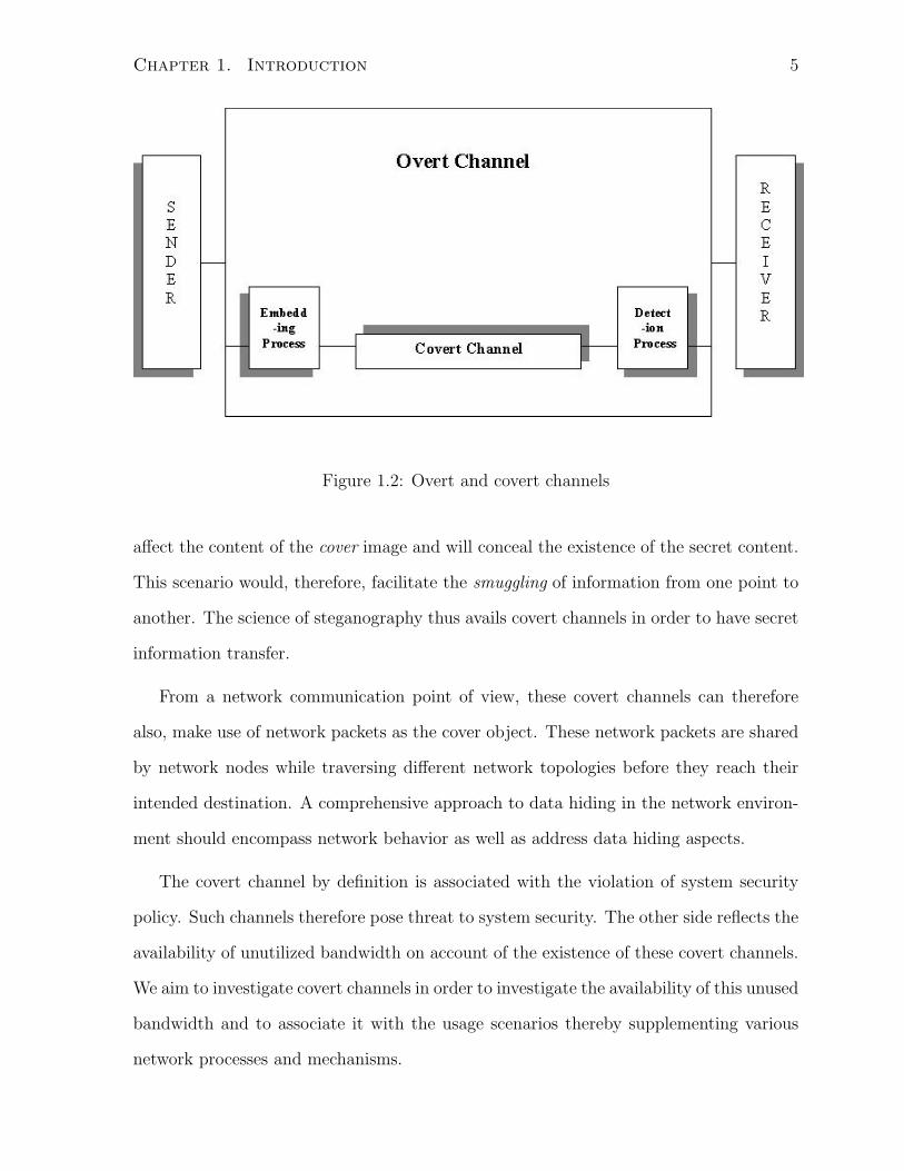
Figure 1.2 below shows the conceptual existence of the covert channel. An overt
channel can be utilized to act as a covert channel by having embedding and detection
processes incorporated at the source and the receiver, respectively. By definition, the
existence of covert channels must be non-detectable.
Covert channels can be regarded as one of the main sub-disciplines of data hiding. In
data hiding, the two communicating parties are allowed to communicate with each other
based on the security policy of the system while exploiting the features as associated with
covert channel definition; there is piggy-backing of undetectable data on the legitimate
content. This led to an emerging discipline, steganography, which is the Greek for covered
writing. Steganography is therefore about concealing the existence of the message when
secret information is hidden into an innocent cover data. The simplest example usually
referred to, is the usage of the low order two or three bits of each pixel in a digital image
for the secret data to be communicated. The last two or three bits are less likely to
Chapter 1. Introduction 5
Figure 1.2: Overt and covert channels
affect the content of the cover image and will conceal the existence of the secret content.
This scenario would, therefore, facilitate the smuggling of information from one point to
another. The science of steganography thus avails covert channels in order to have secret
information transfer.
From a network communication point of view, these covert channels can therefore
also, make use of network packets as the cover object. These network packets are shared
by network nodes while traversing different network topologies before they reach their
intended destination. A comprehensive approach to data hiding in the network environ-
ment should encompass network behavior as well as address data hiding aspects.
The covert channel by definition is associated with the violation of system security
policy. Such channels therefore pose threat to system security. The other side reflects the
availability of unutilized bandwidth on account of the existence of these covert channels.
We aim to investigate covert channels in order to investigate the availability of this unused
bandwidth and to associate it with the usage scenarios thereby supplementing various
network processes and mechanisms.

Chapter 1. Introduction 6
1.3 TCP/IP Protocol Suite
Protocols provide the syntactic and semantic rules for communication. They
contain the details of message formats, describe how a computer responds
when a message arrives and specify how a computer handles errors or other
abnormal conditions. Most importantly, they facilitate computer commu-
nication independent of any particular network hardware. Protocols are to
communication what algorithms are to computation. [8]
The TCP/IP protocol suite has been designed to provide a simple, open communica-
tion infrastructure. The goal is to maximize communication performance, connectedness
and collaboration. The suite is a hierarchical protocol made up of interactive modules
each of which provides a specific functionality. It is based on conventional packet switch-
ing technology, but is independent of any particular vendor’s hardware. The significance
of this protocol suite lies in its independence from the network topology and its universal
interconnection; any pair of computers can communicate if they both employ TCP/IP
protocols.
The protocol suite provides three sets of services: application-oriented, reliable and
connectionless. Reliable and connectionless information transfer fall under the class of
network level services whereas application-oriented mechanisms are categorized as appli-
cation level services. These latter services provide a set of application programs that
use the underlying network to carry out useful communication tasks. The most popular
Internet application services include: World Wide Web, electronic mail, file transfer and
remote login.
Connectionless services involve the best-effort delivery of network packets, which is
the most fundamental internet service. This entails that a TCP/IP-employed network
routes a message from one computer to another based on address information carried
in the data. Here, the packet delivery is not guaranteed to the intended destination.

Chapter 1. Introduction 7
The Internet Protocol (IP), residing on the Internet layer, provides such connectionless
services.
Reliable transport services allow an application on one computer to establish a con-
nection with another on a different computer to transfer large volumes of data via a
seemingly direct hardware connection. Therefore reliable transport services ensure packet
delivery to the intended destination against transmission errors, lost packets and failure
of intermediate nodes along the path between the sender and the receiver. The Trans-
mission Control Protocol (TCP) offers these reliable delivery services and forms part of
the transport layer of the protocol suite.
Application Layer FTP, Telnet, DNS, SMTP
Transport Layer TCP, UDP
Internet Layer IP, ICMP, IGMP
Data Link Layer Network Interface and Device Drivers
Table 1.1: The TCP/IP protocol stack showing general protocols on the respective layers
Table 1.1 shows the TCP/IP protocol suite as a stack of protocols (not all the protocols
are shown) residing within four different conceptual layers of TCP/IP software.
At the top of the hierarchy is the application layer that serves as a window for asso-
ciated programs to access network level services. The next two layers perform the main
functions of the protocol stack. The transport layer is responsible for the reliable and
transparent transfer of data between the two end points; the TCP and User Datagram
Protocol (UDP) reside on the transport layer. The network layer mainly performs the
addressing and routing operations necessary to move data through the network; the IP,
Internet Control Message Protocol (ICMP) and Internet Group Management Protocol
(IGMP) lie on the Internet layer of the protocol stack. The data link layer is responsi-
ble for communicating with the actual network hardware (e.g., the Ethernet card); this
is where device drivers for different interfaces reside. Our focus with respect to covert

Chapter 1. Introduction 8
channel identification and analysis is on the protocols on the second and the third layers,
as they perform the most integral functions of the TCP/IP protocol suite.
1.4 Problem Formulation
1.4.1 Motivation
During the development of TCP/IP, little attention was paid to traditional security as-
pects. For instance, the protocols governing TCP/IP are not designed to ensure integrity
of the messages being transferred, nor to authenticate the originating source of the trans-
mitted packet. A formal model of TCP/IP networks in light of some well-known security
threats is presented in [9]. This model characterizes the topology of TCP/IP security
to enable better understanding of the inherent vulnerabilities. Similarly, [10] points out
serious security flaws in the TCP/IP protocol suite with details on a variety of attacks.
Besides identifying threats, it also presents broad-spectrum defenses such as encryption.
In some specific cases, introducing redundancy into the protocol specification can, in
part, help protect against security vulnerabilities. In addition, there are multiple inter-
pretations of the TCP/IP design strategies that require the natural use of redundancy.
However, as discussed in [11], redundancy in communication elements is a key enabler
for covert transmission. Thus, in addition to being open to direct security threats, the
TCP/IP protocol suite is also susceptible to covert communications in any of its standard
implementations.
Our work addresses the issue of the existence of covert channels within a TCP/IP
environment by presenting various data hiding scenarios. Covert channels are considered
as potential threats to system security. However, we consider these as unused bandwidth
and accordingly suggest usage scenarios. Covert channels can be made to act as catalyst
in various security related application usages.

Chapter 1. Introduction 9
1.4.2 Framework
In our framework, we assume that Alice and Bob, the famous analogy in cryptology,
representing points A and B in an information transfer scenarios, employ data hiding
involving the TCP/IP protocol suite to covertly communicate information. The covert
message Ck traverses generally a non-ideal channel. This non-ideal channel is charac-
terized by an incidental process which affects the covert message Ck. Keeping in view a
model of the channel, Bob deciphers the covert message thereby making secret commu-
nication possible in the TCP/IP environment.
The basic framework is shown in Figure 1.3 and is explained as follows:
Figure 1.3: The general covert channel framework in TCP/IP
• Cover object is the network packet Pk. The cover object is the data used to mask
or conceal the covert information
• The goal of our data hiding is to produce a stego-network packet Sk generated by
the stego-algorithm. Alice covertly communicates the information Ck to Bob by

Chapter 1. Introduction 10
passing data through the stego network packet. She first produces this packet Sk
(from the original packet Pk and Ck) which is transferred to Bob.
• There exists the possibility of a secret key known only to Alice and Bob for reasons
of security.
• As mentioned earlier, the transmission process is modelled as a non-ideal channel
representing the incidental processing on the stego network packet that affects the
covert information flow to produce S∗k . From the network communications per-
spective, this processing can introduce position error(s) in the sequence of network
packets, thereby affecting the covert message, C∗k .
• Moreover, the same stego network packet, Sk, may be required to pass through
an intermediate node (or multiple intermediate nodes) in order to ultimately reach
Bob. As per our definition, the covert channel must not be detected by these
intermediate nodes. In other words, in order to be non-detectable, any intermediate
node finds no difference between Pk and Sk when processing the packet.
• At the intermediate node, a stego network packet, Sk may be dropped due to the
non-availability of buffer capacity. However, this possibility is assumed to be non-
existent in our analysis of the proposed algorithms. We are focussing towards that
network traffic which is most unlikely to be dropped due to buffer unavailability.
Such a condition is possible as we have QoS mechanisms through which network
traffic can be categorized as a preferred class. In addition, we assume there is a
remote possibility that the same stego network packet is corrupted during trans-
mission and consequently be dropped by the data link layer mechanisms.
• If the packet Sk reaches Bob, an extraction/detection algorithm is applied to the
stego packet to estimate the covert information; the extracted covert information
which may possibly be affected is denoted as C∗k .

Chapter 1. Introduction 11
In the next chapter, we review some previous work in the area of data hiding in com-
munication networks. Many of the scenarios fit a part of the basic framework presented
in Figure 1.3

Chapter 2
Previous Work and Thesis
Contribution
2.1 Existing Research in Covert Channels in Com-
munication Networks
2.1.1 Covert Channels in LAN Environment
Girling [12] first analyzes covert channels in a network environment. His work focuses on
local area networks (LANs) in which three obvious covert channels (two storage channels
and one timing channel) are identified. This demonstrates the real examples of the band-
width possibilities for simple covert channels in LANs. For a specific LAN environment,
the author introduced the notion of a wiretapper who monitors the activities of a specific
transmitter on LAN. The covertly communicating parties are the transmitter and the
wiretapper. The covert information, according to Girling, can be communicated through
any of the following obvious ways:
1. By observing the addresses as approached by the transmitter. If total number of
addresses, a sender can approach is 16, then there is a possibility of secret commu-
12

Chapter 2. Previous Work and Thesis Contribution 13
nication having 4 bits for the secret message. The author termed this possibility
as covert storage channel as it depends on what is sent (i.e. which address is
approached by the sender)
2. In the same way, the other obvious storage covert channel would depend on the size
of the frame sent by the sender. For the 256 possible sizes, the amount of covert
information deciphered from one size of the frame would be of 8 bits. Again this
scenario was termed as the covert storage channel.
3. The third scenario presented is pertaining to the existence of covert timing chan-
nel. The time between the successive sends can be observed by the wiretapper to
decipher for instance “0” for the odd time difference and “1” for the even time differ-
ence. The scenario transmits covert information through a “when-is-sent” strategy
therefore termed as the timing covert channel.
The time to transmit a block of data is calculated as a function of software processing
time, network speed, network block sizes and protocol overhead. Assuming blocks of
various sizes are transmitted on the LAN, the software overhead is computed on average
and novel time evaluation is used to estimate the bandwidth (capacity) of the covert
channel. Furthermore, solutions for reducing the bandwidth of covert channels are also
presented. The work paves the way for future research.
In particular, [12] does not take into account the effect of the existence of covert
channels on the overall network performance.
2.1.2 Covert Channels in LAN Protocols
In [13], Wolf presents results that can be regarded as a logical extension of [12], but
applied to LAN protocols. Wolf establishes the fact that encryption, the basic mechanism
of LAN security, cannot ensure the proper blocking of unauthorized information via covert
channels. The work points to the unused bandwidth possible for covert transmission in

Chapter 2. Previous Work and Thesis Contribution 14
most commonly used LAN architecture standards such as IEEE 802.2, 802.3, 802.4, and
802.5. The focus is on LAN implementations opposed to the architecture itself. The
work implies that covert channels can be expected in every system in which resources are
shared. It also highlights the relationship between covert storage channels and protocol
format, and the link between covert timing channels and protocol procedure elements
taking into account the frame layouts of the LAN protocols. Covert storage channels
utilize the reserved fields, pad fields and undefined fields of the frames.
The fields identified, as means to covertly send information, can easily be detected
through the implementation of automated mechanisms. Such mechanisms only monitor
such fields, which would discard such frames utilizing these fields irrespective of their
purpose.
2.1.3 Data Hiding in OSI Model
In [11], Handel and Sanford take a broader perspective and focus on covert channels
within the general design of network communication protocols. They employ the OSI
(Open System Interconnection) network model as a basis for their development in which
they characterize system elements having potential to be used for data hiding. The
adopted approach has advantages over [12]and [13] because standards opposed to specific
network environments or architectures are considered. Foolproof steganographic schemes
are not devised. Rather, basic principles for data hiding in each of the seven OSI layers
are established. Besides suggesting the use of the reserved fields of protocol headers
(that are easily detectible) at higher network layers, Handel and Sanford also propose
the possibility of timing channels involving CSMA/CD manipulation at the physical
layer. The work identifies covert channel figures of merit such as
• Detectability; covert channel must be measurable by the intended recipient only.
• Indistinguishability; covert channel must lack identification; must appear as overt

Chapter 2. Previous Work and Thesis Contribution 15
channel.
• Bandwidth; number of data hiding bits per channel use.
Moreover the properties of system elements which could likely be the containers for data
hiding process are mentioned as
• Uncertainty
• Redundancy
The covert channel analysis presented here, however, does not consider issues such
as interoperability of these data hiding techniques with other network nodes, covert
channel capacity estimation, effects of data hiding on the network in terms of complexity
and compatibility. Moreover, the generality of the techniques cannot be fully justified in
practice since the OSI model does not exist per se in functional systems.
2.1.4 Covert Channels in TCP/IP Protocol Suite
A more specific approach is adopted by Rowland [14]. Focusing on the IP and TCP head-
ers of TCP/IP protocol suite, Rowland devises proper encoding and decoding techniques
by utilizing the IP identification field, the TCP initial sequence number and acknowledge
sequence number fields. These techniques are implemented in a simple utility written for
Linux systems running version 2.0 kernels. Rowland simply provides a proof-of-concept
of the existence as well as the exploitation of covert channels in TCP/IP protocol suite.
This work can, thus, be regarded as a practical breakthrough in this research area. The
adopted encoding and decoding techniques are more pragmatic as compared to previ-
ously proposed work. These techniques are analyzed considering security mechanisms
like firewall and network address translation.
However, the non-detectability of these covert communication techniques is question-
able. For instance, a case where sequence number field of the TCP header is manipu-
lated, the encoding scheme is adopted such that every time the same alphabet is covertly

Chapter 2. Previous Work and Thesis Contribution 16
communicated, it is encoded with the same sequence number. Moreover, the usage of
sequence number field as well as the acknowledgement field can not be made specific to
the ASCII coding of the English language alphabet as proposed, since both fields take in
to account the sent and the receipt of data bytes pertaining to specific network packet(s).
2.1.5 Internet Steganography
Katzenbeisser and Petitcolas [15] have also observed the potential for data hiding in the
TCP/IP protocol suite. The significance of using of TCP/IP stems from the sheer volume
of secret communication that can be realized since TCP/IP packets are used to transport
thousands of Internet packets with each overt communication link. Katzenbeisser and
Petitcolas use the term Internet steganography for this potential scenario and indicate that
the ongoing research work includes the embedding, recovering and detecting information
in TCP/IP packet headers.
2.1.6 Covert Channel Analysis in Networks so far
The research publications discussed above:
1. Identify the existence of covert channels in a network environment.
2. Point to devising satisfactory techniques for embedding and extraction processes
at the source and destination, respectively.
3. Do not consider the affect of employing covert communications on the overt com-
munication network as a whole.
These publications, though related with networks, address the data hiding processes
as isolated cases. These research contributions therefore, do not explore the existence of
covert channels by considering their effect on the overall network environment.

Chapter 2. Previous Work and Thesis Contribution 17
2.1.7 Additional Information in Network Flows
As a part of our research in this thesis, we propose to make use of potential covert
channels in an effective way. We suggest to avail these covert channels by associating
value-added information in the network packets (within either of the TCP or IP headers)
so that covert links can have some supplementary value to existing network processes or
security mechanisms.
Ackermann et al. [16] presents a similar concept, which requires the deviation of the
network architecture from a strict layered approach. Instead of having specific header
information available to only a specific layer, in order to route, filter, interpret or process
data, the accessibility of some additional information can ease certain network processes
like QoS routing functions in network nodes. The nature of the additional information
is defined to be user- or application-specific. Methods of obtaining such information are
mentioned. The IP header is proposed as one of the potential packet-marking placement
areas.
However, the success of placing the additional information in either the IP header
or the MAC (OSI layer 2) header is not fully explored. It is beyond the scope of [16]
to investigate the appropriate location within the packets for data hiding, nor consider
how this information can be encoded/decoded by the sender/receiver or be utilized by
the intermediate nodes. Reference [16] therefore focuses on the network communication
aspect of the data hiding process.
2.2 Contributions of this Thesis
The contributions of this thesis include:
1. the identification of covert storage channels in popular transport and network layer
protocols such as TCP, IGMP, and ICMP.

Chapter 2. Previous Work and Thesis Contribution 18
2. the novel introduction of four storage channels in the IPv4 format header.
3. the design of a new data hiding scheme based on packet ordering under ideal and
non-ideal network conditions.
4. the presentation of possible application scenarios of data hiding in TCP/IP for
supplementing various security related processes and enhanced network security
architecture (IPSec).
5. the survey of the area of steganography in networks by bridging the areas of data
hiding (traditionally studied for multimedia at the application layer), communica-
tions network protocols and network security.
The first three contributions are practical and focus on feasibility of the approaches.
The last two contributions provide novel vision and perspective to the overall work.
2.2.1 The Complete Picture
In this thesis, we attempt to provide a more comprehensive scenario.
1. This work can be considered, in part, a logical extension to [11] and [13] in terms of
covert channel identification. Covert storage channels in the transport and network
layer protocols are investigated by adopting more specific approaches than simply
employing the reserved or unused fields in packet headers. The proposed data
hiding scenarios are more practical since techniques used, are based on redundancies
and multiple interpretations of process strategies of the Internet protocol. This
makes these scenarios non-detectable to various automated security mechanisms
and intermediate nodes.
2. This research also expands on the work presented in [14] as more specified encoding
and decoding techniques are suggested keeping in view their interoperability with
network security mechanisms such as firewalls and routers. These mechanisms

Chapter 2. Previous Work and Thesis Contribution 19
would treat the stego network packet, Sk as the network packet, Pk, thereby letting
the same to pass through these without being detected as covert information carrier.
The header fields selected for data hiding process seem more appropriate due to
the flexibility of sending covert information without interfering with the standard
processes. Reference [14] uses sequence number field and acknowledgement number
field of TCP which follow the number of bytes sent and acknowledged. These fields
are therefore inflexible to send a sequence of encoded covert data. The motivation
of utilizing header fields in this work is elaborated in subsequent sections of the
data hiding scenarios in chapter 3 and 4.
3. This work can also be considered a supplement to [12], as we estimate the channel
bandwidth (capacity) of one of the approaches along similar lines; the essential
difference is the medium used for data hiding; we propose covert channels one layer
above the data link layer.
4. Our proposed algorithm based on packet sorting is also evaluated using figures
of merit like interoperability, compatibility, and complexity. Furthermore, for re-
sorting process, a best estimation technique is suggested. This technique would
facilitate receiving party to decipher the covert message by detecting the sent se-
quence of packet since IP layer does not guarantee sequenced delivery of packets at
the destination.
5. In addition, we present various application scenarios by utilizing the concepts pro-
posed by Ackermann et al. [16].
6. A more indistinguishable and non-detectable data hiding environment is also pre-
sented in IPSec by combining the two proposed approaches.
Points 1 and 2 deal with improved data hiding schemes as compared to existing
research. These points also take into account the network effect on Sk covering network

Chapter 2. Previous Work and Thesis Contribution 20
communication perspective. Point 3 identifies storage covert channel capacity (number
of covert bits per frame) estimation at Internet layer. Point 4 addresses the effect of data
hiding process on the network by taking into account various network-related figures
of merit. The use of data hiding processes is mentioned in point 5. This use provides
applications in network environment. Same as the point 6 mentioning the combination of
the two approaches for a better network related data hiding scenario. This encompasses
aspects of improved data hiding processes, consideration of their effect on network and
development of application scenarios especially for network security, thereby completing
the overall picture.
2.2.2 The New Dimension of Security Analysis
The current research trend involving the TCP/IP protocol suite focuses on performance
issues as well as the associated security threats and defenses [9],[10] and [17]. From this
perspective, we aim to provide a new dimension to existing security analysis. Covert
channel scenarios are proposed utilizing packet headers and sorting of packet sequences.
Packet sorting is employed within the IP Sec framework, which opens the door for the
interaction between steganography and traditional network security. The importance of
IP Sec is evident from the fact that IPv6 has mandatory security services of authentication
and confidentiality that can be made possible through the use of the Authentication
Header (AH) and Encapsulating Security Payload (ESP) protocols of IP Sec (see appendix
for header format). An enhanced security mechanism is envisioned with the integration of
stego principles and existing network security architecture. Various application scenarios
are presented to further explain the novelty of this concept. Moreover, the application of
such stego principles at the network layer can facilitate security mechanisms in the layer
3 nodes like routers and firewalls.

Chapter 3
Packet Header Manipulation
3.1 Covert Channels in Transport and Network Lay-
ers
This section contains a general investigation of various protocols on the transport and
network layers. The list of protocols that are evaluated for possible use in covert com-
munications include the TCP (Transmission Control Protocol), IGMP (Internet Group
Management Protocol), ICMP (Internet Control Message Protocol) and Internet Proto-
col (IP). This does not serve to provide an exhaustive look at possible covert channels
but attempts to prove existence of simple storage channels, in mentioned protocols, that
might be used later (future research) possibly.
3.1.1 TCP (Transmission Control Protocol)
At the transport layer, TCP is intended to provide a reliable process-to-process communi-
cation service in a multi-network environment. TCP is, therefore, a connection-oriented
and reliable transport protocol. The header of the TCP protocol is shown in Figure 3.1.
It has a 6-bit field labelled as code bits (URG, ACK, PSH, RST, SYN, FIN). These
bits determine the purpose and contents of the TCP segment. These six bits tell a network
21

Chapter 3. Packet Header Manipulation 22
Figure 3.1: The TCP header
node how to interpret other fields in the header. There are 64 possible combinations for
these six bits, out of which 29 combinations are considered to be valid as per the rules set
forth by the protocol [18]. For the covert channel identification, the intent is to explore
any redundancy condition within these possible code bit combinations. Most of the TCP
segments have an ACK bit set (i.e., the value of the ACK bit is 1) because of the full
duplex nature of the connection between two hosts. This allows data piggybacking since
acknowledgements can be sent with data. One of the redundancy conditions is shown in
Table 3.1 below:
URG ACK PSH RST SYN FIN
0 1 1 0 0 1
Table 3.1: The TCP flags field. A possible redundancy condition
Table 3.1 represents one of the valid combinations of the 6-bit code fields. It can be
interpreted as follows: One of the ends of the virtual connection intends to finish the

Chapter 3. Packet Header Manipulation 23
connection (FIN =1) from its end and at the same time it sends an acknowledgment
(ACK is set). The push flag is also set as the same end requests the receiving transport
layer to push the data to its respective application layer immediately. Since the URG
bit is not set, the Urgent pointer field (16 bit) of the TCP header, shown in Figure 3.1,
becomes redundant and therefore can be used to have a storage covert channel.
Likewise, redundancy conditions exist for all those possible cases wherein the URG
bit is not set thereby making the urgent pointer field redundant. The SYN bit set can
also have possible combinations either with the ACK bit set or the URG/PSH (not both
at the same time) set to 1. Therefore, the remaining bits are meaningless for the protocol
enabling covert data transmission possibilities through TCP header.
3.1.2 IGMP (Internet Group Management Protocol)
IP multicasting (one-to-many communication) follows the paradigm of allowing trans-
mission to a subset of host computers, but it generalizes the concept to allow the subset
to spread across arbitrary physical networks throughout the Internet. A given subset is,
therefore, known as multicast group. Multicast routers and hosts that implement multi-
cast must use IGMP to communicate group membership information. The two message
phases are report messages (host to router - joining a group, membership continuation,
leaving the group) and query messages (router to host - monitoring the group).
IGMP is encapsulated in an IP datagram for transmission. Here the IP destination
address is the multicast address. A specific nomenclature of the IP datagram as per RFC
2236 (IGMP v2 message with router alert option), can be defined keeping in view the
following values of IPv4 header fields:
• Version = 4;
• IHL = 6 words;
• Total length = 32 octets;

Chapter 3. Packet Header Manipulation 24
• TTL = 1 (requires one hop only);
• Protocol = 2;
• Router alert option (An IP option that causes each intermediate router to examine
a datagram even if the datagram is not destined to the router);
• Fragmentation may (DF bit is zero) or may not (DF bit is set) be allowed
The IGMPv2 can have the following two types of messages:
1. Membership report message and leave group message - host to router
2. Membership query message - router to host.
Based on the nomenclature defined above and the types of IGMP messages, following
IP datagrams are possible:
a Host to Router; Membership report, refer Table 3.2 and leave group messages; Frag-
mentation allowed
b Host to Router; Membership report and leave group messages; Fragmentation not
allowed
c Router to Host; Membership query messages; Fragmentation allowed
d Router to Host; Membership query messages; Fragmentation not allowed
By having a 16-bit arrangement of the complete IP datagram, a 16X16 matrix is
obtained. The intent is to use the unused bits (8 bits; actually set to zero by sender and
ignored by receiver (for report messages - host to router) and 16 bits; actually set to zero
by the sender (for query messages - router to host) in order to have some secret data
transferred between host to router and router to hosts. This can be combined with other
fixed values of other fields as defined in the nomenclature above.

Chapter 3. Packet Header Manipulation 25
4-bit Ver. 4-bit IHL 8-bit TOS 16-bit Tot. Len.
0100 0110 XXXXXXUU 0000000000100000
16-bit Ident. 3-bit flags 13-bit Frag.Off.
XXXXXXXXXXXXXXXX UOX XXXXXXXXXXXXX
8-bit TTL 8-bit Protocol 16-bit Checksum
00000001 00000010 XXXXXXXXXXXXXXXX
32-bit Source Address
XXXXXXXXXXXXXXXXXXXXXXXXXXXXXXXX
32-bit Destination Address
XXXXXXXXXXXXXXXXXXXXXXXXXXXXXXXX
8-bit type 8-bit Length 16-bit Data
10010100 00000100 0000000000000000
8-bit type 8-bit Max.Resp. Time 16-bit Checksum
00010000 UUUUUUUU XXXXXXXXXXXXXXXX
32-bit Source Address
XXXXXXXXXXXXXXXXXXXXXXXXXXXXXXXX
Table 3.2: IGMP encapsulated in IPv4 header with router alert option; host to router;
membership report message
Therefore, by considering 16X16 matrix’ rows 2,5,11,12,13 for report messages (frag-
mentation allowed) table 3.3 refers, rows 2,4,5,11,12,13 for report messages (fragmenta-
tion not allowed), rows 2,5,11,12,15,16 for query messages (fragmentation allowed) and
for query message (fragmentation not allowed)rows 2,4,5,11,12,15,16 of the 16X16 ma-
trix, we can attain possible covert communication scenarios through proper embedding
/ extraction processes at the two communicating ends, respectively.

Chapter 3. Packet Header Manipulation 26
Row # 1 2 3 4 5 6 7 8 9 10 11 12 13 14 15 16
2 0 0 0 0 0 0 0 0 0 0 1 0 0 0 0 0
5 0 0 0 0 0 0 0 1 0 0 0 0 0 0 1 0
11 1 0 0 1 0 1 0 0 0 0 0 0 0 1 0 0
12 0 0 0 0 0 0 0 0 0 0 0 0 0 0 0 0
13 0 0 0 1 0 0 0 0 U U U U U U U U
Table 3.3: Respective rows of 16X16 matrix; report message
3.1.3 ICMP (Internet Control Message Protocol)
The ICMP is the mechanism used by hosts or routers to send notification of IP datagram
problems back to the sender. ICMP packets are encapsulated inside of IP datagrams.
The ICMP sends query and error reporting messages. With query messages, ICMP can
also diagnose some network problems. In this class of ICMP messages, a node sends a
message that is answered in a specific format by the destination node. The details of
ICMP can be found in [19]. The following highlights examples of covert storage channels.
ICMP echo request and ICMP echo reply messages
The Optional data field allows having a variable length data to be returned to the sender.
IP options like router alert, record route and time stamp can be used encapsulating
ICMP echo request message. This provides a possibility to have covert channel between
the communicating parties. Moreover, network devices usually do not filter the contents
of ICMP echo traffic if ICMP echo traffic is allowed.
ICMP address mask request
The ICMP address mask request is meant from host to the specific router on the LAN
or broadcast message to all the routers on the LAN. The request is filled with zeros in

Chapter 3. Packet Header Manipulation 27
the 32-bit address mask field. This can be used to have covert communication from host
to router(s) on the same LAN.
Router solicitation
A host sends a solicitation after booting to request that routers on the local net imme-
diately respond with an ICMP message router advertisement. It has a 32 bit reserved
word. These reserved bits can be made to use for covert communication for a specific
scenario.
3.2 Data Hiding through Packet Header Manipula-
tion
3.2.1 Data Hiding in IPv4 header: General Considerations
The possibilities of covert channels in transport and Internet layer protocols are identi-
fied and briefly explained in chapter 3. This section specifically deals with data hiding
possibilities in the IPv4 header. Four scenarios are discussed that make use of flags and
identification fields of the header. The layered architecture requires the IP datagram to
encapsulate data received from the transport layer. Similarly, IP datagram headers en-
capsulate ICMP messages as well as IGMP’s report and query messages. Covert channels
in the IPv4 header can, therefore also, be associated with those identified in the TCP,
ICMP or IGMP headers. This facilitates an increased amount of covert information tied
with any of these messages. Therefore, flexibility of associating additional information
with ICMP, IGMP and TCP traffic through IP header, is achieved, once covert channels
are explored in IP header. As depicted earlier, redundancies and multiple interpretations
of the design strategy give rise to possible covert channels, which are exploited in the
following IPv4 header manipulation schemes.

Chapter 3. Packet Header Manipulation 28
In identifying covert channels, one could argue that it depends on the fashion in
which the specific TCP/IP software is implemented in a specific environment especially
with regards to the user interface. We address this by considering only those functional
interfaces that are required in all IP implementations. Some of these interfaces are
well stated in [20]. Another factor is the design considerations on which a TCP/IP
implementation is based upon. One of the design strategies, the packet fragmentation
strategy, explained below, is followed in the identification of covert channels in the IPv4
header.
Setting
As per RCF 791 elaborating on IP [20],
the implementation of the protocol must be robust. In general, an implemen-
tation must be conservative in its sending behavior and liberal in its receiving
behavior i.e. it must be careful to send well-formed datagrams but must ac-
cept any datagram that it can interpret.
Fragmentation of an Internet datagram is necessary when it originates from a network
that allows a large packet size and must traverse a network that limits these datagrams to
a smaller size to reach the destination. Reference [20] also states that the fragmentation
strategy of the Internet protocol is designed so that an un-fragmented datagram has all
zero fragmentation information i.e. MF = 0 (one of the three flags fields of IP header,
first bit is Reserved, second bit is DF, i.e. Do not Fragment and the third bit is MF i.e.
More Fragment) and fragment offset = 0 (13 bit IP header field). Refer Figure 3.2 for the
respective fields of IPv4 header. It implies that the fragmentation policy does not put
forth any condition on the value of identification field, which carries the identifying value
assigned by the sender to aid in assembling the fragments of a datagram. So the design
aspect of the Internet Protocol makes identification field of the IP header independent
from the process of fragmentation. Here it would be appropriate to mention that the

Chapter 3. Packet Header Manipulation 29
sender chooses the identifier (value in the identification field of the IP header) to be
unique for the specific source - destination pair and protocol for the time the datagram
(or any fragment of it) could be alive in the Internet.
Figure 3.2: The IP header
The above discussion implies the following:
1. For all un-fragmented datagrams, [20] requires that MF (More Fragment) and frag-
ment offset must be zero.
2. The identification field though associated with fragmentation process is not bound
to carry any specific range of value for the un-fragmented datagrams. It requires
only a unique value assigned to the identification field for the specific source, des-
tination and protocol fields.
Point 1 gives rise to a redundancy condition i.e. DF (Do not Fragment) can carry
either “0” or “1” subject to the knowledge of the maximum size of the datagram that
could be sent without fragmenting the same. This aspect is exploited in data hiding
scenario 1. Data hiding scenarios 3 and 4 are based on the generation of identification
field utilizing point 2. Data hiding scenario 2 avails both the points and develops a
one-to-many secret communication environment.

Chapter 3. Packet Header Manipulation 30
3.2.2 Data Hiding Scenario 1
Consider two workstations on the same network having users Alice and Bob. Both decide
to have a covert communication by employing protocol suite of the network. They are
well aware of the fact that the network administrator is very security cautious and the
TCP/IP software is configured properly as per the security policy of the organization.
Alice and Bob have knowledge of the MTU (maximum transmission unit) 1 of their
network and they are aware of the fragmentation strategy, which follow the standard
design considerations of IP [20].
Figure 3.3: The block diagram of data hiding scenario 1
Figure 3.3 shows the block diagram of scenario 1 in context of the framework presented
in Figure 1.3 of Chapter 1. The embedding algorithm avails the fragmentation strategy
of the Internet protocol and DF bit is used to send covert bit to Bob. Bob accordingly
reads the DF bit and gets the covert message from Alice sitting on the same network.
Keeping in view the design strategy of fragmentation process, the following datagrams
(only those fields are shown, which are of interest) of IPv4 header bear the same mean-
ing in terms of overt communication. In each of the cases, covert data is imperceptible
1The MTU can either be known through social engineering or estimated by sending test datagramsto find out whether they are segmented or not

Chapter 3. Packet Header Manipulation 31
because of treating the stego network packet Sk as network packet, Pk by the network
or the network administrator. Here two sets of datagrams are shown: suspicious and
non-suspicious. Suspicious are those that can catch the eye of the network administrator
as possessing abnormal data or message as compared to normal packets. Non-suspicious
would be those that are engineered well in order to deceive the network monitoring auto-
mated devices. From the covert communication point of view, non-suspicious datagrams
would be termed as appropriate for data hiding process.
Datagram #1
Complete datagram; minimal data; small size datagram; fragmentation not allowed
since DF bit is set; Suspicious since the size is too small and even then , it is instructed,
not to fragment it. Table 3.4 refers.
Datagram # 16-bit Id. field 3-bit Flags 13-bit Frag.Offset 16-bit Total Length
1 XXX..XX 010 000...0 21
Table 3.4: Suspicious datagram header
Datagram #2
Complete datagram; moderate size; fragmentation not allowed since DF bit is set;
Appropriate for data hiding. Table 3.5 refers.
Datagram # 16-bit Id. field 3-bit Flags 13-bit Frag.Offset 16-bit Total Length
2 XXX..XX 010 000...0 472
Table 3.5: Datagram header appropriate for data hiding
Datagram #3
Complete datagram; moderate size; fragmentation is possible, since DF bit is not
set; but fragmentation will not take place since both Alice and Bob know the MTU of
their network and they have agreed to send the datagram of size smaller than MTU;

Chapter 3. Packet Header Manipulation 32
Appropriate for data hiding. Table 3.6 refers.
Datagram # 16-bit Id. field 3-bit Flags 13-bit Frag.Offset 16-bit Total Length
3 XXX..XX 000 000...0 472
Table 3.6: Datagram header appropriate for data hiding
Datagrams 2 and 3 in Tables 3.5 and 3.6, can therefore communicate “1” and “0”
respectively to Bob. So DF bit (middle bit of the 3 bit flags field) can either be set to one
or to zero whenever “1” or “0” is required to be covertly communicated. The constraint
is however, required to be met i.e. prior knowledge of MTU. The network administrator
who is keeping a cautious eye would not have the slightest indication that if Alice and
Bob make this communication not so frequently. Thus, this scenario presents a simple
data-hiding scheme by utilizing the redundant condition identified in the IPv4 header.
3.2.3 Data Hiding Scenario 2
In continuation with Scenario 1, we consider the other IPv4 field, the identification field.
Datagrams 2 and 3 of Tables 3.5 and 3.6 enable Alice and Bob to communicate covertly.
The identifier value could also be associated with this covert communication. Thus, for a
single datagram communicating either “1” or “0” through the respective datagrams 2 and
3, more information could also be sent through the identification field; this can further add
to the information being communicated through ”1” or ”0.” The only rule to be followed
is to maintain the uniqueness of the identification value for each respective datagram
specific to sender-destination pair and protocol field. So each datagram could represent
unique multiple bit covert information if Alice and Bob agree to use the combination of
the DF bit with identification field. The fact that the DF bit and the identification field
are independent also implies that this scenario entails multiple covert channels within a
single packet. The covert information can easily be decoupled from the respective fields

Chapter 3. Packet Header Manipulation 33
of the header through proper algorithms.
The conceptual block diagram of scenario 2 can be shown in Figure 3.4. The embed-
ding algorithm makes use of the DF bit of the flags field and identification field for the
covert transfer of information, from Alice to Bob. Accordingly, Bob deciphers the covert
message from the respective fields through a proper decoding algorithm.
Figure 3.4: The block diagram of data hiding scenario 2
Moreover, the 16-bit identification field (655, 536 unique values) facilitates hosts to
use the unique identifiers independent of destination encourages Alice and Bob to have
more parties involved in secret communications. Alice can send an engineered datagram
to Bob as well as Carol and Dave, representing points C and D for secret communication,
having the same identification value plus the DF bit (either “0” or “1”). Therefore, this
scenario of data hiding facilitates multiple recipients of a single covert message from Alice
i.e. the one-to-many covert communication scenario, provided that they are connected
to the same network and have prior knowledge of MTU.

Chapter 3. Packet Header Manipulation 34
3.2.4 Data Hiding Scenario 3
So far the data hiding schemes are restricted to communicating parties on the same
network and it is also assumed that each party knows the MTU of the transmission
medium involved in the complete network.
Scenario 3 is independent of the prior knowledge of the MTU. It aims to use the iden-
tification field with the consideration that the datagrams generated by communicating
parties must not contain options in the IP header. IP headers without options are usual
for Internet communication and most of the analysis often does not consider these in the
IPv4 header. If the options field is not considered to be present in the IPv4 header, it
would make the length of the header as 5 i.e. 5 words (each word comprises 32 bits)
These two considerations would set the values in the very first two fields (4 bit each) of
IPv4 header as:
1. Version field as 4 (binary equivalent: 0100) and
2. Internet header length field as 5 (binary equivalent: 0101).
This scenario can also be applied to hosts who intend to communicate with each other
covertly across an Internet subject keeping in view the framework as detailed in chapter
1.
In the following two sub-sections, we discuss steganographic encoding and decoding
schemes. It is encouraged to refer to Figure 3.2 for better understanding. This scenario
utilizes the combination of identification field and the version & Internet header length
fields of the IPv4 header. The resulting header format would be appropriate for data
hiding since the network would not be able to detect irregularities in any of the fields.
The network or the network administrator is assumed to be ignorant of the encoding
technique, detailed below. This fact can be justified as numerous automated network
monitoring mechanisms only check the data in the respective fields, not in the combina-
tion. Also the selected fields do not pose any threat to network security as the attention

Chapter 3. Packet Header Manipulation 35
is focussed on IPv4 header fields like source address (IP spoofing), destination address,
total length, and protocol fields [21].
A block diagram of data hiding scenario 3 is shown in Figure 3.5. The embedding
block states the various header fields employed in the scheme. The XOR operator is used
to encode and decode the covert information. Bob extracts the secret information only
by having the prior knowledge of the encoding scheme.
Figure 3.5: The block diagram of data hiding scenario 3
Encoding
Alice needs to do the following at her end:
1. The 4-bit version field and the 4-bit Internet header field are fixed to have values
0100 and 0101 respectively. This would constitute the first 8 bits of the first word of
the IPv4 header as shown in Figure 3.2. Let us denote these bits as [h1, h2,. . . ,h8].
2. The Identification field constitutes the first 16 bits of the second word of the IPv4
header and is denoted as [i1,i2,. . . ,i16]. Consider the first 8 bits of the first and
the second word of the header namely, [h1, h2,. . . ,h8] and [i1,i2,. . . ,i8] respectively.

Chapter 3. Packet Header Manipulation 36
The first 8 bits shall have [h1, h2,. . . ,h8] = 01000101 and the second word 8 bits
[c1,c2,. . . ,c8] can contain the covert data to transmit (say any ASCII character).
This means that c1 is a covert data bit and the 8 bits c1,c2,. . . ,c8 are formed from
il = hl ⊕ cl.
3. Perform bit-wise XOR operation on both first eight bits of first and second word
of the header. Therefore, i∗l = hl ⊕ cl, l = 1, 2,. . . , 8 where ⊕ is the XOR operator.
4. The rest of the 8 bits of the identification field can be generated randomly and
combined with the first eight bits to assure the uniqueness for a specific source-
destination and protocol fields combination. That is, i∗l for l = 9, 10,. . . , 16 is
randomly generated and concatenated to form [i∗1, i∗2,. . . ,i∗16]as the new identification
field for covert communication.
5. The datagram of Table 3.7 , can then be transmitted across the Internet and there
would be no worries if the datagram gets fragmented because at the destination,
reassembling would be done based on the same identification field.
Referring to Table 3.7, letter “A” has ASCII value as 65, the binary equivalent of
which is 01000001. Thus [c1,c2,. . . ,c8]= [01000001].
Therefore
i∗l = hl ⊕ cl , l = 1, 2, ....8
would be
[i∗1,i∗2,. . . ,i
∗8] = [01000101] ⊕ [01000001]
resulting in
[i∗1,i∗2,. . . ,i
∗8]= [00000100]
as the identification field value of Table 3.7.

Chapter 3. Packet Header Manipulation 37
4-bit Ver. 4-bit IHL 8-bit TOS 16-bit Tot. Len.
0100 0101 XXXXXXUU XXXXXXXXXXXXXXX
16-bit Ident. 3-bit flags 13-bit Frag.Off.
0000 0100 RRRRRRRR XXX XXXXXXXXXXXXX
8-bit TTL 8-bit Protocol 16-bit Checksum
XXXXXXXX XXXXXXXX XXXXXXXXXXXXXXXX
32-bit Source Address
XXXXXXXXXXXXXXXXXXXXXXXXXXXXXXXX
32-bit Destination Address
XXXXXXXXXXXXXXXXXXXXXXXXXXXXXXXX
Table 3.7: IPv4 header; identification field manipulation; letter “A” is embedded in the
identification field
Decoding
At the receiving end:
1. Bob obtains the packet with corresponding version & Internet header length fields
bits and the identification field bits
2. He performs the XOR operation to obtain the covert data stream as:
[c1,c2,. . . ,c8]= [h1, h2,. . . ,h8] ⊕ [i∗l ,i∗2,. . . ,i
∗8]
Putting respective bits:
[c1,c2,. . . ,c8]=[01000101]⊕ [00000100]
To get the binary equivalent of ASCII, “A”
[c1,c2,. . . ,c8]=[01000001]

Chapter 3. Packet Header Manipulation 38
Due to the manipulation of identification field, this data-hiding scenario is resistant
to packet filtering firewalls [21]. Moreover the stateful inspection firewalls do not detect
this same scenario because of the randomness introduced in the last eight bits of the
identification field. Also referred to as dynamic packet filtering, stateful inspection is
a firewall architecture that works at the network layer. Unlike static packet filtering,
which examines a packet based on the information in its header, stateful inspection tracks
each connection traversing all interfaces of the firewall and makes sure they are valid. It
examines the content of the packet up through the application layer in order to determine
more about its source and destination. It also monitors the state of the connection and
complies the information in a state table. Besides packet header information criteria, the
filtering decisions are based on the context that has been established by prior packets
passed through the firewall. For this case, this ensures that with low probability i.e. 0.4%
(eight bits of identification field are encoded as per stego algorithm and the rest of the
eight are randomly generated. These random eight bits would ensure the uniqueness of
the encoded data even if the encoded covert letters are similar. The probability of having
the same identification field for the similar data to be covertly sent would therefore be
1256
) no two similar data to be covertly communicated would have the same identification
field value.
3.2.5 Generation of Sequences - Toral Automorphisms
Before explaining the fourth data hiding scenario, a concept of toral automorphisms is
described [22].
Toral Automorphism Systems
Toral Automorphisms are strongly chaotic (mixing) systems [23], which find applications
in digital images these days especially for the embedding of watermarks (copyright pro-
tection). The word chaos has both a general meaning and a scientific meaning. As is

Chapter 3. Packet Header Manipulation 39
usually the case, the general meaning tends to convey little of the strict definition that
scientists and mathematicians apply to the word. The dictionary defines the word chaos
as, a condition or place of total disorder or confusion. What scientists and mathemati-
cians mean by chaos is very much related to the spirit of the dictionary definition stated
above. Systems are chaotic if they:
• are deterministic through description by mathematical rules.
• have mathematical descriptions which are nonlinear in some way.
Considering digital images as a set of pixels which form a two dimensional integer
lattice, toral automorphism systems are characterized by special properties when they
act on such lattices.
A two dimensional Toral automorphism is a spatial transformation of planar regions
which belong in a square two- dimensional area. The main structure in this process is
a 2 × 2 matrix with constant elements representing the toral automorphism mapping
denoted with A. Matrix A is constrained to have
1. elements that belong to the set of positive integers and
2. a determinant of 1.
The latter property ensures the existence of the inverse automorphism represented by
A−1, the inverse matrix.
Thus a point r , having coordinates as x and y, belonging to a specific domain U of
the integer lattice can be subjected to iterated actions by a toral automorphism matrix.
This iterated action forms a dynamical system which can be expressed with a map.
rn+1 = Arn(mod1) (3.1)
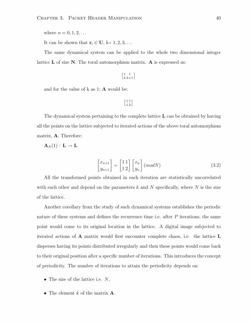
Chapter 3. Packet Header Manipulation 40
where n = 0, 1, 2, . . .
It can be shown that ri ∈ U, i= 1, 2, 3, . . .
The same dynamical system can be applied to the whole two dimensional integer
lattice L of size N. The toral automorphism matrix. A is expressed as:
[1k
1k+1
]
and for the value of k as 1; A would be:
[11
12
]
The dynamical system pertaining to the complete lattice L can be obtained by having
all the points on the lattice subjected to iterated actions of the above toral automorphism
matrix, A. Therefore:
AN(1) : L → L
[xn+1
yn+1
]=
[1
1
1
2
] [xn
yn
](modN) (3.2)
All the transformed points obtained in each iteration are statistically uncorrelated
with each other and depend on the parameters k and N specifically, where N is the size
of the lattice.
Another corollary from the study of such dynamical systems establishes the periodic
nature of these systems and defines the recurrence time i.e. after P iterations, the same
point would come to its original location in the lattice. A digital image subjected to
iterated actions of A matrix would first encounter complete chaos, i.e. the lattice L
disperses having its points distributed irregularly and then these points would come back
to their original position after a specific number of iterations. This introduces the concept
of periodicity. The number of iterations to attain the periodicity depends on:
• The size of the lattice i.e. N ,
• The element k of the matrix A.

Chapter 3. Packet Header Manipulation 41
Mathematically, for any integer lattice L of size N , there is an integer P , P = P (k,N)
such that:
APN(k)r = r(modN), r ∈ L (3.3)
The automorphism as mathematically stated in Equation 3.3 is mixing. It produces a
chaos wherein the points are irregularly distributed and spread all over the lattice. The
digital image would be transformed and a chaotic image is obtained having no relation
with the original image. This state of the digital image follows the definition of chaos
(mixing) as defined from mathematicians and scientists point of view.
From these fundamentals of toral automorphism, the following can be concluded:
1. Size of the lattice, N defines a domain of the lattice which restricts all sorts of
irregularities and chaos within its limits. In equation 3.3, (mod N) performs this
function. Thus all transformation of points would be confined to a specific set,
defined as the size of the two dimensional integer lattice.
2. The element k of the toral automorphism matrix has its role in the iterated actions
of the matrix on each point in the lattice. This element is associated with recurrence
time, P .
3. Recurrence time, P is the number of iterations after which the system comes back
to its original position. Each iteration before the recurrence time has a set of
transformed points in which all the points are highly uncorrelated with each other;
thus occupy unique locations within the lattice.
Generation of Sequence; Controlled but Irregular
From the chaotic transformation of digital images and phenomenon of periodicity of this
transformation, when an integer lattice is subjected to iterated actions by Equation 3.3,
a structure of sequence generation is devised. The details of this structure are as follows:

Chapter 3. Packet Header Manipulation 42
1. The structure in consideration is a two-dimensional diagonal integer-lattice. This
provides that only diagonal elements will be subjected to iterated actions of the
toral automorphism matrix.
2. Size of the defined lattice is represented as K (instead of N as above) and defined to
be the main key. This main key would therefore determine the number of elements
in a sequence.
3. The element k is defined as the sub-key. As mentioned earlier, it affects the period
of the sequence. Therefore given main key K, choosing specific k would generate
specific number of sequences.
4. From these two keys, a specific number of unique sequences are obtained. These
sequences can rightly be termed as sorted sequences of the original sequence. The
third key specifies which unique sequences is selected from that specific number of
sorted sequences.
5. Therefore, once these keys are established, one could generate a specific sequence
whose number of elements would depend on the main key. The sub key would
determine the total number of sequences and the third key specifies, a specific
sequence out of that total number of sequences obtained.
That is how, chaotic mixing concept is applied to provide a structure for sequence
generation which has chaotic properties, ensuring randomness and at the same time
facilitates the application of this structure under defined conditions as affixed by key
values.
3.2.6 Data-Hiding Scenario 4
This scenario of data hiding utilizes the same identification field but the generation of
an identifier is based on chaotic mixing which provides a structure for the generation of

Chapter 3. Packet Header Manipulation 43
sorted sequences from an original sequence. The elements of a specific sorted sequence
are statistically uncorrelated with each other based on different initial conditions. The
strength of a data hiding scheme depends on its non detectability either by the ad-
ministrator or by any automated network monitoring scheme. Chaotic mixing provides
such a structure and enables Alice and Bob to perform the following operations at their
respective ends.
It is assumed that Alice and Bob have a suitable method of exchanging keys before
hand and both have information of all the keys involved in the embedding and extraction
processes.
Before explaining the encoding and decoding schemes at Alice’s and Bob’s ends re-
spectively, Figure 3.6 shows the conceptual block diagram of scenario 4 in context of the
framework expressed in Figure 1.3 in chapter 1. The keys information is jointly shared
by Alice and Bob in embedding and extraction of covert data based on chaotic mixing
process. The identification field is used for the embedding of secret information. Bob
deciphers the covert message by having knowledge of all the three key parameters.
Alice’s End
Alice performs the following operations to encode:
1. Select the value of K from the set of positive integers.
2. Select k.
3. Select the specific sorted sequence i.e. the sequence number from the sorted
sequences as obtained from K and k.
4. Let the data to be communicated covertly be the capital letters of the English
language; the sorted sequence has to have either 26 elements or more. Each one
of the elements (numbers) of the selected sequence is put against each one of the
letters. The number is then encoded in 8-bit binary equivalents. Append the other

Chapter 3. Packet Header Manipulation 44
Figure 3.6: The block diagram of data hiding scenario 4
8 bits to be randomly generated. This would make the 16-bit identification field of
IPv4 header.
Bob’s End
To decode, Bob generates the encoding scheme with the information of all the keys. From
K and k, he gets all the possible sorted sequences and from the sequence number, he
chooses the specific sorted sequence selected by Alice for encoding. In this way, Bob
generates the same encoding mechanism. By looking at the identification field of the
received packet, Bob would decipher the covert information being sent by Alice.
Example
If we work on English letters i.e. K=26, then based on the toral automorphism technique,
refer equation 3.3, having k =1, the total number of sorted sequences would be 42.

Chapter 3. Packet Header Manipulation 45
Taking any of these sequences, say sequence number as 8 would give us specific
integer value against each one of the capital English letters. Its decimal equivalent is
inserted in the identification field such that it would cover the first 8 bits and rest of the
8 are randomly generated or vice versa, as shown in table 3.8.
Sr. # Alphabets Seq.for 8th iter. Binary Equ. Encoded in 4-bit Ident.Field
1 A 1 0000 00001 0 1 0 1 X X
2 B 14 0000 1110 0 E 0 E X X
3 C 9 0000 1001 0 9 0 9 X X
4 D 22 0001 0110 16 1 6 X X
5 E 4 0000 0100 0 4 0 4 X X
6 F 17 0001 0001 1 1 1 1 X X
7 G 25 0001 1001 1 9 1 9 X X
8 H 12 0000 1100 0 C 0 C X X
24 X 24 0001 1000 1 8 1 8 X X
25 Y 6 0000 0110 0 6 0 6 X X
26 Z 19 0001 0011 1 3 1 3 X X
Table 3.8: Generation of identification field with chaotic mixing structure; (not all al-
phabets are shown)
Table 3.8 describes the data hiding scenario 4 based on the generation of identification
field based on toral automorphism process of sorted sequence generation. The third
column represents the 8th sorted sequence of the possible 42 sorted sequences based
on K as 26 and k as 1. The fourth column represents the binary equivalent of the
third column. Consequently, the fifth column expresses the binary equivalent in 4-bit
form. The last column of Table 3.8 represents the identification field value of the header.
Rather than generating the covert information based on some fixed structure like ASCII

Chapter 3. Packet Header Manipulation 46
values, as in Scenario 3, we make use of mixing concept for having sorted sequences of
an original sequence. A specific sorted sequence is then pitched against the covert data,
capital letters here, to generate binary equivalents. This provides randomness as code
of “A” would be totally uncorrelated with code of “B” as 01XX and 0EXX in our case.
Moreover, if “B” is required to transmit again then it would carry different code because
of the random numbers (last eight bits). So by selecting different sorted sequences, we
could have different encoding schemes for the same 26 capital letters.
This method of utilizing the identification field of IPv4 header through the generation
of uncorrelated sequences would not require Alice and Bob to be on the same network;
they could communicate across the Internet as well. The IP header can have an option
field also. The randomness in the identification field values would make this scheme
non-detectable against the detection of secret data through packet filtering and stateful
inspection type firewalls.
3.3 Discussion
Transparency to Network Filters
The four packet header manipulation scenarios follow the basic context presented in
Chapter 1. This framework measures the difference in behavior of the non-ideal overt
channel for both types of network packets (i.e., network packet, Pk and stego network
packet, Sk). The covert communication cannot be detected so long as Pk and Sk seem
similar to the network or the network administrator or any of the intermediate nodes.
The non ideal channel possesses the properties as explained in basic framework of Chapter
1.
The four data hiding scenarios employ technique such that the stego network packet,
Sk appears as a network packet, Pk and therefore exhibits transparency to network filters
combating covert communication. This transparent behavior is justified on the following

Chapter 3. Packet Header Manipulation 47
counts:
1. The first data hiding scenario is based on the fragmentation strategy of Internet
Protocol as detailed in [20]. As long as the covertly communicating parties have the
knowledge of the MTU and they are on the same network, the covert information
transfer cannot be detected. Tables 3.4, 3.5 and 3.6 refer.
2. The second data hiding scenario, besides making use of the first scenario uses the
identification field. The identification field is only used to re-assemble the data-
grams at the destination due to fragmentation caused by intermediate networks.
The packet filtering mechanisms do not check the contents of this field as part of
their packet filtering criteria [21]. The only rule to be followed in its generation is
to allot a unique number that is specific to a source-destination pair and protocol
field. So the identification field provides an excellent venue to place a covert bit
stream in a non detectable fashion. Scenario 2 only talks about the combination of
the DF bit of flags field and the identification field in order to have a one-to-many
covert communication scheme.
3. The third data hiding scheme proposes a one time pad for encoding and decod-
ing of covert information. The scheme also incorporates random numbers in the
generation of the identification field in order to make the covert information trans-
fer less evident. It combines the identification field with version field and Internet
header length field to make the structure hard to detect. The only limitation is that
the IPv4 header does not have the option field, which is quite normal in Internet
communication as the option field is used for network monitoring and debugging
purposes.
4. The last scenario offers the most secure structure for covert information transfer
since it comprises three keys to encode the covert data. Again the idea is to make
the identification field non-detectable to any of the intermediate nodes like firewall

Chapter 3. Packet Header Manipulation 48
or to the network administrator. The chaotic mixing provides such a structure of
generating sorted sequences from an original sequence. The identification field so
generated, would have two parts. One based on chaotic mixing as explained in data
hiding scenario 4 and other comprises random numbers. Chaotic mixing, offering
controlled randomness (based on selection of keys) combined with randomness in
rest of the eight bits therefore ensures a robust coding structure.
Based on the selection of the specified fields of the IPv4 header, employed techniques
and proposed embedding/extraction schemes, it can be implied that stego network packet,
Sk would be treated as network packet, Pk and therefore would appear transparent to
network filters.
Moreover, the covert communication, like overt communication, can also be subjected
to the incidental processing by the non-ideal overt channel. Both types of packets can be
subjected to incidental process with equal probability. Therefore, from the perspective
of the stego network packet, Sk, the non-ideal overt channel exhibits the same behavior.
Channel Capacity Estimation
Capacity is one of the most significant performance measures of covert channels. The
capacity estimation relates the cost of data hiding, both in terms of the time taken by the
TCP/IP software to process a stego-network packet and protocol header overheads with
the total time, T to transmit a stego-network packet Sk from a source. Covert channel
capacity is the number of bits used for data hiding per packet which, for our case, can
be evaluated from the total time taken to transmit a stego network packet, Sk from the
network layer.
The capacity of covert channels at the network layer is a function of the following
three elements [24]:
1. The quantity of information that can be transmitted per execution of a scenario.

Chapter 3. Packet Header Manipulation 49
2. The time required to exercise the scenario, and
3. The effect of performance enhancements. Since upgrading a system with faster
components is common and can have significant effects.
The four data hiding scenarios require crafted packets generated from the network
layer as per algorithms defined. The capacity estimation of these scenarios would be
equivalent to Girling’s estimation [12] as our scenarios are also applicable to a LAN
environment.
Based on this, capacity can be estimated in terms of logical extension of Girling [12]
expression for the time to transmit a frame of data (seconds).
T = S +8(B + N)
V(3.4)
Where:
• T = Time to transmit a block of data (seconds)
• S = Time used in software; independent of block size (seconds)
• B = Size of transmitted block or frame [Ethernet] (bytes)
• N = size of network protocol overhead (bytes)
• V = Network Speed (bits per second)
For the schemes incorporated in the network layer, time used in software (S) as well
as size of network protocol overhead (N) need to be changed accordingly. The above
model expresses the covert channel capacity (or bandwidth) in bits/second as:
C =1
T(3.5)
For all those scenarios, wherein more than one bit is used for data embedding, capacity
of data hiding scheme can be expressed in bits per second, as:

Chapter 3. Packet Header Manipulation 50
C =BDH
T(3.6)
where BDH is the number of data hiding bits per frame.
In order to arrive at some common ranges of the capacity estimation of our algorithms
based on Girling’s [12] expression; following are the considerations made:
• Ethernet LAN is considered. We make use of the fact that Ethernet data size
ranges from 46 octets to 1500 octets. The header and trailer constitute another 18
octets to make the frame size ranging from 64 octets (minimum size of the block
i.e. Bmin) to 1518 octets (maximum size of the block i.e. Bmax.). The above range
provides us two extreme ends of channel capacity keeping other factors fixed like
S, N and V .
• Size of the protocol overhead, N , as 38 octets.(20 bytes for IP and 18 bytes for
data link layer).
• Three network speeds are considered i.e. 10 Mbps, 100 Mbps and 1 Gbps
An assumption is made regarding the time taken by the software to ultimately make
a frame. Girling [12] computed this time as 4.38 m sec and Internet layer is considered
which is one above the data link layer, we consider the same time delay in processing the
packet at Internet layer. Thus the total software time would then be 8.76 m sec (i.e. S
= 8.76 m sec).
Results shown in Table 3.9 give a feel of data hiding capacity at Internet layer.
It has been observed that the channel capacity decreases with the increase in the size
of the frame. Data hiding scenarios 1 and 2 (one-to-many) offers single bit of data hiding
per frame. For the case of 8 bits per frame, data hiding scenarios 3 and 4 , the capacity
will be about 8 times the case where is one bit per frame is hidden. Moreover, it can also

Chapter 3. Packet Header Manipulation 51
Network Speed (V) Frame Size (B) Capacity (C)
10 Mbps 64 octets 113 bits/sec
100 Mbps 64 octets 114 bits /sec
1 Gbps 64 octets 114 bits /sec
10 Mbps 1518 octets 100 bits/sec
100 Mbps 1518 octets 113 bits /sec
1 Gbps 1518 octets 114 bits/sec
Table 3.9: Capacity estimation of Ethernet at various network speeds
be seen that ten folds increase in network speeds does not make considerable increase in
the capacity.
Detectability, with respect to nodes other than the intended recipient of the covert
communication, is increased if the capacity of the covert channel is increased. However if
the encoding and decoding scheme is such that makes the hidden information impercep-
tible then these covert channels provide excellent way of having secret communications.
Moreover probability of being detectable could also be controlled by making the “usage
frequency” of this high capacity covert channel to be very low.
3.4 Summary
This chapter can be summarized as follows:
• Data hiding scenarios are developed based on packet header manipulation of IPv4
header.
• Previous work is also analyzed and compared with the proposed data hiding sce-
narios.
• A general covert channel analysis of TCP, ICMP and IGMP is also made, pin-

Chapter 3. Packet Header Manipulation 52
pointing potential scenarios where proper embedding and extraction technique
could be employed.
• Data hiding scenarios for IPv4 header employ the redundancies and multiple inter-
pretations as observed under specific cases, affecting various header fields.
• In order to make covert channels non detectable, data hiding scenario 4 employs
chaotic mixing concept, providing structure for the generation of sorted sequences
based on three keys. This ensures controlled randomness in the encoding scheme
making the scheme hard to detect.
• The proposed schemes are not optimal as they are aimed to establish feasibility of
data hiding process at the transport and Internet layers. Coding theory provides
optimal solution for such schemes and this is proposed as one of the future works
related to this thesis.
• It has also been found that overt channel exhibits similar behavior to both types
of packets,thereby points towards the non detectability of stego packet.
• Covert channel capacity is also estimated based on Girling’s work [12]. The results
provide a range of the capacities of such covert channels. The channel capacity
decreases with the increase in the size of the frame. It has also been found out
that ten folds increase in network speeds does not make considerable increase in
the covert channel capacity.
• These data hiding scenarios, therefore, establish the existence of covert channels in
transport and Internet layers of TCP/IP.

Chapter 4
Data Hiding through Packet Sorting
In the previous chapter, we presented the use of packet header manipulation for data hid-
ing. This section deals with the use of packet ordering to convey covert information. The
possible ways to arrange objects in a set is surprisingly complex and offers a correspond-
ingly large opportunity for steganography. Changing the order of the packets requires
no change in the packet content (i.e. the payload and the headers are not affected).
Therefore no major modifications are expected either in the protocol definition/design or
in the overall system in order to implement a data-hiding scenario. The sorting/resorting
process holds a surprisingly large amount of information; n objects can store log2 n! bits.
Based on these facts, data hiding feasibility is explored in the TCP/IP protocol based
on packet sorting and resorting processes at source and destination, respectively.
4.1 Packet Sorting / Resorting - Where?
The packet sorting and resorting processes require some reference in order to relate packet
numbers to their actual order. The natural packet ordering is needed so that the stego
packet ordering (sorting) can be undone (resorting). This reference is not available at
the transport layer using TCP. Sequence number field and acknowledgement number field
point to the number of octets of data and are not directly related to the packet number.
53

Chapter 4. Data Hiding through Packet Sorting 54
Moreover, the data packetized at the transport layer can be broken down into fragments
at the Internet layer and would further complicate the notion of a packet order.
Similarly, if we look at the IP, the Identification field (16 bit) of the IPv4 header,
as mentioned in the previous section, is unique to the specific source-destination and
protocol fields and cannot be associated with a packet sequencing mechanism.
In contrast, within the IP Sec environment, the two protocol headers, ESP and AH
headers provide a 32-bit sequence number field. The primary aim of this field is to detect
replay attacks; hence it is directly related to packet numbers. Anti-replay mechanism is
intended to determine whether a packet received is a duplicate or not. When a Security
Association (SA) is first established for a flow of data, this field is set to zero. The
sequence number of each packet under this SA is incremented by 1 during outbound
processing. Thus, this replay protection identifies a natural ordering of the packet stream
that can be used for packet sorting and resorting processes at both ends.
4.2 IPSec - Internet Protocol Security
The term IPSec refers to a set of mechanisms designed to protect the traffic at the IP
level, suited for both versions of IP i.e. IPv4 and IPv6. The security services afforded by
this security protocol are:
• Connectionless Integrity,
• Data origin authentication
• Protection against replays and
• Confidentiality
IPSec implementation is optional in IPv4. It is however, mandatory for any implementa-
tion of IPv6, therefore can rightly be regarded as the security architecture for the current

Chapter 4. Data Hiding through Packet Sorting 55
as well as the future IP traffic. The kind of security services it offers made this set of
mechanisms an industry standard in December 1998.
A brief introduction of IPSec would be as follows:
4.2.1 Objectives
As mentioned above, IPSec fulfills the following:
1. Encryption and/or Authentication of all traffic at IP level.
2. Supports all varied distributed applications. Thus remote log on, Client/Server,
e-mail, file transfer, Web access can be secured.
4.2.2 Salient Features
The following are relevant features of IPSec:
• IPSec is meant for off site traffic. Therefore traffic within a company or work group
does not incur the overhead of security related processing.
• IPSec in a firewall is resistant to by-pass if all incoming traffic must use IP Sec and
firewall is the only means of entrance from the Internet into the organization.
• The IPSec implementation in a firewall or router or end system, requires no change
in the software on a user or server system.
• The architecture does not need keys specific to users.
• IPSec is useful for off site workers and for setting up a secure virtual sub network
within an organization for sensitive applications.

Chapter 4. Data Hiding through Packet Sorting 56
4.2.3 Typical Usage Scenarios
Several possible ways to utilize IPSec are outlined:
• IPSec protocols operate in networking devices like routers or firewalls that connect
each LAN to the outside world. These routers or firewalls (IP Sec networking
device) will typically encrypt and compress all traffic going into the WAN and
decrypt and decompress traffic coming from the WAN. The above operations are
transparent to work stations and servers on the LAN.
• For individual users who dial into the WAN (connected directly), they must imple-
ment the IP Sec protocols to ensure security.
4.2.4 IPSec Services
IP Sec provides security services at the IP layer by:
1. Enabling a system to select required security protocols
2. Determining the algorithms to use for the services
3. Putting in place any cryptographic keys required to provide the requested services
4.2.5 Security Technologies used by IPSec
The following are a list of key security technologies enabling IPSec:
• The Diffie Hellman key exchange to deliver keys between systems on the public
network.
• Public key cryptography for signing the Diffie Hellman exchanges, which guarantees
both sides of the negotiation.

Chapter 4. Data Hiding through Packet Sorting 57
• Support for standard keyed hash algorithms for authenticating packets. The stan-
dard authenticators are HMAC-MD5-96 (RFC 2403) and HMAC-SHA-96 (RFC
2404).
• Support for a variety of encryption algorithms. Mandatory to implement cipher is
DES-CBC (with an explicit Initialization Vector) (RFC 2405). After the standard-
ization of AES (Advanced Encryption Standard) by the US Government in Fall
2001, the current status of the standard cipher is not yet known.
• Support for X.509 digital certificates for validating public keys.
4.2.6 The Protocols of IPSec
The objectives of IPSec are met through the use of two security mechanisms, the AH
(Authentication header) and the ESP (Encapsulating Security Payload).
Authentication Header (AH) is conceived to ensure integrity and authentication
of IP datagrams, without data encryption i.e. without confidentiality. AH adds an
additional header to the traditional IP datagram; this header makes it possible for
the receiver to check the authenticity of the data included in the datagram. The
header can be shown as per figure 4.1
Figure 4.1: The AH header

Chapter 4. Data Hiding through Packet Sorting 58
Encapsulating Security Payload (ESP) is designed for ensuring confidentiality, but
can also provide data authenticity. It generates from a traditional IP datagram, a
new datagram having additional ESP header, in which the data and eventually the
original header are encrypted. The ESP header is shown in figure 4.2.
Figure 4.2: The ESP header
These protocols can be made to operate in either of the following modes, [25]:
Transport Mode : In transport mode, AH and ESP protect the transport header. In
this mode, AH and ESP intercept the packets flowing from the transport layer into
the network layer and provide the configured security.
Tunnel Mode : IPSec in tunnel mode is normally used when the ultimate destination
of the packet is different from the security termination point. Tunnel mode, by
adding an additional IP header, protects the complete IP datagram i.e. data with
TCP header and the IP header.

Chapter 4. Data Hiding through Packet Sorting 59
4.2.7 Various Concepts
Security Association (SA) is a one way connection that affords security services to
the traffic carried by it. A SA is unidirectional, therefore a typical bi-directional commu-
nication requires two SAs. The security services are provided either by the use of either
AH or ESP (not both). If both of them are applied to the traffic in question, then two
(or more) SAs are expected to protect the traffic. Such a situation would be termed as
security bundle. Each security association is uniquely identified by the following triple:
1. Packet’s Destination Address
2. Security Protocol Identifier (AH or ESP) and
3. Security Parameter Index (SPI); A SPI is a 32 bit block transmitted in clear in the
header of each exchanged packet; the receiver chooses it.
Security Association Database (SADB); IPSec stores active security associations
in a database called security association database. It contains all the parameters related
to each SA and is consulted to know how to treat each received or sent packet. The
SADB is maintained with SAs either manually or via an automatic key management
system such as IKE (Internet Key Exchange).
Security Policy Database (SPD); IPSec policy is maintained in the security policy
database. Each entry of the SPD defines the traffic to be protected, how to protect it and
with whom the protection is shared. For each packet entering or leaving the IP stack,
the SPD must be consulted for the possible applications of security.
Based on the descriptions of IPSec protocols, their respective modes and security
association, a typical IPSec scenario could have the following SA combinations:
The case of ensuring end-to-end security between the two hosts across the Internet is
depicted in Figure 4.3.
The case of Virtual Private Networks (IP VPNs) either between two intermediate
nodes like routers or between one host and one intermediate node, is shown in Figure

Chapter 4. Data Hiding through Packet Sorting 60
Figure 4.3: End-to-end security between two hosts.
Figure 4.4: IP VPN

Chapter 4. Data Hiding through Packet Sorting 61
4.4.
Figure 4.5: The complete end-to-end scenario involving IPSec implemented intermediate
nodes
Combining the above two cases as end-to-end security between two hosts across,
say, the Internet involving the edge routers of the respective networks having VPNs
incorporated. Figure 4.5 explains the situation.
4.3 Packet Sorting/Resorting Technique
This technique employs packet ordering to convey covert information. As mentioned
earlier, this does not require changes either in the header or in the process of the system.
The potential of holding information by sorting n objects would be log2 (n)! bits. Our
suggested packet sorting technique, as mentioned earlier, utilizes the sequence number
field of AH and ESP headers (IP Sec Protocols).
Before discussing the technique, let us consider three packets generated from an IP
Sec implemented node having packet-sorting algorithm incorporated. Figure 4.6 shows
these packets, only indicating their sequence numbers (original and sorted both):
Here there are two types of ordering:

Chapter 4. Data Hiding through Packet Sorting 62
Figure 4.6: Packets generated from IP Sec implemented node having sorted sequence
numbers
1. Original Ordering; the sequence numbers assigned to the packets by the standard
IPSec process.
2. Sorted Ordering; the sequence numbers assigned to the packets by any “structure”
which would sort the original ordering by any set “criteria”.
The covert information intended to be communicated is the difference between these
two orderings.
Referring to Figure 4.6, for three packets, there can be six possible permutations (i.e.
123, 132, 231, 213, 321, 312). Generally speaking, the packet-sorting algorithm generates
specific sorted sequence of packets from six possible permutations based on some structure
(as defined in the algorithm, below). Figure 4.6 shows the generated packets, from left
to right, having sorted sequence as 132 against the original 123. These packets traverse
the network and reach the destination bearing the same numbers. The packet resorting
process at the destination node, recovers the original sequence from the received sorted
sequence based on some “structure”. The difference between the original sequence and
the sorted sequence carries the covert information for the destination. Ideally speaking,
for packet sequence comprising three packets, there would be six possible covert messages
bearing covert information of 3 bits, as expressed in Table 4.1.
So far we have discussed the basic concept of packet sorting and how this process

Chapter 4. Data Hiding through Packet Sorting 63
would transmit covert information. We have also identified the reference, providing the
original sequence of packets which would be sorted according to a “structure” detailed
in the next section.
4.4 Sorting / Resorting Algorithm
A block diagram of sorting and resorting is shown in Figure 4.7. It shows an IPSec imple-
mented host, Alice who intends to have covert communication with IPSec implemented
host, Bob through a packet sorting/ resorting process.
Figure 4.7: Block diagram of sorting and resorting process
The sorting procedure is based on chaotic mixing concept, detailed in chapter 3,
employing three keys at Alice’s end. The process takes a packet sequence, O, as its
input.The three keys define the way that packet sequence is to be sorted.
The three keys are K, k and the sequence number. The sorted packet sequence, S,
the output of the chaotic mixing based sorting process then traverses the network cloud
and reaches Bob’s side.

Chapter 4. Data Hiding through Packet Sorting 64
The received sorted sequence, R is either identical to the sent sorted sequence, S or
gets reordered. The former represents the ideal network behavior, what-is-sent-is-what-
is-received (WISIWIR) and the latter represents the non-ideal network behavior. Sorting
(as well as resorting) is performed using the fixed size of data blocks i.e. the number of
packets generated must be a multiple of the main key, K. If this is not the case then
padding packets must be used. Any data recovery between Alice and Bob will have the
sorted sequence numbers.
At Bob’s end, the received sequence, R passes through the resorting process. Other
inputs to the process are the keys, K and k known to Bob. Thus Alice has the knowledge
of all the keys and Bob only knows the two keys. The resorting process resorts the received
sequence, R back to the original sequence, O with the help of the two keys known to
Bob. The resorting deciphers the third key i.e. sequence number and this would be
the covert information,Ck transmitted to Bob.
Based on this initial description, the sorting/resorting algorithm would comprise the
following:
• At Alice’s End
1. Alice selects the three keys in order to generate a sorted sequence of packets
from her end.
(a) The first key is a main key K, from the set of positive integers. This main
key determines the number of elements in the sequence to be sorted. For
our case, these elements are the number of packets in a packet sequence.
It is to be noted that the main key, K would either be the total number
of packets in a sequence or the total number of packets would be the
multiple of the main key. For instance, if K is 8, then either total number
of packets in a packet sequence to be sorted, would be 8 or that total
number would be 16, 24, 32, 40 or so on.

Chapter 4. Data Hiding through Packet Sorting 65
(b) The next key is k, the sub-key, which is first the element of row 2 and
part of the second element of row 2 of 2× 2 Toral Automorphism matrix,
A.
(c) Third key is the sequence number. So for a specific main key K and
a sub-key k, there will be a specific number of unique sorted sequences
and it is required to mention which unique sequence is to be considered.
This creates a sorted but controlled generation of sequence numbers till
the value of main key.
2. Alice therefore assigns new-sorted sequence numbers to the data packets (based
on the above three parameters i.e. the main key K, the sub-key k and the
sequence number) instead of following the order of stored data.
• The Network Behavior:
– The ideal behavior of the network makes no change in the sorted sequence of
the packets (WISIWIR).
– The non ideal network behavior results in an out or order delivery of packets.
Packets received in a sequences that is different from the one in which these
were sent. This behavior is also analyzed later in this chapter.
• At Bob’s End
1. The receiver is required to know the first two keys, i.e. the main key,K and
the sub-key k. Based on this knowledge, Bob generates all the possible valid
sequences.
2. Bob then maps the received sequence on any one of these valid sequences.
This mapping results in the sorted sequence that was actually sent i.e. the
third key. This deciphering of the third key constitute the covert information

Chapter 4. Data Hiding through Packet Sorting 66
being transmitted through packet sorting process.The third key would be the
covert information, Ck as per the basic framework as explained in chapter 1.
The receiver could have key information through means like manual delivery or de-
livery through one of the scenarios suggested in packet header manipulation approach.
From covert communication perspective, the main key K dictates the amount of
information to be communicated in bits i.e. log2K! bits, ideally. For main key as 8, there
would be 8! possible order permutations and ideally each permutation represents a covert
message, intended to be transmitted, as explained in figure 4.6. The sub-key, k and the
sequence number determine the specific permutation i.e. the specific sequence. The
network communication perspective requires the original recovery of sequence numbers
at the intended destination. If we assume the perfect recovery of the sent sequence
(WISIWIR), the resorting process would just be the opposite of the sorting procedure.
4.5 Algorithm Details
4.5.1 Sorted Sequence Generation
The three keys are utilized to generate a specific sorted sequence based on the structure
as developed from chaotic mixing concept. The knowledge of the main key, K determine
total packets in a sorted sequence that need to be best estimated at the receiving end.
The knowledge of the two keys i.e. the main key K and the sub-key k facilitates the
generation of all the possible sorted sequences. The knowledge of all the three keys
specifies the specific sorted sequence out of all the possible sorted sequences.
The algorithm requires that Bob only knows the first two keys and therefore have
some mechanism to estimate the third key, sequence number, which would be the
covert message, Ck.
At the source side, Alice has all the three keys and therefore generates a specific

Chapter 4. Data Hiding through Packet Sorting 67
sorted sequence of K packets.
So we have, the original sequence comprising K packets to be sorted. It could have
more than K packets in a sequence as well.
The original sequence is represented by O:
O = (X1X2X3X4........XK) (4.1)
where K is the main key and Xi, for i = 1, 2, 3, 4, ......, K, represents the ith packet
of the packet sequence.
Referring to chapter 3, we know that after specific number of iterations,N , all the
points in integer lattice come back to their initial locations (i.e. periodicity exists in such
dynamical systems). The value of N is the function of the main key, K and the sub-key
k. Since each iteration produces a specific sequence, we can establish that there are N
sequences for a specific main key and sub-key pair. The total number of unique sequences
are therefore represented as:
P = S(1), S(2), S(3), ........S(N) (4.2)
P is therefore the set of valid sorted sequences generated from the chaotic sequence
structure.
The chaotic mixing structure does not generate all the permutations and hence N 6=K!. To transmit a covert symbol, we select the appropriate sequence from the set P.
Thus to transmit the covert symbol of the N possible sorted sequences, the sent sequence
is one of the sorted sequences from set P represented by S(i) and shown as:
S(i) = (X′1X
′2X
′3X
′4........X
′K) (4.3)

Chapter 4. Data Hiding through Packet Sorting 68
where S(i) ∈ P and i = 1, 2, . . . , N .
Here X′j, for j = 1, 2, 3, 4, . . . , K, represents the jth packet of the packet sequence.Also
S(i) represents the ith valid sequence out of the N sequences; so that i = 1, 2, 3, . . . , N .
This ith sequence is the covert symbol communicated by Alice to Bob i.e. the third key,
sequence number.
It has been previously mentioned in the description of the main key, K that main
key would either be a total number of packets in a packet sequence to be sent or the
total number of packets would be a multiple of the main key K. So packets could be
greater than the main key, K. For packet sequences having more than K packets in their
sequence, the sorting process follows :
S(X′(M−1)K+x) = (M − 1)K + O(x); x ≤ K (4.4)
Here M represents the multiple of K, therefore if the packet lies within the first
multiple of K, then M would be 1 and likewise 2 for second multiple and so on. Ox
represents the original sequence packet either equal to or less than the main key K.
XK+x is the packet in a sequence which is greater than the main key, K.
That is how the sorted sequences are generated having sorted sequence numbers in
either AH or ESP header’s sequence number field.
4.5.2 Resorting Process
Let us assume that, what is sent is what is received (WISIWIR) i.e. the channel is ideal.
We can define the received sequence as R, shown as:
R = (X”1X
”2X
”3X
”4 ........X
”K) (4.5)

Chapter 4. Data Hiding through Packet Sorting 69
where K is the main key.
As per our WISIWIR assumption, the received sequence is perfectly estimated to be
the sorted sent sequence (i.e. R = S(i)), hence the covert channel is ideal. The receiver
then generates a Mapping Table as shown below:
For the packet sequences having packets more than K, the resorting process would
be as follows:
R(X”(M−1)K+x) = (M − 1)K + O(X”
(M−1)K+x − (M − 1)K); x ≤ K (4.6)
That is how the received packet is resorted to its original sequence, provided that its
sequence number is more than the main key, K.
4.5.3 Example
Based on the general discussion above, let us consider an example. Assume the main key
K is 8 and there are 16 frames (packets) to be generated. Let k be 1 and the sequence
number also be 1. The sorted sequence numbers of 16 packets will be as per Table 4.3.
Consider the received packet with a sorted sequence number 15 i.e. R(X”i ) = R(15).
The original sequence number can be recovered as:
R(15) = K + O(15−K) = 8 + O(15− 8) = 8 + O(7) = 8 + 3 = O(11) (4.7)
In this way, the received packet recovers the original sequence number in the resorting
process, through the knowledge of the two parameters, the main key K and k.
Teruji et al. [26] presented similar kind of sorting and resorting process. The packet
scrambling process was meant to avoid the illegal use of multicast data and unauthorized
participation in multicast groups and was not intended for having covert communications.

Chapter 4. Data Hiding through Packet Sorting 70
Sr. No. Permutations Possible Messages
1 123 001
2 132 010
3 231 011
4 213 100
5 321 101
6 312 110
Table 4.1: The six possible permutations of 3 packet sequences and covert messages
bearing 3-bit information each
O X1 X2 X3 X4 .... XK
R X”1 X”
2 X”3 X”
4 ... X”K
Table 4.2: Based on WISIWIR, received sequence is mapped to the original sequence
O; Xi 16 15 14 13 12 11 10 9 8 7 6 5 4 3 2 1
S(1); X′i 14 11 16 13 10 15 12 9 6 3 8 5 2 7 4 1
Table 4.3: The sorted sequence against the original Sequence; K is 8; k is 1 and S(i) is
S(1)
R; X”i 14 11 16 13 10 15 12 9 6 3 8 5 2 7 4 1
O; Xi 16 15 14 13 12 11 10 9 8 7 6 5 4 3 2 1
Table 4.4: The original sequence as recovered through resorting process

Chapter 4. Data Hiding through Packet Sorting 71
Their algorithm did not provide any key generation procedure. The system is only meant
for just defining a key to the intended user of a multicast group like a customer of pay
per view or cable TV. Moreover, it suggested the use of one key. Our sorting / resorting
procedure has different application since we intend to transfer a covert message within
a sorting process. We have suggested three parameters for sorting process and resorting
needs the information of two parameters in order to regain the original sequence of data
packets at the receiving end and finally gets the covert data. Our sorting and resorting
process therefore offers more security and provides a structure to allow the other side of
the network to decide which sequence was sent based on two keys and thus deciphers the
covert information.
In the next chapter, a mechanism is suggested for the best estimation of the received
sequence including the fact that the network may itself impose a shuffling of the packets
thus creating a non ideal covert communication channel.
4.6 Best Sequence Estimation - Packet Sorting Ap-
proach
In this section we relax our WISIWIR assumption; there is no guarantee that packets
take specific routes. In a network, packet transmission is done by packet switches, which
deal with each packet individually to forward it along the most appropriate and available
path. There exist many switches and routers and interconnecting links over which a given
packet might travel, there are many possible routes through the network. Packets thus
experience varying levels of latency (or delays) as they progress through the network.
The major contributing factors of packet latency are:
1. Route length; as longer route increases the time it takes the packet to traverse
the network.

Chapter 4. Data Hiding through Packet Sorting 72
2. Hop count; as the greater number of switches (nodes) involved the more times
the packet needs to be analyzed, acted upon and sent to the next node.
3. Congestion; as the more congested network is the more time packets may wait in
various queues.
Even though Internet routers (switches) generally employ FIFO queuing, any time a
route change, if the new route offers a lower delay than the old one, then reordering can
occur.
4.6.1 Internet Packet Dynamics
Given the non-ideal nature of overt communication channel (i.e the possibility of the
receipt of out of order delivery of packets in a sequence), there is a need to investigate
the extent to which a network introduces position errors in a given sequence of packets
at the network layer. It is difficult to measure a plausibly representative cross section
of network behavior in these terms since there is no global information of routes. The
Internet protocol just offers a best effort delivery mechanism and packets take any of the
routes based on employed routing algorithms.
Internet packet dynamics are studied and analyzed in [27] and [28]. Paxson’s work [28]
considers a measurement framework in which a number of sites ran special measurements
daemons to facilitate the measurement of various network parameters in addition to the
existence of out of order packet delivery. The next section details Paxson’s findings
which facilitate the design of an estimation to map the received sequence with any of the
possible sorted sequences, given a non-WISIWIR environment.
4.6.2 Paxson’s Findings
Paxson [28] in his analysis considered 35 sites and performed two experimental runs. The
sites were educational institutes, research labs, network service providers and commercial

Chapter 4. Data Hiding through Packet Sorting 73
companies, in 9 countries. The first run was conducted during December 1994 and the
second during November-December 1995. The measurements were made by instructing
daemons running at two of the sites to send or receive a 100Kbyte TCP bulk transfer
and results were traced using tcpdump. According to Paxson’s work, packet reordering
is usually caused by packet latency (delay), which emphasizes late arrival rather than
premature arrival. For example, if in a flight of ten packets, the first eight packets arrive
in sequence, followed by the tenth packet and finally the ninth packet; then the ninth
packet would be considered as delayed; the tenth packet would not be interpreted as
premature. The analysis establishes the following characteristics of out of order receipt
of packets:
• Out of order delivery is fairly prevalent in the Internet.
• In the first run, 36% of the connections included at least one packet delivered out
of order, while in the second run only 12% did.
• Overall, 2% of all the first run data packets and 0.6% of the ACKs arrived out of
order, whereas for the second run the percentages are 0.3% and 0.1% respectively.
Data packets are no doubt more often reordered than ACKs because they are
frequently sent closer together (due to ACK-every-other policy), so their ordering
requires less of a difference in transit times.
• Re-ordering is highly asymmetric as only 1.5% of the data packets sent to one of
the sites in the first run arrived out of order.
• Internet paths are sometimes subject to a high incidence of re ordering, but the
effect is strongly site dependent and correlated with route fluttering (route changes).
• Re-ordering only rarely has significant impact on TCP performance since generally
the scale of reordering is just a few packets. Re-ordering some times occurs in
groups as large as dozens of packets, it usually involves only one or two packets.

Chapter 4. Data Hiding through Packet Sorting 74
4.6.3 Mogul’s Findings
Similarly, Mogul [27] establishes the same observation of small scale re-ordering showing
that very few connections suffer from out of order delivery of packets; only one packet
is received out of order in almost 90 connections; only 2 packets received out of order in
only 10 connections and 2757 connections have no out of order segments.
4.6.4 Small Scale Reordering - A Favorable Network Behavior
Based on the above findings, the non-ideal channel can be characterized as introducing “a
few” position errors (defined later) in the sent sequence containing the covert data. The
assumption of small scale re-ordering (of the order of one, two or three packets received
out of order) therefore seems valid for such network behavior.
4.7 The Longest Subsequence
Our resorting algorithm maps the received sequence to one of the possible valid sent
sequences (derived from the information of two out of three keys).
Chaotic mixing scheme allows a small subset of possible permutations for covert
communication. The non-ideality of the network will shuffle this a bit (up to 3 packets
out of order). We map this result back to estimate what the covert data is. Because we
are not using all permutations there is room for the packets to be shuffled yet recover
the sorted sequence.
Since small scale reordering is assumed, there exists a “Longest Subsequence” as
described in the section, in a received sequence, which can be matched to one of the
possible valid sent sequences.

Chapter 4. Data Hiding through Packet Sorting 75
4.7.1 Basis -The Minimal Longest Ascending Subsequence
The concept of minimal longest subsequence is derived from [29]. The algorithm with the
name, “Minimal Longest Ascending Subsequence MLAS ” is implemented in QoS mea-
surement device called cnode developed and marketed by CQOS Inc., Irvine CA. CQOS
provides IP measurement solutions in terms of QoS metrics measurements or network
performance data at network layer. One of the QoS matrices of the IP network which cn-
ode measures is the number of packets received in order (or out of order). The algorithm,
from the received sequence of packets, searches for the minimal longest ascending sub
sequence. The minimal longest ascending sub sequence is the number of packets received
in order. It is subtracted from the total number of packets that were sent to determine
the number of out of order delivered packets.
4.8 Estimation of the Received Sequence
4.8.1 Assumptions
1. Both the transmitter and the receiver know the main key K and the sub-key k
which enables the receiver to generate all the possible valid sorted sequences.
2. The sender transmits the covert data by using it as the third key using the chaotic
mixing structure (the third key is the specific valid sorted sequence that is trans-
mitted).
3. The receiver estimates the third key (i.e. the covert data) assuming (based on the
brief findings of Paxson and Mogul) that:
a. Small scale reordering (due to favorable network conditions) is encountered when
the packet sequence traverse a network
b. Each packet is of the size of 100 Kbytes each.

Chapter 4. Data Hiding through Packet Sorting 76
c. The duration of each connection is not more that 10 minutes.
4.8.2 The Resorting Process
The sequence is estimated by working out the longest sub-sequence of the received se-
quence and then map the same to any of the valid sub sequences. The closest match
therefore is the sorted sequence that was generated and in this way the receiver estimates
the third key, the covert message, through packet sorting/resorting algorithm.
Example
• Main Key = K = 5 (known to Alice and Bob)
• Sub key = k = 1(known to Alice and Bob)
• Valid Sorted Sequences = 4 i.e. 13524 ; 12345 ; 15432 ; 14253
• Transmitted Sorted Sequence = 1 i.e. 13524 (known only to Alice)
• The Received Sequence = 35142 (three position errors; maximum possible)
• Longest Sub Sequence (from the received sequence) = 352
4.8.3 Process and Categories of Received Sequences
The resorting process is based on the longest sub-sequence estimation of the received
sequence matched to one of the valid sequences. The receiver can generate these sequences
with the information of the first two keys (i.e. the main key and the sub key).
The longest sub-sequence estimation of the received sequence with each one of the
valid sequences involves the following steps:
First step finds out the number of position errors. This is achieved by having the
absolute difference of the received and the valid sequence. The number of zeros would
tell locations where the packets occupy the same location in both the sequences. By

Chapter 4. Data Hiding through Packet Sorting 77
subtracting the number of zeroes with that of the total number of packets in the sequence
(the main key), number of position errors i.e. out of order packets can be obtained. If the
number of position errors is more than what has been fixed as a threshold, depending on
the behavior of the network, that specific received sequence would not be considered for
further subsequence estimation. The same process is repeated with other valid sequences
and the received sequence would only be considered against the valid sequences if number
of position errors is either equal or less than what has been assumed keeping in view the
channel behavior and the network conditions. The process terms such sequence that falls
out of the threshold value as Impossible Sequence. For all K packet sequences, we
have defined earlier the received sequence as equation 4.5 and one of the sent sequences
as equation 4.3. Let the indication function be defined as:
I(R”x, S(i)
′x) =
0 : if R”x = S(i)
′x;No Position Error; Defined as I0
1 : if Rx” 6= S(i)′x;Position Error; Defined as I1
(4.8)
Let the position error threshold value be represented as z; for the condition
I1(R”x, S(i)
′x) > z (4.9)
the received sequence is termed as an Impossible Sequence with respect to specific S(i)x
where i = 1, 2, 3, . . . , N . For the condition:
N∑i=1
I1(Rx”, S(i)x′) > z
the received sequence would be termed as Impossible Sequence with respect to all the
valid sent sequences.
Second, it is possible that of all the valid sequences, only one would have the accept-
able number of swaps with that of the received sequence. In such a case, the received
sequence is mapped to that valid sequence being the only Evident Sequence. Mathe-
matically, if only one of the all the possible sent sequences fulfills the following condition,

Chapter 4. Data Hiding through Packet Sorting 78
then it is be termed as evident sequence:
I1(R”x, S(i)
′x) < z (4.10)
Third, for all those cases wherein the more than one valid sequence have accept-
able number of position errors with that of the received sequence, longest sub sequences
estimation process would be employed.
Fourth, the estimation of the longest sub-sequence involves the process of finding out
the longest sub sequence, the received sequence would make with each one of the valid
sequences. This involves the right shift absolute subtraction process. Considering the
first possible sent sequence, we take the absolute difference with that of the received
sequence. Finding out the locations where the two sequences have no differences e.g.
if any packet occupies the same location in both the sequences, then the difference is
zero. Mathematically, an indication function is defined, as Equation 4.8. In addition, the
received and the sent sequence are expressed as:
R = (X”1X”
2X”3X
”4 ........X”
K) (4.11)
S(i) = (X′1X
′2X
′3X
′4........X
′K);S(i) ∈ P (4.12)
For absolute subtraction of these sequences, indicative function expresses the result
where 1 indicates when the corresponding packets of the sequences do not occupy the
same position i.e. the position error. The other possibility expresses 0, the locations in
the sequences having packets having the same sequence number. Count the number of
zeros i.e. all such conditions of zeros.
a. The valid sequence is then shifted towards right in order to find out the absolute
difference and the number of zeros thereafter. This right shift truncates the last

Chapter 4. Data Hiding through Packet Sorting 79
packet of the valid sequence and the first packet of the received sequence. The
packets corresponding to zeros in the absolute subtraction result are those packets
that would form the sub sequence. Right shift absolute subtraction eliminates the
first packet from the received sequence and the last packet from sent sequence. The
resultant expressions are:
R = (X”2X”
3X”4 ........X
”K) (4.13)
S(i) = (X′1X
′2X
′3........X
′K−1);S(i) ∈ P (4.14)
For the same indicative function, count the number of zeros. The resultant number
of zeros are this value plus the previous. The right shift is then repeated till
the first packet of the valid sequence got subtracted from the last packet of the
received sequence. For each one of the steps of right shift subtraction, the location
of no-difference is identified and the corresponding packets are included in the sub
sequence. Finally a sub sequence is formed and that has to be conformed to either
of the sequences in order to be termed as ’valid longest sub sequence’, the received
sequence could make with that specific valid sequence. The number of elements
(packets) in the valid longest sub sequence would depend on the number of zeros
resulting in all the steps of right shift absolute subtraction. Repeat this right shift
subtraction process for K-2 times. and count the number of zeros for every step,
add these to the previous total. The final count of the number of zeros would be
the total number of zeros in all the K steps. For the number of zeros, spot the
corresponding packets in the sent sequence in consideration. A subsequence of the
sent sequence is thus obtained.

Chapter 4. Data Hiding through Packet Sorting 80
L = (X∗1X
∗2X∗
3 ........X∗m); m < K (4.15)
b. A check is performed in order to find out the validity of the longest sub sequence.Match
this subsequence, L, to the received sequence; packets must exist in the same order.
If it matches, then this subsequence,L , is termed as Longest subsequence (LSS)
pertaining to this received sequence - specific sent sequence pair. The same process
is repeated with other possible sent sequence- received sequence pairs. The number
of such valid longest sub sequences would depend on the number of possible sent
sequences; the main key would posses, which would in turn depend on the sub- key
as well.
i. If the match does not exist with the received sequence, then total number of
zeros is deleted by one and till that step corresponding packets in the sent
sequence are spotted to form a subsequence. This subsequence would have
less number of packets than the one previously obtained.
L′= (X∗
1X∗2X
∗3 ........X
∗m); n < m (4.16)
ii. In case, the resulting longest sub sequence,L′, still proves invalid, then the
process would not go further on and this possibility would be termed as ’valid
longest subsequence does not exist’ for that specific received sequence-valid
sequence pair.
c. Consequently, the longest sub sequences are obtained pertaining to each one of the
received sequence-possible sent sequence pairs. The number of elements of each
of the longest sequences is counted. The one having the maximum number of

Chapter 4. Data Hiding through Packet Sorting 81
elements would term as the ”longest sub sequence.” The possible sent that corre-
sponds to that longest sub sequence would then be termed as the LSS (longest
subsequence) based Best Sequence of that specific received sequence.
d. For the case where any two of the longest sub sequences have same number of elements,
the process would term that case as an Error Sequence.
4.8.4 Simulation and Testing
Setting
The process is simulated for different values of the main key i.e. packet sequences having
4 packets, 5 packets, 6 packets, 7 packets and 8 packets. However, these cases are valid
for all those packet sequences that will be the multiple of these main keys. It involves the
consideration of all permutations of these sequences and pitching each one of the permu-
tations, i.e. the received sequence, against all the possible valid sequences pertaining to
that main key. This consideration accounts for all the possibilities of reordering which
truly reflects the unpredictable network behavior. So for 4-packet sequence, there are 24
permutations. Each one of the 24 permutations is treated as one of the possible received
sequences. Each one of these received sequences then undergoes right shift absolute sub-
traction process with each one of the 2 valid sequences. The best estimate process as
detailed above then finds out the best estimate sequence for that received sequence.
A received sequence would be categorized as any of the following:
1. Impossible Sequence; number of position errors for each one of the received
sequences falls out of the assumed threshold-position error value
2. Evident Sequence; only one received sequence has the acceptable number of
position errors as per assumption

Chapter 4. Data Hiding through Packet Sorting 82
3. Error Sequence; either all the calculated longest sub sequences are invalid sub-
sequences or two or more than two longest sub sequences have the same number of
elements
4. LSS based Best Estimate Sequence; the longest subsequence as a result of the
best estimate process based on right shift subtraction process.
General Discussion ; Favorable Network Behavior
The process is simulated under the above setting and results are analyzed according to
different position error-threshold scenarios as 3-position error or less, 4-position error or
less, 5-position error or less and 6-position error or less. These different position error
scenarios can be visualized as network behaviors as 3-position error being the favorable
network behavior as found out by Paxson [28] and Mogul [27] in their respective findings
and analysis. As the number of position error-threshold is increased, the network would
treat the sequences worse until 6-position error scenario, which, for this analysis could
be termed as the worst network behavior for the packet sequences in consideration.
From covert communication perspective, the intent is to have the best estimate se-
quence (of the sent sequence) to be almost perfect. Naturally, impossible sequences are
not considered and errors are not required. The dominance of the ignored sequences
would leave lesser number of sequences to be mapped into one of the three received se-
quence categories. The mapping of the received sequence to either as an evident sequence
or as LSS based best estimate sequence is therefore highly desirable for parties involved
in covert communication. For each one of the position error scenarios, the analysis fo-
cuses on the availability of these desirable categories in somewhat higher percentages and
others to exist in low profile. Besides this, it also points to the cases wherein the ignored
sequences exist in large numbers but either the error sequences appear in low percentage
or the evident sequences have higher percentages.
In light of above discussion, the desirable categories of received sequences for covert

Chapter 4. Data Hiding through Packet Sorting 83
communication would be:
1. Evident Sequences
2. LSS based Best Estimate Sequences
3. Any of the above sequences present only with Impossible Sequences
Position Error Threshold Scenarios
Figures 4.8 - 4.11 show the different threshold position error scenarios for packet sequences
(i.e. the main key) ranging from four to eight. The respective percentages of received
sequence categories are shown against the packet sequences (the main key).
Figure 4.8 depicts the 3-position error or less scenario. For 8-packet sequence, for
example, this threshold value would mean that almost all the received sequences would
fall out of the limit and would therefore be considered as impossible sequences. As we
go from 4-packet sequence to 8-packet sequence, an increasing percentage trend of the
impossible sequences is observed ranging from 17% to 99% respectively. Consequently the
sequences received in errors rate would fall down as we move from 4-packet sequence to
8-packet sequence, since more and more sequences are impossible to exist. The resulting
percentages are found to be from 8% to 0% for 4-packet sequence to 8-packet sequence
respectively.This relation between the impossible and error sequences follows the same
nature as position error-threshold value is increased i.e. from 3-position error to 6-
position error. However the intensities of the percentages for both the sequences become
mild for 4 and 5-position error network behavior and then finally behave almost as the
opposite for 6-position error network scenario. According to 4.11, ignored sequences
make just 1% of the total possibilities of the received 7-packet sequences if 6 or less
position errors are considered valid. For this behavior the error sequences constitute
23% of the total received sequences. The more the received sequences are impossible to
exist, the less would be the chances of receiving errors. For the case when majority of

Chapter 4. Data Hiding through Packet Sorting 84
the received sequences are ignored, in the range from 75% - 99%, the other category of
the received sequence, which is only present, is the evident sequences. This would be a
desirable situation for covert communication, which requires every sorted sequence to be
successfully decoded into rightful manner.
Why improved 6-Packet Sequence?
6 packet sequences, a case where the main key is six, have 8 valid sequences as generated
from chaotic mixing concept. The packet sequences exhibited a considerably higher
percentage of errors for each one of the swap scenarios. By analyzing the pattern of
the valid sequences, it turned out that out of eight valid sequences, two pairs of three
sequences have same terminal elements. This would cause the generation of the longest
sequences having the same number of elements. The best estimate process would term
such cases i.e. longest subsequences having the same number of elements, as errors and
therefore the percentage of error sequences was higher. It has been found that allowing
only those valid sequences, which have unique terminal elements, would improve the
receipt of error sequence percentage. The analysis is therefore comprised of both types
of 6-packet sequences, the one having eight valid sequences and the ’improved’ 6-packet
sequences having four valid sequences which are also unique in terms of their last element
(packet) of the sequence.
The eight valid sequences of 6 packet sequences are:
a. 153426,
b. 145263,
c. 135246,
d. 123456,
e. 165432,
Chapter 4. Data Hiding through Packet Sorting 85
f. 135462,
g. 143625 and
h. 153642
For the improved version, the six valid sequences are:
a. 153426,
b. 145263,
c. 165432 and
d. 143625
3-Position Error or less Scenario
Based on the desirable characteristics for covert communication, figure 4.8 indicates:
1. 4-packet, 5-packet and 6-packet (improved) sequences exhibit considerably less per-
centage of sequences received in errors. 4-packet has 8% but it constitutes only 2
packets out of 24 packets.
2. 6-packet sequence has a higher error percentage, of the order of 10%.
3. 7-packet and 8-packet sequences can also be desirable since they exhibit no error
sequences. Although ignored sequences have dominant percentage, the only possible
sequences besides these are the evident sequences.
If the network exhibits a general behavior of making three position errors with in a
sequence, then 4-packet, 5-packet & 6-packet (improved) provide scenarios of data hiding
through packet sorting with less percentage of sequences received in errors.

Chapter 4. Data Hiding through Packet Sorting 86
Figure 4.8: 3 position error or less scenario
4-Position Error or less Scenario
In the same context, figure 4.9 shows the following:
1. 4,5 and 6 packet sequences have a large percentage of sequences received in errors
and hence not desirable for having covert communication.
2. 6-packet (improved) also shows the error sequence percentage of the order of 10.
3. 7-packet sequences have dominant percentage of ignored sequences. The evident
sequences as well as sequences based on LSS together constitute a portion of 26%
(1346 sequences) against the 2% error sequences (82 sequences).
Since the channel response in terms of out of order receipt of packets can be gen-
eralized as making 4-position error or less, any of the packet sequences can be selected
for having covert communication through packet sorting/resorting process. However 6-

Chapter 4. Data Hiding through Packet Sorting 87
Figure 4.9: 4 position error or less scenario
packet (improved) offers least percentage of sequences received in errors and therefore
could be made the appropriate choice.
5-Position Error or less Scenario
The 5-position error or less scenario, figure 4.10, depicts the following:
1. 5-packet and 6-packet sequences exhibit a large portion of errors sequences i.e. 42%
and 49% respectively.
2. The percentage of error for 7-packet sequence is the least of all with ignored se-
quences amount to only 26%. Evident and best estimate sequences together com-
prise of 66% of all the possible sequences i.e. 5040. The resorting process can
therefore be applied with only 376 sequences out of 5040 to be received in error.

Chapter 4. Data Hiding through Packet Sorting 88
Figure 4.10: 5 position error or less scenario
6-Position Error or less Scenario
The worst network behavior making 6-position error or less, figure 4.11 in the sent se-
quences has:
1. Considerably higher percentage of sequences, categorized as errors.
2. The 7-packet sequence would have only 1% of ignored sequence i.e. 48 out of 5040
and desirable conditions (LSS based best estimate sequences & Evident sequences)
constitute 76% (3849 out of 5040). 7-packet sequences for network making 6 swaps
would therefore be an appropriate choice for Alice and Bob to communicate covertly.
By having known the channel behavior of delivering out of order sequences to the
destination, the suggested resorting scheme of best estimation as described above indi-
cates low error packet sequences (main key values showing low percentage of sequences,
received in errors) for each one of the position error scenarios considered in our analy-

Chapter 4. Data Hiding through Packet Sorting 89
Figure 4.11: 6 position error or less scenario
sis. However Alice and Bob could choose any of the packet sequences. The data-hiding
scheme requires the first two keys to be known to both of them. This provides a structure
and therefore enables them to generate valid sequences and make use of the resorting
scheme (best estimate process) to resort the sequence at the destination. This makes
Bob to know the sent sequences, which would be the covert message.
This kind of network condition can be visualized as the famous prisoner’s problem
involving Willy, the warden who is introducing position errors in the sequence of packets
by the same number, every time Alice and Bob communicate with each other [30].
4.8.5 Willy as “somewhat” Active Warden!
Assuming Willy as making either 3 or 4 position errors or less randomly thereby playing
a ’somewhat’ active warden. The analysis comprises of considering different packet se-
quences and making them run for 3-swap and 4-swap scenarios. Those sequences, which

Chapter 4. Data Hiding through Packet Sorting 90
have the same valid sequences being mapped into, would be the desired result.
The simulations are performed for 4-packet and 5-packet sequences, each one of them
is run for 3-position error or less and 4-position error or less scenarios. Following is the
result:
Main Key Mixed Position Errors Common Sequences % of Common Sequences
4-packet 2 and 3 position errors 10 42%
5-packet 3 and 4 position errors 42 35%
Table 4.5: Random behavior of warden; percentage of common sequences
It is therefore found out that even if Willy is making random swaps for different
packet sequences, the percentage of those received sequences which would be mapped
to the same valid sequence is quite significant i.e. 42% for 4-packet sequences (2 and 3
packet swaps) and 35% for 5-packet sequences (3 and 4 packet swaps).
4.9 Analysis with respect to Network Behavior
The suggested sorting/resorting covert communication algorithm is evaluated under the
following figures of merit:
4.9.1 Interoperability with Firewalls
Here operational compatibility with standards-compliant existing network nodes like fire-
walls and routers is judged. Since the sorting scheme is proposed in the IP Sec infrastruc-
ture, all these intermediate nodes are also expected to be IPSec implemented / compliant.
Operation of an Outgoing Packet at the IPSec Implemented Firewall
The user packet is examined for a match to an outbound security policy (SPD). Each
entry of the SPD defines the traffic to be protected, how to protect it and with whom

Chapter 4. Data Hiding through Packet Sorting 91
the protection is shared. For each packet entering or leaving the IP stack, the SPD must
be consulted for the possible application of security. The match can be made on IP
addresses, the IP Protocol ID and port numbers [31]. There is therefore no involvement
of sequence numbers in the match of an outbound packet with an outbound security
policy in the firewall. A packet having sorted sequence numbers would therefore make
no difference in the processing of an IPSec implemented Firewall. More precisely, Sk, the
stego network packet would be treated as the original network packet,Pk.
Figure 4.12: Detectability of covert channel through firewall system
Operation of an Incoming Packet at the IPSec Implemented Firewall
The secured packet arrives at the firewall where it is de- tunnelled (decapsulated). The IP
packet is then compared for a match to an inbound SA policy. If a match occurs, based
on IP addresses, the IP protocol ID and port numbers, it is subjected to the operation
dictated by the inbound security policy, otherwise it is dropped. Likewise, packet bearing
sorted sequence numbers makes no difference since the outbound as well as the inbound
security policy do not take in to account the sequence numbers. The basic framework
shown in chapter 1 can be expressed as non-detectable covert channel shown in figure
4.12. The stego network packet Sk is passed undetected through an IP Sec implemented
firewall system.

Chapter 4. Data Hiding through Packet Sorting 92
4.9.2 Compatibility with the Anti-Replay Attack
The generation of sorted sequence numbers through the use of keys cannot disturb the
main function of sequence numbers (i.e. to avoid the replay attack). The packets would
get resorted as soon as they reach the receiver and would therefore provide no harm to
the anti replay mechanism which combats the receipt of a duplicated packet at some
other point of time.
For the worst case consideration, where a packet from an unknown sender passes
through the Security Association Database (SADB, maintaining the list of active SAs
for outbound and inbound processing) matching process as well as resorting process
i.e. resorted in to a sequence number falling within the window; the authentication /
decryption processes detect the same at the later stage and thus the same will ultimately
be discarded.
4.9.3 Complexity
The sorting procedure is proposed at the SA processing in the source (generation of
sequence numbers at the IP Sec level). The resorting procedure is proposed immediately
after the SADB match is made (means the security association exists) and before the
anti replay check. The algorithm therefore does not consume considerable processing
resources in terms of computing time and memory space. However padding packets need
to be generated which would matter for short data transmission. Let the data to be
transmitted is of 200 K bytes and 1 Kbyte packet be the size of each packet; for the value
of K=75; instead of sending 200 packets, we would be required to send 225 packets. The
overhead of sending dummy packets would seem relatively small when 1 Mbyte file is
required to be sent. For the same value of K=75, 50 more packets would be sent.

Chapter 4. Data Hiding through Packet Sorting 93
4.9.4 Value Addition to IP Sec Environment
A packet not mapped within the size of the window will be dropped. This would allow
only authenticated hosts to communicate with each other.
The packet-drop through this initial check i.e. resorting the original sequence would
thus avoid the processing overhead of authentication by HMAC MD5 96 or HMAC SHA
96 and decryption by DES CBC or AES. The resorting is suggested once the SA is
matched in the SADB of the receiver (the matching parameters are SPI (from AH or
ESP header), the source and destination IP addresses and Protocol (from IP header))
and before the sequence number check is made through the window maintained by the
receiver.
Now there could be two possibilities:
1. The resorting process results in the sequence number that is falling in the window
and thus being accepted. Now this packet could be:
a. Genuine and therefore would pass the ICV (Integrity Check Value) check there-
after.
b. Not genuine, but able to pass through the SADB matching and fall in the
window having correct sequence number after resorting, then the packet would
be detected by the ICV (Integrity Check Value) check and would not get
authenticated.
2. Non-valid sequence number is found out after resorting. The packet would then
discarded in the very beginning.
The implementation of this sorting/resorting algorithm at the network layer can also
be justified by the fact that TCP has built in retransmission capabilities and it is better to
drop fraudulent / not authorized packet well before TCP could see the packet and in this
case, before the cryptographic mechanism could process the same, way before the TCP.

Chapter 4. Data Hiding through Packet Sorting 94
So packet-sorting algorithm ensures that TCP would get an appropriate authenticated
packet for further processing.
The ESP in the tunnel mode is used to counter traffic analysis. This mode of the ESP
protocol provides additional outer IP header encapsulating the entire block containing
ESP header plus cipher text plus authentication data, if present. By having a sorted
sequence number in the ESP header (which is not encrypted), a reinforced counter traffic
analysis mechanism is obtained. So besides hiding the original source and destination
addresses, sorted sequence number scheme incorporated in ESP (operating in tunnel
mode) would also hide the original sequence number of the packet.
4.10 Covert Channel Capacity in Packet Sorting
It has been mentioned in chapter 5 that ordering objects in to specific sequences has
potential of storing large amount of information. Ideally speaking, n objects can store
log2 n! bits.
The main key determines the total number of possibilities of sending packet sequences.
The longest subsequences estimation however provides error sequences as well as impos-
sible sequences keeping in view the behavior of the network.This could reduce the ideal
capacity of storing information in bits. The packet sequences comprising 4 packets, 5
packets, 6 packets, 7 packets and 8 packets are analyzed in terms of capacity of covert
information each one of these cases exhibit. The capacity refers to the number of bits
used in sending a covert message. The sequences considered in capacity computation are
evident sequences and best estimate sequences based on LSS. This data hiding capacity
is then compared with the ideal capacity in bits.

Chapter 4. Data Hiding through Packet Sorting 95
Figure 4.13: 4-packet sequence against different position errors
4.10.1 4-Packet Sequences
From figure 4.6, data hiding (DH) capacity of 4-packet sequences (main key) under
different network behaviors (position errors, PE)would be:
Main Key Ideal DH Capacity 3 PE DH Capacity 4 PE DH Capacity
4 5 bits 5 bits 5 bits
Table 4.6: Data hiding capacity in bits; 4-packet sequences
4.10.2 5-Packet Sequences
From figure 4.7, data hiding (DH) capacity of 5-packet sequences (main key) under
different network behaviors (position errors, PE)would be:

Chapter 4. Data Hiding through Packet Sorting 96
Figure 4.14: 5-packet sequence against different position errors
Main Ideal DH 3 PE DH 4 PE DH 5 PE DH
Key Capacity Capacity Capacity Capacity
5 7 bits 7 bits 7 bits 7 bits
Table 4.7: Data hiding capacity in bits; 5-packet sequences

Chapter 4. Data Hiding through Packet Sorting 97
4.10.3 6-Packet Sequences
Figure 4.15: 6-packet sequence against different position errors
From figure 4.8, data hiding (DH) capacity of 6-packet sequences (main key) under
different network behaviors (position errors, PE)would be:
Main Ideal DH 3 PE DH 4 PE DH 5 PE DH 6 PE DH
Key Capacity Capacity Capacity Capacity Capacity
6 10 bits 8 bits 9 bits 9 bits 9 bits
Table 4.8: Data hiding capacity in bits; 6-packet sequences
4.10.4 6-Packet (improved) Sequences
From figure 4.9, data hiding (DH) capacity of 6-packet sequences, improved, (main key)
under different network behaviors (position errors, PE)would be:

Chapter 4. Data Hiding through Packet Sorting 98
Figure 4.16: 6-Packet (improved) sequence against different position errors
Main Ideal DH 3 PE DH 4 PE DH 5 PE DH 6 PE DH
Key Capacity Capacity Capacity Capacity Capacity
6 10 bits 8 bits 9 bits 9 bits 9 bits
Table 4.9: Data hiding capacity in bits; 6-packet (improved) sequences

Chapter 4. Data Hiding through Packet Sorting 99
4.10.5 7-Packet Sequences
Figure 4.17: 7-packet sequence against different position errors
From figure 4.10, data hiding (DH) capacity of 7-packet sequences, improved, (main
key) under different network behaviors (position errors, PE)would be:
Main Ideal DH 3 PE DH 4 PE DH 5 PE DH 6 PE DH
Key Capacity Capacity Capacity Capacity Capacity
7 13 bits 9 bits 11 bits 12 bits 12 bits
Table 4.10: Data hiding capacity in bits; 7-packet sequences
4.10.6 8-Packet Sequences
From figure 4.11, data hiding (DH) capacity of 8-packet sequences, improved, (main key)
under different network behaviors (position errors, PE)would be:

Chapter 4. Data Hiding through Packet Sorting 100
Figure 4.18: 8-Packet Sequence against different position errors
Main Ideal DH 3 PE DH 4 PE DH 5 PE DH 6 PE DH
Key Capacity Capacity Capacity Capacity Capacity
8 16 bits 9 bits 12 bits 14 bits 15 bits
Table 4.11: Data hiding capacity in bits; 8-packet sequences

Chapter 4. Data Hiding through Packet Sorting 101
From each one of these packet sequences, it boils out that data hiding capacity experi-
ences an increase with the increase in position error threshold. This result is interesting.
It reflects that whenever the position error threshold is increased, more and more se-
quences will be transformed from impossible to either evident sequences or best estimate
sequences based on LSS. For packet sorting approach employing the longest subsequences
matching technique, the data hiding capacity experiences an increase as the network be-
havior gets worse. The more the network introduces position errors, the more will be the
capacity of hiding data in terms of number of bits.
4.11 Summary
Following points can summarize the data hiding technique employing packet sorting
approach:
• Packet sorting offers a surprisingly huge amount of data to be hidden in the order
of packets. Ideally n objects can store log2n! bits.
• Packet sorting is proposed based on chaotic mixing concept.
• The difference between the sent sequence and the original sequence carries the
covert information. For our case, specifically, the estimation of the sent sequence
with the help of two keys, k and sequence number and the received sequence
would reveal the third key information. This information constitutes the covert
message intended to be transferred by Alice to Bob.
• The simulations cover the estimation of the sent sequence as the technique is pro-
posed on the Internet layer which offers best effort delivery of packets.
• Small scale reordering is considered by the network, of the order of one, two or
three position errors in the packet sequence.

Chapter 4. Data Hiding through Packet Sorting 102
• Likewise, the position error scenarios are considered. For each one of the possible
permutations of the number of packets in a sequence i.e. the main key, K, received
sequences are categorized as impossible sequence, evident sequence, error sequence
and best estimate sequence based on longest subsequence (LSS)
• Each scenario specifically categorizes received sequence, therefore enabling Alice
and Bob to know the corresponding percentages of the sequence categories. This
facilitates Alice and Bob to know which specific sequence has more percentage of
being mapped correctly under a known behavior of network.
• For covert communications, evident sequences and best estimate sequences are
desirable.
• A mixed behavior of network, as Willy as somewhat active warden, has also been
analyzed. Considerable percentages of sequences are found to have the common
result.
• Sorting scheme is also analyzed with respect to intermediate nodes, compatibility,
complexity and value addition to IPSec environment. The scheme is found to be in
line with all the standard network processes thereby offering no hindrances in any
of these standards.
• The covert channel capacity is also estimated for different packet sequences and
compared with the ideal capacity. It boils out that data hiding capacity expe-
riences an increase with the increase in position error threshold i.e. increases as
the network behavior gets worse. This can be attributed to more numbers of re-
ceived sequences being treated as either “evident sequences” or “best sequences”
by longest subsequence estimation technique.
• The packet sorting technique therefore finds considerable potential with respect to
data hiding process at network layer.

Chapter 4. Data Hiding through Packet Sorting 103
• There exists no channel model for the reordered packets. The packet ordering
based algorithm on account of this fact has an ad hoc nature. Optimality therefore
cannot be considered. Basically in this thesis, we were looking at a feasibility study.
Future work will look at optimization of the algorithms.

Chapter 5
Application
5.1 Usage Scenarios - Packet Header Manipulation
Technique
The two approaches utilized in covert channel identification are focused on the network
(Internet) layer. The proof of the existence of the covert channels through these al-
gorithms points to the possibility of associating additional information in the network
packets. These data hiding scenarios provide flexibility to explore this possibility both
in the IP Sec and non IP Sec environments.
Associating additional information through the packet header manipulation algo-
rithms find the following application scenarios:
1. Enhanced filtering criteria in packet filtering routers (firewalls). If the additional
information pertains to a user or an application, a more reinforced filtering pol-
icy can be defined. Therefore, in addition to performing filtering on the basis of
source and destination addresses, source and destination ports and protocol, the
router can have enhanced criteria of filtering packets based on user and application
information.
104

Chapter 5. Application 105
2. A client server architecture wherein several clients make a request to the FTP
server, say of a library. A log file can be maintained, for audit purposes, based
on the requests sent by various users (based on their user information tied to their
”request packets”). Moreover, serving the request like transferring a digital image
to the user can have the same user information or library information tied to the
content packets. This scenario of security tied to the content avoids the violation
of digital copyrights by the specific user.
3. A logging process to the above application scenario based on the user or application
specific information will complete the picture (i.e. logging of valid user), maintain-
ing the record of user requests based on user information and ultimately serving the
user requests by having either the user information or the server / source (library)
information tied to the content packets to avoid the copyright violation.
4. Adding value to content delivery networks. Content delivery network is an over-
lay network to the public Internet or private networks, built specifically for the
high performance delivery of content. This concept adds intelligence to networking
wherein the network makes path decisions based on more than simple labels such
as IP address. Having specific information tied to the content itself would ease up
the process of content delivery networking. Decisions based on specific information
with in the content can incorporate smart routing mechanism within the networks.
The same information can also be used for the accounting and billing processes of
the same networks.
5.2 Usage Scenarios - Packet Sorting
The packet sorting technique in the IP Sec environment finds following applications:
1. Preliminary (added) authentication in IP Sec environment.

Chapter 5. Application 106
2. A mechanism to facilitate enhanced anti-traffic analysis by having packets with
sorted sequence numbers.
3. Enhanced security mechanisms for IP Sec protocols especially for ESP operating in
tunnel mode, which enables enriched security for virtual private networks (VPNs).
Chapter 6
Combining the Two Approaches
The two suggested techniques of data hiding in a network environment through the use
of TCP/IP protocols find an interesting scenario when combined together.
The packet header manipulation identifies various techniques wherein IPv4 packet
header can be utilized to hide either a single bit or multiple bits in various network
topologies. The strength of non-detectability lies in the way, the covert information
is embedded. The Data Hiding Scenario 4, employing chaotic mixing based sequence
generation, has been established to be the robust of all in terms of detectability. As
mentioned earlier, it provides controlled randomness, achieved through the use of three
keys. This chaos combined with randomness, present in the last eight bits provide highly
uncorrelated association of alphabet encoding, Figure 3.8 refers.
Packet sorting mechanism can be utilized as a means for authenticating a specific
user having knowledge of all the three keys. Otherwise, the received sequence would
be resorted improperly. Although improperly resorted packets, if they fall within the
window, can be authenticated or decrypted satisfactorily by IPSec security mechanisms,
the application layer would receive an out of sequence data, which might result in get-
ting some garbage.Moreover the knowledge of all the three keys would also avoid the
best estimation technique. It provides the structure of generating the same sequences
107

Chapter 6. Combining the Two Approaches 108
and choosing the “right one” by both the “keys holders.” If either of the covertly com-
municating parties does not have the right key information, then both of them can not
authenticate each other, through this way.
6.1 The IPSec Scenario
Let us consider an IPSec end-to-end security scenario between the hosts involving their
respective IPSec implemented routers. The scenario can be visualized by referring Figure
4.5.
By detailed analysis of the combination of security associations, it has been found
out that for this case, the following is the best security association combination:
• For host to host communication, the SA must afford AH in transport mode and
• For router to router communication across an Internet, ESP must be afforded in
tunnel mode.
This combination provides authentication before encryption making authenticated
data further protected by encryption. This facilitates storing the authentication infor-
mation with the message till the final destination. The entire inner authenticated packet
is therefore encrypted, as shown as in the figure 6.1
Figure 6.1: AH in transport mode and ESP in tunnel mode
The security combination has two IPSec headers. AH header serves the end-to-end

Chapter 6. Combining the Two Approaches 109
hosts whereas the ESP header affords security services to the respective routers at the
edge of the two networks.
6.1.1 Considerations
• There exists a packet sorting/resorting mechanisms at both the nodes (host and
router) at source and destination.
• The Source intends to covertly send a secret information through the use of packet
header manipulation approach; data hiding scenario 4.
• The packet sorting mechanism is used here for authenticating the receiver as in-
tended destination of the secret communication.
• The key information comprises the three keys.
• These keys are used for:
1. Authenticating the destination router as the intended recipient of this session
of covert communication.
2. Authenticating the destination host as the intended destination of this covert
session of covert communication.
3. Deciphering the covert message placed in the Identification field of the IP
datagrams sent by the sender. The receiver would generate the sequences and
thereafter the lookup table, as table 3.8, in order to decrypt what was actually
sent.
6.1.2 Assumptions
• For simplicity, let the keys information be the same for both pair of nodes i.e. host
- host and router - router.

Chapter 6. Combining the Two Approaches 110
• Let the IP addresses of the nodes are as follows:
– Source Host as 1.1.1.1
– Source Router as 5.5.5.5
– Destination Host as 2.2.2.2
– Destination Router as 6.6.6.6
6.1.3 Source Router to Destination Router
This SA is afforded with ESP protocol in tunnel mode. The Destination Router SPD
would be look like as Table 6.1
From To Protocol Port Policy Tunnel Entry
2.2.2.2 1.1.1.1 Any Any 3DES 5.5.5.5
Table 6.1: Destination router; SPD entries
Likewise, the inbound Security Association Database (SADB) at destination router
would be Table 6.2
Source Destination Protocol SPI SA Record
5.5.5.5 6.6.6.6 ESP 11 168 bit 3DES key
Table 6.2: Destination router; SADB; inbound
Following are the sequence of events at the destination Router: 1
1. Router receives a packet from source 5.5.5.5 with tunnelled ESP using 3DES having
an SPI value of 11. (All these info from the packet header)
2. The lookup in the SADB yields an SA pointer.
1These steps are as per reference [32] as detailed in [25]

Chapter 6. Combining the Two Approaches 111
3. However when the policy engine is invoked, the source and destination address will
be that of the inner IP header. The values in this case are 1.1.1.1 and 2.2.2.2
respectively. The look up in the SPD matches the entry whose ”from” and ”to”
fields are network prefixes 2.2.2.2 and 1.1.1.1. They also indicate that the packet
was tunnelled by 5.5.5.5, which is also true in this case.
4. Once the valid SA is identified, it is used to process the packet as follows:
a. The resorting mechanism is performed here. If the router knows the correct
keys then the resorting would be done perfectly thereby facilitating the right
packets fall into the window. Otherwise the packet would get discarded and
there would be no further processing.
b. Since ESP authenticates the cipher text and not the plain text, the next thing
to do is authenticate the packet. The entire ESP packet, minus the authenti-
cation data is passed with the appropriate key to the authenticator algorithm
from the SA.
c. If the resulting digest matches the data contained in the authentication data
field, the packet is authenticated.
d. The nest step is decryption. The ESP packet, from the beginning of the pay-
load data to the next header field, is decrypted using the key and the cipher
algorithm from the SA.
e. After the above processes, a preliminary validity check of the resulting packet
can be made. If the SA used to process the packet dictates that only ESP
packets in particular mode, either transport or tunnel mode (tunnel is our
case) can be processed, the packet must be checked for compliance. If the
packet does not correspond to the required mode it must be dropped.
f. The packet can now be rebuilt without the ESP header. For tunnel mode,
the outer IP header and the ESP header can merely be thrown away, the de

Chapter 6. Combining the Two Approaches 112
capsulated packet is what we need.
g. At this point another validity check has to be made. The IP Sec SA may require
that packets it processes may be only for a particular host, if tunnel mode,
and/or for a particular port or protocol. If the packet does not correspond to
the required address and / or port and / or protocol dictated by SA, it must
be dropped.
h. A reconstructed and validated packet can now be forwarded for further pro-
cessing. For tunnel mode, it is re inserted into the IP processing stream and
forwarded on to its ultimate destination.For our case the same would be for-
warded to the destination host. The packet would now have the original IP
header along with the AH header having sorted sequence numbers.
6.1.4 At Destination Host
The non-tunnel case would be processed here. Consider the following table 6.3:
From To Protocol Port Policy
1.1.1.1 2.2.2.2 Any Any Transport AH with HMAC-MD5
Table 6.3: Destination host; SPD entries
The SADB for the destination host would be, table 6.4
Source Destination Protocol SPI SA Record
1.1.1.1 2.2.2.2 AH 10 HMAC-MD5 key
Table 6.4: Destination host; SADB; inbound
The sequence of events are as follows:
1. The IP Sec layer extracts the SPI from the AH header and the source and destina-
tion IP addresses and protocol from the IP header. For our case, the AH header has

Chapter 6. Combining the Two Approaches 113
an SPI value of 10 with source and destination addresses being 1.1.1.1 and 2.2.2.2
respectively.
2. The IP sec component then fetches the SA from the SADB using the destination
(2.2.2.2), protocol (AH) and SPI (10).
3. If the SADB does not find the SA, an error is logged and the packet is dropped.
4. If the SADB returns the SA, the IP Sec layer processes the packet as follows:
• Resorting process is done here. If the host has correct keys information, then
perfect resorting would be done and packets would fall in the window accord-
ingly. If the packet is duplicated, it would be thrown off.
• The ICV (integrity check value) must now be checked.
• First, the ICV value in the authentication data field of the AH header is saved
and that field is zeroed then.
• The mutable fields in the IP are also zeroed.
• The authenticator algorithm is then applied to the entire packet and the re-
sulting digest is compared to the saved ICV value.
• If they match, the IP packet has been authenticated; if they do not, the packet
is discarded.
5. Once the ICV has been verified, the sequence number of the sliding receive window
can be advanced if necessary.
6. This concludes the AH processing.
The IPSec inbound processing at destination router and host is done in this way. The
purpose of showing these sequence of steps at the respective nodes is to show that:
1. Resorting process is interoperable with the IPSec processing. It is not in any way,
disturbing the standard processes of IPSec architecture.

Chapter 6. Combining the Two Approaches 114
2. Packet resorting process with the correct knowledge of keys would enable the re-
spective nodes to correctly resort the packets, thereby providing preliminary au-
thentication as described in application scenarios.
The destination host would decipher the covert message with the help of the keys.
Since the key information is similar for all the three cases (two authentication and one
deciphering of covert info.), host would only map the decoded content with the generated
lookup table.
In this way the combination of the two approaches provides a covert communication
scenario having robust structure as far as detectability is concerned.
The same environment can facilitate such type of communication among multiple
hosts working on some secret project.

Chapter 7
Conclusions and Future Work
7.1 Conclusions
This thesis is a step forward in the analysis of the existence of covert channels in the
network environment. Packet header manipulation exploits the characteristics of the
TCP/IP protocol suite like redundancy, multiple interpretations of design strategy, re-
served and unused fields in headers to identify covert channels. Association of additional
information with network packets finds applications, foreseen in logging processes, digital
copyright mechanisms at network layer, content delivery networks and associated billing
and accounting services. The novel packet sorting mechanism points to the integration of
stego principles with the IPSec architecture. Covert channel identification and analysis
at network and transport layers provide an excellent potential to integrate the science of
steganography with the network security architecture. Besides finding its application in
the existing security mechanisms of network nodes like routers and firewalls, this new se-
curity paradigm allows integration of steganographic principles with the security policies
of the network (using cryptographic tools). Network security can therefore be reinforced
by integrating steganography with cryptographic tools.
Based on this work, a research paper has been submitted for acceptance in the fifth
115

Chapter 7. Conclusions and Future Work 116
International Workshop on Data Hiding in October, 2002.
7.2 Further Research
This work introduces a new dimension of network security analysis by investigating the
TCP/IP protocol suite for the existence of hidden communication channels. As explained,
these covert channels find interesting applications in network security and in facilitating
various network processes which are inline with modern concepts. The covert channel
exploration in TCP/IP suite therefore has much potential in network environment. This
exploratory research is not complete in the sense that all protocols are not evaluated.
The analysis does not cover IPv6 which can be another potential avenue. Similarly,
UDP (user datagram protocol) has also not been covered. Packet header manipulation
approach can also be applied on routing protocols like RIP (routing information protocol),
BGP (border gateway protocol, OSPF (open shortest path first). In the general covert
channel analysis as detailed in Chapter 3, we have only identified the possibility of covert
channel existence. All these potential scenarios, furthermore, require proper embedding
/ extraction techniques on the respective header formats in order to ensure the non
detectability of covert channels in TCP/IP environment.
For the sorting/resorting based covert communication scenario, our proposed tech-
nique is not optimal with respect to coding and decoding schemes. It is suggested to
make use of coding theory in order to devise an optimal solution of this sorting/resorting
process.
Regarding computation of covert channel capacity, there is no channel model for
packet ordering technique that we know of and it is beyond the scope of the work to
determine one. Thus for data hiding approach based on packet sorting and resorting,
we have not optimized for computing capacity. This could be another avenue for further
research and study. For data hiding approach based on packet header manipulation, we

Chapter 7. Conclusions and Future Work 117
made use of expression as presented by Girling [12]. It has been found that the resulting
capacity values do not increase with the increase in the network speed. This requires
redefining the capacity estimation expression for the storage covert channels existing in
LAN topology.
Connected to covert channels, further research in the area of network communica-
tion requires identification of processes which need to be refined either in terms of their
security aspects or for having some added functionalities. The use of covert channels
provides an effective mechanism as the hidden bandwidth would be utilized. In some
cases, it might avoid additional hardware/software routines in order to achieve the same
objective. The existence of covert channels is a phenomenon that exists almost every-
where. Perhaps we are not aware of some of our hidden qualities, though we make use of
them in our daily affairs.

Chapter 7. Conclusions and Future Work 118
Figure 7.1: The longest subsequence method

Bibliography
[1] B. W. Lampson, “A note on the confinment problem,” in Proc. of the Communica-
tions of the ACM, no. 16:10, pp. 613–615, October 1973.
[2] S. B. Lipner, “A comment on the confinment problem,” Operating System Review,
vol. 9, pp. 192–196, November 1975.
[3] M. Schaefer, B. Gold, R. Linde, and J. Scheid, “Program confinement in kvm/370,”
Annual ACM Conference, October 1977.
[4] J. C. Huskamp, Covert Channels in Timesharing System. PhD thesis, University of
California, Berkeley, California, 1978.
[5] D. E. Denning, Cryptography and Data Security. Reading, Massachusetts: Addison-
Wesley, reprinted ed., 1983.
[6] R. A. Kemmerer, “Shared resource matrix methodology: An approach to identify-
ing storage and timing channels,” vol. 1 of 3, pp. 256–277, ACM Transactions on
Computer Systems, August 1983.
[7] “Department of defence trusted computer system evaluation criteria,” Tech. Rep.
DOD 5200.28-ST, Department of Defence, December 1985. Supersedes CSC-STD-
001-83.
[8] D. E. Comer, Internetworking with TCP/IP, Principles, Protocols and Architectures.
New Jersey 07458: Prentice Hall, Upper Saddle River, fourth ed., 2000.
119

Bibliography 120
[9] G. Vigna, “A topological characterization of TCP/IP security.” Dipartmento di
Elettronica e Informazione, Politecnico di Milano, Piazza Leonardo da Vonci, 20133
Milano, Italy, December 1996.
[10] S. M. Bellovin, “Security problems in the TCP/IP protocol suite,” Computer Com-
munication Review, vol. 19, pp. 32–48, April 1989.
[11] T. Handel and M.Sandford., “Hiding data in the OSI network model,” (Cambridge,
U.K.), First International Workshop on Information Hiding, May-June 1996.
[12] C. . G. Girling, “Covert channels in LAN’s,” vol. SE-13 of 2, IEEE Transactions on
Software Engineering, February 1987.
[13] M. Wolf, “Covert channels in LAN protocols,” in Proceedings of the Workshop on
Local Area NetworK Security (LANSEC’89) (T.A.Berson and T.Beth, eds.), pp. 91
– 102, 1989.
[14] C. H. Rowland, “Covert channels in the TCP/IP protocol suite,” Tech. Rep. 5, First
Monday, Peer Reviewed Journal on the Internet, July 1997.
[15] S. Katzenbeisser and F. Petitcolas, Information Hiding Techniques for Steganography
and Digital Watermarking. Computer Securiy Series, 685 Canton Street, Norwood,
MA 02062: Artech House, Inc., 2000.
[16] R. Ackermann, U. Roedig, M. Zink, C. Griwodz, and R. Steinmetz, “Associating
network flows with user and application information,” in Eight ACM International
Multimedia Conference, (Los Angeles, California), 2000.
[17] M. deVivo, G. O. deVivo, R. Koeneke, and G. Isern, “Internet vulnerabilities realted
to TCP/IP and T/TCP,” SIGCOMM Computer Communication Review, vol. 29,
January 1999.

Bibliography 121
[18] U. S. C. Information Science Institute, “Transmission control protocol, darpa inter-
net program, protocol specification,” 1981. Prepared for Defense Advanced Research
Projects Agency.
[19] J. Postel, “Internet control message protocol,” September 1984. Protocol Specifica-
tions, DARPA Internet Program.
[20] U. S. C. Information Sciences Institute, “Internet protocol, darpa internet program
, protocol specification,” September 1981. Specification prepared for Defense Ad-
vanced Research Projects Agency.
[21] D. B. Chapman and E. D. Zwicky, Building Internet Firewalls. O’Reilly and Asso-
ciates, Inc., 1st ed., 1995.
[22] I. Pitas and G. Voyatzis, “Chaotic mixing of digital images and applications to
watermarking,” in European Conference on Multimedia Applications Services and
Techniques (EMAST’ 96), vol. 2, pp. 687–695, 1996.
[23] D. Arrowsmith and C. M. Place, An Introduction to Dynamical Systems. Cambridge
University Press, 1990.
[24] J. McHugh, “Covert Channel Analysis,” Technical Memorundum 5540:080A, Naval
Research Laboratory, Washington D.C., 1995. A Chapter of the Handbook for the
Computer Security Certification of Trusted Systems.
[25] N. Doraswamy and D. Harkins, IPSec; The New Security Standard for the Internet,
Intranets and Virtual Private Networks. Internet Infrastructure Series, One Lake
Street, Upper Saddle River, NJ 07458: Prentice Hall, 1999.
[26] T.Shiroshita, O. Takahashi, and M. Yamashita, “Integrating layered security into
reliable multicast,” in IEEE Third International Workshop on Protocols for Multi-
media Systems, 1996.

Bibliography 122
[27] J.Mogul, “Observing TCP dynamics in real networks,” in SIGCOMM ’92 Sympo-
sium on Communications Architectures and Protocols, pp. 305–317, August 1992.
[28] V. Paxson, “End-to-end internet packet dynamics,” in IEEE/ACM Transactions on
Networking, vol. 7(3), pp. 277–292, 1999.
[29] D. I. Pullin, R. Manderville, and A. Corlett, “On the packet ordering problem,”
tech. rep., CQoS Inc., Irvine, CA, August 2001. Presented to the IPPM working
group in the 51st IETF meeting in London, U.K.
[30] G. J. Simmons, “The prisoner’s problem and the subliminal channel,” in Crypto’
83, 1984.
[31] P.Srisuresh, “Security model with tunnel mode IPSec for NAT domains,” October
1999. RFC 2709, Lucent Technologies.
[32] S. Kent and R. Atkinson, “Security architecture for the Internet Protocol,” Novem-
ber 1998. RFC 2401.


![WEB版咲楽 SAKURA WORLD.net [サクラワールド]](https://static.fdocuments.us/doc/165x107/618fccade4af4769f75df00e/web-sakura-worldnet-.jpg)