KAM’98 - Kantronics · KAM’98 Users Guide: Introduction, Getting Started, Modes of Operation,...
384
KAM’98 Users Guide: Introduction, Getting Started, Modes of Operation, Command Reference, and Hardware Specifications Kantronics 1202 E. 23rd Street, Lawrence, Kansas 66046 Orders/ Inquiries (785) 842-7745 FAX (785) 842-2031 e-mail [email protected] website: www.kantronics.com Service / Technical Support (785) 842-4476 (2-5 pm Central Time, M-F) FAX (785) 842-2021 e-mail [email protected]
Transcript of KAM’98 - Kantronics · KAM’98 Users Guide: Introduction, Getting Started, Modes of Operation,...

KAM’98
Users Guide: Introduction,Getting Started,Modes of Operation,Command Reference, andHardware Specifications
Kantronics1202 E. 23rd Street,
Lawrence, Kansas 66046
Orders/ Inquiries (785) 842-7745
FAX (785) 842-2031
e-mail [email protected]
website: www.kantronics.com
Service / Technical Support (785) 842-4476 (2-5 pm Central Time, M-F)
FAX (785) 842-2021
e-mail [email protected]

Information in this document is subject to change without notice.
We have attempted to make this manual technically and typographically
correct as of the date of the current printing. Production changes to the KAM ’98
may add errata or additional addendum sheets. We solicit your comments and/or
suggested corrections. Please send these to Kantronics Co., Inc.,
1202 E. 23rd Street, Lawrence, KS 66046.
© Copyright 1998 by Kantronics Co., Inc. All Rights Reserved.
Contents of this publication or the firmware within the KAM ’98 may not be re-
produced in any form without the written permission of the copyright owner.
KAM’98, KPC-9612 Plus, KPC-3 Plus, Pacterm and Pacterm’98 are trademarks
of Kantronics Co., Inc. NET/ROM is a registered trademark of SOFTWARE
2000. APRS is a registered trademark of Bob Bruninga, WB4APR.
The KAM’98 is manufactured in the U.S.A.
Printed in the United States of America.

Kantronics Warranty Registration
Please fill out this warranty registration form (or a copy of it) and mail it with a
copy of your sales receipt to register your purchase. Both must be on file at
Kantronics in order for you to receive warranty service. Refer to the warranty
policy in this manual for further information.
Mail form and sales receipt to:
Kantronics
1202 E 23rd Street
Lawrence, KS 66046
Warranty Registration
Last Name:
First Name: Callsign:
Mailing Address
City: State: Zip:
Country:
Daytime telephone:
Product: KAM’98 serial #:
Date of Purchase: Dealer:
KAM’98 v 8.3 i User’s Guide

User’s Guide ii KAM’98 v 8.3

IMPORTANT: READ THIS PAGE BEFORE YOU
INSTALL YOUR NEW KANTRONICS PRODUCT
This product contains SOFTWARE on Programmable Read Only Memory
(PROM) and/or diskette which is protected by both United States copyright law
and international treaty provisions.
If you install or use this product , you will be deemed to be bound by the terms of
the SOFTWARE license shown below. If you do not wish to be bound by such
license, return such product and all associated documentation unused to your
supplier for refund of the amount you paid.
License Agreement
1. License. In consideration of payment of the License Fee, which is included in
the price of the product, the Licensee (you) is granted by the Licensor
(Kantronics Company, Inc. - Kantronics) a non-exclusive right to use the
SOFTWARE and associated documentation. No ownership rights to the
SOFTWARE or its Documentation are transferred from Kantronics to you.
2. Term. This License Agreement is effective until terminated. You may termi-
nate this Agreement by destroying the PROM or diskette and documentation.
You may not rent or lease the SOFTWARE, but you may transfer the SOFT-
WARE and accompanying written materials on a permanent basis provided you
retain no copies and the recipient agrees to the terms of this Agreement.
Kantronics may terminate this Agreement without notice if you violate any terms
or conditions of the Agreement. In the event of termination of the Agreement,
provisions relating to Kantronics’ disclaimers of warranties, limitation of liability,
remedies, or damages and Kantronics’ proprietary rights shall survive.
3. Object Code. The SOFTWARE is delivered in object code only. You shall not
reverse compile or otherwise reverse engineer the SOFTWARE.
4. Limited Warranty. This product is covered by the standard Kantronics Co.,
Inc. Limited Warranty, which is enclosed.
License Agreement
KAM’98 v 8.3 iii User’s Guide

5. General. This License Agreement constitutes the complete Agreement
between you and Kantronics.
The SOFTWARE and/or Documentation may not be exported or re-exported in
violation of any export laws or regulations of the United States of America or any
other applicable jurisdiction.
This Agreement shall be governed by and interpreted under the laws of the State
of Kansas, United States of America.
Use, duplication, or disclosure by the Government of the United States is subject
to restrictions as set forth in subparagraph (c)(1)(ii) of the Rights in Technical
Data and Computer SOFTWARE clause of DFARS 252.227-7013.
Kantronics may in its sole discretion, provide you with upgrades of the SOFT-
WARE and/or Documentation if you have provided Kantronics your completed
Warranty registration with a copy of your receipt showing the amount you paid.
LICENSEE ACKNOWLEDGES HAVING READ AND UNDERSTOOD THIS
AGREEMENT AND AGREES TO BE BOUND BY ITS TERMS. LICENSEE
FURTHER AGREES THAT THIS AGREEMENT IS THE COMPLETE AND
EXCLUSIVE STATEMENT OF THE AGREEMENT BETWEEN LICENSEE
AND LICENSOR AND SUPERSEDES ANY PROPOSAL OR PRIOR
AGREEMENT, ORAL OR WRITTEN, AND ANY OTHER COMMUNICA-
TIONS RELATING TO THE SUBJECT MATTER OF THIS AGREEMENT.
Any questions concerning this Agreement or any other matter relating to
Kantronics Company, Inc. products or business practices may be directed to:
Customer Service Department
Kantronics Company, Inc.
1202 E. 23rd Street,
Lawrence, KS 66046
License Agreement
User’s Guide iv KAM’98 v 8.3

TABLE OF CONTENTS
License Agreement . . . . . . . . . . . . . . . . . . . . . . . . . . . . . . . . . iii
Limited Warranty . . . . . . . . . . . . . . . . . . . . . . . . . . . . . . . . . . . 1
Applicable Products: . . . . . . . . . . . . . . . . . . . . . . . . . . . . . . . 2
Return/Repair Procedures . . . . . . . . . . . . . . . . . . . . . . . . . . . . . . 5
Check-List for Possible Problems . . . . . . . . . . . . . . . . . . . . . . 5
Return Procedures . . . . . . . . . . . . . . . . . . . . . . . . . . . . . . 5
Charges . . . . . . . . . . . . . . . . . . . . . . . . . . . . . . . . . . . . 6
International Returns . . . . . . . . . . . . . . . . . . . . . . . . . . . . . . . 7
Radio Frequency Interference Statement . . . . . . . . . . . . . . . . . . . . . . . 9
EU Declaration of Conformity: “CE”. . . . . . . . . . . . . . . . . . . . . . . . 10
RFI Suppression. . . . . . . . . . . . . . . . . . . . . . . . . . . . . . . . . . . 10
Introduction. . . . . . . . . . . . . . . . . . . . . . . . . . . . . . . . . . . . . . . . . . . . . . . . 11Welcome. . . . . . . . . . . . . . . . . . . . . . . . . . . . . . . . . . . . . . . 11
Summary of Features . . . . . . . . . . . . . . . . . . . . . . . . . . . . . . 11
Major Uses of Your KAM’98 . . . . . . . . . . . . . . . . . . . . . . . . . . . . 14
Overview of This “User’s Guide” Manual . . . . . . . . . . . . . . . . . . . . . 14
Documentation Conventions . . . . . . . . . . . . . . . . . . . . . . . . . . . . 15
Differences from the KAM Plus . . . . . . . . . . . . . . . . . . . . . . . . . . 16
Package Contents . . . . . . . . . . . . . . . . . . . . . . . . . . . . . . . . . . 17
Additional Parts For Your Multi-Mode Radio Station . . . . . . . . . . . . . . . 18
Our Assumptions About You . . . . . . . . . . . . . . . . . . . . . . . . . . . . 18
Basic Components of Your Station . . . . . . . . . . . . . . . . . . . . . . . 19
Inside a TNC – the KAM’98 . . . . . . . . . . . . . . . . . . . . . . . . . . . . 20
Overview of Modes of Digital Communication . . . . . . . . . . . . . . . . . . 22
HF/VHF and Packet/Non-Packet Communication . . . . . . . . . . . . . . . 22
Packet Communication . . . . . . . . . . . . . . . . . . . . . . . . . . . . . . . 23
Sending a Message to Another Station . . . . . . . . . . . . . . . . . . . . . 24
Packets: Dividing Messages into Segments . . . . . . . . . . . . . . . . . . . 28
Unconnected Packets . . . . . . . . . . . . . . . . . . . . . . . . . . . . 29
Connected Packets. . . . . . . . . . . . . . . . . . . . . . . . . . . . . . 29
How a Packet is Organized . . . . . . . . . . . . . . . . . . . . . . . . . 30
Kinds of Packets. . . . . . . . . . . . . . . . . . . . . . . . . . . . . . . 31
Protocols: Rules for Working Together . . . . . . . . . . . . . . . . . . . . . 32
AX.25 . . . . . . . . . . . . . . . . . . . . . . . . . . . . . . . . . . . . 32
Alternatives to AX.25 . . . . . . . . . . . . . . . . . . . . . . . . . . . . 32
KAM’98 v 8.3 v User’s Guide

Installing Your KAM’98. . . . . . . . . . . . . . . . . . . . . . . . . . . . . . . . . . . . . . 33The Major Components of Your Station . . . . . . . . . . . . . . . . . . . . . . 34
The KAM’98 . . . . . . . . . . . . . . . . . . . . . . . . . . . . . . . . . . 34
Back Panel. . . . . . . . . . . . . . . . . . . . . . . . . . . . . . . . . . 34
The Transceivers. . . . . . . . . . . . . . . . . . . . . . . . . . . . . . . . . 35
Cabling the KAM’98 to your HF transceiver . . . . . . . . . . . . . . . . 35
The Computer . . . . . . . . . . . . . . . . . . . . . . . . . . . . . . . . . . 37
The Serial Port on Your Computer . . . . . . . . . . . . . . . . . . . . . 38
GPS Device (Optional) . . . . . . . . . . . . . . . . . . . . . . . . . . . . . 39
How the Parts of Your Station are Connected. . . . . . . . . . . . . . . . . . . . 40
Connect Your KAM’98 to a Power Source . . . . . . . . . . . . . . . . . . . . . 41
External Power from Your Bench (12 Volt dc) . . . . . . . . . . . . . . . . . 42
External Power Transformed from 120 Vac Line Voltage . . . . . . . . . . . 43
External Power from your Radio . . . . . . . . . . . . . . . . . . . . . . . . 44
Connect your KAM’98 to Your Computer . . . . . . . . . . . . . . . . . . . . . 44
Your Serial Communication Cable . . . . . . . . . . . . . . . . . . . . . . . 44
Purchase Your Serial Cable . . . . . . . . . . . . . . . . . . . . . . . . . 45
Make Your Serial Cable . . . . . . . . . . . . . . . . . . . . . . . . . . . 45
Installing the RS-232 Cable . . . . . . . . . . . . . . . . . . . . . . . . . . . 47
Install Software and Configure Your KAM’98 . . . . . . . . . . . . . . . . . . . 49
Connect Your KAM’98 to Your Transceiver . . . . . . . . . . . . . . . . . . . . 51
Parts for Connecting Your KAM’98 to Your Transceiver . . . . . . . . . . . . 52
Preparing the Transceiver Cable Assembly . . . . . . . . . . . . . . . . . . . 52
Wiring Directions (Connecting KAM’98 and Transceiver) . . . . . . . . 52
Constructing the Cable Assembly . . . . . . . . . . . . . . . . . . . . . . 58
Connecting Your Transceiver Cable Assembly . . . . . . . . . . . . . . . . . 63
Wiring to a Data Jack . . . . . . . . . . . . . . . . . . . . . . . . . . . . 64
Adjusting Receive Volume and Squelch Control of Your Transceiver . . . . . 64
Transmit level adjustment . . . . . . . . . . . . . . . . . . . . . . . . . . . . 66
For HF modes . . . . . . . . . . . . . . . . . . . . . . . . . . . . . . . . 66
For FM packet operations . . . . . . . . . . . . . . . . . . . . . . . . . . 66
Connecting to a GPS Device (Optional) . . . . . . . . . . . . . . . . . . . . . . 67
Pacterm v 2.0. . . . . . . . . . . . . . . . . . . . . . . . . . . . . . . . . . . . . . . . . . . . . . 69Introduction . . . . . . . . . . . . . . . . . . . . . . . . . . . . . . . . . . . . . 69
Our Assumptions About You . . . . . . . . . . . . . . . . . . . . . . . . . . 69
Table of Contents
User’s Guide vi KAM’98 v 8.3

Overview. . . . . . . . . . . . . . . . . . . . . . . . . . . . . . . . . . . . . 70
Installing Pacterm . . . . . . . . . . . . . . . . . . . . . . . . . . . . . . . . . . 72
Saving Pacterm on Your Hard Drive . . . . . . . . . . . . . . . . . . . . . . 72
Copying files from a floppy to your hard drive . . . . . . . . . . . . . . . 72
Guided Installation . . . . . . . . . . . . . . . . . . . . . . . . . . . . . 73
Saving Pacterm on a Floppy Disk . . . . . . . . . . . . . . . . . . . . . . . . 73
Establishing Communication . . . . . . . . . . . . . . . . . . . . . . . . . . . . 74
Starting Pacterm. . . . . . . . . . . . . . . . . . . . . . . . . . . . . . . . . . . 75
Coordinating Pacterm and Your TNC. . . . . . . . . . . . . . . . . . . . . . . . 76
Coordinating BAUD Rates: The Autobaud Routine . . . . . . . . . . . . . . 76
Configuring the TNC for Use with Pacterm. . . . . . . . . . . . . . . . . . . 77
Required TNC Parameter Settings . . . . . . . . . . . . . . . . . . . . . 77
Optional Parameter Settings. . . . . . . . . . . . . . . . . . . . . . . . . 78
Pacterm Screens . . . . . . . . . . . . . . . . . . . . . . . . . . . . . . . . . . . 79
The MAIN Menu Screen . . . . . . . . . . . . . . . . . . . . . . . . . . . . 79
The Terminal Screen. . . . . . . . . . . . . . . . . . . . . . . . . . . . . . . 80
The Status Line . . . . . . . . . . . . . . . . . . . . . . . . . . . . . . . 80
Pacterm Commands: Overview . . . . . . . . . . . . . . . . . . . . . . . . . . . 81
On-Screen Help . . . . . . . . . . . . . . . . . . . . . . . . . . . . . . . . . 81
From MAIN Menu, BACKSPACE = Go to Terminal Screen . . . . . . . . . . 81
From Terminal Screen, F1 = Go to MAIN Menu . . . . . . . . . . . . . . . . 81
Commands: Setup, Using the MAIN Menu. . . . . . . . . . . . . . . . . . . . . 82
F3 = Select TNC Use (Default = Packet) . . . . . . . . . . . . . . . . . . . . 82
F7 = Select SERIAL PORT (Default = COM2) . . . . . . . . . . . . . . . . . 83
F8 = Select BAUD RATE (Default = 9600). . . . . . . . . . . . . . . . . . . 83
Commands: Controlling the Flow of Data . . . . . . . . . . . . . . . . . . . . . 84
F5 = Pacterm to TNC: Offline or Online (Default) . . . . . . . . . . . . . . . 84
F6 = TNC to Pacterm: STOP or START (Default) . . . . . . . . . . . . . . . 85
Commands: Output Control . . . . . . . . . . . . . . . . . . . . . . . . . . . . . 85
ALT+P = Printer: ON or OFF (Default) . . . . . . . . . . . . . . . . . . . . . 86
ALT+B = Holding Buffer: OPEN or CLOSE (Default) . . . . . . . . . . . . . 86
ALT+C = Holding Buffer: CLEAR . . . . . . . . . . . . . . . . . . . . . . . 87
F2 = Holding Buffer: SAVE and CLEAR . . . . . . . . . . . . . . . . . . . . 87
Two ways to Save Holding Buffer Data. . . . . . . . . . . . . . . . . . . 88
ALT+F = Send a File to Your TNC . . . . . . . . . . . . . . . . . . . . . . . 89
Commands: Exiting . . . . . . . . . . . . . . . . . . . . . . . . . . . . . . . . . 90
Table of Contents
KAM’98 v 8.3 vii User’s Guide

F9 = Switch Your TNC to Command Mode. . . . . . . . . . . . . . . . . . . 90
F10 = Disconnect and EXIT to DOS . . . . . . . . . . . . . . . . . . . . . . 91
ESC or CTRL+C (on Main Menu Only) = EXIT to DOS. . . . . . . . . . . . 91
HF Non-Packet Functions (For KAMs Only). . . . . . . . . . . . . . . . . . . . 92
Commands that Work Differently in HF Non-Packet Mode . . . . . . . . . . 92
Additional Commands for HF Non-Packet . . . . . . . . . . . . . . . . . . . 93
ALT+T (transmit) = Exit Type-ahead . . . . . . . . . . . . . . . . . . . . 93
ALT+R (receive) = Return to Type-ahead . . . . . . . . . . . . . . . . . 93
ALT+E = Return to Receive. . . . . . . . . . . . . . . . . . . . . . . . . 93
ALT+H = Shift Tone Pair Frequencies . . . . . . . . . . . . . . . . . . . 94
ALT+I = Invert Received Signal (rtty/ascii) . . . . . . . . . . . . . . . . 94
ALT+S n = Speed Change. . . . . . . . . . . . . . . . . . . . . . . . . . 94
Trouble-Shooting Difficulties in Communicating . . . . . . . . . . . . . . . . . 95
Problem: Go to Terminal Screen, but Nothing Happens . . . . . . . . . . . . 95
Problem: Your Computer Freezes Up . . . . . . . . . . . . . . . . . . . . . . 95
Problem: You Are Getting Bad or Intermittent Data . . . . . . . . . . . . . . 95
Problem: Your TNC Stops Behaving Normally . . . . . . . . . . . . . . . . . 96
Getting Started . . . . . . . . . . . . . . . . . . . . . . . . . . . . . . . . . . . . . . . . . . . . . 97The Front Panel of the KAM’98 . . . . . . . . . . . . . . . . . . . . . . . . . . 98
Beginning a Session . . . . . . . . . . . . . . . . . . . . . . . . . . . . . . . 99
Packet Operations . . . . . . . . . . . . . . . . . . . . . . . . . . . . . . . . . . 99
Giving Commands and Transmitting Data . . . . . . . . . . . . . . . . . . . 99
Command Mode (Packet) . . . . . . . . . . . . . . . . . . . . . . . . . . 99
Converse (Conversation) Mode (Packet) . . . . . . . . . . . . . . . . . 100
TRANS (Transparent) Mode. . . . . . . . . . . . . . . . . . . . . . . . 100
TNC Commands . . . . . . . . . . . . . . . . . . . . . . . . . . . . . . . . 101
NEWUSER Commands . . . . . . . . . . . . . . . . . . . . . . . . . . 101
List of NEWUSER Commands . . . . . . . . . . . . . . . . . . . . . . 103
Using NEWUSER Packet Commands . . . . . . . . . . . . . . . . . . . . . 104
Check Your KAM’98’s Version Number and ID . . . . . . . . . . . . . 104
Get Help . . . . . . . . . . . . . . . . . . . . . . . . . . . . . . . . . . 104
View Current Values of Parameters . . . . . . . . . . . . . . . . . . . . 105
Change the Value of a Parameter . . . . . . . . . . . . . . . . . . . . . 105
Connect to Your Mailbox (PBBS) . . . . . . . . . . . . . . . . . . . . . . . . . 106
Switching to the Full Command Set (and Back). . . . . . . . . . . . . . . . . . 107
Table of Contents
User’s Guide viii KAM’98 v 8.3

Monitoring some HF Modes . . . . . . . . . . . . . . . . . . . . . . . . . . . . 108
Radio Teletype . . . . . . . . . . . . . . . . . . . . . . . . . . . . . . . . . 108
Pactor Monitoring . . . . . . . . . . . . . . . . . . . . . . . . . . . . . . . 109
How to Transmit in RTTY and Pactor . . . . . . . . . . . . . . . . . . . . . . . 109
Switching to 1200 baud Packet (and back) . . . . . . . . . . . . . . . . . . . . 109
Monitor Communications From Nearby Stations . . . . . . . . . . . . . . . . . 111
Communicate Directly with a Nearby Station . . . . . . . . . . . . . . . . . . . 112
Other Topics . . . . . . . . . . . . . . . . . . . . . . . . . . . . . . . . . . . . 113
Non-Packet Modes of Communication . . . . . . . . . . . . . . . . . . . . . . . . . 115Tuning in the Signals. . . . . . . . . . . . . . . . . . . . . . . . . . . . . . . . 116
AMTOR Operation . . . . . . . . . . . . . . . . . . . . . . . . . . . . . . . . 116
Mode A (ARQ) Operation . . . . . . . . . . . . . . . . . . . . . . . . . . . 117
Calling CQ . . . . . . . . . . . . . . . . . . . . . . . . . . . . . . . . . 117
Answering a CQ . . . . . . . . . . . . . . . . . . . . . . . . . . . . . . 118
Mode B (FEC) Operation. . . . . . . . . . . . . . . . . . . . . . . . . . . . 119
Mode B (SELFEC) Operation . . . . . . . . . . . . . . . . . . . . . . . . . 119
Receiving Mode B SELFEC . . . . . . . . . . . . . . . . . . . . . . . . 119
Transmitting Mode B SELFEC . . . . . . . . . . . . . . . . . . . . . . 120
Listen AMTOR operation . . . . . . . . . . . . . . . . . . . . . . . . . 120
Notes on AMTOR operation . . . . . . . . . . . . . . . . . . . . . . . . . . 121
AMTOR directives . . . . . . . . . . . . . . . . . . . . . . . . . . . . . 121
ASCII Operation . . . . . . . . . . . . . . . . . . . . . . . . . . . . . . . . . . 122
ASCII Directives . . . . . . . . . . . . . . . . . . . . . . . . . . . . . . . . 123
CW Operation . . . . . . . . . . . . . . . . . . . . . . . . . . . . . . . . . . . 123
Transmitting CW . . . . . . . . . . . . . . . . . . . . . . . . . . . . . . . . 124
Receiving CW . . . . . . . . . . . . . . . . . . . . . . . . . . . . . . . . . 125
CW Directives . . . . . . . . . . . . . . . . . . . . . . . . . . . . . . . . . 125
G-TOR Mode . . . . . . . . . . . . . . . . . . . . . . . . . . . . . . . . . . . 126
G-TOR Operation . . . . . . . . . . . . . . . . . . . . . . . . . . . . . . . 127
Tuning G-TOR . . . . . . . . . . . . . . . . . . . . . . . . . . . . . . . . . 128
Monitoring G-TOR . . . . . . . . . . . . . . . . . . . . . . . . . . . . . . . 128
Entering G-TOR Standby mode . . . . . . . . . . . . . . . . . . . . . . . . 128
Calling another station on G-TOR . . . . . . . . . . . . . . . . . . . . . . . 129
Speed changes . . . . . . . . . . . . . . . . . . . . . . . . . . . . . . . 129
G-TOR mailbox . . . . . . . . . . . . . . . . . . . . . . . . . . . . . . . . 130
Table of Contents
KAM’98 v 8.3 ix User’s Guide

Formatting Data . . . . . . . . . . . . . . . . . . . . . . . . . . . . . . . . 130
Hints for G-TOR Operation . . . . . . . . . . . . . . . . . . . . . . . . . . 130
Binary Files and G-TOR . . . . . . . . . . . . . . . . . . . . . . . . . . . . 131
Summary of GTOR Directives . . . . . . . . . . . . . . . . . . . . . . . . . 132
NAVTEX Operation . . . . . . . . . . . . . . . . . . . . . . . . . . . . . . . . 133
NAVTEX/AMTEX Theory. . . . . . . . . . . . . . . . . . . . . . . . . . . 133
NAVTEX/AMTEX Operation . . . . . . . . . . . . . . . . . . . . . . . . . 135
Pactor Operation . . . . . . . . . . . . . . . . . . . . . . . . . . . . . . . . . . 136
Monitoring Pactor FEC . . . . . . . . . . . . . . . . . . . . . . . . . . . . 136
Calling CQ or Transmitting FEC. . . . . . . . . . . . . . . . . . . . . . . . 136
Connecting to another station . . . . . . . . . . . . . . . . . . . . . . . . . 137
Monitor Only Mode . . . . . . . . . . . . . . . . . . . . . . . . . . . . . . 138
Pactor Directives . . . . . . . . . . . . . . . . . . . . . . . . . . . . . . . . 138
RTTY Operation . . . . . . . . . . . . . . . . . . . . . . . . . . . . . . . . . . 139
RTTY Directives . . . . . . . . . . . . . . . . . . . . . . . . . . . . . . . . 139
MARS Feature . . . . . . . . . . . . . . . . . . . . . . . . . . . . . . . 140
Packet Modes of Operation . . . . . . . . . . . . . . . . . . . . . . . . . . . . . . . . . . 143Overview of Packet Communication . . . . . . . . . . . . . . . . . . . . . . . 143
Introduction. . . . . . . . . . . . . . . . . . . . . . . . . . . . . . . . . . . 143
Information is Organized into “Packets” . . . . . . . . . . . . . . . . . 143
Your Packet Unit is a Terminal Node Controller (TNC). . . . . . . . . . 143
Protocol for Amateur Packet Radio: AX.25 . . . . . . . . . . . . . . . . 144
HF and VHF Packet Operation. . . . . . . . . . . . . . . . . . . . . . . . . 144
Command Mode . . . . . . . . . . . . . . . . . . . . . . . . . . . . . . . . 145
Connected vs Unproto . . . . . . . . . . . . . . . . . . . . . . . . . . . . . 145
Monitoring and Calling CQ . . . . . . . . . . . . . . . . . . . . . . . . . . 146
A Simple Connect . . . . . . . . . . . . . . . . . . . . . . . . . . . . . . . 146
Digipeating . . . . . . . . . . . . . . . . . . . . . . . . . . . . . . . . . . . 147
Gateways . . . . . . . . . . . . . . . . . . . . . . . . . . . . . . . . . . . . 149
Multi-Connects . . . . . . . . . . . . . . . . . . . . . . . . . . . . . . . . 149
Round Table Discussions . . . . . . . . . . . . . . . . . . . . . . . . . . . 150
Selective Monitoring . . . . . . . . . . . . . . . . . . . . . . . . . . . . . . 151
Timing . . . . . . . . . . . . . . . . . . . . . . . . . . . . . . . . . . . . . 151
Dwait vs. Persistence and Slottime . . . . . . . . . . . . . . . . . . . . 151
Txdelay . . . . . . . . . . . . . . . . . . . . . . . . . . . . . . . . . . 152
Frack (Frame Acknowledgment Time) . . . . . . . . . . . . . . . . . . 152
Table of Contents
User’s Guide x KAM’98 v 8.3

Retries AX.25 Level 2, Version 1 vs. Version 2 . . . . . . . . . . . . . . 152
Flow Control . . . . . . . . . . . . . . . . . . . . . . . . . . . . . . . . . . 154
Software Flow Control . . . . . . . . . . . . . . . . . . . . . . . . . . 154
Hardware Flow Control . . . . . . . . . . . . . . . . . . . . . . . . . . 155
Convers Mode vs. Transparent Mode . . . . . . . . . . . . . . . . . . . . . 156
Getting Out of Transparent . . . . . . . . . . . . . . . . . . . . . . . . . . 156
Remote Access to Your TNC . . . . . . . . . . . . . . . . . . . . . . . . . . . 157
PBBS (Personal Mailbox) . . . . . . . . . . . . . . . . . . . . . . . . . . . . . 160
Introduction. . . . . . . . . . . . . . . . . . . . . . . . . . . . . . . . . . . 160
Using Your PBBS . . . . . . . . . . . . . . . . . . . . . . . . . . . . . . . 160
PBBS Commands . . . . . . . . . . . . . . . . . . . . . . . . . . . . . . . 162
B(ye) . . . . . . . . . . . . . . . . . . . . . . . . . . . . . . . . . . . . 162
E(dit) n [BPTYNFH] [>tocall] [<fromcall] [@BBS] “old” “new” . . . . 162
H(elp) . . . . . . . . . . . . . . . . . . . . . . . . . . . . . . . . . . . 162
J(heard) . . . . . . . . . . . . . . . . . . . . . . . . . . . . . . . . . . 162
J(heard) S(hort) . . . . . . . . . . . . . . . . . . . . . . . . . . . . . 162
J(heard) L(ong) . . . . . . . . . . . . . . . . . . . . . . . . . . . . . . 163
L(ist) [ x [y]] [; ] . . . . . . . . . . . . . . . . . . . . . . . . . . . . . 163
L(ist) <|> call [ ; ] . . . . . . . . . . . . . . . . . . . . . . . . . . . . 163
LB [ ; ] . . . . . . . . . . . . . . . . . . . . . . . . . . . . . . . . . . 163
LC [cat [ ; ] ] . . . . . . . . . . . . . . . . . . . . . . . . . . . . . . . 163
LL n [ ; ] . . . . . . . . . . . . . . . . . . . . . . . . . . . . . . . . . 163
LM(ine) [ ; ] . . . . . . . . . . . . . . . . . . . . . . . . . . . . . . . 164
LO [+|-] . . . . . . . . . . . . . . . . . . . . . . . . . . . . . . . . . . 164
LT [ ; ] . . . . . . . . . . . . . . . . . . . . . . . . . . . . . . . . . . 164
K(ill) n . . . . . . . . . . . . . . . . . . . . . . . . . . . . . . . . . . . 164
KM(ine) . . . . . . . . . . . . . . . . . . . . . . . . . . . . . . . . . . 164
R(ead) n . . . . . . . . . . . . . . . . . . . . . . . . . . . . . . . . . . 164
RH n . . . . . . . . . . . . . . . . . . . . . . . . . . . . . . . . . . . . 165
RM(ine) . . . . . . . . . . . . . . . . . . . . . . . . . . . . . . . . . . 165
S(end) call . . . . . . . . . . . . . . . . . . . . . . . . . . . . . . . . . 165
SB cat . . . . . . . . . . . . . . . . . . . . . . . . . . . . . . . . . . . 165
SP call . . . . . . . . . . . . . . . . . . . . . . . . . . . . . . . . . . . 165
ST zip . . . . . . . . . . . . . . . . . . . . . . . . . . . . . . . . . . . 165
Sending Messages . . . . . . . . . . . . . . . . . . . . . . . . . . . . . . . 166
Listing Messages . . . . . . . . . . . . . . . . . . . . . . . . . . . . . . . . 167
Table of Contents
KAM’98 v 8.3 xi User’s Guide

Reading Messages . . . . . . . . . . . . . . . . . . . . . . . . . . . . . . . 168
Editing Message Headers. . . . . . . . . . . . . . . . . . . . . . . . . . . . 169
E(dit) n [BPTYNFH] [>tocall] [<fromcall] [@BBS] “old” “new” . . . . 169
Hierarchical Addresses . . . . . . . . . . . . . . . . . . . . . . . . . . . . . 171
Advanced Configuration of Your PBBS . . . . . . . . . . . . . . . . . . . . 171
Remote SYSOP Access to the PBBS . . . . . . . . . . . . . . . . . . . . . 173
Reverse Forwarding Messages from Your Mailbox . . . . . . . . . . . . . . 174
Selecting a Home Full-Service BBS.. . . . . . . . . . . . . . . . . . . . . . 174
Routing Lines . . . . . . . . . . . . . . . . . . . . . . . . . . . . . . . 175
GPS NMEA Interfacing Capability . . . . . . . . . . . . . . . . . . . . . . . . 179
Overview . . . . . . . . . . . . . . . . . . . . . . . . . . . . . . . . . . . . 179
GPS Equipment Requirements . . . . . . . . . . . . . . . . . . . . . . . . . 180
Cabling a GPS Unit to a Kantronics TNC . . . . . . . . . . . . . . . . . . . 181
Setup: Configuring a Kantronics TNC for GPS Operation . . . . . . . . . . 182
Setting Parameters in the TNC. . . . . . . . . . . . . . . . . . . . . . . 183
GPS Unit Initialization from the TNC . . . . . . . . . . . . . . . . . . . 184
GPS Operations. . . . . . . . . . . . . . . . . . . . . . . . . . . . . . . . . 184
Starting the TNC in GPS Mode . . . . . . . . . . . . . . . . . . . . . . 184
Exiting GPS Mode . . . . . . . . . . . . . . . . . . . . . . . . . . . . . 185
Other GPS Features . . . . . . . . . . . . . . . . . . . . . . . . . . . . . . 185
Slotted Beacons . . . . . . . . . . . . . . . . . . . . . . . . . . . . . . 185
Tracking Without Beacons . . . . . . . . . . . . . . . . . . . . . . . . . 186
Remote Access and GPS. . . . . . . . . . . . . . . . . . . . . . . . . . 186
Other Notes . . . . . . . . . . . . . . . . . . . . . . . . . . . . . . . . 187
GPS Command Summary . . . . . . . . . . . . . . . . . . . . . . . . . . . 187
Advanced GPS/APRS Digipeating . . . . . . . . . . . . . . . . . . . . . . 189
Improving Efficiencies of Advanced Digipeating . . . . . . . . . . . . . 189
Overview of UI Digipeating Commands . . . . . . . . . . . . . . . . . 190
Using “UI” Digipeat Commands: UIDIGI, UIFLOOD, and UITRACE . 191
Configuring Digis for HF/VHF Gateway Operations . . . . . . . . . . . 194
New In the KAM’98 . . . . . . . . . . . . . . . . . . . . . . . . . . . . . . 195
Using a Second Serial Port. . . . . . . . . . . . . . . . . . . . . . . . . 195
Time and data accuracy . . . . . . . . . . . . . . . . . . . . . . . . . . 197
Bibliography . . . . . . . . . . . . . . . . . . . . . . . . . . . . . . . . . . 198
KA-Node . . . . . . . . . . . . . . . . . . . . . . . . . . . . . . . . . . . . . 199
Overview . . . . . . . . . . . . . . . . . . . . . . . . . . . . . . . . . . . . 199
Table of Contents
User’s Guide xii KAM’98 v 8.3

Configuring Your KA-Node . . . . . . . . . . . . . . . . . . . . . . . . . . 200
Using a KA-Node . . . . . . . . . . . . . . . . . . . . . . . . . . . . . . . 201
Automatic Disconnect . . . . . . . . . . . . . . . . . . . . . . . . . . . . . 204
Using the XCONNECT Command. . . . . . . . . . . . . . . . . . . . . . . 205
Determining Which Port You Have Connected To . . . . . . . . . . . . . . 206
KA-Node Commands for Remote Use . . . . . . . . . . . . . . . . . . . . 206
ABORT . . . . . . . . . . . . . . . . . . . . . . . . . . . . . . . . . . 206
Bye . . . . . . . . . . . . . . . . . . . . . . . . . . . . . . . . . . . . 206
Connect callsign [Stay] . . . . . . . . . . . . . . . . . . . . . . . . . . 207
Help . . . . . . . . . . . . . . . . . . . . . . . . . . . . . . . . . . . . 207
Jheard [Short|Long] . . . . . . . . . . . . . . . . . . . . . . . . . . . 207
Nodes [Short|Long] . . . . . . . . . . . . . . . . . . . . . . . . . . . 208
Xconnect callsign . . . . . . . . . . . . . . . . . . . . . . . . . . . . . 208
Other Modes of Operation . . . . . . . . . . . . . . . . . . . . . . . . . . . . . 209
Remote Sensing and Control . . . . . . . . . . . . . . . . . . . . . . . . . . 209
ASCII Mode (1200 Baud) . . . . . . . . . . . . . . . . . . . . . . . . . . . 211
Copying Weather Broadcasts NWS EMWIN . . . . . . . . . . . . . . . 211
Kantronics Host Mode Operation . . . . . . . . . . . . . . . . . . . . . . . 211
KISS Mode . . . . . . . . . . . . . . . . . . . . . . . . . . . . . . . . . . 212
XKISS (Extended KISS) Mode . . . . . . . . . . . . . . . . . . . . . . . . 214
DAMA (Slave Mode) Capacity . . . . . . . . . . . . . . . . . . . . . . . . 215
What is DAMA? . . . . . . . . . . . . . . . . . . . . . . . . . . . . . . 215
What Does a DAMA System Look Like? . . . . . . . . . . . . . . . . . 215
How is DAMA Implemented in Kantronics TNCs? . . . . . . . . . . . 216
Bibliography . . . . . . . . . . . . . . . . . . . . . . . . . . . . . . . . 217
Command Reference . . . . . . . . . . . . . . . . . . . . . . . . . . . . . . . . . . . . . . 219Introduction . . . . . . . . . . . . . . . . . . . . . . . . . . . . . . . . . . . . 219
Format for Listing Commands . . . . . . . . . . . . . . . . . . . . . . . . . 219
Format Defining Commands . . . . . . . . . . . . . . . . . . . . . . . . . 220
The Command Line . . . . . . . . . . . . . . . . . . . . . . . . . . . . 220
The Line Below the Command Definition. . . . . . . . . . . . . . . . . 221
Parameter Types . . . . . . . . . . . . . . . . . . . . . . . . . . . . . . . . 221
Entering Commands . . . . . . . . . . . . . . . . . . . . . . . . . . . . . . 223
KAM’98 Commands . . . . . . . . . . . . . . . . . . . . . . . . . . . . . . . 225
Table of Contents
KAM’98 v 8.3 xiii User’s Guide

Appendix A: Advanced Installation . . . . . . . . . . . . . . . . . . . . . . . . . . . 325Precautions . . . . . . . . . . . . . . . . . . . . . . . . . . . . . . . . . . . . . 325
Connecting to the Computer (DB-25) . . . . . . . . . . . . . . . . . . . . . . . 325
DB-25 Connector. . . . . . . . . . . . . . . . . . . . . . . . . . . . . . . . 325
Diagram of Pin Numbers on DB-25 Connector . . . . . . . . . . . . . . 326
Cable Wiring . . . . . . . . . . . . . . . . . . . . . . . . . . . . . . . . . . 326
Optional Wiring . . . . . . . . . . . . . . . . . . . . . . . . . . . . . . . . 327
Applying Power through the DB-25 connector. . . . . . . . . . . . . . . 327
Resetting the KAM’98 through the DB-25 connector. . . . . . . . . . . 328
Hardware handshaking with DSR and DTR. . . . . . . . . . . . . . . . 328
Software settings . . . . . . . . . . . . . . . . . . . . . . . . . . . . . . . . 328
Connecting to your Radios. . . . . . . . . . . . . . . . . . . . . . . . . . . . . 329
Connecting Devices to the Auxiliary (AUX) Port . . . . . . . . . . . . . . . 331
Interfacing Hand-Held Radios . . . . . . . . . . . . . . . . . . . . . . . . . 332
Optional Connections to DB-9 Radio Port . . . . . . . . . . . . . . . . . . 333
Applying Power through the DB-9 connector. . . . . . . . . . . . . . . 333
Resetting the KAM’98 through the DB-9 connector. . . . . . . . . . . . 333
Appendix B: Advanced Information. . . . . . . . . . . . . . . . . . . . . . . . . . . 334Assembly and Disassembly . . . . . . . . . . . . . . . . . . . . . . . . . . . . 334
Hard Reset . . . . . . . . . . . . . . . . . . . . . . . . . . . . . . . . . . . . . 334
Calibration/Equalization . . . . . . . . . . . . . . . . . . . . . . . . . . . . . . 336
Transmit Drive level. . . . . . . . . . . . . . . . . . . . . . . . . . . . 337
Receive Equalization. . . . . . . . . . . . . . . . . . . . . . . . . . . . 337
PTT (Push-to-Talk) Watchdog Timer . . . . . . . . . . . . . . . . . . . . . . . 337
Microprocessor Watchdog Timer . . . . . . . . . . . . . . . . . . . . . . . . . 338
A/D Converters . . . . . . . . . . . . . . . . . . . . . . . . . . . . . . . . . . 338
KAM’98 Jumpers . . . . . . . . . . . . . . . . . . . . . . . . . . . . . . . . . 338
Jumper Overview. . . . . . . . . . . . . . . . . . . . . . . . . . . . . . . . 339
Jumper Locations. . . . . . . . . . . . . . . . . . . . . . . . . . . . . . . . 341
KAM’98 Jumper Descriptions:. . . . . . . . . . . . . . . . . . . . . . . . . 342
Appendix C: Options for the KAM’98 . . . . . . . . . . . . . . . . . . . . . . . . 345Installing Additional RAM . . . . . . . . . . . . . . . . . . . . . . . . . . . . 345
Replacing the Lithium Battery . . . . . . . . . . . . . . . . . . . . . . . . . . 345
Table of Contents
User’s Guide xiv KAM’98 v 8.3
Appendix D: In Case of Difficulty . . . . . . . . . . . . . . . . . . . . . . . . . . . . 346KAM’98 Does Not “Sign-On” to Computer. . . . . . . . . . . . . . . . . . . . 346
You Are Unable to Make a “Connect” . . . . . . . . . . . . . . . . . . . . . . 346
Cannot Transmit . . . . . . . . . . . . . . . . . . . . . . . . . . . . . . . . . . 347
Cannot Return to Command Mode . . . . . . . . . . . . . . . . . . . . . . . . 347
Getting Out of Host Mode . . . . . . . . . . . . . . . . . . . . . . . . . . . . 348
Appendix E: Additional Information . . . . . . . . . . . . . . . . . . . . . . . . . 350Specifications . . . . . . . . . . . . . . . . . . . . . . . . . . . . . . . . . . . 350
Messages from the KAM’98. . . . . . . . . . . . . . . . . . . . . . . . . . . . 351
ASCII Chart . . . . . . . . . . . . . . . . . . . . . . . . . . . . . . . . . . . . 358
KAM’98 Parts Layout . . . . . . . . . . . . . . . . . . . . . . . . . . . . . . . 360
Index . . . . . . . . . . . . . . . . . . . . . . . . . . . . . . . . . . . . . . . . . . . . . . . . . . 361
Table of Contents
KAM’98 v 8.3 xv User’s Guide


Limited Warranty
KANTRONICS CO., INC.
LIMITED WARRANTY
Effective January 1, 1997
To receive notice of future updates, new product information and prompt war-
ranty service, please fill in the Kantronics/rfconcepts Warranty Registration card
COMPLETELY and return it along with a copy of proof of purchase (to estab-
lish purchase date) to Kantronics Co., Inc., 1202 East 23rd Street, Lawrence,
Kansas 66046 USA.
NOTE: Return of the Warranty Registration card and proof of purchase is a
pre-condition to warranty coverage.
1. WARRANTY. Kantronics Co., Inc. (“Kantronics”) warrants to the first con-
sumer purchaser (“you”), for the Applicable Warranty Period (as described
below), that the Applicable Product (as described below) will be free from
defects in material and workmanship.
2. REMEDY. Kantronics agrees that, for any Applicable Product found by
Kantronics to be in violation of the warranty of Section 1 hereof within the Ap-
plicable Warranty Period, it will, at its option, repair or replace the defective Ap-
plicable Product at no charge to you, excluding in-bound shipping charges.
3. EXCLUSIVE REMEDY. Repair or replacement of the Applicable Product, as
provided herein, is the sole remedy available to you against Kantronics, and in no
event will Kantronics be responsible for any other liability or damages or for in-
cidental, special, or consequential damages, regardless of whether purported lia-
bility is predicated upon negligence, strict tort, contract, or other products
liability theory and whether or not Kantronics is warned about the possibility of
such liability or damages. SOME STATES DO NOT ALLOW THE EXCLU-
SION OR LIMITATION OF INCIDENTAL OR CONSEQUENTIAL DAM-
AGES, SO THE ABOVE LIMITATION OR EXCLUSION MAY NOT
APPLY TO YOU.
4. DISCLAIMER. This Limited Warranty is in lieu of all other warranties ex-
pressed or implied and no representative or person is authorized to assume for
Kantronics any other liability in connection with the sale of its products.
KANTRONICS SPECIFICALLY DISCLAIMS THE IMPLIED WARRANTY
KAM’98 v 8.3 1 User’s Guide

OF MERCHANTABILITY AND IMPLIED WARRANTY OF FITNESS FOR
A PARTICULAR PURPOSE FOR ANY APPLICABLE PRODUCT. IF, HOW-
EVER, YOU ARE A CONSUMER WITHIN THE MEANING OF 15 U.S.C.
2301(3), THE ABOVE DISCLAIMER OF IMPLIED WARRANTIES IS EF-
FECTIVE ONLY FOR PERIODS OUTSIDE THE APPLICABLE WAR-
RANTY PERIOD. SOME STATES DO NOT ALLOW LIMITATIONS ON
HOW LONG AN IMPLIED WARRANTY LASTS, SO THE ABOVE LIMI-
TATION MAY NOT APPLY TO YOU.
5. APPLICABLE PRODUCTS AND PERIODS. Kantronics products are of
two types - (1) hardware units and (2) firmware and software for operation of
these units, whether incorporated into the units themselves or separate from the
units as adjuncts or accessories to the units. Hardware units and the media con-
taining firmware, software and documentation are sold to the consumer purchaser
and become property of the purchaser. Firmware and software are licensed for
use by the consumer purchaser in return for a fee included in the purchase price
of the units and do not become the property of the consumer. (See separate Li-
cense Agreement provided with these products). The products to which the war-
ranty of Section 1 hereof applies (herein “Applicable Products”) and the periods
during which the warranty shall apply to such products (herein, “Applicable War-
ranty Period”) are as follows:
Applicable Products:
UNITS:
KPC-9612, KPC-9612 Plus, KAM, KAM Plus, KAM’98, KPC-3, KPC-3 Plus,
rfc 2/70, rfc 2/70G, rfc 4-110, rfc 4-310, Mini-Amp 144, Mini-Amp 144P,
Mini-Amp 440, Mini-Amp 440P, MAX-Amp 10, MAX-Amp 45.
Applicable Warranty Period: One (1) year from date of purchase.
ACCESSORIES:
KAM Enhancement Board
Applicable Warranty Period: One (1) year from date of purchase.
Limited Warranty
User’s Guide 2 KAM’98 v 8.3

MEDIA:
EPROMS, diskettes, video or audio cassettes, manuals (however bound), specifi-
cation and other supplemental pages or any other media on which firmware, soft-
ware or documentation are supplied
Applicable Warranty Period: Thirty (30) days from date of purchase.
6. EXCLUSIONS. This Limited Warranty does not apply to the cosmetic ap-
pearance of the Applicable Product; to broken or cracked cabinets; to any acces-
sory not supplied by Kantronics which is used with the Applicable Product; to
any product that has been subject to misuse abuse or overvoltage; to any product
that has been modified by non-Kantronics personnel unless specifically autho-
rized
in writing by Kantronics; or to any product damaged or impaired by shipping
(whether or not caused by poor packaging), neglect, accident, wiring not installed
by Kantronics, improper parameter settings which are cleared by performing a
hard reset, or use in violation of instructions furnished by Kantronics or of gener-
ally accepted industry practice. Kantronics does not warrant that the functions
contained in any software will meet your requirements or achieve your intended
results; or that operation of any software will be uninterrupted or error-free or
without effect upon other software used with it. Responsibility for the selection of
the hardware and software program to achieve your intended results rests with
you.
7. REMEDY PROCEDURE. Should you need to make a warranty claim, first
contact the dealer from whom you purchased the product. If the dealer is unable
to assist you, contact Kantronics Co., Inc., by mail at 1202 East 23rd Street, Law-
rence, Kansas 66046 USA; by fax at 785-842-2021; or by phone at our
Customer Support number 785-842-4476 (Hours: 2:00 p.m. - 5:00 p.m. CST).
Contact us prior to returning an Applicable Product to receive a Return Authori-
zation Number. (As a practical matter, problems can often be solved in such a
manner without the product having to be returned to Kantronics for repair or re-
placement.)
Return of any Applicable Product for the enforcement of rights under this
Limited Warranty shall be at your expense. Any product returned for warranty
service which Kantronics determines to be without defect or not covered by this
Limited Warranty
KAM’98 v 8.3 3 User’s Guide

Limited Warranty shall be subject to a minimum charge of one-half hour labor
rate and the product will be returned to you at your sole expense. Please note, no
warranty service will be provided until Kantronics has been furnished with your
Warranty Registration card and copy of proof of purchase establishing purchase
date.
8. NON-ASSIGNMENT. This Limited Warranty is not assignable by you. Any
attempt to assign or transfer any of the rights, duties, or obligations hereof is
void.
9. OTHER RIGHTS. This Limited Warranty gives you specific legal rights
and you may also have other rights which vary from jurisdiction to jurisdic-
tion.
Limited Warranty
User’s Guide 4 KAM’98 v 8.3

Return/Repair Procedures
Important: Our repair statistics show that over 70 percent of the units returned
for service do not, in fact, require any service. Therefore, we advise you to please
double-check the following list of common, user-solvable, sources of difficulty
before contacting Kantronics about returning your unit for service.
Check-List for Possible Problems
Should you encounter difficulty in getting your equipment to “talk” to your com-
puter, please perform at least the following limited checks before calling or writ-
ing:
• Carefully check your wiring connections to the RS-232 port.
• If you purchased third-party cables, double-check to be sure that they
conform to the Kantronics’ wiring instructions in this manual.
• Verify your terminal baud rate.
• It may be useful to perform a “Hard Reset”. (See Hard Reset section.)
If service or repairs still appear necessary after you have checked the items listed
above, it may be wise to call, fax, e-mail or write Kantronics to determine if the
problem can be solved without returning the unit.
Return Procedures
When calling, report the product name and ask for the Amateur Radio Service
Department. Please have the following information available:
• The unit name and serial number (the serial number is found on the
bottom of the unit).
• The firmware version number (the version number is displayed when you
give the Version command).
If possible, you should have the unit and your computer available to
perform troubleshooting operations when you call.
Return/Repair Procedures
KAM’98 v 8.3 5 User’s Guide

+ The Service Department telephone hours are 2 pm - 5 pm Central Time, Monday
through Friday. If you call outside these hours, the phone will just ring. The ser-
vice department telephone is not connected to the main switchboard and the
switchboard receptionist cannot transfer you to the service number. If lines are
busy, you may wish to (and it may be faster to) contact
service by letter, fax, or e-mail. Service e-mail is currently checked twice per day.
Before contacting us, please take the time to list out your problem fully and
carefully. Here are the contact numbers:
Kantronics Co., Inc.
1202 E. 23rd Street
Lawrence, KS 66046
service phone line: 785-842-4476
service fax line: 785-842-2021
service e-mail address: [email protected]
website address: www.kantronics.com
When writing, faxing, or e-mailing Kantronics, include a clear description of the
problem, unit name, firmware version, computer type, computer software used
and if possible a list of current parameter values for your unit (as shown in a DIS-
PLAY listing). Be sure to include a return fax number and/or e-mail address.
Returns to the factory for refund or exchange are strictly regulated. Any return
for refund or exchange must be approved by the service department.
Charges
Consult the limited warranty policy in this manual for the service provisions of-
fered by Kantronics at no charge. This warranty is considered to be in force only
when the customer has submitted his completed warranty registration within 10
days of purchase, and when the stipulations of the warranty have been met.
Violations of warranty clauses will automatically void the warranty and service
or repairs will be charged to the owner.
Service outside the warranty will be charged at the cost of parts, labor, and return
shipping. Units returned for service without a Return Authorization number will
Return/Repair Procedures
User’s Guide 6 KAM’98 v 8.3

be subject to a minimum charge of 1/2 hour labor plus shipping and handling.
Contact the Service Department at 785-842-4476 (Hours: 2:00 p.m. - 5:00 p.m.
CST) to obtain a Return Authorization number. Repaired units will be returned
via UPS C.O.D.
These C.O.D. charges can be avoided by including your VISA or MasterCard
number with your unit to be repaired. Shipping and repair may then be charged.
International Returns
+ This section applies to international returns only, not to domestic returns.
In case of unit problems, first contact the dealer from whom you purchased the
product. If you must return a Kantronics product to us, please observe the steps
outlined below. It will save both you, the customer, and Kantronics unnecessary
difficulties and expense.
• All returns must be shipped to the factory at 1202 East 23rd Street,
Lawrence, KS 66046 U.S.A.
• All expenses of returning items to Kantronics must be paid by you,
including any duty/entry fees, whether the return is for warranty or
non-warranty repair.
• Usually, the best way to return items to us is by mail. However, if you
wish to use one of the courier services such as DHL, UPS Expedited,
Federal Express, etc., be sure to use DOOR-TO-DOOR service. If you
use one of these services, a commercial invoice may be required. Please
check with your carrier before shipping.
• Include in the description of the items on the paperwork (whether postal
or courier) the words:
“U.S. GOODS RETURNED FOR REPAIR/REPLACEMENT.”
Return/Repair Procedures
KAM’98 v 8.3 7 User’s Guide

+ An additional description of “Amateur radio peripheral equipment”, or
“Data communications equipment”, would be helpful. It would also be
helpful (but not required) to include the code number 9801.00.1035
which tells U.S. Customs agents that the package contains “U.S. goods
returned without improvement/enhancement”. However, if the words
“U.S. goods returned for repair/replacement” are on the paperwork, the
number is not really necessary.
• Provide a value for customs purposes. This is usually the value of the
item(s) in their current condition. A $0 value is not acceptable for U.S.
Customs.
• Inside the package, with the item(s), include:
• a fax number and/or e-mail address (if available) in case we need to
contact you
• a correct and full address for return
• method of payment to be used for any charges (if MasterCard or
VISA, include expiration date)
• a brief description of the problem
• a reference to any conversations with the technical/sales staff about
the problem
• and the Return Authorization number assigned.
• For warranty repairs, we will pay the shipping charges to return the
item(s) to you via air parcel post. If you wish return by courier service,
include your account number. To be eligible for repair under warranty,
we must have a record that you sent your Warranty Registration card and
proof of purchase to Kantronics, and the item(s) must still be within the
warranty period at the time the return is authorized.
• For non-warranty repairs, you must pay the return shipping charges.
Return/Repair Procedures
User’s Guide 8 KAM’98 v 8.3
Radio Frequency Interference Statement
INFORMATION TO THE USER
NOTE: This equipment has been tested and found to comply with the limits for a
Class B digital Device, pursuant to Part 15 of the FCC Rules. These limits are de-
signed to provide reasonable protection against harmful interference in a residen-
tial installation. This equipment generates, uses and can radiate radio frequency
energy and, if not installed and used in accordance with the instructions, may
cause harmful interference to radio communications. However, there is no guar-
antee that the interference will not occur in a particular installation. If this equip-
ment does cause harmful interference to radio or television reception, which can
be determined by turning the equipment off and on, the user is encouraged to try
to correct the interference by one or more of the following measures:
• Reorient or relocate the receiving antenna.
• Increase the separation between the equipment and receiver.
• Connect the equipment into an outlet on a circuit different from that to
which the receiver is connected.
• Consult the dealer or an experienced Radio/TV technician for help.
The user is cautioned that any changes or modifications not expressly approved
by the party responsible for compliance could void the user’s authority to operate
the equipment.
The user is also cautioned that any peripheral device installed with this equip-
ment must be connected with a high-quality shielded cable to insure compliance
with FCC limits.
Radio Frequency Interference Statement
KAM’98 v 8.3 9 User’s Guide

EU Declaration of Conformity: “CE”
NOTE: This equipment, Kantronics’ KAM’98, has been tested and found to
comply with the essential emission and immunity requirements of the EMC Di-
rective 89/336/EEC. The test results are on file at the corporate offices of
Kantronics.
Type of Equipment: Information Technology Equipment
Class of Equipment: Class B
RFI Suppression
In moving to the world of digital communications via computers, a new dimen-
sion of RFI may be encountered. In spite of the equipment manufacturers’ dili-
gence, each new piece of electronic equipment will react differently in each
separate environment. Every amateur station will have its own unique layout,
equipment variation, and antenna installations. Experience has shown that these
differences are related to the total RF environment, and may be causative factors
in RFI induced problems. The suggestions given here may assist in resolving
RFI problems you may encounter in your “unique” station.
• Use shielded cable for all connections between equipment.
• Make all interconnecting cables as short as practical. A balance should be
maintained between cable length and equipment proximity. At times
simply moving the video monitor one foot further from an interface or
other device will solve a “screen hash” problem.
• Antenna runs should be kept away from equipment control lines and/or
interconnecting cables. If it is necessary for such lines to cross each other
they should do so at 90 degree angles.
• Ground leads should be as short as possible and go to a GOOD EARTH
GROUND.
• Interconnecting cables appearing to act as radiators or antennas should be
looped through a toroid. Be certain toroids, if used, are designed for the
frequency in use.
EU Declaration of Conformity: “CE”
User’s Guide 10 KAM’98 v 8.3

Introduction
Welcome
The Kantronics KAM’98 is a single-port multi-mode controller for wireless digi-
tal communication, with an auxillary connector optimized for remote sensing and
control.
The KAM’98 advances the state of the art beyond the pioneering Kantronics’
KAM and KAM Plus products in a number of ways, including increased pro-
cessing power and more available transmission speeds.
+ Differences between the KAM’98 and the KAM Plus are discussed on
page 16.
Summary of Features
The KAM’98 offers a wide and rapidly expanding range of commercial, govern-
mental, and amateur uses.
Most users, most of the time, will use the KAM’98 with HF transceivers, for
GTOR, PACTOR and/or AMTOR modes of communication. The KAM’98 offers
full support for these and related modes of communication.
+ All non-packet modes of operation are described briefly in this chapter
and covered in detail in the chapter on non-packet modes of operation.
Commands for each mode are documented in the Commands chapter.
KAM’98 features, in addition to operating on HF in the TOR ARQ modes
(GTOR, PACTOR, and AMTOR), include:
• HF/VHF transceiving: The KAM’98 uses a single radio port for VHF
as well as HF operations. The HF/VHF radio port can be connected to
an HF transceiver, a VHF transceiver, or an HF/VHF transceiver (such
as the Icom 706 that can be switched between HF and VHF operation.
One implication of this is that KAM’98 users can now experiment with
non-packet modes of digital communication on VHF frequencies.
• More speeds of communication: The HF/VHF radio port supports baud
rates (equivalent bps) from 45 to 1200. This range of data transmission
speeds has many advantages. For example, an HF operator can now get
the benefits of 1200 bps communications on 10 meters without recabling.
KAM’98 v 8.3 11 User’s Guide
• TOR modes: KAM’98 users can communicate (or listen) with the full
range of TOR modes, both linked (e.g., AMTOR ARQ) and unlinked
(FEC, SELFEC, NAVTEX/AMTEX).
• Other non-packet modes: KAM’98 users can communicate via RTTY,
CW, or ASCII protocols.
• Packet communication: KAM’98 users can communicate in PACKET
mode at 300, 400, 600, or 1200 baud (bps).
+ Packet communication is described briefly in this chapter and cov-
ered in detail in the chapter on packet modes of operation. Com-
mands for packet mode are documented in the Commands chapter.
• GPS compatibility: Users can connect a GPS device (NMEA-0183
compatible) to the KAM’98, collect location data from the GPS device,
and use packet communication to transmit (beacon) location data on a
regular schedule.
• Users have the option of attaching the GPS device at the RS-232 port
or at the AUX port (where a second serial input port in available).
• Users may also configure the KAM’98 as an “APRS” digipeater. All
“UI” digipeater commands, including “WideN”, are supported.
• Big mailbox: The KAM’98 has a 90K internal mailbox (expandable to
410K) and an extensive set of PBBS commands for controlling the
mailbox.
• E-mail: The KAM’98 supports HF e-mail (SITOR), a popular feature for
marine operators.
+ Sending commercial or amateur e-mail via HF radio using radio
telex or PACTOR is discussed in the chapter on non-packet modes of
operation.
• Control and sensing : The KAM’98 has a DB-9 auxillary port for
interacting with local devices. One (packet mode) command can deliver
digital outputs to one or two control lines connected to the DB-9
auxillary port; another (packet mode) command can report the current
voltage on one or two A/D input lines in the auxillary port. The ability to
Introduction Welcome
User’s Guide 12 KAM’98 v 8.3

control and sense voltage levels in a local device (i.e., a device attached
to the auxillary port of the KAM’98) opens up a wide range of uses for
the KAM’98, but the most important payoff is when this is combined
with remote access to the KAM’98, as described below.
• Remote access: As with other Kantronics devices, the KAM’98 can be
accessed and controlled from a remote location (with password control,
if desired), so most KAM’98 commands can be issued from a remote
station connected this way to the KAM’98. For example, the control and
sensing operations done through the auxillary port of the KAM’98 can
now be initiated remotely. This makes possible a virtually unlimited
range of uses of the KAM’98 for remote sensing (telemetry) and/or
control (e.g., remote temperature sensing, battery status monitoring, and
opening/closing of relays).
• Other operations: The KAM’98 also supports WEFAX, EMWIN,
HOST mode, and the KISS protocal (all of which are discussed in this
manual).
• Software control: The KAM’98 can be controlled with terminal
communication programs, including Kantronics’ DOS-based Pacterm 2.0
(which ships with the device), and Kantronics’ Pacterm’98, a
full-featured terminal communication program running under Windows
95/98/NT. Terminal programs included with Windows 3.1(TERMINAL)
and Windows 95/98/NT (Hyperterminal) can also be used to operate the
KAM’98 .
• Configurations: The KAM’98 is easy and flexible to configure to
operate in selected modes, with a wide range of external devices,
including remote TNCs, GPS devices, external modems, and remote
sensing and control devices. Configuration is done using software mode
selection and parameter setting, external port selection, and internal
jumper settings.
These KAM’98 features provide the commercial, goverment, and amateur user
with a wide range of possible applications.
Welcome Introduction
KAM’98 v 8.3 13 User’s Guide

Major Uses of Your KAM’98
Major uses of the KAM’98 (when combined with an appropriate transceiver and
computer, as described below) include:
• using computers to carry on real-time digital conversations between
stations
• sending, receiving, storing and forwarding mail using a personal mailbox
inside the KAM’98
• sending and receiving mail using a community bulletin board
• sending and receiving files
• getting and re-transmiting location data from Global Position System
devices
• serving as a digipeater for other stations
• serving as a network node point for other stations, using KA-NODE
and/or the optional K-Net feature
• serving as a data-gathering or control device at a remote location
And much more.
Overview of This “User’s Guide” Manual
This user’s guide provides documentation on the KAM’98 and it’s use with
non-packet and packet radio communication modes. Topics covered include:
• What equipment you will need for your multi-mode digital
communication radio station.
• A brief introduction to non-packet modes of operation.
• A brief introduction to packet communication.
• Installing and configuring your KAM’98 radio station and making your
first connections using non-packet and packet communications.
Introduction Major Uses of Your KAM’98
User’s Guide 14 KAM’98 v 8.3

• Documentation for Pacterm 2.0, the Dos-based PC terminal software
shipped with the KAM’98.
• Getting started using your KAM’98 for non-packet and packet
communication.
• Documentation for each mode of operation of your KAM’98.
• A full “Command Reference”, documenting all KAM’98 commands.
• Full details on KAM’98 jumpers, a parts list, and other technical
specifications.
Additional documentation and supporting material is available at the Kantronics
website (www.kantronics.com).
Documentation Conventions
The following conventions are used in the KAM’98 documentation:
To indicate a particular key, the name of the key is given in capitals. For exam-
ple, press the ENTER key.
Sometimes you will need to hold down one key on the computer while pressing
another key. This is indicated by giving the name of the first key, then a plus “+”,
then the name of the second key. For example, “Ctrl+C” means “press the key la-
beled ”CTRL" or “Ctrl” (i.e., the “control” key) and, while continuing to hold it
down, press the “C” key. Multiple-key combinations that generate a single char-
acter are shown in angle brackets, like this: <Ctrl+C>.
Conventions for the KAM’98 commands are covered in the “Command Reference” section of this
manual.
Documentation Conventions Introduction
KAM’98 v 8.3 15 User’s Guide
Differences from the KAM Plus
KAM Plus users will be especially interested in this section, which summa-
rizes differences between the KAM’98 and the KAM Plus.
+ Kantronics now produces the KAM’98 in addition to the KAM Plus. Since the
KAM’98 uses a totally redesigned multi-layer printed circuit board and a new
microprocessor (the Motorola HC11), the KAM Plus may not be upgraded to a
KAM’98.
The KAM’98 is a single-port multi-mode controller that advances the state of
the art beyond the pioneering Kantronics KAM and KAM Plus in a number of
ways:
• The radio port AFSK modem supports baud rates from 50 to 1200 baud.
The KAM Plus HF modem supported a maximum rate of 300 baud. The
modem’s increased rate allows the KAM’98’s single radio port to be
cabled to transceivers that may be used for 1200 baud packet (on VHF
FM), not just 300 baud for HF packet operation. The Icom 706, which
covers HF and 2-meters with the flip of a switch, is one such radio.
• The AFSK modem is also enhanced compared to the KAM Plus.
All 4 and 6-pole filters have been replaced with sharper, 8-pole filters.
• The KAM’98 radio port uses a DB-9 connector (retaining the pin
assignments used in Kantronics’packet units), whereas the KAM Plus HF
port used a 8-pin DIN. Hence, with the radio port capable of 1200 baud,
users may use existing radio-cable combinations used before for
VHF/UHF 1200 baud packet operations with the KAM’98 .
• With the HC11 processor aboard, the serial port expects to see 8,N, 1
serial communication. Also, with this added processing power available,
compared to the 6303 used in the KAM Plus, future upgrades/modes are
possible.
• The KAM’98 adds an auxiliary (AUX) port, also a DB-9 connector, that
supports two FET output control lines and four A/D input lines, for
remote control and data acquisition. The AUX port also supports the
attachment of a GPS device (using a firmware-based serial port), thereby
Introduction Differences from the KAM Plus
User’s Guide 16 KAM’98 v 8.3

freeing up the RS-232 port to fully support a laptop or computer. In
addition, the AUX port may be used as a “disconnect header,” enabling
the attachment of an experiment modem.
• Like the new family of packet units, the KPC-3 Plus and KPC-9612 Plus
(and the KWM-1200P, and KWM-9612P for commercial use), audio
drive is supported by digital potentiometers. Hence, radio drive may be
set by command: XMITLVL, or CAL. The calibrate command enables
you to send mark, space, mixed, or square wave signals to the radio for
setting SSB ALC or FM deviation drive level from your keyboard, using
the “+” or “-” keys to increase/decrease drive.
• Power consumption by the The KAM’98 is less than half that which the
KAM Plus consumes.
• Finally, as above, the KAM’98 adds some new commands not found in
the KAM Plus and deletes some found there. For example, the SHIFT
command used in the KAM Plus has been eliminated; mark and space
tones used by the AFSK radio port modem are set simply by the MARK
and SPACE commands. Tone frequencies may be individually set from
50 to 2400 Hertz. Programmability of the AFSK tones makes the
KAM’98 extremely flexible and easy to match with radios for a variety
of applications.
Package Contents
Check to see that you have the items listed below (later you will see how these
items are used in your system):
• the KAM’98 unit
• parts to use in assembling cabling
• Male DB-9 connector for the HF/VHF radio port
• One 3-foot piece of 5-conductor shielded cable to connect the
KAM’98 to your radio
• One mini-plug cable for radio receive audio
Package Contents Introduction
KAM’98 v 8.3 17 User’s Guide

• 2.1 mm power connector
• a diskette (3.5", DS/HD 1.44MB, formatted for PC (IBM) compatible
computers), which includes PACTERM 2.0, a basic DOS-based PC
terminal program.
+ Note: This is NOT the same program as Kantronics’ Windows
95/98/NT program, Pacterm’98.
• Warranty registration form (see front of this manual)
• and, of course, this “User’s Guide” manual
Additional Parts For Your Multi-Mode Radio Station
In addition to your KAM’98 unit, you will need the following parts to set up your
multi-mode digital communication radio station:
• HF and/or VHF transceivers (or a transceiver that can do both)
• Microphone (Mic) or accessory jack connectors for your radios
• A computer (or other RS-232 terminal device)
• A serial modem cable, used to connect the KAM’98 Plus to your
computer
• A 12 Vdc power supply or power adaptor
Our Assumptions About You
We assume that you are familiar with the following or that you can get help on
these topics if necessary:
• general familiarity with your radio equipment and it’s intended uses
• basic use of IBM compatible computers and DOS, including copying
disks and files, working with directories, and identifying and using the
serial (COM) ports on your computer
Introduction Additional Parts For Your Multi-Mode Radio
User’s Guide 18 KAM’98 v 8.3

+ Once you get your station up and running, you may wish to use a
Windows based terminal communication program (e.g., Pacterm’98,
for Windows 95, offered by Kantronics), in which case you will
need to be using an appropriate version of Windows.
• basic electronics needed if you are going to build or upgrade hardware
yourself, (e.g., making cables)
Basic Components of Your Station
As illustrated in the following diagram, a multi-mode digital communication ra-
dio station has three basic parts:
• a transceiver, with an antenna,
• a device such as the KAM’98 , called a TNC (i.e., Terminal Node
Controller), which is a combination modem and special-purpose
micro-computer, and
• a general purpose computer (or a terminal).
The three parts of a radio station work together as follows:
• The transceiver: (1) sends and receives radio signals to and from your
antenna and (2) passes audio signals back and forth between itself and
the TNC.
Our Assumptions About You Introduction
KAM’98 v 8.3 19 User’s Guide
Tra nsc e ive r TNC(Te rm ina l-Node Controlle r)
Com pute r
Antenna
KAM’98
© Copyrig ht 1998 by Ka ntronic s Co. , Inc
• The TNC (Terminal Node Controller): (1) translates audio signals into
digital information and vice versa, (2) performs a number of control and
information storage functions, and (3) communicates digitally with your
computer.
• The computer communicates digitally with the TNC, so you can: (1)
view messages received from the transceiver or stored in a mailbox (i.e.,
PBBS), (2) use the computer to send data to, and receive data from,
other stations, via the TNC and your transceiver, and (3) control the
operation of the TNC.
Inside a TNC – the KAM’98
To better understand the workings of your multi-mode digital communication ra-
dio station, it is helpful to have an overview of the major components of the TNC
device at the center of your station.
In the early days of packet radio, TNC’s consisted primarily of a modem for
communicating with a transceiver and a special-purpose microprocessor called a
PAD (i.e., packet assembler/disassembler), used to process packets of informa-
tion and communicate with a computer or terminal.
As packet radio has developed, more and more features have been added within
TNCs, including memory and software dedicated to a “Personal Bulletin Board
System” and, in some TNCs, support for paging and support for non-packet HF
digital modes. Also multi-port TNCs are now available, to support more than
one radio.
The following diagram shows the most important internal components of a
multi-mode TNC, the KAM’98, which supports one modem port and one
auxillary port (e.g., for GPS attachment).
Note: Other Kantronics TNCs may have different features than the KAM’98
(e.g., multi-port support, support for paging, support for some but not other modes
of digital communication).
Introduction Inside a TNC – the KAM’98
User’s Guide 20 KAM’98 v 8.3

Inside a TNC – the KAM’98 Introduction
KAM’98 v 8.3 21 User’s Guide
Local Device(control and/or
data aquisition)
Computer and/or
GPSdevice
KAM’98 Firm wa re.Ka ntronic s softwa re,stored in EPROM
* Prog ra m s to supportInte rfa c e Modes
* Text for on-line he lp* Prog ra m s to support
othe r func tions(e .g . , KA-NODES)
"Ele c tric a lly Prog ra m m a b leRea d -Only Mem ory".
(i. e . , TERMINAL, NEWUSER, BBS,KISS,XKISS,HOST, & GPS)
rea l-tim ec loc k
RAM (Ra ndom Ac c e ss Mem ory).The KAM’98 ship s with128Kbe rep la c ed by up to 512K ofRAM (e.g . to a c c om m oda tea b ig g e r Ma ilbox- PBBS).
* Mem ory used for inte rna lfunc tions (e .g . , storingpa ra m e te r se tting s,a ssem b ling a ndd issa ssem b ling pa c ke ts,storing da ta frompa c ke t c onnec tions,KA-NODE support, a ndstoring GPS tra c king da ta ).
* Ma ilbox (PBBS) stora g e : De fa ultRAM is 90K,use r-c onfig ura b le ,within lim its of a va ila b le RAM.
of RAM, whic h m a y
Inside the KAM’98
Mic ro-p roc e ssor
Lithium Ba tte ry:power ba c k-up,for RAM a ndrea l-tim e c loc k.
© Copyrig ht 1998 by Ka ntronic s, Inc
Note : This d ia g ra m shows the m a jor c om ponents of the KAM’98The d ia g ra m is not to sc a le , nor is it a pa rts d ia g ra m .
HF/VHF
Transceiver
HF/VHFRa d io Port
Auxilla ryPort

Overview of Modes of Digital Communication
HF/VHF and Packet/Non-Packet Communication
Historically, digital modes found their way into radio communications in the HF
bands (3 to 30 Mhz) first. Morse Code (CW) was, of course, the first digital
mode! Radio teletype (radio telex) followed, in the 1950s, as teletype machines
became plentiful. Teletype Over Radio (TOR) followed quickly thereafter, and
was the first mode to use error detection, and was quickly adopted by commercial
services.
Radio amateurs adopted TOR in the late 1970s and called it AMTOR. Computer
networking protocols used in early government computer networks such as
ARPANET - forerunner of the INTERNET - eventually found their way into ra-
dio communications too in the form of packet radio. Radio amateurs modified the
X.25 protocol, called is AX.25, and adapted it for both HF and VHF packet ra-
dio communications.
Radio modems, of course, have evolved along with these introductions. The first
radio modems were called terminal units and did nothing but interface a teletype
machine (or computer operating as a dumb terminal) and an HF radio. In the late
1970s home computing began to emerge and many small computers were intro-
duced: the TRS-80, the ATARI, the TI-99, the VIC-20, and the Commodore-64.
As you might expect, those of us writing programs for those computers to do ra-
dio teletype and CW got a bit cranky each time a new machine came out! Our so-
lution was to push the programs to decode radio teletype, CW, and later packet
inside the terminal unit. This was possible only because the microprocessor had
appeared on the scene. By pushing the code inside the terminal unit - and calling
it a Universal Terminal Unit - we avoided having to write code as the Apple and
PC began popular.
Today, smart terminal units are called terminal node controllers (TNCs). The
KAM’98 is the latest in the evolutionary chain. The KAM’98 is still an interface
between your PC and your radio but it does all the work of coding and decoding
the various communication modes used today: CW, RTTY, ASCII, AMTOR,
Pactor, G-TOR, and more.
Introduction Overview of Modes of Digital
User’s Guide 22 KAM’98 v 8.3
In addition, the KAM’98 is the latest in the family of multi-mode digital control-
lers; that is, it not only can communication in the traditional HF modes but sup-
ports packet radio for both HF and VHF communications. It is unique in that its
single radio port can be configured to operate any of the modes mentioned above
with an HF radio or switched (by command) to operation VHF packet.
This configuration supports the new breed of radio transceivers now being pro-
duced, such as the ICOM-706. This radio, also, may be configured to operate on
HF or VHF with the flick of a switch or the click of a mouse.
Packet Communication
This section gives a brief overview of packet radio, for those who are new to
packet radio and those who want to review the topic.
Topics covered are:
• Sending a message from one station to another
• Details about packets
• A brief discussion of protocols
If you are already familiar with packet radio, you may wish to skip this section, or
give it a quick review.
Packet radio gives you the ability to send essentially error-free digital communi-
cations to other packet radio stations. As a sender or receiver, you see just the
messages, or files, being sent and received, but there is much going on beneath
the surface. You will get more out of packet radio, and have an easier time get-
ting started, if you have at least a basic understanding of what is involved in
packet radio communication.
+ Do not be concerned here with how to do things — that comes later.
Packet Communication Introduction
KAM’98 v 8.3 23 User’s Guide

Sending a Message to Another Station
A quick way to see the basic components of packet radio in action is to follow a
simple message as it goes from one station to another, via an intermediate station.
Let’s assume that an originating station, WØXI, wants to send the message
“HELLO” to a destination station, KBØNYK. Also, assume that WØXI knows
that his signal might not reach KBØNYK’s station directly, but that it can be
picked up and repeated by an intermediate station, NØGZZ, and then received by
KBØNYK.
The following are the basic steps of a station-to-station packet communication, as
seen from the point of view of the message, “HELLO,” sent from source station
WØXI to destination station KBØNYK, through intermediate station NØGZZ.
Step 1 is a one-time configuration task, Steps 2-3 establish a connection between
stations, and Steps 4-13 follow the “HELLO” message from the time it is created
by WØXI to when it is read by KBØNYK.
Step 1. Before this message can be transmitted from a source
station to a destination station, via an intermediate sta-
tion, all the stations involved have to have callsigns,
which are used by the TNCs involved to identify and
process information (e.g., source, destination, and rout-
ing of information).
So we start by assuming each operator involved in this
example has already performed this one-time configura-
tion task, creating the callsigns given above. Stations are
identified by reference to their callsigns. Note that a
callsign can be for a TNC or for a Personal Bulletin
Board System (PBBS) “mailbox” that resides in RAM
inside the TNC.
Step 2. This communication begins when the operator of station
WØXI turns on his computer, his TNC, and the trans-
ceiver of his station and uses a computer software pro-
gram to tell the TNC that he wants to establish a line of
communication, called a “connection,” with a “destina-
Introduction Packet Communication
User’s Guide 24 KAM’98 v 8.3

tion” station KBØNYK using an intermediate station
NØGZZ as a repeater station to carry the information be-
yond the range of the originating station and into the
range of the destination station.
Step 3. The “connect” command with address given to the TNC
causes the TNC to formulate a “request to connect” mes-
sage that is sent from WØXI. If this message is detected
by the specified intermediate station (i.e., NØGZZ), re-
peated, and then detected by the destination station
(i.e., KBØNYK), a connection may be established.
To confirm a connection, the destination station automat-
ically sends a special message back, via the same path
(in reverse order), to the originating TNC.
When this “confirmation of connection” is processed by
WØXI’s TNC, the TNC assumes that the operator wants
to begin sending messages. So the TNC: (1) puts a mes-
sage on the computer monitor confirming that WØXI is
now connected, through intermediate station NØGZZ, to
KBØNYK, (2) turns ON the “connected” indicator on
the TNC, which stays ON as long as the connection is in
effect, and (3) switches itself from taking commands
from the computer (i.e., TNC in “command mode”) to
serving as a message-processor, sending and receiving
messages to and from the connected stations (i.e., TNC
in “conversation mode”).
Step 4. Now that WØXI is in “conversation” mode, the operator
types in the message, “HELLO”, and presses the
ENTER key on the computer to indicate the end of the
message and the beginning of the message’s journey.
Step 5. The computer sends the message, “HELLO,” to the TNC
for processing.
Packet Communication Introduction
KAM’98 v 8.3 25 User’s Guide

Step 6. The TNC receives the message, “HELLO”, and takes
charge of the situation, performing a number of complex
operations: it uses the “connection” information about
where the message is to go and the path it is to take and
combines this with the message itself to assemble a
“packet” of digital information for transmission from the
transceiver.
The details of what is in the packet and how it is orga-
nized are fully defined by agreed-upon standards, so any
machine that knows the “rules” can make use of the in-
formation. The standard for amateur packet radio at this
time is AX.25, so let’s assume the packet assembled in
the TNC is an AX.25 packet .
Technical note: All amateur radio packets use the AX.25
standard, but it is possible to use another standard or pro-
tocol (e.g., TCP/IP) “on top” of AX.25, in which case the
packet is referred to by the name of the highest-level pro-
tocol.
Step 7. After the TNC assembles the “HELLO” message into a
packet of digital information in the TNC, it passes the
packet on to a modem, which is also in the TNC, which
transforms the information into a series of audio signals
for serial transmission to station WØXI’s transceiver.
Step 8. The TNC orders the transceiver to send a message (i.e.,
keys push-to-talk) and then sends the audio version of
the “packet” through the radio port of the TNC, up a ca-
ble to the microphone connector on station WØXI’s
transceiver, and to the transmitter.
Step 9. The packet is transmitted by WØXI’s transceiver as a
burst of radio-frequency signals.
Introduction Packet Communication
User’s Guide 26 KAM’98 v 8.3

Step 10. The “HELLO” packet, including address information
(i.e., to, from, via) and other control information, is now
on the air, where it may be correctly interpreted by all
appropriately configured (i.e., AX.25 packet) stations
that receive the signal.
Step 11. KBØNYK is on the air and is running AX.25 packet, but
it is too far away from WØXI to pick up the signal, so
does not get the message as it is sent from WØXI.
Step 12. As we know from the “connection,” already established,
intermediate station NØGZZ, an AX.25 packet radio sta-
tion, is on the air, and is close enough to receive the ra-
dio burst sent by WØXI. It receives the burst of radio
signals from WØXI and passes the audio signals on to its
TNC for processing. The TNC transforms the signal
from audio to digital, analyzes the series of 1’s and 0’s in
the incoming bit-stream, and identifies the burst as an
AX.25 packet of information containing the message,
“HELLO.”
Also, and most significantly, NØGZZ registers that the
packet designates NØGZZ as the first (and only) inter-
mediate station on a path between a source, WØXI, and
a destination, KBØNYK. As a fully-functioning AX.25
packet station, NØGZZ knows what to do: it sends the
message back out over the air (i.e., digipeats it), where it
may or may not be received by its intended destination,
KBØNYK. Before doing so, it marked its call in the
packet to indicate to others that it had seen the packet
and had sent it on its way.
Note: Since a “connection” has been established, we ex-
pect the message to get through, but each packet is pro-
cessed separately, and each must make it on its own.
Step 13. As we know from the “connection,” already established,
KBØNYK, an AX.25 packet radio station, is on the air,
Packet Communication Introduction
KAM’98 v 8.3 27 User’s Guide

close enough to receive the RF burst sent by NØGZZ,
and currently set to display messages on a computer
screen. So the “HELLO” message re-transmitted by
NØGZZ arrives at KBØNYK’s TNC, where it is pro-
cessed and recognized as an AX.25 packet addressed to
itself. Then KBØNYK’s TNC sends the message,
“HELLO,” to the computer screen for KBØNYK to
read. At the same time, KBØNYK’s TNC creates an
acknowledgment packet to send back to WØXI’s TNC,
reversing the address path it found in the “HELLO”
packet. When KBØNYK’s TNC detects that the radio
channel is clear, it keys the transmitter and sends the
packet back over the air.
Step 14. NØGZZ’s TNC now recognizes another packet which
has its callsign in the address path, requesting it to be
digipeated. NØGZZ’s TNC does so as soon as it can.
Step 15. WØXI’s TNC now hears a packet addressed to it. Since
the digipeated packet originally came from KBØNYK,
to whom he is connected, and since the packet contains
an acknowledgment for data that he had recently sent,
WØXI’s TNC can rest easy knowing that the data he
sent was properly received.
This concludes our close-up look at a single packet communication event, show-
ing how the various parts of packet radio work with each other. To simplify and
focus this example, various details and possible complications were ignored, but
this still shows the basic steps involved in establishing a connection and sending
the message “HELLO” from one person/station to another person/station.
This example covers one of many uses of packet radio. As covered in other sec-
tions of this manual, there are many ways to communicate with other stations.
Now that you have followed one particular message from one station to another,
it is useful to learn about the “packets” in packet radio.
Introduction Packet Communication
User’s Guide 28 KAM’98 v 8.3

Packets: Dividing Messages into Segments
An efficient way to send a message from one place to another is to break the in-
formation into small segments, called packets or frames, and send each packet
separately.
Note: The correct technical term is “data frame”, not “packet” or “frame,” but we
will use the term “packet,” since that is familiar to most people and is common in
the field.
Your packet radio station automatically divides your communication
(e.g., a message or file) into small segments (see the PACLEN command for de-
tails) and puts each segment into it’s own “packet.”. Each packet includes infor-
mation used for addressing and error correction.
Unconnected Packets
Packets do not need to be addressed to any particular station. Packets transmitted
without any established connection between sender and receiver are “uncon-
nected” packets. “Unconnected” packets are just sent out without any
back-and-forth coordination with any receiving station. Stations receiving these
packets can check to see if the packets are correct (i.e., the same bit pattern is re-
ceived as when they were sent), but they cannot request any retransmission of
faulty packets. Nor can they request re-transmission of any packets in a series
that are not received at all. This is because “unconnected” packets do not include
sequence information that could be used to track them in order and also because a
TNC sending or receiving “unconnected” packets is not set up to do any commu-
nicating about the success or failure of its packet transmissions.
+ Note: Packets sent as “unconnected” are also called UNPROTO (non-protocol),
because the sender expects no response from the receiving station.
Connected Packets
Packet radio communication is often carried out between two stations that are
connected together. “Connected” communication using packet radio assures
transmission with virtually 100% accuracy by having the sender and receiver
Packet Communication Introduction
KAM’98 v 8.3 29 User’s Guide

follow a set of rules for communicating. These rules are specified in the AX.25
protocol.
After a connection has been established between two stations, information
Packets are transmitted one-by-one (or in small batches), with a sequence number
as part of each packet, from the sending station to the receiving station. As the
communication proceeds, the receiving station keeps track of which packets it
has received error-free (as determined by using the check-sum that is part of each
packet) and uses this to tell the sending station which packet(s) to send next.
Using these rules of communication, a packet radio connection between a sender
and a receiver provides virtually error-free transmission of information, until the
communication is ended by the parties, or until the sender “times out” after trying
a number of times to get feedback and not succeeding.
+ Hint: In most cases, communication by packet radio is like mail, not the tele-
phone, in that it is not done in real-time, but via messages that are routed (with
delays) from one station, or “node,” to another.
How a Packet is Organized
Your packet radio station takes care of all the details of working with packets, so
you do not need to see the “inside” of packets. But it is useful to have at least a
basic idea of how they are organized.
All amateur radio packets (also called “frames”) are defined by the AX.25 proto-
col, which is discussed in the next section. Packets used to carry messages, or
chunks of messages, as in the “HELLO” example, are called “information pack-
ets.” The following diagram shows the basic building blocks of “connected in-
formation” packets used in amateur packet radio:
Introduction Packet Communication
User’s Guide 30 KAM’98 v 8.3

Kinds of Packets
As shown in the above diagram, the “control” field in an AX.25 packet includes a
code telling what kind of packet the current packet is. In addition to connected
information packets, the AX.25 protocol also defines two other kinds of packets,
each of which is nearly identical in structure to the connected information packet:
control packets (of which there are several kinds) and unnumbered packets. To
learn more about these, see the documentation for the KAM’98’s MCOM com-
mand.
As noted at the beginning of this section, the organization of amateur radio pack-
ets is defined by the AX.25 protocol. Now it is useful to give a brief discussion of
this protocol, and another that fits “within” it.
Packet Communication Introduction
KAM’98 v 8.3 31 User’s Guide
An AX.25 information packet (also called a "frame")
Flag FlagAddress Control Data ChecksumPID
Sing le c ha ra c te r, for"beg inning of pa c ke t"
Sing le c ha ra c te r, for"end of pa c ke t"
Destina tion sta tion,Sourc e sta tion, a ndup to 8 inte rm ed ia te sta tions
Kind of pa c ke t,pa c ke t num ber,a nd othe r c ontrolinform a tion
Protoc ol ID: Codefor p rotoc ol usedfor this pa c ke t(e .g . , AX.25 orTCP/IP)
Code de rivedfrom this pa c ke t,used to c hec kfor e rrors intra nsm ission
(string of b its)
Data:Information or messagebeing sent "inside" thispacket (1 to 256 bytes,which may includeprotocol-related data)
© Copyrig ht 1996 by Ka ntronic s Co. , Inc .

Protocols: Rules for Working Together
Packet radio, like any communication, is only possible if all parties involved
(i.e., sender, receiver, and intermediate points on the route between them) agree
on the rules for organizing information and the rules for dealing with all steps of
the transmission. These rules are called “protocols,” or standards.
AX.25
The defacto standard protocol for amateur packet radio communication is
AX.25 (level 2, version 2). For details on AX.25, see the ARRL publication,
AX.25 Amateur Packet-Radio Link-Layer Protocol.
+ Hint: You can set the KAM’98 to use an earlier protocol, AX.25 (level 2, ver-
sion 1)
Alternatives to AX.25
TCP/IP and the KISS protocol : The TCP/IP (Transmission Control Proto-
col/Internet Protocol) suite of protocols require functionality not found in native
AX.25 packets, so Phil Karn KA9Q defined a protocol called KISS that imple-
ments TCP/IP functionality for amateur radio. For further information on KISS
see the KISS Mode section of the “Modes of Operation” chapter.
XKISS is an extension of the KISS protocol, defined by John Wiseman G8BPQ.
For further information on XKISS, see the XKISS Mode section of the “Modes
of Operation” chapter.
This concludes the introduction to multi-mode digital communication, including
non-packet and packet modes. The next chapter guides you through the steps of
installing your KAM’98.
Introduction Packet Communication
User’s Guide 32 KAM’98 v 8.3

Installing Your KAM’98
This chapter will guide you as quickly as possible through the steps of setting up
your multi-mode digital radio station.
This chapter covers the hardware side of setting up your multi-mode digital radio
station, and refers where necessary to the following chapter on “Pacterm 2.0”
(a DOS-based terminal program) for the steps involved in software configuration.
The major steps involved in installing (i.e., connecting the parts of) your
multi-mode digital radio station are as follows:
• connect your KAM’98 to a power source and confirm that the unit
powers on when it should,
• connect the “Computer” port on the KAM’98 to a serial port on your
computer, install terminal communication software in the computer, and
configure the software and the KAM’98 so digital information can be
sent back and forth between the KAM’98 and the computer,
• connect the “Radio” port on the KAM’98 to an HF or VHF radio,
+ Note that a variety of devices other than an HF or VHF radio can be at-
tached to the “Radio” port [connector] (e.g., marine radio, external mo-
dem). These are not covered here, since each is a specialized use,
described elsewhere.
• adjust the receive volume and transmit audio of the HF or VHF
transceiver connected to the Radio port (connector) , so the KAM’98 can
receive signals from the transceiver for processing and the KAM’98 can
send signals to the transceiver for transmission,
• (optionally) Use the Auxiliary Port to attach devices for remote control
and sensing operations. See the Appendicies for further information on
the AUX port.
• (optionally) use the “Computer” port on the KAM’98 to connect to a
GPS device, so the KAM’98 and the GPS device can send digital
information back and forth.
• The auxillary port (AUX) can be used for GPS input, thereby freeing
the RS-232 port (e.g., for connecting to a laptop computer).
KAM’98 v 8.3 33 User’s Guide

After you have followed the “hardware installation” steps in this chapter and the
“software installation and configuration” steps in the “Pacterm 2.0” chapter, you
will be ready to move on to the “Getting Started” and “Modes of Operation”
chapters.
To show you where you are heading with the step-by-step configuration covered
below, we start with a brief section on equipment needs for your station and an
overview diagram that shows how the parts of your station will be connected
when you are ready to begin using it.
The Major Components of Your Station
This section describes the basic components needed for your multi-mode digital
radio station and the connections between components that will be involved in
the installation of your station.
The KAM’98
Your KAM’98 is going to be at the center of your multi-mode digital radio sta-
tion, so setting up your station involves connecting other units to your KAM’98.
Back Panel
As shown below, the back of the KAM’98 unit has:
• a power jack,
• a DB-9 radio port, for connecting to an HF or VHF radio,
• a DB-9 auxillary port, for connecting a GPS device or remote sensing
and/or control devices,
• a DB-25 connector for attaching a Computer, or a GPS device, to the
TNC.
Installing Your KAM’98 The Major Components of Your Station
User’s Guide 34 KAM’98 v 8.3

Note: All Kantronics models are “Terminal Node Controller” (TNC) devices. All
Kantronics TNCs can operate without the computer being connected, once they
have been configured. For example, you can receive messages via the radio port for
storage in the personal mailbox, inside the KAM’98, without using your computer.
And your KAM’98 can serve as a relay station for other stations without your com-
puter being connected. This independence from the computer is possible because
the TNC contains the intelligence necessary to carry out these functions, once it is
appropriately configured and attached to a transceiver.
The Transceivers
Your KAM’98 will operate with most single side band High Frequency (SSB
HF) or FM transceivers.
Cabling the KAM’98 to your HF transceiver
You have two choices in cabling a KAM’98 to your transceiver: 1) via the MIC
and speaker jacks, or 2) via a data jack. There are advantages and disadvantages
of using both methods.
The straightforward and traditional way of wiring a multi-mode data controller
to a SSB transceiver is to wire push-to-talk and outgoing data drive to the MIC
jack and receive audio from the speaker jack. Appropriate data drive level may
then be set using the “ALC” meter and MIC gain knob on the front panel of the
radio. An additional advantage of this approach is that any modes/parameters se-
lected within the KAM’98 are not likely to be restricted as they might be if wired
to the radio data jack. Two disadvantages or inconveniences arise however;
you’ll have to remove your MIC to accommodate wiring the KAM’’98 to the
The Major Components of Your Station Installing Your KAM’98
KAM’98 v 8.3 35 User’s Guide
Power HF/VHF Radio
DB-9connector(female)
DB-9connector(female)
AUX Com puter/GPS
DB-25
connector
(female)

MIC jack and you’ll have to use a “Y” cable and attach an external speaker to
hear signals (since plugging in a 3.5 mm connector into the external speaker jack
of the radio will cut off the internal speaker.)
If your transceiver accommodates a data jack connection for a radio modem, then
you are free to leave your microphone connected to the MIC jack and the internal
speaker of your transceiver stays active with the data jack wired. Also, volume
supplied to the KAM’98 via the data jack need not be set using the volume pot on
the radio front panel. Some radio accessory jacks provide +12VDC with suffi-
cient current to power the KAM’98 (so no external power cube/wiring is neces-
sary, i.e. include the power connection with the data cable). However, by wiring
the KAM’98 to the data jack, you may be restricted by the features supported
when wiring to that jack. For example, some radios may limit data transmission
format there to either AFSK or FSK, some other limitations may apply also, and
you’ll generally have to program a set of switches in the radio to set parameters
for various modes.
So, before deciding on which way you’ll cable your KAM’98 and transceiver to-
gether, study the features and restrictions that may apply to your transceiver’s
data/accessory jack, if one is available.
There are currently hundreds of models of SSB HF and FM transceivers. This
manual gives general guidelines, but you will need to refer to the documenta-
tion for your transceiver to determine the specifics of how it must be con-
nected to external devices, such as the KAM’98.
You will need to know:
• what type of microphone connector or data jack to use with your
transceiver, and
• which pins connect to which in the cabling between the KAM’98 and
your transceiver’s microphone or data jack.
Wiring diagrams for selected radios are included later in this chapter, for your assis-
tance.
Installing Your KAM’98 The Major Components of Your Station
User’s Guide 36 KAM’98 v 8.3

The Computer
Your KAM’98 can work with any computer that can communicate with it
through a standard RS-232C serial modem port.
Technical note: You need to be sure the wiring is as shown in the installation sec-
tion below. You may, of course, make your own cable; make sure it is correctly wired
and shielded.
To install your KAM’98 using “Pacterm 2.0”, the DOS-based terminal communi-
cation software that ships with the KAM’98 (on the 3.5 in. “Information and Pro-
gram” disk), you need the following:
• Computer: A PC (IBM) compatible, XT or above
• Operating System: MS-DOS or PC-DOS version 3.3 or higher
+ Software other than Pacterm 2.0 may require another operating sys-
tem. For example, Pacterm’98 is for use with Windows 95/98/NT.
• RAM (Random Access Memory): A minimum of 384 K
• Disk drives: A 3.5 ” High Density (1.44MB) floppy drive
• Hard drive: (optional) You do not need to use a hard drive with the
“Information and program” disk or other communication program. If you
want to gain speed and convenience by using your hard drive, be sure
you have enough space available to store the program used to
communicate with the KAM’98 and/or space to store the files you want
to use from the “Information and Program” disk.
• Serial (COM) Port: The KAM’98 can communicate with the computer
using any serial (COM) port. The software used in the initial installation
of your system (i.e., Pacterm 2.0) uses COM2 by default or COM1 if you
wish. If you use other communication software, you can use any COM
port that your communication software supports.
Note: If you are not sure how to determine what serial (COM) ports you
have, or how to make COM1 or COM2 available for use with the KAM’98,
see your computer documentation and/or dealer.
The Major Components of Your Station Installing Your KAM’98
KAM’98 v 8.3 37 User’s Guide

• Communication Software: A terminal communication program, to
allow your computer to communicate with the KAM’98. Pacterm 2.0,
which is a “bare bones” DOS-based terminal communication program, is
included on the “Information and Program Disk.” This program is used
in the initial installation and configuration of your KAM’98 digital radio
station. After you get up and running, there are many communication
programs you could use with the KAM’98. For example, Kantronics’
Pacterm’98 (a full-featured, Windows 95/98/NT terminal program)
offers significantly more functionality than does the start-up program.
Note: Users of Windows 3.1 or above have another alternative: The Win-
dows Accessories includes a basic terminal program, called TERMINAL
(for Windows 3.1) or HYPERTERMINAL (for Windows 95) that may be
used to run the KAM’98.
The Serial Port on Your Computer
You will be using a standard (RS-232C) modem cable (or making a cable with
the same wiring) to connect your KAM’98 to a serial (COM) port on your com-
puter. The connector needed at the computer-end of the modem cable has to fit
the connector on your computer’s serial (COM) port. Therefore, you will need to
know the following:
Installing Your KAM’98 The Major Components of Your Station
User’s Guide 38 KAM’98 v 8.3

+ Hint: Since, the KAM’98’s “Computer” port has a female DB-25 connector,
the KAM’98 end of your modem cable must have a male DB-25 connector. You
also will need to be sure your KAM’98 to computer cable is correctly wired. This
topic is covered when we get to the actual installation of the cable.
+ Technical note: To use your KAM’98 with a non-PC compatible, use a serial
communication program and a serial modem cable (i.e., RS-232C cable). You
can get help from your computer dealer, users group and members of the amateur
radio community. When talking with computer dealers or others who may
not be familiar with packet and/or non-packet digital communication via ra-
dio, refer to your KAM’98 as an “external modem,” not as a “TNC,” a less
familiar term.
GPS Device (Optional)
The KAM’98 works with Global Positioning System (GPS) devices that (1) sup-
port the NMEA-0183 standard, and (2) have a dataport through which they com-
municate. The GPS device connects to the KAM’98 through the KAM’98’s serial
(“computer”) port. It can also be connected via the AUX connector.
Note: The GPS data port must be RS-232 compatible to mate with the KAM’98.
The Major Components of Your Station Installing Your KAM’98
KAM’98 v 8.3 39 User’s Guide
1. Is your c om pute r's se ria l (COM) port DB-9 or DB-25 ?
2. Note tha t your c om pute r's se ria l (COM) port is m a le
The c om pute r-end of your RS-232 c a b le m ust ha ve thesa m e num ber of p ins a s doe s your se ria l (COM) port.
9 p ins 25 p ins
The c om pute r-end of your RS-232 c a b le m ust be fem a le ,to c onnec t to the c om pute r's m a le se ria l (COM) port.
© Copyrig ht 1996 by Ka ntronic s, Inc
Fem a le Ma le

How the Parts of Your Station are Connected
The following diagram shows how the components of your KAM’98 multi-mode
digital radio station (including options beyond those covered in this chapter) will
be connected and the kinds of connectors that will be used.
Installing Your KAM’98 How the Parts of Your Station are
User’s Guide 40 KAM’98 v 8.3
Benc
hPo
wer
Sup
ply
(12
Vdv) KAM’98
(c onne c tions on b a c k)
Powe r-c ub e :
Powe r a d a p tor
(120 Va c /12 Vd c
with c a b le
a sse m b ly)
120 Va c
2.1 m m
p owe r ja c k
a nd stra nd e d
2-c ond uc tor
wire
Shie ld e d
RS-232
c a b le
Com p ute r/GPS Port
DB-25 (fe m a le )
Powe r
2.1 m m
5-c ond uc tor
shie ld e d
c a b le
Mic
c onne c torMould e d
m ini-p lug
c a b le
a nd ja c k
Da ta
ja c k
Mic rop hone
Sp e a ke r ja c k
HF/VHF Ra d io
Ra d io Port
DB-9 (fe m a le )AUX Port
DB-9 (fe m a le )
Com p ute r
Ma rine Ra d io
RTU (Re m ote
Te le m e try Unit)
© Cop yrig ht 1998 b y Ka ntronic s Co., Inc .
Exte rna l Mod e m
Se ria l (COM) Port
DB-9 or DB-25 (m a le )
GPS De vic e

As you assemble your station, you may wish to refer to this diagram.
With this overview, we are now ready for step-by-step instructions for installing
your station, which we will do in the following order:
• how to use either of two different ways you can power the KAM’98,
• how to connect the KAM’98’s Computer port (i.e., RS-232) to your
computer,
• how to connect the KAM’98’s Radio port to your HF, HF/VHF, or VHF
transceiver, using a cable assembly to connect your KAM’98 to both the
speaker jack and the microphone of the transceiver (or to a data jack),
+ Note: Some HF transceivers (e.g., ICOM 706) now include some
VHF bands. These may be cabled to the KAM’89’s radio port for HF
or VHF operation.
+ See the Appendices for details on wiring the AUX connector to an
external auxiliary device, such as a remove sensing and/or control
device.
• (optional) how to connect a GPS device to the KAM’98’s computer port
or to the AUX port.
As we go through the steps of setting up your station, we will shift from hard-
ware to software issues and back, since your station needs to be set up both in
terms of hardware and software.
Connect Your KAM’98 to a Power Source
As illustrated on the left side of the station cabling diagram on page 40, there are
three ways to supply power to your KAM’98.
• You may use external power by connecting the KAM’98 to a 12 volt dc
source on your bench.
• You may use external power by connecting the KAM’98 to a 120Vac
power source using a 12 volt dc adaptor.
+ See Appendix E for the allowed range of voltage inputs.
Connect Your KAM’98 to a Power Source Installing Your KAM’98
KAM’98 v 8.3 41 User’s Guide

• Some transceivers (e.g., ICOM 706, 710) have an ACC jack that be used
to supply external power to the KAM’98 from the transceiver.
The steps needed for each way to supply power to the KAM’98 are given below,
along with detailed specification for each part needed. Of course, the parts you
need depend on which option(s) you use.
+ As shipped, the KAM’98’s front panel LED status indicators are enabled, so
whenever Power is being applied to the device, the power LED will be ON. If
front panel LED indicators are disabled (using the LED command), the Power
LED will blink ON then OFF once when Power is turned ON, to confirm that the
device received power .
External Power from Your Bench (12 Volt dc)
Here, you will use a 2.1 mm power jack and 18-22 gauge stranded 2-conductor
cable to connect to a 12 Vdc power supply on your bench. The steps are:
Step 1. Build a cable by attaching the supplied 2.1 mm
power jack to a user-supplied 18-22 gauge stranded
2-conductor cable — connecting the center of the jack to
the positive terminal of the power supply and the shell of
the power jack to the negative terminal of the power
supply,
Step 2. (1)Turn OFF all power, (2) attach the free end of the
bench-power cable to a 12Vdc power source on your
bench, and (3) plug the 2.1 mm power jack into the
“Power” connector of the KAM’98,
Step 3. (1) Turn ON the power supply, (2) press the power
switch on the front panel of the KAM’98 to turn your
KAM’98 ON, (3) confirm that the power indicator next
to the power switch goes on, and then (4) press the
KAM’98’s power switch again to turn the power OFF.
Installing Your KAM’98 Connect Your KAM’98 to a Power Source
User’s Guide 42 KAM’98 v 8.3

+ If the power indicator (LED) does not go on as expected, check to be sure the
wiring is correct. If you have checked the wiring carefully and the power indica-
tor still does not go on as expected, the unit may be defective, so you should
check with your dealer.
Caution: Do not exceed the power specifications for the KAM’98 (see specifica-
tions). If you elect to install a fuse in the positive lead, do not use a fuse of greater
than 200 ma.
External Power Transformed from 120 Vac Line Voltage
You can use external power from a 120Vac power source after transforming the
external power to 12Vdc (using a class 2 transformer: input 120 Vac 60 Hz 6W;
nominal output 12Vdc 300mA).
The steps are:
Step 1-A. You may order from Kantronics, as an option, a
Kantronics 120 Vac to 12Vdc 300mA power adapter, or
Step 1-B. You may purchase the needed 120 Vac to 12Vdc 300mA
power adapter from a third party ,
Step 2. Connect the 2.1 mm connector from the transformer to
the power connector of the KAM’98 and plug the trans-
former into the 120Vac power source (being sure that the
center pin of the 2-1 barrel connector is the positive volt-
age),
Step 3. Press the power switch on the front panel of the
KAM’98 to turn your KAM’98 ON, confirm that the
power indicator next to the power switch goes on, and
then press the power switch again to turn the power OFF.
+ If the power indicator (LED) does not go on as expected, the unit or adapter may
be defective, so you should check with your dealer.
Connect Your KAM’98 to a Power Source Installing Your KAM’98
KAM’98 v 8.3 43 User’s Guide
External Power from your Radio
Step 1. Determine which ACC Jack to use (refer to the radio
manual) and establish that 200 ma of current at 12VDC
is available.
Step 2. Determine pin and current from ACC jack.
Step 3. Obtain connector and wire a cable
Step 4. Plug the cable in and check to confirm it is working
This concludes the installation of power to your KAM’98. The next topic is
connecting your KAM’98 to your computer.
Connect your KAM’98 to Your Computer
Your KAM’98 and your computer communicate with each other via a serial com-
munication cable connecting the KAM’98’s “Computer” port and a serial (COM)
port on your computer. This connection is shown in the diagram on
page 40.
Your Serial Communication Cable
The serial cable needed to connect your KAM’98 to your computer (a standard
off-the-shelf, RS-232 modem cable) is not supplied with the KAM’98. You will
need to purchase one, or construct one.
Note: You may construct your own cable, using wiring instructions given below.
The two options, purchasing your cable or making it, are covered next.
Installing Your KAM’98 Connect your KAM’98 to Your Computer
User’s Guide 44 KAM’98 v 8.3

Purchase Your Serial Cable
To purchase your cable (from your local amateur radio dealer or computer
dealer):
• specify that you need a standard serial modem cable (RS-232C), with
high quality shielding, of whatever length is appropriate, and at least 9
wires connected,
• specify that one connector be a male DB-25 connector (to connect to
your KAM’98’s female “Computer” port) and the other connector be a
female DB-9 or DB-25 connector (depending upon whether your
computer’s serial (COM) port has a male DB-9 or DB-25 connector),
Make Your Serial Cable
This section is for those making their own cable instead of purchasing one.
We assume that if you are making their own cable you are familiar with the pro-
cess and just need to know: (1) what parts are needed, and (2) how the parts are
connected.
Parts needed:
• a male DB-25 connector, to connect to the KAM’98’s (female)
“Computer” port,
• either a female DB-9 or a female DB-25 connector, depending on the
connector on your computer’s serial (COM) port, to connect to the
computer’s (male) serial (COM) port,
• an appropriate length of high quality shielded cable with 5 or more wires,
• as shown below, if you are using a DB-9 connector, either 5 or 8 wires
can be connected and any other wires are unused,
• as shown below, if you are using a DB-25 connector, either 5 or 9
wires can be connected and any other wires are unused.
Wiring instructions:
Connect your KAM’98 to Your Computer Installing Your KAM’98
KAM’98 v 8.3 45 User’s Guide

+ Pacterm 2.0, the communication software shipped with the KAM’98, needs the 5
wire connections shown below. Some third-party software does not use hardware
flow contol and therefore does not need the RTS and CTS wires shown below.
For details on preparing your cable wiring, use the chart below that is appropriate
for your configuration. In each case, there is a listing of which KAM’98 (“Com-
puter” port) pin needs to be connected to which pin on the computer’s
serial (COM) port. The wiring depends upon whether your computer has a 25 pin
connector or a 9 pin connector, and on how many wires are in the cable (you only
need 5 wires connected for KAM’98 operations, but you may connect more wires
to use the cable for other purposes). See page 326 for a diagram showing pin
numbers on a DB-25 connectors.
CASE 1-A: Wiring if computer has a 25 pin connector and the cable has 5 wires:
2 <——> 2 TXD
3 <——> 3 RXD
4 <——> 4 RTS
5 <——> 5 CTS
7 <——> 7 SG
CASE 1-B: Wiring if computer has a 25 pin connector and the cable has 9 (or
more) wires. Same as in CASE 1-A, and also:
1 <——> 1 FG
6 <——> 6 DSR
8 <——> 8 DCD
20 <——> 20 DTR
CASE 2-A: Wiring if computer has a 9 pin connector and the cable has 5 wires:
Installing Your KAM’98 Connect your KAM’98 to Your Computer
User’s Guide 46 KAM’98 v 8.3

2 <——> 3 TXD
3 <——> 2 RXD
4 <——> 7 RTS
5 <——> 8 CTS
7 <——> 5 SG
CASE 2-B: Wiring if computer has a 9 pin connector and the cable has 8 or more
wires. Same as in CASE 2-A, and also:
6 <——> 6 DSR
8 <——> 1 DCD
20 <——> 4 DTR
Technical note for advanced users: Two of the first five wires in each chart above
(RTS and CTS) are used for hardware flow control, so if your program uses just
software flow control and not hardware flow control, you may not need to use these
two hardware flow control wires.
+ If you are not using a PC compatible computer, the wiring required between your
computer and your KAM’98 is the same wiring you would use for an external
telephone modem. This cable should be available from your computer dealer.
Appendix A of this manual includes details on the functions of the KAM’98 pins.
The software (terminal program) requirements are similar to that used for a tele-
phone modem.
Installing the RS-232 Cable
Once you have purchased or made your serial communication cable, connect it as
follows:
Step 1. Make sure that power to both your computer and your
KAM’98 is turned OFF.
Connect your KAM’98 to Your Computer Installing Your KAM’98
KAM’98 v 8.3 47 User’s Guide

Step 2. Plug the male DB-25 connector end of the serial cable
into the “Computer” port of the KAM’98,
Step 3. Plug the female DB-9 or DB-25 connector end of the
serial cable into a serial port of your computer,
Note: To use Pacterm 2.0, the communication software that ships with the
KAM’98, you will need to connect to your computer’s COM1 or COM2 port, but
with appropriate communication software, the KAM’98 can connect to any COM
port on a PC compatible computer. Kantronics has programs available for PC com-
patible computers. Programs for other computers may be obtained through your
computer store.
Caution: Be sure you do not connect to a parallel port instead of a serial port: the
KAM’98 communicates serially, so it cannot communicate through a parallel
port. Computer’s parallel ports (i.e., printer, or LPT port) sometimes have female
DB-25 connectors. Do not connect the KAM’98 to a female DB-25 connector on
the computer unless you are sure it is a serial (COM) port, not a parallel
(LPT) port.
Step 4. Check the connectors at each end of the cable, and se-
cure the connectors using the mounting screws,
Step 5. Turn ON the power to your computer, in preparation for
installing communication software in the computer, but
leave the KAM’98 power OFF.
Caution for users of a 25-pin serial modem cable: As originally shipped, the
KAM’98 does not connect a power source to its serial port, but an advanced user
can change jumpers so that it does. If your KAM’98 has been altered to apply 12
Vdc to pin 13 of the computer (serial) port, this can DAMAGE your computer if
pin 13 is wired. To check to see if your KAM’98 has been changed in this way, see
the section on jumpers in this manual. Note that the factory default setting of the
jumper does not connect pin 13.
Installing Your KAM’98 Connect your KAM’98 to Your Computer
User’s Guide 48 KAM’98 v 8.3

This concludes the physical installation of the serial cable needed for your
KAM’98 and your computer to communicate with each other.
To verify that your serial cable is correctly wired and connected, you need to
install communication software in the computer and then use that software to
establish communication with the KAM’98.
Install Software and Configure Your KAM’98
After connecting your KAM’98 and your computer with an RS-232C serial mo-
dem cable, you are ready to:
• install terminal communication software in your computer to enable
communication between your KAM’98 and your computer,
• use the terminal communication software to establish communication
with your KAM’98, including setting the speed of communications back
and forth, and
• configure your KAM’98 to prepare it for your use, including giving the
KAM’98 your CALLSIGN and setting KAM’98 parameter values.
Your KAM’98 ships with a basic terminal communication program called
Pacterm 2.0 that will get your multi-mode digital radio station up and running.
+ If you are already familiar with a terminal communication program, you may
wish to use it instead of Pacterm 2.0, or you may switch to it after using Pacterm
2.0 to get started. For example, if you are running Windows 3.1, you could use
“TERMINAL”; with Windows 95, you could use “HYPERTERMINAL”.
In either case, refer to your Windows manual for instructions on use.
A complete manual for Pacterm 2.0 is included as the next chapter of this docu-
mentation. The Pacterm 2.0 manual begins on page 69. For an overview of what
you can do with Pacterm 2.0, see page 70. The “Pacterm 2.0” chapter includes all
the steps needed for installing the software and using it to configure your
KAM’98. It also will serve as your Pacterm 2.0 manual as you continue using the
software with your KAM’98.
Install Software and Configure Your KAM’98 Installing Your KAM’98
KAM’98 v 8.3 49 User’s Guide

You may find that the steps described in the Quick Start section of that chapter
(see page 71) are all you need or you may want to go through the “Pacterm 2.0”
chapter in more detail.
For details on setting up BAUD rates, see page 76. For information on setting
other KAM’98 parameters, see page 77.
One step that is mentioned only briefly in the “Pacterm 2.0” chapter (see page
77) is that after you set the BAUD rate for the KAM’98, you will be asked to en-
ter your CALLSIGN, which your KAM’98 will then use until otherwise notified.
So be prepared to enter your CALLSIGN when asked to do so.
IMPORTANT: Now go to the “Pacterm 2.0” chapter, to use the DOS-based ter-
minal comunication program, Pacterm 2.0, to install and configure software and
KAM’98 parameters and then COME BACK HERE — you still need to connect
your KAM’98 to your transceiver.
NOTE: If you are operating Pacterm’98 (for Windows 95/98/NT), you may
use it to set up the parameter values needed to install the KAM’98.
Installing Your KAM’98 Install Software and Configure Your KAM’98
User’s Guide 50 KAM’98 v 8.3

Connect Your KAM’98 to Your Transceiver
The last connections you need to establish are between your KAM’98 and your
transceiver.
+ As noted above, the KAM’98 is a single radio port device, but with the ability
to select which of two ways to connect to devices outside the TNC: (1) via a “Ra-
dio” connector, which links signals to internal circuitry optimized for connecting
to HF/VHF transceivers, or (2) via an “Aux” connector, which links signals to in-
ternal circuitry designed for working with external auxiliary devices such as re-
mote control, sensing, and GPS devices. This section deals with the Radio
connector, used for connecting to your HF or VHF radio.
You will construct and install a transceiver cable assembly that has two func-
tions: (1) to send signals from the speaker or data jack of your transceiver to your
KAM’98’s “Radio” port, for processing, and (2) to send signals from your
KAM’98’s “Radio” port to the microphone or data jack connection of your trans-
ceiver, for transmission.
As illustrated in the diagram on page 40, the transceiver cable connects to the
“Radio” port on the KAM’98 via a male DB-9 connector, shipped with your
KAM’98. Two separate cables, also supplied with the KAM’98, may be attached
to this DB-9 connector (i.e., selected wires in the cables are attached to specified
pins on the cable assembly’s DB-9 connector). One cable contains wires connect-
ing the KAM’98 (“Radio” port) to the MIC connector on your transceiver and the
other cable contains wires connecting the KAM’98 (“Radio” port) to the speaker
jack on your transceiver.
This section goes step-by-step, dealing with the following question’s, for each
way of connecting the devices:
• what parts will be needed for the assembly?
• what are the exact wiring requirements for connecting your transceiver to
the KAM’98, as determined by information given in this document
and also by the requirements for your own particular make and model of
transceiver (as determined by the documentation for your transceiver)?
• what are the steps used in constructing and connecting the cable
assembly?
Connect Your KAM’98 to Your Transceiver Installing Your KAM’98
KAM’98 v 8.3 51 User’s Guide

• once the cable is in place, how does one set the volume level of the
transceiver for optimal performance?
Parts for Connecting Your KAM’98 to Your Transceiver
The following parts (shipped with your KAM’98 unless otherwise noted) are
needed for constructing the cable assembly that will connect your KAM’98 and
your transceiver at the Radio port:
• DB-9 connector kit (including hardware), to make the DB-9 connec-
tion for the end of the transceiver cabling that connects to the
KAM’98’s “Radio” port,
• a 3-foot length of 5-conductor shielded cable, to connect the
user-supplied microphone connector (i.e., the Mic plug) for your
transceiver to the DB-9 connector supplied with your KAM’98, and
• A molded 3.5 mm mini-plug and cable, which plugs into your trans-
ceiver’s speaker jack and connects to the DB-9 connector supplied
with your KAM’98.
+ Note: A DB-9 connector for the AUX port is not shipped with the
KAM’98, but may be ordered from Kantronics or from a third-party sup-
plier such as Radio Shack
Preparing the Transceiver Cable Assembly
This section gives instructions for how to assemble the cable assembly needed to
connect your transceiver to your KAM’98, starting with the wiring requirements.
Wiring Directions (Connecting KAM’98 and Transceiver)
You will need to determine which pins on your DB-9 connector will be wired to
which connections on your particular transceiver’s microphone connector and
speaker jack.
There must be at least four wires connected between the KAM ‘98 and your ra-
dio:
• TXA - transmit audio,
Installing Your KAM’98 Connect Your KAM’98 to Your Transceiver
User’s Guide 52 KAM’98 v 8.3

• RXA - receive audio,
• PTT,
• ground.
These are commonly available pins found on nearly ALL radios, HF and VHF.
The most common connection from the KAM’98 will be to the microphone jack
(on the front of the radio) for transmitting, and to the external speaker jack (on
the back of the radio) for receiving. The manual for the radio will show the mi-
crophone jack wiring information.
All manufacturers use different names for the functions of the pins on the mic
jack. Some radios may have a dedicated connector just for connection to an ex-
ternal modem, usually called a DATA jack. Here are some examples of the differ-
ent pin names, and the KAM ’98 pin to which they would be connected:
• connected on the mic jack
• mic or mic audio, modulation, modulator input, or TX audio, would
be connected to the TXA (transmit audio) pin on the KAM ’98.
• PTT(push to talk), SEND, or standby, would be connected to the PTT
pin on the KAM’’98.
• Ground or PTT ground, would be connected to the ground pin on the
KAM ’98.
• connected to the external speaker jack
• Connect the RXA(receive audio) pin on the KAM’’98 to the tip of the
external speaker plug on the radio. Some radios may have a connec-
tion in the mic jack for receive audio, and may be called RX audio,
RD, AF, or AF out, and would be connected to the KAM’98 instead
of the radios external speaker connection.
In the case of connecting to a dedicated DATA jack on the radio:
• DATA IN, packet DATA input, or TX DATA, would connect to the TXA
pin on the KAM’98.
• DATA OUT, RX DATA, or 1200bps RX audio, would be connected to
the RXA pin on the KAM’98.
Connect Your KAM’98 to Your Transceiver Installing Your KAM’98
KAM’98 v 8.3 53 User’s Guide

• PTT, PKS, or SEND, would be connected to the PTT pin on the
KAM’98.
• Ground(GND), PTT ground, E(earth ground), or DE(data ground) would
connect to the ground pin on the KAM ’98.
Some radios also have a squelch, BUSY, or PSQ pin, which indicates wheather
the squelch on the radio is open or closed. A connection from the KAM ’98 to
this pin on the radio is rarely, if ever, needed.
If you also wish to be able to transmit CW with the KAM ’98, you must also con-
nect its CW key line to the CW key jack on the radio, in the same way an exter-
nal keyer or hand key would be connected.
+ There are many different models of transceivers, each with their own exact re-
quirements for how they are to be connected to devices such as a KAM’98.
While the following examples will help, you will need to refer to your transceiver
documentation (or transceiver dealer) for exact instructions on which connections
you need to make as you wire your transceiver cable assembly.
Note: If you need further assistance on your radio cabling, contact the radio man-
ufacturer, your dealer, or a local amateur who has already installed a TNC.
Kantronics is not likely to have pin assignments for specific transceiver models,
since hundreds of models are available.
The following diagrams, used for example only, show wiring connections be-
tween the male connector for the KAM’98’s “Radio” port and transceivers (in-
cluding HTs) from three major manufacturers: Yaesu, ICOM, and Kenwood.
+ These diagrams may also apply to transceivers from other manufacturers, but you
need to check to be sure how your transceiver needs to be wired. (See the section
on “Interfacing Hand-Held Radios” in the the “Advanced Installation” appendix
for further information.
Installing Your KAM’98 Connect Your KAM’98 to Your Transceiver
User’s Guide 54 KAM’98 v 8.3

Yaesu diagrams — pag G8]
Connect Your KAM’98 to Your Transceiver Installing Your KAM’98
KAM’98 v 8.3 55 User’s Guide

[ICOM diagrams — page G9]
Installing Your KAM’98 Connect Your KAM’98 to Your Transceiver
User’s Guide 56 KAM’98 v 8.3

[Kenwood diagrams — page G10]
Connect Your KAM’98 to Your Transceiver Installing Your KAM’98
KAM’98 v 8.3 57 User’s Guide

Your Transceiver’s Microphone Connections to Your KAM’98.
If you use the microphone on your transceiver, you may wish to makes notes of
the following connections, which you will use for wiring your assembly:
• identify and make a note of the microphone input (which will be wired to
pin 1, transmit audio on the KAM’98’s DB-9 “Radio” port),
• identify and make a note of the PTT or STBY connection (which will be
wired to pin 3, Push-to-Talk on the KAM’98’s DB-9 “Radio” port),
• for base or mobile (but not hand-held) transceivers, identify and make a
note of the ground connection (which, optionally, may be wired to pin 9,
one of the ground pins on the KAM’98’s DB-9 “Radio” port, or left
unconnected).
Your Transceiver’s Speaker Jack Connections to Your KAM’98
For the speaker jack on your transceiver, make a note of the following connec-
tions, which you will use for wiring your assembly:
• identify and make a note of the connector to the tip of your external
speaker plug (which will be wired to pin 5, receive audio on the
KAM’98’s DB-9 “Radio” port),
• identify and make a note of the connector to the sleeve of your external
speaker plug (which will be wired to pin 6, one of the ground pins on the
KAM’98’s DB-9 “Radio” port).
Constructing the Cable Assembly
Important: As shown in the wiring side diagram immediately below, the pins in
the KAM’98’s female DB-9 “Radio” connector are numbered from the upper
right (pin 1) to the lower left (pin 9). As you connect wires to pins on the DB-9
connector on your cable, you need to be sure to connect to the correct pins.
+ Similarly, when working with a typical 8-pin Mic connector where you know the
pin numbers of pins, you need to consider which way you are looking at the con-
nector (looking at pins/holes or looking at the wiring side, where the wires are
actually connected).
Installing Your KAM’98 Connect Your KAM’98 to Your Transceiver
User’s Guide 58 KAM’98 v 8.3

[DIAGRAM(s) - top of page G8 of V 5.0 manual]
+ Hint: Make notes of which wires (colors, cables) you use for each connection, so
you will be able to keep track of which connection is which.
To construct your transceiver cable assembly, proceed as follows:
Wiring between your Transceiver Microphone and your KAM’98:
Follow the notes taken above and wire the cable assembly in the following order:
Step 1. Select the 5-wire microphone cable and the
DB-9 connector part from the cable assembly kit,
Step 2. Attach microphone cable wires to the following pins on
the DB-9 connector:
• pin 1 (transmit audio) — and make a note of
the color of the wire you used,
• pin 3 (Push-To-Talk) — and make a note of
the color of the wire you used, and
• (for base and mobile units) pin 9 (ground for
microphone on radio) of the DB-9 connec-
tor— and make a note of the color of the
wire you used.
+ Hint: You may find it easier to wire the male DB-9 connector if you first connect
it to the KAM’98 and use the KAM’98 as a “jig.” This may also keep the male
pins straight if you apply too much heat and soften the plastic in the male con-
nector.
Step 3. Using a user-supplied microphone connector appropriate
for your transceiver and the notes taken above, attach
wires as follows:
Connect Your KAM’98 to Your Transceiver Installing Your KAM’98
KAM’98 v 8.3 59 User’s Guide

• attach the wire from pin 1 (transmit audio) on
the DB-9 to the microphone connector’s input
pin,
• attach the wire from pin 3 (push-to-talk) on the
DB-9 to the microphone connector’s PTT or
STBY pin,
• (optional) for base or mobile units, attach the
wire from pin 9 (one path to ground) on the
DB-9 to the ground pin on the microphone con-
nector.
Connecting your Transceiver’s Speaker Plug to Your KAM’98
Use the speaker plug cable supplied with the KAM’98 (or an appropriate third
party speaker plug) and the notes taken earlier to do the following wiring to the
DB-9 connector:
Step 1. Locate the wire that connects to the tip of the external
speaker jack and wire it to pin 5 on the DB-9 (Receive
Audio)
Step 2. Locate the wire that connects to the sleeve of the exter-
nal speaker jack and wire it to pin 6 on the DB-9
(Ground)
This is all you need to do to wire the speaker plug part of the assembly.
+ Important: Keep your wiring notes for future reference.
Installing Your KAM’98 Connect Your KAM’98 to Your Transceiver
User’s Guide 60 KAM’98 v 8.3

Complete the Construction of Your Assembly
Using the DB-9 kit that ships with the KAM’98, complete the DB-9 assembly:
Step 1. Install the strain relief around the two cables whose
wires are attached to the DB-9 connector, to protect the
wires from being accidentally pulled from the pins:
• select the four parts used for the strain relief:
(1) two brackets having curves to
accommodate the cable and (2) two short
screws, used to connect the brackets to each
other,
• arrange the two brackets so the two curves
form a circle (to surround the cable), with
the two threaded (thicker) holes on the
brackets (one on each bracket) on opposite
sides of the assembly,
• use one of the screws to connect the two
brackets, passing the screw through the hole
on the thin side of one bracket and attaching
it (screwing it into the threads) to the other
bracket,
• place the two cables into the circle formed
by the two brackets, examine the back shell
assembly to see how far up the cable from
the DB-9 pins the strain relief brackets will
need to be to fit into the back shell (in the
slot just before the cable exits the back shell
assembly), and position the brackets around
the cable at that point on the cable,
• fasten the two brackets with the second short
screw (which will go in the opposite direc-
tion from the first) and tighten the screws, to
secure the cable in the strain relief assembly.
Connect Your KAM’98 to Your Transceiver Installing Your KAM’98
KAM’98 v 8.3 61 User’s Guide

Step 2. Install the back shell assembly around the DB-9 connec-
tor and cable(s):
• select the parts needed: (1) the two shells that
will be arranged to contain the DB-9 connector
and the cables (and the strain relief attached to
the cables), (2) two long half-threaded screws
and two shaped washers, to attach the whole as-
sembly to the KAM’98, and (3) two long,
fully-threaded screws to connect the shells to
each other (not the long screws that are only half
threaded — those will be used later, to attach
the DB-9 connector to the KAM’98) and the two
nuts to attach to these two screws.
• beginning with one of the back shell parts
(which will be the bottom shell during assem-
bly), fit the DB-9 connector into the slot at the
wide end of the shell (with pins facing away
from the shell and cables resting inside the
shell), with the backplane of the DB-9 connector
fitting behind the lip that protrudes slightly from
the bottom of the shell,
• tuck the cable(s) into the semi-circular gap at the
small end of the shell and, after any necessary
adjustments, fit the strain relief assembly into
the space between the end of the shell where the
cable exits the shell and the pair of threaded col-
umns (with holes for screws),
• place one of the shaped washers on each of the
long, half-threaded screws, so they are next to
the head of the screw (with the bent ends of the
washers facing away from the heads of the
screws),
• fit the top shell onto the bottom shell (which
now contains the connector and cable), so the
Installing Your KAM’98 Connect Your KAM’98 to Your Transceiver
User’s Guide 62 KAM’98 v 8.3

two parts are touching from front to back,
and hold the parts loosely together,
• while holding the DB-9 connector in place
in the shell, insert the two long,
half-threaded screws (with their washers)
into the holes on either side of the
back-plane of the DB-9 connector, until the
washers (and screw heads) contact the
shoulder on the shell and fit in the
semi-circular gap in the shell designed to
hold the screw in place,
• fasten the two sides of the shell together us-
ing the screws and nuts selected above.
This completes the construction of your transceiver cable assembly. Now it needs
to be connected.
Connecting Your Transceiver Cable Assembly
Now you are ready to use this cable assembly to finish assembling your
multi-mode digital radio station (which may use an HF, HF/VHF or VHF trans-
ceiver.
Step 1. Check to be sure all the parts of your completed cable
assembly are properly fastened and ready for connection
to your transceiver and your KAM’98.
Step 2. Turn OFF all power.
Step 3. Plug the male DB-9 connector on the cable into the
female DB-9 connector on the KAM’98’s “Radio” port,
Step 4. Secure the male DB-9 connector on the cable to the
female DB-9 connector on the KAM’98’s “Radio” port,
by screwing the two long, half-threaded screws into the
threaded nuts on each side of the KAM’98’s “Radio”
port,
Connect Your KAM’98 to Your Transceiver Installing Your KAM’98
KAM’98 v 8.3 63 User’s Guide

Step 5. Plug both the microphone connector and the external
speaker jack into your transceiver.
Wiring to a Data Jack
If you chose to wire your KAM’ 98 to your SSB radio’s data (ACC) jack, this is
the right place. Connections for the KAM’98 Radio Port end of the cable assem-
bly will be the same as if you were making up a cable to connect to the MIC and
Speaker jacks of the radio. Completing the cabling end to attach to the radio’s
data jack will, of course, be different.
You’ll have to determine which pins in the data jack match up with which pins in
the KAM’98 radio port. You’ll need to make four connections:
1. data in, i.e. data coming from the KAM’98 to the jack,2. data out, i.e. data coming from the radio to the KAM’98 (audio),3. push-to-talk, the line that will key your radio (also called standby),4. ground.
In addition, you’ll need to obtain the proper connector for the data jack. Most ra-
dios use a 7 or 8-pin DIN, available from Radio Shack.
Assembly: Follow the guidelines in the previous section for wiring the KAM’98
DB-9 Radio Port side of your DATA JACK cabling assembly. Then wire up the
data jack end of the cable, with needs as determined by the radio manual and
matching up names (functions) with the KAM’98’s signals listed above.
Adjusting Receive Volume and Squelch Control of YourTransceiver
Both non-packet and packet modes should function properly when your trans-
ceiver is adjusted to a comfortable listening level, and most signals are copyable
by the KAM’98 even at levels you may not hear. Weak signals, however, may not
be read if your radio has a receive signal squelch control and its level is set too
high.
Follow the procedures below if you are going to use squelch operation, usually -
but not always - reserved for FM packet operations. If you don’t wish to listen to
traffic but want to copy all signals possible, leave the squelch completely open
but reduce audio volume, or wire receive audio via the radio data jack..
Installing Your KAM’98 Connect Your KAM’98 to Your Transceiver
User’s Guide 64 KAM’98 v 8.3

To adjust the squelch control and receive volume of your transceiver (if avail-
able) to the proper level (or to confirm that it is already set at the proper level),
do the following:
Step 1. Turn ON your computer (with your transceiver OFF),
Step 2. Start your terminal program,,
Step 3. Turn ON your KAM’98,
Step 4. If not already done (using Pacterm 2.0), set the
KAM’98’s baud rate (ABAUD) and CALLSIGN,
Step 5. Turn ON your transceiver and open the squelch control
(turn it fully counter-clockwise),
Step 6. Slowly turn the transceiver’s receive volume up until the
RCV LED (receive indicator) on the KAM’98 lights up
(turns ON),
Step 7. Increase the transceiver’s receive volume control slightly
above the point at which the KAM’98’s RCV LED lit up
(turned ON),
Step 8. Slowly turn the transceiver’s squelch control clockwise
until the KAM’98’s RCV LED goes OUT (turns OFF),
Now the squelch control and volume control on your transceiver are properly ad-
justed for sending signals to your KAM’98.
+ Trouble-shooting: If you do not see the receive LED light, check the cabling be-
tween the radio and the KAM’98. Also, until it has been initialized from the
computer, the KAM’98 will not show ANY indication of receiving.
+ Trouble-shooting: If you connected to a fixed level (unsquelched) receive audio
from the radio, the receive LED may remain on all of the time. In this case, set
the parameter CD to SOFTWARE. Then, the receive LED will not light until
valid packets are heard. (see CD in the commands section)
Connect Your KAM’98 to Your Transceiver Installing Your KAM’98
KAM’98 v 8.3 65 User’s Guide

Transmit level adjustment
The data drive level (transmit audio voltage, TXA) from the KAM’98 to your ra-
dio is adjusted digitally, using your keyboard and the transmit level (XMITLVL)
or the calibrate (CAL) command. Previous models (e.g., KAM, KAM Plus) used
a set of jumpers and/or an analog potentiometer (pot) to set this level. With the
KAM’98, no jumpers are used, just a command.
The drive level you set will depend upon the mode you will operate and the type
of transceiver you will be using.
For most HF non-packet modes, such as RTTY, AMTOR, Pactor, or G-TOR,
drive level should be set to match that required for single side band voice opera-
tion with most HF transceivers. For FM packet operation, drive level is set to ob-
tain 3.5 kHz deviation (of the transmitted signal).
For HF modes
For HF modes set the drive level as follows: With your HF rig set in LSB and at-
tached to a dummy load, use the CAL command to increase drive level until the
audio (mic) drive LEVEL is set as you would in voice mode. With most trans-
ceivers the ALC meter reading should be set to full scale. See the CALIBRATE
command, in the Command Reference, for details.
For FM packet operations
For FM packet operations, adjust the drive level to provide 3 to 3.5 kHz of devia-
tion in your radio. If your radio is not metered to measure deviation, use a second
transceiver as a monitor and adjust the drive level of your packet transmission to
generate about the same audio sound as packets heard form other stations. Alter-
natively, adjust drive level while sending unproto packets via a nearby digipeater
until your signal is repeated by that station consistently.
The XMITLVL command has a parameter default value of 100; this corresponds
to a drive voltage of about 50 mV. You may change this level by increasing the
parameter/count. For counts below 256, the voltage is increased in 1/2 mV steps;
above that, the drive increases roughly 15 mV per step.
+ For details, see the description of the XMITLVL command in the “Command
Reference.”
Installing Your KAM’98 Connect Your KAM’98 to Your Transceiver
User’s Guide 66 KAM’98 v 8.3

Alternatively, you may use the calibrate command (CAL) which has a zoom fea-
ture; that is, you can hold down the ‘-’ or ‘+’ key to decrease or increase the volt-
age (as you watch a meter or listen). See the commands section for more detail
on these commands. CAL is not available in the NEWUSER mode; you must be
in TERMINAL mode to access CAL.
The next section of this chapter is for those who wish to connect a GPS device to
their KAM’98. Skip this section if it does not apply to you.
Connecting to a GPS Device (Optional)
To use your KAM’98 with a Global Positioning System (GPS) device, you need
to connect the GPS device to the DB-25 “Computer" port (i.e., serial port) on the
back of the KAM’98, in place of the computer.
Alternatively, you may connect the GPS device to the AUX port. See the
GPSPORT command, in the Command Reference, for details.
Since you need to remove the computer’s serial modem cable from the
KAM’98’s “Computer” port and replace it with the GPS’s cable before you can
use the GPS device with the KAM’98, you will need to use your computer to
configure your KAM’98 to work with the GPS device before you connect your
GPS device to your KAM’98.
Note: You can also attach both the KAM’98 and a GPS device to your computer at
the same time, using an APRS HSP (hardware single port) cable and the APRS
program.
Since cabling may vary from one GPS vendor to another, the cable is not sup-
plied with your KAM’98. You will need to purchase or make a cable, using the
specifications in your GPS manual.
To connect the GPS receiver and the KAM’98 as a “Stand-alone” position report-
ing system without a computer, you will need to connect a minimum of 2 wires
for data flow from the GPS receiver to the KAM’98. Connect the GPS receiver
“DATA OUTPUT” to TXD (pin 2) on the KAM’98. Connect the GPS receiver
Connecting to a GPS Device (Optional) Installing Your KAM’98
KAM’98 v 8.3 67 User’s Guide

“SIGNAL GROUND” to signal ground (pin 7) on the KAM’98. Your GPS re-
ceiver may require other pins to be connected, check its documentation.
See your GPS manual and the chapter in this manual on “GPS NMEA
Interfacing Capability” for details on using your GPS device with your KAM’98
based multi-mode digital radio station.
+ For more information on installation topics, see the Advanced Installation Ap-
pendix.
Your KAM’98 is now installed and ready to use. You may now go to the “Getting
Started” chapter, to learn how to do the basic operations with your KAM’98.
Since you used the next chapter (“Pacterm 2.0”) as part of the installation pro-
cess, you can now skip over to the chapter on “Modes of Operation” and get
started using your KAM’98.
Installing Your KAM’98 Connecting to a GPS Device (Optional)
User’s Guide 68 KAM’98 v 8.3

Pacterm v 2.0
Introduction
Pacterm 2.0 is a DOS-based terminal communication program used to control
the flow of information between your PC compatible computer and your TNC.
+ We suggest that you start with the chapter “Installing Your TNC,” switch
here, when instructed, to set up Pacterm 2.0, and then to go back to the “In-
stalling Your TNC” chapter to complete installing your digital radio station.
Pacterm 2.0 is shipped with the TNC to help you get started using your TNC
for packet radio communication. Pacterm 2.0 is for use while the TNC is operat-
ing in NEWUSER Interface Mode (the default mode of operation) or in TERMI-
NAL Interface Mode, which includes all NEWUSER commands and many more.
Technical note: Also, as described briefly in this document, Pacterm 2.0 can be
used with multi-mode (digital) TNCs to operate in HF non-packet modes.
+ After getting started, you do not need to limit yourself to Pacterm 2.0. The TNC
will operate with a wide range of terminal communication programs (some more
powerful than Pacterm 2.0) , including TERMINAL (Windows 3.1),
HYPERTERM (Windows 95), Hostmaster II+ (a DOS-based program from
Kantronics), and Kantronics’ Pacterm’98 for Windows 95/98/NT.
Technical Note: With appropriate cabling, software and adapters, the TNC also
will operate with non-PC compatible computers and “dumb terminals.”
Our Assumptions About You
We assume the following when you use Pacterm with your TNC:
• You are using a PC compatible computer that meets the specifications
given in your TNC documentation.
• You know, or are learning, how to use DOS with your PC compatible
computer for basic operations needed to install and run Pacterm.
• You have a TNC that is connected, or that will be connected, to your PC
computer, as described below and in the TNC manual.
KAM’98 v 8.3 69 User’s Guide

• You know, or are learning, how to use your TNC in NEWUSER and/or
TERMINAL Interface Mode, along with your PC compatible computer
and your transceiver, for packet radio operations.
Overview
You can use Pacterm to do the following:
• Establish communications between your computer and your TNC, while
it is operating in NEWUSER or TERMINAL Interface Mode.
• Select the COM PORT and BAUD RATE to use for the current
Pacterm session (i.e., until you exit to DOS).
• Send commands from Pacterm to your TNC.
• Send data from Pacterm (i.e., from your computer) to your TNC and
receive data from your TNC.
• VIEW, PRINT, and/or SAVE information sent from your TNC to your
computer.
• End a session, either of two ways:
• Disconnect and EXIT to DOS.
• EXIT directly to DOS.
Other uses of Pacterm are as follows:
• SEND a file from your computer to your TNC, for transmission.
• Switch the TNC at any time into Command Mode, making it ready to
accept commands instead of transmitting data.
• Control the flow of data between Pacterm and your TNC, as follows:
• From Pacterm to your TNC: Switch between (1) ONLINE, with your
input sent immediately or (2) OFFLINE, with input stored in a
type-ahead buffer and sent when you go back ONLINE.
• From your TNC to Pacterm: STOP (hold) or START the flow of data
from your TNC to your computer.
Pacterm v 2.0 Introduction
User’s Guide 70 KAM’98 v 8.3

Quick Start
To get started right away using Pacterm to communicate with your TNC:
1. Copy the file PACTERM.COM from your “Kantronics Program and Infor-
mation Disk” to your hard drive, using DOS or following directions on the
disk.
2. Connect your TNC to COM1 or COM2 of your computer, using a standard
RS-232C serial modem cable, and make sure the TNC is turned ON.
3. Use DOS to change to the drive and directory to which you copied Pacterm.
4. Start Pacterm by typing PACTERM and pressing the ENTER key.
5. When Pacterm starts, you will be on the MAIN Menu. Use the SETUP func-
tions on the MAIN menu as needed to establish communication with your
TNC. The BACKSPACE key will take you to the TERMINAL Screen for
communication. Follow the on-screen instructions and use the MAIN Menu
and the TERMINAL Screen to control the session and communicate with the
TNC.
6. If you get the “Pacterm Cannot Communicate” screen the first time you try to
go to the TERMINAL Screen, be sure the TNC is turned ON and/or press the
F7 key to switch the current COM port from COM2 to COM1. If neither of
these works, review other possible problems (described on the screen) and
keep trying until you establish communication.
7. The first time your TNC is used, it will run an AUTOBAUD routine to coor-
dinate the TNC’s BAUD rate with the BAUD rate of the terminal communi-
cation software in use at the time — in this case, Pacterm. Follow the
on-screen instructions, which include entering your CALLSIGN, and then
proceed.
You may be able to get up and running without reading any more of this Pacterm
documentation, but you will find much useful information below, including:
(1) detailed explanations of each function, (2) helpful hints, (3) cautions that
Introduction Pacterm v 2.0
KAM’98 v 8.3 71 User’s Guide

warn of possible problems, and (4) technical notes for those who are interested in
knowing more about a particular topic.
Installing Pacterm
Installing Pacterm is a simple matter. You will copy the program file
PACTERM.COM to your computer’s hard drive or to a floppy disk. You will find
the file PACTERM.COM on the floppy disk titled “Kantronics Program and
Information: Disk 1," that is shipped with the TNC.
Caution: To reduce the chance of problems later, make a backup copy of this
shipping disk and write-protect both the original and your backup copy.
Saving Pacterm on Your Hard Drive
You may copy Pacterm to your hard drive just by using DOS commands or by
following the steps given on the “Kantronics Program and Information” disk.
Copying files from a floppy to your hard drive
You may install Pacterm on your hard drive by simply copying the Pacterm
program file to the drive and directory or subdirectory of your choice, as follows:
1. Change to the main directory (e.g., C:\) or an existing subdirectory of your
hard drive (e.g. C:\COMM),
+ Hint: To create a new directory in which to save Pacterm, use the DOS make
directory command. For example, if your hard drive is drive C and you want to
create a new directory called PACTERM in which to store the program (also
called Pacterm), first change to drive C (type and enter C:) and then type and
enter MD \PACTERM — being sure to include the backslash. Then change to
the new directory by using the change directory command: type and enter
CD \PACTERM — again, be sure to include the backslash.
2. Put the “Kantronics Program and Information” disk in floppy Drive A (or B),
and
Pacterm v 2.0 Installing Pacterm
User’s Guide 72 KAM’98 v 8.3

3. Type COPY A (or B):PACTERM.COM and press the ENTER key. This
will copy PACTERM.COM to your current directory (shown at your DOS
prompt).
Guided Installation
Another way to install Pacterm on your hard drive is to use the Kantronics Pro-
gram and Information disk to guide you through the steps, as follows:
1. Put the Kantronics Program and Information disk (or a backup) in a floppy
drive (e.g., A or B) and, if you are not already there, change to the floppy
drive where you put this disk (e.g., type and enter A: or B: as appropriate),
2. Type TNC and press the ENTER key, to start the TNC program, and use the
on-screen menus to select PACTERM, then INSTALL PACTERM, and
then follow the on-screen instructions,
3. Type and enter the drive to which you want Pacterm copied (e.g., C), which
can be any drive (except the floppy drive with the Kantronics Program and
Information disk it it) that has the space for it,
4. Next, type and enter the directory or subdirectory (e.g., \PACTERM) to
which you want Pacterm (the program) copied. If you specify a directory or
subdirectory that does not already exist, the installation program will create it
and then copy PACTERM.COM there.
5. Check the on-screen confirmation of the installation and EXIT to DOS.
Saving Pacterm on a Floppy Disk
You may use the Pacterm program on the backup copy of the “Kantronics
Program and Information: Disk 1" disk or on another floppy disk (a disk to which
you have copied the file named “PACTERM.COM”). In this case, you do not
need to do anything special to install it. Just follow the “Starting Pacterm”
instructions given below.
Installing Pacterm Pacterm v 2.0
KAM’98 v 8.3 73 User’s Guide
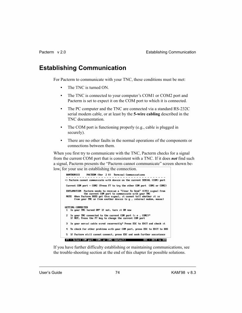
Establishing Communication
For Pacterm to communicate with your TNC, these conditions must be met:
• The TNC is turned ON.
• The TNC is connected to your computer’s COM1 or COM2 port and
Pacterm is set to expect it on the COM port to which it is connected.
• The PC computer and the TNC are connected via a standard RS-232C
serial modem cable, or at least by the 5-wire cabling described in the
TNC documentation.
• The COM port is functioning properly (e.g., cable is plugged in
securely).
• There are no other faults in the normal operations of the components or
connections between them.
When you first try to communicate with the TNC, Pacterm checks for a signal
from the current COM port that is consistent with a TNC. If it does not find such
a signal, Pacterm presents the “Pacterm cannot communicate” screen shown be-
low, for your use in establishing the connection.
If you have further difficulty establishing or maintaining communications, see
the trouble-shooting section at the end of this chapter for possible solutions.
Pacterm v 2.0 Establishing Communication
User’s Guide 74 KAM’98 v 8.3

Starting Pacterm
To start Pacterm, once you have connected your TNC to your computer:
1. Use DOS to go to the drive and directory where you have installed Pacterm.
For example, if you copied Pacterm to “C:\COMM” by using the Install pro-
gram, type “C:\COMM”, then press the ENTER key and you will see the
prompt “C:\COMM”.
+ Hint: If you are using Microsoft Windows 3.1 or above, you can use the Pro-
gram Manager, File Manager, or click on the DOS icon in the Main Window to
run Pacterm as a DOS program from within Windows. But do not run any other
program at the same time as Pacterm, or you may lose data.
2. Type PACTERM and press the ENTER key.
+ Hint: The drive and directory from which you call Pacterm does not need to be
the same as that where the program is stored. From Pacterm’s point of view, the
current drive and directory (e.g., used for SAVING the Holding Buffer) is the
drive and directory from which you start Pacterm. For example, suppose the
program PACTERM.COM is in C:\COMM (i.e., drive C, directory COMM)
and you are on directory SAVEBUFF on a disk in drive A
(A:\SAVEBUFF). In this case, the DOS command C:\COMM\PACTERM will
start Pacterm and the current drive and directory will be A:\SAVEBUFF.
3. The first screen you will see is the MAIN Menu screen. Use the SETUP
functions as needed, then you are ready to go on to the Terminal Screen.
4. Press the BACKSPACE key on the MAIN Menu to go to the Terminal
Screen and begin using Pacterm for communicating with your TNC.
5. If Pacterm cannot establish communication, it will assist by presenting a
“Pacterm cannot communicate” screen (shown above), which describes steps
you can take to establish communication. You may just need to turn on your
TNC and/or press the F7 key to tell Pacterm to try communicating through
COM1, instead of the default serial port, COM2. As soon as Pacterm can
communicate, it gives you the MAIN Menu, so you can try again.
Starting Pacterm Pacterm v 2.0
KAM’98 v 8.3 75 User’s Guide

Coordinating Pacterm and Your TNC
Several TNC parameter values affect how Pacterm communicates with the TNC.
Coordinating BAUD Rates: The Autobaud Routine
The first time your TNC is used, it runs an AUTOBAUD routine to assure that
the TNC baud rate is the same as that of Pacterm (or whatever communication
software is in use at the time).
The TNC’s AUTOBAUD routine works as follows:
1. AUTOBAUD sends and resends the message “PRESS (*) TO SET BAUD
RATE” to Pacterm, at one baud rate after another. When the TNC’s baud rate
matches that of Pacterm, you can read this message in a window on your
screen; if the two rates do not match, the message appears garbled.
2. Any time while this message is being sent, whether it is readable or garbled
on your screen, enter the “*” character (SHIFT+8 key combination).
3. When the AUTOBAUD routine receives, the “*” character from the serial
port, it uses that character to determine Pacterm’s BAUD rate.
+ NOTE: Do NOT use the “*” key on the number pad.
4. AUTOBAUD then sets the TNC’s BAUD rate to match Pacterm’s BAUD
rate. The TNC’s BAUD rate will be set to 9600 (Pacterm’s default BAUD
rate) unless Pacterm’s BAUD rate was changed before running
AUTOBAUD.
Technical note: The TNC’s BAUD rate is stored in the TNC as the value of the
ABAUD parameter, so when you use the TNC later, it will start with that BAUD
rate. This is made possible by an internal lithium battery supplied with the
TNC. Later, you can change the TNC BAUD rate if you want, as long as you
change Pacterm’s BAUD rate to match the new TNC BAUD rate.
Pacterm v 2.0 Coordinating Pacterm and Your TNC
User’s Guide 76 KAM’98 v 8.3

5. Finally, AUTOBAUD: (1) sends a “sign-on” message and (2) asks for the
user’s CALLSIGN, which will also be stored in the TNC and used until
changed. At this point, the user is ready to give commands to the TNC.
+ Hint: Do not confuse the TNC’s baud rate for serial communication on the
computer port with the TNC’s 1200 baud rate for communicating using the ra-
dio port, which is connected by a custom-wired cabling to a transceiver.
Configuring the TNC for Use with Pacterm
There are several TNC settings in addition to ABAUD (baud rate) and MYCALL
(CALLSIGN) that you may wish to change, especially if parameter values in
your TNC have been changed from their default settings. Even if you do not want
to change anything now, knowing about these parameters and knowing how to
reconfigure your TNC, gives you more control in using it with Pacterm.
Required TNC Parameter Settings
To work with Pacterm, the following TNC parameter settings are needed:
• COMMAND = $03 (CTRL+C) (default = $03, so unless this has been
changed, you do not need to do anything).
+ Hint: Pacterm has a fixed code that it sends for COMMAND and it is
the same as the TNC default value (HEX $03, which is CTRL+C from
the user’s point of view). That is, Pacterm assumes the TNC COM-
MAND parameter is set to its default value; if it is not, Pacterm com-
mands that send CTRL+C codes to the TNC will not work correctly.
• Each of the following TNC parameters needs to be set to its default
value, shown below, if it has been changed to a non-default value:
• CANLINE default = CTRL+X (HEX $18)
• CANPAC default = CTRL+Y (HEX $19)
• PASS default = CTRL+V (HEX $16)
Coordinating Pacterm and Your TNC Pacterm v 2.0
KAM’98 v 8.3 77 User’s Guide
Optional Parameter Settings
The following TNC parameters are generally used with their default settings
when running Pacterm, but you may wish to change them. If they have been set
to non-default values, you may wish to change them back.
• ECHO = ON (default)
• FLOW = ON (default)
Technical note: Usually, ECHO and FLOW go together, both ON or both
OFF. When using software that supports split screen displays, for example,
set both ECHO and FLOW to OFF.
• XFLOW = ON (default)
Technical note: XFLOW controls whether or not software flow control is
ON. If XFLOW is set to OFF, the following parameters should also be set to
0 (zero): XON, XOFF, START, and STOP.
• FILTER = OFF (default)
• 8BITCONV = ON (default)
+ Hint: Also, the MONITOR parameter may be ON or OFF (default = ON).
You may have Monitor ON while using Pacterm. But to prevent a build-up of
data in an internal buffer in the TNC, you should turn Monitor OFF when exiting
Pacterm and leave the TNC ON. This is because when the TNC’s receive buffer
is full, your station will give a BUSY signal to other stations that try to connect.
Pacterm v 2.0 Coordinating Pacterm and Your TNC
User’s Guide 78 KAM’98 v 8.3

Pacterm Screens
Pacterm has two screens for your use in working with your TNC:
• A MAIN Menu Screen, for setting up the communication, and
• A TERMINAL Screen, for sending commands and data to your TNC,
viewing data sent to Pacterm by your TNC, and using the functions
described on the MAIN Menu (except SETUP functions and ESC).
The MAIN Menu Screen
As shown below, the MAIN Menu screen shows all the functions available in
Pacterm and serves as a “Help” screen as well.
Each MAIN Menu function is described in detail later in this manual.
To go to the TERMINAL Screen from the MAIN Menu, press the BACKSPACE
key or use any MAIN Menu function other than SETUP functions, F10, or ESC.
Pacterm Screens Pacterm v 2.0
KAM’98 v 8.3 79 User’s Guide

The Terminal Screen
As shown below (in an example showing Pacterm connected to a KPC-3), the
Terminal Screen is in three parts, a viewing area, an input area, and a status line:
The Status Line
The Status Line gives the following information, from left to right on the line:
• Reminders of how to get to the MAIN Menu and how to EXIT to DOS.
• The current status of Flow Control Functions:
• Shows whether the user has set Pacterm to send data immediately to
the TNC (ONLIN) or to hold data to send it later (OFLIN).
• Shows whether the user has set Pacterm to request the TNC to send
data (START) or not to send data (STOP) .
• The current status of Output Control Functions:
• If the PRINT request is ON, PRINT is shown on the Status Line.
• If the Holding Buffer is OPEN, BUFF is shown on the Status Line.
• The current status of Hardware Control signals:
• While Pacterm permits the TNC to send it data, RTS is shown.
• While the TNC permits Pacterm to send it data, CTS is shown.
Pacterm v 2.0 Pacterm Screens
User’s Guide 80 KAM’98 v 8.3
Vie wing a re a(se e d a ta se nt
to Pa c te rm from
the TNC)
Inp ut a re a(se e m a te ria l
e nte re d , to se nd
to the TNC)
Sta tus Line

To go from the TERMINAL Screen to the MAIN Menu, press the F1 key.
Pacterm Commands: Overview
The following sections provide detailed specifications, helpful hints and technical
information on Pacterm commands. You may refer to this material now or just
start using the program and come back here later if you need more information.
On-Screen Help
The MAIN Menu screen and Terminal Screen have enough information so you
can use them as a guide to the commands available.
From MAIN Menu, BACKSPACE = Go to Terminal Screen
Pressing BACKSPACE to go to the Terminal Screen is the usual first step in a
session, once your COM port and BAUD rate are set up as you need.
MAIN Menu keys (except those used for SETUP or for EXIT to DOS) can also
be used to go to the Terminal Screen.
From Terminal Screen, F1 = Go to MAIN Menu
After you SETUP Pacterm and begin using the Terminal Screen, you will never
need to return to the MAIN Menu, except to change SETUP values
(COM port or BAUD rate) for the current session.
With the following exceptions, all commands that work on the MAIN Menu will
also work from the Terminal Screen:
• SETUP commands only work on the MAIN Menu.
• ESC and CTRL+C are interpreted as data in TERMINAL MODE,
so use them as data, not as ways to EXIT to DOS.
+ Hint: To EXIT Pacterm from the Terminal Screen, use F10, or go to the MAIN
Menu and use ESC or CTRL+C from there.
Pacterm Commands: Overview Pacterm v 2.0
KAM’98 v 8.3 81 User’s Guide
Commands: Setup, Using the MAIN Menu
Pacterm needs to know a few things in order to communicate with your TNC:
1. What mode of communication will you be using: packet or HF- Non-Packet.
If you are using a TNC (e.g. KPC-3 Plus), then you’ll be using packet.
Pacterm accommodates non-packet modes too for multi-mode Kantronics
TNCs (e.g. KAM Plus, KAM’98).
2. What COM port is going to be connected to the TNC? The default “current
COM PORT” is COM2, but you can switch to COM1.
3. What BAUD rate should Pacterm use to send data to the TNC? The default is
9600 BAUD, but you can select any of the following BAUD rates: 300, 600,
1200, 2400, 4800, and 9600.
+ Hint: Pacterm begins each session with the default settings for COM port
(COM2) and BAUD rate (9600), so if you are using non-default setting(s), you
will need to use the relevant SETUP function(s) to start each session.
F3 = Select TNC Use (Default = Packet)
Pressing F3 switches back and forth between two uses of your TNC: with Packet
communication (default) or with HF Non-Packet communication. The current
setting for this is shown on the MAIN Menu screen.
TNC users should always have Packet selected. Kantronics’ KAMs can operate
using either Packet or HF Non-Packet communication. Several functions work
differently in HF Non-Packet, so you should not select HF Non-Packet communi-
cation unless that is what you want to do.
+ Hint: If you accidentally press the F3 key and switch uses of your TNC, you will
know right away because: (1) the display of the current TNC use will change
from Packet to HF Non-Packet, and (2) a box will appear in the lower right of the
screen, showing additional functions that are for use with HF Non-Packet
communication instead of Packet communication. To switch back from
HF Non-Packet to Packet communication, simply press F3 again.
Pacterm v 2.0 Commands: Setup, Using the MAIN Menu
User’s Guide 82 KAM’98 v 8.3

F7 = Select SERIAL PORT (Default = COM2)
The TNC can operate with any COM port on your computer, but Pacterm can
only be used with COM1 or COM2.
Pressing F7 switches the current COM port from COM2 to COM1, or back.
Pacterm’s default COM PORT is COM2, so you do not need to do anything if
you have your TNC connected to COM2.
If you have your TNC on COM1 rather than COM2, you will need to press the
F7 key each time you start Pacterm. Just press F7 on the MAIN Menu before
pressing BACKSPACE to go to the Terminal Screen.
+ Hint: You could also use F7 to switch between two different TNC’s, one con-
nected to each COM port.
F8 = Select BAUD RATE (Default = 9600)
Pacterm can send and receive data through the current COM port at any of the
following BAUD rates: 300, 600, 1200, 2400, 4800, 9600 (default).
Technical note: At these levels, baud rate is essentially the same as
bits-per-second.
Press F8 to step through the available baud rates. Pacterm’s current BAUD rate is
shown on the MAIN Menu.
Since data flows back and forth between Pacterm and your TNC, both need to be
using the same BAUD rate for the communication to work. Pacterm always starts
a session at 9600 BAUD. If your TNC is also set for 9600 BAUD, you will not
have to change the setting.
+ Hint: If data sent from the TNC is garbled in the Viewing area of Pacterm’s Ter-
minal Screen, this may be due to a mismatch between the Pacterm and the TNC
BAUD rate. One way to coordinate them is to use F8 to step through various
BAUD rates for Pacterm, until incoming data is readable. Of course, this may
mean settling for a common BAUD rate that is less than optimal. Another way to
fix the mismatch is to change the TNC’s ABAUD parameter to match Pacterm’s
current BAUD rate. See the TNC documentation on the ABAUD command for
details on how to do this.
Commands: Setup, Using the MAIN Menu Pacterm v 2.0
KAM’98 v 8.3 83 User’s Guide

Commands: Controlling the Flow of Data
Data are ordinarily sent immediately from Pacterm to the TNC, and from the
TNC to Pacterm, but you may halt the flow of data in either direction.
Technical note: To avoid losing data, Pacterm and the TNC each need to know
when they have “permission” to send data to the other. Pacterm and the TNC
achieve this coordination using hardware flow control signals on the RS-232C ca-
ble connecting the two devices: (1) the TNC changes the status of the CTS (clear to
send) signal on one wire in the cable to tell Pacterm whether it is OK or NOT OK to
send it data, and (2) Pacterm changes the status of the RTS (request to send) signal
on another wire in the cable to tell the TNC whether it is OK or NOT OK for the
TNC to send data to Pacterm. The current status of each hardware control signal is
shown on the right end of the status line (RTS is shown if RTS is ON; CTS is shown if
CTS is ON)
F5 = Pacterm to TNC: Offline or Online (Default)
Pressing F5 (from either the MAIN Menu or the Terminal Screen) switches be-
tween two options controlling when data are sent from Pacterm to the TNC:
1. ONLINE = immediate transmission of data to the TNC as you enter it from
the computer (default setting), and
2. OFFLINE = type ahead, which orders Pacterm to stop the immediate trans-
mission of data and save the data in a transmission buffer, also called a
type-ahead buffer, for transmission to the TNC when you switch back ON-
LINE.
Caution: Don’t go OFFLINE for long. Pacterm’s type-ahead buffer (transmis-
sion buffer) holds a maximum of 1,024 characters, after which old data will be
discarded to make room for new data (i.e., it is a “first-in first-out” buffer)
The status line on the Terminal Screen shows either ONLIN or OFLIN.
Pacterm v 2.0 Commands: Controlling the Flow of Data
User’s Guide 84 KAM’98 v 8.3

F6 = TNC to Pacterm: STOP or START (Default)
Pressing F6 (from either the MAIN Menu or the Terminal Screen) switches
between the following two options for data-flow from the TNC to Pacterm:
1. START = Request that data be sent from the TNC to Pacterm, beginning with
any data previously held in the TNC while data-flow from the TNC was
STOPPED.
2. STOP = Do not send data from the TNC to Pacterm; instead, hold it for send-
ing when data-flow from the TNC is enabled (START).
+ Hint: While the TNC is STOPPED from sending to Pacterm, data are saved in
the TNC in a temporary buffer, until the buffer is full. When this buffer is full,
your station will give a BUSY signal to other stations that try to connect.
The status of this command (START or STOP) is shown on the Status Line.
Technical note: START is a request for the TNC to send any new data to Pacterm.
Before new data will actually be sent to Pacterm, however, Pacterm must be able to
receive material (RTS is ON), as indicated by RTS shown on the Status Line. While
it is SAVING the contents of the Holding Buffer, for example, Pacterm turns RTS
OFF automatically, so new material from the TNC will not be lost during the saving
operation.
Commands: Output Control
Pacterm provides the following output controls:
• PRINT data as it is shown in the Viewing area of the Terminal Screen.
• SAVE data shown in the Viewing area of the Terminal Screen in a
Holding Buffer, whose contents can later be saved as a file.
• SEND a copy of a file to the TNC.
Commands: Output Control Pacterm v 2.0
KAM’98 v 8.3 85 User’s Guide

ALT+P = Printer: ON or OFF (Default)
This controls whether or not new material appearing in the Viewing section (top)
of the TERMINAL Screen will also be sent to your printer. Pressing the ALT+P
key combination from either the MAIN Menu or the Terminal Screen switches
PRINT from OFF to ON and from ON to OFF.
+ Hint: If you request printing and your printer is not turned on, is out of paper, or
is otherwise unavailable, Pacterm will let you know, so you can correct the prob-
lem and try again.
The word PRINT appears on the Status Line when the Print request is ON.
Pacterm assumes that your printer is (1) a generic dot matrix text printer, such as
an Epson MX, which operates on a line by line basis, responding to carriage re-
turns and line feeds, and (2) connected to your computer’s LPT1 port.
+ Hint: If your printer (e.g., some laser printers) cannot be configured to operate as
Pacterm requires, you may get print-outs by copying material to the Holding
Buffer, saving it as a file, then using any text editor or word processor to bring in
the (ASCII) file and print it.
Caution: Using ALT+P to turn PRINT OFF while printing may cause errors.
ALT+B = Holding Buffer: OPEN or CLOSE (Default)
This command OPENS and CLOSES Pacterm’s Holding Buffer, which can be
used to store and later save up to 45K of data sent from the TNC to Pacterm.
To OPEN the Holding Buffer, press the ALT+B key combination; to CLOSE it,
press the ALT+B key combination again. You may OPEN and CLOSE the buffer
as you wish, until it is full, to “grab” the parts of a session that you may want to
save to a file.
When the Holding Buffer is OPEN, data sent to Pacterm and appearing in the
Viewing area of the Terminal Screen will be added to whatever has already been
stored in the Holding Buffer. While the Holding Buffer is CLOSED no new data
can be added, but what is already stored there stays until you clear it, save it, or
exit Pacterm.
Pacterm v 2.0 Commands: Output Control
User’s Guide 86 KAM’98 v 8.3
+ Hint: When the Holding Buffer is OPEN but full, Pacterm will automatically
CLOSE it if there is an attempt to add any more data to it. This means that once it
is full, the Holding Buffer will not be able to accept any more data during the
current session until it is cleared or saved.
When the Holding Buffer is OPEN, the term BUFF appears on the Status Line of
the Terminal Screen.
ALT+C = Holding Buffer: CLEAR
Press the ALT+C key combination to CLEAR (delete) the current contents of the
Holding Buffer, whether it is currently open or closed.
Caution: This command takes effect immediately and it cannot be undone, so be
sure you want to CLEAR the Holding Buffer before you use this command.
F2 = Holding Buffer: SAVE and CLEAR
Press F2 to SAVE the current contents of the Holding Buffer to a file in the cur-
rent directory (or to the current directory of a designated drive, if you include a
drive name with the file) and then automatically CLEAR the Holding Buffer.
You will be asked to supply a name for the file, using the standard DOS file name
conventions, and press ENTER to initiate the SAVE operation.
You may also include a drive name, along with the file name, to save the file in
the current directory on a drive other than the current drive. The drive name is in-
cluded in the 14 characters available for the name (e.g., add “C:” to the beginning
of the file name to store the file in the current directory of drive C).
Commands: Output Control Pacterm v 2.0
KAM’98 v 8.3 87 User’s Guide

+ Hint: Give the file name fairly promptly (e.g., within a minute or less). This is
because as soon as you ask to SAVE the Holding Buffer contents, Pacterm will
automatically STOP the flow of data from the TNC (turn RTS OFF), so you can
enter a file name and SAVE the current contents of the Holding Buffer without
losing any data from the TNC. During this time, new data are stored in the TNC’s
temporary buffer, and when this buffer is full the TNC will not accept further in-
coming data. After the Holding Buffer has been saved, Pacterm will automati-
cally enable the flow of data from the TNC (RTS ON, unless Pacterm’s F6
control is set to STOP) and the TNC will send the contents of its temporary
buffer to Pacterm before sending new data.
If you enter an invalid file name, or if the Holding Buffer is empty, Pacterm will
notify you so you can return to the Terminal Screen.
Caution: If the drive where you try to SAVE the Holding Buffer contents does
not have enough space available to save the file, or if the drive door is open, you
will get the standard DOS message: “Not ready reading drive (n): Abort, Retry,
Fail?” If you can fix the problem (e.g., shut the door or insert a disk with enough
space, if you are saving to a floppy drive), do so, type R (for Retry) and press the
Enter key. To withdraw the SAVE request, type F (for Fail) and press the Enter
key. If you type A (for Abort) and press the Enter key, you will EXIT to DOS,
which means the Holding Buffer will be cleared without being saved.
Caution: If you enter a valid DOS file name, Pacterm will use it without check-
ing to see if you already have a file by that name in the current directory (or in the
current directory of a designated drive, if you include a drive name with the file).
Be careful not to use a file name already in use, unless you want to write the new
file in place of the old one.
Two ways to Save Holding Buffer Data
There are two ways to save the current data:
• Binary file: To save the data without making any changes to it (e.g., to
save a downloaded binary file), give the extension “BIN”, for “binary,”
as part of the file name.
Pacterm v 2.0 Commands: Output Control
User’s Guide 88 KAM’98 v 8.3

• Text file: If the file does not have the BIN extension, Pacterm:
(1) removes all control characters except those for carriage returns and
tabs, (2) adds line-feeds to carriage returns, so text will flow from line to
line rather than overwriting the same line again and again with each
carriage return, and (3) adds additional carriage returns and line feed
characters where needed to force the material to “wrap” appropriately
when it is displayed on a screen (after 75 or 80 characters, depending on
whether or not there is a space character at the beginning of a given line).
Note that since the backspace control character, used to backup and
overwrite typing errors before sending data, will be filtered out, both
original and corrected characters will remain in the data that are saved.
Technical note: In both cases, Pacterm will add an “End of File” (EOF) code
(CTRL+Z) at the end of the data from the Holding Buffer.
ALT+F = Send a File to Your TNC
You can use Pacterm to send a file from your computer to your TNC, which is
then responsible for sending it on to your transceiver for transmission:
1. Use Pacterm to put your TNC in either Conversation Mode or Transparent
Mode connection with another station. In Conversation Mode, control char-
acters are interpreted as commands rather than as data. If you are sending a
text file for transmission by your TNC, you may wish to have the TNC in
Conversation Mode. If you want all control characters passed through as
data, use Transparent Mode. Do not have your TNC in Command Mode,
since it would then interpret data being sent to it by Pacterm as commands.
2. After setting up your TNC to handle the file it is going to receive from
Pacterm, press the ALT+F key combination to start the SEND file operation.
3. Pacterm will put a small square marker in the data-input area of the Terminal
Screen and wait for you to enter a DOS file name. Type the file name. Do not
include any blanks before or after the file name.
+ Hint: If the file is in the current directory on a drive other than the current drive,
include the drive name (e.g., C:) before the file name.
Commands: Output Control Pacterm v 2.0
KAM’98 v 8.3 89 User’s Guide

4. Press the ALT+F key combination again to ENTER the name. Pacterm will
respond by (1) putting another small square marker on the screen right after
the file name, (2) locating the file, and (3) sending a copy of it to the TNC.
Caution: If you give a file name that Pacterm cannot find, that is illegal, or
that is bounded by any blanks, Pacterm will not respond to the second ALT+F
command, so nothing will happen. Try again, starting with Step 2.
5. If your TNC is in Conversation Mode (but not if it is in Transparent Mode)
and it is set to ECHO, data will be echoed to the Terminal Screen.
Caution: Sending continues until Pacterm finds an end-of-file code. If the
file does not have an EOF code (CTRL+Z), some or all of the file will be sent
and resent until you EXIT to DOS to end the current session. To send such a
file successfully, add an EOF code (e.g., by using an appropriate word pro-
cessor).
Commands: Exiting
The following exit commands are available in Pacterm:
F9 = Switch Your TNC to Command Mode
From either the MAIN Menu Screen or the Terminal Screen, press the F9 key to
switch your TNC from Conversation Mode or Transparent Mode communication
to Command Mode (for the NEWUSER or TERMINAL Interface Mode, which-
ever your TNC is in at the time). Once in Command Mode, the TNC will inter-
pret data from Pacterm as being commands to carry out, not as data to transmit.
Technical note: Pacterm forces this switch by sending the TNC a specially timed
sequence of three CTRL+Cs (see TNC documentation for details).
When you use F9 to exit from Conversation or Transparent Mode to the Com-
mand Mode, the “cmd:” prompt will be appear in the viewing area of the Termi-
nal Screen. If you are already in Command Mode, using F9 has no effect.
Pacterm v 2.0 Commands: Exiting
User’s Guide 90 KAM’98 v 8.3

F10 = Disconnect and EXIT to DOS
From either the MAIN Menu Screen or the Terminal Screen, press F10 to
disconnect from a current connection that may have been established by the
TNC, EXIT Pacterm and go to DOS.
Pressing F10 sends the command sequence “CTRL+C, CTRL+C, CTRL+C, D”
to the TNC before exiting to DOS. The sequence of three CTRL+Cs in quick
succession changes the TNC to Command Mode if it was not already in Com-
mand Mode, and the D is a short form of the DISCONNECT command.
Caution: If there is no connection at the time, the TNC will report this fact, but
you will not see this report at the time, since you will EXIT Pacterm immediately.
You may see this message (“Can’t disconnect...”) when you start Pacterm again,
since it will have been stored in the TNC’s temporary buffer, waiting to be sent at
the beginning of a new Pacterm session.
+ Hint: If your TNC is turned OFF when you press F10, your computer may freeze
up when these commands are sent by Pacterm. Try turning the TNC back ON and
using F10 again to EXIT. If there is no response, just reboot your computer and
start another Pacterm session.
ESC or CTRL+C (on Main Menu Only) = EXIT to DOS
From the MAIN Menu, you can EXIT directly to DOS by pressing the ESC key
or by pressing the CTRL+C key combination.
When you are on the Terminal Screen, you cannot EXIT to DOS by pressing
ESC or CTRL+C. This is because at this time these are legal characters that can
be sent to the TNC, so they will just be added to the data stream. In Transparent
mode, each of these control characters will display as a graphic character in the
data shown on the Terminal Screen.
+ Hint: From the Terminal Screen, you may press F10 to Disconnect and EXIT to
DOS or use F1 to go to the MAIN Menu, from where you can use ESC,
CTRL+C, or F10, to EXIT to DOS.
Commands: Exiting Pacterm v 2.0
KAM’98 v 8.3 91 User’s Guide

HF Non-Packet Functions (For KAMs Only)
This section is not relevant to TNC users. It is included as part of a full descrip-
tion of Pacterm and as brief documentation for users of Kantronics’ KAM TNCs
with the following HF non-packet modes:
• RTTY
• ASCII
• AMTOR
• PACTOR
• G-TOR
• CW
As noted above, pressing F3 switches Pacterm between use with Packet and use
with HF Non-Packet.
+ Hint: When Pacterm is set to work with HF non-packet modes of communica-
tion, you can send a CTRL+C code to the TNC either by using the appropriate
Pacterm function or by entering the CTRL+C key sequence from the keyboard.
Commands that Work Differently in HF Non-Packet Mode
When Pacterm is in HF non-packet mode, the following commands have an “X”
added to the string of characters they send to the TNC:
• F9 = Go to “Command Mode.”
+ Hint: To change from one HF Non-Packet mode to another, you need to
return to the TNC’s Command Mode, so your TNC will be able to accept
the command for the next HF non-packet mode. You can do this without
using F3 to switch to Packet mode, if you are just switching from one HF
non-packet mode to another. If you do want to switch to Packet use of
your TNC, press F9 to go to Command Mode, then F3 to switch to
Packet use of your TNC.
• F10 = Disconnect (Break Link) and Exit to DOS.
Pacterm v 2.0 HF Non-Packet Functions (For KAMs Only)
User’s Guide 92 KAM’98 v 8.3

Additional Commands for HF Non-Packet
The commands listed below are only available during HF Non-Packet use of the
TNC (and only then are they shown on the Main Menu screen, in a box in the
lower right of the screen).
ALT+T (transmit) = Exit Type-ahead
This command can be used with all the HF Non-Packet modes listed above.
ALT+T sends a CTRL+C T CTRL+M sequence to the TNC. This causes the
TNC to key the radio and transmit the data in the TNC’s buffer. And if the F5
command had been used to put Pacterm in the type-ahead mode (offline), the sta-
tus line will change to show Pacterm as online (ONLIN).
ALT+R (receive) = Return to Type-ahead
This command can be used with all the HF Non-Packet modes listed above.
ALT+R sends a CTRL+C R sequence to the TNC. This will immediately return
the TNC to the receive mode, even if there is still data in its transmit buffer. Data
in the TNC’s transmit buffer will be saved for transmission later.
+ Hint: See ALT+E if you want to transmit all data in the TNC and then switch to
receive mode.
ALT+E = Return to Receive
This command can be used with all the HF Non-Packet modes listed above.
ALT+R sends a CTRL+C E sequence to the TNC. This will allow the data in
the TNC transmit buffer to be sent and then return the TNC to receive mode.
+ Hint: Used ALT+R when you want to hold the data in the TNC transmit buffer
and return the TNC to receive mode.
HF Non-Packet Functions (For KAMs Only) Pacterm v 2.0
KAM’98 v 8.3 93 User’s Guide

ALT+H = Shift Tone Pair Frequencies
NOTE: This Pacterm 2.0 command does NOT operate with the KAM’98. To
change MARK and SPACE in the KAM’98, go to Packet Command Mode (as de-
scribed in the “Getting Started” chapter) and set MARK and SPACE parameter
values directly.
This command can be used with the following HF Non-Packet modes: RTTY,
ASCII, and AMTOR.
ALT+H sends a CTRL+C S sequence to the TNC. This command changes shifts
in RTTY, ASCII, and AMTOR modes.
ALT+I = Invert Received Signal (rtty/ascii)
This command can be used with the following HF Non-Packet modes: RTTY,
ASCII, and AMTOR.
ALT+I sends a CTRL+C I sequence to the TNC. This command inverts the
received signal in RTTY, ASCII and AMTOR modes.
ALT+S n = Speed Change
This command can be used with the following HF Non-Packet modes: RTTY,
ASCII, and CW.
ALT+S n sends a CTRL+C n sequence to the TNC, where n is a number from 0
to 9. This command lets you change the speed at which you will transmit in
RTTY, ASCII or CW modes.
In RTTY or ASCII mode, n selects the nth item on the TNC’s list of
9 pre-programmed speeds. Use the value of n = 0 to change to the current value
of RBAUD or ASCBAUD, which may or may not be set to the default value
(default values are: RBAUD = 45, ASCBAUD = 110).
In CW mode, ALT+S n sets the transmit speed to 5*n words-per-minute
(e.g., ALT+S 3 = 5*3 = 15 words-per-minute). In CW mode, use n = 0 to set the
transmit speed to 50 words-per-minute (0 is interpreted as = 10, yielding
5*10 = 50 words-per-minute).
Pacterm v 2.0 HF Non-Packet Functions (For KAMs Only)
User’s Guide 94 KAM’98 v 8.3

Trouble-Shooting Difficulties in Communicating
If you are having difficulty establishing and maintaining communication between
Pacterm and your TNC, here are some points to consider in addition to those cov-
ered on the “Pacterm Cannot Communicate” screen.
Problem: Go to Terminal Screen, but Nothing Happens
One possibility is that the current COM port does have a device on it, but it is not
a TNC. It might be a mouse or an internal phone modem, for example. To see if it
is a mouse, go to the TERMINAL Screen, start moving your mouse and see if se-
quences of characters appear as you move the mouse. If so, change the COM port
setting in Pacterm and try again.
Problem: Your Computer Freezes Up
When Pacterm gets the go-ahead signal for communicating, it will act on the
assumption that the signal is from your TNC. There is no way Pacterm can verify
that the signal is actually coming from your TNC and not from another
device on the current COM port (e.g., a mouse, or an internal phone modem).
So if the device on the current COM port is not a TNC, Pacterm will be running
under a misunderstanding and, in this case, your computer may “freeze-up,”
requiring you to turn it off, re-start it, and take steps to correct the problem before
running Pacterm again.
Problem: You Are Getting Bad or Intermittent Data
Many PC compatible computers are designed with a built-in potential conflict
that may cause a problem: Both COM2 and COM4 (and both COM1 and COM3)
may use the same interrupt (IRQ) mechanism to get the attention of the computer.
This means that if devices on both COM2 and COM4 (or both COM1 and
COM3) are sending signals to the computer at the same time, this can cause
problems for programs, such as Pacterm, that use either COM port. If you are
getting bad data, check to see if you have another device that might be getting
confused with your TNC (on COM4 if your TNC is on COM2; COM3 if your
TNC is on COM1) and make it inactive or remove it while using Pacterm with
your TNC.
Trouble-Shooting Difficulties in Communicating
KAM’98 v 8.3 95 User’s Guide

Problem: Your TNC Stops Behaving Normally
Pacterm is intended for use with a TNC in NEWUSER or TERMINAL Interface
Mode (or, less often, in BBS or GPS Interface Mode), but it may receive data
from the TNC in any Interface Mode. Non-response, garbled data, or partially
garbled data may indicate the TNC has been switched to HOST or KISS mode
and needs to be switched back to NEWUSER or TERMINAL. See the TNC doc-
umentation for instructions on how to determine what Interface Mode your TNC
is in currently and how to change it to the Interface Mode you want (NEWUSER
or TERMINAL).
Pacterm v 2.0 Trouble-Shooting Difficulties in
User’s Guide 96 KAM’98 v 8.3

Getting Started
This chapter gives you important information and examples to get you started
using your multi-mode digital radio station.
We assume you have installed your station and familiarized yourself with the use
of Pacterm 2.0 with your KAM’98, as covered in the chapters on “Installing your
KAM’98” and on the DOS-based terminal program, “Pacterm 2.0.”
Hint: If you are familiar with other communication software, you may use it in-
stead of Pacterm 2.0. In this case, you need to be aware that Kantronics’ docu-
mentation and support services assume the use of Pacterm 2.0, at least for getting
started. If you have not yet installed your station, including Pacterm 2.0 commu-
nication software, and learned how to use Pacterm 2.0, we suggest that you do so
before continuing with this chapter.
Material covered here includes diagrams, explanations, and mini-tutorials on:
• the front panel of the KAM’98,
• beginning a session,
• Packet operations
• giving commands and transmitting data,
• the 22 NEWUSER commands,
• using selected NEWUSER commands,
• using the Personal Bulletin Board System that is in your KAM’98,
• switching to the full command set and back
• monitoring some HF modes
• radio teletype signals (RTTY)
• Pactor signals
• how to transmit in RTTY and Pactor
• switching to 1200 baud Packet (and back)
• monitoring VHF transmissions from nearby packet radio stations
• connecting to another station and initiating a packet conversation.
KAM’98 v 8.3 97 User’s Guide
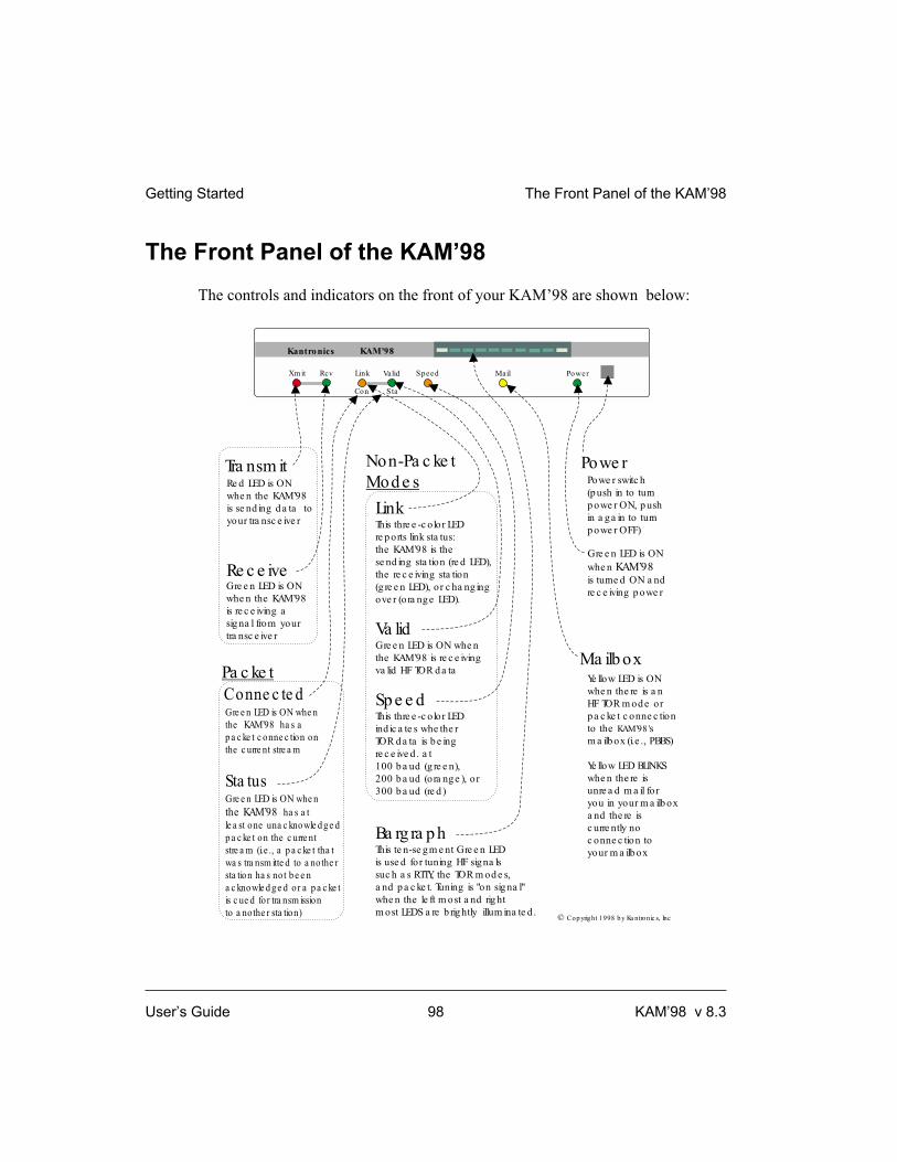
The Front Panel of the KAM’98
The controls and indicators on the front of your KAM’98 are shown below:
Getting Started The Front Panel of the KAM’98
User’s Guide 98 KAM’98 v 8.3
Powe r switc h
(p ush in to turn
p owe r ON, p ush
in a g a in to turn
p owe r OFF)
Gre e n LED is ON
whe n
is turne d ON a nd
re c e iving p owe r
KAM’98
Re d LED is ON
whe n the KAM’98
is se nd ing d a ta to
your tra nsc e ive r
Gre e n LED is ON
whe n the KAM’98
is re c e iving a
sig na l from your
tra nsc e ive r
Gre e n LED is ON whe n
the KAM’98 ha s a
p a c ke t c onne c tion on
the c urre nt stre a m
Gre e n LED is ON whe n
ha s a t
le a st one una c knowle d ge d
p a c ke t on the c urre nt
stre a m (i.e ., a p a c ke t tha t
wa s tra nsm itte d to a nothe r
sta tion ha s not b e e n
a c knowle d ge d or a p a c ke t
is c ue d for tra nsm ission
to a nothe r sta tion)
the KAM’98
Ye llow LED is ON
whe n the re is a n
HF TOR m od e or
p a c ke t c onne c tion
to the s
m a ilb ox (i.e ., PBBS)
Ye llow LED BLINKS
whe n the re is
unre a d m a il for
you in your m a ilb ox
a nd the re is
c urre ntly no
c onne c tion to
your m a ilb ox
KAM’98’
Tra nsm it
Conne c te d
Sta tus
Ma ilb ox
Powe r
Re c e ive
© Cop yright 1998 b y Ka ntronic s, Inc
Link
Va lid
Sp e e d
Ba rg ra p h
This thre e -c olor LED
re p orts link sta tus:
the KAM’98 is the
se nd ing sta tion (re d LED),
the re c e iving sta tion
(g re e n LED), or c ha ng ing
ove r (ora ng e LED).
Gre e n LED is ON whe n
the KAM’98 is re c e iving
va lid HF TOR d a ta
This thre e -c olor LED
ind ic a te s whe the r
TOR d a ta is b e ing
re c e ive d . a t
100 b a ud (g re e n),
200 b a ud (ora ng e ), or
300 b a ud (re d )
This te n-se g m e nt Gre e n LED
is use d for tuning HF sig na ls
suc h a s RTTY, the TOR m od e s,
a nd p a c ke t. Tuning is "on sig na l"
whe n the le ft m ost a nd rig ht
m ost LEDS a re b rig htly illum ina te d .
KAM’98
PowerXm it Rcv
Kantronics
Con Sta
Link Valid Speed Mail
Pa c ke t
Non-Pa c ke t
Mod e s

Beginning a Session
The steps involved in starting a session are covered in the “Pacterm 2.0” chapter,
so they do not need to be repeated here.
Recall that you need to turn on your KAM’98 and start Pacterm 2.0 (which runs in
your computer and provides you with a way to communicate with the KAM’98).
Once your initial setup is completed (including giving a CALLSIGN to your
KAM’98 and setting other parameters as needed), the first thing you will see
each time you start a new session is a sign-on message from the KAM’98
(sent to Pacterm 2.0 and displayed on your computer screen) such as the follow-
ing:
KANTRONICS ALL MODE COMMUNICATOR KAM ‘98 VERSION 8.3
(C) COPYRIGHT 1998 BY KANTRONICS INC. ALL RIGHTS RESERVED
DUPLICATION PROHIBITED WITHOUT PERMISSION OF KANTRONICS.
cmd:
The last line of this message (“cmd:”) is the KAM’98’s report that it is now in
“Command” mode, which means that it is now expecting information from
Pacterm 2.0 to be commands for it (the KAM’98) to interpret and carry out.
Before learning about the specific commands you can give the KAM’98, it is im-
portant to keep in mind the difference between giving the KAM’98 commands
and giving the KAM’98 data that is to be transmitted.
Packet Operations
Giving Commands and Transmitting Data
The KAM’98 will react to data received from Pacterm 2.0 (or any other source)
either as a command to follow or as information to transmit.
Command Mode (Packet)
When in the “COMMAND” mode of communication, the KAM’98 will
interpret data received from Pacterm 2.0 (or any other source) as being a com-
Packet Operations Getting Started
KAM’98 v 8.3 99 User’s Guide

mand to process, not as data to transmit. To instruct your KAM’98 to connect, to
disconnect, or to change any of the operating parameters in the KAM’98 you
must be in the COMMAND mode.
+ When placed in COMMAND mode (and ready to receive the next command) the
KAM’98 sends a “cmd:” prompt for display on the computer’s screen.
Converse (Conversation) Mode (Packet)
When in “CONVERS” (conversation) mode, the KAM’98 will interpret data re-
ceived from Pacterm 2.0 (or any other source) as data to transmit. In
“CONVERS” mode, the KAM’98 interprets most characters as information to be
transmitted, while interpreting certain pre-defined characters (which the user can
change) as control characters rather than as data to be sent. For example, a “back-
space” character causes a backspace and is not transmitted.
+ The KAM’98 will automatically switch to the CONVERS mode for you when
you connect to someone or when someone connects to you and will return to the
COMMAND mode when a disconnect occurs. When you are in COMMAND
mode, you may switch to CONVERS mode just by giving the command K
(or CONVERS). If you are in the CONVERS mode and want to force your
KAM’98 back to the COMMAND mode, you type a <Ctrl+C>.
TRANS (Transparent) Mode
A second way to transmit data is to instruct the KAM’98 to ignore the “control
characters” (e.g., “backspace”) and just transmit every character as data. This is
called the “TRANS” (transparent) mode of communication. For example, if data
received by the KAM’98 for transmission in TRANS mode includes “backspace”
characters (i.e., characters that would cause a backspace in CONVERS mode),
the KAM’98 will transmit the backspace characters as part of the data.
+ Before you can switch to TRANS mode, you need to set INTFACE to
TERMINAL instead of NEWUSER. (This is because, as described in the next
section, the TRANS command is not a NEWUSER command.) To get out of
TRANS mode and back to COMMAND mode, enter “<Ctrl+C> three times,with
a pause of less than one second between each entry.
Getting Started Packet Operations
User’s Guide 100 KAM’98 v 8.3

TNC Commands
You have a choice of whether to have your KAM’98 prepared to deal with a
small set of (22) NEWUSER commands (which is the default setting) or with the
full set of over 130 commands it is capable of carrying out.
+ Note: To switch to the full command set of the KAM’98, get in COMMAND
Mode (<Ctrl+C> or press F9 in Pacterm 2.0) and give the command INTFACE
TERMINAL. To switch back, give the command INTFACE NEWUSER.
NEWUSER Commands
The following diagram shows all the NEWUSER commands and summarizes
each command.
Packet Operations Getting Started
KAM’98 v 8.3 101 User’s Guide

Getting Started Packet Operations
User’s Guide 102 KAM’98 v 8.3
Kantronics NEWUSER Packet Commands
Get help and other information about your TNCHELP:
DISPLAY:
VERSION
List all available commands or a brief description of a specified command.Show current values for all parameters or for a specified group of parameters.
: Show the version number of the EPROM (firmware) installed in your TNC.
Define your TNC's use of characters sent to it from your computerECHO
BKONDEL
DELETE
: Display characters you type (default is ON, for use with full duplex communication programs).: Select the effect of entering a "delete" (i.e., erase the previous character or display a "\").
: Change which key your TNC will interpret as "delete" (default is backspace key).
NEWUSER commands are a subset of the full TERMINAL command set. NEWUSER commands are all youneed for basic, beginner operations of your digital radio station. These commands are explained in the
section of the manual.Command Reference
Select the current interface mode
INTFACE: Set the current interface mode to NEWUSER, TERMINAL, BBS, HOST, KISS, XKISS, or GPS.Default is NEWUSER, which makes available just the basic commands listed here.
Configure your TNC
RESET:
MYCALL
DAYTIME
TXDELAY
DWAIT
Restart the modem -- equivalentto turning your TNC OFF,then ON again ("soft reset").: Change your TNC's callsign.
: Set your TNC's software and hardware clocks.: Set the transmitter key-up delay (default is 300 ms).
: Time delay imposed to insure that digipeaters have priority access to the radio frequency.
Configure your personal mailbox (PBBS)
MYPBBS
PBBS
: Change the callsign of your PBBS.: Change the size of your PBBS (i.e., RAM used).
Session controlCONNECT
DISCONNE
UNPROTO
: Start a session (i.e., connect to a station) and automatically switch to CONVERS Mode.: End a session (i.e., disconnect from a station).
: Set a destination and digipeater path for unproto packet transmissions.
Display communication activityMONITOR
STATUS
MHEARD
: Display packets from other stations (default is ON).: Display current I/O stream and link status of other connected streams.
: Display a list of stations recently heard by your TNC.
CONVERS
K CONVERS.
: Switch from COMMAND communication mode to CONVERS (i.e., conversation)Mode. The default way to go to COMMAND Mode is to enter <Ctrl+C>.
: Same asback
Switch from giving your TNC commands to using it to send data

List of NEWUSER Commands
The following is an alphabetical listing of the 22 NEWUSER commands, with a
brief description of each command.
BKONDEL - When ON echoes a backspace-space-backspace sequence to the
screen each time you press the DELETE key to erase errors from your screen.
When OFF, echoes a \ for each press of the DELETE key.
CONNECT - Used to establish a packet connection with another station.
CONVERS - Places the TNC in CONVERS mode.
DISCONNE - Used to disconnect from a station you have been talking to.
DAYTIME - Used to read or set the clock in the TNC.
DELETE - Determines the character received from the computer which will
cause the previous character to be removed from the transmit buffer.
DISPLAY - Causes a screen display of all TNC parameters.
DWAIT - Time delay imposed to insure that digipeaters have priority access to
the radio frequency.
ECHO - When ON characters you type on the keyboard will be echoed back to
your terminal. When OFF characters you type will not be echoed.
HELP - Displays a complete list of all available commands on your screen.
INTFACE - Selects the NEWUSER command set or the complete (TERMINAL) com-
mand set. Also used to place the TNC in HOST, BBS, KISS, XKISS, or GPS mode.
K - Switches the TNC into the CONVERS mode (same as CONVERS).
MONITOR - When ON allows the TNC to display monitored packets on the
screen. When OFF, no packets will be displayed unless someone actually con-
nects to you.
MHEARD - Displays a short list of stations that have recently been heard by
your TNC.
MYCALL - Used to set the callsign of your TNC.
MYPBBS - Sets the callsign used for your personal mailbox in the TNC.
PBBS - Used to set the size (Kbytes) of the Personal BBS in your TNC.
Packet Operations Getting Started
KAM’98 v 8.3 103 User’s Guide

RESET - Causes the TNC to perform a soft reset.
STATUS - Displays the status of the current stream and all connected streams.
TXDELAY - Sets the time delay between Push-to-Talk and the beginning of data.
UNPROTO - Sets the destination field and digipeaters used for any unconnected
data packets transmitted.
VERSION - Displays the current version number of the EPROM (firmware) in
your TNC.
Using NEWUSER Packet Commands
A brief look at the use of selected NEWUSER commands will give you the fa-
miliarity you need to continue on your own using KAM’98 commands.
Check Your KAM’98’s Version Number and ID
To check your KAM’98’s version number and ID all you need to do is ask to see
the current setting of the command called VERSION:
Step 1. Go to COMMAND mode (if you are not already there).
Step 2. Type “VERSION” (or the short form, “V”) and press the
ENTER key to enter the command.
Step 3. The KAM’98 will send it’s version number and other ID
information for display on your monitor.
Get Help
To see a one-line explanation of any command that is currently available:
Step 1. Go to COMMAND mode (if you are not already there).
Step 2. Type “HELP,” (or “?”) followed by one or more spaces
and the name of the command for which you want help.
Getting Started Packet Operations
User’s Guide 104 KAM’98 v 8.3

Step 3. The KAM’98 will send a short “HELP” message about
the command, for display on your monitor.
View Current Values of Parameters
To see the current value of parameter(s) for any variable (other than the “immedi-
ate” commands, like CONVERS, that are simple actions, not settings):
Step 1. Go to COMMAND mode, as described above (if you are
not already there).
Step 2. Type the name of the command for which you want to
see current parameter value(s).
Step 3. The KAM’98 will send a message consisting of the
name of the command and the value(s) of it’s parameters
for display on your monitor. For example, if you type
INTFACE, you will see INTFACE NEWUSER if you
are currently in the NEWUSER mode.
+ As explained in the “Command Reference” chapter, the DISPLAY command
can be used to see current values of selected sub-sets of commands.
Change the Value of a Parameter
To change the current value of parameter(s) for any variable (other than the “im-
mediate” commands, like CONVERS, that are simple actions, not settings):
Step 1. Go to COMMAND mode, as described above (if you are
not already there).
Step 2. Type the name of the command for which you want to
change the current parameter value(s), type one or more
spaces, and enter the new value(s) you want for the pa-
rameter(s) for the command.
Packet Operations Getting Started
KAM’98 v 8.3 105 User’s Guide

Step 3. The KAM’98 will immediately change the value(s) to
the values(s) you have just entered.
+ If you enter a value that is not possible (e.g., INTFACE MOON), you will get
an error message (“EH?”).
To confirm that the current value(s) is what you want, enter the name of the com-
mand and press ENTER, The KAM’98 will send a message consisting of the
name of the command and the current value(s) of it’s parameters for display on
your monitor.
Connect to Your Mailbox (PBBS)
You are now ready to try your first connect.
A good first connect (which also shows you an important part of your KAM’98),
is to simply connect to your own personal mailbox, built in to the KAM’98:
+ This is an internal connect, so your radio does not need to be connected to do it.
Step 1. Go to COMMAND mode (if you are not already there),
where you will see the “cmd:” prompt.
Step 2. Type CONNECT call (where “call” is your MYPBBS)
and press the ENTER (return) key to enter the command.
By default, MYPBBS is the callsign you entered right
after the autobaud routine, with “-1" appended to it.
+ Note: To see the current mailbox callsign, type MYPBBS and press the ENTER
(return) key. The callsign shown in the one to use when connecting to your
mailbox (PBBS)
Step 3. Your KAM’98 will connect you to the mailbox. Your
screen should look something like this:
cmd:CONNECT NØKN-1
cmd:*** CONNECTED to NØKN-1
[KPC9612P-8.1-HM$]
5000 BYTES AVAILABLE
Getting Started Connect to Your Mailbox (PBBS)
User’s Guide 106 KAM’98 v 8.3

ENTER COMMAND: B,J,K,L,R,S, or
Help>
+ The commands now shown as available are just for the mailbox. The
KAM’98’s NEWUSER (and TERMINAL) commands become available again
when you exit the mailbox.
Step 4. Now you can give any of the mailbox commands shown
(B,J,K,L,R,S, or Help). Later you will want to read the
“PBBS (Personal Mailbox) section of the “Modes of
Operation” chapter for more details.
If you now type the HELP command and press return,
you’ll see the KAM’98 mailbox help file and then the
standard mailbox prompt:
ENTER COMMAND: B,J,K,L,R,S, or Help> .
Step 5. Now disconnect (just like you will disconnect from any
other user).
First, return to command mode by typing a <Ctrl+C> on
your keyboard. To do this, hold down the control key
(usually marked Ctrl) and type the letter C. Then let go
of the control key.
You should now see the “cmd:” prompt.
Next type the DISCONNE command and press return.
You will receive the message *** DISCONNECTED
and a new command prompt.
Congratulations. You have now completed your first connect.
Switching to the Full Command Set (and Back)
Now that you’ve learned how to enter commands and connect to the KAM’98 in-
ternal mailbox using the NEWUSER command set, it is time to turn on the full
command set of the KAM’98. You may do this by using the INTface command.
We’re going to set the KAM’98 in TERMINAL mode, a general mode that al-
Switching to the Full Command Set (and Back)
KAM’98 v 8.3 107 User’s Guide

lows you full access to all commands. To enter TERMINAL mode, at the cmd:
prompt type
INT TERMINAL <return>.
Then turn the KAM’98 off and back on, or at the cmd: prompt type RESET. You
are now in general TERMINAL mode. In fact, it may be that you’ll never change
this setting from now on. If you wish to go back to NEWUSER mode, just issue a
reset after entering the command INT NEWUSER. See INTface in the command
reference for more detail and additional choices.
Monitoring some HF Modes
Perhaps the quickest way to gain familiarity with using the KAM’98 to work the
HF digital modes is to monitor a few of these modes. Radio teletype (RTTY) and
Pactor are very popular on the 40 and 20 meter bands (7.0 and 14.0 Mhz), so try
using your HF Single Sideband transceiver (SSB radio), set in lower sideband
(LSB) mode, to copy these signal modes with the KAM’98.
+ RTTY transmissions are a steady sequence of 2125 and 2295 Hertz tones.
Pactor signals sound similar but pulsate at roughly a one second rate.
If you haven’t wired the output of your SSB radio speaker to the KAM’98 yet, do
so now. With it wired, turn it on and tune it to 14080 kilohertz, a portion of 20
meter digital band. Tune up and down the band a bit and you should readily find
both RTTY and Pactor signals.
Radio Teletype
To copy RTTY, i.e., display it on your computer screen, enter the following com-
mand at the “cmd:” prompt
cmd: RTTY <return>
The KAM’98 will respond with the message:
RTTY 45
You are ready to copy RTTY at 45 baud. Tune your dial up and then down until
you hear a RTTY signal. Once you’ve located one, adjust your dial until the left
Getting Started Monitoring some HF Modes
User’s Guide 108 KAM’98 v 8.3

edge and right edge LEDs of the KAM’98 bargraph light equally. At this point, if
the signal is indeed a RTTY 45 signal, you should see copy coming across your
computer screen.
To quit copying RTTY, enter the character sequence <Ctrl+C>X - that is, hold
the control character while typing the letter C, let up on both of them, and then
type the letter X. The command prompt (cmd:) should reappear on your screen.
You are now ready to view another mode.
Pactor Monitoring
To copy Pactor, enter the following command at the “cmd:” prompt, as follows:
cmd: PTLISTEN <return>
The KAM’98 is now set to listen to both parts of a Pactor ARQ exchange. Tune
up and down the dial until you hear a Pactor exchange in progress. Again, to tune
in the signal, adjust your radio dial until the left most and right most bargraph
LEDs light. At this point you should begin to see copy on your computer screen.
To quit copying Pactor, enter <Ctrl+C>X.
As before you went to Pactor, the command prompt should reappear on your
screen. You are back at the starting point, in Packet mode.
How to Transmit in RTTY and Pactor
While we won’t transmit right now, while in these modes all you have to do to
transmit is enter the <Ctrl+C>T sequence.
The KAM’98 is then placed in data transmit mode and you may type your mes-
sage. At any time, you may enter a control-C and E combination, and this action
will return you to receive mode just as soon as the data you have typed is all
transmitted.
Switching to 1200 baud Packet (and back)
Now that you have seen how to copy some HF signals, let’s enter the commands
necessary to switch the KAM’98 modem so that it will copy VHF packet frames
How to Transmit in RTTY and Pactor Getting Started
KAM’98 v 8.3 109 User’s Guide

(on 2-meters) at 1200 baud. What you are about to do is enter a series of com-
mands to switch the modem within the KAM’98 from 300 baud for HF packet
(which is where the modem is set when you turn your unit on the first time - at
which point you are at the command prompt, in Packet mode) to 1200 baud for
VHF packet use. In addition, you’ll adjust several packet parameters so that
packet operation on 1200 baud is optimal.
+ For more detail on these parameters and their commands, see the commands ref-
erence.
Now, enter the VHF parameter values for the commands listed in the following
table:
+ For reference, these are the recommended parameter values for HF and VHF
packet operation (each of which is set by a command of the same name):
Commands HF (default) VHF setting
hbaud 300 1200
mark 2125 1300
space 2295 2100
maxframe 1 4
paclen 64 128
persist 192 63
slottime 5 10
SWP 17,17,50 17,17,108
Now that you have converted your KAM’98 for VHF operation, connect a VHF
rig to the audio input of the KAM’98, and try copying some VHF 1200 baud
packets. Start by tuning the radio to 145.01 Mhz, the national packet frequency. If
you don’t find any activity there try 145.03, 145.05, or 144.390 (the national
APRS broadcast frequency.)
Since packet monitor is on (default setting) when you are in command mode,
there is no need to enter the MONITOR command to watch packets. You are al-
ready there. Simply watch the screen for packets as you hear their characteristic
squawk.
Assuming you see some, it is time to move on to other topics or switch the
KAM’98 modem parameters back for HF activity. To switch the modem back for
Getting Started Switching to 1200 baud Packet (and back)
User’s Guide 110 KAM’98 v 8.3

HF operation, just reenter the parameters you entered earlier for VHF operation,
but use the HF parameters in the table this time.
This concludes the “quick-start” section on non-packet operations of the
KAM’98. The following sections provide a “quick-start” on packet operations.
Monitor Communications From Nearby Stations
A good way to start using your packet radio station is to monitor communications
from nearby stations.
+ Amateur packet-radio activity is usually at VHF, on 2 meters, with 145.010 MHz
being the most common packet-radio frequency. The most common baud rate
is 1200.
To monitor communications from nearby stations (after you have tuned in to an
appropriate frequency):
Step 1. Set MONITOR to ON (if it is not already ON).
Step 2. Disconnect from any other station (or mailbox).
Step 3. As packets are received, you will see them displayed on
your screen. A typical received packet might look like
this:
NØKN>KBØNYK:
Hi Mike. How are you today?
The first line is the header line, and shows the callsigns
of the stations talking and the following line(s) are the
actual message that was sent. In the example, NØKN is
the transmitting station, and KBØNYK is the receiving
station. You may see the RCV LED light at times, indi-
cating a signal is being received, but nothing displays on
your screen. This is normal and may be the result of the
settings of the monitoring commands which are dis-
cussed in detail in the KAM’98 Command Reference.
Monitor Communications From Nearby Stations
KAM’98 v 8.3 111 User’s Guide

As you monitor, you will begin to learn about other packet stations in your area
and then you will probably want to try to connect to one of them.
Communicate Directly with a Nearby Station
Now you are ready to carry on a two-way conversation with another station. Here
we will see exactly what you need to do to connect to and converse with another
station.
Let’s say that you decide to connect to KBØNYK. The steps needed are as fol-
lows:
Step 1. First, be sure you have the KAM’98 in command mode.
To do this, type <Ctrl+C> and then press return. You
should see a command prompt (cmd:).
Step 2. Now you use the CONNECT command. To connect to
KBØNYK, you would simply type CONNECT
KBØNYK and press return, just as you did in the sample
connect to your mailbox.
+ In some cases you may need to use a relay station (called a digipeater) to con-
tact another station. This is similar to using a voice repeater when the station
you want to talk to is out of simplex range. To connect to a station using
digipeaters, you still use the CONNECT command, but you must also specify
the callsigns (or aliases) of the digipeaters that must be used. For instance, if
you need to use two digipeaters with callsigns of WØXI and NØGRG in order
to connect to KBØNYK, you would give the connect command as “CON-
NECT KBØNYK VIA WØXI,NØGRG”
Step 3. Once the connection has been made, you’ll receive a
message back on your screen from the KAM’98 that
says *** CONNECTED to KBØNYK (or, if you are us-
ing relay stations, *** CONNECTED to KBØNYK via
WØXI,NØGRG). At that point you are ready to start
talking to the other station since the KAM’98 has al-
ready automatically switched into the CONVERS mode.
Getting Started Communicate Directly with a Nearby Station
User’s Guide 112 KAM’98 v 8.3

Step 4. After you have completed your conversation, simply
press <Ctrl+C> to return your KAM’98 to the command
mode (“cmd:” will be displayed) and then you can in-
struct your KAM’98 to disconnect as you did above with
the mailbox, by entering D (or the full form,
DISCONNE) and return.
Other Topics
As you begin working with your KAM’98 packet radio station, other topics that
you may wish to explore (with the help of other sections of this manual) include:
• doing hard and soft resets,
• communicating via digipeaters (relays) with a distant station,
• using network nodes, and
• working with a GPS device.
This concludes a quick tour of basic uses of your KAM’98. With just these ba-
sics, you can do a lot, but you have a great deal more power if you want to ex-
plore the full possibilities.
For more information on all the topics we have covered here, and more, see the
following chapters in this manual.
Other Topics Getting Started
KAM’98 v 8.3 113 User’s Guide

Getting Started Other Topics
User’s Guide 114 KAM’98 v 8.3

Non-Packet Modes of Communication
Each non-packet mode of operation of the KAM’98 is described and illustrated in
this chapter.
+ For packet operations, see the following chapter, on “Packet Modes of Opera-
tion”.
You will benefit most from this section if you read it while you are at your station
with your KAM’98 connected to your computer and radio, so you can follow the
examples and experiment with your unit.
Start with your KAM’98 in the Command mode (as explained in more detail in
the “Getting Started” chapter).
When you turn the KAM’98 on, it will send its sign-on message (followed by the
“cmd:” command prompt):
KANTRONICS ALL MODE COMMUNICATOR KAM ‘98 VERSION 8.3
(C) COPYRIGHT 1998 BY KANTRONICS INC. ALL RIGHTS RESERVED
DUPLICATION PROHIBITED WITHOUT PERMISSION OF KANTRONICS.
Any time you want to operate the KAM’98 in a particular non-packet mode, you
must start from the command prompt (in Packet mode) and then switch by enter-
ing the command for (i.e., the name of) the non-packet mode you want to use.
+ The operational examples we use to explain these modes assume the use of a
standard terminal communications program, such as the DOS-based Pacterm 2.0
program provided with the KAM’98, or a telephone communications program,
such as Procomm Plus.
If you are using a specialized ham radio program, or a Host mode program such as
Host Master II (DOS) or Pacterm’98 (Windows 95/98/NT), the examples will not
apply. Host programs typically communicate with the KAM’98 for you, simplify-
ing your operation. Refer to your software manual if you are using these special-
ized programs.
KAM’98 v 8.3 115 User’s Guide

Tuning in the Signals
When operating most of the HF non-packet modes, use the bargraph on the front
of the KAM’98 as your tuning indicator. For RTTY, ASCII, AMTOR, Packet,
Pactor, and G-TOR operation, a properly tuned signal will light the two outside
LEDs on the bargraph. The left end of the bargraph is the MARK LED and the
right end is the SPACE LED. As signals are received, these two LEDs should
light with approximately the same brilliance.
+ Set your radio in lower sideband (LSB) mode to perate RTTY, ASCII, AMTOR,
PACTOR, or G-TOR.
When operating CW, the MARK LED will light when no signal is present, and
when a tone is received, the bargraph should move quickly and completely to the
SPACE LED. Slow movement toward the SPACE LED indicates that you are not
tuned properly on the CW signal.
AMTOR Operation
With your KAM’98, several modes of AMTOR operation are possible. Each
AMTOR station is identified by a SELCAL (Selective Call) which is derived
from your amateur callsign. The accepted practice in AMTOR is to use the first
letter of your callsign and the last three letters of your callsign as your AMTOR
SELCAL. The KAM’98 will automatically assign you SELCAL using this
method, but you may change it by using the MYSELCAL command. In addition,
the KAM’98 supports a 7-character SELCAL and generates a unique SELCAL
for this mode from your callsign. The KAM’98 will accept a link from another
station calling you with either the 4-character or 7-character SELCAL.
Mode A AMTOR is called ARQ and is a connected mode allowing you to com-
municate with just ONE other station at a time. The two stations send data back
and forth at a rapid interval (every 450 milliseconds); therefore, this mode re-
quires radios capable of switching from receive to transmit and back very rapidly.
Relay-switched radios typically cannot operate Mode A AMTOR.
Mode B AMTOR is called FEC. This mode broadcasts continually, allowing si-
multaneous reception by several stations. Since there is no back-and-forth trans-
mission between stations, the switching speed of the radios is not significant. A
Non-Packet Modes of Communication Tuning in the Signals
User’s Guide 116 KAM’98 v 8.3
subset of Mode B AMTOR is called SELFEC—Selective FEC. In this mode, sta-
tions limit reception to messages addressed to their “selcal”.
The third mode of AMTOR operation is listen-only, called LAMTOR. In this
mode, you can monitor two stations communicating with each other using Mode
A AMTOR; you can also monitor SELFEC transmissions that do not contain
your SELCAL.
+ For more information on AMTOR theory, you may want to read the American
Radio Relay League Operating Manual.
Mode A (ARQ) Operation
To operate Mode A AMTOR, you must first be sure you are in Command Mode
(cmd:). Type AMTOR and press return. This places your KAM’98 in the
AMTOR standby mode, and you will see the message “AMTOR STANDBY” on
your terminal. In this mode you can monitor other stations transmitting FEC
(calling CQ), transmit FEC to call CQ, and respond to a Mode A link request
from another station. NOTE: You will not be able to monitor or transmit FEC
from this mode if ARQBBS is ON. If AUTOSTRT is ON, you will only copy
SELFEC transmissions from other stations if they contain your SELCAL in the
transmission.
Calling CQ
To call CQ from this mode, type <Ctrl+C>T. The KAM’98 keys your transmit-
ter, the bargraph on the KAM’98 goes dark, and the transmit LED lights. Now,
type your CQ message on the keyboard. A typical CQ message would be like the
following:
CQ CQ CQ CQ DE NØGZZ NØGZZ (NGZZ)
CQ CQ CQ CQ DE NØGZZ NØGZZ (NGZZ)
CQ CQ CQ CQ DE NØGZZ NØGZZ (NGZZ)
SELCAL: NGZZ NGZZ
PSE K K K
When you’ve finished typing your CQ, type <Ctrl+C> E, instructing the
KAM’98 to return to the AMTOR Standby mode. After all of the data has been
transmitted, the KAM’98 will send the AMTOR STANDBY MESSAGE TO
AMTOR Operation Non-Packet Modes of Communication
KAM’98 v 8.3 117 User’s Guide

YOUR TERMINAL and enter Standby mode; the KAM’98 is now able to re-
spond to any station that attempts to link to you.
When a station links to you, your KAM’98 becomes the Information Receiving
Station (IRS), and the station that called you is the Information Sending Station
(ISS). When the other station keys in data, it will be transmitted to you and will
appear on your screen. At some point in the conversation, the other station will
“turn it over” to you so you can send data to him. Normally the other station will
make some kind of statement in the message to indicate that he is going to let you
send data. For instance, he might say, “SO HOW COPY?” The other station then
types a +?, which is transmitted to you. When the KAM’98 receives the +?, it is
displayed on your screen and you become the ISS. You now type on your key-
board, and this data is sent to the other station. When you want the other station
to again send data to you, type the +? on your keyboard. The +? is the “change-
over sequence” in AMTOR. Whenever the IRS receives this sequence, a change-
over occurs, allowing the other person to begin sending data.
At the end of the contact (QSO), one of the two stations must “break the link.”
This is equivalent to hanging up a phone at the end of a conversation. To break
the link with your KAM’98, type <Ctrl+C> D; the KAM’98 will then send the
AMTOR shutdown sequence to the other station, and both stations will stop
transmitting. Common practice among operators is that the ISS station sends a
short message indicating that he is going to break the link. Usually this consists
of something like “Link Down—SK.”
Answering a CQ
While you are in the AMTOR Standby mode, you may see another station calling
CQ and want to call that station. You must know the station’s SELCAL, and this
information is normally sent in the CQ message. In the example above, the sta-
tion’s SELCAL is NGZZ. If you want to call this station, you must first leave the
AMTOR Standby mode and get the command prompt (cmd:) from your
KAM’98. To do so, type <Ctrl+C> X.
From the command prompt, type AMTOR NGZZ and press return. Your
KAM’98 begins sending the link request to the other station and, after receiving
the proper acknowledgements, the message “ LINKED TO NGZZ” will appear
on your screen. You are now the ISS and you may begin typing your message to
be transmitted.
Non-Packet Modes of Communication AMTOR Operation
User’s Guide 118 KAM’98 v 8.3

From this point on, you will switch back and forth from sending station to receiv-
ing station with the changeovers as described above in “Calling CQ.” When the
conversation is finished, you or the station you are talking to must break the link.
If you want to break the link, type <Ctrl+C> D.
+ While you are linked to and receiving data from another station, you may want
to interrupt and make a comment of your own. To do this, you must first “seize”
the link, making your station the ISS. To do so, type <Ctrl+C> T. When you are
finished with your comment, use the normal +? changeover sequence to again be-
come the IRS.
Mode B (FEC) Operation
To operate Mode B AMTOR, you must first be in the Command mode (cmd:).
Type FEC and press return. This places the KAM’98 in the FEC mode without
sending any message to your terminal. In this mode you can receive any FEC
transmissions made by another station or transmit FEC from your station. Since
FEC can be copied by several stations at the same time, you would use this mode
to have a conversation with numerous stations at the same time (a round-table
discussion). NOTE: If AUTOSTRT is ON, you will only monitor SELFEC trans-
missions from other stations that contain your SELCAL in the transmission.
To transmit Mode B, type <Ctrl+C> T. This keys your radio, the bargraph on the
KAM’98 goes dark, and the red transmit LED lights. Type the message you want
to send. At the conclusion of your message, type <Ctrl+C>E. Your KAM’98 will
transmit your message in FEC mode and return to the receive mode when all of
the data has been transmitted.
Mode B (SELFEC) Operation
Receiving Mode B SELFEC
If you want to receive messages addressed just to you, set up the KAM’98 for
Mode B SELFEC receive. To do this, set the AUTOSTRT command ON in your
KAM’98, then enter the AMTOR Standby mode or the FEC mode as described
above. Your KAM’98 will now copy only Mode B SELFEC transmissions that
include your SELCAL in the transmission.
AMTOR Operation Non-Packet Modes of Communication
KAM’98 v 8.3 119 User’s Guide

+ During autobaud (setup), when you entered your callsign, your “selcal” was cal-
culated and stored. For details, see the MYSELCAL command.
Transmitting Mode B SELFEC
To transmit a Mode B SELFEC broadcast, type FEC followed by the selcal of the
stations you wish to send to and press return. The KAM’98 keys your radio, the
bargraph goes dark, and the red transmit LED lights. The KAM’98 sends the
Selcal you entered as the preamble to a transmission, followed by any message
you type on the keyboard. To return to receive, type <Ctrl+C> E. The KAM’98
unkeys the transmitter after all of the data has been transmitted, and will receive
ANY FEC transmission. Should you desire to receive just SELFEC transmis-
sions, you must have AUTOSTRT ON in the KAM’98.
When you are ready to transmit again, type <Ctrl+C> T. The KAM’98 will again
send the selcal you entered previously and then your next message. The selcal is
transmitted each time you start a new transmission while in the the SELFEC
mode. To cancel SELFEC mode, type <Ctrl+C>X to return to the Command
mode.
Listen AMTOR operation
To enter Listen AMTOR mode, the KAM’98 must first be in Command mode
(cmd:). Type LAMTOR and press return. This places the KAM’98 in a moni-
tor-only mode, enabling you to listen to Mode A, Mode B, or SELFEC AMTOR
transmissions. If you are monitoring a Mode A link between two other stations, it
is very possible that you will miss parts of the transmissions and print repeated
information. This occurs because you are copying two stations separated from
each other and from you. Also, in AMTOR, stations will repeat information that
is not received properly. You may “catch” these repeat copies! If you are receiv-
ing what appears to be random garbage characters while monitoring Mode A
AMTOR, you can force the KAM’98 to attempt to re-synchronize by typing
<Ctrl+C> R.
+ NOTE: You cannot transmit from the LAMTOR mode.
Non-Packet Modes of Communication AMTOR Operation
User’s Guide 120 KAM’98 v 8.3

Notes on AMTOR operation
You can set up your KAM’98 to automatically send a CW ID during Mode A op-
eration if desired. To do this, set the text you want to send (up to 15 characters)
with the CWIDTEXT command, set the CWPTT command ON and set ARQID
to the number of minutes between CW IDs. If you operate AFSK (SSB), you
must also set CWAUDIO ON. The CW ID speed is set by the CWSPEED com-
mand.
AMTOR directives
While operating your KAM’98 in the AMTOR modes, several directives are
available to perform various functions without returning to the Command mode
(cmd:). The directives and their purposes are as follows:
<Ctrl+C>A Abort link
<Ctrl+C>D Break link and remain in AMTOR Standby
<Ctrl+C>E Return to receive mode when transmit
buffer is empty
<Ctrl+C>I Invert received MARK/SPACE signals
and invert transmitted
MARK/SPACE if using AFSK (SSB)
<Ctrl+C>R Return to receive mode immediately in
FEC transmit. (If the transmit buffer
isn’t empty, the remaining data will
remain in the buffer.)
Re-sync if monitoring. If linked,
inserts +? (changeover) immediately. (If
the transmit buffer isn’t empty, the re-
maining data will remain in the buffer.)
<Ctrl+C>T Enter transmit mode—seize ISS status
<Ctrl+C>X Exit AMTOR mode and return to Command
mode (packet)
<Ctrl+C><Ctrl+T> Toggle TRACE mode ON/OFF
<Ctrl+W> Send Who Are You inquiry
AMTOR Operation Non-Packet Modes of Communication
KAM’98 v 8.3 121 User’s Guide

+ Some commercial HF-Internal gateway stations use SITOR mode (compatible
with AMTOR as implemented in the KAM’98) to process radio telex
ship-to-shore messages. See the Kantronics website (www.kantronics.com) for
articles on HF e-mail.
ASCII Operation
To operate ASCII mode with your KAM’98, you must first have the Command
prompt (cmd:). Type ASCII and press return. This places the KAM’98 in ASCII
mode. The ASCBAUD command controls the baud rate of the transmitted data.
If you want to operate ASCII at a different speed, enter the ASCII mode and
specify the speed on the command line (e.g., ASCII 200), then press return.
When you enter the ASCII mode, the KAM’98 sends the mode and speed indica-
tion to your terminal:
—ASCII 110—
The KAM’98 is now in the receive mode and will decode a properly tuned ASCII
signal and display the information on your terminal.
+ Note: If AUTOSTRT is ON, received ASCII will not be displayed until the
KAM’98 receives the characters contained in your MYAUTOST parameter.
To transmit ASCII, type <Ctrl+C> T. The KAM’98 then keys your transmitter,
the bargraph on the KAM’98 goes dark, and the transmit LED lights up. Type the
message you wish to send and when you are through, type <Ctrl+C>E. The
KAM’98 will transmit your message and, when the data has all been transmitted,
will return to the receive status.
You may change speeds while you are in the ASCII mode by using the
<Ctrl+C>n directives listed below. To leave the ASCII mode and return to Com-
mand mode, type <Ctrl+C> X.
Non-Packet Modes of Communication ASCII Operation
User’s Guide 122 KAM’98 v 8.3

ASCII Directives
While you are in ASCII mode, several directives are activated; they function as
indicated:
<Ctrl+C>E Return to receive mode when transmit
buffer is empty
<Ctrl+C>I Invert received MARK/SPACE signals and
invert transmitted MARK/SPACE
if using AFSK (SSB)
<Ctrl+C>R Return to receive mode immediately.
(If the transmit buffer isn’t empty, the
remaining data will stay in the buffer.)
<Ctrl+C>T Enter transmit mode
<Ctrl+C>X Exit ASCII mode and return to
Command mode (packet)
<Ctrl+C>n Change operating speed
n speed (baud)
1 45
2 50
3 57
4 75
5 100
6 110
7 150
8 200
9 300
0 ASCBAUD
CW Operation
At the command prompt, type CW and press return to place the KAM’98 in the
CW mode of operation. The KAM’98 will enter the CW mode, ready to receive
Morse code at the speed set in the CWSPEED command. The KAM’98 will auto-
matically adjust its receive speed to match the incoming signal within approxi-
mately +/-20 words per minute.
CW Operation Non-Packet Modes of Communication
KAM’98 v 8.3 123 User’s Guide

If you find that your KAM’98 prints a lot of Es and Ts while receiving, try set-
ting the CWBAND command to a smaller value. This narrows the input bandpass
filter on the KAM’98, and while it makes tuning a bit more difficult, it eliminates
much of the noise that results in poor copy. If a properly tuned CW signal on
your radio results in the tone being received at some frequency other than 750
Hz, you can change the KAM’98 center frequency using the CWTONE com-
mand.
Transmitting CW
To transmit CW with your KAM’98, you must wire the KEY OUT pin from the
radio port of KAM’98 to the key jack on your transceiver. The KAM’98 uses a
relay to provide a ground on this pin when sending CW, and therefore you must
turn OFF any internal electronic keyer in your radio. Be sure to have your radio
in the CW mode. You must also have your radio set for VOX operation so that it
will actually transmit any time the KAM’98 closes the KEYOUT relay. If you
prefer (or need) to have the KAM’98 directly key the radio into transmit, set the
CWPTT command ON and be sure you have the PTT line of the KAM’98 con-
nected to the PTT input to your radio. In this mode, you do not need the radio set
for VOX operation.
It is also possible to generate tone CW (audio tones applied to the microphone in-
put of your radio). This is most useful when sending code on an FM radio (i.e., 2
meters) for code practice or when connecting the KAM’98 to an amplifier and
speaker for local code practice. To use this mode, you must set the CWPTT com-
mand ON and the CWAUDIO command ON. The tone is frequency controlled by
the CWTONE command.
To begin transmitting CW, type <Ctrl+C>T to place the KAM’98 in the transmit
mode. Type your message on the keyboard, followed by <Ctrl+C>E. This causes
the KAM’98 to transmit your message and return to the receive mode when all of
the message has been transmitted.
In CW operation, several prosigns (character combinations) are used to indicate
end of message, break, wait, and many other common phrases. To transmit these
phrases with the KAM’98, type the keystroke shown to send the pre-defined
prosign.
Non-Packet Modes of Communication CW Operation
User’s Guide 124 KAM’98 v 8.3

Keystroke Prosign Meaning
+ AR End of Message
= BT Break or Pause
% AS Wait
& KA Attention
# SK End of Transmission
( KN Invitation to Transmit
* AA All After
! SN Attention
You may also generate any prosign by typing the PROSIGN character (default \)
and then the two characters to be combined.
In addition, the MORSE command allows you to define several special code
combinations. You can specify which key you type on the keyboard, the code
transmitted when you type that key, and the character(s) displayed on your termi-
nal when that code is received. (See the MORSE command for details.)
+ Note: If the CWPTT command is OFF, the KAM’98 front panel will not indicate
that you have entered the transmit mode, or that you have returned to receive. If
it is ON, the bargraph will go dark and the transmit LED will light up when you
are transmitting.
Receiving CW
During reception, you may find that the station transmitting is sending at a much
slower rate than you are set to transmit. You can lock your transmit speed to the
speed of the received station with the <Ctrl+C>L directive. This sets your trans-
mit speed approximately equal to the speed of the station. You may then send the
<Ctrl+C>U directive from the keyboard to unlock the KAM’98, allowing it to
again track the speed of the other station.
To exit the CW mode and return to the Command mode, type <Ctrl+C>X.
CW Directives
While your KAM’98 is in CW mode, several directives are possible. They func-
tion as follows:
<Ctrl+C>E Return to receive mode when
transmit buffer is empty
CW Operation Non-Packet Modes of Communication
KAM’98 v 8.3 125 User’s Guide

<Ctrl+C>L Lock transmit and receive speed to
current receive speed
<Ctrl+C>R Return to receive mode immediately.
(If the transmit buffer isn’t empty, the
remaining data will stay in the buffer.)
<Ctrl+C>T Enter transmit mode
<Ctrl+C>U Unlock receive speed to allow tracking of
incoming signal. Transmit speed stays at
current setting.
<Ctrl+C>X Exit CW mode and return to
Command mode (packet)
<Ctrl+C>n Change operating speed
n speed (wpm) n speed (wpm)
1 5 6 30
2 10 7 35
3 15 8 40
4 20 9 45
5 25 0 50
G-TOR Mode
G-TOR is a completely new hybrid - ARQ HF digital communications system for
commercial and amateur services. Golay error correction coding forms the basis
for G-TOR (short for Golay-TOR). G-TOR is an innovation of Kantronics, intro-
duced in 1994, first in the KAM Plus.
The benefits of G-TOR are exceptional, compared the previous multi-mode HF
digital modes: 1) substantially higher effective data rates (throughput); 2) appar-
ent reduction in the effects of interference and multi-path; and 3) a low cost for
error-correcting systems.
The key features of G-TOR are atypical: 1) extended Golay forward error correc-
tion coding; 2) full-frame interleaving; 3) on-demand Huffman and run-length
encoding; 4) link-quality-based baud rate: 300, 200, 100; 5) 2.4 second hy-
brid-ARQ cycle; 6) reduced data frame overhead; and 7) use of standard AFSK
tone pairs (mark and space).
Non-Packet Modes of Communication G-TOR Mode
User’s Guide 126 KAM’98 v 8.3

G-TOR operates as a synchronous ARQ mode, like AMTOR and Pactor. At 300,
200, or 100 baud, G-TOR’S ARQ cycle remains at 2.4 seconds. All data frames
are 1.92 seconds in duration and contain one control byte and two checksum
bytes (CRC). Data frames contain 69, 45, and 21 data bytes at 300, 200, and 100
baud respectively. Acknowledgements are 0.160 seconds in duration. The effec-
tive performance of two stations linked in G-TOR relies on the combined use of
forward error correction, data interleaving, and its ARQ cycle with CRC check-
ing. Operation in the G-TOR mode is described in the following sections.
G-TOR activity, at present, is found on all the HF bands near AMTOR and
RTTY. CW will typically be found at the bottom of the digital portion of each
band while AMTOR, RTTY, G-TOR, and Pactor are higher up the band in fre-
quency. For example, on 20 meters, activity can generally be found as listed be-
low. Note that G-TOR, Pactor, and AMTOR may tend to overlap.
CW 14.000 - 14.070 MHz
AMTOR, G-TOR, Pactor 14.070 - 14.085 MHz
RTTY 14.080 - 14.095 MHz
Packet 14.095 - 14.111 MHz
G-TOR Operation
The G-TOR protocol is a linked mode where two stations communicate with
each other. Although the G-TOR mode does not incorporate a broadcast mode,
G-TOR uses AMTOR fec for its broadcasts (from G-TOR Standby), such as call-
ing CQ. If you have the MONITOR command turned on when entering the
G-TOR mode, you will be able to monitor AMTOR fec transmissions.
The following example illustrates G-TOR operation with your KAM’98.
Turn the MONITOR command ON by typing MONITOR ON at the command
prompt (cmd:) and press return. This will enable you to copy CQ calls.
The G-TOR mode will use the mark and space tones set in your KAM’98. The
default values for these are MARK 2125 and SPACE 2295. You may wish to
change these to permit use of filtering or IF shift tuning in your radio.
Next, place your KAM’98 in G-TOR mode by typing GTOR at the command
prompt and pressing return. Your KAM’98 will respond with G-TOR STANDBY.
If you now tune your KAM’98 to a station transmitting AMTOR FEC, you’ll be
G-TOR Mode Non-Packet Modes of Communication
KAM’98 v 8.3 127 User’s Guide

able to copy that transmission. You’ll also be ready to receive a link request in
G-TOR mode from another station.
To call CQ, type <Ctrl+C>T. Your KAM’98 will enter the the AMTOR FEC
transmit mode, key your radio, and start transmitting. Type your CQ message on
the keyboard. It is very important that you include in your CQ the fact that you
are asking for a G-TOR contact. For instance, you might send:
CQ CQ CQ DE W0XI W0XI W0XI—-GTOR
CQ CQ CQ DE W0XI W0XI W0XI—-GTOR
CQ CQ CQ DE W0XI W0XI W0XI—-GTOR
PSE ARQ IN GTOR MODE ONLY
K K K
Be sure you include your callsign (as set by MYGTCALL) in the transmission.
After you have typed your entire CQ message, type <Ctrl+C> E. This will return
your KAM’98 to G-TOR Standby mode after all of the message has been trans-
mitted. Your KAM’98 is then ready to respond if someone calls you in G-TOR.
Tuning G-TOR
G-TOR signals are similar to AMTOR or Pactor signals in that MARK and
SPACE tones are used. Hence the bargraph indicator will be lit at both ends when
properly tuned. When you are linked to another G-TOR station, the CON LED
will be lit. The speed LED is used in G-TOR to indicate G-TOR speed (green for
100 baud, yellow for 200 baud, and red for 300 baud).
Monitoring G-TOR
In the G-TOR Standby mode, your KAM will monitor G-TOR CQ calls or other
G-TOR FEC broadcasts, which use the AMTOR FEC mode. In order to monitor
two stations that are linked to each other in G-TOR, use the GMON command.
Entering G-TOR Standby mode
To enter G-TOR Standby mode, simply type GTOR and press return from the
command prompt. Your KAM’98 will then respond to any attempt from another
station to link to you in G-TOR. You must have ARQBBS OFF if you wish to
talk to other stations from your keyboard. If ARQBBS is ON, a station who links
to you will be connected to your KAM’98 PBBS.
Non-Packet Modes of Communication G-TOR Mode
User’s Guide 128 KAM’98 v 8.3

Calling another station on G-TOR
To call another station using G-TOR, enter the GTOR command and callsign of
the station you wish to link to at the Command prompt. For instance:
cmd:GTOR NØQZZ
Your KAM’98 will begin transmitting a link establishment frame and, if the other
station is on the air and in G-TOR Standby mode, that station will respond to
your link request and you will see the message “linked to NØGZZ” on your
screen. You can then start typing your message to the other station. Since you
started the link, your station will be the “Information Sending Station” (ISS). Af-
ter you have entered your message, use the <Ctrl+C> E directive to allow the
other station to send data to you. This causes the KAM’98 to send the G-TOR
changeover sequence and you become the “Information Receiving Station”
(IRS). While the other station is sending data to you, you may force a changeover
(seize the link) by typing the <Ctrl+C> T directive. You then become the ISS
again.
Once you have concluded your conversation, you may break the link by typing
the <Ctrl+C> D directive. This will send the proper QRT frame to the other sta-
tion and return your KAM’98 to G-TOR Standby mode. Alternatively you may
use the <Ctrl+C> X directive, which will also break the link and return you to
the command prompt.
Speed changes
The signal rate is automatically selected in G-TOR, based on the quality of the
link between the two stations. A link will begin at 100 baud. If the receiving sta-
tion then detects a number of correctly received frames (set by GTUP), it will re-
quest a speed change to 300 baud. When operating at 300 baud or 200 baud, the
receiving station will request a lower speed when it receives a number of incor-
rect frames in a row (set by GTDOWN).
While you are linked to another station, the receiving station (IRS) controls the
speed of the link. If you are the IRS, you can force the other station to send at
100 baud by using the <Ctrl+C> 1 directive. The KAM’98 will then send the
speed change command to the other unit to change to 100 baud. Once the change
occurs, your KAM’98 will not direct the other station to speed up again until a
changeover has occurred or you set your KAM’98 back to auto-speed with the
G-TOR Mode Non-Packet Modes of Communication
KAM’98 v 8.3 129 User’s Guide

<Ctrl+C> 0 directive. If the change fails to occur for any reason, the KAM’98
will revert to the speed it was operating at prior to the <Ctrl+C> 1 directive.
If you are the IRS and wish to speed up, you can use the <Ctrl+C> 2 directive to
switch to 200 baud, or the <Ctrl+C> 3 directive to switch to 300 baud. The
KAM’98 will then send the proper speed change command to the other unit, and
if the command is successful, your KAM’98 will not request the other unit to
slow down even if the band conditions change, unless you set the KAM’98 back
to auto-speed with <Ctrl+C> 0 directive. We strongly recommend that you leave
your KAM’98 in the automatic baud rate selection mode.
G-TOR mailbox
Your KAM’98 allows access to its PBBS (mailbox) using GTOR mode. To en-
able a user to access the PBBS on GTOR, you must set the ARQBBS command
ON and place your KAM’98 in the GTOR Standby mode.
If you link to another station who is using a KAM’98, you will normally commu-
nicate with the operator at the other end. If that station has the ARQBBS com-
mand ON, you will automatically be connected to the PBBS and will receive the
mailbox prompt.
Formatting Data
When operating G-TOR, several of the KAM’98 commands, including the fol-
lowing, will apply in formatting your transmitted data.
CRADD adds a CR after every CR you send from the terminal.
LFADD adds a LF after every CR you send from the terminal.
CRSUP suppresses EVERY OTHER consecutive CR from the TNC.
LFSUP suppresses all LF characters from the TNC.
You should remember that any special characters defined in the KAM’98 (DISP
C) must be “passed” in order to transmit them from a standard terminal program.
Hints for G-TOR Operation
If you choose to use the FSK mode of your transceiver, you must connect the
FSK output from the KAM’98 to the FSK input of your radio. The actual tones
transmitted are controlled by your radio in this mode, and you must set your
Non-Packet Modes of Communication G-TOR Mode
User’s Guide 130 KAM’98 v 8.3

MARK and SPACE commands in the KAM’98 to match those tones. For in-
stance, the default MARK and SPACE in theYaesu FT-1000 are 2110 Hz for
MARK and 2310 Hz for SPACE.
Caution: When you are linked to another station and you want to break the link,
you should use the <Ctrl+C> A directive. This directive will attempt to send the
proper QRT sequence to the other station, but if the KAM’98 receives an invalid
response sequence (unrecognized CS code), it will immediately return to GTOR
Standby and discard any pending data. If you attempt to break the link with the
<Ctrl+C> X directive, the KAM’98 will attempt the QRT sequence, but will only
return to packet mode after receiving the proper acknowledgement (CS code) or
after GTERRS attempts to break the link. This could take a long time.
When you attempt to link to a nearby station, it is possible that the transceivers
(yours and the other station’s) may not switch fast enough to permit a link to oc-
cur. In this case, we suggest that both stations set the TXDTOR command to a
higher value (try 7, 8, or 9). This has been proven to allow links on very short
paths with very slow radios.
If you use an external power amplifier with your HF transceiver, you may set a
time delay to key your transmitter before the audio is sent to your radio by using
the PREKEY command. This command will allow your amplifier to turn on be-
fore full transmitter power is applied. You may also set the POSTKEY command
to stop the transmit audio before releasing the PTT line to your transceiver. (note
that PREKEY adds delay time before data begins.)
+ NOTE: Do not change TXDTOR, PREKEY, or POSTKEY values while you are
linked. This is only possible with Host mode programs, but changing these values
while linked will cause the link to fail.
Binary Files and G-TOR
The G-TOR mode provides complete data transparency, allowing binary file
transfers between G-TOR stations. The ability to send and receive binary files in
this mode will depend on the termal program you are using. Since G-TOR pro-
vides complete error detection and correction, binary files should sent in a raw
data mode—that is, no error correction protocol (such as X-modem) needs to be
used from your terminal program.
G-TOR Mode Non-Packet Modes of Communication
KAM’98 v 8.3 131 User’s Guide

Host mode programs simply include the raw binary data in the data stream; how-
ever, if you are using a standard telephone communications program, it is possi-
ble to allow the KAM’98 to send raw binary data. To do this, once you are linked
to another station in G-TOR, type the <Ctrl+C>B directive. This places the
KAM’98 in a data transparent mode, allowing ALL characters to be transmitted
from the computer.
CAUTION: When you have done this, no special characters are recognized by the
KAM’98, and no directives are available. Thus, typing <Ctrl+C> E, for instance,
will NOT cause a changover; it will simply transmit the <Ctrl+C> character and
the E to the other station. To exit this data transparency mode, you MUST send a
modem break signal. Most telephone communications programs support this fea-
ture. (Procomm Plus, for instance, sends a modem break when you press Alt-B.)
If your communications program does not support the modem break, you will not
be able to leave the data transparency mode.
The KAM’98 will automatically exit data transparency if the other station dis-
connects from you, or at any time your KAM’98 leaves the linked state (due to
errors or retries).
Summary of GTOR Directives
<Ctrl+C>A Abort a link or abort an attempt to link
after the first invalid response code.
<Ctrl+C>B Enter data transparency mode
(for binary file transfer)
<Ctrl+C>D Disconnect from the station you are
linked to. A changeover will be performed
if required, and the KAM’98 will return
to GTOR Standby mode.
<Ctrl+C>E (ARQ mode)Changeover from ISS to IRS when
all pending data has been transmitted.
(FEC mode—AMTOR FEC)Return to receive
when transmit buffer is empty
(used when calling CQ).
Non-Packet Modes of Communication G-TOR Mode
User’s Guide 132 KAM’98 v 8.3

<Ctrl+C>R Changeover from ISS to IRS immediately.
Return to receive immediately
(FED mode—AMTOR FEC)
<Ctrl+C>T Seize the link if IRS (ARQ mode)
Enter AMTOR FEC transmit mode
<Ctrl+C>X Disconnect the link (if linked) and
return to Packet
<Ctrl+C>0 Set automatic baud rate selection
<Ctrl+C>1 Force 100 baud operation (IRS only)
<Ctrl+C>2 Force 200 baud operation (IRS only)
<Ctrl+C>3 Force 300 baud operation (IRS only)
<Ctrl+C><Ctrl+T> Toggle TRACE mode ON/OFF
MODEM BREAK Exit data transparency mode
NAVTEX Operation
NAVTEX/AMTEX Theory
Navtex transmissions are, in reality, Mode B AMTOR (FEC). What makes
Navtex unique, however, is the actual message format. Navtex stations always
transmit on 518 kHz LSB, and are generally located on the coastlines. The same
format is now being used by the American Radio Relay League (ARRL) to trans-
mit bulletins on a daily basis. These bulletins are transmitted during scheduled
teleprinter bulletins.
At the beginning of a NAVTEX (or AMTEX) transmission, the sending station
will send a preamble, identifying the station that is transmitting, the type of mes-
sage, and the message sequence number. The preamble looks like this:
ZCZC AG25
The ZCZC is always present, and the receiving unit sees this as the indication
that the identifier is coming next. The components of the identifier, as defined in
the NAVTEX documentation, are:
B1 B2 B3 B4
B1 is used to identify the station that is transmitting, and consists of the letters A
through Z. B2 indicates the messages class (A through Z). Note that class A, B
NAVTEX Operation Non-Packet Modes of Communication
KAM’98 v 8.3 133 User’s Guide

and D messages must always be printed once. B3 and B4 are the sequence num-
ber for the message, and will have values from 00 throug 99. Messages with se-
quence number 00 are always printed. When the messages numbers reach 99,
they wrap to 01 as the next number.
The following stations may be on the air and transmitting NAVTEX:
Halifax, Nova Scotia Guam
Boston, MA Honolulu, HI
New Orleans, LA Kodiak, AK
Miami, FL Astoria, OR
San Juan, Puerto Rico Long Beach, CA
Chesapeake, VA San Francisco, CA
For NAVTEX messages, the currently assigned message classes are as follows:
A Navigational warnings
B Meteorological warnings (storm warnings)
C Ice reports
D Search and Rescue Information
E Meteorological forecasts
F Pilot messages
G Decca message
H LORAN-C message
I Omega message
J Differential Omega message
Z QRU - no message on hand
K-Y Reserved
+ NOTE: K has been proposed for “other electronic navigational aid sys-
tem message.”
Once a message has been received from a particular station with less than a spec-
ified amount of errors, it will not be printed again, as the receiving system keeps
track of the message numbers it has received. If it then sees the same message
class and number from the same transmitting station, it will not output the mes-
sage to the terminal.
For ARRL AMTEX bulletins, the defined B1 codes are as follows:
A ARRL issued bulletins
Non-Packet Modes of Communication NAVTEX Operation
User’s Guide 134 KAM’98 v 8.3

C CRRL issued bulletins (Canadian)
I IARU issued bulletins
J JARL issued bulletins
S AMSAT issued bulletins
X Miscellaneous
The currently assigned message classes are as follows:
A Emergency bulletins
B Priority bulletins
D Reserved
E DX bulletins
G General bulletins
K Keplarian bulletins
P Propagation forecasts
S Satellite bulletins
X Miscellaneous bulletins
NAVTEX/AMTEX Operation
To enter the NAVTEX/AMTEX mode, simply type NAVTEX from the command
prompt and press return. At this point, you will see nothing on the terminal until
a valid NAVTEX message is received.
To exit the NAVTEX mode and return to the command prompt,
type <Ctrl+C> X. (Do not hold the Control key when you type the X.)
Before entering the NAVTEX mode (while you still have the command prompt),
you may specify which stations you wish to receive using the NAVSTA com-
mand. For instance, if I wish to copy AMTEX bulletins issued by ARRL, but do
not want those from other stations, I type NAVSTA A at the command prompt. To
monitor all stations, simply type NAVSTA ALL.
You may also specify which message classes you wish to receive by using the
NAVMSG command. If you wanted the Satellite bulletins and DX bulletins, you
would type NAVMSG ES and press return. If you eliminate message classes A,
B, or D from the list of valid message classes, you will receive a WARNING
message from the KAM’98 since the NAVTEX specification requires that these
classes must be printed at least once.
NAVTEX Operation Non-Packet Modes of Communication
KAM’98 v 8.3 135 User’s Guide

The NAVERR command is used to specify the percent of errors allowed in a re-
ceived message before the KAM’98 considers the message as not being received
properly.
If you wish to clear the message sequence numbers, allowing all messages to be
received again, use the NAVCLR command. If the Navtex mode is used infre-
quently, it is advisable to clear the numbers, since the transmitting station may
have already wrapped sequence numbers back around to those you have stored.
Pactor Operation
Pactor operation is possble in two modes. The first mode, normally referred to as
ARQ mode, is a “connected” or linked mode where two stations are in conversa-
tion with each other. Complete error checking occurs in this mode and the receiv-
ing station will request retransmission of any data frames containing errors. The
KAM’98 uses memory ARQ in this mode to improve reception.
The second mode of operation transmits data in an unconnected (or unlinked)
state, allowing several stations to copy the transmission. This is referred to as the
FEC mode, and is the mode used for calling CQ or for other broadcast transmis-
sions. Receiving stations do not use memory ARQ to copy FEC transmissions;
therefore, a frame must be copied without any errors in order to be printed. You
might miss complete frames when receiving FEC broadcasts.
Monitoring Pactor FEC
To operate Pactor mode with your KAM’98, you must first go to the command
prompt. Type PACTOR and press return. This places your KAM’98 in Pactor
Standby mode, and the message “PACTOR STANDBY” is displayed on your ter-
minal. NOTE: Since the MONITOR command is ON by default, your KAM’98
will now monitor any Pactor FEC or ARQ transmissions.
Calling CQ or Transmitting FEC
To call CQ, place your KAM’98 in the Pactor Standby mode by following the di-
rections above. To begin transmitting, type <Ctrl+C>T. This keys your transmit-
ter, the bargraph on the KAM’98 will go dark, and the HF transmit LED will
light up. Type in your CQ message, then type <Ctrl+C>E. Your KAM’98 will re-
Non-Packet Modes of Communication Pactor Operation
User’s Guide 136 KAM’98 v 8.3

turn to the Standby mode after the data has been transmitted, and will respond
automatically if another station attempts to link to you. A typical Pactor CQ
might be:
CQ CQ CQ de NØGZZ NØGZZ NØGZZ
CQ CQ CQ de NØGZZ NØGZZ NØQZZ
CQ CQ CQ de NØGZZ NØGZZ NØGZZ
K K K
Connecting to another station
Suppose you see someone calling CQ and you want to call that station back.
First, return to the Command mode by typing <Ctrl+C>X. Your KAM’98 sends
the command prompt to your terminal. Next, type PACTOR xxxxxx (where
xxxxxx is the callsign of the station you want to call), then press return. You
KAM’98 now attempts to connect to the other station by keying your transmitter
and sending the link request. When the other station has properly acknowledged
the request, your KAM’98 sends the message “ LINKED TO XXXXXX” to your
terminal. Since you started the link, you are the Information Sending Station
(ISS) and may begin typing your message. When you have finished your part of
the conversation and want to receive from the other station, type <Ctrl+C>E.
This causes the KAM’98 to send a request for the other station to begin transmit-
ting data (a changeover). You then become the Information Receiving Station
(IRS) and the other station’s message will appear on your screen.
When you have completely finished your conversation, one of the two stations
must “break the link,” or disconnect. Your KAM’98 allows you to issue the dis-
connect command when you are either the IRS or the ISS. To disconnect, type
<Ctrl+C>D. If you are the IRS, the KAM’98 will first perform a changeover and
then perform the disconnect sequence. You may leave the Pactor Standby mode
by typing <Ctrl+C>X.
+ NOTE: If the station to which you are trying to connect to is a long distance
away, you may need to use the Pactor’s long-path option when you attempt to
connect. This will only be required if the station is more than about 5500 miles
away. To connect long-path on Pactor, precede the callsign of the station with an
exclamation point (!) when starting the connection (e.g., PACTOR !W0XI).
Pactor Operation Non-Packet Modes of Communication
KAM’98 v 8.3 137 User’s Guide

Monitor Only Mode
You may monitor PACTOR by using the PLISTEN command. To enter this
mode, you must first have the command prompt (cmd:). Type PTLISTEN, then
press return. You can now monitor FEC or ARQ Pactor signals. The KAM’98
will not respond to any attempt to link while in the monitor mode.
To exit this mode, type <Ctrl+C> X.
Pactor Directives
While operating your KAM’98 in the Pactor modes, several directives are avail-
able to perform various functions without returning to the Command mode
(cmd:). The directives and their purposes are as follows:
<Ctrl+C>A Abort a link or abort an attempt to link
after the first invalid response code.
<Ctrl+C>D Disconnect
<Ctrl+C>E Changeover from ISS to IRS (ARQ mode)
when transmit buffer is empty.
Return to receive when transmit buffer
is empty (FEC Mode).
<Ctrl+C>R Changeover from ISS to IRS (ARQ mode).
Changeover is immediate;
if data has not all been transmitted,
it stays in the transmit buffer.
<Ctrl+C>T Seize the link if IRS (ARQ mode)
Enter transmit mode (FEC mode)
<Ctrl+C>X Disconnect the link (if linked) and
return to Packet
<Ctrl+C>0 Set automatic buad rate
<Ctrl+C>1 Force 100 baud mode
<Ctrl+C>2 Force 200 baud mode
<Ctrl+C><Ctrl+T> Toggle TRACE mode ON/OFF
Non-Packet Modes of Communication
User’s Guide 138 KAM’98 v 8.3

RTTY Operation
To operate radio teletype (RTTY) with your KAM’98, first go to the command
prompt, then type RTTY, and the press return. This places the KAM’98 in the
RTTY mode. The baud rate of the transmitted data is controlled by the RBAUD
parameter. If you want to operate RTTY at a different speed, you may enter the
RTTY mode by giving the RTTY command and specifying the speed on the com-
mand line (e.g., RTTY 75), then press return. When you enter the RTTY mode,
the KAM’98 sends the mode and speed indication to your terminal:
—RTTY 45—
The KAM’98 is now in the receive mode and will decode a properly tuned RTTY
signal, and will display the information on your terminal.
+ Note: IF AUTOSTRT is ON, received RTTY will not be displayed until the
KAM’98 receives the characters contained in your MYAUTOST parameter.
To transmit RTTY, type <Ctrl+C>T. This causes the KAM’98 to key your trans-
mitter, the bargraph in the KAM’98 goes dark, and the transmit LED light. Type
the message you wish to send and when you are through, type <Ctrl+C>E. The
KAM’98 will transmit your message and, when the data has been transmitted, re-
turn to the receive mode.
Use the <Ctrl+C>n directives listed below to change speeds while operating the
RTTY mode. To leave the RTTY mode and return to Command mode, type
<Ctrl+C>X.
RTTY Directives
While you are in RTTY mode, several directives are activated and perform the in-
dicated functions:
<Ctrl+C>E Return to receive mode when the
transmit buffer is empty
<Ctrl+C>I Invert received MARK/SPACE signals and
invert transmitted MARK/SPACE if using
AFSK (SSB)
<Ctrl+C>L Send LETTERS shift character
<Ctrl+C>N Send FIGURES shift character
RTTY Operation Non-Packet Modes of Communication
KAM’98 v 8.3 139 User’s Guide

<Ctrl+C>R Return to receive mode immediately.
(If the transmit buffer isn’t empty,
remaining data will stay in the buffer.)
<Ctrl+C>T Enter transmit mode
<Ctrl+C>X Exit RTTY mode and return to
Command mode (packet)
<Ctrl+C>n Change operating speed
n speed (baud)
1 45
2 50
3 57
4 75
5 100
6 110
7 150
8 200
9 300
0 ASCBAUD
MARS Feature
When you set CODE RTTY MARS in your KAM’98, several special functions
are enabled for RTTY operation.
A. Typing <Ctrl+G> on the keyboard automatically sends
(FIGS)JJJJJSSSSS(LTRS) over the radio. This is an attention signal.
B. When you first enter the transmit mode (with <Ctrl+C>T),
the KAM’98 will transmit 5 SPACES followed by <CR><CR><LF> before
any other data.
C. Typing <Ctrl+P> will signify a page break in a long message by
transmitting <CR><CR><LF><LF><LF><LF> .
D. Typing <Ctrl+Z> will transmit the end-of-message signal
<CR><CR><LF><LF><LF><LF>NNNN and 12 LTRS shift characters.
To fully comply with the MARS RTTY guidelines published in FM 11-490-7,
you will need to set CRADD ON, LFADD ON, AUTOCR 69, AUTOLF OFF,
CRSUP OFF, and LFSUP OFF.
Non-Packet Modes of Communication RTTY Operation
User’s Guide 140 KAM’98 v 8.3

CRADD ON and LFADD ON cause the KAM to transmit a <CR><CR><LF>
whenever you press the return key on your terminal. AUTOCR 69 causes the
KAM’98 to insert a <CR>CR><LF> into your transmitted text after 69 charac-
ters have been received from your terminal without a carriage return. These com-
mands insure your transmitted data meets the guidelines.
To receive exactly what the other station is sending, set CRSUP OFF and LFSUP
OFF so your KAM does not suppress any carriage return or line feed characters.
RTTY Operation Non-Packet Modes of Communication
KAM’98 v 8.3 141 User’s Guide

blank page
Non-Packet Modes of Communication RTTY Operation
User’s Guide 142 KAM’98 v 8.3

Packet Modes of Operation
This chapter covers the major ways in which you may use your Kantronics
KAM’98 for packet operations. For details on particular commands, see the
“Command Reference” chapter.
Overview of Packet Communication
This section adds to the information presented in the introductory chapter on how
packet radio uses digital information for communication. By familiarizing your-
self with the concepts presented here, you’ll be aware of and, if you wish, able to
change the default value(s) of the command parameters in your TNC to optimize
your packet activities.
Introduction
Information is Organized into “Packets”
A packet is a group of characters with a flag and header at the beginning and a
checksum and flag at the end. A flag is a specific character used to signify the be-
ginning and ending of a packet. The header is information indicating who the
packet is from, who it is to, any relay stations needed to get to the destination and
some control information. A checksum is a complicated mathematical formula
that produces a number based on the combination of characters that are in the
packet. This number is recalculated by every station that receives the packet and
if it does not match the number that is in the packet, the packet is thrown away,
thus near error-free communications. A packet is also called a frame.
Your Packet Unit is a Terminal Node Controller (TNC)
Packet radio modems, or packet modems, are generally referred to as TNCs. This
“label” or “moniker” was adopted when the Tucson Area Packet Radio Group
(TAPR) developed their first “TNC-1" packet radio modem kit in the early
1980s. The TNC is the workhorse of packet radio. As a listening device it hears
an audio signal from the radio, changes the data to digital form, determines if the
data is a good packet and sends it to whatever device is attached, usually a com-
puter. As a relay device it also checks the packets it receives and determines if
the packets need to be resent, then does so if appropriate. As a sending device it
KAM’98 v 8.3 143 User’s Guide

receives digital data from the computer, packetizes it and changes it into audio
tones which are sent out to the radio. The rules the TNC uses to do all of this is
called a protocol.
Protocol for Amateur Packet Radio: AX.25
The most commonly used protocol in amateur packet radio is AX.25. The details
of the inner workings can be found in a book titled “AX.25 Amateur
Packet-Radio Link-Layer Protocol”, which is available from the ARRL. Most
TNC users will not need to or care to go into the details. The TNC takes care of
the nitty gritty work for you, although there are parameters you can set that deter-
mine how efficiently some of that work is done.
HF and VHF Packet Operation
The KAM’98 may be used for HF packet or VHF packet operation, although not
both at the same time. The KAM’98’s radio port can be cabled to a SSB radio for
HF operation, to a FM radio for VHF/UHF operation, or to a combination
SSB/FM transceiver, such as the ICOM-706.
In each case, the modem within the KAM’98 must be programmed to accommo-
date either HF or VHF packet. Three-hundred baud HF packet is operated in SSB
mode and standard AFSK tone pairs are generally used: Mark 2129, Space 2295.
These are the default tones set within the KAM’98. To switch to 1200 baud FM
packet, the tone pairs - and other packet parameters - within the modem must be
changed. This task can be completed simply by using a set of commands.
+ Some “host mode” Windows programs available from third parties and
Kantronics’ Pacterm’98 for Windows 95/NT/98 set these parameters automati-
cally for you when you “click” HF packet or VHF packet as a mode of operation.
For reference, these are the recommended parameter values for HF and VHF
packet operation (each of which is set by a command of the same name):
Parameters HF (default) VHF setting
hbaud 300 1200
mark 2125 1300
space 2295 2100
maxframe 1 4
paclen 64 128
Packet Modes of Operation Overview of Packet Communication
User’s Guide 144 KAM’98 v 8.3

persist 192 63
slottime 5 10
SWP 17,17,50 17,17,108
See the “Command Reference” for the possible values for each parameter
(e.g., see the HBAUD command for possible hbaud values).
Command Mode
In order to change parameters, or give any other instructions to the TNC, you
must be in Command Mode. This is the mode you will be in when you first turn
on the TNC or after resetting it.
Once you have left Command Mode for any reason, there is a parameter called
COMMAND that determines what special character you will use to return to
Command Mode. This comes defaulted as a <Ctrl+C> (i.e., while holding down
the control key, press “C”, then release both keys).
Whenever you enter Command Mode the TNC will send a prompt to your screen
that looks like this:
cmd:
Connected vs Unproto
There are two ways to send data in packet radio, connected or unproto (uncon-
nected). In the Connected Mode you first establish a connection. Then your TNC
will send packets to that specific station and expects acknowledgments in return.
If an acknowledgment is not received, the TNC will resend the data (depending
on the setting of AX25L2V2, it may send a poll first). The RETRY parameter
will determine how many times this is done before the connection is lost due to
bad conditions. If the acknowledgment is received, the TNC is happy and will
send more data when available. Therefore the Connected Mode, barring impossi-
ble conditions, assures that the station you are connected to will receive every-
thing you say, and in the order you say it.
Overview of Packet Communication Packet Modes of Operation
KAM’98 v 8.3 145 User’s Guide

In the Unproto Mode, when your TNC sends a packet, no acknowledgment is ex-
pected and no retries are attempted. This mode is often used for calling CQ, for
transmitting beacons, and for informal roundtable chats.
Monitoring and Calling CQ
If you turn the MONITOR command ON, you will see other people’s packets on
your screen. You will notice two callsigns at the beginning of each packet sepa-
rated by a “>”. The first callsign is the station the packet is from, and the second
callsign is the station the packet is to. An Unproto packet may have a name or
CQ for the second callsign.
To set what will be seen as the “to” callsign for Unproto packets you send, you
use the UNPROTO command. This comes defaulted as CQ.
In order to call CQ you must get into the Convers Mode, so that what you are
typing to the TNC will be interpreted as data to be sent out on the air and not as
commands. To do this type:
K<CR>
Now anything you type will be packetized and sent out on the air. Remember to
get back to Command Mode you enter a <Ctrl+C> (default) by holding down the
Control key while pressing “C”. You will be going between Command and
Convers Modes depending on whether you want to talk to the TNC or have the
TNC packetize what you type to go out on the air.
A Simple Connect
Once you see a station you would like to connect to, be sure you are in Command
Mode, and issue a connect request. For example:
C callsign<CR>
where C is short for CONNECT and callsign is the callsign of the station you
wish to connect to.
If for any reason the connection fails, the TNC will send the following message
to your screen:
*** RETRY COUNT EXCEEDED
*** DISCONNECTED
Packet Modes of Operation Overview of Packet Communication
User’s Guide 146 KAM’98 v 8.3

When your TNC does receive an acknowledgment for a connect packet, it will
display a message on your screen like:
*** CONNECTED TO callsign
and your TNC will change to the Convers Mode (dependent on the setting of
NOMODE and CONMODE). Now what you type will be interpreted by the TNC
as data to be sent to the other station and not commands to the TNC. The MCON
parameter comes defaulted to OFF. Therefore once you are connected all you will
see is what you type and what the person connected to you sends you. Any pack-
ets sent by other people will not be monitored unless they are also connected to
you on another stream.
Two things determine when the data you send will be packetized. One is the pa-
rameter SENDPAC. This is defaulted as the return or ENTER key. So as you are
typing your message, whenever you hit the return or ENTER key, you are telling
the TNC to make a new packet. A second parameter, PACLEN, determines the
maximum length of any packet. If you enter data longer than this length, a packet
will be made even though you have not pressed the return or ENTER key.
When you have finished your conversation you need to end the connection. To do
this you go into the Command Mode and type a “d” for Disconnect. Remember
to press the return or enter key after any command to the TNC. Once your station
has received the acknowledgment for the disconnect packet the TNC will send
this message to your screen:
*** DISCONNECTED
Either station can issue the disconnect command, no matter which station origi-
nated the connect.
Digipeating
Everything we have done so far will only be heard by those within range to hear
your signal. With packet radio it is possible to go farther than that. The
DIGIPEAT parameter in the TNC comes defaulted ON. This makes your TNC a
possible relay station, or digital repeater — digipeater, or just digi for short. In
many VHF communities one or more of these is put up in a good, high location
and referred to as a dedicated digi. The TNC and radio is all that is needed for the
digital repeater to do its job. A computer would be needed if you wanted to
change a parameter, but it would not need to stay there for the digi to work. The
Overview of Packet Communication Packet Modes of Operation
KAM’98 v 8.3 147 User’s Guide

higher the antenna, the more effective a digi will be, but remember, every TNC
has the capability of being a digipeater.
If we turn the MRPT command ON we will begin to see more than just the
“from” and “to” stations of the monitored packets. We will also see the callsigns
of those stations that have been used as digipeaters. This list of stations is often
called a path. Here is an example of what you might see:
NØKN>KBØNYK, IAH*,LAG,AUS:
Hi there
In this example, NØKN is talking to KBØNYK, using the digipeaters IAH, LAG
and AUS. The asterisk beside IAH tells you that you are hearing that digipeater.
You will notice that IAH, LAG and AUS are not real callsigns. The TNC pro-
vides a parameter (MYALIAS) to set up an alias, which is often easier to remem-
ber than a callsign. To make this connection NØKN would have typed the
following command to his TNC:
C KBØNYK V IAH,LAG,AUS
V is short for via and up to 8 digis may be used. You must specify digis in the or-
der they will be encountered along the path from your station to the station you
wish to connect to. A space must be typed after the “C” and on both sides of the
“v”, but digis are separated by commas. A path can also be used with the Unproto
command:
U CQ V NOM,LCH,SLI,BIX
Unproto sets up the path for anything that is subsequently typed in the Convers
Mode where no connection exists. CONNECT issues a connect request to the
specified station, via the specified path. Then a virtually error-free conversation
can take place between them.
When digipeating, the packet goes all the way from the first station, through all
relay stations, to the destination station. Then the response also has to take this
same path in reverse. Chances for collisions and, therefore, for retries are multi-
plied with every digi used. This is often called end-to-end acknowledgment. An-
other way to get from one place to another is to connect to a “node”. A node will
take care of the acknowledgment between it and the next node or end user. See
the KA-Node section for more information. Ask your local packeteers about
other types of nodes which may be operational in your area, such as K-Net,
TheNet, NET/ROM, G8BPQ, and ROSE.
Packet Modes of Operation Overview of Packet Communication
User’s Guide 148 KAM’98 v 8.3

+ Kantronics TNCs support additional, advanced UI digipeating commands. For a
description of Kantronics’ UI digipeating commands, see “Advanced GPS/APRS
digipeating”, in the GPS Mode of Operation section of this chapter.
Gateways
In Kantronics’ multi-port devices (e.g., Kantronics KAM Plus and KPC-9612
Plus), a Gateway is also available.
Using a gateway is similar to digipeating except that the retransmission of the
packet takes place on another radio port of the TNC other than where it was re-
ceived. In other words, if you are on VHF and send a packet via a Gateway
callsign of a KAM, your packet would be retransmitted on HF on whatever fre-
quency the radio connected to the KAM is set for. When you use one of these
gateways on HF, remember that on HF the baud rate is slower so you may want
to lengthen some of your timing parameters. See the KA-Node section for an-
other way to accomplish this with a more reliable connection.
Multi-Connects
The TNC makes it possible for you to talk to more than one person at the same
time. Single port TNCs such as the KPC-3 Plus support 26 streams on the one
port.
+ Multi-port TNCs (e.g., KPC-9612 Plus) support 26 streams per port.
The command MAXUSERS determines how many streams may be used at one
time, per port, and the command USERS determines how many people can con-
nect to the TNC per port. An incoming connect uses the next available stream. If
the number of streams set by USERS is full, then a station attempting a connect
with your TNC will receive a busy message instead of a connect. However, if
MAXUSERS is set larger than USERS, you can still issue outgoing connects on
additional streams.
To determine which port you are on, simply use the STATUS command, typing
STAT at the command prompt. The TNC will report which streams are active and
which one you are on. If you wish to remain on the current stream to communi-
cate, no action is necessary. To change streams ( to make another connect or to
send data to another station already connected to you) type the STREAMSW
character, the number of the port (if you are changing ports on a multi-port
Overview of Packet Communication Packet Modes of Operation
KAM’98 v 8.3 149 User’s Guide

TNC), and the letter designation of the stream you wish to be on. No return or en-
ter key is necessary.
Note: Kantronics’most recent multi-port TNCs (e.g., KPC-9612 Plus) use only one
stream switch character and a number to specify which port and which stream to
switch to. See example below.
For example, let’s assume you are using a KPC-9612 Plus and you are connected
to WØXI on stream A of port 2 but you wish to return to a discussion with
NØGZZ on stream B of port 1. Whether in command mode or convers mode,
simply enter “|1b” and the TNC will switch to port 1, stream B. When you do
this, the CON and STA lights on the front panel will switch with you, reporting
the status of the new stream.
If you are connected and have MONITOR or MCON OFF, the normal headers
containing the “to” and “from” callsigns will not be shown. The setting of
STREAMEV will then determine how often you see the stream designator. This
parameter comes defaulted OFF, so the stream designators are only shown when
a change in streams occurs. Turning this command ON will make the stream de-
signators show on every connected packet received. Turning STREAMCA ON
will also add the callsign of the “from” station beside the stream designator.
Round Table Discussions
Several people talking together present a difficult situation for packet radio since
the protocol requires two stations to connect in order to make sure they receive
each others’ packets. If you wanted to be absolutely sure that everyone got every-
thing you said, you would have to connect to each person and retype everything
to each person. That could get a bit cumbersome, so most people use the Unproto
Mode and are aware that a collision may occur once in a while. You can usually
tell by the conversation if something was missed; if you don’t get an answer to a
question it’s probably not that he is ignoring you, but either the question or the
answer was corrupted by a collision.
Packet Modes of Operation Overview of Packet Communication
User’s Guide 150 KAM’98 v 8.3
Selective Monitoring
With MONITOR ON, the BUDLIST command can help in setting up your
monitoring so you will see only those packets you want to see. You can list up to
10 calls in BUDLIST.
Timing
Dwait vs. Persistence and Slottime
When the TNC acts as a digipeater, packets received that need to be relayed are
retransmitted as soon as the frequency is clear. Other TNCs on frequency
(should) hold off or wait their turn, using a PERSISTENCE/SLOTTIME algo-
rithm or DWAIT method to determine when to transmit. This practice has been
adopted to reduce collisions with packets being digipeated, since these packets
must (by the AX.25 protocol) be acknowledged end-to-end. Kantronics’ current
TNCs (e.g. KPC-3, KPC-3 Plus, KPC-9612, KPC-9612 Plus, among others), use
the PERSIST/SLOTTIME algorithm to gain channel access. The default value
for DWAIT is set to zero. If the DWAIT method is used, the TNC sending
non-digipeat packets will wait for DWAIT (times 10 milliseconds) time of clear
channel before beginning to key-up the radio to transmit.
The algorithm used with the PERSIST and SLOTTIME parameters helps
avoid collisions by randomizing the wait time before transmitting. The more
random the timing the less chance of two TNCs transmitting at the same time
and colliding.
Once the TNC detects a clear frequency it will wait SLOTTIME (times 10 milli-
seconds). Then, if the channel is still clear, it will generate a random number. If
this number is smaller than the setting of PERSIST the TNC will transmit. If it is
larger it will wait another SLOTTIME and then generate another random number
and again decide whether to transmit or not. When using PERSIST and
SLOTTIME you should set DWAIT to 0, since both will be used if specified.
As an example, let’s assume that PERSIST is set to 63, and SLOTTIME is set to
10. This value of SLOTTIME results in a random number being generated every
100 milliseconds. When the TNC sees that the channel is clear, it waits 100 ms,
then generates a random number between 0 and 255 (inclusive). If, in our exam-
ple, the number was 83, then the TNC would not start the key-up of the transmit-
Overview of Packet Communication Packet Modes of Operation
KAM’98 v 8.3 151 User’s Guide
ter since 83 is greater than the 63 PERSIST value. Instead, it would wait an
additional 100 ms, and if the channel is still clear, generate a new random num-
ber. This time, let’s say it comes up with the number 27. Since this is less than
the PERSIST value, we now start the key-up of the transmitter to send the packet.
Txdelay
TXDELAY should be adjusted to allow your radio sufficient time to switch from
receive mode to transmit mode and develop full power output. If the TNC sends
the packet before the radio is at full power, the beginning of the packet will be
lost and no one will be able to decode it. TXDELAY also allows the station you
are talking to sufficient time to switch from transmit mode back to receive mode.
The TNC sends flags during the TXDELAY period, so if someone has this set ex-
tra long you will hear a repetitive sound at the beginning of the packet.
Frack (Frame Acknowledgment Time)
If the TNC expects an acknowledgment of a packet it has sent, it will wait
FRACK seconds for the acknowledgment. If the acknowledgment is not received
it will either send a poll or retransmit the packet, depending on the setting of
AX25L2V2. When digis are used, extra time is allowed for each transmission us-
ing the following equation:
FRACK * ((2 * n) + 1) seconds
where n is the number of digipeaters. The lower the baud rate (HBAUD) the
higher this parameter should be set, because everything is slower. The length of
the transmission (determined by PACLEN and MAXFRAME) also needs to be
taken into account when deciding how to set FRACK. Longer packets (and more
of them) require more time to be transmitted, more time to be repeated by the
digipeater, and so on down the line. The FRACK timer begins when PTT is re-
leased (the packet has been sent) and is suspended when data carrier from the ra-
dio is present, or when your station is transmitting.
Retries AX.25 Level 2, Version 1 vs. Version 2
The way retries are accomplished depends on AX25L2V2 being OFF or ON. To
explain this we will follow a conversation through its path. First let’s assume sta-
Packet Modes of Operation Overview of Packet Communication
User’s Guide 152 KAM’98 v 8.3

tion “A” is connected to station “B” with Version 1 protocol (AX25L2V2 OFF).
When station A sends a packet to station B, he expects to receive an acknowledg-
ment back indicating that station B has received the information. In order to ver-
ify that the proper packet (or frame) has been acknowledged, each frame has a
number. This number is sent as a part of the frame so the receiving station knows
where this packet belongs in the conversation. The frame numbers range from
0-7 and because of this, we are limited to a MAXFRAME of 7 (we do not want
the same frame number reused in the same transmission). This is also true for
Version 2. If the first acknowledgment is received, there is really no difference
between the two versions, practically speaking. The difference shows up with re-
tries, so let’s assume that the packet did not get through on the first attempt.
Let’s assume that station A sends frame number 3 to station B. Station B does not
receive the frame and therefore no acknowledgment is received by station A.
With version 1, the entire packet is retransmitted (with the same frame number)
to station B and this continues until station A receives an acknowledgment from
station B. This acknowledgment can take two basic forms. The first time station
B receives frame 3 he will send an acknowledgment of the form “ready to receive
frame 4” <rr4>. If this acknowledgment is sent, and station A did not receive it,
station A will again send frame 3. Since station B already received frame 3, he
would acknowledge it with the form “I’ve already got that frame, send me num-
ber 4” <rej4>. This is also known as Reject Frame sent. This process would con-
tinue until the retry count is exceeded when, under version 1, the sending TNC
will initiate a disconnect and discard the packet. (The monitoring of the com-
mands shown in < > depends on the settings of MRESP, MCON and MCOM.)
Now let’s look at the same conditions under version 2 (AX25L2V2 ON).
Station B does not receive frame number 3 from A and therefore sends no ac-
knowledgment to station A. This time, station A sends a POLL or question to sta-
tion B saying, in effect, I’m expecting frame number 0 from you; what frame are
you expecting from me?" <<RR0>>.Since station B did not receive the frame,
station B would respond with <<rr3>>, saying “I’m ready to receive frame 3.”
At this point, station A, upon receiving the rr3 would immediately resend the en-
tire frame. If station B had already received frame 3 once but the acknowledg-
ment never got to station A the question from station A for the retry would be the
same. Station B’s response however, would be different. He would respond with
“ready to receive frame 4” <<rr4>>. If station A does not receive station B’s re-
ply, this “POLL/REPLY” sequence would continue for the number of retries set
Overview of Packet Communication Packet Modes of Operation
KAM’98 v 8.3 153 User’s Guide

in the sending TNC; if no response was received, and the RELINK
parameter is ON, the TNC at station A would then begin to issue connect re-
quests to station B since there is still an outstanding packet of information. This
is the major difference between version 1 and version 2. The connect attempts
would then continue for the number of retries set in the TNC, and if no response
was received from station B after all of the above, station A would disconnect
and discard the packet. The parameter RELINK is defaulted OFF to avoid the re-
connect attempt.
Flow Control
The flow control commands insure that the TNC gets everything that is sent to it
by the computer and that the computer gets everything the TNC sends it. When
the computer sends the TNC data, the TNC stores this data in a buffer until it can
packetize it, send it, and get acknowledgments. Similarly, when the TNC sends
the computer data, the computer stores the data in a buffer until it can be pro-
cessed, stored to disk, sent to printer, or whatever.
This buffer area is of limited size; if more data is sent than will fit in the buffer
the extra data will be lost. To make sure each device gets all the data it should
from the other device, the two devices can tell each other to start and stop send-
ing data. This is called Flow Control and it can be accomplished in either of two
ways, via software or via hardware.
Which way you implement this depends on the capabilities of your computer
communications program and personal preference. The cable between your com-
puter and TNC must also be wired appropriately.
Software Flow Control
Software flow control sends special characters on the TXD and RXD lines of the
RS-232 cable. These are the same lines used for sending regular data between the
TNC and computer. Software flow control normally sends a <Ctrl+S> to stop
data and a <Ctrl+Q> to restart data. When a buffer gets close to full, the device
will send a <Ctrl+S> and expect the other device to stop. When the buffer gets
nearly empty, it will send a <Ctrl+Q> to tell the other device to send more data.
How full or empty a buffer is when the special characters are sent is determined
by the program. But, since the regular data lines are being used, a <Ctrl+S> sent
Packet Modes of Operation Overview of Packet Communication
User’s Guide 154 KAM’98 v 8.3

as data from the keyboard will also stop data from the TNC. And likewise, if
there is a <Ctrl+S> in a file being sent, data flow from the TNC will stop until a
<Ctrl+Q> is received.
XFLOW needs to be turned ON for the TNC to use software flow control. XOFF
determines the character sent by the TNC to stop the flow of data from the com-
puter, and the XON character restarts the flow. The TNC expects the computer to
send the STOP character to stop data to the computer and the START character to
restart data. To use software flow control these commands would be set as fol-
lows: XFLOW ON, XOFF $13, XON $11, STOP $13, START $11. (Default set-
tings.)
Two commands are provided to make it possible to send and/or receive these spe-
cial characters in Transparent Mode and still use software flow control.
TXFLOW enables flow control sent by the TNC to the computer and TRFLOW
enables the TNC to recognize flow control sent by the computer. If both these
commands are ON (and the above commands are set as stated) then software
flow control will take place in both directions, to and from the TNC and com-
puter.
+ If you are in Transparent Mode sending a file, the computer does not need to tell
the TNC to stop and start (since you are sending the file). By turning TRFLOW
OFF and TXFLOW ON, the TNC will accept START and STOP characters em-
bedded in the file and send them along to the radio as data. Meanwhile, the TNC
can send the XOFF and XON characters to the computer to control the flow of
data from the computer. When receiving a file, turn TRFLOW ON and TXFLOW
OFF; the computer will accept all data and use START and STOP characters to
control the flow of data from the TNC.
Hardware Flow Control
Hardware flow control monitors the voltages on the RTS and CTS pins of the
RS-232 cable. Therefore these two pins must be wired between your TNC and a
connected computer. The TNC holds CTS high as long as it can receive data.
Once its buffer gets full, it pulls this line low. The computer program monitors
this line. When it is pulled low, it knows to stop sending data. When the line is
again pulled high by the TNC, the computer program will restart sending data.
On the other hand the computer holds RTS high as long as it can receive data and
pulls it low to tell the TNC to stop sending data. The TNC always uses hardware
Overview of Packet Communication Packet Modes of Operation
KAM’98 v 8.3 155 User’s Guide

flow control, so only wire the RTS and CTS pins if your computer program is
also using hardware flow control.
+ Pacterm uses hardware flow control, but some communication software does
not.
Convers Mode vs. Transparent Mode
In the Convers Mode there are many special characters. To list a few:
Command Default Description
SENDPAC <Ctrl+M> Causes a packet to be formed
DELETE <Ctrl+H> Backspace character
REDISPLAY <Ctrl+R> Redisplays the keyboard buffer
CANLINE <Ctrl+X> Cancels a line
STOP <Ctrl+S> Stops output from TNC to computer
PASS <Ctrl+V> Pass a special character
These characters are all very useful when having a packet conversation with
someone. If you want to send a packet you hit the return. If you make a mistake
you can erase characters, using the delete or backspace key, or kill the whole line
with <Ctrl+X>. And if you really want to transmit one of these characters, you
can always precede it with a PASS character.
Transparent Mode was designed for the sending of files, whether they be ASCII
data files or program files. Special characters have no meaning to the TNC in
transparent mode, they are just characters to be put in a packet and sent to the
radio.
In Transparent Mode, a SENDPAC character will not cause data to be formed
into packets; instead, packets are formed at a rate that is set by PACTIME.
All monitor commands are treated as OFF in Transparent Mode. All you will see
is what is being sent to you. You would probably want to set USERS to 1 so no
one interferes with the transfer. The setting of ECHO is also ignored. Even if
ECHO is ON Transparent Mode will not echo to the attached terminal. Some
programs allow for local echoing to the screen while uploading.
Packet Modes of Operation Overview of Packet Communication
User’s Guide 156 KAM’98 v 8.3

Getting Out of Transparent
Getting into the Transparent Mode is easy: you just type a “t” in Command
Mode. But since Transparent Mode allows the sending of all characters you can
not get out of Transparent Mode by just typing a <Ctrl+C> (COMMAND charac-
ter) as in Convers Mode. In order to get out of Transparent Mode, you must fol-
low a special sequence, or use a modem break if your program supports one. The
special sequence must be followed precisely. This example assumes the COM-
MAND character is <Ctrl+C> and CMDTIME is 1 second:
• Wait at least 1 second since the last character was sent from the computer
to the TNC
• Type a <Ctrl+C>
• Within 1 second type a second <Ctrl+C>
• Within 1 second type a third <Ctrl+C>
• Wait 1 second and the cmd: prompt should appear
If the guard time of one second before and after the three <Ctrl+C>s is not there,
the TNC assumes that they are data and sends them to the radio, so be sure to al-
low at least one second before and after the three <Ctrl+C>s.
Remote Access to Your TNC
Your can connect to your TNC from a remote station and change values of your
TNC’s parameters. This allows you to add or delete stations from the LLIST,
change the size of the PBBS, change the MYCALL and so on, all remotely. Ex-
treme caution must be used when you are accessing your TNC from a remote lo-
cation. There is no built-in safeguard, and as such it is possible for you to change
parameters such that the remote TNC will no longer communicate with you.
In order to change parameters in a remote TNC, the RTEXT in the remote TNC
must be set to a text string that will be used as the password string. For instance,
you might set your RTEXT to:
RTEXT This system belongs to WØABC in Lawrence, Kansas 66046
Remote Access to Your TNC Packet Modes of Operation
KAM’98 v 8.3 157 User’s Guide

The remote TNC must also have its MYREMOTE set to a unique callsign (i.e.
WØABC-4, or XYZREM). If these two parameters are not set, remote access to
the command set of this TNC is not possible. When these parameters are set, you
can connect to the MYREMOTE callsign of the remote TNC.
When the connection is made, the remote TNC will send three lines of numbers.
The numbers may look like:
5 20 43 36 18 3
37 1 44 14 28 19
48 26 8 52 22 1
You must then pick ONE of these lines and decode the password string. Let’s say
you choose to decode line 3 (48 26 8 52 22 1). Rewriting your RTEXT string to
make this easier you would have:
1 2 3 4 5
123456789012345678901234567890123456789012345678901234
This system belongs to WØABC in Lawrence, Kansas 66046
To decode the string, character 48 is “s”, character 26 is “A”, character 8 is “s”,
character 52 is “0”, character 22 is “o”, and character 1 is “T”.
Therefore, to gain remote access, you must send the following string:
sAs0oT
Note that case is significant and spaces are considered valid characters.
If you fail to properly decode the password, the TNC will send three new lines of
numbers. You will be given a maximum of three attempts to properly decode the
password string. If you fail in three attempts, the TNC will disconnect you and
disable connects to the MYREMOTE for 15 minutes. Also, if you connect to the
MYREMOTE and start the password sequence but then disconnect, the penalty
timer is in effect for 15 minutes.
Be careful when using the remote access feature. You can change ANY command
in the TNC without restriction, but this can lead to problems. For instance, if you
change the INTFACE command to KISS and then send a RESET command, the
remote TNC will be placed into the KISS mode and will completely quit talking
to the radio! Also, if you connect to the MYREMOTE of a TNC and then issue a
command like CONNECT W1ABC, the remote TNC will indeed connect to the
Packet Modes of Operation Remote Access to Your TNC
User’s Guide 158 KAM’98 v 8.3

station, but there will be no data sent to you from that connection. The connected
data would be sent to the serial port of that remote TNC. We urge EXTREME
caution when using the remote access! Note also that any command that causes a
reset (i.e. NUMNODES, PBBS, MAXUSERS) will disconnect all current users
(PBBS, NODE, and YOU).
One other minor limitation applies to receiving data from the remote TNC. When
you give any command, the response is limited to 300 characters so some com-
mands will not fully display their response. If you give the command DISPLAY,
the full list will begin, but you will not receive the entire list because of the limi-
tation on this buffer.
+ To disconnect from a MYREMOTE station, issue a standard disconnect for the
station you are operating: press Ctrl+C and Enter to get to the command line
(where you will see “Cmd:”), then press D and Enter, to disconnect.
Remote Access to Your TNC Packet Modes of Operation
KAM’98 v 8.3 159 User’s Guide
PBBS (Personal Mailbox)
Introduction
Your TNC includes a Personal Bulletin Board System (PBBS), a mailbox, which
is capable of storing and forwarding messages for you and other users. This
PBBS provides the same message facilities as a computer based packet radio
BBS, normally referred to as a full-service BBS, including the forwarding of
Bulletins, Private mail, and NTS traffic (for more information on the national
network of full-service PC-based packet BBS systems, see a current ARRL oper-
ations manual).
+ Historical note: The first BBSs in packet radio were PC-based, using software
developed by Hank Oredson, WØRLI. A national system of packet-radio based
BBSs has developed, permitting the automatic forwarding of messages, and files,
from one BBS to another. Today, the large capacity packet radio BBSs are still
PC-based, but TNC-based BBSs now provide similar facilities, with medium ca-
pacities.
The personal mailbox is compatible with the large community bulletin board sys-
tems (RLI, MBL, etc) and will allow them to forward mail for you directly into
your TNC. You may also place messages in your mailbox, and if the local Com-
munity BBS system allows, your TNC mailbox will reverse forward these mes-
sages from your personal mailbox into the community system on request. You
can even set up your TNC mailbox to automatically connect to the community
BBS and forward any messages it has.
Using Your PBBS
In order to use any Kantronics TNC PBBS (even your own), first get the cmd:
prompt on your TNC, and then connect to the callsign of the PBBS. For instance,
if your MYPBBS is NØKN-1, you would connect to it simply by typing
“C NØKN-1". In this example, the PBBS is in your own TNC, so no packets
would be transmitted, but you would connect to the PBBS and receive the same
prompt as if you had connected to someone else’s PBBS.
When you connect, you will first see the message from your TNC indicating that
you are connected:
*** CONNECTED to NØKN-1
Packet Modes of Operation PBBS (Personal Mailbox)
User’s Guide 160 KAM’98 v 8.3
The PBBS will then send you its SID (Status ID - e.g., equipment ID) and initial
sign-on message. If a PTEXT is defined, the TNC will send it as the next line,
and then send the PBBS command prompt. For example, a Kantronics
KPC-3 Plus might respond to your PBBS connect with the following:
[KPC3P-7.0-HM$]
4528 BYTES AVAILABLE
PTEXT would be here (if any)
ENTER COMMAND: B,J,K,L,R,S, or Help >
+ Using anyone else’s Kantronics-based PBBS would result in a similar prompt se-
quence.
At this point you are ready to send a message to another user, read a message to
yourself (if any has been received), or issue any other mailbox command.
Let’s assume you want to send a message to KBØNYK. You would now use the
Send Private command:
SP KBØNYK
and the TNC responds with:
SUBJECT:
Now enter a short subject line:
Just a quick question
The TNC responds with:
ENTER MESSAGE n—END WITH CTRL-Z OR /EX ON A SINGLE LINE
(where “n” is the next available message number in the mailbox).
Now you enter the text of your message (message n). To end the message and
have it saved, type a <Ctrl+Z> (hold down the control key and press Z) or type
/EX. The <Ctrl+Z> or /EX must be on a line by itself — do not type anything
else on this line. When the message has been ended properly, the PBBS responds
with:
MESSAGE SAVED
ENTER COMMAND: B,J,K,L,R,S, or Help >
You may now enter more mailbox commands.
PBBS (Personal Mailbox) Packet Modes of Operation
KAM’98 v 8.3 161 User’s Guide

+ The “Mail” indicator on the front panel of your TNC blinks to alert you to
unread mail addressed to you (i.e., to the callsigns of MYCALL or MYPBBS).
See the TNC command PBLIST for how you can add other callsigns to the list of
callsigns that are to be included as “mine.” The PBLIST is also used with the
PBPERSON command and the following PBBS commands: LMINE, KMINE,
and RMINE. Note that the mail-status indicator on the front panel of the TNC is
turned ON (without blinking) when someone is connected to your PBBS.
PBBS Commands
The commands available to users connecting to your Kantronics TNC PBBS (and
you connecting directly) are as follows:
B(ye)
This command is entered by the PBBS user to disconnect from the PBBS.
E(dit) n [BPTYNFH] [>tocall] [<fromcall] [@BBS] “old”“new”
This command is available only to the system operator (SYSOP) or to a user at
the keyboard of a computer connected directly to the TNC (i.e., not to a remote
connection, except for the SYSOP). For an explanation of this command, see the
section below on “Editing Message Headers.”
H(elp)
Displays a HELP menu.
J(heard)
Displays a list of stations recently heard by the TNC. The list will include a date
and time stamp indicating when each station was heard.
J(heard) S(hort)
This command is similar to the J(heard) command above, but only displays the
callsigns of the stations heard.
Packet Modes of Operation PBBS (Personal Mailbox)
User’s Guide 162 KAM’98 v 8.3

J(heard) L(ong)
This command is similar to the J(heard) command above, but also displays any
digipeaters used by the stations it has heard and the destination callsign.
L(ist) [ x [y]] [; ]
Lists all messages in the mailbox which you are allowed to read. This will in-
clude all BULLETINS, TRAFFIC, and any PRIVATE messages addressed TO
you or sent by you. If you are the SYSOP (keyboard or remote) ALL messages
will be listed.
You have the option of specifying a beginning message (x = START #) and, if
you do so, an ending message for the list (y = END #). Also, specifying the op-
tional semi-colon (;) in any List command will also show the @BBS and BID
(BULLETIN ID - see section on “Sending Messages”) of the messages (if any).
L(ist) <|> call [ ; ]
Allows you to list only those messages in the mailbox which are addressed to a
specific callsign (>), or which were sent by a specific callsign (<). To list only
those messages addressed to AMSAT for instance, you would give the command
L >AMSAT.
LB [ ; ]
Lists all BULLETINS in the mailbox.
LC [cat [ ; ] ]
Using the LC command by itself will cause the PBBS to list the TO field of all
BULLETINS in the mailbox. This will just be a list of the actual TO fields, and
not a list of the messages. If you specify a category (i.e. LC RACES) the PBBS
will list the full message headers of all BULLETINS addressed to that category.
LL n [ ; ]
Lists the most recent n number of messages in the mailbox. Again, only BULLE-
TINS, TRAFFIC, and PRIVATE which you are allowed to read will be listed.
PBBS (Personal Mailbox) Packet Modes of Operation
KAM’98 v 8.3 163 User’s Guide

LM(ine) [ ; ]
Lists all messages in the mailbox which are addressed to you.
LO [+|-]
This command allows you to change the order in which messages are listed.
When set to +, the messages are listed in ascending numerical order (oldest to
newest). When this command is set to “-”, the messages will be listed starting
with the highest message number (newest to oldest). This command will not be
available if the SYSOP has the PBLO command in his TNC set to FIXED.
LT [ ; ]
Causes the PBBS to list all TRAFFIC messages that are currently in the PBBS.
K(ill) n
Deletes message number n from the mailbox. You may only delete TRAFFIC
messages, PRIVATE messages addressed TO or FROM you, or BULLETINS
you sent. The SYSOP may delete any message, including BULLETINS.
KM(ine)
Deletes any messages in the PBBS addressed to you that you have read. If you
have not read a message addressed to you, it will not be deleted.
R(ead) n
Reads a specific message by number. Only PRIVATE messages addressed TO
you, or sent by you, may be read, as well as any BULLETIN or TRAFFIC mes-
sages. After you read a PRIVATE message addressed to you, the STATUS flag
will automatically be set to Y — it has been read.
Packet Modes of Operation PBBS (Personal Mailbox)
User’s Guide 164 KAM’98 v 8.3

RH n
The RH (Read with headers) command is a variation of the Read command.
Using RH instead of R gives you message headers as well as the other informa-
tion provided by the Read command. The message header contains the date/time
the message was received at each forwarding BBS along the path to your station.
RM(ine)
Displays all messages in the PBBS addressed to you that you have not already
read.
S(end) call
Sends a PRIVATE message to the callsign specified. Using S(end) is the same as
using the SP command.
SB cat
The SB (Send Bulletin) command is used to send a BULLETIN to the PBBS.
SP call
The SP (Send Private) command is used to send a PRIVATE message to a speci-
fied callsign. Using this command is the same as using the S(end) command.
ST zip
The ST (Send Traffic) command is used to send NTS type traffic messages to the
PBBS.
Some of these commands are described in more detail below.
PBBS (Personal Mailbox) Packet Modes of Operation
KAM’98 v 8.3 165 User’s Guide

Sending Messages
The SEND command (and its many forms) allows the following syntax:
S call [@ bbcall[.haddr]] [$ mid]
SP call [@ bbcall[.haddr]] [$ mid]
ST zip [@ location[.haddr]]
SB cat [@ location[.haddr]] [$ bid]
where:
• call is the callsign of the station the message is addressed to.
• bbcall is the callsign of a full service BBSto deliver the message to.
• haddr is the complete Hierarchical address designator for the BBS
system or destination of the message (see the section below on
“Hierarchical Addresses” for more detailed information). Contact your
local community BBS SYSOP for complete information on local
Hierarchical addressing.
• location is the designator used for distribution of the message. For
TRAFFIC, this should be NTSxx where xx is the two letter POSTAL
code for the state.
• mid is the MESSAGE ID assigned to the message by the originator.
• bid is the BULLETIN ID assigned to the message by the originator.
• zip is the 5 digit postal zip code (or postal code)
• cat is the message category. For instance, a message requesting help on a
subject may be sent to the category HELP, info sent to INFO, items for
sale to SALE, etc. Contact your local community BBS SYSOP for some
other examples and suggestions.
Some examples of commands would be:
SP WB5BBW @ W5AC.#STX.TX.USA.NOAM
This command sends a private message to WB5BBW. The message should be
sent to the W5AC BBS system, in South Texas (.#STX), which is in Texas (.TX),
which is in the USA (.USA), which is in North America (.NOAM) where
WB5BBW can retrieve it.
Packet Modes of Operation PBBS (Personal Mailbox)
User’s Guide 166 KAM’98 v 8.3

ST 88030 @ NTSNM
This command sends an NTS traffic message to a non-ham, or to someone who is
not on packet, living in zip code 88030 which is in New Mexico. The location
field contains the NTSxx (xx = NM) to indicate that the 88030 zip code is in
New Mexico.
SB RACES @ ALLUS $RACESBUL.010
This command sends a bulletin addressed to RACES, which should be sent to all
BBS system in the USA (ALLUS) and has been assigned the Bulletin ID (BID)
RACESBUL.010. This BID prevents the same message from being duplicated as
it travels throughout the BBS system.
When you send a message to the PBBS, you must include the @BBS
(bbcall[.haddr]) field if you want the message to be reverse forwarded from the
PBBS to a full-service BBS system. Any message entered into the PBBS over the
radio will initially be marked with a status of H (held) and will not be reverse for-
warded until the SYSOP has edited the message header and changed the H flag.
This gives the SYSOP full control over the messages relayed by his station.
Messages entered from the local keyboard connected to the TNC do not require
editing in order to be reverse forwarded, but must include at least an @BBS field
to enable the reverse forwarding.
Listing Messages
When you list messages with any of the LIST commands, you will get a display
similar to the one shown below. If you specify the optional semi-colon (;) you
will also see the @BBS field (if it exists) in square braces after each line.
MSG# ST SIZE TO FROM DATE SUBJECT
6 B 45 KEPS W3IWI 12/19/91 09:37:11 2 Line Element set
4 B 26 HELP WB5BBW 12/19/91 09:34:05 Xerox 820
3 T 38 66044 WØOUU 12/19/91 09:33:42 QTC Lawrence 913/842
2 PN 14 NØAPJ WØSC 12/19/91 09:33:27 AMTOR
1 B 30 ALL NØKN 12/19/91 09:32:49 Need help on AMTOR
9712 BYTES AVAILABLE
NEXT MESSAGE NUMBER 7
ENTER COMMAND: B,J,K,L,R,S, or Help
PBBS (Personal Mailbox) Packet Modes of Operation
KAM’98 v 8.3 167 User’s Guide

The message number (MSG#) is listed, followed by the STATUS of the message.
This status includes the message type (B=Bulletin, T=NTS traffic, and
P=Personal message). The second character in the ST column is the current status
of the message.
A Bulletin status (type B) can be:
F — it has already been forwarded to another full-service BBS
H — it is being held for review by the SYSOP because it was entered into the
PBBS over the radio.
An NTS traffic message (type T) may have a status of:
H — indicating that it is being held for review by the SYSOP before it may
be forwarded.
The Private message (type P) can have the following status characters in the sec-
ond position:
H — This is a personal message that has an @BBS field but is being held for
review by the SYSOP before it may be forwarded.
N — This message is a Personal message that has not been forwarded and
has not been read by the station it is addressed to. If it is forwarded to a
full-service BBS, it will be deleted if PBKILLFW is ON.
Y — This message has been read by the station it is addressed to, but has not
been killed. It will not be forwarded even if it has an @BBS since it has al-
ready been read.
Reading Messages
To read a message (e.g., a bulletin such as that in the previous section listed as
being to ALL), use the READ command (see PBBS comand section for details
on using this command).
Packet Modes of Operation PBBS (Personal Mailbox)
User’s Guide 168 KAM’98 v 8.3

Editing Message Headers
The following command can be used to edit message headers:
E(dit) n [BPTYNFH] [>tocall] [<fromcall] [@BBS] “old”“new”
This command, available only to the system operator (SYSOP), or to a user at the
keyboard, allows the sysop to edit the message headers listed below for any mes-
sage in the mailbox. You are the sysop if you can connect to the PBBS from the
RS-232 port. You can also gain sysop status by connecting to the PBBS remotely
(by radio); see the section titled “Remote Sysop Access to your PBBS” for more
detail.
The TYPE of the message:
B — Bulletin
P — Private
T — Traffic
The STATUS of the message:
Y — Yes [it has been read]
N — No [it has not been read]
F — Forwarded [it has been forwarded]
H — Held [it is not available for reverse forwarding]
Note: F and H are toggles. Entering F switches the status of the message from F to
NOT F or from NOT F to F. Similarly, entering H switches the status of the message
from H to NOT H or from NOT H to H.
Who the message is to or from:
>tocall
<fromcall
The destination mailbox (@BBS):
@BBS[.haddr]
PBBS (Personal Mailbox) Packet Modes of Operation
KAM’98 v 8.3 169 User’s Guide

And the subject or text of the message:
In the message, replace the FIRST occurrence of the string
“old” with the string “new”.
When a message is listed, the “tocall” and “fromcall” appear in the TO and
FROM columns, respectively. If a message has been entered with an “@BBS”
for forwarding, the complete hierarchical address is shown when the message is
read:
MSG2 02/10/92 10:30:58 FROM KBØNYK TO HELP
@wa4ewv.#stx.tx.usa.noam
The @BBS is also listed when using the semi-colon (;) option with any of the list
commands.
You can access the Edit command by connecting to the mailbox from the at-
tached terminal, or by connecting over the radio. If you connect over the radio,
you must gain SYSOP privilege by giving the SYSOP command. When you give
the SYSOP command, the PBBS will send you a password verification string
which must be properly responded to in order to gain SYSOP access. This is ex-
plained in detail later.
Let’s say you want to edit message number 2 which currently is a PRIVATE mes-
sage addressed to WØXI. The message has been read by WØXI so it shows a sta-
tus of Y. It may list as:
MSG# ST SIZE TO FROM DATE SUBJECT
2 PY 53 WØXI NØKN 01/14/92 03:36:45 Good afternoon
Let’s say you
want to change this so that it is addressed to NØGZZ and also change the Y flag
to N to show that it hasn’t been read. To do this, you connect to your PBBS (ei-
ther from the KEYBOARD or as SYSOP over the radio), and issue the com-
mand:
e 2 N >NØGZZ
You could do this with two separate commands, or it may be accomplished with
the single command shown above.
Packet Modes of Operation PBBS (Personal Mailbox)
User’s Guide 170 KAM’98 v 8.3

Hierarchical Addresses
Hierarchical addresses (explained below) are used to accommodate the national
packet traffic system, including messages processed by PC-based packet radio
BBSs.
The HTEXT command allows you to set your Hierarchical address. This is used
whenever your PBBS forwards mail to another BBS to provide complete return
addressing capability. Other PBBS features include the ability to select whether
or not to kill private and traffic messages after they have been forwarded, and
whether or not to HOLD messages received over the radio.
A hierarchical address consists of your state, country, and continent codes, sepa-
rated by periods. Some areas (in large states particularly) use sub-state designa-
tors. For instance, a station in Rhode Island might use a hierarchical address of
RI.USA.NOAM. This means Rhode Island (RI) which is in the United States
(USA) which is in North America (NOAM). In this case, you should set the
HTEXT to RI.USA.NOAM. If you are unsure of your hierarchical address, con-
tact your local packet BBS sysop and ask what the proper addressing is for your
location.
The PHEARD command will show you the callsigns of stations recently connect-
ing to your mailbox along with their start and stop times.
Advanced Configuration of Your PBBS
When you first enter your callsign into the TNC, your PBBS will automatically
be enabled. The MYPBBS callsign is set to your basic call with an SSID of -1,
and the PBBS is allocated either 5K or 100K of RAM, depending on whether you
have 32 or 128 K of RAM installed.
You may change the size of the PBBS using the PBBS command. The maximum
amount of memory you can allocate will depend on the amount of free memory
available. NUMNODES, MAXUSERS, and MYREMOTE, etc.,will affect the
amount of available memory.
If you change the size of the mailbox, the TNC will not renumber any existing
messages, and if the new size is large enough for all existing messages, no mes-
sages will be lost. If you want to renumber the messages (starting with 1) give the
PBBS n command with n being the current size (i.e., nK of memory
assigned to the PBBS).
PBBS (Personal Mailbox) Packet Modes of Operation
KAM’98 v 8.3 171 User’s Guide

+ To see the current size of the mailbox, enter the command “PBBS” (without any
number) at the Command prompt.
At times, you may be away from your computer and would like to switch a user
into your mailbox automatically if he connects to your MYCALL. This can be
accomplished by setting the CMSG command to PBBS. When this is done, a user
who connects to your MYCALL will be sent your CTEXT (if any) and then be
automatically connected to the PBBS. The TNC will then send the PBBS System
ID (SID) and sign on message. The SID is enclosed in square brackets and con-
sists of the unit name, firmware version, and the supported feature set.
For example the Kantronics KPC-3 Plus SID is:
[KPC3P-7.0-HM$]
This is the unit name (KPC3P), version number (7.0) and the feature set (HM$).
The H means it supports Hierarchical forwarding, the M stands for Message ID,
and the $ indicates BID support. These identifiers are the SID definitions
published by Hank Oredson (WØRLI) with his Community BBS system.
You can customize a greeting message to be sent to a user who connects to your
PBBS by using the PTEXT command. This command accepts up to 128 charac-
ters as a text string to be sent to the user immediately after the SID is sent.
If it becomes necessary to disconnect a station from your PBBS, you can use the
local terminal connected to your TNC to accomplish this (see DISCONNECT
MYPBBS). If a station connects to your PBBS and no activity occurs on the con-
nection for 15 minutes, the PBBS will automatically disconnect the user in order
to make your PBBS available to others.
Note: To get forwarding or reverse forwarding, you need to have HTEXT set.
HTEXT specifies your Hierarchical address, which is needed for complete return
addressing capability.
If a community bulletin board forwards messages into your PBBS, it sends you
many lines beginning with “R:”. These are routing headers that show the com-
plete path taken by this message. By default, these headers will be stored in your
PBBS with the message. If you choose, you may prevent your PBBS from stor-
ing these by setting the PBHEADER command OFF (for more information, see
the section below titled “Routing Lines”).
Packet Modes of Operation PBBS (Personal Mailbox)
User’s Guide 172 KAM’98 v 8.3

If you want your PBBS to only accept messages for you, you can set the
PBPERSON command ON. When set ON, this command will make your PBBS
only accept messages that are addressed to your MYCALL, MYPBBS or
PBLIST.
Finally, the PBLO command is used to determine the order in which messages
are listed to a user. When set to OLD, messages will be sent oldest first (message
1, then 2, etc). When set to NEW, the most recent message will be listed first.
The second parameter of this command determines whether or not you will allow
a PBBS user to change the listing order while he is connected. When set to
FIXED, the user cannot change the order, and when set to VARIABLE, the user
may change the order by connecting to the PBBS and using the LO command.
Remote SYSOP Access to the PBBS
You can gain remote SYSOP access to your PBBS (e.g., to edit messages, using
the EDIT command) by first connecting to your PBBS and then entering the
SYSOP command. When you enter the SYSOP command, you will receive three
sets of numbers from the PBBS. These numbers indicate the character positions
of the RTEXT to be used as the password for logging on for this remote access.
For instance, let’s say your RTEXT is:
This is a sample rtext.
Now when you give the SYSOP command, the TNC might respond with:
1 12 3 18 6 9
2 10 22 5 7 18
13 16 4 9 1 20
If you choose the first set of numbers, you should send the following as a re-
sponse:
Tairia
(T is the 1st letter, a is the 12th letter, i is the 3rd letter, and so on. See the
RTEXT command in the Commands section for a more detailed explanation.)
NOTE: Spaces DO count as characters, and case is significant!
PBBS (Personal Mailbox) Packet Modes of Operation
KAM’98 v 8.3 173 User’s Guide

Reverse Forwarding Messages from Your Mailbox
The TNC mailbox will allow you to enter messages which will be forwarded by
full-service BBSs (RLI, MBL, etc). These messages have a special format, and
can be entered in any personal mailbox. Let’s suppose you want to send a mes-
sage to WA4EWV who lives in Texas. You know his home BBS is WB5BBW, so
you can put this message in the PBBS with the command:
S WA4EWV @ WB5BBW
Entering an @ BBS will cause the TNC to reverse forward this message to a full
service BBS when requested by the full service BBS. In order to improve the
chances of this message reaching its destination, you should always enter the
message with complete hierarchical forwarding:
S WA4EWV @ WB5BBW.#STX.TX.USA.NOAM
Complete information on Hierarchical forwarding can be obtained from your lo-
cal BBS system operator, but basically the first field after the @ symbol is the
HOME BBS of the station you are trying to send a message. The next several
fields (separated by periods) are the state (two letter postal abbreviation), coun-
try, and continent. In this case, since Texas is so large, it is sub-divided into
smaller areas. These are indicated with the # symbol (in this case #STX — South
Texas).
Messages entered into your mailbox in this format will be reverse forwarded to
the full service BBS when requested, and the following rules apply:
The TNC acts like a “smart BBS” when forwarding to or from a full service
BBS. This means that it will no longer send the SUBJECT: prompt, nor will it
send the ENTER MESSAGE prompt. You will also notice that when a
full-service BBS connects to your PBBS, the TNC does not send the usual
ENTER COMMAND prompt, but only the > is sent. This is designed to reduce
the amount of data on the packet network, since “smart” BBSs know what is ex-
pected of them.
Once a Private or Traffic message has been successfully forwarded out of your
mailbox, it will be deleted from the PBBS if PBKILLFW is ON. Bulletins will be
marked with a status of “F” and will remain in the PBBS.
Packet Modes of Operation PBBS (Personal Mailbox)
User’s Guide 174 KAM’98 v 8.3

Selecting a Home Full-Service BBS.
One important use of your Kantronics PBBS is to connect to the national system
of packet-radio based BBSs, which was described earlier in the “historical note”
at the beginning of the PBBS section. You can use a “home” full service BBS for
sending and receiving mail, much as you would use a P.O. Box at a postal facil-
ity. The full-service BBS should always be on and available to handle mail for
you.
Each PBBS user should select one (and only one) PC-based, full-service BBS for
sending and receiving mail. This BBS is then called your HOME BBS and
should not be changed unless you move to a new location. When you connect to
your home bulletin board system and list the messages (using the L command),
you will see a list containing information about each message on the system. A
list of messages on one local full-service system might look like this:
Msg # TSL Size To From @ BBS Date/Time Subject
====== === ==== ===== ====== ======= ====/==== =======
59765 B$ 1491 NASA N5IST ALLUS 1004/1529 GALILEO STATUS 09/30/93
59764 BNL 468 WX N0NEJ 1012/1017 KC Forecast 10/12 400am
59763 BNL 659 WX N0NEJ 1012/1017 MO Forecast 10/12 400am
59759 B$ 2240 NASA N5IST ALLUS 1004/1529 MARS OBS. STATUS 9/27/93
59758 B$ 1642 NASA N5IST ALLUS 1004/1529 MARS OBS. STATUS 9/22/93
This list shows the message number, type and status information, the size of the
message, the addressee (TO field), the originator (FROM field), and the @BBS
field. In addition the list shows the date and time the message was received at
this BBS and a short subject for the message.
Routing Lines
Under current FCC requirements, BBS systems that can store and forward mes-
sages without an operator being present must have the capability to provide a re-
cord of the path the message has taken from its origination. To accomplish this,
BBSs include a routing line, beginning with “R:”. This “R:” line includes the
date and time the message was received, message number, BBS call and hierar-
chical routing information.
PBBS (Personal Mailbox) Packet Modes of Operation
KAM’98 v 8.3 175 User’s Guide

When you read a message using the R command (e.g. R 59765) you see the
header displayed. For example:
From : N5IST
To : NASA @ALLUS
Type/status : B$
Date/time : 04-Oct 15:29
Bid : NASA0930.GAL
Message # : 59765
Title : GALILEO STATUS 09/30/93
Path : !NØKN!N0LLY!N0OER!N0OBM!NX0R!AG0N
!N7MMC!KT0H!KA0WIN!N5IST!
The Path: statement in the header lists the most recent BBS systems that have
been used to relay this message from its origin to the BBS you read it from. This
path information is required by the FCC to allow them complete traceability for
any message in the system. What you see in the PATH statement is not the com-
plete information on the routing, but simply a summary of the systems that have
handled the message. To see the complete information, BBS systems allow a sec-
ond version of the READ command (RH or V) that will display more routing in-
formation. A routing list from a bulletin appears below.
R:931012/1107 27268@NØKN.#NEKS.KS.USA.NOAM
R:931012/1025 16433@N0LLY.#NEKS.KS.USA.NOAM
R:931011/2021 928@N0OER.#NEKS.KS.USA.NOAM
R:931008/1814 20728@N0OBM.#NCKS.KS.USA.NOAM
R:931008/2003 19520@NX0R.#NKS.KS.USA.NOAM
R:931008/1153 30798@AG0N.#WNE.NE.USA.NOAM
R:931007/1147 35850@N7MMC.#SEWY.WY.USA.NOAM
R:931007/1712 49403@KT0H.#NECO.CO.USA.NOAM
R:931007/1639 63792@KA0WIN.#SECO.CO.USA.NOAM
R:931004/1529 46383@N5IST.#WTX.TX.USA.NOAM
By examining this list from the bottom up, we may see that the message entered
the system on October 4, 1993 at 15:29 (R:931004/1529). It was message number
46383 on the N5IST BBS (@N5IST) which is located in West Texas (#WTX),
Packet Modes of Operation PBBS (Personal Mailbox)
User’s Guide 176 KAM’98 v 8.3

which is in Texas (TX), which is in the United States (USA) which is in North
America (NOAM). From this station, it was relayed on October 7 at 16:39 to the
KA0WIN BBS in Southeastern Colorado. By following this information it is pos-
sible to determine where the message traveled and when it was relayed from each
station. The information following the @BBS callsign is called the hierarchical
routing information (in this case .#WTX.TX.USA.NOAM).
When you connect to your local BBS and send a message, that BBS automati-
cally generates this R: line. As the message is sent to its destination, each BBS
adds its own R: line to the message. Besides the requirement of the FCC, the R:
line provides a method for any user, anywhere in the world, to send a reply or re-
spond to your message. As the message is passed through the many BBSs, each
BBS will add you into its White Pages — a directory of packet users. Each BBS
makes note that you (the originator of the message) sent the message, and that
you entered the message at the BBS listed in the last R: line in the message.
Because of this, a distant user can simply send a reply using the send reply (SR)
command of his local BBS. That BBS will then address the message to you using
the @BBS and hierarchical routing information in the last R: line of the message
you sent. A user may also simply use the send private command (SP) to send a
message to you. If the user does not enter complete addressing on his SP com-
mand, the BBS will attempt to look up your call in its White Pages and add the
routing automatically. However, if the user supplied complete addressing infor-
mation, the BBS would normally assume it is correct and not check the White
Pages.
BBSs use this hierarchical information to send the message back to you. The
message someone sent to you (using the above example) would be addressed to
URCALL @ N5IST.#WTX.TX.USA.NOAM. As the message passes through the
BBS system for forwarding, the BBS first looks at the callsign of the addressee
(URCALL). If that BBS doesn’t know how to forward the message to you, it then
looks at the @BBS field (N5IST). If it doesn’t have any information on how to
forward to N5IST, it looks at the first part of the hierarchical address (#WTX),
not knowing that, it would then look at the next part of the hierarchical address
(TX). Assuming this BBS is in the United States, it knows TX means Texas and
knows that this message needs to be relayed to a station in that area.
PBBS (Personal Mailbox) Packet Modes of Operation
KAM’98 v 8.3 177 User’s Guide

Once the message reaches the first BBS in Texas, that system must use the previ-
ous field for forwarding (#WTX). Once it reaches a system in West Texas, the
forwarding occurs based on the @BBS.
When the message reaches the BBS specified in the @BBS field, it can forward
the message directly to you, since you are using that system as your HOME BBS.
When you enter a message into your Kantronics PBBS and supply the routing in-
formation, that message may be forwarded automatically to another BBS. When
the message is forwarded from your Kantronics mailbox, an R: line is included as
the originating BBS. This line includes the same information as any other BBS.
This R: line consists of the date/time the message was entered into your PBBS,
the message number, your MYCALL (URCALL) and the HTEXT you have set.
For instance, your R: line might be:
R:931008/1255 23@URCALL.#WTX.TX.USA.NOAM
Some BBS operator groups are insisting that your system is NOT a BBS, and
therefore should not include R: lines. Their reasoning is that in the above exam-
ple, EVERY BBS in West Texas would have to know how to send messages to
your callsign not just to your HOME BBS. One solution to this is to include the
callsign of your HOME BBS as part of your HTEXT. This would change your R:
line to:
R:931008/1255 [email protected].#WTX.TX.USA.NOAM
As this forwards through the system, all West Texas BBSs can still forward the
message to N5IST because his call is a part of the hierarchical routing.
As of this writing, there seem to be at least two groups with strong opinions on
the use of, or prohibition of, R: lines by TNC based PBBSs. Some think the vol-
unteer BBS network may be overloaded by personal boards including the R:
lines; others insist that the R: lines are required by regulations. We suggest you
adapt to local custom by turning the R: line feature ON or OFF accordingly.
If your local SYSOP demands that you not add R: lines to your messages, you
must set the PBPERSON command ON. This will limit your PBBS to receiving
messages addressed ONLY to your MYCALL or your MYPBBS call. In addition,
your PBBS will only forward messages from YOU (no third-party messages) and
will not add the R: line to the routing.
Packet Modes of Operation PBBS (Personal Mailbox)
User’s Guide 178 KAM’98 v 8.3

Hint: When you read messages with the normal READ command, the TNC will not
display those R: lines, but instead will display a short PATH: line, indicating the
most recent BBSs that have handled this message. If you want to read the full rout-
ing, use the RH command to read the message with all the headers displayed.
This concludes the section on PBBS mode of operation.
GPS NMEA Interfacing Capability
Most Kantronics TNCs, e.g. KPC-3 Plus, KPC-9612 Plus, KAM Plus, and others,
support the GPS mode, explained below. Each contains firmware to interface
with a GPS device supporting the NEMA-0183 interface standard; commands to
configure and control unproto (path) retransmissions of the NEMA strings, and
provides RAM storage for location messages (strings) for later retrieval.
+ Among Kantronics’ TNCs supporting GPS, the only difference between devices
is the number of radio ports available for transmission of data. For example, the
KPC-3 Plus is a single port device and the KPC 9612 Plus is a multi-port device.
Overview
The Global Positioning System (GPS) was developed initially for military use by
the U.S. Department of Defense, to provide worldwide positioning and naviga-
tional information for U.S. military forces. Since then, a broad range of commer-
cial, civilian, and amateur radio applications have been developed, based on the
GPS. The GPS consists of 24 satellites each of which transmits positioning in-
formation continuously. GPS receiving units - devices that contain a receiver,
LCD display, and (usually) a data port - collect this positional information and
use it to compute position. This information can then be retransmitted by any
means possible to report the position of the GPS unit (and its vehicle).
Most GPS units sold today are NMEA compatible. That means that not only can
they display latitude, longitude, and time on an LCD screen, but the information
can be presented to your computer or TNC via the GPS unit’s serial data port.
The information is presented in ASCII in the form of NMEA “sentences”. A
number of these sentences are available — with varying kinds of information, but
the one used most often for amateur radio activities is “$GPGGA”. This sentence
GPS NMEA Interfacing Capability Packet Modes of Operation
KAM’98 v 8.3 179 User’s Guide

contains latitude, longitude, altitude, and time (in UTC, derived from the satellite
clocks). The TNC, in GPS Mode, can receive and retransmit this information as
beacons and/or store these sentences in a large tracking buffer for later retrieval.
The TNC, in GPS Mode, also updates its clock to UTC, derived from the satel-
lites. Hence, the location of your remote packet station, recorded at a specific
time, can be tracked by other packet stations.
Amateurs the world over have discovered GPS and are combining this exciting
new technology with packet radio for reporting the position of their vehicles, fol-
lowing balloon launches, finding hidden transmitters, and determining location
information for other applications as well. For these applications, packet and
GPS technology can combine effectively for fun or serious uses. The keys to suc-
cess are the National Marine Electronics Association (NMEA) 0183 interfacing
standard for GPS units and low power. That means your Kantronics TNC is ide-
ally suited as a mate for your GPS unit. Over time, a number of software pro-
grams will be developed by amateurs to use packet and GPS. One shareware
program that has emerged already is the Automatic Packet Reporting System
(APRS), written by Bob Bruninga. An APRS system may consist of a GPS unit,
a computer, and (optionally) a packet unit. In APRS, NMEA data, from a GPS
unit, is passed to the computer, and it is the computer’s job to display the infor-
mation and, if desired, transmit that location via a packet unit using unproto
packets. The TNC may receive the NMEA information directly; hence, it may be
combined with a GPS unit alone to broadcast position via packet radio.
GPS Equipment Requirements
To set up a packet GPS station that can be tracked, you’ll need the following
equipment:
• a transceiver and antenna,
• A Kantronics’ TNC that supports the NEMA-0183 interface standard.
• a GPS unit with an NMEA interface and portable or external antenna.
More than 50 vendors produce GPS units and most offer NMEA data
interfacing which is essential.
Packet Modes of Operation GPS NMEA Interfacing Capability
User’s Guide 180 KAM’98 v 8.3

+ In some applications, you may wish to keep your PC or terminal attached to the
TNC for packet operations, yet switch serial port connection to the GPS unit peri-
odically — just to update your location. This arrangement is handy when only
one COM port is available on your PC. This can be accomplished with a
Kantronics APRS-HSP cable.
Cabling a GPS Unit to a Kantronics TNC
The NMEA standard specifies that the signals in the GPS receiver data port fol-
low the EIA-422 standard.
Technical note: Many GPS vendors simply use “TTL” voltage levels (+5 volts and
0 volts), but use the same polarity as RS-232. These units are capable of driving a
Kantronics TNC RS-232 serial data port input pin. However, some GPS vendors in-
vert the sense of this signal (true TTL), and these units will not directly interface
with a TNC.
Warning: The Kantronics TNC serial ports are RS-232; that is, they provide for
signals that swing plus and minus approximately 8 volts. Check your GPS manual
before connecting this port to your GPS device to make sure that it is capable of
handling these voltages. Kantronics is not responsible for damage wherein its
TNCs are attached to other devices; see the Kantronics Limited Warranty.
To connect the data port of a GPS unit to your TNC, you’ll need a three-wire ca-
ble. A shielded cable is preferred. Refer to your GPS manual to determine which
pins are used for signal ground, data output to an RS-232 device, and data input
from an RS-232 device (such as the TNC). At least two of these wires must be
connected at both ends of the cable:
• connect the signal ground wire of the GPS data port to pin 7 of the TNC
serial port. This wire may be identified as “NMEA-” by some GPS
vendors.
• connect the “data output pin” of the GPS data port to pin 2 of the TNC
serial port. The data output pin may be identified as “NMEA+” by some
GPS NMEA Interfacing Capability Packet Modes of Operation
KAM’98 v 8.3 181 User’s Guide

GPS vendors; this is the line that supplies the NMEA sentences to your
TNC.
Some GPS units may allow for programming of parameters. If so, this is accom-
plished by passing commands to the GPS unit from a terminal (or TNC) via an
additional pin in the data port.
If your GPS unit accepts the setting of parameters, you may wish to connect the
third wire of your cable from the input data pin of the GPS data port to pin 3 of
the TNC serial port. Again, consult your GPS manual for the name of this pin;
names vary by vendor. Also, make sure this pin will accept an RS-232 signal
(+ and - voltages).
Setup: Configuring a Kantronics TNC for GPS Operation
To configure your Kantronics TNC in GPS Mode you must set several command
parameters from your PC keyboard as follows:
• select the GPS strings you will be capturing in each of the Location Text
buffers
• set the beacon rates for each Location Text buffer you are using
• enter the unproto paths for each Location Text buffer you are using
You determine which GPS strings will be stored in the Location Text (LT) buffers
by entering the string header with the GPSHEAD command. The TNC searches
for specific strings of data from the GPS unit and stores them in up to four LT
buffers. These LT buffers may then be transmitted at periodic intervals as a bea-
con. The frequency of the beacons is controlled independently for each LT buffer,
by the BLT command (which stands for Beacon Location Text). You may also set
the destination address and the path for each of the four LT beacons independ-
ently using the Location Text Path (LTP) command.
+ If the GPSHEAD string for any LT buffer is empty, that LT buffer can be set up
an an auxilary beacon; LT, BLT, and LTP are used like BTEXT, BEACON, and
UNPROTO.
Packet Modes of Operation GPS NMEA Interfacing Capability
User’s Guide 182 KAM’98 v 8.3
In addition to transmitting the beacons periodically, your TNC can store the
transmitted beacons in a location buffer (LTRACK) for later review. The size of
the LTRACK buffer is set by a command from the keyboard.
Setting Parameters in the TNC
+ To add GPS capability to your portable packet station, enter the required GPS pa-
rameters into your TNC (from your PC), set ABAUD to 4800, and then cable
your TNC to the NMEA data port of your GPS unit.
Note. Most GPS units have a fixed NMEA data port rate of 4800 baud; however,
some advanced units allow other baud rates.
To set up your TNC for GPS operation, you must first be communicating with it
via your terminal in the normal mode (Command Mode or with a Host Mode pro-
gram).
First, set the GPSHEAD command to capture specific sentences from the GPS
unit. You can set up to four strings to be stored (one each) in the LT buffers. The
command would be GPSHEAD n string where n is the LT buffer number, and
string is the name of the GPS string to be stored.
For instance, if you want the TNC to store the $GPGGA string in LT buffer num-
ber 1, use the command:
GPSHEAD 1 $GPGGA
In order to beacon an LT buffer, you must set the LTP and the BLT commands for
that LT buffer. Full details of the LTP and BLT commands can be found in the
commands section, but here’s an example of how they could be used:
+ In multi-port devices, LTP is a multi-port command. This means that on
multi-port devices the LPT command can be used to configure port 1 and port 2
independently, each with their own digipeating path. The following example is
for the case of a single-port device; for dual port devices, see the command
refererence for the device.
GPS NMEA Interfacing Capability Packet Modes of Operation
KAM’98 v 8.3 183 User’s Guide

If you want LT 1 to beacon with a path of GPS via a digipeater (called DIGI) and
you want the beacon to occur every 30 minutes, use the following commands:
LTP 1 GPS via DIGI
BLT 1 EVERY 00:30:00
+ Several amateur groups, such as APRS (see the bibliography at the end of the
GPS section), have developed special programs for enhancing amateur GPS ac-
tivities. Check with them for current practice in setting GPS beacon paths, bea-
con rates, and frequencies used in your area.
You can also set up a “tracking buffer” to store the most recently transmitted LT
information for later retrieval. The size of the buffer and which LT buffers to
store, is controlled by the LTRACK command. For instance, the command
LTRACK 5 LT1 LT2
would set the size of the LTRACK buffer to approximately 5 Kbytes and store
the LT 1 and LT 2 buffers whenever they are transmitted (as set by the BLT com-
mand).
GPS Unit Initialization from the TNC
Some GPS receivers require reception of a special string of characters for initial-
ization before they will send any information. You can tell your TNC to send the
initialization string to your GPS unit by entering the required string using the
GPSINIT command. For instance, if your GPS receiver requires the string
$PGRMO,GPGGA,1 to be sent, you would give the command
GPSINIT $PGRMO,GPGGA,1
to your TNC. Upon power up, the TNC will then send that string via its serial
port to the GPS unit (when the TNC INTFACE command is set to GPS.)
GPS Operations
Starting the TNC in GPS Mode
+ Hint: Be sure to set ABAUD rate to that required by your GPS unit.
Once you have the TNC parameters set for GPS, you need to set the TNC to start
in GPS Mode on power up. To do this, set the INTFACE command to GPS.
Packet Modes of Operation GPS NMEA Interfacing Capability
User’s Guide 184 KAM’98 v 8.3

When the TNC resets (either from a RESET command or by turning the TNC off
and then on) it will be in the GPS Mode, and the GPSINIT string (if any) will be
sent to the serial port.
Normally, you would set the INTFACE command to GPS, turn the TNC off, con-
nect your GPS unit, and then turn the GPS unit ON and then turn the TNC ON.
When operating in the GPS Mode, the TNC will automatically update the LT
buffers every time it receives the designated NMEA strings from the GPS re-
ceiver.
Exiting GPS Mode
If you want to exit the GPS Mode (perhaps to set new parameters), connect your
computer or terminal to the serial port of the TNC and type three <Ctrl+C> char-
acters. The TNC will reset and the INTFACE command will be set to TERMI-
NAL.
+ Hint: You may have changed the ABAUD setting (usually to 4800) for the GPS
mode. If so, before you can use the three <Ctrl+C> characters to exit GPS mode,
you must set your RS232 baud rate in your computer to the same as the ABAUD
setting in your TNC.
Other GPS Features
Slotted Beacons
The BLT command provides for the ability to specify not only the interval be-
tween beacons, but a starting time for the beacons. This permits a “slotted” sys-
tem of beacons by numerous stations. For instance, lets say your local area has 30
stations that each should beacon their location every 30 minutes. A beacon would
be transmitted every n minutes from the time the user sets the time that the bea-
con should be transmitted. As an example, if you set the BLT command for LT 1
(BLT 1) with the command:
BLT 1 EVERY 00:30:00 START 00:00:01
the TNC would transmit a beacon at 00:00:01 (time after midnight) and every 30
minutes after that. The second user could set the BLT with the command:
BLT 1 EVERY 00:30:00 START 00:01:01
GPS NMEA Interfacing Capability Packet Modes of Operation
KAM’98 v 8.3 185 User’s Guide

In this case, these two users would never beacon at the same time, in fact they
would beacon 1 minute apart. Using this system for our example, it is possible to
set all thirty users to beacon one minute apart, avoiding collisions.
Tracking Without Beacons
You may configure the TNC to store the LT “beacons” in the LTRACK buffer
without transmitting the beacons. To do this, set the LTP to NONE for the associ-
ated LT buffer:
LTP 1 NONE
When the destination call (path) is set to NONE, the TNC will not transmit the
beacon, but since the BLT command is still active, the data will be stored in the
LTRACK buffer.
Remote Access and GPS
When the TNC is in GPS Mode, the serial port is expecting data only from a GPS
unit, hence, it cannot process any “normal” commands. Should you need to
change any of the TNC commands, however, there are two options: 1) exit the
GPS Mode using a terminal, or 2) connect to the TNC remotely by radio
(MYREMOTE) and change the commands.
When you connect remotely to the TNC (and properly respond to the password
security check) you can change any parameters including the GPS parameters.
You may also wish to send a command string to your GPS unit. This is accom-
plished with the RPRINT command. For example, to send the string
$PGRMO,GPGSA,1 to the GPS unit, connect to the MYREMOTE of the TNC,
verify the password, and send
RPRINT $PGRMO,GPGSA,1
to the MYREMOTE. The TNC simply sends this string to its serial port (which is
connected to the GPS receiver).
Packet Modes of Operation GPS NMEA Interfacing Capability
User’s Guide 186 KAM’98 v 8.3
Other Notes
The LT buffers, LT beacons and LTRACK buffer can be used even without a
GPS unit attached. You can manually set the LT buffers to any text you want (up
to 128 characters total) using the LT command:
LT 1 This is ltext buffer number 1
The LT buffers will be transmitted based on the BLT and LTP commands and
stored according to the LTRACK command even when the TNC is not in GPS
Mode.
GPS Command Summary
The following GPS commands are listed here for convenience and explained in
detail in the Command Reference section.
BLT n {EVERY | AFTER} hh:mm:ss [START hh:mm:ss]
(n = 1 - 4)
This command sets the interval between beacons for the associated LT string.
GPSHEAD n string (n=1-4) (string up to 8 chars)
This command determines which GPS NMEA sentences will be stored in the LT
buffers.
GPSINIT string (string up to 128 characters)
This command establishes a string that will be sent to the attached GPS unit upon
power-up (i.e., initial text sent to terminal in GPS Mode).
GPS NMEA Interfacing Capability Packet Modes of Operation
KAM’98 v 8.3 187 User’s Guide

LT n text (n = 1-4) (text up to 128 chars)
This command fills the specified location Text (LT) buffer with “text”.
LTP n dest [via call1[,call2,...]] (n=1-4)
+ In multi-port devices, this is a multi-port command.
This command sets the destination callsign and the digipeaters used to transmit
the LT strings.
LTRACK n [LT1] [LT2] [LT3] [LT4] [SYSOP] [TIME]
This command allocates memory for a special tracking buffer used to store LT
messages.
RPRINT text (text up to 128 characters)
This is an immediate command which sends the “text” string from the serial port
of the TNC to the attached device (e.g. GPS unit).
Also, see the GPS setting for the INTFACE command. When this command is set
to GPS, the TNC will enter GPS mode upon power up. Data from the serial port
will be parsed according to the GPSHEAD command, text will be placed into the
LT buffers, and beacons will be transmitted according to the setting of the BLT
commands.
+ Hint: To have the TNC exit GPS Mode, connect a PC or terminal to it and issue
three <Ctrl+C> characters.
Packet Modes of Operation GPS NMEA Interfacing Capability
User’s Guide 188 KAM’98 v 8.3

Advanced GPS/APRS Digipeating
+ Note: This section assumes you are familiar with GPS, digipeating, and APRS
(each topic is discussed elsewhere in this manual). For details about APRS
(A Packet Reporting System) developed by Bob Bruninga, WB4APR, consider
obtaining a copy of “Getting On Track with APRS,” by Stan Horzepa, 157 page
paperback, published in 1996 by the ARRL, 225 Main Street, Newington, CT
06111.
Amateurs are using GPS receivers, a packet unit, and an FM transmitter to report
the location of their vehicles or stations to others. Their broadcasts use one-way
(unproto UI) packets, reporting call sign, latitude and longitude. Packet stations
hearing these broadcasts can monitor the location of the vehicles.
A common goal of these position reporting stations is to digipeat a UI packet
over a wide area (or a long distance), while moving though areas where the local
callsigns may be unknown. An effective solution for not knowing local callsigns
is to establish standard generic callsigns for digipeating stations and then use
these names in digipeating paths. Of course, this requires the acceptance and use
of standards for naming and using digipeating stations, by both the position re-
porting stations and the digipeating stations.
+ Common standards have been established by some local APRS groups, with
names such as RELAY, WIDE, and TRACE. We encourage you to contact your
local GPS (or APRS) interest group before configuring your TNC with its new
digipeater capabilities. Usage may vary by area.
Improving Efficiencies of Advanced Digipeating
As described above, mobile location reporting stations are using digipeating
paths containing generic digipeating names (e.g., RELAY, WIDE, TRACE) to
extend their range of reporting. Using generic digipeating enables a mobile sta-
tion to use the same digipeating path as it moves around, since there will (pre-
sumably) always be nearby GPS/APRS digipeating stations with one or more of
these generic names to pick up transmissions (i.e., UI packets) and re-transmit
them to a wider area.
Using generically named digipeaters does result in wider coverage of GPS sta-
tions, but several inefficiencies may arise from this common practice (depending
upon the availability and names of the digipeaters).
GPS NMEA Interfacing Capability Packet Modes of Operation
KAM’98 v 8.3 189 User’s Guide
Among the problems that may arise in this situation are that: (1) UI packets can
be repeated much more than necessary, by the same or by different digipeating
stations with the callsigns RELAY, WIDE, or TRACE clogging up the airwaves,
and that (2) several stations may re-transmit the same packet at the same time, re-
sulting in a combined signal that cannot be copied by other stations.
Kantronics’ TNCs (v. 8.2) and the KAM’98 (v. 8.3) have a suite of UI digipeating
commands that can be used to deal with inefficiencies that can arise when a num-
ber of digipeaters are transmitting in the same area, at the same time, using the
same generic names.
Overview of UI Digipeating Commands
The following UI digipeating commands support advanced GPS/APRS
digipeating capabilities.
The UIDIGI command may be used to set up to four additional aliases/call signs
for “special” digipeating service. To-be-digipeated packets received containing
one of these aliases will be repeated (once) with the call sign (MYCALL) of the
digipeater substituted for the alias in the digipeated frame. See the example
shown below and the command description for more detail.
UIFLOOD and UITRACE are a bit more exotic. Each provides for multi-hop
digipeating with just one digipeater address per packet, thereby keeping the trans-
mission time short. For example, to digipeat through three TNCs supporting the
UIFLOOD command, the reporting station might set a GPS position path as fol-
lows:
LTP 1 GPS via wide3-3.
A digipeater TNC supporting “wide” set by the UNIFLOOD command and hear-
ing the reporting station’s transmission would then digi the UI location packet
(assuming it had not done so already, within a preset time), using an address of
wide3-2. In turn each similar digipeater down line would digi the reporting sta-
tion’s UI packet and reduce (decrement) the ssid of the digipeater address again.
A TNC using UIFLOOD has the option of inserting MYCALL, creating two
rather than one digipeater addresses in each transmitted digi packet.
With UITRACE, each time a packet is digipeated, each TNC adds its MYCALL,
thus creating a “trace” or return path. In effect, the size of the packet grows by
Packet Modes of Operation GPS NMEA Interfacing Capability
User’s Guide 190 KAM’98 v 8.3

one digipeated address with each hop. Again, see the examples below and the
command descriptions for detail.
The current setting of UIDWAIT determines whether or not a delay is added to
UI digipeat packets (those formed by UIDIGI, UIFLOOD, or UITRACE) before
transmission, once the channel is clear. If UIDWAIT is ON, the delay is deter-
mined by slottime or persist settings.
The purpose of the UIGATE (which is in multi-port devices only) is to prevent
heavy high speed UI frame activity from congesting (“flooding”) the low speed
(port 1) frequency.
Each of these commands is documented in the “Command Reference”.
Note: Digipeater priority for call signs is as follows: MYCALL, MYNODE,
MYALIAS, UIDIGI, UIFLOOD, UITRACE (e.g. if you assign the same call sign
to MYALIAS and UIDIGI, a to-be-digipeated frame with that call sign will be
digipeated according to the rules that apply to MYALIAS.)
Using “UI” Digipeat Commands: UIDIGI, UIFLOOD, andUITRACE
The following are actual monitored outputs of a lab system consisting of one po-
sition reporting station and three digipeaters, where each digi is configured using
the UIDIGI, UIFLOOD, or UITRACE command and where UIDWAIT is set
ON. We set UIDWAIT ON to force the system to digipeat all or most of the UI
frames without collision. In all examples, the reporting station, NØGZZ, is used
to launch a UI packet with the path set by the UNPROTO command.
With UIDWAIT OFF, several digipeaters would transmit at the same time, result-
ing in corrupted packets. In actual on-the-air use, a system of digipeaters may
work well with UIDWAIT OFF, depending upon their mix of location and trans-
mitter power.
+ In actual use, GPS/APRS reporting stations would set their path with the LTP
command.
Configuring Three Digis Using the UIDIGI Command
GPS NMEA Interfacing Capability Packet Modes of Operation
KAM’98 v 8.3 191 User’s Guide

Here, three digis, with MYCALLs of A, B, and C, are configured with aliases of
RELAY, WIDE, and TRACE (using UIDIGI); and UIDWAIT is set ON. For ex-
ample station A’s UIDIGI aliases are set as follows:
cmd: UIDIGI ON RELAY, WIDE, TRACE
The reporting station path is then set to GPS via RELAY, WIDE, TRACE, and a
UI packet is launched.
Any one of the stations monitoring will then display the resulting action as fol-
lows:
cmd:NØGZZ>GPS,RELAY,WIDE,TRACE: <UI>:5
NØGZZ>GPS,B*,WIDE,TRACE: <UI>:5
NØGZZ>GPS,A*,WIDE,TRACE: <UI>:5
NØGZZ>GPS,B,A*,TRACE: <UI>:5
NØGZZ>GPS,A,B*,TRACE: <UI>:5
NØGZZ>GPS,C*,WIDE,TRACE: <UI>:5
NØGZZ>GPS,B,C*,TRACE: <UI>:5
NØGZZ>GPS,A,C*,TRACE: <UI>:5
NØGZZ>GPS,B,A,C*: <UI>:5
NØGZZ>GPS,A,B,C*: <UI>:5
NØGZZ>GPS,C,A*,TRACE: <UI>:5
NØGZZ>GPS,B,C,A*: <UI>:5
NØGZZ>GPS,C,B*,TRACE: <UI>:5
NØGZZ>GPS,A,C,B*: <UI>:5
NØGZZ>GPS,C,A,B*: <UI>:5
NØGZZ>GPS,C,B,A*: <UI>:5
All digis hear the first UI frame and store it. Due to the setting of UIDWAIT,
some stations may wait longer than others to digipeat; hence, when they do, they
may have several frames stored up - for example, the original and a digipeat from
another station. Trace station B as an example. It digipeats the original UI frame
from the “reporting station,” swapping its MYCALL for RELAY (B) and mark-
ing it (*), then repeats a frame from A and one from C, and, finally, repeats two
more (from A,C and C,A) — a total of five! Note that each repeater digis five
times so the total number of digipeated packets is 15!
Packet Modes of Operation GPS NMEA Interfacing Capability
User’s Guide 192 KAM’98 v 8.3
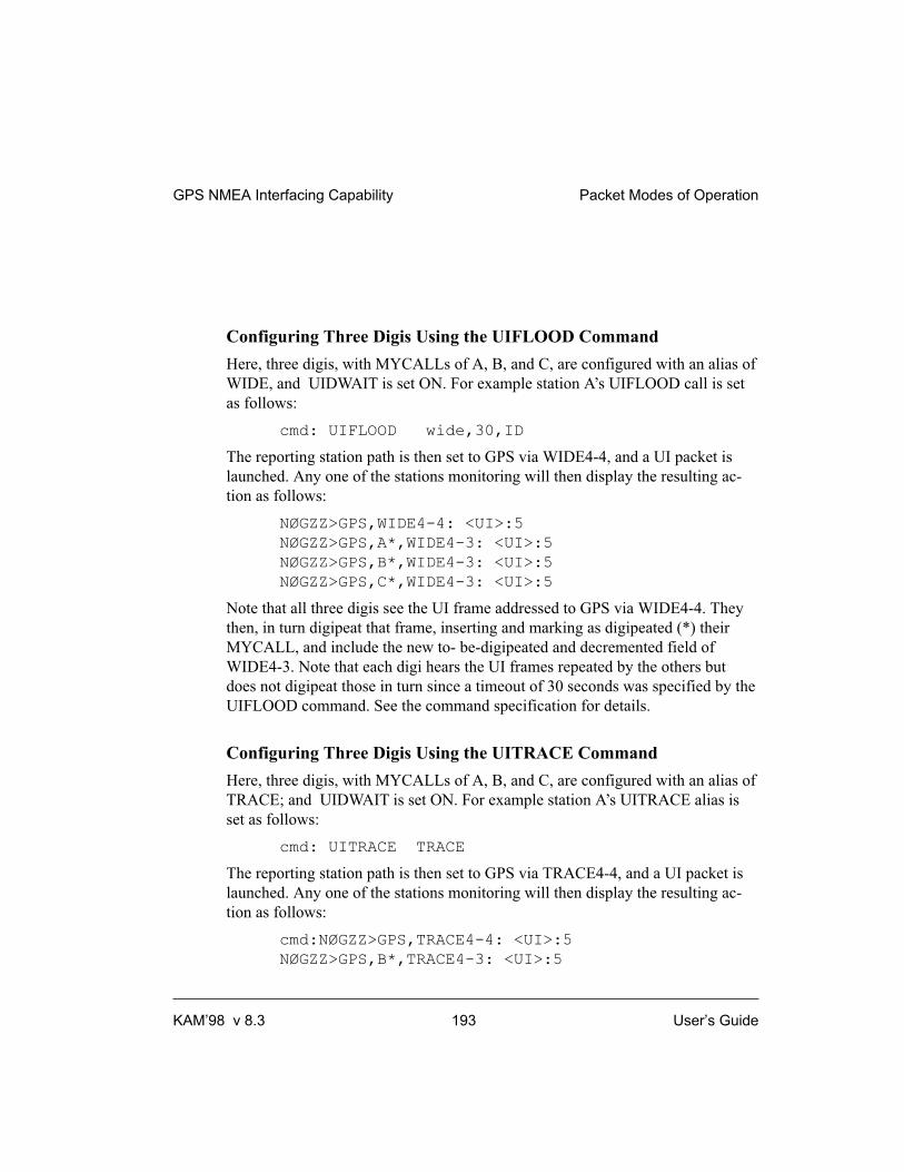
Configuring Three Digis Using the UIFLOOD Command
Here, three digis, with MYCALLs of A, B, and C, are configured with an alias of
WIDE, and UIDWAIT is set ON. For example station A’s UIFLOOD call is set
as follows:
cmd: UIFLOOD wide,30,ID
The reporting station path is then set to GPS via WIDE4-4, and a UI packet is
launched. Any one of the stations monitoring will then display the resulting ac-
tion as follows:
NØGZZ>GPS,WIDE4-4: <UI>:5
NØGZZ>GPS,A*,WIDE4-3: <UI>:5
NØGZZ>GPS,B*,WIDE4-3: <UI>:5
NØGZZ>GPS,C*,WIDE4-3: <UI>:5
Note that all three digis see the UI frame addressed to GPS via WIDE4-4. They
then, in turn digipeat that frame, inserting and marking as digipeated (*) their
MYCALL, and include the new to- be-digipeated and decremented field of
WIDE4-3. Note that each digi hears the UI frames repeated by the others but
does not digipeat those in turn since a timeout of 30 seconds was specified by the
UIFLOOD command. See the command specification for details.
Configuring Three Digis Using the UITRACE Command
Here, three digis, with MYCALLs of A, B, and C, are configured with an alias of
TRACE; and UIDWAIT is set ON. For example station A’s UITRACE alias is
set as follows:
cmd: UITRACE TRACE
The reporting station path is then set to GPS via TRACE4-4, and a UI packet is
launched. Any one of the stations monitoring will then display the resulting ac-
tion as follows:
cmd:NØGZZ>GPS,TRACE4-4: <UI>:5
NØGZZ>GPS,B*,TRACE4-3: <UI>:5
GPS NMEA Interfacing Capability Packet Modes of Operation
KAM’98 v 8.3 193 User’s Guide

NØGZZ>GPS,A*,TRACE4-3: <UI>:5
NØGZZ>GPS,B,A*,TRACE4-2: <UI>:5
NØGZZ>GPS,C*,TRACE4-3: <UI>:5
NØGZZ>GPS,B,C*,TRACE4-2: <UI>:5
NØGZZ>GPS,A,C*,TRACE4-2: <UI>:5
NØGZZ>GPS,B,A,C*,TRACE4-1: <UI>:5
NØGZZ>GPS,C,A*,TRACE4-2: <UI>:5
NØGZZ>GPS,B,C,A*,TRACE4-1: <UI>:5
NØGZZ>GPS,A,B*,TRACE4-2: <UI>:5
NØGZZ>GPS,C,B*,TRACE4-2: <UI>:5
NØGZZ>GPS,A,C,B*,TRACE4-1: <UI>:5
NØGZZ>GPS,C,A,B*,TRACE4-1: <UI>:5
NØGZZ>GPS,C,B,A*,TRACE4-1: <UI>:5
NØGZZ>GPS,A,B,C*,TRACE4-1: <UI>:5
All digis hear the first UI frame and store it. Due to the setting of UIDWAIT,
some stations may wait longer than others to digipeat; hence, when they do, they
may have several frames stored up - for example, the original and a digipeat from
another station. Trace station B as an example. It digis first, decrementing the
TRACE address to TRACE4-3; however, it does not digi again until nine UI
frames later, when it repeats a digi from A and decrements TRACE to
TRACE4-2. Since there are only three digipeaters in our example system,
TRACE4-1 is the last digi address noted.
Configuring Digis for HF/VHF Gateway Operations
+ This example assumes the use of at least one multi-port TNC that supports both
HF and VHF operation at the same time.
In this example, we demonstrate cross-band (gateway) digipeating, using selected
Kantronics TNCs. A UI frame is launched on HF and repeated on VHF four
times. A KAM Plus and two KPC-3 Pluses (with call signs C, B, and D) are con-
figured as digipeaters and another KAM Plus (call sign A) is set to launch a UI
frame from its HF port. The digis are configured with an alias of FLOOD and
UIDWAIT is set ON. In addition, MYGATE for digi C (the KAM Plus) is set to
C-3 and its UIGATE is set ON/OFF; that is, it is enabled to digi from HF to VHF
but not from VHF to HF. The KAM Plus, with call sign A, is then used to initiate
Packet Modes of Operation GPS NMEA Interfacing Capability
User’s Guide 194 KAM’98 v 8.3

an unproto packet with the path GPS via C-3, FLOOD4-4. Either KAM Plus will
then display the resulting action as follows:
A>GPS,C-3,FLOOD4-4/H: <UI>:234
A>GPS,C-3*,FLOOD4-4/V: <UI>:234
A>GPS,D*,FLOOD4-3/V: <UI>:234
A>GPS,C*,FLOOD4-2/V: <UI>:234
A>GPS,B*,FLOOD4-3/V: <UI>:234
Station C hears the HF unproto packet of station A and digipeats it via its GATE-
WAY out its VHF port. Digis B and D hear the VHF UI packet and store it for
digipeating, and D transmits first. In turn station C hears station D’s repeat of the
frame and digipeats the frame, decrementing flood to “FLOOD4-2.” It didn’t
digipeat its own “FLOOD4-4" frame because it can’t hear itself! Station B fin-
ishes last due to the slot/persist algorithm. D digipeats the frame only once even
though it hears both B’s and C’s transmissions since they are within 30 seconds
of it’s own transmission.
New In the KAM’98
Compared to previous Kantronics’ TNCs, the KAM’98 improves GPS function-
ality in several ways.
Using a Second Serial Port
A second read-only serial port, configured in firmware, is supported at pin 3 of
the AUX port of the KAM’98. This second read-only port accepts NMEA strings
from most GPS portables and frees up the KAM’98 RS-232 standard serial port
for connection to a laptop. This configuration eliminates the need for a special
cable, such as the Kantronics HSP, to accommodate the sharing of the RS-232 se-
rial port between a GPS device and a computer.
With this second port, the KAM’98 can be configured as part of a GPS tracker -
GPS device, TNC, and transceiver - and at the same time accommodate automati-
cally the attachment of a computer for sending/receiving packet data. For exam-
ple, the KAM’98 with GPS device attached to the second serial port will allow a
program such as APRS to take control of transmitting fix locations via UI frames.
This may be handy when a driver wishes to add his computer to a tracker already
operating in his vehicle.
GPS NMEA Interfacing Capability Packet Modes of Operation
KAM’98 v 8.3 195 User’s Guide

When the second serial port is activated, using the GPSPORT command, the
NMEA data input must be cabled to pin 3 of the auxiliary port (AUX) of the mo-
dem, rather than the RS-232 serial port. Wiring to the AUX port is straightfor-
ward; you must simply attach the two wires coming from the GPS device to the
port connector. Wire the NMEA+ wire to pin 3 and the NMEA- wire
to pin 6, ground (of the DB-9 connector). In addition, you must configure jumper
J9, just behind the AUX connector on the pc board, with the jumper on the center
pin and pin 2 (center and to the right side when looking from the back of the
unit).
The KAM’98 is configured for GPS tracker operation in the normal manner, as
outlined the previous sections. When using the second port for attachment of the
GPS device (instead of the normal serial port), the only setup changes required
are to turn on and configure this port, using the GPSPORT command. The
GPSPORT command allows you to configure a baud rate of 300, 600, 1200,
2400, or 4800 for the GPS device, use normal or inverted data, and use or not use
checksums sent by some NMEA strings. If GPSPORT is set to a baud rate of “0,”
then the port is disabled.
Example
The following example goes through the steps of setting up a tracker using the
Magellan Meridian XL GPS unit and the KAM’98.
1. Set up the modem parameters for GPS operation in the usual manner:
GPSHEAD 1 $GPRMC
LTP 1 GPS VIA RELAY, WIDE
BLT 1 EVERY 00:10:00 CLEAR
LTRACK 5 LT1 TIME
GPSTIME VALID RMC
MONITOR ON
2. Then configured the GPSPORT for 4800 baud operation, normal signaling,
and to check data input using checksums:
GPSPORT 4800 NORMAL CHECKSUM
These commands complete the parameter configuration of the KAM’98 as a
tracker with the GPS device attached to the AUX read-only serial port.
Packet Modes of Operation GPS NMEA Interfacing Capability
User’s Guide 196 KAM’98 v 8.3

+ Note: You do NOT have to change the interface command (INTface) to GPS
since the GPS device is not attached to the RS-232 port in this tracker configura-
tion. Second, it is necessary to configure jumper J9 to the center pin and pin 2.
This jumper setting routes the signal coming from pin 3 into the processor.
3. With the tracker set up and running - Magellan feeding the firmware port of
the KAM’98 - with a computer attached to the RS-232 serial port, with a basic
terminal program running, and with the packet MONITOR command and moni-
tor transmission (MXMIT) command on, beaconed RMC strings look like this:
W0XI>GPS: <UI>:
$GPRMC, 200257,A,3858.07,N,09518.09,W,00.0,000.0,040798,04,E*5D.
Time and data accuracy
Data and time accuracy for GPS tracker operations are improved with the
KAM’98. The firmware features the option of clearing of the location text buffers
after each beacon and the verification of checksums of the fix strings if they were
included in the NMEA-0183 strings received.
With the CLEAR option in the beacon location text (BLT) command, one has the
option of not beaconing if a new NMEA string is not received. If one was not re-
ceived but the location text buffer is still full, not CLEARED after the last bea-
con, “old” data will be beaconed. With the clear feature only fresh and valid data
is beaconed. This is optional, of course, as in some applications one might want
to beacon the last location known.
With the gpstime command (GPSTIME), one has the option of not setting the
KAM’98 clock unless a fresh string has been received that has a correct
checksum. Using this option in conjunction with the clear option for the location
text buffers, one can be assured that a beacon will not go out that does not have a
satellite based updated UTC time stamp.
GPS NMEA Interfacing Capability Packet Modes of Operation
KAM’98 v 8.3 197 User’s Guide

Bibliography
For more information on the Global Positioning System, we recommend the fol-
lowing resources:
General Information
Bruninga, Bob, WB4APR, “Automatic packet reporting system (APRS)”, 13th
ARRL Digital Communications Conference Proceedings, 1994. (address: ARRL,
225 Main Street, Newington, CT, 06111)
Sproul, Keith, WU2Z, “MacAPRS”, 13th ARRL Digital Communications Confer-
ence Proceedings, 1994.
Technical Information
Collins, J., et al., GPS Theory and Practice, Second Edition, Springer-Verlag, 1993.
Etherington, Michael, “FM subcarrier network extends differential GPS nationwide”,
Mobile Radio Technology, February 1994.
Kaplan, Elliot, “The global positioning system (GPS)”, Communications Quarterly, Sum-
mer 1994.
Langley, R., “The mathematics of GPS”, GPS World Magazine, July/August 1991.
“NMEA 0183 ASCII Interface Standard”, (NMEA 0183 version 2.0), NMEA, P.O. Box
50040, Mobile, AL 36605.
Packet Modes of Operation GPS NMEA Interfacing Capability
User’s Guide 198 KAM’98 v 8.3

KA-Node
Overview
Most Kantronics TNCs (e.g., KPC-3 Plus, KPC-9612 Plus) include, as a part of
their firmware, the Kantronics KA-Node, a packet networking node. If you turn
this node on, others may use your station (unattended) not only as a digipeater
but as a node, enabling them to find pathways to other stations and making those
pathways more efficient.
KA-Nodes, like other networking nodes such as NET/ROM, operate more effi-
ciently than do digipeaters as a link between two stations. End-to-end acknowl-
edgement of received packets is not required with the nodes; instead they handle
errors beween each other, rather than from end to end (which can cause extra
traffic when errors or interference occurs). A KA-Node, however, is “silent” in
that it does not automatically connnect to and exchange routing data with adja-
cent nodes, as do fully-features nodes such as NET/ROM, X1J, or Kantronics op-
tional K-Net. Consequently, users cannot issue a connect to a distant station
without knowing the path - as they sometimes can with a fully-featured node. At
the same time, KA-Nodes are useful in that they are more efficient than
digipeaters in using channel time, while not requiring the effort and time required
to maintain a full node.
When packet got started in the early 1980s, the initial packet units - terminal
node controllers (TNCs) - were designed and coded not only to accept sta-
tion-to-station connects, but to act as digipeaters for other stations. It was the
first
attempt at packet radio networking, linking two stations together via several oth-
ers. It soon became evident, however, that digipeating, particularly through busy
channels, was an inefficient method of linking two stations via others. First of all,
the station initiating the “connect” had no way to know ahead of time whether or
not the digipeating stations were available. Second, the AX.25 protocol called for
the station being connected to - at the end of several digipeaters - to acknowledge
each packet of the initiating station. Packets not acknowledged (due to collisions)
had to be retransmitted by the initiating station AND ALL DIGIPEATERS in the
communications chain. As a result, communication often ground to a halt when
channels were busy.
KA-Node Packet Modes of Operation
KAM’98 v 8.3 199 User’s Guide

To solve these problems, NET/ROM, a PROM-based networking program that
installed inside some TNC models, and a number of derivatives of NET/ROM
(e.g., G8BPQ, X1J, KA-Node, K-Net) were developed. These networking pro-
grams provide the user connecting to a station via one of these nodes with a
choice of pathways to other packet stations and with lists of stations heard.
NET/ROM and several of its derivatives provide for automatic routing of your
connect request - much like the phone system today routes your long distance
calls. Others, such as the KA-Node, assist you in building a pathway by allowing
you to connect to each node in turn through the pathway. All of the nodes correct
the “end-to-end” acknowledgment problem mentioned above. This is accom-
plished by building the pathway with a number of individual “local” connecting
links; that is, each link in the pathway is considered a connect and all acknowl-
edgments of packets are kept local. Hence, if only one link of a pathway (chain)
is troublesome, the local nodes take care of it.
The following material is provided to assist you in configuring your KA-Node
and telling others how to connect to and use it. A listing of the node commands
for users follows.
Configuring Your KA-Node
The following commands are used to configure your KA-Node: NUMNODES,
MYNODE, NDWILD, and KNTIMER.
In order to set your TNC for use as a KA-Node several conditions must be met.
First, you must allocate the number of circuits (channels) you wish to allow
through the KA-Node (see NUMNODES). Each circuit consists of an “IN” and
an “OUT” side. Secondly, the callsign assigned to the KA-Node (MYNODE)
must be different from the callsign used for you (MYCALL), your alias
(MYALIAS), the PBBS (MYPBBS), and remote access (MYREMOTE). By de-
fault, your TNC has set MYNODE to your callsign with an SSID of -7.
+ To cause your KA-Node to accept a connect request to any SSID of the
MYNODE callsign (except those mentioned above), set the NDWILD command
ON.
Packets passing through your KA-Node are monitored unless your MYNODE
callsign is included in the SUPLIST, if turned ON. If it becomes necessary to dis-
connect a station from your KA-Node, you can issue the command DISCON-
Packet Modes of Operation KA-Node
User’s Guide 200 KAM’98 v 8.3

NECT MYNODE x (x = channel) from the local terminal connected to your
TNC.
If no data passes through an established (connected) KA-Node circuit for n min-
utes, where n is set by “KNTIMER”, then that circuit will be disconnected. The
default time is 15 minutes but you can disable this by setting n to 0.
Each KA-Node circuit allowed will require approximately 4.3K of memory. If
you attempt to set NUMNODES to a value requiring more memory than avail-
able, you will receive a message indicating that the value is out of range. The to-
tal number of circuits which may be allocated will also be affected by the amount
of memory allocated to the Personal Mailbox.
+ Some Kantronics TNCs, such as the 9612 Plus, are multi-port. These multi-port
KA-Nodes can support cross-connects, Xconnects; that is, users may connect on
one port and then connect out another port, which may be attached to another
radio set to a different frequency.
Using a KA-Node
+ The material that follows is meant for those using your KA-Node, i.e. connecting
to it. You may use this material as a guide to using someone else’s node or in
connecting to your own node from another location (car, another station, via a
digi, etc.).
To use the KA-Node as a means of connecting to some other node or end-user,
you must first connect to the KA-Node. At the cmd: prompt on your TNC, issue
a connect request to the callsign of the KA-Node, let’s say it’s been named LAW.
When you make connection you will see the following messages on your display:
*** CONNECTED TO LAW
### CONNECTED TO WILD NODE LAW (NØGZZ) CHANNEL A
ENTER COMMAND B,C,J,N,X, or Help ?
The *** CONNECTED message is sent by your local TNC to your terminal, and
the ### CONNECTED TO NODE message comes from the distant KA-Node.
NØGZZ is the MYCALL of the station containing the KA-Node in this example,
WILD indicates that he is running a “wildcard” node, and CHANNEL A indi-
cates that you have connected to its channel A. If A is in use, you may obtain
channel B. The channels, or circuits, are assigned by the KA-Node as needed.
KA-Node Packet Modes of Operation
KAM’98 v 8.3 201 User’s Guide

After connecting to the KA-Node, you are in CONVERS mode at your own sta-
tion, and the KA-Node is waiting for a command. You issue a command to the
node by STAYING IN CONVERS MODE.
Note: The KA-Node will interpret the data you send as its commands.
At this point, let’s assume that you wish to know what other KA-Nodes are
nearby. You would issue the NODES command by typing N, or NODES, in re-
sponse to the KA-Node “enter command” prompt. You will receive a list of
KA-Nodes which have recently been heard. For example, let’s suppose that KC
was heard by LAW. Your list received from the Nodes command would be:
KC (NØAPJ-2) 12/23/87 02:38:45
ENTER COMMAND B,C,J,N,X, or Help ?
KC denotes the KA-Node callsign (MYNODE), the MYCALL of the KA-Node
station is in parentheses, followed by date and time heard. If LAW had heard
nothing, it would respond with:
NO KNOWN NODES
You may, instead, wish to know what other stations the KA-Node has heard
lately. This would be accomplished by sending a J for the JHEARD command.
The node will respond by listing its own MHEARD log. The list will contain end
user and node callsigns and is the same type of list you get by using your own
MHEARD command at the cmd: prompt.
At this point, let’s suppose that you would like to connect to the node called KC
through your current connection with LAW. Just issue a connect request to KC as
follows in response to the “enter command” from LAW:
CONNECT KC
The response will be:
###LINK MADE
###CONNECTED TO NODE KC (NØAPJ-2) CHANNEL A
ENTER COMMAND B,C,J,N,X, or Help ?
At this point you are “patched” through the KA-Node LAW to the node KC.
When LAW issued the connect request to KC it used your own call but sub-
tracted a count of one from your SSID. For example, if you connected to LAW
Packet Modes of Operation KA-Node
User’s Guide 202 KAM’98 v 8.3

with WØXI, LAW connected (via your request) to KC with WØXI-15. This is
automatic.
At this point, you could connect to another KA-Node, some other network node
using AX.25 as an uplink or downlink protocol, or to an end-user. Let’s assume
that you desire to connect to NØKN. So, just enter in response to the node “enter
command” above:
C NØKN STAY
and you’ll get the response:
###LINK MADE
+ We’ll explain the “STAY” later.
You are now connected to NØKN. If you have issued a connect command to a
KA-Node, and realize that you have made a mistake with the call, or for any
other reason wish to cancel the connection, you may do so by using the ABORT
command. In order for the abort to work, it MUST be the first word entered fol-
lowing the connect command and must be spelled out entirely. For instance if
you tell the KA-Node:
C KB5EEG
and then decide to abort the connect, your next entry must be:
ABORT
Any other entry will cancel any possible abort of the connection, and you must
wait for the KA-Node to retry out (e.g., because it will try to connect to
KB5EEG).
Now that you are connected to NØKN, you can carry on a normal packet QSO.
While everything appears “normal” and AX.25 compatible, acknowledgments to
your packets are generated by the KA-Node directly connected to you. Each link
in the chain/pathway takes care of its own errors. In other words, the link be-
tween KC and LAW handles its own error checking. In this way, one weak link
will not cause end-to-end packets and acknowledgments to be repeated as they
would with digipeating. The result is substantial improvement in throughput for
connections using nodes.
KA-Node Packet Modes of Operation
KAM’98 v 8.3 203 User’s Guide

When it comes time to disconnect, you do so in the standard AX.25 manner. To
disconnect the link described above, type <Ctrl+C>, obtain the cmd: prompt on
your TNC, and issue the disconnect command:
cmd: D
***DISCONNECTED
You’ll get the usual disconnect message from your TNC, as noted. If however,
your distant partner, in this case NØKN, disconnects the link, you’ll see the fol-
lowing (due to the “STAY” in “C NØAPJ STAY” in the example earlier):
###DISCONNECTED BY NØAPJ AT NODE KC
ENTER COMMAND B,C,J,N,X, or Help ?
Frequently when connecting to a distant city, you may wish to talk to more than
one station. Perhaps when you connected, you got a message saying “I’m not
here right now, please leave a message in my PBBS”. By using the “S(tay)”
option when telling a KA-Node to connect to another station, the KA-Node will
not disconnect from you if it receives a disconnect from the distant station. In-
stead, you will receive a message from the KA-Node saying ###DISCON-
NECTED BY (call) AT NODE (MYNODE). In other words, if you connected
from Lawrence, Kansas to a KA-Node in Lincoln, Nebraska, and then told that
KA-Node to connect to someone using the command “C call Stay”. Then if that
station sent you the above message and disconnected, you would remain con-
nected to the KA-Node in Lincoln! This would allow you to issue a connect di-
rectly to his BBS, without having to re-establish the entire path.
In multiple KA-Node paths, each time you say B(ye) to the distant KA-Node,
this will return you to the next previous KA-Node which had been told to “Stay”
in the chain of KA-Nodes. From that point, you could build a path in a different
direction. One point to note here is that if you use the KA-Node to connect to a
BBS (WØRLI or WA7MBL for instance), and use the STAY option, then say
B(ye) to the BBS, you would remain connected to the KA-Node closest to the
BBS. If you issue the connect without the STAY option, any disconnect from ei-
ther end will cause the entire link to disconnect.
Packet Modes of Operation KA-Node
User’s Guide 204 KAM’98 v 8.3

Automatic Disconnect
If a user abandons a connection to a KA-Node or a link between two KA-Nodes
without disconnecting and there is no activity through the link for a specified pe-
riod of time (see KNTIMER), the node will initiate a disconnect.
Using the XCONNECT Command
Note: The XCONNECT command is available only on Kantronics’ multi-port
TNCs, such as the KPC-9612 Plus. Single-port TNCs (e.g., KPC-3 Plus) do not
support this command, but they may connect to a KA-NODE that does.
The cross-connect (XCONNECT) command is a unique feature of the KA-Node.
This command allows cross linking between two frequencies through the node in
much the same manner as the Kantronics unique gateway, but with local ac-
knowledgment of packets.
For example, suppose you just connected to node LAWKAN and wish to
cross-connect to NØGZZ whose station is tuned to the frequency of the other
port of the node. Just issue X NØGZZ following the the node prompt:
ENTER COMMAND B,C,J,N,X, or Help
X NØGZZ <CR>
The response you receive will be:
### LINK MADE
### CONNECTED TO NØGZZ
You can also determine from the response to the NODE command, which port a
node is on. Below is an illustration of a KA-Node response to a NODE com-
mand:
LAWKAN* 12/02/87 15:45:00
N66046/X 12/02/87 15:49:15
OLAKAN/X 12/02/87 16:15:21
In this typical display, the callsign of the node is given, followed by the date and
time it was last heard. The “/X” indicates that the node was heard on the opposite
port from the one you are connected on. The asterisk (*) means that the node was
heard via a digipeater.
KA-Node Packet Modes of Operation
KAM’98 v 8.3 205 User’s Guide

Determining Which Port You Have Connected To
When you are connected to a multi-port node, you can determine which port you
are on, at the node, by using the JHEARD command. A typical node response to
the JHEARD command may appear on your display as shown (the KAM uses /H
and /V instead of /1 and /2):
N66046/2* 12/01/87 14:32:69
NØKN-1/1 12/01/87 16:25:01
WØXI/2 12/02/87 16:28:05
NØGZZ/1 12/02/87 16:32:09
In this illustration the number following the slash (/) indicates the port the station
was heard on. Your callsign will usually be the last one in this list.
You can now see that by comparing the port on which your call appears in the
JHEARD list to the port indicated for other stations, you can determine whether
to CONNECT or XCONNECT to the station of your choice.
KA-Node Commands for Remote Use
When accessed by radio, the KA-Node supports several commands which may
be given to it. These commands are listed here for reference, with a description of
each command. In these descriptions, the UPPER case characters of the com-
mand are required, while LOWER case characters are optional. Those items
listed within [ ] are optional and if used the UPPER/LOWER case convention
applies.
ABORT
Aborts a KA-Node Connect or Xconnect request if it is the first data sent after
the connect request. It must be spelled out entirely.
Bye
Causes the KA-Node to initiate a disconnect.
Packet Modes of Operation KA-Node
User’s Guide 206 KAM’98 v 8.3

Connect callsign [Stay]
Causes the node to issue a connect request to “callsign” in the usual AX.25
mode. If the connect is successful, a link will be made to the next node or
end-user station called. The optional Stay feature provides a way to disconnect
without loosing the entire link. Normally when a disconnect occurs, whether is-
sued by you or by the remote station, the connection to the KA-Node is also lost.
Using the Stay option allows you to stay connected to the KA-Node when the re-
mote station issues a disconnect.
Help
Causes the KA-Node to send a brief help list, showing all commands available,
with the options and a short description of each command.
Jheard [Short|Long]
Causes the KA-Node to transmit its MHEARD log. The returned list (without the
short or long option) may look like this:
(HF/VHF Multi-Port)
LAWKAN/H* 01/09/88 08:25:15
N66046/V 01/10/88 00:03:10
NØKN-3/H 01/10/88 00:03:19
NØGZZ/V 01/10/88 00:04:15
(VHF/UHF Multi-Port)
LAWKAN/1* 01/09/88 08:25:15
N66046/2 01/10/88 00:03:10
NØKN-3/1 01/10/88 00:03:19
NØGZZ/2 01/10/88 00:04:15
(Single-Port)
LAWKAN 01/09/88 08:25:15
N66046* 01/10/88 00:03:10
NØKN-3 01/10/88 00:03:19
NØGZZ 01/10/88 00:04:15
KA-Node Packet Modes of Operation
KAM’98 v 8.3 207 User’s Guide
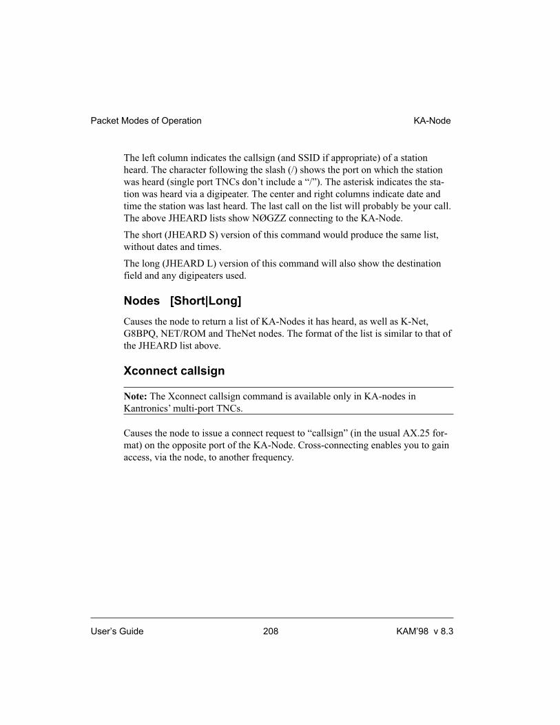
The left column indicates the callsign (and SSID if appropriate) of a station
heard. The character following the slash (/) shows the port on which the station
was heard (single port TNCs don’t include a “/”). The asterisk indicates the sta-
tion was heard via a digipeater. The center and right columns indicate date and
time the station was last heard. The last call on the list will probably be your call.
The above JHEARD lists show NØGZZ connecting to the KA-Node.
The short (JHEARD S) version of this command would produce the same list,
without dates and times.
The long (JHEARD L) version of this command will also show the destination
field and any digipeaters used.
Nodes [Short|Long]
Causes the node to return a list of KA-Nodes it has heard, as well as K-Net,
G8BPQ, NET/ROM and TheNet nodes. The format of the list is similar to that of
the JHEARD list above.
Xconnect callsign
Note: The Xconnect callsign command is available only in KA-nodes in
Kantronics’ multi-port TNCs.
Causes the node to issue a connect request to “callsign” (in the usual AX.25 for-
mat) on the opposite port of the KA-Node. Cross-connecting enables you to gain
access, via the node, to another frequency.
Packet Modes of Operation KA-Node
User’s Guide 208 KAM’98 v 8.3

Other Modes of Operation
Other ways of using your TNC are covered in this section.
+ Some of the following modes of operation require special software, so they may
not be available if you are using standard terminal programs such as Pacterm and
Procomm Plus.
Remote Sensing and Control
You can use two (or more) packet radio stations, each containing a Kantronics
TNC, to implement remote sensing and/or remote control, as follows:
• remote control of another TNC: from a local Kantronics TNC-based
radio station, use the MYREMOTE command to establish control of a
remote Kantronics TNC-based radio station and issue commands for the
remote TNC to carry out. For details, see the Command Reference.
• sense analog inputs: use the ANALOG command to gather and report
the status of one or two analog input lines in the remote TNC.
Kantronics single port and multi-port TNCs contain an 8 bit A/D
converter and additional circuitry that converts the analog voltage
presented at two specified inputs into digital values from 0 to 255. You
can then use these digital values (reported in binary) as an approximation
of the analog voltage values at the time the TNC interrogated the analog
inputs. For details on the ANALOG command, see the Command
Reference.
+ Note: As documented in the ANALOG command and the radio port pin
spefications, single port devices and multiport devices use different input
lines and ports for analog sensing.
• control output voltages: use the CTRL command to control the voltages
on selected output lines in the remote TNC (up to two output lines in
single port devices and four output lines in multi-port devices). Each of
these output lines can be set to 5 volts (i.e., ON) or 0 volts (i.e., OFF) by
the CTRL command. Also, the CTRL command can be used with any or
all of these output lines to send a specified number of short ON/5
volts-then-OFF/0 volts pulses (each pulse lasting about .1 second, with
Other Modes of Operation Packet Modes of Operation
KAM’98 v 8.3 209 User’s Guide

a fixed length pause between pulses) or a single long (about 1.5 second)
ON/OFF pulse. For details on the CTRL command, see the Command
Reference.
+ You can also use the ANALOG and/or CTRL commands, without the REMOTE
command, to carry out sensing and control functions at a local Kantronics TNC.
The following diagram illustrates the use of two Kantronics TNC/radio stations
for remote control and sensing. These operations could be carried out manually
or via a terminal program running in the computer in the central TNC station.
As noted earlier, the Command Reference sections and sections of pin assigments
provide details needed to adapt these broad capacities to your own situation, with
your own sensors, controls, and remote locations.
Packet Modes of Operation Other Modes of Operation
User’s Guide 210 KAM’98 v 8.3
Pum p
Dra in
Too Full
Full
Pre ssureSensor(for le ve lof liquid )
LIQUID
Tank
Centra lKa ntronic sTNC Ba sedSta tion
Rem oteKa ntronic sTNC Ba sedSta tion
Remote Sensing and Control
OPERATING RULES for c ontrolling the le ve l of the liquid :1. If the le ve l is "low" or le ss, turn the Pum p ON.2. If the le ve l is "full" or m ore, turn the Pum p OFF.3. If the le ve l is "too full" or m ore, OPEN the Dra in.4. If the le ve l is "full" or le ss, CLOSE the Dra in.
ra d ioc onnec tionbe tween TNCs
Control line 1 (ON/OFF)
Control line 2 (OPEN/CLOSE)
A/D n li 1se sor ne
Exa m p le : c ontrolling the le ve l of liquid in a ta nk
Low

ASCII Mode (1200 Baud)
Copying Weather Broadcasts NWS EMWIN
ASCII mode (1220 baud) mode can be used to copy emergency weather broad-
casts by the National Weather Service. The NWS Emergency Managers Weather
Information Network (EMWIN) is a wireless direct-to-computer information ser-
vice that the National Weather Service (NWS) provides with help from the Fed-
eral Emergency Management Agency. The NWS feeds a constant stream of
weather information (@ 1200,8,N,1), from around the world, to a satellite orbit-
ing the Earth. Many cities are coming on line now to capture this stream and
rebroadcast it on fixed VHF commercial FM frequencies just above the 2-meter
ham band.
Using your TNC in ASCII mode, with a PC and communications software, you
can copy these broadcasts. The content of the broadcasts may be plain ASCII text
(copyable with Pacterm - shipped with Kantronics TNCs) or graphics (copyable
with “WeatherNode” software, not carried by Kantronics). Interpretation of the
content of the products is up to the software. For updated information on
EMWIN and software to copy its modes, search the Internet.
To copy the broadcasts, simply cable together the equipment mentioned above,
tune your VHF FM receiver to the local EMWIN frequency, set the TNC to
ASCII mode, and follow the text on your PC screen.
+ Note: Some computers may lose some of the data stream if a full RS-232 cable is
used. This can occur because the RS232 CD line, which is “tied” to the TNC’s
receive LED, may be cycling up and down. In this case, set CD to EXTERNAL.
Kantronics Host Mode Operation
Kantronics’ Host Mode allows your TNC to communicate with computer soft-
ware that is more sophisticated than standard terminal programs such as
Pacterm. Software, such as Kantronics’ HostMaster II+, that supports this mode
will automatically set your TNC INTFACE command to HOST mode and per-
form a soft reset.
Your host program will provide you with some means to give commands to the
TNC. For a complete description of your host program, refer to the manual that
comes with your software.
Other Modes of Operation Packet Modes of Operation
KAM’98 v 8.3 211 User’s Guide

+ After you switch to HOST mode, your TNC will remain in HOST mode until you
switch to COMMAND mode. The easiest way to switch out of HOST mode is to
use your host mode software (see instructions with that software). If you begin
using Pacterm while the TNC is in HOST mode, you will see the message
“ SØØ ”, sent by the TNC to indicate that it is in HOST Mode. If you see this
message, you must first exit the Host Mode before you can start talking to your
unit with a program such as Pacterm. You must send three characters to the TNC
in order to exit the Host Mode and go back to COMMAND mode. First, send a
FEND character (ASCII code 192), then the letter q (upper or lower case is ok),
and finally another FEND character. Your TNC will then leave Host Mode,
switch to COMMAND mode, and send the usual Kantronics sign-on message. If
you use a terminal program other than Pacterm, it may send these characters au-
tomatically, or it may require that you carry out this same procedure to get out of
HOST mode and to COMMAND mode. See Appendix D for details on this pro-
cedure.
KISS Mode
Amateur packet radio communications can use the TCP/IP suite of protocals in-
stead of AX.25 by switching to KISS mode and running software that supports
the KISS code designed by Phil Karn (see references at end of this section). The
KISS protocol specifies the communication between a TNC and a host (e.g.,
computer).
KISS Mode allows the TNC to act as a modem and packet assem-
bler/disassembler (PAD). In KISS Mode, data-processing is shifted from the
TNC to a computer running special software supporting the KISS code designed
by Phil Karn. KISS code supports higher level protocols (i.e. TCP/IP) for sharing
computer resources in a network fashion. Examples of TCP/IP programs are
NET, NOS, and JNOS. Also, some networking software (G8BPQ) requires the
KISS Mode of operation.
Packet Modes of Operation Other Modes of Operation
User’s Guide 212 KAM’98 v 8.3

Technical Note: In the KISS Mode, the TNC simply passes all received data to your
computer, and the computer program is responsible for all processing of that data,
including decisions concerning routing, digipeating, and other control decisions.
The TNC converts the packets of synchronous data being received from the radio
link into packets of asynchronous data to be passed to the computer over the serial
port, and converts the packets of asynchronous data from your computer into the
synchronous format suitable for radio transmission. The TNC retains the responsi-
bility of determining proper timing for channel access.
To place your TNC in KISS Mode, you must first have the command prompt
(cmd:). Then type INTFACE KISS and press return. And, finally, do a RESET.
After that you will not see any message or any prompt back from the TNC, it will
now be in KISS mode.
If you turn your unit off while it is it INTERFACE KISS mode, it will still be in
KISS mode when you turn it back on. To get out of KISS mode, either:
• perform a hard reset, or
• use the TCP/IP command (available in KISS software while in KISS
mode), or
• send the C0 FF C0 sequence from your keyboard.
To send the C0 FF C0 sequence from your keyboard (using a PC compatible
computer):
1. Press and HOLD the ALT key. Type the numbers 192 from the numeric
KEYPAD, not the keyboard. Release the ALT key.
2. Press and HOLD the ALT key. Type the numbers 255 from the numeric
KEYPAD, not the keyboard. Release the ALT key.
3. Press and HOLD the ALT key. Type the numbers 192 from the numeric
KEYPAD, not the keyboard. Release the ALT key.
If the terminal program you are using sent all those characters, you will be out of
the KISS Mode now.
References on KISS Mode
Other Modes of Operation Packet Modes of Operation
KAM’98 v 8.3 213 User’s Guide

Karn, P.: “TCP/IP: A Proposal for Amateur Packet Radio Levels 3 and 4",
pp. 4.62-4.68 ARRL Amateur Radio Computer Networking Conferences 1-4.
Newington, CT: ARRL, 1985.
Chepponis, M. and Karn, P.: “The KISS TNC: A Simple Host-to-TNC
Communications Protocol”, pp. 38-42, 6th Computer Networking Conference,
Newington, CT: ARRL, 1987.
XKISS (Extended KISS) Mode
The TNC also supports the G8BPQ multi-drop KISS Mode, called extended
KISS (XKISS) . With this mode, the TNC can be connected to a G8BPQ node
along with the other TNCs on the same serial port, to provide multiple radio ports
to the node. Otherwise, XKISS works like KISS. For information on this mode of
operation, see the documentation for the XKISS software you are using.
Packet Modes of Operation Other Modes of Operation
User’s Guide 214 KAM’98 v 8.3
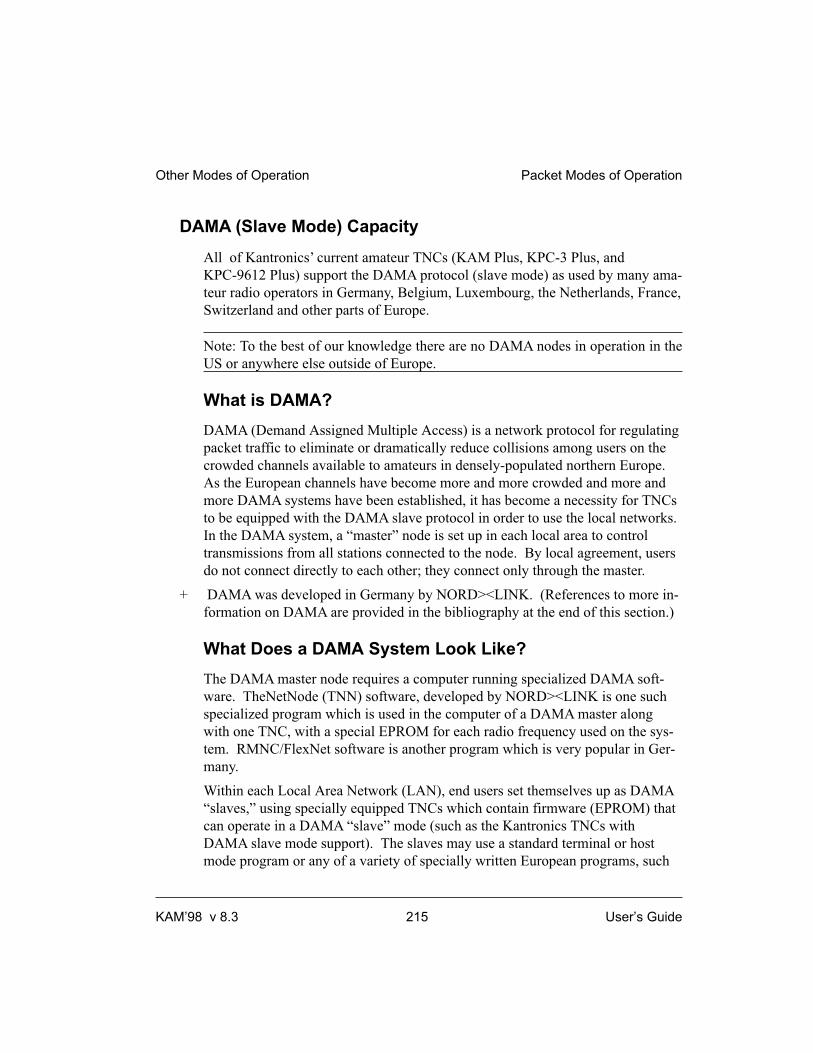
DAMA (Slave Mode) Capacity
All of Kantronics’ current amateur TNCs (KAM Plus, KPC-3 Plus, and
KPC-9612 Plus) support the DAMA protocol (slave mode) as used by many ama-
teur radio operators in Germany, Belgium, Luxembourg, the Netherlands, France,
Switzerland and other parts of Europe.
Note: To the best of our knowledge there are no DAMA nodes in operation in the
US or anywhere else outside of Europe.
What is DAMA?
DAMA (Demand Assigned Multiple Access) is a network protocol for regulating
packet traffic to eliminate or dramatically reduce collisions among users on the
crowded channels available to amateurs in densely-populated northern Europe.
As the European channels have become more and more crowded and more and
more DAMA systems have been established, it has become a necessity for TNCs
to be equipped with the DAMA slave protocol in order to use the local networks.
In the DAMA system, a “master” node is set up in each local area to control
transmissions from all stations connected to the node. By local agreement, users
do not connect directly to each other; they connect only through the master.
+ DAMA was developed in Germany by NORD><LINK. (References to more in-
formation on DAMA are provided in the bibliography at the end of this section.)
What Does a DAMA System Look Like?
The DAMA master node requires a computer running specialized DAMA soft-
ware. TheNetNode (TNN) software, developed by NORD><LINK is one such
specialized program which is used in the computer of a DAMA master along
with one TNC, with a special EPROM for each radio frequency used on the sys-
tem. RMNC/FlexNet software is another program which is very popular in Ger-
many.
Within each Local Area Network (LAN), end users set themselves up as DAMA
“slaves,” using specially equipped TNCs which contain firmware (EPROM) that
can operate in a DAMA “slave” mode (such as the Kantronics TNCs with
DAMA slave mode support). The slaves may use a standard terminal or host
mode program or any of a variety of specially written European programs, such
Other Modes of Operation Packet Modes of Operation
KAM’98 v 8.3 215 User’s Guide

as SP, Grafik Packet and ESKAY, some of which make use of the KISS mode
feature of the TNC.
To use the DAMA system, the user connects to the DAMA master with a normal
connect frame. When the master responds to the connect frame, the TNC is auto-
matically placed into DAMA slave mode. The DAMA master polls each slave
within the LAN in a “round-robin” fashion (somewhat like the token passing
method) and the slave TNCs transmit packets when the master has granted per-
mission to do so. The slave TNCs continue to be polled with priority among the
slaves assigned according to the number of times each responds with information
frames (as opposed to rr frames - i.e., no data to send). Priority is dynamically
assigned so that those stations that are sending information are polled more fre-
quently than idle stations. However, once an “idle” station responds with infor-
mation, its priority is upgraded.
Communication over the wider area is handled between the DAMA master nodes
which are connected to each other using a standard NET/ROM™ type protocol.
For the DAMA system to work effectively, each slave associates with only one
master node and connects only to that master. If an end user is connected to
more than one master, each master will poll the slave TNC according to its poll-
ing schedule. When polled, the slave TNC will transmit all frames it has avail-
able to whichever master polls it. This would increase the probability of
collisions with other users, thus defeating the purpose of the DAMA system.
How is DAMA Implemented in Kantronics TNCs?
Most Kantronics TNCs, including the KPC-3 Plus, KPC-9612 Plus, and the
KAM Plus, implement the DAMA slave mode, using the following commands
(see the Command Reference section for details):
DAMA {ON|OFF}
Set DAMA to ON to have your Kantronics TNC operate as a DAMA slave sta-
tion once a connection is established with a DAMA master station. When
DAMA is OFF, the TNC will operate in it’s carrier sense multiple access mode
(CSMA). For details, see the CD, SLOT, and PERSIST commands in the Com-
mand Reference section of this manual.
Packet Modes of Operation Other Modes of Operation
User’s Guide 216 KAM’98 v 8.3

DAMACHCK n (n = 0 to 225)
Set a “DAMA time-out” timer (in 10-second increments) to specify how long
your TNC (running in DAMA slave mode) will wait to be polled by a connected
DAMA station before disconnecting from the DAMA station and reverting to
CSMA operation .
Bibliography
Bertrem, Eric, F5PJE. “RMNC/FlexNet: The Network of Choice in Western Europe.” In “Packet
Perspective” conducted by Stan Horzepa WA1LOU. QST April 1995: 88.
Jost, Gunter, DK7WJ, Sonnabend, Joachim, DG3FBL, and FlexNet-Group. “FlexNet. The Euro-
pean Solution”. Proceedings of the 9th Computer Networking Conference. American Radio Relay
League, Newington, CT, USA 06111.
Medcalf, Karl, WK5M. “DAMA - Another Network Solution.” Proceedings of the 14th Computer
Networking Conference. American Radio Relay League, Newington, CT, USA 06111.
Rech, Wolf-Henning, N1EOW/DF9IC and Kneip, Johannes, DG3RBU. “The German (Central Eu-
ropean) Packet Radio Network: An Overview.” Proceedings of the 11th Computer Networking
Conference. American Radio Relay League, Newington, CT, USA 06111.
Schmid, Detlef J., DK4EG. “DAMA - A New Method of Handling Packets?” Trans. Mark
Bitterlich, WA3JPY. Proceedings of the 8th Computer Networking Conference. American Radio
Relay League, Newington, CT, USA 06111. Published in German as “DAMA, ein neues Verfahren
für Packet Radio?” cq-DL April 1989.
TheNetNode (TNN) Copyright 1994, NORD><LINK e.V., c/o Klaus-Dieter Vieth, Goergesstrasse 3, D-38118
Braunschweig, Germany. NET/ROM is a trademark of Software 2000, Inc.
Other Modes of Operation Packet Modes of Operation
KAM’98 v 8.3 217 User’s Guide

CAUTION! The DAMA firmware in Kantronics’ TNC is based on documentation published in the
ARRL Computer Networking Conference papers (see Bibliography) and documentation provided
by NORD><LINK, the developers of DAMA. This firmware was tested with TheNetNode firm-
ware (Version 1.56), TFKISS (Version 2.0) and by volunteer testers in Europe with firmware used
in existing DAMA networks. Kantronics cannot be responsible for subsequent changes to the
DAMA protocol which may render this firmware obsolete nor guarantee satisfactory operations
with newer versions of the protocol and/or complementary software.
Packet Modes of Operation
User’s Guide 218 KAM’98 v 8.3

Command Reference
Introduction
This chapter documents all KAM’98 commands.
There are many commands which affect operation of the KAM’98. Some com-
mands affect performance under specific conditions, some change parameters af-
fecting general operation and others direct a one-time action.
The user changes parameters and issues instructions to the KAM’98 by typing
commands composed of English-like word abbreviations and variables which are
numbers or strings of characters chosen by the user. You will probably never
change some of these parameters.
Default values are stored in permenant memory (i.e., in an EPROM). If you
change any setting or value, the new setting or value will be stored in bat-
tery-backed RAM and will be the value used at future power-on.
The availability of the commands listed here depends upon what INTFACE
(i.e., INTERFACE) mode the KAM’98 is currently in (see the INTFACE
command in the command listing below and check the index for more informa-
tion on INTFACE modes).
Format for Listing Commands
All KAM’98 commands are listed alphabetically below.
A “�” bullet in front of the name of a command indicates that the command is a
NEWUSER Command — it will be available for use when the KAM’98 is set to
NEWUSER Mode.
The KAM’98 ships with NEWUSER as the default INTFACE mode. Also, the
KAM’98 will be in NEWUSER mode after a hard reset.
KAM’98 v 8.3 219 User’s Guide

Format Defining Commands
The Command Line
The first line of each command definition shows the syntax for entering the com-
mand, beginning with the name of the command, followed by a listing of any pa-
rameters that may be used with the command.
The full name of each command is shown in CAPS and a “short-form” of the
command is shown by the underlined characters in the name. The short-form of
the command is the shortest string of characters, starting from the beginning of
the full name, that will allow the KAM’98 to uniquely identify the command be-
ing requested.
The KAM’98 scans an internal list of commands — which is NOT in alphabetical
order — and selects the first match with the string you enter.
The command name is followed by a space.
After the space, there may be one or more parameters that need to be used, or that
may optionally be used, with the command.
• Values that need to be entered as they are shown (or by using the
short-form indicated by the underlined character(s)) are shown in CAPS ,
as in “ON | OFF”. Parameter names for which a value needs to be
substituted are shown in lower case letters, as in “callsign,” which means
a particular callsign needs to be entered.
• Lists of parameter values are enclosed in curly brackets “{ }” for
grouping clarity and lists of optional parameter values are enclosed in
square brackets “[ ]”.
• If more than one choice is possible for the value of a given parameter
(i.e., flag), choices are separated by a vertical bar, as in “ ON | OFF” or
“OPTION1 | OPTION2 | OPTION3".
If a parameter can take a range of values (or in cases such as ABAUD, any of a
set of numerical values) the parameter is shown as a name in lower case (e.g.,
“n”) and the permissible range of values ( or the list of possible values) is given
in parentheses “( )” to the right side of the command, after the syntax has been
Command Reference Introduction
User’s Guide 220 KAM’98 v 8.3

presented. For example, possible values of the parameter “n” are defined as
“(n = 1 - 255)”.
The Line Below the Command Definition
If commands have parameters, default values are shown on the line below the
command definition.
Some KAM’98 commands take effect immediately, so they are called “immedi-
ate” commands (e.g., K means “switch to CONVERSE mode"). This will be
stated on the second line. For example, the command to go to CONVERS mode
says “immediate” on the second line.
More Information on Commands
Each command is explained in detail and examples are given where appropriate.
Following the explanation of the command, there may be a “See also” list that
shows related commands.
Parameter Types
Almost all parameters are of one of the following types (exceptions are discussed
when they are encountered in the command listing).
n (range)
Any number within the range is permissible. The unit of measure (seconds, ms,
baud, count, etc.) for the number will be given in the description. These are deci-
mal numbers.
n ($00 - $FF)
Special functions: Some parameters are used to control special functions, such as
specifying the character to use to enter the Command mode from the Convers
mode or specifying the character to use for “backslash”. Possible values and de-
fault values for these parameters are shown in HEX format.
The “digits” of a hex number represent powers of 16, analogous to the powers of
10 represented by a decimal number. The decimal numbers 10 through 15 are
represented in hex by the letters A through F (e.g., decimal 10 is hex A). And a
hex number is distinguished from a decimal number by preceding it with a “$”
prefix.
Introduction Command Reference
KAM’98 v 8.3 221 User’s Guide

For example:
$1B = (1*16) + 11 = 27
Number codes for these special characters are shown in hexadecimal (hex) form
(i.e., base 16). They can be entered either in decimal or in hex. Permissible val-
ues are shown in HEX: for example (n = $00 - $FF).
Note: Setting a function character to zero ($00) disables that function.
+ See the ASCII Chart at end of this manual for a listing of ASCII codes for all
alphanumeric characters, including A to Z and 0 to 9, and conversions between
hex and decimal representations.
Several parameters are ASCII numerical values for characters which perform
special functions. Most of these special function characters have “control charac-
ters” as default values. Control characters are entered by holding down a special
control key (normally marked “Ctrl”) on the keyboard while typing the indicated
key. For example, to enter a <Ctrl+X>, hold down the Control key while typing
an X, then release both keys.
+ These special characters cannot be sent in a packet unless preceded by the pass
character (see the PASS command) or unless you are operating in the Transparent
Mode.
If a streamswitch (STREAMSW) character or any other special character is defined
as “$” then you will need to enter values in decimal, or precede the $ with the PASS
character in order to enter hex numbers.
flags ChoiceA|ChoiceB
Many parameters are “flags”, meaning they have two possible values, ON and
OFF, or YES and NO. All of the command descriptions show ON and OFF as the
options; however YES (Y) and NO (N) may be typed instead. A few parameters
are really flags, but rather than indicating that something is “on” or “off”, they
select one of two ways of doing things. Some of these parameters have the values
EVERY or AFTER indicating operating modes for data transmission.
The possible choices are separated by a vertical bar. Some of the flag parameters
will allow many choices, such as ON|OFF|TO|FROM.
Command Reference Introduction
User’s Guide 222 KAM’98 v 8.3

callsigns xxxxxx-n
Several commands require callsigns as parameters. While these parameters are
normally Amateur callsigns, they may actually be any collection of numbers
and/or letters up to six characters; they are used to identify stations sending and
receiving packets. A callsign may additionally include an “extension” (SSID,
Secondary Station Identifier), which is a decimal number from 0 to 15 used to
distinguish two or more stations on the air with the same Amateur call (such as a
base station and a repeater). The callsign and extension are entered and displayed
as call-ext, e.g. NØGZZ-3. If the extension is not entered, it is set to -0, and ex-
tensions of -0 are not displayed by the KAM’98.
text
There are some commands which have a parameter text string. This string can be
any combination of letters, numbers, punctuations, or spaces up to 128 charac-
ters. In order to be used, all string parameters must contain at least one non-space
character. You can even put characters with special meanings, such as carriage re-
turn, into the string by preceding them with the PASS character. The string ends
when you type a (non-passed) carriage return.
Entering Commands
To enter a command, the KAM’98 needs to be in COMMAND Communication
Mode (as opposed to CONVERS or TRANS communication mode).
The prompt for Command Mode is:
cmd:
+ Hint: Once you go into Packet Convers Mode a <Ctrl+C> (see COM-
MAND) needs to be entered to return you to the Command Mode. In the
Packet Transparent Mode or GPS Mode, a special sequence is needed to
return to Command Mode (see CMDTIME).
Introduction Command Reference
KAM’98 v 8.3 223 User’s Guide

+ Hint: If packets have been printing on the screen you may have forgotten
which mode you are in. If you wish to see the cmd: prompt type a
<Ctrl+C>, to see if you are already in Command Mode. If the prompt
does not appear then you are either in Command Mode or in Transparent
Mode. If you are in Command Mode, typing a Return will generate the
“cmd:” prompt. If you are in Transparent Mode, you will not get the
“cmd:” prompt when you press the Return key; instead, you need to enter
three <Ctrl+C>s in rapid succession to switch to the Command Mode
and get the “cmd:” prompt.
When you are at the Command Mode prompt, you enter a command for the
KAM’98 by typing the command name (in upper or lower case) and any re-
quired and optional parameter values (argument settings or values).
+ The command name and each parameter value must be separated from each other
by at least one space.
To ENTER the command press the carriage return “CR” (usually an ENTER
key). As soon as the “CR” key is pressed, the KAM’98 will process the com-
mand request and take whatever action is specified (or inform you with an “EH?”
if it does not understand what you have entered).
As noted above, you can enter the short-form of a command name — the charac-
ters underlined in the listing.
The short form is not necessarily the shortest unique string in the name or the first
match in alphabetical order — rather it is the first match that the KAM’98 will find
as it scans through the non-alphabetical listing of commands in its EPROM.
+ Hint: You can examine the value of any parameter by typing the command name
followed by a “CR”. A special command, DISPLAY, allows you to see the values
of all parameters or groups of related parameters.
Command Reference Introduction
User’s Guide 224 KAM’98 v 8.3

KAM’98 Commands
All KAM’98 commands are documented below, in alphabetical order. The under-
lined characters in a command’s name show the short-cut version of the com-
mand. Required or optional parameters are shown after the command name, as
are allowable ranges of values, where appropriate.
8BITCONV {ON | OFF}
default ON
+ This command was added to the first TNCs built (1980s) to accommodate termi-
nals that would not receive (or would be confused by) 8-bit characters, only 7-bit
ASCII. We’ve retained the command today just in case you’re using such a ter-
minal or computer. Also, it might be that your computer is capable of handling
8-bit characters but your communications terminal program will reject (or be
confused or “hung”) by them. In these cases, you’ll need to set 8BITCONV OFF.
When ON, transmission of 8-bit data is allowed in the packet Convers Mode and
Transparent Mode. If you wish to obtain 8-bit data transmission but do not want
all the features of Transparent Mode, set this command to ON. If OFF, the 8th
data bit is stripped (set to 0) for transmission and all data received will have the
8th bit set to 0. This does not affect the KA-Node, digipeat or PBBS functions.
ABAUD n (n = 0,300, 600,1200,2400,4800,
9600,19200,38400)
default 0
The parameter n sets the baud rate used for input and output through the serial
RS232 port of the KAM’98 to the computer. If 0 is used, the KAM’98 will run an
autobaud routine upon power-up. This routine looks for an asterisk (*) character
from the attached computer to set the ABAUD parameter.
If you wish to use a different baud rate, or to perform autobaud the next time the
unit is powered up, you must change the ABAUD parameter. If you change the
baud rate in your computer or terminal you should change the baud rate in the
KAM’98 Commands Command Reference
KAM’98 v 8.3 225 User’s Guide

KAM’98 first, then issue the RESET command, then set the new baud rate on
your computer. Otherwise a hard reset will be required to erase the ABAUD set-
ting and reinitialize the KAM’98 to perform the autobaud routine. (See Hard Re-
set section.) Note also that a hard reset will erase ALL stored parameters in your
KAM’98 and return them to factory defaults.
See also: reset, restore
AMTOR {xxxx{xxxxx}}
immediate
This command places the KAM’98 in the AMTOR STANDBY mode. Entering
AMTOR xxxx[xxxxx] (i.e., selcal) will cause the KAM’98 to start a link se-
quence to the station specified.
+ Selcal format (the “xxx” character string) depends upon which version of
AMTOR you are using (see Modes of Operation section).
Entering AMTOR without a selcal will allow your KAM’98 to respond to a link
request from another station, monitor for free signals sent from shore stations, or
to transmit Mode B (FEC) AMTOR. To transmit Mode B, type <Ctrl+C>T to be-
gin transmission, and type <Ctrl+C>E to end transmission. You may also copy
Mode B transmissions in this mode, if ARQBBS is OFF.
This command is also used to enter standby mode or to initiate a link request
when working in SITOR mode with a commercial shore station (such as WLO or
Globe Wireless) to send HF e-mail. The AMTOR code in the KAM’98 is com-
patible with its commercial cousin, titled SITOR. For more detail, see HF E-Mail
in the non-packet modes of operation section.
See also: arqid, arqtime, autostrt, canline, cwid, fec, freequal, lamtor, misschar,
mygroups, myselcal, pmode, rephase, txdtor, txdfec.
ANALOG
immediate
Command Reference KAM’98 Commands
User’s Guide 226 KAM’98 v 8.3

Entering the ANALOG command returns a string of 8 values, based on the cur-
rent voltage readings from 8 A-to-D lines. Only the first four of these values are
relevant to the user, reporting up to four external voltages.
At any given time, each of the 8 A-to-D lines will have a voltage value some-
where in the range of 0 - 5 VDC. Instead of reporting voltages, the ANALOG
command returns a decimal number in the range of 0 - 255 for each line. Each
decimal value corresponds to a voltage input in the range of 0 to +5 VDC.
The reason ANALOG returns 8 values is that it is attached to an 8-way mux input of
a single A/D converter. In the KAM’98, only the first four values are relevant to the
user (several other lines could be used for special purposes, with appropriate modi-
fications of the board, but they are normally intended just for internal use within
the KAM’98).
The response is in the form “AN0/AN1/AN2/AN3/AN4/AN5/AN6/AN7",
where:
• AN0, input (0), reports a decimal number in the range of (0-255),
representing the current DC voltage of an external input read from pin 1
on the AUX Port.
• AN1, input (1), reports a decimal number in the range of (0-255),
representing the current DC voltage of an external input read from pin 2
on the AUX Port.
• AN2, input (2), when jumper J9 is in position 1, reports a decimal
number in the range of (0-255), representing the current DC voltage of
an external input read from pin 3 of the AUX port.
+ When jumper J9 is in position 2, this A-to-D input is connected to in-
ternal circuitry and the value of AN2 has no significance to the user.
• AN3, input (3), when jumper J21 is in position 2, reports a decimal
number in the range of (0-255), representing the current DC voltage of
an external input read from pin 4 of the AUX port.
+ When jumper J21 is in position 1, this A-to-D input is connected to
internal circuitry and the value of AN3 has no significance to the
user.
KAM’98 Commands Command Reference
KAM’98 v 8.3 227 User’s Guide

Measuring voltages greater than +5V. As noted above, the A-to-D convert-
ers associated with AN0 through AN3 convert analog voltages from 0 to +5 V
to digital values from 0 through 255. Thus, input voltages greater than +5 V
would all receive the same digital value, yielding little useful information.
However, it is possible to use AN0 through AN3 to measure (digitize and re-
port) voltages as great as +50V (the maximum external voltage for the device)
by adding appropriate voltage dividers to scale the range of input voltages
down to fit within the range measured by the A-to-D converters. This is accom-
plished by installing appropriately valued resistors in the blank resistor posi-
tions provided on the PC board (i.e., positions labeled R4, R8, R3, and R13, for
AN0, AN1, AN2, and AN3, respectively).
• AN4, AN5, AN6, and AN7 (inputs 4-7) are connected to internal
circuitry and the readings have no significance to the user.
+ AN7 can be used to report the state of an external TTL (0 or 5 volt)
signal connected to pin 2 on the Radio port, as long as the user is
willing to give up the normal use of this pin, which is as an external
carrier detect input.
Kantronics recommends that users not cut lines associated with AN4 through
AN7 for adapting them for measuring additional A-to-D inputs.
+ Data can be gathered from a remote site by connecting to MYREMOTE and then
issuing the ANALOG command.
See also: myremote
ARQBBS {ON | OFF}
default OFF
When ON, the PBBS in your KAM’98 may be accessed by another station using
AMTOR,G-TOR, or Pactor ARQ. When OFF, the PBBS may only be accessed
on packet.
Command Reference KAM’98 Commands
User’s Guide 228 KAM’98 v 8.3

+ Note: if ARQBBS is ON, you will not be able to transmit FEC from the Standby
modes.
See also: arqid, pbbs.
ARQID n (n = 0 - 31)
default 9
This command sets the time interval in 1 minute increments for an automatic CW
ID when operating AMTOR, G-TOR, or Pactor ARQ. The CW ID will be trans-
mitted at the speed set by the CWSPEED command, and the text of the ID is set
with the CWIDTEXT command. Setting ARQID to 0 disables the automatic ID.
See also: arqbbs, cwid.
ARQTIME n (n = 1 - 10)
default 2
This command sets the timeout interval when attempting to link to another sta-
tion in AMTOR ARQ mode. The interval is set in increments of 64 ARQ cycles
(approximately 28.8 seconds).
See also: amtor.
ASCBAUD n (n = 20 - 500)
default 110
This command sets the default baud rate used when entering the ASCII mode
with no baud rate specified.
See also: ascii.
KAM’98 Commands Command Reference
KAM’98 v 8.3 229 User’s Guide

ASCII [n] (n = 20 - 1200)
immediate
This command places the KAM’98 in ASCII mode. If you specify the optional
value n, the KAM’98 will enter ASCII at the specified speed; otherwise it will
operate at the speed set in ASCBAUD.
Note: When switching from 300 baud packet operation on HF to 1200 baud packet
operation on VHF/UHF, remember to change the following (HF defaulted) parame-
ters: Mark, Space, SWP, Slottime, Persist, Maxframe, Paclen, Hbaud. See the
packet section in the modes of operation chapter for further detail (page 144).
See also: ascbaud, autostrt, canline, hbaud, pmode.
AUTOCR n (n = 0 - 255)
default 0
A carriage return <CR> character is sent to the radio after n characters are typed
on a line when operating RTTY, ASCII, AMTOR, G-TOR, or Pactor. Setting
AUTOCR to 0 disables automatic carriage returns.
AUTOLF {ON | OFF}
default ON
When ON, a line feed is sent to the terminal after each carriage return. This pa-
rameter should be set on when overprinting occurs and the terminal being used
does not automatically supply its own linefeed after a carriage return. This com-
mand affects only the data sent to the terminal, not data sent to the radio.
See also: cr, lfadd
Command Reference KAM’98 Commands
User’s Guide 230 KAM’98 v 8.3

AUTOSTRT {ON | OFF}
default OFF
When ON and operating in RTTY or ASCII mode, the KAM’98 will receive in-
formation only after it has received the MYAUTOST identifier. It will then con-
tinue to receive until it receives four “N”s signifying the end of message, or 30
seconds of no signal.
When ON and in AMTOR mode or FEC mode, only AMTOR SELFEC mes-
sages which contain any of the selcals in MYSELCAL or MYGROUP will be re-
ceived. Loss of lock will cause the KAM’98 to stop receiving data.
See also: fec, myautost, mygroup, myselcal.
AX2512V2 {ON | OFF}
default ON
This command provides compatibility with all known packet units implementing
AX.25 protocol. When ON, Level 2 Version 2 protocol is implemented and the
TNC will automatically adapt to whichever version the connecting station is us-
ing. When OFF, Level 2 Version 1 is implemented. Set this command to OFF if
you need to digipeat through other units which do not digipeat version 2 packets.
You may also find benefit from setting this command OFF when using several
digipeaters (not nodes) to send packets, or when conditions are marginal between
the two stations involved. (NOTE: Changing this setting after connecting to an-
other station will have no effect on the current connection.)
The major difference in V1 and V2 protocol is the method used to handle retries.
In the connected mode, if a packet is sent and not acknowledged, Version 1 will
re-send the entire packet and then disconnect if the RETRY count is reached.
Version 2 will first send a poll, the response to this poll will determine if the
packet was received. It is possible that the ack was collided with and therefore
the data packet does not need to be resent. If the ACK shows that the data packet
was not received, it will be re-transmitted. Each time a poll is answered the
TRIES count is reset to 0. If the RETRY count is reached, version 2 will attempt
KAM’98 Commands Command Reference
KAM’98 v 8.3 231 User’s Guide
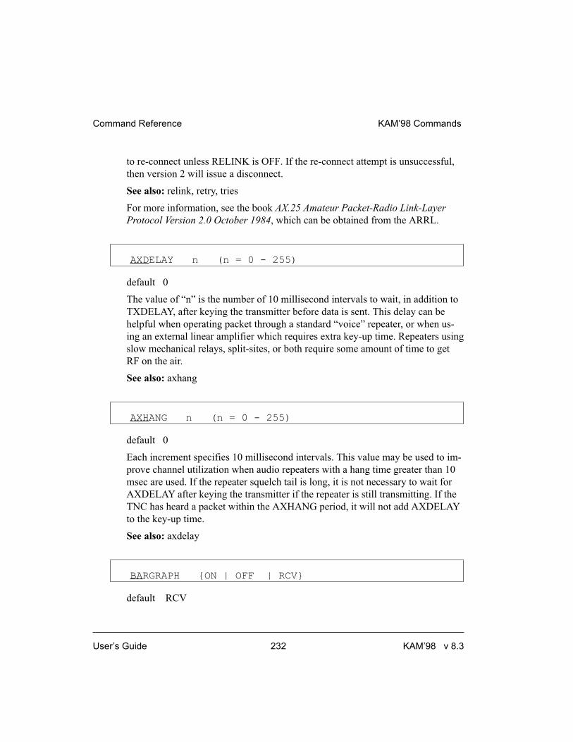
to re-connect unless RELINK is OFF. If the re-connect attempt is unsuccessful,
then version 2 will issue a disconnect.
See also: relink, retry, tries
For more information, see the book AX.25 Amateur Packet-Radio Link-Layer
Protocol Version 2.0 October 1984, which can be obtained from the ARRL.
AXDELAY n (n = 0 - 255)
default 0
The value of “n” is the number of 10 millisecond intervals to wait, in addition to
TXDELAY, after keying the transmitter before data is sent. This delay can be
helpful when operating packet through a standard “voice” repeater, or when us-
ing an external linear amplifier which requires extra key-up time. Repeaters using
slow mechanical relays, split-sites, or both require some amount of time to get
RF on the air.
See also: axhang
AXHANG n (n = 0 - 255)
default 0
Each increment specifies 10 millisecond intervals. This value may be used to im-
prove channel utilization when audio repeaters with a hang time greater than 10
msec are used. If the repeater squelch tail is long, it is not necessary to wait for
AXDELAY after keying the transmitter if the repeater is still transmitting. If the
TNC has heard a packet within the AXHANG period, it will not add AXDELAY
to the key-up time.
See also: axdelay
BARGRAPH {ON | OFF | RCV}
default RCV
Command Reference KAM’98 Commands
User’s Guide 232 KAM’98 v 8.3

When BARGRAPH is set to ON, the bargraph on the front panel of the KAM’98
is always turned ON. When BARGRAPH is set to OFF, the bargraph is always
turned OFF. When BARGRAPH is set to RCV, the bargraph is turned ON during
receive and OFF during transmit.
BEACON [EVERY | AFTER] n (n = 0 - 255)
default Every 0
The value entered for “n” is the number of minutes (i.e., one-minute intervals) to
use with the beacon command.
A value of 0 turns the beacon OFF. Setting a value greater than 0 activates the
beacon under the conditions specified. If the optional keyword Every is used, a
beacon packet will be sent every n minutes. If set to After, a beacon packet will
be sent ONCE after the specified interval with no channel activity.
The beacon frame consists of the text specified by BTEXT in a packet addressed
to “BEACON”. Beacon messages will be digipeated via any addresses specified
in the UNPROTO command.
See also: btext
BITS n (n = $00 - $FF)
default $00
This command specifies the bits to be inverted when receiving a (5 bit) RTTY or
(8 bit) ASCII signal. This may enable you to decode some RTTY/ASCII signals
that have some bits inverted. For example, setting BITS $F0 (bit pattern
1111000) would invert the first four bits of received ASCII or RTTY signals.
Transmitted RTTY and ASCII is not affected by this command.
� BKONDEL {ON | OFF}
default ON
KAM’98 Commands Command Reference
KAM’98 v 8.3 233 User’s Guide

When ON, the sequence backspace-space-backspace is sent to the attached termi-
nal when the DELETE character is entered. When OFF, the backslash character
“\” is sent to the terminal when the DELETE character is entered.
See also: delete, redisplay
BLT n {EVERY | AFTER} hh:mm:ss
[START hh:mm:ss] [CLEAR] (n = 1 - 4)
default EVERY 00:00:00 (for each of the 4 LT strings)
This command (used with GPS) sets the interval between beacons for the
associated LT (Location Text) string.
n identifies which LT is used (1-4). If EVERY is specified, the LT will be trans-
mitted at the interval specified by the hh:mm:ss parameter. This is set in
hours:minutes:seconds, and all characters must be specified. If the optional key
word START is given followed by a time (in 24 hour format), the beacons will
not be transmitted until the specified time. The beacon will then be transmitted
according to the setting of the EVERY parameter. (NOTE: If the current time is
past the start time, the beacon will start at the next scheduled interval based on
the start time.)
If AFTER is specified, the beacon will be transmitted once after no activity is de-
tected on the channel for hh:mm:ss time. Selecting AFTER does not allow the
optional START parameter.
For example, setting BLT 3 EVERY 00:15:00 START 03:30:00 would cause the
third LT string (LT 3) to be transmitted every 15 minutes, with the first transmis-
sion each day occurring at 03:30:00.
If CLEAR is specified, the LT buffer is cleared after transmission.
BREAK {ON | OFF}
default OFF
Command Reference KAM’98 Commands
User’s Guide 234 KAM’98 v 8.3

If BREAK is ON, a break at the keyboard causes a return to Command Mode
from Converse or Transparent Mode.
See also: COMMAND
BTEXT text (0 - 128 characters)
default (blank)
BTEXT specifies the content of the data portion of the beacon packet. Any com-
bination of characters and spaces may be used with a maximum length of 128.
Entering a single “%” will clear BTEXT.
See also: beacon
BUDLIST [ON|OFF] [NONE | {+|-}call | call1,call2,...]
where call={callsign | {<|>}callsign |
callsign{>|<>}callsign}
default OFF NONE
BUDLIST is used to determine which received packets will be monitored. When
OFF or NONE, BUDLIST will allow monitoring of all packets, even if it has
callsigns in it’s list.
The maximum number of callsigns allowed in BUDLIST is 10. Up to 10
callsigns may be entered at once, using the format shown after the command
name, and the new list of from 1 to 10 callsigns will replace whatever list was
there before. The BUDLIST command can be used to add a single callsign
(+callsign), so long as there is room for the new callsign on the list (if there is
not, the TNC responds with “EH?” and returns you to the command prompt).
Similarly, you can remove a single callsign (-callsign) from the list. And to re-
move all items from the current list, enter BUDLIST NONE.
A callsign entered without a SSID will match any SSID of that callsign. To match
a specific SSID only, enter the callsign with that SSID: for example, callsign-n,
where n = 0-15.
KAM’98 Commands Command Reference
KAM’98 v 8.3 235 User’s Guide
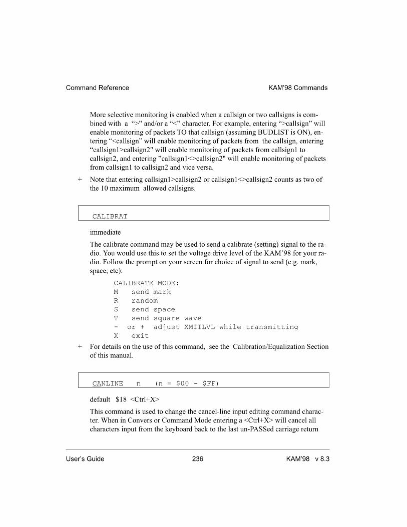
More selective monitoring is enabled when a callsign or two callsigns is com-
bined with a “>” and/or a “<” character. For example, entering “>callsign” will
enable monitoring of packets TO that callsign (assuming BUDLIST is ON), en-
tering “<callsign” will enable monitoring of packets from the callsign, entering
“callsign1>callsign2" will enable monitoring of packets from callsign1 to
callsign2, and entering ”callsign1<>callsign2" will enable monitoring of packets
from callsign1 to callsign2 and vice versa.
+ Note that entering callsign1>callsign2 or callsign1<>callsign2 counts as two of
the 10 maximum allowed callsigns.
CALIBRAT
immediate
The calibrate command may be used to send a calibrate (setting) signal to the ra-
dio. You would use this to set the voltage drive level of the KAM’98 for your ra-
dio. Follow the prompt on your screen for choice of signal to send (e.g. mark,
space, etc):
CALIBRATE MODE:
M send mark
R random
S send space
T send square wave
- or + adjust XMITLVL while transmitting
X exit
+ For details on the use of this command, see the Calibration/Equalization Section
of this manual.
CANLINE n (n = $00 - $FF)
default $18 <Ctrl+X>
This command is used to change the cancel-line input editing command charac-
ter. When in Convers or Command Mode entering a <Ctrl+X> will cancel all
characters input from the keyboard back to the last un-PASSed carriage return
Command Reference KAM’98 Commands
User’s Guide 236 KAM’98 v 8.3

(unless PACTIME has expired, CPACTIME is turned on, and you are in Convers
Mode).
See also: canpac, cpactime, pass
CANPAC n (n = $00 - $FF)
default $19 <Ctrl+Y>
This command is used to change the cancel-packet command character. When in
the Convers Mode entering a <Ctrl+Y> will cancel all keyboard input back to the
last unpassed SENDPAC character (unless PACTIME has expired and
CPACTIME is turned on).
This character also functions as a cancel-output character in Command Mode.
Typing the cancel-output character a second time re-enables normal output. For
example, if you’ve told the TNC to do a DISPLAY, a <Ctrl+Y> will cancel the
display and a second one re-enables the cmd: prompt after the next “CR”.
See also: canline, cpactime, sendpac
CD {INTERNAL | EXTERNAL | SOFTWARE}
default INTERNAL
The CD command selects which carrier detect method will be used.
When set to INTERNAL, the TNC will detect a signal present on the channel,
within the set bandwidth range, using an energy type carrier detect, allowing
shared voice and data on the same channel.
When set to EXTERNAL, the carrier detect is supplied by an external device,
connected to the XCD pin on the radio port. This device must pull the voltage
near ground to indicate carrier detect.
If set to SOFTWARE, the firmware inside the TNC will detect the presence of
data to enable the carrier detection, allowing operation with un-squelched audio.
KAM’98 Commands Command Reference
KAM’98 v 8.3 237 User’s Guide

+ Correct operation of SOFTWARE carrier detect is affected by proper equaliza-
tion and the SWP parameters. If your RCV light flickers, this is an indication that
you may need to adjust the equalization. (Equalization is set with an internal
jumper.)
When CD is set to INTERNAL or SOFTWARE, the external carrier detect pin on
the radio connector (if wired) is used to hold off the TNC from keying the radio.
+ Hint: For one use of this function, see the APRS and GPS section of this manual.
When operating RTTY or ASCII, the KAM’98 will use only INTERNAL or EX-
TERNAL. If this comand is set to SOFTWARE, the KAM’98 will act as though
it were set to INTERNAL when operating these modes.
See also: swp
CHECK n (n = 0 - 255)
default 0
This “timeout” command is used to prevent a “hang-up” in a connected mode
when a link failure occurs as a result of conditions beyond control of the con-
nected stations. The value entered for “n” is the number of 10 second intervals to
wait during “no activity” before making a periodic check (poll) to determine that
a connected state still exists.
If n equals 0, this “timeout” function is disabled. While using Version 1
(AX25L2V2 OFF), a check timeout will initiate a disconnect.
See also: ax25l2v2, kntimer, relink, rnrtime
CMDTIME n (n = 0 - 15)
default 1
This command sets the time allowed for entry of required characters to exit the
Transparent Mode. In order to allow exit to Command Mode from Transparent
Mode, while permitting any character to be sent as data, a guard time of
CMDTIME seconds is set up.
Command Reference KAM’98 Commands
User’s Guide 238 KAM’98 v 8.3

Entering a value for “n” sets the value of CMDTIME to “n seconds”.
To exit Transparent mode, you need to wait at least CMDTIME since the last
data character was sent to the KAM’98. Then you need to enter the COMMAND
character (e.g., <Ctrl+C>)) three times, with a wait of LESS THAN the value of
CMDTIME between the first and second time you enter the COMMAND charac-
ter and also a wait of LESS THAN the value of CMDTIME between the second
and third time you enter the COMMAND character.
After a final delay of CMDTIME the TNC will exit Transparent Mode and enter
Command Mode. At this time you should see the cmd: prompt. If CMDTIME is
set to zero, the only exit from Transparent Mode is a modem break signal, assum-
ing BREAK is set to ON.
For example (if CMDTIME is 1 second and COMMAND is <Ctrl+C>): wait one
second, type a <Ctrl+C>, within one second type a second <Ctrl+C>, within one
second type a third <Ctrl+C>, WAIT one second, cmd: prompt should appear. If
your computer/program has the capability you can also send a modem break to
escape Transparent Mode.
See also: command, trans, break
CMSG {ON | OFF | DISC | PBBS}
default OFF
When OFF, the custom connect text stored in CTEXT will not be sent to the con-
necting station upon receiving a connect request. When ON, the custom CTEXT
string will be sent. When CMSG is set to DISC, the custom CTEXT string will
be sent to the connecting station, and then your TNC will disconnect from that
station. If set to PBBS, the custom CTEXT string will be sent to the connecting
station, and then the connection will automatically be transferred to your PBBS.
If the PBBS is not available, your TNC will disconnect from the station.
See also: ctext, pbbs
KAM’98 Commands Command Reference
KAM’98 v 8.3 239 User’s Guide
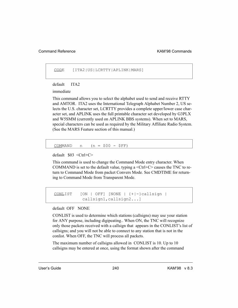
CODE [ITA2|US|LCRTTY|APLINK|MARS]
default ITA2
immediate
This command allows you to select the alphabet used to send and receive RTTY
and AMTOR. ITA2 uses the International Telegraph Alphabet Number 2, US se-
lects the U.S. character set, LCRTTY provides a complete upper/lower case char-
acter set, and APLINK uses the full printable character set developed by G3PLX
and W5SMM (currently used on APLINK BBS systems). When set to MARS,
special characters can be used as required by the Military Affiliate Radio System.
(See the MARS Feature section of this manual.)
COMMAND n (n = $00 - $FF)
default $03 <Ctrl+C>
This command is used to change the Command Mode entry character. When
COMMAND is set to the default value, typing a <Ctrl+C> causes the TNC to re-
turn to Command Mode from packet Convers Mode. See CMDTIME for return-
ing to Command Mode from Transparent Mode.
CONLIST [ON | OFF] [NONE | {+|-}callsign |
callsign1,callsign2...]
default OFF NONE
CONLIST is used to determine which stations (callsigns) may use your station
for ANY purpose, including digipeating.. When ON, the TNC will recognize
only those packets received with a callsign that appears in the CONLIST’s list of
callsigns; and you will not be able to connect to any station that is not in the
conlist. When OFF, the TNC will process all packets.
The maximum number of callsigns allowed in CONLIST is 10. Up to 10
callsigns may be entered at once, using the format shown after the command
Command Reference KAM’98 Commands
User’s Guide 240 KAM’98 v 8.3

name, and the new list of from 1 to 10 callsigns will replace whatever list was
there before. The CONLIST command can be used to add a single
callsign (+callsign), so long as there is room for the new callsign on the list
(if there is not, the TNC responds with “EH?” and returns you to the command
prompt). Similarly, you can remove a single callsign (-callsign) from the list.
And to remove all items from the current list, enter CONLIST NONE.
A callsign entered without a SSID will match any SSID of that callsign. To match
a specific SSID only, enter the callsign with that SSID: for example, callsign-n,
where n = 0-15.
CONMODE {CONVERS | TRANS}
default CONVERS
This command controls the mode the TNC will be placed in AUTOMATICALLY
after a connect if NOMODE is OFF. The connect may result either from a con-
nect request received or a connect request originated by a CONNECT command.
If the TNC is already in Convers or Transparent Mode when the connection is
completed, the mode will not be changed. If you have typed part of a command
line when the connection is completed, the mode change will not take place until
you complete the command or cancel the line input.
See also: canline, connect, convers, nomode, trans
� CONNECT call1 [VIA call2,call3,...,call9]
immediate
call1 = callsign of station to be connected to.
call2,...,call9 = optional stations to be digipeated through. A maximum of 8
digipeater addresses (callsigns or aliases) can be specified. This is referred to as a
path.
Each callsign may also have an optional Secondary Station Identifier (SSID)
specified as -n, where n = 1 - 15. The digipeat callsigns are specified in the order
KAM’98 Commands Command Reference
KAM’98 v 8.3 241 User’s Guide

in which they are to relay transmitted packets. The mode set by CONMODE will
be entered upon successful connect, if NOMODE is OFF. If no response to the
Connect request occurs after RETRY attempts, the command is aborted. A time-
out message is printed on the display and the TNC remains in the Command
Mode. The station being connected to (call1) may receive the connect request but
be unable to accept connects, in which case a busy message will be printed to the
screen and the TNC will stay in Command Mode. Connect requests may only be
initiated in the Command Mode and the connect will be established on the cur-
rent stream.
If a connect is in progress, or already established, the path may be changed by
simply re-issuing the CONNECT command with the desired path. This must be
done on the same stream as the original connect.
CAUTION, packets en route between your station and the reconnected station may
be lost.
If CONNECT is entered with no parameters, the status of the current stream is
displayed.
See also: conmode, conok, dbldisc, maxusers, nomode, retry, ring, streamsw, xmitok
CONOK {ON | OFF}
default ON
When ON, connect requests from other TNCs will be automatically acknowl-
edged and a <UA> packet will be sent. The standard connect message, with
stream ID if appropriate, will be output to the terminal and the mode specified by
CONMODE will be entered on the I/O stream if you are not connected to another
station and NOMODE is OFF.
When OFF, connect requests from other TNCs will not be acknowledged and a
<DM> packet will be sent to the requesting station. The message “connect re-
quest: (callsign of whoever is trying to connect to you)” will be output to your
terminal if INTFACE is TERMINAL or NEWUSER.
When CONOK is OFF, you can still connect to your mailbox.
Command Reference KAM’98 Commands
User’s Guide 242 KAM’98 v 8.3

When operating with multiple connects allowed, the connection will take place
on the next available stream. Connect requests in excess of the number allowed
by the USERS command will receive a <DM> response and the “connect re-
quest: (call)” message will be output to your terminal if INTFACE is TERMI-
NAL or NEWUSER.
See also: conmode, connect, intface, maxusers, monitor, nomode, users.
CONPERM {ON | OFF}
Default OFF
Setting CONPERM to ON forces the connection on the current stream to become
permanent and causes the KAM’98 to attempt to reconnect when it is restarted.
CONPERMED connections are shown with /P in the status display, which is gen-
erated by the STAT command.
See also: status
� CONVERS
immediate
CONVERS has no options. It is an immediate command and will cause entry into
Conversational Mode from Command Mode on the current I/O stream. Any link
connections are not affected.
+ Hint: K is the same as CONVERS, for quicker entry.
See also: k, command
CPACTIME {ON | OFF}
default OFF
When OFF and in the Convers Mode, packets are sent when the SENDPAC char-
acter is entered or when PACLEN is achieved. When ON and in the Convers
KAM’98 Commands Command Reference
KAM’98 v 8.3 243 User’s Guide

Mode, packets are sent at periodic intervals determined by PACTIME. Charac-
ters are sent periodically as in Transparent Mode but the local editing and echo-
ing features of Convers Mode are enabled.
See also: convers, cr, paclen, pactime, sendpac, trans
CR {ON | OFF}
default ON
When ON the SENDPAC character (normally carriage return) is appended to all
packets sent in Convers Mode except when PACLEN is exceeded. Setting CR
ON and SENDPAC $0D results in a natural conversation mode. Each line is sent
when a “CR” is entered and arrives at its destination with the “CR” appended to
the end of the line. To avoid overprinting, AUTOLF may need to be ON at the re-
ceiving end.
See also: autolf, lfadd, sendpac.
CRADD {ON | OFF}
default OFF
When ON, a carriage return will be added to every carriage return received from
your terminal before being transmitted in RTTY, ASCII, G-TOR, and Pactor.
When OFF, no extra carriage returns are added by the KAM’98.
See also: fladd.
CRSUP {ON | OFF}
default OFF
This command was added to the first multi-mode TNCs (such as the Kantronics
UTU and KAM) to accommodate the practice by radio teletype (RTTY) opera-
tors of adding an extra carriage return (CR) at the end of each line (i.e., CR, CR,
linefeed (LF) ). This was done to give the carriage of the old mechanical tele-
Command Reference KAM’98 Commands
User’s Guide 244 KAM’98 v 8.3

types time to return across the page. Some of these machines are still in use, so
we’ve retained this command so you can “correct” the data you might receive
from such a station. To do so, turn CRSUP ON. When ON, this command sup-
presses every other carriage return (when no data is between them) in the re-
ceived data before sending the data to the terminal. When CRSUP is OFF, all
carriage return characters are left in the received data as it is sent to the terminal.
See also: autolf, lfsup
CSTAMP {ON | OFF}
default OFF
When ON, the daytime stamp is printed with all “*** CONNECTED TO” and
“*** DISCONNECTED” messages on the terminal.
See also: connect, daytime, disconnect, mstamp
CTEXT text (0 - 128 characters)
default (blank)
Enter any combination of characters and spaces up to maximum length of 128.
Entering a single “%” will clear CTEXT. This entry specifies the text of the first
packet to be sent in response to an accepted connect request provided that the pa-
rameter CMSG is not OFF.
See also: cmsg, connect
CTRL [A | B] {OFF | ON | LONG | n | MUTE m}
(n=1-20) (M=1-9)
immediate
This command causes the KAM’98 to activate the specified output line (A or B)
to the radio port or AUX as indicated. If A or B output is not specified, both out-
puts are affected. For instance, to pulse the A output (CTRLA) 3 times, you
KAM’98 Commands Command Reference
KAM’98 v 8.3 245 User’s Guide

would give the command “CTRL A 3". You may optionally specify the number
of times to pulse the output (n), or to turn the output ON, or OFF. Each pulse on
the output line lasts approximately 100 milliseconds (0.1 seconds). Specifying
LONG results in one pulse of the output line, lasting approximately 1.5 seconds.
With MUTE, the control line can be used to mute voice repeater outputs. This pa-
rameter is saved in battery backed RAM. When MUTE is specified, the output
control line will be a filtered version of the RCV led, with about a 10*m msec at-
tack time. If the RCV led is active for m consecutive samples at 10 msec inter-
vals, the CTRL line will activate; if the RCV led is off at any sample, the CTRL
line will open
These are open drain outputs and are pulled to ground when active. For more in-
formation, see the section on “Connecting to your Radio” in this manual.
Do not allow more than 200mA of current in this circuit or a voltage
exceeding +50VDC.
CW [n] (n = 5 - 99)
default 20
This command places the KAM’98 in the CW mode. If n is not specified, the
speed set in CWSPEED will be used for transmit and receive. Specifying n will
allow you to enter the CW mode at the desired speed. The KAM’98 will auto-
matically adjust to copy stations within approximately +/-20 WPM from the
speed selected.
See also: canline, cwspeed, morse, pmode, prosign.
CWAUDIO {ON | OFF}
default ON
When ON, the AFSK output of the KAM’98 will provide morse code with an
on/off audio tone. This can be used for automatic CWID when sending morse
code over an FM receiver.
Command Reference KAM’98 Commands
User’s Guide 246 KAM’98 v 8.3

You must also set the CWPTT command ON for this to operate.
CWBAND n (n = 10 - 1000)
default 500
This sets the audio bandwidth for CW operation.
+ A smaller bandwidth would improve reception of CW signals, but will be more
difficult to tune.
CWFARNSW n (n = 5 - 99)
default 15
This command sets the character speed used when operating CW and the
CWSPEED is less than CWFARNSW. Characters will be sent at this speed, and
additional time will be placed between characters to lower the CW word rate to
your selected speed.
CWID [EVERY | AFTER] n (n = 0 - 255)
default EVERY 0
Each increment specifies 1 minute intervals. A value of 0 turns the ID OFF. Set-
ting a value greater than 0 activates the ID under the conditions specified. If the
optional keyword Every is used, an ID will be sent every n minutes. If set to Af-
ter, an ID will be sent ONCE after the specified interval with no channel activity.
The string specified by the CWIDTEXT command will be sent in Morse Code,
using AFSK tones.
Some countries require all stations to ID in Morse code periodically.
See also: arqid, mycall, cwidtext
KAM’98 Commands Command Reference
KAM’98 v 8.3 247 User’s Guide
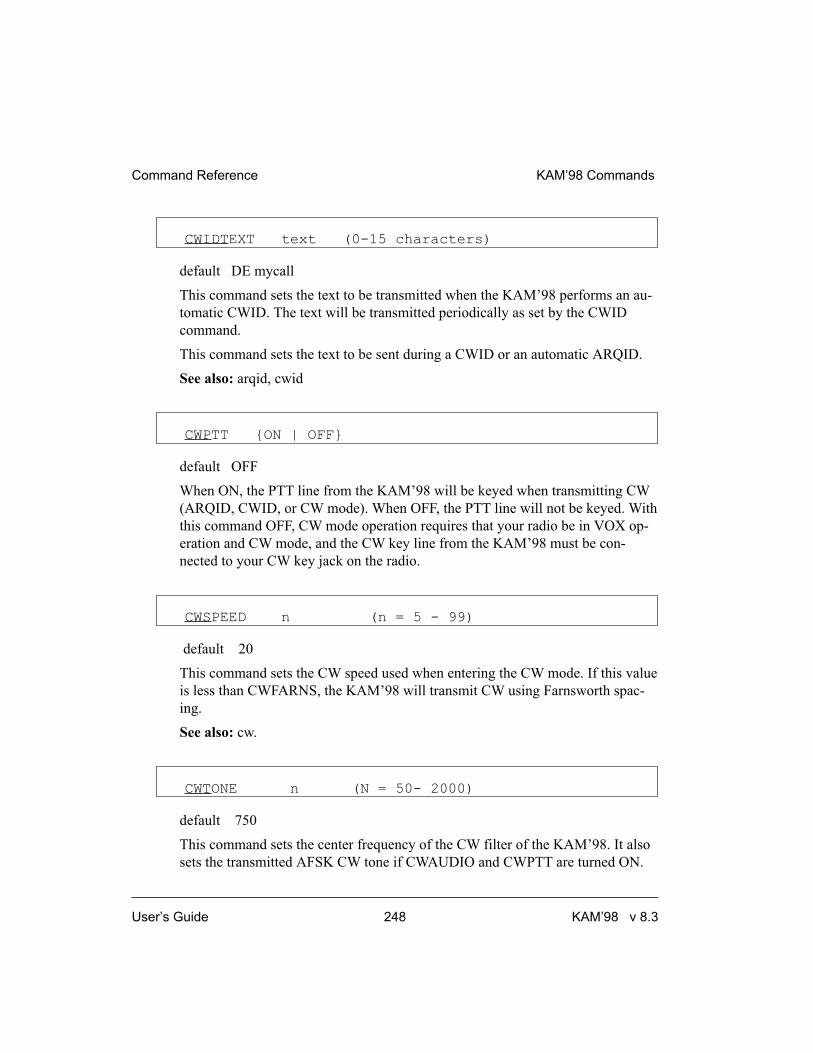
CWIDTEXT text (0-15 characters)
default DE mycall
This command sets the text to be transmitted when the KAM’98 performs an au-
tomatic CWID. The text will be transmitted periodically as set by the CWID
command.
This command sets the text to be sent during a CWID or an automatic ARQID.
See also: arqid, cwid
CWPTT {ON | OFF}
default OFF
When ON, the PTT line from the KAM’98 will be keyed when transmitting CW
(ARQID, CWID, or CW mode). When OFF, the PTT line will not be keyed. With
this command OFF, CW mode operation requires that your radio be in VOX op-
eration and CW mode, and the CW key line from the KAM’98 must be con-
nected to your CW key jack on the radio.
CWSPEED n (n = 5 - 99)
default 20
This command sets the CW speed used when entering the CW mode. If this value
is less than CWFARNS, the KAM’98 will transmit CW using Farnsworth spac-
ing.
See also: cw.
CWTONE n (N = 50- 2000)
default 750
This command sets the center frequency of the CW filter of the KAM’98. It also
sets the transmitted AFSK CW tone if CWAUDIO and CWPTT are turned ON.
Command Reference KAM’98 Commands
User’s Guide 248 KAM’98 v 8.3

+ The default is set to 750 to accommodate the majority of transceivers. If your
transceiver can operate with CWTONE set to 1000, that might be preferable.
CWWEIGHT n (n = 0 - 15)
default 0
This command adds weighting to a transmitted CW signal. Normally a dash is
three times the length of a dot. If weighting is used, the dash will be n * 0.1 times
longer than normal. For instance, if n is set to 7, then a dash would be 7 * 0.1 (or
0.7) times longer than normal, making the dash 3.7 times the length of the dot.
DAMA {ON | OFF}
default OFF
When ON the TNC can operate as a DAMA slave station once connection is es-
tablished with a DAMA master station. When OFF the TNC operates in standard
Packet mode (i.e., CSMA — Carrier Sense Multiple Access).
See also: damachck
DAMACHCK n (n = 0 to 255)
default 18
This command sets a DAMA timeout timer in 10-second increments. If the TNC
is connected to a DAMA master station (that is, operating in DAMA slave mode)
and the master does not poll the TNC for data before the DAMACHCK timer ex-
pires, the TNC will revert to CSMA operation and disconnect from the DAMA
master.
This command was added to allow the user to regain CSMA connect capability in
the event the DAMA master fails to poll because of a node failure - lightning
strike, power outage, etc.
See also: dama
KAM’98 Commands Command Reference
KAM’98 v 8.3 249 User’s Guide

DAYSTR text (see format below)
default mm/dd/yyyy hh:mm:ss
The DAYSTR command is used to set the FORMAT of your date/time display.
DO NOT enter an actual date or time, simply enter the form of the display you
would like, using the lower case letters m, d, h, y, and s as described below.
The format you enter is used for all time stamps, including the PBBS, KA-Node,
Mheard list, etc.
The lower case characters m, d, y, h, and s have special meaning to this command
and will be replaced with data from the software clock. The lower case m will be
replaced with the minutes the first time it appears after a lower case h. If h, m, y,
d, or s is specified as a single character, the corresponding date/time element will
be displayed as a single digit if the value is less than 10. Entering two characters
will force a two digit display for values under 10. If the month is entered as three
ms, it will be displayed as the first three characters of the month name (JUL).
You may also enter any other text you wish, allowing you to add such things as
your time zone.
Entering “yyyy” controls the output of the DAYTIME command as follows: If
the two byte year (yy) is equal to 80 through 99, “yyyy” in DAYSTRING will
produce an output from 1980 through 1999; if the two byte year (yy) is equal to
00 through 79, the output will be from 2000 through 2079.
+ Remember ALL lower case m, d, y, h, and s will be replaced by actual values.
Some examples of setting the DAYSTR command and the resulting time/date
display are:
DAYSTR setting Displayed Date/Time
mm/dd/yy hh:mm:ss 07/16/93 12:14:22
d.m.y h:mm:ss 16.7.93 12:14:22
d.mm.yy h:mm 16.07.93 12:14
mmm d 19yy h:mm CST JUL 7 1993 12:14 CST
TIME hh:mm DATE: mmm dd, yyyy TIME 12:14 DATE JUL 07, 1993
Command Reference KAM’98 Commands
User’s Guide 250 KAM’98 v 8.3

+ This command is used to define how date and time are to be displayed; it is not
used to enter an actual date and time (which you do by using DAYTIME). If you
enter an actual date and time with the DAYSTR command, your clock will ap-
pear to stop.
See also: daytime
� DAYTIME yymmddhhmm[ss]
DAYTIME is used to enter a date and time (after which time and date are format-
ted for display by the specifications given in DAYSTR).
When date and time are entered, using the input format specified in the command
and explained below, the values entered are used to set the software clock/calen-
dar. The software clock/calendar is then used for MHEARD and NDHEARD log-
ging, as well as for CSTAMP and MSTAMP functions.
When entering the daytime digits, enter them in pure number sequence with no
spaces, dashes, or slashes. Notice that there are two digits each for entering a
year, month, day, hour, minute, and (optionally) second. Also, notice that you
need to use the order given here, which has nothing to do with the format (given
in DATSTR) for displaying date and time values. For example, to enter 1986,
January 2, at 22:30:00 hours, the value of the DAYTIME parameter would be
860102223000. In this case, seconds were entered, so the string is 12 characters
long (2 characters for each of six pieces of information entered).
If DAYTIME is entered with no parameter, the daytime is displayed using the
format defined by the DAYSTR command.
+ Hint: If the time appears to be stuck, check the current value of DAYSTR, to be
sure that the DAYSTR setting is being used to format the display of time and
date, and not (in error) to attempt to supply an actual date and time. If this is not
the case, fix the problem and see if time and date displays work correctly.
See also: cstamp, daytweak, daystr, mheard, mstamp
KAM’98 Commands Command Reference
KAM’98 v 8.3 251 User’s Guide

DAYTWEAK n (n = 0 - 15)
default 8
This parameter is used to adjust the software clock, if needed, for accurate time
keeping. Increasing the parameter will slow the clock, decreasing the parameter
will speed up the clock. Each count corresponds to .43 seconds increase or de-
crease per 24 hours. Ambient temperature will affect the clock to some degree.
DAYTWEAK has no effect on the battery-backed clock (BBC); that clock is set
only by using the DAYTIME command. The software clock stops when a soft reset
or powering off occurs, and upon power on the software clock is set to the value of
the BBC, if installed.
See also: wefax
DBLDISC {ON | OFF}
default OFF
When OFF, only one disconnect command (D) need be given to terminate an un-
successful connect attempt. If you are actually connected, the normal disconnect
sequence will occur.
When ON, a normal disconnect sequence will always occur (you will not be dis-
connected until you receive an acknowledge of your disconnect or until the retry
count is exceeded). A second D is required to force a local disconnect independ-
ent of the retry counter.
See also: disconnect
� DELETE n (n = $00 - $FF)
default $08 <Ctrl+H>
Command Reference KAM’98 Commands
User’s Guide 252 KAM’98 v 8.3

This command sets the character to be used as the delete character. When this
character is typed, the last input character is deleted. The most common settings
are $08 (backspace) and $7F (delete).
See also: bkondel
DIDDLE {ON | OFF}
default ON
When ON, a diddle character is sent when no characters are available from the
keyboard or buffer during transmission in RTTY or ASCII mode. In RTTY, the
diddle character is the LTRS character; in ASCII, the diddle character is a null.
When OFF, a constant MARK frequency is transmitted.
DIGIPEAT {ON | UIONLY | OFF}
default ON
When ON, any packet received that has MYCALL, MYALIAS, or MYNODE
(if KA-Node is active) in the digipeat list of its address field will be
retransmitted. Each station included in the digipeat list relays the packet in the or-
der specified in the address field. Digipeating takes place concurrently with other
TNC operations and does not interfere with normal connected operation of the
station. To disable digipeat operations (via MYCALL, MYALIAS, or MYNODE)
turn this command OFF.
If UIONLY is selected, the TNC will digipeat UI frames only (DIGIPEAT affects
only MYCALL, MYNODE, and MYALIAS).
See also: hid, myalias, mycall, mynode
� DISCONNE [MYPBBS | MYREMOTE | MYNODE x ]
(x=KA-Node)
immediate
KAM’98 Commands Command Reference
KAM’98 v 8.3 253 User’s Guide

When given without options, “disconnect” will initiate an immediate disconnect
request on the current I/O stream. A successful disconnect results in the display
of “*** DISCONNECTED”. If the RETRY count is exceeded while waiting for
the connected station to acknowledge, the TNC moves to the disconnected state
on that stream. Entering a second Disconnect command before RETRY has ex-
pired will result in an immediate disconnect on your end, but may leave the other
station thinking it is still connected to you. Disconnect messages are not dis-
played when the TNC is in Transparent Mode. Other commands may be entered
while the disconnect is in progress.
DISCONNE MYPBBS
Issue this command if you want to cause the personal mailbox to issue a discon-
nect to the user of the mailbox. D MYPBBS is what you should type, do not type
the call entered in the mypbbs command.
DISCONNE MYNODE x (x = KA-Node circuit)
x may be any of the KA-Node circuits in use, designated by A, B, C, etc. This
command will cause the node to disconnect the stations linked through the node
on the circuit specified. MYNODE does not refer to the call entered in the
mynode command, but is the actual characters to type.
DISCONNE MYREMOTE
Issue this command if you want to cause a disconnect to someone connecting to
your TNC via MYREMOTE. Also, issue this command if you with to discon-
nect from the prompt of a MYREMOTE station you’ve connected to.
See also: dbldisc, newmode, retry, status
� DISPLAY [c]
immediate
This command causes the TNC to display a list of all the parameters in the TNC.
You may also display only a selected group of parameters by specifying the ap-
propriate class identifier for that group. When using the DISPLAY command
with a subclass be sure to use a space between the DISPLAY command and the
subclass. Subclasses of related parameters are:
Command Reference KAM’98 Commands
User’s Guide 254 KAM’98 v 8.3

ASYNC asynchronous port parameters
(TNC to computer)
AMTOR parameters affecting AMTOR (ARQ and
FEC) and NAVTEX/AMTEX modes
ASCII parameters affecting ASCII mode
CHAR special TNC characters
CW parameters affecting CW mode
GPS parameters related to GPS operations
GT parameters affecting G-TOR mode
ID ID parameters
LINK parameters affecting packet link
(TNC to TNC)
MONITOR monitor parameters
PBBS mailbox commands
PT parameters affecting Pactor mode
RTTY parameters affecting RTTY mode
TIMING timing parameters
XTRA some transmission related parameters,
such as FSKINV
Individual parameter values can be displayed by entering DISPLAY and the com-
mand name, followed by “CR”.
See also: Display Listings section
� DWAIT n (n = 0 - 255)
default 0
DWAIT defines a delay to be used to avoid collisions with digipeated packets.
The value entered for “n” is the number of 10 ms intervals, after last hearing data
on the channel, for the KAM’98 to wait before it begins its own key-up sequence.
This value should be established and agreed on by all members of a local area
network. The best value will be determined by experimentation but will be a
function of the key-up time (TXDELAY). This feature is made available to help
alleviate the drastic reduction of throughput which occurs on a channel when
KAM’98 Commands Command Reference
KAM’98 v 8.3 255 User’s Guide

digipeated packets suffer collisions. Digipeated packets are not retried by the
digipeater but must be restarted by the originating station. If all stations specify
DWAIT, and the right value is chosen, the digipeater will capture the frequency
every time it has data to send since digipeated packets are sent without this delay.
Observations have proven that a better algorithm for avoiding collisions between
end-user stations, while still allowing digipeaters the high-priority access they re-
quire is achieved using Persistence and Slottime to determine proper transmit in-
tervals, and setting DWAIT to 0.
See also: persist, slottime
� ECHO {ON | OFF}
default ON
When ON, characters received from the computer by the TNC are echoed back
and displayed. If you are receiving double print of characters entered at the key-
board, turn this command OFF. This corresponds to the setting in your terminal
program for duplex. If your program is set for full-duplex set ECHO ON. If your
program is set for half-duplex (some call it echo) then set ECHO in the TNC to
OFF. Regardless of the setting of this command, the TNC will not echo an
X-OFF or X-ON character to the terminal when it receives a STOP or START
character. Echo is disabled in Transparent Mode.
See also: bkondel, flow
ESCAPE {ON | OFF}
default OFF
This command specifies the character which will be sent to the terminal when an
escape character ($1B) is received in a packet. When OFF, $1B is sent. This is
useful if your terminal interprets ESC characters as screen positioning commands
(ANSI). When ON, the escape character is sent as a dollar sign ($).
Command Reference KAM’98 Commands
User’s Guide 256 KAM’98 v 8.3
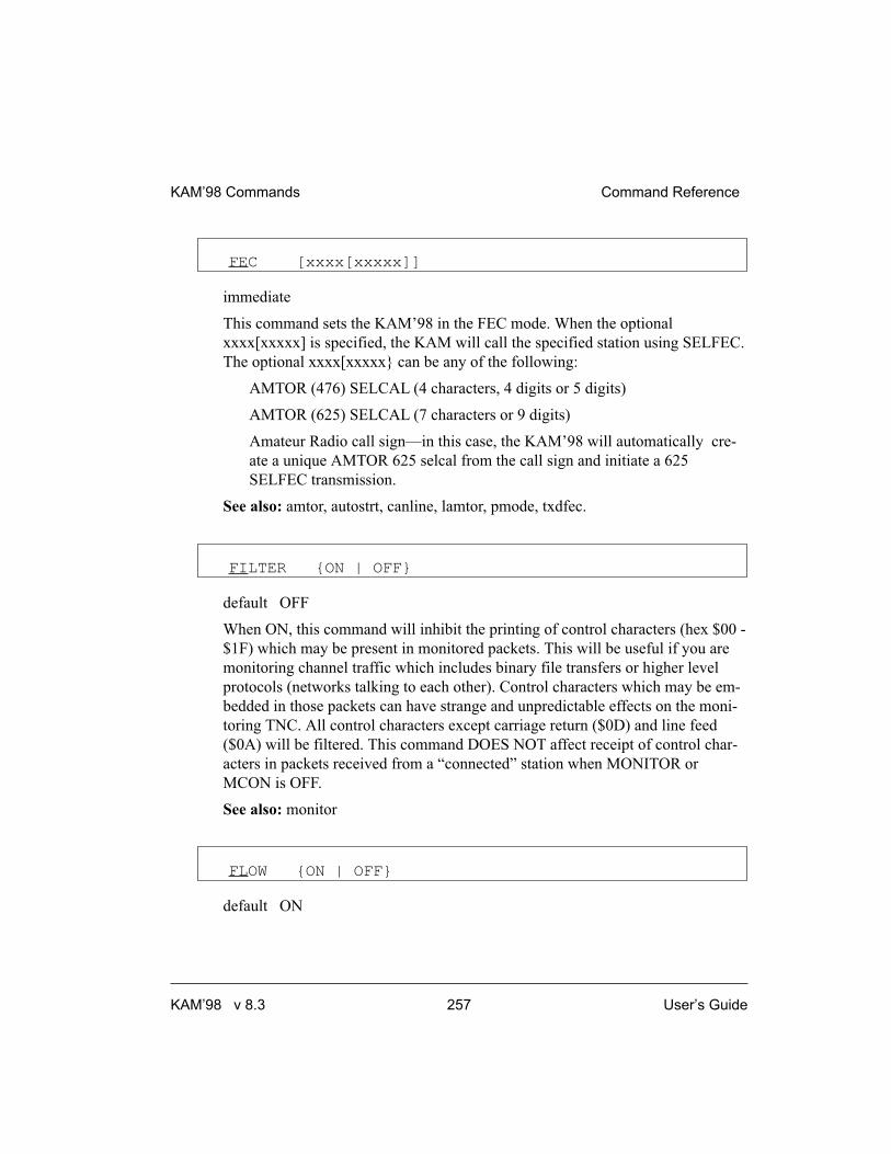
FEC [xxxx[xxxxx]]
immediate
This command sets the KAM’98 in the FEC mode. When the optional
xxxx[xxxxx] is specified, the KAM will call the specified station using SELFEC.
The optional xxxx[xxxxx} can be any of the following:
AMTOR (476) SELCAL (4 characters, 4 digits or 5 digits)
AMTOR (625) SELCAL (7 characters or 9 digits)
Amateur Radio call sign—in this case, the KAM’98 will automatically cre-
ate a unique AMTOR 625 selcal from the call sign and initiate a 625
SELFEC transmission.
See also: amtor, autostrt, canline, lamtor, pmode, txdfec.
FILTER {ON | OFF}
default OFF
When ON, this command will inhibit the printing of control characters (hex $00 -
$1F) which may be present in monitored packets. This will be useful if you are
monitoring channel traffic which includes binary file transfers or higher level
protocols (networks talking to each other). Control characters which may be em-
bedded in those packets can have strange and unpredictable effects on the moni-
toring TNC. All control characters except carriage return ($0D) and line feed
($0A) will be filtered. This command DOES NOT affect receipt of control char-
acters in packets received from a “connected” station when MONITOR or
MCON is OFF.
See also: monitor
FLOW {ON | OFF}
default ON
KAM’98 Commands Command Reference
KAM’98 v 8.3 257 User’s Guide

When FLOW is ON, any character entered from the terminal will halt output to
the terminal until the current packet or command is completed (by SENDPAC,
PACLEN, or PACTIME). Canceling the current input to the TNC or typing the
REDISPLAY-line character will also cause output to resume. FLOW will keep
the display of received data from interfering with data entry.
When FLOW is OFF, received data will be “inter-leaved” with keyboard entry. If
using a split screen terminal program, you should have FLOW OFF and ECHO
OFF to allow received data to be displayed while you type into the TNC’s
type-ahead buffer.
See also: canline, canpac, cpactime, echo, paclen, redisplay, sendpac
FRACK n (n = 1 - 15)
default 4
Each increment specifies 1 second intervals. After transmitting a packet requiring
acknowledgment, the TNC waits FRACK seconds before incrementing the retry
counter and sending the packet again. If the retry count (specified by the RETRY
command) is exceeded, the current operation is aborted. If the packet address in-
cludes digipeaters, the time between retries is adjusted to FRACK * ((2 * m) + 1)
where m is the number of digipeater stations specified. When the retried packet is
sent, a random wait time is also added to avoid lockups where two units repeat-
edly collide with each other.
The FRACK timer begins when PTT is released (the packet has been sent) and is
suspended when data carrier from the radio is present, or when your station is
transmitting.
See also: connect, resptime, retry
FSKINV {ON | OFF}
default OFF
Command Reference KAM’98 Commands
User’s Guide 258 KAM’98 v 8.3

This command controls the polarity of the FSK output on the Radio port of the
KAM’98. When OFF, MARK is open-collector and SPACE is ground. When
ON, the polarity of MARK and SPACE is reversed.
FREEQUAL n (n = 0 - 31)
default 20
FREEQUAL sets the maximum number of bits in error allowed when scanning
for free signals. This is used to detect commercial short stations free signal trans-
missions in SITOR.
When more than n errors are detected, nothing is output. When less than or equal
to n errors are detected, “FREESIG ...” prints.
+ For more detail, see HF E-Mail in the non-packet “modes of operation” section.
FULLDUP {ON | OFF | LOOPBACK}
default OFF
When OFF (i.e., half duplex), the data carrier detect signal is used as a packet
collision avoidance signal. When ON, the modem is run full duplex, and carrier
detect does not inhibit transmission. The full duplex mode may be useful espe-
cially for satellite operations using duplex radio setups. Full duplex should not be
used unless both you and the station you are communicating with have full du-
plex capability. LOOPBACK is the same as full duplex (i.e., FULLDUP ON) as
far as protocol is concerned, but the receive circuit is still active; this allows you
to connect a simple wire between the transmit and receive pins on the radio con-
nector to verify operation of the modem circuitry. This same function can also be
realized with printed circuit board jumper J5
GMON
immediate
KAM’98 Commands Command Reference
KAM’98 v 8.3 259 User’s Guide

The GMON command places the KAM’98 in the monitor mode, allowing you to
monitor G-TOR QSOs. To exit the GMON Mode and return to the command
prompt, type <Ctrl+C> X.
GPSHEAD n string (n = 1-4) (string up to 8 chars)
default 1 $GPGGA ( string 2, 3, and 4 = <blank>)
This command determines which GPS NMEA sentences will be stored in the LT
buffers. n (1-4) determines which buffer will be used to store the data, and string
is a NMEA sentence header.
When the header is received from the GPS unit, the KAM’98 will store up to 128
characters in the associated LT buffer.
+ To clear one of the four strings, enter the buffer number, n (n = 1-4), and nothing
else, then press the ENTER key.
See also: blt, lt, ltp, ltrack
GPSINIT string (string up to 128 characters)
default (blank)
This command establishes a string which will be sent to the attached GPS unit
upon power-up (i.e., initial text sent to terminal in GPS Mode). This may be use-
ful to configure your GPS unit to provide only the information you require. Some
GPS units may require more than one sentence; consult your GPS unit manual.
To send more than one, enter a <Ctrl+N> at the end of each sentence, and the
KAM’98 will send a CR/LF sequence to the GPS unit. A single % will clear the
string.
To send a string to the AUX serial port (pin 4), configure the GPS port. The
“string” specified by GPSINIT will then be sent to the GPSPORT on any reset.
See also: gpshead, gpsport, intface
Command Reference KAM’98 Commands
User’s Guide 260 KAM’98 v 8.3

GPSPORT [baud] [NORMAL|INVERTED] [CHECKSUM|NOCHECK]
default 0 NORMAL CHECKSUM
This command provides a second input serial port for a GPS unit, using a firm-
ware UART.
If ‘baud’ is non-zero, pin 3 of the AUX port can be used as a GPS input during
regular operation of the KAM’98. In this case, jumper J9 must be in position 2.
Also, if jumper J3 is set to posts 1-2, AUX pin 4 provides an output based on the
GPSINIT command. This may be used to send an initialization signal to an at-
tached GPS device.
‘Baud’ may be set to 0, 300, 600, 1200, 2400, or 4800.
NOTE: If the INTFACE command is set to GPS, the KAM’98 assumes that the
GPS devices is attached to the normal RS-232 port and not the secondary AUX se-
rial input. If INTFACE is set to KISS, XKISS, or GPS, you should set GPSPORT to
zero.
If NORMAL is specified, the sense (polarity) of pin 3 is RS-232; the pin would
be expecting RS-232 input or 0-5v input of the same polarity. If INVERTED is
specified, the pin would be expecting polarity opposite of RS-232. Most
standalone GPS units use RS232 or 0-5v output of the same polarity.
If CHECKSUM is specified, the firmware will pass along only GPS sentences
which have valid checksums. The NOCHECK parameter will pass along all GPS
sentences which have valid checksums and also GPS sentences which do not
have a checksum.
+ Not all GPS units will append checksums to the GPS sentences that they
send; some GPS sentences require a checksum while others do not.
If you wish to use the GPSPORT, note that the KAM’98 cannot send any initial-
ization string to the GPS unit; you must pre-initialize the GPS unit before con-
necting it up to the XCD pin.
See also: gpsinit
KAM’98 Commands Command Reference
KAM’98 v 8.3 261 User’s Guide

GPSTIME {OFF|VALID|ON} {GGA|GLL|RMC|ZDA }
default VALID RMC
This command specifies how the KAM’98 clock will be set from a GPS device.
If GPSTIME is set to OFF, the KAM’98 software clock is not set when NMEA
strings are received. If GPSTIME is set to VALID, the clock is set, if and only if
the valid bit in the string specified is set.
If GPSTIME is set to ON, the time is acquired from the string specified.
Note: In any event, any string must have a valid checksum. Second, time is not up-
dated if the time received in a string is the same as the last time received. Third,
GGA and GLL strings do not include a date; the ZDA string does not include a
“valid bit:” and some units do not include a valid bit with the GLL string.
GTDOWN n (n = 2 - 30)
default 6
Sets the number of consecutive bad frames received before switching to the next
lower baud rate (G-TOR baud rates supported are 300, 200 and 100).
GTERRS n (n = 30 - 255)
default 40
Sets the time-out attempts for G-TOR. When attempting to link with another sta-
tion, the unit times out after n attempts without a response. When already linked,
reception of n consecutive faulty frames results in a timeout.
GTFUZZY n (n = 0 - 3)
default 3
Sets the number of bits in a data acknowledgement that may be corrupted.
Command Reference KAM’98 Commands
User’s Guide 262 KAM’98 v 8.3

GTOR [xxxxxxxxxx]
immediate
Entering G-TOR with no parameters will place the KAM’98 in G-TOR Standby,
allowing you to respond to an incoming link request or transmit a CQ or other
broadcast. If you also have MONITOR ON, you can monitor FEC broadcasts. By
using the optional callsign parameter, this command will initiate a link attempt
with station xxxxxxxxxx. You can discontinue the link attempt, or break an exist-
ing link, with the <Ctrl+C>D directive, which will lave you in the G-TOR
Standby mode, or with the <Ctrl+C>X directive, which returns you to Packet
Mode (cmd: prompt).
NOTE: If ARQBBS is on, you cannot transmit FEC and you will not be able to
monitor FEC.
See also: arqid, cwid.
GTTRIES n (n = 0 - 9)
default 2
Sets the maximum number of attempt to speed up. If unsuccessful after n at-
tempts, the KAM’98 will return to its previous G-TOR speed until it receives
GTUP consecutive good frames.
GTUP n (n = 2 - 30)
default 3
Sets the number of consecutive good frames received before switching up to 200
or 300 baud operation.
KAM’98 Commands Command Reference
KAM’98 v 8.3 263 User’s Guide

HBAUD n (n = 50 - 1200)
default 300
This baud rate specifies the rate of data exchange when operating in packet
mode. The value of HBAUD has NO relationship to the terminal baud rate speci-
fied with ABAUD. In order to communicate with other packet stations, the baud
rate must be the same at each end of the link. As a general rule, 300 baud is used
on frequencies below 28 MHz, 1200 baud is used on frequencies above 28 MHz.
FCC rules currently limit the maximum baud rate to 300 when operating below
28 MHz.
Note: When switching from 300 baud packet operation on HF to 1200 baud packet
operation on VHF/UHF, remember to change the following (HF defaulted) parame-
ters: Mark, Space, SWP, Slottime, Persist, Maxframe, Paclen, Hbaud. See the
packet section in the modes of operation chapter for further detail (page 144).
HEADERLN {ON | OFF}
default ON
When ON a carriage return is output to the terminal between the header and text
of monitored packets. This causes the packet header and time stamp (if on) to be
displayed on one line, with the packet text displayed below it on the next line.
When receiving packets addressed only to you (MONITOR and/or MCON OFF)
this parameter does not apply. When OFF the data will be on the same line as the
header.
See also: cstamp, mcon, monitor, mstamp
� HELP [command]
immediate
Entering the word “HELP” alone, without any argument, will generate a display
listing all commands available in the KAM’98.
Command Reference KAM’98 Commands
User’s Guide 264 KAM’98 v 8.3

When the name of a command is entered also (e.g., HELP CONVERS), a brief
description of that command will be displayed. A wild card also can be used;
entering “Help C*” will display brief descriptions of all commands beginning
with C.
HELP can also be called by entering “?”.
HID {ON | OFF}
default ON
When ON, an ID packet will be sent every 9.5 minutes, provided that packets are
being digipeated through your station, or routed through your KA-Node, or into
your PBBS. This command should be ON if digipeating, KA-Node or pbbs is en-
abled. If OFF, periodic identification packets will not be sent.
See also: digipeat, id, myalias, mynode, mypbbs, numnodes, pbbs
HTEXT text
default blank
The HTEXT command is used by your PBBS to provide hierarchical routing in-
formation. Use this command to enter the hierarchical portion of your packet ad-
dress. Do not enter your callsign or the first period of your packet address.
A hierarchical address consists of your state, country, and continent codes, sepa-
rated by periods. Some areas (in large states particularly) use sub-state designa-
tors. For instance, a station in Rhode Island might use a hierarchical address of
RI.USA.NOAM. This means Rhode Island (RI) which is in the United States
(USA) which is in North America (NOAM). In this case, you should set the
HTEXT to RI.USA.NOAM
If you are unsure of your hierarchical address, contact your local packet BBS
sysop and ask what the proper addressing is for your location. Entering “%” will
clear any text previously entered.
Note: Your PBBS will not forward or reverse forward unless HTEXT is set.
KAM’98 Commands Command Reference
KAM’98 v 8.3 265 User’s Guide

ID
immediate
When this command is entered an identification packet will be transmitted. This
command may be used to insure that your station identification is the last trans-
mission before taking the station off the air.
The ID packet is an unnumbered information <UI> packet whose data consists of
your station identification as set in MYCALL and a listing of other modes, if you
have activated them.
The MYCALL will be appended with “/R” if DIGIPEAT is ON, MYALIAS
callsign appended with “/D”, MYNODE callsign appended with “/N”, and
MYPBBS callsign appended with “/B”.
This packet will be addressed to “ID” and digipeated via any addresses specified
in the UNPROTO command.
See also: hid, unproto
� INTFACE {TERMINAL|NEWUSER|BBS|GPS|HOST|KISS|XKISS}
default NEWUSER
When set to NEWUSER, the TNC will operate with a standard terminal or com-
puter running a terminal emulation program with a limited command set avail-
able. When set to TERMINAL, the full command set of the TNC is available.
When set to BBS, the TNC deletes certain messages (i.e. *** connect request,
*** FRMR, etc) for greater compatibility with full-service BBS programs such as
WØRLI, WA7MBL, CBBS, etc. When INTFACE is set to KISS mode of opera-
tion, users interact with the TNC using software that implements the KISS code
specified by Phil Karn (for more information, see the KISS Operation section of
this manual). When INTFACE is set to XKISS mode of operation, users interact
with the G8BPQ extended KISS protocol (for more information, see the KISS
Operation section of this manual). When INTFACE is set to HOST, the TNC will
talk to the attached computer using the Kantronics HOST mode and users com-
municate with the TNC using “host mode” software (for more information, see
the HOST Operation section of this manual).
Command Reference KAM’98 Commands
User’s Guide 266 KAM’98 v 8.3

When INTFACE is set to GPS, the KAM’98 will enter GPS mode upon power
up. Data from the serial port will be parsed according to the GPSHEAD com-
mand, text will be placed into the LT buffers, and beacons will be transmitted ac-
cording to the setting of the BLT commands.
To have the KAM’98 exit GPS Mode, connect a PC or terminal to it and issue
three <Ctrl+C> characters (see COMMAND for details).
For instructions on exiting KISS, XKISS, and HOSTmodes, see the appropriate
sections of the “modes of operation” chapter of this manual.
NOTE: After changing the setting of this command to KISS, XKISS, HOST, or
GPS, a soft reset is required for the new mode to take effect (see RESET
for details).
INVERT {ON | OFF}
default OFF
When ON, signals received in RTTY, ASCII, or AMTOR, and signals transmitted
using AFSK, are inverted. While in RTTY, ASCII, or AMTOR mode, entering a
<Ctrl+C>I directive will toggle the inversion ON and OFF.
� K
immediate
This single letter command is synonymous with CONVERS. It is included as a
single-keystroke convenience for entering Convers Mode.
See also: convers
KNTIMER n (n = 0 - 255)
default 15
KAM’98 Commands Command Reference
KAM’98 v 8.3 267 User’s Guide

If there is no activity (data) on a KA-Node circuit for n minutes, the KA-Node
will disconnect both the input and output sides of the KA-Node circuit. Setting
KNTIMER to 0 disables this feature.
See also: rnrtime
LAMTOR
immediate
This command places the KAM’98 in the Listen AMTOR mode. The KAM’98
will receive FEC, SELFEC, or ARQ signals. The KAM’98 will not transmit
when operating in LAMTOR mode.
See also: amtor, fec, misschar.
LCOK {ON | OFF}
default ON
When ON, no character translation occurs in the TNC. If OFF, lower case charac-
ters will be translated to upper case before being output to the terminal from the
TNC. This case translation is disabled in Packet Transparent Mode.
LFADD {ON | OFF}
default OFF
When ON, a line-feed will be appended to every carriage return received from
the keyboard before being transmitted. When OFF, no line feeds will be added to
the transmitted signal.
See also: cradd
Command Reference KAM’98 Commands
User’s Guide 268 KAM’98 v 8.3

LFSUP {ON | OFF}
default OFF
When ON, this command suppresses any line-feed characters received from the
other station, relying on your terminal program to properly advance to the next
line. When OFF, the line-feeds received from the other station are not suppressed
but are sent to your terminal as received.
See also: autolf, crsup
LGETCHAR $xx
default $05 (hex, Ctrl+E)
This command allows the user to specify a Hot Key to perform the same function
as “LT RESTART.”
LGETCHR specifies a hot key that is functional in command or converse mode,
to output the unformatted strings from the LTEXT buffers to the RS-232 port.
+ Programs such as APRS use this character to gather NMEA fix strings via the
RS-232 port.
LLIST [ON | OFF] [NONE | {+|-}callsign |
callsign1,callsign2...]
default OFF NONE
LLIST is used to determine which stations (callsigns) may NOT use your station
for ANY purpose, including digipeating. When LLIST is ON, the TNC will NOT
recognize those packets received with any callsign that appears in the LLIST’s
(lid) list of callsigns. In addition, when LLIST is ON, you will not be able to con-
nect to any station that is on that list.
The maximum number of callsigns allowed in LLIST is 10. Up to 10 callsigns
may be entered at once, using the format shown after the command name, and the
new list of from 1 to 10 callsigns will replace whatever list was there before. The
LLIST command can be used to add a single callsign (+callsign), so long as there
KAM’98 Commands Command Reference
KAM’98 v 8.3 269 User’s Guide

is room for the new callsign on the list (if there is not, the TNC responds with
“EH?” and returns you to the command prompt). Similarly, you can remove a
single callsign (-callsign) from the list. And to remove all items from the current
list, enter LLIST NONE.
A callsign entered without a SSID will match any SSID of that callsign. To match
a specific SSID only, enter the callsign with that SSID: for example, callsign-n,
where n = 0-15.
LT {n [text] | RESTART } (n = 1-4) (text up to
128 chars)
immediate
This command is used with GPS activity. Entering n “text” fills the specified LO-
CATION Text (LT) buffer with “text”. n specifies which buffer to use (1-4). If
GPSHEAD is set for this buffer, and if the INTFACE command is set to GPS, the
buffer contents will be updated automatically by the GPS data.
To clear one of the 4 LT strings, enter “LT n%”, where “n” is the number of the
LT string you want to clear.
Entering RESTART causes the LT buffers to be output in an unformatted manner
via the RS-232 port, and the BLT timers are restarted. “Unformatted” means that
only non-empty LT strings are output and that there is no proceeding number in-
dicating which strings are output.
Note: When switching from 300 baud packet operation on HF to 1200 baud packet
operation on VHF/UHF, remember to change the following (HF defaulted) parame-
ters: Mark, Space, SWP, slottime, Persist, Maxframe, Paclen, Hbaud. See the
packet section in the modes of operation chapter for further detail (page 144).
See also: blt, gpshead, ltp, ltrack
Command Reference KAM’98 Commands
User’s Guide 270 KAM’98 v 8.3

LTP n dest [via call1[,call2,...]] (n =1-4)
default GPS (for n = 1-4)
This command sets the destination callsign and the digipeaters used to transmit
the LT strings. n specifies which string (1-4). The destination callsign defaults to
GPS; however, you may want to change it to APRS, LOCATE, POSIT, or some
other destination. Up to 8 digipeater callsigns may be specified.
See also: lt
LTRACK n [LT1] [LT2] [LT3] [LT4] [SYSOP] [TIME]
default 0
This command allocates memory for a special tracking buffer used to store LT
messages. n defines the amount of memory (Kbytes) set aside for the LT mes-
sages (limited by available RAM). Specifying the LT1 through LT4 parameters
determines which messages will be stored in the tracking buffer. If SYSOP is
specified, only a user with SYSOP privileges may access the tracking buffer, and
if TIME is specified, a time stamp will be included, in front of the LT message.
Specified LTs are put in the LTRACK buffer based on the BLT settings.
The LTRACK buffer is accessed by connecting to the mailbox (MYPBBS) and
using the mailbox’s List Tracking buffer Command (LTR). To see the syntax of
this command, type HELP at the BBS prompt.
To change LTRACK, you need to enter the entire command name, LTRACK, not just
the short form (LTR).
See also: ltp, blt, GPS operation section
MALL {ON | OFF}
default ON
KAM’98 Commands Command Reference
KAM’98 v 8.3 271 User’s Guide

When ON, monitored packets include connected and unconnected packets be-
tween other stations. If OFF, only other station’s unconnected packets (UI
frames) will not be displayed.
This is a useful arrangement when stations are talking as a group in an uncon-
nected configuration.
See also: monitor
MARK n (n = 50 - 4000)
default 2125
This command sets the mark frequency. The MARK command must be set less
than the SPACE command.
For 1200 baud (VHF) packet operation, set MARK to 1200.
Note: When switching from 300 baud packet operation on HF to 1200 baud packet
operation on VHF/UHF, remember to change the following (HF defaulted) parame-
ters: Mark, Space, SWP, Slottime, Persist, Maxframe, Paclen, Hbaud. See the
packet section in the modes of operation chapter for further detail (page 144).
+ Note: The TNC spedifications are for MARK values from 50 through 2400.
Higher values (to 4000) are for experimental use.
See also: shift, space.
MAXFRAME n (n = 1 - 7)
default 1
MAXFRAME sets an upper limit on the number of unacknowledged information
packets which can be outstanding at any one time. The TNC will send
MAXFRAME number of packets in a single transmission, if they are available.
Note: When switching from 300 baud packet operation on HF to 1200 baud packet
operation on VHF/UHF, remember to change the following (HF defaulted) parame-
Command Reference KAM’98 Commands
User’s Guide 272 KAM’98 v 8.3

ters: Mark, Space, SWP, Slottime, Persist, Maxframe, Paclen, Hbaud. See the
packet section in the modes of operation chapter for further detail (page 144).
See also: paclen
MAXUSERS n (n = 1 - 26)
default 10
This command causes the TNC to allocate the memory required for the maxi-
mum number of simultaneous connections you wish to allow. Each connection
uses a different stream. In order to direct what you want to say to a different
stream you use the STREAMSW character. All streams may be used for outgoing
packets, but USERS sets the number that may be used for incoming connections.
Changing the value of MAXUSERS will cause the TNC to perform a “soft re-
set”. Note that you may not change the value of MAXUSERS while you are con-
nected, since this would reset the TNC and cause all existing connections to be
lost.
Note: Although you must spell out the entire command word (MAXUSERS) to
change the current value of MAXUSERS, you can enter the short form,MAXU, if
you just want to see the current value of MAXUSERS.
See also: status, streamsw, users
MBEACON {ON | OFF}
default ON
This command determines whether packets addressed to Beacon or ID will be
displayed on the screen.
If you do not wish to display Beacon or ID packets, turn this command OFF.
See also: beacon, id, monitor
KAM’98 Commands Command Reference
KAM’98 v 8.3 273 User’s Guide

MCOM {ON | OFF}
default ON
Supervisory (control) packets are not monitored unless MCOM is set ON and
MON is ON. In addition if your station is connected, control packets are not
monitored unless MCON is also ON. Control packets, when displayed, are distin-
guished from information packets by the “<>” and “<<>>” character sets ap-
pended to the packet header. With these characters, a letter is included to denote
the type of control packet received, e.g. <<c>> - a connect request packet. The
types of control packets are listed below.
<C> Connect request
<D> Disconnect request
<DM> Disconnected Mode
<UA> Unnumbered Acknowledge
In addition, the following bracketed information will be added to the Information
packets as appropriate:
<UI> Unconnected Information frame
<Is> Information frame (connected);
s = send sequence number
See also: ax25l2v2, monitor, mresp
For details on control packets, see the book AX.25 Amateur Packet-Radio
Link-Layer Protocol Version 2.0 October 1984, available from the ARRL.
MCON {ON | OFF}
default OFF
When OFF, and connected, the TNC will display only those packets addressed to
you. Any header information displayed will be determined by the settings of
STREAMEV and STREAMCA. When OFF, and not connected, all eligible pack-
ets (as determined by other monitor commands) will be displayed. When ON, all
eligible packets will be displayed, whether connected or unconnected.
See also: monitor, streamca, streamev
Command Reference KAM’98 Commands
User’s Guide 274 KAM’98 v 8.3

MHEARD [SHORT | LONG | CLEAR]
immediate
This command causes display of a list of stations heard. An asterisk, *, indicates
that the station was heard through a digipeater. The date/time the station was last
heard is also displayed.
If the S option is used, i.e. MHEARD S, then only the callsigns of the stations
heard will be displayed.
If the L option is selected, all callsigns contained in the received packet including
the digipeater paths, are displayed. For example:
NØGZZ > ID 10/16/88 14:31:30
VIA TOP,KCI,WØXI
Here, your station heard NØGZZ transmitting an ID packet. NØGZZ was also
using the digipeating path TOP, KCI, WØXI. If your station heard NØGZZ via
one of these other stations, an asterisk would show by the call or alias of the last
digipeater heard. When listed short, the asterisk would show beside NØGZZ.
+ Whenever PASSALL is ON, packets will not be checked for errors and no addi-
tions will be made to the MHEARD list.
If the C option is used, the list is cleared.
See also: daytime, passall
MHEADER {ON | OFF}
default ON
When ON, the headers are displayed for all monitored packets.
When OFF, headers are not displayed and only data is output to the terminal.
Since only I and UI frames have data, only these frames are displayed.
+ To avoid confusion when MHEADER is OFF, use BUDLIST to restrict the moni-
tored data.
See also: monitor,mcon,mbeacon,mall,suplist,budlist
KAM’98 Commands Command Reference
KAM’98 v 8.3 275 User’s Guide
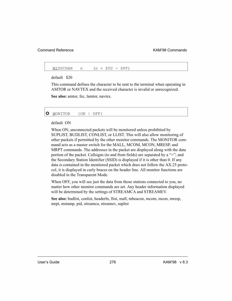
MISSCHAR n (n = $00 - $FF)
default $20
This command defines the character to be sent to the terminal when operating in
AMTOR or NAVTEX and the received character is invalid or unrecognized.
See also: amtor, fec, lamtor, navtex.
� MONITOR {ON | OFF}
default ON
When ON, unconnected packets will be monitored unless prohibited by
SUPLIST, BUDLIST, CONLIST, or LLIST. This will also allow monitoring of
other packets if permitted by the other monitor commands. The MONITOR com-
mand acts as a master switch for the MALL, MCOM, MCON, MRESP, and
MRPT commands. The addresses in the packet are displayed along with the data
portion of the packet. Callsigns (to and from fields) are separated by a “>”; and
the Secondary Station Identifier (SSID) is displayed if it is other than 0. If any
data is contained in the monitored packet which does not follow the AX.25 proto-
col, it is displayed in curly braces on the header line. All monitor functions are
disabled in the Transparent Mode.
When OFF, you will see just the data from those stations connected to you, no
matter how other monitor commands are set. Any header information displayed
will be determined by the settings of STREAMCA and STREAMEV.
See also: budlist, conlist, headerln, llist, mall, mbeacon, mcom, mcon, mresp,
mrpt, mstamp, pid, streamca, streamev, suplist
Command Reference KAM’98 Commands
User’s Guide 276 KAM’98 v 8.3

MORSE code TX RX
Where: “code” is entered as a combination of * and - characters, “TX” represents
a keyboard character entered in hex or decimal, and “RX” denotes the charac-
ter(s) displayed upon reception (entered in hex, decimal, or two alpha characters).
This command is used to define the desired keyboard character and display char-
acter(s) represented for each code listed in the table below. Only those codes
listed may be defined using the MORSE command; standard Morse codes may
not be redefined.
If you try to define a previously defined code, you will get the message “TX
CHARACTER ALREADY DEFINED.” In order to delete an entry, use the com-
mand MORSE 0 0 to clear the code, then redefine it. Refer to the ASCII chart at
the end of this manual for a listing of hex codes.
Codes available for definition by the MORSE command are:
MORSE
CODE TX RX CODE TX RX
**— $00 $00 *-*- $2A(*) $4141(AA)
—-* $00 $00 —— $00 $00
***-* $21(!) $534E(SN) **-** $00 $00
**-*- $00 $00 **—* $00 $00
*-*** $25(%) $4153(AS) *-**- $00 $00
*-*-* $2B(+) $4152(AR) *-*— $00 $00
*—** $00 $00 *—*- $00 $00
*—-* $00 $00 -**-* $2F(/) $2F(/)
-**— $00 $00 -*-** $00 $00
-*-*- $26(&) $4B41(KA) -*—* $28(() $28(()
-*-— $00 $00 —**- $00 $00
—*-* $00 $00 — *— $00 $00
—-*- $00 $00 ***-*- $23(#) $534B(SK)
*-***- $00 $00
See also: cw, prosign.
KAM’98 Commands Command Reference
KAM’98 v 8.3 277 User’s Guide

MRESP {ON | OFF}
default ON
When ON, monitored packets include the following AX.25 response packets, if
MONITOR and MCOM are ON. If connected, MCON must also be on. The
bracketed information will appear at the end of the header information. The “<”
and “<<” characters are used to bracket and denote packets received as version 1
or version 2, respectively. For example, “<<RR1>>” denotes a version 2 packet.
In addition upper case characters are used to designate commands (polls) and
lower case characters are used to denote responses for RR, REJ, and RNR. For
example, “<<rr1>>” is a response in version 2.
<FRMR> Frame Reject
<REJr> Reject, r = received sequence number
<RNRr> Device busy, r = received sequence
number
<RRr> Receive Ready, r = received sequence
number
In addition, the following bracketed information will be added to the Information
packets as appropriate:
<Isr> Information frame (connected);
s = send sequence number,
r = received sequence number
See also: ax25l2v2, mcom, monitor
For more information, see the book AX.25 Amateur Packet-Radio Link-Layer
Protocol Version 2.0 October 1984, which may be obtained from the ARRL.
MRPT {ON | OFF}
default ON
This command affects the way monitored packets are displayed. If ON, the entire
digipeat list is displayed for monitored packets, and the station that relayed the
packet is indicated with an asterisk. The MONITOR command must be ON for
this command to work, and if connected MCON must also be ON. If OFF, only
Command Reference KAM’98 Commands
User’s Guide 278 KAM’98 v 8.3

the originating station and the destination station callsigns are displayed for mon-
itored packets.
See also: monitor
MSTAMP {ON | OFF}
default OFF
This command enables time stamping of monitored packets. The date and time
information is then available for use for automatic logging of packet activity or
other computer applications. The date and time are set initially by the DAYTIME
command, and the date format is determined by the DAYSTR command. The
MONITOR command must be ON for this command to work, and if connected
MCON must also be ON.
See also: cstamp, daytime, monitor
MXMIT {ON | OFF}
default ON
When ON, the KAM’98 will display transmitted packets as monitored data on
your terminal. Repeated packets will be displayed as they are sent over the radio.
The frames to be displayed will be controlled by the MONITOR, MCOM,
MCON, and MRESP commands, and will obey the settings of TRACE,
MSTAMP, HEADERLN, 8BITCONV and FILTER commands.
See also: monitor
MYALIAS xxxxxx-n (n = 0-15)
default disabled
Setting this command to a callsign or character string enables digipeating by us-
ing the MYALIAS. Enter up to six characters (plus optional SSID) which are dif-
ferent than those used for MYCALL, MYNODE, MYPBBS, or MYREMOTE.
KAM’98 Commands Command Reference
KAM’98 v 8.3 279 User’s Guide

For example: you may enter LAW-3 as the MYALIAS, which would be easier to
remember for stations wishing to digipeat through a station in Lawrence, enroute
to a station more distant. You may disable the alias digipeating with the com-
mand MYALIAS %.
See also: hid
MYAUTOST xxxxxxx
default mycall
This command specifies the callsign used for automatically starting receive oper-
ation in RTTY or ASCII when the AUTOSTART command is ON. The callsign
may be up to seven (7) characters long, allowing for MARS callsigns.
See also: autostrt.
� MYCALL xxxxxx-n (n = 0-15)
This command tells the TNC what its callsign is.
The extension n is called a Secondary Station Identifier (SSID) and is defaulted
as 0, but may be any number from 0 to 15. All packets originated by the TNC
will contain this callsign in the FROM address field. Any packets received by the
TNC with this callsign in the TO address field or digipeat fields will be re-
sponded to appropriately (connect, disconnect, ack, digipeat, etc.).
+ When the TNC is first turned on out of the box, or after a hard reset, it asks you
for your callsign - there is no default. The callsign you enter then for MYCALL
is automatically used to compute other IDs too (MYPBBS, MYNODE, and
CWIDTEXT), adding an SSID for each. Changing MYCALL at the “cmd:”
prompt does not affect MYPBBS, MYNODE, or CWIDTEXT
See also: cwidtext, digipeat, id, myalias, mynode, mypbbs, myremote
Command Reference KAM’98 Commands
User’s Guide 280 KAM’98 v 8.3

MYDGPS call
default blank
This command accommodates differential GPS operation.
In GPS mode only, if a UI packet is received addressed to the call in MYDGPS,
the data from the UI packet is output on the RS-232 port.
MYDROP n (n = 0-15)
default disabled
This command sets the KISS address of the radio port in the KAM’98. A KISS
frame with the upper nibble of the command byte set to this value will address
this KAM’98.
See also: intface, KISS operation section
MYGROUP {cccc | nnnn | nnnnn | cccccccc | nnnnnnnnn |
callsign}
default {based on mycall}
This command is used to set a SELCAL that can be used for reception of
SELFEC transmissions. This allows several stations to use the same group selcal,
and still maintain their own individual selcal. You may set the 4-character group
selcal using 4 characters, 4 numbers, or 5 numbers. To set the 7-character (CCIR
625) group selcal, enter 7 characters, 9 numbers, or an amateur callsign.
See also: autostrt.
MYGTCALL xxxxxxxxxx
default {based on mycall}
This command establishes the callsign used for G-TOR link. Up to 10 printable
ASCII characters/numbers may be entered.
KAM’98 Commands Command Reference
KAM’98 v 8.3 281 User’s Guide
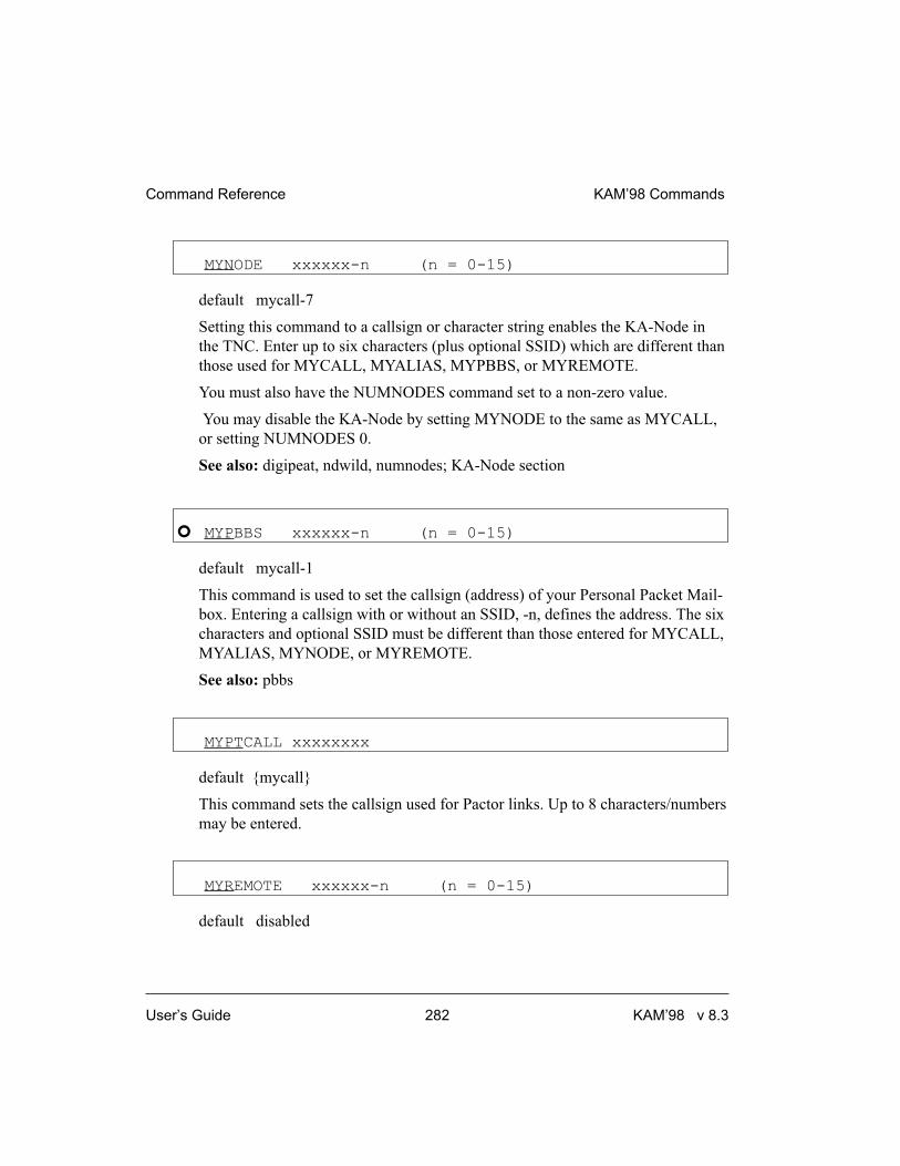
MYNODE xxxxxx-n (n = 0-15)
default mycall-7
Setting this command to a callsign or character string enables the KA-Node in
the TNC. Enter up to six characters (plus optional SSID) which are different than
those used for MYCALL, MYALIAS, MYPBBS, or MYREMOTE.
You must also have the NUMNODES command set to a non-zero value.
You may disable the KA-Node by setting MYNODE to the same as MYCALL,
or setting NUMNODES 0.
See also: digipeat, ndwild, numnodes; KA-Node section
� MYPBBS xxxxxx-n (n = 0-15)
default mycall-1
This command is used to set the callsign (address) of your Personal Packet Mail-
box. Entering a callsign with or without an SSID, -n, defines the address. The six
characters and optional SSID must be different than those entered for MYCALL,
MYALIAS, MYNODE, or MYREMOTE.
See also: pbbs
MYPTCALL xxxxxxxx
default {mycall}
This command sets the callsign used for Pactor links. Up to 8 characters/numbers
may be entered.
MYREMOTE xxxxxx-n (n = 0-15)
default disabled
Command Reference KAM’98 Commands
User’s Guide 282 KAM’98 v 8.3

This command sets the callsign used for remote access of the TNC. Enter up to
six characters (plus optional SSID) which are different than those used for
MYCALL, MYALIAS, MYNODE, or MYPBBS. In addition, the RTEXT must
be programmed with a text string. A station that connects will be sent a series of
numbers that must be decoded according to RTEXT.
See also: rtext; remote access section
MYSELCAL {cccc | nnnn | nnnnn | cccccccc |
nnnnnnnnn | callsign}
default {based on mycall}
The selcal specified by this command will be recognized, when operating in
AMTOR Mode A, as your station identification. The convention used for
AMTOR selcals is to use the first letter and the last three letters of your callsign
as your 4-character selcal. The MYSELCAL will also accept 4 or 5 digit numbers
and generate the corresponding 4-character selcal automatically from these num-
bers.
If you enter 7 characters, 9 numbers, or an amateur radio callsign, this command
will use this as your 7-character selcal for the CCIR 625 form of AMTOR opera-
tion. If you choose to enter your own seven characters, you must remember that
the CCIR 625 recommendation does not allow the use of the letters G, H, J, L, N,
or W. You must use the MYSELCAL command twice to change both the
4-character and the 7-character selcal. The KAM’98 keeps both selcals and will
respond to either one automatically.
See also: amtor, fec.
NAVCLR
immediate
KAM’98 Commands Command Reference
KAM’98 v 8.3 283 User’s Guide

This command clears the list of messages which have been received in the
NAVTEX/AMTEX mode. Any message which has previously been received will
be eligible to be received again.
See also: navtex.
NAVERR n (n = 0 - 10)
default 5
The NAVERR command specifies the maximum percent of errors allowed in a
NAVTEX/AMTEX message before the message is considered invalid. If a mes-
sage is received with less than n% errors, that same message will not be sent to
the terminal if received a second time. If the received message contains excessive
errors, the message “***TOO MANY ERRORS XXXX” will be sent to the ter-
minal and the message will be sent to the terminal if received again.
See also: navtex.
NAVLOG
immediate
This command displays a list of the NAVTEX/AMTEX messages which have
been properly received and therefore are ineligible to be printed if received again.
NAVMSG c[ccc...] | ALL | NONE (c = A - Z)
default ALL
The NAVMSG command specifies which classes of NAVTEX messages will be
sent to the attached terminal. Three classes (A, B, and D) must always be sent ac-
cording to the specification, but may be eliminated by the user. If any of these re-
quired message classes are not selected, the KAM’98 will issue a warning
message. Specifying ALL will set the NAVTEX mode to copy all classes of mes-
sages, and setting NAVMSG NONE will exclude all classes.
Command Reference KAM’98 Commands
User’s Guide 284 KAM’98 v 8.3

Message classes are listed in the NAVTEX section of this manual.
See also: navsta, navtex.
NAVSTA c[ccc...] | ALL | NONE (c = A - Z)
default ALL
The NAVSTA command specifies which originating stations will be copied in the
NAVTEX mode. Each transmitting station uses a unique identifier, allowing you
to select only those stations of interest in your area. If you specify ALL, the
KAM’98 will copy all NAVTEX stations. Specifying NONE will disable copying
of any NAVTEX station, thus effectively disabling the NAVTEX mode, and will
cause a soft reset.
See also: navmsg, navtex.
NAVTEX
immediate
This command will place your KAM’98 in the NAVTEX mode. This allows you
to copy AMTEX messages. (Refer to the NAVTEX section of this manual and
the 8th Computer Networking Conference papers for details.)
See also: misschar, navclr, naverr, navlog, navmsg, navsta, pmode.
NDHEARD [SHORT | LONG | CLEAR]
immediate
This command allows the operator to display a list of nodes whose ID packets
have been heard by the TNC. The list includes KA-Nodes as well as K-Net,
TheNet, NET/ROM and G8BPQ nodes.
K-Net, TheNet, NET/ROM and G8BPQ nodes are identified as:
ALIAS (CALLSIGN)
KAM’98 Commands Command Reference
KAM’98 v 8.3 285 User’s Guide

and Kantronics KA-Nodes will be identified as:
MYNODE (MYCALL)
An asterisk"*" indicates that the station was heard through a digipeater. The
date/time the station was last heard is also displayed. If the S option is used, i.e.
NDHEARD S, then only the callsigns of the stations heard will be displayed.
If the L option is selected, all callsigns contained in the received packet are dis-
played (see MHEARD for display format). If the C option is used, the list of
nodes is cleared.
See also: mynode
NDWILD {ON | OFF}
default OFF
When OFF, the KA-Node will only recognize connect requests directed to the
MYNODE call. When ON, connect requests to any SSID of the MYNODE call
will be recognized as connects to the KA-Node, if that SSID is not being used for
any other ID in the TNC.
See also: myalias, mycall, mynode, mypbbs, myremote
NEWMODE {ON | OFF}
default ON
When ON, the TNC will return to Command Mode if the station on the current
I/O stream disconnects. The TNC will not return to Command Mode if the station
disconnecting is on a different stream. When OFF, a disconnect will not cause the
TNC to change modes.
See also: connect, disconnect, status
NOMODE {ON | OFF}
default OFF
Command Reference KAM’98 Commands
User’s Guide 286 KAM’98 v 8.3

When OFF and a connection takes place, the TNC will change to whatever mode
is specified in CONMODE. When ON, the TNC stays in Command Mode after
connecting to another station; that is, it does not immediately change to Convers
or Transparent Mode.
See also: conmode, connect
NTEXT text (up to 128 characters)
default (blank)
This entry specifies customized text to be sent with the initial KA-Node sign-on
message (when a remote station connects to a KA-Node). Enter any combination
of characters and spaces up to a maximum length of 128. Entering a single “%”
will clear NTEXT.
See also: mynode, numnodes
NUMNODES n (n = 0-26, depending on available RAM)
default 0
This command is used to set the number of allowable circuits through the
KA-Node. For example, if you wish to allow up to 3 simultaneous circuits
through the node, set NUMNODES 3.
+ Changing the value of NUMNODES will cause a soft reset.
Approximately 4K of RAM is used for each circuit. The amount of RAM avail-
able will depend on how much RAM has been used for the PBBS, MAXUSERS,
and MYREMOTE parameters. If you select n larger than available RAM will al-
low, a “Not enough RAM” message will be returned to you. Generally, set the
amount of RAM required first for your PBBS (personal bulletin board) and then
set the desired number of circuits. For example, if you have 32K RAM (128 K is
standard) and n is set to 5 you can only have a 1K mailbox. In this case, if n is
larger than 5, a ‘message saying “not enough RAM” will be returned to you.
KAM’98 Commands Command Reference
KAM’98 v 8.3 287 User’s Guide

Note: While you need to enter all the letters of the command name to change the
value of NUMNODES, you can enter the short-form, NU, to see the current value
of NUMNODES.
See also: mynode; KA-Node section
PACLEN n (n = 0 - 255)
default 64
This command specifies the maximum length of the data portion of a packet. The
TNC will automatically send a packet when the number of input bytes reaches n.
This value is used in both Convers and Transparent Modes. A value of 0 means
256 bytes.
+ When operating VHF 1200 baud packet, change the HF default value of 64 to
128.
Note: When switching from 300 baud packet operation on HF to 1200 baud packet
operation on VHF/UHF, remember to change the following (HF defaulted) parame-
ters: Mark, Space, SWP, Slottime, Persist, Maxframe, Paclen, Hbaud. See the
packet section in the modes of operation chapter for further detail (page 144).
See also: maxframe
PACTIME [EVERY | AFTER] n (n = 0 - 255)
default After 10
This command is used to pace the formation (and transmission) rate of packets in
Transparent mode or in Convers mode if CPACTIME is ON. In addition, a
PACTIME timer is necessary in transparent mode, since the SENDPAC charac-
ter is ignored and treated as data. The timer is not started until at lease one byte
is entered for a packet; hence, a zero data length packet is never formed and sent.
Command Reference KAM’98 Commands
User’s Guide 288 KAM’98 v 8.3

When AFTER is specified, bytes are packaged (if any available) when input
from the terminal stops for n*100 ms or when PACLEN is reached. When
EVERY is specified, input bytes are packaged (if available) and queued for trans-
mission every n*100 ms or when PACLEN is reached.
See also: cpactime, trans
PACTOR [!][callsign]
immediate
Entering PACTOR with no argument will place the KAM in Pactor Standby
mode, allowing you to respond to an incoming link request, to transmit a CQ or
other broadcast (ARQBBS must be OFF), or monitor FEC and ARQ Pactor sig-
nals (MONITOR must be ON for the HF port). By specifying the optional
callsign parameter, your KAM’98 will initiate a link attempt with that station. If
the optional ! is given, the attempt to link will use the long-path protocol, allow-
ing longer distance communication. You can discontinue the link attempt, or
break an existing link with the <Ctrl+C>D directive, which will leave you in
Pactor Standby mode, or with the <Ctrl+C>X directive, which returns you to
Packet mode (“cmd:” prompt).
To transmit a CQ from this mode, use the <Ctrl+C>T directive to begin transmit-
ting, type your message, then use the <Ctrl+C>E directive to return to Standby
mode after all of your messages have been transmitted.
See also: arqid, cwid.
PASS n (n = $00 - $FF)
default $16 <Ctrl+V>
This command selects the ASCII character used to allow the passage of any char-
acters in Converse Mode.
For example, if you wish to send a COMMAND character (<Ctrl+C>) as part of
the packet, you can do so by preceding it with the PASS character. The command
character will be sent rather than returning the TNC to Command Mode. In
KAM’98 Commands Command Reference
KAM’98 v 8.3 289 User’s Guide

Transparent Mode all characters are passed, there are no special functions except
the one combination to get out of transparent mode. However, see TRFLOW.
PASSALL {ON | OFF}
default OFF
This command enables the attempt to display corrupted packets when PASSALL
is ON. If a packet contains beginning and ending flags, the TNC will attempt to
decode the address field as well as the data field and display the packet as speci-
fied by other commands such as MONITOR. MHEARD and NDHEARD log-
ging are disabled when PASSALL is ON.
+ When PASSALL is OFF, packets will be displayed only if the CRC (error check-
ing) is correct and as specified by other commands such as MONITOR.
� PBBS n (maximum value of n depends on available RAM)
default 90 (if RAM = 128K), or 400 (if RAM = 512K)
Setting n greater than 0 allocates memory and activates the Personal Mailbox in
the TNC. The amount of memory allocated will be n kilobytes, and may be lim-
ited by other functions that require memory (e.g. NUMNODES and
MAXUSERS). Changing the size of the PBBS memory allocation will not affect
the contents of the mailbox (messages will be preserved). If you attempt to set
the PBBS smaller than is required for existing messages you will receive the
message “Messages would be lost” and no change will be made to the mailbox
size. In this case to reduce the size of the mailbox you must first either kill some
of the messages or set PBBS 0 which will delete all messages; then set the new
size. Using the PBBS n command with n equal to the current size will renumber
the messages in the mailbox beginning with message number 1. If n is a different
size, the messages will not be renumbered. This command causes a soft reset if n
is different from its previous value.
Note: To change the value of PBBS you must enter the whole command name
(PBBS), but to see the current value, you only need enter the short-form PB.
Command Reference KAM’98 Commands
User’s Guide 290 KAM’98 v 8.3

See also: cmsg, mypbbs, pbheader, pblo, pbperson, ptext; PBBS section
PBFORWRD [bbscall [VIA call1,call2,...call8] ]
[EVERY | AFTER n]
default NONE EVERY 0
This command will cause your PBBS to attempt to initiate a forward of any eligi-
ble mail to another BBS system periodically. Any message in your PBBS which
contains an @BBS field and is not being HELD (H) or has not previously been
FORWARDED (F) is eligible for forwarding. If the keyword EVERY is used, the
PBBS will attempt to forward once every n hours. If you specify the keyword
AFTER, the PBBS will attempt to forward whenever a user disconnects from the
PBBS, and every n hours after that. Setting the time interval will cause the PBBS
to attempt to forward immediately.
After the PBBS has initiated a forward, it will also request a reverse forward if
PBREVERS is ON. Note that full-service BBS systems must be configured to al-
low your station to reverse forward mail to you.
Note: Your PBBS will not forward or reverse forward unless HTEXT is set.
See also: pbrevers,htext
PBHEADER {ON | OFF}
default ON
When ON the routing headers received from a full service BBS will be stored in
the PBBS mailbox. When OFF, these headers are not stored in the mailbox, al-
lowing messages to require considerably less space. The routing headers are
those lines you normally see in messages beginning with R:. Note that the PBBS
will ignore all lines beginning with R: until it sees the first line that does not have
R: in column one. From that point on, all of the message will be stored, even if a
line begins with an R:.
See also: PBBS section
KAM’98 Commands Command Reference
KAM’98 v 8.3 291 User’s Guide

PBHOLD {ON | OFF}
default ON
When ON, any message received over the radio will automatically be held by
your PBBS for you to review. You may then release the message for forwarding
by editing it and changing the H flag (for example, to edit message number 4: E 4
H). When OFF, messages received over the radio are not held, but may immedi-
ately be forwarded from your PBBS. (Note that any message addressed TO or
@ your MYCALL or MYPBBS call will be held regardless of the setting of
PBHOLD.)
PBKILLFW {ON | OFF}
default ON
When OFF, Private and Traffic messages will not be deleted (killed) from your
PBBS after they have been forwarded, but will be marked with an F flag (for-
warded). When ON, Private and Traffic messages will be deleted from the PBBS
after they have been successfully forwarded.
PBLIST [ON | OFF] [NONE | {+|-}callsign |
callsign1,callsign2...]
default OFF NONE
The front panel of your TNC has a mail-status indicator that blinks when there
is unread mail in your PBBS addressed to your callsign (MYCALL) or to your
MYPBBS. And several PBBS commands (LISTMINE, READMINE, and
KILLMINE) operate on mail addressed to your callsign (MYCALL) or to
your MYPBBS.
PBLIST allows you to add up to ten more callsigns to the set of callsigns
included as “mine” for use with the “mail” indicator and the PBBS commands
(LISTMINE, READMINE, and KILLMINE). The PBLIST command has two
parameters: one for creating, changing, or deleting the list of callsigns on the
Command Reference KAM’98 Commands
User’s Guide 292 KAM’98 v 8.3

PBLIST and the other for turning ON or OFF the use of the callsigns on the cur-
rent PBLIST.
+ SSID’s attached to callsigns are always ignored in the mailbox.
The maximum number of callsigns allowed in PBLIST is 10. Up to 10 callsigns
may be entered at once, using the format shown after the command name, and the
new list of from 1 to 10 callsigns will replace whatever list was there before. The
PBLIST command can be used to add a single callsign (+callsign), so long as
there is room for the new callsign on the list (if there is not, the TNC responds
with “EH?” and returns you to the command prompt). Similarly, you can remove
a single callsign (-callsign) from the list. And to remove all items from the cur-
rent list, enter PBLIST NONE.
When you change PBLIST, the new list of callsigns takes effect immediately for use
with the PBBS commands (LISTMINE, READMINE, and KILLMINE). But the new
list will not be used with the mail-status indicator until after the next disconnect
from the PBBS or the next reset.
When PBLIST is ON, the callsigns on the current PBLIST list are included as
“mine” for use with the “mail” indicator and the PBBS commands (LISTMINE,
READMINE, and KILLMINE). Your callsign (MYCALL) and your MYPBBS
are also included as “mine” when PBLIST is ON.
When PBLIST is OFF, only your callsign (MYCALL) and your MYPBBS are
included as “mine” for use with the “mail” indicator and the PBBS commands
(LISTMINE, READMINE, and KILLMINE).
+ Hint: Some uses of PBLIST to give you additional use of your “mail” indicator
(and the PBBS commands shown above) would be to include on PBLIST:
(1) callsigns of family members who are also hams, (2) old callsigns that people
might still be using for you, and/or (3) callsigns that are common errors in trying
to reach you (e.g., replacing a “zero” with an “0" in your callsign).
PBLO [OLD | NEW] [FIXED | VARIABLE]
default NEW VARIABLE
KAM’98 Commands Command Reference
KAM’98 v 8.3 293 User’s Guide

When set to OLD the PBBS will list messages to the user from oldest to newest
(i.e. ascending numerical order). When set to NEW, the newest message will be
listed first. When the second parameter is set to FIXED, the user cannot change
the listing order. When the second parameter is set to VARIABLE, the user may
change the order in which messages will be listed by using the LO command
within the PBBS.
See also: PBBS section
PBPERSON {ON | OFF}
default OFF
When OFF, the personal mailbox will allow messages to be sent to any callsign.
When ON, only messages addressed to the MYCALL , MYPBBS or PBLIST
callsigns will be accepted over the radio, but a message entered from the terminal
or by the SYSOP may be addressed to anyone.
See also: mycall, mypbbs, pbbs
PBREVERS {ON | OFF}
default OFF
When ON, the KAM’98 PBBS will request a reverse forward from another BBS
after it has finished forwarding any mail to the other BBS. This does not affect
the ability of another BBS to reverse forward from your PBBS, but only affects
the action taken by the KAM’98 after it has initiated a forward (PBFORWRD
command). Note: Your PBBS will not forward or reverse forward unless HTEXT
is set.
See also: pbforwrd
PERSIST n (n = 0 - 255)
default 192
Command Reference KAM’98 Commands
User’s Guide 294 KAM’98 v 8.3

+ We recommend that you change the HF default value of 192 to 63 when operat-
ing VHF 1200 baud packet.
This command, used with SLOTTIME, implements an algorithm for channel ac-
cess to send packets. The algorithm used to determine whether or not to transmit
using the PERSIST/SLOTTIME method has been shown to be considerably more
efficient than the DWAIT method used by most standard AX.25 packet stations.
The result of using the persistence algorithm is increased throughput under most
channel conditions.
The value of “n” is used to determine if a packet will be sent after SLOTTIME
expires. For example, let’s assume a PERSIST setting of 63 and a SLOTTIME
setting of 10. This slottime setting corresponds to 100 milliseconds. When the
TNC detects that the channel is clear and available (no carrier is detected), it
starts a timer (SLOTTIME). When the timer expires (100 ms in our case) the
TNC generates a random number between 0 and 255. If the generated number is
equal to or less than the PERSIST value, the TNC keys up the transmitter and
sends the data packet. With our setting of 63 the odds of this occurring after the
first slottime are 1 in 4. (Actually the probability is PERSIST plus 1 divided by
256.) If the TNC generated random number is greater than PERSIST, the TNC
restarts the timer and waits for the timer to expire again before generating a new
random number. This is repeated until the TNC gains channel access and sends
its packet of information.
Making SLOTTIME smaller will cause the TNC to generate the random number
more frequently, whereas raising the PERSIST value will give a better chance
(improve the odds) of transmitting the data. Through careful choice of these val-
ues, it is possible to improve data throughput while at the same time permitting
shared channel usage by other packet stations. The persistence algorithm has
been added on top of the DWAIT algorithm.
Note: When switching from 300 baud packet operation on HF to 1200 baud packet
operation on VHF/UHF, remember to change the following (HF defaulted) parame-
ters: Mark, Space, SWP, Slottime, Persist, Maxframe, Paclen, Hbaud. See the
packet section in the modes of operation chapter for further detail (page 144).
See also: slottime
KAM’98 Commands Command Reference
KAM’98 v 8.3 295 User’s Guide

PHEARD [CLEAR]
immediate
This command will display a list of the last 10 stations that have connected to
your KAM’98 PBBS. The list will show the callsign of the connecting station
and the last time they connected and disconnected.
To clear the PHEARD list of all current entries, enter PHEARD CLEAR.
See also: passall
PID {ON | OFF}
default OFF
When OFF only those packets with a protocol ID of $F0 (pure AX.25) are dis-
played. When ON all packets are displayed. Some of the information in
non-AX.25 packets (for example: TCP/IP, NET/ROM or TheNet) can cause some
computers to lock up. Net/Rom, TheNet and G8BPQ nodes have a PID of $CF,
TCP/IP uses $CC and $CD, and standard AX.25 is $F0.
PMODE {NONE | ASCII | AMTOR | CW | FEC | GTOR |
RTTY | NAVTEX | PACTOR | CONV | TRANS}
default NONE
The PMODE command controls the mode of communication (if any) your
KAM’98 will be in when it is first powered-up or reset.
When PMODE is set to NONE, the KAM’98 will power up in command mode
(i.e. show the cmd: prompt).
+ Once started, non-packet modes of communication are controlled using directives
(immediate commands issued by Ctrl+command letter), so there is no command
line when in a non-packet mode of communication. Directives for a given
non-packet mode of communication cannot be entered unless that mode of com-
munication is active.
Command Reference KAM’98 Commands
User’s Guide 296 KAM’98 v 8.3

When PMODE is set to the name of any non-packet mode of communication
(e.g., PACTOR), the KAM’98 will initiate the specified mode of communication
upon power-up or reset, without any sign-on message.
NOTE: If set to FEC or NAVTEX, you will not receive any message on your termi-
nal when the unit is powered up. To exit any of these modes, type <Ctrl+C>, then
the letter X.
There are three ways to initiate Packet communication using PMODE: To start
Packet with the command line (cmd:), set PMODE to NONE. To start in
Convers mode of Packet, set PMODE to CONV. To start in Transparent mode of
Packet , set PMODE to TRANS.
+ Exiting Transparent Mode of Packet with three <Ctrl+C>s will put the KAM’98
in Command Mode of Packet communication.
Each Kantronics TNC supports modes of communication appropriate for that de-
vice. PMODE is used with all Kantonics TNCs. Multi-port TNCs have a PORT
command, used along with PMODE to specify how the TNC will be configured
after power-up or a reset. In multi-port TNCs, non-packet modes of communica-
tion are always supported by a single port, so the PORT command is not used
with non-packet modes of communication in these devices. An attempt to set
PMODE for a mode of communication not supported by a given device (or a
given port, on a multi-port device) will result in an error message, so a legal value
can be entered instead.
See also: intface
POSTKEY n (n = 0 - 31)
default 0
This command sets a time delay after the last data has been sent to the radio be-
fore the PTT line is released on the Radio port of the KAM’98. The audio will be
turned off n * 0.10 milliseconds before releasing the PTT line.
See also: prekey.
KAM’98 Commands Command Reference
KAM’98 v 8.3 297 User’s Guide

PREKEY n (n = 0 - 31)
default 0
This command sets a time delay between the assertion of PTT and the beginning
of any audio from the KAM’98 Radio port to the radio. The audio will begin n *
0.10 milliseconds after the PTT line is activated.
See also: postkey.
PROSIGN n (n = $00 - $FF)
default $5C
The PROSIGN command is used to select the character used to introduce a CW
prosign. When the selected character is entered during CW transmission or
within text to be used for CW transmission, it will cause the NEXT TWO charac-
ter codes to be combined. For example, \AS will cause the codes for A and S to
be combined into the “wait” code, or “AS.”
See also: morse.
PTDOWN n (n = 2 - 30)
default 6
Sets the number of consecutive bad frames received before switching to 100 baud
Pactor.
PTERRS n (n = 30 - 255)
default 80
Sets the time-out attempts for Pactor. When attempting to link with another sta-
tion, the KAM’98 will time out after n attempts without response. When already
linked, reception of n consecutive faulty frames results in a timeout.
Command Reference KAM’98 Commands
User’s Guide 298 KAM’98 v 8.3

PTEXT text (up to 128 characters)
default (blank)
This entry specifies the customized text sent with the initial PBBS (personal
mailbox) sign-on message. Enter any combination of characters and spaces up to
a maximum length of 128. Entering a single “%” will clear PTEXT. Don’t use
the “>” character in your PTEXT, as this is reserved by BBS systems for their
prompt.
See also: pbbs
PTFECSPD {100 | 200}
default 100
This command will set the speed to be used for Pactor FEC transmissions. When
set to 100, all FEC transmissions will be at 100 baud, and when set to 200, FEC
transmissions will be at 200 baud.
PTHUFF {ON | OFF}
default OFF
When ON, this command allows Huffman compression of 7-bit data when oper-
ating Pactor. The KAM’98 will automatically detect any 8-bit data and will not
apply compression if any 8-bit data is contained in the frame being transmitted. It
will also not compress unless the compression will result in greater throughput.
When OFF, Huffman compression is disabled.
PTLISTEN
immediate
KAM’98 Commands Command Reference
KAM’98 v 8.3 299 User’s Guide

This command places the KAM’98 in the Pactor Listen mode. This mode will al-
low you to copy FEC or ARQ (linked) Pactor stations, but you cannot transmit
from this mode. Use the <Ctrl+C>X directive to return to the command prompt.
PTRPT n (n = 2 - 5)
default 2
When transmitting an unproto Pactor FEC message (i.e., calling CQ), the infor-
mation will be transmitted n times. This is done to improve the chances of other
stations copying your message since FEC transmissions do not use memory
ARQ.
PTSI {ON | OFF}
default OFF
When OFF, supervisory information exhanged between two Pactor units is not
displayed on the terminal. When ON, supervisory information is displayed.
PTSUM n (n = 0 - 120)
default 5
When linked in Pactor, the KAM’98 will attempt to assemble up to n received
frames to obtain a valid frame. This process is called memory ARQ. When a
frame is received, the KAM’98 checks the CRC-16 checksum and if it is invalid,
that frame is stored in memory. The sending station will then repeat the frame,
and the KAM’98 will check again to see if the frame is completely correct. If not,
it will attempt to assemble a good frame by combining the frames received.
PTTRIES n (n = 0 - 9)
default 2
Command Reference KAM’98 Commands
User’s Guide 300 KAM’98 v 8.3

This command sets the maximum number of attempts to increase a Pactor link to
200 baud. If unsuccessful after n attempts, the KAM’98 will remain at 100 baud
until it receives PTUP consecutive good frames.
PTUP n (n = 2 - 30)
default 3
This command sets the number of consecutive good Pactor frames that must be
received before requesting a switch to 200 baud Pactor.
RBAUD n (n = 20 - 1200)
default 45
This command sets the default baud rate used when entering RTTY mode. It also
sets the baud rate used for RTTY operation if PMODE is RTTY. When operating
in the RTTY mode, typing the <Ctrl+C>0 directive will also switch to the
RBAUD rate.
See also: pmode, rtty.
REDISPLA n (n = $00 - $FF)
default $12 <Ctrl+R>
This command is used to change the REDISPLAY input editing character. The
parameter n is the ASCII code for the character you want to type in order to
REDISPLAY the packet or command currently being entered.
You can type this character to cause the TNC to redisplay the packet you have
begun. When you type the REDISPLAY-packet character, the following things
happen: First, type-in flow control is released (if FLOW was enabled). This dis-
plays any incoming packets that are pending. Then a \ (backslash) character is
displayed, and the packet or command you have begun is redisplayed on the next
line. If you have deleted and retyped any character, only the final form of the
packet will be shown. You are now ready to continue typing. Incoming packets
KAM’98 Commands Command Reference
KAM’98 v 8.3 301 User’s Guide

will continue to be displayed until you type the next character of your current
message.
You can use the REDISPLAY-packet character to see a “clean” copy of your in-
put if you are using a printing terminal (or have BKONDEL OFF) and you have
deleted characters. The REDISPLAYed packet will show the corrected text.
You can also use this character if you are typing a message in Convers Mode and
a packet comes in. You can see the incoming message before you send your
packet, without canceling your input.
See also: bkondel, canline, canpac, flow
RELINK {ON | OFF}
default OFF
When OFF, the TNC operating with AX25L2V2 ON does not attempt to auto-
matically reconnect. When ON, the TNC operating with AX25L2V2 ON will at-
tempt to automatically reconnect after RETRY is exceeded.
The KA-Node and the PBBS will never attempt to reconnect regardless of the
setting of this command. If using AX.25 Level 2 Version 1 (AX25L2V2 OFF)
this command has no effect.
See also: ax25l2v2, retry, tries
REPHASE {ON | OFF}
default ON
When ON and operating Mode A AMTOR, the KAM’98 will automatically at-
tempt to rephase with the other station if repeated errors occur. When OFF, re-
peated errors will cause the KAM’98 to return to AMTOR Standby mode.
� RESET
immediate
Command Reference KAM’98 Commands
User’s Guide 302 KAM’98 v 8.3

This command is used to perform a soft reset. Contents of the mailbox (PBBS)
are kept, and the NDHEARD and MHEARD logs are not cleared. Any existing
connections which are not conpermed will be lost, even though the other station
still indicates a connection to your station. The initial sign-on message will be
displayed.
See also: intface, maxusers, myremote, numnodes, pbbs, restore
RESTORE DEFAULT
immediate
When RESTORE D is given, the KAM’98 will revert to it’s factory default set-
tings, perform it’s AUTOBAUD routine, and erase PBBS memory (deleting all
messages and non-default PBBS parameter settings).
See also: reset
RETRY n (n = 0 - 15)
default 10
This command specifies the number of packet retries. Packets are re-transmitted
n times before an operation is aborted. The time between retries (when no ac-
knowledgment is received) is specified by the command FRACK.
See also: ax25l2v2, frack, relink, tries
RING {ON | OFF}
default ON
When ON, three bell characters ($07) are sent to the terminal with each “***
CONNECTED TO” message (when another station initiates the connect).
KAM’98 Commands Command Reference
KAM’98 v 8.3 303 User’s Guide
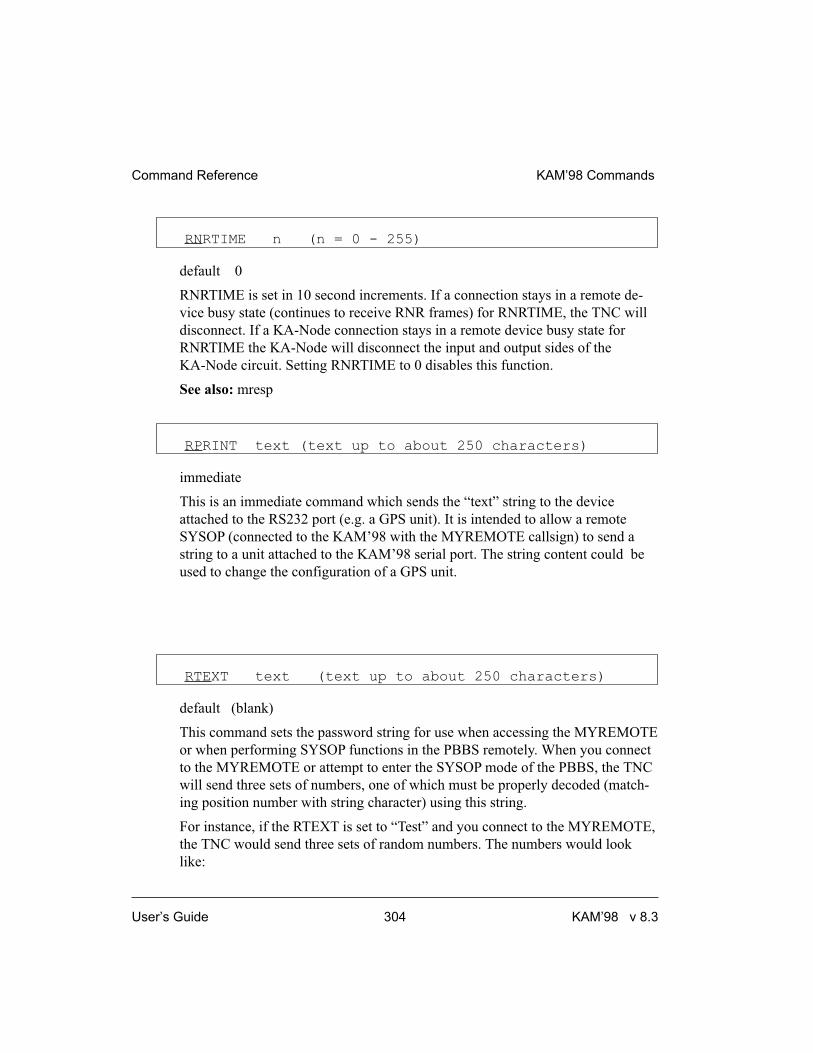
RNRTIME n (n = 0 - 255)
default 0
RNRTIME is set in 10 second increments. If a connection stays in a remote de-
vice busy state (continues to receive RNR frames) for RNRTIME, the TNC will
disconnect. If a KA-Node connection stays in a remote device busy state for
RNRTIME the KA-Node will disconnect the input and output sides of the
KA-Node circuit. Setting RNRTIME to 0 disables this function.
See also: mresp
RPRINT text (text up to about 250 characters)
immediate
This is an immediate command which sends the “text” string to the device
attached to the RS232 port (e.g. a GPS unit). It is intended to allow a remote
SYSOP (connected to the KAM’98 with the MYREMOTE callsign) to send a
string to a unit attached to the KAM’98 serial port. The string content could be
used to change the configuration of a GPS unit.
RTEXT text (text up to about 250 characters)
default (blank)
This command sets the password string for use when accessing the MYREMOTE
or when performing SYSOP functions in the PBBS remotely. When you connect
to the MYREMOTE or attempt to enter the SYSOP mode of the PBBS, the TNC
will send three sets of numbers, one of which must be properly decoded (match-
ing position number with string character) using this string.
For instance, if the RTEXT is set to “Test” and you connect to the MYREMOTE,
the TNC would send three sets of random numbers. The numbers would look
like:
Command Reference KAM’98 Commands
User’s Guide 304 KAM’98 v 8.3

1 2 3 4
1 3 2 4
4 3 1 1
You must then pick ONE of these lines and decode the password string (i.e., as-
sign letters to each letter position). Let’s say you choose to decode line 3
(4 3 1 1). Rewriting the RTEXT string to make this easier we have:
(position) 1 2 3 4
(#) 4 3 1 1
(letter) t s t t
Now, decoding the string, character 4 is “t” character 3 is “s”, character 1 is “ t”
and character 1 is “t”.
You must send the following in response to the string of numbers:
tstt
If correct, you’ll receive the MYREMOTE prompt (“prompt:”).
+ Case is significant and spaces are valid characters.
If you fail to properly decode the password, the remote KAM’98 will send three
new lines of numbers. You will be given a maximum of three attempts to prop-
erly decode the password string. If you fail in three attempts, the TNC will dis-
connect. After failing in three attempts, the MYREMOTE is disabled for 15
minutes.
RTTY n (n = 20 - 1200)
immediate
This command places the KAM’98 in the RTTY mode. The parameter n sets the
transceiver baud rate. If n is not specified, the baud rate specified in RBAUD is
used.
See also: autostrt, canline, pmode, rbaud.
KAM’98 Commands Command Reference
KAM’98 v 8.3 305 User’s Guide
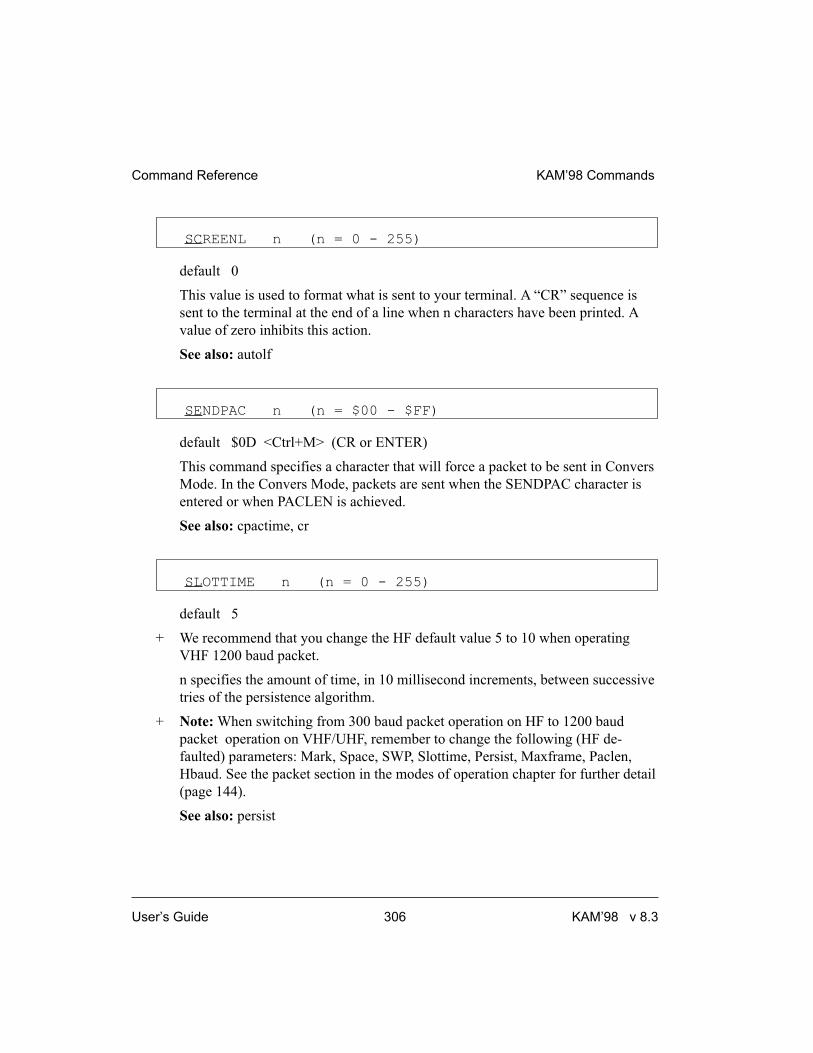
SCREENL n (n = 0 - 255)
default 0
This value is used to format what is sent to your terminal. A “CR” sequence is
sent to the terminal at the end of a line when n characters have been printed. A
value of zero inhibits this action.
See also: autolf
SENDPAC n (n = $00 - $FF)
default $0D <Ctrl+M> (CR or ENTER)
This command specifies a character that will force a packet to be sent in Convers
Mode. In the Convers Mode, packets are sent when the SENDPAC character is
entered or when PACLEN is achieved.
See also: cpactime, cr
SLOTTIME n (n = 0 - 255)
default 5
+ We recommend that you change the HF default value 5 to 10 when operating
VHF 1200 baud packet.
n specifies the amount of time, in 10 millisecond increments, between successive
tries of the persistence algorithm.
+ Note: When switching from 300 baud packet operation on HF to 1200 baud
packet operation on VHF/UHF, remember to change the following (HF de-
faulted) parameters: Mark, Space, SWP, Slottime, Persist, Maxframe, Paclen,
Hbaud. See the packet section in the modes of operation chapter for further detail
(page 144).
See also: persist
Command Reference KAM’98 Commands
User’s Guide 306 KAM’98 v 8.3

SPACE n (n = 50 - 4000)
default 2295
This command sets the space frequency. The SPACE command must be set
greater than the MARK command.
+ For 1200 baud Packet operation, change SPACE to 2100.
Note: When switching from 300 baud packet operation on HF to 1200 baud packet
operation on VHF/UHF, remember to change the following (HF defaulted) parame-
ters: Mark, Space, SWP, Slottime, Persist, Maxframe, Paclen, Hbaud. See the
packet section in the modes of operation chapter for further detail (page 144).
+ Note: The TNC spedifications are for SPACE values from 50 through 2400.
Higher values (to 4000) are for experimental use.
See also: mark, shift.
START n (n = $00 - $FF)
default $11 <Ctrl+Q>
This command specifies the character sent by the computer to the TNC to restart
output from the TNC. If set to $00 only hardware flow control will be used. For
software flow control, set this parameter to the character the computer will send
to restart data flow.
See also: stop, xflow, xoff, xon
� STATUS [LONG]
immediate
Entry of the STATUS command will display the number of bytes available
(i.e., free bytes) in the RS232 input buffer, the current I/O stream ,and any
streams having a connected status.
KAM’98 Commands Command Reference
KAM’98 v 8.3 307 User’s Guide

Entering LONG will cause the TNC to display the status of all streams allowed
by MAXUSERS, PBBS, NUMNODES, and MYREMOTE.
The current KA-NODE input and output (IO) stream is also indicated. A pound
sign (#) indicates that there is unacknowledged data in the buffers for that stream.
The number immediately following the # is the number of bytes outstanding. The
number in parentheses is the number of packets not yet acknowledged.
The following is an example of a display (using STATUS LONG). A, B, C,
through J (i.e., MAXUSERS = 10) indicate the stream. “A” stream is connected
to KEØSM and has 50 bytes in 2 packets that are unacknowledged. The current
stream (IO) is the “B” stream, which is connected to NØKN. KBØNYK is con-
nected on circuit “A” of the KA-Node. All other streams, node circuits, the BBS,
and the remote access are disconnected. Appending “/P” to the callsign indicates
that the connection is permanent (see CONPERM).
cmd:status long
FREE BYTES 1661
A stream - #50(2) CONNECTED to KEØSM
B stream - IO CONNECTED to NØKN/P
C stream - DISCONNECTED
.....
.....
J stream - DISCONNECTED
BBS DISCONNECTED
REM DISCONNECTED
Ain CONNECTED to KBØNYK
Aout DISCONNECTED
Bin DISCONNECTED
Bout DISCONNECTED
See also: conperm, maxusers, myremote, numnodes, pbbs, streamsw
STOP n (n = $00 - $FF)
default $13 <Ctrl+S>
This command specifies the character sent by the computer to the TNC to stop
output from the TNC. If set to $00 only hardware flow control will be used. For
Command Reference KAM’98 Commands
User’s Guide 308 KAM’98 v 8.3

software flow control set this parameter to the character the computer will send
to stop data flow.
See also: start, xflow, xoff, xon
STREAMCA {ON | OFF}
default OFF
When receiving packets addressed only to you (MONITOR OFF and/or MCON
OFF), setting this command ON will enable the display of the callsign of the con-
nected-to station following the stream identifier of the connection (controlled by
STREAMEV). This is especially useful when operating with multiple connec-
tions allowed.
See also: mcon, monitor, streamev
STREAMEV {ON | OFF}
default OFF
When OFF, the stream indicator is displayed only when a change in streams oc-
curs. When ON, the stream indicator will be displayed with every incoming
packet. This command takes effect only when receiving those packets addressed
to you and MCON is OFF.
See also: mcon, monitor, streamca, streamsw
STREAMSW n (n = $00 - $FF)
default $7C (|)
This command selects the character to be used to signify that a new “stream” or
connection channel is being addressed. To change streams you must type this
streamswitch character followed immediately by the stream designator. The
stream designator is an alphabetic character A through Z, or a through z, limited
by the value of MAXUSERS.
KAM’98 Commands Command Reference
KAM’98 v 8.3 309 User’s Guide

+ If STREAMSW is set to the dollar sign ($24) you will need to enter parameter
values in decimal. Alternatively, precede the $ with the PASS character in order
to enter hex numbers.
The character selected can be PASSed in the Convers Mode by using a special
PASS character, and will always be passed as data in the Transparent Mode. If
operating in the Transparent Mode and you wish to change streams, you must
first return to the Command Mode.
See also: maxusers, pass, status
SUPLIST [ON|OFF] [NONE | {+|-}call | call1,call2,..]
where call={callsign | {<|>}callsign |
callsign{>|<>}callsign}
default OFF NONE
SUPLIST is used to determine which received packets will not be displayed, i.e.
suppressed. When OFF or NONE, SUPLIST will not prevent the display of
packets, even if it has callsigns in it’s list.
The maximum number of callsigns allowed in SUPLIST is 10. Up to 10 callsigns
may be entered at once, using the format shown after the command name, and the
new list of from 1 to 10 callsigns will replace whatever list was there before. The
SUPLIST command can be used to add a single callsign (+callsign), so long as
there is room for the new callsign on the list (if there is not, the TNC responds
with “EH?” and returns you to the command prompt). Similarly, you can remove
a single callsign (-callsign) from the list. And to remove all items from the cur-
rent list, enter SUPLIST NONE.
A callsign entered without a SSID will match any SSID of that callsign. To match
a specific SSID only, enter the callsign with that SSID: for example, callsign-n,
where n = 0-15.
Selective display is enabled when one or two callsigns are combined with a “>”
and/or “<” character. For example, entering “>callsign” will disable display of
packets TO that callsign (assuming SUPLIST is ON), entering “<callsign” will
disable display of packets from the callsign, entering “callsign1>callsign2" will
Command Reference KAM’98 Commands
User’s Guide 310 KAM’98 v 8.3

block display of packets from callsign1 to callsign2, and entering
”callsign1<>callsign2" will block display of packets from callsign1 to callsign2
and vice versa.
+ Note that entering call>call or call<>call counts as two of the 10 maximum
allowed callsigns.
See also: monitor
SWP u,d,t (t+u <128)
default 17, 17, 50.
+ We recommend that you change the HF default values of 17,17,50 to 17,17,108
when operating 1200 baud packet.
This command sets the parameters used for software carrier detect. The first
number (u) is used to increment a counter when a valid mark/space or
space/mark transition occurs in the received signal (i.e. transition occurs at the
beginning of a bit time). The second number (d) is a penalty subtracted from the
counter when a transition occurs in the middle of a bit time. The t value is the
threshold value - when the counter total reaches this value, the carrier detect will
be set true.
The values need to be separated by commas as they are entered (as shown). Also
as shown, spaces between values are not necessary — but entering spaces after
the commas is OK.
Once carrier detect is active, the counter must drop to 0 before carrier detect is
again made false.
Note: When switching from 300 baud packet operation on HF to 1200 baud packet
operation on VHF/UHF, remember to change the following (HF defaulted) parame-
ters: Mark, Space, SWP, Slottime, Persist, Maxframe, Paclen, Hbaud. See the
packet section in the modes of operation chapter for further detail (page 144).
See also: cd
KAM’98 Commands Command Reference
KAM’98 v 8.3 311 User’s Guide

TELEMTRY n ( n = 0 - 255)
default 0
A telemetry beacon is sent every n*10 seconds. If n = 0, the beacon is disabled.
The telemetry beacon is a UI frame sent to BEACON. If there is a current
UNPROTO digipeat path, it will be used to transmit the telemetry beacon.
The data in the UI frame is in the form: “T#nnn,an0,an1,an2,an3,an4,bbbbbbbb”,
where:
• “nnn” is a decimal count for the telemetry beacon and is incremented
each time the beacon is sent. When first used, or after the unit is reset,
the beacon counter begins at 001 (T#001). After reaching 999 (T#999),
the counter cycles around to 000 (T#000).
• “an0", ”an1", “an2", ”an3", and “an4" are the decimal readings on the
corresponding analog inputs of the 68HC11F1 (the KAM’98
microprocessor).
+ Hint: See ANALOG command for more information.
• “bbbbbbbb” is the binary reading of the 8 pins on PORT E of the
68HC11F (PORT E is a shared port with the analog inputs), where
“b” = “1" means a Logic High on the pin and ”b" = “0" means a Logic
Low on the pin. The first ”b" in the string of 8 binary digits is the most
significant bit of PORT E and the last “b” is the least significant bit of
PORT E.
+ Hint: For details on the 8 pins on PORT E, see the KAM’98 schematic.
See the “Modes of Operation” section for more information on the use of telem-
etry along with GPS.
Leading zeros are shown for all telemetry readings.
See also: analog
Command Reference KAM’98 Commands
User’s Guide 312 KAM’98 v 8.3

TOR
immediate
This command places the KAM’98 in TOR Standby mode. In this mode, your
KAM’98 will respond to other stations calling you in AMTOR, Pactor, or
G-TOR automatically. In addition, you can monitor or transmit AMTOR FEC.
If INTFACE is set to TERM, when a station links to you the linked message will
indicate which mode is being used.
TRACE {ON | OFF}
default OFF
When ON, frames received in Packet, G-TOR, Pactor, and AMTOR ARQ are
displayed in their entirety, in hexadecimal, including all header information. All
packets which are also eligible for monitoring will be displayed in normal text.
The TRACE function may be toggled on and off when operating AMTOR ARQ,
G-TOR, or Pactor by using the <Ctrl+C><Ctrl+T> directive.
TRANS
immediate
This command causes immediate exit from Command Mode into Transparent
Mode. The current link state is not affected. There are no special editing charac-
ters, all characters are sent out as received. To get out of Transparent, send the
TNC a modem break if BREAK is ON, or see CMDTIME for a special keyboard
sequence.
See also: break, cmdtime, command
KAM’98 Commands Command Reference
KAM’98 v 8.3 313 User’s Guide

TRFLOW {ON | OFF}
default OFF
This command allows the TNC to respond to software flow control from the
computer while in the Transparent Mode. When TRFLOW is OFF, software flow
control is not used in the Transparent Mode. Hardware flow control will be ex-
pected from the computer by the TNC. The computer program needs to use hard-
ware flow control, and the RS-232 cable needs to be wired with CTS and RTS
connected. When ON, software flow control is enabled and the START and
STOP characters are sent by the computer to the TNC to control the flow of data.
When START and STOP are set to $00, hardware flow control must be used. If
not zero, the TNC will respond to the computer’s START and STOP characters,
and remain transparent to other characters from the terminal or computer for flow
control.
When START and STOP are set for software flow control (normally <Ctrl+Q>
and <Ctrl+S>) all characters can be received in Transparent Mode (including the
START and STOP characters) by setting TRFLOW ON and TXFLOW OFF. You
will not, however, be able to send the START and STOP characters, since the
TNC will interpret them as flow control.
See also: trans, txflow, xflow
TRIES [n] (n = 0 - 15)
default 10
The TRIES command will display and optionally set the number of attempts
which have been made to re-send a packet (on the current stream) which failed to
reach its destination. For instance, if RETRY is set to 10, TRIES will show how
many attempts have already been made to pass the data. For example, if TRIES
were to show 8, “TRIES 3” would reset the counter to make the TNC believe that
it had only tried 3 times so far, thus allowing 7 more attempts before the RETRY
limit is exceeded.
See also: retry
Command Reference KAM’98 Commands
User’s Guide 314 KAM’98 v 8.3

� TXDELAY n (n = 0 - 255)
default 30
This command sets the transmitter key-up delay as 10*n ms. This setting estab-
lishes the time delay between the application of push-to-talk and the start of
packet data to the transmitter. Flags (characters to begin packet) are sent during
the delay. This command needs to be set long enough to give your transmitter
time to come to full power before data is sent. If set too short the beginning of the
packet will be chopped off and another station will never be able to decode you.
If set too long, additional flags at the beginning (heard as a repetitive sound)
waste air time. It may be necessary to increase your TXDELAY to allow the re-
ceiving station sufficient time to switch from transmit back to receive to detect
your signal.
TXDFEC n (n = 0 - 25)
default 0
This command sets the number of extra seconds that the KAM’98 will send phas-
ing signals at the beginning of an AMTOR FEC transmission. This allows more
time for a station to tune your FEC transmission and obtain a lock condition be-
fore you actually begin transmitting data.
See also: fec.
TXDTOR n (n = 0 - 15)
default 5
This command establishes the transmit key-up delay used in AMTOR, G-TOR,
and Pactor operation. Each number increment sets a multiple of 10 ms.
TXFLOW {ON | OFF}
default OFF
KAM’98 Commands Command Reference
KAM’98 v 8.3 315 User’s Guide

This command allows the TNC to send software flow control (XON and XOFF)
to stop and restart the flow of data from the computer while in the Transparent
Mode. When TXFLOW is OFF, hardware flow control must be used between the
computer and TNC. RTS and CTS must be connected between the TNC and
computer for hardware flow control. When TXFLOW is ON, software flow con-
trol between the TNC and computer in Transparent Mode will depend on the set-
ting of XFLOW. XFLOW ON enables software flow control, XFLOW OFF
disables it. When software flow control is enabled, the TNC will send the XON
and XOFF characters to the computer to control data flow.
When set for software flow control, all characters can be sent in Transparent
Mode (including the XON and XOFF characters) by setting TXFLOW ON,
XFLOW ON and TRFLOW OFF. You will not, however, be able to receive the
START and STOP characters, since your terminal program should interpret them
as flow control.
See also: trans, trflow, xflow
UIDIGI ON [+|-] call1[,call2[,call3[,call4]]]
default OFF NONE
Up to 4 call signs can be specified for special digipeater duty. If any of the
UIDIGI calls appears in the to-be-digipeated field of a UI packet, and if
MYCALL does not appear in the source field or any of the has-been-digipeated
fields, the UIDIGI call in the to-be-digipeated field will be replaced by
MYCALL with the H bit set and the packet will be digipeated.
See also: dewait, persist, uidwait, unproto
UIDWAIT [ON|OFF]
default OFF
When UIDWAIT is OFF, “special” digipeat packets (those formed by UIDIGI,
UIFLOOD, or UITRACE only) have their usual channel access; there is no wait
DWAIT or slottime added before transmission once the channel is clear. How-
Command Reference KAM’98 Commands
User’s Guide 316 KAM’98 v 8.3

ever, if UIDWAIT is set ON, the packets awaiting to be digipeated will be sub-
ject to the same wait times as not-to-be-digipeated packets awaiting transmission.
+ By subjecting “special” to-be-digipeated packets to a delay determined by
slottime and persist, it is more likely that to-be-digipeated packets of two or more
stations in the same vicinity would not collide. This may be good if one wants to
guarantee that a digipeated packet will “make it out” of its neighborhood but bad
if one wishes to limit the number of times a packet is redigipeated, such as in
APRS applications.
See also: dwait, persist, uidwait
UIFLOOD name, n,[ID|NOID] (name = 5 char max)(n=0-255)
default disabled,30,NOID
When a UI frame is received with a call in the to-be-digipeated field of the form
‘name’x-y where x is a number (1-7) appended to ‘name’ and y is a ssid (1-7),
the ssid is decrement and the UI frame is digipeated without setting the H bit.
When the packet is digipeated, a checksum is formed over the source, destina-
tion, and data fields of the packet. This checksum is kept for n seconds (0-255). If
an incoming UI packet is eligible for digipeating as above, but its checksum
matches one of those being saved, the packet is discarded (not digipeated). The
buffer holds a maximum of 64 checksums. If the optional parameter ID is se-
lected, the MYCALL call sign is inserted in an additional digipeater address field
with its H bit set.
See also: uidwait
UITRACE name, n
default disabled, 30
When a UI frame is received with a call in the to-be-digipeated field of the form
‘name’x-y where x is a number (1-7) appended to ‘name’ and y is a ssid (1-7),
and MYCALL does not appear in the source field or any of the
has-been-digipeated fields, MYCALL with the H bit set is inserted before the
KAM’98 Commands Command Reference
KAM’98 v 8.3 317 User’s Guide

to-be-digipeated field, the ssid of the to-be-digipeated field is decremented, and
the UI frame is digipeated without setting the H bit of the to-be-digipeated field.
The value of n sets a delay time between duplicate digipeats. Use of this “do not
duplicate within n seconds” feature helps control the number of UI frames
digipeated.
+ If the packet should already have 8 digipeater fields, MYCALL is not inserted.
See also: dwait, persist, uidwait
� UNPROTO {call1 [VIA call2,call3..call9] | NONE}
default CQ
call1 = destination address (this is really just a “dummy” address, as no connec-
tion takes place, people often put their name or CQ here)
call2 ... call9 = optional stations to be digipeated through. A maximum of 8
digipeat addresses (callsigns or aliases) can be specified. This is referred to as a
path.
Each callsign may also have an optional Secondary Station Identifier (SSID)
specified as -n, where n = 1 - 15. The digipeat callsigns are specified in the order
in which they are to relay transmitted packets. This command is used to set the
digipeat and destination address fields for packets sent in the unconnected
(unprotocol) mode. Unproto packets do not receive an acknowledgment and are
not retried. They are sent as Unnumbered I-frames <UI>. The digipeater list is
also used for BEACON and ID packets. If UNPROTO is “NONE”, no uncon-
nected packets will be sent except for BEACON and ID. Unconnected packets
sent from other units can be monitored by setting MONITOR ON. If you are con-
nected, you must also set MCON ON.
See also: beacon, id, monitor, mrpt, xmitok
USERS n (n = 0 - 26)
default 1
Command Reference KAM’98 Commands
User’s Guide 318 KAM’98 v 8.3

This command specifies the channels (streams) which may be available to in-
coming connect requests. For example, if USERS = 5 then an incoming connect
request will connect to the lowest channel A - E, if any of these channels are in
the unconnected state. If none of the 5 channels are available (all of them are
connected), a <DM> packet will be sent back to the requesting station and the
message “*** connect request: (call)” will be output to your terminal, if permit-
ted. If USERS is set to 0 no one will be able to connect to you. If USERS is set
higher than MAXUSERS, the extra is ignored and the message “USERS
LIMITED BY MAXUSERS” will be displayed.
See also: intface, maxusers, streamsw
USOS {ON | OFF}
default ON
When ON, an unshift to letters case occurs when a space is received in BAUDOT
RTTY. If CODE is set to LCRTTY, a space will shift to lower case.
� VERSION
immediate
This command causes the KAM’98 to display its current version number along
with the name of the unit.
WEFAX n m (n = 0 - 6000 ) (m = 1, 2 or 4)
immediate
This command permits the reception of Weather Facsimile.
The audio input is sampled n times per second. Each sample becomes one
data-point sent over the serial port to the computer, where it will be used to dis-
play a single pixel on a weather map.
KAM’98 Commands Command Reference
KAM’98 v 8.3 319 User’s Guide

If m = 1 (or 0), a BLACK/WHITE decision is made on each sample. If m is spec-
ified as 2, two bits of data representing 4 grey levels are conveyed to the serial
port for each pixel, and if m is set to 4, 4 bits representing 16 grey levels are con-
veyed to the serial port.
+ To avoid overrunning the serial port, set the serial port’s rate to greater than (n) x
(m) x (1/8) X (10).
A special computer program must be used to display WEFAX maps sent via the
serial port. Superfax II (dos), by Kantronics, displays black/white images only.
Windows programs to also include grey scale are under consideration at this
time. Example: When using Superfax, set WEFAX to 1280 1.
See also: daytweak, WEFAX Reception in Packet Modes of Operations section
WTEXT message (up to 128 characters)
default {DE mycall}
This entry specifies the text to be sent in response to a WRU command while in
AMTOR ARQ mode only. Enter any combination of characters and spaces up to
a maximum length of 128. Entering a single % will clear WTEXT.
To use the WTEXT as an automatic logon for APLINK BBS systems, set the
WTEXT to “DE call/selcal+?” or “QRA call/selcal+?”. Be sure to include the
“+?” as part of the WTEXT.
+ To use the WTEXT as an auto logon for commercial radio telex (e-mail) services
on HF (such as WLO or Globe Wireless), set WTEXT to the “account number”
they provide you. Check with them for the exact form the account number must
take when placed in the WTEXT.
Command Reference KAM’98 Commands
User’s Guide 320 KAM’98 v 8.3

XFLOW {ON | OFF}
default ON
When ON software flow control will be implemented according to the settings of
START, STOP, XON, XOFF. For normal software flow control set XFLOW ON,
START $11, STOP $13, XON $11, XOFF $13. The TNC expects the computer or
terminal to respond to the flow control characters XON and XOFF, and the TNC
responds to the START and STOP characters from the computer. When XFLOW
OFF, the TNC will only use and recognize hardware flow control lines (CTS and
RTS) to start or stop data. The RS-232 cable must be wired appropriately. If the
software flow control characters are set to $00, software flow control is not possi-
ble.
In the Transparent Mode flow control is also determined by the settings of
TRFLOW and TXFLOW.
See also: start, stop, trflow, txflow, xoff, xon
XKCHKSUM {ON | OFF}
default OFF
This command only applies when INTFACE is set to XKISS. The value of
XKCHKSUM controls whether or not the XKISS CHECKSUM mode is active.
See also: xkpolled
XKPOLLED {ON | OFF}
default OFF
This command only applies when INTFACE is set to XKISS. XKPOLLED con-
trols whether or not the XKISS POLLED mode is active.
See also: xkchksum
KAM’98 Commands Command Reference
KAM’98 v 8.3 321 User’s Guide

XMITECHO {ON | OFF}
default OFF
When ON, characters are echoed to the terminal as they are transmitted over the
radio in the non-packet modes. When OFF, echo to the terminal is immediate.
XMITLVL n (n = 0-255)
default 100
This command may be used to set the modem drive level. You may find it more
convenient to use the CAL command in that it allows you to continuously adjust
drive level by holding down the + or - key while in calibrate mode.
The open circuit voltage range set by the XMITLVL command is from approxi-
mately 1 mvpp to 280 mvpp [low drive range] and from approximately 20 mvpp
to 4 vpp [high drive range]. Drive range is set with jumper J8. When driving a
600 ohm load, these voltages will be half the voltages given.
+ The drive level for an SSB HF radio will likely differ from the drive level of an
FM VHF transceiver.
XMITOK {ON | OFF}
default ON
When ON, transmitting functions are enabled. If turned OFF, transmitting is in-
hibited while all other functions of the TNC are unchanged.
XOFF n (n = $00 - $FF)
default $13 <Ctrl+S>
This command selects the character sent by the TNC to the computer to stop in-
put from the computer. If set to $00 hardware flow control must be used. For
Command Reference KAM’98 Commands
User’s Guide 322 KAM’98 v 8.3

software flow control set this parameter to the character the computer expects to
see to stop sending data to the TNC.
See also: xflow, xon
XON n (n = $00 - $FF)
default $11 <Ctrl+Q>
This command selects the character sent by the TNC to the computer to restart
input from that device. If set to $00 hardware flow control must be used. For
software flow control set this parameter to the character the computer expects to
see to restart sending data to the TNC.
See also: xflow, xoff
KAM’98 Commands Command Reference
KAM’98 v 8.3 323 User’s Guide

blank page
Command Reference KAM’98 Commands
User’s Guide 324 KAM’98 v 8.3

Appendix A: Advanced Installation
This appendix gives you additional information on installation and configuration
beyond that given in the chapters on “Installing your KAM’98” and
“Pacterm 2.0”.
Precautions
The KAM’98 is grounded through its connections to your transceiver, computer,
and power supply. Make sure your transceiver is properly grounded and your
computer has equal ground potential. Follow the grounding instructions in your
transceiver manual.
The multi-conductor cable provided with your KAM’98 is shielded. If you use
other cabling, be certain it is shielded. We do not recommend the use of un-
shielded RS-232 ribbon cable in an amateur radio environment.
Lithium batteries can explode or leak if heated, disassembled, recharged, exposed
to fire or high temperature, or inserted incorrectly.
Connecting to the Computer (DB-25)
+ The KAM’98 communicates with the computer using RS-232 signaling. This for-
mat is compatible with PC compatible computers, the Macintosh, dumb termi-
nals, and most other terminal devices. If your computer or terminal uses TTL
levels (such as the Commodore 64), you will need an after-market converter to
supply the RS-232 signals required by the KAM’98.
Caution: Make sure the power to the transceiver, computer, and KAM’98 is OFF
before connecting any cables.
DB-25 Connector
The KAM’98 uses a standard RS-232 serial port with a DB-25 connector, config-
ured as DCE equipment.
KAM’98 v 8.3 325 User’s Guide

Diagram of Pin Numbers on DB-25 Connector
The following diagram shows the pin numbering on DB-25 connectors:
[paste-in DB-25 diagram (see p.94 9612 P]
Cable Wiring
All Kantronics software requires five wires between the computer and the
KAM’98. The pins that must be connected from your KAM’98 to the computer
for these programs are Txd, Rxd, SG, RTS, and CTS. If you are using other soft-
ware, you should refer to that documentation to determine the cable requirements
for proper operation. Some software does not support hardware flow control and
may fail to operate if the RTS and CTS lines are connected.
The KAM’98 serial port connector has 25 pins, which are configured at the fac-
tory as:
Pin KAM’98 Computer Pin Number
Name Pin Number (DB-9) (DB-25)
FG 1 N/A 1
TXD 2 3 2
RXD 3 2 3
RTS 4 7 4
CTS 5 8 5
DSR 6 6 6
SG 7 5 7
DCD 8 1 8
DTR 20 4 20
NOTE: FG (Frame Ground) and SG (Signal Ground) are tied together in the
KAM’98.
Appendix A: Advanced Installation Connecting to the Computer (DB-25)
User’s Guide 326 KAM’98 v 8.3
The purposes of the pins (by name) are as follows:
FG - FRAME GROUND: This pin is attached to the chassis of the equipment as
a safety ground.
TXD - TRANSMIT DATA: This line carries the data from your computer to the
KAM’98.
RXD - RECEIVE DATA: This line carries the data from the KAM’98 to your
computer.
RTS - REQUEST TO SEND: The KAM’98 checks this line to see if it is permit-
ted to send data to your computer. This pin is controlled by your computer soft-
ware program to provide this information to the KAM¹98. This pin is used for
hardware flow control.
CTS - CLEAR TO SEND: The KAM’98 uses this line to signal your computer
when it can no longer accept data from the computer, or to signal that it is again
ready to accept data. This pin is used for hardware flow control.
DSR - DATA SET READY: This line is set high to indicate that the modem is
ON.
DCD - DATA CARRIER DETECT: The KAM’98 uses this pin to signal the sta-
tus of the current I/O stream to your computer. If you are connected to another
packet station on the current I/O stream, this line will have a positive voltage on
it. If you are disconnected, the voltage on this line will be negative.
DTR - DATA TERMINAL READY: Although interconnected via a buffer IC to
the processor, this line is currently ignored.
Optional Wiring
It is possible to re-configure the DB-25 connector to allow some additional func-
tions through this connector.
Applying Power through the DB-25 connector.
If desired, you may apply DC power to the KAM’98 from Pin 25 (EXT-IN) of
the DB-25 connector. To enable this, connect J2 center pin and Pin 1, J1 center
pin and Pin 2.
Connecting to the Computer (DB-25) Appendix A: Advanced Installation
KAM’98 v 8.3 327 User’s Guide

Resetting the KAM’98 through the DB-25 connector.
EXT-IN via pin 25 of the DB-25 connector may be configured to allow you to
perform a soft reset. This is accomplished by connecting J2 center pin and pin 2,
J1 center pin and pin 1. A momentary contact to ground will cause a soft reset.
Hardware handshaking with DSR and DTR.
It is possible that some terminals or computers use the DTR and DSR pins for
hardware handshaking instead of the RTS and CTS pins. When this is the case,
you must connect the DTR terminal output to RTS on the KAM’98, and connect
the DSR terminal input to CTS on the KAM’98.
Software settings
When using a standard terminal program to communicate with the KAM’98, you
must set the serial port configuration in your program for 8 data bits, no parity,
and one stop bit. The baud rates supported by the KAM’98 are 300, 600, 1200,
2400, 4800, 9600, 19200 and 38400. In general you should use the fastest baud
rate your terminal program and hardware supports. The KAM’98 defaults with
ECHO ON, so you should set your terminal program for “full-duplex” operation.
If you are using a baud rate above 9600 baud, we strongly recommend that you
consider installing special high-speed, buffered UARTS in the serial port of your
computer. These UARTS are available through many parts suppliers and will im-
prove the reliability of high-speed communications. You should ask for the
“high-speed buffered UARTS” (part number 16550 or equivalent) when ordering
from your supplier. Most Pentium systems have these already.
Appendix A: Advanced Installation Connecting to the Computer (DB-25)
User’s Guide 328 KAM’98 v 8.3

Connecting to your Radios
The HF/VHF radio connector on the KAM’98 rear panel is a 9-pin DB style con-
nector, with pin layout as shown below:
[diagram of DB-9 pin connector]
Pin Pin
No. name Function
1 TXA Transmit audio (AFSK out)
2 XCD External carrier detect
3 PTT Push-to-Talk
4 A/D-3 Analog-to-digital input 3
5 RXA Receive audio (AFSK in)
6 GND Ground
7 EXT-IN External input for Power/Reset*
8 CTRLB Control line B
9 GND/KEY Ground or CW Key line *
* See the jumper section for details.
+ Note: Also see the Auxiliary Port for additional connections.
Pin 1: Connects to the microphone input of your radio, providing the audio sig-
nal to be transmitted.
Pin 2: When a ground is applied to this pin, the KAM’98 will not transmit pack-
ets. This pin is normally used as an external means of supplying carrier
detect, but can also be used as a “hardware” transmit inhibit.
Pin 3: When the KAM’98 needs to key your transmitter, it will apply a ground to
this pin. This is an open-drain circuit and requires a positive voltage from your
radio (not to exceed 50 volts or 200 mA).
Connecting to your Radios Appendix A: Advanced Installation
KAM’98 v 8.3 329 User’s Guide
Pin 4: This pin is an analog-to-digital input (A/D-3). The AUX Port also pro-
vides this pin, as well as three additional A/D inputs. See the Analog command
for details.
Pin 5: Receive audio from your radio connects to this pin. This normally will
connect to the external speaker jack on your radio, but may connect to the receive
audio pin on your microphone connector (if available).
Pin 6: This pin connects to the ground of your radio mic connector.
Pin 7: This pin is not normally connected in the KAM’98, but may be configured
as an external reset or to supply power to the KAM’98 using jumpers J1 and J2.
See the Jumper section for details.
Pin 8: This pin is the CONTROL B output from the KAM’98 which may be used
as a control line to your radio or other devices. It is an open-drain circuit, and
will apply a ground on this pin when controlled by the CTRL command in your
KAM’98 (not to exceed 50 volts or 200 mA).
Pin 9: This pin is connected to ground as shipped from the factory. You may
re-configure this pin to perform an external soft reset by using jumpers J1 and
J2. Alternatively, this pin may be used for key out CW if configured with jumper
pin 2 and center pin. See the Jumper section for details.
Appendix A: Advanced Installation Connecting to your Radios
User’s Guide 330 KAM’98 v 8.3

Connecting Devices to the Auxiliary (AUX) Port
The AUX port connector on the KAM’98 rear panel is a DB-9 style connector,
with pin assignments as shown in the table below.
Pin Pin
No. name Function
1 A/D-0 analog-to-digital input 0
2 A/D-1 analog-to-digital input 1
3 A/D-2 analog-to-digital input 2
4 A/D-3 analog-to-digital input 3
5 PWR power
6 GND ground
7 CTRLA control line output A
8 CTRLB control line output B
9 reset soft reset line
Pin 1: This pin is analog-to-digital (A/D) converter input 0. Range is 0 - +5
VDC. See the Analog command for details.
Pin 2: A/D input 1.
Pin 3: A/D input 2.
Pin 4: A/D input 3.
Pin 5: Power may be applied to this pin. See also jumper J2 to enable power.
Pin 6: This is the ground pin.
Pin 7: This pin is control output A; and may be used to as a control line to your
radio or other devices. It is an open drain circuit, and will apply a ground to the
pin. Don’t exceed + 50 V @ 200 ma.
Pin 8: This pin is control output B.
Pin 9: Grounding this pin will cause a soft reset.
Connecting to your Radios Appendix A: Advanced Installation
KAM’98 v 8.3 331 User’s Guide

Interfacing Hand-Held Radios
+ This section is for those who need more information than that given in the “In-
stallation” chapter.
Many transceivers, especially most hand-held models, obtain Push-To-Talk key-
ing by completing a circuit between the mic input and PTT ground. A direct PTT
input to the mic input line of units with this type electret condenser microphone
is not usable without some type of isolation.
If you plan to operate a hand-held transceiver with the KAM’98, you will have to
add a capacitor and resistor to your radio cable.
While you will need to check the exact requirements of your hand-held radio, the
following guidelines may be useful:
• A .1 uF capacitor (non-polarized) usually is required in the transmit
audio line from the TNC to any handheld transceiver (HT) radio. Even if
a capacitor is not required for connection to a particular radio, it can still
be installed, and the transmit audio (packets) will pass through to the
radio.
• ICOM HT radios key the PTT by providing a low impedance path from
the mic input to ground. To accomplish this, simply install a resistor
(approximately 3.9K seems to be a good value) in series with the PTT
wire from the KAM’98, and connect this to the mic input along with the
AFSK line.
+ The ICOM 2A style wiring is most common, and can be used with some
Alinco, Azden, and Standard HTs.
• YAESU radios are similar but use a mono plug and a different value
resistor.
+ The wiring for Yaesu HTs can also be used with Radio Shack HTs.
• Most KENWOOD HT radios key the PTT line by connecting the sleeve
of the mic connector to the sleeve of the earpiece connector. This means
that you will not need a resistor in the PTT wire from the KAM’98,
simply connect the PTT wire to the sleeve of the mic connector. Another
point to watch – most of the KENWOOD HTs (2600 and later) use a
Appendix A: Advanced Installation Connecting to your Radios
User’s Guide 332 KAM’98 v 8.3

three pin mic connector. The AFSK from the KAM’98 should therefore
connect to the RING and not the TIP of the mic connector.
Optional Connections to DB-9 Radio Port
As noted above, Pin 7 can be used either for external (soft) reset or for power in-
put and Pin 9 can be used either for keying or for ground.
Applying Power through the DB-9 connector.
To power the KAM’98 from Pin 7 of the DB-9 connector, you must connect J1
center pin and pin 1, J2 center pin and pin 1.
Resetting the KAM’98 through the DB-9 connector.
To perform a soft reset from Pin 7 of the DB-9 connector, you must connect J1
center pin and pin 1, J2 center pin and pin 2. Momentarily applying a ground to
pin 7 will then perform a soft reset.
Alternatively, pin 9 can be used for either ground or keying CW: Connect J4 cen-
ter pin and pin 1 for ground, center pin and pin 2 for keyout.
Connecting to your Radios Appendix A: Advanced Installation
KAM’98 v 8.3 333 User’s Guide

Appendix B: Advanced Information
Assembly and Disassembly
Should you require access to the KAM’98 to reposition jumpers or for other pur-
poses, disassemble as follows:
1. Turn off power to your KAM’98 and remove all cables from the unit.
2. Using a small Phillips screwdriver, remove the four (4) case screws located
on each side of the case.
3. Remove the top cover from the unit.
NOTE: In most cases, no further disassembly of the unit is necessary. Only if
you need to change a wire jumper or solder connections to the PC board should
you continue with disassembly of the KAM’98.
4. Remove the two (2) screws securing the rear panel to the case.
5. Observe proper static protection precautions and gently lift the rear panel and
the PC board backward and up from the case.
To reassemble, reverse the above procedure.
Hard Reset
The hard reset process is provided to re-initialize the KAM’98 to its default val-
ues. This process may become necessary should operational problems be encoun-
tered or when upgrading your firmware to a new version. The readout specified
in step 5 below will be legible only if your terminal baud rate is 9600. At other
terminal baud rates, a reset will occur. However, no display readout will be ob-
served. This procedure is performed as follows:
Appendix B: Advanced Information Assembly and Disassembly
User’s Guide 334 KAM’98 v 8.3

1. Turn OFF power to the KAM’98 and remove the top cover, as described
above.
2. Locate the Hard Reset jumper (J15) (labeled “test/reset”). Jumpers are appro-
priately labeled on the PC board. Refer to the jumper location diagram for
help in locating them.
3. Place the jumper on both pins.
4. Apply power to the KAM’98.
5. Observe on the computer display (your terminal program must be set at 9600
baud):
CHECKSUM OK
RAM OK
128K BYTES
PIC 00 [i.e. firmware version of your PIC IC,
with “00" being the initial release]
REPLACE TEST JUMPER
6. Turn power off.
7. Return jumper J15 to the normal position (one pin only).
8. Reassemble the KAM’98 and return to operation.
Note: After a hard reset, all parameters are at factory default values and any mail-
box messages are lost.
Appendix B: Advanced Information
KAM’98 v 8.3 335 User’s Guide

Calibration/Equalization
The CALIBRAT command is used to assist in adjusting the data transmitter drive
level and also in adjusting the receive equalization of your KAM’98. The proce-
dures listed below are a guideline for using the calibration command to adjust
for optimum performance.
To set drive level for the radio port, issue the CALibrate command. The follow-
ing options will appear on your screen:
CALIBRATE MODE:
B random
M send mark
R receive
S send space
T send square wave
- or + adjust XMITLVL while transmitting
X exit
Pressing B will transmit random bits (mark and space)
Pressing M will transmit a constant MARK (signal)until a key is pressed.
Pressing R will measure a received square wave
Pressing S will transmit a constant SPACE until a key is pressed
Pressing T will transmit a square wave (space/mark) until a key is pressed.
Pressing X will exit the calibrate mode and reset the KAM’98
+ Note: The baud rate used follows the setting of HBAUD.
Appendix B: Advanced Information Calibration/Equalization
User’s Guide 336 KAM’98 v 8.3

Transmit Drive level.
After entering the calibrate mode (CAL) you should use the T option to initiate
the transmission of a square wave and then adjust the AFSK drive level by press-
ing the ‘-’ or ‘+’ key (and holding it down) until you achieve the drive level you
need.
For HF SSB operations (RTTY, PACTOR, etc), adjust drive until the ALC meter
level on your radio is full scale. For Packet operation on VHF, adjust deviation
to achieve about 3 to 3.5 kHz deviation from your radio.
+ When the deviation has been set, check the parameter value for XMTLVL and
make a note of that value for future reference.
Receive Equalization.
If you have another Kantronics user nearby, have that station transmit a calibrate
square wave and choose the R option in your calibrate mode to measure the sta-
tus of receive equalization. You will see two numbers displayed each time you
press R. The KAM’98 is measuring the space/mark square wave generated by the
other station. For best performance, these numbers should be about equal. A
40/60 to 60/40 ratio is acceptable. Change jumper J7 if need be. See the jumper
section for J7’s location/function. Default is no equalization since it is normally
not needed.
Note: If you are using a Low Impedance Data output from the radio (or external
Speaker output), set J10 on both pins (OFF = 10K, ON = 620 ohm).
PTT (Push-to-Talk) Watchdog Timer
The KAM’98 has a push-to-talk watchdog timer. This timer is enabled at the fac-
tory with jumper J20 on just one post. If the KAM’98 attempts to keep your ra-
dio transmitting continuously for over 2-1/2 minutes, the watchdog timer will
activate and release the PTT line to your radio.
To disable the Watchdog timer, connect the pins of J20 together.
PTT (Push-to-Talk) Watchdog Timer Appendix B: Advanced Information
KAM’98 v 8.3 337 User’s Guide

Microprocessor Watchdog Timer
The KAM’98 includes a watchdog timer within the microprocessor. In the un-
likely event that your TNC firmware gets into an infinite loop, the watchdog
timer will detect the failure and force a soft reset of the KAM’98. No parameters
will be lost due to this reset.
A/D Converters
Four A/D converter inputs are available to the KAM’98 and are used with the
Analog command. These inputs can be used to measure “DC” external voltages
from 0V to 5VDC, with up to 8-bit accuracy.
Note: If you want to measure voltages greater than +5VDC, the signals need to at-
tenuated by installing resistors on the printed circuit board to divide them down in
voltage. Choose resistance values to scale the desired input voltages to 5VDC max
at the test points on the printed circuit board. See the schematic for details.
+ Note: Maximum input measurement of +5VDC can be made. Maximum input
voltages to the A/D inputs should not exceed 50V or damage may occur.
KAM’98 Jumpers
The KAM’98 PC board has 26 jumpers for controlling the operation of the unit .
This section documents the KAM’98 jumpers by providing:
• an overview listing of all jumpers (J1 through J26), including default
settings and a name and/or description for each jumper,
• a jumper schematic that shows the location and pin names for each
jumper on the KAM’98 PC board, and
• a detailed explanation of the function and settings of each jumper.
Appendix B: Advanced Information Microprocessor Watchdog Timer
User’s Guide 338 KAM’98 v 8.3

Background on jumpers: A “jumper” is a two-prong plug-in part that can be used
to complete a circuit between two adjacent pins on a base called a “header”, which
has 2, 3, or 4 connection points (pins) in a row. Jumpers are called “2-pin”, “3-pin”,
and “4-pin” jumpers depending on whether they are used with 2, 3 or 4-pin headers.
Also , jumpers are identified by the header (circuits) they are used to control.
Possible jumper settings (called “positions”) depend on the number of connection
points (pins) on the header. Headers with two pins have two possible jumper posi-
tions: ON (the two pins, called pin 1 and pin 2, are connected by the jumper) and
OFF (the jumper is parked on one pin, but not connected to the other pin).
Jumpers on three-pin headers can be in one of three settings:(1) “position 1” ( or po-
sition X, where X is the name for the pin), in which the jumper connects the center
pin to the pin labeled 1 (or X), (2) “position 2 (or Y)”, in which the jumper connects
the center pin to the pin labeled 2 (or Y), or (3) “not connected”, when the jumper is
parked on one pin, but not connected to another pin.
The KAM’98 has one four-pin header, used for Jumper (J3), in which the jumper
can be set in one of three positions: in the default position, the jumper connects pins
2 and 3 (i.e., the two central pins in the row of four pins); a second position is with
the jumper connecting pins 1 and 2; and a third setting is with two jumpers — one
jumper connecting pins 1 and 2 and the second jumper connecting pins 3 and 4.
Jumper Overview
The KAM’98 jumpers are as follows:
Default
Jumper # Setting Name/description
.
J1 (pos 1) Radio or RS-232 port select feeding J2
J2 (OFF) Power or Reset select for J1J3 (pin 2 to 3) Selects output to the AUX port (for
GPS)
or to the RS-232 port (for DSR).
Also can be used to connect DTR to
DSR
on the RS-232 port.
J4 (Pos 2) KEY or Gnd select for Radio port pin 9
KAM’98 Jumpers Appendix B: Advanced Information
KAM’98 v 8.3 339 User’s Guide

J5 (OFF) Modem Loopback
J6 (TXA) TXA or FSK/TXD select for Radio port
pin 1
J7 (OFF) Modem input equalization
J8 (OFF) Modem Drive Level Range
(ON = High Range; OFF = Low Range)
J9 (Pos 1) A/D input#2 or GPS input from AUX port
pin 3
J10 (ON) Modem input impedance select
(ON = 620 ohms, OFF = 10Kohms)
J11 (OD) Relay or Open Drain select to jumper
J4
for Radio port pin 9
J12 (not installed) Used when EEPROM option is installed
* J13 (not installed) Converts AGC circuit to a
unity gain buffer (an option)
* J14 (not installed) Used with Positive PTT when
that option is installed
J15 (OFF) Test/Reset jumper for the processor
J16 (FSK) Sets digital output for J6 to “FSK
Open
Drain” (FSK) or “Logic drive” (TXD)
J17 (Pos 2) ROM Size (postion 1= up to 128K;
position 2= 128K to 512K)
J18 (Pos 1) Allows for external input from pin 2
of
AUX port to microprocessor IRQ input
J19 (Pos 1) Selects normal modem output or an ex-
ternal
digital signal for decoding
J20 (OFF) PTT output watchdog timer
J21 (Pos 1) Selects AGCed and filtered input sig-
nal
or an external signal for A/D #3
J22 (Pos 1) Selects undemodulated or
demodulated signal for decoding
J23 (Pos 1) RAM size (position 1= up to 128K;
position 2= 128K and over)
J24+J25 (OFF) Real time clock jumpers.
Both jumpers ON = chip not in-
stalled;
Both jumpers OFF = chip installed)
J26 (not installed) Power supply Output Voltage Select
* This jump position is metalized on the board
Appendix B: Advanced Information KAM’98 Jumpers
User’s Guide 340 KAM’98 v 8.3

Jumper Locations
The following jumper schematic shows the locations of all jumpers (and jumper
pins) on the KAM’98 PC board. For orientation, the schematic also shows the lo-
cations of the external parts (LEDS, power input, and connectors) as well as the
CPU, RAM, and EPROM parts.
put Tom’s print-out here — paste in -
same size as we have used for previous schematics.
KAM’98 Jumpers Appendix B: Advanced Information
KAM’98 v 8.3 341 User’s Guide

KAM’98 Jumper Descriptions:
J1: (port selection) This three-pin jumper is used to select either the radio port
pin 7 (position 1) or the serial port pin 25 (position 2) as the port to use for im-
porting an input which is selected by the setting of J2. Default: position 1.
+ J1 is used in conjuction with J2, which selects whether the input for use by J1 is
an external reset or power.
J2: (reset/power) This three-pin jumper is used to select either an external reset
signal (position 1) or external power (position 2) for input to the KAM’98. Note
that the power option can be used either to power the KAM’98 or to provide
power from the KAM’98 to an external unit. Default: OFF.
+ J2 is used in conjunction with J1, which selects whether the input comes from
the radio port or the serial port.
J3: (GPS output) This 4-position header provides for redirecting the DSR line of
the serial port to the AUX port. This allows sending programmed information to
an external GPS unit. In this situation, the jumper would be moved from pins 2+3
to pins 1+2. To connect DSR to DTR as well, another jumper needs to be con-
nected to pins 3+4. Default: pin 2 to pin 3.
J4: (key output) To enable CW key output operation, place a jumper in position
2 (i.e., connecting pin 2 and the center pin). To ground radio port pin 9, place a
jumper in position 1 (i.e., connecting pin 1 and the center pin). Default: Position
2 (enable CW key output).
J5: (loopback) Internal signal loopback used in factory test.
J6: (transmit output ) This header allows for selecting either the normal AFSK
tones (TXA) or an FSK digital signal (FSK/TXD) to the radio. The FSK data out-
put signal could be either an FET open drain (FSK) or a true 0 to 5 volt digital
signal (TXD) with 600 ohm drive impedance. See J 16. Default: TXA
J7: (1200 baud equalization) This two-pin jumper is used to set the equalization
for 1200 baud operation. When placed on both posts, equalization is selected, and
when not connected, no equalization is used. See the calibration/equalization sec-
tion for details. Default is no equalization (i.e., OFF).
J8: (drive range) This two-pin header selects the hi-range or low-range for the
signal output level. When the jumper is not connected, the low output range is se-
Appendix B: Advanced Information KAM’98 Jumpers
User’s Guide 342 KAM’98 v 8.3

lected; when connected, the high output range is selected. Default: OFF. (low
output range)
J9: ( GPS input) This header provides for selecting AUX port pin 3 as either an
A/D input (position 1) or as GPS data input from an external GPS unit (position
2) . Default: Position 1.
J10: (input impedance) When placed on both posts (i.e., connected), this 2-pin
jumper sets the input impedance of the modem to 620 ohms. When the two posts
are not connected, input impedance is 10K ohms. Default: ON.
J11: (key output select) If an opto-coupled relay (RLY1) is installed and jumper
J4 is in the “Key” position (position 2), this jumper is used to select the relay out-
put (RLY) or the FET open-drain output (OD) from Q2. When installed, this re-
lay provides an opto-isolated “single pole single through” (SPST) switch for
keying external voltages of up to +/- 300 volts to ground. Maximum keying cur-
rent must be limited to 100 ma. Default: Open drain (OD)
J12: (EEPROM option) Not installed. This jumper would be used when the
EEPROM option is installed.
J13: (AGC disabled) Not installed. This jumper is metalised on the board to
give normal AGC operation. If the metal trace (top side of board) is cut, the AGC
circuit becomes simply a unity gain input buffer if R24 is 150K. The need to do
this would only occur in a special situation where a fixed input signal level was
available (about 1vpp) and AGC is not desired. Different signal gains could be
set with R24.
J14: (positive PTT option) Not installed. This jumper is metalized on the board
for normal (negative going) PTT operation. In some circumstances where posi-
tive going PTT is required, this metalization would need to be cut. R40 and Q5
would then need to be installed.
J15: (test/hard reset jumper) When placed on both posts (after turning unit
power off), the processor will perform a “hard” reset once power is turned back
on. All command parameters will be set back to factory default values (parameter
settings and mailbox messages are lost). Default: OFF.
J16: (FSK/TXD select) When jumper J6 is in the FSK/TXD position, J16 is used
to configure the FSK data output signal to be either an FET open-drain (FSK)
signal or a true 0 to +5V digital signal (TXD) with 600 ohms drive impedance.
See J6. Default: FSK.
KAM’98 Jumpers Appendix B: Advanced Information
KAM’98 v 8.3 343 User’s Guide
J17: (ROM size) This three-pin jumper permits the installation of different size
ROMS. When placed in position 1, ROMs up to/including 1 megabits (128K
bytes) may be installed. When placed in position 2, ROM sizes 1 megabits and
above can be installed. Default: 1 megabit and above (position 2).
J18: (IRQ input) Allows for bringing an external signal from the AUX port to
the IRQ input of the processor. This is not a user configurable line, so this jumper
should not be disturbed from its default position. Default: Position 1.
J19: (decoding select) This jumper determines the source of the received data
sent to the processor for decoding. In its normal position (position 1), data sent to
the processor is the filtered and demodulated input signal tones. To receive digi-
tal data from an extenal modem (or other external data source), place J19 in
position 2 to bypass the local, on-board demodulator. Default: position 1.
J20: (watchdog) This jumper enables/disables the watchdog timer for the mo-
dem. When not connected, the watchdog timer is active; when connected, the
timer is disabled. Default: not connected (OFF).
J21: (signal A/D input select) This jumper allows for bringing the
Filtered/AGCed signal to an A/D input of the processor. This option is for future
development and is not currently used. Default: position 1.
J22: (undemodulated signal select) This jumper selects whether the received
data from the local on-board modem is demodulated or just AGCed and Filtered
before being sent to the processor. Normal operations requires demodulated
receive data. The other option is provided for future development.
Default: position 1.
J23: (RAM size) This three pin jumper allows the installation of various size
static RAMs. When placed in position 1, the unit can accept up to/including a
128K static RAM. When placed in position 2, the unit accepts a 512K static
RAM. Default: position 1.
J24: (RAM voltage) If the clock chip is not installed, this jumper must be in-
stalled to provide an enable signal to the RAM chip. Default: OFF.
J25: (chip enable) If the clock chip is not installed, this jumper must be in-
stalled to provide the chip enable signals. Default: OFF.
Appendix B: Advanced Information KAM’98 Jumpers
User’s Guide 344 KAM’98 v 8.3

J26: (internal regulator output voltage select) Not installed. For future devel-
opment. When installed, this jumper is to be used with R122 to program a supply
voltage of less than +5V.
Appendix C: Options for the KAM’98
Installing Additional RAM
The KAM’98 is shipped with 128K bytes of RAM. It is possible to expand the
RAM in the KAM’98 up to a maximum of 512K bytes.
Expanding the RAM to 512K bytes requires that you:
• remove the existing 128K RAM in socket U15, then
• install a 512K low-power static RAM in U15.
Replacing the Lithium Battery
To replace the internal Lithium battery, remove the cover from your KAM’98 and
carefully slip the battery out of the battery holder. You may need to use an insu-
lated tool to assist in removal of the battery. When installing a replacement bat-
tery (CR 2032 or equivalent), be sure you have the positive terminal against the
top clip of the battery holder.
NOTE: When you remove the lithium battery from your KAM’98, all stored pa-
rameters will be lost and the unit will revert to the factory default parameters.
Appendix C: Options for the KAM’98 Appendix B: Advanced Information
KAM’98 v 8.3 345 User’s Guide

Appendix D: In Case of Difficulty
+ Additional possible difficulties are covered in the “Trouble-Shooting” section of
the “Pacterm 2.0” chapter.
Your Kantronics KAM’98 is manufactured to very stringent quality standards. If
you have followed the installation procedures outlined in this manual, it is highly
unlikely that you will encounter a failure. If you do have difficulty, use the proce-
dures described in this section to assist in isolating and correcting the problem.
KAM’98 Does Not “Sign-On” to Computer
1. Carefully recheck cabling between your computer serial port and the
KAM’98.
2. Check carefully to insure that the Transmit Data, Receive Data, and Ground
leads are connected to the proper pins.
3. If you have made a 3 wire connection to the computer serial port, change to a
5 wire connection. To use Pacterm 2.0, you need a 5 wire connection.
4. Check your terminal program to be certain it is configured with the correct
communications parameters (serial port, baud rate, parity).
5. Try a “Hard Reset” using the Hard Reset jumper. (Operate your terminal pro-
gram at 9600 baud when performing a hard reset.)
You Are Unable to Make a “Connect”
1. Issue a connect request and observe the TNC’s XMIT LED. If the XMIT
LED illuminates, check to insure that the radio is properly connected to the
TNC’s radio port. If the XMIT LED does not illuminate, check to be sure the
XMITOK command is turned ON.
Appendix D: In Case of Difficulty KAM’98 Does Not “Sign-On” to Computer
User’s Guide 346 KAM’98 v 8.3

2. Observe the radio to determine if it is being switched to the “Transmit” con-
dition. If not, recheck wiring between the KAM’98 radio port, PTT pin, and
ground on the microphone jack.
3. Set the CD command to INTERNAL and turn the radio squelch control to
“OFF” and see if the RCV LED illuminates on the packet controller. If it
does not light, recheck the audio connection between your transceiver and
the KAM’98.
4. If possible, monitor your transmitted signal with another radio. If the trans-
mitter is keying to “Transmit” but weak or no audio is monitored, increase
AFSK output as necessary by increasing the XMITLVL parameter value for
this port. (See the XMITLVL parameter in the command reference for de-
tails).
Cannot Transmit
1. Check the XMITOK command – it must be ON to allow transmitting.
2. If using a “fixed level” (i.e., the RCV LED stays on all the time) Receive Au-
dio from the radio, which the volume and squelch do not change, set the CD
parameter to SOFTWARE.
Cannot Return to Command Mode
1. The single most common cause of this is that the STOP character (and usu-
ally XOFF) have been inadvertently set to the same as the COMMAND char-
acter. This is usually caused by the use of the dollar sign ($) as a
streamswitch. If you use the $, be aware that you cannot enter hex values
without PASSing the dollar sign. Symptoms for this usually are that you can
talk to the KAM’98 fine in Command Mode, you can usually talk to others
on the air, but you just can’t get back to Command Mode. With most PC ter-
minal programs, pressing <Ctrl+C> will display the heart character, but you
still don’t get the cmd: prompt.
Cannot Transmit Appendix D: In Case of Difficulty
KAM’98 v 8.3 347 User’s Guide

2. The TNC is in transparent mode, and typing just results in transmitting. See
the “Getting out of Transparent Mode” section in the “Modes Of Operation”
chapter.
3. The TNC is in a different interface mode, and needs a different communica-
tion program, or the interface mode needs to be “exited” back to terminal
mode. See the “Getting out of Host Mode” section, below.
4. The TNC has parameters set in such a way that return to command mode is
not possible. In this case, a Hard Reset will be necessary.
Getting Out of Host Mode
If you want to use a “standard” terminal program after you have used a Host
mode program, be aware that your TNC may still be in host mode when you first
turn it on. If it is, you will not see the normal sign on message, but instead will
see the message “ SØØ ”,sent by the TNC to indicate that it is in HOST
Mode. If you see this message, you must first exit the Host Mode before you can
start talking to your unit with a program such as Pacterm 2.0. You must send
three characters to the TNC in order to exit the Host Mode. First, send a FEND
character (ASCII code 192), then the letter q (upper or lower case is ok), and fi-
nally another FEND character. Your TNC will then leave Host Mode and send
the usual Kantronics sign-on message. )
To send the 3-character sequence from your keyboard, do the following:
1. Press and HOLD the ALT key. Type the numbers 192 from the numeric
KEYPAD (do not use the numbers above the letters on the keyboard). Then
release the ALT key.
2. Type “Q”.
3. Press and HOLD the ALT key. Type the numbers 192 from the numeric
KEYPAD (do not use the numbers above the letters on the keyboard). Then
release the ALT key.
Appendix D: In Case of Difficulty Getting Out of Host Mode
User’s Guide 348 KAM’98 v 8.3

When your terminal program sends these characters, the TNC will switch you out
of Host Mode and into Command Mode.
Getting Out of Host Mode Appendix D: In Case of Difficulty
KAM’98 v 8.3 349 User’s Guide

Appendix E: Additional Information
Specifications
Dimensions (HWD) 1.2" x 6.7" x 6.9" or 30 mm by 170 mm x 175 mmWeight 20 oz or .05 kgPower Requirements 5.5 VDC to 17 VDC, 125 ma (LEDs on)Power Plug Coaxial, center pin positive 2.1 mmExternal ConnectionPorts DB-9 female (radio port)
DB-9 female AUX A/D DATA, GPSDB-25 female (computer/data terminal) (serial rates to 19.2)
Watchdog timer approximately 2.5 minutes (jumper option)External Carrier Detect Pulldown (to ground)A/D converters Four inputs 0 to + 5VDC, 8-bit, Zin 20KRAM 128K, expandable to 512KData rate 45 to 1200 bpsPTT output Open drain, +50 VDC max, 200 ma maxAudio Output Continuously adjustable 1 mvpp to 5 vpp
Output impedance 600 ohm AC coupledModulation AFSK
Audio InputSensitivity 2 mvppDynamic Range > 80 dBInput Impedance 10K ohm or 620 ohm via jumperMax input voltage +/- 12VDC or 35 vpp sinusoidal
Equalization ON/OFF, jumperOperating Modes G-TOR, Pactor, Amtor (Sitor), Packet, RTTY, ASCII, CW,
WEFAX, NAVTEX, KISS, XKISS, host, GPS, EMWIN.LED Indicators Power, Xmit, RCV, Connected, Status, Mail, bargraph tuningRemote Access All controller functions, user defined passwordExternal Reset Pulldown (to ground)Compliance FCC Class B; Europe - CE conformity
Appendix E: Additional Information Specifications
User’s Guide 350 KAM’98 v 8.3

Messages from the KAM’98
The following are brief explanations of the most important messages that may be
sent by your TNC.
Note: Since these messages are also sent by other Kantronics’ TNCs, they refer to
“TNC”, not to “KAM’98”.
***(callsign) busy
The packet station you were attempting to connect to (callsign) is unable to
accept connects, and responded with a busy signal.
Already connected on stream n
You are attempting to connect to someone you are already connected to on
another stream. The STATUS command will show you who you are con-
nected to and on what stream (i.e., stream “n”).
BBS BUSY
You have attempted to connect to your own PBBS, but the BBS is in use by
another station.
Can’t DISCONNECT
You are not connected on this stream so therefore cannot disconnect. This
message will be followed by the stream and a “Link state is:” message, de-
scribed later in this section.
Can’t RECONNECT
You have attempted to reconnect to a station (by issuing a CONNECT com-
mand) but the callsign you entered is not the same as the station you are al-
ready connected to. You may only reconnect (via a different path) to the
station you are connected to on this stream.
CHECKSUM ERROR
This message indicates that the Kantronics firmware in your TNC may be
damaged. You may see this message when performing a hard reset, or any
time a soft reset is performed (including initial power up), and an EPROM
error is detected.
Messages from the KAM’98 Appendix E: Additional Information
KAM’98 v 8.3 351 User’s Guide

CHECKSUM OK
When performing a hard reset, this message indicates that the Kantronics
firmware Eprom has passed the internal checksum test.
cmd:
This is the Command Mode’s prompt for input. Any characters entered after
the TNC prints “cmd:” will be used as command input and not packet data.
Command not available in NEWUSER mode
This message indicates that you have attempted to change one of the
commands in the TNC, but that command is not currently available to you.
This occurs when the INTFACE command is set to NEWUSER. To enable
all commands, set INTFACE TERMINAL.
*** connect request:
A remote packet station has attempted to connect to you, but there is not a
valid stream available for the connection. The remote station will be sent a
busy message. See the USERS and MAXUSERS commands for setting more
streams and allowing more connects at one time if desired. Also be sure
CONOK is ON.
*** CONNECTED to call [VIA digi1....digi8]
A packet connection has taken place. This can happen by you issuing a con-
nect request or a connect request coming in from a remote station. “call” will
be the callsign entered in the remote stations MYCALL, and any digipeaters
used in the connect path to you will be shown.
*** DISCONNECTED
The packet connection no longer exists.
EH?
This is the TNC’s generalized “I don’t understand” message. A dollar sign
($) is used to point to the offending character. It will also appear if a required
input item is missing, e.g.:
C KV7B V
$
EH?
In this example, the required callsign after the VIA option is missing. Most
commands that receive an EH? error are ignored. In a few cases, part of the
Appendix E: Additional Information Messages from the KAM’98
User’s Guide 352 KAM’98 v 8.3

command may be accepted and acted upon, as described under the message
“Input ignored”.
ENTER YOUR CALLSIGN=>
Type in your callsign. The TNC needs to know who you are to properly im-
plement its protocol. Your callsign will be placed in the MYCALL parameter
and used to generate the MYAUTOST, MYGTCALL, MYPTCALL,
MYSELCAL, WTEXT, MYNODE and MYPBBS callsigns, and the
CWIDTEXT.
xxxx FREE BYTES
This message indicated how many additional characters may be entered into
the TNC packet buffer before the buffer is full.
***FRMR received:
A frame reject packet has been received for an unknown reason. The infor-
mation field of this packet will display in hexadecimal value. This display
may be useful in determining why the receiving station rejected your packet
(this may be caused by a different TNC using the same callsign).
***FRMR sent:
Frame reject packet has been sent due to a detected error in protocol. Three
bytes (6 hexadecimal characters) are displayed to assist in determining the
reason for the reject.
Input ignored
Since the TNC command interpreter was kept small and simple, it will some-
times change parameters before it completes parsing some of the more in-
volved commands. In some cases, options at the beginning of the command
will have been acted on before a syntax error near the end of the line is
reached. When this occurs, “Input ignored” is used to show what part of the
line was ignored. The dollar sign points to the boundary: characters to the left
were used; the character pointed to and those to the right were not, i.e., the
line was parsed as if a <CR> was entered at the $.
Example:
BUDLIST QST,KBØNYK NØKN
$
Input ignored
Messages from the KAM’98 Appendix E: Additional Information
KAM’98 v 8.3 353 User’s Guide

Because the comma is missing, the command is interpreted as if it were
BUDLIST QST,KBØNYK; the NØKN is ignored.
INVALID STREAM
The stream you have tried to change to is not valid. Stream designators must
be letters A - Z. MAXUSERS sets the upper limit on valid streams.
KANTRONICS ALL MODE COMMUNICATOR KAM’98 VERSION 8.3
(C) COPYRIGHT 1991-1998 BY KANTRONICS INC. ALL RIGHTS RESERVED.
DUPLICATION PROHIBITED WITHOUT PERMISSION OF KANTRONICS.
This “sign-on” message (which is different for each product, but with this
format) appears when the TNC is first turned on and after any soft reset, in-
cluding changing the NUMNODES, PBBS, MAXUSERS or MYREMOTE
commands, or issuing the RESET command.
Link state is:
This message is output in response to the CONNECT and DISCONNECT
commands if the state of the link does not permit the requested action. It is
prefaced by “Can’t CONNECT” or “Can’t DISCONNECT” as appropriate
and will be followed by the current link state. A CONNECT command with
no options will display the link state of the current stream.
Current link states are:
Both devices busy
Both TNCs involved in the connection are unable to accept any more data.
CONNECTED to (callsign v path)
Your TNC is currently connected to the indicated station, using the path
given.
CONNECT in progress (callsign)
Your TNC is attempting to establish a connection.
Device busy
Your TNC is unable to accept any more data from the remote station at this
time.
DISC in progress
Your TNC is attempting to disconnect from another station.
Appendix E: Additional Information Messages from the KAM’98
User’s Guide 354 KAM’98 v 8.3

DISCONNECTED
No connection exists on the current stream.
FRMR in progress
Your TNC has detected an error in the protocol. This is normally caused by
two TNCs using the same callsign, resulting in both of them trying to re-
spond to the same message.
Remote device busy
The remote TNC is unable to receive any more data from the radio at this
time.
Waiting ACK and device busy
Your TNC has sent a packet to another station and is waiting for the ac-
knowledgment, but your TNC is not able to accept any data from the radio at
this time.
Waiting ACK and remote busy
Your TNC has sent a packet to another station and is waiting for the ac-
knowledgment, and the remote TNC is not able to accept any data from the
radio at this time.
Waiting ACK and both devices busy
Your TNC has sent a packet to another station and is waiting for the ac-
knowledgment, but neither your TNC nor the other station’s TNC is able to
accept any data from the radio at this time.
Waiting acknowledgment
You have sent a packet of data to another station, and your TNC is waiting
for the acknowledgment.
MESSAGES WOULD BE LOST
This message indicates that you have attempted to set the PBBS size too
small to hold all of the existing messages in the mailbox. The size is not
changed, and therefore no messages are lost. If you want to make the mail-
box smaller, you must first delete some of the messages or set the PBBS to 0,
erasing all of the messages, then set the new PBBS size.
Messages from the KAM’98 Appendix E: Additional Information
KAM’98 v 8.3 355 User’s Guide

NO KNOWN NODES
An NDHEARD list has been requested and the TNC has not heard any other
nodes (e.g., KA-Nodes).
NOT ENOUGH RAM
This message indicates that you have attempted to set the NUMNODES,
MAXUSERS, or PBBS to a value which requires more RAM memory than is
currently available. It may also occur if you try to enable the MYREMOTE
and there isn’t enough memory left.
Not while connected
Some parameters cannot be changed if the TNC is connected to another sta-
tion. This message is printed if an attempt is made.
PIC ID xx
This message, which appears during a hard reset, indicates the PIC processor
version.
PBBS MESSAGE BUFFER NOT VALID!
TRYING TO RECOVER
When you turn on the TNC a check is made of the pointers relating to the
PBBS. It appears that one or more of these pointers may not be correct. An
attempt is made to correct them, but it is possible that some or all of the mes-
sages may be lost.
PRESS (*) TO SET BAUD RATE
You need to press the asterisk (*) key on your keyboard within two seconds
of seeing this message. The TNCs autobaud routine will then detect what
baud rate your computer is using, so the two devices can communicate.
....RAM OK
xxxK BYTES
This message appears when a hard reset is performed and indicates that the
TNC has tested the installed RAM and has found no problems. It also reports
the amount of RAM installed in your TNC.
Appendix E: Additional Information Messages from the KAM’98
User’s Guide 356 KAM’98 v 8.3
....RAM ERROR
xxxK BYTES
If this message appears when you perform a hard reset, the TNC has detected
a problem with the installed RAM, and reports how much of the RAM it
found.
***retry count exceeded
*** DISCONNECTED
The number of tries set by the RETRY command has been exceeded. There-
fore the connection has been broken.
S00
This message from the TNC indicates that it is in the HOST mode of opera-
tion, and has just performed a reset. To exit the Host mode, you must send
three characters to the TNC from your keyboard. See the Host mode section
of the manual for details. Two FEND characters precede this message and
one FEND character follows this message, but they may not be visible (de-
pending on your terminal program).
Value out of range
If the syntax of the command is legal, but the value specified is too large or
too small for this command, the value out of range message is returned. A $
is used to point to the bad value.
was
Whenever one of the parameters is changed, the previous value is usually
displayed.
Example:
cmd:AX25 OFF
AX25L2V2 was ON
Messages from the KAM’98 Appendix E: Additional Information
KAM’98 v 8.3 357 User’s Guide

ASCII Chart
[paste in page 1 of 2 ASCII chart]
Appendix E: Additional Information ASCII Chart
User’s Guide 358 KAM’98 v 8.3

ASCII CHART, continued
[paste in page 1 of 2 ASCII chart]
ASCII Chart Appendix E: Additional Information
KAM’98 v 8.3 359 User’s Guide

KAM’98 Parts Layout
?
Appendix E: Additional Information KAM’98 Parts Layout
User’s Guide 360 KAM’98 v 8.3

KAM’98 v 8.3 361 User’s Guide
A/D converter, 187, 205, 298
additional parts needed, 14
alias for digipeating, 170
alphanumeric pager, 252
AMTOR, HF non-packet mode, 86
analog inputs, 187
APRS, 160, 169
APRS-HSP cable, 160
APRS/GPS digipeating, 169
ASCII chart, 318, 319
ASCII file, SAVE, 83
ASCII, HF non-packet mode, 86
assumptions about you, 63
autobaud, 70
AX.25, 26
AX.25 information packet, 25
AX.25 standard, 20
AX.25L2 ver 1 vs 2, 116
baud rate
defined, 77
select, 77
setting, 204
beacon messages, 208
beginning a session, 93
BIN extension, 82
binary file, saving as, 82
BUDLIST, 114, 210
buffer
Pacterm, Holding Buffer, 80
Pacterm, transmission, 78
Pacterm, type-ahead, 64, 78
TNC, receive, 72
TNC, temporary, 79
TNC, transmit, 87
cable requirements, with Pacterm, 68
cable wiring
RS-232, 283
software settings, 286
to computer (DB-25), 284
CALIBRATE command, 211
calibration, 294-296
calling CQ, 109
callsign, 18, 201, 246
callsign priority
digipeater, 171
checksum, 107
COM port(s)
Pacterm, 68
command format, 198
command listing , 198
Command Mode, 94, 108
go to, using Pacterm, 84
command reference, 197
commands
EXITING Pacterm, 84, 85
giving vs. transmitting data, 94
Pacterm Setup , 76, 77
Pacterm, flow of data, 78
Pacterm, output control, 79- 83
communicate with nearby stations,
102- 103
communication requirements for
Pacterm, 68
communication software, 33
installing, 43
components, 30
computer, 17
configuring the TNC with Pacterm, 71
connect, 110, 216
CONNECT command, 19
connect request, 217
connect to radio, 287-292
connected packet, 23
Connected vs. Unproto, 109
Index

Index
User’s Guide 362 KAM’98 v 8.3
connection, 21
control output voltages, 187
CONVERS, 218
Conversation Mode, TNC use, 83
Converse Mode, 119
coordinating Pacterm and a TNC, 70-72
cross-connect, 236
cross-port digipeating, 246
CTS, 78
current directory, 66, 69
SEND file to TNC, 83
current drive, 69
CW, HF non-packet mode, 86
DAMA Mode, 193
data frame, 23
data ready radio, 31
DAYTIME, 223
DB-25 connector, 283
DB-9 connector, 287
default settings
for Pacterm, 69, 76
for TNC, 71
default values, 197, 199
DELETE, 224
digipeat, 21
digipeater
callsign priority, 171
digipeater list , 278
digipeating, 111, 169
cross-band, 174
gateway, 174
multi-hop, 170
disassembly, 293
DISCONNECT, 225
Disconnect and EXIT Pacterm, 85
DISPLAY, 226
DWAIT, 114, 227
ECHO, 227
End-of-File code, 83
entering commands, 202
EOF, 83, 84
equalization, 294-296
establishing communication, 68
EXIT Pacterm, 85
EXIT to DOS, 85
external power, 37
file name
saving Holding Buffer, 81
sending a file to TNC, 83
flag, 107
flags, 201
flow control, 117
hardware, 119
software, 118
format for commands, 198
FRACK, 115
frame, 22, 107
full-service BBS
overview, 123
routing lines, 138
selecting, 137
G-TOR, HF non-packet mode, 86
gateways, 112
generic digipeating names, 169
Global Positioning System, 159
cabling to TNC, 161
commands, 167
NMEA Interfacing, 159- 176
operations, 164
overview, 159
packet GPS station, 160
remote access, 166
setting parameters, 163
setup with TNC, 162
slotted beacons, 165
supported by TNC, 159
GPS, 159
GPS device
connecting, 61
GPS/APRS digipeating, 169

Index
KAM’98 v 8.3 363 User’s Guide
hand-held radios
interfacing, 288
hard reset, 293
hardware flow control
CTS, 78
RTS, 78
Help, 98, 232
HF Non-Packet
modes of operation, 86
using Pacterm, 76, 86- 88
HF/VHF gateway, 174
Holding Buffer
CLEAR, 81
OPEN and CLOSE, 80
SAVE a “BIN” file, 82
SAVE a “text” file, 83
SAVE and CLEAR, 81
two ways to SAVE, 82
Host Mode, 190, 307, 308
identification packet, 234
immediate commands, 200
installation
advanced, 283
installing, 29
installing Pacterm, 66, 67
INTFACE, 234
IRQ, 89
Jumper descriptions, 299
Jumper locations, 298
jumpers, 298, 299, 300, 301, 302
K (CONNECT), 235
KA-Node, 177-186
automatic disconnect, 182
commands, 184
configuring, 178
multi-port, 184
overview, 177
remote use, 184
using, 179
using XCONNECT, 183
KAM, 86
Kantronics Program and Info. disk, 67
KISS Mode, 190
KISS protocol, 26
lithium battery
replacing, 304
location reporting stations, 169
low power operation, 303
mailbox
connect, 100
MAIN Menu, Pacterm, 73
major uses, 13
messages from TNC, 310-317
microprocessor
watchdog timer, 298
mobile location reporting, 169
mobile reporting stations, 169
mode of communication
COMMAND, 94
TRANS (transparent), 95
Modem Mode, 189
modes of operation, 107
MONITOR, 243
monitor nearby stations, 101
monitoring, 109
selective, 114
monitoring packets, 210
mouse, 89
multi-connects, 112
multi-port commands, 197, 199
multi-port device, 197
multi-port TNCs, 112
MYCALL, 246
MYPBBS, 247
MYREMOTE

Index
User’s Guide 364 KAM’98 v 8.3
disconnect, 122
remote sensing, 187
NEWUSER commands, 95-97, 198
diagram, 95
list, 97
using, 98, 99
NEWUSER Interface Mode, 90
numeric pager, 252
numeric paging, 143
NWS EMWIN
copying, 189
OFFLINE, Pacterm, 78
ONLINE, Pacterm, 78
options, 303, 304
overview of packet radio, 15
overview of Pacterm, 64
packet, 107
kinds of, 25
organization, 24
packet mode of operation, 107-120
packet radio operation, 107
packet radio station, 16
packets of information, 107
Pacterm, 44
Pacterm commands, 75
PACTOR, HF non-packet mode, 86
page commands
summary, 151
using, 151
page directory, 152, 153, 154
page logging, 154
page monitor, 254
page monitoring
advanced, 155
page server, 156
pager
capcode, 155
paging, 142-158
amateur, 145
command setup, 149
commercial, 143
data ready transceiver, 147
equipment, 147
frequencies, 144
numeric, 143
setting up system, 146
paging server (PS), 153
paging system, 146
setting up, 148
parameter settings for TNC, 71
parameter types, 200
parameters (TNC)
change values, 99
view, 99
Parts Layout, 322
parts list, 320, 321
PBBS
advanced configuration, 134
and BBS systems, 123
commands, 125
connecting, 123
disconnect a station, 135
editing message header, 132
hierarchical addresses, 134
listing message, 130
mail indicator, 125
reading message, 131
remote sysop access, 136
reverse forwarding, 137
SEND command, 129
sending message, 124, 129
size, 134
sysop access, 136
using, 123
PBBS (Personal Mailbox), 123, 257
PBBS Commands, 125
persistence, 114
Personal Mailbox (PBBS), 123
POCSAG, 145
POCSAG paging, 142
ports, 112
position reporting stations, 169

Index
KAM’98 v 8.3 365 User’s Guide
power
external, 38
power source, 36
precautions, 283
PRINT, 80
printer, Pacterm support, 80
problems
solutions to, 305-308
protocol (AX.25), 108
protocols “within” AX.25, 26
protocols for communication, 26
PTT, 297
watchdog timer, 297
Quick Start, Pacterm, 65
radio port
optional connections, 290
RAM
installing, 304
receive volume
adjusting, 56
remote access, 121, 122
disconnect, 122
remote sensing
MYREMOTE, 187
remote sensing and control, 187
requirements
computer, 32
transceiver, 31
RESET, 265
retries, 116
round table discussions, 114
RS-232 cable
installing, 42
RS-232C cable, 68
RTS, 78
RTTY, HF non-packet mode, 86
run Pacterm from floppy drive, 67
secondary station identifier, 216, 246
Select TNC use, 76
SEND file to TNC, 83
sending a message, 18
serial communication cable, 39
serial port (RS-232), 33
serial port, select, 77
session, 64
SETUP Pacterm, 65, 76, 77
simultaneous connections, 240
slottime, 114
soft reset, 265
specifications, 309
SSID, 216, 246
start Pacterm, 69
START, TNC, 79
STATUS, 269
Status Line, Pacterm, 74
STOP, TNC, 79
streams, 112
TCP/IP, 26
terminal communication program, 63
TERMINAL Interface Mode, 90
Terminal Node Controller, 108
Terminal Screen, Pacterm, 74
terminal-node controller(TNC), 17
text file, SAVE, 83
time stamping, 245
timing, 114
TNC, 31, 108
front panel, 92
TNC , 17
TNC parameter
8BITCONV, 72
CANLINE, 71
CANPAC, 71
COMMAND, 71
ECHO, 72
FILTER, 72
FLOW, 72
MONITOR, 72

Index
User’s Guide 366 KAM’98 v 8.3
PASS, 71
required settings , 71
XFLOW, 72
TNC’s version number
check, 98
TRANS, 95
transceiver, 17
connecting, 44
transceiver cable assembly, 46
transmit level
adjusting, 57
transmitter key-up delay, 275
Transparent Mode, 83, 95, 119
getting out of, 120
trouble shooting, 89, 90
tutorials, 91
TXDELAY, 115, 275
type-ahead buffer, in Pacterm, 78
UI packet, 169
unconnected packet, 23
UNPROTO, 278
UNPROTO packet, 23
unproto UI packets, 169
Unproto vs. Connected, 109
upgrade note, 12
VERSION, 279
very low power, 303
watchdog timer
microprocessor, 298
PTT, 297
weather broadcasts
copying, 189
XKISS Mode, 192
XKISS protocol, 26