K24001 - Ver 2 - Webcon UK Ltd - Ver 2 2006-01.pdf · specification Ford I4 Duratec 2.0 litre...
22
ALPHA Performance Kit Fitting Instructions K24001 Version 2 : 28/12/2005 Page 1 Performance Kit Fitting Instructions K24001 Ford Duratec 2.0 Ltr I4 (DHE 420)
Transcript of K24001 - Ver 2 - Webcon UK Ltd - Ver 2 2006-01.pdf · specification Ford I4 Duratec 2.0 litre...

ALPHA Performance Kit Fitting Instructions K24001
Version 2 : 28/12/2005 Page 1
Performance Kit Fitting Instructions
K24001 Ford Duratec 2.0 Ltr
I4 (DHE 420)
ALPHA Performance Kit Fitting Instructions K24001
Version 2 : 28/12/2005 Page 2
NOTICE
In view of our policy of continuous improvement, the information in this guide is subject to change without
notice.
WEBCON UK LTD SHALL NOT BE LIABLE FOR TECHNICAL OR EDITORIAL ERRORS OR
OMISSIONS CONTAINED HEREIN; NOR FOR INCIDENTAL OR CONSEQUENTIAL DAMAGES
RESULTING FROM THE FURNISHING, PERFORMANCE, OR USE OF THIS MATERIAL.
This guide contains information protected by copyright. No part of this guide may be photocopied or reproduced
in any form without prior written consent from
WEBCON UK LTD
Product names mentioned herein are for identification purposes only and may be trademarks and/or registered
trademarks of their respective companies.
ALPHA Performance Kit Fitting Instructions K24001
Version 2 : 28/12/2005 Page 3
Introduction This Alpha Performance Engine Management system has been designed and developed for a standard specification Ford I4 Duratec 2.0 litre (DHE420) engine. It has been designed to run and control the engine in a specialist vehicle application. It is not intended as an up-grade for a standard specification Ford production car, as it is not designed to interface with any on-board systems associated with most standard production vehicle, as these are subject to change.
Fuel Supply System Requirements For vehicles not previously equipped with a fuel injection system - To eliminated fuel pick-up and surge problems it is recommended that some form of swirl pot is employed, as shown on the fuel circuit diagram provided (See Appendix E) Alternatively a range of in-tank modules are available from WEBCON UK LTD. These units comprise the following items in one assembly.
• Swirl Pot
• In-tank Filter
• Fuel Pump
• Fuel Level Sender Unit Also where required the following individual items are available from WEBCON UK LTD.
• Fuel Pump
• Fuel Pump Mounting Bracket • In-Tank Fuel Filter/Union
• In-Tank Fuel Hose (PTFE)
• Fuel Tank Pipe Unions Please check the contents of this kit prior to commencing the installation. The fitting instructions should also be read through and fully understood before attempting to install the system to prevent mistakes being made. The fitting instructions are written in order that a competent auto technician shall be able to install this performance kit for any particular engine.
PERFORMANCE KIT
ALPHA Performance Kit Fitting Instructions K24001
Version 2 : 28/12/2005 Page 4
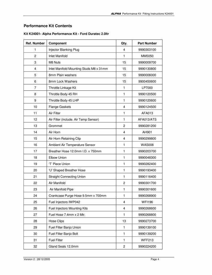
Performance Kit Contents Kit K24001- Alpha Performance Kit - Ford Duratec 2.0ltr
Ref. Number Component Qty. Part Number
1 Injector Blanking Plug 4 9990303100
2 Inlet Manifold 1 MM5050
3 M8 Nuts 15 9990009700
4 Inlet Manifold Mounting Studs M8 x 31mm 15 9990130800
5 8mm Plain washers 15 9990006000
6 8mm Lock Washers 15 9900450600
7 Throttle Linkage Kit 1 LP7000
8 Throttle Body 45 RH 1 9990120500
9 Throttle Body 45 LHP 1 9990120600
10 Flange Gaskets 4 9990124500
11 Air Filter 1 AFA013
12 Air Filter (include. Air Temp Sensor) 1 AFA013/ATS
13 Grommet 2 9990281200
14 Air Horn 4 AH901
15 Air Horn Retaining Clip 4 9990299800
16 Ambient Air Temperature Sensor 1 WAS008
17 Breather Hose 12.0mm I.D. x 750mm 1 9990203700
18 Elbow Union 1 9990048300
19 ‘T’ Piece Union 1 9990282400
20 ‘U’ Shaped Breather Hose 1 9990193400
21 Straight Connecting Union 1 9990116400
22 Air Manifold 2 9990301700
23 Air Manifold Pipe 1 9990301600
24 Crankcase Purge Hose 9.5mm x 700mm 1 9990268900
25 Fuel Injectors IWP042 4 WFI196
26 Fuel Injectors Mounting Kits 4 9990268600
27 Fuel Hose 7.4mm x 2 Mtr. 1 9990268800
28 Hose Clips 13 9990273700
29 Fuel Filter Banjo Union 1 9990139100
30 Fuel Filter Banjo Bolt 1 9990139200
31 Fuel Filter 1 WFF213
32 Gland Seals 12.0mm 2 9990224200

ALPHA Performance Kit Fitting Instructions K24001
Version 2 : 28/12/2005 Page 5
33 Fuel Filter Union (straight) 1 9990138900
34 Gland Seal 14.0mm 1 9990173800
35 Fuel Filter Mounting Kit 1 9990159400
36 Fuel Pressure Regulator 1 WFR335
37 Coolant Temperature Sensor 1 WTS185
38 Lambda (oxygen) Sensor 1 ALS331
39 Lambda Sensor Mounting Boss 1 9990200700
40 Inertia Switch 1 9990205700
41 Electronic Control Unit (ECU) 1 PI400
42 Wiring Harness 1 9990304000
43 Cable Ties 10 9990033400
44 Gearshift / Diagnostic Warning Light 1 9990128200
ALPHA Performance Kit Fitting Instructions K24001
Version 2 : 28/12/2005 Page 6
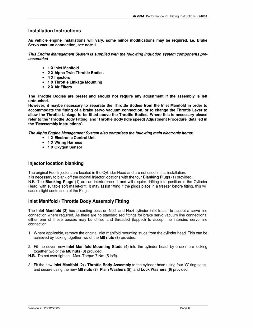
Installation Instructions
As vehicle engine installations will vary, some minor modifications may be required. i.e. Brake Servo vacuum connection, see note 1. This Engine Management System is supplied with the following induction system components pre-assembled –
• 1 X Inlet Manifold
• 2 X Alpha Twin Throttle Bodies
• 4 X Injectors
• 1 X Throttle Linkage Mounting
• 2 X Air Filters The Throttle Bodies are preset and should not require any adjustment if the assembly is left untouched. However, it maybe necessary to separate the Throttle Bodies from the Inlet Manifold in order to
accommodate the fitting of a brake servo vacuum connection, or to change the Throttle Lever to allow the Throttle Linkage to be fitted above the Throttle Bodies. Where this is necessary please refer to the ‘Throttle Body Fitting’ and ‘Throttle Body (Idle speed) Adjustment Procedure’ detailed in the ‘Reassembly Instructions’. The Alpha Engine Management System also comprises the following main electronic items:
• 1 X Electronic Control Unit
• 1 X Wiring Harness
• 1 X Oxygen Sensor
Injector location blanking The original Fuel Injectors are located in the Cylinder Head and are not used in this installation. It is necessary to blank off the original Injector locations with the four Blanking Plugs (1) provided. N.B. The Blanking Plugs (1) are an interference fit and will require drifting into position in the Cylinder Head, with suitable soft mallet/drift. It may assist fitting if the plugs place in a freezer before fitting, this will cause slight contraction of the Plugs.
Inlet Manifold / Throttle Body Assembly Fitting The Inlet Manifold (2) has a casting boss on No.1 and No.4 cylinder inlet tracts, to accept a servo line connection where required. As there are no standardised fittings for brake servo vacuum line connections, either one of these bosses may be drilled and threaded (tapped) to accept the intended servo line connection. 1. Where applicable, remove the original inlet manifold mounting studs from the cylinder head. This can be
achieved by locking together two of the M8 nuts (3) provided. 2. Fit the seven new Inlet Manifold Mounting Studs (4) into the cylinder head, by once more locking
together two of the M8 nuts (3) provided. N.B. Do not over tighten - Max. Torque 7 Nm (5 lb/ft). 3. Fit the new Inlet Manifold (2) / Throttle Body Assembly to the cylinder head using four ‘O’ ring seals,
and secure using the new M8 nuts (3) Plain Washers (5), and Lock Washers (6) provided.
ALPHA Performance Kit Fitting Instructions K24001
Version 2 : 28/12/2005 Page 7
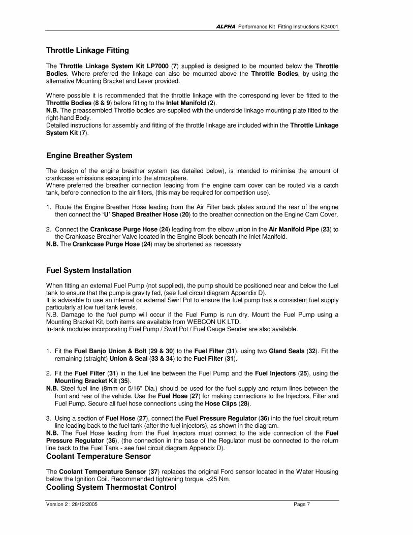
Throttle Linkage Fitting The Throttle Linkage System Kit LP7000 (7) supplied is designed to be mounted below the Throttle Bodies. Where preferred the linkage can also be mounted above the Throttle Bodies, by using the alternative Mounting Bracket and Lever provided. Where possible it is recommended that the throttle linkage with the corresponding lever be fitted to the Throttle Bodies (8 & 9) before fitting to the Inlet Manifold (2). N.B. The preassembled Throttle bodies are supplied with the underside linkage mounting plate fitted to the right-hand Body. Detailed instructions for assembly and fitting of the throttle linkage are included within the Throttle Linkage System Kit (7).
Engine Breather System The design of the engine breather system (as detailed below), is intended to minimise the amount of crankcase emissions escaping into the atmosphere. Where preferred the breather connection leading from the engine cam cover can be routed via a catch tank, before connection to the air filters, (this may be required for competition use). 1. Route the Engine Breather Hose leading from the Air Filter back plates around the rear of the engine
then connect the ‘U’ Shaped Breather Hose (20) to the breather connection on the Engine Cam Cover. 2. Connect the Crankcase Purge Hose (24) leading from the elbow union in the Air Manifold Pipe (23) to
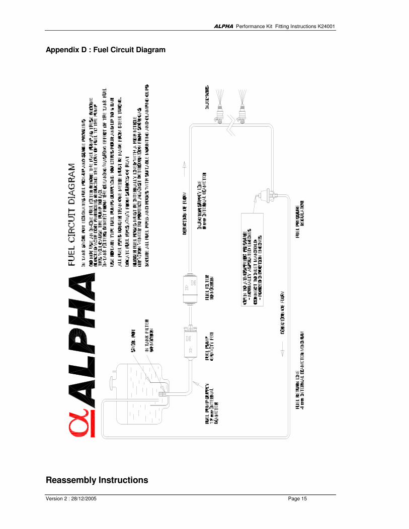
the Crankcase Breather Valve located in the Engine Block beneath the Inlet Manifold. N.B. The Crankcase Purge Hose (24) may be shortened as necessary Fuel System Installation When fitting an external Fuel Pump (not supplied), the pump should be positioned near and below the fuel tank to ensure that the pump is gravity fed, (see fuel circuit diagram Appendix D). It is advisable to use an internal or external Swirl Pot to ensure the fuel pump has a consistent fuel supply particularly at low fuel tank levels. N.B. Damage to the fuel pump will occur if the Fuel Pump is run dry. Mount the Fuel Pump using a Mounting Bracket Kit, both items are available from WEBCON UK LTD. In-tank modules incorporating Fuel Pump / Swirl Pot / Fuel Gauge Sender are also available. 1. Fit the Fuel Banjo Union & Bolt (29 & 30) to the Fuel Filter (31), using two Gland Seals (32). Fit the
remaining (straight) Union & Seal (33 & 34) to the Fuel Filter (31). 2. Fit the Fuel Filter (31) in the fuel line between the Fuel Pump and the Fuel Injectors (25), using the
Mounting Bracket Kit (35). N.B. Steel fuel line (8mm or 5/16” Dia.) should be used for the fuel supply and return lines between the
front and rear of the vehicle. Use the Fuel Hose (27) for making connections to the Injectors, Filter and Fuel Pump. Secure all fuel hose connections using the Hose Clips (28).
3. Using a section of Fuel Hose (27), connect the Fuel Pressure Regulator (36) into the fuel circuit return
line leading back to the fuel tank (after the fuel injectors), as shown in the diagram. N.B. The Fuel Hose leading from the Fuel Injectors must connect to the side connection of the Fuel Pressure Regulator (36), (the connection in the base of the Regulator must be connected to the return line back to the Fuel Tank - see fuel circuit diagram Appendix D). Coolant Temperature Sensor The Coolant Temperature Sensor (37) replaces the original Ford sensor located in the Water Housing below the Ignition Coil. Recommended tightening torque, <25 Nm.
Cooling System Thermostat Control

ALPHA Performance Kit Fitting Instructions K24001
Version 2 : 28/12/2005 Page 8
The cooling system is controlled by a ‘waxstat’ Thermostat with an electrical over-ride. The electric control is normally provided by the Ford ECU, however this function can be controlled by the fitting of a Thermo-switch, ideally situated in the by-pass (heater circuit). Alternatively an electric water pump system can be used. Please contact Webcon UK for details relating to either option. A conventional thermostat system is also available from Raceline Engineering. The Coolant Temperature Sensor (37) will also fit this item.
Lambda (Oxygen) Sensor The Lambda Sensor (38) can either replace the existing lambda sensor or can be fitted into the exhaust pipe. A 16mm (5/8”) hole should be drilled in the exhaust pipe. Ideally the sensor should be mounted vertically or as near to vertical as possible. The Lambda Sensor Boss (39) should then be welded into the hole with an airtight weld. A layer of anti-seize compound (NOT copper based) should be put on the threads of the lambda sensor before it is screwed and tightened into the boss. Recommended tightening torque, 40 Nm.
Inertia Switch It is important that the Inertia Switch (40) is securely mounted to the vehicles chassis to ensure that the switch is tripped in the event of a vehicle accident. N.B. The switch must be mounted in an upright position, with the rubber switch cover upper most. Ensure the Inertia Switch (steel ball) plunger is depressed to make circuit continuity.
Electronic Control Unit (ECU) It is essential that the management system is supplied with a good source of electric power at all times. A minimum working voltage should be no less than 10 volts, this is especially so during cold start cranking. The Electronic Control Unit ECU (41) must always be located away from any direct heat source of the engine. It is not waterproof and for this reason it must be located inside the passenger compartment of the vehicle. The ECU is supplied with the correct ignition and fuel injection calibration map that is fully optimised for the Duratec 2000cc engine. For up-rated Raceline engine specifications, please contact the ALPHA group or Raceline for more information if required. Wiring Harness Installation and Connection The Wiring Harness (42) must not run near any direct heat source. Ensure the wiring harness, and in particular the engine speed sensor lead, is routed to avoid the following components and associated wiring –
• Ignition HT leads
• Alternator
• Starter Motor N.B. If the wiring harness is routed too close to any of the above, signals may be induced in the harness that the ECU can misinterpret, causing uneven running or it can prevent the engine from starting. . 1. The bulkhead grommet on the harness is designed for a 1.75 inch (44 mm) hole. Make any holes in
the bulkhead as high up as is practical to avoid water leaks. Also, ensure the grommet is fitted correctly and securely, as the hole will very quickly cut into the harness if not adequately protected.
ALPHA Performance Kit Fitting Instructions K24001
Version 2 : 28/12/2005 Page 9
2. Route the Wiring Harness for connection to the items as detailed below. Carefully avoid sharp edges and moving parts, then allowing for engine movement, secure with the Cable Ties (43), where necessary.
N.B.The 35-Way connector (A) will fit through the grommet hole.

ALPHA Performance Kit Fitting Instructions K24001
Version 2 : 28/12/2005 Page 10
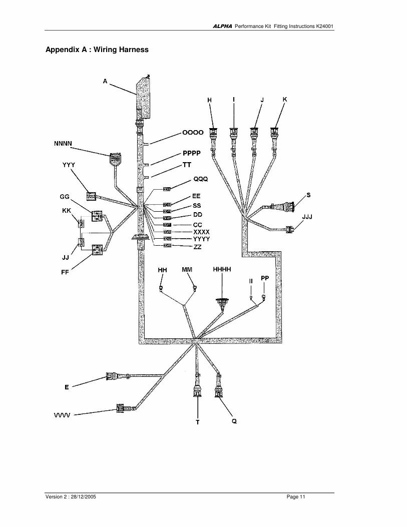
Harness Connections - Refer to Appendix A for layout of harness A - Connect to the ECU (41) 35 pin socket
E - Connect to engine rpm sensor in engine block H - Connect to Injector 4 I - Connect to Injector 3 J - Connect to Injector 2 K - Connect to Injector 1 Q - Connect to the Coolant Temperature Sensor (37) S - Connect to the Throttle Position Sensor mounted on the Throttle Body T - Not Used CC - Ignition Retard – Test only (not used) DD - Not used EE - Gearshift / Diagnostic Warning Light [Low Throttle Position] (43) – see detail below. FF - ECU Relay. Relay holder should be securely fixed to chassis (Relay pre-fitted to the holder) GG - Fuel Pump Relay. Relay holder should be securely fitted to chassis (Relay pre-fitted to the holder) HH - MAIN GROUND CONNECTION - MUST BE FITTED TO THE NEGATIVE TERMINAL NOT
THE CHASSIS! II - Fuel Pump Positive connection, fit securely to the fuel pump positive terminal JJ - ECU Relay Fuse (15 Amp Blade Type) fitted to the side of the ECU relay holder KK - Fuel Pump Relay Fuse (15 Amp Blade Type) fitted to the side of the Fuel Pump relay holder MM - MAIN 12V CONNECTION - MUST BE FITTED TO THE BATTERY POSITVE TERMINAL PP - Fuel Pump Negative connection, fit securely to the fuel pump negative terminal SS - Connect to Tachometer / Rev. Counter JJJ - Connect to the Air Temperature Sensor.(16) QQQ - IGNITION SWITCHED 12 VOLT POSITIVE BATTERY SUPPLY - MUST BE TAKEN
DIRECT FROM THE IGNITION SWITCH YYY - Connect to the Inertia Switch (40), should be securely mounted up-right to chassis
HHHH - Ignition Coil - Connect to the Ignition Coil mounted to the back of the cylinder head NNNN - ECU Communications. Locate in a suitable place so that an ALPHA PRO4 system dealer
has easy access to the connector for communication purposes VVVV - Connect to the Lambda (oxygen) Sensor (38) mounted in exhaust system WWWW - Stepper Motor (Not Used) YYYY - Auxiliary 12V Output (Ignition Switched) – Use with EE for Warning Light (44). XXXX - Wastegate Control (Not Used) ZZ - Auxiliary Ground. (Not Used) Gearshift / Diagnostic Warning Light (Low Throttle Position) The Warning Light (44) is supplied fitted to The Wiring Harness connections EE and YYYY. It is intended that the Warning Light (44) be fitted to the vehicle instrument facia, by extending the wiring as required. N.B. The Warning Light (44) has dual functionality –
• It will illuminate at 6800rpm (400rpm below the pre-set rev limiter).
• It will also illuminate if the Throttle Position Sensor (TPS) is below the correct setting voltage (0.745-0.755) or when connector S completely disconnected.
ALPHA Performance Kit Fitting Instructions K24001
Version 2 : 28/12/2005 Page 11
Appendix A : Wiring Harness
ALPHA Performance Kit Fitting Instructions K24001
Version 2 : 28/12/2005 Page 12
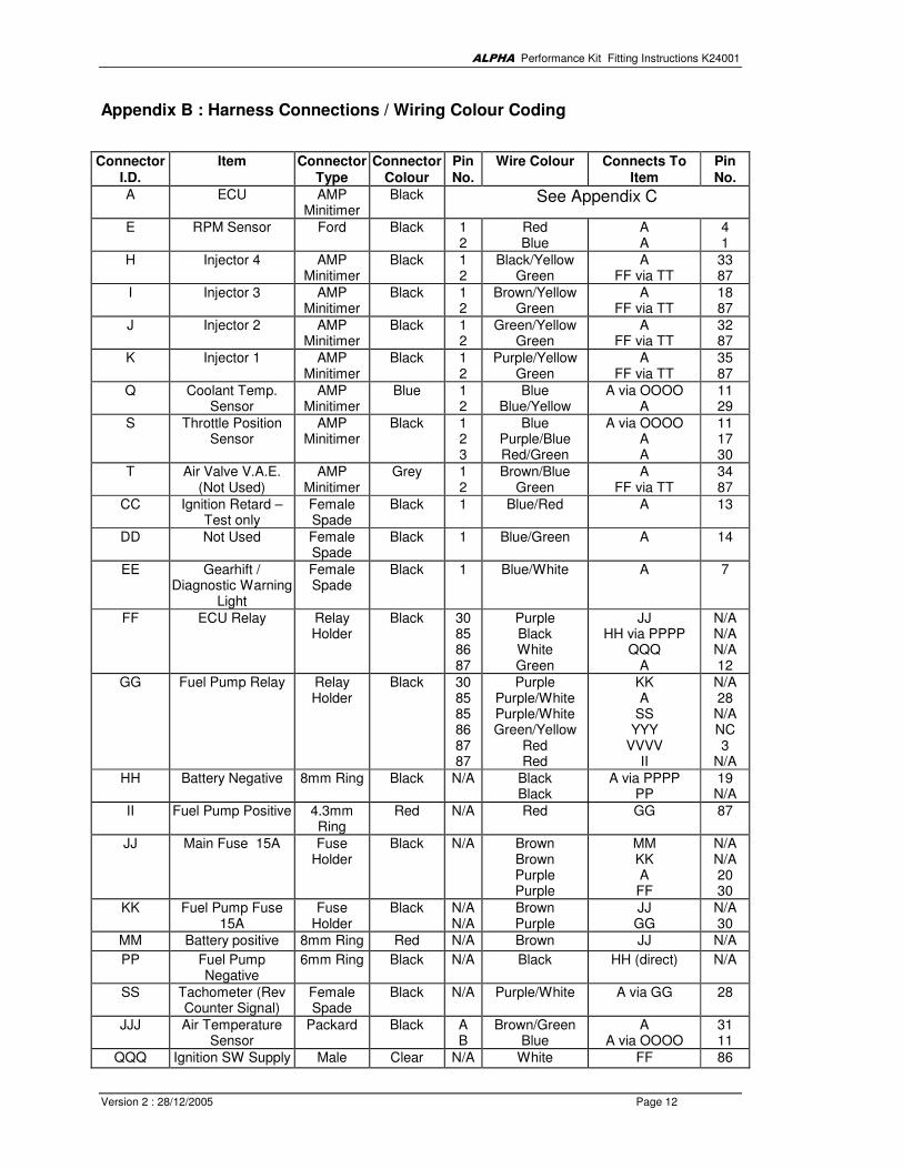
Appendix B : Harness Connections / Wiring Colour Coding
Connector I.D.
Item Connector Type
Connector Colour
Pin No.
Wire Colour Connects To Item
Pin No.
A ECU AMP Minitimer
Black See Appendix C
E RPM Sensor Ford Black 1 2
Red Blue
A A
4 1
H Injector 4 AMP Minitimer
Black 1 2
Black/Yellow Green
A FF via TT
33 87
I Injector 3 AMP Minitimer
Black 1 2
Brown/Yellow Green
A FF via TT
18 87
J Injector 2 AMP Minitimer
Black 1 2
Green/Yellow Green
A FF via TT
32 87
K Injector 1 AMP Minitimer
Black 1 2
Purple/Yellow Green
A FF via TT
35 87
Q Coolant Temp. Sensor
AMP Minitimer
Blue 1 2
Blue Blue/Yellow
A via OOOO A
11 29
S Throttle Position Sensor
AMP Minitimer
Black 1 2 3
Blue Purple/Blue Red/Green
A via OOOO A A
11 17 30
T Air Valve V.A.E. (Not Used)
AMP Minitimer
Grey 1 2
Brown/Blue Green
A FF via TT
34 87
CC Ignition Retard – Test only
Female Spade
Black 1 Blue/Red A 13
DD Not Used Female Spade
Black 1 Blue/Green A 14
EE Gearhift / Diagnostic Warning
Light
Female Spade
Black 1 Blue/White A 7
FF ECU Relay Relay Holder
Black 30 85 86 87
Purple Black White Green
JJ HH via PPPP
QQQ A
N/A N/A N/A 12
GG Fuel Pump Relay Relay Holder
Black 30 85 85 86 87 87
Purple Purple/White Purple/White Green/Yellow
Red Red
KK A
SS YYY
VVVV II
N/A 28 N/A NC 3
N/A
HH Battery Negative 8mm Ring Black N/A Black Black
A via PPPP PP
19 N/A
II Fuel Pump Positive 4.3mm Ring
Red N/A Red GG 87
JJ Main Fuse 15A Fuse Holder
Black N/A Brown Brown Purple Purple
MM KK A FF
N/A N/A 20 30
KK Fuel Pump Fuse 15A
Fuse Holder
Black N/A N/A
Brown Purple
JJ GG
N/A 30
MM Battery positive 8mm Ring Red N/A Brown JJ N/A
PP Fuel Pump Negative
6mm Ring Black N/A Black HH (direct) N/A
SS Tachometer (Rev Counter Signal)
Female Spade
Black N/A Purple/White A via GG 28
JJJ Air Temperature Sensor
Packard Black A B
Brown/Green Blue
A A via OOOO
31 11
QQQ Ignition SW Supply Male Clear N/A White FF 86
ALPHA Performance Kit Fitting Instructions K24001
Version 2 : 28/12/2005 Page 13
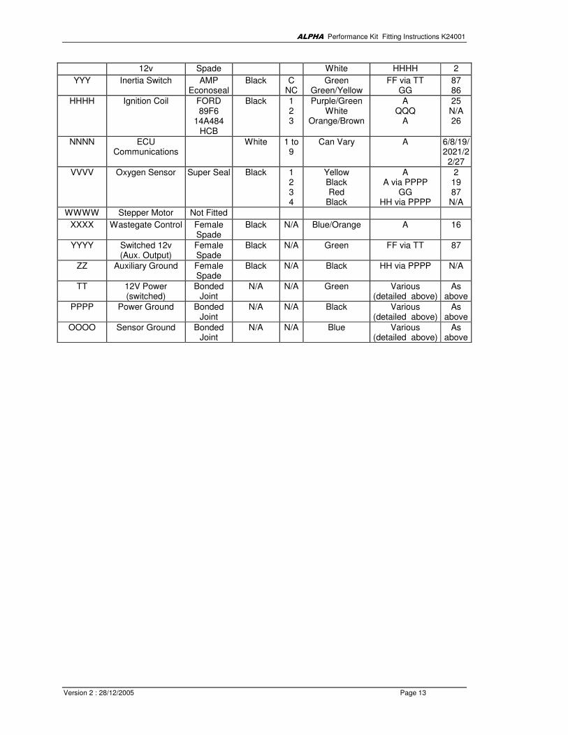
12v Spade White HHHH 2
YYY Inertia Switch AMP Econoseal
Black C NC
Green Green/Yellow
FF via TT GG
87 86
HHHH Ignition Coil FORD 89F6
14A484 HCB
Black 1 2 3
Purple/Green White
Orange/Brown
A QQQ
A
25 N/A 26
NNNN ECU Communications
White 1 to 9
Can Vary A 6/8/19/2021/2
2/27
VVVV Oxygen Sensor Super Seal Black 1 2 3 4
Yellow Black Red
Black
A A via PPPP
GG HH via PPPP
2 19 87 N/A
WWWW Stepper Motor Not Fitted
XXXX Wastegate Control Female Spade
Black N/A Blue/Orange A 16
YYYY Switched 12v (Aux. Output)
Female Spade
Black N/A Green FF via TT 87
ZZ Auxiliary Ground Female Spade
Black N/A Black HH via PPPP N/A
TT 12V Power (switched)
Bonded Joint
N/A N/A Green Various (detailed above)
As above
PPPP Power Ground Bonded Joint
N/A N/A Black Various (detailed above)
As above
OOOO Sensor Ground Bonded Joint
N/A N/A Blue Various (detailed above)
As above

ALPHA Performance Kit Fitting Instructions K24001
Version 2 : 28/12/2005 Page 14
Appendix C : Pin Outs from ECU
Pin Description Connector Pin No.
Wire Colour
1 Engine Speed Sensor Ground E 2 Blue
2 Lambda Sensor Input VVVV 1 Yellow
3 Stepper Motor (Not Used) - - Slate/Red
4 Engine Speed Sensor Input E 1 Red
5 Not used - - -
6 Communication NNNN 7 can vary
7 Gear Shift / Diagnostic Light EE N/A Blue/White
8 Communications (Not Used) NNNN 4 can vary
8 Stepper Motor (Not Used) - - Slate/White
9 Not Used - - -
10 Stepper Motor (Not Used) - - Slate/Green
11 Sensor Ground (TPS) S via OOOO 1 Blue
11 Water Temp Sensor Ground Q via OOOO 1 Blue
11 Air Temp Sensor Ground JJJ via OOOO B Blue
11 Air Pressure Sensor Ground - - -
12 Ignition Voltage (Key-on +12v) FF via TT 87 Green
13 Ignition Retard – Test only CC N/A Blue/Red
14 Input Switch (Not Used) DD 1 Blue/Green
15 Pressure Sensor Input (Not Used) - - -
16 Wastegate Control XXXX N/A Blue/Orange
17 Throttle Position Input S 2 Purple/Blue
18 Injector Channel 3 I 1 Brown/Yellow
19 Battery Negative HH via PPPP N/A Black
20 Voltage Supply (Battery +12V) JJ N/A Purple
20 Communications NNNN 8 can vary
21 Communications NNNN 3 can vary
22 Communications NNNN 6 can vary
23 Ground (Not Used) - - -
24 Ignition Signal Ground HH via PPPP 1 Black/Red
25 Ignition Signal Output 1 HHHH 1 Purple/Green
26 Ignition Signal Output 2 HHHH 3 Orange/Brown
27 Communications (Not Used) NNNN 5 can vary
28 Fuel Pump GG 1 Purple/White
28 Tachometer Signal SS via GG 1 Purple/White
29 Coolant Temp Sensor Input Q 2 Blue/Yellow
30 Reference Voltage (5v) S 3 Red/Green
31 Air Temperature Sensor Input JJJ A Brown/Green
32 Injector Channel 2 J 1 Green/Yellow
33 Injector Channel 4 H 1 Black/Yellow
34 Cold Start Air Valve (not used) T 1 Brown/Blue
35 Injector Channel 1 K 1 Purple/Yellow
ALPHA Performance Kit Fitting Instructions K24001
Version 2 : 28/12/2005 Page 15
Appendix D : Fuel Circuit Diagram
Reassembly Instructions
ALPHA Performance Kit Fitting Instructions K24001
Version 2 : 28/12/2005 Page 16
Throttle Body Fitting 1. Mount each Throttle Body (8 & 9) to the Inlet Manifold (2), using the Flange Gaskets (10). Secure
the Throttle Bodies in position with the remaining M8 Nuts (3), Plain Washers (5) and Lock Washers (6), tighten gradually in a diagonal formation.
2. With both Throttle Bodies (8 & 9) fitted to the Inlet Manifold (2), the throttles can be initially balanced,
by first ensuring that the idle speed adjustment screws, (located on the central chamber of each throttle body), are unscrewed. Next manually holding the throttle closed on the left-hand throttle body, thus compressing the sprung loaded plunger of the balance lever on the right-hand throttle body.
3. Next whilst holding the throttle closed, turn the balance adjustment screw until it contacts the balance
tab of the throttle lever on the right-hand throttle body. This should ensure that all throttle plates are fully closed. Open and close the throttle a few times to make sure they are fully closing (throttle plate contact with the barrel wall should be audible in each barrel).
N.B. On completion of the fitting of the performance kit, the throttle stop screws (idle screws) require setting
as detailed in ‘Throttle Body (Idle speed) Adjustment Procedure’. Once the engine has been started the throttle bodies must be balanced using a suitable air flow meter.
An air flow meter is available from WEBCON UK LTD. 'Synchrometer' Pt. No. 9800100000.
Air Filter Fitting 1. Remove the top plate and filter element from both Air Filter Units (11 & 12), then fit the two Grommets
(13) into the two holes in the filter base plates. 2. Fit the Air Horns (14) into the Air Filter Unit Base Plates (11 & 12), the base plate will locate in the
groove channel of the air horns. N.B. The Air Horns are a slight interference fit in the Air Filter Base Plates and need to be pushed gradually into position. Care should also be taken when fitting to avoid cuts to the hands, as the air filter base plates may have sharp edges. 3. Push Air Horns (14) and Air Filter Unit Base Plates (11 & 12), onto the Throttle Bodies (8 & 9) and
secure with the Retaining Clips (15). N.B. Do not fit the air filter elements and top plates until the air flow through the Throttle Bodies has been
checked, to ensure each barrel is flowing exactly the same amount of air. Where this is not the case please refer to the ‘Throttle Body (Idle speed) Adjustment Procedure’
Air Temperature Sensor The Air Temperature Sensor (16) should be fitted into the Base Plate of the Air Filter Unit (12), or as close to the Inlet Trumpets where possible.
ALPHA Performance Kit Fitting Instructions K24001
Version 2 : 28/12/2005 Page 17
Engine Breather System The design of the engine breather system (as detailed below), is intended to minimise the amount of crankcase emissions escaping into the atmosphere. Where preferred the breather connection leading from the engine cam cover can be routed via a catchment bottle, before connection to the air filters. 3. Cut two lengths of Breather Hose (17) 550mm & 170mm long. Fit the Elbow Union (18) into the
170mm section then join both sections together with the straight through connections of the ‘T’ Piece Union (19). Next join the ‘U’ Shaped Breather Hose (20) to the 550mm section using the Straight Connecting Union (21).
4. Fit the assembled breather hose into the Grommets (13) in the Air Filter Base Plates, (the Elbow
Union (18) fits into the left-hand Air Filter Base Plate and the ‘T’ Piece Union (19). Into the right-hand Base Plate). Route the pipework around the rear of the engine then connect the ‘U’ Shaped Breather Hose (20) to the breather connection on the Engine Cam Cover.
5. Assemble the two Air Manifolds (22) using the Air Manifold Pipe (23), then connect to the four
balance pipes on the two Throttle Bodies (8 & 9). N.B. The Air Manifold legs can be shortened as preferred. 6. Connect the Crankcase Purge Hose (24) between the elbow union in the Air Manifold Pipe (23) and
the Crankcase Breather Valve located in the Engine Block beneath the Inlet Manifold. N.B. The Crankcase Purge Hose (24) may be shortened as necessary.
Fuel Injectors 1. Fit the Fuel Injectors (25) to the Throttle Bodies (8 & 9) using the Injector Mounting kits (26)
provided. 2. Join together the fuel unions supplied in the Injector Mounting Kits, for each Throttle Body, by cutting
two sections of Fuel Hose (27) 65 mm long. Then cut a section of Fuel Hose (27) 80 mm long and join between the two 65 mm sections, secure all connections using six Hose Clips (28).
3. Fit the fuel union/hose assembly to the Fuel Injectors (25), and secure using the two collets and circlip
provided in each Injector Mounting kit.
ALPHA Performance Kit Fitting Instructions K24001
Version 2 : 28/12/2005 Page 18
Throttle Body (Idle speed) Adjustment Procedure Equipment required:-
• Syncrometer [Webcon Pt.No. 9800100000]
• Accurate Rev Counter
• Timing Gun - Ignition Timing Strobe Light IMPORTANT: The Throttle Bodies are supplied preassembled, and should not require any further adjustment. To achieve the very best results from the Alpha PRO4 Engine Management System, it is essential that the air flow through each barrel of the Throttle Bodies is exactly the same, and that the Throttle Position Sensor (TPS) is set to the correct voltage. When operating correctly good cold starting, stable hot and cold idle speed control and excellent light throttle driveability will be achieved. It will also ensure that the closed loop lambda control required for exhaust emissions testing (SVA) is operating within its optimum control range. Should it be necessary to make any adjustments, the following procedure should be adhered to. 1. Where it has been necessary to remove the Throttle Bodies, after refitting only the balance lever that
connects the two Throttle Bodies should require adjustment as detailed in operation 5 below. This is providing the throttle stop screws (located on the central chamber of each throttle) remain as received unaltered from the factory setting.
N.B. If the idle stop screws have been altered it may be necessary to reset the stop screws as detailed in the ‘Throttle Body Fitting’ instruction detailed above. 2. After resetting the Throttle Stop Screws carry out operations 3 & 4 below, if adjustment was not required
proceed to operation 5. 3. With the ignition turned on adjust the voltage at the Throttle Position Sensor (TPS). To do this, connect
a volt meter to terminal 1 blue wire and terminal 2 (centre) blue/purple wire of the harness connector S. The Throttle Position Sensor voltage reading requires setting to between 0.670 – 0.680 volts.
Once again, open and close the throttle a few times to make sure they are fully closing and that the voltage reading remains between 0.670 – 0.680 volts.
4. Open the throttle by adjusting the throttle stop screw on the left-hand Throttle body to achieve a reading
between 0.745 – 0.755 volts. Adjustment the stop screw on the right-hand Throttle Body should be made after the next operation, to still maintain the same air flow through all four barrels of the Throttle Bodies at idle. When correctly adjusted this will also ensure that when the accelerator pedal is lightly depressed all four Throttle Plates open equally. This will eliminate any tendency of a lean misfire (spitting) due to the unequal opening of the Throttle Plates.
5. Start and run the engine until normal operating temperature is reached, (use the ‘Syncrometer’ to
maintain the same amount of air flow through each Throttle Body). With the engine at normal operating temperature repeat this operation to ensure all the barrels of the throttle bodies flow the same amount of air. The air flow through each barrel should be approximately 4 Kg/Hr. If there is a higher reading on one barrel of a particular Throttle Body, ensure that the air by-pass screw on that barrel is fully closed. The adjacent air by-pass screw on the same body should then be adjusted (opened) to attain the same air flow reading on both barrels
6. With the engine at normal operating temperature the ECU is designed to maintain an idle speed of
900rpm by controlling the ignition advance. However, when the Throttle Bodies and TPS are correctly set, the ignition timing advance should be 5 degrees After Top Dead Centre (ATDC). To accurately check the timing it will be necessary to mark the timing cover. If the ignition timing advance is greater or less than 5 deg. ATDC* the idle stop screw may require slight adjustment, the TPS voltage must then be reset to between 0.745 – 0.755 volts.
* An average reading maybe required due to the ECU idle control strategy, particularly if some re-adjustment to the throttle stop screw / TPS is required. N.B. If difficulty is experience achieving the correct settings, a default idle speed TPS setting can be obtaining by disconnecting the TPS (connector S). This will allow the throttle air flow settings to be changed
ALPHA Performance Kit Fitting Instructions K24001
Version 2 : 28/12/2005 Page 19
without the need to make re-adjustments to the TPS. After, then achieving the correct throttle (air flow) setting the TPS must be reconnected, and the final adjustment made to the TPS (0.745 – 0.755 volts). When the TPS is disconnected the Diagnostic Warning Light (43) will illuminate and will remain lit when reconnected if the TPS voltage is less than 0.740v.

ALPHA Performance Kit Fitting Instructions K24001
Version 2 : 28/12/2005 Page 20
Appendix E : Spares
Wiring Loom Spares
Component Webcon Part No.
35 way connector 9990098600
3 way connector 9990166900
3 way connector boot 9990175700
2 way connector (brown) 9990166700
2 way connector boot 9990175600
2 way connector boot (90 deg) 9990157900
Terminal pins (standard) for above connectors (0.5-1.5 wire) 9990098900
Terminal pins (high spec.) for above connectors (0.5-1.0 wire) 9990204700
Terminal pins (high spec.) for above connectors (1.0-2.5 wire) 9990204800
Relay Holder 9990179400
Fuse Holder 9990206900
Packard 2 way connector kit (Air temperature sensor) 9990224500
Augat 4 way connector (Lambda sensor) 9990206600
Terminal pin for Augat connector 9990206500
Wire seal for Augat connector 9990206700
AMP Econoseal connector kit (Inertia switch) 9990208300
Ignition coil connector Moulding 9990241600
terminal pin (small)1&3 9990241700
terminal pin (large) 2 9990241800
wire seal 9990241900
N.B. For details of other fuel system items not listed above please contact Webcon UK Ltd.
NOTES :

ALPHA Performance Kit Fitting Instructions K24001
Version 2 : 28/12/2005 Page 21

ALPHA Performance Kit Fitting Instructions K24001
Version 2 : 28/12/2005 Page 22
Webcon UK Limited
Dolphin Road, Sunbury on Thames, Middlesex, TW16 7HE Tel: +44 (0) 1932 787100 Fax: +44 (0) 1932 770315 E-mail: [email protected]
www.webcon.co.uk