K09821;1/37 Video Camera Instruction Manual · Video Camera Instruction Manual ... (CAT-5e or...
37
K09821;1/37 - 1 - Video Camera Instruction Manual GigE Vision compliant 11 Megapixel Progressive Scan Monochrome/Color Camera FC11000GE FS11000GE ● We greatly appreciate your confidence choosing our TAKEX CCD Video Camera. ● Please read this manual and the attached guarantee certificate carefully and manage the camera properly. Keep this manual at hand and reread it whenever you are uncertain about the operation. Table of Contents 1. Features ······························································································ 3 2. Outline································································································· 3 3. Description of Each Component ······························································· 4 4. How to Operate ····················································································· 6 5. Various Settings ··················································································· 11 6. How to Change Settings········································································· 14 7. Serial Communication Command ····························································· 22 8. Timing Chart ························································································ 29 9. Image Display Software and API terms ····················································· 34 10. Notes ································································································· 36 11. Specifications······················································································· 37 12. External Dimensions ············································································· 37 TAKENAKA SYSTEM CO., LTD Document No.: K09821 FX11000GE Instruction Manual (4th version)
Transcript of K09821;1/37 Video Camera Instruction Manual · Video Camera Instruction Manual ... (CAT-5e or...
K09821;1/37
- 1 -
Video Camera Instruction Manual
GigE Vision compliant 11 Megapixel Progressive Scan Monochrome/Color Camera
FC11000GE FS11000GE
We greatly appreciate your confidence choosing our TAKEX CCD Video Camera. Please read this manual and the attached guarantee certificate carefully and manage the camera properly.
Keep this manual at hand and reread it whenever you are uncertain about the operation.
Table of Contents
1. Features ······························································································ 3
2. Outline ································································································· 3
3. Description of Each Component ······························································· 4
4. How to Operate ····················································································· 6
5. Various Settings ··················································································· 11
6. How to Change Settings········································································· 14
7. Serial Communication Command ····························································· 22
8. Timing Chart ························································································ 29
9. Image Display Software and API terms ····················································· 34
10. Notes ································································································· 36
11. Specifications ······················································································· 37
12. External Dimensions ············································································· 37
TAKENAKA SYSTEM CO., LTD Document No.: K09821 FX11000GE Instruction Manual (4th version)

K09821;2/37
- 2 -
[History of revision]
Version Content of change Description Date Document No. Remark
1st version 2009-04-08 K09408 FC11000GE FS11000GE
2nd version K09531
3rd version K09713
4th version K09821
Description of special remarks used in this manual
(Note) ················ Particulars which require the user’s attention are explained. (!) ················ Particulars which require the user’s close attention in terms of comparison with the conventional
products are explained.
[Terminology] ················ Terms specifically defined for the purpose of describing the operation of this camera are explained. [Explanation] ················ Particulars for which details may be needed for user’s understanding of the operation of this
camera are explained.

K09821;3/37
- 3 -
1. Features
FC11000GE/FS11000GE is a full frame shutter monochrome(FC11000GE)/color(FS11000GE) camera incorporated with 11-megapixel, diagonal 43mm-size CCD image sensor .
A full frame shutter image can be obtained at a rate of 5 frames per second (in DUAL mode). Gigabit Ethernet is adopted as the output interface of image signal. Image signal can be output at 12/10/8-bit resolution. The set values of the camera can be externally controlled with the use of the serial communication via Ethernet. The character information of the current setting status of the camera can be superimposed over the captured image on
the screen. (On Screen Display function) The monitoring function for measuring the internal temperature of the camera. The asynchronous shutter is applicable both in the preset shutter mode and the pulse width control mode. The camera is designed so that the strobe signal can be output even in the continuous shutter mode, and this
contributes to the power saving for LED lighting and others as well as the reduction of smear. The ID information set by the user for each camera can be saved and read out whenever necessary ( via serial
communication link). It is equipped with correction function that automatically reduces the difference between right image and left image. FS11000GE is a color camera(Bayer, RAW output). ※FS11000GE is not equipped with IR cut filter. If it has the coloring problem by the effect of infrared, use the camera with the
IR cut filter placing in front of lens. 2. Outline
CCD
DRIVER
PLDTG
CPU
A/D
( OFF SET )Preamplifier
(GA IN)
UART
S/H
SYNC
Vinit Camera
Link
I/F
Gigabit
Ethernet
IP
ENGINE
RXD
TXD
Vi nit1STRB MO DE,EXP UD-SW
S/H A/D
( OFF SET+ OFF SET _B)
(GA IN+GA IN_ B)
PLD
DUA L&S ING LE
DUA L RJ-45 Connector
GigE I/F
12/10/8 bit
DUAL out SINGLE out
Image sensor Imaging area size
Number of pixels Pixel size
CCD Image sensor: Monochrome/Color
36.07mm × 24.05mm (Diagonal 43mm) 4008(H) × 2672(V)
9.0μm(H) × 9.0μm(V) Effective pixels 10.7 megapixels
Read out scanning
Horizontal 14.1 KHz 7.5 KHz
Vertical 5.1 Hz 2.7 Hz
Clock 32.50 MHz
Electronic shutter 1/2000 to 1/5 second
(Continuous shutter and asynchronous shutter)
Video output signal Digital 12/10/8 bit
Gigabit Ethernet interface(GigE Vision compliant) 2Tap 1Tap
Scanning mode Normal scanning for all pixels Double speed scanning
OB(Optical black)
Effective image pickup area
4008 x 2672V
SINGLE
VIDEO L
4008
20
1 7
1 6
2672
H
12
8
4 19 413
VIDEO R
2004 2004
8
Output
DUALor
B
RG
G
C olo rc odi ng
Fig.2-1 CCD architecture
Fig.2-2 Block diagram
K09821;4/37
- 4 -
1.0
0.9
0.8
0.7
0.6
0.5
0.4
0.3
0.2
0.1
0.0500400 600 700 800 900 1000
(Typica l v alue)
FC11000GE
1.0
0.9
0.8
0.7
0.6
0.5
0.4
0.3
0.2
0.1
0.0500400 600 700 800 900 1000
Wavelength(nm)
FS11000GE
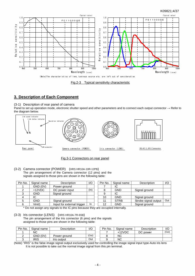
(Note)The characteristics of lens,luminous source etc. are left out of consideration.
Relative
sensitivity
Relative
sensitivity
Wavelength(nm)
(Typic al value)
3. Description of Each Component (3-1) Description of rear panel of camera Panel to set up operation mode, electronic shutter speed and other parameters and to connect each output connector → Refer to the diagram below.
POW ER
EX P. M ODE
U
D LE NS 10
11 12
9
8
7
65
4
3
2
1
1
2
34
5
6
Camera connector(POWER) Iris connector(LENS)Rear panel
Ope rat ion ind ica tor
Link sp eed in dica tor
L ink sta tus in dica tor
RJ-45 LAN Connector
8 7 6 5 4 3 2 1
LA N co nne cto r
(3-2) Camera connector (POWER) (HRS HR10A-10R-12PB)
The pin arrangement of the Camera connector (12 pins) and the signals assigned to those pins are shown in the following table:
Pin No. Signal name Description I/O
Pin No. Signal name Description I/O 1 GND (0V) Power ground
7 IC 2 +12VDC DC power input (In)
8 GND Signal ground 3 GND Signal ground
9 IC 4 IC
10 GND Signal ground 5 GND Signal ground
11 STRB Strobe signal output Out
6 Vinit1 Input for external trigger In
12 GND Signal ground * Do not assign any signals to the IC pins because they are occupied internally.
(3-3) Iris connector (LENS) (HRS HR10A-7R-6SB) The pin arrangement of the Iris connector (6 pins) and the signals assigned to those pins are shown in the following table:
Pin No. Signal name Description I/O
Pin No. Signal name Description I/O 1 NC
7 +12VDC DC power (Out) 2 GND (0V) Power ground (Out)
8 NC 3 IRIS Iris output Out
9 NC (Note) ”IRIS” is the false image signal output exclusively used for controlling the image signal input type-Auto iris lens It is not possible to take out the normal image signal from this pin terminal.
Fig.2-3 Typical sensitivity characteristic
Fig.3-1 Connectors on rear panel

K09821;5/37
- 5 -
(3-4) Mode switch (MODE) The Operation mode and Gain can be set by manipulating Mode switch and UP/DOWN switch. (3-5) Shutter switch (EXP.) The shutter speed (shutter exposure time) can be set by manipulating Shutter switch. (3-6) UP/DOWN switch (U-D) The Operation mode and Gain can be set by manipulating Mode switch and UP/DOWN switch. (3-7) LAN connector (Standard type RJ-45 connector)
This is the LAN connector (RJ-45 type) conforming to Gigabit Ethernet interface (1000BASE-T/IEEE802.3ab). It is connected with the LAN connector of PC using standard LAN cable(CAT-5e or CAT-6) conforming to Gigabit Ethernet.
[Pin arrangement of LAN connector (RJ-45)]
Pin No. Signal name Description I/O 1 TP0+ Twisted pair 0 (+) In/Out 2 TP0- Twisted pair 0 (-) In/Out 3 TP1+ Twisted pair 1 (+) In/Out 4 TP2+ Twisted pair 2 (+) In/Out 5 TP2- Twisted pair 2 (-) In/Out 6 TP1- Twisted pair 1 (-) In/Out 7 TP3+ Twisted pair 3 (+) In/Out 8 TP3- Twisted pair 3 (-) In/Out
When using this equipment on a place subject to constant vibration or impact, it is recommended to employ a screw lock type LAN cable. Firmly screw a locking screw into a connector fixing screw hole when using a screw lock type cable. (3-4) Display LED Three indicator LEDs are laid on the rear panel ・Operation indicator LED (POW: Three colors: green/red/orange)
It lights up (or brinks ) to indicate that the camera is powered. When the camera is set in the asynchronous shutter mode, It lights up in red in response to the input of the external trigger signal.
・Link speed indicator LED (SPD: orange) It lights up in orange to indicate that the camera is connected to LAN port (LAN card) or HUB of Gigabit Ethernet Interface (1000BASE-T). It turns off when the camera is connected to LAN port (100BASE-T, 10BASE-T) of which communication speed is lower than 1000BASE-T or when the camera is connected to nothing.
・Link status indicator LED (LINK: green)
It lights up when the camera is connected to the other LAN port via Ethernet and the data-access is running as well.
Name Color OFF ON Blinking SPD Orange Disconnected from LAN
or Connecting at 10Mbps/100Mbps Connecting at 1000Mbps -
LINK Green Disconnected from LAN Connected to LAN Data accessing

K09821;6/37
- 6 -
4. How to Operate (4-1) Connection method
Connection Refer to the connection example between the camera and peripheral devices (Fig. 4-1). (1) Remove the cover of the lens attachment section and
attach a lens (option). (2) Connect the camera head to a power supply unit(option) with a
camera cable (option). The maximum allowable length for camera cable is 10 m.
(3) Connect the LAN connector on the rear of the camera to the LAN connector of PC through LAN cable(Cat-5e or greater). The maximum allowable length for a standard LAN cable is 100m. Also, the maximum allowable length for a hi-flex LAN cable is 30m.
(4) Turn on the power switch of the camera after confirming the connecting condition. In 1 or 2 seconds after the power is turned on, the operation indicator LED on the rear panel of the camera changes from orange to green to show that the camera is in operation.
(5) Set the camera operation modes in accordance with the setting instructions for the operation modes and the shutter speed that are described in another section.
(Note) The maximum allowable lengths of the camera cable and the LAN cable aforementioned are not for the purpose of
guaranteeing the operation of the camera. Proper image signals may not be obtained even when the cables are within the allowable ranges, depending on the installation conditions of the camera, cables in use and others. Especially for a camera cable (Power cable), the voltage of the terminal end on camera side is required to be within a voltage range of the specification (12V±10%) with the camera being connected.
(Note) As the LAN card, use a separately recommended product or a LAN port equipped with recommended Ethernet controller(PHY).
[Important] (Note) Make sure to turn off the power switch of the camera before connecting or disconnecting the camera cable.
If the cable is connected or disconnected while the power is supplied, troubles may be caused. (Note) Make sure to turn off the camera and connected devices in advance when the camera is connected. (Note) When a power supply unit other than Takenaka’s camera power supply units that are separately sold is used, make sure
that it complies with the following rated specifications: Power supply voltage: DC12V±10% Current capacity: 1.2A or over (recommended value)
Take into consideration the fact that transient current of about 1.8A flows when power is applied. Ripple voltage: 50mVp-p or less (recommended value) Connector: 12 pin connector 1 pin (GND), 2 pin (+12VDC)
(Note) Some power supply units other than TAKENAKA’s products have different layout of power connection pins. Make sure to check the compatibility of the power supply unit and the camera connection pins in advance. Carefully note that any failure associated with power application to out-of-specification pins and others is subject to charged repair.
(4-2) Input of Vinit signal (asynchronous trigger signal)
How to input Vinit signal
If the camera is used in the asynchronous shutter mode, the Vinit signal (asynchronous trigger signal) must be input from the user unit. The Vinit signal is input from Pin (6) of the “POWER” connector (12 pin connector) on the rear of the camera. If the camera is connected to the power supply unit PU100 with a Takenaka’s 12W series cable, connect the Vinit signal (asynchronous trigger signal) to the trigger input terminal of the power supply unit (PU100).
(Note) Though the asynchronous trigger signal can be given by serial communication command via GigE interface, it is not suitable for real-time image capturing as it gets delayed following packet forwarding.
(Note) When the camera is in OSD menu displaying status (when the operation indicator LED blinks in green), periodic trigger signal continues to be supplied from internal CPU so that OSD display is updated on regular basis. In this state, the external trigger signal (Vint) can not be accepted. Turn the OSD menu to hidden status to make Vint signal input effective.
Fig. 4-1. Connection example between camera and peripheral devices
Computer
LAN card
(LAN portト)Intel PRO/1000
etc.
Trigger pulsegenerating circuit
(sensor etc.)
TRIG
12W-02 etc.
LAN cable(Ctat-5e,Cat-6)
P U 1 0 0
FC series camera
FCxxxGE
T AKE X
Camera cable

K09821;7/37
- 7 -
LED Vinit signal monitor indicator When this camera is set in the asynchronous shutter mode, the LED indicator on the rear panel of the camera lights up in red for one shot in response to the input of the external trigger signal (Vinit signal). This allows the user to confirm the state of signal input. The red LED lights up for a certain period of time (for about 100 ms) each time for a trailing edge of the trigger input. If a following trigger signal is input within this period, the lighting time of the LED will be retriggered and extended. Since the lighting of the LED responses only to the trailing edge of the trigger input, it lights up only once for 100 ms even if the trigger input pulse duration is longer than the one shot time of period.
Setting of various asynchronous shutter modes Set the parameters and others in accordance with the following table:
Table 4-1 Setting of various asynchronous shutter modes Asynchronous shutter mode PWC Shutter switch Remark Preset shutter (PWC=DISABLED) DISABLED 1 to 9 Preset shutter (PWC=ENABLED)
ENABLED 1 to 8
Pulse width control 9 Shutter switch = 1 to 8: same as preset shutter (Note) When shutter switch is 0, “Continuous image output(without shutter)” is applied for the all. (Note) For setting methods for the respective parameters of “PWC” and others → See “ How to set operation mode”. Recommended timing of asynchronous shutter trigger signal (Vinit signal) for preset shutter/pulse width control
For the case of preset shutter mode, the negative logic pulse is applied within the width range from 1 H (1 horizontal synchronous interval) to 40H as described below. For this case, the exposure operation starts in synchronization with the trailing edge of the applied pulse. For the case of the pulse width control exposure mode, numeric value of the L level interval of the input Vinit pulse (shown as Tvinit in the figure) is retrieved in synchronization with the trailing edge of the internal HD pulse, and the integer multiple number of H (1 horizontal synchronous interval) that is closest to the retrieved Vinit pulse duration is transmitted as nH to the inside of the camera. Then the shutter speed is determined in response to the time nH.
Vinit
Tvinit
[For the case of preset shutter mode]
1H ≤ Tvinit ≤ 40H (The exposure time is independent of the Vinit width.) 1H=1 horizontal scan time
[For the case of pulse width control mode] (Where PWC=ENABLED, shutter switch = 9) nH ≤ Tvinit <(n+1)H (n is 1 or larger integer.) (This is the pulse width where shutter exposure time =nH)
Fig.4-3 Vinit signal timing (Note) In the pulse width control, the shutter exposure time is almost equal to the integral multiple number of the
horizontal synchronous time (H) that is closest to the Vinit pulse duration. More specifically, however, the shutter exposure time is indefinite for the time period corresponding to 1H width in the case of normal external trigger input (or the case where the Vinit signal is not in synchronization with the horizontal synchronous timing of the camera). → Refer to the timing chart described in another section for the details.
(Note) When the shutter exposure time is too long in the pulse width control mode, the S/N ratio of the image will be degraded due to the reduction of dynamic range of CCD, accumulation of thermal noise components of CCD image sensor in proportion to the shutter speed and other factors. Therefore, if a long exposure time is employed, it is recommended to conduct experiments using realistic exposure times in actual conditions to check for the appropriateness.
Example of drive circuit for Vinit input circuit
* The Vinit signal should not include unnecessary noise components such as chattering.
[Input voltage range]
H level 2.5 to 5.5 V L level -0.5 to 0.5 V
* The voltage of the terminal end on camera side is required to be within the above voltage range with the camera being connected.
Red LED lights up in red in response to trigger signal input (Vinit).
Camera connector
7 5Ω 6
Vini t1 IN
VCC
3 .3 V
4.7k 4 7p
3.3V
10 k 10 0Ω
T C7 4LVX14 o r e qui vale nt
To internal circ ui t 3.9 ZD
VCC is +5V or +3.3V
74AC04 or other s
[Exam ple of user c ir cui t] Ins ide of camera
GigE Serial I/F
P OW E R
E XP . M O DE
U
D L E NS
Op era tio n in dic ato rLE D
Fig. 4-2. LED indicator
Fig. 4-4. Vint circuit

K09821;8/37
- 8 -
STRBsignal output
(11)pin of Camera connector
100Ω
Frominternal circuit
74VHCT04A
+5V
(or equivalent)
6.8 ZD
STRB
BUSY
OFF
Fig. 4-5. Strobe signal output circuit
(4-3) Strobe signal output circuit The internal output circuit is shown in the right figure. Conventional cameras used the strobe signal (STRB) as
the exposure timing signal only. In this equipment, this can be switched between OFF, STRB signal (continuous & asynchronous) and Busy signal(asynchronous) by setting. This setting can be changed on the configuration menu (Operation Mode Setting Group 3) or by way of rewriting the configuration register with serial communication command. The default setting is OFF (no strobe signal).
This equipment is capable of outputting the strobe signal even in the continuous shutter mode as well as in the asynchronous shutter mode when the setting is changed to output the strobe timing signal(STRB).
[Explanation] Usage of strobe signal in continuous shutter mode
In the continuous shutter mode, only the incoming light for the time matching the exposure time of the camera is valid. Accordingly, when a lighting unit is used in the continuous lighting mode, the lighting during the time other than this exposure time period would be wasted. Since this equipment is capable of outputting strobe signal (STRB) even in the continuous shutter mode, this output is used as a trigger signal to control a LED light or other lighting units that can be turned on and off at high frequencies, which helps eliminating the lighting during the useless lighting time. The following benefits are derived from this type of lighting control: The consumption of the power to a light can be saved by way of lighting only during the valid time for exposure. The occurrence of smear is reduced because no light enters any time other than the exposure time periods.
(Note) When the strobe signal is used in the continuous shutter mode to make ON/OFF control on a lighting source unit,
the following must be taken into consideration: Wherever possible, use a strobe lighting unit or others that are equipped with a power source separated from that of the camera (electrically isolated power source) and a trigger input terminal (photo coupler input, etc.). If a lighting unit that shares a power source or a ground circuit with the camera is turned on or off by the strobe signal, the image output from the camera may have noise due to the influence of the fluctuation of the power supply voltage or change in the electric potential that occurs at the ON/OFF timing. Even when the insulation aforementioned is applied, the electromagnetic induction may lead to the occurrence of noise on the image signal if the electric current of the lighting unit to be control is large. In this case, a measure must be introduced to reduce electromagnetic induction noise arising from the lighting unit.
(4-4) Test pattern display function
When initially connecting this camera to an image capture board, the use of the test pattern display function of the equipment makes it easier to confirm that the output timing of the camera and the details of the signal connection match the particulars of the capture board. When the test pattern function is set to be ON, the image sensor outputs the test pattern in place of pictures as shown on the right. As for this pattern, a numerical value of 1 is simply added in an incremental manner for every horizontal pixel, and a saw-tooth profile is shown in the range from the numerical value of 0 to 1023.
(Note) In the data, a numerical value of 1 is incrementally added for every horizontal pixel in the
range of 0 to 1023 for the case of 10 bit output, and in the range of 0 to 255 for the case of 8 bit output.
(Note) The value does not start with 0 at the edge of the effective image area. (Note) The output values of the test pattern are not affected by the values of the gain setting or offset setting of the
camera.
The default setting is OFF. This setting can be changed on the configuration menu (Operation Mode Setting Group 4) or by way of rewriting the configuration register with serial communication command.
[Procedure for switching test pattern output ON/OFF] (1) Start up in the Setting group 4.( Set the mode switch to the position “D”, keeping the power to the camera off. Then
turn on the power of the camera while turning and keeping the UP/DOWN switch lever to the either of upper or lower position).
(2) Return the UP/DOWN switch lever to the neutral position when the response sound of “pip-pip” is heard (3) Change the position of the mode switch to “2” after confirming that LED indicator flashes in orange. (4) The test pattern display gets ON by stroking UP/DOWN switch upward and gets OFF by stroking that downward. (5) Switch to OFF when Test pattern is not necessary anymore. Since the setting of the test pattern output is
automatically saved, the test pattern will be output with last setting when the power is reapplied from next time.
Shutter exposure time
Continuous lighting
STRB signal
Exposure Exposure
Valid Useless lighting time Valid Useless lighting time
0
1023
Test patte rn and hor izontal pr ofile

K09821;9/37
- 9 -
(4-5) Monitoring function for internal temperature of camera This camera is equipped with an internal temperature sensor to monitor the temperature inside the body. This function makes it possible to use the camera in a safer way even in a harsh environment in terms of temperature, for example use in the open air. With the use of serial communication commands, this function also works to control the forced air-cooling fan of the camera and peripheral devices and others.
How to monitor internal temperature of camera The following two methods are available for monitoring the internal temperature of the camera:
Turn on the MENU display and confirm on the OSD over the image. (Temperature to be displayed in Celsius) Confirm with temperature data to be returned in response to the serial communication command (”RTMP”
command). (Numerical conversion required separately)
(Note) Carefully note that the temperature data obtained by this monitoring function is not for the ambient temperature but the internal temperature of the camera. As a general rule, the internal temperature of the camera is higher than the ambient temperature because of the heat generation associated with the consumed electric power inside the camera. Even when the temperature monitored by this function exceeds the value of the “Operation ambient temperature” shown in the specifications of the camera, no operational trouble will be caused as long as the ambient temperature is equal to the one of the specifications or lower, and sufficient countermeasures against temperature are taken.
Detection capability for temperature data
Minimum unit for temperature data : 0.5° Data refreshing cycle : 0.4 sec. Temperature detection accuracy: ±2°C (-40°C to +85° C), +3 to -2°C (55°C to 125°C) Effective data range : -55°C to 125°C (as long as t he operation ambient temperature of the camera is
within the range defined by the specifications.)
Temperature data by serial communication The temperature data to be returned in response to the “RTMP” command of serial communication is generated in the following format:
[Data format] The lower 10 bits out of the 16 bits of the returned data are valid. XXXXXD9D8…D0 (invalid upper 6 bits/valid lower 10 bits as the data) Db=B’D9D8…D0 in the binary system shows a signed integer value in two’s complement form. However, the effective range of the temperature data is limited to the following due to the operational restriction of the temperature sensor: Effective range of temperature data: -110 (-55°C) to +250 (125°C) (Note) The accuracy of the values of the temperature data is not guaranteed when the operation ambient temperature is
not within the range defined by the specifications. [Conversion method from returned data to temperature in Celsius] The temperature in Celsius is computed as Tc from the following formula where Dt is the signed integer number converted from the above described 10 bit binary value of “Db=B’D9D8…D0”: Internal temperature of camera: Tc=Dt×0.5°C (Example 1) Where Td, the returned value of the temperature data, is “H’0032” in the hexadecimal system, it is
expressed in the binary system as follows: Td=H’0032=B’0000.0000.0011.0010 ∴ Db=B’00.0011.0010 =+50 (Only upper 10 digits of Td are valid.) Then, Tc is calculated from the following formula: Tc=+50×0.5°C=+25°C
(Example 2) Where Td, the returned value of the temperature data, is “H’03FA” in the hexadecimal system, it is
expressed in the binary system as follows: Td=H’03F1=B’0000.0011.1111.1010 ∴ Db=B’11.1111.1010 (Only upper 10 digits of Td are valid.) → Dt=-6 Then, Tc is calculated from the following formula: Tc=Dt×0.5°C=-6×0.5°C=-3°C

K09821;10/37
- 10 -
(4-6) Operation confirmation buzzer
This equipment is designed to sound the confirmation buzzer of “pip” when a stroke is applied to the UP/DOWN switch on the rear panel, or at the time of other manipulation including the start-up after power application. The factory default setting is ON. This setting can be changed to cancel the buzzer. [Procedure for switching buzzer between ON/OFF] (1) Start up in the Setting group 3.( Set the mode switch to the position “C”, keeping the power to the camera off. Then
turn on the power of the camera while turning and keeping the UP/DOWN switch lever to the either of upper or lower position).
(2) Return the UP/DOWN switch lever to the neutral position when the response sound of “pip-pip” is heard (3) Change the position of the mode switch to “2” after confirming that LED indicator flashes in orange. (4) The buzzer sound gets ON by stroking UP/DOWN switch upward and gets OFF by stroking that downward. (5) Turn off the power following the completion of setting . Since the setting is automatically saved, the camera starts up
with the last setting when the power is reapplied from next time. (4-7) Camera ID saving function
The ID code and other information set by the user for each camera can be stored in the camera and be read out when needed. The saved identification data for each camera including installation location in the case of using more than one camera (e.g., “CAMERA-RIGHT” and “CAMERA-LEFT”) allows the user to easily control and identify the camera (s). The setting is executed through the serial communication. The settable maximum number of characters are 15, and alphabets (both upper and lower cases), numbers and some special symbols such as”+” and “-” excluding the control codes can be used. (→ Refer to the section of “Serial Communication Control” for the details.)
(4-7) Automatic Correction Function
The CCD in this equipment has 2ch output ports (right and left), and the image signal can be read out in high speed from both ports.(Dual mode) At that time, the right and left halves of image data are synthesized to make a full area picture image bringing together at a center boundary of the screen. Then the right and left output may differ in level, as the both output characteristics are not exactly the same. This equipment has the automatic correction function to reduce and obscure the level difference at the boundary. The factory default of this function is OFF. It can also correct the level difference manually deactivating the automatic correction function. Depending status of camera usage, difference in level or border line may appear on the center boundary. However, it does not arise from camera failure.
(4-8) Auto Iris Signal (IRIS) output circuit
This signal is effective as Auto Iris control signal only in no shutter mode or continuous shutter mode.
Signal output level 0 to 0.7 V (DC) Output impedance 75 Ω Asynchronous signal No signal
+3.3V
I R IS signal
3
Frominternal circuit
75Ω
AMP
+3.3V

K09821;11/37
- 11 -
5. Various Settings (5-1) Operation mode
CCD output mode ······· DUAL / SINGLE Electronic shutter operation mode
Shutter system No shutter / continuous/asynchronous
Type of shutter speed High speed / low speed/pulse width control
(See the right schematic diagram) Scanning system ········· Normal scan / partial scan → Refer to section 6 for specific setting procedure. (!) This camera does not support the functions of
“low speed/asynchronous shutter”.
Table 5-1. CCD output modes
CCD output mode
DUAL output Image signal is output from light-and-left output ports simultaneously. High speed readout is realized by using two output ports.( High frame rate)
SINGLE output Image signal is output from single output port. Stable image can be obtained by using single output port sacrificing the frame rate to some extent.
Table 5-2. Electronic shutter operation modes
Shutter system
No shutter Electronic shutter is not used. Exposure time of image sensor is equivalent to one frame duration. Exposure is continuously performed for each frame.
Continuous shutter Repeats exposure regardless of external trigger input (Vinit). Repetition pitch is per frame.
Asynchronous shutter
Electronic shutter is released each time the external trigger is input (Vinit). The shortest repetition pitch is [exposure time + 1 frame duration].
Table 5-3. Type of shutter speed
Type of
shutter speed
Normal shutter (High speed shutter)
Shutter ,of which the exposure time is less than one frame, is used. The exposure time can be set as a preset shutter speed at 9 different levels both for the continuous shutter/asynchronous shutter operations.
Low speed shutter
The shutter, of which the exposure time is two frames or over, is used. (Only for continuous shutter mode) The exposure time can be set as a preset shutter speed at 9 different levels. (Note) This camera allows this setting only for the continuous shutter mode.
Pulse width control
Only in the case of asynchronous shutter setting, the shutter, of which the exposure time corresponds to the pulse width (during L level) of the external trigger input (Vinit), is released. Exposure time can be set as nH (n = 1 or larger integer number) in H (horizontal synchronous time) unit.
Table 5-4. Other operation mode Scanning system
Normal scan The readout for each frame is conducted by the all pixel readout scanning.
Double speed scan The readout for each frame is conducted by the double speed scanning (2 lines binning). Image data is vertically compressed in half.
(!) Sometimes light and dark may be reversed because of vertical binning of image signal when the image signal becomes excessively saturated. In that case, lower the image signal level (e.g. by stopping down the aperture of the lens a notch)
(!) If the double speed scanning is used in the color camera (FS11000GE), it becomes difficult to obtain the normal color image as the color information is also added up.
[Terminology] Preset shutter ·········· This refers to the shutter speed setting other than those specified by the pulse width
control. More specifically, the shutter speed is set by the shutter switch positions from “1” to “9” for the continuous shutter operation, or the shutter switch positions from “1” to “9” (PWC (Pulse width control mode)=DISABLED) or from “1” to “8” (PWC (Pulse width control mode)=ENABLE) for the asynchronous shutter operation. The shutter speed is defined in the Table 6-1.
[Terminology] Pulse width control ····· This is the way of setting and controlling of the shutter speed by the width of the Vinit signal that is externally input in the asynchronous shutter mode. With this camera, this is selected by setting PWC to “ENABLED” and the shutter switch position to “9” in the asynchronous shutter mode.
[Terminology] High speed shutter ····· This means the shutter of which shutter speed is shorter than 1 frame duration (=1 vertical synchronous time). The shutter speed is set as a preset fixed length of the 9 different levels that are determined by the position of the shutter switch (continuous shutter and asynchronous shutter).
[Terminology] Low speed shutter ······ This means the shutter of which shutter speed is longer than 1 frame duration. The shutter speed is set as a preset fixed length of the 9 different levels that are determined by the position of the shutter switch (continuous shutter).
Electronic shutter operation mode
No sh utter operation
Electronic shutter operation
Shutter switch = 0 Shutter switch = 1 to 9
Asynchronous shutter
Low speed shutter Preset shutter
High speed shutterPreset shutter
High speed shutter Pulse width control
Continuous shutter
High speed shutter Preset shutter
Fig. 5-1. Electric shutter mode
K09821;12/37
- 12 -
(5-2) Setting of shutter speed The shutter speed is determined mainly by the shutter switch position from “0” to “9”. When a shutter speed is specified using a communication command, the communication command is prioritized. The shutter speed to be displayed is the one that is corresponding to the currently selected shutter switch position. When “7” is selected for the mode switch, the current shutter speed can be changed.
(Note) The change of the shutter speed is enabled only when the shutter switch is set to any positions other than “0”. As long as the shutter switch is positioned at “0”, the shutter speed cannot be changed even if “7” is selected for the mode switch and the UP/DOWN switch is manipulated. (The shutter is always OFF where the shutter switch = “0”)
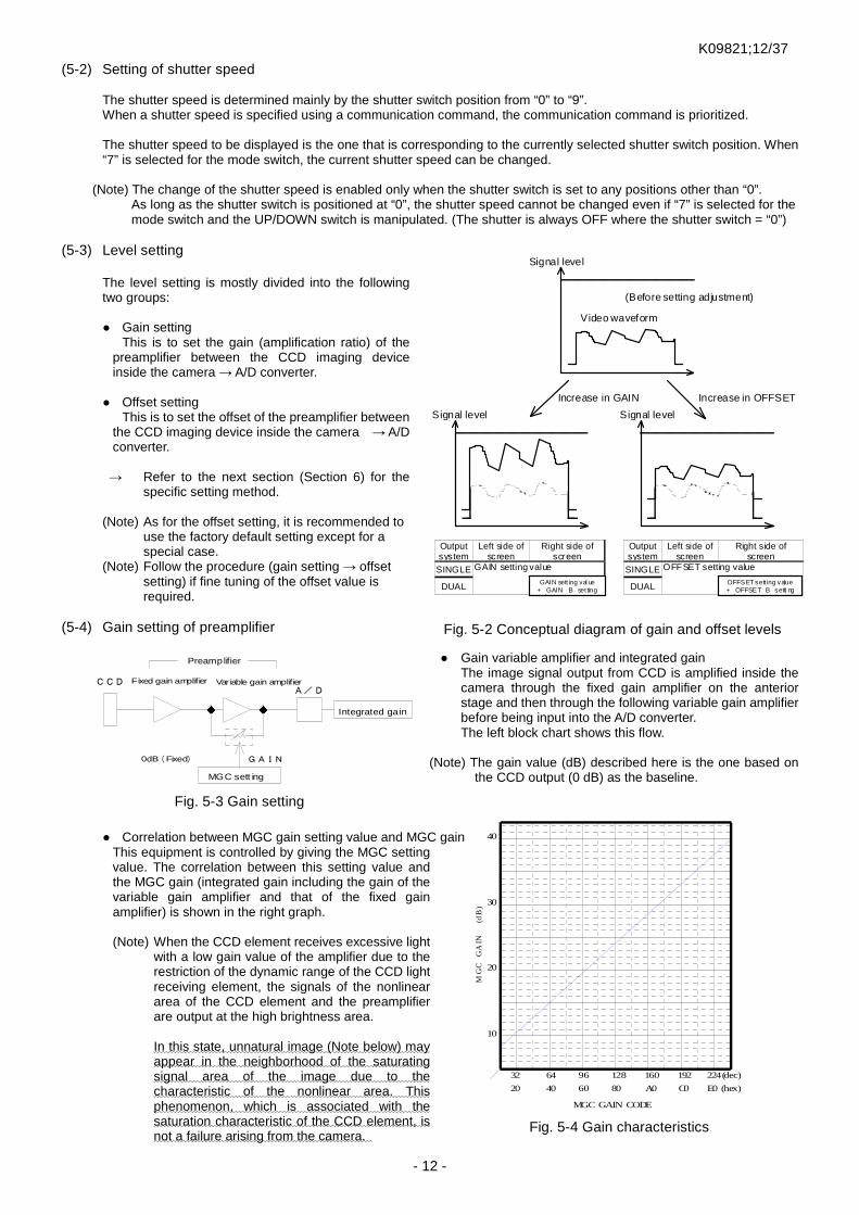
(5-3) Level setting
The level setting is mostly divided into the following two groups: Gain setting
This is to set the gain (amplification ratio) of the preamplifier between the CCD imaging device inside the camera → A/D converter.
Offset setting
This is to set the offset of the preamplifier between the CCD imaging device inside the camera → A/D converter.
→ Refer to the next section (Section 6) for the specific setting method.
(Note) As for the offset setting, it is recommended to
use the factory default setting except for a special case.
(Note) Follow the procedure (gain setting → offset setting) if fine tuning of the offset value is required.
(5-4) Gain setting of preamplifier
Gain variable amplifier and integrated gain
The image signal output from CCD is amplified inside the camera through the fixed gain amplifier on the anterior stage and then through the following variable gain amplifier before being input into the A/D converter. The left block chart shows this flow.
(Note) The gain value (dB) described here is the one based on
the CCD output (0 dB) as the baseline.
Correlation between MGC gain setting value and MGC gain
This equipment is controlled by giving the MGC setting value. The correlation between this setting value and the MGC gain (integrated gain including the gain of the variable gain amplifier and that of the fixed gain amplifier) is shown in the right graph. (Note) When the CCD element receives excessive light
with a low gain value of the amplifier due to the restriction of the dynamic range of the CCD light receiving element, the signals of the nonlinear area of the CCD element and the preamplifier are output at the high brightness area. In this state, unnatural image (Note below) may appear in the neighborhood of the saturating signal area of the image due to the characteristic of the nonlinear area. This phenomenon, which is associated with the saturation characteristic of the CCD element, is not a failure arising from the camera.
Signal level
Video waveform
(Before setting adjustment)
Increase in GAIN Increase in OFFSET
Signal level Signal level
Output system
Left side of screen
Right side of screen
Output system
Left side of screen
Right side of screen
SINGLE GAIN setting value SINGLE OFFSET setting value
DUAL DUAL
OFFSET sett ing value + OFFSET B setti ng value
GAI N sett ing val ue + GAIN B set ting value
CCD
Preamplifier
A/D
GAIN
Var iable gain amplifier
0dB(Fixed)
Integrated gain
MGC sett ing
Fixed gain amplifier
MGC GAIN CODE
MG
CG
AIN
(dB
)
10
20
30
40
20 40 60 80 A0 C0 E0 (hex)
32 64 96 128 160 192 224(dec)
Fig. 5-2 Conceptual diagram of gain and offset levels
Fig. 5-3 Gain setting
Fig. 5-4 Gain characteristics
K09821;13/37
- 13 -
Program page F
Program pages from B to E Program page A
[Electronic shutter operation mode] • Shutter system = Continuous/asynchronous • Type of shutter speed = High speed/ low speed • Electronic shutter table = Correspondence relation
b/w shutter switch position and shutter speed
[Other operation modes] • Scanning system = Normal /Partial
[Level setting] • Gain setting value = (Saved as the internal value) • Offset = (Saved as the internal value) And others
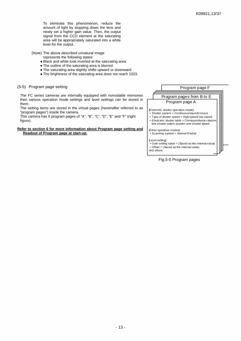
Fig.5-5 Program pages
To eliminate this phenomenon, reduce the amount of light by stopping down the lens and newly set a higher gain value. Then, the output signal from the CCD element at the saturating area will be appropriately saturated into a white level for the output.
(Note) The above described unnatural image
represents the following states: Black and white look inverted at the saturating area. The outline of the saturating area is blurred. The saturating area slightly shifts upward or downward. The brightness of the saturating area does not reach 1023.
(5-5) Program page setting
The FC series cameras are internally equipped with nonvolatile memories then various operation mode settings and level settings can be stored in them. The setting items are stored in the virtual pages (hereinafter referred to as “program pages”) inside the camera. This camera has 6 program pages of “A”, “B”, “C”, “D”, “E” and “F” (right figure).
Refer to section 6 for more information about Program page setting and Readout of Program page at start-up.
K09821;14/37
- 14 -
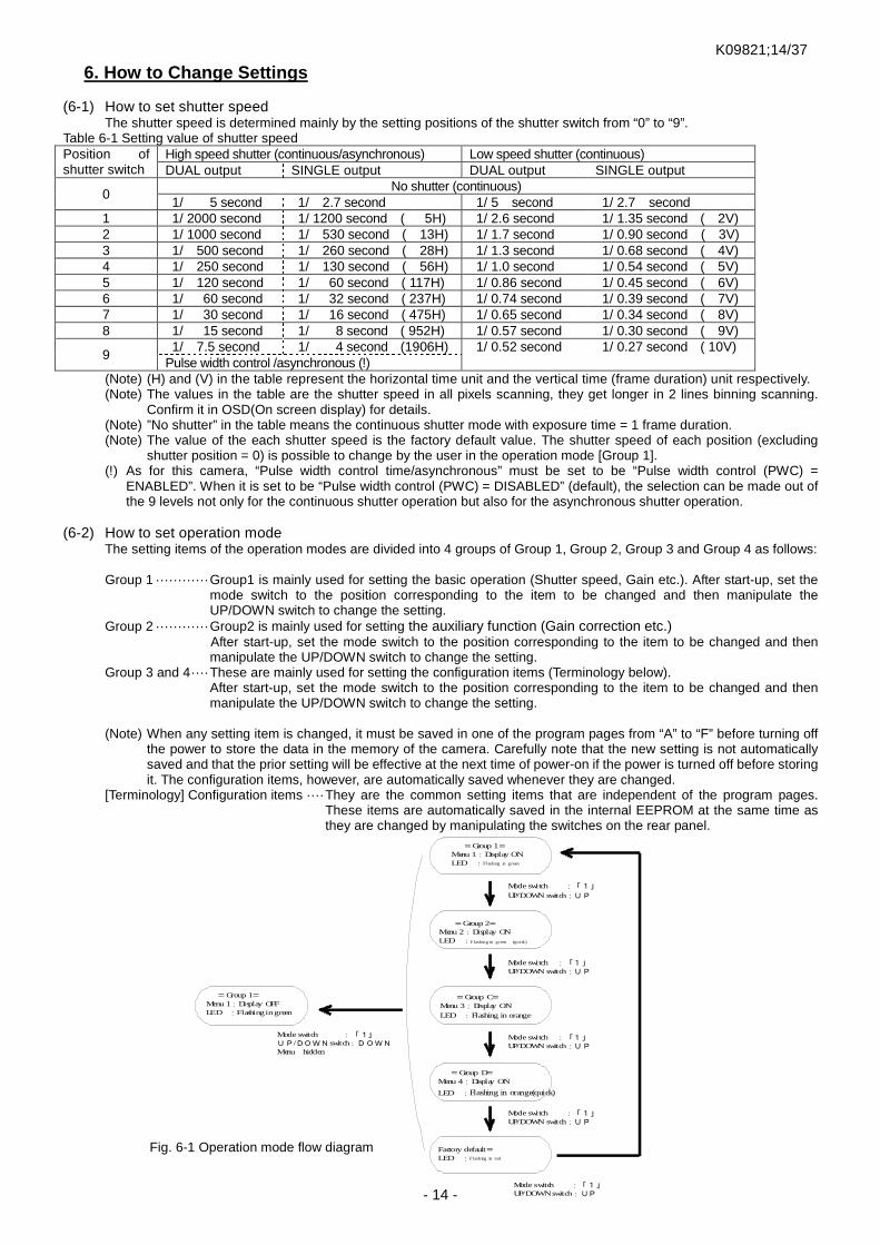
6. How to Change Settings (6-1) How to set shutter speed
The shutter speed is determined mainly by the setting positions of the shutter switch from “0” to “9”. Table 6-1 Setting value of shutter speed Position of shutter switch
High speed shutter (continuous/asynchronous) Low speed shutter (continuous) DUAL output SINGLE output DUAL output SINGLE output
0 No shutter (continuous)
1/ 5 second 1/ 2.7 second 1/ 5 second 1/ 2.7 second 1 1/ 2000 second 1/ 1200 second ( 5H) 1/ 2.6 second 1/ 1.35 second ( 2V) 2 1/ 1000 second 1/ 530 second ( 13H) 1/ 1.7 second 1/ 0.90 second ( 3V) 3 1/ 500 second 1/ 260 second ( 28H) 1/ 1.3 second 1/ 0.68 second ( 4V) 4 1/ 250 second 1/ 130 second ( 56H) 1/ 1.0 second 1/ 0.54 second ( 5V) 5 1/ 120 second 1/ 60 second ( 117H) 1/ 0.86 second 1/ 0.45 second ( 6V) 6 1/ 60 second 1/ 32 second ( 237H) 1/ 0.74 second 1/ 0.39 second ( 7V) 7 1/ 30 second 1/ 16 second ( 475H) 1/ 0.65 second 1/ 0.34 second ( 8V) 8 1/ 15 second 1/ 8 second ( 952H) 1/ 0.57 second 1/ 0.30 second ( 9V)
9 1/ 7.5 second 1/ 4 second (1906H) 1/ 0.52 second 1/ 0.27 second ( 10V) Pulse width control /asynchronous (!)
(Note) (H) and (V) in the table represent the horizontal time unit and the vertical time (frame duration) unit respectively. (Note) The values in the table are the shutter speed in all pixels scanning, they get longer in 2 lines binning scanning.
Confirm it in OSD(On screen display) for details. (Note) ”No shutter” in the table means the continuous shutter mode with exposure time = 1 frame duration. (Note) The value of the each shutter speed is the factory default value. The shutter speed of each position (excluding
shutter position = 0) is possible to change by the user in the operation mode [Group 1]. (!) As for this camera, “Pulse width control time/asynchronous” must be set to be “Pulse width control (PWC) =
ENABLED”. When it is set to be “Pulse width control (PWC) = DISABLED” (default), the selection can be made out of the 9 levels not only for the continuous shutter operation but also for the asynchronous shutter operation.
(6-2) How to set operation mode
The setting items of the operation modes are divided into 4 groups of Group 1, Group 2, Group 3 and Group 4 as follows: Group 1 ············ Group1 is mainly used for setting the basic operation (Shutter speed, Gain etc.). After start-up, set the
mode switch to the position corresponding to the item to be changed and then manipulate the UP/DOWN switch to change the setting.
Group 2 ············ Group2 is mainly used for setting the auxiliary function (Gain correction etc.) After start-up, set the mode switch to the position corresponding to the item to be changed and then
manipulate the UP/DOWN switch to change the setting. Group 3 and 4 ···· These are mainly used for setting the configuration items (Terminology below).
After start-up, set the mode switch to the position corresponding to the item to be changed and then manipulate the UP/DOWN switch to change the setting.
(Note) When any setting item is changed, it must be saved in one of the program pages from “A” to “F” before turning off
the power to store the data in the memory of the camera. Carefully note that the new setting is not automatically saved and that the prior setting will be effective at the next time of power-on if the power is turned off before storing it. The configuration items, however, are automatically saved whenever they are changed.
[Terminology] Configuration items ···· They are the common setting items that are independent of the program pages. These items are automatically saved in the internal EEPROM at the same time as they are changed by manipulating the switches on the rear panel.
Fig. 6-1 Operation mode flow diagram
=Group 1=Menu 1:Display OFFLED :Flashingingreen
=Group 1=Menu 1:Display ONLED :Fl ashing in green
Mode switch :「1」
UP/DOWN switch:UP
=Group 2=Menu 2:Display ONLED :Flashing in green (q uick)
=Group C=Menu 3:Display ONLED :Flashing in orange
=Group D=Menu 4:Display ON
LED :Flashing in orange(quick)
Factory default=LED :Fl ashing in red
Mode switch :「1」UP/DOWNswitch:DOWNMenu hidden
Mode switch :「1」UP/DOWN switch:UP
Mode switch :「1」UP/DOWN switch:UP
Mode switch :「1」UP/DOWN switch:UP
Mode switch :「1」UP/DOWNswitch:UP

K09821;15/37
- 15 -
Table 6-2 Setting manipulation for Operation Mode Setting [Group 1] Position of
mode switch Item to be changed UP/DOWN switch
UP position DOWN position 0 Change of gain Increase in gain Decrease in gain 1 Menu display (MENU) <* C> ON OFF 2 Selection of preset 1 or 2 Preset 2 (+19db) Preset 1 (+16db) 3 Selection of preset 3 or 4 Preset 4 (+25db) Preset 3 (+22db) 4 All pixels・Double speed scanning mode(SCAN / front) All pixels (NORMAL) Double speed (DOUBLE) 5 Shutter – continuous/asynchronous (S.FORM / front) Continuous(NORMAL) Asynchronous(ASYNC) 6 Shutter – high speed/low speed (S.TIME / rear) High speed (HIGH) Low speed (LOW) 7 Change of shutter speed (S.TIME / front) Shorter Longer 8 Digital offset (OFFSET) Increase in offset Decrease in offset 9 Not used
A to F Program pages from A to F Write Readout (Note) Decibel value in “Selection of preset” is a rough value. (Note) The shutter speed can be changed only when the shutter switch is currently set at any other positions than “0”.
When the shutter switch is positioned at “0”, the shutter speed cannot be changed even if the mode switch is set to the position “7” and the UP/DOWN switch is manipulated. (The shutter is always OFF where shutter switch = “0”.)
Table 6-3 Setting manipulation for Operation Mode Setting [Group 2]
Position of mode switch Item to be changed
UP/DOWN switch UP position DOWN position
1 Menu display (MENU) <* C> ON OFF 2 to 3 Not used (-)
4 Enabled/disabled for pulse width control (PWC) (!) ENABLED DISABLED A to F Program pages from A to F Write Readout
(!) When the setting of “ Enabled/disabled for pulse width control” is not set to be “ENABLED”, the pulse width control is not effective even if the shutter switch is set to the position “9” for the asynchronous shutter operation. In this case, the preset shutter asynchronous shutter is effective.
Table 6-4 Setting manipulation for Operation Mode Setting [Group 3]
Position of mode switch Item to be changed
UP/DOWN switch UP position DOWN position
1 Menu display (MENU) <* C> ON OFF 2 Operation confirmation buzzer (BZ) <* C> ON OFF 3 Serial communication baud rate (BAUDP) <* C> 19200 bps 9600 bps
4 to 5 <Not used> (-) - - 6 Polarity setting for Vinit2 (Vinit2) <* C> Positive logic
(POSITIVE) Negative logic (NEGATIVE)
7 Strobe signal output (STRB0,1) <* C> Switching Switching Table 6-5 Setting manipulation for Operation Mode Setting [Group 4]
Position of mode switch Item to be changed
UP/DOWN switch UP position DOWN position
1 Menu display (MENU) <* C> ON OFF 2 Test pattern (PATTERN) <* C> ON OFF 3 Output bit (BIT) <* C> Increase in bit Decrease in bit 4 Output form (FORM) <* C> DUAL SINGLE 5 Enabled/disabled for automatic correction
(ATCR) <* C> ENABLED DISABLED
6 <Not used> (-) - - 7 Vsub voltage (VSUB) <* C> Increase in voltage Decrease in voltage
[Explanation] Vsub voltage Vsub voltage is the bias voltage (substrate voltage) that serves to control the blooming effect (resulting in blur or running image at a saturating area) that arises from excessive light getting into CCD. If a high Vsub voltage is set, the blooming effect can be reduced, although an excessively high voltage leads to a narrower operation range of CCD because it is associated with a decrease in the saturating voltage of the CCD output. It is appropriately set before shipment because the optimum Vsub voltage varies by CCD.
* Notes in common with all setting groups (Note) The standard factory mode (default) is underlined. (Note) The default value of output bit is 8 bit. It is changed to 10 bit at first UP operation and 12 bit at second UP operation. (Note) The default value of strobe signal output is OFF. It is changed to exposure timing signal at first UP operation and
busy signal at second UP operation. (Note) The items marked with <* C> in the table (configuration items) are automatically stored in EEPROM whenever they
are changed. (Note) The new settings of the other items than the configuration items are lost at the time of power-off unless they are
manually saved in the program pages after changing them.

K09821;16/37
- 16 -
(6-3) Setting method of program page
The setting operations for the program pages are roughly divided into 2 groups: save (writing the current setting into the program page) and load (reading out the setting that was previously saved in the program page as the current setting). More specifically, “save” means copying the new setting that was changed from the current one on to one of the program pages after turning on the power while “load” means the opposite operation that is reading out the setting saved one of the program pages as the current setting.
The camera operates in accordance with the current setting that was read out to RAM. Program page F
Program pages from B to E
Program page A
[Electronic shutter operation mode] • Shutter mode = Continuous/asynchronous • Type of shutter speed = High speed/low speed • Electronic shutter table = Correspondence
relation between shutter switch position and shutter speed
• Pulse width control = Enabled/disabled [Other operation modes]
• Scanning system = Normal/partial [Level setting]
• Gain setting value = (Saved as the internal value)
• Offset = (Saved as the internal value )
[Electronic shutter operation mod e] • Shutter mode = Continuous/asynchronous • Type of shutter speed = High speed/low speed • Electronic shutter table = Correspondence
relation between shutt er switch position and shutter speed
• Pulse width control = Enabled/disabled [Other operation modes]
• Scanning system = Normal/partial [Level setting]
• Gain setting value = (Saved as the internal value)
• Offset = (Saved as t he internal value)
Current settings Save
Load
Effective even after power-off Lost at power-off
Fig. 6-2 Conceptual diagram of saving and loading operations
[Explanation] Correlation between current setting and program page
The setting information saved in the program page is automatically read out to RAM (volatile memory) when the camera is turned on, and that determines the operation of the camera as the current setting. When the setting of a mode is changed, the older one is overwritten, and the new setting is temporarily effective as the operation setting for the camera until the power is turned off. The new setting in the program page on RAM, however, is lost when the power is turned off, and the old setting before power-on will be effective for the operation of the camera. Accordingly, it is absolutely necessary to write the new setting in one of the program pages from “A” to “F” to save it. The setting saved in the program page can be read out for use by the loading operation (including automatic load at power-on) as described later.
Automatic loading at power-on
When the power is turned on, the camera automatically loads the setting stored in one of the program page from “A” to “F”, which determined the operation of the camera. The program page of which setting is automatically loaded is determined by the position of the mode switch at the time of power-on.
(Note) Note that the setting of the program page “A” is automatically loaded when the switch is at any position other than “B” to “F”.
Manual load/save
Manual load/save of the setting from/to the program page can be enabled when setting the mode switch to one of the positions from “A” to “F” and manipulate the UP/DOWN switch after the power is turned on.
(Note) This saving operation must be performed to keep the new setting effective for later use after changing it.
Table 6-6 Automatically loaded
program page
Table 6-7 Setting operation for program page (manual operation)
Position of mode switch
Automatically loaded program page
Position of mode switch
Item to be changed
UP/DOWN switch UP position DOWN position
0 to A Program page A A Program page A
Save Load
B Program page B B Program page B C Program page C C Program page C D Program page D D Program page D E Program page E E Program page E F Program page F F Program page F

K09821;17/37
- 17 -
Camera type [V.X.XX]
Menu disp lay of Setting Group 1
MENU1 MENU : *ON GAIN : 120 / SET2 OFFSET : 160 S.TIME : OFF (190.3)ms S.FORM : ASYNC / HIGH SCAN : NORMAL
Tc= 30.0 deg MS=1 SS=0 MF=0000.0001
(6-4) Description of menu display by OSD (On Screen Display) This camera is equipped with the OSD function of imposing a text on the output digital image signal. Using this function, the current setting status of the camera can be displayed over the image of the capture board in menu form.
(Note) This camera is basically designed so that all settings can be done
without this menu display by OSD just like the conventional cameras of FC series. However the menu display allows the user to quickly understand the current settings at a glance. Furthermore, if the contents of the menu display are captured and saved before collecting data using the camera, they serve as useful information to be referred when comparing data or setting additionally introduced cameras.
[Requirement for menu display] The menu display requires a system that is capable of updating the captured image constantly responding to the timing of FDV/LDV to be output from the camera on the side of the user‘s capture board. When the asynchronous shutter mode is set for the camera, the repetitive asynchronous shutter operations are automatically made at certain intervals to automatically refresh the image so that the menu display is updated. During this process, the externally input trigger signals are ignored. The display area of OSD is located on the upper left on the entire area of the captured image, and therefore this system must be additionally capable of displaying this menu on the screen. [ON/OFF of menu display] If the OSD menu display does not appear on the capture image, perform the following procedure to display it: Turn on the power in the normal manner → Set the mode switch to “1” → Apply an upward stroke to the UP/DOWN switch To disable the output of the menu display, perform the same procedure except for applying a downward stroke to the switch. (Note) Since the ON/OFF setting of the menu display is a configuration item, it is automatically saved in the internal
EEPROM. (Note) If the menu display is set to be ON in the asynchronous shutter mode, the repetitive trigger (cyclic trigger) that is
generated inside the camera is automatically input. Make sure to set the menu display to OFF when the camera is used in the normal state (online state).
(Note) Note that the difference between the pulse width generated by the camera with the menu display turned on and that provided by the actual user unit results in the difference in the brightness of image between those, when the asynchronous shutter operation in the pulse width control mode is set (S.FORM=ASYNC/HIGH, PWC=ENABLED).
[Description of display content] MENU 1, 2, 3 or 4: Current setting is displayed. The following is displayed: ”1”: Setting content of Setting Group 1 ”2”: Setting content of Setting Group 2 ”3”: Setting content of Setting Group 3 ”4”: Setting content of Setting Group 4 MENU: Current menu status is displayed.
When the menu is being displayed, “ON” is kept displayed. When “(CYCLIC)” is displayed on the right, the camera is cyclically outputting the asynchronous shutter image using the internal trigger to refresh the image. When the asynchronous shutter mode is set and the menu is set to ON, the cyclic trigger input is automatically selected. When the menu is set to OFF, the cyclic trigger input is automatically cancelled and external trigger is ready to be received.
MENU1 GAIN: The left number is the gain setting value expressed in the decimal system.
When gain and offset set value coincides with preset value (four levels of preset value), “SET” followed by corresponding preset No. is displayed on the right side.
OFFSET: The setting value of the digital signal offset is displayed in the
decimal system. S.TIME: The current shutter exposure time is displayed. The left number is
H number (horizontal synchronous time unit, in the case of high speed shutter – range: 1 to number of horizontal lines in decimal system) or V number (vertical synchronous time unit, in the case of low speed shutter – range: 1 to 50 in decimal system). The right number in parentheses shows the actual time. The actual time is displayed after being converted in accordance with the settings of the scan mode (all pixels/partial) and shutter mode (HIGH/LOW).
OSD display area
Entire area of captured image
Display position by OSD
K09821;18/37
- 18 -
MS=1 SS=7 MS=1 SS=7
ID: CAMERA-1 Camera type
ID not specified ID speci fied
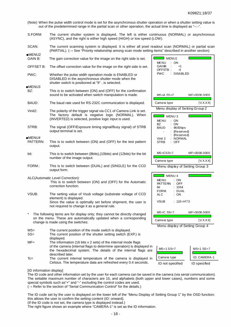
(Note) When the pulse width control mode is set for the asynchronous shutter operation or when a shutter setting value is
out of the predetermined range in the partial scan or other operation, the actual time is displayed as “--.-”. S.FORM: The current shutter system is displayed. The left is either continuous (NORMAL) or asynchronous
(ASYNC), and the right is either high speed (HIGH) or low speed (LOW). SCAN: The current scanning system is displayed. It is either all pixel readout scan (NORMAL) or partial scan
(PARTIAL). (→ See “Priority relationship among scan mode setting items” described in another section) MENU2 GAIN B: The gain correction value for the image on the right side is set. OFFSET B: The offset correction value for the image on the right side is set. PWC: Whether the pulse width operation mode is ENABLED or
DISABLED in the asynchronous shutter mode when the shutter switch is positioned at “9” , is selected.
MENU3 BZ: This is to switch between (ON) and (OFF) for the confirmation
sound to be activated when switch manipulation is made. BAUD: The baud rate used for RS-232C communication is displayed. Vinit2: The polarity of the trigger signal via CC1 of Camera Link is set.
The factory default is negative logic (NORMAL). When (INVERTED) is selected, positive logic input is used.
STRB: The signal (OFF/Exposure timing signal/Busy signal) of STRB
output terminal is set.
MENU4 PATTERN: This is to switch between (ON) and (OFF) for the test pattern
output. bit: This is to switch between (8bits),(10bits) and (12bits) for the bit
number of the image output. FORM.: This is to switch between (DUAL) and (SINGLE) for the CCD
output form. ALC(Automatic Level Correction): This is to switch between (ON) and (OFF) for the Automatic
correction function. VSUB: The setting value of Vsub voltage (substrate voltage of CCD
element) is displayed. Since the value is optimally set before shipment, the user is not required to change it as a general rule.
* The following items are for display only; they cannot be directly changed
on the menu. These are automatically updated when a corresponding change is made using the switches:
MS= The current position of the mode switch is displayed. SS= The current position of the shutter setting switch (EXP.) is
displayed. MF= The information (16 bits x 2 sets) of the internal mode flags
of the camera (internal flags to determine operation) is displayed in the hexadecimal system. The details of the internal flags are described later.
Tc= The current internal temperature of the camera is displayed in Celsius. The temperature data are refreshed every 0.4 seconds.
[ID information display] The ID code and other information set by the user for each camera can be saved in the camera (via serial communication). The settable maximum number of characters are 15, and alphabets (both upper and lower cases), numbers and some special symbols such as”+” and “-” excluding the control codes are used. (→ Refer to the section of “Serial Communication Control” for the details.) The ID code set by the user is displayed on the lower left of the “Menu Display of Setting Group 1” by the OSD function; this allows the user to confirm the setting content (ID: onward). (If the ID code is not set, the camera type is displayed instead.) The right figure shows an example where “CAMERA-1” is set as the ID information.
Camera type [V.X.XX]
Menu display of Setting Group 2
MENU2 MENU : ON GAINB : +1 OFFSTB : -4 PWC : DISABLED MS=A SS=7 MF=0008.0000
Camera type [V.X.XX]
Menu disp lay of Setting Group 3
MENU 3 MENU : ON BZ : ON BAUD : 9600bps
- : (Reserved) : (Reserved) Vinit 2 : NORMAL STRB : OFF MS=CSS=7 MF=0008.0000
Camera type [V.X.XX]
Menu disp lay of Setting Group 4
MENU 4 MENU : ON PATTERN : OFF bit : 10bit FORM. : DUAL ALC : ON
VSUB : 115=H'73 MS=C SS=7 MF=0008.0000

K09821;19/37
- 19 -
[Change of setting] Perform the procedure described in another section: “(6-3) How to set operation mode” when changing the current setting while referring to the information displayed by the OSD function. When the position of the mode switch is changed, a flashing “*” mark appears on the left of the numeric value or the parameter of the item corresponding to the switch position to indicate that the setting can be changed using the UP/DOWN switch. When a stroke is applied to the UP/DOWN switch, the value of gain or others increases or decreases by 1. When a stroke is applied and kept for 2 seconds, the number continuously increases or decreases at fast speed after the response sound of “pip-pip”. [Save of setting after change] The settings changed on the menu are divided into 2 groups; one is for those that are automatically saved in the nonvolatile ROM area whenever a change is made (configuration items) and the other is for those that are saved in the program pages only when manually stored (See the following table). Table 6-8
Automatic save and manual save Item Remark
Items automatically saved when changed on menu MENU, BZ, BAUD, Vinit2, STRB, PATTERN, BIT Reflected in (CR)
VSUB Saved as numerical value
Items requiring manual save into program pages after changed on menu
GAIN, OFFSET, S.TIME, GAINB, OFFSETB
Saved as numerical value
S.FORM, SCAN, PWC Reflected in (FR)
(Note) The value of “VSUB” is stored in an area independent of the program pages. (6-5) Internal flag register (FR) and configuration register (CR)
The camera internally has RAM areas for the flag register (FR) (2 bytes) and the configuration register (CR) (2 bytes). If the user checks the contents of these registers, he or she can get the information on the current operational status. In addition, it is possible to change more than one operation mode at a time by way of rewiring the contents of the registers. In this section, the functions of the flag register and the configuration resister are described. Flag register (FR) and configuration register (CF)
Both FR and CR are 2 bite (16 bit) memory areas in RAM. When the camera is turned on, the data stored in the internal EEPROM (nonvolatile storage) are read out and copied into these areas. The current operation mode of the camera is determined by the data in FR and CR. Each set of FR data is saved in each of the program pages (A to F), and the data are copied to the flag register by the automatic loading at the time of power-on or manual loading onto one of the program pages to determine the operation of the camera. On the contrary, the memory area for CR in EEPROM is only one and the data are read out independently of the program pages to determine the operation mode.
The data of those registers can be changed by manipulating the switches on the rear panel of the camera (regardless of ON/OFF state on the menu display) or using serial communication commands.
When the menu display is set to “ON”, the contents of (FR) and (CR) are displayed as 8 numbers like “MF=0000.0000” to show the current states of the registers. The numbers are expressed in the hexadecimal system. The first (upper) 2 bytes show the setting data of the configuration register (CR) and the bottom (lower) 2 bytes show the setting data of the flag register (FR).
Table 6-9 Description of CR data Bit Abbrev. Content Logic Remark 0 MNI Disabled display of menu screen 1: Disabled (OFF) 1 BZI Disabled buzzer output 1: Disabled (OFF) 2 TPEN ON/OFF selection for test pattern 1: Test pattern ON 3 DFRM0
Selection of output data format 01: 8bit 00:10bi 10:12bit 11: not used
4 DFRM1 5 STRB0
Selection of output form on Strobe signal terminal 00:OFF 01:STRB 10:BUSY 11: (timer)
OFF: always H level output 6 STRB1
7 CC1P Selection of trigger signal (Vinit2) polarity via CC1 1: Positive polarity 8 - (Not used)
*1 9 BAUD 9600bps/19200bps selection for serial communication speed 1=19200bps
10 - (Not used) 11 - (Not used) 12 ALC Enabled for light and left automatic correction 1: Enabled 13 CCD01 (Not used) 14 CCD00 CCD output mode 1: SINGLE output 15 DEFR Request for reading out default at next start-up 1: Request *1
(Note) CR(3) is “1”and the other of CR data are “0” as factory default. *1: Can not be changed by a communication command.
K09821;20/37
- 20 -
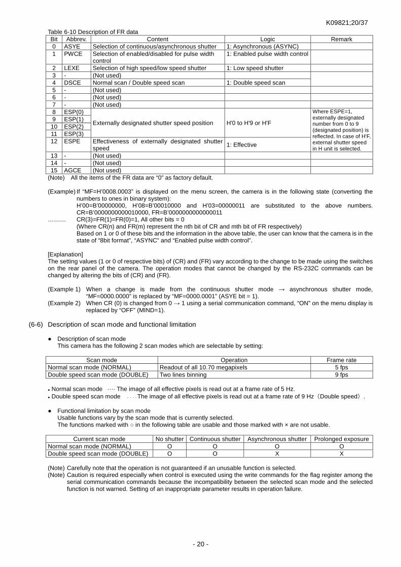
Table 6-10 Description of FR data Bit Abbrev. Content Logic Remark 0 ASYE Selection of continuous/asynchronous shutter 1: Asynchronous (ASYNC) 1 PWCE Selection of enabled/disabled for pulse width
control 1: Enabled pulse width control
2 LEXE Selection of high speed/low speed shutter 1: Low speed shutter 3 - (Not used) 4 DSCE Normal scan / Double speed scan 1: Double speed scan 5 - (Not used) 6 - (Not used) 7 - (Not used) 8 ESP(0)
Externally designated shutter speed position H'0 to H'9 or H'F
Where ESPE=1, externally designated number from 0 to 9 (designated position) is reflected. In case of H'F, external shutter speed in H unit is selected.
9 ESP(1) 10 ESP(2) 11 ESP(3) 12 ESPE Effectiveness of externally designated shutter
speed 1: Effective
13 - (Not used) 14 - (Not used) 15 AGCE (Not used)
(Note) All the items of the FR data are “0” as factory default. (Example) If “MF=H’0008.0003” is displayed on the menu screen, the camera is in the following state (converting the
numbers to ones in binary system): H’00=B’00000000, H’08=B’00010000 and H’03=00000011 are substituted to the above numbers. CR=B’0000000000010000, FR=B’0000000000000011
……… CR(3)=FR(1)=FR(0)=1, All other bits = 0 (Where CR(n) and FR(m) represent the nth bit of CR and mth bit of FR respectively) Based on 1 or 0 of these bits and the information in the above table, the user can know that the camera is in the state of “8bit format”, “ASYNC” and “Enabled pulse width control”.
[Explanation] The setting values (1 or 0 of respective bits) of (CR) and (FR) vary according to the change to be made using the switches on the rear panel of the camera. The operation modes that cannot be changed by the RS-232C commands can be changed by altering the bits of (CR) and (FR).
(Example 1) When a change is made from the continuous shutter mode → asynchronous shutter mode,
“MF=0000.0000” is replaced by “MF=0000.0001” (ASYE bit = 1). (Example 2) When CR (0) is changed from 0 → 1 using a serial communication command, “ON” on the menu display is
replaced by “OFF” (MIND=1). (6-6) Description of scan mode and functional limitation
Description of scan mode This camera has the following 2 scan modes which are selectable by setting:
Scan mode Operation Frame rate
Normal scan mode (NORMAL) Readout of all 10.70 megapixels 5 fps Double speed scan mode (DOUBLE) Two lines binning 9 fps
Normal scan mode ···· The image of all effective pixels is read out at a frame rate of 5 Hz. Double speed scan mode ・・・・The image of all effective pixels is read out at a frame rate of 9 Hz(Double speed).
Functional limitation by scan mode Usable functions vary by the scan mode that is currently selected.
The functions marked with in the following table are usable and those marked with × are not usable.
Current scan mode No shutter Continuous shutter Asynchronous shutter Prolonged exposure Normal scan mode (NORMAL) O O O O Double speed scan mode (DOUBLE) O O X X
(Note) Carefully note that the operation is not guaranteed if an unusable function is selected. (Note) Caution is required especially when control is executed using the write commands for the flag register among the
serial communication commands because the incompatibility between the selected scan mode and the selected function is not warned. Setting of an inappropriate parameter results in operation failure.

K09821;21/37
- 21 -
(6-7) Typical setting procedure (Example 1) This is the procedure for setting the gain for the
asynchronous shutter operation (1/250 sec.). [Explanation] The left example of the setting procedure is for using the camera in the asynchronous shutter operation. In the left example, the operation mode is temporarily set to be the continuous shutter operation because this makes it easier to set the gain and others. In the case where the image output state can be easily checked by way of repeatedly inputting external trigger signal (Vinit) from a user device, the operation mode should be set to be “Asynchronous Shutter” from the beginning before setting the gain and others. (Note) When the pulse width control mode is set for the
asynchronous shutter operation, the above described method in which the continuous shutter mode is temporarily set cannot be used (because the shutter speed at the position “9” for the asynchronous shutter mode is different from that for the continuous shutter mode). If the camera is used in the pulse width control mode, it is necessary to set the asynchronous shutter operation and then set the gain and others while actually inputting the trigger signal (Vinit) from a user device.
(!) This equipment is designed so that the pulse width
control mode can be set to OFF even when it is in the asynchronous shutter mode and the mode switch is at the position “9”. (Default condition)
(Note) This equipment is put into the condition where the cyclic asynchronous shutter trigger is internally generated (in the
cyclic trigger state) when the menu is displayed. Therefore, when the menu is displayed, it is not necessary to temporarily switch to the continuous shutter operation as shown above.
(6-8) Read out of factory default
Setting items to be read out to RAM [Electronic shutter operation mode]
• Shutter mode = Continuous • Type of shutter speed = High speed • Electronic shutter table = Content of (Table 6-1) • Pulse width control = DISABLED
[Other operation modes] • Scanning system = Normal scan
[Level setting] • Gain setting value = (Factory default) • Offset setting value = (Factory default)
[Configuration] • Manu display = ON • BZ = ON • Baud rate = 9600bps • Vinit2 polarity = NORMAL (negative logic) • Test pattern = OFF • Continuous strobe signal =OFF • Vsub voltage = (Factory default)
This procedure is for reading out the factory default in order to initialize the setting that was changed by the user after purchase. With this equipment, the following 2 different procedures are selectable for the readout: a. The factory default is retrieved onto the internal RAM of the
camera. b. The factory default is retrieved onto the internal RAM of the
camera and written into the all program pages. (Note) When the procedure a. is selected, the “storage page for
factory default” that is located separately from the memory for automatic loading at the time of power-on (program pages from “A” to “F”) is loaded and the camera is started up. In this case, the data is just read out to the internal RAM of the camera. If it is necessary to use the camera with the factory default values after the power is turned off, those must be saved in the program pages from “A” to “F”. When the procedure b. is selected, the parameters that were read out are automatically saved in the program pages from “A” to “F”. Carefully note that the earlier setting data that were saved by the user are all overwritten and lost.
Fig. 6-4 Setting contents immediately after reading out factory default
[Procedure a. (to retrieve default onto RAM)] <Step 1> Set the mode switch to the position “9”, and manipulate the UP/DOWN switch either upward or downward.
Then, turn on the power and keep the position of the UP/DOWN switch for several seconds. <Step 2> Return the UP/DOWN switch to the neutral position when the response sound of “pip-pip” is heard and
LED flashes in orange. <Step 3> For execution, apply an upward or downward stroke to the UP/DOWN switch once again. For cancellation,
turn off the power to the camera. <Step 4> The camera automatically restarts and the operation mode is set to be Group 1. (Note) To save the read data, set the mode switch to “A” (or other page corresponding to the data to be saved) and apply
an upward stroke to the UP/DOWN switch (save to the program page).
Save setting in program page A.
Be ready for saving in program page.
Switch to asynchronous shutter operation.
Be ready for switching between continuous shutter operation and asynchronous shutter operation.
Set gain while checking image.
Be ready for changing gain.
Set shutter speed to 1/250 sec.
Temporarily switch to continuous shutter operation
Be ready for switching between continuous shutter operation and asynchronous shutter operation.
Turn on power.
Set mode switch to “5”.
Apply upward stroke to UP/DOWN switch.
Set shutter switch to “4”.
Set mode switch to “0”.
Set gain by manipulating UP/DOWN switch upward or downward.
Change mode switch to “5”.
Apply downward stroke to UP/DOWN switch.
Set mode switch to “A”.
Apply upward stroke to UP/DOWN switch.
Turn off power.
END
START
Fig. 6-3 Example of procedure for gain setting for asynchronous shutter

K09821;22/37
- 22 -
[Procedure b. (to retrieve default onto RAM and save it into all program pages)] <Step 1> Set the mode switch to the position “9”, and manipulate the UP/DOWN switch either upward or downward.
Then, turn on the power and keep the position of the UP/DOWN switch for several seconds. <Step 2> Return the UP/DOWN switch to the neutral position when the response sound of “pip-pip” is heard and
LED flashes in orange. <Step 3> Then, change the position of the mode switch to “0”. LED will flash in red. <Step 4> For execution, apply an upward or downward stroke to the UP/DOWN switch once again. For cancellation,
turn off the power to the camera. <Step 5> The camera restarts and the operation mode is set to be Group 1.
7. Serial Communication Command This camera can be externally controlled by the serial interface via Ethernet. (Note) When the operation modes of the camera are changed by the communication functions, it takes some time to switch the
modes. Carefully note that normal image may not be obtained from the signal for one frame each before and after transmitting a command.
(Note) The settings and timings of the serial communication commands are the same as those of the products that have the conventional RS-232C communication functions (e.g. FC2000CL).
The setting of the serial communication is as follows:
Baud rate : 9600bps or 19200bps(designated in Setting Group 2, Default is 9600bps.) Data : 8bit / character Stop bit : 1stop bit Parity : Non XON/XOFF : no control
Serial communication commands
The command packet starts with STX(02h), followed by command code(s) and command option parameter(s) and ends with ETX(03h). All those are of 8 bit ASCII codes. When the camera receives 1 packet (by detecting ETX:03h) and judges it is a normal packet, it returns a transaction completion signal (ACK: 06h) or others corresponding to the commands received. When the camera judges it is an abnormal packet, it returns the abnormal signal (NAK: 15h).
Operation mode “Group 1 to 4” and reception of serial communication commands
Serial communication commands are received only for the period when the camera is in the operation mode of “Group 1” (= “normal power-on state”). However, only the command “ARESET” (restoring to power-on state) is received even during the periods when the camera is in the operation modes of Group 2 to 4.
Description of each command
(1) Command “e”
Function: Initialization of page memory Transmission from host: STX: “e”: ETX Return by camera: STX: ACK: ETX (transaction completion), or STX: NAK: ETX (transaction rejection) * CPU initializes each of the page memories when the power is turned on next time. “Initialization” here means restoring
the parameter values stored in the internal EEPROM of the camera to the factory default values.
(2) Command “R” Function: Command for reporting camera operating state and setting status The contents of the report can be selected by adding the following option code after the command code “R”.
G: Gain report V: Camera version report T: Shutter SW set report S: Shutter report
(3) Gain report Transmission from host: STX: “R”: “G”: ETX Return by camera: STX: ACK: “R”: MGC set value: (AGC set value): (VRT set value):
(VRB set value): OFFSET set value: ETX (!) FC/FS11000GE does not use the values in parentheses. This camera returns the fixed values instead.

K09821;23/37
- 23 -
(4) Camera version report Transmission from host: STX: “R”: “V”: ETX Return by camera: STX: ACK: “R”:“Takenaka SYS.FC11000GE V1.00”: ETX
*The underlined values show the control program version number of the camera and a file name. These values and the number of characters vary by program version. Use it when confirming the communication mode of the camera and obtaining internal information of the camera. The maximum number of the characters to be inserted between ACK and ETX is 48.
(5) Shutter SW report
Transmission from host: STX: “R”: “T”: “H”: ETX Return by camera: STX: ACK: “R”: “H”:SW0: SW1: SW2: SW3: SW4: SW5: SW6: SW7: SW8: SW9: ETX
(6) Shutter mode report
Transmission from host: STX: “R”: “S”: ETX
Return by camera: STX: ACK: “R”: “”: “”: “”: Exposure time: ETX *1 *2 *3 *4
*1 to 3 Refer to (8) command “S” *4 : Exposure time
In the case where the electronic shutter exposure time is externally set: When the exposure time is set in the unit of H (horizontal scan time), the exposure setting count value of the time in H is returned. Example) If the shutter exposure time is 16Hs “0010”
In the case where the exposure time is set by the shutter switch number on the connector panel: Example) If the shutter switch is set to “4”: “I4..”
In the case where the exposure time is set by the shutter switch number via a serial communication command: Example) If “3” is specified for the shutter switch, : “S3..”
(7) Command “G”
Function: Command for setting gain Transmission from host: STX: “G”: MGC set value: (AGC set value): (VRT set value): (VRB set value): OFFSET set value:
ETX Return by camera: STX: ACK: ETX (transaction completion) or STX: NAK: ETX (transaction rejection) (!) This camera does not use the values in parentheses “ . ” must be transmitted to the camera.
2 digit ASCII codes in the hexadecimal system “20”~”E0”(32 to 224; decimal) are used for the data setting values of MGC and OFFSET. Example) If level 128 (decimal) is set: “80”
If level 200 (decimal) is set: “C8” The setting value that does not need a change should be represented by “.” (a full stop) so that the setting value before the command transmission is retained. Example) if only MGC is changed to Level 90 (decimal):
STX: “G”: “5A”: “.”: “.”: “.”: “.”: ETX
(8) Command “S” Function: Command for setting shutter mode and shutter exposure time Transmission from host: STX: “S”: “A” or “M”: “H” or “L”: “N” or “D”: exposure time: ETX Return by camera: STX: ACK: ETX (transaction completion), or STX: NAK: ETX (transaction rejection) The transmitting command has the following meanings: STX: “S”: “A” or “M”: “H” or “L”: “N” or “D”: Exposure time: ETX
*1 *2 *3 *4 *1 A: Asynchronous shutter M: Continuous shutter *2 H: High speed shutter L: Low speed shutter *3 N: Normal scan D: Double speed scan *4: Exposure time
The format of “Exposure time” complies with one of the followings: a. 4 characters corresponding to the hexadecimal which represents 2-byte number b. 4 characters of “S” “0 to 9” “..” for externally specifying a shutter position (2 full stops of “.” in the last are
mandatory.) In the case where the electronic shutter exposure time is externally set:
When the exposure time is set in the unit of H (horizontal scan time), the exposure setting count value of the time in H is set. Example) If the shutter exposure time is 16Hs: STX: “S”: “.”: “.”: “.”: “0010”: ETX

K09821;24/37
- 24 -
In the case where the exposure time is set by the shutter SW number on the connector panel: Example) If the shutter SW is set to “4”: STX: “S”: “.”: “.”: “.”: “S4..”: ETX
In the case where the exposure time is set to 3Hs in the asynchronous/high speed shutter mode: STX: “S”: “A”: “H”: “.”: “0003”: ETX
In the case where the control is returned to the setting by the shutter switch on the rear panel.: STX: “S”: “.”: “.”: “.”: “0000”: ETX
(Note) In the case where the exposure time is externally set using S command, the exposure time is locked finally to the
position designated by S command or directly designated value. The locked state is released by setting the exposure time to “0000” using RS-232C as described above. To release the locked state without the use of RS-232C after setting the exposure time by RS232C, execute “Read-out of Factory Default” operation
(Note) The allowable range of number is as follows when in directly setting the exposure time. The operation out of the range is not guaranteed.
Normal scan : H’0000 to H’087B (D’ 0 to 2171) (where “0” is used only when cancelling the external time setting ) Double speed scan: H’0000 to H’0551 (D’ 0 to 1361) (where “0” is used only when cancelling the external time setting )
(9) Command “E” Function: Command for editing shutter menu Transmission from host: STX: “E”: “H” : SW0: SW1: SW2: SW3: SW4: SW5: SW6: SW7: SW8: SW9: ETX Return by camera: STX: ACK: ETX (transaction completion), or STX: NAK: ETX (transaction rejection) ※ The exposure time (H) to be allocated to the shutter SW number is expressed in 4 digits in the hexadecimal system for
SW0 to SW9. ※ The exposure time for SW0 can not be changed. Example) If only the exposure time of SW5 for the high speed shutter operation is changed to 88 (decimal):
STX: “E”: “H”: “.”: “.”: “.”: “.”: “.” : “0058”: “.”: “.”: “.”: “.”: ETX
(10) Command “W”
Function: Command for saving operation mode (Write into page memory) Transmission from host: STX: “W”: memory page (“A” to “F”): ETX Return by camera: STX: ACK: ETX (transaction completion), or STX: NAK: ETX (transaction rejection) The current setting can be written and saved in the EEPROM of the specified page number.
(11) Command “L” Function: Command for reading out operation mode (Load) Transmission from host: STX: “L”: reading page (“A” to “H”): ETX Return by camera : STX: ACK: ETX (transaction completion), or STX: NAK: ETX (transaction rejection) * The factory default is stored in the Page H, which will be used when restoring to the default setting.
(12) Command “WMC” Function: Command for writing in configuration flag register (CR) (Write Mode Configuration) Transmission from host: STX: “WMC”: flag set value: ETX Return by camera: STX: ACK: ETX (transaction completion), or STX: NAK: ETX (transaction rejection) The content of “flag set value” (2 bytes/4 characters) can be written in the configuration register. (Note) This command does not execute the writing in EEPROM, and the setting by this command is lost when the power
is turned off. To save the setting value in EEPROM, use another command, “SMC”.
(13) Command “WMF” Function: Command for writing in mode flag register (FR) (Write Mode Flag) Transmission from host: STX: “WMF”: flag set value: ETX Return by camera : STX: ACK: ETX (transaction completion) or STX: NAK: ETX (transaction rejection) The content of “flag set value” (2 bytes/4 characters) can be written in the flag register. (Note) This command does not execute the writing in EEPROM, and the setting by this command is lost when the power
is turned off. To save the set value in EEPROM, use other commands, “WA to WF”, to save in the specified pages.
(14) Command “RMC” Function: Command for reading configuration flag register (CR) (Read Mode Configuration) Transmission from host: STX: “RMC”: ETX Return by camera: STX: ACK: “RMC”: flag set value: ETX (transaction completion), or STX: NAK: ETX (transaction
rejection)
K09821;25/37
- 25 -
The current content of the common mode flag register (2 bytes/4 characters) can be returned in the hexadecimal system. (15) Command “RMF”
Function: Command for reading mode flag register (FR) (Read Mode Flag) Transmission from host: STX: “RMF”: ETX Return by camera: STX: ACK: “RMF”: flag set value: ETX (transaction completion), or STX: NAK: ETX (transaction
rejection) The current content of the mode flag register (2 bytes/4 characters) can be returned in the hexadecimal system.
(16) Command “SMC” Function: Command for saving configuration flag register (CR) (Save Mode Configuration) Transmission from host: STX: “SMC”: ETX Return by camera: STX: ACK: ETX (transaction completion), or STX: NAK: ETX (transaction rejection) The current content of the common mode flag register can be saved in EEPROM.
(17) Command “RTMP” Function: Command for reading data of internal temperature of camera (Read TeMPerature) Transmission from host: STX: “RTMP”: ETX Return by camera: STX: ACK: “RTMP”: internal temperature data: ETX (transaction completion), or STX: NAK: ETX
(transaction rejection) The current content of the internal temperature data of the camera can be returned in the hexadecimal system. The effective data is the low 10 bits out of the returned 16 bits. This 10 bit value presents a signed integer value in two’s complement form -511 to 511. Actual temperature in Celsius is calculated by multiplying the value by a certain factor. → Refer to “(4-6) Monitoring function for internal temperature of camera” for the conversion method from the returned
data to temperature value.
(18) Command “X” Function: Command for generating asynchronous shutter trigger (eXecute Trigger) Transmission from host: STX: “X”: ETX Return by camera: STX: ACK: ETX (transaction completion), or STX: NAK: ETX (transaction rejection) When the camera is set to be in the asynchronous shutter mode (except in the time when the menu is being displayed), this command enables the camera to update the image by internally generating the asynchronous trigger signal. The internally generated trigger signal is of negative logic in 100ms±5%. The minimum value of repetitive pitch in asynchronous shutter operation using this command is 300ms. Only in the case of trigger signal by this command, the buzzer inside the camera sounds for one shot (aprrox. 50ms) in response to trigger signal input. If the buzzer is not required to sound , make “Operation confirmation buzzer = OFF” changing the configuration flag by the configuration menu setting or serial communication command. (Note) When the command “X” is received, “ACK”(transaction completion) is returned even if the asynchronous shutter
mode is not selected or the menu is displayed (in the setting condition where the asynchronous shutter operation is disabled by the command “X”).
(Note) Since the command is executed through the serial communication, it does not quickly act unlike the normal trigger signal. Therefore, it is recommended to use the commands only when no immediacy is required, for example, in the case where the operation of the camera is checked for setting, or the moving velocity of an object to be shot is extraordinary slow.
(19) Command “ARESET”
Function: Command for operation reset (All Reset) Transmission from host: STX: “ARESET”: ETX Return by camera: STX: ACK: ETX (transaction completion), or STX: NAK: ETX (transaction rejection) This command is used to restore the camera to the initial power-on state. As power –on processing is executed, Camera Link output (synchronous signal, image signal etc.) gets temporarily indeterminate (Note) This command corresponds to the operation when the camera is restarted after the power is turned off.
The data stored in EEPROM are not lost. (Note) Only for this command, it can be accepted in the state of operation mode “Group 2”,”Group 3” or ”Group 4”.
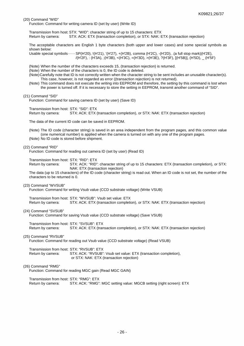
K09821;26/37
- 26 -
(20) Command “WID” Function: Command for writing camera ID (set by user) (Write ID) Transmission from host: STX: “WID”: character string of up to 15 characters: ETX Return by camera: STX: ACK: ETX (transaction completion), or STX: NAK: ETX (transaction rejection) The acceptable characters are English 1 byte characters (both upper and lower cases) and some special symbols as shown below: Usable special symbols······ SP(H'20), !(H'21), ’(H'27), +(H'2B), comma (H'2C), -(H'2D), .(a full stop mark)(H'2E),
/(H'2F), : (H'3A), ;(H'3B), <(H'3C), =(H'3D), >(H'3E), ?(H'3F), [(H'5B)], (H'5D), _ (H'5F) (Note) When the number of the characters exceeds 15, (transaction rejection) is returned. (Note) When the number of the characters is 0, the ID code is deleted. (Note) Carefully note that ID is not correctly written when the character string to be sent includes an unusable character(s).
This case, however, is not regarded as error ((transaction rejection) is not returned). (Note) This command does not execute the writing into EEPROM and therefore, the setting by this command is lost when
the power is turned off. If it is necessary to store the setting in EEPROM, transmit another command of “SID”.
(21) Command “SID” Function: Command for saving camera ID (set by user) (Save ID) Transmission from host: STX: “SID”: ETX Return by camera: STX: ACK: ETX (transaction completion), or STX: NAK: ETX (transaction rejection) The data of the current ID code can be saved in EEPROM. (Note) The ID code (character string) is saved in an area independent from the program pages, and this common value
(one numerical number) is applied when the camera is turned on with any one of the program pages. (Note) No ID code is stored before shipment.
(22) Command “RID” Function: Command for reading out camera ID (set by user) (Read ID) Transmission from host: STX: “RID”: ETX Return by camera: STX: ACK: “RID”: character string of up to 15 characters: ETX (transaction completion), or STX:
NAK: ETX (transaction rejection) The data (up to 15 characters) of the ID code (character string) is read out. When an ID code is not set, the number of the characters to be returned is 0.
(23) Command “WVSUB” Function: Command for writing Vsub value (CCD substrate voltage) (Write VSUB) Transmission from host: STX: “WVSUB”: Vsub set value: ETX Return by camera: STX: ACK: ETX (transaction completion), or STX: NAK: ETX (transaction rejection)
(24) Command “SVSUB” Function: Command for saving Vsub value (CCD substrate voltage) (Save VSUB) Transmission from host: STX: “SVSUB”: ETX Return by camera: STX: ACK: ETX (transaction completion), or STX: NAK: ETX (transaction rejection)
(25) Command “RVSUB” Function: Command for reading out Vsub value (CCD substrate voltage) (Read VSUB) Transmission from host: STX: “RVSUB”: ETX Return by camera: STX: ACK: “RVSUB”: Vsub set value: ETX (transaction completion),
or STX: NAK: ETX (transaction rejection)
(26) Command “RMG” Function: Command for reading MGC gain (Read MGC GAIN) Transmission from host: STX: “RMG”: ETX Return by camera: STX: ACK: “RMG”: MGC setting value: MGCB setting (right screen): ETX

K09821;27/37
- 27 -
(27) Command “WMG” Function: Command for writing MGC gain (Write MGC GAIN) Transmission from host: STX: “WMG”: MGC setting value: MGCB setting (right screen): ETX Return by camera: STX: ACK: ETX (transaction completion), or STX: NAK: ETX (transaction rejection) A 2 digit ASCII code from “80” to “7F” in the hexadecimal system (-128 to +127 decimal) is used for the MGCB setting value. Example) If level -1 (decimal) is set: “FF” Example) If level 90 (decimal) is set as a MGC setting value, and level -1 (decimal) is set as a MGCB setting value STX: “WMG”: “5A”: “FF”: ETX
(28) Command “ROF” Function: Command for reading offset (Read OFFSET) Transmission from host: STX: “ROF”: ETX Return by camera: STX: ACK: “RMG”: OFFSET setting value: OFFSETB setting (right screen): ETX
(29) Command “WOF” Function: Command for writing offset (Write OFFSET) Transmission from host: STX: “WMG”: OFFSET setting value: OFFSETB setting (right screen): ETX Return by camera: STX: ACK: ETX (transaction completion), or STX: NAK: ETX (transaction rejection) A 2 digit ASCII code from “20” to “E0” (32 to 224; decimal) in the hexadecimal system is used for the OFFSET setting value. Example) If level 100 (decimal) is set: ”64” A 2 digit ASCII code from “80” to “7F” (-128 to +127; decimal) in the hexadecimal system is used for the OFFSETB setting value. Example) If level +5 (decimal) is set: ”05” Example) If level 100 (decimal) is set as an OFFSET setting value and level +5 (decimal) is set as an OFFSETB setting
value: STX: “WOF”: “64”: “05”: ETX
(30) Command “RPS”
Function: Command for reading preset (Read PRESET) Transmission from host: STX: “RPS”: ETX Return by camera: STX: ACK: “RPS”: PRESET No.: ETX When gain & offset set value coincides with preset value (four levels of preset value), corresponding preset No. is read. When it does not coincide with preset value, ”0” is returned.
(31) Command “WPS” Function: Command for writing preset (Write PRESET) Transmission from host: STX: “WPS”: “PRESET No.”: ETX Return by camera: STX: ACK: ETX (transaction completion), or STX: NAK: ETX (transaction rejection) It is able to read out and use PRESET (four levels of gain preset value ) set before shipment. The following commands are used exclusively for FS11000GE.
(32) Command “RCG”
Function: Command for reading color gain (Read COLOR GAIN) Transmission from host: STX: “RCG”: “A” or ”B”: ETX Return by camera: STX: ACK: “RCG”: “A” or ”B”: RED setting value: GREEN setting value: BLUE setting value: ETX
(33) Command “WCG”
Function: Command for writing color gain (Write COLOR GAIN) Transmission from host: STX: “WCG”: “A” or ”B”: RED setting value: GREEN setting value: BLUE setting value: ETX Return by camera: STX: ACK: ETX (transaction completion), or STX: NAK: ETX(transaction rejection)
The transmitting command has the following meanings: STX: “WCG”: “A” or “B”: RED setting value: GREEN setting value: BLUE setting value: ETX
*1 *2 *1 A: The image on the left side (DUAL scan), Full image (SINGLE scan) B: The image on the right side (DUAL scan) *2 GAIN set value for each color (red, green, blue)

K09821;28/37
- 28 -
A 2 digit ASCII code from “E0” to “60” (-32 to 96; decimal) in the hexadecimal system is used for the COLOR GAIN setting value for each color.
(34) Command “RVC” Function: Command for reading video level (Read VIDEO LEVEL) Transmission from host: STX: “RVC”: “A” or ”B”: ETX Return by camera: STX: ACK: “RPS”: “AREA”: RED level: GREEN level: BLUE level: ETX A 4 digit ASCII code from “0” to “3FFF” (0 to 16383; decimal) in the hexadecimal system is used for the color level reading value.
Note in use of commands
The internal nonvolatile ROM (EEPROM) guarantees the rewritable times up to 1 million based on the specifications of the device. Accordingly, it is highly recommended to avoid such usage as the commands accompanied by writing in EEPROM including “WA to WF”, “SMC” and “e” are repeated endlessly (or almost endlessly) in the program loop on the user side.

K09821;29/37
- 29 -
8. Timing Chart Pixel clock timing (common in various operation modes)
(Note) The above timing represents the signal timing before being input to the input part of the GigE interface unit (Camera Link interface). All the synchronization signals described in this section are internal signals as the synchronization signal (FVAL,LVAL,CLK etc.) is not output to the outside in the case of GigE camera.
(Note) The image signals which are input into Camera Link interface through two taps(CH1,CH2) are output from LAN connector as the image data after forming successive single image in the GigE interface.
(!) In the case of Fx11000GE, the image signals are output in order from the left even in DUAL output mode (5fps) as they are sorted using internal buffer
Output form when in DUAL scanning
1CLK=30.8nS
10ns(max)
Clock output
Digital data
CH1/CH2
10or8or12bit
CLK
A/D
LAN
connector
Ch
ann
elL
ink
(LVAL,FVAL)
Gig
EI/
F
DEMULTIPLEX.
10/8/12bit
10/8/12bit
CH1
CH2
PCLK
1/1CLK
A/D
RJ-
45
8~12bit
8~12bit
[Phase relationship between clock output and data]
有効撮像領域V
tap1(From the left)
tap2(From the right)
Imaging area
Output direction Output direction
Conventional camera:e.g.FC5100CL 15fps(DUAL)
有効撮 像領域V
Camera Linkoutput
Tap1(From the left;Odd number)Tap2(From the left;Even number)
Imaging area
Output direction
FC11000CL 5fps(DUAL)
Ev en num bere d p ixe l
Od d-n umb ered pi xel
Sorting
Camera Linkoutput

K09821;30/37
- 30 -
Horizontal timing
LD V
SG
E ff e ct i v e p ix e ls20 04
( In ternal signal / End o fexposu re)
6 4 9 8 D U A L
8 5 3 4 S I N G L E
Digital image output
Ef f ec t iv e i m a ge pe r io d
200 4
Read-out part
407 2
(Common in DUAL/SINGLE)
Transfer part
(DUALoperation)
Du m m y
bi t s
OB
197 4 20
1
29 7
2 3
1 2 2004
LD V
2 3 0 4 In no rmal time
1 32 9 8
SUB
0
1 3 5
2003
FD V
(C H1)
3 902
Digital image output
E ff e c ti v e i ma g e p er i od
400 8
Transfer part
(SINGLE operation)
LD V
4 5 7 0 At th e s t a r t o f e x p o s u r e
SUB
1 2 3
4008
(C H1)
20 0
3
2 5 3 4 At the start o f exposu re
4 3 4 0 In no r m a l t i m e
CCDsignal output
CCDsignal output
(C H2)
2004
ST RB
ST RB
HD( In tern al s ign al)
1 1
HD( In tern al s ign al)
1
HD( internal signal)
1
20037
20 010 1
2 4 6
2001
2002
2 003 7
422 8
21 210 1
1 32 9 8
Effe ct i v e p ix e ls40 08
12 3
4008
35
Horizontal transfer
suspension time
Du m m y
bi t
OB
197 4 20
29 7
1 2
0
( In ternal s ignal / Start of exposure)
Digital image output
( In ternal signal / Startof exposure)
Horizontal transfer
suspension time
※Unless otherwise specified, the time unit of the values in the horizontal timing chart is CLK (1/32.50MHz = 30.8nS). ※Numerical values here are design values.
Color coding (Horizontal output timing)

K09821;31/37
- 31 -
Vertical timing: Continuous shutter
FV AL(F DV)
17 267 2
S G
CCD output signal
OBBlank
transfer
( In ternal signal / End o f exposu re)
16
LV AL(L DV)
1 8 8
2672
1
267 2
Effec t iv e pi x el s
28
Digital output
1 2 26 71
1 2
13 36
232 7 All p i x el re a d- o ut
136 3 Parti a l r e ad - ou t
1 3 1 6
14
1+ 2
1 386
Normal scan
Double speed scan
S UB
Exposure period Exposure period
2 6722 671
3+ 4
2669+2670
2671+2672
1+ 2
3+ 4
2669+2670
2671+2672
( Internal signal / Starto f exposu re)
CCD output signal
Digital output
Ef f ec t iv e p i xe l s
※LDV cycle is not constant. It differs between in read-out part and in image transfer part (with or without SUB). ※Refer to horizontal timing chart for the detail.
Vertical timing: High speed/preset shutter/asynchronous shutter/normal scan
FDV
LDV
28 26 72
Digital output
2 6721 2 2 671
Normal scan
Exposure period(nH) Exposure period(nH)
Vinit
HD( In ternal signal)
End of exposure(SG)
STRB
DU A L out pu t : 7 4μsec
SY N G LE out pu t :1 3 7μsec
1
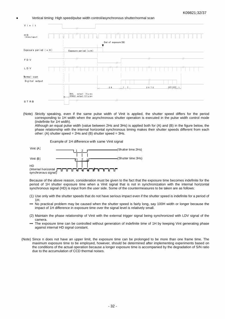
K09821;32/37
- 32 -
Vertical timing: High speed/pulse width control/asynchronous shutter/normal scan
FDV
LDV
28 26 72
Digital output
2 6721 2 2 671
Normal scan
Exposure period(nH) Exposure period(nH)
Vinit
HD( In ternal signal)
End of exposure(SG)
STRB
DU A L out pu t : 7 4μsec
SY N G LE out pu t :1 3 7μsec
1
(Note) Strictly speaking, even if the same pulse width of Vinit is applied, the shutter speed differs for the period
corresponding to 1H width when the asynchronous shutter operation is executed in the pulse width control mode (indefinite for 1H width). Although an equal pulse width (value between 2Hs and 3Hs) is applied both for (A) and (B) in the figure below, the phase relationship with the internal horizontal synchronous timing makes their shutter speeds different from each other: (A) shutter speed = 2Hs and (B) shutter speed = 3Hs.
Vinit (A)
Vinit (B)
HD (Internal horizontal synchronous signal)
Example of 1H difference with same Vinit signal
(Shutter time:2Hs)
(Shutter t ime:3Hs)
1 2
3 2
1
1
Because of the above reason, consideration must be given to the fact that the exposure time becomes indefinite for the period of 1H shutter exposure time when a Vinit signal that is not in synchronization with the internal horizontal synchronous signal (HD) is input from the user side. Some of the countermeasures to be taken are as follows: (1) Use only with the shutter speeds that do not have serious impact even if the shutter speed is indefinite for a period of
1H. ••• No practical problem may be caused when the shutter speed is fairly long, say 100H width or longer because the
impact of 1H difference in exposure time over the signal level is relatively small. (2) Maintain the phase relationship of Vinit with the external trigger signal being synchronized with LDV signal of the
camera. ••• The exposure time can be controlled without generation of indefinite time of 1H by keeping Vint generating phase
against internal HD signal constant.
(Note) Since n does not have an upper limit, the exposure time can be prolonged to be more than one frame time. The
maximum exposure time to be employed, however, should be determined after implementing experiments based on the conditions of the actual operation because a longer exposure time is accompanied by the degradation of S/N ratio due to the accumulation of CCD thermal noises.

K09821;33/37
- 33 -
Vertical timing: Low speed (prolonged exposure)/preset shutter/continuous/normal scan
VD
FDV
( Internal verticalsynchronous signal)
Exposure time(nV) Image(P )/Exposure time
Image(P-1) Image(P)Image(P+1)
Image(P +1) /Exposure time
Low speed shutter(Prolonged exposure) timing
Effective image period (2672)
Exposure time(nV)
8
1V=2327
Image signal(Digital)
Effective image period(2672)
Internal signal(Internal operation)
Image output
※The detail vertical timing of each effective image duration is same as that in “Vertical timing/continuous shutter, no shutter”case. (Note) The prolonged exposure operation and double speed scanning can not go together. (Note) This camera does not support the asynchronous shutter operation in prolonged exposure mode.

K09821;34/37
- 34 -
9. Image Display Software and API terms It can display the image on the PC monitor and can save the image data by connecting the equipment to PC via Ethernet and by using image display software (Coyote) of the attached SDK. Refer to the contents of “Instruction manual of FC-FG series camera (Connection edition)” about how to use the Display software (“Coyote” and “GEVPlayer”) This equipment meets GenICam API established by EMVA (European Machine Vision Association). The Feature(Item) and that content of GenICam API are described below.
Feature (Item) Content (Set value) Read/Write
<AcquisitionAndTriggerControls> AcquisitionMode Sets the acquisition mode of the device. R/W Continuous :Frames are captured continuously. Single Frame :One frame is captured. Multi Frame :The number of frames specified by AcquisitionFrameCount is captured. AcquisitionStart Starts the Acquisition of the device. C AcquisitionStop Stops the Acquisition of the device. C AcquisitionFrameCount Sets the number of frames to acquire in MultiFrame Acquisition mode.(1 to 255) R/W ExposureMode Sets the operation mode of the Exposure (or shutter). R/W Off : No shutter operation (The exposure time is one frame time). Timed : Continuous shutter operation with the specified exposure duration time(※1). TriggerWidth : Asynchronous shutter operation in pulse width control mode. TriggerControlled : Preset asynchronous shutter operation with the specified exposure
duration time(※1).
Timed Low : Continuous Low speed shutter operation with the specified exposure duration time(※2).
※1…The exposure time is set by the ExposureTimeRaw,the ExposureTimeAbs or by Preset 0 to 9.
※2…The exposure time is set by the ExposureTimeLowRaw,the ExposureTimeLowAbs or by Preset0 to 9.
ExposureTimeRaw Sets the Exposure time in H unit (Horizontal synchronization time). (1 to 2721) R/W ExposureTimeAbs Sets the Exposure time in microseconds. (201.99 to 193023) R/W ExposureTimeLowRaw Sets the Law speed shutter Exposure time in V unit (Vertical synchronization time).
(1 to 50) R/W
ExposureTimeLowAbs Sets the Law speed shutter Exposure time in milliseconds. (192.98 to 9649) R/W TriggerSoftware Trigger signal is generated by software.(Internal trigger is generated when “1” is given.) C PresetShutter Sets the Exposure time with Preset value. R/W Shutter SW: Exposure time is set by the shutter SW of the camera. Preset0 : Specifies Preset value 0(Shutter exposure time is OFF only.) Preset1: Specifies Preset value 1 …. Preset9: Specifies Preset value 9 Exposure Time: Exposure time is specified by ExposureTimeRaw or ExpposureTimeAbs <ImageSizeControl> SensorWidth Effective width of the sensor in pixels. (4008) R SensorHight Effective height of the sensor in pixels.(2672) R Width Width of the Image provided by the device (in pixels).(8 to WidthMax) R/W Height Height of the image provided by the device (in pixels).(1 to HeightMax) R/W WidthMax Maximum width (in pixels) of the image. (4008) R HeightMax Maximum height (in pixels) of the image. (2672) R OffsetX Horizontal offset from the origin to the AOI (in pixels). (0 to (WidthMax-Width)) inc=2 R/W OffsetY Vertical offset from the origin to the AOI (in pixels). (0 to (HeightMax-Height)) inc=2 R/W SensorDigitizationTaps(EX) Number of taps for image output. (One) R PixelFormat Sets the output format (gray level) of the image. R/W Mono8 (FC11000GE) /BayerRG8 (FS11000GE) :Output in 8bit format Mono10 (FC11000GE) /BayerRG10 (FS11000GE) :Output in 10bit format Mono12 (FC11000GE) /BayerRG12 (FS11000GE) :Output in 12bit format <AnalogControls> GainRaw Sets the gain set value in MGC mode. (0 to 255) R/W BlackLevelRaw Sets the black level (Image offset level) (0 to 255) R/W
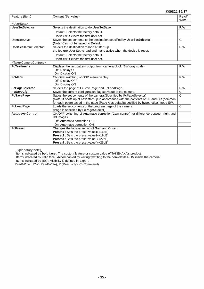
K09821;35/37
- 35 -
Feature (Item) Content (Set value) Read/Write
<UserSets> UserSetSelector Selects the destination to do UserSetSave. R/W Default: Selects the factory default.
UserSet1: Selects the first user set. UserSetSave Saves the set contents to the destination specified by UserSetSelector.
(Note) Can not be saved to Default. C
UserSetDefaultSelector Selects the destination to load at start-up. the feature User Set to load and make active when the device is reset.
R/W
Default: Selects the factory default.
UserSet1: Selects the first user set. <TakexCameraControls> FcTestImage Displays the test pattern output from camera block.(BW gray scale) R/W Off: Display OFF On: Display ON FcMenu ON/OFF switching of OSD menu display R/W Off: Display OFF On: Display ON FcPageSelector Selects the page of FcSavePage and FcLoadPage R/W FcSaveCfg Saves the current configuration flag set value of the camera. C FcSavePage Saves the set contents of the camera.(Specified by FcPageSelector) C (Note) it boots up at next start-up in accordance with the contents of FR and CR (common
for each page) saved in the page (Page A as default)specified by hypothetical mode SW.
FcLoadPage Loads the set contents of the program page of the camera. (Page is specified by FcPageSelector)
C
AutoLevelControl ON/OFF switching of Automatic correction(Gain control) for difference between right and left images.
Off: Automatic correction OFF On: Automatic correction ON FcPreset Changes the factory setting of Gain and Offset Preset1 : Sets the preset value1(+16dB) Preset2 : Sets the preset value2(+19dB) Preset3 : Sets the preset value3(+22dB) Preset4 : Sets the preset value4(+25dB)
[Explanatory note] Items indicated by bold face : The custom feature or custom value of TAKENAKA’s product. Items indicated by italic face : Accompanied by writing/rewriting to the nonvolatile ROM inside the camera. Items indicated by (Ex) : Visibility is defined in Expert.
Read/Write : R/W (Read/Write), R (Read only). C (Command)

K09821;36/37
- 36 -
10. Notes This equipment is not allowed to be used for medical purposes, detection of hazardous materials or any other operations of
which performance may exert influence on human lives or safety. We assume no responsibility whatsoever for any incidental damages (loss of business interests, business interruption,
change in data, loss of data etc.) resulting from the user’s use of this equipment or performance failure. Do not disassembly this equipment or alter the internal circuits. Accidents such as a fire may be caused by the heat
generation associated with failure in operation. This equipment achieves 5fps high frame rate for 11 megapixels by employing dual output CCD. It may have some luminance
difference (color difference) between right and left image signals, as the signal goes through the analog circuit. Also, as luminance may vary over time, it is recommended to use this equipment making readjustment regularly.
More stable images can be obtained by leaving the equipment for 20 to 30 minutes after power-on. Refrain from connecting or disconnecting cables and connectors while power is being supplied, otherwise troubles may be
caused. Fix a lens or implement other measures when using with a large or heavy lens, so that no extraordinarily large force is applied
to the camera. Connect this equipment to a high quality power source unit that does not contain noise components. Take appropriate measures to control the generation of noise if a power machine or other installations in the close
neighborhood of this equipment radiates noise, which might adversely affect this equipment. Do not use this equipment in an environment subject to any temperatures other than that of the specifications or
condensation, or on a place subject to considerable dust or constant vibration/impact. When this equipment is not used over a prolonged period of time, isolate the power from the equipment and remove the
power cable and external connection cables. When an abnormal or failure condition is detected, immediately stop using this equipment, cut off the power supply, remove
the external connection cables and contact the dealer for inspection/repair. The specifications and operational details described in the catalogues, manuals and others are subject to change for
performance improvement or other reasons without notice. [Countermeasure for time degradation of image sensor ] [Pixel defect on image sensor ] [Fixing screw for the camera]
[Important] Beware of a screw length when fixing the camera to a mounting bracket or a metal plate at user’s site. The screw length should not exceed the value designated in “External dimensions” on the end of this document. If it exceeds the value, there is a possibility that the contents of the camera are broken.
[Important] On the usage of this equipment, please note the following to prevent the problem of time degradation of CCD image sensor(Increase of pixel defects etc.). Do not use this equipment in an environment subject to high temperatures and high humidity.
Especially in a high-temperature environment, degradation of CCD image sensor is accelerated, and pixel defects such as sunspot may be caused. It is recommended that the equipment is used in an ambient temperature around normal room temperature (below 30 degrees) as far as possible. If there is any concern that ambient temperature of the camera may be heated up when embedded in the apparatus, please consider to use a cooling equipment such as a cooling fan.
Be careful not to get the light receiving surface be exposed to high intensity light over a long periods of time. If a right receiving surface is exposed to high intensity light over a long time (regardless of the on/off state of the camera), the color filter on a surface of CCD image sensor may get discolored or get burnt in and normal image could not be output. Please reduce the amount of incoming light by using dark filter or by stopping down the aperture of the lens if the high intensity light like sunlight enters over a long periods of time. The amount of light falling on the light receiving surface does not decrease with an adjustment of output level by getting electronic shutter speed higher, therefore note that discoloration or burn-in of image sensor can not be prevented that way. When this equipment is not used for a long time, it is recommended to store the equipment disconnecting the cable and fixing a lens cap.
[Important] New pixel defect may be generated or the defect level of some pixels may increase over time after shipment according to inherent nature of image sensor. Number or level of pixel defect of image sensor may inevitably increase after purchase under natural conditions. However, it does not arise from structural failure or design failing of the camera. Therefore, please be aware that such increase of number or level of pixel defect is not covered by warranty.
Camera body
Mounting bracket etc.
Never exceed predetermineddepth of threaded hole
Fixing screw

K09821;37/37
- 37 -
11. Specifications
(Note) The specifications are subject to change without notice for improvement. 12. External dimensions
Image sensor
Progressive scanning, interline transfer CCD Diagonal 43mm imaging area size Unit cell size: 9.0um(H) × 9.0um(V) square grid pattern
FC11000GE: Monochrome image sensor FS11000GE: Color image sensor (RGB Bayer array)
Number of effective pixels 4008 (H)×2672(V)
Read out scanning
Horizontal scanning frequency: fH = 14.1 KHz(DUAL) : 7.5 KHz(SINGLE) Vertical scanning frequency: fV = 5.1 Hz(DUAL) : 2.7 Hz(SINGLE) Pixel clock frequency: fCLK=32.50 MHz * Horizontal / vertical scanning frequency is a typical value.
Standard sensitivity 800Lx F22 (FC11000GE) * 800Lx F22 (FS11000GE) * (* Digital output with exposure time of 1/30 seconds and 512/1024 gray scale)
Minimum subject illuminance 1 Lx at F1.4 (FC11000GE) 2 Lx at F1.4 (FS11000GE)
S/N Approx. 50dB
Video output signal
Progressive scanning: 5.1 frame/second (DUAL) 2.7 frame/second (SINGLE) Digital output: 10 or 8 or 12 bit GigE Vision compliant (Gigabit Ethernet) 32.5MHz×2tap output (DUAL) 32.5MHz×1tap output (SINGLE)
External sync input Internal synchronization only
Electronic shutter 1/2000sec. to 1/5 sec. (no shutter) to 1/0.51 sec (DUAL) 1/1200sec. to 1/2.7 sec. (no shutter) to 1/0.27 sec (SINGLE)
Asynchronous shutter Preset fixed shutter / pulse width control Scanning mode Normal scan (all pixels) / Double speed scan Lens mount F mount (flange back fixed) External control Serial interface via Ethernet
Special functions Function of imposing setting information over image screen Function of monitoring internal temperature of camera Function of storing camera ID information
Strobe signal output OFF / Exposure start timing signal / Busy signal (+5V logic level) Power supply DC12V±10%, 500mA (typical value) Operation ambient temperature 0°C to 40°C (Shall be free from dew condensation and frost.)
Storage temperature range -30°C to 60°C (Shall be free from dew condensation and frost.)
Anti-shock 70G Anti-vibration 7G External dimension 64(W) × 64(H) × 94(L) mm (excluding tripod attachment) Weight Approx. 500 g
64
64
8
φ63.8
6331
39.7 17.5 17.5
2-M6
1/4"-20UNC
F-Mount 34.5
FB:46.5
2-M2.6 (Four faces)
18
※ Use M2.6x8mm to fix Tripod
Fig.11-1 FC11000GE/FS11000GE External views