jvc hr-a42u
40
HR-A42U HR-A22U VIDEO CASSETTE RECORDER INSTRUCTIONS PU30425-1782-1 For Customer Use: Enter below the Serial No. which is located on the rear of cabinet. Retain this information for future reference. Model No. HR-A42U/HR-A22U Serial No. TV TV/VIDEO TIMER DISPLAY ADD ENTER SP/EP 1 2 3 4 5 6 7 8 0 9 TV VOL. CH MENU OK CANCEL qREC 6PAUSE 5STOP 4PLAY FFzz3 2zzREW SKIP SEARCH TSEARCH Y DAILY WEEKLY C.RESET/ CH.SKIP TV operation – Press and hold TV button, then press POWER, CH 5/∞, TV/VIDEO AUX OSD POWER POWER MENU VIDEO AUDIO OK REC q PLAY REW 2 FF 3 PAUSE 6 STOP/EJECT 5/8 H M S ITR TIMER VIDEO SP EP AM PM REC PAUSE PLAY CH
-
Upload
alex-dedalus -
Category
Documents
-
view
247 -
download
0
description
vcr
Transcript of jvc hr-a42u
HR-A42U HR-A22U
VIDEO CASSETTE RECORDER
INSTRUCTIONS
PU30425-1782-1
For Customer Use: Enter below the Serial No. which is located on the rear of cabinet. Retain this information for future reference. Model No. HR-A42U/HR-A22U Serial No.
TV TV/VIDEO TIMER
DISPLAY
ADD
ENTER
SP/EP
1 2 3
4 5 6
7 8
0
9
TV VOL.CH
MENU OK
CANCEL
q REC 6 PAUSE5 STOP
4PLAY FFzz32zzREW
SKIP SEARCHT SEARCH Y
DAILY WEEKLY
C.RESET/ CH.SKIP
TV operation – Press and hold TV button, then press POWER, CH 5/∞, TV/VIDEO
AUX
OSD
POWER
POWER
MENUVIDEO AUDIO
OK
REC q
PLAY
REW 2
FF 3
PAUSE 6
STOP/EJECT 5/8
H M S
I T R TIMER
VIDEO SPEP
AMPM
R E C
PAUSEPLAY
CH

2Dear Customer,Thank you for purchasing the JVC VHS video cassette recorder. Before use, please read the safety information and precautionscontained in the following pages to ensure safe use of your new VCR.
CAUTIONS
WARNING:TO PREVENT FIRE OR SHOCKHAZARD, DO NOT EXPOSE THISUNIT TO RAIN OR MOISTURE.CAUTION:This video cassette recorder should be used with AC120V`, 60Hz only.To prevent electric shocks and fire hazards, DO NOT useany other power source.
CAUTION:TO PREVENT ELECTRIC SHOCK, MATCH WIDEBLADE OF PLUG TO WIDE SLOT, FULLY INSERT.
ATTENTION:POUR ÉVITER LES CHOCS ÉLECTRIQUES, INTRODUIRELA LAME LA PLUS LARGE DE LA FICHE DANS LA BORNECORRESPONDANTE DE LA PRISE ET POUSSERJUSQU'AU FOND.
CAUTION RISK OF ELECTRIC SHOCK
DO NOT OPEN
CAUTION: TO REDUCE THE RISK OF ELECTRIC SHOCK. DO NOT REMOVE COVER (OR BACK).
NO USER-SERVICEABLE PARTS INSIDE. REFER SERVICING TO QUALIFIED SERVICE PERSONNEL.
The lightning flash with arrowhead symbol, within an equilateral triangle, is intended to alert the user to the presence of uninsulated "dangerous voltage" within the product's enclosure that may be of sufficient magnitude to constitute a risk of electric shock to persons.
The exclamation point within an equilateral triangle is intended to alert the user to the presence of important operating and maintenance (servicing) instructions in the literature accompanying the appliance.
Failure to heed the following precautions may result indamage to the VCR, remote control or video cassette.1. DO NOT place the VCR . . .
... in an environment prone to extreme temperatures orhumidity.
... in direct sunlight.
... in a dusty environment.
... in an environment where strong magnetic fields aregenerated.
... on a surface that is unstable or subject to vibration.2. DO NOT block the VCR’s ventilation openings.3. DO NOT place heavy objects on the VCR or remote control.4. DO NOT place anything which might spill on top of the
VCR or remote control.5. AVOID violent shocks to the VCR during transport.
**MOISTURE CONDENSATIONMoisture in the air will condense on the VCR when you move itfrom a cold place to a warm place, or under extremely humidconditions—just as water droplets form on the surface of a glassfilled with cold liquid. Moisture condensation on the head drumwill cause damage to the tape. In conditions where condensa-tion may occur, keep the VCR’s power turned on for a fewhours to let the moisture dry.
**ABOUT HEAD CLEANINGAccumulation of dirt and other particles on the video headsmay cause the playback picture to become blurred or inter-rupted. Be sure to contact your nearest JVC dealer if suchtroubles occur.
Note to CATV system installer:This reminder is provided to call the CATV systeminstaller's attention to Article 820-40 of the NEC thatprovides guidelines for proper grounding and, in particular,specifies that the cable ground shall be connected to thegrounding system of the building, as close to the point ofcable entry as practical.
CAUTION:Changes or modifications not approved by JVC could voiduser's authority to operate the equipment. n Cassettes marked "VHS" (or "S-VHS") can be used with this
video cassette recorder. However, only "VHS" recordings canbe played back in this model.
n HQ VHS is compatible with existing VHS equipment.

3IMPORTANT PRODUCTSAFETY INSTRUCTIONSElectrical energy can perform many useful functions. Butimproper use can result in potential electrical shock or firehazards. This product has been engineered and manufacturedto assure your personal safety. In order not to defeat the built-insafeguards, observe the following basic rules for its installation,use and servicing.
ATTENTION:Follow and obey all warnings and instructions marked on yourproduct and its operating instructions. For your safety, pleaseread all the safety and operating instructions before you operatethis product and keep this booklet for future reference.
INSTALLATION1. Grounding or Polarization(A) Your product may be equipped with a polarized alternating-
current line plug (a plug having one blade wider than theother). This plug will fit into the power outlet only one way.This is a safety feature.If you are unable to insert the plug fully into the outlet, tryreversing the plug. If the plug should still fail to fit, contactyour electrician to replace your obsolete outlet. Do notdefeat the safety purpose of the polarized plug.
(B) Your product may be equipped with a 3-wire grounding-typeplug, a plug having a third (grounding) pin. This plug willonly fit into a grounding-type power outlet. This is a safetyfeature.If you are unable to insert the plug into the outlet, contactyour electrician to replace your obsolete outlet. Do notdefeat the safety purpose of the grounding-type plug.
2. Power SourcesOperate your product only from the type of power sourceindicated on the marking label. If you are not sure of the type ofpower supply to your home, consult your product dealer orlocal power company. If your product is intended to operatefrom battery power, or other sources, refer to the operatinginstructions.
3. OverloadingDo not overload wall outlets, extension cords, or integralconvenience receptacles as this can result in a risk of fire orelectric shock.
4. Power Cord ProtectionPower supply cords should be routed so that they are not likelyto be walked on or pinched by items placed upon or againstthem, paying particular attention to cords at plugs, conveniencereceptacles, and the point where they exit from the product.
5. VentilationSlots and openings in the cabinet are provided for ventilation.To ensure reliable operation of the product and to protect itfrom overheating, these openings must not be blocked orcovered.• Do not block the openings by placing the product on a bed,
sofa, rug or other similar surface.• Do not place the product in a built-in installation such as a
bookcase or rack unless proper ventilation is provided or themanufacturer’s instructions have been adhered to.
6. Wall or Ceiling MountingThe product should be mounted to a wall or ceiling only asrecommended by the manufacturer.
ANTENNA LEAD IN WIRE
ANTENNA DISCHARGE UNIT (NEC SECTION 810-20)
GROUNDING CONDUCTORS (NEC SECTION 810-21)
GROUND CLAMPS
POWER SERVICE GROUNDING ELECTRODE SYSTEM (NEC ART 250. PART H)
NEC – NATIONAL ELECTRICAL CODE
ELECTRIC SERVICE EQUIPMENT
EXAMPLE OF ANTENNA GROUNDING AS PER NATIONAL ELECTRICAL CODE, ANSI/NFPA 70
GROUND CLAMP
ANTENNA INSTALLATIONINSTRUCTIONS1. Outdoor Antenna GroundingIf an outside antenna or cable system is connected to theproduct, be sure the antenna or cable system is grounded so asto provide some protection against voltage surges and built-upstatic charges. Article 810 of the National Electrical Code,ANSI/NFPA 70, provides information with regard to propergrounding of the mast and supporting structure, grounding ofthe lead-in wire to an antenna discharge unit, size of groundingconnectors, location of antenna discharge unit, connection togrounding electrodes, and requirements for the groundingelectrode.
2. LightningFor added protection for this product during a lightning storm,or when it is left unattended and unused for long periods oftime, unplug it from the wall outlet and disconnect the antennaor cable system. This will prevent damage to the product due tolightning and power-line surges.
3. Power LinesAn outside antenna system should not be located in the vicinityof overhead power lines or other electric light or power circuits,or where it can fall into such power lines or circuits. Wheninstalling an outside antenna system, extreme care should betaken to keep from touching such power lines or circuits ascontact with them might be fatal.
4SERVICING1. ServicingIf your product is not operating correctly or exhibits a markedchange in performance and you are unable to restore normaloperation by following the detailed procedure in its operatinginstructions, do not attempt to service it yourself as opening orremoving covers may expose you to dangerous voltage or otherhazards. Refer all servicing to qualified service personnel.
2. Damage Requiring ServiceUnplug this product from the wall outlet and refer servicing toqualified service personnel under the following conditions:a.When the power supply cord or plug is damaged.b.If liquid has been spilled, or objects have fallen into the
product.c. If the product has been exposed to rain or water.d.If the product does not operate normally by following the
operating instructions. Adjust only those controls that arecovered by the operating instructions as an improperadjustment of other controls may result in damage and willoften require extensive work by a qualified technician torestore the product to its normal operation.
e. If the product has been dropped or damaged in any way.f. When the product exhibits a distinct change in
performance—this indicates a need for service.
3. Replacement PartsWhen replacement parts are required, be sure the servicetechnician has used replacement parts specified by themanufacturer or have the same characteristics as the originalpart. Unauthorized substitutions may result in fire, electricshock or other hazards.
4. Safety CheckUpon completion of any service or repairs to this product, askthe service technician to perform safety checks to determinethat the product is in safe operating condition.
HOW TO USE THIS INSTRUCTIONMANUAL● All major sections and subsections are listed in the Table Of
Contents on page 5. Use this when searching for informationon a specific procedure or feature.
● The Index on pages 35–37 lists frequently-used terms, andthe number of the first page on which they are used orexplained in the manual. This section also illustrates thecontrols and connections on the front and rear panel, thefront display panel and the remote control.
● The Z mark signals a reference to another page forinstructions or related information.
● Operation buttons necessary for the various procedures areclearly indicated through the use of illustrations at thebeginning of each major section.
BEFORE YOU INSTALL YOUR NEWVCR . . .. . . please read the sections/literature listed below.● ”Cautions” on page 2● ”Important Products Safety Instructions” on the previous pages
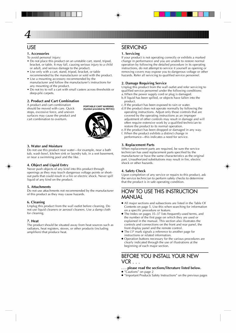
USE1. AccessoriesTo avoid personal injury:• Do not place this product on an unstable cart, stand, tripod,
bracket, or table. It may fall, causing serious injury to a childor adult, and serious damage to the product.
• Use only with a cart, stand, tripod, bracket, or tablerecommended by the manufacturer or sold with the product.
• Use a mounting accessory recommended by themanufacturer and follow the manufacturer’s instructions forany mounting of the product.
• Do not try to roll a cart with small casters across thresholds ordeep-pile carpets.
2. Product and Cart CombinationA product and cart combinationshould be moved with care. Quickstops, excessive force, and unevensurfaces may cause the product andcart combination to overturn.
3. Water and MoistureDo not use this product near water—for example, near a bathtub, wash bowl, kitchen sink or laundry tub, in a wet basement,or near a swimming pool and the like.
4. Object and Liquid EntryNever push objects of any kind into this product throughopenings as they may touch dangerous voltage points or short-out parts that could result in a fire or electric shock. Never spillliquid of any kind on the product.
5. AttachmentsDo not use attachments not recommended by the manufacturerof this product as they may cause hazards.
6. CleaningUnplug this product from the wall outlet before cleaning. Donot use liquid cleaners or aerosol cleaners. Use a damp clothfor cleaning.
7. HeatThe product should be situated away from heat sources such asradiators, heat registers, stoves, or other products (includingamplifiers) that produce heat.
PORTABLE CART WARNING (Symbol provided by RETAC)

5CONTENTS
EDITING 28Edit To Or From Another VCR ............... 28Edit From A Camcorder ....................... 29
SPECIAL FEATURES 30Multi-Brand Remote Control ................ 30
T ROUBLESHOOTING 31Power .................................................31Tape Transport .....................................31Playback .............................................31Recording ............................................31Timer Recording ...................................32Other Problems....................................32
QUESTIONS AND ANSWERS 33Playback .............................................33Recording ............................................33Timer Recording ...................................33
SPECIFICATIONS 34
INDEX 35
List Of Terms ........................................35Front View ...........................................36Rear View ...........................................36Front Display Panel ..............................37Remote Control ....................................37
FOR SERVICING 38
WARRANTY 39
INSTALLING YOUR NEW VCR 6Basic Connections ..................................6
INITIAL SETTINGS 7Clock (for HR-A42U) ...............................7
Automatic Clock Setting ................................... 7Preparation .......................................................7Language Select ............................................... 8Clock Setting .....................................................8
Auto ...............................................................8Semi-Auto ......................................................9Manual ........................................................10
Clock (for HR-A22U) .............................11Preparation ..................................................... 11Language Select .............................................. 11Clock Setting ...................................................12
Tuner ...................................................13Set Receivable Channels ................................ 13Add Or Delete A Channel .............................. 15
SIMPLE PLAYBACK ANDRECORDING 16
Simple Playback ..................................16Simple Recording .................................17
PLAYBACK AND RECORDINGFEATURES 18
Playback .............................................18Still Picture ......................................................18Slow, Reverse, Reverse Slow Or Fast-MotionPicture ............................................................18Manual Tracking............................................. 19Superimpose ...................................................20Skip Search .....................................................21Repeat Playback ............................................. 21Index Search ...................................................21Counter Reset ..................................................22Tape Position Indicator ................................... 22Next-Function Memory .................................. 22
Recording ............................................23Record One Program WhileWatching Another .......................................... 23Display Elapsed Recording Time..................... 23
TIMER RECORDING 24Instant Timer Recording (ITR) ............... 24On-Screen Timer Programming ........... 24
Check And Cancel Programs .......................... 26Auto Timer ......................................................27

6
CH3 CH4
VIDEO
INSTALLING YOUR NEW VCR
CHECK CONTENTS
1 Make sure the package contains all of the accessorieslisted in “SPECIFICATIONS” (Z pg. 34).
SITUATE VCR
2 Place the VCR on a stable, horizontal surface.
CONNECT VCR TO TV
3 The connection method you use depends on the type ofTV you have.
RF Connection● To Connect To A TV With NO AV Input Terminals . . .
a– Disconnect the TV antenna from the TV.b– Connect the TV antenna cable to the ANT IN jack
on the rear of the VCR.c– Connect the supplied RF cable between the RF
OUT jack on the rear of the VCR and the TV’santenna terminal.
AV Connection● To Connect To A TV With AV Input Terminals . . .
a– Connect the antenna, VCR and TV as shown inthe illustration.
b– Connect an Audio/Video Cable (not supplied)between the AUDIO OUT and VIDEO OUT jacks onthe rear of the VCR and the AV IN jacks on the TV.
CONNECT VCR TOPOWER SOURCE
4 Connect the power plug to an AC outlet.
● HR-A42U owners — the clock will automatically beset when the antenna is connected and when the ACis first connected to the VCR (Z pg. 7).
FINAL PREPARATION FORUSE
5 Select the VCR channel (3 or 4) by setting the switchon the rear of the VCR as shown in the illustration.
Turn on the TV's power. You are now able to performsimple playback (Z pg. 16) and recording (Z pg. 17).
NOTES:● The VCR channel is the channel on the TV which will display
the audio and video signals from the VCR. The VCR's CH3–CH4 switch sets the VCR channel to CH3 or CH4.
● The CH3–CH4 switch is preset to the CH3 position.Set to CH4 if CH3 is used for broadcasting in your area.
● If your TV has no AV input terminals, set the channel on theTV to correspond to the CH3–CH4 switch on the back of theVCR.
● Even if your TV has AV input terminals, you must connect itto the VCR using an RF cable in order to record one showwhile watching another (Z pg. 23).
● For full identification of the VCR's rear panel, refer to theIndex (REAR VIEW Z pg. 36).
BasicConnections
Antenna or Cable
Flat Feeder
Coaxial Cable
AC PowerCord
Back of VCR
Maching Transformer
AC Outlet
RFOUT
RF Cable(provided)
75 ohm terminal
ANTENNA-IN(Antenna or Cable input)
Back of VCR
TV
7INITIAL SETTINGS
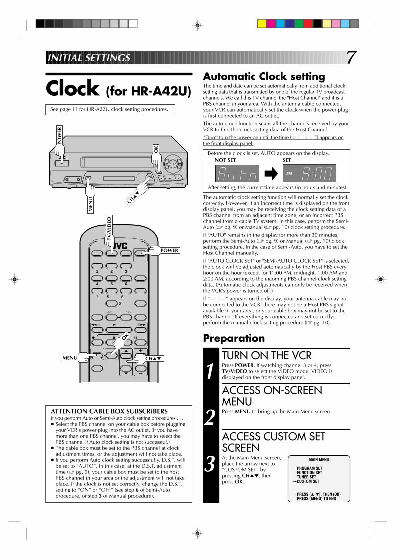
Clock (for HR-A42U)
TURN ON THE VCR
1 Press POWER. If watching channel 3 or 4, pressTV/VIDEO to select the VIDEO mode. VIDEO isdisplayed on the front display panel.
ACCESS ON-SCREENMENU
2 Press MENU to bring up the Main Menu screen.
ACCESS CUSTOM SETSCREEN
3 At the Main Menu screen,place the arrow next to“CUSTOM SET” bypressing CH5∞, thenpress OK.
Preparation
MAIN MENU
PROGRAM SETFUNCTION SETTUNER SET
=CUSTOM SET
PRESS (5,∞), THEN (OK)PRESS (MENU) TO END
Automatic Clock settingThe time and date can be set automatically from additional clocksetting data that is transmitted by one of the regular TV broadcastchannels. We call this TV channel the "Host Channel" and it is aPBS channel in your area. With the antenna cable connected,your VCR can automatically set the clock when the power plugis first connected to an AC outlet.The auto clock function scans all the channels received by yourVCR to find the clock setting data of the Host Channel.*Don’t turn the power on until the time (or “- - : - - ”) appears onthe front display panel.
Before the clock is set, AUTO appears on the display.
After setting, the current time appears (in hours and minutes).
The automatic clock setting function will normally set the clockcorrectly. However, if an incorrect time is displayed on the frontdisplay panel, you may be receiving the clock setting data of aPBS channel from an adjacent time zone, or an incorrect PBSchannel from a cable TV system. In this case, perform the Semi-Auto (Z pg. 9) or Manual (Z pg. 10) clock setting procedure.If "AUTO" remains in the display for more than 30 minutes,perform the Semi-Auto (Z pg. 9) or Manual (Z pg. 10) clocksetting procedure. In the case of Semi-Auto, you have to set theHost Channel manually.If "AUTO CLOCK SET" or "SEMI-AUTO CLOCK SET" is selected,the clock will be adjusted automatically by the Host PBS everyhour on the hour (except for 11:00 PM, midnight, 1:00 AM and2:00 AM) according to the incoming PBS channel clock settingdata. (Automatic clock adjustments can only be received whenthe VCR’s power is turned off.)If “- - : - - ” appears on the display, your antenna cable may notbe connected to the VCR, there may not be a Host PBS signalavailable in your area, or your cable box may not be set to thePBS channel. If everything is connected and set correctly,perform the manual clock setting procedure (Z pg. 10).
ATTENTION CABLE BOX SUBSCRIBERSIf you perform Auto or Semi-Auto clock setting procedures . . .● Select the PBS channel on your cable box before plugging
your VCR's power plug into the AC outlet. (If you havemore than one PBS channel, you may have to select thePBS channel if Auto clock setting is not successful.)
● The cable box must be set to the PBS channel at clockadjustment times, or the adjustment will not take place.
● If you perform Auto clock setting successfully, D.S.T. willbe set to “AUTO”. In this case, at the D.S.T. adjustmenttime (Z pg. 9), your cable box must be set to the hostPBS channel in your area or the adjustment will not takeplace. If the clock is not set correctly, change the D.S.T.setting to “ON” or “OFF” (see step 6 of Semi-Autoprocedure, or step 3 of Manual procedure).
1 2 3
4 5 6
7 8
0
9
q 65
4
YT
2 3
q
2
3
6
5/8
TV/V
IDEO
OK
POWER
MENU
POW
ER
MEN
U
OK
CH5∞
CH5∞
See page 11 for HR-A22U clock setting procedures.
AM
SETNOT SET
8
q
2
3
6
5/8
MEN
U
CH
INITIAL SETTINGS (cont.)
CH
1 2 3
4 5 6
7 8
0
9
q 65
4
YT
2 3
OK
CHMENU
OK
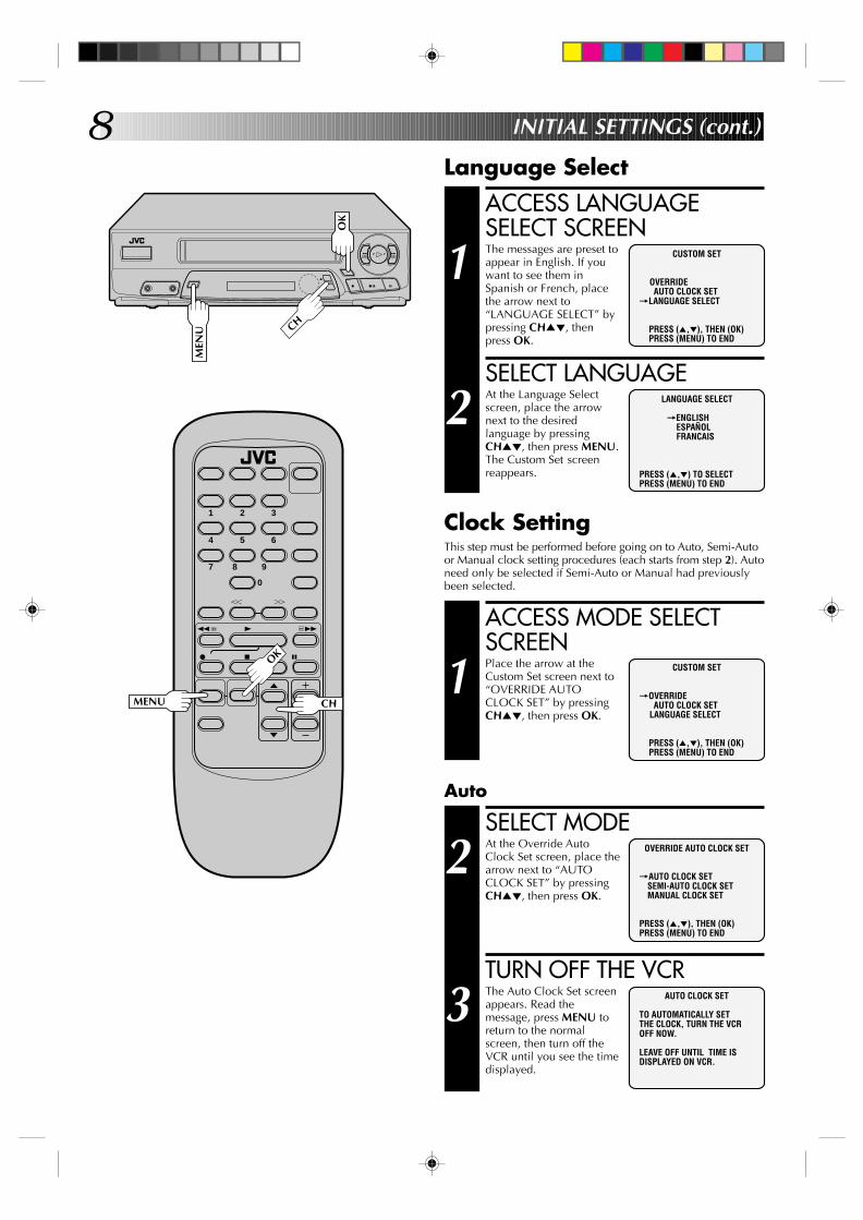
Language Select
LANGUAGE SELECT
=ENGLISHESPAÑOLFRANCAIS
PRESS (5,∞) TO SELECTPRESS (MENU) TO END
CUSTOM SET
OVERRIDEAUTO CLOCK SET
=LANGUAGE SELECT
PRESS (5,∞), THEN (OK)PRESS (MENU) TO END
ACCESS LANGUAGESELECT SCREEN
1 The messages are preset toappear in English. If youwant to see them inSpanish or French, placethe arrow next to“LANGUAGE SELECT” bypressing CH5∞, thenpress OK.
SELECT LANGUAGE
2 At the Language Selectscreen, place the arrownext to the desiredlanguage by pressingCH5∞, then press MENU.The Custom Set screenreappears.
Auto
SELECT MODE
2 At the Override AutoClock Set screen, place thearrow next to “AUTOCLOCK SET” by pressingCH5∞, then press OK.
TURN OFF THE VCR
3 The Auto Clock Set screenappears. Read themessage, press MENU toreturn to the normalscreen, then turn off theVCR until you see the timedisplayed.
OVERRIDE AUTO CLOCK SET
=AUTO CLOCK SETSEMI-AUTO CLOCK SETMANUAL CLOCK SET
PRESS (5,∞), THEN (OK)PRESS (MENU) TO END
AUTO CLOCK SET
TO AUTOMATICALLY SETTHE CLOCK, TURN THE VCROFF NOW.
LEAVE OFF UNTIL TIME ISDISPLAYED ON VCR.
Clock SettingThis step must be performed before going on to Auto, Semi-Autoor Manual clock setting procedures (each starts from step 2). Autoneed only be selected if Semi-Auto or Manual had previouslybeen selected.
ACCESS MODE SELECTSCREEN
1 Place the arrow at theCustom Set screen next to“OVERRIDE AUTOCLOCK SET” by pressingCH5∞, then press OK.
CUSTOM SET
=OVERRIDEAUTO CLOCK SET
LANGUAGE SELECT
PRESS (5,∞), THEN (OK)PRESS (MENU) TO END
9
q
2
3
6
5/8
MEN
U
1 2 3
4 5 6
7 8
0
9
q 65
4
YT
2 3
CHMENU
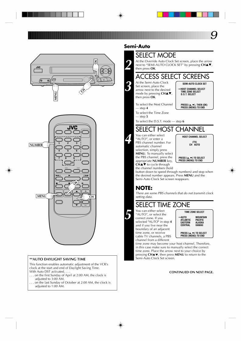
Semi-Auto
OK
OK
**AUTO DAYLIGHT SAVING TIMEThis function enables automatic adjustment of the VCR’sclock at the start and end of Daylight Saving Time.With Auto DST activated, . . .. . . on the first Sunday of April at 2:00 AM, the clock is
adjusted to 3:00 AM.. . . on the last Sunday of October at 2:00 AM, the clock is
adjusted to 1:00 AM.
SELECT MODE
2 At the Override Auto Clock Set screen, place the arrownext to “SEMI-AUTO CLOCK SET” by pressing CH▲▼,then press OK.
ACCESS SELECT SCREENS
3 At the Semi-Auto ClockSet screen, place thearrow next to the desiredmode by pressing CH▲▼,then press OK.
To select the Host Channel— step 4To select the Time Zone— step 5To select the D.S.T. mode — step 6
SELECT HOST CHANNEL
4 You can either select“AUTO”, or enter aPBS channel number. Forautomatic channelselection, simply pressMENU. To manually selectthe PBS channel, press theappropriate NUMBER key,CH▲▼ to cycle throughthe channel numbers (holdbutton down to speed through numbers) and stop whenthe desired number appears. Press MENU and theSemi-Auto Clock Set screen reappears.
NOTE:There are some PBS channels that do not transmit clocksetting data.
SELECT TIME ZONE
5 You can either select“AUTO”, or select thecorrect zone. If youselected "AUTO" in step 4and if you live near theboundary of an adjacenttime zone, or receivecable TV channels, a PBSchannel from a differenttime zone may become your host channel. Therefore,in this case make sure to manually select the correcttime zone. Place the arrow next to your choice bypressing CH5∞, then press MENU to return to theSemi-Auto Clock Set screen.
SEMI-AUTO CLOCK SET
=HOST CHANNEL SELECTTIME ZONE SELECTD.S.T. SELECT
PRESS (5,∞), THEN (OK)PRESS (MENU) TO END
HOST CHANNEL SELECT
(TV)CH AUTO
PRESS (5,∞) TO SELECTPRESS (MENU) TO END
CH
TIME ZONE SELECT
=AUTO MOUNTAINATLANTIC PACIFICEASTERN ALASKACENTRAL HAWAII
PRESS (5,∞) TO SELECTPRESS (MENU) TO END
CONTINUED ON NEXT PAGE.
NUMBER
10
q
2
3
6
5/8
OK
CH
1 2 3
4 5 6
7 8
0
9
q 65
4
YT
2 3
MEN
U
MENU
INITIAL SETTINGS (cont.)
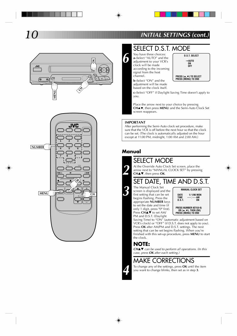
SELECT D.S.T. MODE
6 You have three choices:a–Select “AUTO” and theadjustment to your VCR’sclock will be madeaccording to the incomingsignal from the hostchannel.b–Select “ON” and theadjustment will be madebased on the clock itself.c–Select “OFF” if Daylight Saving Time doesn’t apply toyou.
Place the arrow next to your choice by pressingCH5∞, then press MENU and the Semi-Auto Clock Setscreen reappears.
D.S.T. SELECT
=AUTOONOFF
PRESS (5,∞) TO SELECTPRESS (MENU) TO END
NUMBER
OK
CH
Manual
SELECT MODE
2 At the Override Auto Clock Set screen, place thearrow next to “MANUAL CLOCK SET” by pressingCH▲▼, then press OK.
SET DATE, TIME AND D.S.T.
3 The Manual Clock Setscreen is displayed and thefirst setting that can be setbegins flashing. Press theappropriate NUMBER keysto set the date and time (ifonly 1 digit, press "0" first).Press CH▲▼ to set AM/PM and D.S.T. (DaylightSaving Time) to “ON” (automatic adjustment based onVCR’s clock) or “OFF” (if D.S.T. does not apply to you).Press OK after AM/PM and D.S.T. settings. The nextsetting that can be set begins flashing. When you’refinished with this set-up procedure, press MENU to startthe clock.
NOTE:CH▲▼ can be used to perform all operations. (In thiscase, press OK after each setting.)
MAKE CORRECTIONS
4 To change any of the settings, press OK until the itemyou want to change blinks, then set as in step 3.
MANUAL CLOCK SET
DATE 1/ 1/96 MON TIME – – : – – AM D.S.T. ON
PRESS NUMBER KEY(0-9)OR (5,∞), THEN (OK)
PRESS (MENU) TO END
IMPORTANTAfter performing the Semi-Auto clock set procedure, makesure that the VCR is off before the next hour so that the clockcan be set. (The clock is automatically adjusted on the hourexcept at 11:00 PM, midnight, 1:00 AM and 2:00 AM.)

11
Clock (for HR-A22U)See page 7 for HR-A42U clock setting procedures.
TURN ON THE VCR
1 Press POWER. If watching channel 3 or 4, pressTV/VIDEO to select the VIDEO mode. VIDEO isdisplayed on the front display panel.
ACCESS ON-SCREENMENU
2 Press MENU to bring up the Main Menu screen.
ACCESS INITIAL SETSCREEN
3 At the Main Menu screen,place the arrow next to“INITIAL SET” bypressing CH5∞, thenpress OK.
Preparation
MAIN MENU
PROGRAM SETFUNCTION SETTUNER SET
=INITIAL SET
PRESS (5,∞), THEN (OK)PRESS (MENU) TO END
Language Select
LANGUAGE SELECT
=ENGLISHESPAÑOLFRANCAIS
PRESS (5,∞) TO SELECTPRESS (MENU) TO END
INITIAL SET
CLOCK SET=LANGUAGE SELECT
PRESS (5,∞), THEN (OK)PRESS (MENU) TO END
ACCESS LANGUAGESELECT SCREEN
1 The messages are preset toappear in English. If youwant to see them inSpanish or French, placethe arrow next to“LANGUAGE SELECT” bypressing CH5∞, thenpress OK.
SELECT LANGUAGE
2 At the Language Selectscreen, place the arrownext to the desiredlanguage by pressingCH5∞, then press MENU.The Initial Set screenreappears.
1 2 3
4 5 6
7 8
0
9
q 65
4
YT
2 3
q
2
3
6
5/8
TV/V
IDEO
OK
POWER
MENU
POW
ER
MEN
U
OK
CH5∞
CH5∞

12Clock Setting
q
2
3
6
5/8
OK
CH
1 2 3
4 5 6
7 8
0
9
q 65
4
YT
2 3
MEN
U
MENU
INITIAL SETTINGS (cont.)
NUMBER
OK
CH
ACCESS CLOCK SETSCREEN
1 Place the arrow at theInitial Set screen next to“CLOCK SET” by pressingCH5∞, then press OK.
SET DATE, TIME AND D.S.T.
2 Press the appropriateNUMBER keys to set thedate and time (if only 1digit, press "0" first). PressCH▲▼ to set AM/PM andD.S.T. (Daylight SavingTime) to “ON” (automaticadjustment based onVCR’s clock) or “OFF” (ifD.S.T. does not apply to you).Press OK after AM/PM and D.S.T. settings. The nextsetting that can be set begins flashing. When you’refinished with this set-up procedure, press MENU to startthe clock.
NOTE:CH▲▼ can be used to perform all operations. (In thiscase, press OK after each setting.)
MAKE CORRECTIONS
3 To change any of the settings, press OK until the itemyou want to change blinks, then set as in step 2.
INITIAL SET
=CLOCK SETLANGUAGE SELECT
PRESS (5,∞), THEN (OK)PRESS (MENU) TO END
CLOCK SET
DATE 1/ 1/96 MON TIME – – : – – AM D.S.T. ON
PRESS NUMBER KEY(0-9)OR (5,∞), THEN (OK)
PRESS (MENU) TO END
13
q
2
3
6
5/8
MEN
U
1 2 3
4 5 6
7 8
0
9
q 65
4
YT
2 3
OK
CHMENU
TV/V
IDEO
OK
CH
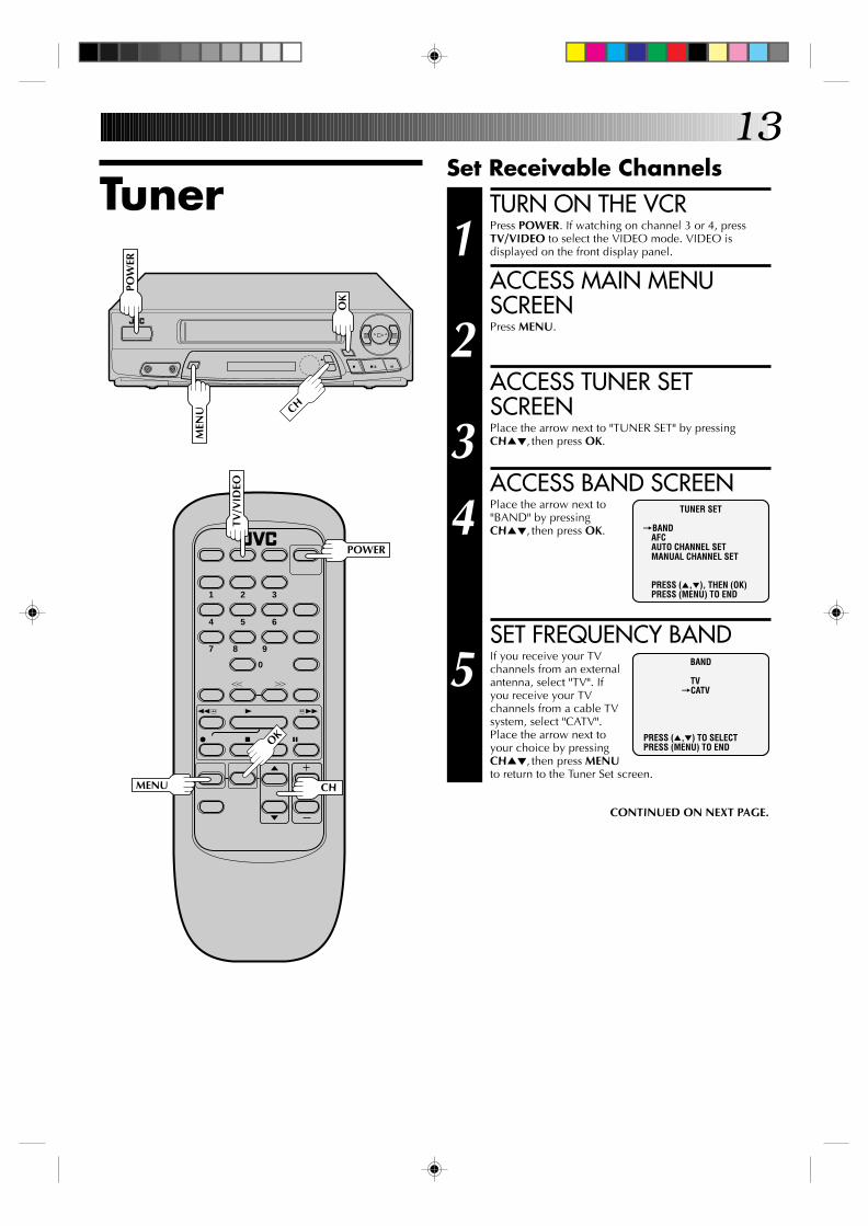
TunerSet Receivable Channels
TURN ON THE VCR
1 Press POWER. If watching on channel 3 or 4, pressTV/VIDEO to select the VIDEO mode. VIDEO isdisplayed on the front display panel.
ACCESS MAIN MENUSCREEN
2 Press MENU.
ACCESS TUNER SETSCREEN
3 Place the arrow next to "TUNER SET" by pressingCH5∞, then press OK.
ACCESS BAND SCREEN
4 Place the arrow next to"BAND" by pressingCH5∞, then press OK.
SET FREQUENCY BAND
5 If you receive your TVchannels from an externalantenna, select "TV". Ifyou receive your TVchannels from a cable TVsystem, select "CATV".Place the arrow next toyour choice by pressingCH5∞, then press MENUto return to the Tuner Set screen.
BAND
TV=CATV
PRESS (5,∞) TO SELECTPRESS (MENU) TO END
TUNER SET
=BANDAFCAUTO CHANNEL SETMANUAL CHANNEL SET
PRESS (5,∞), THEN (OK)PRESS (MENU) TO END
CONTINUED ON NEXT PAGE.
POW
ER
POWER

14PERFORM AUTO CHANNELSET
6 Place the arrow next to"AUTO CHANNEL SET" bypressing CH5∞, thenpress OK. Receivablechannels in your area areautomatically assigned tothe CH5∞ buttons, andnon-receivable channelsare skipped.
NOTES:● At the end of Auto Channel Set, “SCAN COM-
PLETED” appears on screen.● If the scan was unsuccessful, “SCAN COMPLETED–
NO SIGNAL” appears on screen. Check the bandsetting and connections and start again.
RETURN TO NORMALSCREEN
7 Press MENU as many times as necessary.
q
2
3
6
5/8
MEN
U
1 2 3
4 5 6
7 8
0
9
q 65
4
YT
2 3
OK
AUTO CHANNEL SET
(TV)CH 2 ADD
SCANNING ...
PRESS (MENU) TO END
INITIAL SETTINGS (cont.)
CHMENU
OK
CH

15
q
2
3
6
5/8
Add Or Delete A ChannelACCESS TUNER SETSCREEN
1 Access by performing steps 2 and 3 of the Tunerprocedure on page 13.
● To add a channel, go to step 2.● To delete a channel, skip to step 4.
ACCESS AFC SCREEN
2 Place the arrow next to "AFC" by pressing CH5∞, thenpress OK.
MAKE SELECTION
3 Place the arrow next to"SPCL" by pressing CH5∞,then press MENU to returnto the Tuner Set screen.
ACCESS MANUALCHANNEL SET SCREEN
4 Place the arrow next to "MANUAL CHANNEL SET" bypressing CH5∞, then press OK.
STORE DESIRED CHANNEL
5 Input the channel numberusing the NUMBER keys orby pressing CH5∞, thenpress ADD to add orCH.SKIP to delete. Repeatfor each channel you wantto store or skip.
RETURN TO NORMALSCREEN
6 Press MENU as many times as necessary.
1 2 3
4 5 6
7 8
0
9
q 65
4
YT
2 3
CH.SKIP
OK
MENU CH
ADD
AFC
NORM=SPCL
PRESS (5,∞) TO SELECTPRESS (MENU) TO END
MEN
U
OK
CH
NUMBER
MANUAL CHANNEL SET
(CATV)CH 125 SKIP
SELECT CH NO. ANDPRESS (ADD/SKIP)PRESS (MENU) TO END
16 SIMPLE PLAYBACK AND RECORDING
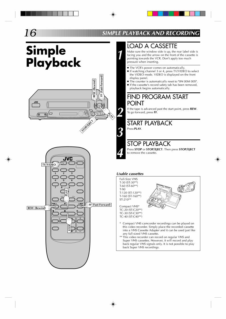
LOAD A CASSETTE
1 Make sure the window side is up, the rear label side isfacing you and the arrow on the front of the cassette ispointing towards the VCR. Don’t apply too muchpressure when inserting.
● The VCR’s power comes on automatically.● If watching channel 3 or 4, press TV/VIDEO to select
the VIDEO mode. VIDEO is displayed on the frontdisplay panel.
● The counter is automatically reset to "0H 00M 00S".● If the cassette's record safety tab has been removed,
playback begins automatically.
FIND PROGRAM STARTPOINT
2 If the tape is advanced past the start point, press REW.To go forward, press FF.
START PLAYBACK
3 Press PLAY.
STOP PLAYBACK
4 Press STOP or STOP/EJECT. Then press STOP/EJECTto remove the cassette.
SimplePlayback
1 2 3
4 5 6
7 8
0
9
q 65
4
YT
2 3
q
2
3
6
5/8
REW
(R
ewin
d)
STOP/
EJECT
FF (
Fast
-For
war
d)
PLAY
STO
PPL
AY
FF (Fast-Forward)REW (Rewind)
TV/VIDEO
Usable cassettesFull-Size VHST-30 (ST-30**)T-60 (ST-60**)T-90T-120 (ST-120**)T-160 (ST-160**)ST-210**
Compact VHS*TC-20 (ST-C20**)TC-30 (ST-C30**)TC-40 (ST-C40**)
* Compact VHS camcorder recordings can be played onthis video recorder. Simply place the recorded cassetteinto a VHS Cassette Adapter and it can be used just likeany full-sized VHS cassette.
** This video recorder can record on regular VHS andSuper VHS cassettes. However, it will record and playback regular VHS signals only. It is not possible to playback Super VHS recordings.
17
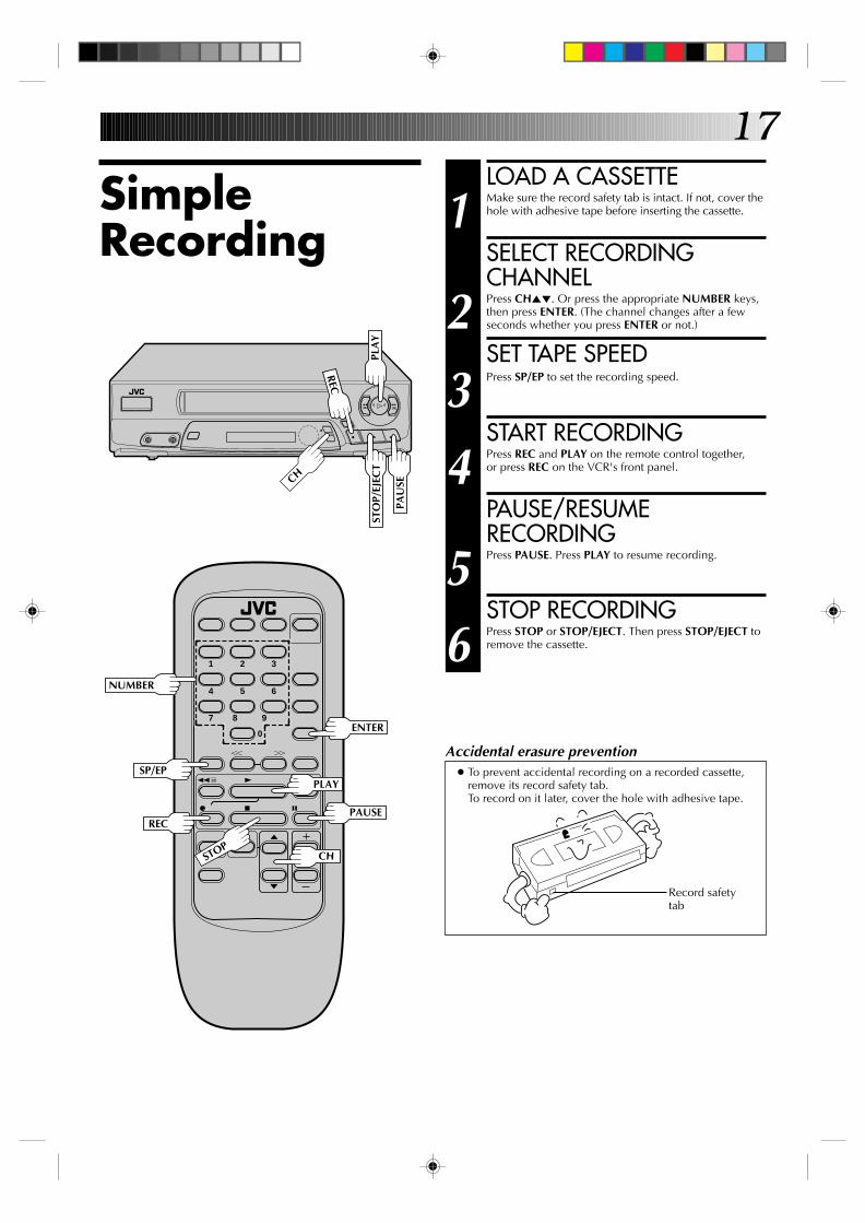
SimpleRecording
LOAD A CASSETTE
1 Make sure the record safety tab is intact. If not, cover thehole with adhesive tape before inserting the cassette.
SELECT RECORDINGCHANNEL
2 Press CH5∞. Or press the appropriate NUMBER keys,then press ENTER. (The channel changes after a fewseconds whether you press ENTER or not.)
SET TAPE SPEED
3 Press SP/EP to set the recording speed.
START RECORDING
4 Press REC and PLAY on the remote control together,or press REC on the VCR's front panel.
PAUSE/RESUMERECORDING
5 Press PAUSE. Press PLAY to resume recording.
STOP RECORDING
6 Press STOP or STOP/EJECT. Then press STOP/EJECT toremove the cassette.
q
2
3
6
5/8
1 2 3
4 5 6
7 8
0
9
q 65
4
YT
2 3
STO
P/EJ
ECT
PAU
SE
REC
SP/EP
REC
STOP
PAUSE
PLAY
Accidental erasure prevention● To prevent accidental recording on a recorded cassette,
remove its record safety tab.To record on it later, cover the hole with adhesive tape.
Record safetytab
NUMBER
PLA
Y
CH
CH
ENTER
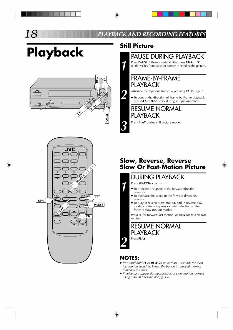
18
PAUSE DURING PLAYBACK
1 Press PAUSE. If there is vertical jitter, press CH5 or ∞on the VCR's front panel or remote to stabilize the picture.
FRAME-BY-FRAMEPLAYBACK
2 Advance the tape one frame by pressing PAUSE again.
● To control the direction of Frame-by-Frame playback,press SEARCH<< or >> during still picture mode.
RESUME NORMALPLAYBACK
3 Press PLAY during still picture mode.
PlaybackStill Picture
1 2 3
4 5 6
7 8
0
9
q 65
4
YT
2 3
q
2
3
6
5/8
PAU
SEPL
AY
CH
PAUSE
PLAY
PLAYBACK AND RECORDING FEATURES
SEARCHT
Y
Slow, Reverse, ReverseSlow Or Fast-Motion Picture
DURING PLAYBACK
1 Press SEARCH<< or >>.
● To increase the speed in the forward direction,press >>.
● To decrease the speed in the forward direction,press <<.
● To play in reverse slow motion, and in reverse playmode, continue to press << after selecting all theforward slow motion modes.
Press FF for forward fast motion, or REW for reverse fastmotion.
RESUME NORMALPLAYBACK
2 Press PLAY.
NOTES:● Press and hold FF or REW for more than 2 seconds for short
fast-motion searches. When the button is released, normalplayback resumes.
● If noise bars appear during playback or slow motion, correctusing manual tracking. (Z pg. 19).
FF
REW
FF REW
CH
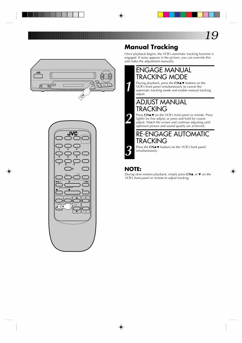
19Manual TrackingOnce playback begins, the VCR’s automatic tracking function isengaged. If noise appears in the picture, you can override thisand make the adjustment manually.
q
2
3
6
5/8
1 2 3
4 5 6
7 8
0
9
q 65
4
YT
2 3
CH
CH
ENGAGE MANUALTRACKING MODE
1 During playback, press the CH5∞ buttons on theVCR's front panel simultaneously to cancel theautomatic tracking mode and enable manual trackingadjust.
ADJUST MANUALTRACKING
2 Press CH5∞ on the VCR's front panel or remote. Presslightly for fine adjust, or press and hold for coarseadjust. Watch the screen and continue adjusting untiloptimum picture and sound quality are achieved.
RE-ENGAGE AUTOMATICTRACKING
3 Press the CH5∞ buttons on the VCR's front panelsimultaneously.
NOTE:During slow-motion playback, simply press CH5 or ∞ on theVCR's front panel or remote to adjust tracking.

20SuperimposeThis function, switchable between ON and OFF, determineswhether or not operational indicators will appear on screen.
ACCESS MAIN MENUSCREEN
1 Press MENU.
ACCESS FUNCTION SETSCREEN
2 Place the arrow next to "FUNCTION SET" bypressing CH5∞, then press OK.
ACCESS SUPERIMPOSESCREEN
3 Place the arrow next to"SUPERIMPOSE" bypressing CH5∞, thenpress OK.
SELECT MODE
4 Place the arrow next to"ON" or "OFF" by pressingCH5∞.
RETURN TO NORMALSCREEN
5 Press MENU as many times as necessary.
NOTE:If you engage the Record Pause mode, RECORD/PAUSE isdisplayed whether "SUPERIMPOSE" is set to "ON" or "OFF".
q
2
3
6
5/8
MEN
U
SUPERIMPOSE
=ONOFF
PRESS (5,∞) TO SELECTPRESS (MENU) TO END
FUNCTION
AUTO TIMER=SUPERIMPOSE
PRESS (5,∞), THEN (OK)PRESS (MENU) TO END
CH
7 8
0
9
q 65
4
YT
2 3
OK
MENU CH
OSD
OK
PLAYBACK AND RECORDING FEATURES (cont.)
"Cassette Loaded" markWhen a cassette is loaded, the mark is
displayed for 5 seconds. It blinks when theVCR's EJECT button is pushed. Counter reading
CH 125 RECORDTHU 12:00 AM PAUSE
] SP
INDEX-1
COUNT –1:23:45
Tuned-in channel or AUX(iliary) modeWhen the channel is changed, the newchannel is displayed on the screen for 5
seconds.Clock time
Tape position indicator
B E+ + +
Tape speed indicator
Operation modeWhen the operation mode is changed,the new mode is displayed — RECORD(5 sec.), PLAY (5 sec.), FF/REW (5 sec.when engaged from Stop mode),RECORD PAUSE (for as long as Pause isengaged), and ITR *:** (5 sec.).
The superimposed indication on the TV screen tells you what the VCR is doing.
INDEX indication
To recall an indication
1 Press OSD.n All indications corresponding to the current status are
displayed for 5 seconds, leaving the counter information,and RECORD/PAUSE if in the Record Pause mode, onthe screen. (No indication during still and search.)
2 Press OSD again to clear the display.

21
q
2
3
6
5/8
1 2 3
4 5 6
7 8
0
9
q 65
4
YT
2 3
STO
P
STOP
SKIP SEARCH
Skip Search
SKIP OVER UNWANTEDSECTIONS
1 Press SKIP SEARCH 1 to 4 times during playback. Eachpress initiates a 30-second period of fast- motionplayback. Normal playback resumes automatically.
NOTE:To return to normal playback during a Skip Search,press PLAY.
Index SearchThis function seeks out index codes that are placed on the tapeat recording start.
START SEARCH
1 While the tape is stopped, press SEARCH << or >>.
ACCESS DISTANT CODE
2 To access a recording 2–9 index codes away, pressSEARCH << or >> repeatedly until the correct numberis displayed on screen (only if SUPERIMPOSE is set toON (Z pg. 20). Playback begins automatically whendesired recording is located.
•To find the very beginning of the desired program, pressREW or FF and search visually for the start point.
VIDEO SP PLAY
H M S
FF
PLAY
REW
SEAR
CH
PLAY
REWFF
Repeat Playback
START REPEAT
1 Press and hold PLAY (until "PLAY" blinks on the frontdisplay panel) during playback, then release.
•The entire tape is played back 20 times.
STOP REPEAT
2 To stop, press STOP at any time.
NOTE:Pressing PLAY, REW, FF or PAUSE also stops RepeatPlayback.
PAUSE
22
1 2 3
4 5 6
7 8
0
9
q 65
4
YT
2 3
q
2
3
6
5/8
POW
ER
PLA
YFF
REW
REWFF
POWER
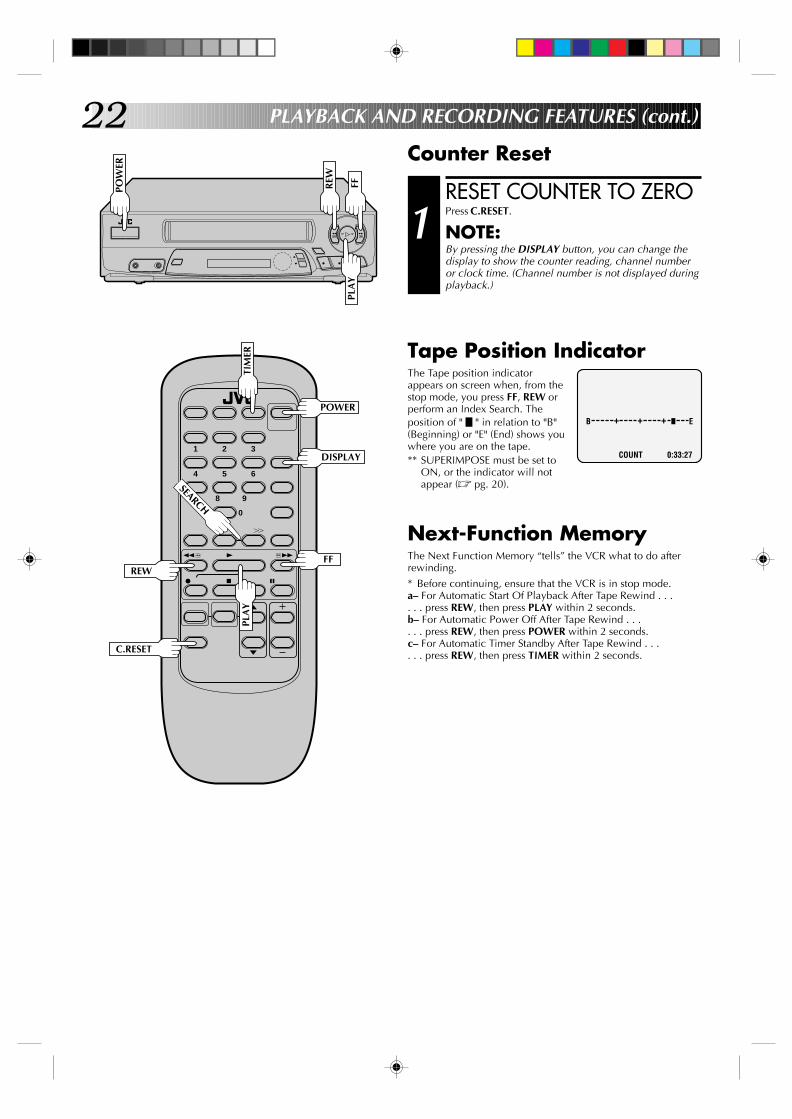
RESET COUNTER TO ZERO
1 Press C.RESET.
NOTE:By pressing the DISPLAY button, you can change thedisplay to show the counter reading, channel numberor clock time. (Channel number is not displayed duringplayback.)
Counter Reset
DISPLAY
C.RESET
COUNT 0:33:27
Tape Position IndicatorThe Tape position indicatorappears on screen when, from thestop mode, you press FF, REW orperform an Index Search. Theposition of " " in relation to "B"(Beginning) or "E" (End) shows youwhere you are on the tape.** SUPERIMPOSE must be set to
ON, or the indicator will notappear (Z pg. 20).
Next-Function MemoryThe Next Function Memory “tells” the VCR what to do afterrewinding.* Before continuing, ensure that the VCR is in stop mode.a– For Automatic Start Of Playback After Tape Rewind . . .. . . press REW, then press PLAY within 2 seconds.b– For Automatic Power Off After Tape Rewind . . .. . . press REW, then press POWER within 2 seconds.c– For Automatic Timer Standby After Tape Rewind . . .. . . press REW, then press TIMER within 2 seconds.
B E+ + +
TIM
ER
PLAYBACK AND RECORDING FEATURES (cont.)
PLA
Y
SEARCH

23
RecordingRecord One Program WhileWatching Another
q
2
3
6
5/8
1 2 3
4 5 6
7 8
0
9
q 65
4
YT
2 3
C.RESET
OSD
TV/V
IDEO
ENGAGE TV MODE
1 During recording...● If using the RF connection (Z pg. 6), press TV/VIDEO.
The VCR's VIDEO indicator goes out and the TVbroadcast being recorded disappears.
● If using the AV connection (Z pg. 6), change theTV's input mode from AV to TV.
SELECT CHANNEL FORVIEWING
2 Use the TV’s channel selector to set the channel youwant to watch.
Display Elapsed RecordingTime
RESET COUNTER TO ZERO
1 Before recording starts, press C.RESET. The counterresets to zero and displays the exact elapsed time as thetape runs.
DISPLAY ELAPSED TIME ONSCREEN
2 During recording, press OSD at any time to see theelapsed time. All indications corresponding to thecurrent status of the VCR are displayed for 5 seconds.The counter display remains on the screen indicating theelapsed time. Press OSD again to remove the display.
● Make sure "SUPERIMPOSE" is set to "ON" (Z pg. 20).

24
Instant TimerRecording(ITR)
This easy method lets you record for from 30 minutes to 6 hours(selectable in 30-min. increments), and shuts the VCR off afterrecording is finished.
START RECORDING
1 Press REC.
ENGAGE ITR MODE
2 Press REC again. ITR blinks and 0:30 appears on thefront display panel.
SET RECORDINGDURATION
3 If you want to record for more than 30 minutes, pressREC to extend the time. Each press extends recordingtime by 30 minutes.
NOTES:● You can only perform ITR using the REC button on the VCR's
front panel.● After you set the time, the previous display reappears.● To check remaining recording time, press REC once during
recording and the remaining time is displayed for about 5seconds. Be careful not to press again during this 5 seconds,or you’ll add 30 more minutes to the recording.
LOAD A CASSETTE
1 Make sure the record safety tab is intact. If not, coverthe hole with adhesive tape, then load.
● The VCR comes on, and the counter is reset,automatically.
ACCESS PROGRAM SETSCREEN
2 Press MENU, then pressOK.
You can directly program the VCR’s timer to record up to 8shows, as far as a year in advance. Remember, the clock mustbe set before you can program the timer (Z pg. 7 or 11).
I T R
VIDEO SPR E C
q
2
3
6
5/8
REC
On-ScreenTimerProgramming* Refer to the illustration on page 25.
PROGRAM 1
DATE - - / - -START - - : - - AMSTOP - - : - - AMCHANNEL - - SP
PRESS NUMBER KEY(0-9)OR (5,∞), THEN (OK)
PRESS (MENU) TO END
TIMER RECORDING

25
q
2
3
6
5/8
MEN
U
1 2 3
4 5 6
7 8
0
9
q 65
4
YT
2 3
OK
OK
MENU CH
CH
TIM
ER
NUMBERNUMBER "9"
NUMBER
"8"
SELECT PROGRAMNUMBER
3 Press the appropriate NUMBER keys or CH5∞ to selecta vacant program number, then press OK. The first timeyou do this, all numbers will be vacant, so just pressOK when the screen appears.
SET PROGRAMINFORMATION
4 Press the appropriate NUMBER keys to set the date,start/stop time and channel number. Press CH5∞ to setAM/PM and tape speed. Then press OK after AM/PM,channel number and tape speed settings. The nextsetting that can be set begins flashing.
● Any information comprised of 1 digit (except thechannel number) should have a "0" entered before it.
● It is possible to set all information using the CH5∞buttons. (In this case, press OK after each setting.)
NOTE:If you are using a cable box, enter the cable boxchannel, not the channel to be recorded. The channelto be recorded must be selected on the cable box. (Thecable box channel is the VCR's channel that displaysthe channels received by the cable box.)
** You can record selected programs at the same timeevery weekday, or once a week. Before entering themonth, press NUMBER key “8” (DAILY) or “9”(WEEKLY). Either "DAILY" or "WEEKLY" appears.Press again and "DAILY" or "WEEKLY" disappears.
MAKE CORRECTIONS
5 To change any of the settings, press OK until the item youwant to change begins blinking. Then set as in step 4.
RETURN TO NORMALSCREEN
6 Press MENU as many times as necessary.
● Press just once to access the Auto Timer screen(Z pg. 27).
ENGAGE TIMER MODE
7 Press TIMER. The VCR turns off automatically.
EXAMPLEIf you program the VCR to timerrecord a show on September 6on channel 40 from 12:00 noonto 1:00 PM in SP mode, thescreen will look like this:
PROGRAM 1
DATE 9/ 6 SUNSTART 12:00 PMSTOP 1:00 PMCHANNEL 40 SP
PRESS NUMBER KEY(0-9)OR (5,∞), THEN (OK)
PRESS (MENU) TO END
NOTES:● To disengage the timer before recording starts, press TIMER
again. Pressing once more re-engages it.● In case of a power failure after programming, the VCR’s
memory backup keeps your selections for 10 minutes.● If you select "PROGRAM SET" without having set the date and
time, an error message appears. Follow its instructions.● If you enter a start time that has already passed, ERROR
appears on the screen and flashes.● Programs that start after midnight must have the next day’s
date.
● After timer recording is completed, the VCR’s power goes offautomatically.
● You can program the timer while a regular recording is inprogress; the on-screen menu will not be recorded.
● If the end of tape is reached during timer recording, thecassette is automatically ejected.
● When timer-recording cable channels received through aCable Box, be sure to keep the Cable Box set to ON.
26
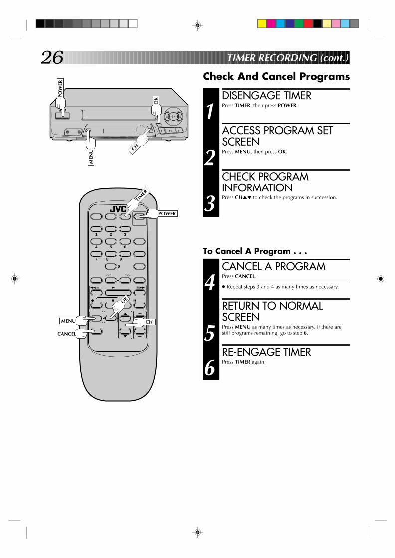
DISENGAGE TIMER
1 Press TIMER, then press POWER.
ACCESS PROGRAM SETSCREEN
2 Press MENU, then press OK.
CHECK PROGRAMINFORMATION
3 Press CH5∞ to check the programs in succession.
Check And Cancel Programs
To Cancel A Program . . .
q
2
3
6
5/8
MEN
U
1 2 3
4 5 6
7 8
0
9
q 65
4
YT
2 3
OK
OK
CHMENU
CH
CANCEL
POW
ER
POWER
TIM
ER
CANCEL A PROGRAM
4 Press CANCEL.
● Repeat steps 3 and 4 as many times as necessary.
RETURN TO NORMALSCREEN
5 Press MENU as many times as necessary. If there arestill programs remaining, go to step 6.
RE-ENGAGE TIMER
6 Press TIMER again.
TIMER RECORDING (cont.)
27
q
2
3
6
5/8
MEN
U
1 2 3
4 5 6
7 8
0
9
q 65
4
YT
2 3
OK
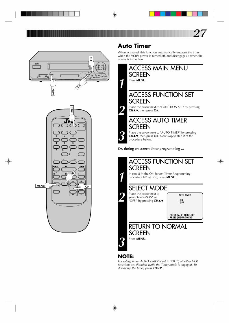
Auto TimerWhen activated, this function automatically engages the timerwhen the VCR's power is turned off, and disengages it when thepower is turned on.
OK
CHMENU
ACCESS MAIN MENUSCREEN
1 Press MENU.
ACCESS FUNCTION SETSCREEN
2 Place the arrow next to "FUNCTION SET" by pressingCH5∞, then press OK.
ACCESS AUTO TIMERSCREEN
3 Place the arrow next to "AUTO TIMER" by pressingCH5∞, then press OK. Now skip to step 2 of theprocedure below.
Or, during on-screen timer programming ...
ACCESS FUNCTION SETSCREEN
1 In step 5 in the On-Screen Timer Programmingprocedure (Z pg. 25), press MENU.
SELECT MODE
2 Place the arrow next toyour choice ("ON" or"OFF") by pressing CH5∞.
RETURN TO NORMALSCREEN
3 Press MENU.
NOTE:For safety, when AUTO TIMER is set to “OFF”, all other VCRfunctions are disabled while the Timer mode is engaged. Todisengage the timer, press TIMER.
AUTO TIMER
=ONOFF
PRESS (5,∞) TO SELECTPRESS (MENU) TO END
CH
TIM
ER

28
Edit To OrFrom AnotherVCR
You can use your VCR as the player or the recorder.
MAKE CONNECTIONS
1 Connect an AV cable (not supplied) between theplayer’s VIDEO OUT and AUDIO OUT connectors andthe recorder’s VIDEO IN and AUDIO IN connectors.
● When connecting to a Hi-Fi VCR, connect yourVCR's AUDIO IN/OUT connector to the AUDIO LIN/OUT connector on the Hi-Fi VCR.
LOAD CASSETTES
2 Insert the playback cassette into the player and thecassette to be recorded on into the recorder.
SET RECORDER’S INPUTMODE
3 Set to AUX. With this VCR, press NUMBER key “0” (AUappears on the front display panel in place of a channelnumber).
START PLAYER
4 Set to its play mode.
START RECORDER
5 Set to its record mode.
Player Your VCR
AUDIO OUT
VIDEO OUT
VIDEO IN AUDIO IN
1 2 3
4 5 6
7 8
0
9
q 65
4
YT
2 3
Another VCRRecorder
NUMBER "0"
EDITING
29
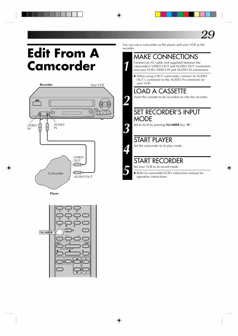
Edit From ACamcorder
You can use a camcorder as the player and your VCR as therecorder.
MAKE CONNECTIONS
1 Connect an AV cable (not supplied) between thecamcorder’s VIDEO OUT and AUDIO OUT connectorsand your VCR’s VIDEO IN and AUDIO IN connectors.
● When using a Hi-Fi camcorder, connect its AUDIOOUT L connector to the AUDIO IN connector onyour VCR.
LOAD A CASSETTE
2 Insert the cassette to be recorded on into the recorder.
SET RECORDER’S INPUTMODE
3 Set to AUX by pressing NUMBER key “0”.
START PLAYER
4 Set the camcorder to its play mode.
START RECORDER
5 Set your VCR to its record mode.
● Refer to camcorder/VCR's instruction manual foroperation instructions.
1 2 3
4 5 6
7 8
0
9
q 65
4
YT
2 3
NUMBER "0"
q
2
3
6
5/8
Recorder Your VCR
Camcorder
Player
VIDEOOUT
VIDEOIN
AUDIOIN
AUDIO OUT

30
1 2 3
4 5 6
7 8
0
9
q 65
4
YT
2 3
Multi-Brand Remote ControlIn addition to controlling several functions on JVC remote controlTVs, the VCR's remote control can control these functions on theTV brands listed below. If your television is a JVC, you don’t haveto set the code in step 1.
SELECT TV BRAND
1 Refer to the chart below. While holding down TV, pressthe Brand Selection Button that corresponds to thebrand of your TV.
● You don’t have to repeat this step until you replacethe remote control’s batteries.
OPERATE TV
2 While holding down TV, press POWER, CH5∞ orTV/VIDEO to control these functions. VOL+/– can beoperated without holding TV down.
● The NUMBER keys cannot be used to set or changethe channel on the TV.
NOTES:● With some televisions, the TV/VIDEO button only functions
to switch the TV to its VIDEO (AV) mode. It may not switchthe TV back to its TV mode.
● Although the provided remote control is compatible with JVCtelevisions as well as many TV models manufactured by othercompanies, it is possible that the provided remote control willnot work with your TV.
TV/V
IDEO
POWER
MENU
CH
OK
FF
PLA
Y
STOP
PAUSE
CANCEL
VOL. +/-
SPECIAL FEATURES
BRANDTV BRANDSELECTIONNAMEBUTTON
REW JVCPLAY MAGNAVOXFF MITSUBISHIREC PANASONICSTOP RCAPAUSE SHARPMENU SONYOK TOSHIBAADD ZENITHCANCEL HITACHI
ADD
TV
REW
REC
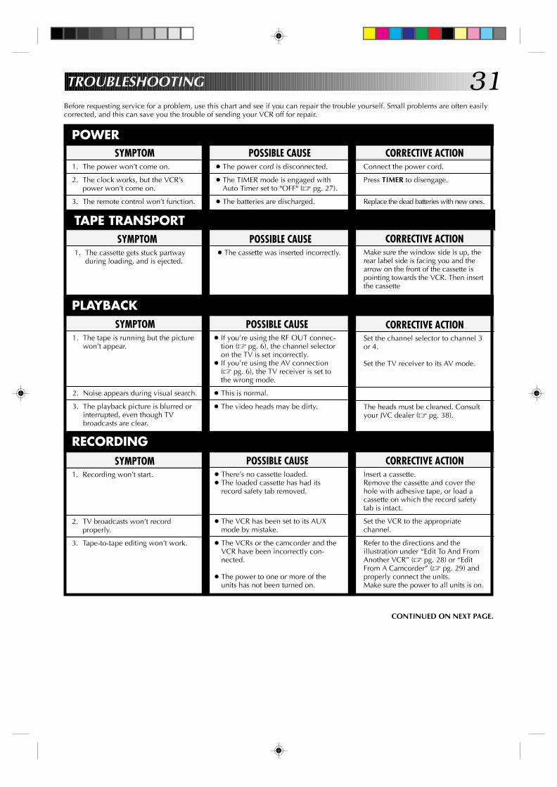
31TROUBLESHOOTING
Before requesting service for a problem, use this chart and see if you can repair the trouble yourself. Small problems are often easilycorrected, and this can save you the trouble of sending your VCR off for repair.
POWERPOSSIBLE CAUSE
● The power cord is disconnected.
● The TIMER mode is engaged withAuto Timer set to "OFF" (Z pg. 27).
● The batteries are discharged.
SYMPTOM1. The power won’t come on.
2. The clock works, but the VCR’spower won’t come on.
3. The remote control won’t function.
CORRECTIVE ACTIONConnect the power cord.
Press TIMER to disengage.
Replace the dead batteries with new ones.
TAPE TRANSPORTPOSSIBLE CAUSE
● The cassette was inserted incorrectly.
SYMPTOM1. The cassette gets stuck partway
during loading, and is ejected.
CORRECTIVE ACTIONMake sure the window side is up, therear label side is facing you and thearrow on the front of the cassette ispointing towards the VCR. Then insertthe cassette
SYMPTOM1. The tape is running but the picture
won’t appear.
2. Noise appears during visual search.
3. The playback picture is blurred orinterrupted, even though TVbroadcasts are clear.
PLAYBACKPOSSIBLE CAUSE
● If you’re using the RF OUT connec-tion (Z pg. 6), the channel selectoron the TV is set incorrectly.
● If you’re using the AV connection(Z pg. 6), the TV receiver is set tothe wrong mode.
● This is normal.
● The video heads may be dirty.
CORRECTIVE ACTIONSet the channel selector to channel 3or 4.
Set the TV receiver to its AV mode.
The heads must be cleaned. Consultyour JVC dealer (Z pg. 38).
CORRECTIVE ACTIONInsert a cassette.Remove the cassette and cover thehole with adhesive tape, or load acassette on which the record safetytab is intact.
Set the VCR to the appropriatechannel.
Refer to the directions and theillustration under “Edit To And FromAnother VCR” (Z pg. 28) or “EditFrom A Camcorder” (Z pg. 29) andproperly connect the units.Make sure the power to all units is on.
POSSIBLE CAUSE● There’s no cassette loaded.● The loaded cassette has had its
record safety tab removed.
● The VCR has been set to its AUXmode by mistake.
● The VCRs or the camcorder and theVCR have been incorrectly con-nected.
● The power to one or more of theunits has not been turned on.
SYMPTOM1. Recording won’t start.
2. TV broadcasts won’t recordproperly.
3. Tape-to-tape editing won’t work.
RECORDING
CONTINUED ON NEXT PAGE.

32TIMER RECORDING
CORRECTIVE ACTIONCheck or re-perform the clock/timersettings to ensure correctness.Press TIMER and check to make surethat TIMER appears on the frontdisplay panel.Re-perform the set-up procedures.
Timer programming can’t be performedwhen timer recording is in progress.Wait until it finishes.
Load a cassette with the record safetytab intact, or with the hole coveredwith adhesive tape.
Remove the cassette and cover itshole with adhesive tape, or replace itwith a cassette on which the safetytab is intact.
Check the programmed data and re-program as necessary, then pressTIMER again.
The program may not have beenrecorded in its entirety. Next timemake sure you have enough time onthe tape to record the entire program.
SYMPTOM1. Timer recording won’t work.
2. On-screen timer programmingwon’t work.
3. TIMER and ] on the frontdisplay panel won’t stop blinking.
4. The cassette is automaticallyejected, and TIMER and ] on thefront display panel won’t stopblinking.
5. TIMER blinks for 10 seconds andthe timer mode is disengaged.
6. The cassette is automaticallyejected, the power shuts off andTIMER and ] won’t stopblinking.
POSSIBLE CAUSE● The clock and/or the timer have
been set incorrectly.● The timer is not engaged.
● The VCR has not been set up properly.
● Timer recording is in progress.
● The timer is engaged but there’s nocassette loaded.
● The loaded cassette has had itsrecord safety tab removed.
● TIMER has been pressed when thereare no programs in memory, or thetimer record program informationhas not been programmed correctly.
● The end of tape was reached duringtimer recording.
ATTENTION:This recorder contains microcomputers. External electronic noise or interference could cause malfunctioning. In such cases,switch the power off and unplug the power cord. Then plug it in again and switch power on. Take out the cassette. Afterchecking the cassette, operate the unit as usual.
TROUBLESHOOTING (cont.)
OTHER PROBLEMSCORRECTIVE ACTION
If you need the skipped channels,restore them (Z pg. 15).
Press PAUSE to pause the recording,change channels, then press PLAY toresume recording.
Select a different Host Channel duringthe Semi-Auto setting procedure(Z pg. 9), or perform the Manualsetting procedure (Z pg. 10).
SYMPTOM1. When scanning channels, some of
them are skipped over.
2. The channel can’t be changed.
3. (HR-A42U only) Even though Autoor Semi-Auto clock setting hasbeen selected, the clock isincorrect.
POSSIBLE CAUSE● Those channels have been preset to
be skipped.
● Recording is in progress.
● The clock setting data received fromthe Host Channel is incorrect.
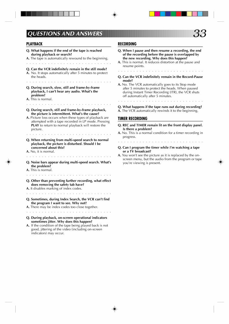
33QUESTIONS AND ANSWERS
PLAYBACKQ. What happens if the end of the tape is reached
during playback or search?
○ ○ ○ ○ ○ ○ ○ ○ ○ ○ ○ ○ ○ ○ ○ ○ ○ ○ ○ ○ ○ ○ ○ ○ ○ ○ ○ ○
A. The tape is automatically rewound to the beginning.
Q. Can the VCR indefinitely remain in the still mode?A. No. It stops automatically after 5 minutes to protect
○ ○ ○ ○ ○ ○ ○ ○ ○ ○ ○ ○ ○ ○ ○ ○ ○ ○ ○ ○ ○ ○ ○ ○ ○ ○ ○ ○
the heads.
Q. During search, slow, still and frame-by-frameplayback, I can’t hear any audio. What’s theproblem?
○ ○ ○ ○ ○ ○ ○ ○ ○ ○ ○ ○ ○ ○ ○ ○ ○ ○ ○ ○ ○ ○ ○ ○ ○ ○ ○ ○
A. This is normal.
Q. During search, still and frame-by-frame playback,the picture is intermittent. What’s the cause?
A. Picture loss occurs when these types of playback areattempted with a tape recorded in LP mode. PressingPLAY to return to normal playback will restore the
○ ○ ○ ○ ○ ○ ○ ○ ○ ○ ○ ○ ○ ○ ○ ○ ○ ○ ○ ○ ○ ○ ○ ○ ○ ○ ○ ○
picture.
Q. When returning from multi-speed search to normalplayback, the picture is disturbed. Should I beconcerned about this?
○ ○ ○ ○ ○ ○ ○ ○ ○ ○ ○ ○ ○ ○ ○ ○ ○ ○ ○ ○ ○ ○ ○ ○ ○ ○ ○ ○
A. No, it is normal.
Q. Noise bars appear during multi-speed search. What’sthe problem?
○ ○ ○ ○ ○ ○ ○ ○ ○ ○ ○ ○ ○ ○ ○ ○ ○ ○ ○ ○ ○ ○ ○ ○ ○ ○ ○ ○
A. This is normal.
Q. Other than preventing further recording, what effectdoes removing the safety tab have?
○ ○ ○ ○ ○ ○ ○ ○ ○ ○ ○ ○ ○ ○ ○ ○ ○ ○ ○ ○ ○ ○ ○ ○ ○ ○ ○ ○
A. It disables marking of index codes.
Q. Sometimes, during Index Search, the VCR can’t findthe program I want to see. Why not?
○ ○ ○ ○ ○ ○ ○ ○ ○ ○ ○ ○ ○ ○ ○ ○ ○ ○ ○ ○ ○ ○ ○ ○ ○ ○ ○ ○
A. There may be index codes too close together.
Q. During playback, on-screen operational indicatorssometimes jitter. Why does this happen?
A. If the condition of the tape being played back is notgood, jittering of the video (including on-screenindicators) may occur.
RECORDINGQ. When I pause and then resume a recording, the end
of the recording before the pause is overlapped bythe new recording. Why does this happen?
A. This is normal. It reduces distortion at the pause and
○ ○ ○ ○ ○ ○ ○ ○ ○ ○ ○ ○ ○ ○ ○ ○ ○ ○ ○ ○ ○ ○ ○ ○ ○ ○ ○ ○
resume points.
Q. Can the VCR indefinitely remain in the Record-Pausemode?
A. No. The VCR automatically goes to its Stop modeafter 5 minutes to protect the heads. When pausedduring Instant Timer Recording (ITR), the VCR shuts
○ ○ ○ ○ ○ ○ ○ ○ ○ ○ ○ ○ ○ ○ ○ ○ ○ ○ ○ ○ ○ ○ ○ ○ ○ ○ ○ ○
off automatically after 5 minutes.
Q. What happens if the tape runs out during recording?A. The VCR automatically rewinds it to the beginning.
TIMER RECORDINGQ. REC and TIMER remain lit on the front display panel.
Is there a problem?A. No. This is a normal condition for a timer recording in
○ ○ ○ ○ ○ ○ ○ ○ ○ ○ ○ ○ ○ ○ ○ ○ ○ ○ ○ ○ ○ ○ ○ ○ ○ ○ ○ ○
progress.
Q. Can I program the timer while I’m watching a tapeor a TV broadcast?
A. You won’t see the picture as it is replaced by the on-screen menu, but the audio from the program or tapeyou’re viewing is present.

34TIMERClock reference : QuartzProgram capacity : 1-year programmable timer/
8 programsMemory backup time : Approx. 10 min.
ACCESSORIESProvided accessories : RF cable (F-type),
Infrared remote control unit,“AA” battery x 2
SPECIFICATIONS
GENERALPower requirement : AC 120 V` , 60 HzPower consumption : 19 WTemperature
Operating : 5°C to 40°C (41°F to 104°F)Storage : –20°C to 60°C (–4°F to140°F)
Operating position : Horizontal onlyDimensions (W x H x D) : 360 x 94 x 276 mm
(14-3/16" x 3-3/4" x 10-7/8")Weight : 3.4 kg (7.5 lbs)Format : VHS NTSC standardMaximum recording time
SP : 210 min. with ST-210 videocassette
EP : 630 min. with ST-210 videocassette
VIDEO/AUDIOSignal system : NTSC-type color signal and
EIA monochrome signal, 525lines/60 fields
Recording/Playback system : HR-A42U
DA-4 (Double Azimuth) headhelical scan systemHR-A22URotary two-head helical scansystem
Signal-to-noise ratio : 45 dBHorizontal resolution : 240 linesFrequency range : 70 Hz to 10,000 HzInput/Output : RCA connectors
(IN x 1, OUT x 1)
TUNERTuning system : Frequency-synthesized tunerChannel coverage
VHF : Channels 2–13UHF : Channels 14–69CATV : 113 Channels
RF output : Channel 3 or 4 (switchable;preset to Channel 3 whenshipped) 75 ohms,unbalanced
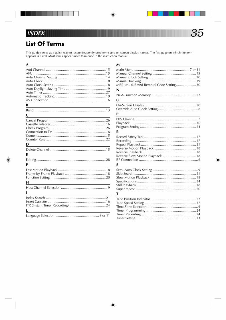
35INDEX
List Of TermsThis guide serves as a quick way to locate frequently used terms and on-screen display names. The first page on which the termappears is listed. Most terms appear more than once in the instruction manual.
AAdd Channel ...............................................................15AFC.............................................................................15Auto Channel Setting ..................................................14Auto Clock ....................................................................8Auto Clock Setting ........................................................8Auto Daylight Saving Time ............................................9Auto Timer ..................................................................27Automatic Tracking .....................................................19AV Connection .............................................................6
BBand ...........................................................................13
CCancel Program ..........................................................26Cassette Adapter.................................... ......................16Check Program ...........................................................26Connection to TV ..........................................................6Contents ........................................................................5Counter Reset ..............................................................22
DDelete Channel ...........................................................15
EEditing.........................................................................28
FFast Motion Playback ..................................................18Frame-by-Frame Playback ...........................................18Function Setting ..........................................................20
HHost Channel Selection .................................................9
IIndex Search ...............................................................21Insert Cassette .............................................................16ITR (Instant Timer Recording) ......................................24
LLanguage Selection .............................................. 8 or 11
MMain Menu .......................................................... 7 or 11Manual Channel Setting ..............................................15Manual Clock Setting ..................................................10Manual Tracking .........................................................19MBR (Multi-Brand Remote) Code Setting .....................30
NNext-Function Memory ...............................................22
OOn-Screen Display ......................................................20Override Auto Clock Setting ..........................................8
PPBS Channel .................................................................7Playback .....................................................................16Program Setting ...........................................................24
RRecord Safety Tab .......................................................17Recording ...................................................................17Repeat Playback..........................................................21Reverse Motion Playback ............................................18Reverse Playback ........................................................18Reverse Slow Motion Playback ...................................18RF Connection ..............................................................6
SSemi-Auto Clock Setting ................................................9Skip Search .................................................................21Slow Motion Playback ................................................18Specifications ..............................................................34Still Playback ..............................................................18Superimpose ...............................................................20
TTape Position Indicator ................................................22Tape Speed Setting ......................................................17Time Zone Selection .....................................................9Timer Programming.....................................................24Timer Recording..........................................................24Tuner Setting ...............................................................13
36 INDEX (cont.)
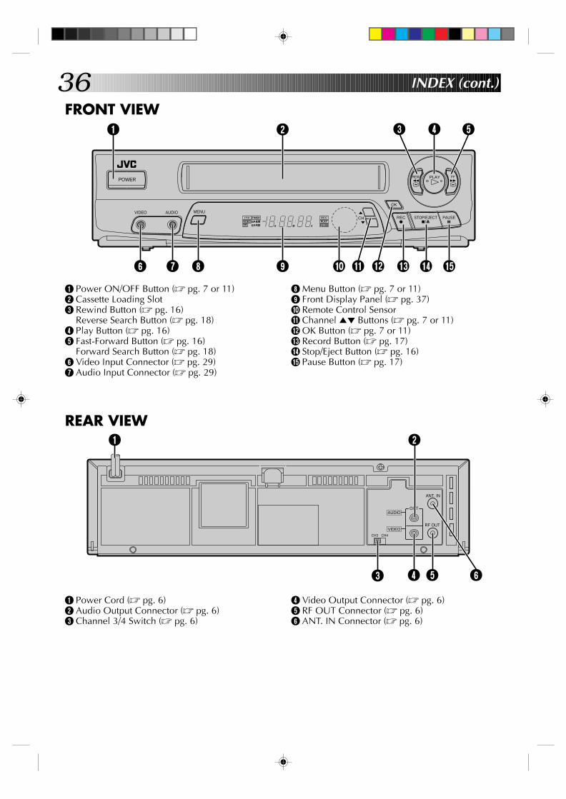
FRONT VIEW
POWER
MENUVIDEO AUDIOCH
OK
REC q
PLAY
REW 2
FF 3
PAUSE 6
STOP/EJECT 5/8
H M S
I T R TIMER
VIDEO SPEP
AMPM
R E C
PAUSEPLAY
1
9 0 ! @ # $ %
2 3 4 5
6 7 8
1 Power ON/OFF Button (Z pg. 7 or 11)2 Cassette Loading Slot3 Rewind Button (Z pg. 16)
Reverse Search Button (Z pg. 18)4 Play Button (Z pg. 16)5 Fast-Forward Button (Z pg. 16)
Forward Search Button (Z pg. 18)6 Video Input Connector (Z pg. 29)7 Audio Input Connector (Z pg. 29)
8 Menu Button (Z pg. 7 or 11)9 Front Display Panel (Z pg. 37)0 Remote Control Sensor! Channel 5∞ Buttons (Z pg. 7 or 11)@ OK Button (Z pg. 7 or 11)# Record Button (Z pg. 17)$ Stop/Eject Button (Z pg. 16)% Pause Button (Z pg. 17)
REAR VIEW
1 Power Cord (Z pg. 6)2 Audio Output Connector (Z pg. 6)3 Channel 3/4 Switch (Z pg. 6)
4 Video Output Connector (Z pg. 6)5 RF OUT Connector (Z pg. 6)6 ANT. IN Connector (Z pg. 6)
ANT. IN
RF OUT
CH3 CH4
OUTAUDIO
VIDEO
1 2
3 4 5 6

37FRONT DISPLAY PANEL
1 Video Mode Indicator (Z pg. 7 or 11)2 Instant Timer Recording Indicator (Z pg. 24)3 Timer Mode Indicator (Z pg. 25)4 Clock Display (Z pg. 7)5 Counter Display (Z pg. 22)6 Recording Mode Indicator (Z pg. 17)7 Play Mode Indicator (Z pg. 16)
8 “Cassette Loaded” Mark9 Tape Speed Indicators (Z pg. 17)0 AM/PM Indicators (Z pg. 7)! Channel Display [“AU” for AUX mode]
(Z pg. 28)@ Pause Mode Indicator (Z pg. 17)
REMOTE CONTROL (Provided)
TV TV/VIDEO TIMER
DISPLAY
ADD
ENTER
SP/EP
1 2 3
4 5 6
7 8
0
9
TV VOL.CH
MENU OK
CANCEL
q REC 6 PAUSE5 STOP
4PLAY FF 32 REW
SKIP SEARCHT SEARCH Y
DAILY WEEKLY
C.RESET/ CH.SKIP
TV operation – Press and hold TV button, then press POWER, CH 5/∞, TV/VIDEO
AUX
OSD
POWER
56
3
2
1
4
7890!@#$
%
^
&*()qwe
r
t
y
1 TV/VIDEO Button (Z pg. 7 or 11)2 TV Operation Button (Z pg. 30)(Refer to y below)3 NUMBER Buttons (Z pg. 10 or 12)4 WEEKLY Timer Recording Button (Z pg. 25)5 DAILY Timer Recording Button (Z pg. 25)6 “AUX” Mode Select Button (Z pg. 28)7 Reverse/Forward SEARCH Buttons (Z pg. 18)8 Recording Speed [SP/EP] Button (Z pg. 17)9 Rewind [REW] Button (Z pg. 16)0 PLAY Button (Z pg. 16)! Record [REC] Button (Z pg. 17)@ MENU Button (Z pg. 7 or 11)# OK Button (Z pg. 7 or 11)$ CANCEL Button (Z pg. 26)
Counter [C.] RESET (Z pg. 22)Channel [CH.] SKIP Button (Z pg. 15)
% TIMER Button (Z pg. 25)^ POWER ON/OFF Button (Z pg. 7 or 11)& DISPLAY Button (Z pg. 22)* ADD Button (Z pg. 15)( ENTER Button (Z pg. 17)
On-Screen Display [OSD] Button (Z pg. 20)) SKIP SEARCH Button (Z pg. 21)q Fast-Forward [FF] Button (Z pg. 16)w STOP Button (Z pg. 16)e PAUSE Button (Z pg. 17)r Volume [VOL] +/– Buttons (Z pg. 30)t Channel [CH] 5∞ Buttons (Z pg. 7 or 11)y Instructions for remote control of the following
TV functions: POWER, CH 5∞ and TV/VIDEOswitching.
H M S
I T R TIMER
VIDEO SPEP
AMPM
R E C
PAUSEPLAY
1
8 9 0 ! @
2 3 4 5 6 7
38HOW TO LOCATE YOUR JVC SERVICE CENTER
TOLL FREE: 1-800-252-5722
JVC SERVICE & ENGINEERINGCOMPANY OF AMERICA
DIVISION OF US JVC CORP.
FACTORY SERVICE CENTER LOCATIONS
If you ship the product...
ACCESSORIES
107 Little Falls Road 1500 Lakes Parkway 705 Enterprise StreetFairfield, NJ 07004-2105 Lawrenceville, GA 30243-5357 Aurora, IL 60504-8149(201) 808-9279 (770) 339-2522 (708) 851-7855
5665 Corporate Avenue 10700 Hammerly, Suite 110 2969 Mapunapuna PlaceCypress, CA 90630-0024 Houston, TX 77043-2310 Honolulu, HI 96819-2040(714) 229-8011 (713) 935-9331 (808) 833-5828
230 Eliot Street 14505 Commerce Way 890 Dubuque AvenueAshland, MA 01721-2377 Miami Lakes, FL 33016-1512 South San Francisco, CA 94080-1804(508) 881-5923 (305) 362-6252 (415) 871-2666
Sophisticated electronic products may require occasional service. Just as quality is a keyword in the engineering and productionof the wide array of JVC products, service is the key to maintaining the high level performance for which JVC is world famous. TheJVC service and engineering organization stands behind our products.
NATIONAL HEADQUARTERSJVC SERVICE & ENGINEERING COMPANY OF AMERICA
DIVISION OF US JVC CORP.107 Little Falls Road
Fairfield, NJ 07004-2105
Pack your JVC unit in the original carton or one of equivalentsize and strength. Enclose, with the unit, a letter stating theproblem or symptom that exists and also a copy of the receiptor bill of sale you received when you purchased your JVCunit. Print your home return address on the outside and theinside of the carton. Send to the appropriate JVC FactoryService Center as listed above.
To purchase accessories for your JVC product, you maycontact your local JVC Dealer.Or from the 48 Continental United States call toll free:1-800-882-2345.
Dear customer:In order to receive the most satisfaction from your purchase, read the instruction booklet before operating the unit. In the eventthat repair is necessary, or for the address nearest your location, please refer to the factory service center list below or within theContinental United States, call 1-800-252-5722 for your authorized servicer. Remember to retain your Bill of Sale for WarrantyService.
— JVC
CAUTIONTo prevent electrical shock, do not open the cabinet. No userserviceable parts inside.Refer servicing to qualified service personnel.
Don't service it yourself.
FOR SERVICING

39
LIMITED WARRANTY CONSUMER VIDEO 1-90
JVC COMPANY OF AMERICA warrants this product and all parts thereof, except as set forth below ONLY TO THE ORIGINALPURCHASER AT RETAIL to be FREE FROM DEFECTIVE MATERIALS AND WORKMANSHIP from the date of original retailpurchase for the period as shown below. ("The Warranty Period")
THIS LIMITED WARRANTY IS VALID ONLY IN THE FIFTY (50) UNITED STATES, THE DISTRICT OF COLUMBIA AND INCOMMONWEALTH OF PUERTO RICO.
WHAT WE WILL DO:If this product is found to be defective, JVC will repair or replace defective parts at no charge to the original owner. Such repairand replacement services shall be rendered by JVC during normal business hours at JVC authorized service centers. Partsused for replacement are warranted only for the remainder of the Warranty Period. All products and parts thereof may bebrought to a JVC authorized service center on a carry-in basis except for Television sets having a screen size 25 inches andabove which are covered on an in-home basis.
WHAT YOU MUST DO FOR WARRANTY SERVICE:Return your product to a JVC authorized service center with a copy of your bill of sale. For your nearest JVC authorizedservice center, please call toll free: (800) 252-5722.
If service is not available locally, box the product carefully, preferably in the original carton, and ship, insured, with a copy ofyour bill of sale plus a letter of explanation of the problem to the nearest JVC Factory Service Center, the name and locationof which will be given to you by the toll-free number.
If you have any questions concerning your JVC Product, please contact our Customer Relations Department.
WHAT IS NOT COVERED:This limited warranty provided by JVC does not cover:1. Products which have been subject to abuse, accident, alteration, modification, tampering, negligence, misuse, faulty
installation, lack of reasonable care, or if repaired or serviced by anyone other than a service facility authorized by JVC torender such service, or if affixed to any attachment not provided with the products, or if the model or serial number has beenaltered, tampered with, defaced or removed;
2. Initial installation and installation and removal for repair;3. Operational adjustments covered in the Owner's Manual, normal maintenance, video and audio head cleaning;4. Damage that occurs in shipment, due to act of God, and cosmetic damage;5. Signal reception problems and failures due to line power surge;6. Video Pick-up Tubes/CCD Image Sensor, Cartridge, Stylus (Needle) are covered for 90 days from the date of purchase;7. Accessories;8. Batteries (except that Rechargeable Batteries are covered for 90 days from the date of purchase); from the date of purchase);
There are no other express warranties except as listed above.
THE DURATION OF ANY IMPLIED WARRANTIES INCLUDING THE IMPLIED WARRANTY OF MERCHANTABILITY, ISLIMITED TO THE DURATION OF THE EXPRESS WARRANTY HEREIN.
JVC SHALL NOT BE LIABLE FOR THE LOSS OF USE OF THE PRODUCT, INCONVENIENCE, LOSS OR ANY OTHERDAMAGES, WHETHER DIRECT, INCIDENTAL OR CONSEQUENTIAL (INCLUDING, WITHOUT LIMITATION, DAMAGE TOTAPES, RECORDS OR DISCS) RESULTING FROM THE USE OF THIS PRODUCT, OR ARISING OUT OF ANY BREACHOF THIS WARRANTY. ALL EXPRESS AND IMPLIED WARRANTIES, INCLUDING THE WARRANTIES OFMERCHANTABILITY AND FITNESS FOR PARTICULAR PURPOSE, ARE LIMITED TO THE WARRANTY PERIOD SETFORTH ABOVE.
Some states do not allow the exclusion of incidental or consequential dameges or limitations on how long an implied warrantylasts, so these limitations or exclusions may not apply to you. This warranty gives you specific legal rights and you may alsohave other rights which vary from state to state.
JVC COMPANY OF AMERICA 41 Slater DriveDIVISION OF US JVC CORP. Elmwood Park, New Jersey 07407
REFURBISHED PRODUCTS CARRY A SEPARATE WARRANTY, THIS WARRANTY DOES NOT APPLY. FOR DETAILS OFREFURBISHED PRODUCT WARRANTY, PLEASE REFER TO THE REFURBISHED PRODUCT WARRANTY INFORMATIONPACKAGED WITH EACH REFURBISHED PRODUCT.
For customer use:Enter below the Model No. and Serial No. which is located either on the rear, bottom or side of the cabinet. Retain this information for futurereference.
Model No.: Serial No.:
Purchase date: Name of dealer:
PARTS LABOR1 YR 90 DAYS
WARRANTY

HR
-A4
2/A
22
U
COPYRIGHT © 1996 VICTOR COMPANY OF JAPAN, LTD. U Printed in Malaysia 0196YOV*UN*PJ
JVC COMPANY OF AMERICA DIVISION OF US JVC CORP.
41 Slater Drive, Elmwood Park, N.J. 07407