Junos® OS Circuit Emulation Interfaces Feature Guide for ... · event(CFM) ......
244
Junos ® OS Circuit Emulation Interfaces Feature Guide for Routing Devices Modified: 2018-03-13 Copyright © 2018, Juniper Networks, Inc.
Transcript of Junos® OS Circuit Emulation Interfaces Feature Guide for ... · event(CFM) ......
Junos®OS
Circuit Emulation Interfaces Feature Guide forRouting Devices
Modified: 2018-03-13
Copyright © 2018, Juniper Networks, Inc.

Juniper Networks, Inc.1133 InnovationWaySunnyvale, California 94089USA408-745-2000www.juniper.net
Juniper Networks, the Juniper Networks logo, Juniper, and Junos are registered trademarks of Juniper Networks, Inc. and/or its affiliates inthe United States and other countries. All other trademarks may be property of their respective owners.
Juniper Networks assumes no responsibility for any inaccuracies in this document. Juniper Networks reserves the right to change, modify,transfer, or otherwise revise this publication without notice.
Junos®OS Circuit Emulation Interfaces Feature Guide for Routing Devices
Copyright © 2018 Juniper Networks, Inc. All rights reserved.
The information in this document is current as of the date on the title page.
YEAR 2000 NOTICE
Juniper Networks hardware and software products are Year 2000 compliant. Junos OS has no known time-related limitations through theyear 2038. However, the NTP application is known to have some difficulty in the year 2036.
ENDUSER LICENSE AGREEMENT
The Juniper Networks product that is the subject of this technical documentation consists of (or is intended for use with) Juniper Networkssoftware. Use of such software is subject to the terms and conditions of the End User License Agreement (“EULA”) posted athttps://www.juniper.net/support/eula/. By downloading, installing or using such software, you agree to the terms and conditions of thatEULA.
Copyright © 2018, Juniper Networks, Inc.ii

Table of Contents
About the Documentation . . . . . . . . . . . . . . . . . . . . . . . . . . . . . . . . . . . . . . . . . . . . xi
Documentation and Release Notes . . . . . . . . . . . . . . . . . . . . . . . . . . . . . . . . . . xi
Supported Platforms . . . . . . . . . . . . . . . . . . . . . . . . . . . . . . . . . . . . . . . . . . . . . xi
Using the Examples in This Manual . . . . . . . . . . . . . . . . . . . . . . . . . . . . . . . . . . xi
Merging a Full Example . . . . . . . . . . . . . . . . . . . . . . . . . . . . . . . . . . . . . . . xii
Merging a Snippet . . . . . . . . . . . . . . . . . . . . . . . . . . . . . . . . . . . . . . . . . . . . xii
Documentation Conventions . . . . . . . . . . . . . . . . . . . . . . . . . . . . . . . . . . . . . . xiii
Documentation Feedback . . . . . . . . . . . . . . . . . . . . . . . . . . . . . . . . . . . . . . . . . xv
Requesting Technical Support . . . . . . . . . . . . . . . . . . . . . . . . . . . . . . . . . . . . . xv
Self-Help Online Tools and Resources . . . . . . . . . . . . . . . . . . . . . . . . . . . xv
Opening a Case with JTAC . . . . . . . . . . . . . . . . . . . . . . . . . . . . . . . . . . . . . xvi
Part 1 Overview
Chapter 1 Understanding Circuit Emulation Interfaces . . . . . . . . . . . . . . . . . . . . . . . . . . . 3
Understanding Circuit Emulation Services and the Supported PIC Types . . . . . . . . 3
4-Port Channelized OC3/STM1 (Multi-Rate) Circuit Emulation MIC with
SFP . . . . . . . . . . . . . . . . . . . . . . . . . . . . . . . . . . . . . . . . . . . . . . . . . . . . . . . . 4
12-Port Channelized T1/E1 Circuit Emulation PIC . . . . . . . . . . . . . . . . . . . . . . . . 5
8-Port OC3/STM1 or 12-port OC12/STM4 ATM MIC . . . . . . . . . . . . . . . . . . . . . 6
16-Port Channelized E1/T1 Circuit Emulation MIC . . . . . . . . . . . . . . . . . . . . . . . 6
Layer 2 Circuit Standards . . . . . . . . . . . . . . . . . . . . . . . . . . . . . . . . . . . . . . . . . . 7
Understanding Circuit Emulation PIC Clocking Features . . . . . . . . . . . . . . . . . . . . . 8
Understanding ATM QoS or Shaping . . . . . . . . . . . . . . . . . . . . . . . . . . . . . . . . . . . . 9
Chapter 2 Understanding HowCircuit Emulation Interfaces Support ConvergedNetworks That Accommodate Both IP And Legacy Services . . . . . . . . . . . . 13
Understanding Mobile Backhaul . . . . . . . . . . . . . . . . . . . . . . . . . . . . . . . . . . . . . . . 13
Mobile Backhaul Application Overview . . . . . . . . . . . . . . . . . . . . . . . . . . . . . . 13
IP/MPLS-based Mobile Backhaul . . . . . . . . . . . . . . . . . . . . . . . . . . . . . . . . . . . 14
Part 2 Configuring Circuit Emulation Interfaces
Chapter 3 Configuring SAToP Support on Circuit Emulation PICs . . . . . . . . . . . . . . . . . 19
Configuring SAToP on 4-Port Channelized OC3/STM1 Circuit Emulation
MICs . . . . . . . . . . . . . . . . . . . . . . . . . . . . . . . . . . . . . . . . . . . . . . . . . . . . . . . . . . 19
Configuring SONET/SDH Rate-Selectability . . . . . . . . . . . . . . . . . . . . . . . . . . 19
Configuring SONET/SDH Framing Mode at the MIC Level . . . . . . . . . . . . . . . 20
iiiCopyright © 2018, Juniper Networks, Inc.
Configuring SONET/SDH Framing Mode at the Port Level . . . . . . . . . . . . . . . 20
Configuring SAToP Options on T1 interfaces . . . . . . . . . . . . . . . . . . . . . . . . . . . 21
Configuring COC3 Ports Down to T1 Channels . . . . . . . . . . . . . . . . . . . . . 21
Configuring SAToP Options on a T1 interface . . . . . . . . . . . . . . . . . . . . . . 22
Configuring SAToP Options on E1 Interfaces . . . . . . . . . . . . . . . . . . . . . . . . . . 23
Configuring CSTM1 Ports Down to E1 Channels . . . . . . . . . . . . . . . . . . . . 24
Configuring SAToP Options on E1 Interfaces . . . . . . . . . . . . . . . . . . . . . . . 25
Configuring SAToP Emulation on T1/E1 Interfaces on 12-Port Channelized T1/E1
Circuit Emulation PICs . . . . . . . . . . . . . . . . . . . . . . . . . . . . . . . . . . . . . . . . . . . 26
Setting the Emulation Mode . . . . . . . . . . . . . . . . . . . . . . . . . . . . . . . . . . . . . . . 26
Configuring SAToP Emulation on T1/E1 Interfaces . . . . . . . . . . . . . . . . . . . . . . 26
Setting the Encapsulation Mode . . . . . . . . . . . . . . . . . . . . . . . . . . . . . . . . 27
Configuring Loopback for a T1 Interface or an E1 Interface . . . . . . . . . . . . 27
Setting the SAToP Options . . . . . . . . . . . . . . . . . . . . . . . . . . . . . . . . . . . . 27
Configuring the Pseudowire Interface . . . . . . . . . . . . . . . . . . . . . . . . . . . . 29
Setting the SAToP Options . . . . . . . . . . . . . . . . . . . . . . . . . . . . . . . . . . . . . . . . . . . 30
Chapter 4 Configuring SAToP Support on Circuit Emulation MICs . . . . . . . . . . . . . . . . . 33
Configuring SAToP on 16-Port Channelized E1/T1 Circuit Emulation MIC . . . . . . . 33
Configuring T1/E1 Framing Mode at the MIC Level . . . . . . . . . . . . . . . . . . . . . . 33
Configuring CT1 Ports Down to T1 Channels . . . . . . . . . . . . . . . . . . . . . . . . . . 34
Configuring CT1 Ports Down to DS Channels . . . . . . . . . . . . . . . . . . . . . . . . . . 35
Configuring SAToP Encapsulation on T1/E1 Interfaces . . . . . . . . . . . . . . . . . . . . . . 36
Setting the Encapsulation Mode . . . . . . . . . . . . . . . . . . . . . . . . . . . . . . . . . . . 36
T1/E1 Loopback Support . . . . . . . . . . . . . . . . . . . . . . . . . . . . . . . . . . . . . . . . . . 36
T1 FDL Support . . . . . . . . . . . . . . . . . . . . . . . . . . . . . . . . . . . . . . . . . . . . . . . . . 37
Setting the SAToP Options . . . . . . . . . . . . . . . . . . . . . . . . . . . . . . . . . . . . . . . . 37
Configuring the Pseudowire Interface . . . . . . . . . . . . . . . . . . . . . . . . . . . . . . . 38
Chapter 5 Configuring CESoPSN Support on Circuit Emulation MIC . . . . . . . . . . . . . . . 41
Configuring CESoPSN on Channelized E1/T1 Circuit Emulation MIC . . . . . . . . . . . 41
Configuring T1/E1 Framing Mode at the MIC Level . . . . . . . . . . . . . . . . . . . . . . 41
Configuring CT1 Interface Down to DS Channels . . . . . . . . . . . . . . . . . . . . . . . 42
Setting the CESoPSN Options . . . . . . . . . . . . . . . . . . . . . . . . . . . . . . . . . . . . . 43
Configuring CESoPSN on DS Interfaces . . . . . . . . . . . . . . . . . . . . . . . . . . . . . . 44
ConfiguringCESoPSNonChannelizedOC3/STM1 (Multi-Rate)Circuit Emulation
MIC with SFP . . . . . . . . . . . . . . . . . . . . . . . . . . . . . . . . . . . . . . . . . . . . . . . . . . . 45
Configuring SONET/SDH Rate-Selectability . . . . . . . . . . . . . . . . . . . . . . . . . . 45
Configuring SONET/SDH Framing Mode at the MIC Level . . . . . . . . . . . . . . . 46
Configuring CESoPSN Encapsulation on DS Interfaces on CT1 Channels . . . 46
Configuring COC3 Ports Down to CT1 Channels . . . . . . . . . . . . . . . . . . . . 47
Configuring CT1 Channels Down to DS Interfaces . . . . . . . . . . . . . . . . . . 48
Configuring CESoPSN on DS Interfaces . . . . . . . . . . . . . . . . . . . . . . . . . . 49
Configuring CESoPSN Encapsulation on DS Interfaces on CE1 Channels . . . 50
Configuring CSTM1 Ports Down to CE1 Channels . . . . . . . . . . . . . . . . . . . 50
Configuring CSTM4 Ports Down to CE1 Channels . . . . . . . . . . . . . . . . . . . 51
Configuring CE1 Channels Down to DS Interfaces . . . . . . . . . . . . . . . . . . 52
Configuring CESoPSN on DS Interfaces . . . . . . . . . . . . . . . . . . . . . . . . . . 53
Copyright © 2018, Juniper Networks, Inc.iv
Circuit Emulation Interfaces Feature Guide for Routing Devices

Configuring CESoPSN Encapsulation on DS Interfaces . . . . . . . . . . . . . . . . . . . . . 54
Setting the Encapsulation Mode . . . . . . . . . . . . . . . . . . . . . . . . . . . . . . . . . . . 54
Setting the CESoPSN Options . . . . . . . . . . . . . . . . . . . . . . . . . . . . . . . . . . . . . 55
Configuring the Pseudowire Interface . . . . . . . . . . . . . . . . . . . . . . . . . . . . . . . 57
Chapter 6 Configuring ATM Support on Circuit Emulation PICs . . . . . . . . . . . . . . . . . . . 59
ATM Support on Circuit Emulation PICs Overview . . . . . . . . . . . . . . . . . . . . . . . . . 59
ATM OAM Support . . . . . . . . . . . . . . . . . . . . . . . . . . . . . . . . . . . . . . . . . . . . . . 60
Protocol and Encapsulation Support . . . . . . . . . . . . . . . . . . . . . . . . . . . . . . . 60
Scaling Support . . . . . . . . . . . . . . . . . . . . . . . . . . . . . . . . . . . . . . . . . . . . . . . . . 61
Limitations to ATM Support on Circuit Emulation PICs . . . . . . . . . . . . . . . . . . 61
Configuring the 4-Port Channelized COC3/STM1 Circuit Emulation PIC . . . . . . . . 62
T1/E1 Mode Selection . . . . . . . . . . . . . . . . . . . . . . . . . . . . . . . . . . . . . . . . . . . . 62
Configuring a Port for SONET or SDHMode on a 4-Port Channelized
COC3/STM1 Circuit Emulation PIC . . . . . . . . . . . . . . . . . . . . . . . . . . . . . . 63
Configuring an ATM Interface on a Channelized OC1 interface . . . . . . . . . . . . 64
Configuring the 12-Port Channelized T1/E1 Circuit Emulation PIC . . . . . . . . . . . . . 64
Configuring CT1/CE1 Interfaces . . . . . . . . . . . . . . . . . . . . . . . . . . . . . . . . . . . . 65
Configuring T1/E1 Mode at the PIC level . . . . . . . . . . . . . . . . . . . . . . . . . . 65
Creating an ATM Interface on a CT1 or CE1 . . . . . . . . . . . . . . . . . . . . . . . . 65
Creating an ATM Interface on a CE1 Interface . . . . . . . . . . . . . . . . . . . . . 66
Configuring Interface-Specific Options . . . . . . . . . . . . . . . . . . . . . . . . . . . . . . 66
Configuring ATM Interface-Specific Options . . . . . . . . . . . . . . . . . . . . . . 66
Configuring E1 Interface-Specific Options . . . . . . . . . . . . . . . . . . . . . . . . 67
Configuring T1 Interface-Specific Options . . . . . . . . . . . . . . . . . . . . . . . . 67
Understanding Inverse Multiplexing for ATM . . . . . . . . . . . . . . . . . . . . . . . . . . . . . 68
Understanding Asynchronous Transfer Mode . . . . . . . . . . . . . . . . . . . . . . . . . 69
Understanding Inverse Multiplexing for ATM . . . . . . . . . . . . . . . . . . . . . . . . . . 69
How Inverse Multiplexing for ATMWorks . . . . . . . . . . . . . . . . . . . . . . . . . . . . . 69
Supported Platforms . . . . . . . . . . . . . . . . . . . . . . . . . . . . . . . . . . . . . . . . . . . . . 71
ATM IMA Configuration Overview . . . . . . . . . . . . . . . . . . . . . . . . . . . . . . . . . . . . . . 72
IMA Version . . . . . . . . . . . . . . . . . . . . . . . . . . . . . . . . . . . . . . . . . . . . . . . . . . . . 73
IMA Frame Length . . . . . . . . . . . . . . . . . . . . . . . . . . . . . . . . . . . . . . . . . . . . . . . 73
Transmit Clock . . . . . . . . . . . . . . . . . . . . . . . . . . . . . . . . . . . . . . . . . . . . . . . . . . 73
IMA Group Symmetry . . . . . . . . . . . . . . . . . . . . . . . . . . . . . . . . . . . . . . . . . . . . 73
Minimum Active Links . . . . . . . . . . . . . . . . . . . . . . . . . . . . . . . . . . . . . . . . . . . . 74
State Transition Variables: Alpha, Beta, and Gamma . . . . . . . . . . . . . . . . . . . 74
IMA Link Addition and Deletion . . . . . . . . . . . . . . . . . . . . . . . . . . . . . . . . . . . . 74
IMA Test Pattern Procedure . . . . . . . . . . . . . . . . . . . . . . . . . . . . . . . . . . . . . . . 75
Per-PIC Limit on the Number of Links . . . . . . . . . . . . . . . . . . . . . . . . . . . . . . . 75
IMA Group Alarms and Group Defects . . . . . . . . . . . . . . . . . . . . . . . . . . . . . . . 76
IMA Link Alarms and Link Defects . . . . . . . . . . . . . . . . . . . . . . . . . . . . . . . . . . . 77
IMA Group Statistics . . . . . . . . . . . . . . . . . . . . . . . . . . . . . . . . . . . . . . . . . . . . . 78
IMA Link Statistics . . . . . . . . . . . . . . . . . . . . . . . . . . . . . . . . . . . . . . . . . . . . . . . 78
IMA Clocking . . . . . . . . . . . . . . . . . . . . . . . . . . . . . . . . . . . . . . . . . . . . . . . . . . . 79
Differential Delay . . . . . . . . . . . . . . . . . . . . . . . . . . . . . . . . . . . . . . . . . . . . . . . . 79
Configuring ATM IMA . . . . . . . . . . . . . . . . . . . . . . . . . . . . . . . . . . . . . . . . . . . . . . . . 79
Creating an IMA Group (ATM Interfaces) . . . . . . . . . . . . . . . . . . . . . . . . . . . . 80
Configuring Group ID for an IMA Link on a T1 Interface or an E1 Interface . . . 80
vCopyright © 2018, Juniper Networks, Inc.
Table of Contents
Configuring ATM Encapsulation Options . . . . . . . . . . . . . . . . . . . . . . . . . . . . . 81
Configuring IMA Group Options . . . . . . . . . . . . . . . . . . . . . . . . . . . . . . . . . . . . 81
Configuring ATM Pseudowires . . . . . . . . . . . . . . . . . . . . . . . . . . . . . . . . . . . . . . . . . 82
Cell Relay Mode . . . . . . . . . . . . . . . . . . . . . . . . . . . . . . . . . . . . . . . . . . . . . . . . 83
Configuring VP or Port Promiscuous Mode . . . . . . . . . . . . . . . . . . . . . . . 83
Configuring AAL5 SDU Mode . . . . . . . . . . . . . . . . . . . . . . . . . . . . . . . . . . . . . . 84
Configuring ATM Cell-Relay Pseudowire . . . . . . . . . . . . . . . . . . . . . . . . . . . . . . . . 84
Configuring ATM Cell-Relay Pseudowire in Port-Promiscuous Mode . . . . . . 85
Configuring ATM Cell-Relay Pseudowire in VP-Promiscuous Mode . . . . . . . . 85
Configuring ATM Cell-Relay Pseudowire in VCC Mode . . . . . . . . . . . . . . . . . . 86
ATM Cell Relay Pseudowire VPI/VCI Swapping Overview . . . . . . . . . . . . . . . . . . . 88
Configuring ATM Cell-Relay Pseudowire VPI/VCI Swapping . . . . . . . . . . . . . . . . . 89
Configuring VPI Swapping on Egress and Ingress on ATMMICs . . . . . . . . . . . 89
Configuring Egress Swapping on ATM MICs . . . . . . . . . . . . . . . . . . . . . . . . . . . 91
Disabling Swapping on Local and Remote Provider Edge Routers . . . . . . . . . 93
Configuring Layer 2 Circuit and Layer 2 VPN Pseudowires . . . . . . . . . . . . . . . . . . . 95
Configuring EPD Threshold . . . . . . . . . . . . . . . . . . . . . . . . . . . . . . . . . . . . . . . . . . . 95
Configuring ATM QoS or Shaping . . . . . . . . . . . . . . . . . . . . . . . . . . . . . . . . . . . . . . 96
Part 3 Troubleshooting Information
Chapter 7 Troubleshooting Circuit Emulation Interfaces . . . . . . . . . . . . . . . . . . . . . . . . 101
Displaying Information About Circuit Emulation PICs . . . . . . . . . . . . . . . . . . . . . . 101
Configuring Interface Diagnostics Tools to Test the Physical Layer
Connections . . . . . . . . . . . . . . . . . . . . . . . . . . . . . . . . . . . . . . . . . . . . . . . . . . . 101
Configuring Loopback Testing . . . . . . . . . . . . . . . . . . . . . . . . . . . . . . . . . . . . . 102
Configuring BERT Testing . . . . . . . . . . . . . . . . . . . . . . . . . . . . . . . . . . . . . . . . 104
Starting and Stopping a BERT Test . . . . . . . . . . . . . . . . . . . . . . . . . . . . . . . . 107
Part 4 Configuration Statements and Operational Commands
Chapter 8 Configuration Statements . . . . . . . . . . . . . . . . . . . . . . . . . . . . . . . . . . . . . . . . . . 111
cesopsn-options . . . . . . . . . . . . . . . . . . . . . . . . . . . . . . . . . . . . . . . . . . . . . . . . . . . 112
event (CFM) . . . . . . . . . . . . . . . . . . . . . . . . . . . . . . . . . . . . . . . . . . . . . . . . . . . . . . . 113
fast-aps-switch . . . . . . . . . . . . . . . . . . . . . . . . . . . . . . . . . . . . . . . . . . . . . . . . . . . . 114
ima-group-options . . . . . . . . . . . . . . . . . . . . . . . . . . . . . . . . . . . . . . . . . . . . . . . . . 115
ima-link-options . . . . . . . . . . . . . . . . . . . . . . . . . . . . . . . . . . . . . . . . . . . . . . . . . . . 117
no-vpivci-swapping . . . . . . . . . . . . . . . . . . . . . . . . . . . . . . . . . . . . . . . . . . . . . . . . . 117
payload-size . . . . . . . . . . . . . . . . . . . . . . . . . . . . . . . . . . . . . . . . . . . . . . . . . . . . . . 118
psn-vci (ATM CCC Cell-Relay Promiscuous Mode VPI/VCI Swapping) . . . . . . . . 118
psn-vpi (ATM CCC Cell-Relay Promiscuous Mode VPI/VCI Swapping) . . . . . . . . 119
satop-options . . . . . . . . . . . . . . . . . . . . . . . . . . . . . . . . . . . . . . . . . . . . . . . . . . . . . 120
Chapter 9 Operational Commands . . . . . . . . . . . . . . . . . . . . . . . . . . . . . . . . . . . . . . . . . . . 123
show interfaces (ATM) . . . . . . . . . . . . . . . . . . . . . . . . . . . . . . . . . . . . . . . . . . . . . . 124
show interfaces (T1, E1, or DS) . . . . . . . . . . . . . . . . . . . . . . . . . . . . . . . . . . . . . . . . 159
show interfaces extensive . . . . . . . . . . . . . . . . . . . . . . . . . . . . . . . . . . . . . . . . . . . 184
Copyright © 2018, Juniper Networks, Inc.vi
Circuit Emulation Interfaces Feature Guide for Routing Devices
List of Figures
Part 1 Overview
Chapter 1 Understanding Circuit Emulation Interfaces . . . . . . . . . . . . . . . . . . . . . . . . . . . 3
Figure 1: Two ATM Networks with QoS Shaping and Pseudowire Connection . . . . 10
Figure 2: VC Mapping with Circuit Emulation PICs . . . . . . . . . . . . . . . . . . . . . . . . . 10
Chapter 2 Understanding HowCircuit Emulation Interfaces Support ConvergedNetworks That Accommodate Both IP And Legacy Services . . . . . . . . . . . . 13
Figure 3: Mobile Backhaul Application . . . . . . . . . . . . . . . . . . . . . . . . . . . . . . . . . . . 14
Figure 4:Mobile Backhaul Application onMXSeries RouterswithATMMICswith
SFP . . . . . . . . . . . . . . . . . . . . . . . . . . . . . . . . . . . . . . . . . . . . . . . . . . . . . . . . . . . 14
Part 2 Configuring Circuit Emulation Interfaces
Chapter 6 Configuring ATM Support on Circuit Emulation PICs . . . . . . . . . . . . . . . . . . . 59
Figure 5: 4-Port Channelized COC3/STM1 Circuit Emulation PIC Possible
Interfaces (T1 Size) . . . . . . . . . . . . . . . . . . . . . . . . . . . . . . . . . . . . . . . . . . . . . . 63
Figure 6: 4-Port Channelized COC3/STM1 Circuit Emulation PIC Possible
Interfaces (E1 Size) . . . . . . . . . . . . . . . . . . . . . . . . . . . . . . . . . . . . . . . . . . . . . . 63
Figure 7: 12-Port T1/E1 Circuit Emulation PIC Possible Interfaces (T1 Size) . . . . . . 64
Figure 8: 12-Port T1/E1 Circuit Emulation PIC Possible Interfaces (E1 Size) . . . . . . 64
Figure 9: IMA Frames on Links . . . . . . . . . . . . . . . . . . . . . . . . . . . . . . . . . . . . . . . . . 70
Figure 10: IMA Frames Transmitted Through IMA Group . . . . . . . . . . . . . . . . . . . . 70
Figure 11: ATM Cell Relay Pseudowire VPI/VCI Swapping . . . . . . . . . . . . . . . . . . . 88
viiCopyright © 2018, Juniper Networks, Inc.

Copyright © 2018, Juniper Networks, Inc.viii
Circuit Emulation Interfaces Feature Guide for Routing Devices
List of Tables
About the Documentation . . . . . . . . . . . . . . . . . . . . . . . . . . . . . . . . . . . . . . . . . . xi
Table 1: Notice Icons . . . . . . . . . . . . . . . . . . . . . . . . . . . . . . . . . . . . . . . . . . . . . . . . . xiii
Table 2: Text and Syntax Conventions . . . . . . . . . . . . . . . . . . . . . . . . . . . . . . . . . . xiv
Part 1 Overview
Chapter 1 Understanding Circuit Emulation Interfaces . . . . . . . . . . . . . . . . . . . . . . . . . . . 3
Table 3: Valid EXP Bit Combinations . . . . . . . . . . . . . . . . . . . . . . . . . . . . . . . . . . . . 10
Part 2 Configuring Circuit Emulation Interfaces
Chapter 6 Configuring ATM Support on Circuit Emulation PICs . . . . . . . . . . . . . . . . . . . 59
Table 4: Maximum Number of VCs . . . . . . . . . . . . . . . . . . . . . . . . . . . . . . . . . . . . . 61
Table 5: IMA Frame Synchronization Link State Transition Variables . . . . . . . . . . . 74
Table 6: IMA Group Alarms with IMA Standard Requirement Numbers . . . . . . . . 76
Table 7: IMA Group Defects with IMA Standard Requirement Numbers . . . . . . . . 76
Table 8: IMA Link Alarms with IMA Standard Requirement Numbers . . . . . . . . . . 77
Table 9: IMA Link Defects with IMA Standard Requirement Numbers . . . . . . . . . . 77
Table 10: IMA Link Statistics with IMA Standard Requirement Numbers . . . . . . . . 78
Part 3 Troubleshooting Information
Chapter 7 Troubleshooting Circuit Emulation Interfaces . . . . . . . . . . . . . . . . . . . . . . . . 101
Table 11: Loopback Modes by Interface Type . . . . . . . . . . . . . . . . . . . . . . . . . . . . . 103
Table 12: BERT Capabilities by Interface Type . . . . . . . . . . . . . . . . . . . . . . . . . . . . 106
Part 4 Configuration Statements and Operational Commands
Chapter 9 Operational Commands . . . . . . . . . . . . . . . . . . . . . . . . . . . . . . . . . . . . . . . . . . . 123
Table 13: ATM show interfaces Output Fields . . . . . . . . . . . . . . . . . . . . . . . . . . . . 125
Table 14: T1 or E1 show interfaces Output Fields . . . . . . . . . . . . . . . . . . . . . . . . . . 160
ixCopyright © 2018, Juniper Networks, Inc.

Copyright © 2018, Juniper Networks, Inc.x
Circuit Emulation Interfaces Feature Guide for Routing Devices

About the Documentation
• Documentation and Release Notes on page xi
• Supported Platforms on page xi
• Using the Examples in This Manual on page xi
• Documentation Conventions on page xiii
• Documentation Feedback on page xv
• Requesting Technical Support on page xv
Documentation and Release Notes
To obtain the most current version of all Juniper Networks®technical documentation,
see the product documentation page on the Juniper Networks website at
https://www.juniper.net/documentation/.
If the information in the latest release notes differs from the information in the
documentation, follow the product Release Notes.
Juniper Networks Books publishes books by Juniper Networks engineers and subject
matter experts. These books go beyond the technical documentation to explore the
nuances of network architecture, deployment, and administration. The current list can
be viewed at https://www.juniper.net/books.
Supported Platforms
For the features described in this document, the following platforms are supported:
• MSeries
• MXSeries
Using the Examples in This Manual
If you want to use the examples in this manual, you can use the loadmerge or the load
merge relative command. These commands cause the software to merge the incoming
configuration into the current candidate configuration. The example does not become
active until you commit the candidate configuration.
If the example configuration contains the top level of the hierarchy (or multiple
hierarchies), the example is a full example. In this case, use the loadmerge command.
xiCopyright © 2018, Juniper Networks, Inc.
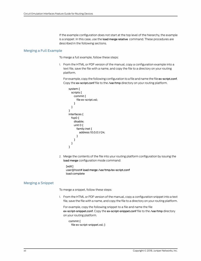
If the example configuration does not start at the top level of the hierarchy, the example
is a snippet. In this case, use the loadmerge relative command. These procedures are
described in the following sections.
Merging a Full Example
Tomerge a full example, follow these steps:
1. From the HTML or PDF version of the manual, copy a configuration example into a
text file, save the file with a name, and copy the file to a directory on your routing
platform.
For example, copy the following configuration toa file andname the file ex-script.conf.
Copy the ex-script.conf file to the /var/tmp directory on your routing platform.
system {scripts {commit {file ex-script.xsl;
}}
}interfaces {fxp0 {disable;unit 0 {family inet {address 10.0.0.1/24;
}}
}}
2. Merge the contents of the file into your routing platform configuration by issuing the
loadmerge configuration mode command:
[edit]user@host# loadmerge /var/tmp/ex-script.confload complete
Merging a Snippet
Tomerge a snippet, follow these steps:
1. From the HTML or PDF version of themanual, copy a configuration snippet into a text
file, save the file with a name, and copy the file to a directory on your routing platform.
For example, copy the following snippet to a file and name the file
ex-script-snippet.conf. Copy the ex-script-snippet.conf file to the /var/tmp directory
on your routing platform.
commit {file ex-script-snippet.xsl; }
Copyright © 2018, Juniper Networks, Inc.xii
Circuit Emulation Interfaces Feature Guide for Routing Devices
2. Move to the hierarchy level that is relevant for this snippet by issuing the following
configuration mode command:
[edit]user@host# edit system scripts[edit system scripts]
3. Merge the contents of the file into your routing platform configuration by issuing the
loadmerge relative configuration mode command:
[edit system scripts]user@host# loadmerge relative /var/tmp/ex-script-snippet.confload complete
For more information about the load command, see CLI Explorer.
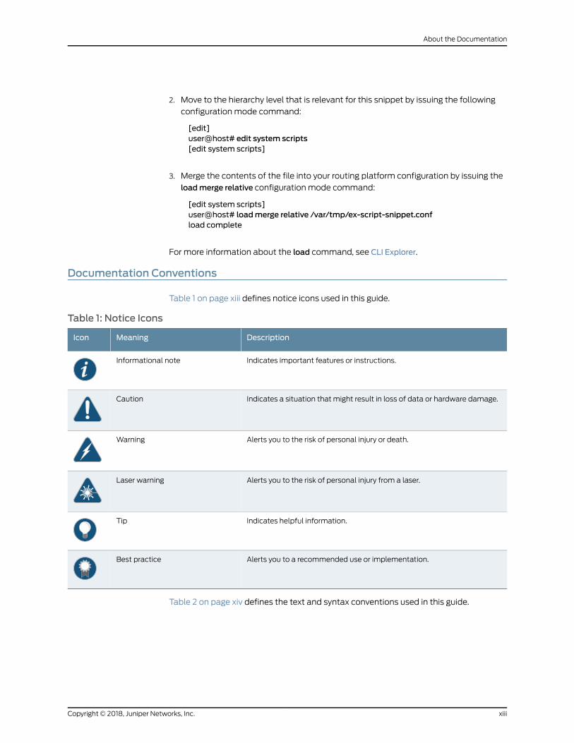
Documentation Conventions
Table 1 on page xiii defines notice icons used in this guide.
Table 1: Notice Icons
DescriptionMeaningIcon
Indicates important features or instructions.Informational note
Indicates a situation that might result in loss of data or hardware damage.Caution
Alerts you to the risk of personal injury or death.Warning
Alerts you to the risk of personal injury from a laser.Laser warning
Indicates helpful information.Tip
Alerts you to a recommended use or implementation.Best practice
Table 2 on page xiv defines the text and syntax conventions used in this guide.
xiiiCopyright © 2018, Juniper Networks, Inc.
About the Documentation
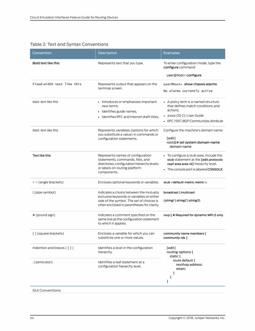
Table 2: Text and Syntax Conventions
ExamplesDescriptionConvention
To enter configuration mode, type theconfigure command:
user@host> configure
Represents text that you type.Bold text like this
user@host> show chassis alarms
No alarms currently active
Represents output that appears on theterminal screen.
Fixed-width text like this
• A policy term is a named structurethat defines match conditions andactions.
• Junos OS CLI User Guide
• RFC 1997,BGPCommunities Attribute
• Introduces or emphasizes importantnew terms.
• Identifies guide names.
• Identifies RFC and Internet draft titles.
Italic text like this
Configure themachine’s domain name:
[edit]root@# set system domain-namedomain-name
Represents variables (options for whichyou substitute a value) in commands orconfiguration statements.
Italic text like this
• To configure a stub area, include thestub statement at the [edit protocolsospf area area-id] hierarchy level.
• Theconsoleport is labeledCONSOLE.
Represents names of configurationstatements, commands, files, anddirectories; configurationhierarchy levels;or labels on routing platformcomponents.
Text like this
stub <default-metricmetric>;Encloses optional keywords or variables.< > (angle brackets)
broadcast | multicast
(string1 | string2 | string3)
Indicates a choice between themutuallyexclusive keywords or variables on eitherside of the symbol. The set of choices isoften enclosed in parentheses for clarity.
| (pipe symbol)
rsvp { # Required for dynamicMPLS onlyIndicates a comment specified on thesame lineas theconfiguration statementto which it applies.
# (pound sign)
community namemembers [community-ids ]
Encloses a variable for which you cansubstitute one or more values.
[ ] (square brackets)
[edit]routing-options {static {route default {nexthop address;retain;
}}
}
Identifies a level in the configurationhierarchy.
Indention and braces ( { } )
Identifies a leaf statement at aconfiguration hierarchy level.
; (semicolon)
GUI Conventions
Copyright © 2018, Juniper Networks, Inc.xiv
Circuit Emulation Interfaces Feature Guide for Routing Devices
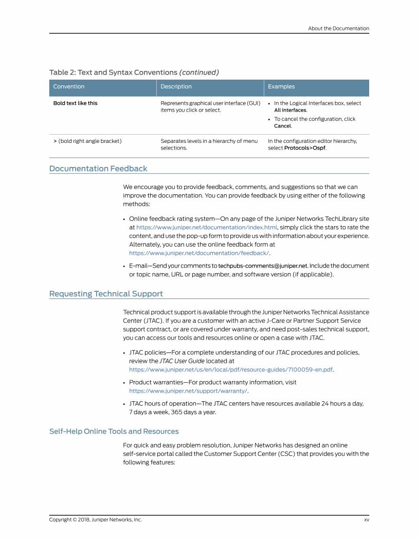
Table 2: Text and Syntax Conventions (continued)
ExamplesDescriptionConvention
• In the Logical Interfaces box, selectAll Interfaces.
• To cancel the configuration, clickCancel.
Representsgraphicaluser interface(GUI)items you click or select.
Bold text like this
In the configuration editor hierarchy,select Protocols>Ospf.
Separates levels in a hierarchy of menuselections.
> (bold right angle bracket)
Documentation Feedback
We encourage you to provide feedback, comments, and suggestions so that we can
improve the documentation. You can provide feedback by using either of the following
methods:
• Online feedback rating system—On any page of the Juniper Networks TechLibrary site
at https://www.juniper.net/documentation/index.html, simply click the stars to rate the
content, anduse thepop-up formtoprovideuswith informationabout your experience.
Alternately, you can use the online feedback form at
https://www.juniper.net/documentation/feedback/.
• E-mail—Sendyourcommentsto [email protected]. Includethedocument
or topic name, URL or page number, and software version (if applicable).
Requesting Technical Support
Technical product support is available through the JuniperNetworksTechnicalAssistance
Center (JTAC). If you are a customer with an active J-Care or Partner Support Service
support contract, or are covered under warranty, and need post-sales technical support,
you can access our tools and resources online or open a case with JTAC.
• JTAC policies—For a complete understanding of our JTAC procedures and policies,
review the JTAC User Guide located at
https://www.juniper.net/us/en/local/pdf/resource-guides/7100059-en.pdf.
• Product warranties—For product warranty information, visit
https://www.juniper.net/support/warranty/.
• JTAC hours of operation—The JTAC centers have resources available 24 hours a day,
7 days a week, 365 days a year.
Self-Help Online Tools and Resources
For quick and easy problem resolution, Juniper Networks has designed an online
self-service portal called the Customer Support Center (CSC) that provides youwith the
following features:
xvCopyright © 2018, Juniper Networks, Inc.
About the Documentation

• Find CSC offerings: https://www.juniper.net/customers/support/
• Search for known bugs: https://prsearch.juniper.net/
• Find product documentation: https://www.juniper.net/documentation/
• Find solutions and answer questions using our Knowledge Base: https://kb.juniper.net/
• Download the latest versions of software and review release notes:
https://www.juniper.net/customers/csc/software/
• Search technical bulletins for relevant hardware and software notifications:
https://kb.juniper.net/InfoCenter/
• Join and participate in the Juniper Networks Community Forum:
https://www.juniper.net/company/communities/
• Open a case online in the CSC Case Management tool: https://www.juniper.net/cm/
Toverify serviceentitlementbyproduct serial number, useourSerialNumberEntitlement
(SNE) Tool: https://entitlementsearch.juniper.net/entitlementsearch/
Opening a Casewith JTAC
You can open a case with JTAC on theWeb or by telephone.
• Use the Case Management tool in the CSC at https://www.juniper.net/cm/.
• Call 1-888-314-JTAC (1-888-314-5822 toll-free in the USA, Canada, and Mexico).
For international or direct-dial options in countries without toll-free numbers, see
https://www.juniper.net/support/requesting-support.html.
Copyright © 2018, Juniper Networks, Inc.xvi
Circuit Emulation Interfaces Feature Guide for Routing Devices

PART 1
Overview
• Understanding Circuit Emulation Interfaces on page 3
• Understanding How Circuit Emulation Interfaces Support Converged Networks That
Accommodate Both IP And Legacy Services on page 13
1Copyright © 2018, Juniper Networks, Inc.

Copyright © 2018, Juniper Networks, Inc.2
Circuit Emulation Interfaces Feature Guide for Routing Devices

CHAPTER 1
Understanding Circuit EmulationInterfaces
• Understanding Circuit Emulation Services and the Supported PIC Types on page 3
• Understanding Circuit Emulation PIC Clocking Features on page 8
• Understanding ATMQoS or Shaping on page 9
Understanding Circuit Emulation Services and the Supported PIC Types
Circuit emulation service is a method through which data can be transmitted over ATM,
Ethernet, or MPLS networks. This information is error-free and has a constant delay,
thereby enabling you to use it for services that use time-divisionmultiplexing (TDM). This
technology can be implemented through Structure-Agnostic TDM over Packet (SAToP)
and Circuit Emulation Service over Packet-Switched Network (CESoPSN) protocols.
SAToP enables you to encapsulate TDM bit-streams such as T1, E1, T3, and E3 as
pseudowires over packet-switched networks (PSNs).
CESoPSN enables you to encapsulate structured (NxDS0) TDM signals as pseudowires
over packet-switching networks.
A pseudowire is a Layer 2 circuit or service, that emulates the essential attributes of a
telecommunications service— such as a T1 line, over an MPLS PSN. The pseudowire is
intended to provide only the minimum necessary functionality to emulate the wire with
the required degree of faithfulness for the given service definition.
The following Circuit Emulation PICs are specifically designed for mobile backhaul
applications.
• 4-Port ChannelizedOC3/STM1 (Multi-Rate) Circuit EmulationMICwith SFP on page 4
• 12-Port Channelized T1/E1 Circuit Emulation PIC on page 5
• 8-Port OC3/STM1 or 12-port OC12/STM4 ATMMIC on page 6
• 16-Port Channelized E1/T1 Circuit Emulation MIC on page 6
• Layer 2 Circuit Standards on page 7
3Copyright © 2018, Juniper Networks, Inc.

4-Port Channelized OC3/STM1 (Multi-Rate) Circuit EmulationMICwith SFP
The 4-port Channelized OC3/STM1 (Multi-Rate) Circuit Emulation MIC with SFP
—MIC-3D-4COC3-1COC12-CE—is a channelized Circuit Emulation MIC with
rate-selectability. You can specify its port speed as COC3-CSTM1 or COC12-CSTM4. The
default port speed isCOC3-CSTM1. Toconfigure the4-portChannelizedOC3/STM1Circuit
Emulation MIC, see “Configuring SAToP on 4-Port Channelized OC3/STM1 Circuit
Emulation MICs” on page 19.
All ATM interfaces are either T1 or E1 channels within the COC3/CSTM1 hierarchy. Each
COC3 interface can be partitioned as 3 COC1 slices, each of which in turn can be
partitioned further into 28 ATM interfaces and the size of each interface created is that
of a T1 interface. Each CS1 interface can be portioned as 1 CAU4 interface, which can be
further partitioned as E1-sized ATM interfaces.
The following features are supported on the MIC-3D-4COC3-1COC12-CE MIC:
• Per-MIC SONET/SDH framing
• Internal and loop clocking
• T1/E1 and SONET clocking
• Mixed SAToP and ATM interfaces on any port
• SONETmode—EachOC3port can be channelized down to 3COC1 channels, and then
each COC1 can channel down to 28 T1 channels.
• SDHmode—Each STM1 port can be channelized down to 4 CAU4 channels, and then
each CAU4 can channel down to 63 E1 channels.
• SAToP
• CESoPSN
• Pseudowire Emulation Edge to Edge (PWE3) control word for use over an MPLS PSN
The MIC-3D-4COC3-1COC12-CE MIC supports T1 and E1 options with the following
exceptions:
• bert-algorithm, bert-error-rate, and bert-period options are supported for CT1 or CE1
configurations only.
• framing is supported for CT1 or CE1 configurations only. It is not applicable in SAToP
configurations.
• buildout is supported in CT1 configurations only.
• line-encoding is supported in CT1 configurations only.
• loopback local and loopback remote are supported in CE1 and CT1 configurations only.
By default, no loopback is configured.
• loopback payload is not supported. It is not applicable in SAToP configurations.
• idle-cycle-flag is not supported. It is not applicable in SAToP configurations.
Copyright © 2018, Juniper Networks, Inc.4
Circuit Emulation Interfaces Feature Guide for Routing Devices
• start-end-flag is not supported. It is not applicable in SAToP configurations.
• invert-data is not supported. It is not applicable in SAToP configurations.
• fcs16 is not supported in E1 and T1 configurations only.
• fcs32 is not supported in E1 and T1 configurations only. It is not applicable in SAToP
configurations.
• timeslots is not supported. It is not applicable in SAToP or ATM configurations.
• byte-encoding is not supported in T1 configurations only. It is not applicable in SAToP
configurations. nx56 byte encoding is not supported.
• crc-major-alarm-threshold and crc-minor-alarm-threshold are T1 options supported in
SAToP configurations only.
• remote-loopback-respond is not supported. It is notapplicable inSAToPconfigurations.
• If you attempt to configure the local loopback capability on an at- interface—ATM1 or
ATM2 intelligentqueuing (IQ) interfaceor a virtualATM interfaceonaCircuit Emulation
(ce-) interface—by including the loopback local statement at the [edit interfaces
at-fpc/pic/port e1-options], [edit interfaces at-fpc/pic/port e3-options], [edit interfaces
at-fpc/pic/port t1-options], or the [edit interfaces at-fpc/pic/port t3-options] hierarchy
level (to define the E1, E3, T1, or T3 physical interface properties) and commit the
configuration, the commit is successful. However, local loopback on AT interfaces
doesnot takeeffect andasystem logmessage is generated stating that local loopback
is not supported. Youmust not configure local loopback because it is not supported
on at- interfaces.
• Mixing T1 and E1 channels is not supported on individual ports.
For more information about MIC-3D-4COC3-1COC12-CE, see Channelized OC3/STM1
(Multi-Rate) Circuit Emulation MIC with SFP.
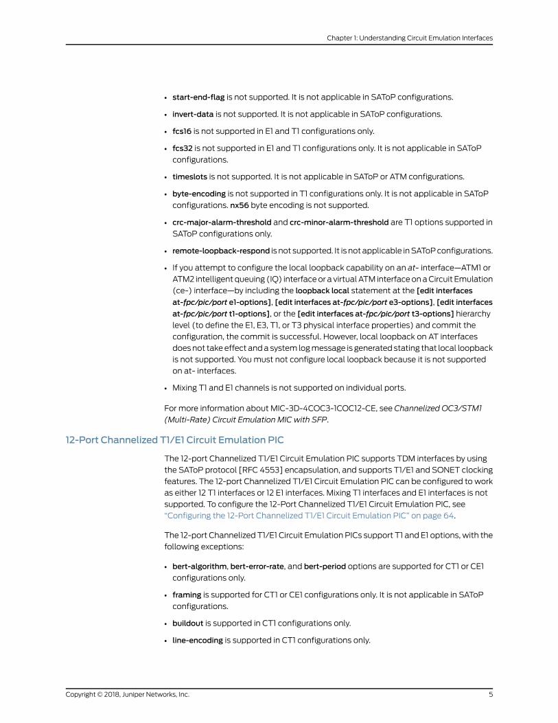
12-Port Channelized T1/E1 Circuit Emulation PIC
The 12-port Channelized T1/E1 Circuit Emulation PIC supports TDM interfaces by using
the SAToP protocol [RFC 4553] encapsulation, and supports T1/E1 and SONET clocking
features. The 12-port Channelized T1/E1 Circuit Emulation PIC can be configured to work
as either 12 T1 interfaces or 12 E1 interfaces. Mixing T1 interfaces and E1 interfaces is not
supported. To configure the 12-Port Channelized T1/E1 Circuit Emulation PIC, see
“Configuring the 12-Port Channelized T1/E1 Circuit Emulation PIC” on page 64.
The 12-port Channelized T1/E1 Circuit Emulation PICs support T1 and E1 options, with the
following exceptions:
• bert-algorithm, bert-error-rate, and bert-period options are supported for CT1 or CE1
configurations only.
• framing is supported for CT1 or CE1 configurations only. It is not applicable in SAToP
configurations.
• buildout is supported in CT1 configurations only.
• line-encoding is supported in CT1 configurations only.
5Copyright © 2018, Juniper Networks, Inc.
Chapter 1: Understanding Circuit Emulation Interfaces
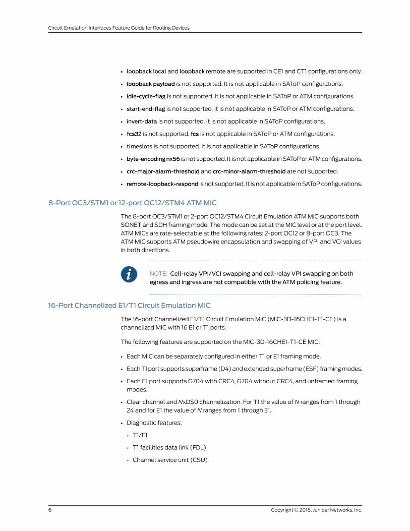
• loopback local and loopback remote are supported in CE1 and CT1 configurations only.
• loopback payload is not supported. It is not applicable in SAToP configurations.
• idle-cycle-flag is not supported. It is not applicable in SAToP or ATM configurations.
• start-end-flag is not supported. It is not applicable in SAToP or ATM configurations.
• invert-data is not supported. It is not applicable in SAToP configurations.
• fcs32 is not supported. fcs is not applicable in SAToP or ATM configurations.
• timeslots is not supported. It is not applicable in SAToP configurations.
• byte-encodingnx56 is not supported. It is notapplicable inSAToPorATMconfigurations.
• crc-major-alarm-threshold and crc-minor-alarm-threshold are not supported.
• remote-loopback-respond is not supported. It is notapplicable inSAToPconfigurations.
8-Port OC3/STM1 or 12-port OC12/STM4ATMMIC
The 8-port OC3/STM1 or 2-port OC12/STM4 Circuit Emulation ATMMIC supports both
SONETandSDH framingmode. Themode can be set at theMIC level or at the port level.
ATMMICs are rate-selectable at the following rates: 2-port OC12 or 8-port OC3. The
ATMMIC supports ATM pseudowire encapsulation and swapping of VPI and VCI values
in both directions.
NOTE: Cell-relay VPI/VCI swapping and cell-relay VPI swapping on bothegress and ingress are not compatible with the ATM policing feature.
16-Port Channelized E1/T1 Circuit EmulationMIC
The 16-port Channelized E1/T1 Circuit Emulation MIC (MIC-3D-16CHE1-T1-CE) is a
channelized MIC with 16 E1 or T1 ports.
The following features are supported on the MIC-3D-16CHE1-T1-CE MIC:
• Each MIC can be separately configured in either T1 or E1 framingmode.
• EachT1port supportssuperframe(D4)andextendedsuperframe(ESF) framingmodes.
• Each E1 port supports G704 with CRC4, G704 without CRC4, and unframed framing
modes.
• Clear channel and NxDS0 channelization. For T1 the value of N ranges from 1 through
24 and for E1 the value of N ranges from 1 through 31.
• Diagnostic features:
• T1/E1
• T1 facilities data link (FDL)
• Channel service unit (CSU)
Copyright © 2018, Juniper Networks, Inc.6
Circuit Emulation Interfaces Feature Guide for Routing Devices

• Bit error rate test (BERT)
• Juniper Integrity Test (JIT)
• T1/E1 alarm and performancemonitoring (a Layer 1 OAM function)
• External (loop) timing and internal (system) timing
• TDM circuit emulation services CESoPSN and SAToP
• CoS parity with IQE PICs. The CoS features supported on MPCs are supported on this
MIC.
• Encapsulations:
• ATM CCC cell relay
• ATM CCC VCmultiplex
• ATM VCmultiplex
• Multilink Point-to-Point Protocol (MLPPP)
• Multilink Frame Relay (MLFR) FRF.15
• Multilink Frame Relay (MLFR) FRF.16
• Point-to-Point Protocol (PPP)
• Cisco High-Level Data Link Control
• ATM class-of-service (CoS) features—traffic shaping, scheduling, and policing
• ATMOperation, Administration, and Maintenance
• Graceful Routing Engine switchover (GRES)
NOTE:• When GRES is enabled youmust execute the clear interface statistics
(interface-name | all)operationalmodecommandto reset thecumulative
values for local statistics. For more information, see Resetting LocalStatistics.
• Unified ISSU is not supported on the 16-port Channelized E1/T1 CircuitEmulation MIC (MIC-3D-16CHE1-T1-CE).
Formore informationaboutMIC-3D-16CHE1-T1-CE, seeChannelizedE1/T1CircuitEmulation
MIC.
Layer 2 Circuit Standards
Junos OS substantially supports the following Layer 2 circuit standards:
• RFC 4447, Pseudowire Setup and Maintenance Using the Label Distribution Protocol
(LDP) (except section 5.3)
• RFC 4448, Encapsulation Methods for Transport of Ethernet over MPLS Networks
7Copyright © 2018, Juniper Networks, Inc.
Chapter 1: Understanding Circuit Emulation Interfaces
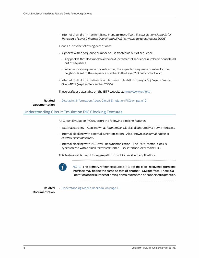
• Internet draft draft-martini-l2circuit-encap-mpls-11.txt, Encapsulation Methods for
Transport of Layer 2 Frames Over IP and MPLS Networks (expires August 2006)
Junos OS has the following exceptions:
• A packet with a sequence number of 0 is treated as out of sequence.
• Any packet that does not have the next incremental sequence number is considered
out of sequence.
• When out-of-sequence packets arrive, the expected sequence number for the
neighbor is set to the sequence number in the Layer 2 circuit control word.
• Internet draft draft-martini-l2circuit-trans-mpls-19.txt, Transport of Layer 2 Frames
Over MPLS (expires September 2006).
These drafts are available on the IETF website at http://www.ietf.org/.
RelatedDocumentation
Displaying Information About Circuit Emulation PICs on page 101•
Understanding Circuit Emulation PIC Clocking Features
All Circuit Emulation PICs support the following clocking features:
• External clocking—Also known as loop timing. Clock is distributed via TDM interfaces.
• Internal clocking with external synchronization—Also known as external timing or
external synchronization.
• Internal clocking with PIC-level line synchronization—The PIC’s internal clock is
synchronized with a clock recovered from a TDM interface local to the PIC.
This feature set is useful for aggregation in mobile backhaul applications.
NOTE: The primary reference source (PRS) of the clock recovered from oneinterfacemay not be the same as that of another TDM interface. There is alimitationon thenumberof timingdomains that canbesupported inpractice.
RelatedDocumentation
Understanding Mobile Backhaul on page 13•
Copyright © 2018, Juniper Networks, Inc.8
Circuit Emulation Interfaces Feature Guide for Routing Devices
Understanding ATMQoS or Shaping
M7i, M10i, M40e, M120, and M320 routers with 4-port Channelized OC3/STM1 Circuit
Emulation PICs and 12-port T1/E1 Circuit Emulation PICs and MX Series routers with
Channelized OC3/STM1 (Multi-Rate) Circuit Emulation MIC with SFP and 16-port
Channelized E1/T1 Circuit Emulation MIC support ATM pseudowire service with QoS
features for ingress and egress direction traffic shaping. Policing is performed by
monitoring the configured parameters on the incoming traffic and is also referred to as
ingress shaping. Egress shaping uses queuing and scheduling to shape the outgoing
traffic. Classification is providedper virtual circuit (VC). ToconfigureATMQoSor shaping,
see “Configuring ATMQoS or Shaping” on page 96.
The following QoS features are supported:
• CBR, rtVBR, nrtVBR, and UBR
• Policing on a per VC basis
• Independent PCR and SCR policing
• Counting policing actions
Circuit EmulationPICsprovidepseudowire service towards thecore.This sectiondescribes
the ATM service QoS features.
Circuit Emulation PICs support two types of ATM pseudowires:
• cell—atm-ccc-cell-relay encapsulation
• aal5—atm-ccc-vc-mux
NOTE: Only ATM pseudowires are supported; no other encapsulation typesare supported.
Since cells within a VC cannot be re-ordered, and since only the VC is mapped to a
pseudowire, classification is not meaningful in the context of a pseudowire. However,
different VCs can bemapped to different classes of traffic and can be classified in the
core network.
Such a service would connect two ATM networks with an IP/MPLS core.
Figure 1 onpage 10shows that the routersmarkedPEareequippedwithCircuit Emulation
PICs.
9Copyright © 2018, Juniper Networks, Inc.
Chapter 1: Understanding Circuit Emulation Interfaces
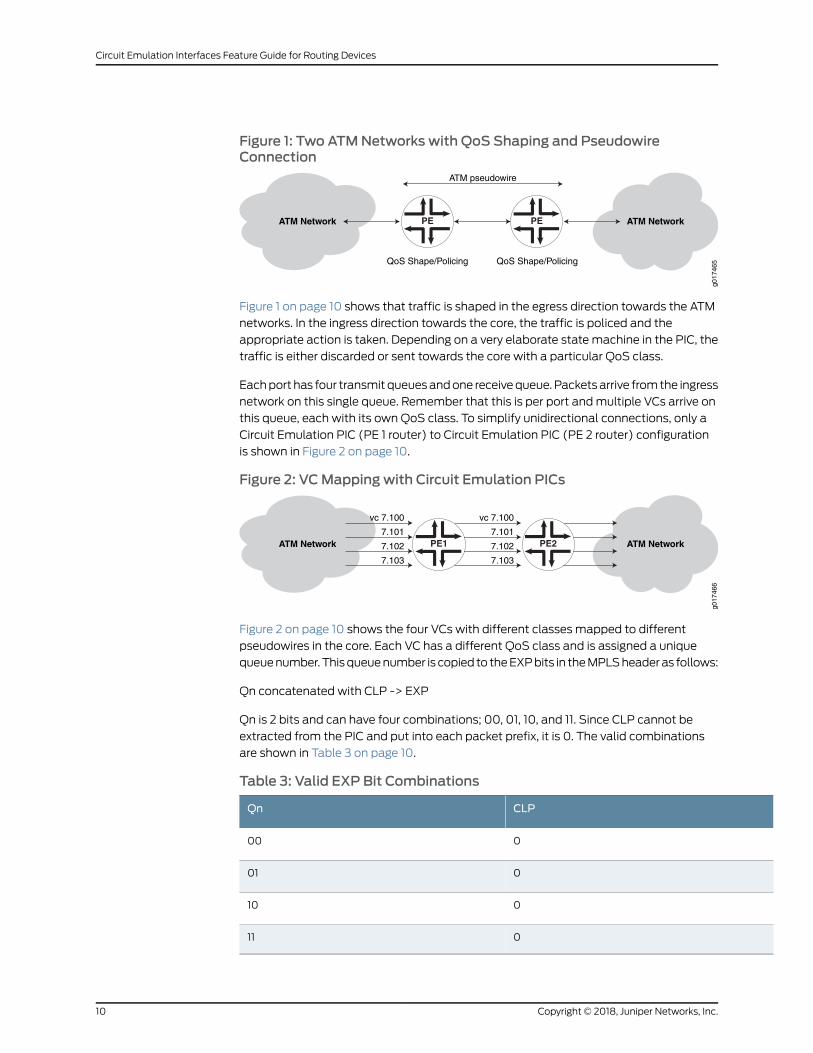
Figure 1: Two ATMNetworks with QoS Shaping and PseudowireConnection
ATM Network
g017
465
ATM Network PEPE
QoS Shape/Policing QoS Shape/Policing
ATM pseudowire
Figure 1 on page 10 shows that traffic is shaped in the egress direction towards the ATM
networks. In the ingress direction towards the core, the traffic is policed and the
appropriate action is taken. Depending on a very elaborate state machine in the PIC, the
traffic is either discarded or sent towards the core with a particular QoS class.
Eachport has four transmit queuesandone receivequeue.Packetsarrive fromthe ingress
network on this single queue. Remember that this is per port andmultiple VCs arrive on
this queue, each with its own QoS class. To simplify unidirectional connections, only a
Circuit Emulation PIC (PE 1 router) to Circuit Emulation PIC (PE 2 router) configuration
is shown in Figure 2 on page 10.
Figure 2: VCMapping with Circuit Emulation PICs
ATM Network
g017
466
ATM Network
vc 7.100
7.101
7.102
7.103
vc 7.100
7.101
7.102
7.103
PE2PE1
Figure 2 on page 10 shows the four VCs with different classes mapped to different
pseudowires in the core. Each VC has a different QoS class and is assigned a unique
queuenumber.Thisqueuenumber is copied to theEXPbits in theMPLSheaderas follows:
Qn concatenated with CLP -> EXP
Qn is 2 bits and can have four combinations; 00, 01, 10, and 11. Since CLP cannot be
extracted from the PIC and put into each packet prefix, it is 0. The valid combinations
are shown in Table 3 on page 10.
Table 3: Valid EXP Bit Combinations
CLPQn
000
001
010
011
Copyright © 2018, Juniper Networks, Inc.10
Circuit Emulation Interfaces Feature Guide for Routing Devices
For example, VC 7.100 has CBR, VC 7.101 has rt-VBR, 7.102 has nrt-VBR, 7.103 has UBR,
and each VC is assigned a queue number as follows:
• VC 7.100 -> 00
• VC 7.101 -> 01
• VC 7.102 -> 10
• VC 7.103 -> 11
NOTE: Lower queue numbers have higher priorities.
Each VCwill have the following EXP bits:
• VC 7.100 -> 000
• VC 7.101 -> 010
• VC 7.102 -> 100
• VC 7.103 -> 110
Apacket arriving onVC 7.100 at the ingress router has the queue number 00before being
forwarded to thePacketForwardingEngine.ThePacketForwardingEngine then translates
this to 000 EXP bits in the core. At the egress router, the Packet Forwarding Engine
retranslates this to queue 00 and stamps the packet with this queue number. The PIC
receiving this queue number sends the packet out on the transmit queue that ismapped
to queue 0, which could be the highest priority transmit queue on the egress side.
To briefly summarize, shaping and policing are possible. Classification is possible at the
VC level by mapping a specific VC to a particular class.
RelatedDocumentation
• ATM Support on Circuit Emulation PICs Overview on page 59
• Configuring ATMQoS or Shaping on page 96
• shaping
11Copyright © 2018, Juniper Networks, Inc.
Chapter 1: Understanding Circuit Emulation Interfaces

Copyright © 2018, Juniper Networks, Inc.12
Circuit Emulation Interfaces Feature Guide for Routing Devices
CHAPTER 2
Understanding How Circuit EmulationInterfaces Support Converged NetworksThat Accommodate Both IP And LegacyServices
• Understanding Mobile Backhaul on page 13
UnderstandingMobile Backhaul
In a network of core routers, edge routers, access networks, and other components, the
network paths that exist between the core network and edge subnetworks are known
as backhaul. This backhaul can be designed as a wired backhaul setup or a wireless
backhaul setup or as a combination of both on the basis of your requirement. In amobile
network, the network path between the cell tower and service provider is considered to
be backhaul and is called mobile backhaul.
The following sections explainmobile backhaul application solutionand IP/MPLS-based
mobile backhaul solution.
• Mobile Backhaul Application Overview on page 13
• IP/MPLS-based Mobile Backhaul on page 14
Mobile Backhaul Application Overview
This topic providesanapplicationexample (seeFigure 3onpage 14)basedon themobile
backhaul referencemodelwhere customeredge 1 (CE1) is abase stationcontroller (BSC),
provider edge 1 (PE1) is a cell site router, PE2 is anMSeries (aggregation) router, and CE2
is a BSC and Radio Network Controller (RNC). The Internet Engineering Task Force (RFC
3895) describes pseudowire as “a mechanism that emulates the essential attributes of
a telecommunications service (such as a T1 leased line or Frame Relay) over a PSN”
(Packet Switching Network).
13Copyright © 2018, Juniper Networks, Inc.
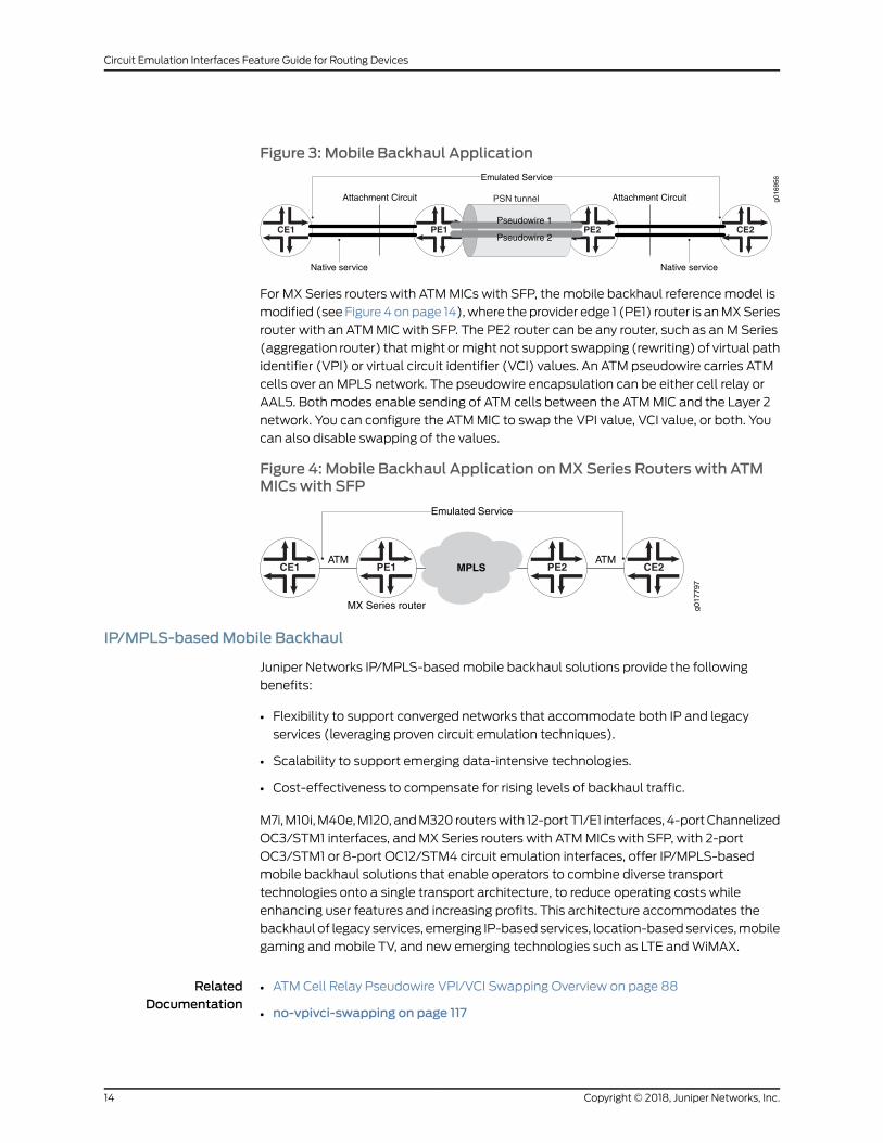
Figure 3: Mobile Backhaul Application
PE2PE1CE1 CE2
PSN tunnel
Pseudowire 1
Pseudowire 2
Attachment Circuit Attachment Circuit
Emulated Service
Native service Native service
g016
956
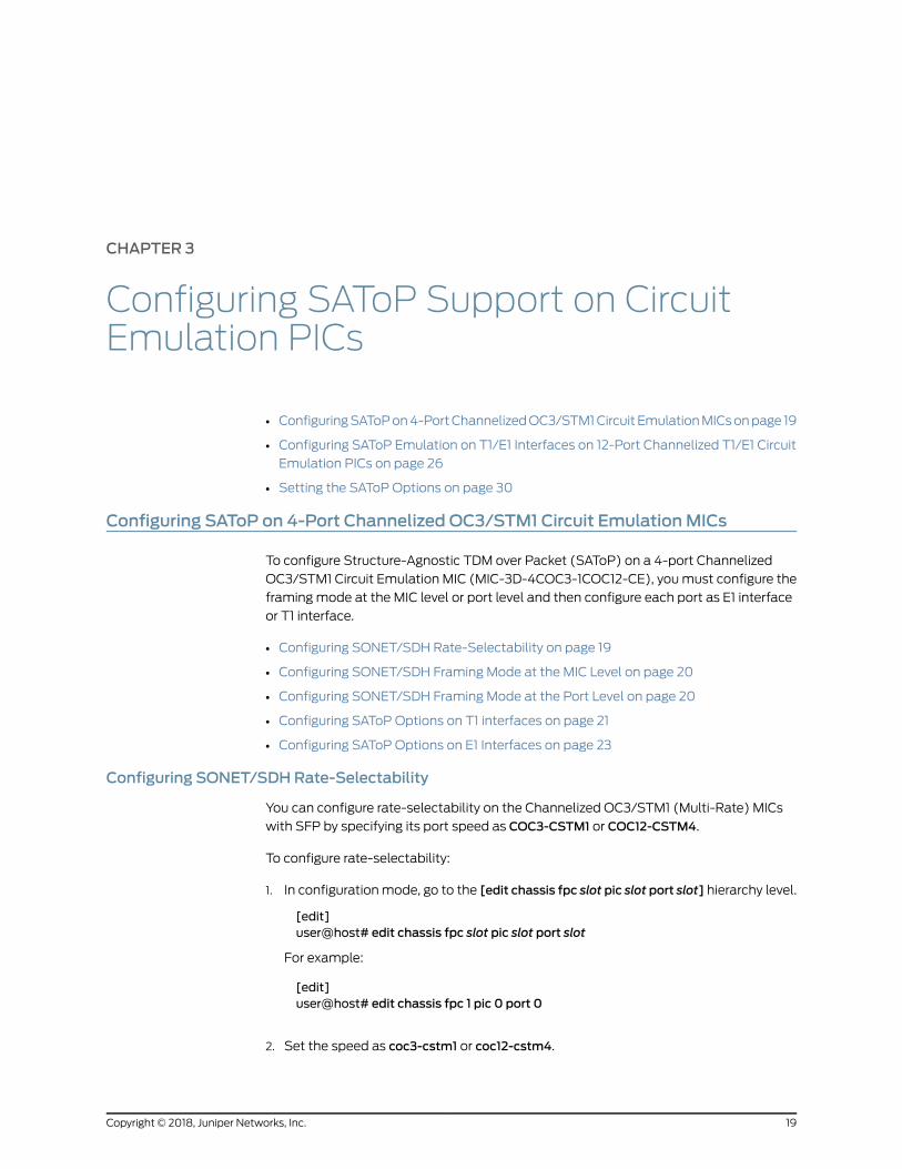
For MX Series routers with ATMMICs with SFP, the mobile backhaul referencemodel is
modified (see Figure 4 onpage 14),where the provider edge 1 (PE1) router is anMXSeries
router with an ATMMIC with SFP. The PE2 router can be any router, such as an M Series
(aggregation router) thatmight ormight not support swapping (rewriting) of virtual path
identifier (VPI) or virtual circuit identifier (VCI) values. An ATM pseudowire carries ATM
cells over an MPLS network. The pseudowire encapsulation can be either cell relay or
AAL5. Both modes enable sending of ATM cells between the ATMMIC and the Layer 2
network. You can configure the ATMMIC to swap the VPI value, VCI value, or both. You
can also disable swapping of the values.
Figure 4: Mobile Backhaul Application onMX Series Routers with ATMMICswith SFP
PE2PE1CE1 CE2
g017
797
MPLS
MX Series router
ATMATM
Emulated Service
IP/MPLS-basedMobile Backhaul
Juniper Networks IP/MPLS-basedmobile backhaul solutions provide the following
benefits:
• Flexibility to support converged networks that accommodate both IP and legacy
services (leveraging proven circuit emulation techniques).
• Scalability to support emerging data-intensive technologies.
• Cost-effectiveness to compensate for rising levels of backhaul traffic.
M7i,M10i,M40e,M120,andM320 routerswith 12-portT1/E1 interfaces, 4-portChannelized
OC3/STM1 interfaces, and MX Series routers with ATMMICs with SFP, with 2-port
OC3/STM1 or 8-port OC12/STM4 circuit emulation interfaces, offer IP/MPLS-based
mobile backhaul solutions that enable operators to combine diverse transport
technologies onto a single transport architecture, to reduce operating costs while
enhancing user features and increasing profits. This architecture accommodates the
backhaul of legacy services, emerging IP-based services, location-based services,mobile
gaming andmobile TV, and new emerging technologies such as LTE andWiMAX.
RelatedDocumentation
• ATM Cell Relay Pseudowire VPI/VCI Swapping Overview on page 88
• no-vpivci-swapping on page 117
Copyright © 2018, Juniper Networks, Inc.14
Circuit Emulation Interfaces Feature Guide for Routing Devices

• psn-vci on page 118
• psn-vpi on page 119
15Copyright © 2018, Juniper Networks, Inc.
Chapter 2: Understanding HowCircuit Emulation Interfaces Support Converged Networks That Accommodate Both IP And Legacy Services

Copyright © 2018, Juniper Networks, Inc.16
Circuit Emulation Interfaces Feature Guide for Routing Devices

PART 2
Configuring Circuit Emulation Interfaces
• Configuring SAToP Support on Circuit Emulation PICs on page 19
• Configuring SAToP Support on Circuit Emulation MICs on page 33
• Configuring CESoPSN Support on Circuit Emulation MIC on page 41
• Configuring ATM Support on Circuit Emulation PICs on page 59
17Copyright © 2018, Juniper Networks, Inc.

Copyright © 2018, Juniper Networks, Inc.18
Circuit Emulation Interfaces Feature Guide for Routing Devices
CHAPTER 3
Configuring SAToP Support on CircuitEmulation PICs
• ConfiguringSAToPon4-PortChannelizedOC3/STM1Circuit EmulationMICsonpage 19
• Configuring SAToP Emulation on T1/E1 Interfaces on 12-Port Channelized T1/E1 Circuit
Emulation PICs on page 26
• Setting the SAToP Options on page 30
Configuring SAToP on 4-Port Channelized OC3/STM1 Circuit EmulationMICs
To configure Structure-Agnostic TDM over Packet (SAToP) on a 4-port Channelized
OC3/STM1 Circuit Emulation MIC (MIC-3D-4COC3-1COC12-CE), youmust configure the
framingmode at the MIC level or port level and then configure each port as E1 interface
or T1 interface.
• Configuring SONET/SDH Rate-Selectability on page 19
• Configuring SONET/SDH Framing Mode at the MIC Level on page 20
• Configuring SONET/SDH Framing Mode at the Port Level on page 20
• Configuring SAToP Options on T1 interfaces on page 21
• Configuring SAToP Options on E1 Interfaces on page 23
Configuring SONET/SDHRate-Selectability
You can configure rate-selectability on the Channelized OC3/STM1 (Multi-Rate) MICs
with SFP by specifying its port speed as COC3-CSTM1 or COC12-CSTM4.
To configure rate-selectability:
1. In configurationmode, go to the [edit chassis fpc slot pic slot port slot] hierarchy level.
[edit]user@host# edit chassis fpc slot pic slot port slot
For example:
[edit]user@host# edit chassis fpc 1 pic 0 port 0
2. Set the speed as coc3-cstm1 or coc12-cstm4.
19Copyright © 2018, Juniper Networks, Inc.

[edit chassis fpc slot pic slot port slot]user@host# set speed (coc3-cstm1 | coc12-cstm4)
For example:
[edit chassis fpc 1 pic 0 port 0]user@host# set speed coc3-cstm1
NOTE: Whenthespeed is setascoc12-cstm4, insteadofconfiguringCOC3
ports down to T1 channels and CSTM1 ports down to E1 channels, youmust configure COC12 ports down to T1 channels and CSTM4 channelsdown to E1 channels.
Configuring SONET/SDH FramingMode at theMIC Level
To configure framingmode at the MIC level:
1. Go to the [edit chassis fpc fpc-slot pic pic-slot] hierarchy level.
[edit][edit chassis fpc fpc-slot pic pic-slot]
2. Configure the framingmode as SONET for COC3 or SDH for CSTM1.
[edit chassis fpc fpc-slot pic pic-slot]user@host# set framing (sonet | sdh)
After a MIC is brought online, interfaces are created for the MIC’s available ports on the
basis of the MIC type and the configured framingmode of each port:
• When the framing sonet statement (for a COC3Circuit EmulationMIC) is enabled, four
COC3 interfaces are created.
• When the framing sdh statement (for a CSTM1 Circuit Emulation MIC) is enabled, four
CSTM1 interfaces are created.
• Note that when you do not specify framingmode at the MIC level, then the default
framingmode is SONET for all the four ports.
NOTE: If you set the framing option incorrectly for the MIC type, the commit
operation fails.
Bit error rate test (BERT) patterns with all ones received by T1/E1 interfaceson Circuit Emulation MICs configured for SAToP do not result in an alarmindication signal (AIS) defect. As a result, the T1/E1 interfaces remain up.
Configuring SONET/SDH FramingMode at the Port Level
Each port’s framingmode can be configured individually, as either COC3 (SONET) or
STM1 (SDH).Ports not configured for framing retain theMIC framingconfiguration,which
Copyright © 2018, Juniper Networks, Inc.20
Circuit Emulation Interfaces Feature Guide for Routing Devices

is SONET by default if you have not specified framing at theMIC level. To set the framing
mode for individual ports, include the framing statement at the [edit chassis fpc fpc-slot
pic pic-slot port port-number] hierarchy level:
To configure the framingmode as SONET for COC3 or SDH for CSTM1 at port level:
1. Go to the [edit chassis fpc fpc-slot pic pic-slot port port-number] hierarchy level.
[edit][edit chassis fpc fpc-slot pic pic-slot port port-number]
2. Configure the framingmode as SONET for COC3 or SDH for CSTM1.
[edit chassis fpc fpc-slot pic pic-slot port port-number]user@host# set framing (sonet | sdh)
NOTE: Configuring the framingmodeat theport leveloverwrites thepreviousMIC-level framingmode configuration for the specified port. Subsequently,configuring the MIC-level framingmode overwrites the port-level framingconfiguration. For example, if youwant three STM1 ports and oneCOC3port,then it is practical to first configure the MIC for SDH framing and thenconfigure one port for SONET framing.
Configuring SAToPOptions on T1 interfaces
To configure the SAToP on an T1 interface, youmust perform the following tasks:
1. Configuring COC3 Ports Down to T1 Channels on page 21
2. Configuring SAToP Options on a T1 interface on page 22
Configuring COC3 Ports Down to T1 Channels
On any port (numbered 0 through 3) configured for SONET framing, you can configure
three COC1 channels (numbered 1 through 3). On each COC1 channel, you can configure
28 T1 channels (numbered 1 through 28).
To configure COC3 channelization down to COC1 and then down to T1 channels:
1. In configuration mode, go to the [edit interfaces coc3-fpc-slot/pic-slot/port]
[edit]user@host# edit interfaces coc3-fpc-slot/pic-slot/port
For example:
[edit]user@host# edit interfaces coc3-1/0/0
2. Configure the sublevel interface partition index, range of SONET/SDH slices, and
sublevel interface type.
[edit interfaces coc3-fpc-slot/pic-slot/port]
21Copyright © 2018, Juniper Networks, Inc.
Chapter 3: Configuring SAToP Support on Circuit Emulation PICs
user@host# set partition partition-number oc-slice oc-slice interface-type coc1
For example:
[edit interfaces coc3-1/0/0]user@host# set partition 1 oc-slice 1 interface-type coc1
3. Enter up command to go to [edit interfaces] hierarchy level.
[edit interfaces coc3-fpc-slot/pic-slot/port]user@host# up
4. Configure the channelized OC1 interface, sublevel interface partition index, and the
interface type.
[edit interfaces]user@host#setcoc1-fpc-slot/pic-slot/port:channel-numberpartitionpartition-numberinterface-type t1
For example:
[edit interfaces]user@host# set coc1-1/0/0:1 partition 1 interface-type t1
5. Enter up to go to [edit interfaces] hierarchy level.
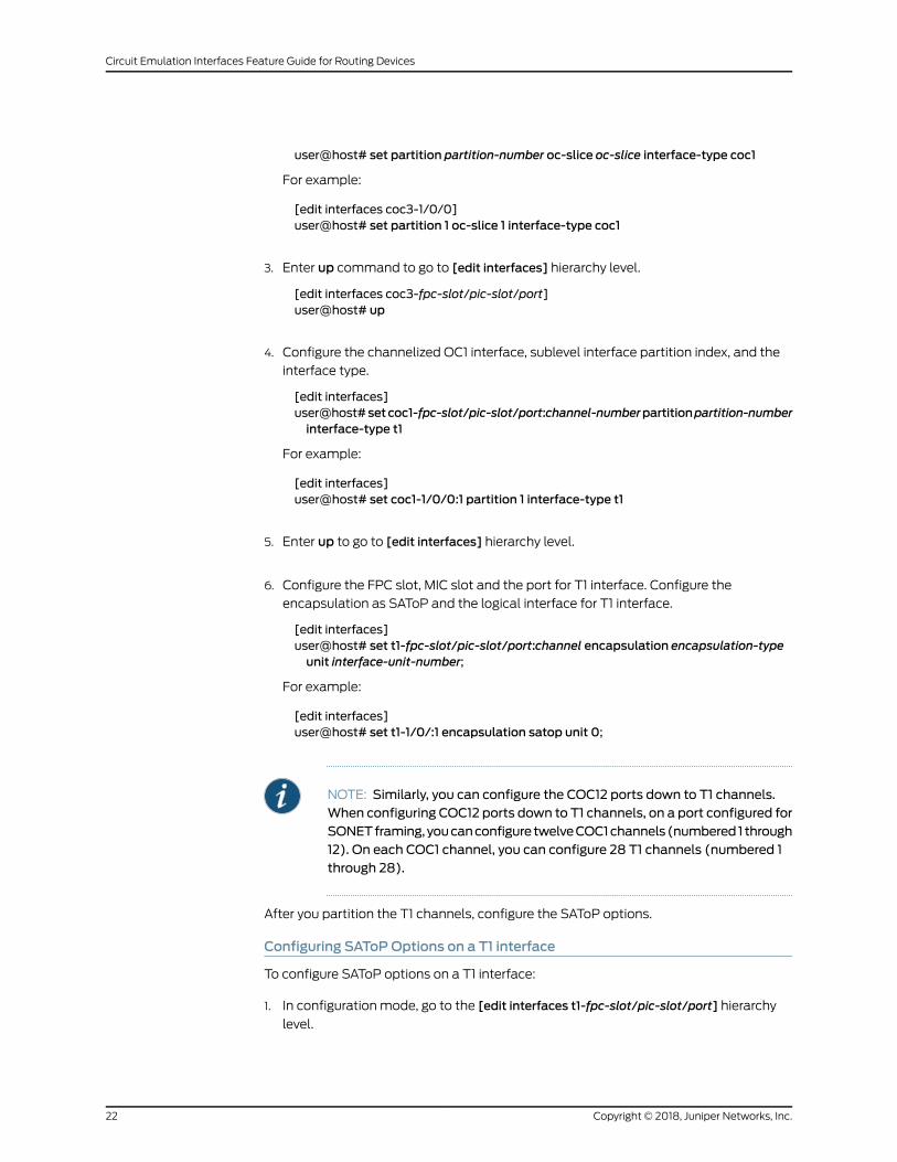
6. Configure the FPC slot, MIC slot and the port for T1 interface. Configure the
encapsulation as SAToP and the logical interface for T1 interface.
[edit interfaces]user@host# set t1-fpc-slot/pic-slot/port:channel encapsulation encapsulation-typeunit interface-unit-number;
For example:
[edit interfaces]user@host# set t1-1/0/:1 encapsulation satop unit 0;
NOTE: Similarly, you can configure the COC12 ports down to T1 channels.When configuring COC12 ports down to T1 channels, on a port configured forSONETframing,youcanconfigure twelveCOC1channels(numbered1 through12). On each COC1 channel, you can configure 28 T1 channels (numbered 1through 28).
After you partition the T1 channels, configure the SAToP options.
Configuring SAToPOptions on a T1 interface
To configure SAToP options on a T1 interface:
1. In configuration mode, go to the [edit interfaces t1-fpc-slot/pic-slot/port] hierarchy
level.
Copyright © 2018, Juniper Networks, Inc.22
Circuit Emulation Interfaces Feature Guide for Routing Devices
[edit]user@host# edit interfaces t1-fpc-slot/pic-slot/port
2. Use the edit command to go to the satop-options hierarchy level.
[edit interfaces t1-fpc-slot/pic-slot/port]user@host# edit satop-options
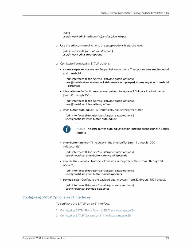
3. Configure the following SAToP options:
• excessive-packet-loss-rate—Setpacket lossoptions. Theoptionsare sample-period
and threshold.
[edit interfaces t1-fpc-slot/pic-slot/port satop-options]user@host#setexcessive-packet-loss-ratesample-periodsample-period thresholdpercentile
• idle-pattern—An 8-bit hexadecimal pattern to replace TDM data in a lost packet
(from 0 through 255).
[edit interfaces t1-fpc-slot/pic-slot/port satop-options]user@host# set idle-pattern pattern
• jitter-buffer-auto-adjust—Automatically adjust the jitter buffer.
[edit interfaces t1-fpc-slot/pic-slot/port satop-options]user@host# set jitter-buffer-auto-adjust
NOTE: The jitter-buffer-auto-adjustoption isnotapplicableonMXSeries
routers.
• jitter-buffer-latency—Time delay in the jitter buffer (from 1 through 1000
milliseconds).
[edit interfaces t1-fpc-slot/pic-slot/port satop-options]user@host# set jitter-buffer-latencymilliseconds
• jitter-buffer-packets—Number of packets in the jitter buffer (from 1 through 64
packets).
[edit interfaces t1-fpc-slot/pic-slot/port satop-options]user@host# set jitter-buffer-packets packets
• payload-size—Configure the payload size, in bytes (from 32 through 1024 bytes).
[edit interfaces t1-fpc-slot/pic-slot/port satop-options]user@host# set payload-size bytes
Configuring SAToPOptions on E1 Interfaces
To configure the SAToP on an E1 interface.
1. Configuring CSTM1 Ports Down to E1 Channels on page 24
2. Configuring SAToP Options on E1 Interfaces on page 25
23Copyright © 2018, Juniper Networks, Inc.
Chapter 3: Configuring SAToP Support on Circuit Emulation PICs

Configuring CSTM1 Ports Down to E1 Channels
On any port (numbered 0 through 3) configured for SDH framing, you can configure one
CAU4 channel. On each CAU4 channel, you can configure 63 E1 channels (numbered 1
through 63).
To configure CSTM1 channelization down to CAU4 and then down to E1 channels.
1. In configuration mode, go to the [edit interfaces cstm1-fpc-slot/pic-slot/port]
[edit][edit interfaces cstm1-fpc-slot/pic-slot/port]
For example:
[edit][edit interfaces cstm1-1/0/1]
2. Configure the channelize interface as clear channel and the set the interface-type as
cau4
[edit interfaces cstm1-fpc-slot/pic-slot/port]user@host# set no-partition interface-type cau4;
3. Enter up to go to [edit interfaces] hierarchy level.
4. Configure theFPCslot,MIC slot and theport forCAU4 interface.Configure the sublevel
interface partition index and the interface type as E1.
[edit interfaces]user@host# set cau4-fpc-slot/pic-slot/portpartitionpartition-number interface-typee1
For example:
[edit interfaces]user@host# set cau4-1/0/1 partition 1 interface-type e1
5. Enter up to go to [edit interfaces] hierarchy level.
6. Configure the FPC slot, MIC slot and the port for E1 interface. Configure the
encapsulation as SAToP and the logical interface for E1 interface.
[edit interfaces]user@host# set e1-fpc-slot/pic-slot/port:channel encapsulation encapsulation-typeunit interface-unit-number;
For example:
[edit interfaces]user@host# set e1-1/0/:1 encapsulation satop unit 0;
Copyright © 2018, Juniper Networks, Inc.24
Circuit Emulation Interfaces Feature Guide for Routing Devices
NOTE: Similarly, youcanconfigure theCSTM4channelsdowntoE1channels.
After you configure the E1 channels, configure the SAToP options.
Configuring SAToPOptions on E1 Interfaces
To configure SAToP options on E1 interfaces:
1. In configuration mode, go to the [edit interfaces e1-fpc-slot/pic-slot/port] hierarchy
level.
[edit]user@host# edit interfaces e1-fpc-slot/pic-slot/port
2. Use the edit command to go to the satop-options hierarchy level.
[edit interfaces e1-fpc-slot/pic-slot/port]user@host# edit satop-options
3. Configure the following SAToP options:
• excessive-packet-loss-rate—Setpacket lossoptions. Theoptionsare sample-period
and threshold.
[edit interfaces e1-fpc-slot/pic-slot/port satop-options]user@host#setexcessive-packet-loss-ratesample-periodsample-period thresholdpercentile
• idle-pattern—An 8-bit hexadecimal pattern to replace TDM data in a lost packet
(from 0 through 255).
[edit interfaces e1-fpc-slot/pic-slot/port satop-options]user@host# set idle-pattern pattern
• jitter-buffer-auto-adjust—Automatically adjust the jitter buffer.
[edit interfaces e1-fpc-slot/pic-slot/port satop-options]user@host# set jitter-buffer-auto-adjust
NOTE: The jitter-buffer-auto-adjustoption isnotapplicableonMXSeries
routers.
• jitter-buffer-latency—Time delay in the jitter buffer (from 1 through 1000
milliseconds).
[edit interfaces e1-fpc-slot/pic-slot/port satop-options]user@host# set jitter-buffer-latencymilliseconds
• jitter-buffer-packets—Number of packets in the jitter buffer (from 1 through 64
packets).
[edit interfaces e1-fpc-slot/pic-slot/port satop-options]user@host# set jitter-buffer-packets packets
25Copyright © 2018, Juniper Networks, Inc.
Chapter 3: Configuring SAToP Support on Circuit Emulation PICs
• payload-size—Configure the payload size, in bytes (from 32 through 1024 bytes).
[edit interfaces e1-fpc-slot/pic-slot/port satop-options]user@host# set payload-size bytes
RelatedDocumentation
Understanding Circuit Emulation Services and the Supported PIC Types on page 3•
Configuring SAToPEmulation on T1/E1 Interfaces on 12-Port Channelized T1/E1 CircuitEmulation PICs
The following sections describes configuring SAToP on the 12-port Channelized T1/E1
Circuit Emulation PICs:
• Setting the Emulation Mode on page 26
• Configuring SAToP Emulation on T1/E1 Interfaces on page 26
Setting the EmulationMode
To set the framing emulation mode, include the framing statement at the [edit chassis
fpc fpc-slot pic pic-slot] hierarchy level:
[edit chassis fpc fpc-slot pic pic-slot]user@host# set framing (t1 | e1);
After a PIC is brought online, interfaces are created for thePIC’s available ports according
to the PIC type and the framing option used:
• If you include the framing t1 statement (for aT1Circuit EmulationPIC), 12CT1 interfaces
are created.
• If you include the framinge1 statement (for anE1Circuit EmulationPIC), 12CE1 interfaces
are created.
NOTE: If you set the framing option incorrectly for the PIC type, the commit
operation fails.
CircuitEmulationPICswithSONETandSDHports requirepriorchannelizationdown to T1 or E1 before you can configure them.Only T1/E1 channels supportSAToP encapsulation or SAToP options.
Bit error rate test (BERT) patterns with all ones received by T1/E1 interfaceson Circuit Emulation PICs configured for SAToP do not result in an alarmindication signal (AIS) defect. As a result, the T1/E1 interfaces remain up.
Configuring SAToP Emulation on T1/E1 Interfaces
• Setting the Encapsulation Mode on page 27
• Configuring Loopback for a T1 Interface or an E1 Interface on page 27
Copyright © 2018, Juniper Networks, Inc.26
Circuit Emulation Interfaces Feature Guide for Routing Devices

• Setting the SAToP Options on page 27
• Configuring the Pseudowire Interface on page 29
Setting the EncapsulationMode
E1 channels on Circuit Emulation PICs can be configured with SAToP encapsulation at
the provider edge (PE) router, as follows:
NOTE: ThebelowmentionedprocedurecanbeusedtoconfigureT1channelson circuit emulation PICs with SAToP encapsulation at the PE router.
1. In the configuration mode, go to [edit interfaces e1-fpc-slot/pic-slot/port] hierarchy
level.
[edit]user@host# [edit interfaces e1 fpc-slot/pic-slot/port]
For example:
[edit][edit interfaces e1-1/0/0]
2. Configure SAToP encapsulation and the logical interface for E1 interface
[edit interfaces e1-1/0/0]user@host# set encapsulation encapsulation-typeunit interface-unit-number;
For example:
[edit interfaces e1-1/0/0]user@host# set encapsulation satop unit 0;
You do not need to configure any cross-connect circuit family because it is automatically
created for the above encapsulation.
Configuring Loopback for a T1 Interface or an E1 Interface
To configure loopback capability between the local T1 interface and the remote channel
service unit (CSU), see Configuring T1 Loopback Capability. To configure loopback
capability between the local E1 interface and the remote channel service unit (CSU), see
Configuring E1 Loopback Capability.
NOTE: By default, no loopback is configured.
Setting the SAToPOptions
To configure SAToP options on T1/E1 interfaces:
1. In configuration mode, go to the [edit interfaces e1-fpc-slot/pic-slot/port] hierarchy
level.
[edit]
27Copyright © 2018, Juniper Networks, Inc.
Chapter 3: Configuring SAToP Support on Circuit Emulation PICs

user@host# edit interfaces e1-fpc-slot/pic-slot/port
For example:
[edit]user@host# edit interfaces e1-1/0/0
2. Use the edit command to go to the satop-options hierarchy level.
[edit]user@host# edit satop-options
3. In this hierarchy level, using the set command you can configure the following SAToP
options:
• excessive-packet-loss-rate—Set packet loss options. The options are groups,
sample-period, and threshold.
• groups—Specify groups.
• sample-period—Time required to calculate excessive packet loss rate (from 1000
through 65,535milliseconds).
• threshold—Percentile designating the threshold of excessive packet loss rate
(1–100 percent).
• idle-pattern—An 8-bit hexadecimal pattern to replace TDM data in a lost packet
(from 0 through 255).
• jitter-buffer-auto-adjust—Automatically adjust the jitter buffer.
NOTE: The jitter-buffer-auto-adjustoption isnotapplicableonMXSeries
routers.
• jitter-buffer-latency—Time delay in the jitter buffer (from 1 through 1000
milliseconds).
• jitter-buffer-packets—Number of packets in the jitter buffer (from 1 through 64
packets).
• payload-size—Configure the payload size, in bytes (from 32 through 1024 bytes).
NOTE: In this section, we are configuring only one SAToP option. You canfollow the samemethod to configure all the other SAToP options.
[edit interfaces e1-1/0/0 satop-options]user@host# set excessive-packet-loss-rate sample-period sample-period
For example:
[edit interfaces e1-1/0/0 satop-options]user@host# set excessive-packet-loss-rate sample-period 4000
Copyright © 2018, Juniper Networks, Inc.28
Circuit Emulation Interfaces Feature Guide for Routing Devices

To verify this configuration, use the show command at the [edit interfaces e1-1/0/0]hierarchy level:
[edit interfaces e1-1/0/0]user@host# showsatop-options {excessive-packet-loss-rate {sample-period 4000;
}}
See Also satop-options on page 120•
Configuring the Pseudowire Interface
To configure the TDM pseudowire at the provider edge (PE) router, use the existing
Layer 2 circuit infrastructure, as shown in the following procedure:
1. In the configuration mode, go to [edit protocols l2circuit] hierarchy level.
[edit]user@host# edit protocol l2circuit
2. Configure the IP address of the neighboring router or switch, interface forming the
layer 2 circuit and the identifier for the layer 2 circuit.
[edit protocol l2circuit]user@host# set neighbor ip-address interfaceinterface-name-fpc-slot/pic-slot/port.interface-unit-number virtual-circuit-idvirtual-circuit-id;
NOTE: To configure T1 interface as the layer 2 circuit, replace e1 with t1 inthe below statement.
For example:
[edit protocol l2circuit]user@host# set neighbor 10.255.0.6 interface e1-1/0/0.0 virtual-circuit-id 1
3. To verify the configuration use the show command at the [edit protocols l2circuit]
hierarchy level.
[edit protocols l2circuit]user@host# showneighbor 10.255.0.6 {interface e1-1/0/0.0 {virtual-circuit-id 1;
}}
After the customer edge (CE)-bound interfaces (for bothPE routers) are configuredwith
proper encapsulation, payload size, and other parameters, the two PE routers try to
29Copyright © 2018, Juniper Networks, Inc.
Chapter 3: Configuring SAToP Support on Circuit Emulation PICs
establish a pseudowire with Pseudowire Emulation Edge-to-Edge (PWE3) signaling
extensions. The following pseudowire interface configurations are disabled or ignored
for TDM pseudowires:
• ignore-encapsulation
• mtu
The supported pseudowire types are:
• 0x0011 Structure-Agnostic E1 over Packet
• 0x0012 Structure-Agnostic T1 (DS1) over Packet
When the local interfaceparametersmatch the receivedparameters, and thepseudowire
type and control word bit are equal, the pseudowire is established.
For detailed information about configuring TDM pseudowire, see the Junos OS VPNs
Library for Routing Devices.
For detailed information about PICs, see the PIC Guide for your router.
NOTE: When T1 is used for SAToP, the T1 facility data-link (FDL) loop is notsupportedontheCT1 interfacedevice.The isbecauseSAToPdoesnotanalyzeT1 framing bits.
RelatedDocumentation
Understanding Mobile Backhaul on page 13•
• Understanding Circuit Emulation Services and the Supported PIC Types on page 3
• ConfiguringSAToPon4-PortChannelizedOC3/STM1Circuit EmulationMICsonpage 19
Setting the SAToPOptions
To configure SAToP options on T1/E1 interfaces:
1. In configuration mode, go to the [edit interfaces e1-fpc-slot/pic-slot/port] hierarchy
level.
[edit]user@host# edit interfaces e1-fpc-slot/pic-slot/port
For example:
[edit]user@host# edit interfaces e1-1/0/0
2. Use the edit command to go to the satop-options hierarchy level.
[edit]user@host# edit satop-options
Copyright © 2018, Juniper Networks, Inc.30
Circuit Emulation Interfaces Feature Guide for Routing Devices

3. In this hierarchy level, using the set command you can configure the following SAToP
options:
• excessive-packet-loss-rate—Set packet loss options. The options are groups,
sample-period, and threshold.
• groups—Specify groups.
• sample-period—Time required to calculate excessive packet loss rate (from 1000
through 65,535milliseconds).
• threshold—Percentile designating the threshold of excessive packet loss rate
(1–100 percent).
• idle-pattern—An 8-bit hexadecimal pattern to replace TDM data in a lost packet
(from 0 through 255).
• jitter-buffer-auto-adjust—Automatically adjust the jitter buffer.
NOTE: The jitter-buffer-auto-adjustoption isnotapplicableonMXSeries
routers.
• jitter-buffer-latency—Time delay in the jitter buffer (from 1 through 1000
milliseconds).
• jitter-buffer-packets—Number of packets in the jitter buffer (from 1 through 64
packets).
• payload-size—Configure the payload size, in bytes (from 32 through 1024 bytes).
NOTE: In this section, we are configuring only one SAToP option. You canfollow the samemethod to configure all the other SAToP options.
[edit interfaces e1-1/0/0 satop-options]user@host# set excessive-packet-loss-rate sample-period sample-period
For example:
[edit interfaces e1-1/0/0 satop-options]user@host# set excessive-packet-loss-rate sample-period 4000
To verify this configuration, use the show command at the [edit interfaces e1-1/0/0]hierarchy level:
[edit interfaces e1-1/0/0]user@host# showsatop-options {excessive-packet-loss-rate {sample-period 4000;
}}
31Copyright © 2018, Juniper Networks, Inc.
Chapter 3: Configuring SAToP Support on Circuit Emulation PICs

RelatedDocumentation
• satop-options on page 120
Copyright © 2018, Juniper Networks, Inc.32
Circuit Emulation Interfaces Feature Guide for Routing Devices

CHAPTER 4
Configuring SAToP Support on CircuitEmulation MICs
• Configuring SAToP on 16-Port Channelized E1/T1 Circuit Emulation MIC on page 33
• Configuring SAToP Encapsulation on T1/E1 Interfaces on page 36
Configuring SAToP on 16-Port Channelized E1/T1 Circuit EmulationMIC
The following sections describes configuring SAToP on the 16-Port Channelized E1/T1
Circuit Emulation MIC (MIC-3D-16CHE1-T1-CE).
• Configuring T1/E1 Framing Mode at the MIC Level on page 33
• Configuring CT1 Ports Down to T1 Channels on page 34
• Configuring CT1 Ports Down to DS Channels on page 35
Configuring T1/E1 FramingMode at theMIC Level
To configure the framing emulation mode at the MIC level.
1. Go to the [edit chassis fpc fpc-slot pic pic-slot] hierarchy level.
[edit][edit chassis fpc fpc-slot pic pic-slot]
2. Configure the framing emulation mode as E1 or T1.
[edit chassis fpc fpc-slot pic pic-slot]user@host# set framing (t1 | e1)
After a MIC is brought online, interfaces are created for the MIC’s available ports on the
basis of the MIC type and the framing option used:
• If you include the framing t1 statement, 16 channelized T1 (CT1) interfaces are created.
• If you include the framing e1 statement, 16 channelized E1 (CE1) interfaces are created.
33Copyright © 2018, Juniper Networks, Inc.
NOTE: If you set the framing option incorrectly for the MIC type, the commit
operation fails.
By default, t1 framingmode is selected.
CircuitEmulationPICswithSONETandSDHports requirepriorchannelizationdown to T1 or E1 before you can configure them.Only T1/E1 channels supportSAToP encapsulation or SAToP options.
Bit error rate test (BERT) patternswith all binary 1s (ones) receivedbyCT1/CE1 interfaces
onCircuit EmulationMICs configured for SAToPdonot result in an alarm indication signal
(AIS) defect. As a result, the CT1/CE1 interfaces remain up.
Configuring CT1 Ports Down to T1 Channels
To configure a CT1 port down to a T1 channel, use the following procedure:
NOTE: To configure a CE1 port down to the E1 channel, replace ct1 with ce1and t1 with e1 in the procedure.
1. In configuration mode, go to the [edit interfaces ct1-mpc-slot/mic-slot/port-number]
hierarchy level.
[edit]user@host# edit interfaces ct1-mpc-slot/mic-slot/port-number
For example:
[edit]user@host# edit interfaces ct1-1/0/0
2. On the CT1 interface, set the no-partition option and then set the interface type as T1.
[edit interfaces ct1-mpc-slot/mic-slot/port-number]user@host# set no-partition interface-type t1
In the following example, the ct1-1/0/1 interface is configured to be of type T1 and tohave no partitions.
[edit interfaces ct1-1/0/1]user@host# set no-partition interface-type t1
Copyright © 2018, Juniper Networks, Inc.34
Circuit Emulation Interfaces Feature Guide for Routing Devices
Configuring CT1 Ports Down to DS Channels
To configure a channelized T1 (CT1) port down to a DS channel, include the partition
statement at the [edit interfaces ct1-mpc-slot/mic-slot/port-number] hierarchy level:
NOTE: To configure a CE1 port down to a DS channel, replace ct1 with ce1 inthe following procedure.
1. In configuration mode, go to the [edit interfaces ct1-mpc-slot/mic-slot/port-number]
hierarchy level.
[edit]user@host# edit interfaces ct1-mpc-slot/mic-slot/port-number
For example:
[edit]user@host# edit interfaces ct1-1/0/0
2. Configure the partition, the time slot, and the interface type.
[edit interfaces ct1-mpc-slot/mic-slot/port-number]user@host# set partition partition-number timeslots timeslots interface-type ds
In the following example, the ct1-1/0/0 interface is configured as a DS interface withone partition and three time slots:
[edit interfaces ct1-1/0/0]user@host# set partition 1 timeslots 1-4,9,22-24 interface-type ds
To verify the configuration of the ct1-1/0/0 interface, use the show command at the [editinterfaces ct1-1/0/0] hierarchy level.
[edit interfaces ct1-1/0/0]user@host# showpartition 1 timeslots 1-4,9,22-24 interface-type ds;
An NxDS0 interface can be configured from channelized T1 interface. Here N represents
the time slots on the CT1 interface. The value of N is:
• 1 through 24 when a DS0 interface is configured from a CT1 interface.
• 1 through 31 when a DS0 interface is configured from a CE1 interface.
After you partition the DS interface, configure the SAToP options on it. See “Setting the
SAToP Options” on page 27.
RelatedDocumentation
Understanding Circuit Emulation Services and the Supported PIC Types on page 3•
• Setting the SAToP Options on page 27
35Copyright © 2018, Juniper Networks, Inc.
Chapter 4: Configuring SAToP Support on Circuit Emulation MICs
Configuring SAToP Encapsulation on T1/E1 Interfaces
This configurationapplies to themobilebackhaulapplicationshown inFigure3onpage 14.
This topic includes the following tasks:
• Setting the Encapsulation Mode on page 36
• T1/E1 Loopback Support on page 36
• T1 FDL Support on page 37
• Setting the SAToP Options on page 37
• Configuring the Pseudowire Interface on page 38
Setting the EncapsulationMode
E1 channels on Circuit Emulation MICs can be configured with SAToP encapsulation at
the provider edge (PE) router, as follows:
NOTE: The following procedure can be used to configure T1 channels onCircuit Emulation MICs with SAToP encapsulation at the PE router.
1. In configuration mode, go to the [edit interfaces e1-fpc-slot/pic-slot/port] hierarchy
level.
[edit]user@host# edit interfaces e1-fpc-slot/pic-slot/port
For example:
[edit]user@host# edit interfaces e1-1/0/0
2. Configure the SAToP encapsulation and the logical interface for E1 interface.
[edit interfaces e1-1/0/0]user@host# set encapsulation satop unit interface-unit-number
For example:
[edit interfaces e1-1/0/0]user@host# set encapsulation satop unit 0
You do not need to configure any cross-connect circuit family because it is automatically
created for the SAToP encapsulation.
T1/E1 Loopback Support
Use the CLI to configure remote and local loopback as T1 (CT1) or E1 (CE1). By default,
no loopback is configured. See Configuring T1 Loopback Capability and Configuring E1
Loopback Capability.
Copyright © 2018, Juniper Networks, Inc.36
Circuit Emulation Interfaces Feature Guide for Routing Devices

T1 FDL Support
If T1 is used for SAToP, the T1 facility data-link (FDL) loop is not supported on the CT1
interface device because SAToP does not analyze T1 framing bits.
Setting the SAToPOptions
To configure SAToP options on T1/E1 interfaces:
1. In configuration mode, go to the [edit interfaces e1-fpc-slot/pic-slot/port] hierarchy
level.
[edit]user@host# edit interfaces e1-fpc-slot/pic-slot/port
For example:
[edit]user@host# edit interfaces e1-1/0/0
2. Use the edit command to go to the satop-options hierarchy level.
[edit]user@host# edit satop-options
3. In this hierarchy level, using the set command you can configure the following SAToP
options:
• excessive-packet-loss-rate—Set packet loss options. The options are groups,
sample-period, and threshold.
• groups—Specify groups.
• sample-period—Time required to calculate excessive packet loss rate (from 1000
through 65,535milliseconds).
• threshold—Percentile designating the threshold of excessive packet loss rate
(1–100 percent).
• idle-pattern—An 8-bit hexadecimal pattern to replace TDM data in a lost packet
(from 0 through 255).
• jitter-buffer-auto-adjust—Automatically adjust the jitter buffer.
NOTE: The jitter-buffer-auto-adjustoption isnotapplicableonMXSeries
routers.
• jitter-buffer-latency—Time delay in the jitter buffer (from 1 through 1000
milliseconds).
• jitter-buffer-packets—Number of packets in the jitter buffer (from 1 through 64
packets).
• payload-size—Configure the payload size, in bytes (from 32 through 1024 bytes).
37Copyright © 2018, Juniper Networks, Inc.
Chapter 4: Configuring SAToP Support on Circuit Emulation MICs
NOTE: In this section, we are configuring only one SAToP option. You canfollow the samemethod to configure all the other SAToP options.
[edit interfaces e1-1/0/0 satop-options]user@host# set excessive-packet-loss-rate sample-period sample-period
For example:
[edit interfaces e1-1/0/0 satop-options]user@host# set excessive-packet-loss-rate sample-period 4000
To verify this configuration, use the show command at the [edit interfaces e1-1/0/0]hierarchy level:
[edit interfaces e1-1/0/0]user@host# showsatop-options {excessive-packet-loss-rate {sample-period 4000;
}}
See Also satop-options on page 120•
Configuring the Pseudowire Interface
To configure the TDM pseudowire at the provider edge (PE) router, use the existing
Layer 2 circuit infrastructure, as shown in the following procedure:
1. In configuration mode, go to the [edit protocols l2circuit] hierarchy level.
[edit]user@host# edit protocol l2circuit
2. Configure the IP address of the neighboring router or switch, the interface forming the
Layer 2 circuit, and the identifier for the Layer 2 circuit.
[edit protocol l2circuit]user@host# set neighbor ip-address interfaceinterface-name-fpc-slot/pic-slot/port.interface-unit-number virtual-circuit-idvirtual-circuit-id
NOTE: To configure the T1 interface as the Layer 2 circuit, replace e1witht1 in the configuration statement.
For example:
[edit protocol l2circuit]user@host# set neighbor 10.255.0.6 interface e1-1/0/0.0 virtual-circuit-id 1
Copyright © 2018, Juniper Networks, Inc.38
Circuit Emulation Interfaces Feature Guide for Routing Devices
3. To verify this configuration, use the show command at the [edit protocols l2circuit]
hierarchy level.
[edit protocols l2circuit]user@host# showneighbor 10.255.0.6 {interface e1-1/0/0.0 {virtual-circuit-id 1;
}}
After the customer edge (CE)-bound interfaces (for bothPE routers) are configuredwith
proper encapsulation, payload size, and other parameters, the two PE routers try to
establish a pseudowire with Pseudowire Emulation Edge-to-Edge (PWE3) signaling
extensions. The following pseudowire interface configurations are disabled or ignored
for TDM pseudowires:
• ignore-encapsulation
• mtu
The supported pseudowire types are:
• 0x0011 Structure-Agnostic E1 over Packet
• 0x0012 Structure-Agnostic T1 (DS1) over Packet
When the local interfaceparametersmatch the receivedparameters, and thepseudowire
type and control word bit are equal, the pseudowire is established.
For detailed information about configuring TDM pseudowire, see the Junos OS VPNs
Library for Routing Devices.
For detailed information about MICs, see the PIC Guide for your router.
RelatedDocumentation
• Understanding Mobile Backhaul on page 13
39Copyright © 2018, Juniper Networks, Inc.
Chapter 4: Configuring SAToP Support on Circuit Emulation MICs

Copyright © 2018, Juniper Networks, Inc.40
Circuit Emulation Interfaces Feature Guide for Routing Devices
CHAPTER 5
Configuring CESoPSN Support on CircuitEmulation MIC
• Configuring CESoPSN on Channelized E1/T1 Circuit Emulation MIC on page 41
• Configuring CESoPSN on Channelized OC3/STM1 (Multi-Rate) Circuit Emulation MIC
with SFP on page 45
• Configuring CESoPSN Encapsulation on DS Interfaces on page 54
Configuring CESoPSN on Channelized E1/T1 Circuit EmulationMIC
To configure Circuit Emulation Service over Packet-Switched Network (CESoPSN)
protocol on a 16-port Channelized E1/T1 Circuit EmulationMIC (MIC-3D-16CHE1-T1-CE),
youmust configure the framingmode, configure CT1 interface down to DS channels, and
configure the CESoPSN encapsulation on DS interfaces.
• Configuring T1/E1 Framing Mode at the MIC Level on page 41
• Configuring CT1 Interface Down to DS Channels on page 42
• Setting the CESoPSNOptions on page 43
• Configuring CESoPSN on DS Interfaces on page 44
Configuring T1/E1 FramingMode at theMIC Level
To set the framingmode at the MIC (MIC-3D-16CHE1-T1-CE) level, for all four ports on
the MIC, include the framing statement at the [edit chassis fpc slot pic slot] hierarchy
level.
[edit chassis fpc slot pic slot]user@host# set framing (t1 | e1);
After a MIC is brought online, interfaces are created for the MIC’s available ports on the
basis of the MIC type and the framing option used.
• If you include the framing t1 statement, 16 CT1 interfaces are created.
• If you include the framing e1 statement, 16 CE1 interfaces are created.
41Copyright © 2018, Juniper Networks, Inc.

NOTE: If you set the framing option incorrectly for the MIC type, the commit
operation fails.
Bit error rate test (BERT)patternswithallbinary 1s (ones) receivedbyCT1/CE1interfaces on Circuit Emulation MICs configured for CESoPSN do not resultin an alarm indication signal (AIS) defect. As a result, the CT1/CE1 interfacesremain up.
Configuring CT1 Interface Down to DS Channels
To configure a channelized T1 (CT1) interface down to DS channels, include the partition
statement at the [edit interfaces ct1-mpc-slot/mic-slot/port-number] hierarchy level:
NOTE: To configure a CE1 interface down to DS channels, replace ct1with
ce1 in the following procedure.
1. In configuration mode, go to the [edit interfaces ct1-mpc-slot/mic-slot/port-number]
hierarchy level.
[edit]user@host# edit interfaces ct1-mpc-slot/mic-slot/port-number
For example:
[edit]user@host# edit interfaces ct1-1/0/0
2. Configure the sublevel interfacepartition indexand the timeslots, andset the interface
type as ds.
[edit interfaces ct1-mpc-slot/mic-slot/port-number]user@host# set partition partition-number timeslots timeslots interface-type ds
For example:
[edit interfaces ct1-1/0/0]user@host# set partition 1 timeslots 1-4 interface-type ds
NOTE: You can assignmultiple time slots on a CT1 interface. In the set
command, separate the time slots by commas and do not include spacesbetween them. For example:
[edit interfaces ct1-1/0/0]user@host# set partition 1 timeslots 1-4,9,22-24 interface-type ds
To verify this configuration, use the show command at the [edit interfaces ct1-1/0/0]hierarchy level.
[edit interfaces ct1-1/0/0]
Copyright © 2018, Juniper Networks, Inc.42
Circuit Emulation Interfaces Feature Guide for Routing Devices
user@host# showpartition 1 timeslots 1-4 interface-type ds;
AnNxDS0 interfacecanbeconfigured fromaCT1 interface.HereN represents thenumber
of time slots on the CT1 interface. The value of N is:
• 1 through 24 when a DS0 interface is configured from a CT1 interface.
• 1 through 31 when a DS0 interface is configured from a CE1 interface.
After you partition the DS interface, configure CESoPSN options on it.
Setting the CESoPSNOptions
To configure CESoPSN options:
1. In configuration mode, go to the [edit interfaces ds-fpc-slot/pic-slot/port:channel]
hierarchy level.
[edit]user@host# edit interfaces ds-fpc-slot/pic-slot/port:channel
For example:
[edit]user@host# edit interfaces ds-1/0/0:1:1:1
2. Use the edit command to go to the [edit cesopsn-options] hierarchy level.
[edit interfaces ds-fpc-slot/pic-slot/port:channel]user@host# edit cesopsn-options
3. Configure the following CESoPSN options:
NOTE: Whenyoustitchpseudowiresbyusing interworking(iw) interfaces,the device stitching the pseudowire cannot interpret the characteristicsof the circuit because the circuits originate and terminate in other nodes.To negotiate between the stitching point and circuit endpoints, you needto configure the following options.
• excessive-packet-loss-rate—Setpacket lossoptions. Theoptionsare sample-period
and threshold.
[edit interfaces ds-fpc-slot/pic-slot/port:channel cesopsn-options]user@host# set excessive-packet-loss-rate sample-period sample-period
• idle-pattern—An 8-bit hexadecimal pattern to replace TDM data in a lost packet
(from 0 through 255).
• jitter-buffer-latency—Time delay in the jitter buffer (from 1 through 1000
milliseconds).
• jitter-buffer-packets—Number of packets in the jitter buffer (from 1 through 64
packets).
43Copyright © 2018, Juniper Networks, Inc.
Chapter 5: Configuring CESoPSN Support on Circuit Emulation MIC
• packetization-latency—Time required to create packets (from 1000 through 8000
microseconds).
• payload-size—Payload size for virtual circuits that terminate on Layer 2 interworking
(iw) logical interfaces (from 32 through 1024 bytes).
To verify the configuration using the values shown in the examples, use the showcommand at the [edit interfaces ds-1/0/0:1:1:1] hierarchy level:
[edit interfaces ds-1/0/0:1:1:1]user@host# showcesopsn-options {excessive-packet-loss-rate {sample-period 4000;
}}
See Also Setting the Encapsulation Mode on page 54•
• Configuring the Pseudowire Interface on page 57
Configuring CESoPSN on DS Interfaces
To configure CESoPSN encapsulation on a DS interface, include the encapsulation
statement at the [edit interfaces ds-mpc-slot/mic-slot/port-number:channel] hierarchy
level.
1. In configuration mode, go to the [edit interfaces
ds-mpc-slot/mic-slot/port-number:channel] hierarchy level.
[edit]user@host# edit interfaces ds-mpc-slot/mic-slot/ port-number:channel
For example:
[edit]user@host# edit interfaces ds-1/0/0:1
2. Configure CESoPSN as the encapsulation type.
[edit interfaces ds-mpc-slot/mic-slot/port-number:partition ]user@host# set encapsulation cesopsn
For example:
[edit interfaces ds-1/0/0:1 ]user@host# set encapsulation cesopsn
3. Configure the logical interface for the DS interface.
[edit interfaces ds-mpc-slot/mic-slot/port-number:partition ]uset@host# set unit interface-unit-number
For example:
[edit interfaces ds-1/0/0:1 ]
Copyright © 2018, Juniper Networks, Inc.44
Circuit Emulation Interfaces Feature Guide for Routing Devices
user@host# set unit 0
To verify this configuration, use the show command at the [edit interfaces ds-1/0/0:1]hierarchy level.
[edit interfaces ds-1/0/0:1]user@host# showencapsulation cesopsn;unit 0;
RelatedDocumentation
Understanding Circuit Emulation Services and the Supported PIC Types on page 3•
Configuring CESoPSN on Channelized OC3/STM1 (Multi-Rate) Circuit EmulationMICwith SFP
To configure CESoPSN options on a Channelized OC3/STM1 (Multi-Rate) Circuit
Emulation MIC with SFP, youmust configure the speed and framingmode at MIC level
and configure the encapsulation as CESoPSN on DS interfaces.
• Configuring SONET/SDH Rate-Selectability on page 45
• Configuring SONET/SDH Framing Mode at the MIC Level on page 46
• Configuring CESoPSN Encapsulation on DS Interfaces on CT1 Channels on page 46
• Configuring CESoPSN Encapsulation on DS Interfaces on CE1 Channels on page 50
Configuring SONET/SDHRate-Selectability
You can configure rate-selectability on the Channelized OC3/STM1 (Multi-Rate) MICs
with SFP(MIC-3D-4COC3-1COC12-CE) by specifying the port speed. The Channelized
OC3/STM1 (Multi-Rate) Circuit Emulation MIC with SFP is rate-selectable and its port
speed can be specified as COC3-CSTM1 or COC12-CSTM4.
To configure port speed to select a speed option of coc3-cstm1 or coc12-cstm4:
1. In configurationmode, go to the [edit chassis fpc slot pic slot port slot] hierarchy level.
[edit]user@host# edit chassis fpc slot pic slot port slot
For example:
[edit]user@host# edit chassis fpc 1 pic 0 port 0
2. Set the speed as coc3-cstm1 or coc12-cstm4.
[edit chassis fpc slot pic slot port slot]user@host# set speed (coc3-cstm1 | coc12-cstm4)
For example:
[edit chassis fpc 1 pic 0 port 0]user@host# set speed coc3-cstm1
45Copyright © 2018, Juniper Networks, Inc.
Chapter 5: Configuring CESoPSN Support on Circuit Emulation MIC
NOTE: Whenthespeed is setascoc12-cstm4, insteadofconfiguringCOC3
ports down to T1 channels and CSTM1 ports down to E1 channels, youmust configure COC12 ports down to T1 channels and CSTM4 channelsdown to E1 channels.
Configuring SONET/SDH FramingMode at theMIC Level
To set the framingmode at theMIC (MIC-3D-4COC3-1COC12-CE) level, for all four ports
on the MIC, include the framing statement at the [edit chassis fpc slot pic slot] hierarchy
level.
[edit chassis fpc slot pic slot]user@host#set framing(sonet |sdh)#SONETforCOC3/COC12orSDHforCSTM1/CSTM4
After a MIC is brought online, interfaces are created for the MIC’s available ports on the
basis of the MIC type and the framing option used.
• If you include the framing sonet statement, four COC3 interfaces are createdwhen the
speed is configured as coc3-cstm1.
• If you include the framing sdh statement, four CSTM1 interfaces are created when the
speed is configured as coc3-cstm1.
• If you include the framing sonet statement, one COC12 interface is created when the
speed is configured as coc12-cstm4.
• If you include the framing sdh statement, one CSTM4 interface is created when the
speed is configured as coc12-cstm4.
• If you do not specify framing at the MIC level, then the default framing is SONET for
all the ports.
NOTE: If you set the framing option incorrectly for the MIC type, the commit
operation fails.
Bit error rate test (BERT)patternswithallbinary 1s (ones) receivedbyCT1/CE1interfaces on Circuit Emulation MICs configured for CESoPSN do not resultin an alarm indication signal (AIS) defect. As a result, the CT1/CE1 interfacesremain up.
Configuring CESoPSN Encapsulation on DS Interfaces on CT1 Channels
This topic includes the following tasks:
1. Configuring COC3 Ports Down to CT1 Channels on page 47
2. Configuring CT1 Channels Down to DS Interfaces on page 48
3. Configuring CESoPSN on DS Interfaces on page 49
Copyright © 2018, Juniper Networks, Inc.46
Circuit Emulation Interfaces Feature Guide for Routing Devices

Configuring COC3 Ports Down to CT1 Channels
When configuring COC3 ports down to CT1 channels, on any MIC configured for SONET
framing (numbered 0 through 3), you can configure three COC1 channels (numbered 1
through 3). On each COC1 channel, you can configure a maximum of 28 CT1 channels
and aminimum of 1 CT1 channel based on the time slots.
When configuring COC12 ports down to CT1 channels on a MIC configured for SONET
framing, you can configure 12 COC1 channels (numbered 1 through 12). On each COC1
channel, you can configure 24 CT1 channels (numbered 1 through 28).
To configureCOC3channelizationdown toCOC1 and thendown toCT1 channels, include
thepartitionstatementat the [edit interfaces(coc1 |coc3)-mpc-slot/mic-slot/port-number]
hierarchy level:
NOTE: To configure COC12 ports down to CT1 channels, replace coc3with
coc12 in the following procedure.
1. In configurationmode, go to the [edit interfaces coc3-mpc-slot/mic-slot/port-number]
hierarchy level.
[edit]user@host# edit interfaces coc3-mpc-slot/mic-slot/port-number
For example:
[edit]user@host# edit interfaces coc3-1/0/0
2. Configure the sublevel interface partition index and the range of SONET/SDH slices,
and set the sublevel interface type as coc1.
[edit interfaces coc3-mpc-slot/mic-slot/port-number]user@host# set partition partition-number oc-slice oc-slice interface-type coc1
For example:
[edit interfaces coc3-1/0/0]user@host# set partition 1 oc-slice 1 interface-type coc1
3. Enter the up command to go to the [edit interfaces] hierarchy level.
[edit interfaces coc3-mpc-slot/mic-slot/port-number]user@host# up
For example:
[edit interfaces coc3-1/0/0]user@host# up
4. Configure the channelized OC1 interface and the sublevel interface partition index,
and set the interface type as ct1.
47Copyright © 2018, Juniper Networks, Inc.
Chapter 5: Configuring CESoPSN Support on Circuit Emulation MIC

[edit interfaces]user@host# set coc1-1/0/0:1 partition partition-number interface-type ct1
For example:
[edit interfaces]user@host# set coc1-1/0/0:1 partition 1 interface-type ct1
To verify the configuration, use the show command at the [edit interfaces] hierarchylevel.
[edit interfaces]user@host# showcoc3-1/0/0 {partition 1 oc-slice 1 interface-type coc1;
}coc1-1/0/0:1 {partition 1 interface-type ct1;
}
Configuring CT1 Channels Down to DS Interfaces
To configure CT1 channels down to a DS interface, include the partition statement at the
[edit interfaces ct1-mpc-slot/mic-slot/port-number:channel:channel] hierarchy level:
1. In configuration mode, go to the [edit interfaces
ct1-mpc-slot/mic-slot/port-number:channel:channel] hierarchy level.
[edit]user@host# edit interfaces ct1-mpc-slot/mic-slot/port-number:channel:channel
For example:
[edit]user@host# edit interfaces ct1-1/0/0:1:1
2. Configure the partition, the time slots, and the interface type.
[edit interfaces ct1-mpc-slot/mic-slot/port-number:channel:channel]user@host# set partition partition-number timeslots timeslots interface-type ds
For example:
[edit interfaces ct1-1/0/0:1:1]user@host# set partition 1 timeslots 1-4 interface-type ds
NOTE: You can assignmultiple time slots on a CT1 interface. In the set
command, separate the time slots by commas and do not include spacesbetween them. For example:
[edit interfaces ct1-1/0/0:1:1]user@host# set partition 1 timeslots 1-4,9,22-24 interface-type ds
Copyright © 2018, Juniper Networks, Inc.48
Circuit Emulation Interfaces Feature Guide for Routing Devices

To verify this configuration, use the show command at the [edit interfaces ct1-1/0/0:1:1]hierarchy level.
[edit interfaces ct1-1/0/0:1:1]user@host# showpartition 1 timeslots 1-4 interface-type ds;
An NxDS0 interface can be configured from channelized T1 interface (ct1). Here N
represents the time slots on the CT1 interface.
The value of N is 1 through 24 when a DS0 interface is configured from a CT1 interface.
After you partition the DS interface, configure the CESoPSN options on it. See “Setting
the CESoPSNOptions” on page 43.
Configuring CESoPSN on DS Interfaces
To configure CESoPSN encapsulation on a DS interface, include the encapsulation
statement at the [edit interfaces
ds-mpc-slot/mic-slot/port-number:channel:channel:channel] hierarchy level.
1. In configuration mode, go to the [edit interfaces
ds-mpc-slot/mic-slot/port-number:channel:channel:channel] hierarchy level.
[edit]user@host#edit interfacesds-mpc-slot/mic-slot/port-number:channel:channel:channel
For example:
[edit]user@host# edit interfaces ds-1/0/0:1:1:1
2. Configure CESoPSN as the encapsulation type and the logical interface for the DS
interface.
[edit interfaces ds-mpc-slot/mic-slot/port-number:channel:channel:channel]user@host# set encapsulation cesopsn unit interface-unit-number
For example:
[edit interfaces ds-1/0/0:1:1:1 ]user@host# set encapsulation cesopsn unit 0
To verify this configuration, use the show command at the [edit interfaces ds-1/0/0:1:1:1]hierarchy level.
[edit interfaces ds-1/0/0:1:1:1]user@host# showencapsulation cesopsn;unit 0;
See Also Understanding Mobile Backhaul on page 13•
• Configuring CESoPSN Encapsulation on DS Interfaces on page 54
49Copyright © 2018, Juniper Networks, Inc.
Chapter 5: Configuring CESoPSN Support on Circuit Emulation MIC
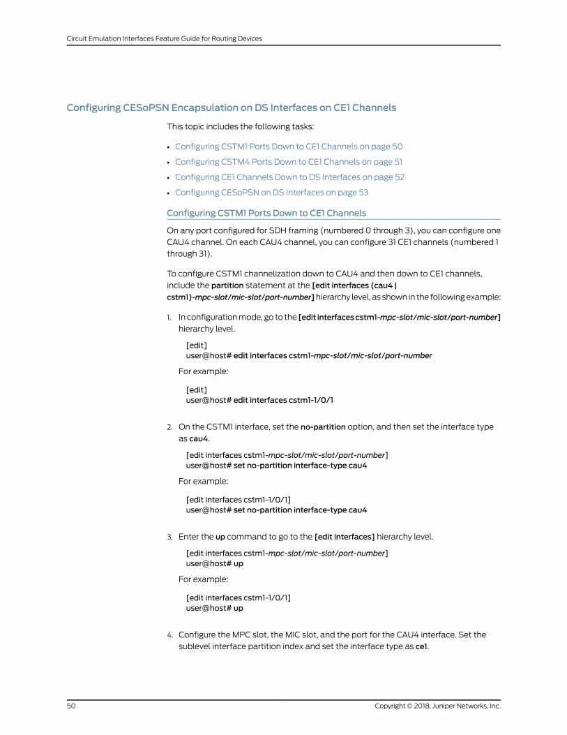
Configuring CESoPSN Encapsulation on DS Interfaces on CE1 Channels
This topic includes the following tasks:
• Configuring CSTM1 Ports Down to CE1 Channels on page 50
• Configuring CSTM4 Ports Down to CE1 Channels on page 51
• Configuring CE1 Channels Down to DS Interfaces on page 52
• Configuring CESoPSN on DS Interfaces on page 53
Configuring CSTM1 Ports Down to CE1 Channels
On any port configured for SDH framing (numbered 0 through 3), you can configure one
CAU4 channel. On each CAU4 channel, you can configure 31 CE1 channels (numbered 1
through 31).
To configure CSTM1 channelization down to CAU4 and then down to CE1 channels,
include the partition statement at the [edit interfaces (cau4 |
cstm1)-mpc-slot/mic-slot/port-number]hierarchy level, as shown in the followingexample:
1. In configurationmode, go to the [edit interfacescstm1-mpc-slot/mic-slot/port-number]
hierarchy level.
[edit]user@host# edit interfaces cstm1-mpc-slot/mic-slot/port-number
For example:
[edit]user@host# edit interfaces cstm1-1/0/1
2. On the CSTM1 interface, set the no-partition option, and then set the interface type
as cau4.
[edit interfaces cstm1-mpc-slot/mic-slot/port-number]user@host# set no-partition interface-type cau4
For example:
[edit interfaces cstm1-1/0/1]user@host# set no-partition interface-type cau4
3. Enter the up command to go to the [edit interfaces] hierarchy level.
[edit interfaces cstm1-mpc-slot/mic-slot/port-number]user@host# up
For example:
[edit interfaces cstm1-1/0/1]user@host# up
4. Configure the MPC slot, the MIC slot, and the port for the CAU4 interface. Set the
sublevel interface partition index and set the interface type as ce1.
Copyright © 2018, Juniper Networks, Inc.50
Circuit Emulation Interfaces Feature Guide for Routing Devices

[edit interfaces]user@host# set cau4-mpc-slot/mic-slot/port-number partition partition-numberinterface-type ce1
For example:
[edit interfaces]user@host# set cau4-1/0/1 partition 1 interface-type ce1
To verify this configuration, use the show command at the [edit interfaces] hierarchylevel.
[edit interfaces]user@host# showcstm1-1/0/1 {no-partition interface-type cau4;
}cau4-1/0/1 {partition 1 interface-type ce1;
}
Configuring CSTM4 Ports Down to CE1 Channels
NOTE: When the port speed is configured as coc12-cstm4 at the [edit chassis
fpc slot pic slot port slot] hierarchy level, youmust configure CSTM4 ports
down to CE1 channels.
Onaport configured forSDH framing, youcanconfigureoneCAU4channel.On theCAU4
channel, you can configure 31 CE1 channels (numbered 1 through 31).
To configure CSTM4 channelization down to CAU4 and then down to CE1 channels,
include the partition statement at the [edit interfaces
(cau4|cstm4)-mpc-slot/mic-slot/port-number] hierarchy level.
1. In configurationmode, go to the [edit interfacescstm4-mpc-slot/mic-slot/port-number]
hierarchy level.
[edit]user@host# edit interfaces cstm4-mpc-slot/mic-slot/port-number
For example:
[edit]user@host# edit interfaces cstm4-1/0/0
2. Configure the sublevel interface partition index and the range of SONET/SDH slices,
and set the sublevel interface type as cau4.
[edit interfaces cstm4-1/0/0]user@host# set partition partition-number oc-slice oc-slice interface-type cau4
For oc-slice, select from the following ranges: 1–3, 4–6, 7–9, and 10–12.
For partition, select a value from 1 through 4.
51Copyright © 2018, Juniper Networks, Inc.
Chapter 5: Configuring CESoPSN Support on Circuit Emulation MIC
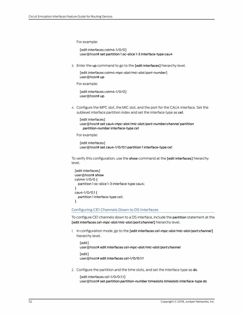
For example:
[edit interfaces cstm4-1/0/0]user@host# set partition 1 oc-slice 1-3 interface-type cau4
3. Enter the up command to go to the [edit interfaces] hierarchy level.
[edit interfaces cstm4-mpc-slot/mic-slot/port-number]user@host# up
For example:
[edit interfaces cstm4-1/0/0]user@host# up
4. Configure the MPC slot, the MIC slot, and the port for the CAU4 interface. Set the
sublevel interface partition index and set the interface type as ce1.
[edit interfaces]user@host# set cau4-mpc-slot/mic-slot/port-number:channel partitionpartition-number interface-type ce1
For example:
[edit interfaces]user@host# set cau4-1/0/0:1 partition 1 interface-type ce1
To verify this configuration, use the show command at the [edit interfaces] hierarchylevel.
[edit interfaces]user@host# showcstm4-1/0/0 {partition 1 oc-slice 1-3 interface-type cau4;
}cau4-1/0/0:1 {partition 1 interface-type ce1;
}
Configuring CE1 Channels Down to DS Interfaces
To configure CE1 channels down to a DS interface, include the partition statement at the
[edit interfaces ce1-mpc-slot/mic-slot/port:channel] hierarchy level.
1. In configuration mode, go to the [edit interfaces ce1-mpc-slot/mic-slot/port:channel]
hierarchy level.
[edit]user@host# edit interfaces ce1-mpc-slot/mic-slot/port:channel
[edit]user@host# edit interfaces ce1-1/0/0:1:1
2. Configure the partition and the time slots, and set the interface type as ds.
[edit interfaces ce1-1/0/0:1:1]user@host# set partition partition-number timeslots timeslots interface-type ds
Copyright © 2018, Juniper Networks, Inc.52
Circuit Emulation Interfaces Feature Guide for Routing Devices

For example:
[edit interfaces ce1-1/0/0:1:1]user@host# set partition 1 timeslots 1-4 interface-type ds
NOTE: You can assignmultiple time slots on a CE1 interface. In the set
command, separate the time slots by commas and do not include spacesbetween them. For example:
[edit interfaces ce1-1/0/0:1:1]user@host# set partition 1 timeslots 1-4,9,22-31 interface-type ds
To verify this configuration, use the show command at the [edit interfaces ce1-1/0/0:1:1hierarchy level.
[edit interfaces ce1-1/0/0:1:1 ]user@host# showpartition 1 timeslots 1-4 interface-type ds;
An NxDS0 interface can be configured from a channelized E1 interface (CE1). Here N
represents the number of time slots on the CE1 interface.
The value of N is 1 through 31 when a DS0 interface is configured from a CE1 interface.
After you partition the DS interface, configure the CESoPSN options.
See Also Understanding Mobile Backhaul on page 13•
• Configuring CESoPSN Encapsulation on DS Interfaces on page 54
Configuring CESoPSN on DS Interfaces
To configure CESoPSN encapsulation on a DS interface, include the encapsulation
statement at the [edit interfaces
ds-mpc-slot/mic-slot/port-number:channel:channel:channel] hierarchy level.
1. In configuration mode, go to the [edit interfaces
ds-mpc-slot/mic-slot/port-number:channel:channel:channel] hierarchy level.
[edit]user@host#edit interfacesds-mpc-slot/mic-slot/port-number:channel:channel:channel
For example:
[edit]user@host# edit interfaces ds-1/0/0:1:1:1
2. Configure CESoPSN as the encapsulation type and then set the logical interface for
the ds interface.
[edit interfaces ds-1/0/0:1:1:1 ]user@host# set encapsulation cesopsn unit interface-unit-number
53Copyright © 2018, Juniper Networks, Inc.
Chapter 5: Configuring CESoPSN Support on Circuit Emulation MIC

For example:
[edit interfaces ds-1/0/0:1:1:1 ]user@host# set encapsulation cesopsn unit 0
To verify this configuration, use the show command at the [edit interfaces ds-1/0/0:1:1:1]hierarchy level.
[edit interfaces ds-1/0/0:1:1:1]user@host# showencapsulation cesopsn;unit 0;
RelatedDocumentation
Understanding Mobile Backhaul on page 13•
• Configuring CESoPSN Encapsulation on DS Interfaces on page 54
RelatedDocumentation
Understanding Mobile Backhaul on page 13•
• Configuring CESoPSN Encapsulation on DS Interfaces on page 54
Configuring CESoPSN Encapsulation on DS Interfaces
This configurationapplies to themobilebackhaulapplicationshown inFigure3onpage 14.
1. Setting the Encapsulation Mode on page 54
2. Setting the CESoPSNOptions on page 55
3. Configuring the Pseudowire Interface on page 57
Setting the EncapsulationMode
To configure a DS interface on Circuit Emulation MICs with CESoPSN encapsulation at
the provider edge (PE) router:
1. In configurationmode, go to the [edit interfacesds-mpc-slot/mic-slot/port<:channel>]
hierarchy level.
[edit]user@host# edit interfaces ds-mpc-slot/mic-slot/port<:channel>
For example:
[edit]user@host# edit interfaces ds-1/0/0:1:1:1
2. Configure CESoPSN as the encapsulation type and set the logical interface for the
DS interface.
[edit interfaces ds-mpc-slot/mic-slot/port<:channel>]user@host# set encapsulation cesopsn unit logical-unit-number
Copyright © 2018, Juniper Networks, Inc.54
Circuit Emulation Interfaces Feature Guide for Routing Devices

For example:
[edit interfaces ds-1/0/0:1:1:1]user@host# set encapsulation cesopsn unit 0
To verify this configuration, use the show command at the [edit interfaces ds-1/0/0:1:1:1]
hierarchy level:
[edit interfaces ds-1/0/0:1:1:1]user@host# showencapsulation cesopsn;unit 0;
You do not need to configure any circuit cross-connect family because it is automatically
created for the CESoPSN encapsulation.
See Also Setting the CESoPSNOptions on page 43•
• Configuring the Pseudowire Interface on page 57
Setting the CESoPSNOptions
To configure CESoPSN options:
1. In configuration mode, go to the [edit interfaces ds-fpc-slot/pic-slot/port:channel]
hierarchy level.
[edit]user@host# edit interfaces ds-fpc-slot/pic-slot/port:channel
For example:
[edit]user@host# edit interfaces ds-1/0/0:1:1:1
2. Use the edit command to go to the [edit cesopsn-options] hierarchy level.
[edit]user@host# edit cesopsn-options
3. At this hierarchy level, using the set command you can configure the following
CESoPSN options:
NOTE: Whenyoustitchpseudowiresbyusing interworking(iw) interfaces,the device stitching the pseudowire cannot interpret the characteristicsof the circuit because the circuits originate and terminate in other nodes.To negotiate between the stitching point and circuit endpoints, you needto configure the following options.
• excessive-packet-loss-rate—Setpacket lossoptions. Theoptionsare sample-period
and threshold.
55Copyright © 2018, Juniper Networks, Inc.
Chapter 5: Configuring CESoPSN Support on Circuit Emulation MIC

• sample-period—Time required to calculate excessive packet loss rate (from 1000
through 65,535milliseconds).
• threshold—Percentile designating the threshold of excessive packet loss rate
(1–100 percent).
• idle-pattern—An 8-bit hexadecimal pattern to replace TDM data in a lost packet
(from 0 through 255).
• jitter-buffer-latency—Time delay in the jitter buffer (from 1 through 1000
milliseconds).
• jitter-buffer-packets—Number of packets in the jitter buffer (from 1 through 64
packets).
• packetization-latency—Time required to create packets (from 1000 through 8000
microseconds).
• payload-size—Payload size for virtual circuits that terminate on Layer 2 interworking
(iw) logical interfaces (from 32 through 1024 bytes).
NOTE: This topic shows the configuration of only one CESoPSN option.You can follow the samemethod to configure all the other CESoPSNoptions.
[edit interfaces ds-fpc-slot/pic-slot/port:channel cesopsn-options]user@host# set excessive-packet-loss-rate sample-period sample-period
For example:
[edit interfaces ds-1/0/0:1:1:1 cesopsn-options]user@host# set excessive-packet-loss-rate sample-period 4000
To verify the configuration using the values shown in the examples, use the showcommand at the [edit interfaces ds-1/0/0:1:1:1] hierarchy level:
[edit interfaces ds-1/0/0:1:1:1]user@host# showcesopsn-options {excessive-packet-loss-rate {sample-period 4000;
}}
See Also Setting the Encapsulation Mode on page 54•
• Configuring the Pseudowire Interface on page 57
Copyright © 2018, Juniper Networks, Inc.56
Circuit Emulation Interfaces Feature Guide for Routing Devices
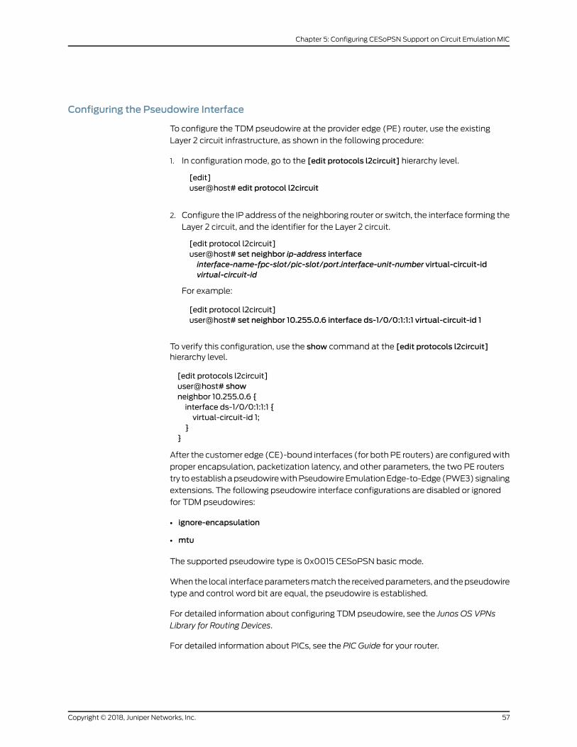
Configuring the Pseudowire Interface
To configure the TDM pseudowire at the provider edge (PE) router, use the existing
Layer 2 circuit infrastructure, as shown in the following procedure:
1. In configuration mode, go to the [edit protocols l2circuit] hierarchy level.
[edit]user@host# edit protocol l2circuit
2. Configure the IP address of the neighboring router or switch, the interface forming the
Layer 2 circuit, and the identifier for the Layer 2 circuit.
[edit protocol l2circuit]user@host# set neighbor ip-address interfaceinterface-name-fpc-slot/pic-slot/port.interface-unit-number virtual-circuit-idvirtual-circuit-id
For example:
[edit protocol l2circuit]user@host# set neighbor 10.255.0.6 interface ds-1/0/0:1:1:1 virtual-circuit-id 1
To verify this configuration, use the show command at the [edit protocols l2circuit]hierarchy level.
[edit protocols l2circuit]user@host# showneighbor 10.255.0.6 {interface ds-1/0/0:1:1:1 {virtual-circuit-id 1;
}}
After the customer edge (CE)-bound interfaces (for bothPE routers) are configuredwith
proper encapsulation, packetization latency, and other parameters, the two PE routers
try toestablishapseudowirewithPseudowireEmulationEdge-to-Edge (PWE3)signaling
extensions. The following pseudowire interface configurations are disabled or ignored
for TDM pseudowires:
• ignore-encapsulation
• mtu
The supported pseudowire type is 0x0015 CESoPSN basic mode.
When the local interfaceparametersmatch the receivedparameters, and thepseudowire
type and control word bit are equal, the pseudowire is established.
For detailed information about configuring TDM pseudowire, see the Junos OS VPNs
Library for Routing Devices.
For detailed information about PICs, see the PIC Guide for your router.
57Copyright © 2018, Juniper Networks, Inc.
Chapter 5: Configuring CESoPSN Support on Circuit Emulation MIC

See Also Setting the Encapsulation Mode on page 54•
• Setting the CESoPSNOptions on page 43
RelatedDocumentation
• Configuring CESoPSN on Channelized OC3/STM1 (Multi-Rate) Circuit Emulation MIC
with SFP on page 45
• Understanding Mobile Backhaul on page 13
Copyright © 2018, Juniper Networks, Inc.58
Circuit Emulation Interfaces Feature Guide for Routing Devices
CHAPTER 6
Configuring ATM Support on CircuitEmulation PICs
• ATM Support on Circuit Emulation PICs Overview on page 59
• Configuring the 4-Port Channelized COC3/STM1 Circuit Emulation PIC on page 62
• Configuring the 12-Port Channelized T1/E1 Circuit Emulation PIC on page 64
• Understanding Inverse Multiplexing for ATM on page 68
• ATM IMA Configuration Overview on page 72
• Configuring ATM IMA on page 79
• Configuring ATM Pseudowires on page 82
• Configuring ATM Cell-Relay Pseudowire on page 84
• ATM Cell Relay Pseudowire VPI/VCI Swapping Overview on page 88
• Configuring ATM Cell-Relay Pseudowire VPI/VCI Swapping on page 89
• Configuring Layer 2 Circuit and Layer 2 VPN Pseudowires on page 95
• Configuring EPD Threshold on page 95
• Configuring ATMQoS or Shaping on page 96
ATMSupport on Circuit Emulation PICs Overview
ThefollowingcomponentssupportATMoverMPLS(RFC4717)andpacketencapsulations
(RFC 2684):
• 4-port COC3/CSTM1 Circuit Emulation PIC on M7i and M10i routers.
• 12-port T1/E1 Circuit Emulation PIC on M7i and M10i routers.
• Channelized OC3/STM1 (Multi-Rate) Circuit Emulation MIC with SFP
(MIC-3D-4COC3-1COC12-CE) on MX Series routers.
• 16-PortChannelizedE1/T1Circuit EmulationMIC(MIC-3D-16CHE1-T1-CE)onMXSeries
routers.
Circuit Emulation PIC ATM configuration and behavior is consistent with existing ATM2
PICs.
59Copyright © 2018, Juniper Networks, Inc.
NOTE: Circuit Emulation PICs require firmware version rom-ce-9.3.pbin or
rom-ce-10.0.pbin for ATM IMA functionality on M7i, M10i, M40e, M120, and
M320 routers running JUNOSOS Release 10.0R1 or later.
• ATMOAM Support on page 60
• Protocol and Encapsulation Support on page 60
• Scaling Support on page 61
• Limitations to ATM Support on Circuit Emulation PICs on page 61
ATMOAMSupport
ATMOAM supports:
• Generation andmonitoring of F4 and F5 OAM cells types:
• F4 AIS (end-to-end)
• F4 RDI (end-to-end)
• F4 loopback (end-to-end)
• F5 loopback
• F5 AIS
• F5 RDI
• Generation andmonitoring of end-to-end cells of type AIS and RDI
• Monitor and terminate loopback cells
• OAM on each VP and VC simultaneously
VP Pseudowires (CCC Encapsulation)—In the case of ATM virtual path (VP)
pseudowires—all virtual circuits (VCs) in a VP are transported over a single N-to-one
mode pseudowire—all F4 and F5 OAM cells are forwarded through the pseudowire.
Port Pseudowires (CCC Encapsulation)—Like VP pseudowires, with port pseudowires,
all F4 and F5 OAM cells are forwarded through the pseudowire.
VC Pseudowires (CCC Encapsulation)—In the case of VC pseudowires, F5 OAM cells are
forwarded through the pseudowire, while F4 OAM cells are terminated at the Routing
Engine.
Protocol and Encapsulation Support
The following protocols are supported:
• QoS or CoS queues. All virtual circuit (VCs) are unspecified bit rate (UBR).
NOTE: This protocol is not supported onM7i andM10i routers.
Copyright © 2018, Juniper Networks, Inc.60
Circuit Emulation Interfaces Feature Guide for Routing Devices
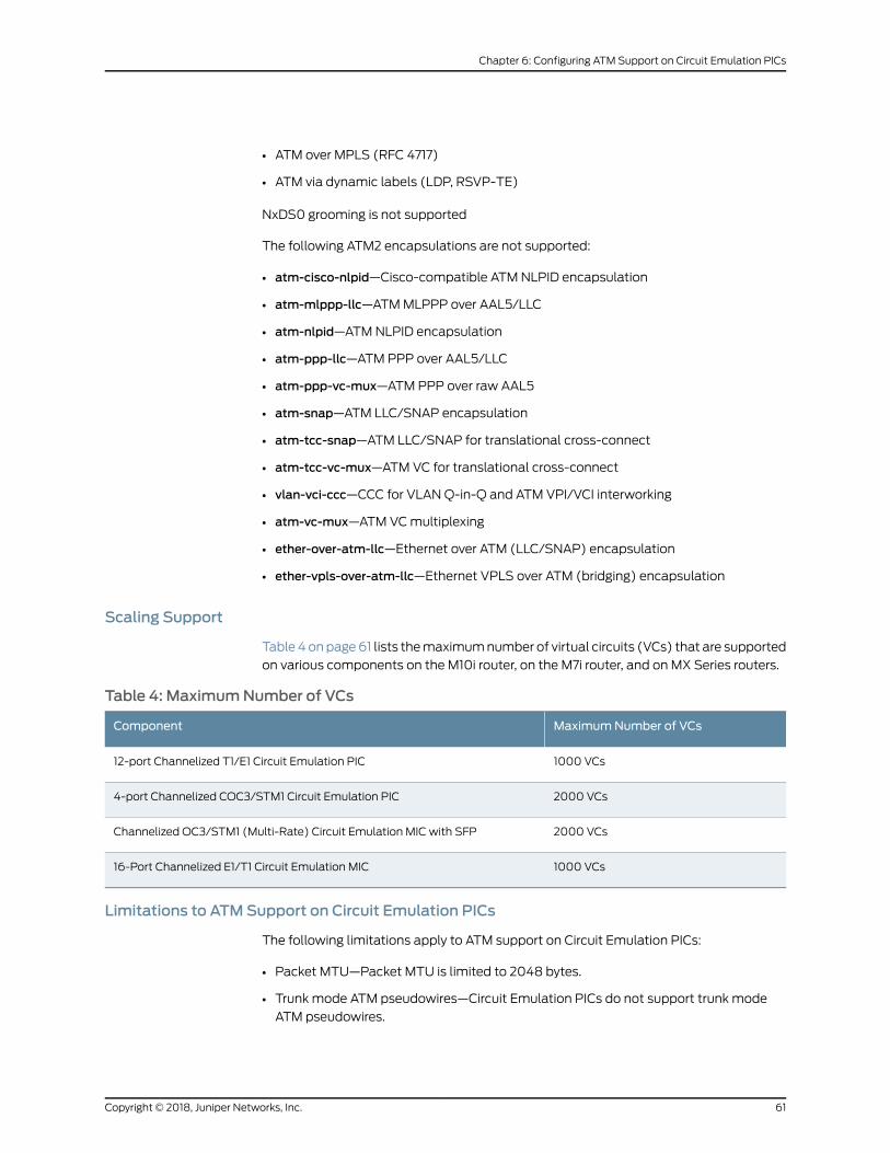
• ATM over MPLS (RFC 4717)
• ATM via dynamic labels (LDP, RSVP-TE)
NxDS0 grooming is not supported
The following ATM2 encapsulations are not supported:
• atm-cisco-nlpid—Cisco-compatible ATM NLPID encapsulation
• atm-mlppp-llc—ATMMLPPP over AAL5/LLC
• atm-nlpid—ATMNLPID encapsulation
• atm-ppp-llc—ATM PPP over AAL5/LLC
• atm-ppp-vc-mux—ATM PPP over raw AAL5
• atm-snap—ATM LLC/SNAP encapsulation
• atm-tcc-snap—ATM LLC/SNAP for translational cross-connect
• atm-tcc-vc-mux—ATM VC for translational cross-connect
• vlan-vci-ccc—CCC for VLAN Q-in-Q and ATM VPI/VCI interworking
• atm-vc-mux—ATM VCmultiplexing
• ether-over-atm-llc—Ethernet over ATM (LLC/SNAP) encapsulation
• ether-vpls-over-atm-llc—Ethernet VPLS over ATM (bridging) encapsulation
Scaling Support
Table 4 onpage61 lists themaximumnumber of virtual circuits (VCs) that are supported
on various components on the M10i router, on the M7i router, and on MX Series routers.
Table 4: MaximumNumber of VCs
MaximumNumber of VCsComponent
1000 VCs12-port Channelized T1/E1 Circuit Emulation PIC
2000 VCs4-port Channelized COC3/STM1 Circuit Emulation PIC
2000 VCsChannelized OC3/STM1 (Multi-Rate) Circuit Emulation MIC with SFP
1000 VCs16-Port Channelized E1/T1 Circuit Emulation MIC
Limitations to ATMSupport on Circuit Emulation PICs
The following limitations apply to ATM support on Circuit Emulation PICs:
• Packet MTU—Packet MTU is limited to 2048 bytes.
• Trunk mode ATM pseudowires—Circuit Emulation PICs do not support trunk mode
ATM pseudowires.
61Copyright © 2018, Juniper Networks, Inc.
Chapter 6: Configuring ATM Support on Circuit Emulation PICs

• OAM-FM segment—Segment F4 flows are not supported. Only end-to-end F4 flows
are supported.
• IP and Ethernet encapsulations—IP and Ethernet encapsulations are not supported.
• F5 OAM—OAM termination is not supported.
RelatedDocumentation
Configuring the 12-Port Channelized T1/E1 Circuit Emulation PIC on page 64•
• Configuring the 4-Port Channelized COC3/STM1 Circuit Emulation PIC on page 62
• ATM IMA Configuration Overview on page 72
• Configuring ATM IMA on page 79
• Configuring ATM Pseudowires on page 82
• Configuring EPD Threshold on page 95
• Configuring Layer 2 Circuit and Layer 2 VPN Pseudowires on page 95
Configuring the 4-Port Channelized COC3/STM1 Circuit Emulation PIC
• T1/E1 Mode Selection on page 62
• ConfiguringaPort forSONETorSDHModeona4-PortChannelizedCOC3/STM1Circuit
Emulation PIC on page 63
• Configuring an ATM Interface on a Channelized OC1 interface on page 64
T1/E1 Mode Selection
All ATM interfaces are either T1 or E1 channels within the COC3/CSTM1 hierarchy. Each
COC3 interface can be partitioned as 3 COC1 slices, each of which in turn can be
partitioned further into 28 ATM interfaces and the size of each interface created is that
of a T1. Each CS1 can be portioned as 1 CAU4,which can be further partitioned as E1 sized
ATM interfaces.
To configure the T1/E1 mode selection, note the following:
1. To create coc3-fpc/pic/port or cstm1-fpc/pic/port interfaces, chassisd will look for
configurationat the [editchassis fpc fpc-slotpicpic-slotportport framing(sonet | sdh)]
hierarchy level. If the sdh option is specified, chassisd will create a cstm1-fpc/pic/port
interface. Otherwise, chassisd will create coc3-fpc/pic/port interfaces.
2. Only interface coc1 can be created from coc3, and t1 can be created from coc1.
3. Only interface cau4 can be created from cstm1, and e1 can be created from cau4.
Figure 5 on page 63 and Figure 6 on page 63 illustrate the possible interfaces that can
be created on the 4-port Channelized COC3/STM1 Circuit Emulation PIC.
Copyright © 2018, Juniper Networks, Inc.62
Circuit Emulation Interfaces Feature Guide for Routing Devices

Figure 5: 4-Port Channelized COC3/STM1 Circuit Emulation PIC PossibleInterfaces (T1 Size)
coc3-x/y/z
coc1-x/y/z:n
t1-x/y/z:n:m at-x/y/z:n:m (T1 size) g017
388
Figure 6: 4-Port Channelized COC3/STM1 Circuit Emulation PIC PossibleInterfaces (E1 Size)
cstm1-x/y/z
cau4-x/y/z
e1-x/y/z:n at-x/y/z:n (E1 size) g017
389
Subrate T1 is not supported.
ATM NxDS0 grooming is not supported.
External and internal loopbackof T1/E1 (on ct1/ce1 physical interfaces) canbe configured
using the sonet-options statement. By default, no loopback is configured.
Configuring a Port for SONET or SDHMode on a 4-Port Channelized COC3/STM1 CircuitEmulation PIC
Each port of the 4-port Channelized COC3/STM1 Circuit Emulation PIC can be
independently configured for either SONET or SDHmode. To configure a port for either
SONETorSDHmode, enter the framing(sonet | sdh) statementat the [chassis fpcnumber
pic number port number] hierarchy level.
The following example shows how to configure FPC 1, PIC 1, and port 0 for SONETmodeand port 1 for SDHmode:
set chassis fpc 1 pic 1 port 0 framing sonetset chassis fpc 1 pic 1 port 1 framing sdh
Or specify the following:
[edit]fpc 1 {pic 1 {port 0 {framing sonet;
}port 1 {framing sdh;
}}
}
63Copyright © 2018, Juniper Networks, Inc.
Chapter 6: Configuring ATM Support on Circuit Emulation PICs
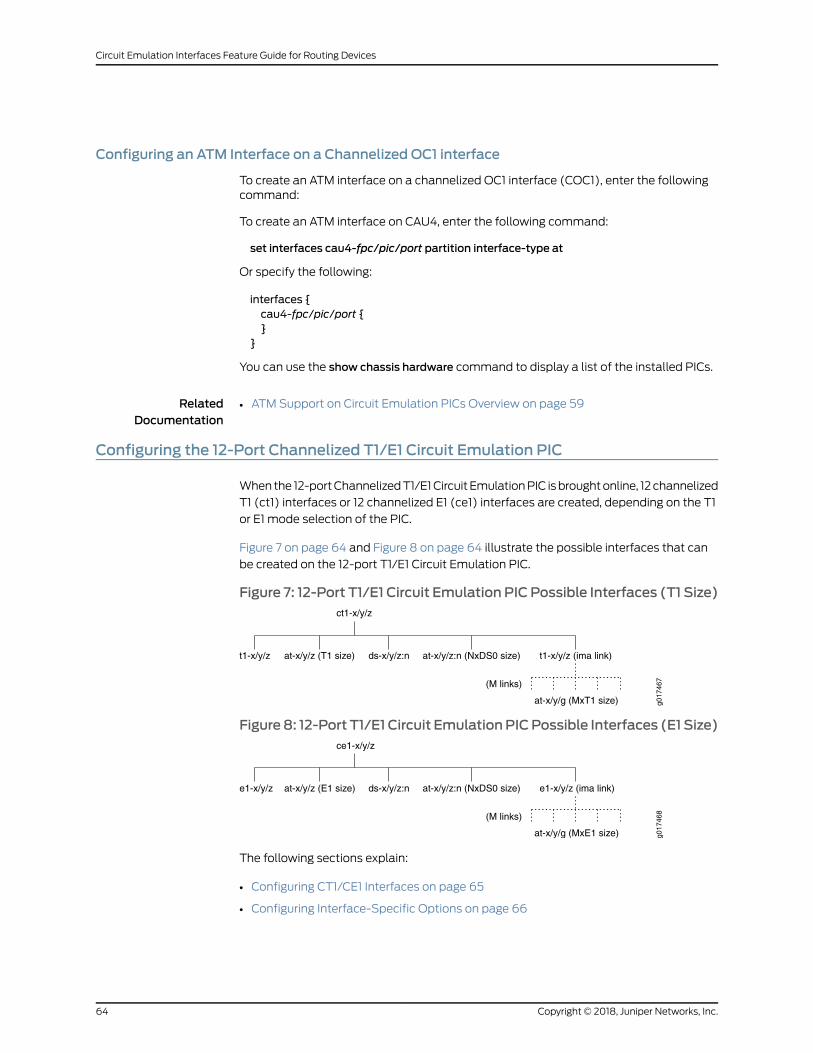
Configuring an ATM Interface on a Channelized OC1 interface
To create an ATM interface on a channelized OC1 interface (COC1), enter the followingcommand:
To create an ATM interface on CAU4, enter the following command:
set interfaces cau4-fpc/pic/port partition interface-type at
Or specify the following:
interfaces {cau4-fpc/pic/port {}
}
You can use the show chassis hardware command to display a list of the installed PICs.
RelatedDocumentation
ATM Support on Circuit Emulation PICs Overview on page 59•
Configuring the 12-Port Channelized T1/E1 Circuit Emulation PIC
Whenthe 12-portChannelizedT1/E1Circuit EmulationPIC isbroughtonline, 12channelized
T1 (ct1) interfaces or 12 channelized E1 (ce1) interfaces are created, depending on the T1
or E1 mode selection of the PIC.
Figure 7 on page 64 and Figure 8 on page 64 illustrate the possible interfaces that can
be created on the 12-port T1/E1 Circuit Emulation PIC.
Figure 7: 12-Port T1/E1 Circuit Emulation PICPossible Interfaces (T1 Size)ct1-x/y/z
t1-x/y/z at-x/y/z (T1 size)g0
1746
7(M links)
ds-x/y/z:n at-x/y/z:n (NxDS0 size) t1-x/y/z (ima link)
at-x/y/g (MxT1 size)
Figure8: 12-Port T1/E1 Circuit EmulationPICPossible Interfaces (E1 Size)ce1-x/y/z
e1-x/y/z at-x/y/z (E1 size)
g017
468(M links)
ds-x/y/z:n at-x/y/z:n (NxDS0 size) e1-x/y/z (ima link)
at-x/y/g (MxE1 size)
The following sections explain:
• Configuring CT1/CE1 Interfaces on page 65
• Configuring Interface-Specific Options on page 66
Copyright © 2018, Juniper Networks, Inc.64
Circuit Emulation Interfaces Feature Guide for Routing Devices
Configuring CT1/CE1 Interfaces
The following sections explain how to configure the T1/E1mode at the PIC level to create
ct1 interfaces or ce1 interfaces and to create an ATM interface on a CT1 interface or a CE1
interface:
• Configuring T1/E1 Mode at the PIC level on page 65
• Creating an ATM Interface on a CT1 or CE1 on page 65
• Creating an ATM Interface on a CE1 Interface on page 66
Configuring T1/E1 Mode at the PIC level
To configure T1/E1 mode at the PIC level:
1. Go to the [edit chassis] hierarchy level.
[edit]user@host# edit chassis
2. Configure the FPC slot and PIC slot.
[edit chassis]user@host# edit fpc fpc-slot pic pic-slot
3. Configure the framingmode as E1 or T1.
[edit chassis fpc fpc-slot pic pic-slot]user@host# edit framing (e1 | t1)
After the PIC is brought online, 12 channelized T1 (ct1) interfaces or 12 channelized E1
(ce1) interfaces are created.
NOTE: If themode is not manually configured, then the PIC defaults to T1.
Creating an ATM Interface on a CT1 or CE1
To create an ATM interface on a CT1 interface:
1. Go to the [edit interfaces ct1-fpc/pic/port] hierarchy level.
[edit]user@host# edit interfaces ct1-fpc/pic/port
2. Configure the no-partition statement to use channelized interface as clear channel
and to set the interface type as an ATM interface.
[edit interfaces ct1-fpc/pic/port]user@host# set no-partition interface-type at
The interface at-fpc/pic/port is created.
65Copyright © 2018, Juniper Networks, Inc.
Chapter 6: Configuring ATM Support on Circuit Emulation PICs
You can use the show chassis hardware command to display a list of the installed PICs.
Creating an ATM Interface on a CE1 Interface
To create an ATM interface on a CE1 interface, enter the following command:
1. Go to the [edit interfaces ce1-fpc/pic/port] hierarchy level.
[edit]iser@host# [edit interfaces ce1-fpc/pic/port]set interfaces no-partition interface-type at
2. Configure the no-partition statement to use channelized interface as clear channel
and to set the interface type as an ATM interface.
[edit interfaces ce1-fpc/pic/port]user@host# set no-partition interface-type at
The interface at-fpc/pic/port is created.
You can use the show chassis hardware command to display a list of the installed PICs.
Configuring Interface-Specific Options
ATM supports T1 and E1 interfaces on 12-port Channelized T1/E1 Circuit Emulation PICs.
The following sections explain how to configure the interface-specific options for ATM,
E1, and T1 interfaces.
• Configuring ATM Interface-Specific Options on page 66
• Configuring E1 Interface-Specific Options on page 67
• Configuring T1 Interface-Specific Options on page 67
Configuring ATM Interface-Specific Options
To configure ATM interface-specific options:
1. Go to the [edit interfaces at-fpc-slot/pic-slot/port:logical-unit].
[edit]user@host# edit interfaces at-fpc-slot/pic-slot/port:logical-unit
2. Configure the supportedPIC type as aCEPIC—atm-ce, a ATM I PIC—atm1, or as aATM
II IQ PIC—atm2 under the atm-options statement.
[edit interfaces at-fpc-slot/pic-slot/port:logical-unit]user@host# edit atm-options (atm-ce | atm1 | atm2)
Copyright © 2018, Juniper Networks, Inc.66
Circuit Emulation Interfaces Feature Guide for Routing Devices
NOTE: To configure Circuit Emulation PICs, youmust specify the pic-type
option as atm-ce at the [edit interfaces at-fpc-slot/pic-slot/port:logical-unit
atm-options] hierarchy level.
OnMX Series routers with ATMMICs with SFP, Junos OS automatically setsthe PIC type to ATMMIC.
Note that this topic uses the term PIC for ATMMICs where the reference isto a CLI or Junos OS entity.
Configuring E1 Interface-Specific Options
To configure E1 interface-specific options:
1. Go to the [edit interfaces at-fpc-slot/pic-slot/port:logical-unit e1-options].
[edit]user@host# edit interfaces at-fpc-slot/pic-slot/port:logical-unit e1-options
2. Configure the framing format for E1 interfaces asG704modewith CRC4—g704, G704
mode without CRC4—g704-no-crc4, or unframedmode—unframed.
[edit interfaces at-fpc-slot/pic-slot/port:logical-unit e1-options]user@host# set framing (g704 | g704-no-crc4 | unframed)
3. Configure the bert-algorithm statement with the pattern to send in the bit stream
during a bit error rate test (BERT).
[edit interfaces at-fpc-slot/pic-slot/port:logical-unit e1-options]user@host# set bert-algorithm algorithm
4. Configure the duration of a BERT test from 1 through 86,400 seconds.
[edit interfaces at-fpc-slot/pic-slot/port:logical-unit e1-options]user@host# set bert-period seconds
5. Configure the loopback mode as local loopback or remote loopback
[edit interfaces at-fpc-slot/pic-slot/port:logical-unit e1-options]user@host# set loopback (local | remote)
Configuring T1 Interface-Specific Options
To configure T1 interface-specific options:
1. Go to the [edit interfaces at-fpc-slot/pic-slot/port:logical-unit t1-options].
[edit]user@host# edit interfaces at-fpc-slot/pic-slot/port:logical-unit t1-options
67Copyright © 2018, Juniper Networks, Inc.
Chapter 6: Configuring ATM Support on Circuit Emulation PICs
2. Configure the framing format for T1 interfaces as extended super frame—esf or super
frame—sf.
[edit interfaces at-fpc-slot/pic-slot/port:logical-unit t1-options]user@host# set framing (esf | sf)
3. Configure the bert-algorithm statement with the pattern to send in the bit stream
during a bit error rate test (BERT).
[edit interfaces at-fpc-slot/pic-slot/port:logical-unit t1-options]user@host# set bert-algorithm algorithm
4. Configure the duration of a BERT test from 1 through 86,400 seconds.
[edit interfaces at-fpc-slot/pic-slot/port:logical-unit t1-options]user@host# set bert-period seconds
5. Configure the loopback mode as local loopback, payload loopback, or remote
loopback.
[edit interfaces at-fpc-slot/pic-slot/port:logical-unit t1-options]user@host# set loopback (local | payload| remote)
6. Configure the CRCminor alarm threshold value.
[edit interfaces at-fpc-slot/pic-slot/port:logical-unit t1-options]user@host# set crc-major-alarm-threshold (1e-3 | 1e-4 | 1e-5 | 1e-6 |5e-4 |5e-5 |5e-6)
7. Configure the CRCmajor alarm threshold value.
[edit interfaces at-fpc-slot/pic-slot/port:logical-unit t1-options]user@host# set crc-major-alarm-threshold (1e-3 | 1e-4 | 1e-5 | 5e-4 | 5e-5)
8. Configure the invert-data statement to invert the transmission of unused data bits on
the T1 interface.
[edit interfaces at-fpc-slot/pic-slot/port:logical-unit t1-options]user@host# set invert-data
RelatedDocumentation
ATM Support on Circuit Emulation PICs Overview on page 59•
Understanding InverseMultiplexing for ATM
Inverse multiplexing for ATM (IMA) is a technique of transporting ATM traffic over a
bundle of T1 or E1 interfaces. The following sections explain IMA in detail:
• Understanding Asynchronous Transfer Mode on page 69
• Understanding Inverse Multiplexing for ATM on page 69
• How Inverse Multiplexing for ATMWorks on page 69
• Supported Platforms on page 71
Copyright © 2018, Juniper Networks, Inc.68
Circuit Emulation Interfaces Feature Guide for Routing Devices
Understanding Asynchronous Transfer Mode
AsynchronousTransferMode (ATM) is a high-speednetworking technology that handles
data in fixed-size units called cells. It enables high-speed communication between edge
routers and core routers in an ATM network.
ATM isdesigned to facilitate thesimultaneoushandlingof various typesof traffic streams
(voice, data, and video) at very high speeds over a dedicated connection. ATM uses
asynchronous time-division multiplexing (TDM) and it encodes data into 53-byte cells,
thereby simplifying the design of hardware and enabling it to quickly determine the
destinationaddressofeachcell. ATMoperatesovereither fiberoptic cablesor twisted-pair
cables. Each ATM PIC is assigned an ATM switch ID that displays the switch’s IP address
and the local interface names of the adjacent Fore ATM switches. For information about
ATM PICs, see the platform-specific Hardware Guide.
ATM relies on the concepts of virtual paths (VPs)andvirtual circuits (VCs). A virtual path,
represented by a specific virtual path identifier (VPI), establishes a route between two
devices in a network. Each VPI can contain multiple VCs, each represented by a virtual
circuit identifier (VCI). VPIs and VCIs are local to the router, which means that only the
two devices connected by the VCI or VPI need know the details of the connection. In a
typicalATMnetwork, userdatamight traversemultiple connections, usingmanydifferent
VPI and VCI connections. Each end device, just like each device in the network, needs to
know only the VCI and VPI information for the path to the next device.
An ATM interface is indicated by the at-fpc/pic/port CLI descriptor.
Understanding InverseMultiplexing for ATM
Inverse multiplexing is a method where a single data stream is divided into multiple
smaller data streams that are transmitted over either fiber optic cables or twisted pair
cablesandare recombinedon theother end to formtheoriginal datastream.This concept
is useful for attaininghigh-speeddata transmission rates.This concepthasbeenextended
to ATM and is called inverse multiplexing for ATM or IMA.
IMA is a technique of transporting ATM traffic over a bundle of T1 or E1 interfaces. IMA
divides a single data stream into multiple smaller data streams, that is transmitted at
the same time across separate channels (such as T1 or E1 interfaces) and then
reconstructed at the other end back into the original data stream.
Two versions of IMA are available–IMA 1.0 (af-phy-0086.000-IMA) and IMA 1.1
(af-phy-0086.001-IMA). You can configure either of these versions, by using the Junos
OS CLI. If not specified, IMA 1.1 is selected by default. Note that IMA 1.0 and IMA 1.1 do not
interoperate.The IMAv1.1 specification increments theOAM(operationsandmaintenance)
label value used in the IMA OAM cells in order to differentiate v1.1 from v1.0 IMA units.
How InverseMultiplexing for ATMWorks
Figure 9 on page 70 displays IMA frames on different links. An IMA frame consists of ATM
cells, an ICP cell, and filler cells (if required).
69Copyright © 2018, Juniper Networks, Inc.
Chapter 6: Configuring ATM Support on Circuit Emulation PICs

Figure 9: IMA Frames on Links
On the transmission side of the ATM IMA network, the ATM cell stream (received from
the ATM layer) is divided across multiple links in an IMA group on a cell by cell basis. On
the receiving end of the ATM IMA network, the cells are recombined to form the original
ATM cells stream (with the help of ICP cells), and then passed on to the ATM layer.
Figure 10 on page 70 displays an IMA frame being transmitted and received through an
IMA group.
Figure 10: IMA Frames Transmitted Through IMAGroup
IMAControl Protocol (ICP) cells are special cells that are sent over theATM IMA interface
with the ATM cell stream to help align the ATM cells at the receiving end. An ICP cell
tracks link differential delay, reduces cell delay variation (CDV), and performs other
functions.
When there are noATMcells to be sent on an IMA frame, the IMA transmitter inserts filler
cells to maintain a continuous stream of cells at the physical layer. The filler cells are
discarded by the IMA receiver. An OAM cell has codes that define it as an ICP cell or a
filler cell.
Copyright © 2018, Juniper Networks, Inc.70
Circuit Emulation Interfaces Feature Guide for Routing Devices
Supported Platforms
The followingare thevarious JuniperNetworks routersand their components that support
inverse multiplexing for ATM (IMA):
• 16-portChannelizedE1/T1Circuit EmulationMIC (MIC-3D-16CHE1-T1-CE)onMXSeries
routers (from Junos OS Release 13.2R1 onward).
• 4-port Channelized OC3/STM1 (Multi-Rate) Circuit Emulation MIC with SFP
(MIC-3D-4COC3-1COC12-CE) on MX Series routers (from Junos OS Release 13.2R1
onward).
• 4-port ChannelizedOC3/STM1Circuit EmulationPICwithSFP (PB-4CHOC3-CE-SFP)
on M7i, M10i, M40e, M120, and M320 routers supports channelized OC3/STM1 (down
to T1) ATM IMA.
• 12-port E1/T1 Circuit Emulation PIC (PB-12T1E1-CE-TELCO) on M7i, M10i, M40e, M120,
and M320 routers supports discrete T1 ATM IMA.
NOTE: Circuit Emulation PICs require firmware version rom-ce-9.3.pbin or
rom-ce-10.0.pbin for ATM IMA functionality on M7i, M10i, M40e, M120, and
M320 routers running Junos OS Release 10.0R1 or later.
RelatedDocumentation
ATM IMA Configuration Overview on page 72•
• ATM Support on Circuit Emulation PICs Overview on page 59
• Configuring ATM IMA on page 79
71Copyright © 2018, Juniper Networks, Inc.
Chapter 6: Configuring ATM Support on Circuit Emulation PICs

ATM IMA Configuration Overview
Inverse multiplexing for ATM (IMA) involves inverse multiplexing and demultiplexing of
ATM cells in a round-robin sequence among links grouped to form a higher-bandwidth
logical link whose rate is the sum of all the link rates. This group of links is called an IMA
group. An IMA group can also be defined as a group of links at the transmitting end that
is used to establish an IMA virtual link to the receiving end. The IMA virtual link is a virtual
link that is established between two IMA units or routers over a number of physical links
(in an IMA group). IMA groups terminate at each end of the IMA virtual link.
You can configure 42 IMA groups. Each group can contain from 1 through 32 links.
You can configure amaximum of 16 IMA groups on the 16-port Channelized E1/T1 Circuit
Emulation MIC (MIC-3D-16CHE1-T1-CE) and each group can have from 1 through 8 IMA
links. Port numbers starting from 0 through 15 are used for T1/E1 ports; therefore, IMA
port numbers start from 16 onward. For information about MIC-3D-16CHE1-T1-CE, see
Channelized E1/T1 Circuit Emulation MIC.
You can configure a maximum of 42 IMA groups on the 4-port Channelized OC3/STM1
(Multi-Rate)Circuit EmulationMICwithSFP(MIC-3D-4COC3-1COC12-CE). The IMAport
numbers start from 16 onward. For information about MIC-3D-4COC3-1COC12-CE, see
Channelized OC3/STM1 (Multi-Rate) Circuit Emulation MIC with SFP.
To configure an IMA group, execute the set chassis fpc fpc-slot pic pic-slot aggregated
devices ima device-count count configuration command, where count results in the
creation of interfaces from at-x/y/g through at-x/y/g+count-1. The variable g is chosen
such that there is no conflictwith non-IMAATM interfaces on the samePIC. For example,
if the count variable is set to 4, then the new ATM interfaces are created from at-x/y/16
through at-x/y/19.
You can implement inverse multiplexing for ATM (IMA) on Juniper Networks routers by
configuring an IMA group and its options. The following sections explain the various
options that can be set for an IMA group:
• IMA Version on page 73
• IMA Frame Length on page 73
• Transmit Clock on page 73
• IMA Group Symmetry on page 73
• Minimum Active Links on page 74
• State Transition Variables: Alpha, Beta, and Gamma on page 74
• IMA Link Addition and Deletion on page 74
• IMA Test Pattern Procedure on page 75
• Per-PIC Limit on the Number of Links on page 75
• IMA Group Alarms and Group Defects on page 76
• IMA Link Alarms and Link Defects on page 77
• IMA Group Statistics on page 78
Copyright © 2018, Juniper Networks, Inc.72
Circuit Emulation Interfaces Feature Guide for Routing Devices

• IMA Link Statistics on page 78
• IMA Clocking on page 79
• Differential Delay on page 79
IMA Version
Either IMA 1.0 (af-phy-0086.000-IMA)or IMA 1.1 (af-phy-0086.001-IMA)canbeselected
through the CLI. To choose the IMA specification version, execute the set interfaces
interface-name ima-group-options (1.0|1.1) configuration command. Note that, if you do
not specify the version, IMA 1.1 is selected by default.
IMA 1.0 and IMA 1.1 do not interoperate.
The IMAv1.1 specification increments theoperationsandmaintenance (OAM) label value
used in the IMA OAM cells in order to differentiate v1.1 from v1.0 IMA units.
IMA Frame Length
An IMA frame consists of ATM cells, an ICP cell, and filler cells (if required). When you
configure an IMA group, you can choose a frame length of 32, 64, 128, or 256. The frame
length can be selected independently in each direction and in each group. To set the
frame length, execute the set interface interface-name frame-length (32 |64 |128 |256)
configuration command. Note that if the frame length is not specified, the frame length
value of 128 is selected by default.
Transmit Clock
When you create an IMAgroup, you can configure a common transmit clock timingmode
or an independent transmit clock timing mode to reflect the primary reference source
(PRS) of the clock for each link in a group. By default, the commonmode is selected. To
select the transmit clock timing mode, execute the set interface interface-name
ima-group-options transmit-clock (common | independent) configuration command.
IMA Group Symmetry
You can configure an IMA group to allow symmetric or asymmetric cell rate transfer over
an IMA virtual link. You can configure the IMA group with one of the following modes:
• Symmetrical configuration and operation—In this mode, on the ATM IMA device, an
IMA link must be configured in each direction for all physical links that the ATM IMA
device is configured to use. In this mode, the ATM IMA device can transmit and receive
ATM layer cells over the physical links onwhich the IMA links running in both directions
are Active.
• Symmetrical configuration and asymmetrical operation—In this mode, on the ATM
IMA device, an IMA link must be configured in each direction for all physical links that
theATM IMAdevice is configured to use. In thismode, theATM IMAdevice can transmit
ATM layer cells over the physical links on which the IMA links in the transmit direction
are Active, while the IMA links in the receive direction are not Active or contrariwise.
Asymmetrical configuration and operation are not supported.
73Copyright © 2018, Juniper Networks, Inc.
Chapter 6: Configuring ATM Support on Circuit Emulation PICs
Themode can be configured through the CLI when an IMA group is created. To select
thesymmetryoption, execute theset interface interface-name ima-group-optionssymmetry
(symmetrical-config-and-operation | symmetrical-config-asymmetrical-operation)
configurationcommand.Bydefault, symmetrical configurationandoperation is selected.
MinimumActive Links
You can set the minimum active links for an IMA group from 1 through 32.
• PTxis the minimum number of links required to be active in the transmit direction for
the IMA group to move into the operational state.
• PRxis theminimumnumber of links required to be active in the receive direction for the
IMA group to move into the operational state.
You configure PTxand P
Rxthrough the CLI when an IMA group is created. By default, 1 is
selected.
For a symmetrical configuration, PTxis equal to P
Rx.
To set minimum links, execute the set interface interface-name ima-group-options
minimum-links links configuration command. By default, symmetrical configuration and
operation is selected.
State Transition Variables: Alpha, Beta, and Gamma
Frame synchronization is a process of recovery of the aggregated frames. The frame
synchronization states form a basis for the different error andmaintenance states. You
canconfigure the IMA framesynchronization link state transition variables asalpha, beta,
and gamma. The valid ranges and default values are shown in Table 5 on page 74.
Table 5: IMA Frame Synchronization Link State Transition Variables
DescriptionDefaultRangeSetting
Consecutive invalid ICP cells21–2alpha
Consecutive errored ICP cells21–5beta
Consecutive valid ICP cells11–5gamma
To set the frame synchronization option, execute the set interface interface-name
ima-group-options frame-synchronization alpha number beta number gamma number
configuration command.
IMA Link Addition and Deletion
When an IMA group is up, you can add links to or delete links from the group without
dropping cells.
Copyright © 2018, Juniper Networks, Inc.74
Circuit Emulation Interfaces Feature Guide for Routing Devices
To create an IMA link, youmust:
• Configure theencapsulationas imaat the [edit interfaces interface-nameencapsulation]
hierarchy level.
• Configure an ATM interface with one T1 link or one E1 link with the set interfaces
interface-name ima-link-options group-id g configuration command.
The interface-name variable refers to the T1 or E1 interface to be set as an IMA interface
link and the variable g refers to the port in the at-x/y/g interface.
To delete the configured IMA link, youmust execute the following configuration
commands:
• delete interfaces interface-name encapsulation ima
• delete interfaces interface-name ima-link-options group g
IMA Test Pattern Procedure
A test pattern procedure is supported for IMA to test the ATM, T1, and E1 interfaces for
irregularities. You can use the CLI to start and end the test pattern procedure.
The following options can be set according to the requirement at the [edit interface
interface-name ima-group-options test-procedure] hierarchy level:
• interface interface-name—Interface name of the IMA link to test.
• pattern number—IMA test pattern that can be set from 1 through 254
• period number—Length of the IMA test pattern that can be set from 1 second through
4,294,967,294 seconds.
To perform the test pattern procedure, execute the test interface interface-name
ima-test-start and test interface interface-name ima-test-stop operational mode
commands to start and to stop the IMA test, respectively.
Per-PIC Limit on the Number of Links
The per-PIC limit on the number of links with the 12-port E1/T1 Circuit Emulation PIC
(PB-12T1E1-CE-TELCO) is up to 12 T1 or E1 links.
The per-PIC limits on the number of links with the 4-port Channelized OC3/STM1 Circuit
Emulation PIC with SFP (PB-4CHOC3-CE-SFP) are:
• T1—0 through 168
• E1—0 through 126
• Mixed: total bandwidth limited to 2xOC3; 258,048,000 bps
The per-PIC limits on the number of links with the 4-port Channelized OC3/STM1
(Multi-Rate) Circuit Emulation MIC with SFP (MIC-3D-4COC3-1COC12-CE) are:
• T1—0 through 336
75Copyright © 2018, Juniper Networks, Inc.
Chapter 6: Configuring ATM Support on Circuit Emulation PICs
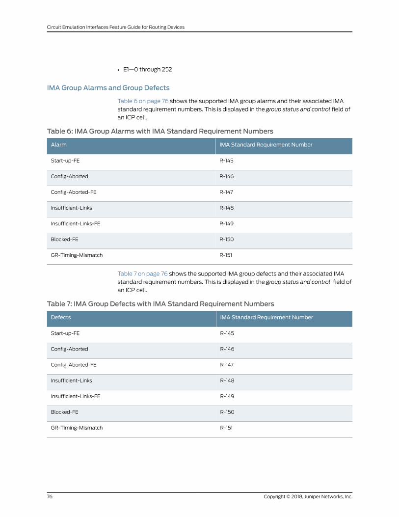
• E1—0 through 252
IMA Group Alarms and Group Defects
Table 6 on page 76 shows the supported IMA group alarms and their associated IMA
standard requirement numbers. This is displayed in the group status and control field of
an ICP cell.
Table 6: IMA Group Alarmswith IMA Standard Requirement Numbers
IMA Standard Requirement NumberAlarm
R-145Start-up-FE
R-146Config-Aborted
R-147Config-Aborted-FE
R-148Insufficient-Links
R-149Insufficient-Links-FE
R-150Blocked-FE
R-151GR-Timing-Mismatch
Table 7 on page 76 shows the supported IMA group defects and their associated IMA
standard requirement numbers. This is displayed in the group status and control field of
an ICP cell.
Table 7: IMA Group Defects with IMA Standard Requirement Numbers
IMA Standard Requirement NumberDefects
R-145Start-up-FE
R-146Config-Aborted
R-147Config-Aborted-FE
R-148Insufficient-Links
R-149Insufficient-Links-FE
R-150Blocked-FE
R-151GR-Timing-Mismatch
Copyright © 2018, Juniper Networks, Inc.76
Circuit Emulation Interfaces Feature Guide for Routing Devices
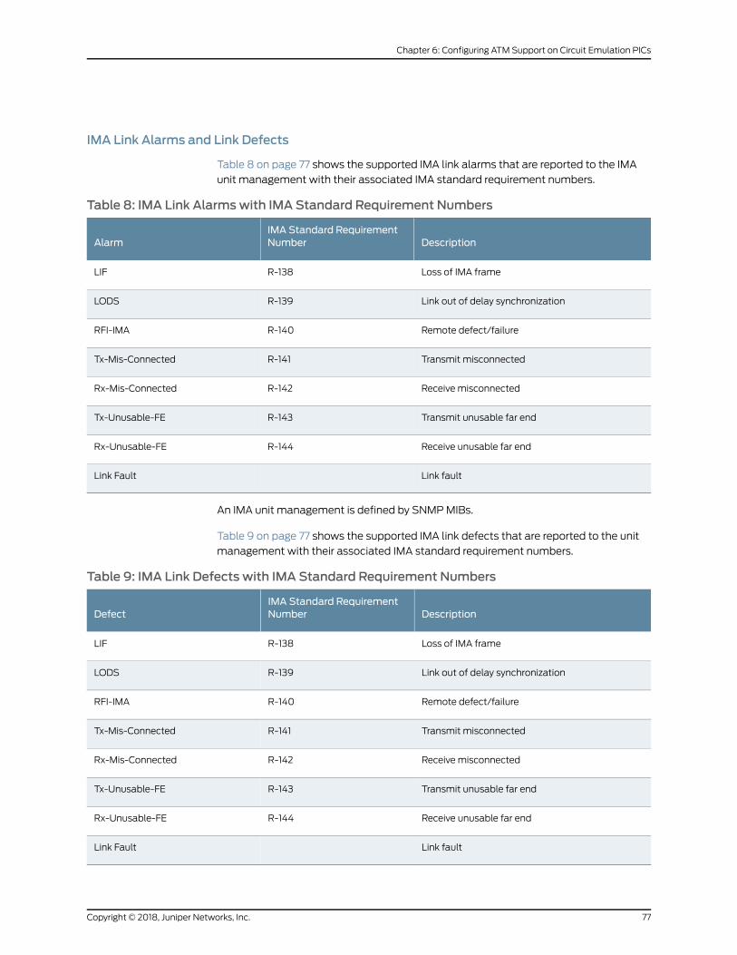
IMA Link Alarms and Link Defects
Table 8 on page 77 shows the supported IMA link alarms that are reported to the IMA
unit management with their associated IMA standard requirement numbers.
Table 8: IMA Link Alarmswith IMA Standard Requirement Numbers
DescriptionIMA Standard RequirementNumberAlarm
Loss of IMA frameR-138LIF
Link out of delay synchronizationR-139LODS
Remote defect/failureR-140RFI-IMA
Transmit misconnectedR-141Tx-Mis-Connected
Receive misconnectedR-142Rx-Mis-Connected
Transmit unusable far endR-143Tx-Unusable-FE
Receive unusable far endR-144Rx-Unusable-FE
Link faultLink Fault
An IMA unit management is defined by SNMPMIBs.
Table 9 on page 77 shows the supported IMA link defects that are reported to the unit
management with their associated IMA standard requirement numbers.
Table 9: IMA Link Defects with IMA Standard Requirement Numbers
DescriptionIMA Standard RequirementNumberDefect
Loss of IMA frameR-138LIF
Link out of delay synchronizationR-139LODS
Remote defect/failureR-140RFI-IMA
Transmit misconnectedR-141Tx-Mis-Connected
Receive misconnectedR-142Rx-Mis-Connected
Transmit unusable far endR-143Tx-Unusable-FE
Receive unusable far endR-144Rx-Unusable-FE
Link faultLink Fault
77Copyright © 2018, Juniper Networks, Inc.
Chapter 6: Configuring ATM Support on Circuit Emulation PICs

IMA Group Statistics
You can use the show interfaces command to display the following IMA group statistics:
• Near-end failure count
• Far-end failure count
• Receive end (Rx) faulty cells due to address mismatch
• Running seconds
• Unavailable seconds
For more information about IMA group statistics, see the show interfaces command
description in the CLI Explorer.
IMA Link Statistics
Table 10 on page 78 shows the IMA link statistics.
Table 10: IMA Link Statistics with IMA Standard Requirement Numbers
IMA Standard Requirement NumberPerformance Parameter
–Rx LIF
–Rx ICP cells
R-106Rx errored ICP cells
R-106Rx LODS
R-107Rx ICP violation
O-17Rx stuff
R-108Near-end Rx SES
R-110Near-end Rx UAS
R-113Near-end Rx UUS
R-117Near-end Rx failure
–Near-end Tx failure
R-109Far-end Rx SES
R-111Far-end Rx UAS
R-115Far-end Rx UUS
Copyright © 2018, Juniper Networks, Inc.78
Circuit Emulation Interfaces Feature Guide for Routing Devices
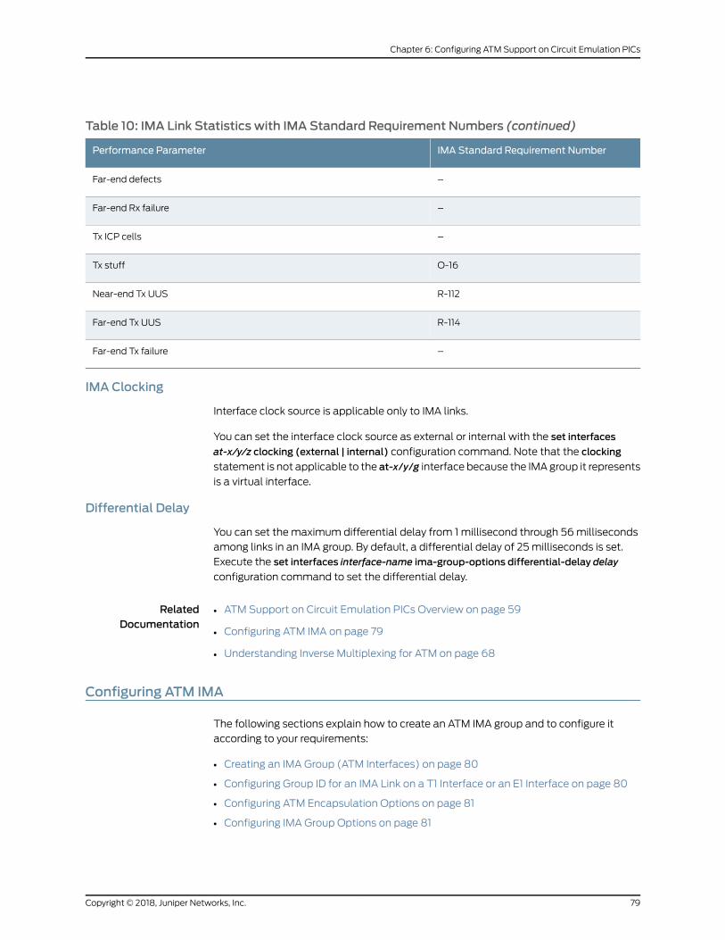
Table 10: IMA Link Statistics with IMA Standard Requirement Numbers (continued)
IMA Standard Requirement NumberPerformance Parameter
–Far-end defects
–Far-end Rx failure
–Tx ICP cells
O-16Tx stuff
R-112Near-end Tx UUS
R-114Far-end Tx UUS
–Far-end Tx failure
IMA Clocking
Interface clock source is applicable only to IMA links.
You can set the interface clock source as external or internal with the set interfaces
at-x/y/z clocking (external | internal) configuration command. Note that the clocking
statement is not applicable to the at-x/y/g interface because the IMAgroup it represents
is a virtual interface.
Differential Delay
You can set the maximum differential delay from 1 millisecond through 56milliseconds
among links in an IMA group. By default, a differential delay of 25milliseconds is set.
Execute the set interfaces interface-name ima-group-options differential-delay delay
configuration command to set the differential delay.
RelatedDocumentation
ATM Support on Circuit Emulation PICs Overview on page 59•
• Configuring ATM IMA on page 79
• Understanding Inverse Multiplexing for ATM on page 68
Configuring ATM IMA
The following sections explain how to create an ATM IMA group and to configure it
according to your requirements:
• Creating an IMA Group (ATM Interfaces) on page 80
• Configuring Group ID for an IMA Link on a T1 Interface or an E1 Interface on page 80
• Configuring ATM Encapsulation Options on page 81
• Configuring IMA Group Options on page 81
79Copyright © 2018, Juniper Networks, Inc.
Chapter 6: Configuring ATM Support on Circuit Emulation PICs

Creating an IMAGroup (ATM Interfaces)
To create an IMA group, perform the following steps:
1. In configuration mode, go to the [edit chassis] hierarchy level:
[edit]user@host# edit chassis
2. Configure the Flexible Port Concentrator (FPC) slot and the Physical Interface Card
(PIC) slot as needed.
[edit chassis]user@host# set fpc fpc-slot pic pic-slot
3. Configure the device count. The device count can be set starting from 1 through 42 in
the aggregated device options for inverse multiplexing for ATM at the [edit chassis
fpc fpc-slot pic pic-slot] hierarchy level.
[edit chassis fpc fpc-slot pic pic-slot]user@host# set aggregated-devices ima device-count count
This results in the creation of interfaces from at-x/y/g through at-x/y/g+count–1, where
the variable count is the number of interfaces and the variable g is chosen such that there
is no conflict with non-IMA at-x/y/z interfaces on the same PIC.
The PIC is automatically rebooted when a configuration that changes the IMA group
count is committed.
Configuring Group ID for an IMA Link on a T1 Interface or an E1 Interface
A group ID is assigned to all links in an IMA group.
To assign a group ID to a T1 or an E1 interface:
1. In configurationmode, go to the [edit interfaces interface-name] hierarchy level, where
the interface name is t1-fpc/pic/port:m:n, e1-fpc/pic/port:n, or t1|e1-fpc/pic/port.
[edit]user@host# edit interface interface-name
2. Configure the encapsulation as ima.
[edit interface interface-name]user@host# set encapsulation ima
3. Configure the IMA group ID from 16 through 57. Note that this group ID is the same for
all T1/E1 interfaces for a particular ATM IMA interface.
[edit interface interface-name]user@host# set ima-link-options group-id number
Copyright © 2018, Juniper Networks, Inc.80
Circuit Emulation Interfaces Feature Guide for Routing Devices
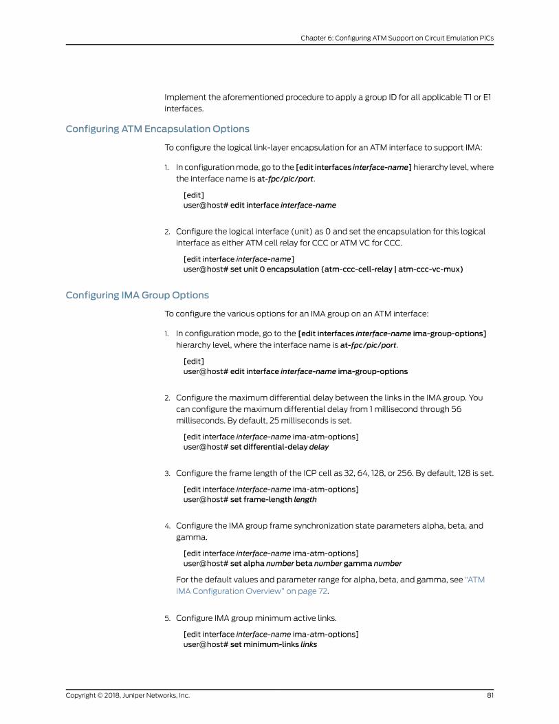
Implement the aforementioned procedure to apply a group ID for all applicable T1 or E1
interfaces.
Configuring ATM Encapsulation Options
To configure the logical link-layer encapsulation for an ATM interface to support IMA:
1. In configurationmode, go to the [edit interfaces interface-name] hierarchy level, where
the interface name is at-fpc/pic/port.
[edit]user@host# edit interface interface-name
2. Configure the logical interface (unit) as 0 and set the encapsulation for this logical
interface as either ATM cell relay for CCC or ATM VC for CCC.
[edit interface interface-name]user@host# set unit 0 encapsulation (atm-ccc-cell-relay | atm-ccc-vc-mux)
Configuring IMAGroup Options
To configure the various options for an IMA group on an ATM interface:
1. In configuration mode, go to the [edit interfaces interface-name ima-group-options]
hierarchy level, where the interface name is at-fpc/pic/port.
[edit]user@host# edit interface interface-name ima-group-options
2. Configure the maximum differential delay between the links in the IMA group. You
can configure the maximum differential delay from 1 millisecond through 56
milliseconds. By default, 25 milliseconds is set.
[edit interface interface-name ima-atm-options]user@host# set differential-delay delay
3. Configure the frame length of the ICP cell as 32, 64, 128, or 256. By default, 128 is set.
[edit interface interface-name ima-atm-options]user@host# set frame-length length
4. Configure the IMA group frame synchronization state parameters alpha, beta, and
gamma.
[edit interface interface-name ima-atm-options]user@host# set alpha number beta number gamma number
For the default values and parameter range for alpha, beta, and gamma, see “ATM
IMA Configuration Overview” on page 72.
5. Configure IMA groupminimum active links.
[edit interface interface-name ima-atm-options]user@host# setminimum-links links
81Copyright © 2018, Juniper Networks, Inc.
Chapter 6: Configuring ATM Support on Circuit Emulation PICs
6. Configure the symmetry of the IMA group as either symmetrical configuration and
operation or symmetrical configuration and asymmetrical operation.
[edit interface interface-name ima-atm-options]user@host# set symmetry (symmetrical-config-and-operation |symmetrical-config-asymmetrical-operation)
For information about symmetry, see “ATM IMA Configuration Overview” on page 72.
7. Configure a test procedure to start and end the test pattern procedure.
[edit interface interface-name ima-atm-options]user@host# set ima-test-startuser@host# ima-test-stopuser@host# interface interface-nameuser@host# pattern numberuser@host# period number
For information about test procedure, see “ATM IMA Configuration Overview” on
page 72.
8. Configure a transmit clock to reflect the primary reference source (PRS) of the clock
for each link in a group either in common timing mode or independent timing mode.
By default, common timing mode is selected.
[edit interface interface-name ima-atm-options]user@host# set transmit-clock (common | independent)
9. Configure the IMA specification version as either version 1.0 or version 1.1. By default,
IMA version 1.1 is selected.
[edit interface interface-name ima-atm-options]user@host# set version (1.0|1.1)
RelatedDocumentation
ATM IMA Configuration Overview on page 72•
• ATM Support on Circuit Emulation PICs Overview on page 59
• Understanding Inverse Multiplexing for ATM on page 68
Configuring ATMPseudowires
ATM pseudowires are described in RFC 4717. Pseudowire encapsulation is selected byconfiguring for a cell-relay pseudowire:
[edit interfaces at-fpc/pic/port:unit n]
encapsulation atm-ccc-cell-relay;atm-l2circuit-mode cell;
Or for an AAL5 pseudowire:
encapsulation atm-ccc-vc-mux;atm-l2circuit-mode aal5;
Copyright © 2018, Juniper Networks, Inc.82
Circuit Emulation Interfaces Feature Guide for Routing Devices
NOTE: encapsulation atm-ccc-cell-relay can be set at either the physical
interface or logical interface level. atm-ccc-vc-mux can only be set at the
logical interface level.
The following sections describe:
• Cell Relay Mode on page 83
• Configuring AAL5 SDUMode on page 84
Cell Relay Mode
In cell relay mode, one or more cells are bundled together to form a packet that is sent
across the PSN tunnel. N-to-onemode is used to encapsulate cell bundles. In thismode,
52 bytes of each cell are transported across the PSN (the HEC field of the ATM header
is omitted). The optional one-to-onemode is not supported.
By default, each ATM cell is encapsulated into a pseudowire packet (per RFC 4717) and
sent over the pseudowire (cell-bundle-size = 1). The pseudowire may be configured to
aggregate a user-configured number of cells into a packet to increase network utilization
efficiency.
[edit interfaces at-fpc/pic/port]atm-options {cell-bundle-size cells;
}
where cells is the number of cells each pseudowire packet should contain.
• Configuring VP or Port Promiscuous Mode on page 83
Configuring VP or Port PromiscuousMode
By default, all incoming cells are mapped from a single VC to an ATM pseudowire. For
ATM physical interfaces configured with atm-l2circuit-mode cell, you can configure port
or VP promiscuous mode.
InVPpromiscuousmode,all cellswith thesameVPIare forwardedonasinglepseudowire:
[edit interfaces at-fpc/pic/port]atm-options {pic-type atm-ce;promiscuous-mode {vpi number;
}}unit 0 {vpi number;
}
In port promiscuousmode, all cells received on a T1 or E1 ATM port are forwarded acrossa single pseudowire:
[edit interfaces at-fpc/pic/port]
83Copyright © 2018, Juniper Networks, Inc.
Chapter 6: Configuring ATM Support on Circuit Emulation PICs
encapsulation atm-ccc-cell-relay;atm-options {pic-type atm-ce;promiscuous-mode
}unit 0 {allow-any-vci;
}
Use the show interface at-x/y/z:n command to view cell relay statistics.
Configuring AAL5 SDUMode
In AAL5 SDUmode, the ATM logical interface (VC) expects all data to be either AAL5
encapsulated packets or OAM cells. AAL5 packets are de-encapsulated (AAL5 trailer is
strippedoff), prependedwithanATMpseudowire controlword (RFC4717)and forwarded
on the pseudowire.
OAM cells that are received while an AAL5 packet is being reassembled are forwarded
on the pseudowire immediately (they are reordered ahead of the packet being
reassembled).
Use the show interface at-x/y/z:n command to view AAL5 statistics.
RelatedDocumentation
ATM Support on Circuit Emulation PICs Overview on page 59•
Configuring ATMCell-Relay Pseudowire
In ATM cell-relay mode, one or more ATM cells are bundled together to form a packet
that is sent across the packet-switched network (PSN) using MPLS. In this mode, each
ATMcell and its header are transported over theMPLS cloud. TheATMheader consisting
of the VPI and VCI values is transported across theMPLS cloud or the backhaul network.
By default, all incoming cells are mapped from a single virtual circuit to an ATM
pseudowire. ForATM logical interfaces configuredwithatm-ccc-cell-relayencapsulation,
youcanconfigureATMcell-relaypseudowire inVP-promiscuousmode,port-promiscuous
mode, and VCCmode.
Promiscuous mode allows you to map all incoming cells from either an interface port or
a virtual path (VP) toa single LSPwithout restricting theVCI number. You canmap traffic
from all 65,535 VCIs to a single LSP, or from all 256 VPIs to a single LSP. For
promiscuous-modeconfigurationguidelines, seeConfiguringATMCell-RelayPromiscuous
Mode.
This topic includes the following tasks:
• Configuring ATM Cell-Relay Pseudowire in Port-Promiscuous Mode on page 85
• Configuring ATM Cell-Relay Pseudowire in VP-Promiscuous Mode on page 85
• Configuring ATM Cell-Relay Pseudowire in VCCMode on page 86
Copyright © 2018, Juniper Networks, Inc.84
Circuit Emulation Interfaces Feature Guide for Routing Devices
Configuring ATMCell-Relay Pseudowire in Port-PromiscuousMode
To configure ATM cell-relay pseudowire in port-promiscuous mode:
1. In configuration mode, go to the [edit interfaces] hierarchy level and set the interface
as at-0/2/2.
[edit]user@host#edit interfaces at-0/2/2
2. Tomap incoming traffic, include the promiscuousmode statement at the [edit
interfaces interface-name atm-options] hierarchy level.
[edit interfaces at-0/2/2]user@host#set atm-options promiscuous-mode
3. To configure ATM encapsulation on unit 0, include the encapsulation statement at
the [edit interfaces interface-name] hierarchy level.
[edit interfaces at-0/2/2]user@host#set unit 0 encapsulation atm-ccc-cell-relay
4. Include the allow-any-vci statement at the [edit interfaces interface-name] hierarchy
level.
[edit interfaces at-0/2/2]user@host#set unit 0 allow-any-vci
5. To verify the configuration, you can issue the following operational mode command
in configuration mode:
[edit]user@host#show at-0/2/2
atm-options{promiscuous-mode;}unit 0{encapsulation atm-ccc-cell-relay;allow-any-vci;}
Configuring ATMCell-Relay Pseudowire in VP-PromiscuousMode
To configure ATM cell-relay pseudowire in VP-promiscuous mode:
1. In configuration mode, go to the [edit interfaces] hierarchy level and set the interface
as at-0/2/2.
[edit]user@host#edit interfaces at-0/2/2
85Copyright © 2018, Juniper Networks, Inc.
Chapter 6: Configuring ATM Support on Circuit Emulation PICs
2. Tomap incoming traffic to a single LSP and to specify the VPI value as 8, include the
promiscuousmode statement and vpi vpi-identifier statement at the [edit interfaces
interface-name atm-options] hierarchy level.
[edit interfaces at-0/2/2]user@host#set atm-options promiscuous-mode vpi 8
3. To configure ATM encapsulation on unit 0, include the encapsulation statement at
the [edit interfaces interface-name] hierarchy level.
[edit interfaces at-0/2/2]user@host#set unit 0 encapsulation atm-ccc-cell-relay
4. To specify 8 as the VPI value on unit 0, include the vpi vpi-identifier statement at the
[edit interfaces interface-name] hierarchy level.
[edit interfaces at-0/2/2]user@host#set unit 0 vpi 8
5. To verify the configuration, you can issue the following operational mode command
in configuration mode:
[edit]user@host#show at-0/2/2
atm-options{vpi 8;promiscuous-mode;}unit 0{encapsulation atm-ccc-cell-relay;vpi 8;}
Configuring ATMCell-Relay Pseudowire in VCCMode
To configure ATM cell-relay pseudowire in VCCmode:
1. In configuration mode, go to the [edit interfaces] hierarchy level and set the interface
as at-0/2/2.
[edit]user@host#edit interfaces at-0/2/2
2. Tomap incoming traffic to a single LSP and to specify the VPI value as 9, include the
promiscuousmode statement and vpi vpi-identifier statement at the [edit interfaces
interface-name atm-options] hierarchy level.
[edit interfaces at-0/2/2]user@host#set atm-options promiscuous-mode vpi 9
3. To configure ATM encapsulation on unit 0, include the encapsulation statement at
the [edit interfaces interface-name] hierarchy level.
Copyright © 2018, Juniper Networks, Inc.86
Circuit Emulation Interfaces Feature Guide for Routing Devices

[edit interfaces at-0/2/2]user@host#set unit 0 encapsulation atm-ccc-cell-relay
4. To specify the VCI value as 9.99 on unit 0, include the vci vci-identifier statement at
the [edit interfaces interface-name] hierarchy level.
[edit interfaces at-0/2/2]user@host#set unit 0 vci 9.99
5. To verify the configuration, you can issue the following operational mode command
in configuration mode:
[edit]user@host#show at-0/2/2
atm-options{vpi 9;promiscuous-mode;}unit 0{encapsulation atm-ccc-cell-relay;vci 9.99;}
RelatedDocumentation
ATM Cell Relay Pseudowire VPI/VCI Swapping Overview on page 88•
• Configuring ATM Cell-Relay Pseudowire VPI/VCI Swapping on page 89
• allow-any-vci
• no-vpivci-swapping on page 117
• psn-vci (ATMCCC Cell-Relay PromiscuousMode VPI/VCI Swapping) on page 118
• psn-vpi (ATMCCC Cell-Relay PromiscuousMode VPI/VCI Swapping) on page 119
• vci
• vpi
87Copyright © 2018, Juniper Networks, Inc.
Chapter 6: Configuring ATM Support on Circuit Emulation PICs
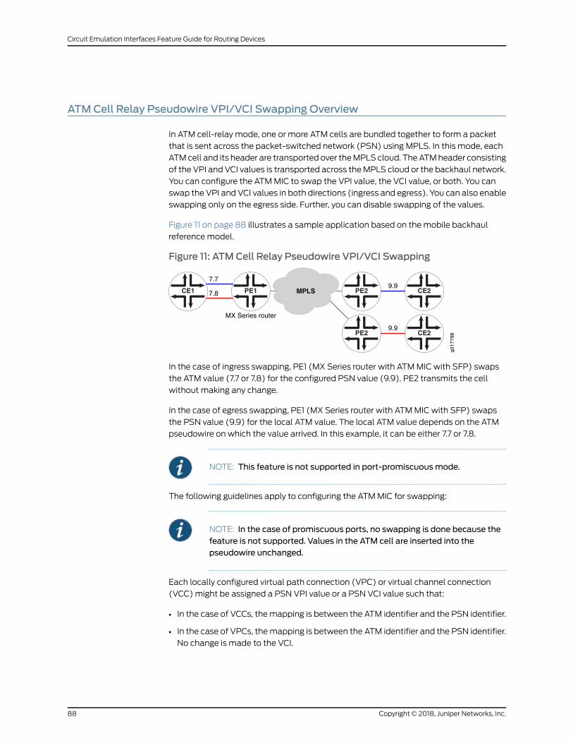
ATMCell Relay Pseudowire VPI/VCI Swapping Overview
In ATM cell-relay mode, one or more ATM cells are bundled together to form a packet
that is sent across the packet-switched network (PSN) using MPLS. In this mode, each
ATMcell and its header are transported over theMPLS cloud. TheATMheader consisting
of the VPI and VCI values is transported across theMPLS cloud or the backhaul network.
You can configure the ATMMIC to swap the VPI value, the VCI value, or both. You can
swap the VPI and VCI values in both directions (ingress and egress). You can also enable
swapping only on the egress side. Further, you can disable swapping of the values.
Figure 11 on page 88 illustrates a sample application based on themobile backhaul
referencemodel.
Figure 11: ATMCell Relay Pseudowire VPI/VCI Swapping
PE2PE1CE1 CE2
g017
798PE2 CE2
MPLS
MX Series router
9.9
9.9
7.7
7.8
In the case of ingress swapping, PE1 (MX Series router with ATMMIC with SFP) swaps
the ATM value (7.7 or 7.8) for the configured PSN value (9.9). PE2 transmits the cell
without making any change.
In the case of egress swapping, PE1 (MX Series router with ATMMIC with SFP) swaps
the PSN value (9.9) for the local ATM value. The local ATM value depends on the ATM
pseudowire on which the value arrived. In this example, it can be either 7.7 or 7.8.
NOTE: This feature is not supported in port-promiscuousmode.
The following guidelines apply to configuring the ATMMIC for swapping:
NOTE: In the case of promiscuous ports, no swapping is done because thefeature is not supported. Values in the ATM cell are inserted into thepseudowire unchanged.
Each locally configured virtual path connection (VPC) or virtual channel connection
(VCC)might be assigned a PSN VPI value or a PSN VCI value such that:
• In the case of VCCs, themapping is between the ATM identifier and the PSN identifier.
• In the case of VPCs, themapping is between the ATM identifier and the PSN identifier.
No change is made to the VCI.
Copyright © 2018, Juniper Networks, Inc.88
Circuit Emulation Interfaces Feature Guide for Routing Devices
The following rule applies when the MIC inserts the VPI or VCI values in the outgoing
pseudowire cell headers—that is, in case of ingress swapping:
• VCCs or promiscuous VPCs—For a given ATM value, the specified PSN identifier is
inserted in the outgoing pseudowire cell header.
If noPSNvalue is specified, then theMICdoesnotperform ingress swapping. The value
inserted in the pseudowire cell header is the one found the in ATM cell.
The following rule applieswhen theMIC inserts theVPI or VCI values in the outgoingATM
cells—that is, in case of egress swapping:
• VCCs or promiscuous VPCs—By default, the MIC performs egress swapping. The ATM
identifier is inserted in the outgoingATMcell irrespective of the value in the pseudowire
cell header. If the no-vpivci-swapping statement is present, no swapping is performed
and the value in the pseudowire is transmitted as is.
RelatedDocumentation
Configuring ATM Cell-Relay Pseudowire VPI/VCI Swapping on page 89•
• no-vpivci-swapping on page 117
• psn-vci on page 118
• psn-vpi on page 119
Configuring ATMCell-Relay Pseudowire VPI/VCI Swapping
Starting in Junos OS Release 12.1, on MX Series routers with ATMMIC with SFP, you can
configure the ATMMIC to swap the VPI value, the VCI value, or both. You can also disable
swapping of the VPI or VCI values. You can opt to swap the VPI and VCI values in both
directions (ingress and egress). You can also enable swapping only on the egress side.
In VPCmode, only the VPI values are swapped.
You can configure the ATMMIC on the local PE router to swap only VPI values in both
directions when the remote PE router does not perform any swapping. If the remote PE
router performs egress swapping by default, you can configure the ATMMIC on the local
PE router to swap only in the egress direction. If you want to disable swapping, you can
configure both the local and remote PE router to disable swapping.
This topic includes the following tasks:
• Configuring VPI Swapping on Egress and Ingress on ATMMICs on page 89
• Configuring Egress Swapping on ATMMICs on page 91
• Disabling Swapping on Local and Remote Provider Edge Routers on page 93
Configuring VPI Swapping on Egress and Ingress on ATMMICs
This procedure describes the steps to configure swapping on the local PE router where
theATMMICswaps inbothdirections (egressand ingress). Youcanalsoexplicitly disable
swapping on the remote PE router.
89Copyright © 2018, Juniper Networks, Inc.
Chapter 6: Configuring ATM Support on Circuit Emulation PICs

NOTE: The configuration included here is specific to VPI or VCI swappinganddoesnot includetheentireATMpseudowireconfiguration.For informationon ATM pseudowire configuration, see “Configuring ATM Cell-RelayPseudowire” on page 84
To configure the local PE router to perform swapping in both directions:
1. To specify the VPI value as 1 on unit 1, include the vpi vpi-identifier statement at the
[edit interfaces interface-name] hierarchy level.
[edit interfaces at-0/2/2]user@host#set unit 1 vpi 1
2. To specify the PSN identifier as 11 on unit 1, include the psn-vpi psn-vpi-identifier
statement at the [edit interfaces interface-name] hierarchy level.
[edit interfaces at-0/2/2 ]user@host#set unit 1 psn-vpi 11
3. To specify the VPI value as 2 on unit 2, include the vpi vpi-identifier statement at the
[edit interfaces interface-name] hierarchy level.
[edit interfaces at-0/2/2]user@host#set unit 2 vpi 2
4. To specify the PSN identifier as 11 on unit 2, include the psn-vpi psn-vpi-identifier
statement at the [edit interfaces interface-name] hierarchy level.
[edit interfaces at-0/2/2 ]user@host#set unit 2 psn-vpi 11
5. To verify the configuration, you can issue the following operational mode command
in configuration mode:
[edit]user@host#show at-0/2/2
..unit 1{vpi 1;psn-vpi 11;}unit 2 {vpi 2;psn-vpi 11;}..
To disable swapping by the remote PE router:
1. To specify the VPI value as 11 on unit 1, include the vpi vpi-identifier statement at the
[edit interfaces interface-name] hierarchy level.
Copyright © 2018, Juniper Networks, Inc.90
Circuit Emulation Interfaces Feature Guide for Routing Devices
[edit interfaces at-0/2/2]user@host#set unit 1 vpi 11
2. Todisable swapping on the remotePE router on unit 1, include the no-vpivci-swapping
statement at the [edit interfaces interface-name] hierarchy level.
[edit interfaces at-0/2/2 ]user@host#set unit 1 no-vpivci-swapping
3. To specify the VPI value as 11 on unit 2, include the vpi vpi-identifier statement at the
[edit interfaces interface-name] hierarchy level.
[edit interfaces at-0/2/2]user@host#set unit 2 vpi 11
4. Todisable swappingon the remotePE router onunit 2, include theno-vpivci-swapping
statement at the [edit interfaces interface-name] hierarchy level.
[edit interfaces at-0/2/2 ]user@host#set unit 2 no-vpivci-swapping
5. To verify the configuration, you can issue the following operational mode command
in configuration mode:
[edit]user@host#show at-0/2/2
..unit 1{vpi 11;no-vpivci-swapping;}unit 2 {vpi 11;no-vpivci-swapping ;}..
Configuring Egress Swapping on ATMMICs
If the remote PE router only performs egress swapping, youmust configure the local PE
router toperformegress swappingaswell. Thisproceduredescribes thesteps toconfigure
egress swapping on both the local and remote PE routers.
NOTE: The configuration included here is specific to VPI or VCI swappinganddoesnot includetheentireATMpseudowireconfiguration.For informationon ATM pseudowire configuration, see “Configuring ATM Cell-RelayPseudowire” on page 84
91Copyright © 2018, Juniper Networks, Inc.
Chapter 6: Configuring ATM Support on Circuit Emulation PICs

To configure the local PE router to perform egress swapping:
1. To specify the VPI value as 1 on unit 1, include the vpi vpi-identifier statement at the
[edit interfaces interface-name] hierarchy level.
[edit interfaces at-0/2/2]user@host#set unit 1 vpi 1
2. To specify the VPI value as 2 on unit 2, include the vpi vpi-identifier statement at the
[edit interfaces interface-name] hierarchy level.
[edit interfaces at-0/2/2]user@host#set unit 2 vpi 2
3. To verify the configuration, you can issue the following operational mode command
in configuration mode:
[edit]user@host#show at-0/2/2
..unit 1{vpi 1;}unit 2 {vpi 2;}..
To configure the remote PE router:
1. To specify the VPI value as 11 on unit 1, include the vpi vpi-identifier statement at the
[edit interfaces interface-name] hierarchy level:
[edit interfaces at-0/2/2]user@host#set unit 1 vpi 11
2. To specify the VPI value as 11 on unit 2, include the vpi vpi-identifier statement at the
[edit interfaces interface-name] hierarchy level:
[edit interfaces at-0/2/2]user@host#set unit 2 vpi 11
3. To verify the configuration, you can issue the following operational mode command
in configuration mode:
[edit]user@host#show at-0/2/2
..unit 1{vpi 11;}unit 2 {vpi 11;
Copyright © 2018, Juniper Networks, Inc.92
Circuit Emulation Interfaces Feature Guide for Routing Devices
}..
Disabling Swapping on Local and Remote Provider Edge Routers
To explicitly disable swapping, youmust use the no-vpivci-swapping statement. When
cell relayofmanyVPCsandVCCshappensover thesamepseudowire, it is recommended
that you explicitly disable swapping. This procedure describes the steps to explicitly
disable swapping on both the local and remote provider edge (PE) routers.
NOTE: The configuration included here is specific to VPI or VCI swappinganddoesnot includetheentireATMpseudowireconfiguration.For informationon ATM pseudowire configuration, see “Configuring ATM Cell-RelayPseudowire” on page 84
To disable swapping on the local PE router:
1. To specify the VPI value as 1 on unit 1, include the vpi vpi-identifier statement at the
[edit interfaces interface-name] hierarchy level.
[edit interfaces at-0/2/2]user@host#set unit 1 vpi 1
2. Todisable swapping, include the no-vpivci-swapping statement at the [edit interfaces
interface-name] hierarchy level.
[edit interfaces at-0/2/2]user@host#set unit 1 no-vpivci-swapping
3. To specify the VPI value as 2 on unit 2, include the vpi vpi-identifier statement at the
[edit interfaces interface-name] hierarchy level.
[edit interfaces at-0/2/2]user@host#set unit 2 vpi 2
4. Todisable swapping, include the no-vpivci-swapping statement at the [edit interfaces
interface-name] hierarchy level.
[edit interfaces at-0/2/2]user@host#set unit 2 no-vpivci-swapping
5. To verify the configuration, you can issue the following operational mode command
in configuration mode:
[edit]user@host#show at-0/2/2
..unit 1{vpi 1;no-vpivci-swapping
93Copyright © 2018, Juniper Networks, Inc.
Chapter 6: Configuring ATM Support on Circuit Emulation PICs

}unit 2{vpi 2;no-vpivci-swapping;}..
To disable swapping on the remote PE router:
1. To specify the VPI value as 1 on unit 1, include the vpi vpi-identifier statement at the
[edit interfaces interface-name] hierarchy level.
[edit interfaces at-0/2/2]user@host#set unit 1 vpi 1
2. To disable swapping on unit 1, include the no-vpivci-swapping statement at the [edit
interfaces interface-name] hierarchy level.
[edit interfaces at-0/2/2]user@host#set unit 1 no-vpivci-swapping
3. To specify the VPI value as 2 on unit 2, include the vpi vpi-identifier statement at the
[edit interfaces interface-name] hierarchy level.
[edit interfaces at-0/2/2]user@host#set unit 2 vpi 2
4. To disable swapping on unit 2, include the no-vpivci-swapping statement at the [edit
interfaces interface-name] hierarchy level.
[edit interfaces at-0/2/2]user@host#set unit 2 no-vpivci-swapping
5. To verify the configuration, you can issue the following operational mode command
in configuration mode:
[edit]user@host#show at-0/2/2
..unit 1{vpi 1;no-vpivci-swapping;}unit 2 {vpi 2;no-vpivci-swapping;}..
RelatedDocumentation
ATM Cell Relay Pseudowire VPI/VCI Swapping Overview on page 88•
• allow-any-vci
Copyright © 2018, Juniper Networks, Inc.94
Circuit Emulation Interfaces Feature Guide for Routing Devices
• no-vpivci-swapping on page 117
• psn-vci on page 118
• psn-vpi on page 119
• vci
• vpi
Configuring Layer 2 Circuit and Layer 2 VPN Pseudowires
ATM Layer 2 circuit and Layer 2 VPN pseudowires are configured using the same syntax
described for ATM2 PICs.
To configure an ATM Layer 2 circuit and a Layer 2 VPN pseudowire.
1. Go to the [edit protocols] hierarchy level.
[edit]user@host# edit protocols
2. Configure a Layer 2 circuit over MPLS with a neighbor IP address (that is loopback
address on the remote router) with the interface name (that is, the Circuit Emulation
PIC ATM interface configured for CCC encapsulation).
[edit protocols]user@host# edit l2circuit neighbor ip-address interface interface-name
3. Configure a virtual circuit identifier for this Layer 2 circuit from 1 through4294,967,295.
[edit protocols l2circuit neighbor ip-address interface interface-name]user@host# set virtual-circuit-id id
Configure the MPLS parameters and the other routing configuration as needed.
RelatedDocumentation
ATM Support on Circuit Emulation PICs Overview on page 59•
Configuring EPD Threshold
ATMencapsulationsprovidecongestioncontrol via early packetdiscard (EPD) thresholds
on a per logical interface basis. For Circuit Emulation PICs, the EPD number specifies the
numberofpackets (or framesor cell bundles). TheEPDthreshold is a limit on thenumber
of transmit packets that can be queued. Packets that exceed the limit are discarded. For
ATM2 IQ interfaces only, youmust define the EPD threshold on a virtual circuit (VC).
To configure EPD threshold.
1. Go to the [edit interfaces at-fpc/pic/port] hierarchy level.
[edit]user@host# edit interfaces at-fpc/pic/port
95Copyright © 2018, Juniper Networks, Inc.
Chapter 6: Configuring ATM Support on Circuit Emulation PICs

2. Configure a name for the scheduler-maps statement in the ATM interface-specific
options.
[edit interfaces at-fpc/pic/port ]user@host# edit atm-options scheduler-mapsmap-name
3. Configure a forwarding class namewhich acts as a scheduling parameter associated
with the forwarding class.
[edit interfaces at-fpc/pic/port atm-options scheduler-mapsmap-name]user@host# edit forwarding-class class-name
4. Configure an EPD threshold value and an EPD threshold value for PLP 1.
[edit interfaces at-fpc/pic/port atm-options scheduler-mapsmap-nameforwarding-class class-name]
user@host# set epd-threshold cells plp1 cells
RelatedDocumentation
ATM Support on Circuit Emulation PICs Overview on page 59•
Configuring ATMQoS or Shaping
M7i, M10i, M40e, M120, and M320 routers with 4-port channelized OC3/STM1 Circuit
Emulation PICs and 12-port T1/E1 Circuit Emulation PICs and MX Series routers with
Channelized OC3/STM1 (Multi-Rate) Circuit Emulation MIC with SFP and 16-Port
Channelized E1/T1 Circuit Emulation MIC support ATM pseudowire service with QoS
features for ingress and egress direction traffic shaping. Policing is performed by
monitoring the configured parameters on the incoming traffic and is also referred to as
ingress shaping. Egress shaping uses queuing and scheduling to shape the outgoing
traffic. Classification is provided per virtual circuit (VC).
To configure QoS shaping for Circuit Emulation PICs, use the shaping statement and its
subordinate statementsat the [edit interfacesat-fpc/pic/portunitn]hierarchy level.Most
Circuit Emulation PIC QoS CLI commands are similar to those used for the ATM2 PIC
QoS features. The interface configuration is sent to the PIC and the PIC driver configures
the PIC appropriately.
Example: Shaping forLogical Interfaces in
Shaping for logical interfaces inport promiscuousmode is configuredunder the followinghierarchy:
interfaces {Port Promiscuous
Mode at-fpc/pic/port{atm-options {pic-type atm-ce;promiscuous-mode {vpi 0;vpi 1;
}}unit 0 {encapsulation atm-ccc-cell-relay;
Copyright © 2018, Juniper Networks, Inc.96
Circuit Emulation Interfaces Feature Guide for Routing Devices
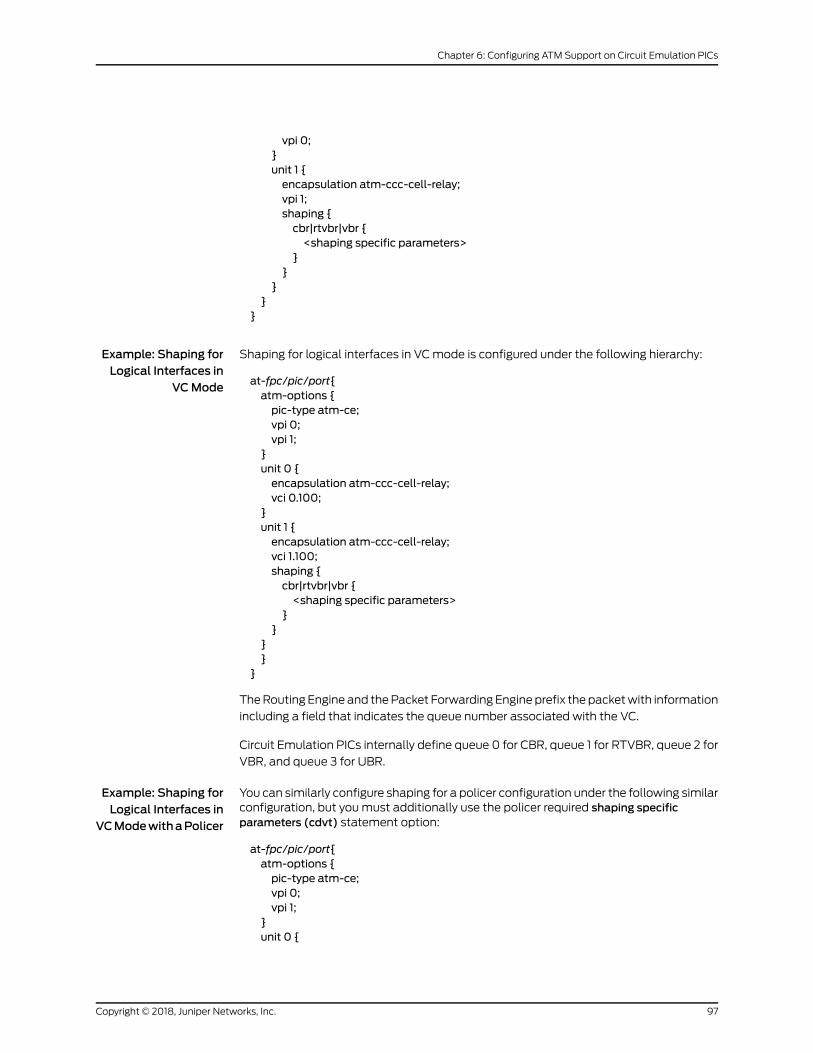
vpi 0;}unit 1 {encapsulation atm-ccc-cell-relay;vpi 1;shaping {cbr|rtvbr|vbr {<shaping specific parameters>
}}
}}
}
Example: Shaping forLogical Interfaces in
VCMode
Shaping for logical interfaces in VCmode is configured under the following hierarchy:
at-fpc/pic/port{atm-options {pic-type atm-ce;vpi 0;vpi 1;
}unit 0 {encapsulation atm-ccc-cell-relay;vci 0.100;
}unit 1 {encapsulation atm-ccc-cell-relay;vci 1.100;shaping {cbr|rtvbr|vbr {<shaping specific parameters>
}}
}}
}
TheRouting Engine and thePacket Forwarding Engine prefix the packetwith information
including a field that indicates the queue number associated with the VC.
Circuit Emulation PICs internally define queue 0 for CBR, queue 1 for RTVBR, queue 2 for
VBR, and queue 3 for UBR.
Example: Shaping forLogical Interfaces in
VCModewithaPolicer
You can similarly configure shaping for a policer configuration under the following similarconfiguration, but youmust additionally use the policer required shaping specificparameters (cdvt) statement option:
at-fpc/pic/port{atm-options {pic-type atm-ce;vpi 0;vpi 1;
}unit 0 {
97Copyright © 2018, Juniper Networks, Inc.
Chapter 6: Configuring ATM Support on Circuit Emulation PICs
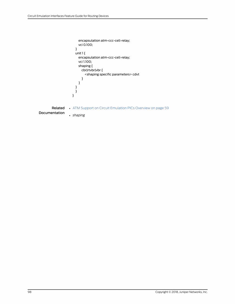
encapsulation atm-ccc-cell-relay;vci 0.100;
}unit 1 {encapsulation atm-ccc-cell-relay;vci 1.100;shaping {cbr|rtvbr|vbr {<shaping specific parameters> cdvt
}}
}}
}
RelatedDocumentation
• ATM Support on Circuit Emulation PICs Overview on page 59
• shaping
Copyright © 2018, Juniper Networks, Inc.98
Circuit Emulation Interfaces Feature Guide for Routing Devices

PART 3
Troubleshooting Information
• Troubleshooting Circuit Emulation Interfaces on page 101
99Copyright © 2018, Juniper Networks, Inc.

Copyright © 2018, Juniper Networks, Inc.100
Circuit Emulation Interfaces Feature Guide for Routing Devices

CHAPTER 7
Troubleshooting Circuit EmulationInterfaces
• Displaying Information About Circuit Emulation PICs on page 101
• Configuring Interface Diagnostics Tools to Test the Physical Layer
Connections on page 101
Displaying Information About Circuit Emulation PICs
Use the CLI show chassis hardware command to display information about the PIC
configuration.
• For a T1 Circuit Emulation PIC configuration, the output designation is T1 CE.
• For an E1 Circuit Emulation PIC configuration, the output designation is E1 CE.
• For a COC3 Circuit Emulation PIC configuration, the output designation is COC1 CE.
• For a CSTM1 Circuit Emulation PIC configuration, the output designation is CSTM1 CE.
• For a OC3/STM1 or OC12/STM4 Circuit Emulation ATMMIC configuration, the output
designation is 2xOC12/8xOC3 CC-CE.
RelatedDocumentation
Understanding Circuit Emulation Services and the Supported PIC Types on page 3•
• Configuring the 4-Port Channelized COC3/STM1 Circuit Emulation PIC on page 62
• Configuring the 12-Port Channelized T1/E1 Circuit Emulation PIC on page 64
Configuring Interface Diagnostics Tools to Test the Physical Layer Connections
• Configuring Loopback Testing on page 102
• Configuring BERT Testing on page 104
• Starting and Stopping a BERT Test on page 107
101Copyright © 2018, Juniper Networks, Inc.
Configuring Loopback Testing
Loopback testing allows you to verify the connectivity of a circuit. You can configure any
of the following interfaces toexecutea loopback test: aggregatedEthernet, Fast Ethernet,
Gigabit Ethernet, E1, E3, NxDS0, serial, SONET/SDH, T1, and T3.
The physical path of a network data circuit usually consists of segments interconnected
by devices that repeat and regenerate the transmission signal. The transmit path on one
device connects to the receive path on the next device. If a circuit fault occurs in the form
of a line break or a signal corruption, you can isolate the problem by using a loopback
test. Loopback testsallowyou to isolate segmentsof thecircuit and test themseparately.
To do this, configure a line loopback on one of the routers. Instead of transmitting the
signal toward the far-enddevice, the line loopback sends the signal back to theoriginating
router. If the originating router receives back its own Data Link Layer packets, you have
verified that the problem is beyond the originating router. Next, configure a line loopback
farther away from the local router. If this originating router does not receive its own Data
Link Layer packets, you can assume that the problem is on one of the segments between
the local router and the remote router’s interface card. In this case, the next
troubleshooting step is to configure a line loopback closer to the local router to find the
source of the problem.
The following types of loopback testing are supported by Junos OS:
• DCE local—Loopspacketsbackon the localdatacircuit-terminatingequipment (DCE).
• DCE remote—Loops packets back on the remote DCE.
• Local—Useful for troubleshooting physical PIC errors. Configuring local loopback on
an interface allows transmission of packets to the channel service unit (CSU) and then
to the circuit toward the far-end device. The interface receives its own transmission,
which includesdataand timing information, on the local router'sPIC.Thedata received
from the CSU is ignored. To test a local loopback, issue the show interfaces
interface-name command. If PPP keepalives transmitted on the interface are received
by the PIC, the Device Flags field contains the output Loop-Detected.
• Payload—Useful for troubleshooting the physical circuit problems between the local
router and the remote router. A payload loopback loops data only (without clocking
information) on the remote router’s PIC. With payload loopback, overhead is
recalculated.
• Remote—Useful for troubleshooting the physical circuit problems between the local
router and the remote router. A remote loopback loops packets, including both data
and timing information, back on the remote router’s interface card. A router at one end
of thecircuit initiatesa remote loopback toward its remotepartner.Whenyouconfigure
a remote loopback, thepackets received fromthephysical circuit andCSUare received
by the interface. Those packets are then retransmitted by the PIC back toward the
CSU and the circuit. This loopback tests all the intermediate transmission segments.
Table 11 onpage 103shows the loopbackmodessupportedon thevarious interface types.
Copyright © 2018, Juniper Networks, Inc.102
Circuit Emulation Interfaces Feature Guide for Routing Devices

Table 11: LoopbackModes by Interface Type
Usage GuidelinesLoopback ModesInterface
Configuring Ethernet Loopback CapabilityLocalAggregated Ethernet,Fast Ethernet, GigabitEthernet
Configuring E1 Loopback CapabilityLocal and remoteCircuit Emulation E1
Configuring T1 Loopback CapabilityLocal and remoteCircuit Emulation T1
Configuring E1 Loopback Capability andConfiguring E3 Loopback Capability
Local and remoteE1 and E3
Configuring NxDS0 IQ and IQE Interfaces,ConfiguringT1andNxDS0 Interfaces,ConfiguringChannelized OC12/STM4 IQ and IQE Interfaces(SONETMode),Configuring Fractional E1 IQandIQE Interfaces, and Configuring Channelized T3IQ Interfaces
PayloadNxDS0
Configuring Serial Loopback CapabilityLocal and remoteSerial (V.35 and X.21)
Configuring Serial Loopback CapabilityDCE local, DCEremote, local, andremote
Serial (EIA-530)
Configuring SONET/SDH Loopback Capabilityto Identify a Problem as Internal or External
Local and remoteSONET/SDH
Configuring T1 Loopback Capability andConfiguring T3 Loopback Capability
See also Configuring the T1 Remote LoopbackResponse
Local, payload, andremote
T1 and T3
To configure loopback testing, include the loopback statement:
user@host# loopbackmode;
You can include this statement at the following hierarchy levels:
• [edit interfaces interface-name aggregated-ether-options]
• [edit interfaces interface-name ds0-options]
• [edit interfaces interface-name e1-options]
• [edit interfaces interface-name e3-options]
• [edit interfaces interface-name fastether-options]
• [edit interfaces interface-name gigether-options]
• [edit interfaces interface-name serial-options]
103Copyright © 2018, Juniper Networks, Inc.
Chapter 7: Troubleshooting Circuit Emulation Interfaces

• [edit interfaces interface-name sonet-options]
• [edit interfaces interface-name t1-options]
• [edit interfaces interface-name t3-options]
Configuring BERT Testing
To configure BERT:
• Configure the duration of the test.
[edit interfaces interface-name interface-type-options]user@host#bert-period seconds;
You can configure the BERT period to last from 1 through 239 seconds on some PICs
and from1 through240secondsonotherPICs.Bydefault, theBERTperiod is 10seconds.
• Configure the error rate to monitor when the inbound pattern is received.
[edit interfaces interface-name interface-type-options]user@host#bert-error-rate rate;
rate is the bit error rate. This can be an integer from 0 through 7, which corresponds to
a bit error rate from 10–0(1 error per bit) to 10
–7(1 error per 10 million bits).
• Configure the bit pattern to send on the transmit path.
[edit interfaces interface-name interface-type-options]user@host#bert-algorithm algorithm;
algorithm is the pattern to send in the bit stream. For a list of supported algorithms,
enter a ? after the bert-algorithm statement; for example:
[edit interfaces t1-0/0/0 t1-options]
user@host# set bert-algorithm ?Possible completions: pseudo-2e11-o152 Pattern is 2^11 -1 (per O.152 standard) pseudo-2e15-o151 Pattern is 2^15 - 1 (per O.152 standard) pseudo-2e20-o151 Pattern is 2^20 - 1 (per O.151 standard) pseudo-2e20-o153 Pattern is 2^20 - 1 (per O.153 standard) ...
For specific hierarchy information, see the individual interface types.
NOTE: The four-port E1 PIC supports only the following algorithms:
pseudo-2e11-o152 Pattern is 2^11 -1 (per O.152 standard) pseudo-2e15-o151 Pattern is 2^15 - 1 (per O.151 standard) pseudo-2e20-o151 Pattern is 2^20 - 1 (per O.151 standard) pseudo-2e23-o151 Pattern is 2^23 (per O.151 standard)
When you issue the help command from the CLI, all BERT algorithm options
are displayed, regardless of the PIC type, and no commit check is available.Unsupported patterns for a PIC type can be viewed in system logmessages.
Copyright © 2018, Juniper Networks, Inc.104
Circuit Emulation Interfaces Feature Guide for Routing Devices

NOTE: The 12-port T1/E1 Circuit Emulation (CE) PIC supports only thefollowing algorithms:
all-ones-repeating Repeating one bits all-zeros-repeating Repeating zero bits alternating-double-ones-zeros Alternating pairs of ones and zeros alternating-ones-zeros Alternating ones and zeros pseudo-2e11-o152 Pattern is 2^11 -1 (per O.152 standard) pseudo-2e15-o151 Pattern is 2^15 - 1 (per O.151 standard) pseudo-2e20-o151 Pattern is 2^20 - 1 (per O.151 standard) pseudo-2e7 Pattern is 2^7 - 1 pseudo-2e9-o153 Pattern is 2^9 - 1 (per O.153 standard) repeating-1-in-4 1 bit in 4 is set repeating-1-in-8 1 bit in 8 is set repeating-3-in-24 3 bits in 24 are set
When you issue the help command from the CLI, all BERT algorithm options
are displayed, regardless of the PIC type, and no commit check is available.Unsupported patterns for a PIC type can be viewed in system logmessages.
NOTE: The IQE PICs support only the following algorithms:
all-ones-repeating Repeating one bitsall-zeros-repeating Repeating zero bitsalternating-double-ones-zeros Alternating pairs of ones and zerosalternating-ones-zeros Alternating ones and zerospseudo-2e9-o153 Pattern is 2^9 -1 (per O.153 (511 type) standard)pseudo-2e11-o152 Pattern is 2^11 -1 (per O.152 and O.153 (2047 type) standards)pseudo-2e15-o151 Pattern is 2^15 -1 (per O.151 standard)pseudo-2e20-o151 Pattern is 2^20 -1 (per O.151 standard)pseudo-2e20-o153 Pattern is 2^20 -1 (per O.153 standard)pseudo-2e23-o151 Pattern is 2^23 -1 (per O.151 standard)repeating-1-in-4 1 bit in 4 is setrepeating-1-in-8 1 bit in 8 is setrepeating-3-in-24 3 bits in 24 are set
When you issue the help command from the CLI, all BERT algorithm options
are displayed, regardless of the PIC type, and no commit check is available.Unsupported patterns for a PIC type can be viewed in system logmessages.
105Copyright © 2018, Juniper Networks, Inc.
Chapter 7: Troubleshooting Circuit Emulation Interfaces
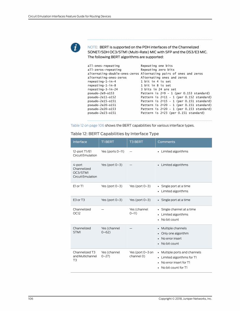
NOTE: BERT is supported on the PDH interfaces of the ChannelizedSONET/SDHOC3/STM1 (Multi-Rate) MIC with SFP and the DS3/E3MIC.The following BERT algorithms are supported:
all-ones-repeating Repeating one bitsall-zeros-repeating Repeating zero bitsalternating-double-ones-zeros Alternating pairs of ones and zerosalternating-ones-zeros Alternating ones and zerosrepeating-1-in-4 1 bit in 4 is setrepeating-1-in-8 1 bit in 8 is setrepeating-3-in-24 3 bits in 24 are setpseudo-2e9-o153 Pattern is 2^9 - 1 (per O.153 standard)pseudo-2e11-o152 Pattern is 2^11 - 1 (per O.152 standard)pseudo-2e15-o151 Pattern is 2^15 - 1 (per O.151 standard)pseudo-2e20-o151 Pattern is 2^20 - 1 (per O.151 standard)pseudo-2e20-o153 Pattern is 2^20 - 1 (per O.153 standard)pseudo-2e23-o151 Pattern is 2^23 (per O.151 standard)
Table 12 on page 106 shows the BERT capabilities for various interface types.
Table 12: BERT Capabilities by Interface Type
CommentsT3 BERTT1 BERTInterface
• Limited algorithms—Yes (ports 0–11)12-port T1/E1CircuitEmulation
• Limited algorithms—Yes (port 0–3)4-portChannelizedOC3/STM1CircuitEmulation
• Single port at a time
• Limited algorithms
Yes (port 0–3)Yes (port 0–3)E1 or T1
• Single port at a timeYes (port 0–3)Yes (port 0–3)E3 or T3
• Single channel at a time
• Limited algorithms
• No bit count
Yes (channel0–11)
—ChannelizedOC12
• Multiple channels
• Only one algorithm
• No error insert
• No bit count
—Yes (channel0–62)
ChannelizedSTM1
• Multiple ports and channels
• Limited algorithms for T1
• No error insert for T1
• No bit count for T1
Yes (port 0–3 onchannel 0)
Yes (channel0–27)
Channelized T3andMultichannelT3
Copyright © 2018, Juniper Networks, Inc.106
Circuit Emulation Interfaces Feature Guide for Routing Devices

These limitations do not apply to channelized IQ interfaces. For information about BERT
capabilities onchannelized IQ interfaces, seeChannelized IQand IQE InterfacesProperties.
Starting and Stopping a BERT Test
Before you can start the BERT test, youmust disable the interface. To do this, include
the disable statement at the [edit interfaces interface-name] hierarchy level:
[edit interfaces interface-name]disable;
After you configure the BERT properties and commit the configuration, begin the test by
issuing the test interface interface-name interface-type-bert-start operational mode
command:
user@host> test interface interface-name interface-type-bert-start
The test runs for the duration you specify with the bert-period statement. If you want to
terminate the test sooner, issue the test interface interface-name interface-type-bert-stop
command:
user@host> test interface interface-name interface-type-bert-stop
For example:
user@host> test interface t3-1/2/0 t3-bert-startuser@host> test interface t3-1/2/0 t3-bert-stop
To view the results of the BERT test, issue the show interfaces extensive | find BERT
command:
user@host> show interfaces interface-name extensive | find BERT
For more information about running and evaluating the results of the BERT procedure,
see the CLI Explorer.
NOTE: To exchange BERT patterns between a local router and a remoterouter, include the loopback remote statement in the interface configuration
at the remote end of the link. From the local router, issue the test interface
command.
RelatedDocumentation
• show interfaces diagnostics optics (Gigabit Ethernet, 10-Gigabit Ethernet, 40-Gigabit
Ethernet, 100-Gigabit Ethernet, and Virtual Chassis Port)
107Copyright © 2018, Juniper Networks, Inc.
Chapter 7: Troubleshooting Circuit Emulation Interfaces

Copyright © 2018, Juniper Networks, Inc.108
Circuit Emulation Interfaces Feature Guide for Routing Devices

PART 4
Configuration Statements andOperational Commands
• Configuration Statements on page 111
• Operational Commands on page 123
109Copyright © 2018, Juniper Networks, Inc.

Copyright © 2018, Juniper Networks, Inc.110
Circuit Emulation Interfaces Feature Guide for Routing Devices
CHAPTER 8
Configuration Statements
• cesopsn-options on page 112
• event (CFM) on page 113
• fast-aps-switch on page 114
• ima-group-options on page 115
• ima-link-options on page 117
• no-vpivci-swapping on page 117
• payload-size on page 118
• psn-vci (ATM CCC Cell-Relay Promiscuous Mode VPI/VCI Swapping) on page 118
• psn-vpi (ATM CCC Cell-Relay Promiscuous Mode VPI/VCI Swapping) on page 119
• satop-options on page 120
111Copyright © 2018, Juniper Networks, Inc.
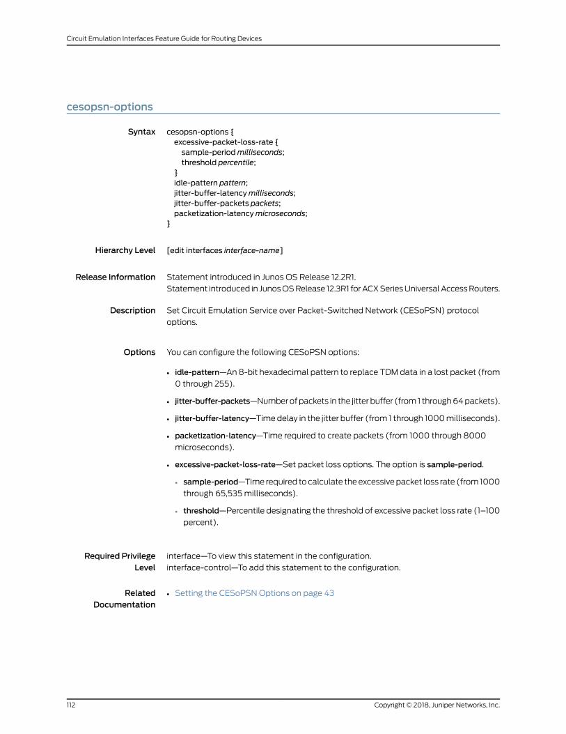
cesopsn-options
Syntax cesopsn-options {excessive-packet-loss-rate {sample-periodmilliseconds;threshold percentile;
}idle-pattern pattern;jitter-buffer-latencymilliseconds;jitter-buffer-packets packets;packetization-latencymicroseconds;
}
Hierarchy Level [edit interfaces interface-name]
Release Information Statement introduced in Junos OS Release 12.2R1.
Statement introduced in JunosOSRelease 12.3R1 forACXSeriesUniversalAccessRouters.
Description Set Circuit Emulation Service over Packet-Switched Network (CESoPSN) protocol
options.
Options You can configure the following CESoPSN options:
• idle-pattern—An8-bit hexadecimal pattern to replace TDMdata in a lost packet (from
0 through 255).
• jitter-buffer-packets—Numberofpackets in the jitter buffer (from1 through64packets).
• jitter-buffer-latency—Timedelay in the jitter buffer (from 1 through 1000milliseconds).
• packetization-latency—Time required to create packets (from 1000 through 8000
microseconds).
• excessive-packet-loss-rate—Set packet loss options. The option is sample-period.
• sample-period—Time required tocalculate theexcessivepacket loss rate (from1000
through 65,535milliseconds).
• threshold—Percentile designating the threshold of excessive packet loss rate (1–100
percent).
Required PrivilegeLevel
interface—To view this statement in the configuration.
interface-control—To add this statement to the configuration.
RelatedDocumentation
• Setting the CESoPSNOptions on page 43
Copyright © 2018, Juniper Networks, Inc.112
Circuit Emulation Interfaces Feature Guide for Routing Devices

event (CFM)
Syntax event {adjacency-loss;interface-status-tlv [lower-layer-down down];port-status-tlv blocked;rdi;
}}
Hierarchy Level [edit protocols oam ethernet connectivity-fault-management action-profile]
Release Information Statement introduced in Junos OS Release 10.1
Description Configure threshold values for connectivity faultmanagement events in an action profile.
Options adjacency-loss—Connectivity is lost.
interface-status-tlv [ lower-layer-down down ]—Values that need to bemonitored ininterface status TLV.
port-status-tlv—Values that need to bemonitored in port status TLV.
rdi—RDI received from someMEP.
Required PrivilegeLevel
interface—To view this statement in the configuration.
interface-control—To add this statement to the configuration.
RelatedDocumentation
• Configuring a CFM Action Profile to Specify CFM Actions for CFM Events
• interface-status-tlv
• port-status-tlv
113Copyright © 2018, Juniper Networks, Inc.
Chapter 8: Configuration Statements
fast-aps-switch
Syntax fast-aps-switch;
Hierarchy Level [edit interfaces interface-name sonet-options aps]
Release Information Statement introduced in Junos OS Release 12.1.
Description (M320 routers with Channelized OC3/STM1 Circuit Emulation PIC with SFP only, EX
Series switches, and MX series routers with Channelized OC3/STM1 Circuit Emulation
PICwithSFPonly using container interfaces)Reduce theAutomaticProtectionSwitching
(APS) switchover time in Layer 2 circuits.
NOTE:
• The fast APS switching feature is supported only within a single chassison aMX series router using a container interface.
• Configuring this statement reduces the APS switchover time only whentheLayer2circuit encapsulation type for the interface receiving traffic froma Layer 2 circuit neighbor is SAToP.
• When the fast-aps-switch statement is configured in revertive APSmode,
youmustconfigureanappropriatevalue for revert timetoachieve reductionin APS switchover time.
• To prevent the logical interfaces in the data path from being shut down,configure appropriate hold-time values on all the interfaces in the datapath that support TDM.
• The fast-aps-switchstatementcannotbeconfiguredwhentheAPSannex-b
option is configured.
• The interfaces that have the fast-aps-switch statement configured cannot
be used in virtual private LAN service (VPLS) environments.
Required PrivilegeLevel
interface—To view this statement in the configuration.
interface-control—To add this statement to the configuration.
RelatedDocumentation
• Reducing APS Switchover Time in Layer 2 Circuits
Copyright © 2018, Juniper Networks, Inc.114
Circuit Emulation Interfaces Feature Guide for Routing Devices
ima-group-options
Syntax ima-group-options {differential-delay number;frame-length (32 |64 |128 |256);frame-synchronization {alpha number;beta number;gamma number;
}minimum-links number;symmetry (symmetrical-config-and-operation |symmetrical-config-asymmetrical-operation);
test-procedure {ima-test-start;ima-test-stop;interface name;pattern number;period number;
}transmit-clock (common |independent);version (1.0 |1.1);
}
Hierarchy Level [edit interfaces (t1-fpc/pic/port:m:n | e1-fpc/pic/port:n | t1|e1-fpc/pic/port)]
Release Information Statement introduced in Junos OS Release 10.0.
Statement introduced in Junos OS Release 12.2 for the ACX Series Universal Access
Routers.
Description Specify IMA group options.
Options differential-delaymsec—Maximum differential delay among links in msec.
Range: 1 through 56
Default: 25
frame-length (32 |64 |128 |256)—IMA frame length in number of cells.
Default: 128
frame-synchronization—IMA group frame synchronization selection.
alpha number—Number of consecutive invalid ICP cells for IFSM.
Range: 1 through 2
Default: 2
beta number—Number of consecutive errored ICP cells for IFSM.
Range: 1 through 2
Default: 2
115Copyright © 2018, Juniper Networks, Inc.
Chapter 8: Configuration Statements

gamma number—Number of consecutive valid ICP cells for IFSM.
Range: 1 through 5
Default: 1
minimum-links number—IMA groupminimum active links.
Range: 1 through 8
Default: 1
symmetry (symmetrical-config-and-operation |
symmetrical-config-asymmetrical-operation)—IMAgroupsymmetrymodeselection.
test-procedure—Specify an IMA link interface test.
ima-test-start—Start IMA group test.
ima-test-stop—Stop IMA group test.
interface name—Interface name of the IMA link to test.
pattern number—IMA test pattern.
Range: 1 through 254
Default: 170
period seconds—Length of IMA pattern test in seconds.
Range: 1 through 4,294,967,294.
Default: 10
transmit-clock (common |independent)—Transmit clock configuration.
Default: common
version (1.0 |1.1)—IMA specification version.
Required PrivilegeLevel
interface—To view this statement in the configuration.
interface-control—To add this statement to the configuration.
RelatedDocumentation
• ATM Support on Circuit Emulation PICs Overview on page 59
• ima-link-options on page 117
• Understanding Inverse Multiplexing for ATM on page 68
Copyright © 2018, Juniper Networks, Inc.116
Circuit Emulation Interfaces Feature Guide for Routing Devices

ima-link-options
Syntax ima-link-options group g
Hierarchy Level [edit interfaces (t1-fpc/pic/port:m:n | e1-fpc/pic/port:n | t1|e1-fpc/pic/port)]
Release Information Statement introduced in Junos OS Release 10.0.
Statement introduced in Junos OS Release 12.2 for the ACX Series Universal Access
Routers.
Description Specify an interface as amember of an IMA group.
Options group g—Implying at-x/y/g.
Required PrivilegeLevel
interface—To view this statement in the configuration.
interface-control—To add this statement to the configuration.
RelatedDocumentation
• ATM Support on Circuit Emulation PICs Overview on page 59
• ima-group-options on page 115
• Inverse Multiplexing for ATM (IMA) Overview
no-vpivci-swapping
Syntax no-vpivci-swapping;
Hierarchy Level [edit interfaces at-fpc/pic/port unit logical-unit-number]
Release Information Statement introduced in Junos OS Release 12.1.
Description Disable the swapping of VPI and VCI values in ATM CCC cell-relay mode on ATMMICs.
TheVPIandVCI valuesarenotmodifiedon ingressor egress. This statement is compatible
with the ATM policing feature.
Required PrivilegeLevel
interface—To view this statement in the configuration.
interface-control—To add this statement to the configuration.
RelatedDocumentation
• Configuring ATM Cell-Relay Promiscuous Mode
117Copyright © 2018, Juniper Networks, Inc.
Chapter 8: Configuration Statements

payload-size
Syntax payload-size bytes ;
Hierarchy Level [edit interfaces interface-name satop-options]
Release Information Statement introduced in Junos OS Release 9.3.
Description Specify the satop-options payload size in integer number of bytes.
Required PrivilegeLevel
interface—To view this statement in the configuration.
interface-control—To add this statement to the configuration.
RelatedDocumentation
• ATM Support on Circuit Emulation PICs Overview on page 59
• satop-options on page 120
psn-vci (ATMCCC Cell-Relay PromiscuousMode VPI/VCI Swapping)
Syntax psn-vci psn-vci-identifier;
Hierarchy Level [edit interfaces at-fpc/pic/port unit logical-unit-number]
Release Information Statement introduced in Junos OS Release 12.1.
Statement introduced in Junos OS Release 12.2 for the ACX Series Universal Access
Routers.
Description (MXSeries routers) Swapboth the VPI andVCI values on both egress and ingress in ATM
CCC cell-relay mode on ATMMICs. This statement is not compatible with the ATM
policing feature.
Options psn-vci-identifier—ATM PSN virtual circuit identifier.
Range: 0 through 255
Required PrivilegeLevel
interface—To view this statement in the configuration.
interface-control—To add this statement to the configuration.
RelatedDocumentation
• Configuring ATM Cell-Relay Promiscuous Mode
Copyright © 2018, Juniper Networks, Inc.118
Circuit Emulation Interfaces Feature Guide for Routing Devices

psn-vpi (ATMCCC Cell-Relay PromiscuousMode VPI/VCI Swapping)
Syntax psn-vpi psn-vpi-identifier;
Hierarchy Level [edit interfaces at-fpc/pic/port unit logical-unit-number]
Release Information Statement introduced in Junos OS Release 12.1.
Statement introduced in Junos OS Release 12.2 for the ACX Series Universal Access
Routers.
Description (MX Series routers) Swap only the VPI values on both egress and ingress in ATM CCC
cell-relay mode on ATMMICs. This statement is not compatible with the ATM policing
feature.
Options psn-vpi-identifier—ATM PSN virtual path identifier.
Range: 0 through 255
Required PrivilegeLevel
interface—To view this statement in the configuration.
interface-control—To add this statement to the configuration.
RelatedDocumentation
• Configuring ATM Cell-Relay Promiscuous Mode
119Copyright © 2018, Juniper Networks, Inc.
Chapter 8: Configuration Statements
satop-options
Syntax satop-options {excessive-packet-loss-rate {apply-groups group-nameapply-groups-except group-namegroups group-namesample-periodmillisecondsthreshold percentile
)idle-pattern patternjitter-buffer-auto-adjustjitter-buffer-latencymillisecondsjitter-buffer-packets packetspayload-size bytes;
}
Hierarchy Level [edit interfaces interface-name]
Release Information Statement introduced in Junos OS Release 9.3.
Statement introduced in Junos OS Release 12.2 for the ACX Series Universal Access
Routers.
Description Set Structure-Agnostic TDM over Packet (SAToP) protocol options.
On ACX Series routers, the following statements are not supported:
apply-groups group-nameapply-groups-except group-namegroups group-namejitter-buffer-auto-adjust
Options excessive-packet-loss-rate options—Set packet loss options.
• apply-groups group-name—Groups fromwhich to inherit configuration data.
• apply-groups-except group-name—Don't inherit configuration data from these groups.
• groups group-name—Specify groups.
• sample-periodmilliseconds—Number ofmilliseconds overwhich excessive packet loss
rate is calculated.
• thresholdpercentile—Percentile designating the threshold of excessive packet loss rate
(from 1 to 100).
idle-pattern pattern—An 8–bit hexadecimal pattern to replace TDM data in a lost packet
(from 0 to 255).
jitter-buffer-auto-adjust—Automatically adjust the jitter buffer.
Copyright © 2018, Juniper Networks, Inc.120
Circuit Emulation Interfaces Feature Guide for Routing Devices

NOTE: This option is not applicable onMX Series routers.
jitter-buffer-latencymilliseconds—Number ofmilliseconds delay in jitter buffer (from 1 to
1000milliseconds).
jitter-buffer-packets packets—Number of packets in jitter buffer (from 1 to 64).
payload-size bytes—Payload size in integer number of bytes.
Required PrivilegeLevel
interface—To view this statement in the configuration.
interface-control—To add this statement to the configuration.
RelatedDocumentation
• ConfiguringSAToPon4-PortChannelizedOC3/STM1Circuit EmulationMICsonpage 19
• Configuring SAToP Emulation on T1/E1 Interfaces on 12-Port Channelized T1/E1 Circuit
Emulation PICs on page 26
• ATM Support on Circuit Emulation PICs Overview on page 59
121Copyright © 2018, Juniper Networks, Inc.
Chapter 8: Configuration Statements

Copyright © 2018, Juniper Networks, Inc.122
Circuit Emulation Interfaces Feature Guide for Routing Devices

CHAPTER 9
Operational Commands
• show interfaces (ATM)
• show interfaces (T1, E1, or DS)
• show interfaces extensive
123Copyright © 2018, Juniper Networks, Inc.
show interfaces (ATM)
Syntax show interfaces at-fpc/pic/port<brief | detail | extensive | terse><descriptions><media><snmp-index snmp-index><statistics>
Release Information Command introduced before Junos OS Release 7.4.
Description (M Series and T Series routers only) Display status information about the specified ATM
interface.
Options at-fpc/pic/port—Display standard information about the specified ATM interface.
brief | detail | extensive | terse—(Optional) Display the specified level of output.
descriptions—(Optional) Display interface description strings.
media—(Optional) Display media-specific information about network interfaces.
snmp-index snmp-index—(Optional) Display the SNMP index of the interface.
statistics—(Optional) Display static interface statistics.
Required PrivilegeLevel
view
List of Sample Output show interfaces (ATM, IMAGroup) on page 139show interfaces extensive (ATM IMAGroup) on page 140show interfaces (ATM1, SONETMode) on page 141show interfaces brief (ATM1, SONETMode) on page 142show interfaces detail (ATM1, SONETMode) on page 142show interfaces extensive (ATM1, SONETMode) on page 143show interfaces (ATM2, SDHMode) on page 145show interfaces brief (ATM2, SDHMode) on page 146show interfaces detail (ATM2, SDHMode) on page 147show interfaces extensive (ATM2, SDHMode) on page 148show interfaces (ATM2, SONETMode) on page 151show interfaces brief (ATM2, SONETMode) on page 152show interfaces detail (ATM2, SONETMode) on page 153show interfaces extensive (ATM2, SONETMode) on page 155
Output Fields Table 13 on page 125 lists the output fields for the show interfaces (ATM) command.
Output fields are listed in the approximate order in which they appear.
Copyright © 2018, Juniper Networks, Inc.124
Circuit Emulation Interfaces Feature Guide for Routing Devices
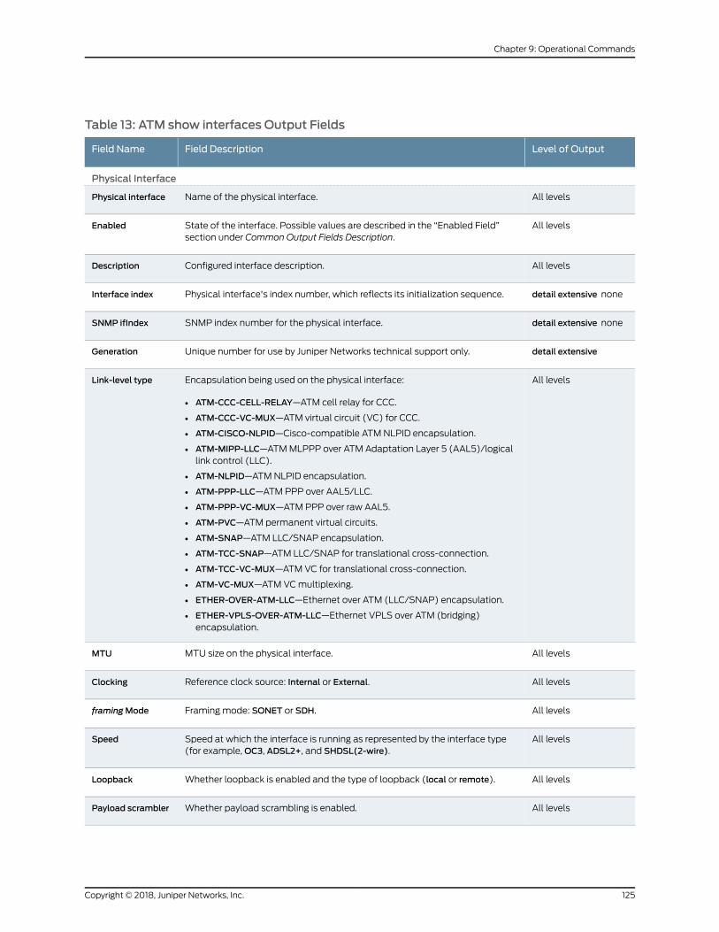
Table 13: ATM show interfaces Output Fields
Level of OutputField DescriptionField Name
Physical Interface
All levelsName of the physical interface.Physical interface
All levelsState of the interface. Possible values are described in the “Enabled Field”section under Common Output Fields Description.
Enabled
All levelsConfigured interface description.Description
detail extensive nonePhysical interface's index number, which reflects its initialization sequence.Interface index
detail extensive noneSNMP index number for the physical interface.SNMP ifIndex
detail extensiveUnique number for use by Juniper Networks technical support only.Generation
All levelsEncapsulation being used on the physical interface:
• ATM-CCC-CELL-RELAY—ATM cell relay for CCC.
• ATM-CCC-VC-MUX—ATM virtual circuit (VC) for CCC.
• ATM-CISCO-NLPID—Cisco-compatible ATM NLPID encapsulation.
• ATM-MIPP-LLC—ATMMLPPP over ATM Adaptation Layer 5 (AAL5)/logicallink control (LLC).
• ATM-NLPID—ATMNLPID encapsulation.
• ATM-PPP-LLC—ATM PPP over AAL5/LLC.
• ATM-PPP-VC-MUX—ATM PPP over raw AAL5.
• ATM-PVC—ATM permanent virtual circuits.
• ATM-SNAP—ATM LLC/SNAP encapsulation.
• ATM-TCC-SNAP—ATM LLC/SNAP for translational cross-connection.
• ATM-TCC-VC-MUX—ATM VC for translational cross-connection.
• ATM-VC-MUX—ATM VCmultiplexing.
• ETHER-OVER-ATM-LLC—Ethernet over ATM (LLC/SNAP) encapsulation.
• ETHER-VPLS-OVER-ATM-LLC—Ethernet VPLS over ATM (bridging)encapsulation.
Link-level type
All levelsMTU size on the physical interface.MTU
All levelsReference clock source: Internal or External.Clocking
All levelsFramingmode: SONET or SDH.framingMode
All levelsSpeed at which the interface is running as represented by the interface type(for example,OC3, ADSL2+, and SHDSL(2-wire).
Speed
All levelsWhether loopback is enabled and the type of loopback (local or remote).Loopback
All levelsWhether payload scrambling is enabled.Payload scrambler
125Copyright © 2018, Juniper Networks, Inc.
Chapter 9: Operational Commands

Table 13: ATM show interfaces Output Fields (continued)
Level of OutputField DescriptionField Name
All levelsInformation about the physical device. Possible values are described in the“Device Flags” section under Common Output Fields Description.
Device flags
All levelsInformation about the link. Possible values are described in the “Link Flags”section under Common Output Fields Description.
Link flags
detail extensive noneNumber of CoS queues configured.CoS queues
detail extensiveCurrent interface hold-time up and hold-time down, in milliseconds.Hold-times
detail extensive noneEthernet MAC address for this interface for Ethernet over ATM encapsulation.Current address
detail extensive noneDate, time, and how long ago the interface went from down to up. The formatisLast flapped:year-month-dayhour:minute:secondtimezone (hour:minute:secondago). For example, Last flapped: 2002-04-26 10:52:40 PDT (04:33:20 ago).
Last flapped
None specifiedInput rate in bits per second (bps) and packets per second (pps).Input Rate
None specifiedOutput rate in bps and pps.Output Rate
detail extensiveTime when the statistics for the interface were last set to zero.Statistics lastcleared
detail extensiveStatistics for traffic on the interface.
• Input bytes—Number of bytes received on the interface
• Output bytes—Number of bytes transmitted on the interface.
• Input packets—Number of packets received on the interface
• Output packets—Number of packets transmitted on the interface.
Traffic statistics
Copyright © 2018, Juniper Networks, Inc.126
Circuit Emulation Interfaces Feature Guide for Routing Devices

Table 13: ATM show interfaces Output Fields (continued)
Level of OutputField DescriptionField Name
extensiveInput errors on the interface whose definitions are as follows:
• Errors—Sumof the incoming frame aborts and frame check sequence (FCS)errors.
• Drops—Number of packets dropped by the input queue of the I/O ManagerASIC. If the interface is saturated, this number increments once for everypacket that is dropped by the ASIC's random early detection (RED)mechanism.
• Invalid VCs—Number of cells that arrived for a nonexistent VC.
• Framing errors—Sum of AAL5 packets that have FCS errors, reassemblytimeout errors, and length errors.
• Policed discards—Number of frames that the incoming packet match codediscarded because they were not recognized or not of interest. Usually, thisfield reports protocols that the Junos OS does not handle.
• L3 incompletes—Number of incoming packets discarded because they failedLayer 3 (usually IPv4) sanity checks of the header. For example, a framewithless than 20 bytes of available IP header is discarded.
• L2 channel errors—Number of times the software did not find a valid logicalinterface for an incoming frame.
• L2mismatch timeouts—Number of malformed or short packets that causedthe incoming packet handler to discard the frame as unreadable.
• Resource errors—Sum of transmit drops.
Input errors
extensiveOutput errors on the interface. The following paragraphs explain the counterswhosemeaning might not be obvious:
• Carrier transitions—Number of times the interface has gone from down to up.This number does not normally increment quickly, increasing only when thecable is unplugged, the far-end system is powered down and up, or anotherproblem occurs. If the number of carrier transitions increments quickly,increasing only when the cable is unplugged, the far-end system is powereddownandthenup,oranotherproblemoccurs. If it incrementsquickly (perhapsonce every 10 seconds), the cable, the far-end system, or the PIC or PIM ismalfunctioning.
• Errors—Sum of the outgoing frame aborts and FCS errors.
• Drops—Number of packets dropped by the output queue of the I/OManagerASIC. If the interface is saturated, this number increments once for everypacket that is dropped by the ASIC's REDmechanism.
• Aged packets—Number of packets that remained so long in shared packetSDRAM that the system automatically purged them. The value in this fieldshould never increment. If it does, it is most likely a software bug or possiblymalfunctioning hardware.
• MTU errors—Number of packets larger than the MTU threshold.
• Resource errors—Sum of transmit drops.
Output errors
detail extensiveTotal number of egress queues supported on the specified interface.Egress queues
127Copyright © 2018, Juniper Networks, Inc.
Chapter 9: Operational Commands

Table 13: ATM show interfaces Output Fields (continued)
Level of OutputField DescriptionField Name
detail extensiveCoS queue number and its associated user-configured forwarding class name.
• Queued packets—Number of queued packets.
• Transmitted packets—Number of transmitted packets.
• Droppedpackets—Numberofpacketsdroppedby theASIC'sREDmechanism.
NOTE: Physical interface queue counters of ATM2 PICs displayed by the showinterfaces at-fpc/pic/port detail command show the packet forwarding streamstatistics associated with the ATM2 ports. Since multiple ports of the ATM2PICs(except for theATM2dual-portOC12)shareonepacket forwardingstream,the physical interface queue counters reflect the aggregate of ATM2 portstatistics.
Queue counters
detail extensive noneSONETmedia-specific defects thatprevent the interface frompassingpackets.When a defect persists for a certain period, it is promoted to an alarm. Basedon the router configuration, an alarm can ring the red or yellow alarm bell onthe router or light the red or yellow alarm LED on the craft interface. See thesefields for possible alarms and defects: SONETPHY, SONET section, SONET line,and SONET path.
SONET alarms
SONET defects
extensiveCounts of specific SONET errors with detailed information.
• Seconds—Number of seconds the defect has been active.
• Count—Number of times that the defect has gone from inactive to active.
• State—State of the error. State other thanOK indicates a problem.
Subfields are:
• PLL Lock—Phase-locked loop
• PHY Light—Loss of optical signal
SONET PHY
extensiveCounts of specific SONET errors with detailed information.
• Seconds—Number of seconds the defect has been active.
• Count—Number of times that the defect has gone from inactive to active.
• State—State of the error. State other thanOK indicates a problem.
Subfields are:
• BIP-B1—Bit interleaved parity for SONET section overhead
• SEF—Severely errored framing
• LOL—Loss of light
• LOF—Loss of frame
• ES-S—Errored seconds (section)
• SES-S—Severely errored seconds (section)
• SEFS-S—Severely errored framing seconds (section)
SONET section
Copyright © 2018, Juniper Networks, Inc.128
Circuit Emulation Interfaces Feature Guide for Routing Devices
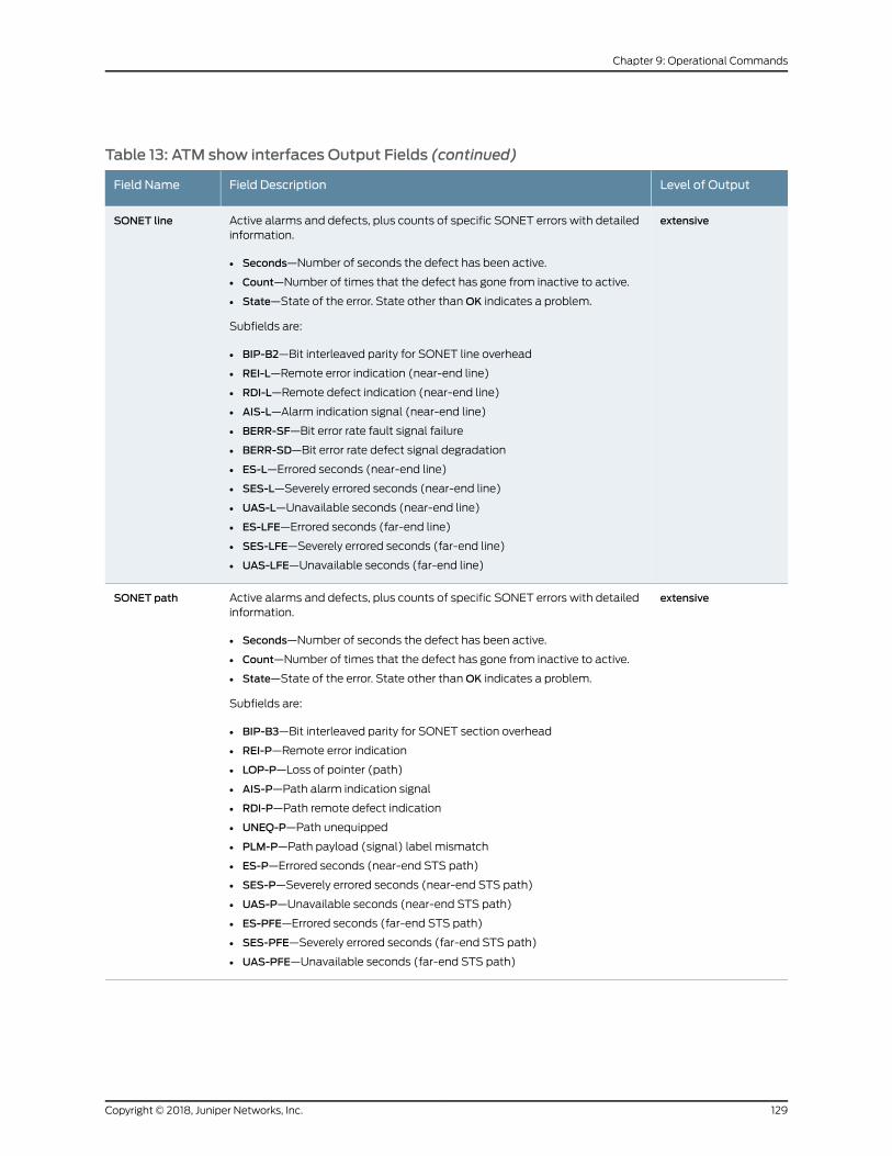
Table 13: ATM show interfaces Output Fields (continued)
Level of OutputField DescriptionField Name
extensiveActive alarms and defects, plus counts of specific SONET errors with detailedinformation.
• Seconds—Number of seconds the defect has been active.
• Count—Number of times that the defect has gone from inactive to active.
• State—State of the error. State other thanOK indicates a problem.
Subfields are:
• BIP-B2—Bit interleaved parity for SONET line overhead
• REI-L—Remote error indication (near-end line)
• RDI-L—Remote defect indication (near-end line)
• AIS-L—Alarm indication signal (near-end line)
• BERR-SF—Bit error rate fault signal failure
• BERR-SD—Bit error rate defect signal degradation
• ES-L—Errored seconds (near-end line)
• SES-L—Severely errored seconds (near-end line)
• UAS-L—Unavailable seconds (near-end line)
• ES-LFE—Errored seconds (far-end line)
• SES-LFE—Severely errored seconds (far-end line)
• UAS-LFE—Unavailable seconds (far-end line)
SONET line
extensiveActive alarms and defects, plus counts of specific SONET errors with detailedinformation.
• Seconds—Number of seconds the defect has been active.
• Count—Number of times that the defect has gone from inactive to active.
• State—State of the error. State other thanOK indicates a problem.
Subfields are:
• BIP-B3—Bit interleaved parity for SONET section overhead
• REI-P—Remote error indication
• LOP-P—Loss of pointer (path)
• AIS-P—Path alarm indication signal
• RDI-P—Path remote defect indication
• UNEQ-P—Path unequipped
• PLM-P—Path payload (signal) label mismatch
• ES-P—Errored seconds (near-end STS path)
• SES-P—Severely errored seconds (near-end STS path)
• UAS-P—Unavailable seconds (near-end STS path)
• ES-PFE—Errored seconds (far-end STS path)
• SES-PFE—Severely errored seconds (far-end STS path)
• UAS-PFE—Unavailable seconds (far-end STS path)
SONET path
129Copyright © 2018, Juniper Networks, Inc.
Chapter 9: Operational Commands
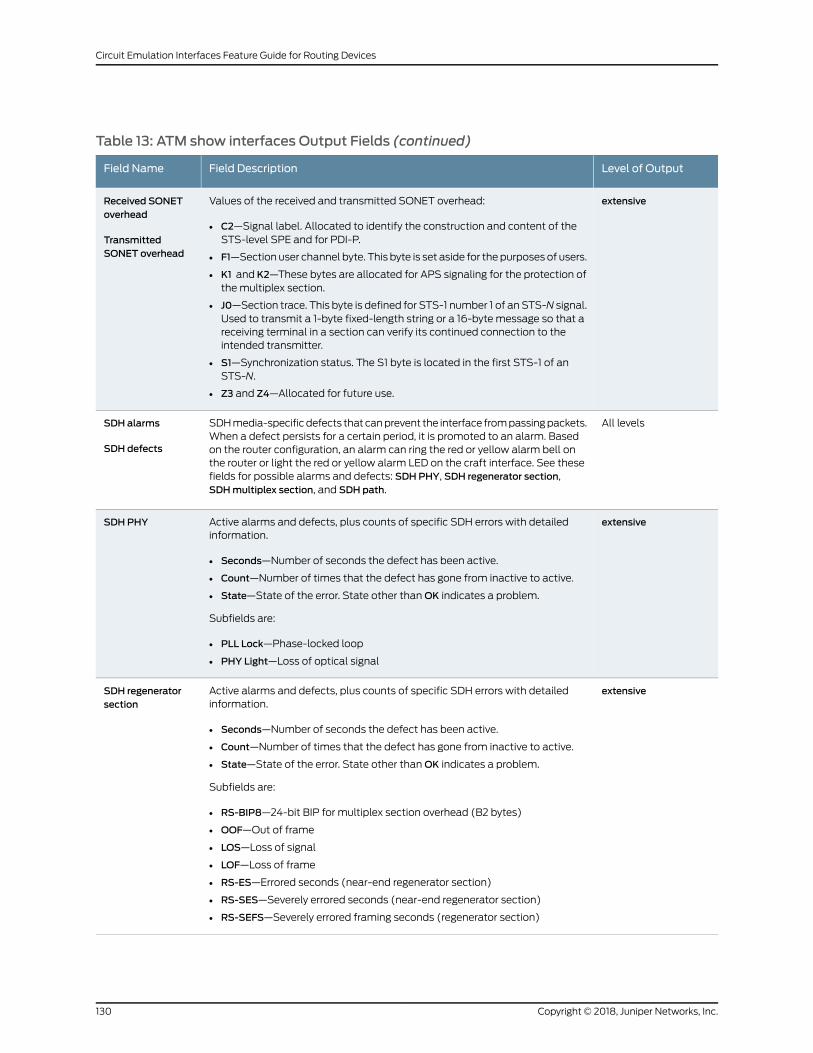
Table 13: ATM show interfaces Output Fields (continued)
Level of OutputField DescriptionField Name
extensiveValues of the received and transmitted SONET overhead:
• C2—Signal label. Allocated to identify the construction and content of theSTS-level SPE and for PDI-P.
• F1—Section user channel byte. This byte is set aside for the purposes of users.
• K1 and K2—These bytes are allocated for APS signaling for the protection ofthe multiplex section.
• J0—Section trace. This byte is defined for STS-1 number 1 of an STS-N signal.Used to transmit a 1-byte fixed-length string or a 16-byte message so that areceiving terminal in a section can verify its continued connection to theintended transmitter.
• S1—Synchronization status. The S1 byte is located in the first STS-1 of anSTS-N.
• Z3 and Z4—Allocated for future use.
Received SONEToverhead
TransmittedSONET overhead
All levelsSDHmedia-specificdefects that canprevent the interface frompassingpackets.When a defect persists for a certain period, it is promoted to an alarm. Basedon the router configuration, an alarm can ring the red or yellow alarm bell onthe router or light the red or yellow alarm LED on the craft interface. See thesefields for possible alarms and defects: SDHPHY, SDH regenerator section,SDHmultiplex section, and SDH path.
SDH alarms
SDH defects
extensiveActive alarms and defects, plus counts of specific SDH errors with detailedinformation.
• Seconds—Number of seconds the defect has been active.
• Count—Number of times that the defect has gone from inactive to active.
• State—State of the error. State other thanOK indicates a problem.
Subfields are:
• PLL Lock—Phase-locked loop
• PHY Light—Loss of optical signal
SDHPHY
extensiveActive alarms and defects, plus counts of specific SDH errors with detailedinformation.
• Seconds—Number of seconds the defect has been active.
• Count—Number of times that the defect has gone from inactive to active.
• State—State of the error. State other thanOK indicates a problem.
Subfields are:
• RS-BIP8—24-bit BIP for multiplex section overhead (B2 bytes)
• OOF—Out of frame
• LOS—Loss of signal
• LOF—Loss of frame
• RS-ES—Errored seconds (near-end regenerator section)
• RS-SES—Severely errored seconds (near-end regenerator section)
• RS-SEFS—Severely errored framing seconds (regenerator section)
SDH regeneratorsection
Copyright © 2018, Juniper Networks, Inc.130
Circuit Emulation Interfaces Feature Guide for Routing Devices
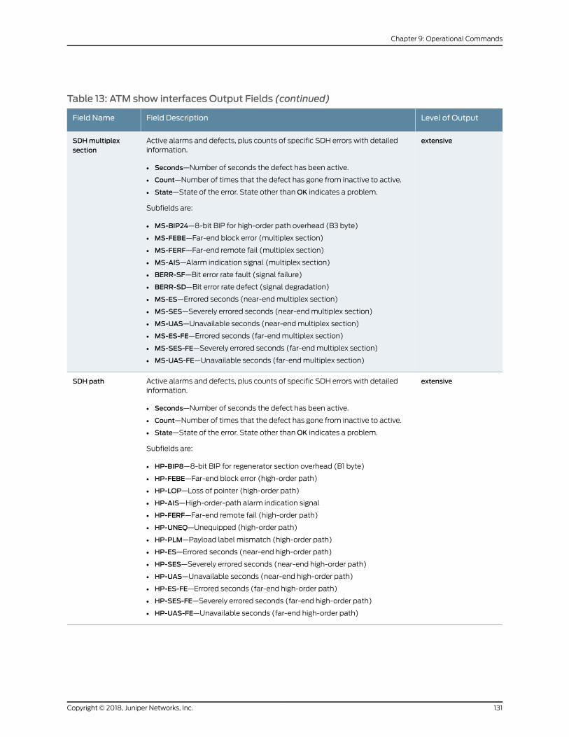
Table 13: ATM show interfaces Output Fields (continued)
Level of OutputField DescriptionField Name
extensiveActive alarms and defects, plus counts of specific SDH errors with detailedinformation.
• Seconds—Number of seconds the defect has been active.
• Count—Number of times that the defect has gone from inactive to active.
• State—State of the error. State other thanOK indicates a problem.
Subfields are:
• MS-BIP24—8-bit BIP for high-order path overhead (B3 byte)
• MS-FEBE—Far-end block error (multiplex section)
• MS-FERF—Far-end remote fail (multiplex section)
• MS-AIS—Alarm indication signal (multiplex section)
• BERR-SF—Bit error rate fault (signal failure)
• BERR-SD—Bit error rate defect (signal degradation)
• MS-ES—Errored seconds (near-endmultiplex section)
• MS-SES—Severely errored seconds (near-endmultiplex section)
• MS-UAS—Unavailable seconds (near-endmultiplex section)
• MS-ES-FE—Errored seconds (far-endmultiplex section)
• MS-SES-FE—Severely errored seconds (far-endmultiplex section)
• MS-UAS-FE—Unavailable seconds (far-endmultiplex section)
SDHmultiplexsection
extensiveActive alarms and defects, plus counts of specific SDH errors with detailedinformation.
• Seconds—Number of seconds the defect has been active.
• Count—Number of times that the defect has gone from inactive to active.
• State—State of the error. State other thanOK indicates a problem.
Subfields are:
• HP-BIP8—8-bit BIP for regenerator section overhead (B1 byte)
• HP-FEBE—Far-end block error (high-order path)
• HP-LOP—Loss of pointer (high-order path)
• HP-AIS—High-order-path alarm indication signal
• HP-FERF—Far-end remote fail (high-order path)
• HP-UNEQ—Unequipped (high-order path)
• HP-PLM—Payload label mismatch (high-order path)
• HP-ES—Errored seconds (near-end high-order path)
• HP-SES—Severely errored seconds (near-end high-order path)
• HP-UAS—Unavailable seconds (near-end high-order path)
• HP-ES-FE—Errored seconds (far-end high-order path)
• HP-SES-FE—Severely errored seconds (far-end high-order path)
• HP-UAS-FE—Unavailable seconds (far-end high-order path)
SDH path
131Copyright © 2018, Juniper Networks, Inc.
Chapter 9: Operational Commands
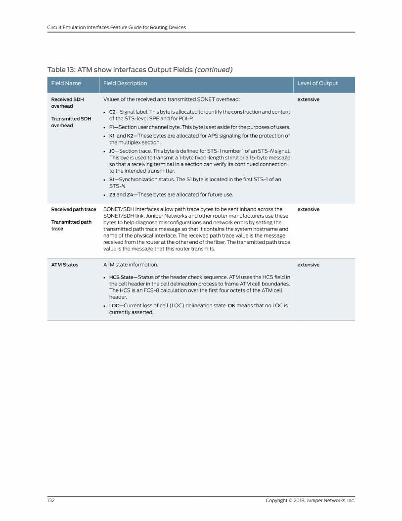
Table 13: ATM show interfaces Output Fields (continued)
Level of OutputField DescriptionField Name
extensiveValues of the received and transmitted SONET overhead:
• C2—Signal label. Thisbyte isallocated to identify theconstructionandcontentof the STS-level SPE and for PDI-P.
• F1—Section user channel byte. This byte is set aside for the purposes of users.
• K1 and K2—These bytes are allocated for APS signaling for the protection ofthe multiplex section.
• J0—Section trace. This byte is defined for STS-1 number 1 of an STS-N signal.This bye is used to transmit a 1-byte fixed-length string or a 16-bytemessageso that a receiving terminal in a section can verify its continued connectionto the intended transmitter.
• S1—Synchronization status. The S1 byte is located in the first STS-1 of anSTS-N.
• Z3 and Z4—These bytes are allocated for future use.
Received SDHoverhead
Transmitted SDHoverhead
extensiveSONET/SDH interfaces allow path trace bytes to be sent inband across theSONET/SDH link. Juniper Networks and other router manufacturers use thesebytes to help diagnosemisconfigurations and network errors by setting thetransmitted path trace message so that it contains the system hostname andname of the physical interface. The received path trace value is the messagereceived fromthe router at theother endof the fiber. The transmittedpath tracevalue is the message that this router transmits.
Receivedpath trace
Transmitted pathtrace
extensiveATM state information:
• HCS State—Status of the header check sequence. ATM uses the HCS field inthe cell header in the cell delineation process to frame ATM cell boundaries.The HCS is an FCS-8 calculation over the first four octets of the ATM cellheader.
• LOC—Current loss of cell (LOC) delineation state.OKmeans that no LOC iscurrently asserted.
ATMStatus
Copyright © 2018, Juniper Networks, Inc.132
Circuit Emulation Interfaces Feature Guide for Routing Devices

Table 13: ATM show interfaces Output Fields (continued)
Level of OutputField DescriptionField Name
extensiveATM statistics for the interface:
• Uncorrectable HCS errors—Number of cells dropped because the celldelineation failed. These errors most likely indicate that a SONET/SDH layerproblem has occurred.
• CorrectableHCSerrors—Number of correctableHCSerrors that occurred. Thecell delineation process can recover from these errors and locate the ATMcell boundary, although the framing process is not quite stable. The ATM cellis not dropped. This counter increases when the cell delineation processchanges its state from present to sync (for example, when a cable is pluggedinto the interface).
The following error statistics are from the framer:
• Tx cell FIFO overruns—Number of overruns in the transmit FIFO.
• Rx cell FIFO overruns—Number of overruns in the receive FIFO.
• Rx cell FIFO underruns—Number of underruns in the receive FIFO.
• Inputcell count—NumberofATMcells receivedby the interface (not includingidle cells).
• Outputcellcount—NumberofATMcells transmittedby the interface(includingidle cells).
• Output idle cell count—Number of idle cells sent by the port. When ATM hasnothing to send, it sends idle cells to fill the time slot.
• Output VC queue drops—Number of packets dropped by a port on the PIC.Packets are dropped because of queue limits on the VCs.
The following error statistics are from the SAR:
• Input no buffers—Number of AAL5 packets dropped because no channelblocks or buffers were available to handle them.
• Input length errors—Number of AAL5 packets dropped because their lengthwas incorrect. Usually, these errors occur because a cell has been corruptedor lost, or because the length field was corrupted. They can also mean theAAL5 length field was zero.
• Input timeouts—Number of AAL5 packets dropped because of a reassemblytimeout.
• Input invalid VCs—Number of AAL5 packets dropped because the headerwas unrecognized (because the VC was not correct or not configured).
• Input bad CRCs—Number of AAL5 packets dropped because of frame checksequence errors.
• InputOAMcellnobuffers—Numberof receivedOAMcellsor rawcellsdroppedbecause no buffers were available to handle them.
• L2 circuit out-of-sequence packets—(Layer 2 AAL5mode) Number of AAL5packets that are out of sequential order.
• Denied packets count—The number of packets dropped due to VLAN prioritydeny packets or due to an error forwarding configuration that might cause anegative frame length, that is, the stripping size is larger than the packet size.
ATMStatistics
extensiveInformation about the configuration of the Packet Forwarding Engine:
• Destination slot—FPC slot number.
Packet ForwardingEngineconfiguration
133Copyright © 2018, Juniper Networks, Inc.
Chapter 9: Operational Commands

Table 13: ATM show interfaces Output Fields (continued)
Level of OutputField DescriptionField Name
extensiveInformation about the CoS queue for the physical interface.
• CoS transmit queue—Queue number and its associated user-configuredforwarding class name.
• Bandwidth%—Percentage of bandwidth allocated to the queue.
• Bandwidth bps—Bandwidth allocated to the queue (in bps).
• Buffer%—Percentage of buffer space allocated to the queue.
• Bufferusec—Amountofbuffer spaceallocated to thequeue, inmicroseconds.This value is nonzero only if the buffer size is configured in terms of time.
• Priority—Queue priority: low or high.
• Limit—Displayed if rate limiting is configured for the queue. Possible valuesare none and exact. If exact is configured, the queue transmits only up to theconfigured bandwidth, even if excess bandwidth is available. If none isconfigured, the queue transmits beyond the configured bandwidth ifbandwidth is available.
CoS information
Copyright © 2018, Juniper Networks, Inc.134
Circuit Emulation Interfaces Feature Guide for Routing Devices
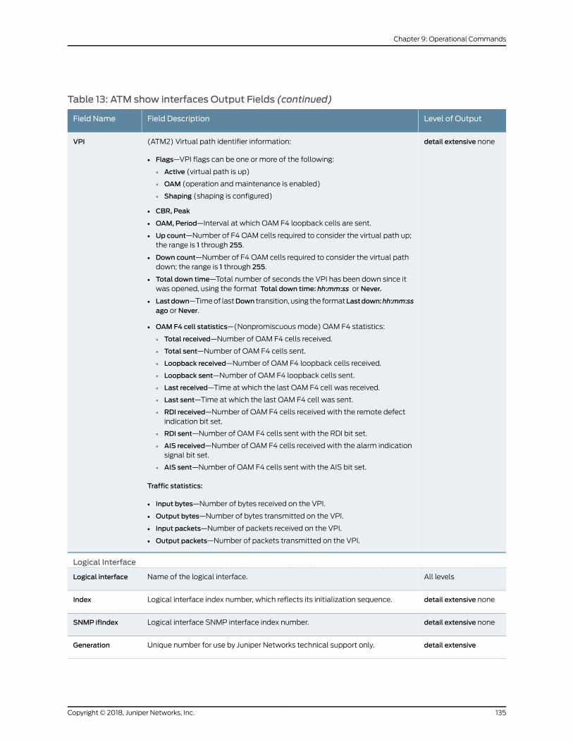
Table 13: ATM show interfaces Output Fields (continued)
Level of OutputField DescriptionField Name
detail extensive none(ATM2) Virtual path identifier information:
• Flags—VPI flags can be one or more of the following:
• Active (virtual path is up)
• OAM (operation andmaintenance is enabled)
• Shaping (shaping is configured)
• CBR, Peak
• OAM, Period—Interval at which OAM F4 loopback cells are sent.
• Up count—Number of F4 OAM cells required to consider the virtual path up;the range is 1 through 255.
• Down count—Number of F4 OAM cells required to consider the virtual pathdown; the range is 1 through 255.
• Total down time—Total number of seconds the VPI has been down since itwas opened, using the format Total down time: hh:mm:ss or Never.
• Lastdown—Timeof lastDown transition, using the formatLastdown:hh:mm:ssago or Never.
• OAM F4 cell statistics—(Nonpromiscuous mode) OAM F4 statistics:
• Total received—Number of OAM F4 cells received.
• Total sent—Number of OAM F4 cells sent.
• Loopback received—Number of OAM F4 loopback cells received.
• Loopback sent—Number of OAM F4 loopback cells sent.
• Last received—Time at which the last OAM F4 cell was received.
• Last sent—Time at which the last OAM F4 cell was sent.
• RDI received—Number of OAM F4 cells received with the remote defectindication bit set.
• RDI sent—Number of OAM F4 cells sent with the RDI bit set.
• AIS received—Number of OAM F4 cells received with the alarm indicationsignal bit set.
• AIS sent—Number of OAM F4 cells sent with the AIS bit set.
Traffic statistics:
• Input bytes—Number of bytes received on the VPI.
• Output bytes—Number of bytes transmitted on the VPI.
• Input packets—Number of packets received on the VPI.
• Output packets—Number of packets transmitted on the VPI.
VPI
Logical Interface
All levelsName of the logical interface.Logical interface
detail extensive noneLogical interface index number, which reflects its initialization sequence.Index
detail extensive noneLogical interface SNMP interface index number.SNMP ifIndex
detail extensiveUnique number for use by Juniper Networks technical support only.Generation
135Copyright © 2018, Juniper Networks, Inc.
Chapter 9: Operational Commands
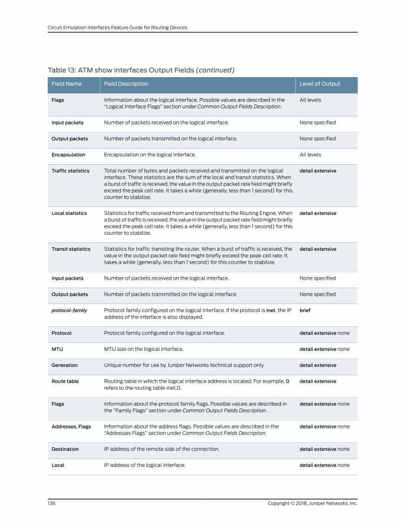
Table 13: ATM show interfaces Output Fields (continued)
Level of OutputField DescriptionField Name
All levelsInformation about the logical interface. Possible values are described in the“Logical Interface Flags” section under Common Output Fields Description.
Flags
None specifiedNumber of packets received on the logical interface.Input packets
None specifiedNumber of packets transmitted on the logical interface.Output packets
All levelsEncapsulation on the logical interface.Encapsulation
detail extensiveTotal number of bytes and packets received and transmitted on the logicalinterface. These statistics are the sum of the local and transit statistics. Whenaburst of traffic is received, the value in theoutputpacket rate fieldmightbrieflyexceed the peak cell rate. It takes a while (generally, less than 1 second) for thiscounter to stabilize.
Traffic statistics
detail extensiveStatistics for traffic received fromand transmitted to the Routing Engine.Whenaburst of traffic is received, the value in theoutputpacket rate fieldmightbrieflyexceed the peak cell rate. It takes a while (generally, less than 1 second) for thiscounter to stabilize.
Local statistics
detail extensiveStatistics for traffic transiting the router. When a burst of traffic is received, thevalue in the output packet rate field might briefly exceed the peak cell rate. Ittakes a while (generally, less than 1 second) for this counter to stabilize.
Transit statistics
None specifiedNumber of packets received on the logical interface.Input packets
None specifiedNumber of packets transmitted on the logical interface.Output packets
briefProtocol family configured on the logical interface. If the protocol is inet, the IPaddress of the interface is also displayed.
protocol-family
detail extensive noneProtocol family configured on the logical interface.Protocol
detail extensive noneMTU size on the logical interface.MTU
detail extensiveUnique number for use by Juniper Networks technical support only.Generation
detail extensiveRouting table in which the logical interface address is located. For example, 0refers to the routing table inet.0.
Route table
detail extensive noneInformation about the protocol family flags. Possible values are described inthe “Family Flags” section under Common Output Fields Description.
Flags
detail extensive noneInformation about the address flags. Possible values are described in the“Addresses Flags” section under Common Output Fields Description.
Addresses, Flags
detail extensive noneIP address of the remote side of the connection.Destination
detail extensive noneIP address of the logical interface.Local
Copyright © 2018, Juniper Networks, Inc.136
Circuit Emulation Interfaces Feature Guide for Routing Devices
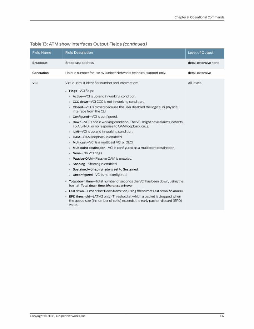
Table 13: ATM show interfaces Output Fields (continued)
Level of OutputField DescriptionField Name
detail extensive noneBroadcast address.Broadcast
detail extensiveUnique number for use by Juniper Networks technical support only.Generation
All levelsVirtual circuit identifier number and information:
• Flags—VCI flags:
• Active—VCI is up and in working condition.
• CCC down—VCI CCC is not in working condition.
• Closed—VCI is closed because the user disabled the logical or physicalinterface from the CLI.
• Configured—VCI is configured.
• Down—VCI is not inworking condition. TheVCImight have alarms, defects,F5 AIS/RDI, or no response to OAM loopback cells.
• ILMI—VCI is up and in working condition.
• OAM—OAM loopback is enabled.
• Multicast—VCI is a multicast VCI or DLCI.
• Multipoint destination—VCI is configured as amultipoint destination.
• None—No VCI flags.
• Passive-OAM—Passive OAM is enabled.
• Shaping—Shaping is enabled.
• Sustained—Shaping rate is set to Sustained.
• Unconfigured—VCI is not configured.
• Total down time—Total number of seconds the VCI has been down, using theformat Total down time: hh:mm:ss orNever.
• Lastdown—Timeof lastDown transition, using the formatLastdown:hh:mm:ss.
• EPD threshold—(ATM2 only) Threshold at which a packet is dropped whenthe queue size (in number of cells) exceeds the early packet-discard (EPD)value.
VCI
137Copyright © 2018, Juniper Networks, Inc.
Chapter 9: Operational Commands
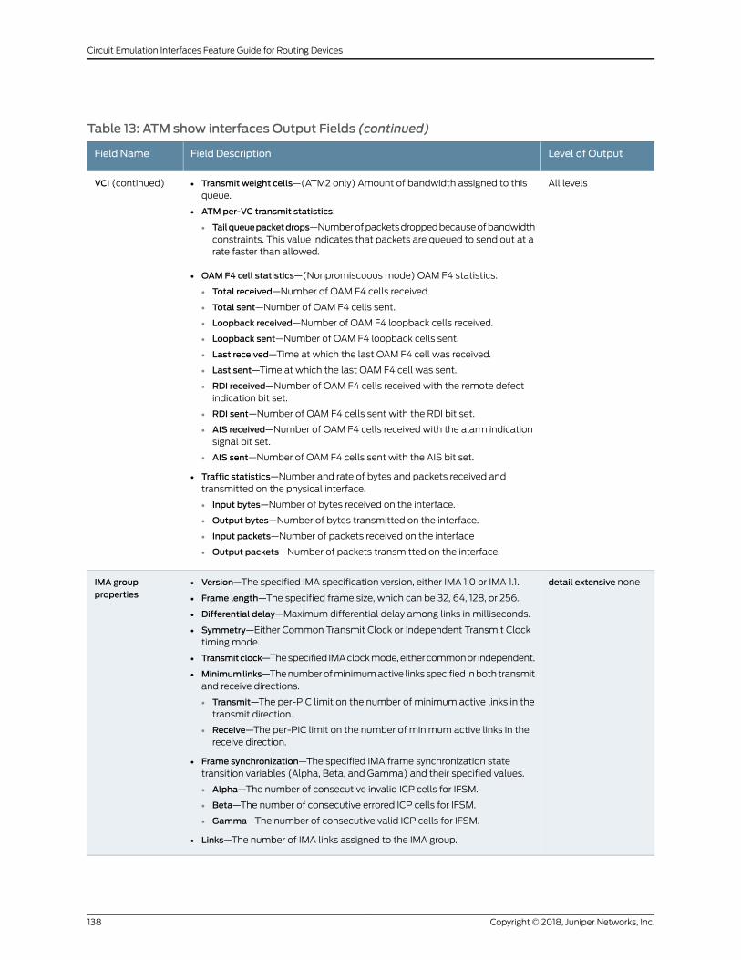
Table 13: ATM show interfaces Output Fields (continued)
Level of OutputField DescriptionField Name
All levels• Transmit weight cells—(ATM2 only) Amount of bandwidth assigned to thisqueue.
• ATMper-VC transmit statistics:
• Tailqueuepacketdrops—Numberofpacketsdroppedbecauseofbandwidthconstraints. This value indicates that packets are queued to send out at arate faster than allowed.
• OAM F4 cell statistics—(Nonpromiscuous mode) OAM F4 statistics:
• Total received—Number of OAM F4 cells received.
• Total sent—Number of OAM F4 cells sent.
• Loopback received—Number of OAM F4 loopback cells received.
• Loopback sent—Number of OAM F4 loopback cells sent.
• Last received—Time at which the last OAM F4 cell was received.
• Last sent—Time at which the last OAM F4 cell was sent.
• RDI received—Number of OAM F4 cells received with the remote defectindication bit set.
• RDI sent—Number of OAM F4 cells sent with the RDI bit set.
• AIS received—Number of OAM F4 cells received with the alarm indicationsignal bit set.
• AIS sent—Number of OAM F4 cells sent with the AIS bit set.
• Traffic statistics—Number and rate of bytes and packets received andtransmitted on the physical interface.
• Input bytes—Number of bytes received on the interface.
• Output bytes—Number of bytes transmitted on the interface.
• Input packets—Number of packets received on the interface
• Output packets—Number of packets transmitted on the interface.
VCI (continued)
detail extensive none• Version—The specified IMA specification version, either IMA 1.0 or IMA 1.1.
• Frame length—The specified frame size, which can be 32, 64, 128, or 256.
• Differential delay—Maximum differential delay among links in milliseconds.
• Symmetry—Either Common Transmit Clock or Independent Transmit Clocktiming mode.
• Transmitclock—Thespecified IMAclockmode,eithercommonor independent.
• Minimumlinks—Thenumberofminimumactive linksspecified inboth transmitand receive directions.
• Transmit—The per-PIC limit on the number of minimum active links in thetransmit direction.
• Receive—The per-PIC limit on the number of minimum active links in thereceive direction.
• Frame synchronization—The specified IMA frame synchronization statetransition variables (Alpha, Beta, and Gamma) and their specified values.
• Alpha—The number of consecutive invalid ICP cells for IFSM.
• Beta—The number of consecutive errored ICP cells for IFSM.
• Gamma—The number of consecutive valid ICP cells for IFSM.
• Links—The number of IMA links assigned to the IMA group.
IMA groupproperties
Copyright © 2018, Juniper Networks, Inc.138
Circuit Emulation Interfaces Feature Guide for Routing Devices
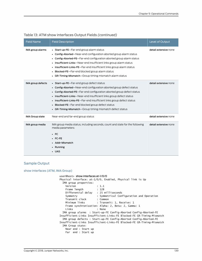
Table 13: ATM show interfaces Output Fields (continued)
Level of OutputField DescriptionField Name
detail extensive none• Start-up-FE—Far-end group alarm status
• Config-Aborted—Near-end configuration aborted group alarm status
• Config-Aborted-FE—Far-end configuration aborted group alarm status
• Insufficient-Links—Near-end insufficient links group alarm status
• Insufficient-Links-FE—Far-end insufficient links group alarm status
• Blocked-FE—Far-end blocked group alarm status
• GR-Timing-Mismatch—Group timing mismatch alarm status
IMA group alarms
detail extensive none• Start-up-FE—Far-end group defect status
• Config-Aborted—Near-end configuration aborted group defect status
• Config-Aborted-FE—Far-end configuration aborted group defect status
• Insufficient-Links—Near-end insufficient links group defect status
• Insufficient-Links-FE—Far-end insufficient links group defect status
• Blocked-FE—Far-end blocked group defect status
• GR-Timing-Mismatch—Group timing mismatch defect status
IMA group defects
detail extensive noneNear-end and far-end group statusIMA Group state
detail extensive noneIMA groupmedia status, including seconds, count and state for the followingmedia parameters:
• FC
• FC-FE
• Addr-Mismatch
• Running
• UAS
IMA groupmedia
Sample Output
show interfaces (ATM, IMAGroup)
user@host> show interfaces at-1/0/0Physical interface: at-1/0/0, Enabled, Physical link is Up IMA group properties: Version : 1.1 Frame length : 128 Differential delay : 25 milliseconds Symmetry : Symmetrical Configuration and Operation Transmit clock : Common Minimum links : Transmit: 1, Receive: 1 Frame synchronization: Alpha: 2, Beta: 2, Gamma: 1 Links : None IMA group alarms : Start-up-FE Config-Aborted Config-Aborted-FE Insufficient-Links Insufficient-Links-FE Blocked-FE GR-Timing-Mismatch IMA group defects : Start-up-FE Config-Aborted Config-Aborted-FE Insufficient-Links Insufficient-Links-FE Blocked-FE GR-Timing-Mismatch IMA Group state: Near end : Start up Far end : Start up
139Copyright © 2018, Juniper Networks, Inc.
Chapter 9: Operational Commands

IMA group media: Seconds Count State FC 0 FC-FE 0 Addr-Mismatch 0 Running 0 UAS 0
show interfaces extensive (ATM IMAGroup)
user@host> show interfaces at-0/0/10 extensivePhysical interface: at-0/0/10, Enabled, Physical link is Up Interface index: 178, SNMP ifIndex: 540, Generation: 531 Link-level type: ATM-PVC, MTU: 2048, Speed: Unspecified, Loopback: None, Payload scrambler: Enabled Device flags : Present Running Link flags : None CoS queues : 8 supported, 4 maximum usable queues Hold-times : Up 0 ms, Down 0 ms Current address: 00:00:5e:00:53:0a Last flapped : 2012-03-16 16:49:15 PDT (2d 07:12 ago) Statistics last cleared: 2012-03-16 16:56:58 PDT (2d 07:05 ago) Traffic statistics: Input bytes : 0 0 bps Output bytes : 0 0 bps Input packets: 0 0 pps Output packets: 0 0 pps IPv6 transit statistics: Input bytes : 0 Output bytes : 0 Input packets: 0 Output packets: 0 Input errors: Errors: 0, Drops: 0, Invalid VCs: 0, Framing errors: 0, Policed discards: 0, L3 incompletes: 0, L2 channel errors: 0, L2 mismatch timeouts: 0, Resource errors: 0 Output errors: Carrier transitions: 0, Errors: 0, Drops: 0, Aged packets: 0, MTU errors: 0, Resource errors: 0 IMA group properties: Version : 1.1 Frame length : 128 Differential delay : 25 milliseconds Symmetry : Symmetrical Configuration and Operation Transmit clock : Common Minimum links : Transmit: 1, Receive: 1 Frame synchronization: Alpha: 2, Beta: 2, Gamma: 1 Link #1 : t1-0/0/4 up IMA Group alarms : None IMA Group defects : None
IMA Group state: Near end : Operational Far end : Operational IMA group media: Seconds Count State FC 0 FC-FE 0 Addr-Mismatch 0 Running 198306 UAS 0 ATM status: HCS state: Sync
Copyright © 2018, Juniper Networks, Inc.140
Circuit Emulation Interfaces Feature Guide for Routing Devices
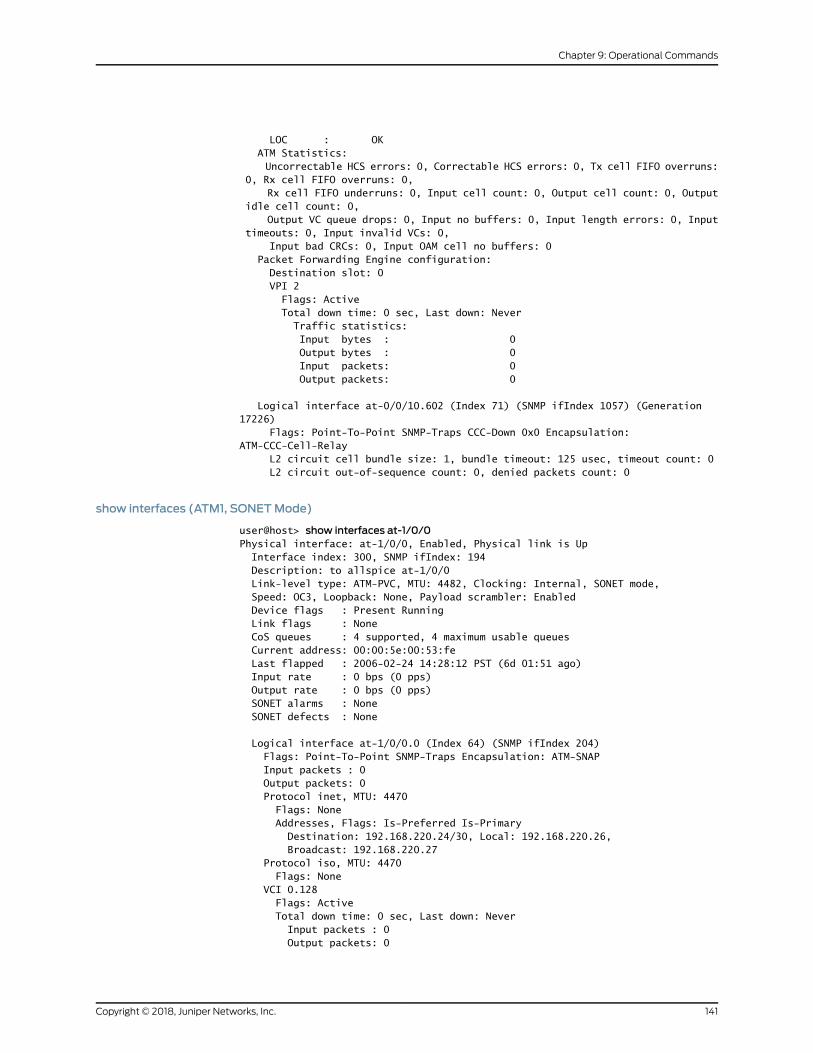
LOC : OK ATM Statistics: Uncorrectable HCS errors: 0, Correctable HCS errors: 0, Tx cell FIFO overruns: 0, Rx cell FIFO overruns: 0, Rx cell FIFO underruns: 0, Input cell count: 0, Output cell count: 0, Output idle cell count: 0, Output VC queue drops: 0, Input no buffers: 0, Input length errors: 0, Input timeouts: 0, Input invalid VCs: 0, Input bad CRCs: 0, Input OAM cell no buffers: 0 Packet Forwarding Engine configuration: Destination slot: 0 VPI 2 Flags: Active Total down time: 0 sec, Last down: Never Traffic statistics: Input bytes : 0 Output bytes : 0 Input packets: 0 Output packets: 0
Logical interface at-0/0/10.602 (Index 71) (SNMP ifIndex 1057) (Generation 17226) Flags: Point-To-Point SNMP-Traps CCC-Down 0x0 Encapsulation: ATM-CCC-Cell-Relay L2 circuit cell bundle size: 1, bundle timeout: 125 usec, timeout count: 0 L2 circuit out-of-sequence count: 0, denied packets count: 0
show interfaces (ATM1, SONETMode)
user@host> show interfaces at-1/0/0Physical interface: at-1/0/0, Enabled, Physical link is Up Interface index: 300, SNMP ifIndex: 194 Description: to allspice at-1/0/0 Link-level type: ATM-PVC, MTU: 4482, Clocking: Internal, SONET mode, Speed: OC3, Loopback: None, Payload scrambler: Enabled Device flags : Present Running Link flags : None CoS queues : 4 supported, 4 maximum usable queues Current address: 00:00:5e:00:53:fe Last flapped : 2006-02-24 14:28:12 PST (6d 01:51 ago) Input rate : 0 bps (0 pps) Output rate : 0 bps (0 pps) SONET alarms : None SONET defects : None
Logical interface at-1/0/0.0 (Index 64) (SNMP ifIndex 204) Flags: Point-To-Point SNMP-Traps Encapsulation: ATM-SNAP Input packets : 0 Output packets: 0 Protocol inet, MTU: 4470 Flags: None Addresses, Flags: Is-Preferred Is-Primary Destination: 192.168.220.24/30, Local: 192.168.220.26, Broadcast: 192.168.220.27 Protocol iso, MTU: 4470 Flags: None VCI 0.128 Flags: Active Total down time: 0 sec, Last down: Never Input packets : 0 Output packets: 0
141Copyright © 2018, Juniper Networks, Inc.
Chapter 9: Operational Commands

show interfaces brief (ATM1, SONETMode)
user@host> show interfaces at-1/0/0 briefPhysical interface: at-1/0/0, Enabled, Physical link is Up Description: to allspice at-1/0/0 Link-level type: ATM-PVC, MTU: 4482, Clocking: Internal, SONET mode, Speed: OC3, Loopback: None, Payload scrambler: Enabled Device flags : Present Running Link flags : None
Logical interface at-1/0/0.0 Flags: Point-To-Point SNMP-Traps Encapsulation: ATM-SNAP inet 192.168.220.26/30 iso VCI 0.128 Flags: Active Total down time: 0 sec, Last down: Never
show interfaces detail (ATM1, SONETMode)
user@host> show interfaces at-1/0/0 detailPhysical interface: at-1/0/0, Enabled, Physical link is Up Interface index: 300, SNMP ifIndex: 194, Generation: 183 Description: to allspice at-1/0/0 Link-level type: ATM-PVC, MTU: 4482, Clocking: Internal, SONET mode, Speed: OC3, Loopback: None, Payload scrambler: Enabled Device flags : Present Running Link flags : None CoS queues : 4 supported, 4 maximum usable queues Hold-times : Up 0 ms, Down 0 ms Current address: 00:00:5e:00:53:fe Last flapped : 2006-02-24 14:28:12 PST (6d 01:55 ago) Statistics last cleared: Never Traffic statistics: Input bytes : 0 0 bps Output bytes : 0 0 bps Input packets: 0 0 pps Output packets: 0 0 pps Egress queues: 4 supported, 4 in use Queue counters: Queued packets Transmitted packets Dropped packets
0 best-effort 0 0 0
1 expedited-fo 0 0 0
2 assured-forw 0 0 0
3 network-cont 0 0 0
SONET alarms : None SONET defects : None
Logical interface at-1/0/0.0 (Index 64) (SNMP ifIndex 204) (Generation 5) Flags: Point-To-Point SNMP-Traps Encapsulation: ATM-SNAP Traffic statistics: Input bytes : 0 Output bytes : 0 Input packets: 0 Output packets: 0 Local statistics:
Copyright © 2018, Juniper Networks, Inc.142
Circuit Emulation Interfaces Feature Guide for Routing Devices
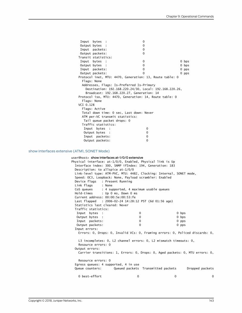
Input bytes : 0 Output bytes : 0 Input packets: 0 Output packets: 0 Transit statistics: Input bytes : 0 0 bps Output bytes : 0 0 bps Input packets: 0 0 pps Output packets: 0 0 pps Protocol inet, MTU: 4470, Generation: 13, Route table: 0 Flags: None Addresses, Flags: Is-Preferred Is-Primary Destination: 192.168.220.24/30, Local: 192.168.220.26, Broadcast: 192.168.220.27, Generation: 14 Protocol iso, MTU: 4470, Generation: 14, Route table: 0 Flags: None VCI 0.128 Flags: Active Total down time: 0 sec, Last down: Never ATM per-VC transmit statistics: Tail queue packet drops: 0 Traffic statistics: Input bytes : 0 Output bytes : 0 Input packets: 0 Output packets: 0
show interfaces extensive (ATM1, SONETMode)
user@host> show interfaces at-1/0/0 extensivePhysical interface: at-1/0/0, Enabled, Physical link is Up Interface index: 300, SNMP ifIndex: 194, Generation: 183 Description: to allspice at-1/0/0 Link-level type: ATM-PVC, MTU: 4482, Clocking: Internal, SONET mode, Speed: OC3, Loopback: None, Payload scrambler: Enabled Device flags : Present Running Link flags : None CoS queues : 4 supported, 4 maximum usable queues Hold-times : Up 0 ms, Down 0 ms Current address: 00:00:5e:00:53:fe Last flapped : 2006-02-24 14:28:12 PST (6d 01:56 ago) Statistics last cleared: Never Traffic statistics: Input bytes : 0 0 bps Output bytes : 0 0 bps Input packets: 0 0 pps Output packets: 0 0 pps Input errors: Errors: 0, Drops: 0, Invalid VCs: 0, Framing errors: 0, Policed discards: 0,
L3 incompletes: 0, L2 channel errors: 0, L2 mismatch timeouts: 0, Resource errors: 0 Output errors: Carrier transitions: 1, Errors: 0, Drops: 0, Aged packets: 0, MTU errors: 0,
Resource errors: 0 Egress queues: 4 supported, 4 in use Queue counters: Queued packets Transmitted packets Dropped packets
0 best-effort 0 0 0
143Copyright © 2018, Juniper Networks, Inc.
Chapter 9: Operational Commands

1 expedited-fo 0 0 0
2 assured-forw 0 0 0
3 network-cont 0 0 0
SONET alarms : None SONET defects : None SONET PHY: Seconds Count State PLL Lock 0 0 OK PHY Light 0 0 OK SONET section: BIP-B1 0 0 SEF 0 0 OK LOS 0 0 OK LOF 0 0 OK ES-S 0 SES-S 0 SEFS-S 0 SONET line: BIP-B2 0 0 REI-L 0 0 RDI-L 0 0 OK AIS-L 0 0 OK BERR-SF 0 0 OK BERR-SD 0 0 OK ES-L 0 SES-L 0 UAS-L 0 ES-LFE 0 SES-LFE 0 UAS-LFE 0 SONET path: BIP-B3 0 0 REI-P 0 0 LOP-P 0 0 OK AIS-P 0 0 OK RDI-P 0 0 OK UNEQ-P 1 1 OK PLM-P 0 0 OK ES-P 1 SES-P 1 UAS-P 0 ES-PFE 0 SES-PFE 0 UAS-PFE 0 Received SONET overhead: F1 : 0x00, J0 : 0x00, K1 : 0x00, K2 : 0x00 S1 : 0x00, C2 : 0x13, C2(cmp) : 0x13, F2 : 0x00 Z3 : 0x00, Z4 : 0x00, S1(cmp) : 0x00 Transmitted SONET overhead: F1 : 0x00, J0 : 0x01, K1 : 0x00, K2 : 0x00 S1 : 0x00, C2 : 0x13, F2 : 0x00, Z3 : 0x00 Z4 : 0x00 ATM status: HCS state: Sync LOC : OK ATM Statistics: Uncorrectable HCS errors: 0, Correctable HCS errors: 0, Tx cell FIFO overruns: 0, Rx cell FIFO overruns: 0, Rx cell FIFO underruns: 0, Input cell count: 0, Output cell count: 0,
Copyright © 2018, Juniper Networks, Inc.144
Circuit Emulation Interfaces Feature Guide for Routing Devices

Output idle cell count: 0, Output VC queue drops: 0, Input no buffers: 0, Input length errors: 0, Input timeouts: 0, Input invalid VCs: 0, Input bad CRCs: 0, Input OAM cell no buffers: 0 Packet Forwarding Engine configuration: Destination slot: 1 CoS information: CoS transmit queue Bandwidth Buffer Priority Limit % bps % usec 0 best-effort 95 147744000 95 0 low none 3 network-control 5 7776000 5 0 low none
Logical interface at-1/0/0.0 (Index 64) (SNMP ifIndex 204) (Generation 5) Flags: Point-To-Point SNMP-Traps Encapsulation: ATM-SNAP Traffic statistics: Input bytes : 0 Output bytes : 0 Input packets: 0 Output packets: 0 Local statistics: Input bytes : 0 Output bytes : 0 Input packets: 0 Output packets: 0 Transit statistics: Input bytes : 0 0 bps Output bytes : 0 0 bps Input packets: 0 0 pps Output packets: 0 0 pps Protocol inet, MTU: 4470, Generation: 13, Route table: 0 Flags: None Addresses, Flags: Is-Preferred Is-Primary Destination: 192.168.220.24/30, Local: 192.168.220.26, Broadcast: 192.168.220.27, Generation: 14 Protocol iso, MTU: 4470, Generation: 14, Route table: 0 Flags: None VCI 0.128 Flags: Active Total down time: 0 sec, Last down: Never ATM per-VC transmit statistics: Tail queue packet drops: 0 Traffic statistics: Input bytes : 0 Output bytes : 0 Input packets: 0 Output packets: 0
show interfaces (ATM2, SDHMode)
user@host> show interfaces at-0/2/1Physical interface: at-0/2/1, Enabled, Physical link is Up Interface index: 154, SNMP ifIndex: 42 Link-level type: ATM-PVC, MTU: 4482, Clocking: Internal, SDH mode, Speed: OC3,
Loopback: None, Payload scrambler: Enabled Device flags : Present Running Link flags : None CoS queues : 4 supported, 4 maximum usable queues Current address: 00:00:5e:00:53:3f Last flapped : 2006-03-24 13:29:58 PST (00:04:48 ago) Input rate : 0 bps (0 pps) Output rate : 0 bps (0 pps)
145Copyright © 2018, Juniper Networks, Inc.
Chapter 9: Operational Commands

SDH alarms : None SDH defects : None VPI 0 Flags: Active Total down time: 0 sec, Last down: Never Traffic statistics: Input packets: 0 Output packets: 0
Logical interface at-0/2/1.0 (Index 75) (SNMP ifIndex 51) Flags: Point-To-Point SNMP-Traps 0x4000 Encapsulation: ATM-SNAP Input packets : 0 Output packets: 0 Protocol inet, MTU: 4470 Flags: None Addresses, Flags: Is-Preferred Is-Primary Destination: 10.0.12.6, Local: 10.0.12.5 Protocol iso, MTU: 4470 Flags: None VCI 0.128 Flags: Active Total down time: 0 sec, Last down: Never EPD threshold: 2129, Transmit weight cells: 0 Input packets : 0 Output packets: 0
Logical interface at-0/2/1.32767 (Index 76) (SNMP ifIndex 50) Flags: Point-To-Multipoint No-Multicast SNMP-Traps 0x4000 Encapsulation: ATM-VCMUX Input packets : 0 Output packets: 0 VCI 0.4 Flags: Active Total down time: 0 sec, Last down: Never EPD threshold: 0, Transmit weight cells: 0 Input packets : 0 Output packets: 0
show interfaces brief (ATM2, SDHMode)
user@host> show interfaces at-0/2/1 briefPhysical interface: at-0/2/1, Enabled, Physical link is Up Link-level type: ATM-PVC, MTU: 4482, Clocking: Internal, SDH mode, Speed: OC3, Loopback: None, Payload scrambler: Enabled Device flags : Present Running Link flags : None Logical interface at-0/2/1.0 Flags: Point-To-Point SNMP-Traps 0x4000 Encapsulation: ATM-SNAP inet 10.0.12.5 --> 10.0.12.6 iso VCI 0.128 Flags: Active Total down time: 0 sec, Last down: Never EPD threshold: 2129, Transmit weight cells: 0
Logical interface at-0/2/1.32767 Flags: Point-To-Multipoint No-Multicast SNMP-Traps 0x4000 Encapsulation: ATM-VCMUX VCI 0.4 Flags: Active
Copyright © 2018, Juniper Networks, Inc.146
Circuit Emulation Interfaces Feature Guide for Routing Devices

Total down time: 0 sec, Last down: Never EPD threshold: 0, Transmit weight cells: 0
show interfaces detail (ATM2, SDHMode)
user@host> show interfaces at-0/2/1 detailPhysical interface: at-0/2/1, Enabled, Physical link is Up Interface index: 154, SNMP ifIndex: 42, Generation: 40 Link-level type: ATM-PVC, MTU: 4482, Clocking: Internal, SDH mode, Speed: OC3,
Loopback: None, Payload scrambler: Enabled Device flags : Present Running Link flags : None CoS queues : 4 supported, 4 maximum usable queues Hold-times : Up 0 ms, Down 0 ms Current address: 00:00:5e:00:53:3f Last flapped : 2006-03-24 13:29:58 PST (00:05:10 ago) Statistics last cleared: Never Traffic statistics: Input bytes : 0 0 bps Output bytes : 0 0 bps Input packets: 0 0 pps Output packets: 0 0 pps Egress queues: 4 supported, 4 in use Queue counters: Queued packets Transmitted packets Dropped packets
0 best-effort 0 0 0
1 expedited-fo 0 0 0
2 assured-forw 0 0 0
3 network-cont 0 0 0
SDH alarms : None SDH defects : None VPI 0 Flags: Active Total down time: 0 sec, Last down: Never Traffic statistics: Input bytes : 0 Output bytes : 0 Input packets: 0 Output packets: 0
Logical interface at-0/2/1.0 (Index 75) (SNMP ifIndex 51) (Generation 25) Flags: Point-To-Point SNMP-Traps 0x4000 Encapsulation: ATM-SNAP Traffic statistics: Input bytes : 0 Output bytes : 0 Input packets: 0 Output packets: 0 Local statistics: Input bytes : 0 Output bytes : 0 Input packets: 0 Output packets: 0 Transit statistics: Input bytes : 0 0 bps Output bytes : 0 0 bps Input packets: 0 0 pps
147Copyright © 2018, Juniper Networks, Inc.
Chapter 9: Operational Commands

Output packets: 0 0 pps Protocol inet, MTU: 4470, Generation: 62, Route table: 0 Flags: None Addresses, Flags: Is-Preferred Is-Primary Destination: 10.0.12.6, Local: 10.0.12.5, Broadcast: Unspecified, Generation: 58 Protocol iso, MTU: 4470, Generation: 63, Route table: 0 Flags: None VCI 0.128 Flags: Active Total down time: 0 sec, Last down: Never EPD threshold: 2129, Transmit weight cells: 0 ATM per-VC transmit statistics: Tail queue packet drops: 0 Traffic statistics: Input bytes : 0 Output bytes : 0 Input packets: 0 Output packets: 0 Logical interface at-0/2/1.32767 (Index 76) (SNMP ifIndex 50) (Generation 26) Flags: Point-To-Multipoint No-Multicast SNMP-Traps 0x4000 Encapsulation: ATM-VCMUX Traffic statistics: Input bytes : 0 Output bytes : 0 Input packets: 0 Output packets: 0 Local statistics: Input bytes : 0 Output bytes : 0 Input packets: 0 Output packets: 0 VCI 0.4 Flags: Active Total down time: 0 sec, Last down: Never EPD threshold: 0, Transmit weight cells: 0 ATM per-VC transmit statistics: Tail queue packet drops: 0 Traffic statistics: Input bytes : 0 Output bytes : 0 Input packets: 0 Output packets: 0
show interfaces extensive (ATM2, SDHMode)
user@host> show interfaces at-0/2/1 extensivePhysical interface: at-0/2/1, Enabled, Physical link is Up Interface index: 154, SNMP ifIndex: 42, Generation: 40 Link-level type: ATM-PVC, MTU: 4482, Clocking: Internal, SDH mode, Speed: OC3,
Loopback: None, Payload scrambler: Enabled Device flags : Present Running Link flags : None CoS queues : 4 supported, 4 maximum usable queues Hold-times : Up 0 ms, Down 0 ms Current address: 00:00:5e:00:53:3f Last flapped : 2006-03-24 13:29:58 PST (00:06:49 ago) Statistics last cleared: Never Traffic statistics: Input bytes : 0 0 bps
Copyright © 2018, Juniper Networks, Inc.148
Circuit Emulation Interfaces Feature Guide for Routing Devices
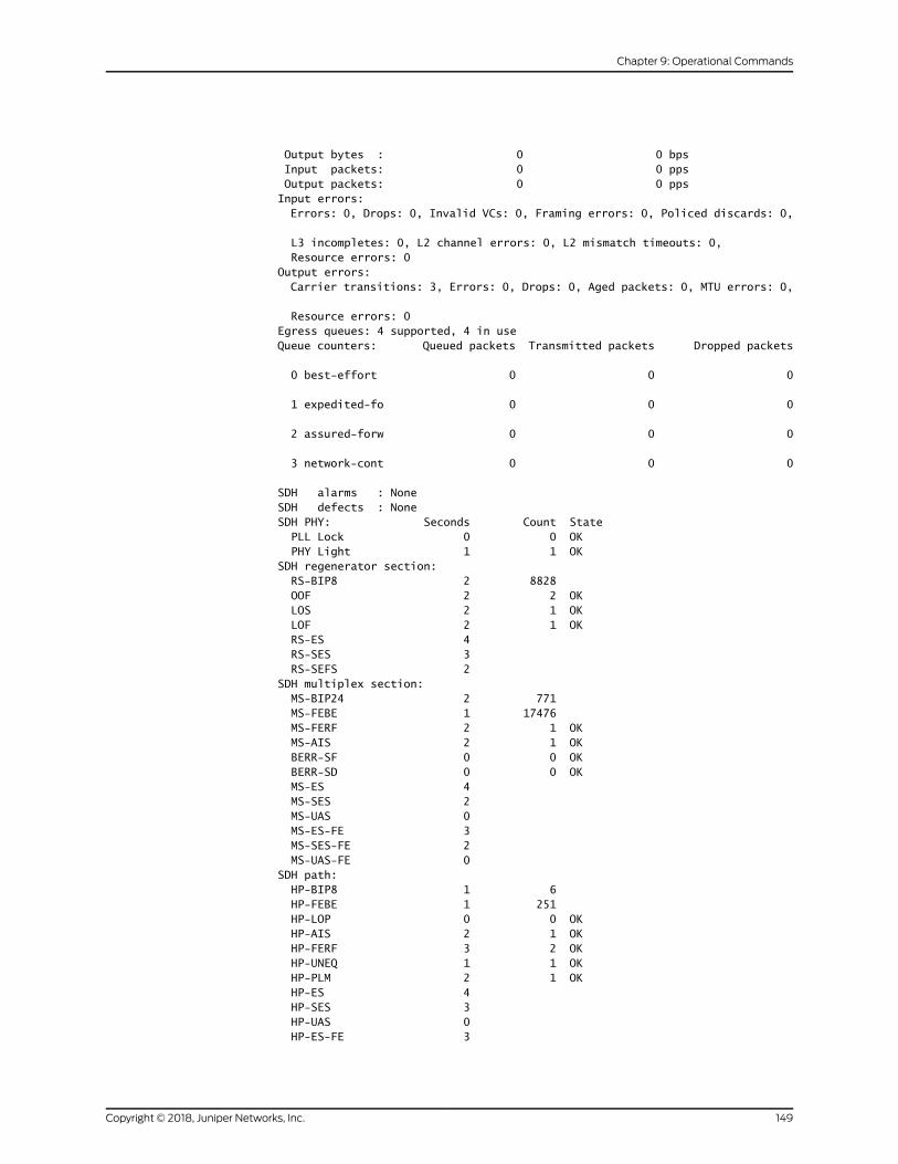
Output bytes : 0 0 bps Input packets: 0 0 pps Output packets: 0 0 pps Input errors: Errors: 0, Drops: 0, Invalid VCs: 0, Framing errors: 0, Policed discards: 0,
L3 incompletes: 0, L2 channel errors: 0, L2 mismatch timeouts: 0, Resource errors: 0 Output errors: Carrier transitions: 3, Errors: 0, Drops: 0, Aged packets: 0, MTU errors: 0,
Resource errors: 0 Egress queues: 4 supported, 4 in use Queue counters: Queued packets Transmitted packets Dropped packets
0 best-effort 0 0 0
1 expedited-fo 0 0 0
2 assured-forw 0 0 0
3 network-cont 0 0 0
SDH alarms : None SDH defects : None SDH PHY: Seconds Count State PLL Lock 0 0 OK PHY Light 1 1 OK SDH regenerator section: RS-BIP8 2 8828 OOF 2 2 OK LOS 2 1 OK LOF 2 1 OK RS-ES 4 RS-SES 3 RS-SEFS 2 SDH multiplex section: MS-BIP24 2 771 MS-FEBE 1 17476 MS-FERF 2 1 OK MS-AIS 2 1 OK BERR-SF 0 0 OK BERR-SD 0 0 OK MS-ES 4 MS-SES 2 MS-UAS 0 MS-ES-FE 3 MS-SES-FE 2 MS-UAS-FE 0 SDH path: HP-BIP8 1 6 HP-FEBE 1 251 HP-LOP 0 0 OK HP-AIS 2 1 OK HP-FERF 3 2 OK HP-UNEQ 1 1 OK HP-PLM 2 1 OK HP-ES 4 HP-SES 3 HP-UAS 0 HP-ES-FE 3
149Copyright © 2018, Juniper Networks, Inc.
Chapter 9: Operational Commands

HP-SES-FE 3 HP-UAS-FE 0 Received SDH overhead: F1 : 0x00, J0 : 0x00, K1 : 0x00, K2 : 0x00 S1 : 0x00, C2 : 0x13, C2(cmp) : 0x13, F2 : 0x00 Z3 : 0x00, Z4 : 0x00, S1(cmp) : 0x00 Transmitted SDH overhead: F1 : 0x00, J0 : 0x01, K1 : 0x00, K2 : 0x00 S1 : 0x00, C2 : 0x13, F2 : 0x00, Z3 : 0x00 Z4 : 0x00 ATM status: HCS state: Sync LOC : OK ATM Statistics: Uncorrectable HCS errors: 0, Correctable HCS errors: 0, Tx cell FIFO overruns: 0, Rx cell FIFO overruns: 0, Rx cell FIFO underruns: 0, Input cell count: 0, Output cell count: 0, Output idle cell count: 0, Output VC queue drops: 0, Input no buffers: 0, Input length errors: 0, Input timeouts: 0, Input invalid VCs: 0, Input bad CRCs: 0, Input OAM cell no buffers: 0 Packet Forwarding Engine configuration: Destination slot: 0 VPI 0 Flags: Active Total down time: 0 sec, Last down: Never Traffic statistics: Input bytes : 0 Output bytes : 0 Input packets: 0 Output packets: 0
Logical interface at-0/2/1.0 (Index 75) (SNMP ifIndex 51) (Generation 25) Flags: Point-To-Point SNMP-Traps 0x4000 Encapsulation: ATM-SNAP Traffic statistics: Input bytes : 0 Output bytes : 0 Input packets: 0 Output packets: 0 Local statistics: Input bytes : 0 Output bytes : 0 Input packets: 0 Output packets: 0 Transit statistics: Input bytes : 0 0 bps Output bytes : 0 0 bps Input packets: 0 0 pps Output packets: 0 0 pps Protocol inet, MTU: 4470, Generation: 62, Route table: 0 Flags: None Addresses, Flags: Is-Preferred Is-Primary Destination: 10.0.12.6, Local: 10.0.12.5, Broadcast: Unspecified, Generation: 58 Protocol iso, MTU: 4470, Generation: 63, Route table: 0 Flags: None VCI 0.128 Flags: Active Total down time: 0 sec, Last down: Never EPD threshold: 2129, Transmit weight cells: 0 ATM per-VC transmit statistics: Tail queue packet drops: 0
Copyright © 2018, Juniper Networks, Inc.150
Circuit Emulation Interfaces Feature Guide for Routing Devices

Traffic statistics: Input bytes : 0 Output bytes : 0 Input packets: 0 Output packets: 0 Logical interface at-0/2/1.32767 (Index 76) (SNMP ifIndex 50) (Generation 26) Flags: Point-To-Multipoint No-Multicast SNMP-Traps 0x4000 Encapsulation: ATM-VCMUX Traffic statistics: Input bytes : 0 Output bytes : 0 Input packets: 0 Output packets: 0 Local statistics: Input bytes : 0 Output bytes : 0 Input packets: 0 Output packets: 0 VCI 0.4 Flags: Active Total down time: 0 sec, Last down: Never EPD threshold: 0, Transmit weight cells: 0 ATM per-VC transmit statistics: Tail queue packet drops: 0 Traffic statistics: Input bytes : 0 Output bytes : 0 Input packets: 0 Output packets: 0
show interfaces (ATM2, SONETMode)
user@host> show interfaces at-0/3/1Physical interface: at-0/3/1, Enabled, Physical link is Up Interface index: 139, SNMP ifIndex: 67 Link-level type: ATM-PVC, MTU: 4482, Clocking: Internal, SONET mode, Speed: OC3, Loopback: None, Payload scrambler: Enabled Device flags : Present Running Link flags : None CoS queues : 4 supported, 4 maximum usable queues Current address: 00:00:5e:00:53:5e Last flapped : 2006-03-13 17:46:36 PST (16:01:12 ago) Input rate : 0 bps (0 pps) Output rate : 0 bps (0 pps) SONET alarms : None SONET defects : None VPI 0 Flags: Active, OAM, Shaping CBR, Peak: 50kbps OAM, Period 30 sec, Up count: 10, Down count: 10 Total down time: 0 sec, Last down: Never OAM F4 cell statistics: Total received: 4, Total sent: 4 Loopback received: 4, Loopback sent: 4 RDI received: 0, RDI sent: 0 AIS received: 0 Traffic statistics: Input packets: 4 Output packets: 30 VPI 10 Flags: Active
151Copyright © 2018, Juniper Networks, Inc.
Chapter 9: Operational Commands

Total down time: 0 sec, Last down: Never Traffic statistics: Input packets: 0 Output packets: 0 Logical interface at-0/3/1.0 (Index 78) (SNMP ifIndex 77) Flags: Point-To-Point Copy-PLP-To-CLP SNMP-Traps 0x4000 Encapsulation: ATM-SNAP Input packets : 0 Output packets: 0 Protocol inet, MTU: 4470 Flags: None Addresses, Flags: Is-Preferred Is-Primary Destination: 10.0.59.5, Local: 10.0.59.6 Protocol iso, MTU: 4470 Flags: None VCI 0.128 Flags: Active Total down time: 0 sec, Last down: Never EPD threshold: 2129, Transmit weight cells: 10 Input packets : 0 Output packets: 0
Logical interface at-0/3/1.32767 (Index 79) (SNMP ifIndex 76) Flags: Point-To-Multipoint Copy-PLP-To-CLP No-Multicast SNMP-Traps 0x4000 Encapsulation: ATM-VCMUX Input packets : 4 Output packets: 30 VCI 0.16 Flags: Active, ILMI Total down time: 0 sec, Last down: Never EPD threshold: 0, Transmit weight cells: 0 Input packets : 0 Output packets: 26 VCI 0.4 Flags: Active, OAM OAM, Period 30 sec, Up count: 10, Down count: 10 Total down time: 0 sec, Last down: Never EPD threshold: 2129, Transmit weight cells: 0 Input packets : 4 Output packets: 4 OAM F4 cell statistics: Total received: 4, Total sent: 4 Loopback received: 4, Loopback sent: 4 RDI received: 0, RDI sent: 0 AIS received: 0, AIS sent: 0
show interfaces brief (ATM2, SONETMode)
user@host> show interfaces at-0/3/1 briefPhysical interface: at-0/3/1, Enabled, Physical link is Up Link-level type: ATM-PVC, MTU: 4482, Clocking: Internal, SONET mode, Speed: OC3, Loopback: None, Payload scrambler: Enabled Device flags : Present Running Link flags : None
Logical interface at-0/3/1.0 Flags: Point-To-Point Copy-PLP-To-CLP SNMP-Traps 0x4000 Encapsulation: ATM-SNAP inet 10.0.59.6 --> 10.0.59.5 iso VCI 0.128
Copyright © 2018, Juniper Networks, Inc.152
Circuit Emulation Interfaces Feature Guide for Routing Devices
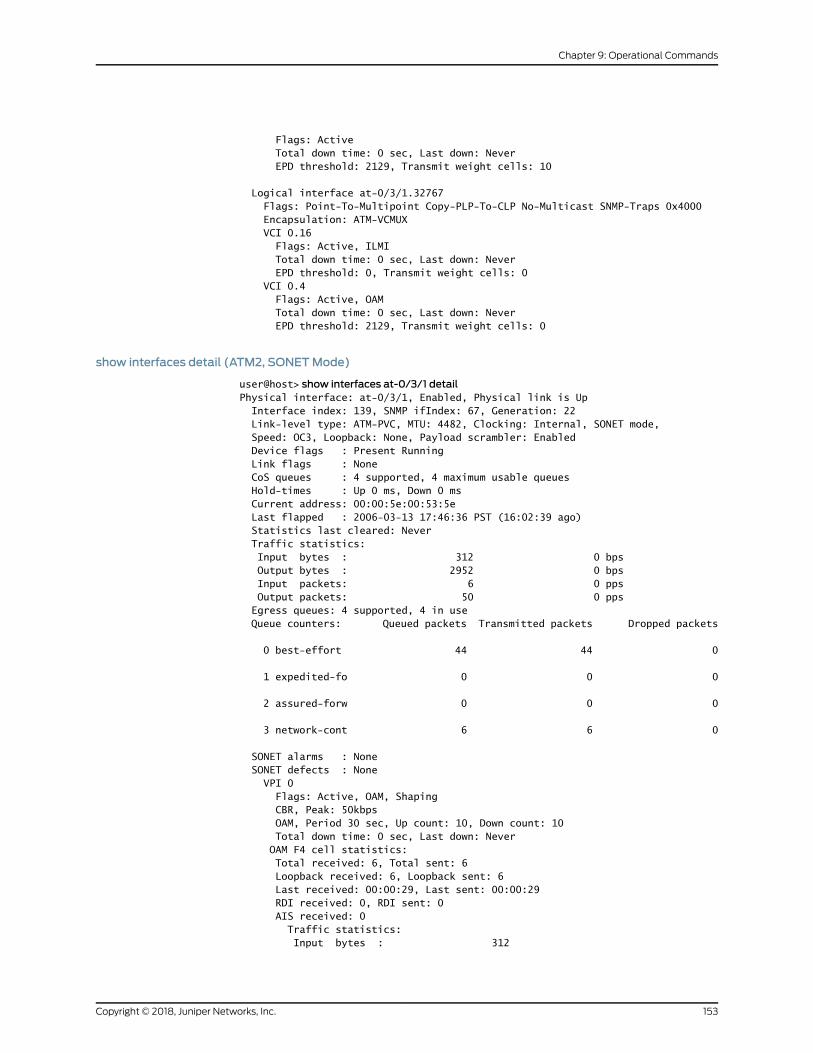
Flags: Active Total down time: 0 sec, Last down: Never EPD threshold: 2129, Transmit weight cells: 10
Logical interface at-0/3/1.32767 Flags: Point-To-Multipoint Copy-PLP-To-CLP No-Multicast SNMP-Traps 0x4000 Encapsulation: ATM-VCMUX VCI 0.16 Flags: Active, ILMI Total down time: 0 sec, Last down: Never EPD threshold: 0, Transmit weight cells: 0 VCI 0.4 Flags: Active, OAM Total down time: 0 sec, Last down: Never EPD threshold: 2129, Transmit weight cells: 0
show interfaces detail (ATM2, SONETMode)
user@host> show interfaces at-0/3/1 detailPhysical interface: at-0/3/1, Enabled, Physical link is Up Interface index: 139, SNMP ifIndex: 67, Generation: 22 Link-level type: ATM-PVC, MTU: 4482, Clocking: Internal, SONET mode, Speed: OC3, Loopback: None, Payload scrambler: Enabled Device flags : Present Running Link flags : None CoS queues : 4 supported, 4 maximum usable queues Hold-times : Up 0 ms, Down 0 ms Current address: 00:00:5e:00:53:5e Last flapped : 2006-03-13 17:46:36 PST (16:02:39 ago) Statistics last cleared: Never Traffic statistics: Input bytes : 312 0 bps Output bytes : 2952 0 bps Input packets: 6 0 pps Output packets: 50 0 pps Egress queues: 4 supported, 4 in use Queue counters: Queued packets Transmitted packets Dropped packets
0 best-effort 44 44 0
1 expedited-fo 0 0 0
2 assured-forw 0 0 0
3 network-cont 6 6 0
SONET alarms : None SONET defects : None VPI 0 Flags: Active, OAM, Shaping CBR, Peak: 50kbps OAM, Period 30 sec, Up count: 10, Down count: 10 Total down time: 0 sec, Last down: Never OAM F4 cell statistics: Total received: 6, Total sent: 6 Loopback received: 6, Loopback sent: 6 Last received: 00:00:29, Last sent: 00:00:29 RDI received: 0, RDI sent: 0 AIS received: 0 Traffic statistics: Input bytes : 312
153Copyright © 2018, Juniper Networks, Inc.
Chapter 9: Operational Commands

Output bytes : 2952 Input packets: 6 Output packets: 50 VPI 10 Flags: Active Total down time: 0 sec, Last down: Never Traffic statistics: Input bytes : 0 Output bytes : 0 Input packets: 0 Output packets: 0
Logical interface at-0/3/1.0 (Index 78) (SNMP ifIndex 77) (Generation 20) Flags: Point-To-Point Copy-PLP-To-CLP SNMP-Traps 0x4000 Encapsulation: ATM-SNAP Traffic statistics: Input bytes : 0 Output bytes : 0 Input packets: 0 Output packets: 0 Local statistics: Input bytes : 0 Output bytes : 0 Input packets: 0 Output packets: 0 Transit statistics: Input bytes : 0 0 bps Output bytes : 0 0 bps Input packets: 0 0 pps Output packets: 0 0 pps Protocol inet, MTU: 4470, Generation: 38, Route table: 0 Flags: None Addresses, Flags: Is-Preferred Is-Primary Destination: 10.0.59.5, Local: 10.0.59.6, Broadcast: Unspecified, Generation: 44 Protocol iso, MTU: 4470, Generation: 39, Route table: 0 Flags: None VCI 0.128 Flags: Active Total down time: 0 sec, Last down: Never EPD threshold: 2129, Transmit weight cells: 10 ATM per-VC transmit statistics: Tail queue packet drops: 0 Traffic statistics: Input bytes : 0 Output bytes : 0 Input packets: 0 Output packets: 0 Logical interface at-0/3/1.32767 (Index 79) (SNMP ifIndex 76) (Generation 21) Flags: Point-To-Multipoint Copy-PLP-To-CLP No-Multicast SNMP-Traps 0x4000 Encapsulation: ATM-VCMUX Traffic statistics: Input bytes : 360 Output bytes : 3302 Input packets: 6 Output packets: 50 Local statistics: Input bytes : 360 Output bytes : 3302 Input packets: 6 Output packets: 50
Copyright © 2018, Juniper Networks, Inc.154
Circuit Emulation Interfaces Feature Guide for Routing Devices
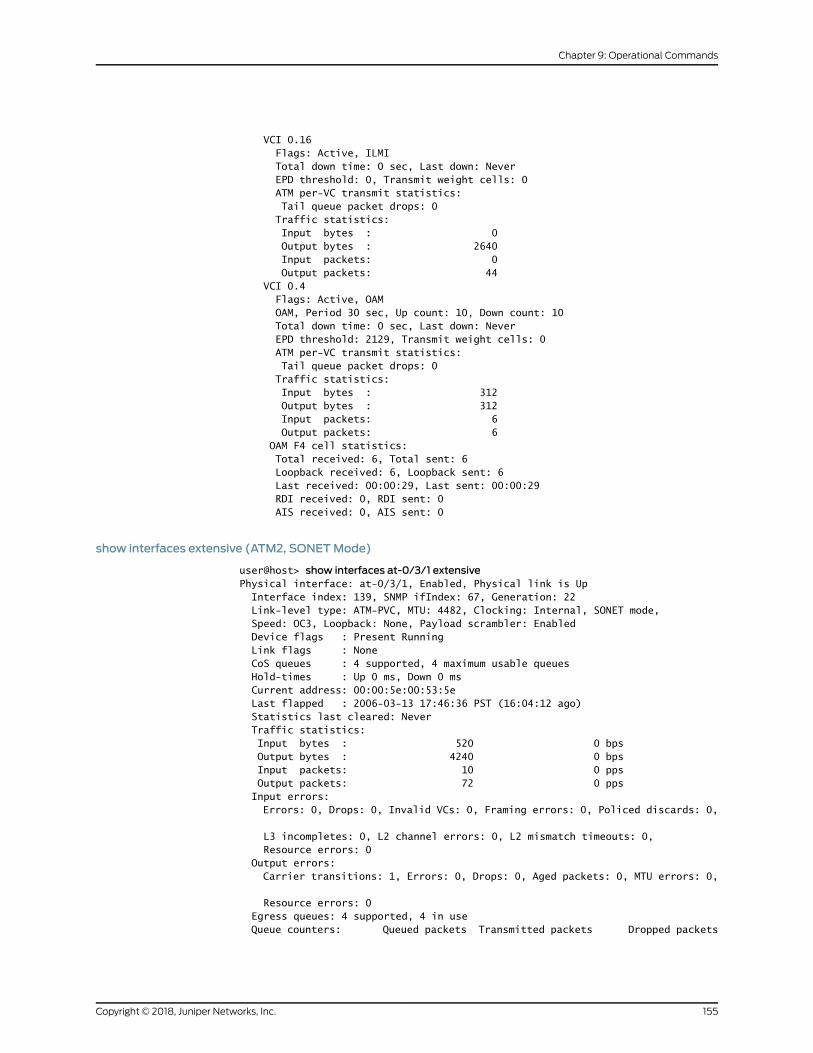
VCI 0.16 Flags: Active, ILMI Total down time: 0 sec, Last down: Never EPD threshold: 0, Transmit weight cells: 0 ATM per-VC transmit statistics: Tail queue packet drops: 0 Traffic statistics: Input bytes : 0 Output bytes : 2640 Input packets: 0 Output packets: 44 VCI 0.4 Flags: Active, OAM OAM, Period 30 sec, Up count: 10, Down count: 10 Total down time: 0 sec, Last down: Never EPD threshold: 2129, Transmit weight cells: 0 ATM per-VC transmit statistics: Tail queue packet drops: 0 Traffic statistics: Input bytes : 312 Output bytes : 312 Input packets: 6 Output packets: 6 OAM F4 cell statistics: Total received: 6, Total sent: 6 Loopback received: 6, Loopback sent: 6 Last received: 00:00:29, Last sent: 00:00:29 RDI received: 0, RDI sent: 0 AIS received: 0, AIS sent: 0
show interfaces extensive (ATM2, SONETMode)
user@host> show interfaces at-0/3/1 extensivePhysical interface: at-0/3/1, Enabled, Physical link is Up Interface index: 139, SNMP ifIndex: 67, Generation: 22 Link-level type: ATM-PVC, MTU: 4482, Clocking: Internal, SONET mode, Speed: OC3, Loopback: None, Payload scrambler: Enabled Device flags : Present Running Link flags : None CoS queues : 4 supported, 4 maximum usable queues Hold-times : Up 0 ms, Down 0 ms Current address: 00:00:5e:00:53:5e Last flapped : 2006-03-13 17:46:36 PST (16:04:12 ago) Statistics last cleared: Never Traffic statistics: Input bytes : 520 0 bps Output bytes : 4240 0 bps Input packets: 10 0 pps Output packets: 72 0 pps Input errors: Errors: 0, Drops: 0, Invalid VCs: 0, Framing errors: 0, Policed discards: 0,
L3 incompletes: 0, L2 channel errors: 0, L2 mismatch timeouts: 0, Resource errors: 0 Output errors: Carrier transitions: 1, Errors: 0, Drops: 0, Aged packets: 0, MTU errors: 0,
Resource errors: 0 Egress queues: 4 supported, 4 in use Queue counters: Queued packets Transmitted packets Dropped packets
155Copyright © 2018, Juniper Networks, Inc.
Chapter 9: Operational Commands
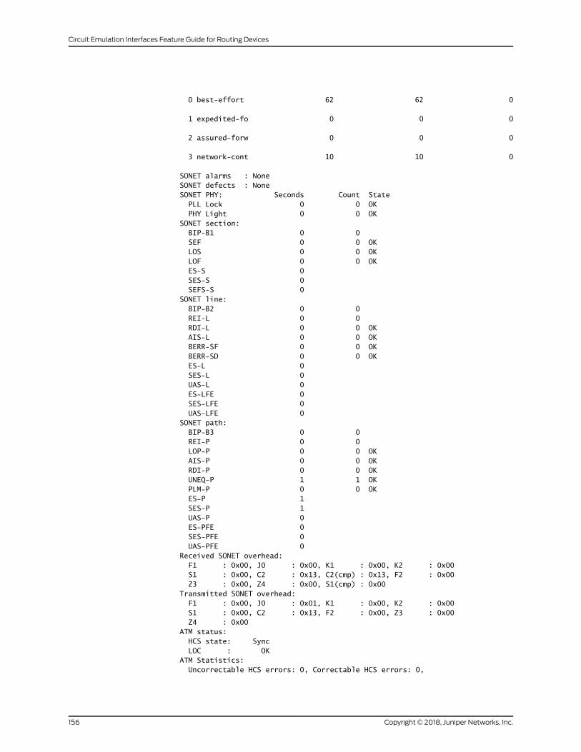
0 best-effort 62 62 0
1 expedited-fo 0 0 0
2 assured-forw 0 0 0
3 network-cont 10 10 0
SONET alarms : None SONET defects : None SONET PHY: Seconds Count State PLL Lock 0 0 OK PHY Light 0 0 OK SONET section: BIP-B1 0 0 SEF 0 0 OK LOS 0 0 OK LOF 0 0 OK ES-S 0 SES-S 0 SEFS-S 0 SONET line: BIP-B2 0 0 REI-L 0 0 RDI-L 0 0 OK AIS-L 0 0 OK BERR-SF 0 0 OK BERR-SD 0 0 OK ES-L 0 SES-L 0 UAS-L 0 ES-LFE 0 SES-LFE 0 UAS-LFE 0 SONET path: BIP-B3 0 0 REI-P 0 0 LOP-P 0 0 OK AIS-P 0 0 OK RDI-P 0 0 OK UNEQ-P 1 1 OK PLM-P 0 0 OK ES-P 1 SES-P 1 UAS-P 0 ES-PFE 0 SES-PFE 0 UAS-PFE 0 Received SONET overhead: F1 : 0x00, J0 : 0x00, K1 : 0x00, K2 : 0x00 S1 : 0x00, C2 : 0x13, C2(cmp) : 0x13, F2 : 0x00 Z3 : 0x00, Z4 : 0x00, S1(cmp) : 0x00 Transmitted SONET overhead: F1 : 0x00, J0 : 0x01, K1 : 0x00, K2 : 0x00 S1 : 0x00, C2 : 0x13, F2 : 0x00, Z3 : 0x00 Z4 : 0x00 ATM status: HCS state: Sync LOC : OK ATM Statistics: Uncorrectable HCS errors: 0, Correctable HCS errors: 0,
Copyright © 2018, Juniper Networks, Inc.156
Circuit Emulation Interfaces Feature Guide for Routing Devices
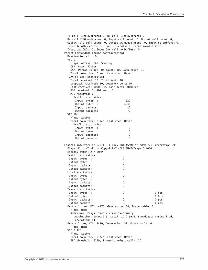
Tx cell FIFO overruns: 0, Rx cell FIFO overruns: 0, Rx cell FIFO underruns: 0, Input cell count: 0, Output cell count: 0, Output idle cell count: 0, Output VC queue drops: 0, Input no buffers: 0, Input length errors: 0, Input timeouts: 0, Input invalid VCs: 0, Input bad CRCs: 0, Input OAM cell no buffers: 0 Packet Forwarding Engine configuration: Destination slot: 0 VPI 0 Flags: Active, OAM, Shaping CBR, Peak: 50kbps OAM, Period 30 sec, Up count: 10, Down count: 10 Total down time: 0 sec, Last down: Never OAM F4 cell statistics: Total received: 10, Total sent: 10 Loopback received: 10, Loopback sent: 10 Last received: 00:00:02, Last sent: 00:00:02 RDI received: 0, RDI sent: 0 AIS received: 0 Traffic statistics: Input bytes : 520 Output bytes : 4240 Input packets: 10 Output packets: 72 VPI 10 Flags: Active Total down time: 0 sec, Last down: Never Traffic statistics: Input bytes : 0 Output bytes : 0 Input packets: 0 Output packets: 0
Logical interface at-0/3/1.0 (Index 78) (SNMP ifIndex 77) (Generation 20) Flags: Point-To-Point Copy-PLP-To-CLP SNMP-Traps 0x4000 Encapsulation: ATM-SNAP Traffic statistics: Input bytes : 0 Output bytes : 0 Input packets: 0 Output packets: 0 Local statistics: Input bytes : 0 Output bytes : 0 Input packets: 0 Output packets: 0 Transit statistics: Input bytes : 0 0 bps Output bytes : 0 0 bps Input packets: 0 0 pps Output packets: 0 0 pps Protocol inet, MTU: 4470, Generation: 38, Route table: 0 Flags: None Addresses, Flags: Is-Preferred Is-Primary Destination: 10.0.59.5, Local: 10.0.59.6, Broadcast: Unspecified, Generation: 44 Protocol iso, MTU: 4470, Generation: 39, Route table: 0 Flags: None VCI 0.128 Flags: Active Total down time: 0 sec, Last down: Never EPD threshold: 2129, Transmit weight cells: 10
157Copyright © 2018, Juniper Networks, Inc.
Chapter 9: Operational Commands
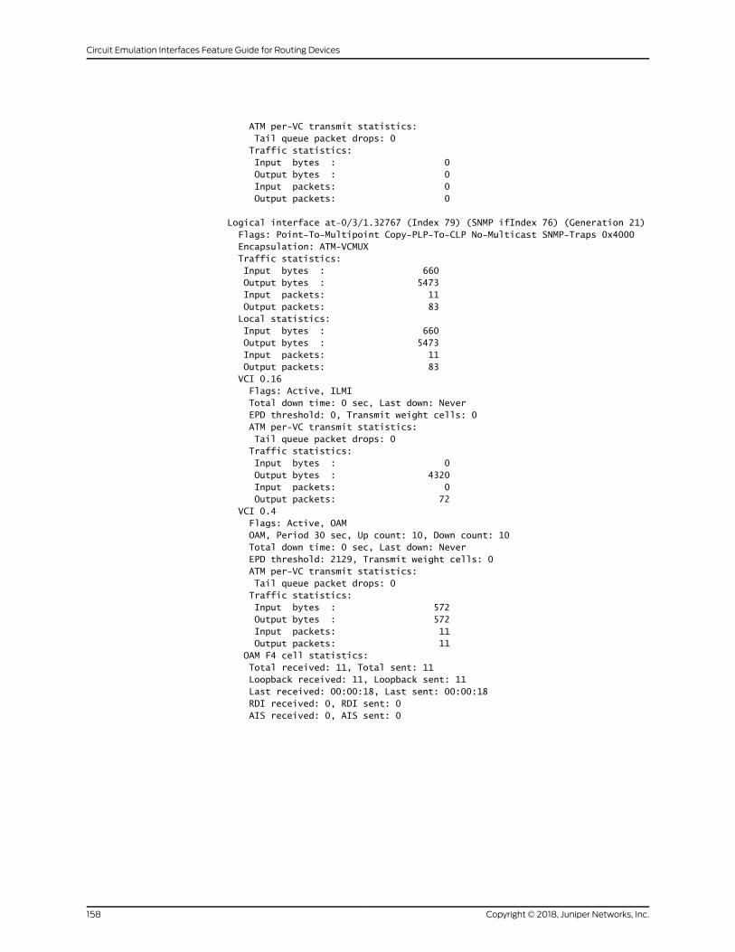
ATM per-VC transmit statistics: Tail queue packet drops: 0 Traffic statistics: Input bytes : 0 Output bytes : 0 Input packets: 0 Output packets: 0
Logical interface at-0/3/1.32767 (Index 79) (SNMP ifIndex 76) (Generation 21) Flags: Point-To-Multipoint Copy-PLP-To-CLP No-Multicast SNMP-Traps 0x4000 Encapsulation: ATM-VCMUX Traffic statistics: Input bytes : 660 Output bytes : 5473 Input packets: 11 Output packets: 83 Local statistics: Input bytes : 660 Output bytes : 5473 Input packets: 11 Output packets: 83 VCI 0.16 Flags: Active, ILMI Total down time: 0 sec, Last down: Never EPD threshold: 0, Transmit weight cells: 0 ATM per-VC transmit statistics: Tail queue packet drops: 0 Traffic statistics: Input bytes : 0 Output bytes : 4320 Input packets: 0 Output packets: 72 VCI 0.4 Flags: Active, OAM OAM, Period 30 sec, Up count: 10, Down count: 10 Total down time: 0 sec, Last down: Never EPD threshold: 2129, Transmit weight cells: 0 ATM per-VC transmit statistics: Tail queue packet drops: 0 Traffic statistics: Input bytes : 572 Output bytes : 572 Input packets: 11 Output packets: 11 OAM F4 cell statistics: Total received: 11, Total sent: 11 Loopback received: 11, Loopback sent: 11 Last received: 00:00:18, Last sent: 00:00:18 RDI received: 0, RDI sent: 0 AIS received: 0, AIS sent: 0
Copyright © 2018, Juniper Networks, Inc.158
Circuit Emulation Interfaces Feature Guide for Routing Devices

show interfaces (T1, E1, or DS)
Syntax show interfaces interface-type<brief | detail | extensive | terse><descriptions><media><snmp-index snmp-index><statistics>
Release Information Command introduced before Junos OS Release 7.4.
Description Display status information about the specified T1, E1, or DS interface.
Options interface-type—OnACXSeries,MSeries,MXSeries, andTSeries routers, the T1 interface
type is t1-fpc/pic/port, whereas the E1 interface type is e1-fpc/pic/port, and DS
interface type is ds-fpc/pic/port:<channel>.
brief | detail | extensive | terse—(Optional) Display the specified level of output.
descriptions—(Optional) Display interface description strings.
media—(Optional) Display media-specific information about network interfaces.
snmp-index snmp-index—(Optional) Display information for the specified SNMP indexof the interface.
statistics—(Optional) Display static interface statistics.
Required PrivilegeLevel
view
RelatedDocumentation
Understanding Interfaces on ACX Series Universal Access Routers•
List of Sample Output show interfaces (T1, IMA Link) on page 171show interfaces (T1, PPP) on page 172show interfaces detail (T1, PPP) on page 172show interfaces extensive (T1 CRC Errors) on page 173show interfaces extensive (T1, PPP) on page 173show interfaces (E1, Frame Relay) on page 175show interfaces detail (E1, Frame Relay) on page 176show interfaces extensive (E1, Frame Relay) on page 177show interfaces (E1, IMA Link) on page 179show interfaces extensive (T1, TDM-CCC-SATOP) on page 180show interfaces extensive (DS, TDM-CCC-CESoPSN) on page 182
Output Fields Table 14 on page 160 lists the output fields for the show interfaces (T1 or E1) command.
Output fields are listed in the approximate order in which they appear.
159Copyright © 2018, Juniper Networks, Inc.
Chapter 9: Operational Commands
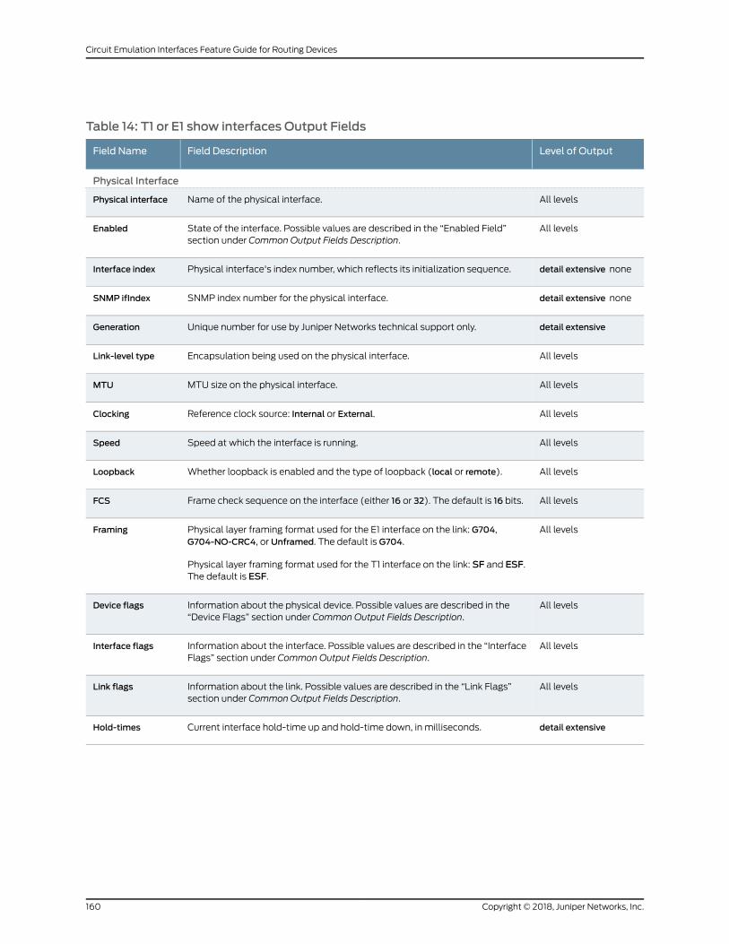
Table 14: T1 or E1 show interfaces Output Fields
Level of OutputField DescriptionField Name
Physical Interface
All levelsName of the physical interface.Physical interface
All levelsState of the interface. Possible values are described in the “Enabled Field”section under Common Output Fields Description.
Enabled
detail extensive nonePhysical interface's index number, which reflects its initialization sequence.Interface index
detail extensive noneSNMP index number for the physical interface.SNMP ifIndex
detail extensiveUnique number for use by Juniper Networks technical support only.Generation
All levelsEncapsulation being used on the physical interface.Link-level type
All levelsMTU size on the physical interface.MTU
All levelsReference clock source: Internal or External.Clocking
All levelsSpeed at which the interface is running.Speed
All levelsWhether loopback is enabled and the type of loopback (local or remote).Loopback
All levelsFrame check sequence on the interface (either 16 or 32). The default is 16 bits.FCS
All levelsPhysical layer framing format used for the E1 interface on the link: G704,G704-NO-CRC4, or Unframed. The default is G704.
Physical layer framing format used for the T1 interface on the link: SF and ESF.The default is ESF.
Framing
All levelsInformation about the physical device. Possible values are described in the“Device Flags” section under Common Output Fields Description.
Device flags
All levelsInformation about the interface. Possible values are described in the “InterfaceFlags” section under Common Output Fields Description.
Interface flags
All levelsInformation about the link. Possible values are described in the “Link Flags”section under Common Output Fields Description.
Link flags
detail extensiveCurrent interface hold-time up and hold-time down, in milliseconds.Hold-times
Copyright © 2018, Juniper Networks, Inc.160
Circuit Emulation Interfaces Feature Guide for Routing Devices
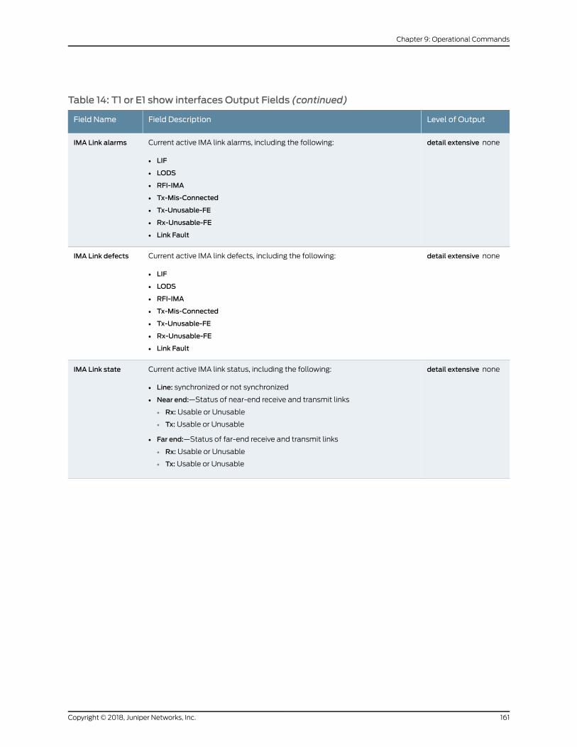
Table 14: T1 or E1 show interfaces Output Fields (continued)
Level of OutputField DescriptionField Name
detail extensive noneCurrent active IMA link alarms, including the following:
• LIF
• LODS
• RFI-IMA
• Tx-Mis-Connected
• Tx-Unusable-FE
• Rx-Unusable-FE
• Link Fault
IMA Link alarms
detail extensive noneCurrent active IMA link defects, including the following:
• LIF
• LODS
• RFI-IMA
• Tx-Mis-Connected
• Tx-Unusable-FE
• Rx-Unusable-FE
• Link Fault
IMA Link defects
detail extensive noneCurrent active IMA link status, including the following:
• Line: synchronized or not synchronized
• Near end:—Status of near-end receive and transmit links
• Rx: Usable or Unusable
• Tx: Usable or Unusable
• Far end:—Status of far-end receive and transmit links
• Rx: Usable or Unusable
• Tx: Usable or Unusable
IMA Link state
161Copyright © 2018, Juniper Networks, Inc.
Chapter 9: Operational Commands

Table 14: T1 or E1 show interfaces Output Fields (continued)
Level of OutputField DescriptionField Name
detail extensive noneIMA Link Media Status, which provides the seconds and count state for thefollowing link media parameters:
• LIF
• LODS
• Err-ICP
• IV
• Rx-FC
• Tx-FC
• FE-Defects
• FE-Rx-FC
• FE-Tx-FC
• Rx-ICP
• Rx-Stuff
• Tx-ICP
• Tx-Stuff
• Rx-SES
• Rx-UAS
• Rx-UUS
• Tx-UUS
• FE-Rx-SES
• FE-Rx-UAS
• FE-Rx-UUS
• FE-Tx-UUS
IMA linkmedia
detail extensive none(PPP and HDLC) Configured settings for keepalives.
• intervalseconds—The time in secondsbetweensuccessive keepalive requests.The range is 10 seconds through 32,767 seconds,with adefault of 10 seconds.
• down-count number—The number of keepalive packets a destination mustfail to receive before the network takes a link down. The range is 1 through255, with a default of 3.
• up-countnumber—Thenumberofkeepalivepacketsadestinationmust receiveto change a link’s status from down to up. The range is 1 through 255, with adefault of 1.
Keepalive settings
detail extensive none(PPPandHDLC) Informationabout keepalivepackets. (Whenno level of outputis specified, the word statistics is not part of the field name and the last seentext is not displayed.)
• Input—Number of keepalive packets received by PPP.
• (last seen 00:00:00 ago)—Time since the last keepalive packet wasreceived, in the format hh:mm:ss.
• Output—Number of keepalive packets sent byPPPandhow longago the lastkeepalive packets were sent and received.
• (last seen 00:00:00 ago)—Time since the last keepalive packet was sent,in the format hh:mm:ss.
Keepalive statistics
Copyright © 2018, Juniper Networks, Inc.162
Circuit Emulation Interfaces Feature Guide for Routing Devices
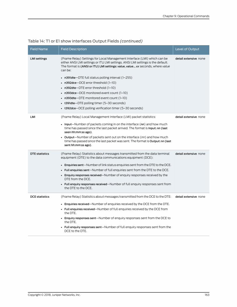
Table 14: T1 or E1 show interfaces Output Fields (continued)
Level of OutputField DescriptionField Name
detail extensive none(Frame Relay) Settings for Local Management Interface (LMI) which can beeither ANSI LMI settings or ITU LMI settings. ANSI LMI settings is the default.The format is (ANSI or ITU) LMI settings: value, value... xx seconds, where valuecan be:
• n391dte—DTE full status polling interval (1–255)
• n392dce—DCE error threshold (1–10)
• n392dte—DTE error threshold (1–10)
• n393dce—DCEmonitored event count (1–10)
• n393dte—DTEmonitored event count (1–10)
• t391dte—DTE polling timer (5–30 seconds)
• t392dce—DCE polling verification timer (5–30 seconds)
LMI settings
detail extensive none(Frame Relay) Local Management Interface (LMI) packet statistics:
• Input—Number of packets coming in on the interface (nn) and howmuchtime has passed since the last packet arrived. The format is Input: nn (lastseen hh:mm:ss ago).
• Output—Number of packets sent out on the interface (nn) and howmuchtimehas passed since the last packetwas sent. The format isOutput:nn (lastsent hh:mm:ss ago).
LMI
detail extensive none(Frame Relay) Statistics about messages transmitted from the data terminalequipment (DTE) to the data communications equipment (DCE):
• Enquiries sent—Number of link status enquiries sent from theDTE to theDCE.
• Full enquiries sent—Number of full enquiries sent from the DTE to the DCE.
• Enquiry responses received—Number of enquiry responses received by theDTE from the DCE.
• Full enquiry responses received—Number of full enquiry responses sent fromthe DTE to the DCE.
DTE statistics
detail extensive none(FrameRelay) Statistics aboutmessages transmitted from theDCE to theDTE:
• Enquiries received—Number of enquiries received by the DCE from the DTE.
• Full enquiries received—Number of full enquiries received by the DCE fromthe DTE.
• Enquiry responses sent—Number of enquiry responses sent from the DCE tothe DTE.
• Full enquiry responses sent—Number of full enquiry responses sent from theDCE to the DTE.
DCE statistics
163Copyright © 2018, Juniper Networks, Inc.
Chapter 9: Operational Commands

Table 14: T1 or E1 show interfaces Output Fields (continued)
Level of OutputField DescriptionField Name
detail extensive none(Frame Relay) Statistics about messages sent between the DTE and the DCE:
• Unknownmessages received—Number of received packets that do not fallinto any category.
• Asynchronousupdates received—Numberof link statuspeer changes received.
• Out-of-sequencepacketsreceived—Numberofpackets forwhich thesequenceof the packets received is different from the expected sequence.
• Keepalive responses timedout—Number of keepalive responses that timedout when no Local Management Interface (LMI) packet was reported forn392dte or n393dce intervals. (See LMI settings.)
Common statistics
detail extensive none(Frame Relay. Displayed only from the DTE.) Number of DLCIs configured fromthe DCE.
NonmatchingDCE-end DLCIs
detail extensive none(PPP) Link Control Protocol state.
• Conf-ack-received—Acknowledgement was received.
• Conf-ack-sent—Acknowledgement was sent.
• Conf-req-sent—Request was sent.
• Down—LCP negotiation is incomplete (not yet completed or has failed).
• Not configured—LCP is not configured on the interface.
• Opened—LCP negotiation is successful.
LCP state
detail extensive none(PPP) Network Control Protocol state.
• Conf-ack-received—Acknowledgement was received.
• Conf-ack-sent—Acknowledgement was sent.
• Conf-req-sent—Request was sent.
• Down—NCP negotiation is incomplete (not yet completed or has failed).
• Not configured—NCP is not configured on the interface.
• Opened—NCP negotiation is successful.
NCP state
detail extensive none(PPP) State of the Challenge Handshake Authentication Protocol (CHAP)during its transaction.
• Chap-Chal-received—Challenge was received but response is not yet sent.
• Chap-Chal-sent—Challenge was sent.
• Chap-Resp-received—Response was received for the challenge sent, butCHAP has not yet moved into the Success state. (Most likely with RADIUSauthentication.)
• Chap-Resp-sent—Response was sent for the challenge received.
• Down—CHAPauthentication is incomplete (not yet completedor has failed).
• Not-configured—CHAP is not configured on the interface.
• Opened—CHAP authentication was successful.
CHAP state
detail extensive noneDate, time, and how long ago the interface went from down to up. The formatisLast flapped:year-month-dayhour:minute:secondtimezone (hour:minute:secondago). For example, Last flapped: 2002-04-26 10:52:40 PDT (04:33:20 ago).
Last flapped
Copyright © 2018, Juniper Networks, Inc.164
Circuit Emulation Interfaces Feature Guide for Routing Devices
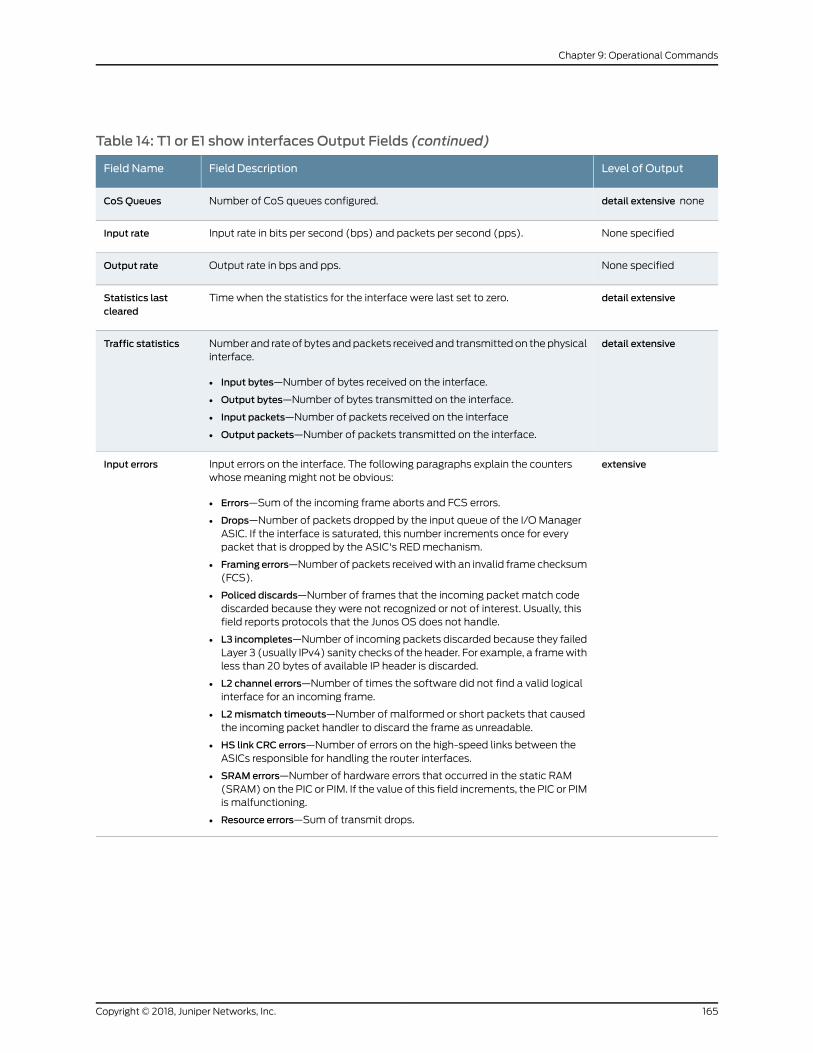
Table 14: T1 or E1 show interfaces Output Fields (continued)
Level of OutputField DescriptionField Name
detail extensive noneNumber of CoS queues configured.CoSQueues
None specifiedInput rate in bits per second (bps) and packets per second (pps).Input rate
None specifiedOutput rate in bps and pps.Output rate
detail extensiveTime when the statistics for the interface were last set to zero.Statistics lastcleared
detail extensiveNumber and rate of bytes andpackets receivedand transmittedon thephysicalinterface.
• Input bytes—Number of bytes received on the interface.
• Output bytes—Number of bytes transmitted on the interface.
• Input packets—Number of packets received on the interface
• Output packets—Number of packets transmitted on the interface.
Traffic statistics
extensiveInput errors on the interface. The following paragraphs explain the counterswhosemeaning might not be obvious:
• Errors—Sum of the incoming frame aborts and FCS errors.
• Drops—Number of packets dropped by the input queue of the I/O ManagerASIC. If the interface is saturated, this number increments once for everypacket that is dropped by the ASIC's REDmechanism.
• Framing errors—Number of packets receivedwith an invalid frame checksum(FCS).
• Policed discards—Number of frames that the incoming packet match codediscarded because they were not recognized or not of interest. Usually, thisfield reports protocols that the Junos OS does not handle.
• L3 incompletes—Number of incoming packets discarded because they failedLayer 3 (usually IPv4) sanity checks of the header. For example, a framewithless than 20 bytes of available IP header is discarded.
• L2 channel errors—Number of times the software did not find a valid logicalinterface for an incoming frame.
• L2mismatch timeouts—Number of malformed or short packets that causedthe incoming packet handler to discard the frame as unreadable.
• HS link CRC errors—Number of errors on the high-speed links between theASICs responsible for handling the router interfaces.
• SRAM errors—Number of hardware errors that occurred in the static RAM(SRAM) on the PIC or PIM. If the value of this field increments, the PIC or PIMis malfunctioning.
• Resource errors—Sum of transmit drops.
Input errors
165Copyright © 2018, Juniper Networks, Inc.
Chapter 9: Operational Commands

Table 14: T1 or E1 show interfaces Output Fields (continued)
Level of OutputField DescriptionField Name
extensiveOutput errors on the interface. The following paragraphs explain the counterswhosemeaning might not be obvious:
• Carrier transitions—Number of times the interface has gone from down to up.This number does not normally increment quickly, increasing only when thecable is unplugged, the far-end system is powered down and up, or anotherproblem occurs. If the number of carrier transitions increments quickly(perhaps once every 10 seconds), the cable, the far-end system, or the PICor PIM is malfunctioning.
• Errors—Sum of the outgoing frame aborts and FCS errors.
• Drops—Number of packets dropped by the output queue of the I/OManagerASIC. If the interface is saturated, this number increments once for everypacket that is dropped by the ASIC's REDmechanism.
• Aged packets—Number of packets that remained in shared packet SDRAMso long that the system automatically purged them. The value in this fieldshould never increment. If it does, it is most likely a software bug or possiblymalfunctioning hardware.
• MTUerrors—NumberofpacketswhosesizeexceededtheMTUof the interface.
• Resource errors—Sum of transmit drops.
Output errors
detail extensiveCoS queue number and its associated user-configured forwarding class name.
• Queued packets—Number of queued packets.
• Transmitted packets—Number of transmitted packets.
• Droppedpackets—Numberofpacketsdroppedby theASIC'sREDmechanism.
Queue counters
detail extensive noneE1 media-specific defects that can prevent the interface from passing packets.When a defect persists for a certain amount of time, it is promoted to an alarm.Based on the router configuration, an alarm can ring the red or yellow alarmbell on the router, or turn on the red or yellow alarm LED on the craft interface.The following lists all possible alarms and defects. For complete explanationsof most of these alarms and defects, see Bellcore Telcordia GR-499-CORE.
• AIS—Alarm indication signal.
• LOF—Loss of frame.
• LOS—Loss of signal.
• YLW—Yellow alarm. Indicates errors at the remote site receiver.
DS1 alarms
DS1 defects
Copyright © 2018, Juniper Networks, Inc.166
Circuit Emulation Interfaces Feature Guide for Routing Devices
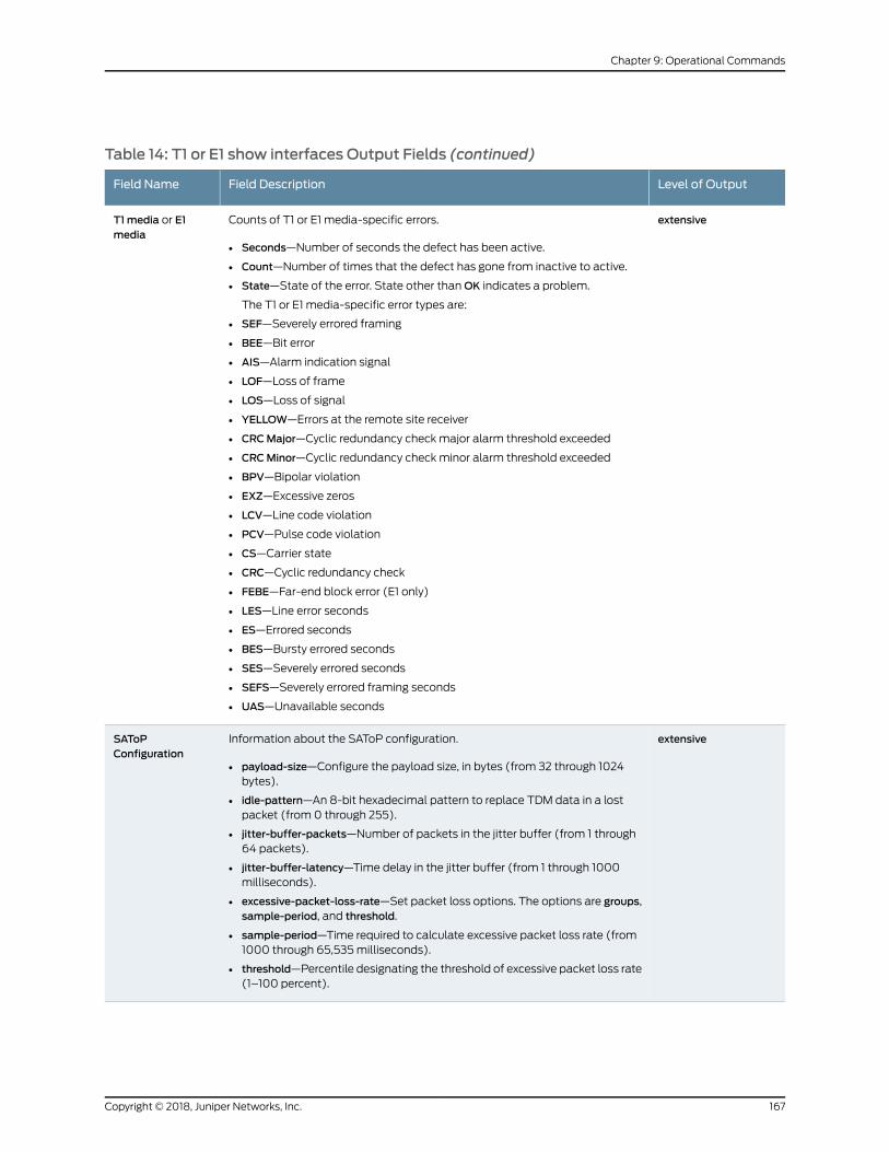
Table 14: T1 or E1 show interfaces Output Fields (continued)
Level of OutputField DescriptionField Name
extensiveCounts of T1 or E1 media-specific errors.
• Seconds—Number of seconds the defect has been active.
• Count—Number of times that the defect has gone from inactive to active.
• State—State of the error. State other thanOK indicates a problem.
The T1 or E1 media-specific error types are:
• SEF—Severely errored framing
• BEE—Bit error
• AIS—Alarm indication signal
• LOF—Loss of frame
• LOS—Loss of signal
• YELLOW—Errors at the remote site receiver
• CRCMajor—Cyclic redundancy check major alarm threshold exceeded
• CRCMinor—Cyclic redundancy check minor alarm threshold exceeded
• BPV—Bipolar violation
• EXZ—Excessive zeros
• LCV—Line code violation
• PCV—Pulse code violation
• CS—Carrier state
• CRC—Cyclic redundancy check
• FEBE—Far-end block error (E1 only)
• LES—Line error seconds
• ES—Errored seconds
• BES—Bursty errored seconds
• SES—Severely errored seconds
• SEFS—Severely errored framing seconds
• UAS—Unavailable seconds
T1media or E1media
extensiveInformation about the SAToP configuration.
• payload-size—Configure the payload size, in bytes (from 32 through 1024bytes).
• idle-pattern—An 8-bit hexadecimal pattern to replace TDM data in a lostpacket (from 0 through 255).
• jitter-buffer-packets—Number of packets in the jitter buffer (from 1 through64 packets).
• jitter-buffer-latency—Time delay in the jitter buffer (from 1 through 1000milliseconds).
• excessive-packet-loss-rate—Set packet loss options. The options are groups,sample-period, and threshold.
• sample-period—Time required to calculate excessive packet loss rate (from1000 through 65,535milliseconds).
• threshold—Percentile designating the threshold of excessive packet loss rate(1–100 percent).
SAToPConfiguration
167Copyright © 2018, Juniper Networks, Inc.
Chapter 9: Operational Commands
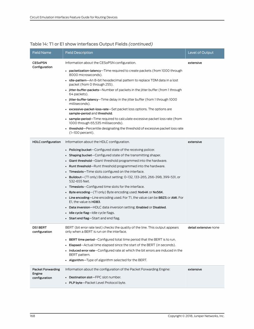
Table 14: T1 or E1 show interfaces Output Fields (continued)
Level of OutputField DescriptionField Name
extensiveInformation about the CESoPSN configuration.
• packetization-latency—Time required to create packets (from 1000 through8000microseconds).
• idle-pattern—An 8-bit hexadecimal pattern to replace TDM data in a lostpacket (from 0 through 255).
• jitter-buffer-packets—Number of packets in the jitter buffer (from 1 through64 packets).
• jitter-buffer-latency—Time delay in the jitter buffer (from 1 through 1000milliseconds).
• excessive-packet-loss-rate—Set packet loss options. The options aresample-period and threshold.
• sample-period—Time required to calculate excessive packet loss rate (from1000 through 65,535milliseconds).
• threshold—Percentile designating the threshold of excessive packet loss rate(1–100 percent).
CESoPSNConfiguration
extensiveInformation about the HDLC configuration.
• Policing bucket—Configured state of the receiving policer.
• Shaping bucket—Configured state of the transmitting shaper.
• Giant threshold—Giant threshold programmed into the hardware.
• Runt threshold—Runt threshold programmed into the hardware.
• Timeslots—Time slots configured on the interface.
• Buildout—(T1 only) Buildout setting: 0-132, 133-265, 266-398, 399-531, or532-655 feet.
• Timeslots—Configured time slots for the interface.
• Byte encoding—(T1 only) Byte encoding used: Nx64K or Nx56K.
• Line encoding—Line encoding used. For T1, the value can be B8ZS or AMI. ForE1, the value is HDB3.
• Data inversion—HDLC data inversion setting: Enabled or Disabled.
• Idle cycle flag—Idle cycle flags.
• Start end flag—Start and end flag.
HDLCconfiguration
detail extensive noneBERT (bit error rate test) checks the quality of the line. This output appearsonly when a BERT is run on the interface.
• BERT time period—Configured total time period that the BERT is to run.
• Elapsed—Actual time elapsed since the start of the BERT (in seconds).
• Induced error rate—Configured rate at which the bit errors are induced in theBERT pattern.
• Algorithm—Type of algorithm selected for the BERT.
DS1 BERTconfiguration
extensiveInformation about the configuration of the Packet Forwarding Engine:
• Destination slot—FPC slot number.
• PLP byte—Packet Level Protocol byte.
Packet ForwardingEngineconfiguration
Copyright © 2018, Juniper Networks, Inc.168
Circuit Emulation Interfaces Feature Guide for Routing Devices
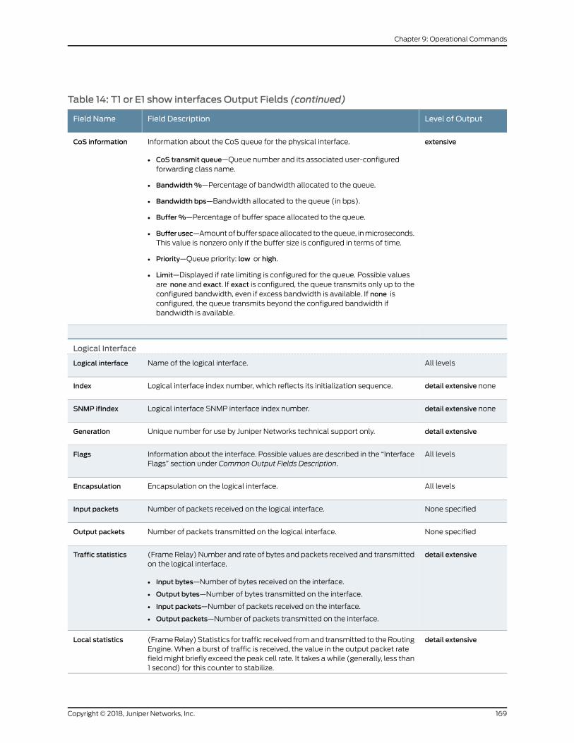
Table 14: T1 or E1 show interfaces Output Fields (continued)
Level of OutputField DescriptionField Name
extensiveInformation about the CoS queue for the physical interface.
• CoS transmit queue—Queue number and its associated user-configuredforwarding class name.
• Bandwidth%—Percentage of bandwidth allocated to the queue.
• Bandwidth bps—Bandwidth allocated to the queue (in bps).
• Buffer%—Percentage of buffer space allocated to the queue.
• Bufferusec—Amountofbuffer spaceallocated to thequeue, inmicroseconds.This value is nonzero only if the buffer size is configured in terms of time.
• Priority—Queue priority: low or high.
• Limit—Displayed if rate limiting is configured for the queue. Possible valuesare none and exact. If exact is configured, the queue transmits only up to theconfigured bandwidth, even if excess bandwidth is available. If none isconfigured, the queue transmits beyond the configured bandwidth ifbandwidth is available.
CoS information
Logical Interface
All levelsName of the logical interface.Logical interface
detail extensive noneLogical interface index number, which reflects its initialization sequence.Index
detail extensive noneLogical interface SNMP interface index number.SNMP ifIndex
detail extensiveUnique number for use by Juniper Networks technical support only.Generation
All levelsInformation about the interface. Possible values are described in the “InterfaceFlags” section under Common Output Fields Description.
Flags
All levelsEncapsulation on the logical interface.Encapsulation
None specifiedNumber of packets received on the logical interface.Input packets
None specifiedNumber of packets transmitted on the logical interface.Output packets
detail extensive(FrameRelay) Number and rate of bytes and packets received and transmittedon the logical interface.
• Input bytes—Number of bytes received on the interface.
• Output bytes—Number of bytes transmitted on the interface.
• Input packets—Number of packets received on the interface.
• Output packets—Number of packets transmitted on the interface.
Traffic statistics
detail extensive(FrameRelay)Statistics for traffic received fromand transmitted to theRoutingEngine. When a burst of traffic is received, the value in the output packet ratefieldmight briefly exceed the peak cell rate. It takes awhile (generally, less than1 second) for this counter to stabilize.
Local statistics
169Copyright © 2018, Juniper Networks, Inc.
Chapter 9: Operational Commands

Table 14: T1 or E1 show interfaces Output Fields (continued)
Level of OutputField DescriptionField Name
detail extensive(Frame Relay) Statistics for traffic transiting the router. When a burst of trafficis received, the value in the output packet rate field might briefly exceed thepeak cell rate. This counter normally stabilizes in less than 1 second.
Transit statistics
detail extensive noneProtocol family configured on the logical interface, such as iso, inet6,mlfr, ormpls.
Protocol
detail extensive noneInterface name for the multilink bundle, if configured.Multilink bundle
detail extensive noneMTU size on the logical interface.MTU
detail extensiveUnique number for use by Juniper Networks technical support only.Generation
detail extensiveRouting table in which the logical interface address is located. For example, 0refers to the routing table inet.0.
Route table
detail extensive noneInformation about the protocol family flags. Possible values are described inthe “Family Flags” section under Common Output Fields Description.
Flags
detail extensive noneInformation about the address flags. Possible values are described in the“Addresses Flags” section under Common Output Fields Description.
Addresses, Flags
detail extensive noneIP address of the remote side of the connection.Destination
detail extensive noneIP address of the logical interface.Local
detail extensive noneBroadcast address.Broadcast
detail extensive noneUnique number for use by Juniper Networks technical support only.Generation
detail extensive none(Frame Relay) DLCI number of the logical interface. The following DLCIinformation is displayed: Flags, Total down time, Last down, and Traffic statisticsor (Input packets, Output packets). Flags can be one or more of the following:
• Active—Set when the link is active and the DTE and DCE are exchanginginformation.
• Down—Set when the link is active, but no information is received from theDCE.
• DCE-Unconfigured—Set when the corresponding DLCI in the DCE is notconfigured.
• Configured—Set when the corresponding DLCI in the DCE is configured.
• DCE-configured—Displayed when the command is issued from the DTE.
DLCI
detail extensive none(Frame Relay) Data-link connection identifier (DLCI) statistics.
• Active DLCI—Number of active DLCIs.
• Inactive DLCI—Number of inactive DLCIs.
DLCI statistics
Copyright © 2018, Juniper Networks, Inc.170
Circuit Emulation Interfaces Feature Guide for Routing Devices
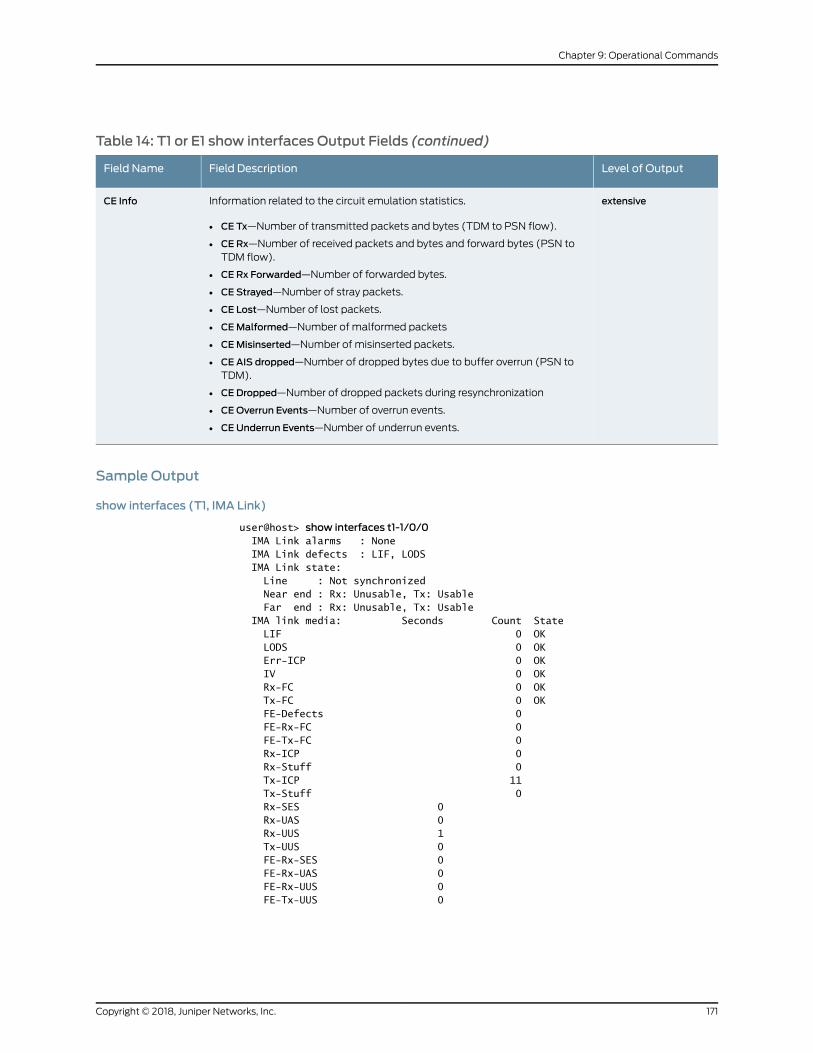
Table 14: T1 or E1 show interfaces Output Fields (continued)
Level of OutputField DescriptionField Name
extensiveInformation related to the circuit emulation statistics.
• CE Tx—Number of transmitted packets and bytes (TDM to PSN flow).
• CE Rx—Number of received packets and bytes and forward bytes (PSN toTDM flow).
• CE Rx Forwarded—Number of forwarded bytes.
• CE Strayed—Number of stray packets.
• CE Lost—Number of lost packets.
• CEMalformed—Number of malformed packets
• CEMisinserted—Number of misinserted packets.
• CE AIS dropped—Number of dropped bytes due to buffer overrun (PSN toTDM).
• CE Dropped—Number of dropped packets during resynchronization
• CEOverrun Events—Number of overrun events.
• CE Underrun Events—Number of underrun events.
CE Info
Sample Output
show interfaces (T1, IMA Link)
user@host> show interfaces t1-1/0/0 IMA Link alarms : None IMA Link defects : LIF, LODS IMA Link state: Line : Not synchronized Near end : Rx: Unusable, Tx: Usable Far end : Rx: Unusable, Tx: Usable IMA link media: Seconds Count State LIF 0 OK LODS 0 OK Err-ICP 0 OK IV 0 OK Rx-FC 0 OK Tx-FC 0 OK FE-Defects 0 FE-Rx-FC 0 FE-Tx-FC 0 Rx-ICP 0 Rx-Stuff 0 Tx-ICP 11 Tx-Stuff 0 Rx-SES 0 Rx-UAS 0 Rx-UUS 1 Tx-UUS 0 FE-Rx-SES 0 FE-Rx-UAS 0 FE-Rx-UUS 0 FE-Tx-UUS 0
171Copyright © 2018, Juniper Networks, Inc.
Chapter 9: Operational Commands

show interfaces (T1, PPP)
user@host> show interfaces t1-1/1/0Physical interface: t1-1/1/0, Enabled, Physical link is Up Interface index: 149, SNMP ifIndex: 45 Link-level type: PPP, MTU: 1504, Clocking: Internal, Speed: T1, Loopback: None, FCS: 16, Framing: ESF Device flags : Present Running Interface flags: Point-To-Point SNMP-Traps Internal: 0x4000 Link flags : Keepalives Keepalive settings: Interval 10 seconds, Up-count 1, Down-count 3 Keepalive: Input: 0 (never), Output: 0 (never) LCP state: Opened NCP state: Opened CHAP state: Opened CoS queues : 4 supported, 4 in use Last flapped : 2005-12-05 08:43:06 PST (02:13:35 ago) Input rate : 0 bps (0 pps) Output rate : 72 bps (0 pps) DS1 alarms : None DS1 defects : None
Logical interface t1-1/1/0.0 (Index 66) (SNMP ifIndex 51) Flags: Hardware-Down Point-To-Point SNMP-Traps Encapsulation: PPP Protocol inet, MTU: 1500 Flags: Protocol-Down Addresses, Flags: Dest-route-down Is-Preferred Is-Primary Destination: 198.51.100.0/24, Local: 198.51.100.1, Broadcast: 198.51.100.255
show interfaces detail (T1, PPP)
user@host> show interfaces t1-1/1/0 detailPhysical interface: t1-1/1/0, Enabled, Physical link is Up Interface index: 149, SNMP ifIndex: 45, Generation: 32 Link-level type: PPP, MTU: 1504, Clocking: Internal, Speed: T1, Loopback: None, FCS: 16, Framing: ESF Device flags : Present Running Interface flags: Point-To-Point SNMP-Traps Internal: 0x4000 Link flags : Keepalives Hold-times : Up 0 ms, Down 0 ms Keepalive settings: Interval 10 seconds, Up-count 1, Down-count 3 Keepalive statistics: Input : 0 (last seen: never) Output: 0 (last sent: never) LCP state: Opened NCP state: Opened CHAP state: Opened CoS queues : 4 supported, 4 in use Last flapped : 2005-12-05 08:43:06 PST (02:13:52 ago) Statistics last cleared: Never Traffic statistics: Input bytes : 0 0 bps Output bytes : 798 0 bps Input packets: 0 0 pps Output packets: 42 0 pps Queue counters: Queued packets Transmitted packets Dropped packets
0 best-effort 0 0 0
Copyright © 2018, Juniper Networks, Inc.172
Circuit Emulation Interfaces Feature Guide for Routing Devices
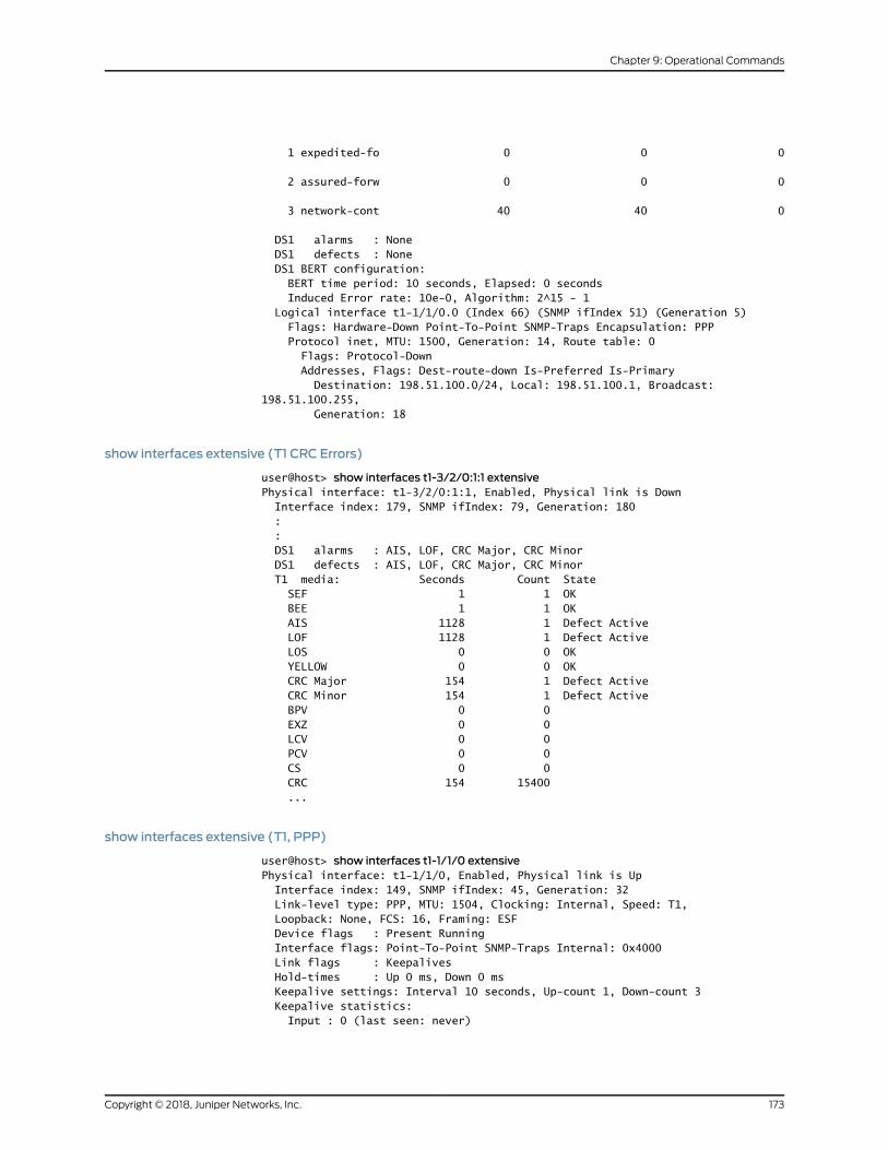
1 expedited-fo 0 0 0
2 assured-forw 0 0 0
3 network-cont 40 40 0
DS1 alarms : None DS1 defects : None DS1 BERT configuration: BERT time period: 10 seconds, Elapsed: 0 seconds Induced Error rate: 10e-0, Algorithm: 2^15 - 1 Logical interface t1-1/1/0.0 (Index 66) (SNMP ifIndex 51) (Generation 5) Flags: Hardware-Down Point-To-Point SNMP-Traps Encapsulation: PPP Protocol inet, MTU: 1500, Generation: 14, Route table: 0 Flags: Protocol-Down Addresses, Flags: Dest-route-down Is-Preferred Is-Primary Destination: 198.51.100.0/24, Local: 198.51.100.1, Broadcast: 198.51.100.255, Generation: 18
show interfaces extensive (T1 CRC Errors)
user@host> show interfaces t1-3/2/0:1:1 extensivePhysical interface: t1-3/2/0:1:1, Enabled, Physical link is Down Interface index: 179, SNMP ifIndex: 79, Generation: 180 : : DS1 alarms : AIS, LOF, CRC Major, CRC Minor DS1 defects : AIS, LOF, CRC Major, CRC Minor T1 media: Seconds Count State SEF 1 1 OK BEE 1 1 OK AIS 1128 1 Defect Active LOF 1128 1 Defect Active LOS 0 0 OK YELLOW 0 0 OK CRC Major 154 1 Defect Active CRC Minor 154 1 Defect Active BPV 0 0 EXZ 0 0 LCV 0 0 PCV 0 0 CS 0 0 CRC 154 15400 ...
show interfaces extensive (T1, PPP)
user@host> show interfaces t1-1/1/0 extensivePhysical interface: t1-1/1/0, Enabled, Physical link is Up Interface index: 149, SNMP ifIndex: 45, Generation: 32 Link-level type: PPP, MTU: 1504, Clocking: Internal, Speed: T1, Loopback: None, FCS: 16, Framing: ESF Device flags : Present Running Interface flags: Point-To-Point SNMP-Traps Internal: 0x4000 Link flags : Keepalives Hold-times : Up 0 ms, Down 0 ms Keepalive settings: Interval 10 seconds, Up-count 1, Down-count 3 Keepalive statistics: Input : 0 (last seen: never)
173Copyright © 2018, Juniper Networks, Inc.
Chapter 9: Operational Commands
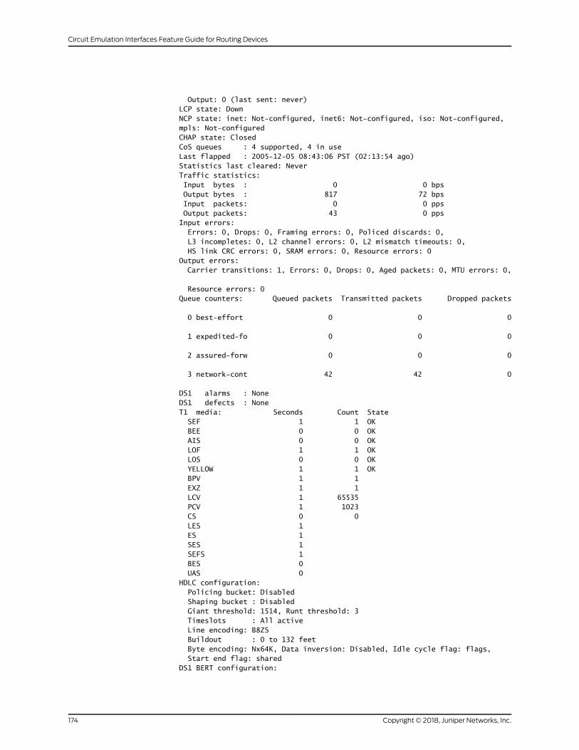
Output: 0 (last sent: never) LCP state: Down NCP state: inet: Not-configured, inet6: Not-configured, iso: Not-configured, mpls: Not-configured CHAP state: Closed CoS queues : 4 supported, 4 in use Last flapped : 2005-12-05 08:43:06 PST (02:13:54 ago) Statistics last cleared: Never Traffic statistics: Input bytes : 0 0 bps Output bytes : 817 72 bps Input packets: 0 0 pps Output packets: 43 0 pps Input errors: Errors: 0, Drops: 0, Framing errors: 0, Policed discards: 0, L3 incompletes: 0, L2 channel errors: 0, L2 mismatch timeouts: 0, HS link CRC errors: 0, SRAM errors: 0, Resource errors: 0 Output errors: Carrier transitions: 1, Errors: 0, Drops: 0, Aged packets: 0, MTU errors: 0,
Resource errors: 0 Queue counters: Queued packets Transmitted packets Dropped packets
0 best-effort 0 0 0
1 expedited-fo 0 0 0
2 assured-forw 0 0 0
3 network-cont 42 42 0
DS1 alarms : None DS1 defects : None T1 media: Seconds Count State SEF 1 1 OK BEE 0 0 OK AIS 0 0 OK LOF 1 1 OK LOS 0 0 OK YELLOW 1 1 OK BPV 1 1 EXZ 1 1 LCV 1 65535 PCV 1 1023 CS 0 0 LES 1 ES 1 SES 1 SEFS 1 BES 0 UAS 0 HDLC configuration: Policing bucket: Disabled Shaping bucket : Disabled Giant threshold: 1514, Runt threshold: 3 Timeslots : All active Line encoding: B8ZS Buildout : 0 to 132 feet Byte encoding: Nx64K, Data inversion: Disabled, Idle cycle flag: flags, Start end flag: shared DS1 BERT configuration:
Copyright © 2018, Juniper Networks, Inc.174
Circuit Emulation Interfaces Feature Guide for Routing Devices
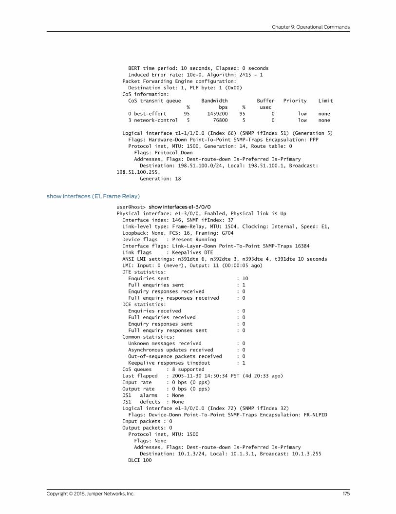
BERT time period: 10 seconds, Elapsed: 0 seconds Induced Error rate: 10e-0, Algorithm: 2^15 - 1 Packet Forwarding Engine configuration: Destination slot: 1, PLP byte: 1 (0x00) CoS information: CoS transmit queue Bandwidth Buffer Priority Limit % bps % usec 0 best-effort 95 1459200 95 0 low none 3 network-control 5 76800 5 0 low none
Logical interface t1-1/1/0.0 (Index 66) (SNMP ifIndex 51) (Generation 5) Flags: Hardware-Down Point-To-Point SNMP-Traps Encapsulation: PPP Protocol inet, MTU: 1500, Generation: 14, Route table: 0 Flags: Protocol-Down Addresses, Flags: Dest-route-down Is-Preferred Is-Primary Destination: 198.51.100.0/24, Local: 198.51.100.1, Broadcast: 198.51.100.255, Generation: 18
show interfaces (E1, Frame Relay)
user@host> show interfaces e1-3/0/0Physical interface: e1-3/0/0, Enabled, Physical link is Up Interface index: 146, SNMP ifIndex: 37 Link-level type: Frame-Relay, MTU: 1504, Clocking: Internal, Speed: E1, Loopback: None, FCS: 16, Framing: G704 Device flags : Present Running Interface flags: Link-Layer-Down Point-To-Point SNMP-Traps 16384 Link flags : Keepalives DTE ANSI LMI settings: n391dte 6, n392dte 3, n393dte 4, t391dte 10 seconds LMI: Input: 0 (never), Output: 11 (00:00:05 ago) DTE statistics: Enquiries sent : 10 Full enquiries sent : 1 Enquiry responses received : 0 Full enquiry responses received : 0 DCE statistics: Enquiries received : 0 Full enquiries received : 0 Enquiry responses sent : 0 Full enquiry responses sent : 0 Common statistics: Unknown messages received : 0 Asynchronous updates received : 0 Out-of-sequence packets received : 0 Keepalive responses timedout : 1 CoS queues : 8 supported Last flapped : 2005-11-30 14:50:34 PST (4d 20:33 ago) Input rate : 0 bps (0 pps) Output rate : 0 bps (0 pps) DS1 alarms : None DS1 defects : None Logical interface e1-3/0/0.0 (Index 72) (SNMP ifIndex 32) Flags: Device-Down Point-To-Point SNMP-Traps Encapsulation: FR-NLPID Input packets : 0 Output packets: 0 Protocol inet, MTU: 1500 Flags: None Addresses, Flags: Dest-route-down Is-Preferred Is-Primary Destination: 10.1.3/24, Local: 10.1.3.1, Broadcast: 10.1.3.255 DLCI 100
175Copyright © 2018, Juniper Networks, Inc.
Chapter 9: Operational Commands
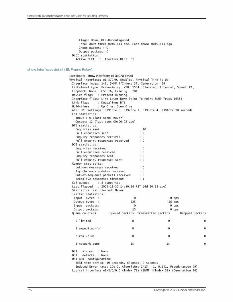
Flags: Down, DCE-Unconfigured Total down time: 00:01:13 sec, Last down: 00:01:13 ago Input packets : 0 Output packets: 0 DLCI statistics: Active DLCI :0 Inactive DLCI :1
show interfaces detail (E1, Frame Relay)
user@host> show interfaces e1-3/0/0 detailPhysical interface: e1-3/0/0, Enabled, Physical link is Up Interface index: 146, SNMP ifIndex: 37, Generation: 69 Link-level type: Frame-Relay, MTU: 1504, Clocking: Internal, Speed: E1, Loopback: None, FCS: 16, Framing: G704 Device flags : Present Running Interface flags: Link-Layer-Down Point-To-Point SNMP-Traps 16384 Link flags : Keepalives DTE Hold-times : Up 0 ms, Down 0 ms ANSI LMI settings: n391dte 6, n392dte 3, n393dte 4, t391dte 10 seconds LMI statistics: Input : 0 (last seen: never) Output: 12 (last sent 00:00:02 ago) DTE statistics: Enquiries sent : 10 Full enquiries sent : 2 Enquiry responses received : 0 Full enquiry responses received : 0 DCE statistics: Enquiries received : 0 Full enquiries received : 0 Enquiry responses sent : 0 Full enquiry responses sent : 0 Common statistics: Unknown messages received : 0 Asynchronous updates received : 0 Out-of-sequence packets received : 0 Keepalive responses timedout : 1 CoS queues : 8 supported Last flapped : 2005-11-30 14:50:34 PST (4d 20:33 ago) Statistics last cleared: Never Traffic statistics: Input bytes : 0 0 bps Output bytes : 225 56 bps Input packets: 0 0 pps Output packets: 15 0 pps Queue counters: Queued packets Transmitted packets Dropped packets
0 limited 0 0 0
1 expedited-fo 0 0 0
2 real-plus 0 0 0
3 network-cont 15 15 0
DS1 alarms : None DS1 defects : None DS1 BERT configuration: BERT time period: 10 seconds, Elapsed: 0 seconds Induced Error rate: 10e-0, Algorithm: 2^15 - 1, O.151, Pseudorandom (9) Logical interface e1-3/0/0.0 (Index 72) (SNMP ifIndex 32) (Generation 26)
Copyright © 2018, Juniper Networks, Inc.176
Circuit Emulation Interfaces Feature Guide for Routing Devices
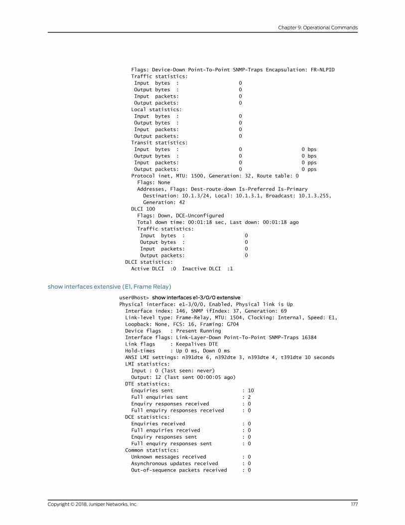
Flags: Device-Down Point-To-Point SNMP-Traps Encapsulation: FR-NLPID Traffic statistics: Input bytes : 0 Output bytes : 0 Input packets: 0 Output packets: 0 Local statistics: Input bytes : 0 Output bytes : 0 Input packets: 0 Output packets: 0 Transit statistics: Input bytes : 0 0 bps Output bytes : 0 0 bps Input packets: 0 0 pps Output packets: 0 0 pps Protocol inet, MTU: 1500, Generation: 32, Route table: 0 Flags: None Addresses, Flags: Dest-route-down Is-Preferred Is-Primary Destination: 10.1.3/24, Local: 10.1.3.1, Broadcast: 10.1.3.255, Generation: 42 DLCI 100 Flags: Down, DCE-Unconfigured Total down time: 00:01:18 sec, Last down: 00:01:18 ago Traffic statistics: Input bytes : 0 Output bytes : 0 Input packets: 0 Output packets: 0 DLCI statistics: Active DLCI :0 Inactive DLCI :1
show interfaces extensive (E1, Frame Relay)
user@host> show interfaces e1-3/0/0 extensivePhysical interface: e1-3/0/0, Enabled, Physical link is Up Interface index: 146, SNMP ifIndex: 37, Generation: 69 Link-level type: Frame-Relay, MTU: 1504, Clocking: Internal, Speed: E1, Loopback: None, FCS: 16, Framing: G704 Device flags : Present Running Interface flags: Link-Layer-Down Point-To-Point SNMP-Traps 16384 Link flags : Keepalives DTE Hold-times : Up 0 ms, Down 0 ms ANSI LMI settings: n391dte 6, n392dte 3, n393dte 4, t391dte 10 seconds LMI statistics: Input : 0 (last seen: never) Output: 12 (last sent 00:00:05 ago) DTE statistics: Enquiries sent : 10 Full enquiries sent : 2 Enquiry responses received : 0 Full enquiry responses received : 0 DCE statistics: Enquiries received : 0 Full enquiries received : 0 Enquiry responses sent : 0 Full enquiry responses sent : 0 Common statistics: Unknown messages received : 0 Asynchronous updates received : 0 Out-of-sequence packets received : 0
177Copyright © 2018, Juniper Networks, Inc.
Chapter 9: Operational Commands
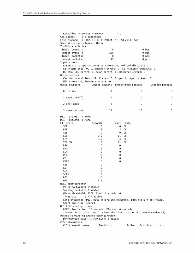
Keepalive responses timedout : 1 CoS queues : 8 supported Last flapped : 2005-11-30 14:50:34 PST (4d 20:33 ago) Statistics last cleared: Never Traffic statistics: Input bytes : 0 0 bps Output bytes : 225 0 bps Input packets: 0 0 pps Output packets: 15 0 pps Input errors: Errors: 0, Drops: 0, Framing errors: 0, Policed discards: 0, L3 incompletes: 0, L2 channel errors: 0, L2 mismatch timeouts: 0, HS link CRC errors: 0, SRAM errors: 0, Resource errors: 0 Output errors: Carrier transitions: 17, Errors: 0, Drops: 0, Aged packets: 0, MTU errors: 0, Resource errors: 0 Queue counters: Queued packets Transmitted packets Dropped packets
0 limited 0 0 0
1 expedited-fo 0 0 0
2 real-plus 0 0 0
3 network-cont 15 15 0
DS1 alarms : None DS1 defects : None E1 media: Seconds Count State SEF 0 0 OK BEE 5 5 OK AIS 0 0 OK LOF 245 15 OK LOS 245 4 OK YELLOW 0 11 OK BPV 0 0 EXZ 9 9 LCV 0 0 PCV 0 0 CS 0 0 FEBE 0 0 LES 0 ES 0 SES 0 SEFS 0 BES 0 UAS 271 HDLC configuration: Policing bucket: Disabled Shaping bucket : Disabled Giant threshold: 1506, Runt threshold: 0 Timeslots : All active Line encoding: HDB3, Data inversion: Disabled, Idle cycle flag: flags, Start end flag: shared DS1 BERT configuration: BERT time period: 10 seconds, Elapsed: 0 seconds Induced Error rate: 10e-0, Algorithm: 2^15 - 1, O.151, Pseudorandom (9) Packet Forwarding Engine configuration: Destination slot: 3, PLP byte: 1 (0x00) CoS information: CoS transmit queue Bandwidth Buffer Priority Limit
Copyright © 2018, Juniper Networks, Inc.178
Circuit Emulation Interfaces Feature Guide for Routing Devices

% bps % usec 0 limited 95 1945600 95 0 low none 3 network-control 5 102400 5 0 low none Logical interface e1-3/0/0.0 (Index 72) (SNMP ifIndex 32) (Generation 26) Flags: Device-Down Point-To-Point SNMP-Traps Encapsulation: FR-NLPID Traffic statistics: Input bytes : 0 Output bytes : 0 Input packets: 0 Output packets: 0 Local statistics: Input bytes : 0 Output bytes : 0 Input packets: 0 Output packets: 0 Transit statistics: Input bytes : 0 0 bps Output bytes : 0 0 bps Input packets: 0 0 pps Output packets: 0 0 pps Protocol inet, MTU: 1500, Generation: 32, Route table: 0 Flags: None Addresses, Flags: Dest-route-down Is-Preferred Is-Primary Destination: 10.1.3/24, Local: 10.1.3.1, Broadcast: 10.1.3.255, Generation: 42 DLCI 100 Flags: Down, DCE-Unconfigured Total down time: 00:01:21 sec, Last down: 00:01:21 ago Traffic statistics: Input bytes : 0 Output bytes : 0 Input packets: 0 Output packets: 0 DLCI statistics: Active DLCI :0 Inactive DLCI :1
show interfaces (E1, IMA Link)
user@host> show interfaces e1-1/0/0 IMA Link alarms : None IMA Link defects : LIF, LODS IMA Link state: Line : Not synchronized Near end : Rx: Unusable, Tx: Usable Far end : Rx: Unusable, Tx: Usable IMA link media: Seconds Count State LIF 0 LODS 0 Err-ICP 0 IV 0 Rx-FC 0 Tx-FC 0 FE-Defects 0 FE-Rx-FC 0 FE-Tx-FC 0 Rx-ICP 0 Rx-Stuff 0 Tx-ICP 11 Tx-Stuff 0 Rx-SES 0 Rx-UAS 0
179Copyright © 2018, Juniper Networks, Inc.
Chapter 9: Operational Commands
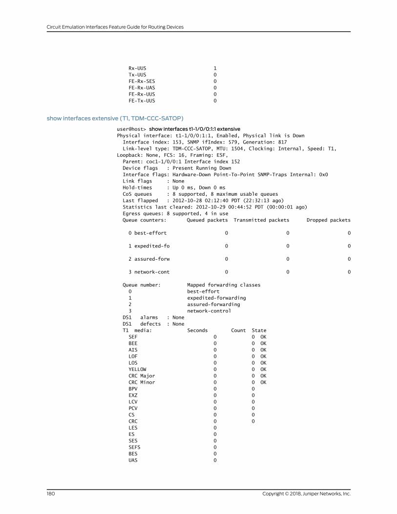
Rx-UUS 1 Tx-UUS 0 FE-Rx-SES 0 FE-Rx-UAS 0 FE-Rx-UUS 0 FE-Tx-UUS 0
show interfaces extensive (T1, TDM-CCC-SATOP)
user@host> show interfaces t1-1/0/0:1:1 extensivePhysical interface: t1-1/0/0:1:1, Enabled, Physical link is Down Interface index: 153, SNMP ifIndex: 579, Generation: 817 Link-level type: TDM-CCC-SATOP, MTU: 1504, Clocking: Internal, Speed: T1, Loopback: None, FCS: 16, Framing: ESF, Parent: coc1-1/0/0:1 Interface index 152 Device flags : Present Running Down Interface flags: Hardware-Down Point-To-Point SNMP-Traps Internal: 0x0 Link flags : None Hold-times : Up 0 ms, Down 0 ms CoS queues : 8 supported, 8 maximum usable queues Last flapped : 2012-10-28 02:12:40 PDT (22:32:13 ago) Statistics last cleared: 2012-10-29 00:44:52 PDT (00:00:01 ago) Egress queues: 8 supported, 4 in use Queue counters: Queued packets Transmitted packets Dropped packets
0 best-effort 0 0 0
1 expedited-fo 0 0 0
2 assured-forw 0 0 0
3 network-cont 0 0 0
Queue number: Mapped forwarding classes 0 best-effort 1 expedited-forwarding 2 assured-forwarding 3 network-control DS1 alarms : None DS1 defects : None T1 media: Seconds Count State SEF 0 0 OK BEE 0 0 OK AIS 0 0 OK LOF 0 0 OK LOS 0 0 OK YELLOW 0 0 OK CRC Major 0 0 OK CRC Minor 0 0 OK BPV 0 0 EXZ 0 0 LCV 0 0 PCV 0 0 CS 0 0 CRC 0 0 LES 0 ES 0 SES 0 SEFS 0 BES 0 UAS 0
Copyright © 2018, Juniper Networks, Inc.180
Circuit Emulation Interfaces Feature Guide for Routing Devices
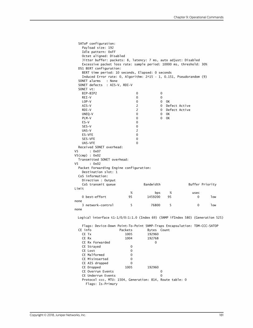
SAToP configuration: Payload size: 192 Idle pattern: 0xFF Octet aligned: Disabled Jitter buffer: packets: 8, latency: 7 ms, auto adjust: Disabled Excessive packet loss rate: sample period: 10000 ms, threshold: 30% DS1 BERT configuration: BERT time period: 10 seconds, Elapsed: 0 seconds Induced Error rate: 0, Algorithm: 2^15 - 1, O.151, Pseudorandom (9) SONET alarms : None SONET defects : AIS-V, RDI-V SONET vt: BIP-BIP2 0 0 REI-V 0 0 LOP-V 0 0 OK AIS-V 2 0 Defect Active RDI-V 2 0 Defect Active UNEQ-V 0 0 OK PLM-V 0 0 OK ES-V 0 SES-V 0 UAS-V 2 ES-VFE 0 SES-VFE 0 UAS-VFE 0 Received SONET overhead: V5 : 0x07 V5(cmp) : 0x02 Transmitted SONET overhead: V5 : 0x02 Packet Forwarding Engine configuration: Destination slot: 1 CoS information: Direction : Output CoS transmit queue Bandwidth Buffer Priority Limit % bps % usec 0 best-effort 95 1459200 95 0 low none 3 network-control 5 76800 5 0 low none
Logical interface t1-1/0/0:1:1.0 (Index 69) (SNMP ifIndex 580) (Generation 525)
Flags: Device-Down Point-To-Point SNMP-Traps Encapsulation: TDM-CCC-SATOP CE info Packets Bytes Count CE Tx 1005 192960 CE Rx 1004 192768 CE Rx Forwarded 0 CE Strayed 0 CE Lost 0 CE Malformed 0 CE Misinserted 0 CE AIS dropped 0 CE Dropped 1005 192960 CE Overrun Events 0 CE Underrun Events 0 Protocol ccc, MTU: 1504, Generation: 814, Route table: 0 Flags: Is-Primary
181Copyright © 2018, Juniper Networks, Inc.
Chapter 9: Operational Commands

show interfaces extensive (DS, TDM-CCC-CESoPSN)
user@host> show interfaces ds-1/0/0:1:1:1 extensivePhysical interface: ds-1/0/0:1:1:1, Enabled, Physical link is Down Interface index: 154, SNMP ifIndex: 597, Generation: 819 Link-level type: TDM-CCC-CESoPSN, MTU: 1504, Speed: 1536kbps, Loopback: None, FCS: 16, Parent: ct1-1/0/0:1:1 Interface index 153 Device flags : Present Running Down Interface flags: Hardware-Down Point-To-Point SNMP-Traps Internal: 0x0 Link flags : None Hold-times : Up 0 ms, Down 0 ms CoS queues : 8 supported, 8 maximum usable queues Last flapped : 2012-10-29 00:49:03 PDT (00:00:35 ago) Statistics last cleared: Never Egress queues: 8 supported, 4 in use Queue counters: Queued packets Transmitted packets Dropped packets
0 best-effort 0 0 0
1 expedited-fo 0 0 0
2 assured-forw 0 0 0
3 network-cont 0 0 0
Queue number: Mapped forwarding classes 0 best-effort 1 expedited-forwarding 2 assured-forwarding 3 network-control CESoPSN configuration: Packetization latency: 1000 us Idle pattern: 0xFF Jitter buffer: packets: 8, latency: 8 ms, auto adjust: Disabled Excessive packet loss rate: sample period: 10000 ms, threshold: 30% DS0 BERT configuration: BERT time period: 10 seconds, Elapsed: 0 seconds Induced Error rate: 0, Algorithm: 2^15 - 1, O.151, Pseudorandom (9) Packet Forwarding Engine configuration: Destination slot: 1 CoS information: Direction : Output CoS transmit queue Bandwidth Buffer Priority Limit % bps % usec 0 best-effort 95 1459200 95 0 low none 3 network-control 5 76800 5 0 low none
Logical interface ds-1/0/0:1:1:1.0 (Index 69) (SNMP ifIndex 598) (Generation 549) Flags: Device-Down Point-To-Point SNMP-Traps Encapsulation: TDM-CCC-CESoPSN CE info Packets Bytes Count CE Tx 0 0 CE Rx 35712 6856704 CE Rx Forwarded 0 CE Strayed 0 CE Lost 0 CE Malformed 0 CE Misinserted 0
Copyright © 2018, Juniper Networks, Inc.182
Circuit Emulation Interfaces Feature Guide for Routing Devices

CE AIS dropped 0 CE Dropped 0 0 CE Overrun Events 0 CE Underrun Events 1 Protocol ccc, MTU: 1504, Generation: 857, Route table: 0 Flags: Is-Primary
183Copyright © 2018, Juniper Networks, Inc.
Chapter 9: Operational Commands
show interfaces extensive
Syntax show interfaces extensive
Release Information Command introduced before Junos OS Release 7.4.
Command introduced in Junos OS Release 12.1x48 for PTX Series Packet Transport
Routers.
Command introduced in Junos OS Release 17.2 for PT1000 and PTX10008 Packet
Transport Routers.
Description Display extensive information about all interfaces configured on the router.
Copyright © 2018, Juniper Networks, Inc.184
Circuit Emulation Interfaces Feature Guide for Routing Devices

NOTE:
• At some times, the cumulative byte counters displayed with the show
interfaces extensive command on the 10-Gigabit Ethernet MPCwith SFP+
is not always increasing and cumulative and does not give the correctresults. There is a time lag in collecting these statistics, during which thedisplaymight decrease or go from a nonzero number to zero. Eventually,the counter will display the correct result.
• When the show interfaces extensive command is executed on a router with
anMPCoraT4000Type5FPC, the Inputpacket rejectscounter of theFilter
statistics fieldalsodisplays statistics related to the followingpacket errors:
• Invalid VLAN range
• Tagged packet received on an untagged interface
• When the show interfaces extensive command is executed on an interface
that is configured on a T4000 Type 5 FPC, the IPv6 transit statistics field
displays:
• Total statistics (sum of transit and local statistics) at the physicalinterface level
• Transit statistics at the logical interface level
• When the show interfaces extensive command is executed on an aggregate
interface in a T1600 Core Router, the IPv6 Input bytes is displayed for an
aggregate interface. However, the IPv6 Input bytes is always zero on a
member linkofanaggregatedbundleevenwhenthere is IPv6transit trafficon themember link. This is because the logical interface index of theaggregate logical interface is updated but not the logical interface of themember links in the channel lookup table.
• TheOutput packets field under the Traffic statistics section in the output
of the show interfaces extensive command includes both IPv4 and IPv6
packets. For example, in a scenario in which both IPv4 and IPv6 packetsare beingmirrored on the same interface andwhen you deactivate an IPv4port-mirroring instance on the chassis, the output of the show interfaces
extensivecommandshowsavalue in theOutputpackets fieldof theTraffic
statistics section, which is the value of IPv6 packets that aremirrored andnot of the IPv4 packets. This behavior is expected.
• For IQ2PIC interfaces, theoutputof the showinterfacesextensivecommand
displays byte statistics that includes Layer 2 headers.
• If there are active OTN defects when an ISSU is performed, and the defectpersists after the upgrade completes, theOTNalarmcount is incrementedby 1. For example, if anOTNalarm is activewith a count of 1 and the defectremains after ISSU, the alarm count is incremented to 2. This behavior isexpected.
185Copyright © 2018, Juniper Networks, Inc.
Chapter 9: Operational Commands

Options This command has no options.
Required PrivilegeLevel
view
List of Sample Output show interfaces extensive (Circuit Emulation) on page 186show interfaces extensive (Fast Ethernet) on page 187show interfaces extensive (Gigabit Ethernet) on page 189show interfaces extensive (10-Gigabit Ethernet) on page 189show interfaces extensive (IQ2 and IQ2E) on page 191show interfaces extensive (100-Gigabit Ethernet Type 4 PICwith CFP) on page 194show interfaces extensive (PTX5000 Packet Transport Router) on page 196sshow interfaces extensive (PTX Routers) on page 199show interfaces extensive (PTX10008 Routers) on page 199show interfaces extensive (PTX1000 Routers) on page 204show interfaces extensive (MX Series Routers) on page 205show interfaces extensive (MX480 Router with MPC5E and 10-Gigabit Ethernet OTNInterface) on page 208showinterfacesextensive(MX480RouterwithMPC5Eand100-GigabitEthernetOTNInterface) on page 209show interfaces extensive ((MX960RouterwithMPC3Eand 100-Gigabit DWDMOTNMIC) on page 212show interfaces extensive (PTX3000 Router with 5-port 100-Gigabit DWDMOTNPIC) on page 215show interfaces extensive (MX2020 Router with MPC6E andOTNMIC) on page 217show interfaces extensive (MX2010 Router with MPC6E and 100-Gigabit EthernetOTN Interface) on page 220show interfaces extensive (MX2010 Router with MPC6E and 10-Gigabit EthernetInterface) on page 222show interfaces extensive (T4000 Routers with Type 5 FPCs) on page 224show interfaces extensive (Aggregated Ethernet) on page 225
Output Fields Formore information, see the output fields table for the particular interface type inwhich
you are interested. For information about destination class and source class statistics,
see the “Destination Class Field” section and the “Source Class Field” section under
Common Output Fields Description. For sample output for specific interfaces, see the
other topics in this collection.
Sample Output
show interfaces extensive (Circuit Emulation)
If a Circuit Emulation (CE) PIC is configured for SAToP pseudowire, then pseudowire
statistics are displayed in the CE information section of the show interface extensive
output. If SAToP pseudowire is not configured on the CE PIC, then all CE information
counters display 0 (zero).
user@host> show interface t1-0/0/0 extensivePhysical interface :t1-0/0/0, Enabled, Physical Link : Up Interface index:61441
Copyright © 2018, Juniper Networks, Inc.186
Circuit Emulation Interfaces Feature Guide for Routing Devices

Speed : 1.54 Mbps, Loopback: Disabled Operational state : Enabled, Encapsulation : Trans Encoding : b8zs, Framing : unframe, Build-out : 0-30 Inversion : enable, Clock source : master Description : Traffic statistics: T1 media: Seconds ES 1643 SES 1643
CE Info Packets Bytes CE Rx : 2395529 306627712 CE Tx : 2396259 306721152 CE Rx Drop: 0 0 CE Tx Drop: 0 0
CE Overrun Events: 0 CE Underrun Events: 0
Sample Output
show interfaces extensive (Fast Ethernet)
user@host> show interfaces fe-0/2/1 extensivePhysical interface: fe-0/2/0, Enabled, Physical link is Up Interface index: 129, SNMP ifIndex: 23, Generation: 130 Link-level type: Ethernet, MTU: 1514, Speed: 100mbps, Loopback: Disabled, Source filtering: Disabled, Flow control: Enabled Device flags : Present Running Interface flags: SNMP-Traps Internal: 0x4000 CoS queues : 4 supported, 4 maximum usable queues Hold-times : Up 0 ms, Down 0 ms Current address: 00:00:5E:00:53:00, Hardware address: 00:00:5E:00:53:00 Last flapped : 2006-04-16 23:00:41 PDT (02:08:05 ago) Statistics last cleared: 2006-04-16 21:42:00 PDT (03:26:46 ago) Traffic statistics: Input bytes : 17539 152 bps Output bytes : 92968 224 bps Input packets: 348 0 pps Output packets: 1349 0 pps Input errors: Errors: 0, Drops: 0, Framing errors: 0, Runts: 0, Policed discards: 0, L3 incompletes: 0, L2 channel errors: 0, L2 mismatch timeouts: 0, FIFO errors: 0, Resource errors: 0 Output errors: Carrier transitions: 3, Errors: 0, Drops: 0, Collisions: 0, Aged packets: 0,
FIFO errors: 0, HS link CRC errors: 0, MTU errors: 0, Resource errors: 0 Egress queues: 4 supported, 4 in use Queue counters: Queued packets Transmitted packets Dropped packets
0 best-effort 66 66 0
1 expedited-fo 0 0 0
2 assured-forw 0 0 0
3 network-cont 1283 1283 0
Active alarms : None Active defects : None
187Copyright © 2018, Juniper Networks, Inc.
Chapter 9: Operational Commands
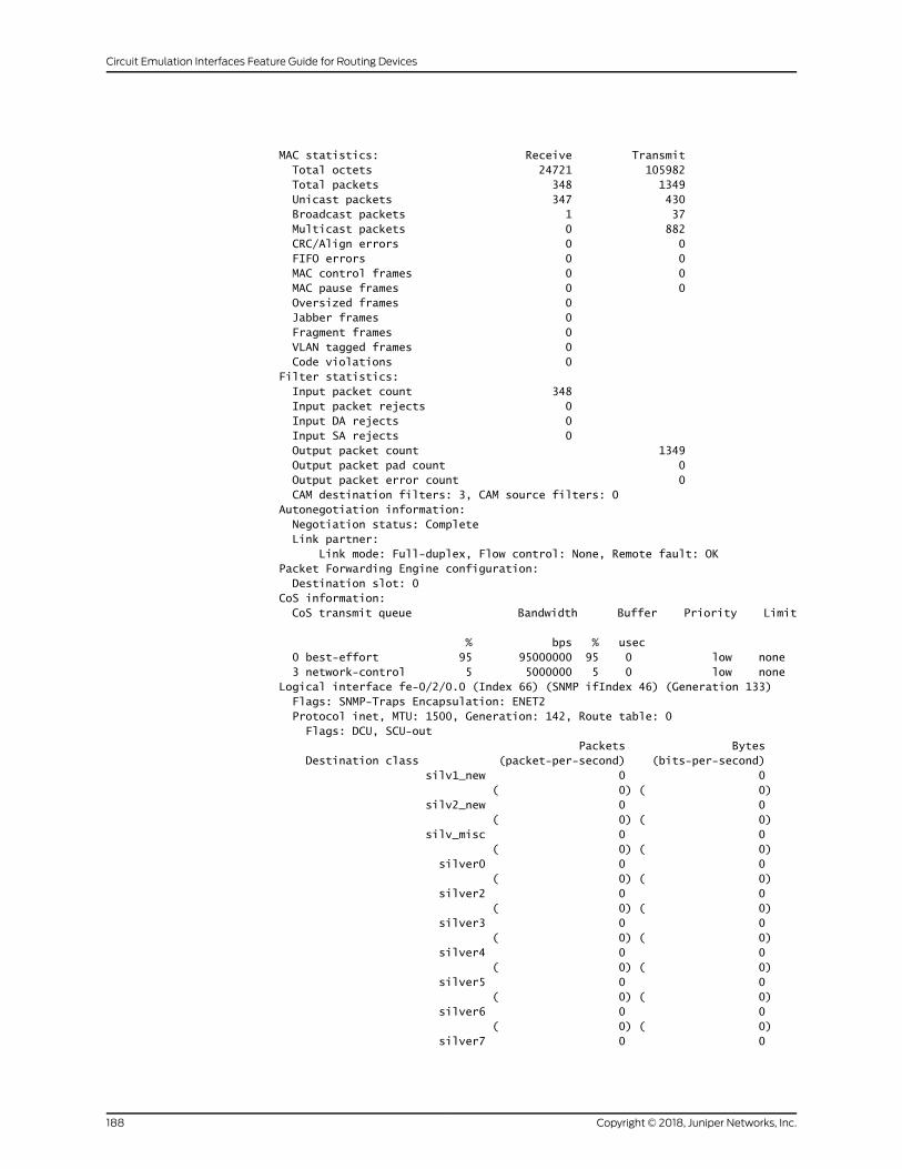
MAC statistics: Receive Transmit Total octets 24721 105982 Total packets 348 1349 Unicast packets 347 430 Broadcast packets 1 37 Multicast packets 0 882 CRC/Align errors 0 0 FIFO errors 0 0 MAC control frames 0 0 MAC pause frames 0 0 Oversized frames 0 Jabber frames 0 Fragment frames 0 VLAN tagged frames 0 Code violations 0 Filter statistics: Input packet count 348 Input packet rejects 0 Input DA rejects 0 Input SA rejects 0 Output packet count 1349 Output packet pad count 0 Output packet error count 0 CAM destination filters: 3, CAM source filters: 0 Autonegotiation information: Negotiation status: Complete Link partner: Link mode: Full-duplex, Flow control: None, Remote fault: OK Packet Forwarding Engine configuration: Destination slot: 0 CoS information: CoS transmit queue Bandwidth Buffer Priority Limit
% bps % usec 0 best-effort 95 95000000 95 0 low none 3 network-control 5 5000000 5 0 low none Logical interface fe-0/2/0.0 (Index 66) (SNMP ifIndex 46) (Generation 133) Flags: SNMP-Traps Encapsulation: ENET2 Protocol inet, MTU: 1500, Generation: 142, Route table: 0 Flags: DCU, SCU-out Packets Bytes Destination class (packet-per-second) (bits-per-second) silv1_new 0 0 ( 0) ( 0) silv2_new 0 0 ( 0) ( 0) silv_misc 0 0 ( 0) ( 0) silver0 0 0 ( 0) ( 0) silver2 0 0 ( 0) ( 0) silver3 0 0 ( 0) ( 0) silver4 0 0 ( 0) ( 0) silver5 0 0 ( 0) ( 0) silver6 0 0 ( 0) ( 0) silver7 0 0
Copyright © 2018, Juniper Networks, Inc.188
Circuit Emulation Interfaces Feature Guide for Routing Devices
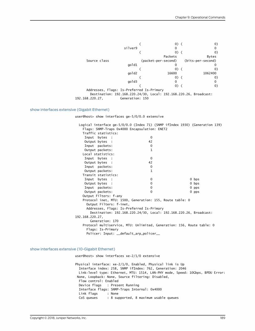
( 0) ( 0) silver9 0 0 ( 0) ( 0) Packets Bytes Source class (packet-per-second) (bits-per-second) gold1 0 0 ( 0) ( 0) gold2 16600 1062400 ( 0) ( 0) gold3 0 0 ( 0) ( 0) Addresses, Flags: Is-Preferred Is-Primary Destination: 192.168.220.24/30, Local: 192.168.220.26, Broadcast: 192.168.220.27, Generation: 150
show interfaces extensive (Gigabit Ethernet)
user@host> show interfaces ge-5/0/0.0 extensive
Logical interface ge-5/0/0.0 (Index 71) (SNMP ifIndex 1930) (Generation 139) Flags: SNMP-Traps 0x4000 Encapsulation: ENET2 Traffic statistics: Input bytes : 0 Output bytes : 42 Input packets: 0 Output packets: 1 Local statistics: Input bytes : 0 Output bytes : 42 Input packets: 0 Output packets: 1 Transit statistics: Input bytes : 0 0 bps Output bytes : 0 0 bps Input packets: 0 0 pps Output packets: 0 0 pps Output Filters: f-any Protocol inet, MTU: 1500, Generation: 155, Route table: 0 Output Filters: f-inet, Addresses, Flags: Is-Preferred Is-Primary Destination: 192.168.220.24/30, Local: 192.168.220.26, Broadcast: 192.168.220.27, Generation: 170 Protocol multiservice, MTU: Unlimited, Generation: 156, Route table: 0 Flags: Is-Primary Policer: Input: __default_arp_policer__
show interfaces extensive (10-Gigabit Ethernet)
user@host> show interfaces xe-2/1/0 extensive
Physical interface: xe-2/1/0, Enabled, Physical link is Up Interface index: 258, SNMP ifIndex: 762, Generation: 2046 Link-level type: Ethernet, MTU: 1514, LAN-PHY mode, Speed: 10Gbps, BPDU Error: None, Loopback: None, Source filtering: Disabled, Flow control: Enabled Device flags : Present Running Interface flags: SNMP-Traps Internal: 0x4000 Link flags : None CoS queues : 8 supported, 8 maximum usable queues
189Copyright © 2018, Juniper Networks, Inc.
Chapter 9: Operational Commands

Hold-times : Up 0 ms, Down 0 ms Current address: 00:00:5E:00:53:00, Hardware address: 00:00:5E:00:53:00 Last flapped : 2011-12-17 00:19:02 PST (07:36:37 ago) Statistics last cleared: 2011-12-17 07:55:24 PST (00:00:15 ago) Traffic statistics: Input bytes : 110000 0 bps Output bytes : 0 0 bps Input packets: 1000 0 pps Output packets: 0 0 pps IPv6 transit statistics: Input bytes : 110000 Output bytes : 0 Input packets: 1000 Output packets: 0 Input errors: Errors: 0, Drops: 0, Framing errors: 0, Runts: 0, Policed discards: 0, L3 incompletes: 0, L2 channel errors: 0, L2 mismatch timeouts: 0, FIFO errors: 0, Resource errors: 0 Output errors: Carrier transitions: 0, Errors: 0, Drops: 0, Collisions: 0, Aged packets: 0, FIFO errors: 0, HS link CRC errors: 0, MTU errors: 0, Resource errors: 0 Egress queues: 8 supported, 4 in use Queue counters: Queued packets Transmitted packets Dropped packets
0 best-effort 0 0 0
1 expedited-fo 0 0 0
2 assured-forw 0 0 0
3 network-cont 0 0 0
Queue number: Mapped forwarding classes 0 best-effort 1 expedited-forwarding 2 assured-forwarding 3 network-control Active alarms : None Active defects : None PCS statistics Seconds Bit errors 0 Errored blocks 0 MAC statistics: Receive Transmit Total octets 128000 0 Total packets 1000 0 Unicast packets 1000 0 Broadcast packets 0 0 Multicast packets 0 0 CRC/Align errors 0 0 FIFO errors 0 0 MAC control frames 0 0 MAC pause frames 0 0 Oversized frames 0 Jabber frames 0 Fragment frames 0 VLAN tagged frames 0 Code violations 0 Filter statistics: Input packet count 1000 Input packet rejects 0
Copyright © 2018, Juniper Networks, Inc.190
Circuit Emulation Interfaces Feature Guide for Routing Devices
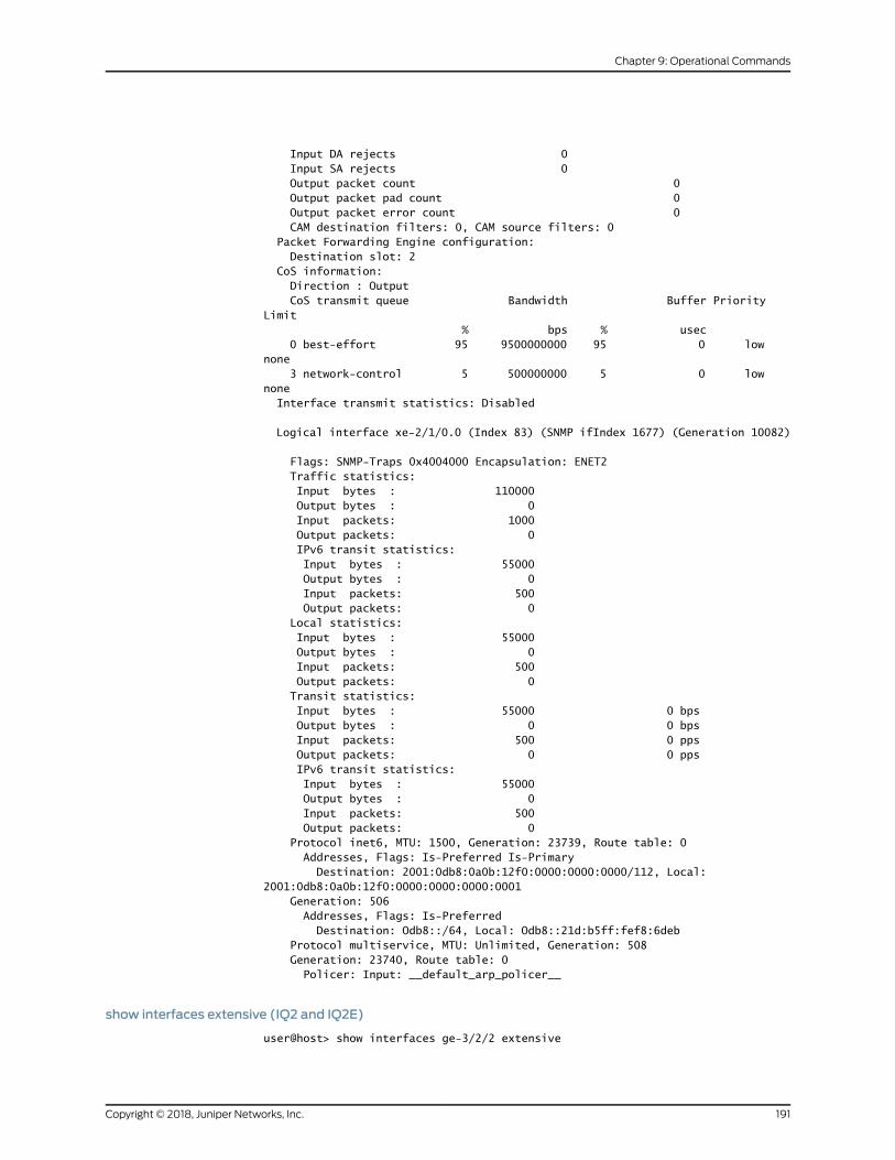
Input DA rejects 0 Input SA rejects 0 Output packet count 0 Output packet pad count 0 Output packet error count 0 CAM destination filters: 0, CAM source filters: 0 Packet Forwarding Engine configuration: Destination slot: 2 CoS information: Direction : Output CoS transmit queue Bandwidth Buffer Priority Limit % bps % usec 0 best-effort 95 9500000000 95 0 low none 3 network-control 5 500000000 5 0 low none Interface transmit statistics: Disabled
Logical interface xe-2/1/0.0 (Index 83) (SNMP ifIndex 1677) (Generation 10082)
Flags: SNMP-Traps 0x4004000 Encapsulation: ENET2 Traffic statistics: Input bytes : 110000 Output bytes : 0 Input packets: 1000 Output packets: 0 IPv6 transit statistics: Input bytes : 55000 Output bytes : 0 Input packets: 500 Output packets: 0 Local statistics: Input bytes : 55000 Output bytes : 0 Input packets: 500 Output packets: 0 Transit statistics: Input bytes : 55000 0 bps Output bytes : 0 0 bps Input packets: 500 0 pps Output packets: 0 0 pps IPv6 transit statistics: Input bytes : 55000 Output bytes : 0 Input packets: 500 Output packets: 0 Protocol inet6, MTU: 1500, Generation: 23739, Route table: 0 Addresses, Flags: Is-Preferred Is-Primary Destination: 2001:0db8:0a0b:12f0:0000:0000:0000/112, Local: 2001:0db8:0a0b:12f0:0000:0000:0000:0001 Generation: 506 Addresses, Flags: Is-Preferred Destination: Odb8::/64, Local: Odb8::21d:b5ff:fef8:6deb Protocol multiservice, MTU: Unlimited, Generation: 508 Generation: 23740, Route table: 0 Policer: Input: __default_arp_policer__
show interfaces extensive (IQ2 and IQ2E)
user@host> show interfaces ge-3/2/2 extensive
191Copyright © 2018, Juniper Networks, Inc.
Chapter 9: Operational Commands

Physical interface: ge-3/2/2, Enabled, Physical link is Up Interface index: 156, SNMP ifIndex: 548, Generation: 159 Link-level type: Ethernet, MTU: 1518, Speed: 1000mbps, BPDU Error: None, MAC-REWRITE Error: None, Loopback: Disabled, Source filtering: Disabled, Flow control: Enabled, Auto-negotiation: Enabled, Remote fault: Online Device flags : Present Running Interface flags: SNMP-Traps Internal: 0x4000 CoS queues : 8 supported, 8 maximum usable queues Schedulers : 128 Hold-times : Up 0 ms, Down 0 ms Current address: 00:00:5E:00:53:00, Hardware address: 00:00:5E:00:53:00 Last flapped : 2010-03-17 04:03:11 PDT (00:45:30 ago) Statistics last cleared: Never Traffic statistics: Input bytes : 1716096 0 bps Output bytes : 1716448 0 bps Input packets: 13407 0 pps Output packets: 13411 0 pps IPv6 total statistics: Input bytes : 1716096 Output bytes : 1716096 Input packets: 13407 Output packets: 13407 Ingress traffic statistics at Packet Forwarding Engine: Input bytes : 1716096 0 bps Input packets: 13407 0 pps Drop bytes : 0 0 bps Drop packets: 0 0 pps Input errors: Errors: 0, Drops: 0, Framing errors: 0, Runts: 0, Policed discards: 0, L3 incompletes: 0, L2 channel errors: 1, L2 mismatch timeouts: 0, FIFO errors: 0, Resource errors: 0 Output errors: Carrier transitions: 1, Errors: 0, Drops: 0, Collisions: 0, Aged packets: 0, FIFO errors: 0, HS link CRC errors: 0, MTU errors: 0, Resource errors: 0 Ingress queues: 8 supported, 4 in use Queue counters: Queued packets Transmitted packets Dropped packets 0 best-effort 13407 13407 0 1 expedited-fo 0 0 0 2 assured-forw 0 0 0 3 network-cont 0 0 0 Egress queues: 8 supported, 4 in use Queue counters: Queued packets Transmitted packets Dropped packets 0 best-effort 13407 13407 0 1 expedited-fo 0 0 0 2 assured-forw 0 0 0 3 network-cont 4 4 0 Active alarms : None Active defects : None MAC statistics: Receive Transmit
Copyright © 2018, Juniper Networks, Inc.192
Circuit Emulation Interfaces Feature Guide for Routing Devices

Total octets 1716096 1716448 Total packets 13407 13411 Unicast packets 13407 13407 Broadcast packets 0 0 Multicast packets 0 4 CRC/Align errors 0 0 FIFO errors 0 0 MAC control frames 0 0 MAC pause frames 0 0 Oversized frames 0 Jabber frames 0 Fragment frames 0 VLAN tagged frames 0 Code violations 0 Filter statistics: Input packet count 13407 Input packet rejects 0 Input DA rejects 0 Input SA rejects 0 Output packet count 13411 Output packet pad count 0 Output packet error count 0 CAM destination filters: 0, CAM source filters: 0 Autonegotiation information: Negotiation status: Complete Link partner: Link mode: Full-duplex, Flow control: None, Remote fault: OK Local resolution: Flow control: Symmetric, Remote fault: Link OK Packet Forwarding Engine configuration: Destination slot: 3 CoS information: Direction : Output CoS transmit queue Bandwidth Buffer Priority Limit % bps % usec 0 best-effort 95 950000000 95 0 low none 3 network-control 5 50000000 5 0 low none Direction : Input CoS transmit queue Bandwidth Buffer Priority Limit % bps % usec 0 best-effort 95 950000000 95 0 low none 3 network-control 5 50000000 5 0 low none
Logical interface ge-3/2/2.0 (Index 83) (SNMP ifIndex 6080) (Generation 148) Flags: SNMP-Traps 0x4000 VLAN-Tag [ 0x8100.100 ] Encapsulation: ENET2 Traffic statistics: Input bytes : 0 Output bytes : 336 Input packets: 0 Output packets: 4 IPv6 total statistics: Input bytes : 1716096 Output bytes : 1716096 Input packets: 13407
193Copyright © 2018, Juniper Networks, Inc.
Chapter 9: Operational Commands

Output packets: 13407 Local statistics: Input bytes : 0 Output bytes : 336 Input packets: 0 Output packets: 4 Transit statistics: Input bytes : 0 0 bps Output bytes : 0 0 bps Input packets: 0 0 pps Output packets: 0 0 pps IPv6 total statistics: Input bytes : 1716096 Output bytes : 1716096 Input packets: 13407 Output packets: 13407 Protocol inet6, MTU: 1500, Generation: 159, Route table: 0 Flags: Is-Primary Addresses, Flags: Is-Default Is-Primary Destination: Unspecified, Local: 2000::2 Generation: 146 Addresses, Flags: Is-Preferred Destination: fe80::/64, Local: fe80::214:f600:6412:86fa Protocol multiservice, MTU: Unlimited, Generation: 148 Generation: 160, Route table: 0 Policer: Input: __default_arp_policer__
Logical interface ge-3/2/2.32767 (Index 84) (SNMP ifIndex 6081) (Generation 149) Flags: SNMP-Traps 0x4000 VLAN-Tag [ 0x0000.0 ] Encapsulation: ENET2 Traffic statistics: Input bytes : 0 Output bytes : 0 Input packets: 0 Output packets: 0 Local statistics: Input bytes : 0 Output bytes : 0 Input packets: 0 Output packets: 0 Transit statistics: Input bytes : 0 0 bps Output bytes : 0 0 bps Input packets: 0 0 pps Output packets: 0 0 pps Protocol multiservice, MTU: Unlimited, Generation: 161, Route table: 0 Flags: None Policer: Input: __default_arp_policer__
show interfaces extensive (100-Gigabit Ethernet Type 4 PICwith CFP)
user@host> show interfaces et-0/0/0:0 extensivePhysical interface: et-0/0/0:0, Enabled, Physical link is Down Interface index: 156, SNMP ifIndex: 516, Generation: 163 Link-level type: Ethernet, MTU: 9192, Speed: 50000mbps, BPDU Error: None,MAC-REWRITE Error: None, Loopback: Disabled, Source filtering: Disabled, Flow control: Enabled Device flags : Present Running Down Interface flags: Hardware-Down SNMP-Traps Internal: 0x4000 Link flags : None CoS queues : 8 supported, 8 maximum usable queues
Copyright © 2018, Juniper Networks, Inc.194
Circuit Emulation Interfaces Feature Guide for Routing Devices
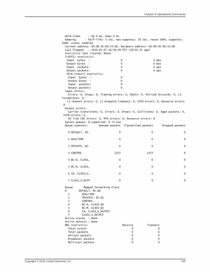
Hold-times : Up 0 ms, Down 0 ms Damping : half-life: 5 sec, max-suppress: 20 sec, reuse 1000, suppress: 2000, state: enabled Current address: 00:00:5E:00:53:00, Hardware address: 00:00:5E:00:53:00 Last flapped : 2010-01-07 16:36:49 PST (18:02:35 ago) Statistics last cleared: Never Traffic statistics: Input bytes : 0 0 bps Output bytes : 0 0 bps Input packets: 0 0 pps Output packets: 0 0 pps IPv6 transit statistics: Input bytes : 0 Output bytes : 0 Input packets: 0 Output packets: 0 Input errors: Errors: 0, Drops: 0, Framing errors: 0, Runts: 0, Policed discards: 0, L3 incompletes: 0, L2 channel errors: 0, L2 mismatch timeouts: 0, FIFO errors: 0, Resource errors: 0 Output errors: Carrier transitions: 0, Errors: 0, Drops: 0, Collisions: 0, Aged packets: 0, FIFO errors: 0, HS link CRC errors: 0, MTU errors: 0, Resource errors: 0 Egress queues: 8 supported, 8 in use Queue counters: Queued packets Transmitted packets Dropped packets
0 DEFAULT, NC- 0 0 0
1 REALTIME 0 0 0
2 PRIVATE, NC- 0 0 0
3 CONTROL 1253 1253 0
4 BC-H, CLASS_ 0 0 0
5 BC-M, CLASS_ 0 0 0
6 IA, CLASS_V_ 0 0 0
7 CLASS_S_OUTP 0 0 0
Queue Mapped Forwarding Class 0 DEFAULT, NC-Q0 1 REALTIME 2 PRIVATE, NC-Q1 3 CONTROL 4 BC-H, CLASS-Q4 5 BC-M, CLASS-Q5 6 IA, CLASS_V_OUTPUT 7 CLASS_S_OUTPUT Active alarms : None Active defects : None MAC statistics: Receive Transmit Total octets 0 0 Total packets 0 0 Unicast packets 0 0 Broadcast packets 0 0 Multicast packets 0 0
195Copyright © 2018, Juniper Networks, Inc.
Chapter 9: Operational Commands

CRC/Align errors 0 0 FIFO errors 0 0 MAC control frames 0 0 MAC pause frames 0 0 Oversized frames 0 Jabber frames 0 Fragment frames 0 VLAN tagged frames 0 Code violations 0 Packet Forwarding Engine configuration: Destination slot: 0 CoS information: Direction : Output CoS transmit queue Bandwidth Buffer Priority Limit
% bps % usec 0 best-effort 95 47500000000 95 0 low none
3 network-control 5 2500000000 5 0 low none
Logical interface et-0/0/0:0.0 (Index 68) (SNMP ifIndex 546) (Generation 161) Flags: Deviet-Down SNMP-Traps Encapsulation: ENET2 Traffic statistics: Input bytes : 0 Output bytes : 0 Input packets: 0 Output packets: 0 Local statistics: Input bytes : 0 Output bytes : 0 Input packets: 0 Output packets: 0 Transit statistics: Input bytes : 0 0 bps Output bytes : 0 0 bps Input packets: 0 0 pps Output packets: 0 0 pps Protocol inet, MTU: 9178, Generation: 220, Route table: 0 Addresses, Flags: Dest-route-down Is-Preferred Is-Primary Destination: 192.168.220.24/30, Local: 192.168.220.26, Broadcast: 192.168.220.27, Generation: 192 Protocol mpls, MTU: 9166, Maximum labels: 3, Generation: 221, Route table: 0
Protocol multiservice, MTU: Unlimited, Generation: 222, Route table: 0 Policer: Input: __default_arp_policer
show interfaces extensive (PTX5000 Packet Transport Router)
user@host> show interfaces et-0/0/6 extensivePhysical interface: et-0/0/6, Enabled, Physical link is Up Interface index: 347, SNMP ifIndex: 531, Generation: 350 Link-level type: Ethernet, MTU: 1514, Speed: 40Gbps, BPDU Error: None, Loop Detect PDU Error: None, Loopback: Disabled, Source filtering: Disabled, Flow control: Enabled Device flags : Present Running Interface flags: SNMP-Traps Internal: 0x4000 Link flags : None CoS queues : 8 supported, 8 maximum usable queues Hold-times : Up 0 ms, Down 0 ms Damping : half-life: 0 sec, max-suppress: 0 sec, reuse: 0, suppress: 0,
Copyright © 2018, Juniper Networks, Inc.196
Circuit Emulation Interfaces Feature Guide for Routing Devices

state: unsuppressed Current address: 30:b6:4f:02:29:06, Hardware address: 30:b6:4f:02:29:06 Last flapped : 2017-02-15 21:40:06 PST (22:55:13 ago) Statistics last cleared: 2017-02-16 20:33:02 PST (00:02:17 ago) Traffic statistics: Input bytes : 1760000 0 bps Output bytes : 1540000 0 bps Input packets: 16000 0 pps Output packets: 14000 0 pps IPv6 transit statistics: Input bytes : 880000 Output bytes : 770000 Input packets: 8000 Output packets: 7000 Input errors: Errors: 0, Drops: 0, Framing errors: 0, Runts: 0, Policed discards: 0, L3 incompletes: 0, L2 channel errors: 0, L2 mismatch timeouts: 0, FIFO errors: 0, Resource errors: 0 Output errors: Carrier transitions: 0, Errors: 0, Drops: 0, Collisions: 0, Aged packets: 0, FIFO errors: 0, HS link CRC errors: 0, MTU errors: 0, Resource errors: 0 Egress queues: 8 supported, 4 in use Queue counters: Queued packets Transmitted packets Dropped packets
0 7000 7000 0
1 0 0 0
2 0 0 0
3 7000 7000 0
Queue number: Mapped forwarding classes 0 best-effort 1 expedited-forwarding 2 assured-forwarding 3 network-control Active alarms : None Active defects : None PCS statistics Seconds Bit errors 0 Errored blocks 0 MAC statistics: Receive Transmit Total octets 2048000 1792000 Total packets 16000 14000 Unicast packets 16000 14000 Broadcast packets 0 0 Multicast packets 0 0 CRC/Align errors 0 0 FIFO errors 0 0 MAC control frames 0 0 MAC pause frames 0 0 Oversized frames 0 Jabber frames 0 Fragment frames 0 VLAN tagged frames 0 Code violations 0 Filter statistics: Input packet count 0 Input packet rejects 0 Input DA rejects 0
197Copyright © 2018, Juniper Networks, Inc.
Chapter 9: Operational Commands

Input SA rejects 0 Output packet count 0 Output packet pad count 0 Output packet error count 0 CAM destination filters: 0, CAM source filters: 0 Packet Forwarding Engine configuration: Destination slot: 0 (0x00) CoS information: Direction : Output CoS transmit queue Bandwidth Buffer Priority Limit % bps % usec 0 best-effort 95 38000000000 95 0 low none 3 network-control 5 2000000000 5 0 low none Preclassifier statistics: Traffic Class Received Packets Transmitted Packets Dropped Packets best-effort 0 0 0 best-effort 0 0 0 best-effort 0 0 0 best-effort 0 0 0 best-effort 0 0 0 best-effort 0 0 0 best-effort 0 0 0 best-effort 0 0 0 Link Degrade : Link Monitoring : Disable Interface transmit statistics: Disabled
Logical interface et-0/0/6.0 (Index 93) (SNMP ifIndex 841) (Generation 158) Flags: Up SNMP-Traps 0x4004000 Encapsulation: ENET2 Traffic statistics: Input bytes : 1760000 Output bytes : 1540000 Input packets: 16000 Output packets: 14000 IPv6 transit statistics: Input bytes : 880000 Output bytes : 770000 Input packets: 8000 Output packets: 7000 Local statistics: Input bytes : 0 Output bytes : 0 Input packets: 0 Output packets: 0 Transit statistics: Input bytes : 1760000 0 bps Output bytes : 1540000 0 bps Input packets: 16000 0 pps Output packets: 14000 0 pps
Copyright © 2018, Juniper Networks, Inc.198
Circuit Emulation Interfaces Feature Guide for Routing Devices

IPv6 transit statistics: Input bytes : 880000 Output bytes : 770000 Input packets: 8000 Output packets: 7000 Protocol inet, MTU: 1500 Max nh cache: 100000, New hold nh limit: 100000, Curr nh cnt: 1, Curr new hold cnt: 0, NH drop cnt: 0 Generation: 206, Route table: 0 Flags: Sendbcast-pkt-to-re Addresses, Flags: Is-Preferred Is-Primary Destination: 11.0.0/24, Local: 11.0.0.2, Broadcast: 11.0.0.255, Generation: 228 Protocol inet6, MTU: 1500 Max nh cache: 100000, New hold nh limit: 100000, Curr nh cnt: 1, Curr new hold cnt: 0, NH drop cnt: 0 Generation: 207, Route table: 0 Addresses, Flags: Is-Preferred Is-Primary Destination: 1100::/120, Local: 1100::2 Generation: 230 Addresses, Flags: Is-Preferred Destination: fe80::/64, Local: fe80::32b6:4fff:fe02:2906 Protocol multiservice, MTU: Unlimited, Generation: 232 Generation: 208, Route table: 0 Policer: Input: __default_arp_policer__
sshow interfaces extensive (PTX Routers)
user@host> show interfaces ae31 extensivePhysical interface: ae31, Enabled, Physical link is Up Interface index: 137, SNMP ifIndex: 511, Generation: 140 Link-level type: Ethernet, MTU: 1518, Speed: 3Gbps, BPDU Error: None, MAC-REWRITE Error: None, Loopback: Disabled, Source filtering: Disabled, Flow control: Disabled Pad to minimum frame size: Disabled Minimum links needed: 1, Minimum bandwidth needed: 1bps Device flags : Present Running Interface flags: SNMP-Traps Internal: 0x4000, LAG_Enhanced
show interfaces extensive (PTX10008 Routers)
user@host> show interfaces ae0 extensivePhysical interface: ae0, Enabled, Physical link is Up Interface index: 917, SNMP ifIndex: 817, Generation: 4436 Link-level type: Ethernet, MTU: 1518, Speed: 20Gbps, BPDU Error: None, MAC-REWRITE Error: None, Loopback: Disabled, Source filtering: Disabled, Flow control: Disabled, Minimum links needed: 1, Minimum bandwidth needed: 1bps Device flags : Present Running Interface flags: SNMP-Traps Internal: 0x4000 Current address: 30:b6:4f:e9:7c:05, Hardware address: 30:b6:4f:e9:7c:05 Last flapped : 2017-04-10 05:20:29 PDT (00:03:52 ago) Statistics last cleared: 2017-04-10 05:21:52 PDT (00:02:29 ago) Traffic statistics: Input bytes : 36463816334 0 bps Output bytes : 36463816334 0 bps Input packets: 24671053 0 pps Output packets: 24671053 0 pps IPv6 transit statistics:
199Copyright © 2018, Juniper Networks, Inc.
Chapter 9: Operational Commands
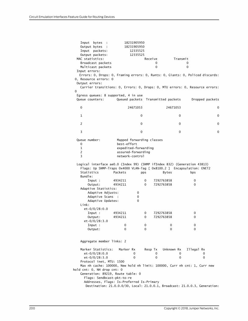
Input bytes : 18231905950 Output bytes : 18231905950 Input packets: 12335525 Output packets: 12335525 MAC statistics: Receive Transmit Broadcast packets 0 0 Multicast packets 0 0 Input errors: Errors: 0, Drops: 0, Framing errors: 0, Runts: 0, Giants: 0, Policed discards: 0, Resource errors: 0 Output errors: Carrier transitions: 0, Errors: 0, Drops: 0, MTU errors: 0, Resource errors: 0 Egress queues: 8 supported, 4 in use Queue counters: Queued packets Transmitted packets Dropped packets
0 24671053 24671053 0
1 0 0 0
2 0 0 0
3 0 0 0
Queue number: Mapped forwarding classes 0 best-effort 1 expedited-forwarding 2 assured-forwarding 3 network-control
Logical interface ae0.0 (Index 99) (SNMP ifIndex 832) (Generation 43813) Flags: Up SNMP-Traps 0x4000 VLAN-Tag [ 0x8100.2 ] Encapsulation: ENET2 Statistics Packets pps Bytes bps Bundle: Input : 4934211 0 7292763858 0 Output: 4934211 0 7292763858 0 Adaptive Statistics: Adaptive Adjusts: 0 Adaptive Scans : 0 Adaptive Updates: 0 Link: et-0/0/28:0.0 Input : 4934211 0 7292763858 0 Output: 4934211 0 7292763858 0 et-0/0/28:3.0 Input : 0 0 0 0 Output: 0 0 0 0
Aggregate member links: 2
Marker Statistics: Marker Rx Resp Tx Unknown Rx Illegal Rx et-0/0/28:0.0 0 0 0 0 et-0/0/28:3.0 0 0 0 0 Protocol inet, MTU: 1500 Max nh cache: 100000, New hold nh limit: 100000, Curr nh cnt: 1, Curr new hold cnt: 0, NH drop cnt: 0 Generation: 89219, Route table: 0 Flags: Sendbcast-pkt-to-re Addresses, Flags: Is-Preferred Is-Primary Destination: 21.0.0.0/30, Local: 21.0.0.1, Broadcast: 21.0.0.3, Generation:
Copyright © 2018, Juniper Networks, Inc.200
Circuit Emulation Interfaces Feature Guide for Routing Devices

62420 Protocol inet6, MTU: 1500 Max nh cache: 100000, New hold nh limit: 100000, Curr nh cnt: 2, Curr new hold cnt: 0, NH drop cnt: 0 Generation: 89220, Route table: 0 Addresses, Flags: Is-Preferred Is-Primary Destination: 3001::1500:0/126, Local: 3001::1500:1 Generation: 62422 Addresses, Flags: Is-Preferred Destination: fe80::/64, Local: fe80::32b6:4f00:2e9:7c05 Protocol multiservice, MTU: Unlimited, Generation: 62424 Generation: 89221, Route table: 0 Policer: Input: __default_arp_policer__
Logical interface ae0.1 (Index 100) (SNMP ifIndex 833) (Generation 43814) Flags: Up SNMP-Traps 0x4000 VLAN-Tag [ 0x8100.3 ] Encapsulation: ENET2 Statistics Packets pps Bytes bps Bundle: Input : 4934211 0 7292763858 0 Output: 4934211 0 7292763858 0 Adaptive Statistics: Adaptive Adjusts: 0 Adaptive Scans : 0 Adaptive Updates: 0 Link: et-0/0/28:0.1 Input : 0 0 0 0 Output: 4934211 0 7292763858 0 et-0/0/28:3.1 Input : 4934211 0 7292763858 0 Output: 0 0 0 0 Marker Statistics: Marker Rx Resp Tx Unknown Rx Illegal Rx et-0/0/28:0.1 0 0 0 0 et-0/0/28:3.1 0 0 0 0 Protocol inet, MTU: 1500 Max nh cache: 100000, New hold nh limit: 100000, Curr nh cnt: 1, Curr new hold cnt: 0, NH drop cnt: 0 Generation: 89222, Route table: 0 Flags: Sendbcast-pkt-to-re Addresses, Flags: Is-Preferred Is-Primary Destination: 21.0.0.4/30, Local: 21.0.0.5, Broadcast: 21.0.0.7, Generation: 62426 Protocol inet6, MTU: 1500 Max nh cache: 100000, New hold nh limit: 100000, Curr nh cnt: 2, Curr new hold cnt: 0, NH drop cnt: 0 Generation: 89223, Route table: 0 Addresses, Flags: Is-Preferred Is-Primary Destination: 3001::1500:4/126, Local: 3001::1500:5 Generation: 62428 Addresses, Flags: Is-Preferred Destination: fe80::/64, Local: fe80::32b6:4f00:3e9:7c05 Protocol multiservice, MTU: Unlimited, Generation: 62430 Generation: 89224, Route table: 0 Policer: Input: __default_arp_policer__
Logical interface ae0.2 (Index 101) (SNMP ifIndex 834) (Generation 43815) Flags: Up SNMP-Traps 0x4000 VLAN-Tag [ 0x8100.4 ] Encapsulation: ENET2 Statistics Packets pps Bytes bps Bundle: Input : 4934211 0 7292763858 0 Output: 4934211 0 7292763858 0
201Copyright © 2018, Juniper Networks, Inc.
Chapter 9: Operational Commands

Adaptive Statistics: Adaptive Adjusts: 0 Adaptive Scans : 0 Adaptive Updates: 0 Link: et-0/0/28:0.2 Input : 2467106 0 3646382668 0 Output: 4934211 0 7292763858 0 et-0/0/28:3.2 Input : 2467105 0 3646381190 0 Output: 0 0 0 0 Marker Statistics: Marker Rx Resp Tx Unknown Rx Illegal Rx et-0/0/28:0.2 0 0 0 0 et-0/0/28:3.2 0 0 0 0 Protocol inet, MTU: 1500 Max nh cache: 100000, New hold nh limit: 100000, Curr nh cnt: 1, Curr new hold cnt: 0, NH drop cnt: 0 Generation: 89225, Route table: 0 Flags: Sendbcast-pkt-to-re Addresses, Flags: Is-Preferred Is-Primary Destination: 21.0.0.8/30, Local: 21.0.0.9, Broadcast: 21.0.0.11, Generation: 62432 Protocol inet6, MTU: 1500 Max nh cache: 100000, New hold nh limit: 100000, Curr nh cnt: 1, Curr new hold cnt: 0, NH drop cnt: 0 Generation: 89226, Route table: 0 Addresses, Flags: Is-Preferred Is-Primary Destination: 3001::1500:8/126, Local: 3001::1500:9 Generation: 62434 Addresses, Flags: Is-Preferred Destination: fe80::/64, Local: fe80::32b6:4f00:4e9:7c05 Protocol multiservice, MTU: Unlimited, Generation: 62436 Generation: 89227, Route table: 0 Policer: Input: __default_arp_policer__
Logical interface ae0.3 (Index 102) (SNMP ifIndex 835) (Generation 43816) Flags: Up SNMP-Traps 0x4000 VLAN-Tag [ 0x8100.5 ] Encapsulation: ENET2 Statistics Packets pps Bytes bps Bundle: Input : 4934210 0 7292762380 0 Output: 4934210 0 7292762380 0 Adaptive Statistics: Adaptive Adjusts: 0 Adaptive Scans : 0 Adaptive Updates: 0 Link: et-0/0/28:0.3 Input : 4934210 0 7292762380 0 Output: 0 0 0 0 et-0/0/28:3.3 Input : 0 0 0 0 Output: 4934210 0 7292762380 0 Marker Statistics: Marker Rx Resp Tx Unknown Rx Illegal Rx et-0/0/28:0.3 0 0 0 0 et-0/0/28:3.3 0 0 0 0 Protocol inet, MTU: 1500 Max nh cache: 100000, New hold nh limit: 100000, Curr nh cnt: 1, Curr new hold cnt: 0, NH drop cnt: 0 Generation: 89228, Route table: 0 Flags: Sendbcast-pkt-to-re Addresses, Flags: Is-Preferred Is-Primary
Copyright © 2018, Juniper Networks, Inc.202
Circuit Emulation Interfaces Feature Guide for Routing Devices

Destination: 21.0.0.12/30, Local: 21.0.0.13, Broadcast: 21.0.0.15, Generation: 62438 Protocol inet6, MTU: 1500 Max nh cache: 100000, New hold nh limit: 100000, Curr nh cnt: 2, Curr new hold cnt: 0, NH drop cnt: 0 Generation: 89229, Route table: 0 Addresses, Flags: Is-Preferred Is-Primary Destination: 3001::1500:c/126, Local: 3001::1500:d Generation: 62440 Addresses, Flags: Is-Preferred Destination: fe80::/64, Local: fe80::32b6:4f00:5e9:7c05 Protocol multiservice, MTU: Unlimited, Generation: 62442 Generation: 89230, Route table: 0 Policer: Input: __default_arp_policer__
Logical interface ae0.4 (Index 103) (SNMP ifIndex 836) (Generation 43817) Flags: Up SNMP-Traps 0x4000 VLAN-Tag [ 0x8100.6 ] Encapsulation: ENET2 Statistics Packets pps Bytes bps Bundle: Input : 4934210 0 7292762380 0 Output: 4934210 0 7292762380 0 Adaptive Statistics: Adaptive Adjusts: 0 Adaptive Scans : 0 Adaptive Updates: 0 Link: et-0/0/28:0.4 Input : 2467105 0 3646381190 0 Output: 2467105 0 3646381190 0 et-0/0/28:3.4 Input : 2467105 0 3646381190 0 Output: 2467105 0 3646381190 0 Marker Statistics: Marker Rx Resp Tx Unknown Rx Illegal Rx et-0/0/28:0.4 0 0 0 0 et-0/0/28:3.4 0 0 0 0 Protocol inet, MTU: 1500 Max nh cache: 100000, New hold nh limit: 100000, Curr nh cnt: 1, Curr new hold cnt: 0, NH drop cnt: 0 Generation: 89231, Route table: 0 Flags: Sendbcast-pkt-to-re Addresses, Flags: Is-Preferred Is-Primary Destination: 21.0.0.16/30, Local: 21.0.0.17, Broadcast: 21.0.0.19, Generation: 62444 Protocol inet6, MTU: 1500 Max nh cache: 100000, New hold nh limit: 100000, Curr nh cnt: 2, Curr new hold cnt: 0, NH drop cnt: 0 Generation: 89232, Route table: 0 Addresses, Flags: Is-Preferred Is-Primary Destination: 3001::1500:10/126, Local: 3001::1500:11 Generation: 62446 Addresses, Flags: Is-Preferred Destination: fe80::/64, Local: fe80::32b6:4f00:6e9:7c05 Protocol multiservice, MTU: Unlimited, Generation: 62448 Generation: 89233, Route table: 0 Policer: Input: __default_arp_policer__
Logical interface ae0.32767 (Index 104) (SNMP ifIndex 5645) (Generation 43818)
Flags: Up SNMP-Traps 0x4004000 VLAN-Tag [ 0x0000.0 ] Encapsulation: ENET2 Statistics Packets pps Bytes bps Bundle:
203Copyright © 2018, Juniper Networks, Inc.
Chapter 9: Operational Commands
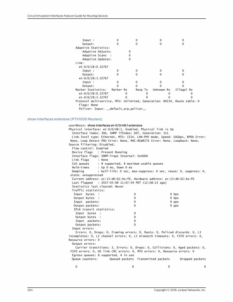
Input : 0 0 0 0 Output: 0 0 0 0 Adaptive Statistics: Adaptive Adjusts: 0 Adaptive Scans : 0 Adaptive Updates: 0 Link: et-0/0/28:0.32767 Input : 0 0 0 0 Output: 0 0 0 0 et-0/0/28:3.32767 Input : 0 0 0 0 Output: 0 0 0 0 Marker Statistics: Marker Rx Resp Tx Unknown Rx Illegal Rx et-0/0/28:0.32767 0 0 0 0 et-0/0/28:3.32767 0 0 0 0 Protocol multiservice, MTU: Unlimited, Generation: 89234, Route table: 0 Flags: None Policer: Input: __default_arp_policer__
show interfaces extensive (PTX1000 Routers)
user@host> show interfaces et-0/0/48:1 extensivePhysical interface: et-0/0/48:1, Enabled, Physical link is Up Interface index: 306, SNMP ifIndex: 697, Generation: 311 Link-level type: Ethernet, MTU: 1514, LAN-PHY mode, Speed: 10Gbps, BPDU Error: None, Loop Detect PDU Error: None, MAC-REWRITE Error: None, Loopback: None, Source filtering: Disabled, Flow control: Enabled Device flags : Present Running Interface flags: SNMP-Traps Internal: 0x4000 Link flags : None CoS queues : 8 supported, 8 maximum usable queues Hold-times : Up 0 ms, Down 0 ms Damping : half-life: 0 sec, max-suppress: 0 sec, reuse: 0, suppress: 0, state: unsuppressed Current address: ec:13:db:62:4a:f6, Hardware address: ec:13:db:62:4a:f6 Last flapped : 2017-05-08 11:07:59 PDT (12:08:13 ago) Statistics last cleared: Never Traffic statistics: Input bytes : 0 0 bps Output bytes : 0 0 bps Input packets: 0 0 pps Output packets: 0 0 pps IPv6 transit statistics: Input bytes : 0 Output bytes : 0 Input packets: 0 Output packets: 0 Input errors: Errors: 0, Drops: 0, Framing errors: 0, Runts: 0, Policed discards: 0, L3 incompletes: 0, L2 channel errors: 0, L2 mismatch timeouts: 0, FIFO errors: 0, Resource errors: 0 Output errors: Carrier transitions: 3, Errors: 0, Drops: 0, Collisions: 0, Aged packets: 0, FIFO errors: 0, HS link CRC errors: 0, MTU errors: 0, Resource errors: 0 Egress queues: 8 supported, 4 in use Queue counters: Queued packets Transmitted packets Dropped packets
0 0 0 0
Copyright © 2018, Juniper Networks, Inc.204
Circuit Emulation Interfaces Feature Guide for Routing Devices
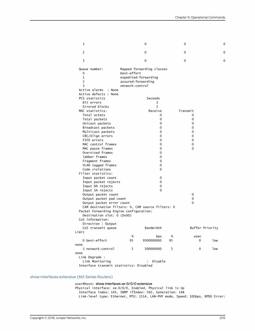
1 0 0 0
2 0 0 0
3 0 0 0
Queue number: Mapped forwarding classes 0 best-effort 1 expedited-forwarding 2 assured-forwarding 3 network-control Active alarms : None Active defects : None PCS statistics Seconds Bit errors 3 Errored blocks 3 MAC statistics: Receive Transmit Total octets 0 0 Total packets 0 0 Unicast packets 0 0 Broadcast packets 0 0 Multicast packets 0 0 CRC/Align errors 0 0 FIFO errors 0 0 MAC control frames 0 0 MAC pause frames 0 0 Oversized frames 0 Jabber frames 0 Fragment frames 0 VLAN tagged frames 0 Code violations 0 Filter statistics: Input packet count 0 Input packet rejects 0 Input DA rejects 0 Input SA rejects 0 Output packet count 0 Output packet pad count 0 Output packet error count 0 CAM destination filters: 0, CAM source filters: 0 Packet Forwarding Engine configuration: Destination slot: 0 (0x00) CoS information: Direction : Output CoS transmit queue Bandwidth Buffer Priority Limit % bps % usec 0 best-effort 95 9500000000 95 0 low none 3 network-control 5 500000000 5 0 low none Link Degrade : Link Monitoring : Disable Interface transmit statistics: Disabled
show interfaces extensive (MX Series Routers)
user@host> show interfaces xe-0/0/0 extensivePhysical interface: xe-0/0/0, Enabled, Physical link is Up Interface index: 145, SNMP ifIndex: 592, Generation: 148 Link-level type: Ethernet, MTU: 1514, LAN-PHY mode, Speed: 10Gbps, BPDU Error:
205Copyright © 2018, Juniper Networks, Inc.
Chapter 9: Operational Commands
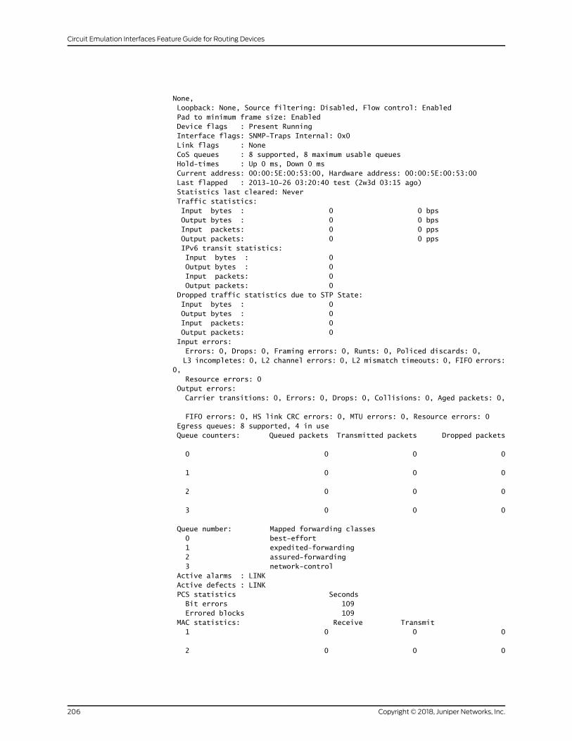
None, Loopback: None, Source filtering: Disabled, Flow control: Enabled Pad to minimum frame size: Enabled Device flags : Present Running Interface flags: SNMP-Traps Internal: 0x0 Link flags : None CoS queues : 8 supported, 8 maximum usable queues Hold-times : Up 0 ms, Down 0 ms Current address: 00:00:5E:00:53:00, Hardware address: 00:00:5E:00:53:00 Last flapped : 2013-10-26 03:20:40 test (2w3d 03:15 ago) Statistics last cleared: Never Traffic statistics: Input bytes : 0 0 bps Output bytes : 0 0 bps Input packets: 0 0 pps Output packets: 0 0 pps IPv6 transit statistics: Input bytes : 0 Output bytes : 0 Input packets: 0 Output packets: 0 Dropped traffic statistics due to STP State: Input bytes : 0 Output bytes : 0 Input packets: 0 Output packets: 0 Input errors: Errors: 0, Drops: 0, Framing errors: 0, Runts: 0, Policed discards: 0, L3 incompletes: 0, L2 channel errors: 0, L2 mismatch timeouts: 0, FIFO errors: 0, Resource errors: 0 Output errors: Carrier transitions: 0, Errors: 0, Drops: 0, Collisions: 0, Aged packets: 0,
FIFO errors: 0, HS link CRC errors: 0, MTU errors: 0, Resource errors: 0 Egress queues: 8 supported, 4 in use Queue counters: Queued packets Transmitted packets Dropped packets
0 0 0 0
1 0 0 0
2 0 0 0
3 0 0 0
Queue number: Mapped forwarding classes 0 best-effort 1 expedited-forwarding 2 assured-forwarding 3 network-control Active alarms : LINK Active defects : LINK PCS statistics Seconds Bit errors 109 Errored blocks 109 MAC statistics: Receive Transmit 1 0 0 0
2 0 0 0
Copyright © 2018, Juniper Networks, Inc.206
Circuit Emulation Interfaces Feature Guide for Routing Devices
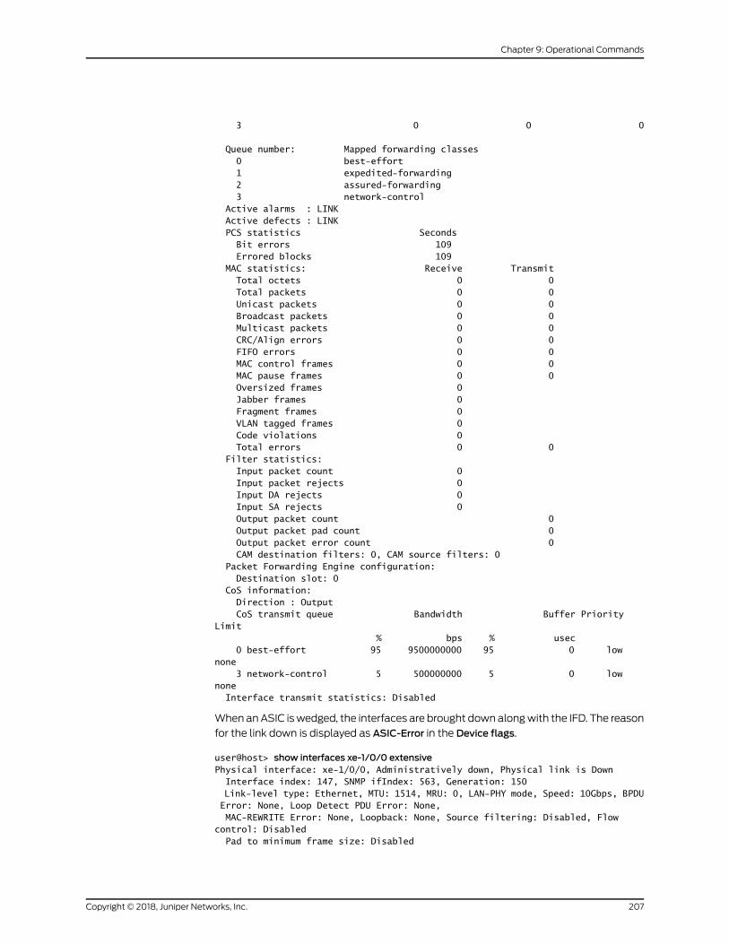
3 0 0 0
Queue number: Mapped forwarding classes 0 best-effort 1 expedited-forwarding 2 assured-forwarding 3 network-control Active alarms : LINK Active defects : LINK PCS statistics Seconds Bit errors 109 Errored blocks 109 MAC statistics: Receive Transmit Total octets 0 0 Total packets 0 0 Unicast packets 0 0 Broadcast packets 0 0 Multicast packets 0 0 CRC/Align errors 0 0 FIFO errors 0 0 MAC control frames 0 0 MAC pause frames 0 0 Oversized frames 0 Jabber frames 0 Fragment frames 0 VLAN tagged frames 0 Code violations 0 Total errors 0 0 Filter statistics: Input packet count 0 Input packet rejects 0 Input DA rejects 0 Input SA rejects 0 Output packet count 0 Output packet pad count 0 Output packet error count 0 CAM destination filters: 0, CAM source filters: 0 Packet Forwarding Engine configuration: Destination slot: 0 CoS information: Direction : Output CoS transmit queue Bandwidth Buffer Priority Limit % bps % usec 0 best-effort 95 9500000000 95 0 low none 3 network-control 5 500000000 5 0 low none Interface transmit statistics: Disabled
WhenanASIC iswedged, the interfaces are brought downalongwith the IFD. The reason
for the link down is displayed as ASIC-Error in the Device flags.
user@host> show interfaces xe-1/0/0 extensivePhysical interface: xe-1/0/0, Administratively down, Physical link is Down Interface index: 147, SNMP ifIndex: 563, Generation: 150 Link-level type: Ethernet, MTU: 1514, MRU: 0, LAN-PHY mode, Speed: 10Gbps, BPDU Error: None, Loop Detect PDU Error: None, MAC-REWRITE Error: None, Loopback: None, Source filtering: Disabled, Flow control: Disabled Pad to minimum frame size: Disabled
207Copyright © 2018, Juniper Networks, Inc.
Chapter 9: Operational Commands

Device flags : Present Running Down ASIC-Error Interface flags: Hardware-Down Down Internal: 0x4000 Link flags : None CoS queues : 8 supported, 8 maximum usable queues Schedulers : 0 Hold-times : Up 0 ms, Down 0 ms Damping : half-life: 0 sec, max-suppress: 0 sec, reuse: 0, suppress: 0, state: unsuppressed Current address: cc:e1:7f:a8:05:4a, Hardware address: cc:e1:7f:a8:05:4a Last flapped : 2017-06-05 17:20:54 PDT (00:03:51 ago) Statistics last cleared: Never
show interfaces extensive (MX480 Router with MPC5E and 10-Gigabit Ethernet OTN Interface)
user@host> show interfaces xe-0/0/3 extensivePhysical interface: xe-0/0/3, Enabled, Physical link is Up Interface index: 200, SNMP ifIndex: 577, Generation: 203 Link-level type: Ethernet, MTU: 1514, MRU: 1522, LAN-PHY mode, Speed: 10Gbps, BPDU Error: None, MAC-REWRITE Error: None, Loopback: None, Source filtering: Disabled, Flow control: Enabled Pad to minimum frame size: Disabled Device flags : Present Running Interface flags: SNMP-Traps Internal: 0x4000 Link flags : None CoS queues : 8 supported, 8 maximum usable queues Schedulers : 0 Hold-times : Up 0 ms, Down 0 ms Current address: 00:00:5E:00:53:00, Hardware address: 00:00:5E:00:53:00 Last flapped : 2014-06-26 18:16:50 PDT (04:58:35 ago) Statistics last cleared: Never Traffic statistics: Input bytes : 0 0 bps Output bytes : 0 0 bps Input packets: 0 0 pps Output packets: 0 0 pps IPv6 transit statistics: Input bytes : 0 Output bytes : 0 Input packets: 0 Output packets: 0 Dropped traffic statistics due to STP State: Input bytes : 0 Output bytes : 0 Input packets: 0 Output packets: 0 Input errors: Errors: 0, Drops: 0, Framing errors: 0, Runts: 0, Policed discards: 0, L3 incompletes: 0, L2 channel errors: 0, L2 mismatch timeouts: 0, FIFO errors: 0, Resource errors: 0 Output errors: Carrier transitions: 5, Errors: 0, Drops: 0, Collisions: 0, Aged packets: 0, FIFO errors: 0, HS link CRC errors: 0, MTU errors: 0, Resource errors: 0 Egress queues: 8 supported, 4 in use Queue counters: Queued packets Transmitted packets Dropped packets
0 0 0 0
1 0 0 0
2 0 0 0
Copyright © 2018, Juniper Networks, Inc.208
Circuit Emulation Interfaces Feature Guide for Routing Devices

3 0 0 0
Queue number: Mapped forwarding classes 0 best-effort 1 expedited-forwarding 2 assured-forwarding 3 network-control Active alarms : None Active defects : None PCS statistics Seconds Bit errors 0 Errored blocks 4 MAC statistics: Receive Transmit Total octets 0 0 Total packets 0 0 Unicast packets 0 0 Broadcast packets 0 0 Multicast packets 0 0 CRC/Align errors 0 0 FIFO errors 0 0 MAC control frames 0 0 MAC pause frames 0 0 Oversized frames 0 Jabber frames 0 Fragment frames 0 VLAN tagged frames 0 Code violations 0 Total errors 0 0 Filter statistics: Input packet count 0 Input packet rejects 0 Input DA rejects 0 Input SA rejects 0 Output packet count 0 Output packet pad count 0 Output packet error count 0 CAM destination filters: 0, CAM source filters: 0 Packet Forwarding Engine configuration: Destination slot: 0 (0x00) CoS information: Direction : Output CoS transmit queue Bandwidth Buffer Priority Limit % bps % usec 0 best-effort 95 9500000000 95 0 low none 3 network-control 5 500000000 5 0 low none Interface transmit statistics: Disabled
show interfaces extensive (MX480 Router with MPC5E and 100-Gigabit Ethernet OTN Interface)
user@host> show interfaces et-2/1/0 extensivePhysical interface: et-2/1/0, Enabled, Physical link is Up Interface index: 215, SNMP ifIndex: 872, Generation: 218 Link-level type: Ethernet, MTU: 1514, MRU: 1522, Speed: 100Gbps, BPDU Error: None, Loopback: Disabled, Source filtering: Disabled, Flow control: Enabled Pad to minimum frame size: Disabled Device flags : Present Running Interface flags: SNMP-Traps Internal: 0x4000 Link flags : None
209Copyright © 2018, Juniper Networks, Inc.
Chapter 9: Operational Commands
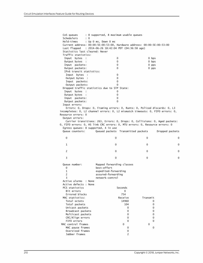
CoS queues : 8 supported, 8 maximum usable queues Schedulers : 0 Hold-times : Up 0 ms, Down 0 ms Current address: 00:00:5E:00:53:00, Hardware address: 00:00:5E:00:53:00 Last flapped : 2014-06-26 18:42:04 PDT (04:36:58 ago) Statistics last cleared: Never Traffic statistics: Input bytes : 0 0 bps Output bytes : 0 0 bps Input packets: 0 0 pps Output packets: 0 0 pps IPv6 transit statistics: Input bytes : 0 Output bytes : 0 Input packets: 0 Output packets: 0 Dropped traffic statistics due to STP State: Input bytes : 0 Output bytes : 0 Input packets: 0 Output packets: 0 Input errors: Errors: 0, Drops: 0, Framing errors: 0, Runts: 0, Policed discards: 0, L3 incompletes: 0, L2 channel errors: 0, L2 mismatch timeouts: 0, FIFO errors: 0, Resource errors: 0 Output errors: Carrier transitions: 263, Errors: 0, Drops: 0, Collisions: 0, Aged packets: 0, FIFO errors: 0, HS link CRC errors: 0, MTU errors: 0, Resource errors: 0 Egress queues: 8 supported, 4 in use Queue counters: Queued packets Transmitted packets Dropped packets
0 0 0 0
1 0 0 0
2 0 0 0
3 0 0 0
Queue number: Mapped forwarding classes 0 best-effort 1 expedited-forwarding 2 assured-forwarding 3 network-control Active alarms : None Active defects : None PCS statistics Seconds Bit errors 0 Errored blocks 754 MAC statistics: Receive Transmit Total octets 14960 0 Total packets 104 0 Unicast packets 0 0 Broadcast packets 0 0 Multicast packets 0 0 CRC/Align errors 0 0 FIFO errors 0 0 MAC control frames 0 0 MAC pause frames 0 0 Oversized frames 0 Jabber frames 2
Copyright © 2018, Juniper Networks, Inc.210
Circuit Emulation Interfaces Feature Guide for Routing Devices
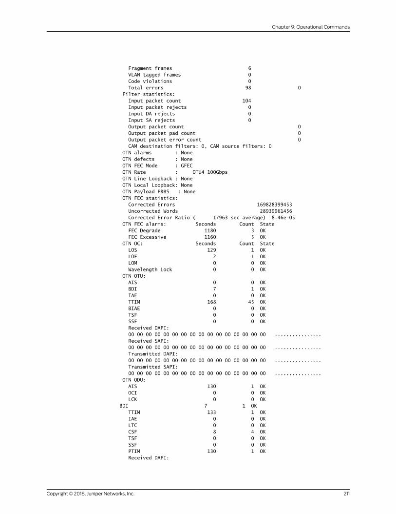
Fragment frames 6 VLAN tagged frames 0 Code violations 0 Total errors 98 0 Filter statistics: Input packet count 104 Input packet rejects 0 Input DA rejects 0 Input SA rejects 0 Output packet count 0 Output packet pad count 0 Output packet error count 0 CAM destination filters: 0, CAM source filters: 0 OTN alarms : None OTN defects : None OTN FEC Mode : GFEC OTN Rate : OTU4 100Gbps OTN Line Loopback : None OTN Local Loopback: None OTN Payload PRBS : None OTN FEC statistics: Corrected Errors 169828399453 Uncorrected Words 28939961456 Corrected Error Ratio ( 17963 sec average) 8.46e-05 OTN FEC alarms: Seconds Count State FEC Degrade 1180 3 OK FEC Excessive 1160 5 OK OTN OC: Seconds Count State LOS 129 1 OK LOF 2 1 OK LOM 0 0 OK Wavelength Lock 0 0 OK OTN OTU: AIS 0 0 OK BDI 7 1 OK IAE 0 0 OK TTIM 168 45 OK BIAE 0 0 OK TSF 0 0 OK SSF 0 0 OK Received DAPI: 00 00 00 00 00 00 00 00 00 00 00 00 00 00 00 00 ................ Received SAPI: 00 00 00 00 00 00 00 00 00 00 00 00 00 00 00 00 ................ Transmitted DAPI: 00 00 00 00 00 00 00 00 00 00 00 00 00 00 00 00 ................ Transmitted SAPI: 00 00 00 00 00 00 00 00 00 00 00 00 00 00 00 00 ................ OTN ODU: AIS 130 1 OK OCI 0 0 OK LCK 0 0 OK BDI 7 1 OK TTIM 133 1 OK IAE 0 0 OK LTC 0 0 OK CSF 8 4 OK TSF 0 0 OK SSF 0 0 OK PTIM 130 1 OK Received DAPI:
211Copyright © 2018, Juniper Networks, Inc.
Chapter 9: Operational Commands
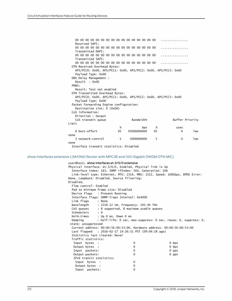
00 00 00 00 00 00 00 00 00 00 00 00 00 00 00 00 ................ Received SAPI: 00 00 00 00 00 00 00 00 00 00 00 00 00 00 00 00 ................ Transmitted DAPI: 00 00 00 00 00 00 00 00 00 00 00 00 00 00 00 00 ................ Transmitted SAPI: 00 00 00 00 00 00 00 00 00 00 00 00 00 00 00 00 ................ OTN Received Overhead Bytes: APS/PCC0: 0x00, APS/PCC1: 0x00, APS/PCC2: 0x00, APS/PCC3: 0x00 Payload Type: 0x00 ODU Delay Management : Result : 0x00 PRBS: Result: Test not enabled OTN Transmitted Overhead Bytes: APS/PCC0: 0x00, APS/PCC1: 0x00, APS/PCC2: 0x00, APS/PCC3: 0x00 Payload Type: 0x00 Packet Forwarding Engine configuration: Destination slot: 0 (0x00) CoS information: Direction : Output CoS transmit queue Bandwidth Buffer Priority Limit % bps % usec 0 best-effort 95 95000000000 95 0 low none 3 network-control 5 5000000000 5 0 low none Interface transmit statistics: Disabled
show interfaces extensive ((MX960 Router with MPC3E and 100-Gigabit DWDMOTNMIC)
user@host> show interfaces et-3/0/0 extensivePhysical interface: et-3/0/0, Enabled, Physical link is Up Interface index: 163, SNMP ifIndex: 564, Generation: 166 Link-level type: Ethernet, MTU: 1514, MRU: 1522, Speed: 100Gbps, BPDU Error: None, Loopback: Disabled, Source filtering: Disabled, Flow control: Enabled Pad to minimum frame size: Disabled Device flags : Present Running Interface flags: SNMP-Traps Internal: 0x4000 Link flags : None Wavelength : 1550.12 nm, Frequency: 193.40 THz CoS queues : 8 supported, 8 maximum usable queues Schedulers : 0 Hold-times : Up 0 ms, Down 0 ms Damping : half-life: 0 sec, max-suppress: 0 sec, reuse: 0, suppress: 0, state: unsuppressed Current address: 00:00:5E:00:53:00, Hardware address: 00:00:5E:00:53:00 Last flapped : 2016-02-17 14:26:31 PST (09:04:28 ago) Statistics last cleared: Never Traffic statistics: Input bytes : 0 0 bps Output bytes : 0 0 bps Input packets: 0 0 pps Output packets: 0 0 pps IPv6 transit statistics: Input bytes : 0 Output bytes : 0 Input packets: 0
Copyright © 2018, Juniper Networks, Inc.212
Circuit Emulation Interfaces Feature Guide for Routing Devices

Output packets: 0 Dropped traffic statistics due to STP State: Input bytes : 0 Output bytes : 0 Input packets: 0 Output packets: 0 Input errors: Errors: 0, Drops: 0, Framing errors: 0, Runts: 0, Policed discards: 0, L3 incompletes: 0, L2 channel errors: 0, L2 mismatch timeouts: 0, FIFO errors: 0, Resource errors: 0 Output errors: Carrier transitions: 5, Errors: 0, Drops: 0, Collisions: 0, Aged packets: 0, FIFO errors: 0, HS link CRC errors: 0, MTU errors: 0, Resource errors: 0 Egress queues: 8 supported, 4 in use Queue counters: Queued packets Transmitted packets Dropped packets
0 0 0 0
1 0 0 0
2 0 0 0
3 0 0 0
Queue number: Mapped forwarding classes 0 best-effort 1 expedited-forwarding 2 assured-forwarding 3 network-control Active alarms : None Active defects : None PCS statistics Seconds Bit errors 8 Errored blocks 10 MAC statistics: Receive Transmit Total octets 0 0 Total packets 0 0 Unicast packets 0 0 Broadcast packets 0 0 Multicast packets 0 0 CRC/Align errors 0 0 FIFO errors 0 0 MAC control frames 0 0 MAC pause frames 0 0 Oversized frames 0 Jabber frames 0 Fragment frames 0 VLAN tagged frames 0 Code violations 0 Total errors 0 0 Filter statistics: Input packet count 0 Input packet rejects 0 Input DA rejects 0 Input SA rejects 0 Output packet count 0 Output packet pad count 0 Output packet error count 0 CAM destination filters: 0, CAM source filters: 0
213Copyright © 2018, Juniper Networks, Inc.
Chapter 9: Operational Commands

OTN alarms : None OTN defects : None OTN FEC Mode : SDFEC OTN Rate : OTU4 (120.5Gbps) OTN Line Loopback : None OTN Local Loopback: None OTN Payload PRBS : None OTN Laser Enable : On OTN FEC statistics: Corrected Errors 7065332638 Uncorrected Words 3412572 Corrected Error Ratio ( 32785 sec average) 1.79e-06 (INVALID) OTN FEC alarms: Seconds Count State FEC Degrade 0 0 OK FEC Excessive 3 1 OK OTN OC: Seconds Count State LOS 3 1 OK LOF 50 3 OK LOM 3 3 OK Wavelength Lock 0 0 OK OTN OTU: AIS 0 0 OK BDI 4 4 OK IAE 4 4 OK TTIM 1 1 OK BIAE 3 3 OK TSF 50 3 OK SSF 50 3 OK Received DAPI: 00 00 00 00 00 00 00 00 00 00 00 00 00 00 00 00 ................ Received SAPI: 00 00 00 00 00 00 00 00 00 00 00 00 00 00 00 00 ................ Transmitted DAPI: 00 00 00 00 00 00 00 00 00 00 00 00 00 00 00 00 ................ Transmitted SAPI: 00 00 00 00 00 00 00 00 00 00 00 00 00 00 00 00 ................ OTN ODU: AIS 20 2 OK OCI 4 4 OK LCK 4 4 OK BDI 2 2 OK TTIM 20 2 OK IAE 0 0 OK LTC 0 0 OK CSF 18 2 OK TSF 66 2 OK SSF 66 2 OK PTIM 43 2 OK Received DAPI: 00 00 00 00 00 00 00 00 00 00 00 00 00 00 00 00 ................ Received SAPI: 00 00 00 00 00 00 00 00 00 00 00 00 00 00 00 00 ................ Transmitted DAPI: 00 00 00 00 00 00 00 00 00 00 00 00 00 00 00 00 ................ Transmitted SAPI: 00 00 00 00 00 00 00 00 00 00 00 00 00 00 00 00 ................ OTN Received Overhead Bytes: APS/PCC0: 0x00, APS/PCC1: 0x00, APS/PCC2: 0x00, APS/PCC3: 0x00 Payload Type: 0x07 ODU Delay Management : Result : 0ms
Copyright © 2018, Juniper Networks, Inc.214
Circuit Emulation Interfaces Feature Guide for Routing Devices
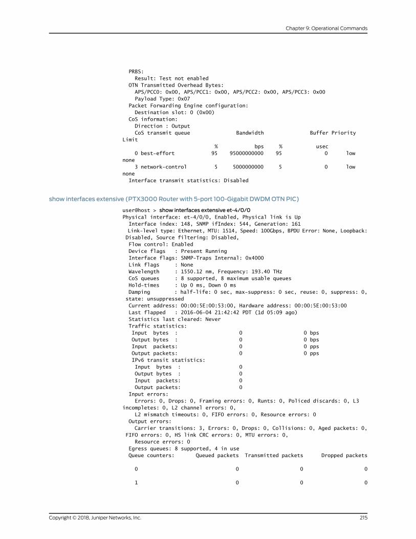
PRBS: Result: Test not enabled OTN Transmitted Overhead Bytes: APS/PCC0: 0x00, APS/PCC1: 0x00, APS/PCC2: 0x00, APS/PCC3: 0x00 Payload Type: 0x07 Packet Forwarding Engine configuration: Destination slot: 0 (0x00) CoS information: Direction : Output CoS transmit queue Bandwidth Buffer Priority Limit % bps % usec 0 best-effort 95 95000000000 95 0 low none 3 network-control 5 5000000000 5 0 low none Interface transmit statistics: Disabled
show interfaces extensive (PTX3000 Router with 5-port 100-Gigabit DWDMOTNPIC)
user@host > show interfaces extensive et-4/0/0Physical interface: et-4/0/0, Enabled, Physical link is Up Interface index: 148, SNMP ifIndex: 544, Generation: 161 Link-level type: Ethernet, MTU: 1514, Speed: 100Gbps, BPDU Error: None, Loopback: Disabled, Source filtering: Disabled, Flow control: Enabled Device flags : Present Running Interface flags: SNMP-Traps Internal: 0x4000 Link flags : None Wavelength : 1550.12 nm, Frequency: 193.40 THz CoS queues : 8 supported, 8 maximum usable queues Hold-times : Up 0 ms, Down 0 ms Damping : half-life: 0 sec, max-suppress: 0 sec, reuse: 0, suppress: 0, state: unsuppressed Current address: 00:00:5E:00:53:00, Hardware address: 00:00:5E:00:53:00 Last flapped : 2016-06-04 21:42:42 PDT (1d 05:09 ago) Statistics last cleared: Never Traffic statistics: Input bytes : 0 0 bps Output bytes : 0 0 bps Input packets: 0 0 pps Output packets: 0 0 pps IPv6 transit statistics: Input bytes : 0 Output bytes : 0 Input packets: 0 Output packets: 0 Input errors: Errors: 0, Drops: 0, Framing errors: 0, Runts: 0, Policed discards: 0, L3 incompletes: 0, L2 channel errors: 0, L2 mismatch timeouts: 0, FIFO errors: 0, Resource errors: 0 Output errors: Carrier transitions: 3, Errors: 0, Drops: 0, Collisions: 0, Aged packets: 0, FIFO errors: 0, HS link CRC errors: 0, MTU errors: 0, Resource errors: 0 Egress queues: 8 supported, 4 in use Queue counters: Queued packets Transmitted packets Dropped packets
0 0 0 0
1 0 0 0
215Copyright © 2018, Juniper Networks, Inc.
Chapter 9: Operational Commands
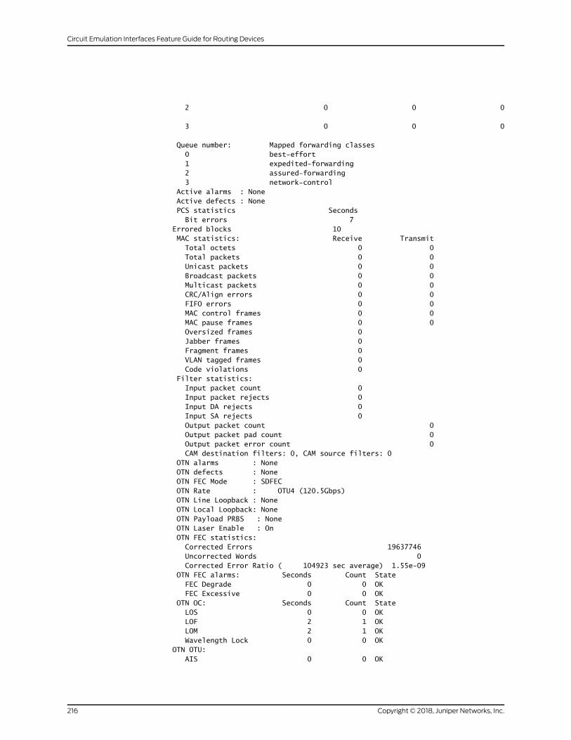
2 0 0 0
3 0 0 0
Queue number: Mapped forwarding classes 0 best-effort 1 expedited-forwarding 2 assured-forwarding 3 network-control Active alarms : None Active defects : None PCS statistics Seconds Bit errors 7 Errored blocks 10 MAC statistics: Receive Transmit Total octets 0 0 Total packets 0 0 Unicast packets 0 0 Broadcast packets 0 0 Multicast packets 0 0 CRC/Align errors 0 0 FIFO errors 0 0 MAC control frames 0 0 MAC pause frames 0 0 Oversized frames 0 Jabber frames 0 Fragment frames 0 VLAN tagged frames 0 Code violations 0 Filter statistics: Input packet count 0 Input packet rejects 0 Input DA rejects 0 Input SA rejects 0 Output packet count 0 Output packet pad count 0 Output packet error count 0 CAM destination filters: 0, CAM source filters: 0 OTN alarms : None OTN defects : None OTN FEC Mode : SDFEC OTN Rate : OTU4 (120.5Gbps) OTN Line Loopback : None OTN Local Loopback: None OTN Payload PRBS : None OTN Laser Enable : On OTN FEC statistics: Corrected Errors 19637746 Uncorrected Words 0 Corrected Error Ratio ( 104923 sec average) 1.55e-09 OTN FEC alarms: Seconds Count State FEC Degrade 0 0 OK FEC Excessive 0 0 OK OTN OC: Seconds Count State LOS 0 0 OK LOF 2 1 OK LOM 2 1 OK Wavelength Lock 0 0 OK OTN OTU: AIS 0 0 OK
Copyright © 2018, Juniper Networks, Inc.216
Circuit Emulation Interfaces Feature Guide for Routing Devices
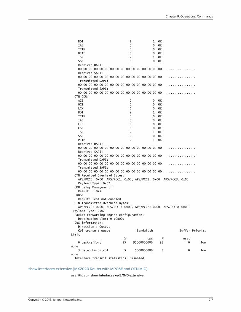
BDI 2 1 OK IAE 0 0 OK TTIM 0 0 OK BIAE 0 0 OK TSF 2 1 OK SSF 0 0 OK Received DAPI: 00 00 00 00 00 00 00 00 00 00 00 00 00 00 00 00 ................ Received SAPI: 00 00 00 00 00 00 00 00 00 00 00 00 00 00 00 00 ................ Transmitted DAPI: 00 00 00 00 00 00 00 00 00 00 00 00 00 00 00 00 ................ Transmitted SAPI: 00 00 00 00 00 00 00 00 00 00 00 00 00 00 00 00 ................ OTN ODU: AIS 0 0 OK OCI 0 0 OK LCK 0 0 OK BDI 2 1 OK TTIM 0 0 OK IAE 0 0 OK LTC 0 0 OK CSF 0 0 OK TSF 2 1 OK SSF 0 0 OK PTIM 2 1 OK Received DAPI: 00 00 00 00 00 00 00 00 00 00 00 00 00 00 00 00 ................ Received SAPI: 00 00 00 00 00 00 00 00 00 00 00 00 00 00 00 00 ................ Transmitted DAPI: 00 00 00 00 00 00 00 00 00 00 00 00 00 00 00 00 ................ Transmitted SAPI: 00 00 00 00 00 00 00 00 00 00 00 00 00 00 00 00 ................ OTN Received Overhead Bytes: APS/PCC0: 0x00, APS/PCC1: 0x00, APS/PCC2: 0x00, APS/PCC3: 0x00 Payload Type: 0x07 ODU Delay Management : Result : 0ms PRBS: Result: Test not enabled OTN Transmitted Overhead Bytes: APS/PCC0: 0x00, APS/PCC1: 0x00, APS/PCC2: 0x00, APS/PCC3: 0x00 Payload Type: 0x07 Packet Forwarding Engine configuration: Destination slot: 0 (0x00) CoS information: Direction : Output CoS transmit queue Bandwidth Buffer Priority Limit % bps % usec 0 best-effort 95 95000000000 95 0 low none 3 network-control 5 5000000000 5 0 low none Interface transmit statistics: Disabled
show interfaces extensive (MX2020 Router with MPC6E andOTNMIC)
user@host> show interfaces xe-3/0/0 extensive
217Copyright © 2018, Juniper Networks, Inc.
Chapter 9: Operational Commands
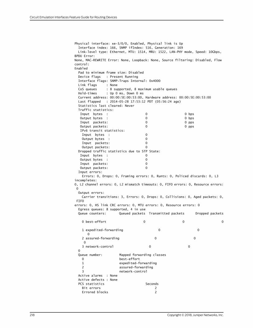
Physical interface: xe-3/0/0, Enabled, Physical link is Up Interface index: 166, SNMP ifIndex: 516, Generation: 169 Link-level type: Ethernet, MTU: 1514, MRU: 1522, LAN-PHY mode, Speed: 10Gbps, BPDU Error: None, MAC-REWRITE Error: None, Loopback: None, Source filtering: Disabled, Flow control: Enabled Pad to minimum frame size: Disabled Device flags : Present Running Interface flags: SNMP-Traps Internal: 0x4000 Link flags : None CoS queues : 8 supported, 8 maximum usable queues Hold-times : Up 0 ms, Down 0 ms Current address: 00:00:5E:00:53:00, Hardware address: 00:00:5E:00:53:00 Last flapped : 2014-05-28 17:53:12 PDT (05:56:24 ago) Statistics last cleared: Never Traffic statistics: Input bytes : 0 0 bps Output bytes : 0 0 bps Input packets: 0 0 pps Output packets: 0 0 pps IPv6 transit statistics: Input bytes : 0 Output bytes : 0 Input packets: 0 Output packets: 0 Dropped traffic statistics due to STP State: Input bytes : 0 Output bytes : 0 Input packets: 0 Output packets: 0 Input errors: Errors: 0, Drops: 0, Framing errors: 0, Runts: 0, Policed discards: 0, L3 incompletes: 0, L2 channel errors: 0, L2 mismatch timeouts: 0, FIFO errors: 0, Resource errors: 0 Output errors: Carrier transitions: 3, Errors: 0, Drops: 0, Collisions: 0, Aged packets: 0, FIFO errors: 0, HS link CRC errors: 0, MTU errors: 0, Resource errors: 0 Egress queues: 8 supported, 4 in use Queue counters: Queued packets Transmitted packets Dropped packets
0 best-effort 0 0 0
1 expedited-forwarding 0 0 0 2 assured-forwarding 0 0 0 3 network-control 0 0 0 Queue number: Mapped forwarding classes 0 best-effort 1 expedited-forwarding 2 assured-forwarding 3 network-control Active alarms : None Active defects : None PCS statistics Seconds Bit errors 2 Errored blocks 2
Copyright © 2018, Juniper Networks, Inc.218
Circuit Emulation Interfaces Feature Guide for Routing Devices
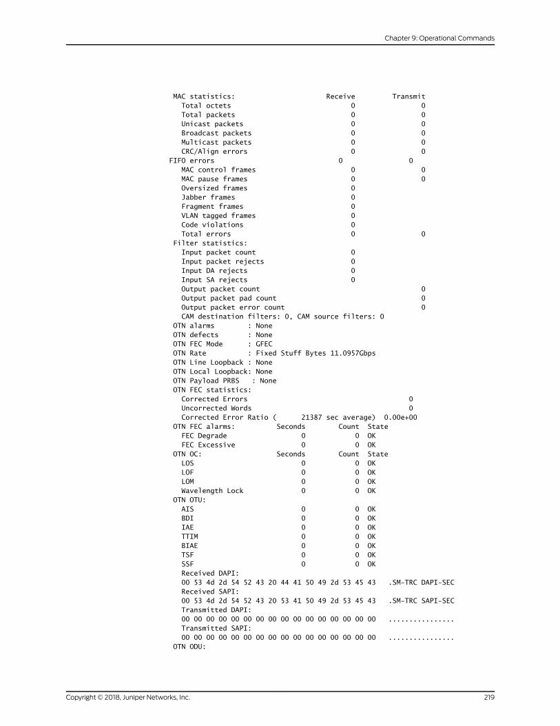
MAC statistics: Receive Transmit Total octets 0 0 Total packets 0 0 Unicast packets 0 0 Broadcast packets 0 0 Multicast packets 0 0 CRC/Align errors 0 0 FIFO errors 0 0 MAC control frames 0 0 MAC pause frames 0 0 Oversized frames 0 Jabber frames 0 Fragment frames 0 VLAN tagged frames 0 Code violations 0 Total errors 0 0 Filter statistics: Input packet count 0 Input packet rejects 0 Input DA rejects 0 Input SA rejects 0 Output packet count 0 Output packet pad count 0 Output packet error count 0 CAM destination filters: 0, CAM source filters: 0 OTN alarms : None OTN defects : None OTN FEC Mode : GFEC OTN Rate : Fixed Stuff Bytes 11.0957Gbps OTN Line Loopback : None OTN Local Loopback: None OTN Payload PRBS : None OTN FEC statistics: Corrected Errors 0 Uncorrected Words 0 Corrected Error Ratio ( 21387 sec average) 0.00e+00 OTN FEC alarms: Seconds Count State FEC Degrade 0 0 OK FEC Excessive 0 0 OK OTN OC: Seconds Count State LOS 0 0 OK LOF 0 0 OK LOM 0 0 OK Wavelength Lock 0 0 OK OTN OTU: AIS 0 0 OK BDI 0 0 OK IAE 0 0 OK TTIM 0 0 OK BIAE 0 0 OK TSF 0 0 OK SSF 0 0 OK Received DAPI: 00 53 4d 2d 54 52 43 20 44 41 50 49 2d 53 45 43 .SM-TRC DAPI-SEC Received SAPI: 00 53 4d 2d 54 52 43 20 53 41 50 49 2d 53 45 43 .SM-TRC SAPI-SEC Transmitted DAPI: 00 00 00 00 00 00 00 00 00 00 00 00 00 00 00 00 ................ Transmitted SAPI: 00 00 00 00 00 00 00 00 00 00 00 00 00 00 00 00 ................ OTN ODU:
219Copyright © 2018, Juniper Networks, Inc.
Chapter 9: Operational Commands
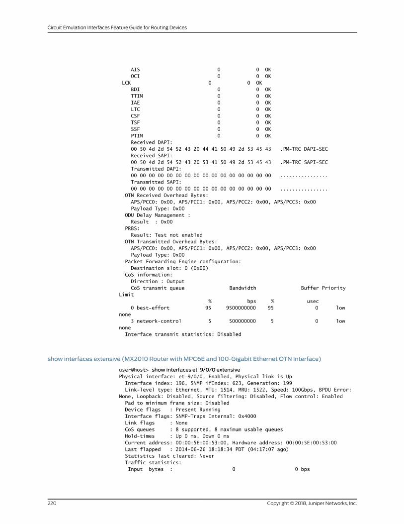
AIS 0 0 OK OCI 0 0 OK LCK 0 0 OK BDI 0 0 OK TTIM 0 0 OK IAE 0 0 OK LTC 0 0 OK CSF 0 0 OK TSF 0 0 OK SSF 0 0 OK PTIM 0 0 OK Received DAPI: 00 50 4d 2d 54 52 43 20 44 41 50 49 2d 53 45 43 .PM-TRC DAPI-SEC Received SAPI: 00 50 4d 2d 54 52 43 20 53 41 50 49 2d 53 45 43 .PM-TRC SAPI-SEC Transmitted DAPI: 00 00 00 00 00 00 00 00 00 00 00 00 00 00 00 00 ................ Transmitted SAPI: 00 00 00 00 00 00 00 00 00 00 00 00 00 00 00 00 ................ OTN Received Overhead Bytes: APS/PCC0: 0x00, APS/PCC1: 0x00, APS/PCC2: 0x00, APS/PCC3: 0x00 Payload Type: 0x00 ODU Delay Management : Result : 0x00 PRBS: Result: Test not enabled OTN Transmitted Overhead Bytes: APS/PCC0: 0x00, APS/PCC1: 0x00, APS/PCC2: 0x00, APS/PCC3: 0x00 Payload Type: 0x00 Packet Forwarding Engine configuration: Destination slot: 0 (0x00) CoS information: Direction : Output CoS transmit queue Bandwidth Buffer Priority Limit % bps % usec 0 best-effort 95 9500000000 95 0 low none 3 network-control 5 500000000 5 0 low none Interface transmit statistics: Disabled
show interfaces extensive (MX2010 Router with MPC6E and 100-Gigabit Ethernet OTN Interface)
user@host> show interfaces et-9/0/0 extensivePhysical interface: et-9/0/0, Enabled, Physical link is Up Interface index: 196, SNMP ifIndex: 623, Generation: 199 Link-level type: Ethernet, MTU: 1514, MRU: 1522, Speed: 100Gbps, BPDU Error: None, Loopback: Disabled, Source filtering: Disabled, Flow control: Enabled Pad to minimum frame size: Disabled Device flags : Present Running Interface flags: SNMP-Traps Internal: 0x4000 Link flags : None CoS queues : 8 supported, 8 maximum usable queues Hold-times : Up 0 ms, Down 0 ms Current address: 00:00:5E:00:53:00, Hardware address: 00:00:5E:00:53:00 Last flapped : 2014-06-26 18:18:34 PDT (04:17:07 ago) Statistics last cleared: Never Traffic statistics: Input bytes : 0 0 bps
Copyright © 2018, Juniper Networks, Inc.220
Circuit Emulation Interfaces Feature Guide for Routing Devices
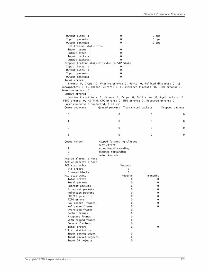
Output bytes : 0 0 bps Input packets: 0 0 pps Output packets: 0 0 pps IPv6 transit statistics: Input bytes : 0 Output bytes : 0 Input packets: 0 Output packets: 0 Dropped traffic statistics due to STP State: Input bytes : 0 Output bytes : 0 Input packets: 0 Output packets: 0 Input errors: Errors: 0, Drops: 0, Framing errors: 0, Runts: 0, Policed discards: 0, L3 incompletes: 0, L2 channel errors: 0, L2 mismatch timeouts: 0, FIFO errors: 0, Resource errors: 0 Output errors: Carrier transitions: 1, Errors: 0, Drops: 0, Collisions: 0, Aged packets: 0, FIFO errors: 0, HS link CRC errors: 0, MTU errors: 0, Resource errors: 0 Egress queues: 8 supported, 4 in use Queue counters: Queued packets Transmitted packets Dropped packets
0 0 0 0
1 0 0 0
2 0 0 0
3 0 0 0
Queue number: Mapped forwarding classes 0 best-effort 1 expedited-forwarding 2 assured-forwarding 3 network-control Active alarms : None Active defects : None PCS statistics Seconds Bit errors 0 Errored blocks 0 MAC statistics: Receive Transmit Total octets 0 0 Total packets 0 0 Unicast packets 0 0 Broadcast packets 0 0 Multicast packets 0 0 CRC/Align errors 0 0 FIFO errors 0 0 MAC control frames 0 0 MAC pause frames 0 0 Oversized frames 0 Jabber frames 0 Fragment frames 0 VLAN tagged frames 0 Code violations 0 Total errors 0 0 Filter statistics: Input packet count 0 Input packet rejects 0 Input DA rejects 0
221Copyright © 2018, Juniper Networks, Inc.
Chapter 9: Operational Commands
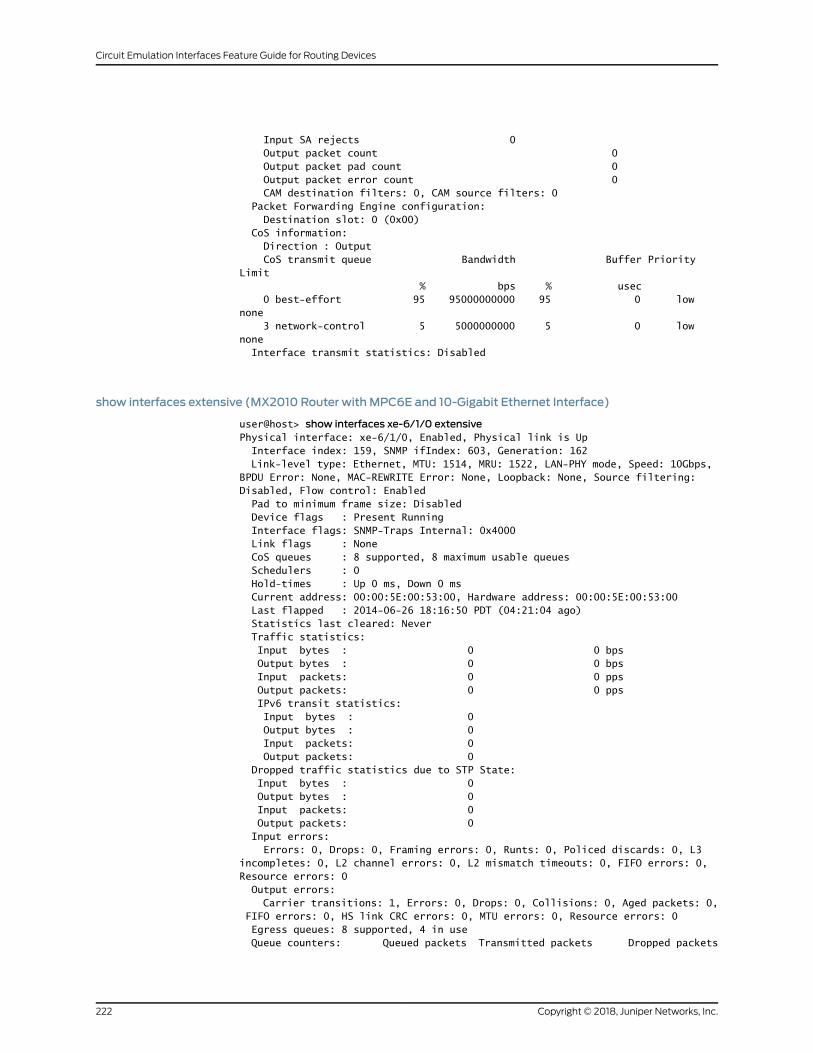
Input SA rejects 0 Output packet count 0 Output packet pad count 0 Output packet error count 0 CAM destination filters: 0, CAM source filters: 0 Packet Forwarding Engine configuration: Destination slot: 0 (0x00) CoS information: Direction : Output CoS transmit queue Bandwidth Buffer Priority Limit % bps % usec 0 best-effort 95 95000000000 95 0 low none 3 network-control 5 5000000000 5 0 low none Interface transmit statistics: Disabled
show interfaces extensive (MX2010 Router with MPC6E and 10-Gigabit Ethernet Interface)
user@host> show interfaces xe-6/1/0 extensivePhysical interface: xe-6/1/0, Enabled, Physical link is Up Interface index: 159, SNMP ifIndex: 603, Generation: 162 Link-level type: Ethernet, MTU: 1514, MRU: 1522, LAN-PHY mode, Speed: 10Gbps, BPDU Error: None, MAC-REWRITE Error: None, Loopback: None, Source filtering: Disabled, Flow control: Enabled Pad to minimum frame size: Disabled Device flags : Present Running Interface flags: SNMP-Traps Internal: 0x4000 Link flags : None CoS queues : 8 supported, 8 maximum usable queues Schedulers : 0 Hold-times : Up 0 ms, Down 0 ms Current address: 00:00:5E:00:53:00, Hardware address: 00:00:5E:00:53:00 Last flapped : 2014-06-26 18:16:50 PDT (04:21:04 ago) Statistics last cleared: Never Traffic statistics: Input bytes : 0 0 bps Output bytes : 0 0 bps Input packets: 0 0 pps Output packets: 0 0 pps IPv6 transit statistics: Input bytes : 0 Output bytes : 0 Input packets: 0 Output packets: 0 Dropped traffic statistics due to STP State: Input bytes : 0 Output bytes : 0 Input packets: 0 Output packets: 0 Input errors: Errors: 0, Drops: 0, Framing errors: 0, Runts: 0, Policed discards: 0, L3 incompletes: 0, L2 channel errors: 0, L2 mismatch timeouts: 0, FIFO errors: 0, Resource errors: 0 Output errors: Carrier transitions: 1, Errors: 0, Drops: 0, Collisions: 0, Aged packets: 0, FIFO errors: 0, HS link CRC errors: 0, MTU errors: 0, Resource errors: 0 Egress queues: 8 supported, 4 in use Queue counters: Queued packets Transmitted packets Dropped packets
Copyright © 2018, Juniper Networks, Inc.222
Circuit Emulation Interfaces Feature Guide for Routing Devices

0 0 0 0
1 0 0 0
2 0 0 0
3 0 0 0
Queue number: Mapped forwarding classes 0 best-effort 1 expedited-forwarding 2 assured-forwarding 3 network-control Active alarms : None Active defects : None PCS statistics Seconds Bit errors 0 Errored blocks 1 MAC statistics: Receive Transmit Total octets 0 0 Total packets 0 0 Unicast packets 0 0 Broadcast packets 0 0 Multicast packets 0 0 CRC/Align errors 0 0 FIFO errors 0 0 MAC control frames 0 0 MAC pause frames 0 0 Oversized frames 0 Jabber frames 0 Fragment frames 0 VLAN tagged frames 0 Code violations 0 Total errors 0 0 Filter statistics: Input packet count 0 Input packet rejects 0 Input DA rejects 0 Input SA rejects 0 Output packet count 0 Output packet pad count 0 Output packet error count 0 CAM destination filters: 0, CAM source filters: 0 Packet Forwarding Engine configuration: Destination slot: 0 (0x00) CoS information: Direction : Output CoS transmit queue Bandwidth Buffer Priority Limit % bps % usec 0 best-effort 95 9500000000 95 0 low none 3 network-control 5 500000000 5 0 low none Interface transmit statistics: Disabled
223Copyright © 2018, Juniper Networks, Inc.
Chapter 9: Operational Commands

show interfaces extensive (T4000 Routers with Type 5 FPCs)
The output fields for the show interfaces interface extensive command remains the same
for 12-port 10-Gigabit Ethernet LAN/WAN PIC with SFP+ (PF-12XGE-SFPP), 24-port
10-Gigabit Ethernet LAN/WAN PIC with SFP+ (PF-24XGE-SFPP), and 100-Gigabit
Ethernet Type 5 PIC with CFP (PF-1CGE-CFP).
user@host> show interfaces xe-4/0/0 extensivePhysical interface: xe-4/0/0, Enabled, Physical link is Up Interface index: 200, SNMP ifIndex: 592, Generation: 203 Link-level type: Ethernet, MTU: 1514, LAN-PHY mode, Speed: 10Gbps, BPDU Error: None, Loopback: None, Source filtering: Disabled, Flow control: Enabled Device flags : Present Running Interface flags: SNMP-Traps Internal: 0x4000 Link flags : None CoS queues : 8 supported, 8 maximum usable queues Hold-times : Up 0 ms, Down 0 ms Damping : half-life: 5 sec, max-suppress: 20 sec, reuse 1000, suppress: 2000, state: enabled Current address: 00:00:5E:00:53:00, Hardware address: 00:00:5E:00:53:00 Last flapped : 2013-06-03 16:01:56 PDT (06:04:07 ago) Statistics last cleared: Never Traffic statistics: Input bytes : 0 0 bps Output bytes : 0 0 bps Input packets: 0 0 pps Output packets: 0 0 pps IPv6 transit statistics: Input bytes : 0 Output bytes : 0 Input packets: 0 Output packets: 0 Input errors: Errors: 0, Drops: 0, Framing errors: 0, Runts: 0, Policed discards: 0, L3 incompletes: 0, L2 channel errors: 0, L2 mismatch timeouts: 0, FIFO errors: 0, Resource errors: 0 Output errors: Carrier transitions: 1, Errors: 0, Drops: 0, Collisions: 0, Aged packets: 0, FIFO errors: 0, HS link CRC errors: 0, MTU errors: 0, Resource errors: 0 Egress queues: 8 supported, 4 in use Queue counters: Queued packets Transmitted packets Dropped packets
0 best-effort 0 0 0
1 expedited-fo 0 0 0
2 assured-forw 0 0 0
3 network-cont 0 0 0
Queue number: Mapped forwarding classes 0 best-effort 1 expedited-forwarding 2 assured-forwarding 3 network-control Active alarms : None Active defects : None PCS statistics Seconds Bit errors 0 Errored blocks 0
Copyright © 2018, Juniper Networks, Inc.224
Circuit Emulation Interfaces Feature Guide for Routing Devices
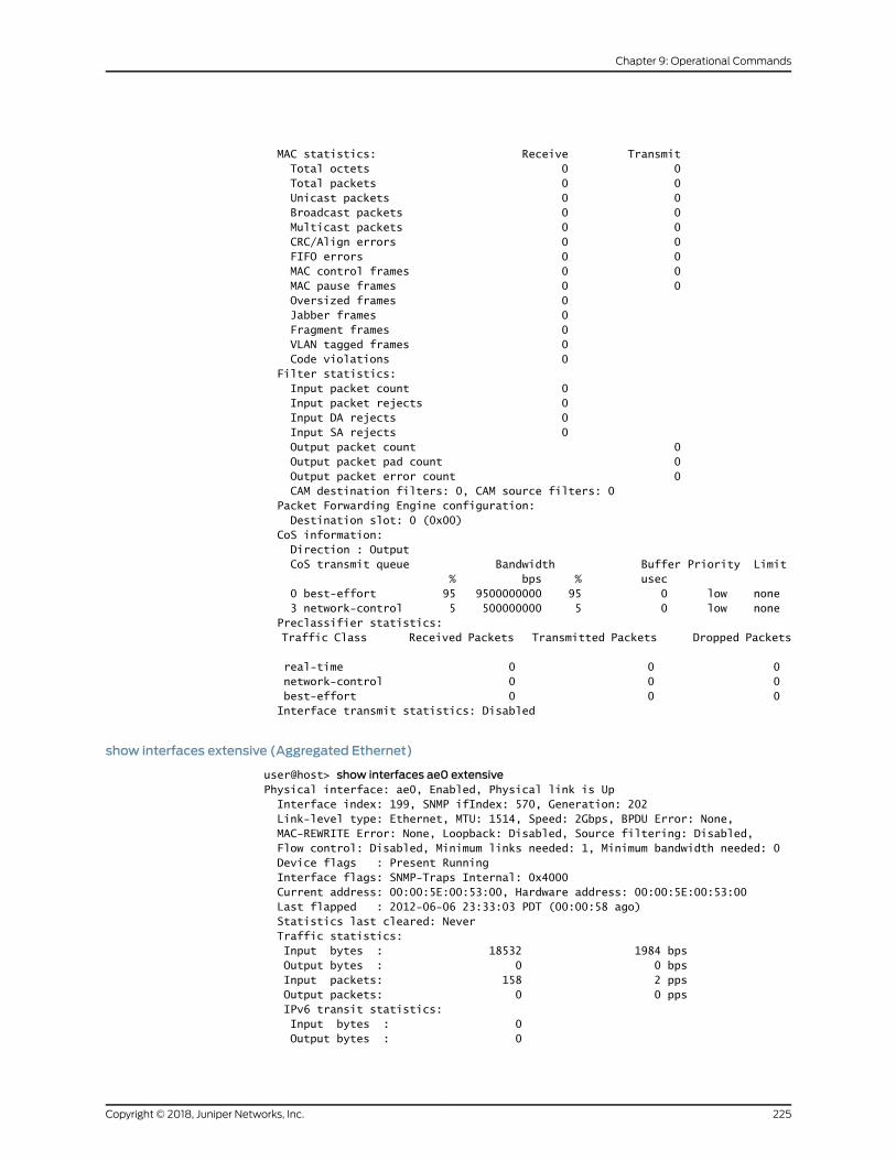
MAC statistics: Receive Transmit Total octets 0 0 Total packets 0 0 Unicast packets 0 0 Broadcast packets 0 0 Multicast packets 0 0 CRC/Align errors 0 0 FIFO errors 0 0 MAC control frames 0 0 MAC pause frames 0 0 Oversized frames 0 Jabber frames 0 Fragment frames 0 VLAN tagged frames 0 Code violations 0 Filter statistics: Input packet count 0 Input packet rejects 0 Input DA rejects 0 Input SA rejects 0 Output packet count 0 Output packet pad count 0 Output packet error count 0 CAM destination filters: 0, CAM source filters: 0 Packet Forwarding Engine configuration: Destination slot: 0 (0x00) CoS information: Direction : Output CoS transmit queue Bandwidth Buffer Priority Limit % bps % usec 0 best-effort 95 9500000000 95 0 low none 3 network-control 5 500000000 5 0 low none Preclassifier statistics: Traffic Class Received Packets Transmitted Packets Dropped Packets
real-time 0 0 0 network-control 0 0 0 best-effort 0 0 0 Interface transmit statistics: Disabled
show interfaces extensive (Aggregated Ethernet)
user@host> show interfaces ae0 extensivePhysical interface: ae0, Enabled, Physical link is Up Interface index: 199, SNMP ifIndex: 570, Generation: 202 Link-level type: Ethernet, MTU: 1514, Speed: 2Gbps, BPDU Error: None, MAC-REWRITE Error: None, Loopback: Disabled, Source filtering: Disabled, Flow control: Disabled, Minimum links needed: 1, Minimum bandwidth needed: 0 Device flags : Present Running Interface flags: SNMP-Traps Internal: 0x4000 Current address: 00:00:5E:00:53:00, Hardware address: 00:00:5E:00:53:00 Last flapped : 2012-06-06 23:33:03 PDT (00:00:58 ago) Statistics last cleared: Never Traffic statistics: Input bytes : 18532 1984 bps Output bytes : 0 0 bps Input packets: 158 2 pps Output packets: 0 0 pps IPv6 transit statistics: Input bytes : 0 Output bytes : 0
225Copyright © 2018, Juniper Networks, Inc.
Chapter 9: Operational Commands

Input packets: 0 Output packets: 0 Dropped traffic statistics due to STP State: Input bytes : 0 Output bytes : 0 Input packets: 0 Output packets: 0 Input errors: Errors: 0, Drops: 0, Framing errors: 0, Runts: 0, Giants: 0, Policed discards: 0, Resource errors: 0 Output errors: Carrier transitions: 0, Errors: 0, Drops: 0, MTU errors: 0, Resource errors: 0 Ingress queues: 8 supported, 4 in use Queue counters: Queued packets Transmitted packets Dropped packets
0 best-effort 0 0 0
1 expedited-fo 0 0 0
2 assured-forw 0 0 0
3 network-cont 0 0 0
Egress queues: 8 supported, 4 in use Queue counters: Queued packets Transmitted packets Dropped packets
0 best-effort 57 57 0
1 expedited-fo 0 0 0
2 assured-forw 0 0 0
3 network-cont 63605 63605 0
Queue number: Mapped forwarding classes 0 best-effort 1 expedited-forwarding 2 assured-forwarding 3 network-control
Logical interface ae0.0 (Index 331) (SNMP ifIndex 583) (Generation 142) Flags: SNMP-Traps 0x4004000 Encapsulation: ENET2 Statistics Packets pps Bytes bps Bundle: Input : 149 2 17416 1984 Output: 0 0 0 0 Link: ge-3/2/5.0 Input : 90 1 10100 992 Output: 0 0 0 0 ge-3/3/9.0 Input : 59 1 7316 992 Output: 0 0 0 0 LACP info: Role System System Port Port Port priority identifier priority number key ge-3/2/5.0 Actor 100 00:00:00:00:00:01 127 1 1
Copyright © 2018, Juniper Networks, Inc.226
Circuit Emulation Interfaces Feature Guide for Routing Devices
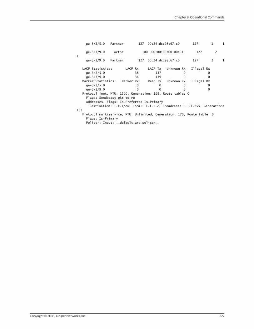
ge-3/2/5.0 Partner 127 00:24:dc:98:67:c0 127 1 1
ge-3/3/9.0 Actor 100 00:00:00:00:00:01 127 2 1 ge-3/3/9.0 Partner 127 00:24:dc:98:67:c0 127 2 1
LACP Statistics: LACP Rx LACP Tx Unknown Rx Illegal Rx ge-3/2/5.0 38 137 0 0 ge-3/3/9.0 36 139 0 0 Marker Statistics: Marker Rx Resp Tx Unknown Rx Illegal Rx ge-3/2/5.0 0 0 0 0 ge-3/3/9.0 0 0 0 0 Protocol inet, MTU: 1500, Generation: 169, Route table: 0 Flags: Sendbcast-pkt-to-re Addresses, Flags: Is-Preferred Is-Primary Destination: 1.1.1/24, Local: 1.1.1.2, Broadcast: 1.1.1.255, Generation: 153 Protocol multiservice, MTU: Unlimited, Generation: 170, Route table: 0 Flags: Is-Primary Policer: Input: __default_arp_policer__
227Copyright © 2018, Juniper Networks, Inc.
Chapter 9: Operational Commands

Copyright © 2018, Juniper Networks, Inc.228
Circuit Emulation Interfaces Feature Guide for Routing Devices