
Junos® OS ATM Interfaces Feature Guide for Routing Devices · 2019-03-21 ·...
404
Junos ® OS ATM Interfaces Feature Guide for Routing Devices Modified: 2019-03-21 Copyright © 2019, Juniper Networks, Inc.
Transcript of Junos® OS ATM Interfaces Feature Guide for Routing Devices · 2019-03-21 ·...

Junos®OS
ATM Interfaces Feature Guide for Routing Devices
Modified: 2019-03-21
Copyright © 2019, Juniper Networks, Inc.

Juniper Networks, Inc.1133 InnovationWaySunnyvale, California 94089USA408-745-2000www.juniper.net
Juniper Networks, the Juniper Networks logo, Juniper, and Junos are registered trademarks of Juniper Networks, Inc. in the United Statesand other countries. All other trademarks, service marks, registeredmarks, or registered service marks are the property of their respectiveowners.
Juniper Networks assumes no responsibility for any inaccuracies in this document. Juniper Networks reserves the right to change, modify,transfer, or otherwise revise this publication without notice.
Junos®OS ATM Interfaces Feature Guide for Routing Devices
Copyright © 2019 Juniper Networks, Inc. All rights reserved.
The information in this document is current as of the date on the title page.
YEAR 2000 NOTICE
Juniper Networks hardware and software products are Year 2000 compliant. Junos OS has no known time-related limitations through theyear 2038. However, the NTP application is known to have some difficulty in the year 2036.
ENDUSER LICENSE AGREEMENT
The Juniper Networks product that is the subject of this technical documentation consists of (or is intended for use with) Juniper Networkssoftware. Use of such software is subject to the terms and conditions of the End User License Agreement (“EULA”) posted athttps://support.juniper.net/support/eula/. By downloading, installing or using such software, you agree to the terms and conditions ofthat EULA.
Copyright © 2019, Juniper Networks, Inc.ii

Table of Contents
About the Documentation . . . . . . . . . . . . . . . . . . . . . . . . . . . . . . . . . . . . . . . . . . . . xv
Documentation and Release Notes . . . . . . . . . . . . . . . . . . . . . . . . . . . . . . . . . xv
Using the Examples in This Manual . . . . . . . . . . . . . . . . . . . . . . . . . . . . . . . . . xv
Merging a Full Example . . . . . . . . . . . . . . . . . . . . . . . . . . . . . . . . . . . . . . . xvi
Merging a Snippet . . . . . . . . . . . . . . . . . . . . . . . . . . . . . . . . . . . . . . . . . . . xvi
Documentation Conventions . . . . . . . . . . . . . . . . . . . . . . . . . . . . . . . . . . . . . xvii
Documentation Feedback . . . . . . . . . . . . . . . . . . . . . . . . . . . . . . . . . . . . . . . . xix
Requesting Technical Support . . . . . . . . . . . . . . . . . . . . . . . . . . . . . . . . . . . . . xix
Self-Help Online Tools and Resources . . . . . . . . . . . . . . . . . . . . . . . . . . . xx
Creating a Service Request with JTAC . . . . . . . . . . . . . . . . . . . . . . . . . . . . xx
Part 1 ATM Interfaces
Chapter 1 ATM Interfaces Overview . . . . . . . . . . . . . . . . . . . . . . . . . . . . . . . . . . . . . . . . . . . . 3
ATM Interfaces Overview . . . . . . . . . . . . . . . . . . . . . . . . . . . . . . . . . . . . . . . . . . . . . . 3
ATM Pseudowire Overview . . . . . . . . . . . . . . . . . . . . . . . . . . . . . . . . . . . . . . . . . . . . 5
Understanding Inverse Multiplexing for ATM . . . . . . . . . . . . . . . . . . . . . . . . . . . . . . . 5
Understanding Asynchronous Transfer Mode . . . . . . . . . . . . . . . . . . . . . . . . . . 6
Understanding Inverse Multiplexing for ATM . . . . . . . . . . . . . . . . . . . . . . . . . . . 6
How Inverse Multiplexing for ATMWorks . . . . . . . . . . . . . . . . . . . . . . . . . . . . . . 6
Supported Platforms . . . . . . . . . . . . . . . . . . . . . . . . . . . . . . . . . . . . . . . . . . . . . 8
Understanding ATM IMA Configuration on ACX Series Router . . . . . . . . . . . . . . . . . 9
IMA Version . . . . . . . . . . . . . . . . . . . . . . . . . . . . . . . . . . . . . . . . . . . . . . . . . . . . 10
IMA Frame Length . . . . . . . . . . . . . . . . . . . . . . . . . . . . . . . . . . . . . . . . . . . . . . . 10
Transmit Clock . . . . . . . . . . . . . . . . . . . . . . . . . . . . . . . . . . . . . . . . . . . . . . . . . . 10
IMA Group Symmetry . . . . . . . . . . . . . . . . . . . . . . . . . . . . . . . . . . . . . . . . . . . . 10
Minimum Active Links . . . . . . . . . . . . . . . . . . . . . . . . . . . . . . . . . . . . . . . . . . . . . 11
State Transition Variables: Alpha, Beta, and Gamma . . . . . . . . . . . . . . . . . . . . 11
IMA Link Addition and Deletion . . . . . . . . . . . . . . . . . . . . . . . . . . . . . . . . . . . . . 11
IMA Test Pattern Procedure . . . . . . . . . . . . . . . . . . . . . . . . . . . . . . . . . . . . . . . . 12
IMA Group Alarms and Group Defects . . . . . . . . . . . . . . . . . . . . . . . . . . . . . . . 12
IMA Link Alarms and Link Defects . . . . . . . . . . . . . . . . . . . . . . . . . . . . . . . . . . . 13
IMA Group Statistics . . . . . . . . . . . . . . . . . . . . . . . . . . . . . . . . . . . . . . . . . . . . . 14
IMA Link Statistics . . . . . . . . . . . . . . . . . . . . . . . . . . . . . . . . . . . . . . . . . . . . . . . 15
IMA Clocking . . . . . . . . . . . . . . . . . . . . . . . . . . . . . . . . . . . . . . . . . . . . . . . . . . . 16
Differential Delay . . . . . . . . . . . . . . . . . . . . . . . . . . . . . . . . . . . . . . . . . . . . . . . . 16
Understanding CoS on ATM IMA Pseudowire Interfaces Overview . . . . . . . . . . . . 16
Cell-Based ATM Policing . . . . . . . . . . . . . . . . . . . . . . . . . . . . . . . . . . . . . . . . . . 17
Cell-Based ATM Shaping . . . . . . . . . . . . . . . . . . . . . . . . . . . . . . . . . . . . . . . . . . 17
Fixed Classification . . . . . . . . . . . . . . . . . . . . . . . . . . . . . . . . . . . . . . . . . . . . . . 18
Supported Features on ATM1 and ATM2 IQ Interfaces . . . . . . . . . . . . . . . . . . . . . . 18
iiiCopyright © 2019, Juniper Networks, Inc.
ATM OAM F4 and F5 Cells on ACX Series Routers . . . . . . . . . . . . . . . . . . . . . . . . . 23
Chapter 2 Configuring ATM Interfaces . . . . . . . . . . . . . . . . . . . . . . . . . . . . . . . . . . . . . . . . . 27
Configuring Inverse Multiplexing for ATM (IMA) on ACX Series . . . . . . . . . . . . . . . 28
Example: ATM Pseudowire Base Configuration . . . . . . . . . . . . . . . . . . . . . . . . . . . 32
Example: Configuring ATM1 Interfaces . . . . . . . . . . . . . . . . . . . . . . . . . . . . . . . . . . 36
Example: Configuring ATM2 IQ Interfaces . . . . . . . . . . . . . . . . . . . . . . . . . . . . . . . . 38
Configuring the ATM PIC Type . . . . . . . . . . . . . . . . . . . . . . . . . . . . . . . . . . . . . . . . . 39
Configuring ATM Cell-Relay Promiscuous Mode . . . . . . . . . . . . . . . . . . . . . . . . . . 42
Configuring the Maximum Number of ATM1 VCs on a VP . . . . . . . . . . . . . . . . . . . 46
Configuring Communication with Directly Attached ATM Switches and
Routers . . . . . . . . . . . . . . . . . . . . . . . . . . . . . . . . . . . . . . . . . . . . . . . . . . . . . . . 47
Enabling ILMI for Cell Relay . . . . . . . . . . . . . . . . . . . . . . . . . . . . . . . . . . . . . . . . . . . 48
Configuring E3 and T3 Parameters on ATM Interfaces . . . . . . . . . . . . . . . . . . . . . . 49
Configuring SONET/SDH Parameters on ATM Interfaces . . . . . . . . . . . . . . . . . . . 50
Configuring ATM Interface Encapsulation . . . . . . . . . . . . . . . . . . . . . . . . . . . . . . . . 51
Configuring Layer 2 Circuit Transport Mode . . . . . . . . . . . . . . . . . . . . . . . . . . . . . . 54
Layer 2 Circuit Transport Mode on ATMMICs Overview . . . . . . . . . . . . . . . . . . . . . 63
Configuring Layer 2 Circuit Transport Mode on ATM MICs . . . . . . . . . . . . . . . . . . . 64
Example: Configuring Layer 2 Circuit Transport Mode on ATMMICs . . . . . . . . . . . 65
Configuring a Point-to-Multipoint Connection on ATMMICs . . . . . . . . . . . . . . . . . 68
Configuring ATM Cell-Relay Pseudowire . . . . . . . . . . . . . . . . . . . . . . . . . . . . . . . . . 71
Configuring ATM Cell-Relay Pseudowire in Port-Promiscuous Mode . . . . . . . 71
Configuring ATM Cell-Relay Pseudowire in VP-Promiscuous Mode . . . . . . . . 72
Configuring ATM Cell-Relay Pseudowire in VCC Mode . . . . . . . . . . . . . . . . . . 73
Configuring the Layer 2 Circuit Cell-Relay Cell Maximum Overview . . . . . . . . . . . 74
Class-Based Cell Bundling . . . . . . . . . . . . . . . . . . . . . . . . . . . . . . . . . . . . . . . . 75
Configuring Layer 2 Circuit Trunk Mode Scheduling Overview . . . . . . . . . . . . . . . . 76
Configuring CoS Queues in Layer 2 Circuit Trunk Mode . . . . . . . . . . . . . . . . . . . . . . 77
Configuring the Timeout for Bundling of Layer 2 Circuit Cell-Relay Cells . . . . . . . 79
Configuring an ATM1 Cell-Relay Circuit Overview . . . . . . . . . . . . . . . . . . . . . . . . . . 80
Example: Configuring an ATM1 Cell-Relay Circuit . . . . . . . . . . . . . . . . . . . . . . 80
Configuring an Individual VC on a Logical Interface . . . . . . . . . . . . . . . . . 81
Configuring Non-promiscuous port mode . . . . . . . . . . . . . . . . . . . . . . . . . 81
Configuring Nonpromiscuous VPI Mode . . . . . . . . . . . . . . . . . . . . . . . . . . 81
Configuring Nonpromiscuous VCI Mode . . . . . . . . . . . . . . . . . . . . . . . . . . 82
Configuring PPP over ATM2 Encapsulation Overview . . . . . . . . . . . . . . . . . . . . . . 82
Example: Configuring PPP over ATM2 IQ Encapsulation . . . . . . . . . . . . . . . . 83
Configuring Multilink PPP over ATM2 IQ Encapsulation . . . . . . . . . . . . . . . . . 84
Configuring a Multicast-Capable ATM1 or ATM2 IQ Connection . . . . . . . . . . . . . . 86
Configuring the ATM OAM F5 Loopback Cell Threshold . . . . . . . . . . . . . . . . . . . . 86
Configuring the OAM F4 Cell Flows . . . . . . . . . . . . . . . . . . . . . . . . . . . . . . . . . . . . . 86
Defining the ATM OAM F5 Loopback Cell Period . . . . . . . . . . . . . . . . . . . . . . . . . . 88
Configuring Fixed Classification on an ATM IMA Pseudowire . . . . . . . . . . . . . . . . 89
Example: Configuring Fixed Classification on an ATM IMA Pseudowire . . . . . . . . 90
Configuring Shaping on an ATM IMA Pseudowire . . . . . . . . . . . . . . . . . . . . . . . . . . 93
Copyright © 2019, Juniper Networks, Inc.iv
ATM Interfaces Feature Guide for Routing Devices

Example: Configuring Shaping on an ATM IMA Pseudowire . . . . . . . . . . . . . . . . . 95
Configuring Policing on an ATM IMA Pseudowire . . . . . . . . . . . . . . . . . . . . . . . . . . 99
Configuring an Input Policer . . . . . . . . . . . . . . . . . . . . . . . . . . . . . . . . . . . . . . 100
Configuring the ATM IMA Interface . . . . . . . . . . . . . . . . . . . . . . . . . . . . . . . . . 101
Example: Configuring Policing on an ATM IMA Pseudowire . . . . . . . . . . . . . . . . . 102
Defining the ATM Traffic-Shaping Profile Overview . . . . . . . . . . . . . . . . . . . . . . . 107
Configuring ATM CBR . . . . . . . . . . . . . . . . . . . . . . . . . . . . . . . . . . . . . . . . . . . 108
Configuring ATM2 IQ Real-Time VBR . . . . . . . . . . . . . . . . . . . . . . . . . . . . . . . 109
Configuring ATM VBR . . . . . . . . . . . . . . . . . . . . . . . . . . . . . . . . . . . . . . . . . . . 109
Specifying ATM1 Shaping Values . . . . . . . . . . . . . . . . . . . . . . . . . . . . . . . . . . . 110
Example: Specifying ATM1 Shaping Values . . . . . . . . . . . . . . . . . . . . . . . 112
Specifying ATM2 IQ Shaping Values . . . . . . . . . . . . . . . . . . . . . . . . . . . . . . . . 113
Defining Virtual Path Tunnels . . . . . . . . . . . . . . . . . . . . . . . . . . . . . . . . . . . . . . . . . 113
Configuring the ATM1 Queue Length . . . . . . . . . . . . . . . . . . . . . . . . . . . . . . . . . . . . 114
Configuring a Point-to-Point ATM1 or ATM2 IQ Connection . . . . . . . . . . . . . . . . . . 115
Configuring a Point-to-Multipoint ATM1 or ATM2 IQ Connection . . . . . . . . . . . . . 116
Configuring Inverse ATM1 or ATM2 ARP . . . . . . . . . . . . . . . . . . . . . . . . . . . . . . . . . 117
ATM2 IQ VC Tunnel CoS Components Overview . . . . . . . . . . . . . . . . . . . . . . . . . . 117
Configuring ATM2 IQ VC Tunnel CoS Components . . . . . . . . . . . . . . . . . . . . . 118
Configuring Linear RED Profiles . . . . . . . . . . . . . . . . . . . . . . . . . . . . . . . . . . . . 118
Configuring an ATM Scheduler Map . . . . . . . . . . . . . . . . . . . . . . . . . . . . . . . . 119
Enabling Eight Queues on ATM2 IQ Interfaces . . . . . . . . . . . . . . . . . . . . . . . . 121
Example: Enabling Eight Queues on T Series, M120, and M320 Routers . . . . 122
Configuring VC CoS Mode . . . . . . . . . . . . . . . . . . . . . . . . . . . . . . . . . . . . . . . . 126
Enabling the PLP Setting to Be Copied to the CLP Bit . . . . . . . . . . . . . . . . . . 127
Configuring ATM CoS on the Logical Interface . . . . . . . . . . . . . . . . . . . . . . . . 127
Example: Configuring ATM2 IQ VC Tunnel CoS Components . . . . . . . . . . . . 128
Configuring ATM Scheduler on Ethernet VPLS over a Bridged ATM Interface . . . 129
Example: Configuring ATM Scheduler Map on Ethernet VPLS over Bridged ATM
Interfaces . . . . . . . . . . . . . . . . . . . . . . . . . . . . . . . . . . . . . . . . . . . . . . . . . . . . . 130
Configuring the ATM2 IQ EPD Threshold . . . . . . . . . . . . . . . . . . . . . . . . . . . . . . . . 131
Example: Configuring the EPD Threshold for a Point-to-point ATM2
Interface . . . . . . . . . . . . . . . . . . . . . . . . . . . . . . . . . . . . . . . . . . . . . . . . . . 132
Example: Configuring the EPD Threshold for a Point-to-multipoint ATM2
Interface . . . . . . . . . . . . . . . . . . . . . . . . . . . . . . . . . . . . . . . . . . . . . . . . . . 132
Configuring Two EPD Thresholds per Queue . . . . . . . . . . . . . . . . . . . . . . . . . . . . . 133
Configuring the ATM2 IQ Transmission Weight . . . . . . . . . . . . . . . . . . . . . . . . . . . 133
Configuring the Junos OS to Enable ATM2 Intelligent Queuing Layer 2 Circuit
Transport Mode . . . . . . . . . . . . . . . . . . . . . . . . . . . . . . . . . . . . . . . . . . . . . . . . 134
Configuring the Junos OS to Enable Idle Cell Format and Payload Patterns for
ATM Devices . . . . . . . . . . . . . . . . . . . . . . . . . . . . . . . . . . . . . . . . . . . . . . . . . . . 135
Configuring the Junos OS to Use ATM Cell-Relay Accumulation Mode on an
ATM1 PIC . . . . . . . . . . . . . . . . . . . . . . . . . . . . . . . . . . . . . . . . . . . . . . . . . . . . . 136
Configuring the Junos OS to Support ILMI for Cell Relay Encapsulation on an
ATM2 IQ PIC . . . . . . . . . . . . . . . . . . . . . . . . . . . . . . . . . . . . . . . . . . . . . . . . . . . 137
Chapter 3 Configuring Passive Monitoring on ATM Interfaces . . . . . . . . . . . . . . . . . . . . 139
Enabling Passive Monitoring on ATM Interfaces . . . . . . . . . . . . . . . . . . . . . . . . . . 139
Removing MPLS Labels from Incoming Packets . . . . . . . . . . . . . . . . . . . . . . . . . . 140
vCopyright © 2019, Juniper Networks, Inc.
Table of Contents

Part 2 ATM-over-ADSL Interfaces
Chapter 4 ATM-over-ADSL Interfaces Overview . . . . . . . . . . . . . . . . . . . . . . . . . . . . . . . 145
ATM-over-ADSL Overview . . . . . . . . . . . . . . . . . . . . . . . . . . . . . . . . . . . . . . . . . . . 145
Chapter 5 Configuring ATM-over-ADSL Interfaces . . . . . . . . . . . . . . . . . . . . . . . . . . . . . 147
Configuring Physical ATM Interfaces and Logical Interface Properties for
ADSL . . . . . . . . . . . . . . . . . . . . . . . . . . . . . . . . . . . . . . . . . . . . . . . . . . . . . . . . . 147
Configuring the ATM-over-ADSL Virtual Path Identifier . . . . . . . . . . . . . . . . . . . . 148
Configuring the ATM-over-ADSL Physical Interface Operating Mode . . . . . . . . . 148
Configuring the ATM-over-ADSL Physical Interface Encapsulation Type . . . . . . 149
Configuring the ATM-over-ADSL Logical Interface Encapsulation Type . . . . . . . 150
Configuring the ATM-over-ADSL Protocol Family . . . . . . . . . . . . . . . . . . . . . . . . . 151
Configuring the ATM-over-ADSL Virtual Channel Identifier . . . . . . . . . . . . . . . . . . 151
Part 3 ATM-over-SHDSL Interfaces
Chapter 6 Configuring ATM-over-SHDSL Interfaces . . . . . . . . . . . . . . . . . . . . . . . . . . . . 155
Configuring ATM Mode for SHDSL Overview . . . . . . . . . . . . . . . . . . . . . . . . . . . . . 155
Configuring ATM Mode on the PIM . . . . . . . . . . . . . . . . . . . . . . . . . . . . . . . . . . . . . 157
Configuring SHDSL Operating Mode on an ATM Physical Interface . . . . . . . . . . . 157
Configuring Encapsulation on the ATM Physical Interface . . . . . . . . . . . . . . . . . . 158
Configuring Logical Interface Properties . . . . . . . . . . . . . . . . . . . . . . . . . . . . . . . . 158
Example: Configuring an ATM-over-SHDSL Interface . . . . . . . . . . . . . . . . . . . . . 160
Verifying an ATM-over-SHDSL Interface Configuration . . . . . . . . . . . . . . . . . . . . . 161
Part 4 Troubleshooting Information
Chapter 7 Monitoring and Troubleshooting ATM Interfaces . . . . . . . . . . . . . . . . . . . . . 165
Determining ATM Interface Type . . . . . . . . . . . . . . . . . . . . . . . . . . . . . . . . . . . . . . 165
Checklist for Determining ATM Interface Type . . . . . . . . . . . . . . . . . . . . . . . . 165
Determining the ATM Interface Type and Configuration . . . . . . . . . . . . . . . . 167
Determining the ATM Interface Type . . . . . . . . . . . . . . . . . . . . . . . . . . . . . . . . 167
Identifying the ATM Interface Type . . . . . . . . . . . . . . . . . . . . . . . . . . . . . . . . . 168
Verifying the ATM Configuration . . . . . . . . . . . . . . . . . . . . . . . . . . . . . . . . . . . 169
Verifying the Configuration of an ATM1 Interface . . . . . . . . . . . . . . . . . . 170
Verifying the Configuration of an ATM2 IQ Interface . . . . . . . . . . . . . . . . 171
Verifying the Configuration of an ATMMIC Interface . . . . . . . . . . . . . . . . 172
Examples of Incorrect Configurations of ATM Options . . . . . . . . . . . . . . . . . 173
Verifying the Configuration of the VCI on an ATM1 Interface . . . . . . . . . . 173
Verifying the Configuration of the VCI on an ATM2 IQ Interface . . . . . . . 174
Verifying the Configuration of Promiscuous Mode on an ATM2 IQ
Interface . . . . . . . . . . . . . . . . . . . . . . . . . . . . . . . . . . . . . . . . . . . . . . . 176
Monitoring ATM Interfaces . . . . . . . . . . . . . . . . . . . . . . . . . . . . . . . . . . . . . . . . . . . 178
Checklist for Monitoring ATM Interfaces . . . . . . . . . . . . . . . . . . . . . . . . . . . . . 178
Monitoring ATM Interfaces . . . . . . . . . . . . . . . . . . . . . . . . . . . . . . . . . . . . . . . 179
Monitoring ATM1 Interfaces . . . . . . . . . . . . . . . . . . . . . . . . . . . . . . . . . . . . . . . 180
Displaying the Status of a Specific ATM1 Interface . . . . . . . . . . . . . . . . . 180
Displaying Extensive Status Information for a Specific ATM1
Interface . . . . . . . . . . . . . . . . . . . . . . . . . . . . . . . . . . . . . . . . . . . . . . . 181
Copyright © 2019, Juniper Networks, Inc.vi
ATM Interfaces Feature Guide for Routing Devices

Monitoring Statistics for an ATM1 Interface . . . . . . . . . . . . . . . . . . . . . . . 183
Monitoring ATM2 IQ Interfaces . . . . . . . . . . . . . . . . . . . . . . . . . . . . . . . . . . . . 185
Displaying the Status of a Specific ATM2 IQ Interface . . . . . . . . . . . . . . 185
Displaying Extensive Information for a Specific ATM2 Interface . . . . . . . 187
Monitoring Statistics for an ATM2 Interface . . . . . . . . . . . . . . . . . . . . . . 193
Monitoring ATMMIC Interfaces . . . . . . . . . . . . . . . . . . . . . . . . . . . . . . . . . . . . 194
Displaying the Status of a Specific ATMMIC Interface . . . . . . . . . . . . . . 194
Displaying Extensive Information for a Specific ATMMIC Interface . . . . 196
Monitoring Traffic and Error Statistics for an ATM MIC Interface . . . . . 200
Configuring Interface Diagnostics Tools to Test the Physical Layer
Connections . . . . . . . . . . . . . . . . . . . . . . . . . . . . . . . . . . . . . . . . . . . . . . . . . . . 201
Configuring Loopback Testing . . . . . . . . . . . . . . . . . . . . . . . . . . . . . . . . . . . . . 201
Configuring BERT Testing . . . . . . . . . . . . . . . . . . . . . . . . . . . . . . . . . . . . . . . . 203
Starting and Stopping a BERT Test . . . . . . . . . . . . . . . . . . . . . . . . . . . . . . . . 207
Investigating Interface Steps and Commands for ATM Interfaces . . . . . . . . . . . 208
Using Loopback Testing for ATM Interfaces . . . . . . . . . . . . . . . . . . . . . . . . . . . . . 208
Checklist for Using Loopback Testing for ATM Interfaces . . . . . . . . . . . . . . . 208
Diagnosing a Suspected Hardware Problemwith an ATM1 or ATM2 IQ
Interface . . . . . . . . . . . . . . . . . . . . . . . . . . . . . . . . . . . . . . . . . . . . . . . . . . 210
Creating a Loopback . . . . . . . . . . . . . . . . . . . . . . . . . . . . . . . . . . . . . . . . . . . . 210
Creating a Physical Loopback . . . . . . . . . . . . . . . . . . . . . . . . . . . . . . . . . . 211
Configuring a Local Loopback . . . . . . . . . . . . . . . . . . . . . . . . . . . . . . . . . . 211
Setting Clocking to Internal . . . . . . . . . . . . . . . . . . . . . . . . . . . . . . . . . . . . . . . 213
Verifying That the ATM Interface Is Up . . . . . . . . . . . . . . . . . . . . . . . . . . . . . . 214
Clearing ATM Interface Statistics . . . . . . . . . . . . . . . . . . . . . . . . . . . . . . . . . . 217
Pinging the ATM Interface . . . . . . . . . . . . . . . . . . . . . . . . . . . . . . . . . . . . . . . . 217
Checking for ATM Interface Error Statistics . . . . . . . . . . . . . . . . . . . . . . . . . . 218
Diagnosing a Suspected Circuit Problem . . . . . . . . . . . . . . . . . . . . . . . . . . . . 222
Creating a Loop from the Router to the Network . . . . . . . . . . . . . . . . . . 223
Creating a Loop to the Router from Various Points in the Network . . . . 224
Locating ATM Alarms and Errors . . . . . . . . . . . . . . . . . . . . . . . . . . . . . . . . . . . . . . 224
List of Common ATM Alarms and Error . . . . . . . . . . . . . . . . . . . . . . . . . . . . . 225
Displaying ATM1 and ATM2 Alarms and Errors . . . . . . . . . . . . . . . . . . . . . . . . 225
Part 5 Configuration Statements and Operational Commands
Chapter 8 Configuration Statements . . . . . . . . . . . . . . . . . . . . . . . . . . . . . . . . . . . . . . . . 235
advertise-interval . . . . . . . . . . . . . . . . . . . . . . . . . . . . . . . . . . . . . . . . . . . . . . . . . . 237
allow-any-vci . . . . . . . . . . . . . . . . . . . . . . . . . . . . . . . . . . . . . . . . . . . . . . . . . . . . . 238
annex . . . . . . . . . . . . . . . . . . . . . . . . . . . . . . . . . . . . . . . . . . . . . . . . . . . . . . . . . . . 238
aps . . . . . . . . . . . . . . . . . . . . . . . . . . . . . . . . . . . . . . . . . . . . . . . . . . . . . . . . . . . . . 239
atm-encapsulation . . . . . . . . . . . . . . . . . . . . . . . . . . . . . . . . . . . . . . . . . . . . . . . . 240
atm-options . . . . . . . . . . . . . . . . . . . . . . . . . . . . . . . . . . . . . . . . . . . . . . . . . . . . . . 241
atm-scheduler-map . . . . . . . . . . . . . . . . . . . . . . . . . . . . . . . . . . . . . . . . . . . . . . . 242
authentication-key . . . . . . . . . . . . . . . . . . . . . . . . . . . . . . . . . . . . . . . . . . . . . . . . . 243
buildout (E3 or T3 over ATM Interfaces) . . . . . . . . . . . . . . . . . . . . . . . . . . . . . . . . 244
bytes . . . . . . . . . . . . . . . . . . . . . . . . . . . . . . . . . . . . . . . . . . . . . . . . . . . . . . . . . . . . 245
cbit-parity . . . . . . . . . . . . . . . . . . . . . . . . . . . . . . . . . . . . . . . . . . . . . . . . . . . . . . . . 246
cbr . . . . . . . . . . . . . . . . . . . . . . . . . . . . . . . . . . . . . . . . . . . . . . . . . . . . . . . . . . . . . . 247
viiCopyright © 2019, Juniper Networks, Inc.
Table of Contents

cell-bundle-size . . . . . . . . . . . . . . . . . . . . . . . . . . . . . . . . . . . . . . . . . . . . . . . . . . . 248
down-count . . . . . . . . . . . . . . . . . . . . . . . . . . . . . . . . . . . . . . . . . . . . . . . . . . . . . . 249
e3-options . . . . . . . . . . . . . . . . . . . . . . . . . . . . . . . . . . . . . . . . . . . . . . . . . . . . . . . 250
encapsulation (Logical Interface) . . . . . . . . . . . . . . . . . . . . . . . . . . . . . . . . . . . . . 251
encapsulation . . . . . . . . . . . . . . . . . . . . . . . . . . . . . . . . . . . . . . . . . . . . . . . . . . . . . 255
epd-threshold (Logical Interface) . . . . . . . . . . . . . . . . . . . . . . . . . . . . . . . . . . . . . 263
epd-threshold (Physical Interface) . . . . . . . . . . . . . . . . . . . . . . . . . . . . . . . . . . . . 264
family . . . . . . . . . . . . . . . . . . . . . . . . . . . . . . . . . . . . . . . . . . . . . . . . . . . . . . . . . . . 265
fast-aps-switch . . . . . . . . . . . . . . . . . . . . . . . . . . . . . . . . . . . . . . . . . . . . . . . . . . . 270
force . . . . . . . . . . . . . . . . . . . . . . . . . . . . . . . . . . . . . . . . . . . . . . . . . . . . . . . . . . . . . 271
forwarding-class (ATM2 IQ Scheduler Maps) . . . . . . . . . . . . . . . . . . . . . . . . . . . . 272
framing (E1, E3, and T1 Interfaces) . . . . . . . . . . . . . . . . . . . . . . . . . . . . . . . . . . . . . 273
high-plp-max-threshold . . . . . . . . . . . . . . . . . . . . . . . . . . . . . . . . . . . . . . . . . . . . 274
high-plp-threshold . . . . . . . . . . . . . . . . . . . . . . . . . . . . . . . . . . . . . . . . . . . . . . . . . 275
hold-time (APS) . . . . . . . . . . . . . . . . . . . . . . . . . . . . . . . . . . . . . . . . . . . . . . . . . . . 276
hold-time (SONET/SDH Defect Triggers) . . . . . . . . . . . . . . . . . . . . . . . . . . . . . . . 277
ilmi . . . . . . . . . . . . . . . . . . . . . . . . . . . . . . . . . . . . . . . . . . . . . . . . . . . . . . . . . . . . . 278
inverse-arp . . . . . . . . . . . . . . . . . . . . . . . . . . . . . . . . . . . . . . . . . . . . . . . . . . . . . . . 279
linear-red-profile . . . . . . . . . . . . . . . . . . . . . . . . . . . . . . . . . . . . . . . . . . . . . . . . . . 280
linear-red-profiles . . . . . . . . . . . . . . . . . . . . . . . . . . . . . . . . . . . . . . . . . . . . . . . . . . 281
lockout . . . . . . . . . . . . . . . . . . . . . . . . . . . . . . . . . . . . . . . . . . . . . . . . . . . . . . . . . . 282
loopback (ADSL, DS0, E1/E3, SONET/SDH, SHDSL, and T1/T3) . . . . . . . . . . . . 283
low-plp-max-threshold . . . . . . . . . . . . . . . . . . . . . . . . . . . . . . . . . . . . . . . . . . . . . 285
low-plp-threshold . . . . . . . . . . . . . . . . . . . . . . . . . . . . . . . . . . . . . . . . . . . . . . . . . 286
maximum-vcs . . . . . . . . . . . . . . . . . . . . . . . . . . . . . . . . . . . . . . . . . . . . . . . . . . . . 287
mpls (Interfaces) . . . . . . . . . . . . . . . . . . . . . . . . . . . . . . . . . . . . . . . . . . . . . . . . . . 288
multicast-vci . . . . . . . . . . . . . . . . . . . . . . . . . . . . . . . . . . . . . . . . . . . . . . . . . . . . . 289
multipoint-destination . . . . . . . . . . . . . . . . . . . . . . . . . . . . . . . . . . . . . . . . . . . . . 290
neighbor (Automatic Protection Switching for SONET/SDH) . . . . . . . . . . . . . . . 291
oam-liveness . . . . . . . . . . . . . . . . . . . . . . . . . . . . . . . . . . . . . . . . . . . . . . . . . . . . . 292
oam-period . . . . . . . . . . . . . . . . . . . . . . . . . . . . . . . . . . . . . . . . . . . . . . . . . . . . . . 293
paired-group . . . . . . . . . . . . . . . . . . . . . . . . . . . . . . . . . . . . . . . . . . . . . . . . . . . . . 294
passive-monitor-mode . . . . . . . . . . . . . . . . . . . . . . . . . . . . . . . . . . . . . . . . . . . . . 295
payload-scrambler . . . . . . . . . . . . . . . . . . . . . . . . . . . . . . . . . . . . . . . . . . . . . . . . 296
pic-type . . . . . . . . . . . . . . . . . . . . . . . . . . . . . . . . . . . . . . . . . . . . . . . . . . . . . . . . . . 297
plp1 . . . . . . . . . . . . . . . . . . . . . . . . . . . . . . . . . . . . . . . . . . . . . . . . . . . . . . . . . . . . . 298
plp-to-clp . . . . . . . . . . . . . . . . . . . . . . . . . . . . . . . . . . . . . . . . . . . . . . . . . . . . . . . . 299
pop-all-labels . . . . . . . . . . . . . . . . . . . . . . . . . . . . . . . . . . . . . . . . . . . . . . . . . . . . 300
priority (Schedulers) . . . . . . . . . . . . . . . . . . . . . . . . . . . . . . . . . . . . . . . . . . . . . . . . 301
promiscuous-mode . . . . . . . . . . . . . . . . . . . . . . . . . . . . . . . . . . . . . . . . . . . . . . . . 302
protect-circuit . . . . . . . . . . . . . . . . . . . . . . . . . . . . . . . . . . . . . . . . . . . . . . . . . . . . 303
queue-depth . . . . . . . . . . . . . . . . . . . . . . . . . . . . . . . . . . . . . . . . . . . . . . . . . . . . . 304
queue-length . . . . . . . . . . . . . . . . . . . . . . . . . . . . . . . . . . . . . . . . . . . . . . . . . . . . . 305
receive-options-packets . . . . . . . . . . . . . . . . . . . . . . . . . . . . . . . . . . . . . . . . . . . . 306
receive-ttl-exceeded . . . . . . . . . . . . . . . . . . . . . . . . . . . . . . . . . . . . . . . . . . . . . . . 306
request . . . . . . . . . . . . . . . . . . . . . . . . . . . . . . . . . . . . . . . . . . . . . . . . . . . . . . . . . . 307
required-depth . . . . . . . . . . . . . . . . . . . . . . . . . . . . . . . . . . . . . . . . . . . . . . . . . . . . 308
revert-time (Interfaces) . . . . . . . . . . . . . . . . . . . . . . . . . . . . . . . . . . . . . . . . . . . . 309
rfc-2615 . . . . . . . . . . . . . . . . . . . . . . . . . . . . . . . . . . . . . . . . . . . . . . . . . . . . . . . . . 309
Copyright © 2019, Juniper Networks, Inc.viii
ATM Interfaces Feature Guide for Routing Devices

rtvbr . . . . . . . . . . . . . . . . . . . . . . . . . . . . . . . . . . . . . . . . . . . . . . . . . . . . . . . . . . . . . 310
scheduler-maps (For ATM2 IQ Interfaces) . . . . . . . . . . . . . . . . . . . . . . . . . . . . . . . 311
shaping . . . . . . . . . . . . . . . . . . . . . . . . . . . . . . . . . . . . . . . . . . . . . . . . . . . . . . . . . . 312
t3-options . . . . . . . . . . . . . . . . . . . . . . . . . . . . . . . . . . . . . . . . . . . . . . . . . . . . . . . . 313
transmit-weight (ATM2 IQ CoS Forwarding Class) . . . . . . . . . . . . . . . . . . . . . . . . 314
transmit-weight (ATM2 IQ Virtual Circuit) . . . . . . . . . . . . . . . . . . . . . . . . . . . . . . . 315
trigger . . . . . . . . . . . . . . . . . . . . . . . . . . . . . . . . . . . . . . . . . . . . . . . . . . . . . . . . . . . 316
trunk-bandwidth . . . . . . . . . . . . . . . . . . . . . . . . . . . . . . . . . . . . . . . . . . . . . . . . . . . 317
trunk-id . . . . . . . . . . . . . . . . . . . . . . . . . . . . . . . . . . . . . . . . . . . . . . . . . . . . . . . . . . 318
unit . . . . . . . . . . . . . . . . . . . . . . . . . . . . . . . . . . . . . . . . . . . . . . . . . . . . . . . . . . . . . 319
use-null-cw . . . . . . . . . . . . . . . . . . . . . . . . . . . . . . . . . . . . . . . . . . . . . . . . . . . . . . 326
up-count . . . . . . . . . . . . . . . . . . . . . . . . . . . . . . . . . . . . . . . . . . . . . . . . . . . . . . . . . 327
vbr . . . . . . . . . . . . . . . . . . . . . . . . . . . . . . . . . . . . . . . . . . . . . . . . . . . . . . . . . . . . . . 328
vc-cos-mode . . . . . . . . . . . . . . . . . . . . . . . . . . . . . . . . . . . . . . . . . . . . . . . . . . . . . 329
vci . . . . . . . . . . . . . . . . . . . . . . . . . . . . . . . . . . . . . . . . . . . . . . . . . . . . . . . . . . . . . . 330
vpi (ATM CCC Cell-Relay Promiscuous Mode) . . . . . . . . . . . . . . . . . . . . . . . . . . . 331
vpi (Define Virtual Path) . . . . . . . . . . . . . . . . . . . . . . . . . . . . . . . . . . . . . . . . . . . . 332
vpi (Logical Interface and Interworking) . . . . . . . . . . . . . . . . . . . . . . . . . . . . . . . . 333
working-circuit . . . . . . . . . . . . . . . . . . . . . . . . . . . . . . . . . . . . . . . . . . . . . . . . . . . . 333
z0-increment . . . . . . . . . . . . . . . . . . . . . . . . . . . . . . . . . . . . . . . . . . . . . . . . . . . . . 334
Chapter 9 Operational Commands . . . . . . . . . . . . . . . . . . . . . . . . . . . . . . . . . . . . . . . . . . 335
clear ilmi statistics . . . . . . . . . . . . . . . . . . . . . . . . . . . . . . . . . . . . . . . . . . . . . . . . . 336
ping atm . . . . . . . . . . . . . . . . . . . . . . . . . . . . . . . . . . . . . . . . . . . . . . . . . . . . . . . . . 337
show class-of-service . . . . . . . . . . . . . . . . . . . . . . . . . . . . . . . . . . . . . . . . . . . . . . 339
show class-of-service forwarding-class . . . . . . . . . . . . . . . . . . . . . . . . . . . . . . . . 342
show ilmi . . . . . . . . . . . . . . . . . . . . . . . . . . . . . . . . . . . . . . . . . . . . . . . . . . . . . . . . 344
show ilmi statistics . . . . . . . . . . . . . . . . . . . . . . . . . . . . . . . . . . . . . . . . . . . . . . . . 346
show interfaces (ATM) . . . . . . . . . . . . . . . . . . . . . . . . . . . . . . . . . . . . . . . . . . . . . 349
ixCopyright © 2019, Juniper Networks, Inc.
Table of Contents

Copyright © 2019, Juniper Networks, Inc.x
ATM Interfaces Feature Guide for Routing Devices

List of Figures
Part 1 ATM Interfaces
Chapter 1 ATM Interfaces Overview . . . . . . . . . . . . . . . . . . . . . . . . . . . . . . . . . . . . . . . . . . . . 3
Figure 1: IMA Frames on Links . . . . . . . . . . . . . . . . . . . . . . . . . . . . . . . . . . . . . . . . . . . 7
Figure 2: IMA Frames Transmitted Through IMA Group . . . . . . . . . . . . . . . . . . . . . . 7
Chapter 2 Configuring ATM Interfaces . . . . . . . . . . . . . . . . . . . . . . . . . . . . . . . . . . . . . . . . . 27
Figure 3: Layer 2 Circuit Trunk Topology . . . . . . . . . . . . . . . . . . . . . . . . . . . . . . . . . . 57
Figure 4: Example Topology for Router with Eight Queues . . . . . . . . . . . . . . . . . . 122
Part 4 Troubleshooting Information
Chapter 7 Monitoring and Troubleshooting ATM Interfaces . . . . . . . . . . . . . . . . . . . . . 165
Figure 5: Local Loopback . . . . . . . . . . . . . . . . . . . . . . . . . . . . . . . . . . . . . . . . . . . . . 211
Figure 6: Loop from the Router to the Network . . . . . . . . . . . . . . . . . . . . . . . . . . . 223
xiCopyright © 2019, Juniper Networks, Inc.

Copyright © 2019, Juniper Networks, Inc.xii
ATM Interfaces Feature Guide for Routing Devices

List of Tables
About the Documentation . . . . . . . . . . . . . . . . . . . . . . . . . . . . . . . . . . . . . . . . . . xv
Table 1: Notice Icons . . . . . . . . . . . . . . . . . . . . . . . . . . . . . . . . . . . . . . . . . . . . . . . . xvii
Table 2: Text and Syntax Conventions . . . . . . . . . . . . . . . . . . . . . . . . . . . . . . . . . . xviii
Part 1 ATM Interfaces
Chapter 1 ATM Interfaces Overview . . . . . . . . . . . . . . . . . . . . . . . . . . . . . . . . . . . . . . . . . . . . 3
Table 3: IMA Frame Synchronization Link State Transition Variables . . . . . . . . . . . 11
Table 4: IMA Group Alarms with IMA Standard Requirement Numbers . . . . . . . . . 12
Table 5: IMA Group Defects with IMA Standard Requirement Numbers . . . . . . . . 13
Table 6: IMA Link Alarms with IMA Standard Requirement Numbers . . . . . . . . . . 13
Table 7: IMA Link Defects with IMA Standard Requirement Numbers . . . . . . . . . . 14
Table 8: IMA Link Statistics with IMA Standard Requirement Numbers . . . . . . . . . 15
Table 9: ATM1 and ATM2 IQ Supported Features . . . . . . . . . . . . . . . . . . . . . . . . . . 18
Chapter 2 Configuring ATM Interfaces . . . . . . . . . . . . . . . . . . . . . . . . . . . . . . . . . . . . . . . . . 27
Table 10: ILMI Support by Encapsulation Type . . . . . . . . . . . . . . . . . . . . . . . . . . . . 48
Table 11: ATM Logical Interface Encapsulation Types . . . . . . . . . . . . . . . . . . . . . . . 52
Table 12: Shaping Rate Range by Interface Type . . . . . . . . . . . . . . . . . . . . . . . . . . 108
Table 13: ATM1 Traffic-Shaping Rates . . . . . . . . . . . . . . . . . . . . . . . . . . . . . . . . . . . 111
Table 14: EPD Threshold Range by Interface Type . . . . . . . . . . . . . . . . . . . . . . . . . 132
Part 2 ATM-over-ADSL Interfaces
Chapter 5 Configuring ATM-over-ADSL Interfaces . . . . . . . . . . . . . . . . . . . . . . . . . . . . . 147
Table 15: ATM-over-ADSL Operational Modes . . . . . . . . . . . . . . . . . . . . . . . . . . . 148
Table 16: ATM-over-ADSL Encapsulation Types . . . . . . . . . . . . . . . . . . . . . . . . . . 150
Part 4 Troubleshooting Information
Chapter 7 Monitoring and Troubleshooting ATM Interfaces . . . . . . . . . . . . . . . . . . . . . 165
Table 17: Checklist for Determining ATM Interface Type . . . . . . . . . . . . . . . . . . . . 165
Table 18: show chassis hardware Output Fields . . . . . . . . . . . . . . . . . . . . . . . . . . 169
Table 19: Checklist for Monitoring ATM Interfaces . . . . . . . . . . . . . . . . . . . . . . . . . 178
Table 20: Status of ATM Interfaces . . . . . . . . . . . . . . . . . . . . . . . . . . . . . . . . . . . . 180
Table 21: show interfaces terse Output Fields . . . . . . . . . . . . . . . . . . . . . . . . . . . . 196
Table 22: Loopback Modes by Interface Type . . . . . . . . . . . . . . . . . . . . . . . . . . . . 202
Table 23: BERT Capabilities by Interface Type . . . . . . . . . . . . . . . . . . . . . . . . . . . 206
Table 24: Checklist for Using Loopback Testing for ATM Interfaces . . . . . . . . . . 208
Table 25: Problems and Solutions for a Physical Link That Is Down . . . . . . . . . . 216
Table 26: List of Common ATM Alarms and Error . . . . . . . . . . . . . . . . . . . . . . . . . 225
Table 27: ATM Interface Input and Output Errors . . . . . . . . . . . . . . . . . . . . . . . . . 229
xiiiCopyright © 2019, Juniper Networks, Inc.

Table 28: ATM Active Alarms and Defects . . . . . . . . . . . . . . . . . . . . . . . . . . . . . . . 231
Part 5 Configuration Statements and Operational Commands
Chapter 9 Operational Commands . . . . . . . . . . . . . . . . . . . . . . . . . . . . . . . . . . . . . . . . . . 335
Table 29: show class-of-service forwarding-class Output Fields . . . . . . . . . . . . 342
Table 30: show ilmi Output Fields . . . . . . . . . . . . . . . . . . . . . . . . . . . . . . . . . . . . . 344
Table 31: show ilmi statistics Output Fields . . . . . . . . . . . . . . . . . . . . . . . . . . . . . . 347
Table 32: ATM show interfaces Output Fields . . . . . . . . . . . . . . . . . . . . . . . . . . . 350
Copyright © 2019, Juniper Networks, Inc.xiv
ATM Interfaces Feature Guide for Routing Devices

About the Documentation
• Documentation and Release Notes on page xv
• Using the Examples in This Manual on page xv
• Documentation Conventions on page xvii
• Documentation Feedback on page xix
• Requesting Technical Support on page xix
Documentation and Release Notes
To obtain the most current version of all Juniper Networks®technical documentation,
see the product documentation page on the Juniper Networks website at
https://www.juniper.net/documentation/.
If the information in the latest release notes differs from the information in the
documentation, follow the product Release Notes.
Juniper Networks Books publishes books by Juniper Networks engineers and subject
matter experts. These books go beyond the technical documentation to explore the
nuances of network architecture, deployment, and administration. The current list can
be viewed at https://www.juniper.net/books.
Using the Examples in This Manual
If you want to use the examples in this manual, you can use the loadmerge or the load
merge relative command. These commands cause the software to merge the incoming
configuration into the current candidate configuration. The example does not become
active until you commit the candidate configuration.
If the example configuration contains the top level of the hierarchy (or multiple
hierarchies), the example is a full example. In this case, use the loadmerge command.
If the example configuration does not start at the top level of the hierarchy, the example
is a snippet. In this case, use the loadmerge relative command. These procedures are
described in the following sections.
xvCopyright © 2019, Juniper Networks, Inc.

Merging a Full Example
Tomerge a full example, follow these steps:
1. From the HTML or PDF version of the manual, copy a configuration example into a
text file, save the file with a name, and copy the file to a directory on your routing
platform.
For example, copy the following configuration toa file andname the file ex-script.conf.
Copy the ex-script.conf file to the /var/tmp directory on your routing platform.
system {scripts {commit {file ex-script.xsl;
}}
}interfaces {fxp0 {disable;unit 0 {family inet {address 10.0.0.1/24;
}}
}}
2. Merge the contents of the file into your routing platform configuration by issuing the
loadmerge configuration mode command:
[edit]user@host# loadmerge /var/tmp/ex-script.confload complete
Merging a Snippet
Tomerge a snippet, follow these steps:
1. From the HTML or PDF version of themanual, copy a configuration snippet into a text
file, save the file with a name, and copy the file to a directory on your routing platform.
For example, copy the following snippet to a file and name the file
ex-script-snippet.conf. Copy the ex-script-snippet.conf file to the /var/tmp directory
on your routing platform.
commit {file ex-script-snippet.xsl; }
Copyright © 2019, Juniper Networks, Inc.xvi
ATM Interfaces Feature Guide for Routing Devices

2. Move to the hierarchy level that is relevant for this snippet by issuing the following
configuration mode command:
[edit]user@host# edit system scripts[edit system scripts]
3. Merge the contents of the file into your routing platform configuration by issuing the
loadmerge relative configuration mode command:
[edit system scripts]user@host# loadmerge relative /var/tmp/ex-script-snippet.confload complete
For more information about the load command, see CLI Explorer.
Documentation Conventions
Table 1 on page xvii defines notice icons used in this guide.
Table 1: Notice Icons
DescriptionMeaningIcon
Indicates important features or instructions.Informational note
Indicates a situation that might result in loss of data or hardware damage.Caution
Alerts you to the risk of personal injury or death.Warning
Alerts you to the risk of personal injury from a laser.Laser warning
Indicates helpful information.Tip
Alerts you to a recommended use or implementation.Best practice
Table 2 on page xviii defines the text and syntax conventions used in this guide.
xviiCopyright © 2019, Juniper Networks, Inc.
About the Documentation

Table 2: Text and Syntax Conventions
ExamplesDescriptionConvention
To enter configuration mode, type theconfigure command:
user@host> configure
Represents text that you type.Bold text like this
user@host> show chassis alarms
No alarms currently active
Represents output that appears on theterminal screen.
Fixed-width text like this
• A policy term is a named structurethat defines match conditions andactions.
• Junos OS CLI User Guide
• RFC 1997,BGPCommunities Attribute
• Introduces or emphasizes importantnew terms.
• Identifies guide names.
• Identifies RFC and Internet draft titles.
Italic text like this
Configure themachine’s domain name:
[edit]root@# set system domain-namedomain-name
Represents variables (options for whichyou substitute a value) in commands orconfiguration statements.
Italic text like this
• To configure a stub area, include thestub statement at the [edit protocolsospf area area-id] hierarchy level.
• Theconsoleport is labeledCONSOLE.
Represents names of configurationstatements, commands, files, anddirectories; configurationhierarchy levels;or labels on routing platformcomponents.
Text like this
stub <default-metricmetric>;Encloses optional keywords or variables.< > (angle brackets)
broadcast | multicast
(string1 | string2 | string3)
Indicates a choice between themutuallyexclusive keywords or variables on eitherside of the symbol. The set of choices isoften enclosed in parentheses for clarity.
| (pipe symbol)
rsvp { # Required for dynamicMPLS onlyIndicates a comment specified on thesame lineas theconfiguration statementto which it applies.
# (pound sign)
community namemembers [community-ids ]
Encloses a variable for which you cansubstitute one or more values.
[ ] (square brackets)
[edit]routing-options {static {route default {nexthop address;retain;
}}
}
Identifies a level in the configurationhierarchy.
Indention and braces ( { } )
Identifies a leaf statement at aconfiguration hierarchy level.
; (semicolon)
GUI Conventions
Copyright © 2019, Juniper Networks, Inc.xviii
ATM Interfaces Feature Guide for Routing Devices
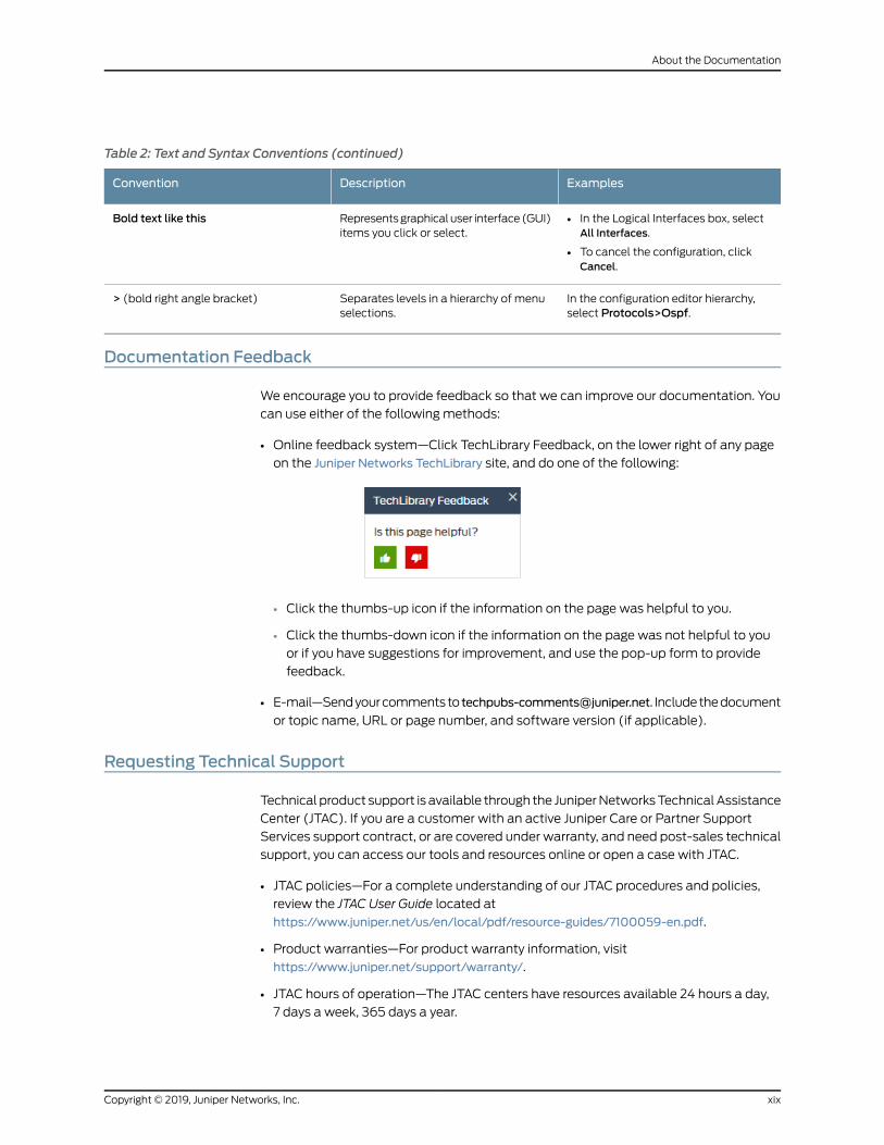
Table 2: Text and Syntax Conventions (continued)
ExamplesDescriptionConvention
• In the Logical Interfaces box, selectAll Interfaces.
• To cancel the configuration, clickCancel.
Representsgraphicaluser interface(GUI)items you click or select.
Bold text like this
In the configuration editor hierarchy,select Protocols>Ospf.
Separates levels in a hierarchy of menuselections.
> (bold right angle bracket)
Documentation Feedback
We encourage you to provide feedback so that we can improve our documentation. You
can use either of the following methods:
• Online feedback system—Click TechLibrary Feedback, on the lower right of any page
on the Juniper Networks TechLibrary site, and do one of the following:
• Click the thumbs-up icon if the information on the page was helpful to you.
• Click the thumbs-down icon if the information on the page was not helpful to you
or if you have suggestions for improvement, and use the pop-up form to provide
feedback.
• E-mail—Sendyourcommentsto [email protected]. Includethedocument
or topic name, URL or page number, and software version (if applicable).
Requesting Technical Support
Technical product support is available through the JuniperNetworksTechnicalAssistance
Center (JTAC). If you are a customer with an active Juniper Care or Partner Support
Services support contract, or are covered under warranty, and need post-sales technical
support, you can access our tools and resources online or open a case with JTAC.
• JTAC policies—For a complete understanding of our JTAC procedures and policies,
review the JTAC User Guide located at
https://www.juniper.net/us/en/local/pdf/resource-guides/7100059-en.pdf.
• Product warranties—For product warranty information, visit
https://www.juniper.net/support/warranty/.
• JTAC hours of operation—The JTAC centers have resources available 24 hours a day,
7 days a week, 365 days a year.
xixCopyright © 2019, Juniper Networks, Inc.
About the Documentation

Self-Help Online Tools and Resources
For quick and easy problem resolution, Juniper Networks has designed an online
self-service portal called the Customer Support Center (CSC) that provides youwith the
following features:
• Find CSC offerings: https://www.juniper.net/customers/support/
• Search for known bugs: https://prsearch.juniper.net/
• Find product documentation: https://www.juniper.net/documentation/
• Find solutions and answer questions using our Knowledge Base: https://kb.juniper.net/
• Download the latest versions of software and review release notes:
https://www.juniper.net/customers/csc/software/
• Search technical bulletins for relevant hardware and software notifications:
https://kb.juniper.net/InfoCenter/
• Join and participate in the Juniper Networks Community Forum:
https://www.juniper.net/company/communities/
• Create a service request online: https://myjuniper.juniper.net
Toverify serviceentitlementbyproduct serial number, useourSerialNumberEntitlement
(SNE) Tool: https://entitlementsearch.juniper.net/entitlementsearch/
Creating a Service Request with JTAC
You can create a service request with JTAC on theWeb or by telephone.
• Visit https://myjuniper.juniper.net.
• Call 1-888-314-JTAC (1-888-314-5822 toll-free in the USA, Canada, and Mexico).
For international or direct-dial options in countries without toll-free numbers, see
https://support.juniper.net/support/requesting-support/.
Copyright © 2019, Juniper Networks, Inc.xx
ATM Interfaces Feature Guide for Routing Devices

PART 1
ATM Interfaces
• ATM Interfaces Overview on page 3
• Configuring ATM Interfaces on page 27
• Configuring Passive Monitoring on ATM Interfaces on page 139
1Copyright © 2019, Juniper Networks, Inc.

Copyright © 2019, Juniper Networks, Inc.2
ATM Interfaces Feature Guide for Routing Devices

CHAPTER 1
ATM Interfaces Overview
• ATM Interfaces Overview on page 3
• ATM Pseudowire Overview on page 5
• Understanding Inverse Multiplexing for ATM on page 5
• Understanding ATM IMA Configuration on ACX Series Router on page 9
• Understanding CoS on ATM IMA Pseudowire Interfaces Overview on page 16
• Supported Features on ATM1 and ATM2 IQ Interfaces on page 18
• ATMOAM F4 and F5 Cells on ACX Series Routers on page 23
ATM Interfaces Overview
Asynchronous Transfer Mode (ATM) is a network protocol designed to facilitate the
simultaneous handling of various types of traffic streams (voice, data, and video) at very
high speeds over the same physical connection. By always using 53-byte cells, ATM
simplifies thedesignof hardware, enabling it toquicklydetermine thedestinationaddress
of each cell. This allows simple switching of network traffic at much higher speeds than
are easily accomplished using protocols with variable sizes of transfer units, such as
Frame Relay and Transmission Control Protocol/Internet Protocol (TCP/IP).
AlthoughATMwasdesigned to operatewithout the requirement of any other networking
protocol, other protocols are frequently segmented and encapsulated across multiple,
smaller ATM cells. This makes ATM a transport mechanism for preexisting technologies
such as Frame Relay and the TCP/IP family of protocols.
ATM relies on the concepts of virtual paths and virtual circuits. A virtual path, represented
by a specific virtual path identifier (VPI), establishes a route between two devices in a
network. Each VPI can contain multiple virtual circuits, each represented by a virtual
circuit identifier (VCI).
VPIs and VCIs are local to the router, which means that only the two devices connected
by the VCI or VPI need know the details of the connection. In a typical ATM network, user
datamight traversemultiple connections, usingmany different VPI andVCI connections.
Each end device, just like each device in the network, needs to know only the VCI and VPI
information for the path to the next device.
3Copyright © 2019, Juniper Networks, Inc.

NOTE: TheATMthree-bit payload type identifier (PTI) field is not supported.
WithATM2 intelligentqueuing (IQ) interfaces, youcanconfigure virtual path (VP) shaping
and Operation, Administration, and Management (OAM) F4 cell flows.
RelatedDocumentation
Supported Features on ATM1 and ATM2 IQ Interfaces on page 18•
• Configuring Communication with Directly Attached ATM Switches and Routers on
page 47
• Enabling ILMI for Cell Relay on page 48
• Configuring Communication with Directly Attached ATM Switches and Routers on
page 47
• Enabling ILMI for Cell Relay on page 48
• Enabling Passive Monitoring on ATM Interfaces on page 139
• Removing MPLS Labels from Incoming Packets on page 140
• Configuring the ATM PIC Type on page 39
• Configuring ATM Cell-Relay Promiscuous Mode on page 42
• Configuring ATM Cell-Relay Pseudowire on page 71
• Configuring the MaximumNumber of ATM1 VCs on a VP on page 46
• Configuring Layer 2 Circuit Transport Mode on page 54
• Configuring Layer 2 Circuit Trunk Mode Scheduling Overview on page 76
• Configuring CoS Queues in Layer 2 Circuit Trunk Mode on page 77
• Configuring the Layer 2 Circuit Cell-Relay Cell MaximumOverview on page 74
• Configuring the OAM F4 Cell Flows on page 86
• Defining Virtual Path Tunnels on page 113
• Configuring a Point-to-Point ATM1 or ATM2 IQ Connection on page 115
• Configuring a Point-to-Multipoint ATM1 or ATM2 IQ Connection on page 116
• Configuring a Multicast-Capable ATM1 or ATM2 IQ Connection on page 86
• Configuring Inverse ATM1 or ATM2 ARP on page 117
• Defining the ATM Traffic-Shaping Profile Overview on page 107
• Configuring the ATM1 Queue Length on page 114
• Configuring the ATM2 IQ EPD Threshold on page 131
• Configuring Two EPD Thresholds per Queue on page 133
• Configuring the ATM2 IQ TransmissionWeight on page 133
• Defining the ATMOAM F5 Loopback Cell Period on page 88
Copyright © 2019, Juniper Networks, Inc.4
ATM Interfaces Feature Guide for Routing Devices

• Configuring the ATMOAM F5 Loopback Cell Threshold on page 86
• Configuring ATM Interface Encapsulation on page 51
• Configuring an ATM1 Cell-Relay Circuit Overview on page 80
• Configuring PPP over ATM2 Encapsulation Overview on page 82
• Configuring E3 and T3 Parameters on ATM Interfaces on page 49
• Configuring SONET/SDH Parameters on ATM Interfaces on page 50
• ATM2 IQ VC Tunnel CoS Components Overview on page 117
• Example: Configuring ATM1 Interfaces on page 36
• Example: Configuring ATM2 IQ Interfaces on page 38
ATMPseudowire Overview
An Asynchronous Transfer Mode (ATM) pseudowire acts as a Layer 2 circuit or service,
whichallows themigrationofATMservices toanMPLSpacket-switchednetworkwithout
having toprovision theATMsubscriber or customeredge (CE)device.Whenyouconfigure
an ATM pseudowire, the network between the customer edge (CE) routers appears
transparent to the CE routers, making it seem that the CE routers are directly connected
across a time-division multiplex (TDM) leased line. ATM pseudowires are primarily used
in an ATM service provider’s network to connect existing ATM switches across a higher
speed packet-switched network or to provide ATM backhaul services for remote access
to existing ATM networks.
On ACX series routers, you configure an ATM pseudowire with Layer 2 encapsulation for
Inverse Multiplexing for ATM (IMA).
RelatedDocumentation
Understanding Encapsulation on an Interface•
• Configuring Inverse Multiplexing for ATM (IMA) on ACX Series on page 28
• Pseudowire Overview for ACX Series Universal Metro Routers
• TDM Pseudowires Overview
• Ethernet Pseudowire Overview
Understanding InverseMultiplexing for ATM
Inverse multiplexing for ATM (IMA) is a technique of transporting ATM traffic over a
bundle of T1 or E1 interfaces. The following sections explain IMA in detail:
• Understanding Asynchronous Transfer Mode on page 6
• Understanding Inverse Multiplexing for ATM on page 6
• How Inverse Multiplexing for ATMWorks on page 6
• Supported Platforms on page 8
5Copyright © 2019, Juniper Networks, Inc.
Chapter 1: ATM Interfaces Overview
Understanding Asynchronous Transfer Mode
AsynchronousTransferMode (ATM) is a high-speednetworking technology that handles
data in fixed-size units called cells. It enables high-speed communication between edge
routers and core routers in an ATM network.
ATM isdesigned to facilitate thesimultaneoushandlingof various typesof traffic streams
(voice, data, and video) at very high speeds over a dedicated connection. ATM uses
asynchronous time-division multiplexing (TDM) and it encodes data into 53-byte cells,
thereby simplifying the design of hardware and enabling it to quickly determine the
destinationaddressofeachcell. ATMoperatesovereither fiberoptic cablesor twisted-pair
cables. Each ATM PIC is assigned an ATM switch ID that displays the switch’s IP address
and the local interface names of the adjacent Fore ATM switches. For information about
ATM PICs, see the platform-specific Hardware Guide.
ATM relies on the concepts of virtual paths (VPs)andvirtual circuits (VCs). A virtual path,
represented by a specific virtual path identifier (VPI), establishes a route between two
devices in a network. Each VPI can contain multiple VCs, each represented by a virtual
circuit identifier (VCI). VPIs and VCIs are local to the router, which means that only the
two devices connected by the VCI or VPI need know the details of the connection. In a
typicalATMnetwork, userdatamight traversemultiple connections, usingmanydifferent
VPI and VCI connections. Each end device, just like each device in the network, needs to
know only the VCI and VPI information for the path to the next device.
An ATM interface is indicated by the at-fpc/pic/port CLI descriptor.
Understanding InverseMultiplexing for ATM
Inverse multiplexing is a method where a single data stream is divided into multiple
smaller data streams that are transmitted over either fiber optic cables or twisted pair
cablesandare recombinedon theother end to formtheoriginal datastream.This concept
is useful for attaininghigh-speeddata transmission rates.This concepthasbeenextended
to ATM and is called inverse multiplexing for ATM or IMA.
IMA is a technique of transporting ATM traffic over a bundle of T1 or E1 interfaces. IMA
divides a single data stream into multiple smaller data streams, that is transmitted at
the same time across separate channels (such as T1 or E1 interfaces) and then
reconstructed at the other end back into the original data stream.
Two versions of IMA are available–IMA 1.0 (af-phy-0086.000-IMA) and IMA 1.1
(af-phy-0086.001-IMA). You can configure either of these versions, by using the Junos
OS CLI. If not specified, IMA 1.1 is selected by default. Note that IMA 1.0 and IMA 1.1 do not
interoperate.The IMAv1.1 specification increments theOAM(operationsandmaintenance)
label value used in the IMA OAM cells in order to differentiate v1.1 from v1.0 IMA units.
How InverseMultiplexing for ATMWorks
Figure 1 on page 7 displays IMA frames on different links. An IMA frame consists of ATM
cells, an ICP cell, and filler cells (if required).
Copyright © 2019, Juniper Networks, Inc.6
ATM Interfaces Feature Guide for Routing Devices

Figure 1: IMA Frames on Links
On the transmission side of the ATM IMA network, the ATM cell stream (received from
the ATM layer) is divided across multiple links in an IMA group on a cell by cell basis. On
the receiving end of the ATM IMA network, the cells are recombined to form the original
ATM cells stream (with the help of ICP cells), and then passed on to the ATM layer.
Figure 2 on page 7 displays an IMA frame being transmitted and received through an
IMA group.
Figure 2: IMA Frames Transmitted Through IMA Group
IMAControl Protocol (ICP) cells are special cells that are sent over theATM IMA interface
with the ATM cell stream to help align the ATM cells at the receiving end. An ICP cell
tracks link differential delay, reduces cell delay variation (CDV), and performs other
functions.
When there are noATMcells to be sent on an IMA frame, the IMA transmitter inserts filler
cells to maintain a continuous stream of cells at the physical layer. The filler cells are
discarded by the IMA receiver. An OAM cell has codes that define it as an ICP cell or a
filler cell.
7Copyright © 2019, Juniper Networks, Inc.
Chapter 1: ATM Interfaces Overview
Supported Platforms
The followingare thevarious JuniperNetworks routersand their components that support
inverse multiplexing for ATM (IMA):
• 16-portChannelizedE1/T1Circuit EmulationMIC (MIC-3D-16CHE1-T1-CE)onMXSeries
routers (from Junos OS Release 13.2R1 onward).
• 4-port Channelized OC3/STM1 (Multi-Rate) Circuit Emulation MIC with SFP
(MIC-3D-4COC3-1COC12-CE) on MX Series routers (from Junos OS Release 13.2R1
onward).
• 4-port ChannelizedOC3/STM1Circuit EmulationPICwithSFP (PB-4CHOC3-CE-SFP)
on M7i, M10i, M40e, M120, and M320 routers supports channelized OC3/STM1 (down
to T1) ATM IMA.
• 12-port E1/T1 Circuit Emulation PIC (PB-12T1E1-CE-TELCO) on M7i, M10i, M40e, M120,
and M320 routers supports discrete T1 ATM IMA.
NOTE: Circuit Emulation PICs require firmware version rom-ce-9.3.pbin or
rom-ce-10.0.pbin for ATM IMA functionality on M7i, M10i, M40e, M120, and
M320 routers running Junos OS Release 10.0R1 or later.
RelatedDocumentation
ATM IMA Configuration Overview•
• ATM Support on Circuit Emulation PICs Overview
• Configuring ATM IMA
Copyright © 2019, Juniper Networks, Inc.8
ATM Interfaces Feature Guide for Routing Devices

Understanding ATM IMA Configuration on ACX Series Router
IMA involves inverse multiplexing and demultiplexing of ATM cells in a round-robin
sequence among links grouped to form a higher-bandwidth logical link whose rate is the
sum of all the link rates. This group of links is called an IMA group. An IMA group can also
be defined as a group of links at the transmitting end that is used to establish an IMA
virtual link to the receiving end. The IMA virtual link is a virtual link that is established
between two IMA units or routers over a number of physical links (in an IMA group). IMA
groups terminate at each end of the IMA virtual link.
You can configure 42 IMA groups. Each group can contain from 1 through 32 links.
You can configure amaximum of 16 IMA groups on the 16-port Channelized E1/T1 Circuit
EmulationMIC (ACX-MIC-16CHE1-T1-CE) and each group can have from 1 through 8 IMA
links. Port numbers starting from 0 through 15 are used for T1/E1 ports; therefore, IMA
port numbers start from 16 onward.
You can configure a maximum of 16 IMA groups on the Channelized OC3/STM1
(Multi-Rate) Circuit Emulation MIC with SFP (ACX-MIC-4COC3-1COC12CE).
To configure an IMA group, execute the set chassis fpc fpc-slot pic pic-slot aggregated
devices ima device-count count configuration command, where count results in the
creation of interfaces from at-x/y/g through at-x/y/g+count-1. The variable g is picked
from 16onward. For example, if the count variable is set to4, then thenewATM interfaces
are created from at-x/y/16 through at-x/y/19.
You can implement inverse multiplexing for ATM (IMA) on Juniper Networks ACX Series
routers by configuring an IMA group and its options. The following sections explain the
various options that can be set for an IMA group:
• IMA Version on page 10
• IMA Frame Length on page 10
• Transmit Clock on page 10
• IMA Group Symmetry on page 10
• Minimum Active Links on page 11
• State Transition Variables: Alpha, Beta, and Gamma on page 11
• IMA Link Addition and Deletion on page 11
• IMA Test Pattern Procedure on page 12
• IMA Group Alarms and Group Defects on page 12
• IMA Link Alarms and Link Defects on page 13
• IMA Group Statistics on page 14
• IMA Link Statistics on page 15
• IMA Clocking on page 16
• Differential Delay on page 16
9Copyright © 2019, Juniper Networks, Inc.
Chapter 1: ATM Interfaces Overview

IMA Version
Either IMA 1.0 (af-phy-0086.000-IMA)or IMA 1.1 (af-phy-0086.001-IMA)canbeselected
through the CLI. To choose the IMA specification version, execute the set interfaces
interface-name ima-group-options (1.0|1.1) configuration command. Note that, if you do
not specify the version, IMA 1.1 is selected by default.
NOTE: IMA 1.0 and IMA 1.1 do not interoperate.
The IMAv1.1 specification increments theoperationsandmaintenance (OAM) label value
used in the IMA OAM cells in order to differentiate v1.1 from v1.0 IMA units.
IMA Frame Length
An IMA frame consists of ATM cells, an ICP cell, and filler cells (if required). When you
configure an IMA group, you can choose a frame length of 32, 64, 128, or 256. The frame
length can be selected independently in each direction and in each group. To set the
frame length, execute the set interface interface-name frame-length (32 |64 |128 |256)
configuration command. Note that if the frame length is not specified, the frame length
value of 128 is selected by default.
Transmit Clock
When you create an IMAgroup, you can configure a common transmit clock timingmode
or an independent transmit clock timing mode to reflect the primary reference source
(PRS) of the clock for each link in a group. By default, the commonmode is selected. To
select the transmit clock timing mode, execute the set interface interface-name
ima-group-options transmit-clock (common | independent) configuration command.
IMA Group Symmetry
You can configure an IMA group to allow symmetric or asymmetric cell rate transfer over
an IMA virtual link. You can configure the IMA group with one of the following modes:
• Symmetrical configuration and operation—In this mode, on the ATM IMA device, an
IMA link must be configured in each direction for all physical links that the ATM IMA
device is configured to use. In this mode, the ATM IMA device can transmit and receive
ATM layer cells over the physical links onwhich the IMA links running in both directions
are Active.
• Symmetrical configuration and asymmetrical operation—In this mode, on the ATM
IMA device, an IMA link must be configured in each direction for all physical links that
theATM IMAdevice is configured to use. In thismode, theATM IMAdevice can transmit
ATM layer cells over the physical links on which the IMA links in the transmit direction
are Active, while the IMA links in the receive direction are not Active or contrariwise.
Asymmetrical configuration and operation are not supported.
Themode can be configured through the CLI when an IMA group is created. To select
thesymmetryoption, execute theset interface interface-name ima-group-optionssymmetry
Copyright © 2019, Juniper Networks, Inc.10
ATM Interfaces Feature Guide for Routing Devices

(symmetrical-config-and-operation | symmetrical-config-asymmetrical-operation)
configurationcommand.Bydefault, symmetrical configurationandoperation is selected.
MinimumActive Links
You can set the minimum active links for an IMA group from 1 through 32.
• PTxis the minimum number of links required to be active in the transmit direction for
the IMA group to move into the operational state.
• PRxis theminimumnumber of links required to be active in the receive direction for the
IMA group to move into the operational state.
You configure PTxand P
Rxthrough the CLI when an IMA group is created. By default, 1 is
selected.
For a symmetrical configuration, PTxis equal to P
Rx.
To set minimum links, execute the set interface interface-name ima-group-options
minimum-links links configuration command. By default, symmetrical configuration and
operation is selected.
State Transition Variables: Alpha, Beta, and Gamma
Frame synchronization is a process of recovery of the aggregated frames. The frame
synchronization states form a basis for the different error andmaintenance states. You
canconfigure the IMA framesynchronization link state transition variables asalpha, beta,
and gamma. The valid ranges and default values are shown in Table 3 on page 11.
Table 3: IMA Frame Synchronization Link State Transition Variables
DescriptionDefaultRangeSetting
Consecutive invalid ICP cells21–2alpha
Consecutive errored ICP cells21–5beta
Consecutive valid ICP cells11–5gamma
To set the frame synchronization option, execute the set interface interface-name
ima-group-options frame-synchronization alpha number beta number gamma number
configuration command.
IMA Link Addition and Deletion
When an IMA group is up, you can add links to or delete links from the group without
dropping cells.
To create an IMA link, youmust:
• Configure theencapsulationas imaat the [edit interfaces interface-nameencapsulation]
hierarchy level.
11Copyright © 2019, Juniper Networks, Inc.
Chapter 1: ATM Interfaces Overview
• Configure an ATM interface with one T1 link or one E1 link with the set interfaces
interface-name ima-link-options group-id g configuration command.
The interface-name variable refers to the T1 or E1 interface to be set as an IMA interface
link and the variable g refers to the port in the at-x/y/g interface.
To delete the configured IMA link, youmust execute the following configuration
commands:
• delete interfaces interface-name encapsulation ima
• delete interfaces interface-name ima-link-options group g
IMA Test Pattern Procedure
A test pattern procedure is supported for IMA to test the ATM, T1, and E1 interfaces for
irregularities. You can use the CLI to start and end the test pattern procedure.
The following options can be set according to the requirement at the [edit interface
interface-name ima-group-options test-procedure] hierarchy level:
• interface interface-name—Interface name of the IMA link to test.
• pattern number—IMA test pattern that can be set from 1 through 254
• period number—Length of the IMA test pattern that can be set from 1 second through
4,294,967,294 seconds. Default is 10 seconds.
To perform the test pattern procedure, execute the test interface interface-name
ima-test-start and test interface interface-name ima-test-stop operational mode
commands to start and to stop the IMA test, respectively.
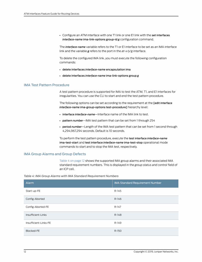
IMA Group Alarms and Group Defects
Table 4 on page 12 shows the supported IMA group alarms and their associated IMA
standard requirement numbers. This is displayed in the group status and control field of
an ICP cell.
Table 4: IMA Group Alarmswith IMA Standard Requirement Numbers
IMA Standard Requirement NumberAlarm
R-145Start-up-FE
R-146Config-Aborted
R-147Config-Aborted-FE
R-148Insufficient-Links
R-149Insufficient-Links-FE
R-150Blocked-FE
Copyright © 2019, Juniper Networks, Inc.12
ATM Interfaces Feature Guide for Routing Devices

Table 4: IMA Group Alarmswith IMA Standard Requirement Numbers (continued)
IMA Standard Requirement NumberAlarm
R-151Timing-Mismatch
Blocked
Version-Mismatch
Table 5 on page 13 shows the supported IMA group defects and their associated IMA
standard requirement numbers. This is displayed in the group status and control field of
an ICP cell.
Table 5: IMA Group Defects with IMA Standard Requirement Numbers
IMA Standard Requirement NumberDefects
R-145Start-up-FE
R-146Config-Aborted
R-147Config-Aborted-FE
R-148Insufficient-Links
R-149Insufficient-Links-FE
R-150Blocked-FE
R-151Timing-Mismatch
Blocked
Version-Mismatch
IMA Link Alarms and Link Defects
Table 6 on page 13 shows the supported IMA link alarms that are reported to the IMA
unit management with their associated IMA standard requirement numbers.
Table 6: IMA Link Alarmswith IMA Standard Requirement Numbers
DescriptionIMA Standard RequirementNumberAlarm
Loss of IMA frameR-138LIF
Link out of delay synchronizationR-139LODS
Remote defect/failureR-140RFI-IMA
13Copyright © 2019, Juniper Networks, Inc.
Chapter 1: ATM Interfaces Overview

Table 6: IMA Link Alarmswith IMA Standard Requirement Numbers (continued)
DescriptionIMA Standard RequirementNumberAlarm
Transmit misconnectedR-141Tx-Mis-Connected
Receive misconnectedR-142Rx-Mis-Connected
Transmit unusable far endR-143Tx-Unusable-FE
Receive unusable far endR-144Rx-Unusable-FE
Link faultLink Fault
An IMA unit management is defined by SNMPMIBs.
Table 7 on page 14 shows the supported IMA link defects that are reported to the unit
management with their associated IMA standard requirement numbers.
Table 7: IMA Link Defects with IMA Standard Requirement Numbers
DescriptionIMA Standard RequirementNumberDefect
Loss of IMA frameR-138LIF
Link out of delay synchronizationR-139LODS
Remote defect/failureR-140RFI-IMA
Transmit misconnectedR-141Tx-Mis-Connected
Receive misconnectedR-142Rx-Mis-Connected
Transmit unusable far endR-143Tx-Unusable-FE
Receive unusable far endR-144Rx-Unusable-FE
Link faultLink Fault
IMA Group Statistics
You can use the show interfaces command to display the following IMA group statistics:
• Near-end failure count
• Far-end failure count
• Receive end (Rx) faulty cells due to address mismatch
Copyright © 2019, Juniper Networks, Inc.14
ATM Interfaces Feature Guide for Routing Devices

• Running seconds
• Unavailable seconds
For more information about IMA group statistics, see the show interfaces command
description in the CLI Explorer.
IMA Link Statistics
Table 8 on page 15 shows the IMA link statistics.
Table 8: IMA Link Statistics with IMA Standard Requirement Numbers
IMA Standard Requirement NumberPerformance Parameter
–Rx LIF
–Rx ICP cells
R-106Rx errored ICP cells
R-106Rx LODS
R-107Rx ICP violation
O-17Rx stuff
R-108Near-end Rx SES
R-110Near-end Rx UAS
R-113Near-end Rx UUS
R-117Near-end Rx failure
–Near-end Tx failure
R-109Far-end Rx SES
R-111Far-end Rx UAS
R-115Far-end Rx UUS
–Far-end defects
–Far-end Rx failure
–Tx ICP cells
O-16Tx stuff
R-112Near-end Tx UUS
15Copyright © 2019, Juniper Networks, Inc.
Chapter 1: ATM Interfaces Overview
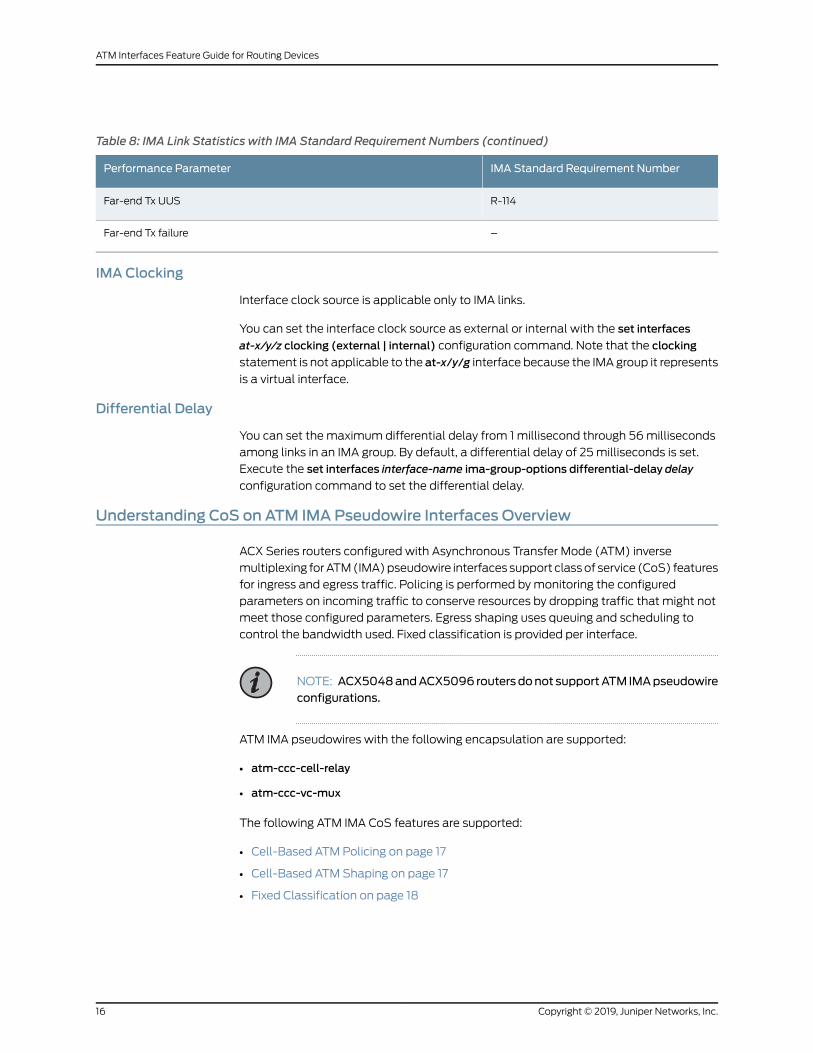
Table 8: IMA Link Statistics with IMA Standard Requirement Numbers (continued)
IMA Standard Requirement NumberPerformance Parameter
R-114Far-end Tx UUS
–Far-end Tx failure
IMA Clocking
Interface clock source is applicable only to IMA links.
You can set the interface clock source as external or internal with the set interfaces
at-x/y/z clocking (external | internal) configuration command. Note that the clocking
statement is not applicable to the at-x/y/g interface because the IMAgroup it represents
is a virtual interface.
Differential Delay
You can set the maximum differential delay from 1 millisecond through 56milliseconds
among links in an IMA group. By default, a differential delay of 25milliseconds is set.
Execute the set interfaces interface-name ima-group-options differential-delay delay
configuration command to set the differential delay.
Understanding CoS on ATM IMA Pseudowire Interfaces Overview
ACX Series routers configured with Asynchronous Transfer Mode (ATM) inverse
multiplexing forATM(IMA)pseudowire interfaces support classof service (CoS) features
for ingress and egress traffic. Policing is performed bymonitoring the configured
parameters on incoming traffic to conserve resources by dropping traffic that might not
meet those configured parameters. Egress shaping uses queuing and scheduling to
control the bandwidth used. Fixed classification is provided per interface.
NOTE: ACX5048andACX5096 routersdonot supportATM IMApseudowireconfigurations.
ATM IMA pseudowires with the following encapsulation are supported:
• atm-ccc-cell-relay
• atm-ccc-vc-mux
The following ATM IMA CoS features are supported:
• Cell-Based ATM Policing on page 17
• Cell-Based ATM Shaping on page 17
• Fixed Classification on page 18
Copyright © 2019, Juniper Networks, Inc.16
ATM Interfaces Feature Guide for Routing Devices
Cell-Based ATMPolicing
Policing, or rate limiting, enables you to limit the amount of traffic that passes into or out
of the interface. Policing works with firewall filters to thwart denial-of-service (DoS)
attacks. Networks police traffic by limiting the input or output transmission rate of a class
of traffic on the basis of user-defined criteria. The ATM policer controls the maximum
rate of traffic sent from or received on the interface onwhich it is applied. To apply limits
to the traffic flow, configure the cdvt and peak-rate parameterswithin the policer. Define
the policing-action parameter as discard, discard-tag, or count to set a consequence for
the packets that exceed these limits. The consequence of configuring the discard-tag
statement is usually a higher loss priority so that if those packets encounter downstream
congestion, they are discarded first.
On ACX Series routers, policing is cell based and configured in the ingress path of the
ATM IMA pseudowire interface at the [edit firewall] hierarchy level. The following ATM
policing features are supported:
• ATMAdaption Layer 5 (AAL5) pseudowires onwhich cell-based policing is performed
before packet assembly.
• Per-ATM IMA channel policing.
• Traffic classes—Constantbit rate (cbr), real-timevariablebit rate (rtvbr), non-real-time
variable bit rate (nrtvbr), and unspecified bit rate (ubr). All traffic classesmust include
the peak-rate and cdvt statements for the configuration to work. With the peak-rate
statement, youcan limit themaximumtraffic allowedby specifying the largest number
of cells per second that the policer processes before it drops packets. The cdvt
statement ensures that the configuration functions correctly.
• For nonconforming cells, thediscard,discard-tag, and countactionsat the [edit firewall
atm-policerpolicer-name]hierarchy level. Thediscard-tagaction isapplicable tovariable
bit-rate—nrtvbr and rtvbr—traffic classes.
Cell-Based ATMShaping
Cell-based ATM shaping uses cell-based queuing and scheduling to determine the
maximum amount of traffic that can be transmitted on an ATM IMA pseudowire.
Packet-basedshaping is not supported.OnACXSeries routers, ATMshaping is configured
in the egress path of the ATM IMA pseudowire interface at the [edit class-of-service]
hierarchy level. The following ATM shaping features are supported:
• Prioritized bit rate—Constant bit rate (cbr) is the highest priority, followed by variable
bit rate—nrtvbr and rtvbr. Unspecified bit rate (ubr) is similar to the best-effort service
for Ethernet traffic.
• Constant bit rate shaping—Constant bit rate (cbr) shaping uses the peak cell rate to
limit the number of cells per second that the shaper processes before it drops packets.
17Copyright © 2019, Juniper Networks, Inc.
Chapter 1: ATM Interfaces Overview

• Variable bit rate shaping—Variable bit rate shaping (nrtvbr and rtvbr) uses peak-rate
and sustained-rate.
• Unspecifiedbit rate—Unspecifiedbit rate (ubr) usespeak-ratewith the lowest transmit
priority.
The default shaping parameter is unspecified bit rate, which is similar to the best-effort
service for Ethernet traffic.
Fixed Classification
Fixed classifiers map all traffic on an interface to the forwarding class and loss priority.
The forwarding class determines the output queue. A scheduler uses the loss priority to
control packet discard during periods of congestion by associating different drop profiles
with different loss priorities. On ACX Series routers, the fixed classifier is associated with
the ingress interface. Packets are assigned on the basis of the type of fixed classification
associated with the logical interface. To configure a fixed classifier, include the
forwarding-class class-name statement at the [edit class-of-service interface
interface-name unit logical-unit-number hierarchy level.
RelatedDocumentation
Configuring Fixed Classification on an ATM IMA Pseudowire on page 89•
• Configuring Policing on an ATM IMA Pseudowire on page 99
• Configuring Shaping on an ATM IMA Pseudowire on page 93
Supported Features on ATM1 and ATM2 IQ Interfaces
Table 9 on page 18 lists the supported features on ATM1 and ATM2 IQ interfaces.
Table 9: ATM1 and ATM2 IQ Supported Features
CommentsATM2 IQATM1Item
Encapsulation and Transport Modes
For ATM1 and ATM2 IQ Physical Interface Cards (PICs), youcanconfigureanycombinationofAAL5CCC,nonpromiscuouscell relay, and AAL5 permanent virtual connections (PVCs)on the same PIC at the same time.
See “Configuring ATM Interface Encapsulation” on page 51.
SupportedSupportedATM Adaptation Layer 5 (AAL5)circuit cross-connect (CCC)
Cell-relay accumulation mode is per PIC, not per port. If youconfigure accumulation mode, the entire ATM1 PIC uses theconfiguredmode.
See “Configuring ATM Interface Encapsulation” on page 51.
Notsupported
SupportedCell-relay accumulation mode: Theincoming cells (1 to 8) are packagedinto a single packet and forwarded tothe label-switched path (LSP).
Copyright © 2019, Juniper Networks, Inc.18
ATM Interfaces Feature Guide for Routing Devices
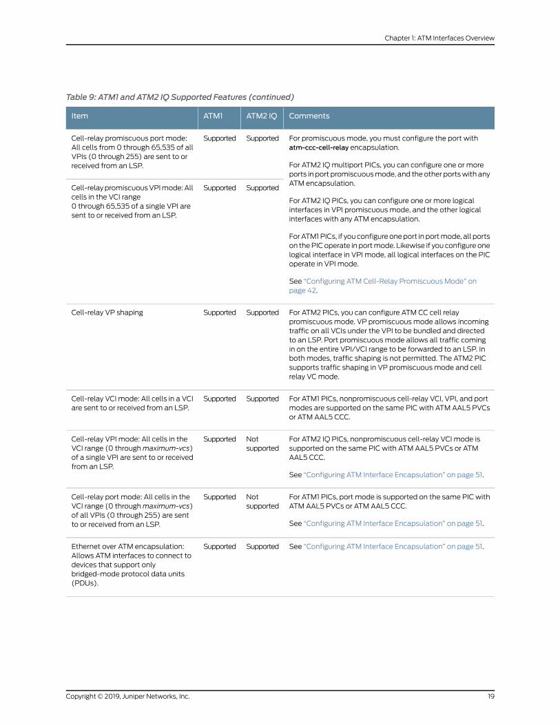
Table 9: ATM1 and ATM2 IQ Supported Features (continued)
CommentsATM2 IQATM1Item
For promiscuous mode, youmust configure the port withatm-ccc-cell-relay encapsulation.
For ATM2 IQmultiport PICs, you can configure one or moreports in port promiscuousmode, and the other portswith anyATM encapsulation.
For ATM2 IQ PICs, you can configure one or more logicalinterfaces in VPI promiscuous mode, and the other logicalinterfaces with any ATM encapsulation.
ForATM1PICs, if you configureoneport in portmode, all portson thePICoperate in portmode. Likewise if you configure onelogical interface in VPI mode, all logical interfaces on the PICoperate in VPI mode.
See “Configuring ATM Cell-Relay Promiscuous Mode” onpage 42.
SupportedSupportedCell-relay promiscuous port mode:All cells from 0 through 65,535 of allVPIs (0 through 255) are sent to orreceived from an LSP.
SupportedSupportedCell-relaypromiscuousVPImode:Allcells in the VCI range0 through 65,535 of a single VPI aresent to or received from an LSP.
For ATM2 PICs, you can configure ATM CC cell relaypromiscuous mode. VP promiscuous mode allows incomingtraffic on all VCIs under the VPI to be bundled and directedto an LSP. Port promiscuous mode allows all traffic comingin on the entire VPI/VCI range to be forwarded to an LSP. Inboth modes, traffic shaping is not permitted. The ATM2 PICsupports traffic shaping in VP promiscuous mode and cellrelay VCmode.
SupportedSupportedCell-relay VP shaping
For ATM1 PICs, nonpromiscuous cell-relay VCI, VPI, and portmodes are supported on the same PIC with ATM AAL5 PVCsor ATM AAL5 CCC.
SupportedSupportedCell-relay VCI mode: All cells in a VCIare sent to or received from an LSP.
For ATM2 IQ PICs, nonpromiscuous cell-relay VCI mode issupported on the same PIC with ATM AAL5 PVCs or ATMAAL5 CCC.
See “Configuring ATM Interface Encapsulation” on page 51.
Notsupported
SupportedCell-relay VPI mode: All cells in theVCI range (0 throughmaximum-vcs)of a single VPI are sent to or receivedfrom an LSP.
For ATM1 PICs, port mode is supported on the same PIC withATM AAL5 PVCs or ATM AAL5 CCC.
See “Configuring ATM Interface Encapsulation” on page 51.
Notsupported
SupportedCell-relay port mode: All cells in theVCI range (0 throughmaximum-vcs)of all VPIs (0 through 255) are sentto or received from an LSP.
See “Configuring ATM Interface Encapsulation” on page 51.SupportedSupportedEthernet over ATM encapsulation:Allows ATM interfaces to connect todevices that support onlybridged-mode protocol data units(PDUs).
19Copyright © 2019, Juniper Networks, Inc.
Chapter 1: ATM Interfaces Overview
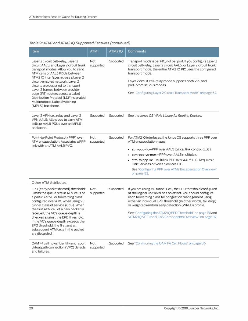
Table 9: ATM1 and ATM2 IQ Supported Features (continued)
CommentsATM2 IQATM1Item
Transportmode isperPIC, notperport. If youconfigureLayer 2circuit cell-relay, Layer 2 circuit AAL5, or Layer 2 circuit trunktransport mode, the entire ATM2 IQ PIC uses the configuredtransport mode.
Layer 2 circuit cell-relay mode supports both VP- andport-promiscuous modes.
See “Configuring Layer 2 Circuit Transport Mode” on page 54.
SupportedNotsupported
Layer 2 circuit cell-relay, Layer 2circuit AAL5, and Layer 2 circuit trunktransport modes: Allow you to sendATM cells or AAL5 PDUs betweenATM2 IQ interfaces across a Layer 2circuit-enabled network. Layer 2circuits are designed to transportLayer 2 frames between provideredge (PE) routers across a LabelDistribution Protocol (LDP)-signaledMultiprotocol Label Switching(MPLS) backbone.
See the Junos OS VPNs Library for Routing Devices.SupportedSupportedLayer 2 VPN cell relay and Layer 2VPN AAL5: Allow you to carry ATMcells or AAL5 PDUs over an MPLSbackbone.
ForATM2 IQ interfaces, the JunosOSsupports threePPPoverATM encapsulation types:
• atm-ppp-llc—PPP over AAL5 logical link control (LLC).
• atm-ppp-vc-mux—PPP over AAL5multiplex.
• atm-mlppp-llc—Multilink PPP over AAL5 LLC. Requires aLink Services or Voice Services PIC.
See “Configuring PPP over ATM2 EncapsulationOverview”on page 82.
SupportedNotsupported
Point-to-Point Protocol (PPP) overATMencapsulation:AssociatesaPPPlink with an ATM AAL5 PVC.
Other ATMAttributes
If you are using VC tunnel CoS, the EPD threshold configuredat the logical unit level has no effect. You should configureeach forwarding class for congestion management usingeither an individual EPD threshold (in other words, tail drop)or weighted random early detection (WRED) profile.
See “Configuring theATM2 IQEPDThreshold”onpage 131and“ATM2 IQVCTunnel CoSComponentsOverview” on page 117.
SupportedNotsupported
EPD(early packetdiscard) threshold:Limits the queue size in ATM cells ofa particular VC or forwarding classconfigured over a VC when using VCtunnel class of service (CoS). Whenthe first ATM cell of a new packet isreceived, the VC’s queue depth ischecked against the EPD threshold.If the VC’s queue depth exceeds theEPD threshold, the first and allsubsequent ATM cells in the packetare discarded.
See “Configuring the OAM F4 Cell Flows” on page 86.SupportedNotsupported
OAMF4cell flows: Identify and reportvirtualpathconnection(VPC)defectsand failures.
Copyright © 2019, Juniper Networks, Inc.20
ATM Interfaces Feature Guide for Routing Devices

Table 9: ATM1 and ATM2 IQ Supported Features (continued)
CommentsATM2 IQATM1Item
For ATM1 interfaces, when an OAM F5 loopback request isreceived, the response cell is sent by the PIC. The request andresponse cells are not counted in the VC, logical interface, orphysical interface statistics.
For ATM2 IQ interfaces, when an OAM F5 loopback requestis received, the response is sent by the Routing Engine. TheOAM, VC, logical interface, and physical interface statisticsare incremented.
See “Defining the ATMOAM F5 Loopback Cell Period” onpage 88 and “Configuring the ATMOAM F5 Loopback CellThreshold” on page 86.
SupportedSupportedOAM F5 loopback cell responses
See “Enabling Passive Monitoring on ATM Interfaces” onpage 139.
SupportedSupportedPassive monitoring mode
For ATM1 interfaces, you can include the pic-type atm1statement.
For ATM2 IQ interfaces, you can include the pic-type atm2statement.
See “Configuring the ATM PIC Type” on page 39.
SupportedSupportedPIC type
For ATM1 and ATM2 IQ interfaces, when you issue the ATMping command, youmust include a logical unit number in theinterface name, as shown in the following example:
ping atm interface at-1/0/0.5 vci 0.123 count 3
The logical unit number is 5 on physical interface at-1/0/0.
See the CLI Explorer.
SupportedSupportedPing
See “Configuring the ATM1 Queue Length” on page 114.Notsupported
SupportedQueue length: Limits the queue sizein packets of a particular VC.
Compared to non-real-time VBR, real-time VBR data isserviced at a higher priority. Real-time VBR is suitable forcarrying packetized video and audio.
See “Configuring ATM CBR” on page 108.
SupportedNotsupported
Real-time variable bit rate (VBR):Supports VBR data traffic withaverage and peak traffic parameters.
21Copyright © 2019, Juniper Networks, Inc.
Chapter 1: ATM Interfaces Overview
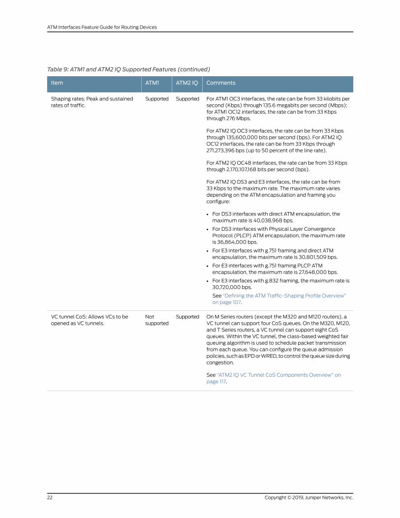
Table 9: ATM1 and ATM2 IQ Supported Features (continued)
CommentsATM2 IQATM1Item
For ATM1 OC3 interfaces, the rate can be from 33 kilobits persecond (Kbps) through 135.6 megabits per second (Mbps);for ATM1 OC12 interfaces, the rate can be from 33 Kbpsthrough 276 Mbps.
For ATM2 IQ OC3 interfaces, the rate can be from 33 Kbpsthrough 135,600,000 bits per second (bps). For ATM2 IQOC12 interfaces, the rate can be from 33 Kbps through271,273,396 bps (up to 50 percent of the line rate).
For ATM2 IQ OC48 interfaces, the rate can be from 33 Kbpsthrough 2,170,107,168 bits per second (bps).
For ATM2 IQ DS3 and E3 interfaces, the rate can be from33 Kbps to the maximum rate. Themaximum rate variesdepending on the ATM encapsulation and framing youconfigure:
• For DS3 interfaces with direct ATM encapsulation, themaximum rate is 40,038,968 bps.
• For DS3 interfaces with Physical Layer ConvergenceProtocol (PLCP) ATM encapsulation, the maximum rateis 36,864,000 bps.
• For E3 interfaces with g.751 framing and direct ATMencapsulation, the maximum rate is 30,801,509 bps.
• For E3 interfaces with g.751 framing PLCP ATMencapsulation, the maximum rate is 27,648,000 bps.
• For E3 interfaces with g.832 framing, the maximum rate is30,720,000 bps.
See “Defining the ATM Traffic-Shaping Profile Overview”on page 107.
SupportedSupportedShaping rates: Peak and sustainedrates of traffic.
On M Series routers (except the M320 and M120 routers), aVC tunnel can support four CoS queues. On the M320, M120,and T Series routers, a VC tunnel can support eight CoSqueues. Within the VC tunnel, the class-based weighted fairqueuing algorithm is used to schedule packet transmissionfrom each queue. You can configure the queue admissionpolicies, suchasEPDorWRED, tocontrol thequeuesizeduringcongestion.
See “ATM2 IQ VC Tunnel CoS Components Overview” onpage 117.
SupportedNotsupported
VC tunnel CoS: Allows VCs to beopened as VC tunnels.
Copyright © 2019, Juniper Networks, Inc.22
ATM Interfaces Feature Guide for Routing Devices

Table 9: ATM1 and ATM2 IQ Supported Features (continued)
CommentsATM2 IQATM1Item
For ATM1 interfaces, youmust specify themaximum numberof VCIs by including themaximum-vcs statement in theconfiguration. This restricts VCIs to the range 0 throughmaximum-vcs. See “Configuring the MaximumNumber ofATM1 VCs on a VP” on page 46.
For ATM2 interfaces, youmust not include themaximum-vcsstatement in theconfiguration.All ATM2 IQ interfaces supportVCInumbers from0through65,535.The total numberofVCIsthat youcanopenonanATM2 IQportdependson two factors:
• Number of tunnels
• Sparseness of VCI numbers (the more sparse, the fewerVCIs supported)
For ATM1 and ATM2 IQ interfaces with promiscuousmode,the allowable maximum number of VCIs is 65,535.
SupportedSupportedVCI management
For ATM1 interfaces, multipoint VCI statistics are collectedfrom indirect sources.
For ATM2 IQ interfaces,multipoint VCI statistics are collecteddirectly from the PIC.
ForATM1andATM2 IQ interfaces, point-to-pointVCI statisticsare the same as logical interface statistics.
SupportedSupportedVCI statistics
ATMOAM F4 and F5 Cells on ACX Series Routers
Circuit EmulationPICsonACXSeries routersprovideAsynchronousTransferMode(ATM)
support for the following Operations, Administration, and Maintenance (OAM) fault
management cell types:
• F4 alarm indication signal (AIS) (end-to-end)
• F4 remote defect indication (RDI) (end-to-end)
• F4 loopback (end-to-end)
• F5 loopback
• F5 AIS
• F5 RDI
ATMOAMissupportedonACX1000,ACX2000,andACX2200routers, andonChannelized
E1/T1 Circuit Emulation MICs on ACX4000 routers.
The followingmethods of processing OAM cells that traverse through pseudowires with
circuit cross-connect (CCC) encapsulation are supported:
• Virtual path (VP) pseudowires (CCC encapsulation)—In the case of ATM VP
pseudowires (all virtual circuits in a VP are transported over a single N-to-onemode
pseudowire), all F4 and F5 OAM cells are forwarded through the pseudowire.
23Copyright © 2019, Juniper Networks, Inc.
Chapter 1: ATM Interfaces Overview

• Port pseudowires (CCC encapsulation)—Similar to VP pseudowires, with port
pseudowires, all F4 and F5 OAM cells are forwarded through the pseudowire.
• Virtual circuit (VC) pseudowires (CCC encapsulation)—In the case of VC pseudowires,
F5OAMcells are forwarded through thepseudowire,while F4OAMcells are terminated
at the Routing Engine.
For ATM pseudowires, the F4 flow cell is used to manage the VP level. On ACX Series
routers with ATM pseudowires (CCC encapsulation), you can configure OAM F4 cell
flows to identify and report virtual path connection (VPC) defects and failures. JunosOS
supports three types of OAM F4 cells in end-to-end F4 flows:
• Virtual path AIS
• Virtual path RDI
• Virtual path loopback
ForOAMF4andF5cells, IP termination isnot supported.Also, JunosOSdoesnot support
segment F4 flows, VPC continuity check, or VP performancemanagement functions.
Themaximumnumber of ATMVCs that you can configure on ACXSeries routers is 1000.
ACX Series routers do not support the transmission and reception of OAM F5 loopback
cells. Therefore, for ATM1 andATM2 IQ interfaceswith anATMencapsulation, you cannot
configure the OAM F5 loopback cell period on virtual circuits on ACX Series routers.
For OAM F4 cells, on each VP, you can configure an interval during which to transmit
loopbackcellsby including theoam-periodstatementat the [edit interfaces interface-name
atm-options vpi vpi-identifier] hierarchy level. To modify OAM liveness values on a VP,
include the oam-liveness statement at the [edit interfaces interface-name atm-options
vpi vpi-identifier] hierarchy level.
For interfaces that are configured for ATM cell-relay promiscuous virtual path identifier
(VPI) mode, the show interfaces command output does not display the OAM F4 cell
statistics. Also, the InputOAMcell no buffers field is not displayed to indicate the number
of received OAM cells or raw cells dropped because of non-availability of buffers in the
output of the show interfaces command for ATM interfaces. You cannot configure a fiber
channel separately for OAM cells than the one used for other packets.
Layer 2 cell-relay encapsulation supports the concatenation (aggregation) of multiple
ATMcells in a single encapsulatedpacket that is transmittedonapseudowire. Bydefault,
each frame contains one cell. For ATM interfaces with Layer 2 circuit cell-relay transport
mode configured, you can configure the time threshold (inmicroseconds) that the router
uses to concatenateATMcells and transmit the cells in a single frameon thepseudowire.
To set the period for which the ATM cells must be collected to be bundled in a single
frame being transmitted on the pseudowire, include the cell-bundle-timeout statement
at the [edit interfaces at-fpc/pic/port atm-options] or the [edit interfaces at-fpc/pic/port
unit logical-unit-number] hierarchy level.
You can also configure the maximum number of ATM cells per frame on the physical or
logical interface. To set the maximum number of cells per frame, include the
cell-bundle-size statement at the [edit interfaces at-fpc/pic/port atm-options] and the
Copyright © 2019, Juniper Networks, Inc.24
ATM Interfaces Feature Guide for Routing Devices

[edit interfaces at-fpc/pic/port unit logical-unit-number] hierarchy levels. The cell bundle
size can be from 1 through 26.
RelatedDocumentation
• Defining the ATMOAM F5 Loopback Cell Period on page 88
• Configuring the ATMOAM F5 Loopback Cell Threshold on page 86
• Configuring the Timeout for Bundling of Layer 2 Circuit Cell-Relay Cells on page 79
• Configuring the Layer 2 Circuit Cell-Relay Cell MaximumOverview on page 74
25Copyright © 2019, Juniper Networks, Inc.
Chapter 1: ATM Interfaces Overview

Copyright © 2019, Juniper Networks, Inc.26
ATM Interfaces Feature Guide for Routing Devices
CHAPTER 2
Configuring ATM Interfaces
• Configuring Inverse Multiplexing for ATM (IMA) on ACX Series on page 28
• Example: ATM Pseudowire Base Configuration on page 32
• Example: Configuring ATM1 Interfaces on page 36
• Example: Configuring ATM2 IQ Interfaces on page 38
• Configuring the ATM PIC Type on page 39
• Configuring ATM Cell-Relay Promiscuous Mode on page 42
• Configuring the MaximumNumber of ATM1 VCs on a VP on page 46
• Configuring Communication with Directly Attached ATM Switches and
Routers on page 47
• Enabling ILMI for Cell Relay on page 48
• Configuring E3 and T3 Parameters on ATM Interfaces on page 49
• Configuring SONET/SDH Parameters on ATM Interfaces on page 50
• Configuring ATM Interface Encapsulation on page 51
• Configuring Layer 2 Circuit Transport Mode on page 54
• Layer 2 Circuit Transport Mode on ATMMICs Overview on page 63
• Configuring Layer 2 Circuit Transport Mode on ATMMICs on page 64
• Example: Configuring Layer 2 Circuit Transport Mode on ATMMICs on page 65
• Configuring a Point-to-Multipoint Connection on ATMMICs on page 68
• Configuring ATM Cell-Relay Pseudowire on page 71
• Configuring the Layer 2 Circuit Cell-Relay Cell MaximumOverview on page 74
• Configuring Layer 2 Circuit Trunk Mode Scheduling Overview on page 76
• Configuring CoS Queues in Layer 2 Circuit Trunk Mode on page 77
• Configuring the Timeout for Bundling of Layer 2 Circuit Cell-Relay Cells on page 79
• Configuring an ATM1 Cell-Relay Circuit Overview on page 80
• Configuring PPP over ATM2 Encapsulation Overview on page 82
• Configuring a Multicast-Capable ATM1 or ATM2 IQ Connection on page 86
• Configuring the ATMOAM F5 Loopback Cell Threshold on page 86
• Configuring the OAM F4 Cell Flows on page 86
27Copyright © 2019, Juniper Networks, Inc.

• Defining the ATMOAM F5 Loopback Cell Period on page 88
• Configuring Fixed Classification on an ATM IMA Pseudowire on page 89
• Example: Configuring Fixed Classification on an ATM IMA Pseudowire on page 90
• Configuring Shaping on an ATM IMA Pseudowire on page 93
• Example: Configuring Shaping on an ATM IMA Pseudowire on page 95
• Configuring Policing on an ATM IMA Pseudowire on page 99
• Example: Configuring Policing on an ATM IMA Pseudowire on page 102
• Defining the ATM Traffic-Shaping Profile Overview on page 107
• Defining Virtual Path Tunnels on page 113
• Configuring the ATM1 Queue Length on page 114
• Configuring a Point-to-Point ATM1 or ATM2 IQ Connection on page 115
• Configuring a Point-to-Multipoint ATM1 or ATM2 IQ Connection on page 116
• Configuring Inverse ATM1 or ATM2 ARP on page 117
• ATM2 IQ VC Tunnel CoS Components Overview on page 117
• ConfiguringATMScheduleronEthernetVPLSoveraBridgedATMInterfaceonpage 129
• Example: Configuring ATM Scheduler Map on Ethernet VPLS over Bridged ATM
Interfaces on page 130
• Configuring the ATM2 IQ EPD Threshold on page 131
• Configuring Two EPD Thresholds per Queue on page 133
• Configuring the ATM2 IQ TransmissionWeight on page 133
• Configuring the JunosOS to Enable ATM2 Intelligent Queuing Layer 2 Circuit Transport
Mode on page 134
• Configuring the Junos OS to Enable Idle Cell Format and Payload Patterns for ATM
Devices on page 135
• Configuring the Junos OS to Use ATM Cell-Relay Accumulation Mode on an ATM1
PIC on page 136
• Configuring the Junos OS to Support ILMI for Cell Relay Encapsulation on an ATM2 IQ
PIC on page 137
Configuring InverseMultiplexing for ATM (IMA) on ACX Series
Inverse multiplexing for ATM (IMA) is a standardized technology used to transport ATM
traffic over a bundle of T1 or E1 interfaces, also known as an IMA Group, allowing for an
increase in the bandwidth capacity. When you configure IMA on ACX Series routers, you
must configure the following:
Copyright © 2019, Juniper Networks, Inc.28
ATM Interfaces Feature Guide for Routing Devices

• The aggregated device count—The device count is the number of IMA group interfaces
created on the CT1 or CE1 interfaces. The logical ATM interface that is part of the IMA
group has the following naming format: at-fpc/pic/portwith the port number taken
from the last port on theMICplus 1. For example, on theACX2000 routerwith a 16-port
built-in T1/E1 TDMMIC, the IMA group interface numbering starts with at-0/0/16 and
increments by 1 to at-0/0/17, and so on. On the ACX1000 router with an 8-port built-in
T1/E1TDMMIC, the IMAgroup interfacenumbering startswithat-0/0/8and increments
by 1 to at-0/0/9, and so on
• The framingmode—Emulation is amechanism that duplicates the essential attributes
of a service, such as T1 or E1, over a packet-switched network. The built-in channelized
T1 and E1 interfaces (CT1 andCE1) on the ACXSeries routers can be configured towork
in either T1 or E1 mode, and these child T1 and E1 interfaces can be configured to carry
ATM services over the packet-switched network.
• One full T1 or E1 interface on the channelized CT1 or CE1 interface—The built-in
channelized interface is a non-configurable interface that requires a child T1 or E1 or
ATM interface on which you configure the parameters.
• The T1 or E1 interface as amember of the IMA group of the respective IMA link—Each
child T1 or E1 interface of a channelized CT1 or CE1 interface is the physical interface
over which the ATM signals are carried. This T1 or E1 interface must be specified as a
member of an IMA group so that the IMA link will work.
• IMA group interface configuration—Each IMA group interface (at-fpc/pic/port) must
be configured with all ATM properties for it to work properly: logical link-layer
encapsulation type, the circuit cross-connect protocol suite, and the entire ATMdevice
must be dedicated to the ATM cell relay circuit.
The following sections explain how to create an ATM IMA group and to configure it
according to your requirements:
The following sections explain how to create an ATM IMA group and to configure it
according to your requirements:
Creating an IMAGroup (ATM Interfaces)
To create an IMA group, perform the following steps:
1. In configuration mode, go to the [edit chassis] hierarchy level:
[edit]user@host# edit chassis
2. Configure the Flexible Port Concentrator (FPC) slot and the Physical Interface Card
(PIC) slot as needed.
[edit chassis]user@host# set fpc fpc-slot pic pic-slot
29Copyright © 2019, Juniper Networks, Inc.
Chapter 2: Configuring ATM Interfaces

3. Configure the device count. The device count can be set starting from 1 through 42 in
the aggregated device options for inverse multiplexing for ATM at the [edit chassis
fpc fpc-slot pic pic-slot] hierarchy level.
[edit chassis fpc fpc-slot pic pic-slot]user@host# set aggregated-devices ima device-count count
This results in the creation of interfaces from at-x/y/g through at-x/y/g+count–1, where
thevariable count is thenumberof interfacesand thevariableg is picked from16onwards.
The PIC is automatically rebooted when a configuration that changes the IMA group
count is committed.
Configuring Group ID for an IMA Link on a T1 Interface or an E1 Interface
A group ID is assigned to all links in an IMA group.
To assign a group ID to a T1 or an E1 interface:
1. In configurationmode, go to the [edit interfaces interface-name] hierarchy level, where
the interface name is t1-fpc/pic/port:m:n, e1-fpc/pic/port:n, or t1|e1-fpc/pic/port.
[edit]user@host# edit interface interface-name
2. Configure the encapsulation as ima.
[edit interface interface-name]user@host# set encapsulation ima
3. Configure the IMA group ID from 16 through 57. Note that this group ID is the same for
all T1/E1 interfaces for a particular ATM IMA interface.
[edit interface interface-name]user@host# set ima-link-options group-id number
Implement the aforementioned procedure to apply a group ID for all applicable T1 or E1
interfaces.
Configuring ATM Encapsulation Options
To configure the logical link-layer encapsulation for an ATM interface to support IMA:
1. In configurationmode, go to the [edit interfaces interface-name] hierarchy level, where
the interface name is at-fpc/pic/port.
[edit]user@host# edit interface interface-name
Copyright © 2019, Juniper Networks, Inc.30
ATM Interfaces Feature Guide for Routing Devices

2. Configure the logical interface (unit) as 0 and set the encapsulation for this logical
interface as either ATM cell relay for CCC or ATM VC for CCC.
[edit interface interface-name]user@host# set unit 0 encapsulation (atm-ccc-cell-relay | atm-ccc-vc-mux)
Configuring IMAGroup Options
To configure the various options for an IMA group on an ATM interface:
1. In configuration mode, go to the [edit interfaces interface-name ima-group-options]
hierarchy level, where the interface name is at-fpc/pic/port.
[edit]user@host# edit interface interface-name ima-group-options
2. Configure the maximum differential delay between the links in the IMA group. You
can configure the maximum differential delay from 1 millisecond through 56
milliseconds. By default, 25 milliseconds is set.
[edit interface interface-name ima-atm-options]user@host# set differential-delay delay
3. Configure the frame length of the ICP cell as 32, 64, 128, or 256. By default, 128 is set.
[edit interface interface-name ima-atm-options]user@host# set frame-length length
4. Configure the IMA group frame synchronization state parameters alpha, beta, and
gamma.
[edit interface interface-name ima-atm-options]user@host# set alpha number beta number gamma number
For the default values and parameter range for alpha, beta, and gamma, see
“Understanding ATM IMA Configuration on ACX Series Router” on page 9.
5. Configure IMA groupminimum active links. You can configure between 1 to 16 links. 1
is set by default.
[edit interface interface-name ima-atm-options]user@host# setminimum-links links
6. Configure the symmetry of the IMA group as either symmetrical configuration and
operation or symmetrical configuration and asymmetrical operation.
[edit interface interface-name ima-atm-options]
31Copyright © 2019, Juniper Networks, Inc.
Chapter 2: Configuring ATM Interfaces
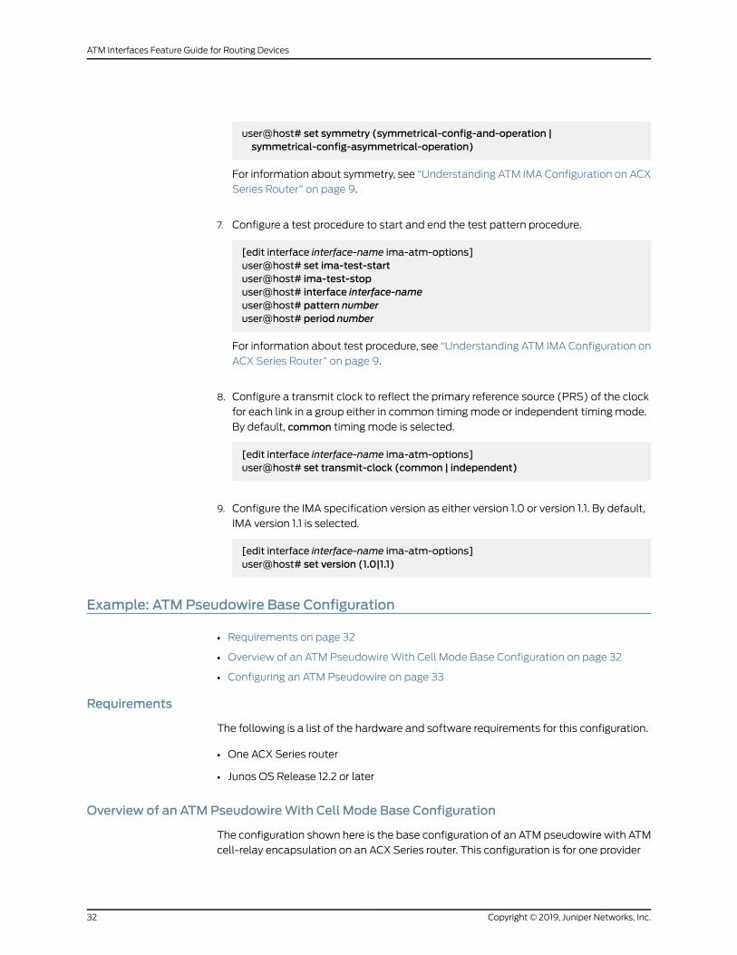
user@host# set symmetry (symmetrical-config-and-operation |symmetrical-config-asymmetrical-operation)
For information about symmetry, see “Understanding ATM IMAConfiguration on ACX
Series Router” on page 9.
7. Configure a test procedure to start and end the test pattern procedure.
[edit interface interface-name ima-atm-options]user@host# set ima-test-startuser@host# ima-test-stopuser@host# interface interface-nameuser@host# pattern numberuser@host# period number
For information about test procedure, see “Understanding ATM IMA Configuration on
ACX Series Router” on page 9.
8. Configure a transmit clock to reflect the primary reference source (PRS) of the clock
for each link in a group either in common timing mode or independent timing mode.
By default, common timing mode is selected.
[edit interface interface-name ima-atm-options]user@host# set transmit-clock (common | independent)
9. Configure the IMA specification version as either version 1.0 or version 1.1. By default,
IMA version 1.1 is selected.
[edit interface interface-name ima-atm-options]user@host# set version (1.0|1.1)
Example: ATMPseudowire Base Configuration
• Requirements on page 32
• Overview of an ATM PseudowireWith Cell Mode Base Configuration on page 32
• Configuring an ATM Pseudowire on page 33
Requirements
The following is a list of the hardware and software requirements for this configuration.
• One ACX Series router
• Junos OS Release 12.2 or later
Overview of an ATMPseudowireWith Cell Mode Base Configuration
The configuration shown here is the base configuration of an ATM pseudowire with ATM
cell-relay encapsulation on an ACX Series router. This configuration is for one provider
Copyright © 2019, Juniper Networks, Inc.32
ATM Interfaces Feature Guide for Routing Devices
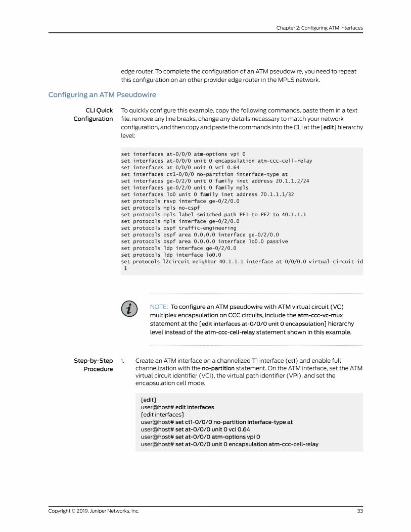
edge router. To complete the configuration of an ATM pseudowire, you need to repeat
this configuration on an other provider edge router in the MPLS network.
Configuring an ATMPseudowire
CLI QuickConfiguration
To quickly configure this example, copy the following commands, paste them in a text
file, remove any line breaks, change any details necessary to match your network
configuration, and then copyandpaste the commands into theCLI at the [edit] hierarchy
level:
set interfaces at-0/0/0 atm-options vpi 0set interfaces at-0/0/0 unit 0 encapsulation atm-ccc-cell-relayset interfaces at-0/0/0 unit 0 vci 0.64set interfaces ct1-0/0/0 no-partition interface-type atset interfaces ge-0/2/0 unit 0 family inet address 20.1.1.2/24set interfaces ge-0/2/0 unit 0 family mplsset interfaces lo0 unit 0 family inet address 70.1.1.1/32set protocols rsvp interface ge-0/2/0.0set protocols mpls no-cspfset protocols mpls label-switched-path PE1-to-PE2 to 40.1.1.1set protocols mpls interface ge-0/2/0.0set protocols ospf traffic-engineeringset protocols ospf area 0.0.0.0 interface ge-0/2/0.0set protocols ospf area 0.0.0.0 interface lo0.0 passiveset protocols ldp interface ge-0/2/0.0set protocols ldp interface lo0.0set protocols l2circuit neighbor 40.1.1.1 interface at-0/0/0.0 virtual-circuit-id 1
NOTE: To configure an ATM pseudowire with ATM virtual circuit (VC)multiplex encapsulation on CCC circuits, include the atm-ccc-vc-mux
statement at the [edit interfaces at-0/0/0 unit 0 encapsulation] hierarchy
level instead of the atm-ccc-cell-relay statement shown in this example.
Step-by-StepProcedure
Create an ATM interface on a channelized T1 interface (ct1) and enable fullchannelization with the no-partition statement. On the ATM interface, set the ATMvirtual circuit identifier (VCI), the virtual path identifier (VPI), and set theencapsulation cell mode.
[edit]
1.
user@host# edit interfaces[edit interfaces]user@host# set ct1-0/0/0 no-partition interface-type atuser@host# set at-0/0/0 unit 0 vci 0.64user@host# set at-0/0/0 atm-options vpi 0user@host# set at-0/0/0 unit 0 encapsulation atm-ccc-cell-relay
33Copyright © 2019, Juniper Networks, Inc.
Chapter 2: Configuring ATM Interfaces

2. Create a Gigabit Ethernet interface and enable MPLS on that interface. Create theloopback (lo0) interface:
[edit interfaces]user@host# set ge-0/2/0 unit 0 family inet address 20.1.1.2/24user@host# set ge-0/2/0 unit 0 family mplsuser@host# set lo0 unit 0 family inet address 70.1.1.1/32
3. Enable the MPLS and RSVP protocols on the MPLS interface—ge-0/2/0.0:
[edit]user@host# edit protocols[edit protocols]user@host# set rsvp interface ge-0/2/0.0user@host# setmpls interface ge-0/2/0.0
4. Configure LDP. If you configure RSVP for a pseudowire, youmust also configureLDP:
[edit protocols]user@host# set protocols ldp interface ge-0/2/0.0user@host# set protocols ldp interface lo0.0
5. Configureapoint-to-point label-switchedpath (LSP)anddisable constrained-pathLSP computation:
[edit protocols]user@host# setmpls label-switched-path PE1-to-PE2 to 40.1.1.1user@host# setmpls no-cspf
6. ConfigureOSPF and enable traffic engineering on theMPLS interface—ge-0/2/0.0,and on the loopback (lo0) interface:
[edit protocols]user@host# set ospf traffic-engineeringuser@host# set ospf area 0.0.0.0 interface ge-0/2/0.0user@host# set ospf area 0.0.0.0 interface lo0.0 passive
7. Uniquely identify a Layer 2 circuit for the ATM pseudowire:
[edit protocols]user@host# set l2circuit neighbor 40.1.1.1 interface at-0/0/0.0 virtual-circuit-id 1
Copyright © 2019, Juniper Networks, Inc.34
ATM Interfaces Feature Guide for Routing Devices

Results
[edit]user@host# showinterfaces { at-0/0/0 { atm-options { vpi 0; } unit 0 { encapsulation atm-ccc-cell-relay; vci 0.64; } } ct1-0/0/0 { no-partition interface-type at; } ge-0/2/0 { unit 0 { family inet { address 20.1.1.2/24; } family mpls; } } lo0 { unit 0 { family inet { address 70.1.1.1/32; } } }}protocols { rsvp { interface ge-0/2/0.0; } mpls { no-cspf; label-switched-path PE1-to-PE2 { to 40.1.1.1; } interface ge-0/2/0.0; } ospf { traffic-engineering; area 0.0.0.0 { interface ge-0/2/0.0; interface lo0.0 { passive; } } } ldp { interface ge-0/2/0.0; interface lo0.0; } l2circuit {
35Copyright © 2019, Juniper Networks, Inc.
Chapter 2: Configuring ATM Interfaces

neighbor 40.1.1.1 { interface at-0/0/0.0 { virtual-circuit-id 1; } } }}
RelatedDocumentation
Pseudowire Overview for ACX Series Universal Metro Routers•
• ATM Pseudowire Overview on page 5
Example: Configuring ATM1 Interfaces
The following configuration is sufficient to get an ATM1 OC3 or OC12 interface up and
running. By default, ATM interfaces use ATM PVC encapsulation.
[edit interfaces]at-fpc/pic/port {atm-options {vpi vpi-identifiermaximum-vcsmaximum-vcs-value;unit 0 { # one unit per VCvci vpi-identifier.vci-identifier;family inet {address local-address {destination address;
}}
}unit 1 { # second VC...
}
ComplexConfigurationExample
[edit interfaces]at-0/0/0 {encapsulation atm-pvc;atm-options {vpi 0maximum-vcs 1200;
}unit 2 {encapsulation atm-snap;inverse-arp;vci 0.80;family inet {mtu 1500;address 192.168.0.3/32 {destination 192.168.0.1;
}}
}
Copyright © 2019, Juniper Networks, Inc.36
ATM Interfaces Feature Guide for Routing Devices

unit 3 {encapsulation atm-snap;vci 0.32;oam-period 60;family inet {mtu 1500;address 192.168.4.3/32 {destination 192.168.4.2;
}}
}}at-0/2/0 {encapsulation atm-pvc;atm-options {vpi 0maximum-vcs 1200;
}unit 2 {encapsulation atm-snap;inverse-arp;vci 0.82;family inet {mtu 1500;address 192.168.5.3/32 {destination 192.168.5.2;
}}
}}at-0/3/0 {encapsulation atm-pvc;atm-options {vpi 0maximum-vcs 1200;
}unit 140 {encapsulation atm-snap;multipoint;family inet {address 192.168.7.4/24 {multipoint-destination 192.168.7.5;vci 0.100;inverse-arp;
}}
}}at-7/3/0 {encapsulation atm-pvc;atm-options {vpi 0maximum-vcs 1200;
}unit 0 {encapsulation atm-snap;vci 0.32;family inet {
37Copyright © 2019, Juniper Networks, Inc.
Chapter 2: Configuring ATM Interfaces

address 192.168.12.3/32 {destination 192.168.12.2;
}}
}}
RelatedDocumentation
ATM Interfaces Overview on page 3•
• Configuring the MaximumNumber of ATM1 VCs on a VP on page 46
• Displaying the Status of a Specific ATM1 Interface on page 180
• Verifying the Configuration of an ATM1 Interface on page 170
• Displaying ATM1 and ATM2 Alarms and Errors on page 225
Example: Configuring ATM2 IQ Interfaces
Configure VP tunnel-shaping and OAM F4 on an ATM2 IQ interface:
interfaces {at-5/2/0 {atm-options {vpi 0 {shaping {vbr peak 10m sustained 6m burst 12;
}oam-period 10;oam-liveness {up-count 6;down-count 5;
}}vpi 4 {shaping {vbr peak 7m sustained 4m burst 24;
}}vpi 5 {oam-period 10;oam-liveness {up-count 6;down-count 5;
}}vpi 6;
}unit 0 {vci 0.128;transmit-weight 20;family inet {address 192.168.9.225/32 {
Copyright © 2019, Juniper Networks, Inc.38
ATM Interfaces Feature Guide for Routing Devices
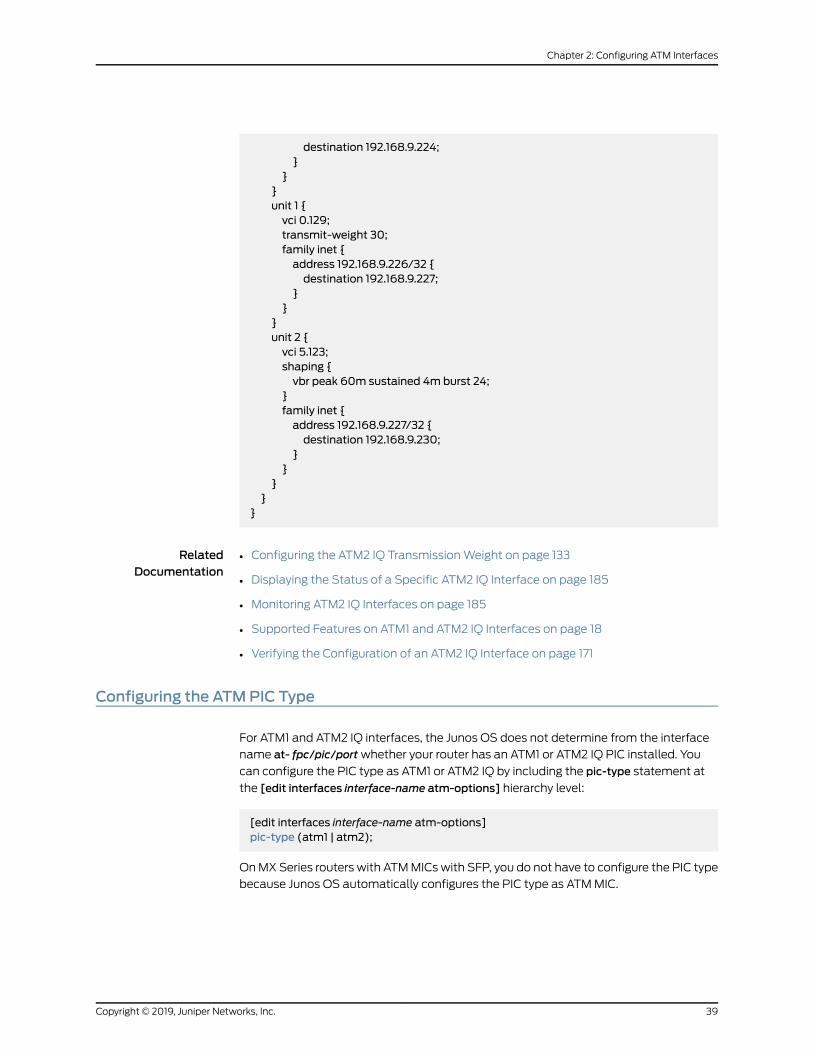
destination 192.168.9.224;}
}}unit 1 {vci 0.129;transmit-weight 30;family inet {address 192.168.9.226/32 {destination 192.168.9.227;
}}
}unit 2 {vci 5.123;shaping {vbr peak 60m sustained 4m burst 24;
}family inet {address 192.168.9.227/32 {destination 192.168.9.230;
}}
}}
}
RelatedDocumentation
Configuring the ATM2 IQ TransmissionWeight on page 133•
• Displaying the Status of a Specific ATM2 IQ Interface on page 185
• Monitoring ATM2 IQ Interfaces on page 185
• Supported Features on ATM1 and ATM2 IQ Interfaces on page 18
• Verifying the Configuration of an ATM2 IQ Interface on page 171
Configuring the ATMPIC Type
For ATM1 and ATM2 IQ interfaces, the Junos OS does not determine from the interface
name at- fpc/pic/portwhether your router has an ATM1 or ATM2 IQ PIC installed. You
can configure the PIC type as ATM1 or ATM2 IQ by including the pic-type statement at
the [edit interfaces interface-name atm-options] hierarchy level:
[edit interfaces interface-name atm-options]pic-type (atm1 | atm2);
OnMXSeries routers with ATMMICswith SFP, you do not have to configure the PIC type
because Junos OS automatically configures the PIC type as ATMMIC.
39Copyright © 2019, Juniper Networks, Inc.
Chapter 2: Configuring ATM Interfaces
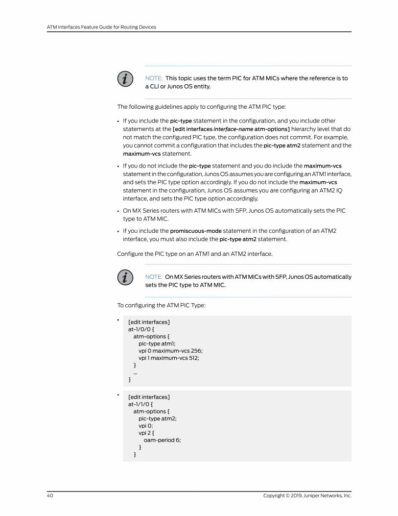
NOTE: This topic uses the term PIC for ATMMICs where the reference is toa CLI or Junos OS entity.
The following guidelines apply to configuring the ATM PIC type:
• If you include the pic-type statement in the configuration, and you include other
statements at the [edit interfaces interface-name atm-options] hierarchy level that do
not match the configured PIC type, the configuration does not commit. For example,
you cannot commit a configuration that includes the pic-type atm2 statement and the
maximum-vcs statement.
• If you do not include the pic-type statement and you do include themaximum-vcs
statement in theconfiguration, JunosOSassumesyouareconfiguringanATM1 interface,
and sets the PIC type option accordingly. If you do not include themaximum-vcs
statement in the configuration, Junos OS assumes you are configuring an ATM2 IQ
interface, and sets the PIC type option accordingly.
• OnMX Series routers with ATMMICs with SFP, Junos OS automatically sets the PIC
type to ATMMIC.
• If you include the promiscuous-mode statement in the configuration of an ATM2
interface, youmust also include the pic-type atm2 statement.
Configure the PIC type on an ATM1 and an ATM2 interface.
NOTE: OnMXSeries routerswithATMMICswithSFP, JunosOSautomaticallysets the PIC type to ATMMIC.
To configuring the ATM PIC Type:
• [edit interfaces]at-1/0/0 {atm-options {pic-type atm1;vpi 0maximum-vcs 256;vpi 1 maximum-vcs 512;
}...
}
• [edit interfaces]at-1/1/0 {atm-options {pic-type atm2;vpi 0;vpi 2 {oam-period 6;
}}
Copyright © 2019, Juniper Networks, Inc.40
ATM Interfaces Feature Guide for Routing Devices
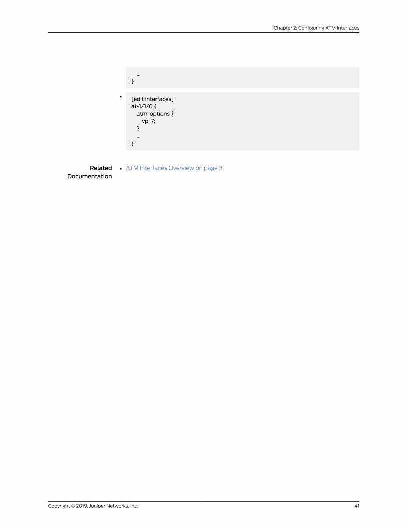
...}
• [edit interfaces]at-1/1/0 {atm-options {vpi 7;
}...
}
RelatedDocumentation
ATM Interfaces Overview on page 3•
41Copyright © 2019, Juniper Networks, Inc.
Chapter 2: Configuring ATM Interfaces

Configuring ATMCell-Relay PromiscuousMode
Copyright © 2019, Juniper Networks, Inc.42
ATM Interfaces Feature Guide for Routing Devices

For ATM1 and ATM2 IQ with atm-ccc-cell-relay encapsulation, you canmap all incoming
cells fromeither an interface port or a virtual path (VP) to a single LSPwithout restricting
the VCI number. Promiscuous mode allows you to map traffic from all 65,535 VCIs to a
single LSP, or from all 256 VPIs to a single LSP.
Tomap incoming traffic from a port or VC to an LSP, include the promiscuous-mode
statement at the [edit interfaces interface-name atm-options] hierarchy level:
[edit interfaces interface-name]atm-options {promiscuous-mode {vpi vpi-identifier;
}}
You can includemultiple vpi statements in the configuration.
To enable all VCIs in a VPI to open in ATM CCC cell-relay mode, youmust also map the
logical interface to a VPI by including the vpi statement in the logical interface
configuration:
vpi vpi-identifier;
You can include this statement at the following hierarchy levels:
• [edit interfaces interface-name unit logical-unit-number]
• [edit logical-systems logical-system-name interfaces interface-name unit
logical-unit-number]
Also, note the following:
• For promiscuous mode, youmust configure the port with atm-ccc-cell-relay
encapsulation.
• For ATM1 PICs and ATM2 IQ PICs, changing modes between promiscuous and
nonpromiscuous causes all physical interfaces to be deleted and re-added.
• For ATM1 PICs, and ATM2 IQ PICs, when you configure promiscuousmode, you cannot
configure VCIs.
• For ATM1 PICs, if you configure one port in port mode, all ports on the PIC operate in
port mode. Likewise if you configure one logical interface in VPI mode, all logical
interfaces on the PICmust operate in VPI mode.
• For ATM2 IQ PICs, you can configure one ormore logical interfaces in VPI promiscuous
mode, and the other logical interfaces with any ATM encapsulation.
• For ATM2 IQ PICs, when you configure promiscuous mode, youmust also include the
pic-type atm2 statement. For more information, see “Configuring the ATM PIC Type”
on page 39.
• For ATM2 IQmultiport PICs, you can configure one or more ports in port promiscuous
mode, and the other ports with any ATM encapsulation.
43Copyright © 2019, Juniper Networks, Inc.
Chapter 2: Configuring ATM Interfaces

• For interfaces that are configured for cell-relaypromiscuous virtual path identifier (VPI)
mode, the show interfaces command output does not showOAM F4 cell statistics.
To configure ATM Cell-Relay Promiscuous Mode:
1. Use the following statements to configure the port-promiscuous mode:
[edit interfaces]at-0/2/1 {encapsulation atm-ccc-cell-relay; # at the physical interface level onlyatm-options {pic-type atm2;promiscuous-mode;
}unit 0 {allow-any-vci;
}}
2. Use the following statements to configure the VP-Promiscuous mode:
[edit interfaces]at-0/2/0 {atm-options {pic-type atm2;promiscuous-mode {vpi 0;vpi 1;
}vpi 2;vpi 3;
}unit 0 {encapsulation atm-ccc-cell-relay; # at the logical interface level onlyvpi 0;
}unit 1 {encapsulation atm-ccc-cell-relay;vpi 1;
}unit 2 {encapsulation atm-snap;vci 2.100;
}unit 3 {encapsulation atm-vc-mux;vci 3.100;
}}
3. Tomap incoming traffic from a port to an LSP, include the allow-any-vci statement
at the [edit interfaces interface-name unit 0] hierarchy level. When you include the
Copyright © 2019, Juniper Networks, Inc.44
ATM Interfaces Feature Guide for Routing Devices

allow-any-vci statement, you cannot configure other logical interfaces in the same
physical interface. Next, youmust map unit 0 to an LSP using the CCC connection.
[edit interfaces at-1/2/0]encapsulation atm-ccc-cell-relay;atm-options {promiscuous-mode;
}unit 0 {allow-any-vci;
}
4. Tomap unit 0 to an LSP:
protocols {connections {remote-interface-switch router-a-router-c {interface at-1/2/0.0;
}lsp-switch router-a-router-c {transmit-lsp lsp1receive-lsp lsp2;
}}
}
5. Tomap a VPI to an LSP, youmust define the allowed VPIs. You can configure one or
more logical interfaces, eachmapped to a different VPI. You can then route traffic
from each of these interfaces to different LSPs.
[edit interfaces at-1/1/0]encapsulation atm-ccc-cell-relay;atm-options {pic-type atm1;promiscuous-mode {vpi 10;vpi 20;
}}unit 0 {encapsulation atm-ccc-cell-relay;vpi 10;
}unit 1 {encapsulation atm-ccc-cell-relay;vpi 20;
}[edit interfaces at-3/1/0]encapsulation atm-ccc-cell-relay;atm-options {pic-type atm2;promiscuous-mode {
45Copyright © 2019, Juniper Networks, Inc.
Chapter 2: Configuring ATM Interfaces

vpi 10;vpi 20;
}}unit 0 {encapsulation atm-ccc-cell-relay;vpi 10;
}unit 1 {encapsulation atm-ccc-cell-relay;vpi 20;
}[edit protocols]mpls {connections {interface-switch router-a-router-c {interface at-1/1/0.0;interface at-3/1/0.0;
}interface-switch router-a-router-d {interface at-1/1/0.1;interface at-3/1/0.1;
}}
}
RelatedDocumentation
ATM Interfaces Overview on page 3•
Configuring theMaximumNumber of ATM1 VCs on a VP
For ATM1 interfaces, youmust configure the maximum number of virtual circuits (VCs)
allowedonavirtual path (VP) so that sufficientmemoryon theATM1PICcanbeallocated
for each VC.
To configure the highest-numbered VCs on a VP, include themaximum-vcs and vpi
statements at the [edit interfaces interface-name atm-options] hierarchy level:
[edit interfaces interface-name atm-options]vpi vpi-identifier {maximum-vcsmaximum-vcs;
}
The VP identifier can be a value from 0 through 255. For most interfaces, you can define
amaximum of 4090 VCs per interface, and some interfaces have higher limits.
Promiscuous mode removes these limits. For more information, see “Configuring ATM
Cell-Relay Promiscuous Mode” on page 42.
All VPIs that you configure in the atm-options statement are stored in a single table. If
youmodify the VPIs—for example, by editing them in configurationmode or by issuing a
Copyright © 2019, Juniper Networks, Inc.46
ATM Interfaces Feature Guide for Routing Devices

loadoverride command—all VCs on the interface are closed and then reopened, resulting
in a temporary loss of connectivity for all the VCs on the interface.
You can also include some of the statements in the sonet-options statement to set
SONET/SDH parameters on ATM interfaces, as described in “Configuring SONET/SDH
Parameters on ATM Interfaces” on page 50.
Configuring Communication with Directly Attached ATMSwitches and Routers
ForATM1andATM2 IQ interfaces, youcanconfigurecommunicationwithdirectlyattached
ATMswitchesand routers toenablequeryingof the IPaddressesandswitchportnumbers.
You query the switch or router by entering the following show command:
user@host> show ilmi interface interface-name
The router uses VC 0.16 to communicate with the ATM switch or router.
To configure communication between the router and its directly attached ATM switches
and routers, include the ilmi statementat the [edit interfaces interface-nameatm-options]
hierarchy level:
[edit interfaces interface-name atm-options]ilmi;
For example, to configure Communication with Directly Attached ATM Switches and
Routers:
1. Enable an interface to communicate directly with an ATM switch or router:
[edit interfaces]at-0/1/0 {atm-options {vpi 0;ilmi;
}unit 0 {vci 0.120;family inet {address 10.33.33.1/30;
}}
}
RelatedDocumentation
ilmi on page 278•
47Copyright © 2019, Juniper Networks, Inc.
Chapter 2: Configuring ATM Interfaces

Enabling ILMI for Cell Relay
The JunosOS supports standard AAL5 and three Layer 2 circuit transportmodes: Layer 2
circuit AAL5, Layer 2 circuit cell-relay, and Layer 2 circuit trunk transport mode.
Integrated localmanagement interface (ILMI) is supported on standardAAL5 interfaces,
regardless of encapsulation. To enable ILMI on interfaces with cell-relay encapsulation,
youmust configure an ATM2 IQ PIC to use Layer 2 circuit trunk transport mode. ILMI is
not supported with cell-relay encapsulation when the ATM2 IQ PIC is configured with
Layer 2 AAL5 or Layer 2 circuit cell-relay transport mode, as shown in as shown in
Table 10 on page 48.
Layer 2 circuit cell-relay trunk mode is not supported on ATMOC48 PICs.
Table 10: ILMI Support by Encapsulation Type
ILMI SupportEncapsulation Type
YesStandard AAL5, with any encapsulation type
NoLayer 2 circuit AAL5mode
NoLayer 2 circuit cell-relay mode
YesLayer 2 circuit trunk mode
For more information about Layer 2 circuit transport modes, see “Configuring Layer 2
Circuit Transport Mode” on page 54.
1. To configure ILMI on an interface with cell-relay encapsulation, include the following
statements:
[edit chassis fpc slot-number pic pic-number]atm-l2circuit-mode trunk trunk;[edit interfaces at-fpc/pic/port]encapsulation atm-ccc-cell-relay;atm-options {ilmi;pic-type atm2;
}unit logical-unit-number {trunk-id number;
}
For more information about ILMI, see “Configuring Communication with Directly
Attached ATM Switches and Routers” on page 47.
2. On an ATM2 IQ PIC with Layer 2 circuit trunk transport mode, enable ILMI on an
interface with cell-relay encapsulation:
Copyright © 2019, Juniper Networks, Inc.48
ATM Interfaces Feature Guide for Routing Devices

[edit chassis]fpc 0 {pic 1 {atm-l2circuit-mode trunk uni;
}}[edit interfaces]at-0/0/0 {encapsulation atm-ccc-cell-relay;atm-options {pic-type atm2;ilmi;
}}
RelatedDocumentation
ATM Interfaces Overview on page 3•
Configuring E3 and T3 Parameters on ATM Interfaces
ForATM1andATM2 IQ interfaces, youcanconfigureATME3andT3 interfacesby including
the following statements at the [edit interfaces at-fpc/pic/port ] hierarchy level:
[edit interfaces at-fpc/pic/port]e3-options {atm-encapsulation (direct | plcp);buildout feet;framing (g.751 | g.832);loopback (local | remote);(payload-scrambler | no-payload-scrambler);
}t3-options {atm-encapsulation (direct | plcp);buildout feet;(cbit-parity | no-cbit-parity);loopback (local | payload | remote);(payload-scrambler | no-payload-scrambler);
}
The following options and default values differ from those described in E3 Interfaces
Overview and T3 Interfaces Overview:
• atm-encapsulation—PLCP is thedefault value.TheE3 line-formatoptiong.832 supports
the direct ATM-encapsulation option only.
• buildout—The default value is 10 feet. The number of feet can be any integer value.
The range is from 0 through 450 feet (about 137 meters).
• cbit-parity—The default option is to enable cbit parity.
• framing—There is no default option for E3 interfaces; T3 interfaces use the
cbit-parity statement in place of the framing statement.
49Copyright © 2019, Juniper Networks, Inc.
Chapter 2: Configuring ATM Interfaces
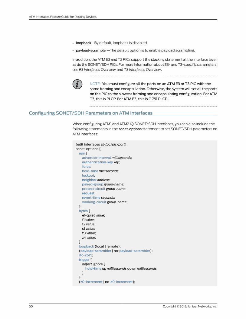
• loopback—By default, loopback is disabled.
• payload-scrambler—The default option is to enable payload scrambling.
In addition, theATME3andT3PICs support the clocking statement at the interface level,
asdo theSONET/SDHPICs. Formore informationaboutE3-andT3-specificparameters,
see E3 Interfaces Overview and T3 Interfaces Overview.
NOTE: Youmust configure all the ports on an ATM E3 or T3 PIC with thesame framing andencapsulation.Otherwise, the systemwill set all the portson the PIC to the slowest framing and encapsulating configuration. For ATMT3, this is PLCP. For ATM E3, this is G.751 PLCP.
Configuring SONET/SDH Parameters on ATM Interfaces
When configuring ATM1 and ATM2 IQ SONET/SDH interfaces, you can also include the
following statements in the sonet-options statement to set SONET/SDH parameters on
ATM interfaces:
[edit interfaces at-fpc/pic/port]sonet-options {aps {advertise-intervalmilliseconds;authentication-key key;force;hold-timemilliseconds;lockout;neighbor address;paired-group group-name;protect-circuit group-name;request;revert-time seconds;working-circuit group-name;
}bytes {e1-quiet value;f1 value;f2 value;s1 value;z3 value;z4 value;
}loopback (local | remote);(payload-scrambler | no-payload-scrambler);rfc-2615;trigger {defect ignore {hold-time upmilliseconds downmilliseconds;
}}(z0-increment | no-z0-increment);
Copyright © 2019, Juniper Networks, Inc.50
ATM Interfaces Feature Guide for Routing Devices
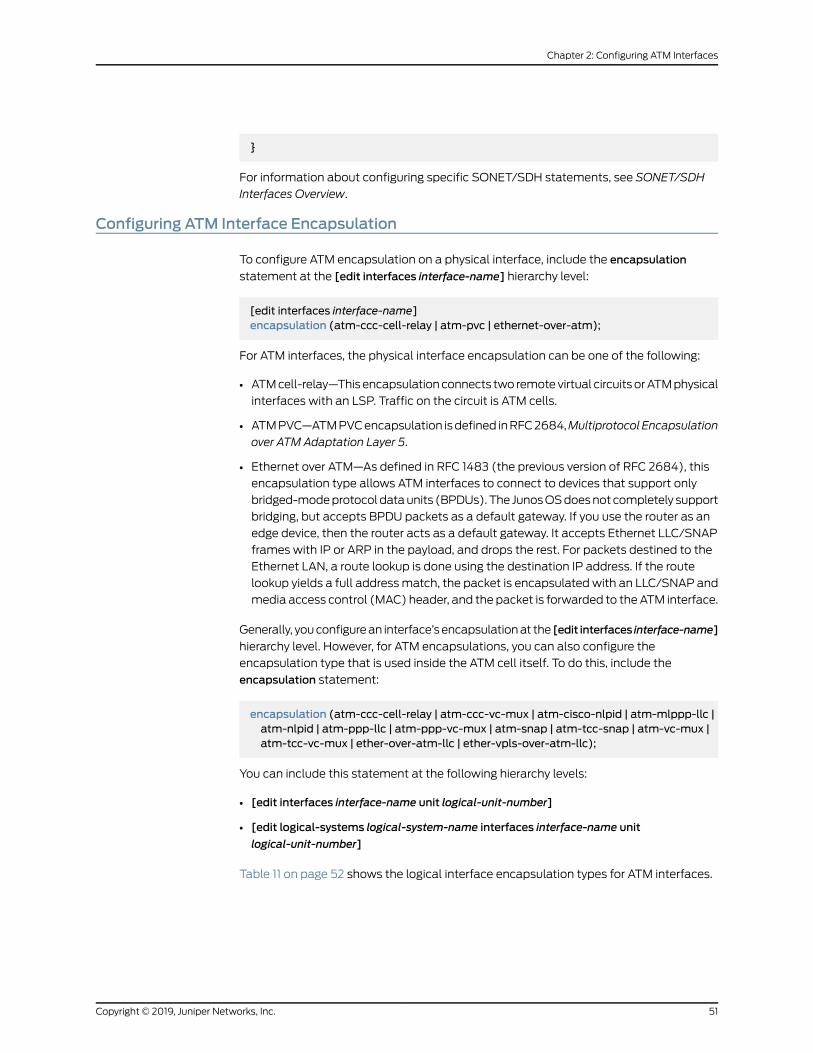
}
For information about configuring specific SONET/SDH statements, see SONET/SDH
Interfaces Overview.
Configuring ATM Interface Encapsulation
To configure ATM encapsulation on a physical interface, include the encapsulation
statement at the [edit interfaces interface-name] hierarchy level:
[edit interfaces interface-name]encapsulation (atm-ccc-cell-relay | atm-pvc | ethernet-over-atm);
For ATM interfaces, the physical interface encapsulation can be one of the following:
• ATMcell-relay—Thisencapsulationconnects two remotevirtual circuitsorATMphysical
interfaces with an LSP. Traffic on the circuit is ATM cells.
• ATMPVC—ATMPVCencapsulation isdefined inRFC2684,MultiprotocolEncapsulation
over ATM Adaptation Layer 5.
• Ethernet over ATM—As defined in RFC 1483 (the previous version of RFC 2684), this
encapsulation type allows ATM interfaces to connect to devices that support only
bridged-modeprotocoldataunits (BPDUs).The JunosOSdoesnotcompletely support
bridging, but accepts BPDU packets as a default gateway. If you use the router as an
edge device, then the router acts as a default gateway. It accepts Ethernet LLC/SNAP
frames with IP or ARP in the payload, and drops the rest. For packets destined to the
Ethernet LAN, a route lookup is done using the destination IP address. If the route
lookup yields a full addressmatch, the packet is encapsulated with an LLC/SNAP and
media access control (MAC) header, and the packet is forwarded to theATM interface.
Generally, youconfigurean interface’s encapsulationat the [edit interfaces interface-name]
hierarchy level. However, for ATM encapsulations, you can also configure the
encapsulation type that is used inside the ATM cell itself. To do this, include the
encapsulation statement:
encapsulation (atm-ccc-cell-relay | atm-ccc-vc-mux | atm-cisco-nlpid | atm-mlppp-llc |atm-nlpid | atm-ppp-llc | atm-ppp-vc-mux | atm-snap | atm-tcc-snap | atm-vc-mux |atm-tcc-vc-mux | ether-over-atm-llc | ether-vpls-over-atm-llc);
You can include this statement at the following hierarchy levels:
• [edit interfaces interface-name unit logical-unit-number]
• [edit logical-systems logical-system-name interfaces interface-name unit
logical-unit-number]
Table 11 on page 52 shows the logical interface encapsulation types for ATM interfaces.
51Copyright © 2019, Juniper Networks, Inc.
Chapter 2: Configuring ATM Interfaces

Table 11: ATM Logical Interface Encapsulation Types
CommentsEncapsulation Types
This encapsulation type connects two remote virtual circuits or ATMphysical interfaceswith an LSP.
This encapsulation type carries traffic in ATM cells.
When you use this encapsulation type, you can configure the ccc family only.
ATM CCC cell relay
This encapsulation type is for CCC circuits.
When you use this encapsulation type, you can configure the ccc family only.
ATM CCC VCmultiplex
When you use this encapsulation type, you can configure the inet family only.ATMnetwork layer protocol identifier(NLPID)
ATM SNAP
When you use this encapsulation type, you can configure the tcc family only.ATM SNAP encapsulation ontranslational cross-connect (TCC)circuits
When you use this encapsulation type, you can configure the inet family only.ATM VCmultiplex
When you use this encapsulation type, you can configure the tcc family only.ATM VCmultiplex on TCC circuits
In this mode, the incoming 1 to 8 cells are packaged into a single packet and forwardedto the LSP. To configure CAM, include the atm-cell-relay-accumulation statement atthe [edit chassis fpc slot-number pic pic-number] hierarchy level.
This encapsulation type is for ATM1 interfaces only.
For more information about CAM, see the Junos OS Administration Library.
Cell-relayaccumulationmode(CAM)
When you use this encapsulation type, you can configure the inet family only.Cisco ATMNLPID
This encapsulation type is for interfaces that carry IPv4 traffic.
When you use this encapsulation type, you cannot configure point-to-multipointinterfaces.
Ethernet over ATM
This encapsulation type enables aVPLS instance to support bridging betweenEthernetinterfaces and ATM interfaces, as described in RFC 2684.
Use this encapsulation type to support IEEE 802.1p classification binding on ATM VCs.
This encapsulation type is for ATM2 IQ interfaces only.
When you use this encapsulation type, you cannot configure point-to-multipointinterfaces.
Ethernet VPLS over ATM
This encapsulation type is for ATM2 IQ interfaces only.
Whenyouuse this encapsulation type, your routermustbeequippedwithaLinkServicesor Voice Services PIC.
Multilink PPP over AAL5 LLC
Copyright © 2019, Juniper Networks, Inc.52
ATM Interfaces Feature Guide for Routing Devices

Table 11: ATM Logical Interface Encapsulation Types (continued)
CommentsEncapsulation Types
This encapsulation type is for ATM2 IQ interfaces only.
When you use this encapsulation type, you cannot configure point-to-multipointinterfaces.
PPP over AAL5 LLC
This encapsulation type is for ATM2 IQ interfaces only.
When you use this encapsulation type, you cannot configure point-to-multipointinterfaces.
PPP over AAL5multiplex
53Copyright © 2019, Juniper Networks, Inc.
Chapter 2: Configuring ATM Interfaces

Configuring Layer 2 Circuit Transport Mode
Copyright © 2019, Juniper Networks, Inc.54
ATM Interfaces Feature Guide for Routing Devices
On ATM2 IQ interfaces only, you can configure Layer 2 circuit cell-relay, Layer 2 circuit
AAL5, or Layer 2 circuit trunk transport mode.
Layer 2 circuit cell-relay and Layer 2 circuit AAL5 are defined in Internet draft
draft-martini-l2circuit-encap-mpls-07.txt, Encapsulation Methods for Transport of Layer
2 Frames Over IP and MPLS Networks (expires December 2004).
Layer 2 circuit cell-relay and Layer 2 circuit AAL5 transportmodes allow you to sendATM
cells between ATM2 IQ interfaces across a Layer 2 circuit-enabled network. Layer 2
circuits are designed to transport Layer 2 frames between PE routers across an
LDP-signaled MPLS backbone. You use Layer 2 circuit AAL5 transport mode to send
AAL5 segmentation and reassembly protocol data units (SAR-PDUs) over the Layer 2
circuit.
A trunk is a collection of ATM VPs. Layer 2 circuit trunk transport mode allows you to
send ATM cells over MPLS trunking.
By default, ATM2 IQ PICs are in standard AAL5 transport mode. Standard AAL5 allows
multiple applications to tunnel the protocol data units of their Layer 2 protocols over an
ATM virtual circuit. Encapsulation of these Layer 2 protocol data units allows a number
of these emulated virtual circuits to be carried in a single tunnel. Protocol data units are
segmentedat oneendof the tunnel and reassembledat theother end. The ingress router
reassembles the protocol data units received from the incoming VC and transports each
PDU as a single packet.
In contrast, Layer 2 circuit cell-relay and Layer 2 circuit AAL5 transport modes accept a
stream of ATM cells, convert these to an encapsulated Layer 2 format, then tunnel them
overanMPLSor IPbackbone,wherea similarly configured router segments thesepackets
back into a stream of ATM cells, to be forwarded to the virtual circuit configured for the
far-end router.
In Layer 2 circuit cell-relay transport mode, ATM cells are bundled together and
transported in packet form to the far-end router, where they are segmented back into
individual ATM cells and forwarded to the ATM virtual circuit configured for the far-end
router.
NOTE: When you configure the cell-bundle-size statement at the [edit
interfaces at -fpc/pic/port atm-options] hierarchy level is 1 and the
atm-ccc-cell-relay trunk statement is included at the [edit interfaces
interface-name encapsulation] hierarchy level, ATM cells are not bundled.
Each ATM cell is forwarded as a single MPLS packet.
The uses for the four transport modes are defined as follows:
• To tunnel IP packets over an ATM backbone, use the default standard AAL5 transport
mode.
• To tunnel a stream of AAL5-encoded ATM SAR-PDUs over an MPLS or IP backbone,
use Layer 2 circuit AAL5 transport mode.
55Copyright © 2019, Juniper Networks, Inc.
Chapter 2: Configuring ATM Interfaces

• To tunnel a stream of ATM cells over an MPLS or IP backbone, use Layer 2 circuit
cell-relay transport mode.
• To transport ATMcells over anMPLS core network that is implemented between other
vendors’ switches or routers, use Layer 2 circuit trunk transport mode.
NOTE: You can transport AAL5-encoded traffic with Layer 2 circuitcell-relay transportmode,becauseLayer2circuit cell-relay transportmodeignores the encoding of the cell data presented to the ingress interface.
When you configure AAL5mode Layer 2 circuits, the control word carriescell loss priority (CLP) information by default.
The Layer 2 circuit trunk transport mode is not supported on the ATM2 IQOC48c/STM16 PIC.
To configure Layer 2 circuit AAL5, Layer 2 circuit cell-relay, or Layer 2 circuit trunk mode,
youmust perform the following tasks:
1. Identify the interfaceasanATM2 IQ interfaceby including thepic-typeatm2 statement
at the [edit interfaces at-fpc/pic/port atm-options] hierarchy level:
[edit interfaces at-fpc/pic/port atm-options]pic-type atm2;
2. Include the atm-l2circuit-mode statement at the [edit chassis fpc slot-number pic
pic-number] hierarchy level, specifying aal5, cell, or trunk:
[edit chassis fpc slot-number pic pic-number]atm-l2circuit-mode (aal5 | cell | trunk trunk );[edit chassis]
By default, the trunk mode uses user-to-network interface (UNI) mode. The trunk
option canbeUNI or network-to-network interface (NNI). Formore informationabout
UNI and NNI, see the Junos OS VPNs Library for Routing Devices.
Transport mode is per PIC, not per port. If you do not include the atm-l2circuit-mode
statement in the configuration, the ATM2 IQPIC uses standard AAL5 transportmode.
If you configure Layer 2 circuit cell-relay, Layer 2 circuit AAL5 transportmode, or Layer
2 circuit trunk mode, the entire ATM2 PIC uses the configured transport mode.
3. For Layer 2 circuit trunk mode only, youmust also configure a trunk identification
number by including the trunk-id statement:
trunk-id number;
You can include this statement at the following hierarchy levels:
• [edit interfaces interface-name unit logical-unit-number]
Copyright © 2019, Juniper Networks, Inc.56
ATM Interfaces Feature Guide for Routing Devices

• [edit logical-systemslogical-system-name interfaces interface-name unit
logical-unit-number]
The trunk identification number can be from 0 through 31; each trunk on an interface
must have a unique trunk ID. When you associate a trunk ID number with a logical
interface, you are in effect specifying the interfaces that are allowed to send ATM
traffic over an LSP. ForUNImode, the trunk ID range is from0 through 7. ForNNImode,
the trunk ID range is from 0 through 31. Trunk IDs on connecting trunks do not need
to be the same.
For informationaboutproportional bandwidth sharing in trunkmode, see “Configuring
Layer 2 Circuit Trunk Mode Scheduling Overview” on page 76.
For example:
In Figure 3 on page 57, Router A is a local PE router. Router B is a remote PE router.Both Juniper Networks routers have Layer 2 circuit cell-relay capability. You configurean ATMphysical interface on Router A in Layer 2 circuit trunkmode and specify trunksthat are allowed to send traffic over the LSP. As a cell is received on this interface, itis classifiedusing theCoSbits in thecell header, andencapsulatedasa labeledpacket.It is then queued on one of the outgoing queues according to its classification andsent over the LSP to Router B. At Router B, the packet label is removed and the rawcell is put on one of the queues of the ATM interface and forwarded to the secondATM switch. To carry the CoS information and CLP of the cell over the network, theCoSandCLPbits are copied into the EXPbits of theMPLS label. This CoS informationis used to select the output queues. Using EPD profiles, the CLP is used to determinewhether the cell should be dropped.
For more information about ATM CoS capability, see “ATM2 IQ VC Tunnel CoS
Components Overview” on page 117.
Figure 3: Layer 2 Circuit Trunk Topology
[edit chassis]fpc 0 {pic 1 {atm-l2circuit-mode trunk uni;
}}[edit interfaces]at-0/0/0 {encapsulation atm-ccc-cell-relay;atm-options {pic-type atm2;ilmi;
}unit 0 {
57Copyright © 2019, Juniper Networks, Inc.
Chapter 2: Configuring ATM Interfaces

trunk-id 0;epd-threshold 10240;
}unit 1 {trunk-id 1;epd-threshold 10240;
}unit 2 {trunk-id 2;epd-threshold 10240;
}unit 3 {trunk-id 3;epd-threshold 10240;
}unit 4 {trunk-id 4;epd-threshold 10240;
}unit 5 {trunk-id 5;epd-threshold 10240;
}unit 6 {trunk-id 6;epd-threshold 10240;
}unit 7 {trunk-id 7;epd-threshold 10240;
}}so-3/0/0 {mtu 9192;unit 0 {family inet {address 10.0.1.1/24;
}family mpls;
}}lo0 {unit 0 {family inet {address 172.16.0.1/32;address 10.255.245.1/32;
}}
}[edit protocols]rsvp {interface all;
}mpls {interface all;
Copyright © 2019, Juniper Networks, Inc.58
ATM Interfaces Feature Guide for Routing Devices

}ldp {interface all;
}ospf {traffic-engineering;reference-bandwidth 4g;area 0.0.0.0 {interface all;interface fxp0.0 {disable;
}}
}l2circuit {neighbor 10.255.245.2 {interface at-0/1/0.0 {virtual-circuit-id 100;
}interface at-0/1/0.1 {virtual-circuit-id 101;
}interface at-0/1/0.2 {virtual-circuit-id 102;
}interface at-0/1/0.3 {virtual-circuit-id 103;
}interface at-0/1/0.4 {virtual-circuit-id 104;
}interface at-0/1/0.5 {virtual-circuit-id 105;
}interface at-0/1/0.6 {virtual-circuit-id 106;
}interface at-0/1/0.7 {virtual-circuit-id 107;
}}
}
[edit chassis]fpc 0 {pic 1 {atm-l2circuit-mode trunk uni;
}}[edit interfaces]at-0/0/1 {encapsulation atm-ccc-cell-relay;atm-options {pic-type atm2;
59Copyright © 2019, Juniper Networks, Inc.
Chapter 2: Configuring ATM Interfaces

}unit 0 {trunk-id 0;epd-threshold 10240;
}unit 1 {trunk-id 1;epd-threshold 10240;
}unit 2 {trunk-id 2;epd-threshold 10240;
}unit 3 {trunk-id 3;epd-threshold 10240;
}unit 4 {trunk-id 4;epd-threshold 10240;
}unit 5 {trunk-id 5;epd-threshold 10240;
}unit 6 {trunk-id 6;epd-threshold 10240;
}unit 7 {trunk-id 7;epd-threshold 10240;
}}so-3/0/1 {mtu 9192;unit 0 {family inet {address 10.0.1.2/24;
}family mpls;
}}lo0 {unit 0 {family inet {address 172.16.0.1/32;address 10.255.245.2/32;
}}
}[edit protocols]rsvp {interface all;
}
Copyright © 2019, Juniper Networks, Inc.60
ATM Interfaces Feature Guide for Routing Devices
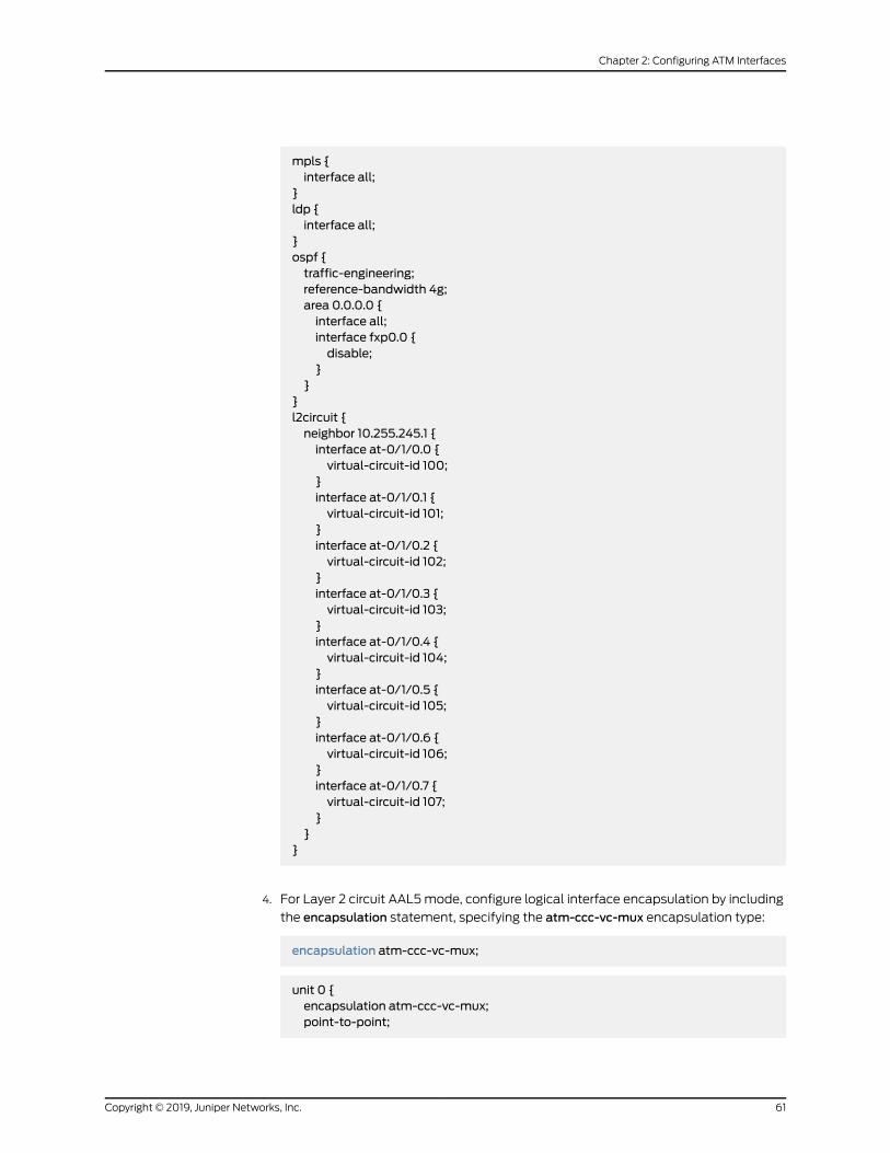
mpls {interface all;
}ldp {interface all;
}ospf {traffic-engineering;reference-bandwidth 4g;area 0.0.0.0 {interface all;interface fxp0.0 {disable;
}}
}l2circuit {neighbor 10.255.245.1 {interface at-0/1/0.0 {virtual-circuit-id 100;
}interface at-0/1/0.1 {virtual-circuit-id 101;
}interface at-0/1/0.2 {virtual-circuit-id 102;
}interface at-0/1/0.3 {virtual-circuit-id 103;
}interface at-0/1/0.4 {virtual-circuit-id 104;
}interface at-0/1/0.5 {virtual-circuit-id 105;
}interface at-0/1/0.6 {virtual-circuit-id 106;
}interface at-0/1/0.7 {virtual-circuit-id 107;
}}
}
4. For Layer 2 circuit AAL5mode, configure logical interface encapsulation by including
the encapsulation statement, specifying the atm-ccc-vc-mux encapsulation type:
encapsulation atm-ccc-vc-mux;
unit 0 {encapsulation atm-ccc-vc-mux;point-to-point;
61Copyright © 2019, Juniper Networks, Inc.
Chapter 2: Configuring ATM Interfaces
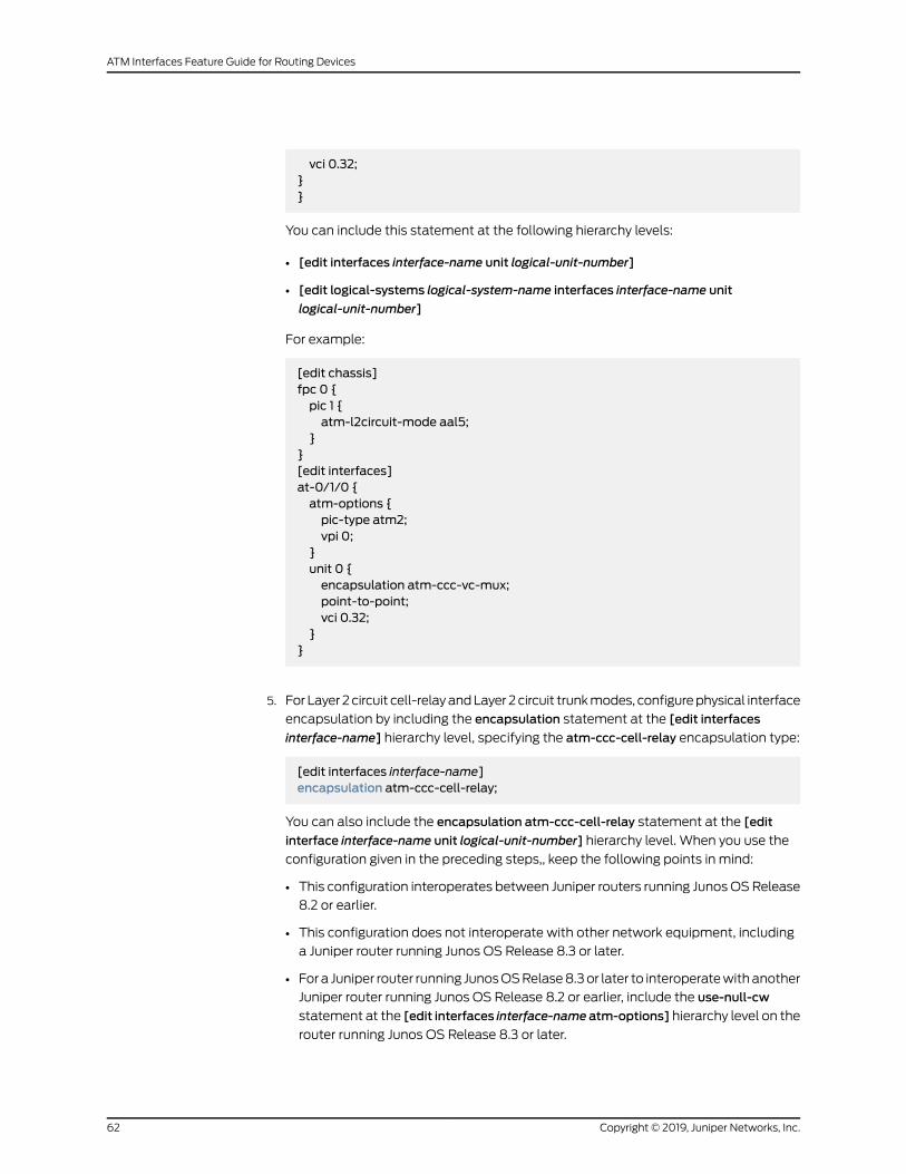
vci 0.32;}}
You can include this statement at the following hierarchy levels:
• [edit interfaces interface-name unit logical-unit-number]
• [edit logical-systems logical-system-name interfaces interface-name unit
logical-unit-number]
For example:
[edit chassis]fpc 0 {pic 1 {atm-l2circuit-mode aal5;
}}[edit interfaces]at-0/1/0 {atm-options {pic-type atm2;vpi 0;
}unit 0 {encapsulation atm-ccc-vc-mux;point-to-point;vci 0.32;
}}
5. For Layer 2circuit cell-relayandLayer 2circuit trunkmodes, configurephysical interface
encapsulation by including the encapsulation statement at the [edit interfaces
interface-name] hierarchy level, specifying the atm-ccc-cell-relay encapsulation type:
[edit interfaces interface-name]encapsulation atm-ccc-cell-relay;
You can also include the encapsulation atm-ccc-cell-relay statement at the [edit
interface interface-name unit logical-unit-number] hierarchy level. When you use the
configuration given in the preceding steps,, keep the following points in mind:
• This configuration interoperates between Juniper routers running JunosOSRelease
8.2 or earlier.
• This configuration does not interoperate with other network equipment, including
a Juniper router running Junos OS Release 8.3 or later.
• Fora Juniper router running JunosOSRelase8.3or later to interoperatewithanother
Juniper router running Junos OS Release 8.2 or earlier, include the use-null-cw
statement at the [edit interfaces interface-nameatm-options] hierarchy level on the
router running Junos OS Release 8.3 or later.
Copyright © 2019, Juniper Networks, Inc.62
ATM Interfaces Feature Guide for Routing Devices

• Theuse-null-cw statement inserts (for sending traffic) or strips (for receiving traffic)
an extra null control word in the MPLS packet.
• The use-null-cw statement is not supported on a router running Junos OS Release
8.2 or earlier.
Formore information about Layer 2 circuits, see the JunosOSVPNs Library for Routing
Devices and the Junos OS Routing Protocols Library.
For example:
[edit chassis]fpc 0 {pic 1 {atm-l2circuit-mode cell;
}}[edit interfaces]at-0/1/0 {encapsulation atm-ccc-cell-relay;atm-options {pic-type atm2;vpi 0;
}unit 0 {encapsulation atm-ccc-cell-relay;point-to-point;vci 0.32;
}}
RelatedDocumentation
ATM2 IQ VC Tunnel CoS Components Overview on page 117•
• Junos OS VPNs Library for Routing Devices
• Junos OS Routing Protocols Library
Layer 2 Circuit Transport Mode on ATMMICs Overview
OnMXSeries routerswith ATMMICs, you can configure Layer 2 circuit cell relay or Layer 2
circuit ATM Adaptation Layer 5 (AAL5). Layer 2 circuit cell relay and Layer 2 circuit AAL5
are defined in EncapsulationMethods for Transport of Asynchronous TransferMode (ATM)
Over MPLS Networks (RFC 4717). Layer 2 circuit cell-relay and Layer 2 circuit AAL5
transport modes allow you to send ATM cells between ATM interfaces across a Layer 2
circuit-enablednetwork. Layer 2circuits aredesigned to transport Layer 2 framesbetween
provider edge (PE) routers across an MPLS backbone.
Layer 2 circuit cell-relay and Layer 2 circuit AAL5 transport modes accept a stream of
ATM cells, convert these to an encapsulated Layer 2 format, and then tunnel them over
an MPLS or IP backbone, where a similarly configured router segments these packets
back into a stream of ATM cells, to be forwarded to the virtual circuit configured for the
far-end router. In Layer 2 circuit cell-relay transportmode,ATMcells arebundled together
63Copyright © 2019, Juniper Networks, Inc.
Chapter 2: Configuring ATM Interfaces

and transported in packet form to the far-end router, where they are segmented back
into individual ATM cells and forwarded to the ATM virtual circuit configured for the
far-end router. You use Layer 2 circuit AAL5 transport mode to send AAL5 segmentation
and reassembly protocol data units (SAR-PDUs) over the Layer 2 circuit.
RelatedDocumentation
Configuring Layer 2 Circuit Transport Mode on ATMMICs on page 64•
• Example: Configuring Layer 2 Circuit Transport Mode on ATMMICs on page 65
Configuring Layer 2 Circuit Transport Mode on ATMMICs
To configure Layer 2 circuit AAL5 or Layer 2 circuit cell relay, perform the following tasks:
• For Layer 2 circuit AAL5mode, configure logical interface encapsulation by including
the encapsulation statement, specifying the atm-ccc-vc-mux encapsulation type:
encapsulation atm-ccc-vc-mux;
You can include this statement at the following hierarchy levels:
• [edit interfaces interface-name unit logical-unit-number]
• [edit logical-systems logical-system-name interfaces interface-name unit
logical-unit-number]
• For Layer 2 circuit cell-relay mode, configure physical interface encapsulation by
including the encapsulation statement at the [edit interfaces interface-name] hierarchy
level, specifying the atm-ccc-cell-relay encapsulation type:
[edit interfaces interface-name]encapsulation atm-ccc-cell-relay;
You can also include the encapsulation atm-ccc-cell-relay statement at the [edit
interface interface-name unit logical-unit-number] hierarchy level.
When you use the configuration given in the preceding steps, keep the following points
in mind:
• Thechassis-level configuration foratm-l2-circuit-mode is not available forATMMICs.
• The absence of the chassis-level configuration for atm-l2-circuit-mode does not
indicate null control word.
For more information about Layer 2 circuits, see the Junos OS VPNs Library for Routing
Devices and the Junos OS Routing Protocols Library.
RelatedDocumentation
Layer 2 Circuit Transport Mode on ATMMICs Overview on page 63•
• Example: Configuring Layer 2 Circuit Transport Mode on ATMMICs on page 65
Copyright © 2019, Juniper Networks, Inc.64
ATM Interfaces Feature Guide for Routing Devices

Example: Configuring Layer 2 Circuit Transport Mode on ATMMICs
This example shows how to configure Layer 2 circuit transport mode on ATMMICs.
• Requirements on page 65
• Overview on page 65
• Configuration on page 65
Requirements
This example uses the following hardware and software components:
• Junos OS Release 12.1 or later for MX Series routers
• A single MX Series router with an ATMMIC with SFP
Overview
This example provides information about configuring the Layer 2 circuit transport mode
on MX Series routers with ATMMICs with SFP. You can configure the Layer 2 circuit
cell-relay or Layer 2 circuit AAL5 transport mode. Layer 2 circuit cell-relay and Layer 2
circuitAAL5 transportmodesallowyou tosendATMcellsbetweenATM interfacesacross
aLayer 2 circuit-enablednetwork. Layer 2 circuits aredesigned to transport Layer 2 frames
betweenprovider edge (PE) routers acrossanMPLSbackbone. In Layer 2 circuit cell-relay
transport mode, ATM cells are bundled together and transported in packet form to the
far-end router, where they are segmented back into individual ATM cells and forwarded
to the ATM virtual circuit configured for the far-end router. You use Layer 2 circuit AAL5
transport mode to send AAL5 segmentation and reassembly protocol data units
(SAR-PDUs) over the Layer 2 circuit.
Configuration
To configure Layer 2 circuit transport mode, perform these tasks:
• Configuring Layer 2 Circuit AAL5 Transport Mode on page 65
• Configuring Layer 2 Circuit Cell-Relay Transport Mode on page 66
Configuring Layer 2 Circuit AAL5 Transport Mode
CLI QuickConfiguration
To quickly configure interface-level Layer 2 circuit AAL5 transport mode, copy and paste
the following commands into the CLI:
[edit]set interface at-0/2/2 atm-options vpi 9set interface at-0/2/2 unit 0 encaps atm-ccc-vc-muxset interface at-0/2/2 unit 0 vci 9.99
The following example requires you to navigate various levels in the configuration
hierarchy. For instructions on how to do that, see Using the CLI Editor in Configuration
Mode in the CLI User Guide.
65Copyright © 2019, Juniper Networks, Inc.
Chapter 2: Configuring ATM Interfaces

Step-by-StepProcedure
To configure Layer 2 circuit AAL5 transport mode on the ATMMIC with SFP, perform the
following tasks:
1. In configurationmode, go to the [edit interfaces]hierarchy level andset the interface
as at-0/2/2.
[edit]user@host# edit interfaces at-0/2/2
2. Set the ATM virtual path identifier (VPI) to 9, by including the vpi 9 statement.
[edit interfaces at-0/2/2]user@host# set vpi 9
3. Configure unit 0 and the physical interface encapsulation.
[edit interfaces at-0/2/2]user@host# edit unit 0[edit interfaces at-0/2/2 unit 0]user@host# set encapsulation atm-ccc-vc-mux
4. Specify the ATM virtual circuit identifier (VCI) as 9.9.
[edit interfaces at-0/2/2 unit 0]user@host#set vci 9.9
Results To view the configuration of AAL5 transport mode:
[edit]user@host# show[edit interfaces]at-0/1/0 {atm-options {vpi 9;
}unit 0 {encapsulation atm-ccc-vc-mux;vci 9.9;
}}
Configuring Layer 2 Circuit Cell-Relay Transport Mode
CLI QuickConfiguration
To quickly configure interface-level Layer 2 circuit cell-relay transport mode, copy and
paste the following commands into the CLI:
[edit]
Copyright © 2019, Juniper Networks, Inc.66
ATM Interfaces Feature Guide for Routing Devices

set interface at-0/2/2 atm-options vpi 10set interface at-0/2/2 unit 0 encaps atm-ccc-cell-relayset interface at-0/2/2 unit 0 vci 10.100
The following example requires you to navigate various levels in the configuration
hierarchy. For instructions on how to do that, see Using the CLI Editor in Configuration
Mode in the CLI User Guide.
Step-by-StepProcedure
To configure Layer 2 circuit cell-relay transport mode on the ATMMIC with SFP, perform
the following tasks:
1. In configurationmode, go to the [edit interfaces]hierarchy level andset the interface
as at-0/2/2.
[edit]user@host# edit interfaces at-0/2/2
2. Set the ATM virtual path identifier (VPI) to 10, by including the vpi 10 statement.
[edit interfaces at-0/2/2]user@host# set vpi 10
3. Configure unit 0 and the physical interface encapsulation.
[edit interfaces at-0/2/2]user@host# edit unit 0[edit interfaces at-0/2/2]user@host# set encapsulation atm-ccc-cell-relay
4. Specify the ATM virtual circuit identifier (VCI) as 10.100.
[edit interfaces at-0/2/2 unit 0]user@host#set vci 10.100
Results To view the configuration of cell-relay transport mode:
[edit]user@host# show[edit interfaces]at-0/1/0 {atm-options {vpi 10;
}unit 0 {encapsulation atm-ccc-cell-relay;vci 10.100;
67Copyright © 2019, Juniper Networks, Inc.
Chapter 2: Configuring ATM Interfaces
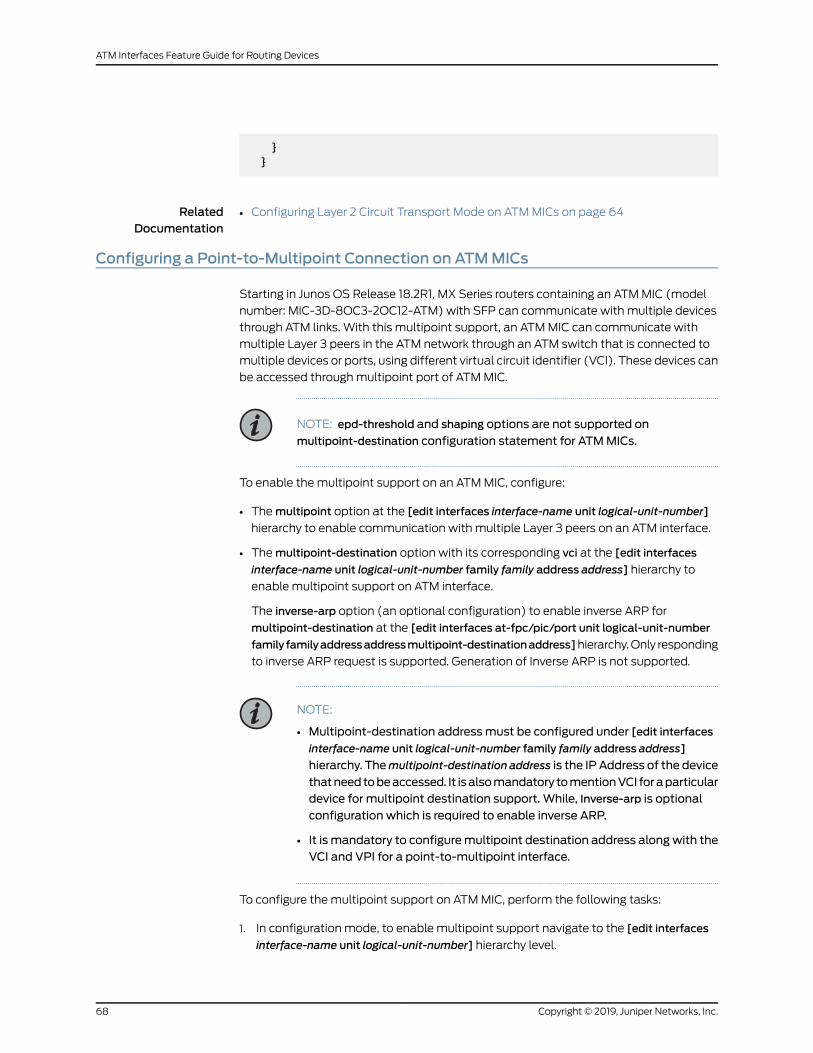
}}
RelatedDocumentation
Configuring Layer 2 Circuit Transport Mode on ATMMICs on page 64•
Configuring a Point-to-Multipoint Connection on ATMMICs
Starting in Junos OS Release 18.2R1, MX Series routers containing an ATMMIC (model
number: MIC-3D-8OC3-2OC12-ATM) with SFP can communicate with multiple devices
through ATM links. With this multipoint support, an ATMMIC can communicate with
multiple Layer 3 peers in the ATM network through an ATM switch that is connected to
multiple devices or ports, using different virtual circuit identifier (VCI). These devices can
be accessed throughmultipoint port of ATMMIC.
NOTE: epd-threshold and shaping options are not supported on
multipoint-destination configuration statement for ATMMICs.
To enable the multipoint support on an ATMMIC, configure:
• Themultipoint option at the [edit interfaces interface-name unit logical-unit-number]
hierarchy to enable communication with multiple Layer 3 peers on an ATM interface.
• Themultipoint-destination option with its corresponding vci at the [edit interfaces
interface-name unit logical-unit-number family family address address] hierarchy to
enable multipoint support on ATM interface.
The inverse-arp option (an optional configuration) to enable inverse ARP for
multipoint-destination at the [edit interfaces at-fpc/pic/port unit logical-unit-number
family familyaddressaddressmultipoint-destinationaddress]hierarchy.Only responding
to inverse ARP request is supported. Generation of Inverse ARP is not supported.
NOTE:
• Multipoint-destination addressmust be configured under [edit interfaces
interface-name unit logical-unit-number family family address address]
hierarchy. Themultipoint-destination address is the IP Address of the device
thatneedtobeaccessed. It isalsomandatory tomentionVCI foraparticulardevice for multipoint destination support. While, Inverse-arp is optional
configuration which is required to enable inverse ARP.
• It is mandatory to configuremultipoint destination address alongwith theVCI and VPI for a point-to-multipoint interface.
To configure the multipoint support on ATMMIC, perform the following tasks:
1. In configuration mode, to enable multipoint support navigate to the [edit interfaces
interface-name unit logical-unit-number] hierarchy level.
Copyright © 2019, Juniper Networks, Inc.68
ATM Interfaces Feature Guide for Routing Devices

[edit ]user@host# edit interfaces interface-name unit logical-unit-number
For example:
[edit ]user@host# edit interfaces at-1/0/0 unit 0
2. By default, all interfaces are assumed to be point-to-point connections. To configure
an interface to be amultipoint connection, include themultipoint statement at the
[edit interfaces interface-name unit logical-unit-number] hierarchy level.
[edit interfaces interface-name unit logical-unit-number]user@host# setmultipoint
For example:
[edit interfaces at-1/0/0 unit 0]user@host# setmultipoint
3. After enabling multipoint, set the source address. To configure the source address,
navigate to the [edit interfaces interface-name unit logical-unit-number family family]
hierarchy level.
[edit interfaces interface-name unit logical-unit-number]user@host# edit family family address address
For example:
[edit interfaces at-1/0/0 unit 0]user@host# edit family inet address 7.0.0.2/24
4. Configure themultipoint-destination address along with the virtual circuit identifier
(VCI) and virtual path identifier (VPI).
NOTE: It is mandatory to configuremultipoint destination address alongwith the VCI and VPI for a point-to-multipoint interface.
[edit interfaces interface-nameunit logical-unit-number family familyaddressaddress]
user@host# setmultipoint-destination address vci vpi-identifier.vci-identifier
For example:
[edit interfaces at-1/0/0 unit 0 family inet address 7.0.0.2/24 ]user@host# setmultipoint-destination 7.0.0.3 vci 100.100
69Copyright © 2019, Juniper Networks, Inc.
Chapter 2: Configuring ATM Interfaces
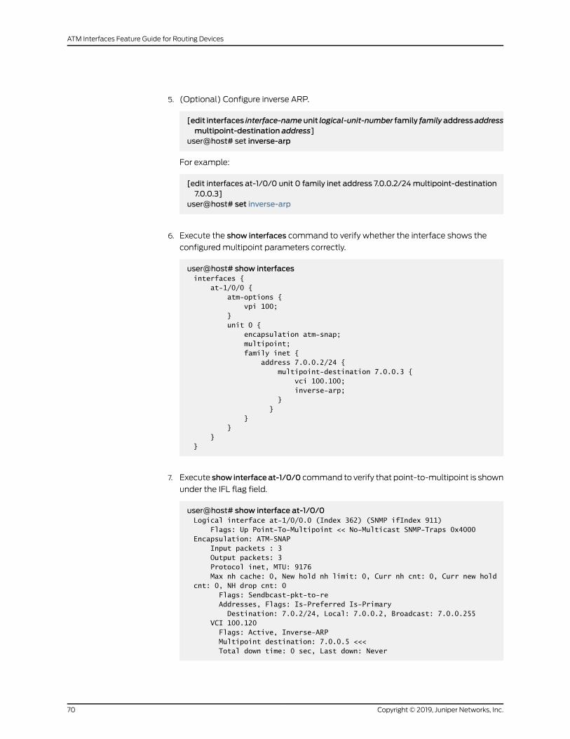
5. (Optional) Configure inverse ARP.
[edit interfaces interface-nameunit logical-unit-number family familyaddressaddressmultipoint-destination address]
user@host# set inverse-arp
For example:
[edit interfaces at-1/0/0 unit 0 family inet address 7.0.0.2/24multipoint-destination7.0.0.3]
user@host# set inverse-arp
6. Execute the show interfaces command to verify whether the interface shows the
configuredmultipoint parameters correctly.
user@host# show interfacesinterfaces { at-1/0/0 { atm-options { vpi 100; } unit 0 { encapsulation atm-snap; multipoint; family inet { address 7.0.0.2/24 { multipoint-destination 7.0.0.3 { vci 100.100; inverse-arp; } } } } } }
7. Execute show interfaceat-1/0/0 command to verify that point-to-multipoint is shown
under the IFL flag field.
user@host# show interface at-1/0/0Logical interface at-1/0/0.0 (Index 362) (SNMP ifIndex 911) Flags: Up Point-To-Multipoint << No-Multicast SNMP-Traps 0x4000 Encapsulation: ATM-SNAP Input packets : 3 Output packets: 3 Protocol inet, MTU: 9176 Max nh cache: 0, New hold nh limit: 0, Curr nh cnt: 0, Curr new hold cnt: 0, NH drop cnt: 0 Flags: Sendbcast-pkt-to-re Addresses, Flags: Is-Preferred Is-Primary Destination: 7.0.2/24, Local: 7.0.0.2, Broadcast: 7.0.0.255 VCI 100.120 Flags: Active, Inverse-ARP Multipoint destination: 7.0.0.5 <<< Total down time: 0 sec, Last down: Never
Copyright © 2019, Juniper Networks, Inc.70
ATM Interfaces Feature Guide for Routing Devices

ARP statistics Received: 0, Sent: 0, Denied: 0, Operation not supported: 0, Bad packet length: 0, Bad protocol: 0, Bad protocol length: 0,
Release History Table DescriptionRelease
Starting in Junos OS Release 18.2R1, MX Series routers containing an ATMMIC(modelnumber:MIC-3D-8OC3-2OC12-ATM)withSFPcancommunicatewith multiple devices through ATM links.
18.2R1
RelatedDocumentation
multipoint•
• family on page 265
• multipoint-destination on page 290
• inverse-arp on page 279
Configuring ATMCell-Relay Pseudowire
In ATM cell-relay mode, one or more ATM cells are bundled together to form a packet
that is sent across the packet-switched network (PSN) using MPLS. In this mode, each
ATMcell and its header are transported over theMPLS cloud. TheATMheader consisting
of the VPI and VCI values is transported across theMPLS cloud or the backhaul network.
By default, all incoming cells are mapped from a single virtual circuit to an ATM
pseudowire. ForATM logical interfaces configuredwithatm-ccc-cell-relayencapsulation,
youcanconfigureATMcell-relaypseudowire inVP-promiscuousmode,port-promiscuous
mode, and VCCmode.
Promiscuous mode allows you to map all incoming cells from either an interface port or
a virtual path (VP) toa single LSPwithout restricting theVCI number. You canmap traffic
from all 65,535 VCIs to a single LSP, or from all 256 VPIs to a single LSP. For
promiscuous-mode configuration guidelines, see “Configuring ATM Cell-Relay
Promiscuous Mode” on page 42.
This topic includes the following tasks:
• Configuring ATM Cell-Relay Pseudowire in Port-Promiscuous Mode on page 71
• Configuring ATM Cell-Relay Pseudowire in VP-Promiscuous Mode on page 72
• Configuring ATM Cell-Relay Pseudowire in VCCMode on page 73
Configuring ATMCell-Relay Pseudowire in Port-PromiscuousMode
To configure ATM cell-relay pseudowire in port-promiscuous mode:
1. In configuration mode, go to the [edit interfaces] hierarchy level and set the interface
as at-0/2/2.
71Copyright © 2019, Juniper Networks, Inc.
Chapter 2: Configuring ATM Interfaces

[edit]user@host#edit interfaces at-0/2/2
2. Tomap incoming traffic, include the promiscuousmode statement at the [edit
interfaces interface-name atm-options] hierarchy level.
[edit interfaces at-0/2/2]user@host#set atm-options promiscuous-mode
3. To configure ATM encapsulation on unit 0, include the encapsulation statement at
the [edit interfaces interface-name] hierarchy level.
[edit interfaces at-0/2/2]user@host#set unit 0 encapsulation atm-ccc-cell-relay
4. Include the allow-any-vci statement at the [edit interfaces interface-name] hierarchy
level.
[edit interfaces at-0/2/2]user@host#set unit 0 allow-any-vci
5. To verify the configuration, you can issue the following operational mode command
in configuration mode:
[edit]user@host#show at-0/2/2
atm-options{promiscuous-mode;}unit 0{encapsulation atm-ccc-cell-relay;allow-any-vci;}
Configuring ATMCell-Relay Pseudowire in VP-PromiscuousMode
To configure ATM cell-relay pseudowire in VP-promiscuous mode:
1. In configuration mode, go to the [edit interfaces] hierarchy level and set the interface
as at-0/2/2.
[edit]user@host#edit interfaces at-0/2/2
Copyright © 2019, Juniper Networks, Inc.72
ATM Interfaces Feature Guide for Routing Devices

2. Tomap incoming traffic to a single LSP and to specify the VPI value as 8, include the
promiscuousmode statement and vpi vpi-identifier statement at the [edit interfaces
interface-name atm-options] hierarchy level.
[edit interfaces at-0/2/2]user@host#set atm-options promiscuous-mode vpi 8
3. To configure ATM encapsulation on unit 0, include the encapsulation statement at
the [edit interfaces interface-name] hierarchy level.
[edit interfaces at-0/2/2]user@host#set unit 0 encapsulation atm-ccc-cell-relay
4. To specify 8 as the VPI value on unit 0, include the vpi vpi-identifier statement at the
[edit interfaces interface-name] hierarchy level.
[edit interfaces at-0/2/2]user@host#set unit 0 vpi 8
5. To verify the configuration, you can issue the following operational mode command
in configuration mode:
[edit]user@host#show at-0/2/2
atm-options{vpi 8;promiscuous-mode;}unit 0{encapsulation atm-ccc-cell-relay;vpi 8;}
Configuring ATMCell-Relay Pseudowire in VCCMode
To configure ATM cell-relay pseudowire in VCCmode:
1. In configuration mode, go to the [edit interfaces] hierarchy level and set the interface
as at-0/2/2.
[edit]user@host#edit interfaces at-0/2/2
2. Tomap incoming traffic to a single LSP and to specify the VPI value as 9, include the
promiscuousmode statement and vpi vpi-identifier statement at the [edit interfaces
interface-name atm-options] hierarchy level.
73Copyright © 2019, Juniper Networks, Inc.
Chapter 2: Configuring ATM Interfaces

[edit interfaces at-0/2/2]user@host#set atm-options promiscuous-mode vpi 9
3. To configure ATM encapsulation on unit 0, include the encapsulation statement at
the [edit interfaces interface-name] hierarchy level.
[edit interfaces at-0/2/2]user@host#set unit 0 encapsulation atm-ccc-cell-relay
4. To specify the VCI value as 9.99 on unit 0, include the vci vci-identifier statement at
the [edit interfaces interface-name] hierarchy level.
[edit interfaces at-0/2/2]user@host#set unit 0 vci 9.99
5. To verify the configuration, you can issue the following operational mode command
in configuration mode:
[edit]user@host#show at-0/2/2
atm-options{vpi 9;promiscuous-mode;}unit 0{encapsulation atm-ccc-cell-relay;vci 9.99;}
RelatedDocumentation
ATM Cell Relay Pseudowire VPI/VCI Swapping Overview•
• Configuring ATM Cell-Relay Pseudowire VPI/VCI Swapping
• allow-any-vci on page 238
• no-vpivci-swapping
• psn-vci (ATM CCC Cell-Relay Promiscuous Mode VPI/VCI Swapping)
• psn-vpi (ATM CCC Cell-Relay Promiscuous Mode VPI/VCI Swapping)
• vci on page 330
• vpi on page 331
Configuring the Layer 2 Circuit Cell-Relay Cell MaximumOverview
Bydefault, each frame contains one cell. For ATM interfaceswith Layer 2 circuit cell-relay
transport mode configured, you can configure the maximum number of ATM cells per
Copyright © 2019, Juniper Networks, Inc.74
ATM Interfaces Feature Guide for Routing Devices
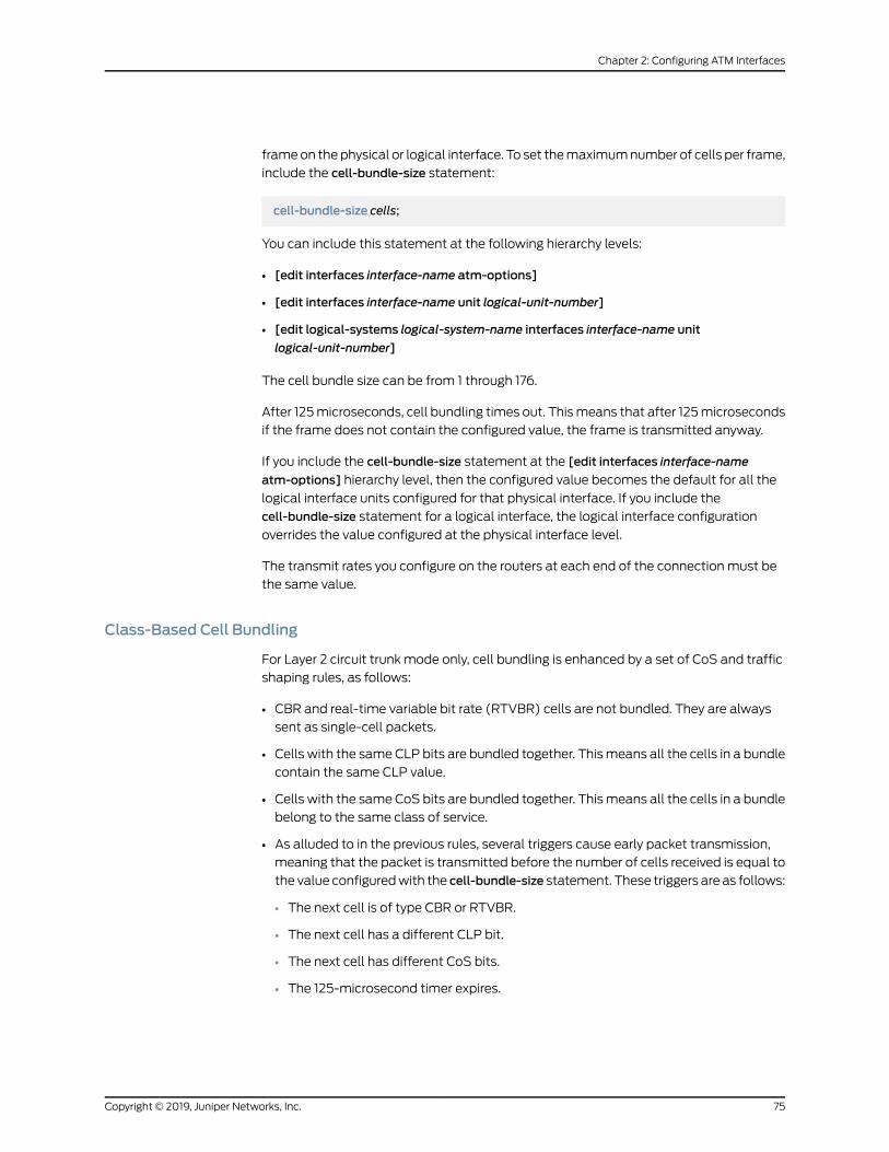
frameon thephysical or logical interface. To set themaximumnumber of cells per frame,
include the cell-bundle-size statement:
cell-bundle-size cells;
You can include this statement at the following hierarchy levels:
• [edit interfaces interface-name atm-options]
• [edit interfaces interface-name unit logical-unit-number]
• [edit logical-systems logical-system-name interfaces interface-name unit
logical-unit-number]
The cell bundle size can be from 1 through 176.
After 125microseconds, cell bundling times out. Thismeans that after 125microseconds
if the frame does not contain the configured value, the frame is transmitted anyway.
If you include the cell-bundle-size statement at the [edit interfaces interface-name
atm-options] hierarchy level, then the configured value becomes the default for all the
logical interface units configured for that physical interface. If you include the
cell-bundle-size statement for a logical interface, the logical interface configuration
overrides the value configured at the physical interface level.
The transmit rates you configure on the routers at each end of the connection must be
the same value.
Class-Based Cell Bundling
For Layer 2 circuit trunk mode only, cell bundling is enhanced by a set of CoS and traffic
shaping rules, as follows:
• CBR and real-time variable bit rate (RTVBR) cells are not bundled. They are always
sent as single-cell packets.
• Cells with the same CLP bits are bundled together. Thismeans all the cells in a bundle
contain the same CLP value.
• Cells with the sameCoS bits are bundled together. Thismeans all the cells in a bundle
belong to the same class of service.
• As alluded to in the previous rules, several triggers cause early packet transmission,
meaning that the packet is transmitted before the number of cells received is equal to
the value configuredwith the cell-bundle-size statement. These triggers are as follows:
• The next cell is of type CBR or RTVBR.
• The next cell has a different CLP bit.
• The next cell has different CoS bits.
• The 125-microsecond timer expires.
75Copyright © 2019, Juniper Networks, Inc.
Chapter 2: Configuring ATM Interfaces

CoS-based cell bundling optimizes the release of a bundle by sending out the cell that
triggers early packet transmission as a single-cell packet. This means that when a cell
triggers early packet transmission, that cell is not bundled. Consequently, certain input
data patterns might cause primarily single-cell packets to be transmitted. For example,
say the output interface receives a steady pattern of two cells froma non-RTVBRqueue,
followed by two cells from a UBR queue. In this case, all transmitted packets contain a
single cell because the first cell triggers a transition and is transmitted by itself. The
second cell is also transmitted by itself because the third cell triggers another transition,
and so on. This effect might not be dramatic with a mix of traffic; it is most evident with
steady traffic patterns, as generatedbyATMtest equipment programmed to emit regular
sequences of CoS queue transitions.
Configuring Layer 2 Circuit TrunkMode Scheduling Overview
For ATM2 IQ interfaces configured to use Layer 2 circuit trunk mode, you can share a
scheduler among32 trunks onanATMport. Aweighted round robin scheduling algorithm
ensures each trunk receives a proportional share of the bandwidth when all trunks are
active, and redistributes bandwidth that would have otherwise been reserved by an
inactive trunk, thus minimizing the latency on each trunk. For general information about
Layer 2 circuit trunk mode, see “Configuring Layer 2 Circuit Transport Mode” on page 54.
For general information about ATM CoS scheduling, see “ATM2 IQ VC Tunnel CoS
Components Overview” on page 117.
Each trunk is associated with a trunk bandwidth. The trunk bandwidth is the maximum
bandwidth used each time a trunk is serviced. We recommend configuring trunk
bandwidths so that the ratio between theminimumandmaximumbandwidths does not
exceed 1:500.
Tominimize latency, the Junos OS does not shape the trunks. As cells are received, they
are immediately transmitted.
To configure trunk bandwidth, include the trunk-bandwidth statement:
trunk-bandwidth rate;
You can include this statement at the following hierarchy levels:
• [edit interfaces interface-name unit logical-unit-number]
• [edit logical-systems logical-system-name interfaces interface-name unit
logical-unit-number]
The trunk bandwidth can be from 1,000,000 through 542,526,792 bps. You can specify
the rate in bits per second or cells per second (cps). You can specify a bits-per-second
value either as a complete decimal number or as a decimal number followed by the
abbreviation k (1000),m (1,000,000), or g (1,000,000,000). You can specify a
cells-per-second value by entering a decimal number followed by the abbreviation c;
values expressed in cells per second are converted to bits per second bymeans of the
formula 1 cps = 384 bps.
Copyright © 2019, Juniper Networks, Inc.76
ATM Interfaces Feature Guide for Routing Devices

The Junos OS rounds off the configured value. Therefore, we recommend that you
configure aminimum trunk bandwidth of 1m. From 1m, configure values in increments of
500k.
RelatedDocumentation
Configuring Layer 2 Circuit Transport Mode on page 54•
• ATM2 IQ VC Tunnel CoS Components Overview on page 117
Configuring CoSQueues in Layer 2 Circuit TrunkMode
OnATM2 IQ interfaces, you can configure ATMCoS scheduling for AAL5mode and Layer
2 circuit trunk mode. For general information about ATM CoS, see “ATM2 IQ VC Tunnel
CoS Components Overview” on page 117.
When you configure CoS scheduling in Layer 2 circuit trunkmode, the trunk is defined on
the logical interface, and four CoS queues are opened in the trunk. For each CoS queue,
you specify a priority and a transmit weight. CoS queues are serviced using a weighted
round robin (WRR) algorithm. One queue is serviced with strictly high priority and the
remaining queues are serviced with theWRR.
For Layer 2 circuit trunk mode, only strict mode is supported. Alternate mode is not
supported.
To configure CoS queues in Layer 2 circuit trunk mode, perform the following tasks:
1. Include the encapsulation atm-ccc-cell-relay statement at the [edit interfaces
at-fpc/pic/port] hierarchy level:
[edit interfaces at-fpc/pic/port]encapsulation (atm-ccc-cell-relay | ether-vpls-over-atm-llc);
2. Include the scheduler-maps statement at the [edit interfaces at-fpc/pic/port
atm-options] hierarchy level:
[edit interfaces at-fpc/pic/port atm-options]scheduler-mapsmap-name {forwarding-class (class-name | assured-forwarding | best-effort |expedited-forwarding | network-control);
vc-cos-mode strict;}
3. Include theatm-scheduler-map, trunk-bandwidth, and trunk-id statementsat the [edit
interfaces at-fpc/pic/port unit logical-unit-number] hierarchy level:
[edit interfaces at-fpc/pic/port unit logical-unit-number]atm-scheduler-map (map-name | default);trunk-bandwidth rate;trunk-id number;
77Copyright © 2019, Juniper Networks, Inc.
Chapter 2: Configuring ATM Interfaces

For information aboutATMschedulermaps, see “Configuring anATMSchedulerMap”
on page 119.
For information about trunk identification numbers, see “Configuring Layer 2 Circuit
TransportMode”onpage54. For informationabout trunkbandwidths, see “Configuring
Layer 2 Circuit Trunk Mode Scheduling Overview” on page 76.
Strict mode CoS queue priority works as follows:
• Scheduling—One queue has strictly high priority and is always serviced before the
remaining queues are serviced by a weighted round robin. This means the packets
in a high priority queue are sent first until the queue is empty. Then low priority
queues send packets until their weight quota becomes zero or negative.
• Latency—Each trunk is associated with a trunk bandwidth. The trunk bandwidth is
the maximum bandwidth used each time a trunk is serviced. In the scheduling
process, each trunk is serviced in aWRR. Themaximum latency for any trunk to
begin transmitting is equal to thesumof theweightsofall previouslyqueued trunks.
Trunks without data do not affect output scheduling. As long as all the trunks have
data, the exactweight proportions aremaintained. If a trunk runs out of data during
its turn, it is no longer included in theWRR.When the trunkgetsmoredata, the trunk
is placed at the end of the queue. For more information, see “Configuring Layer 2
Circuit Trunk Mode Scheduling Overview” on page 76.
Within a single trunk, themaximum latency of a high priority queue is the time it takes
to transmit one ATM cell. The latency of a low priority queue is the sumof high priority
queue burst time and the transmission time of the remaining low priority queues’
weight.
• Bandwidthdistribution—Trunksareserviced inaWRRbasedon the trunkbandwidth.
Within a single trunk, the high priority queue consumes the bandwidth first regardless
of its weight. The remaining bandwidth is distributed to the low priority queues in
proportion to their weights.
Consider the following example:
• You configure a trunk with weights of 10 percent, 20 percent, 30 percent, and
40 percent for queues 0, 1, 2, and 3, respectively.
• You configure queue 0 to be a high priority queue.
• Queue 0 does not have cells to transmit.
In this scenario, queues 1, 2 and 3 receive 2/9, 3/9, and 4/9 of the bandwidth,
respectively.
NOTE: Constantbit rate (CBR) trafficalwaysenters thestrictlyhighpriority
queue.
For more information about strict and alternatemodes, see “ATM2 IQ VC Tunnel CoS
Components Overview” on page 117.
Copyright © 2019, Juniper Networks, Inc.78
ATM Interfaces Feature Guide for Routing Devices

For general information about Layer 2 circuit trunk mode, see “Configuring Layer 2
Circuit Transport Mode” on page 54.
For interfaces configured in trunk mode, you can also configure dual EPD thresholds
depending on packet loss priorities (PLPs). For more information, see “Configuring
Two EPD Thresholds per Queue” on page 133.
RelatedDocumentation
Configuring Layer 2 Circuit Transport Mode on page 54•
• Configuring an ATM Scheduler Map on page 119
• Configuring Layer 2 Circuit Trunk Mode Scheduling Overview on page 76
• Configuring Two EPD Thresholds per Queue on page 133
Configuring the Timeout for Bundling of Layer 2 Circuit Cell-Relay Cells
Layer 2 cell-relay encapsulation supports the concatenation (aggregation) of multiple
ATMcells in a single encapsulatedpacket that is transmittedonapseudowire. Bydefault,
each packet contains one cell. For ATM interfaceswith Layer 2 circuit cell-relay transport
mode configured, you can configure the time threshold (inmicroseconds) that the router
uses to concatenateATMcells and transmit the cells in a single frameon thepseudowire.
To set the period for which the ATM cells must be collected to be bundled in a single
frame being transmitted on the pseudowire, include the cell-bundle-timeout statement
at the [edit interfaces interface-name atm-options] or the [edit interfaces interface-name
unit logical-unit-number] hierarchy level.
Based on this configuration, the router attempts to collect and concatenate ATM cells
in a single ATM cell relay-encapsulated packet and transmit the packet on a pseudowire
connection.When the routerdetects that theallotted time interval hasexpired, the router
forwards the packet even if it contains fewer than the specified maximum number of
aggregatedcells per packet. Thecell concatenationor bundling functionality is controlled
by the timeout value and themaximum number of cells to be concatenated.
To configure the period for which the ATM cells are aggregated and bundled before they
are transmitted in a single frame on a pseudowire connection:
• Specify the number of microseconds for which the ATM cells must be bundled before
the timer expires and the cells are transmitted in a single frame.
[edit interfaces interface-name atm-options]user@host# set cell-bundle-timeoutmicroseconds
When the router detects that the allotted time interval has expired, the router forwards
the MPLS packet even if it contains fewer than the specified maximum number of
aggregated cells per packet.
RelatedDocumentation
Configuring the Layer 2 Circuit Cell-Relay Cell MaximumOverview on page 74•
• cell-bundle-timeout
79Copyright © 2019, Juniper Networks, Inc.
Chapter 2: Configuring ATM Interfaces

Configuring an ATM1 Cell-Relay Circuit Overview
For ATM1 interfaces, you can create an ATM cell-relay circuit by configuring an entire
ATM physical device or an individual VC. When you configure an entire device, only
cell-relay encapsulation is allowed on the logical interfaces; for ATM1 PICs, you use the
atm-options statement to control the number and location of VCs. The configuration of
allowed VCs on both ingress and egress ATM interfaces should be the same. For most
interfaces, you candefine amaximumof 4090VCsper interface. The highest-numbered
VC value you can configure is 4089. Promiscuous mode removes these limits. For more
information, see “Configuring ATM Cell-Relay Promiscuous Mode” on page 42.
For ATM1 interfaces, if you are dedicating the entire device to a cell-relay circuit, include
the allow-any-vci statement in the configuration of unit 0:
allow-any-vci;
You can include this statement at the following hierarchy levels:
• [edit interfaces interface-name unit 0]
• [edit logical-systems logical-system-name interfaces interface-name unit 0]
Once you include this statement, you cannot configure other logical interfaces in the
same physical interface.
NOTE: When you use ATMCCC cell-relay encapsulation, youmust configurethe logical encapsulation as atm-ccc-cell-relay. You cannot mix different
logical encapsulation types on an interface that you have configured withATM CCC cell-relay physical encapsulation.
• Example: Configuring an ATM1 Cell-Relay Circuit on page 80
Example: Configuring an ATM1 Cell-Relay Circuit
To configure an ATM1 cell-relay circuit:
[edit interfaces at-1/2/0]encapsulation atm-ccc-cell-relay;atm-options {pic-type atm1;vpi 0maximum-vcs 256;
}unit 0 {point-to-point;encapsulation atm-ccc-cell-relay;allow-any-vci;
}
Copyright © 2019, Juniper Networks, Inc.80
ATM Interfaces Feature Guide for Routing Devices

Configuring an Individual VC on a Logical Interface
To configure an individual VC on a logical interface:
[edit interfaces at-1/1/0]encapsulation atm-ccc-cell-relay;atm-options {pic-type atm1;vpi 0maximum-vcs 256;
}unit 120 {encapsulation atm-ccc-cell-relay;vci 0.120;
}
Configuring Non-promiscuous port mode
To configure non-promiscuous port mode:
[edit interfaces at-0/0/1]encapsulation atm-ccc-cell-relay;atm-options {pic-type atm1;vpi 0 {maximum-vcs 100;
}vpi 1 {maximum-vcs 300;
}vpi 4 {maximum-vcs 200;
}}unit 0 {encapsulation atm-ccc-cell-relay;allow-any-vci;
}
Configuring Nonpromiscuous VPI Mode
To configure non-promiscuous VPI mode:
[edit interfaces at-0/0/1]encapsulation atm-ccc-cell-relay;atm-options {pic-type atm1;vpi 0 {maximum-vcs 100;
}}unit 0 {encapsulation atm-ccc-cell-relay;vpi 0;
81Copyright © 2019, Juniper Networks, Inc.
Chapter 2: Configuring ATM Interfaces

}
Configuring Nonpromiscuous VCI Mode
To configure non-promiscuous VCI mode:
[edit interfaces at-0/0/1]encapsulation atm-ccc-cell-relay;atm-options {pic-type atm1;vpi 0 {maximum-vcs 100;
}}unit 0 {encapsulation atm-ccc-cell-relay;vci 0.50
}
RelatedDocumentation
allow-any-vci on page 238•
• atm-options on page 241
• atm-encapsulation on page 240
• encapsulation (Logical Interface) on page 251
• encapsulation on page 255
• unit on page 319
Configuring PPP over ATM2 Encapsulation Overview
For ATM2 IQ interfaces, you can configure PPP over AAL5 encapsulation, as described
in RFC 2364, PPP over AAL5. PPP over ATM encapsulation associates a PPP link with an
ATM AAL5 PVC.
The Junos OS supports three PPP over ATM encapsulation types:
• atm-ppp-llc—PPP over AAL5 LLC.
• atm-ppp-vc-mux—PPP over ATM AAL5multiplex.
• atm-mlppp-llc—Multilink PPP over ATM AAL5 LLC. For this encapsulation type, your
router must be equipped with a Link Services or Voice Services PIC. MLPPP over ATM
encapsulation is not supported on ATM2 IQ OC48 interfaces.
To enable PPP over ATMencapsulation, include the encapsulation statement, specifying
the atm-mlppp-llc, atm-ppp-llc, or atm-ppp-vc-mux encapsulation type:
encapsulation (atm-mlppp-llc | atm-ppp-llc | atm-ppp-vc-mux);
You can include this statement at the following hierarchy levels:
Copyright © 2019, Juniper Networks, Inc.82
ATM Interfaces Feature Guide for Routing Devices

• [edit interfaces interface-name unit logical-unit-number]
• [edit logical-systems logical-system-name interfaces interface-name unit
logical-unit-number]
When you configure PPP over ATM encapsulation, you can enable PPP Challenge
Handshake Authentication Protocol (CHAP) and keepalives on the logical interface. For
more information about PPP CHAP and keepalives, see Configuring the PPP Challenge
Handshake Authentication Protocol and Configuring Keepalives.
NOTE: When you usePPPover ATMencapsulation,we recommend that younot include the oam-period statement in the configuration. Instead, we
recommend that you enable keepalives to detect connection failures.
Example: Configuring PPP over ATM2 IQ Encapsulation
To configure three logical interfaces with PPP over ATM encapsulation:
[edit interfaces]at-0/1/0 {atm-options {pic-type atm2;vpi 0;vpi 2;
}unit 0 {encapsulation atm-ppp-llc;ppp-options {chap {access-profile pe-B-ppp-clients;local-name "pe-A-at-0/1/0";
}}keepalives interval 5 up-count 6 down-count 4;vci 0.120;family inet address 192.168.13.13/30;
}unit 1 {encapsulation atm-ppp-vc-mux;vci 2.120;keepalives interval 6 up-count 6 down-count 4;family inet address 192.168.14.13/30;
}unit 2 {encapsulation atm-ppp-vc-mux;ppp-options {chap {passive;access-profile pe-A-ppp-clients;local-name "pe-A-at-0/1/0";
}}
83Copyright © 2019, Juniper Networks, Inc.
Chapter 2: Configuring ATM Interfaces

keepalives interval 5 up-count 6 down-count 4;vci 2.121;family inet address 192.168.15.13/30;
}}
ConfiguringMultilink PPP over ATM2 IQ Encapsulation
To configure multilink PPP over ATM2 IQ encapsulation:
[edit interfaces]at-0/0/0 {atm-options {pic-type atm2;vpi 10;
}unit 0 {encapsulation atm-mlppp-llc;ppp-options {chap {access-profile pe-B-ppp-clients;local-name “ pe-A-at-0/0/0”;
}}keepalive interval 5 up-count 6 down-count 4;vci 10.120;family mlppp {bundle ls-0/3/0.0;
}}
}at-0/0/1 {atm-options {pic-type atm2;vpi 11;
}unit 1 {encapsulation atm-mlppp-llc;ppp-options {chap {access-profile pe-B-ppp-clients;local-name “ pe-A-at-0/0/0”;
}}keepalive interval 5 up-count 6 down-count 4;vci 11.120;family mlppp {bundle ls-0/3/0.0;
}}
}at-1/2/3 {atm-options {pic-type atm2;
Copyright © 2019, Juniper Networks, Inc.84
ATM Interfaces Feature Guide for Routing Devices
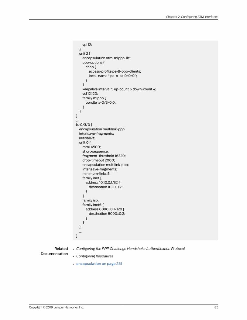
vpi 12;}unit 2 {encapsulation atm-mlppp-llc;ppp-options {chap {access-profile pe-B-ppp-clients;local-name “ pe-A-at-0/0/0”;
}}keepalive interval 5 up-count 6 down-count 4;vci 12.120;family mlppp {bundle ls-0/3/0.0;
}}
}...ls-0/3/0 {encapsulationmultilink-ppp;interleave-fragments;keepalive;unit 0 {mrru 4500;short-sequence;fragment-threshold 16320;drop-timeout 2000;encapsulationmultilink-ppp;interleave-fragments;minimum-links 8;family inet {address 10.10.0.1/32 {destination 10.10.0.2;
}}family iso;family inet6 {address 8090::0:1/128 {destination 8090::0:2;
}}
}...
}
RelatedDocumentation
Configuring the PPP Challenge Handshake Authentication Protocol•
• Configuring Keepalives
• encapsulation on page 251
85Copyright © 2019, Juniper Networks, Inc.
Chapter 2: Configuring ATM Interfaces

Configuring aMulticast-Capable ATM1 or ATM2 IQ Connection
For ATM1 and ATM2 IQ interfaces, you can configure a multicast-capable connection.
Bydefault, ATMconnectionsassumeunicast traffic. If yourATMswitchperformsmulticast
replication, you can configure the connection to support multicast traffic by including
themulticast-vci statement:
multicast-vci vpi-identifier.vci-identifier;
You can include this statement at the following hierarchy levels:
• [edit interfaces interface-name unit logical-unit-number]
• [edit logical-systems logical-system-name interfaces interface-name unit
logical-unit-number]
vci-identifier and vpi-identifier are the VCI and VPI identifiers, which define the ATM VCI
over which the switch is expecting to receive multicast packets for replication.
You can configure multicast support only on point-to-multipoint ATM connections.
Configuring the ATMOAM F5 Loopback Cell Threshold
For ATM1 and ATM2 IQ interfaces with an ATM encapsulation, you can configure the
OAM F5 loopback cell threshold on VCs. This is the minimum number of consecutive
OAM F5 loopback cells received before a VC is declared up, or the minimum number of
consecutive OAM F5 loopback cells lost before a VC is declared down.
Bydefault,when fiveconsecutiveOAMF5 loopbackcellsare received, theVC is considered
to be up, and when five consecutive cells are lost, the VC is considered to be down. To
modify these values, include the oam-liveness statement:
oam-liveness {up-count cells;down-count cells;
}
For a list of hierarchy levels at which you can include this statement, see oam-liveness.
The cell count can be a value from 1 through 255.
Configuring the OAM F4 Cell Flows
For ATM2 IQ interfaces, the F4 flow cell is used for management of the VP level. If your
router is equipped with an ATM2 IQ PIC, you can configure OAM F4 cell flows to identify
and report VPC defects and failures. The Junos OS supports three types of OAM F4 cells
in end-to-end F4 flows:
• Virtual Path Alarm Indication Signal (VP-AIS)
• Virtual Path Remote Defect Indication (VP-RDI)
Copyright © 2019, Juniper Networks, Inc.86
ATM Interfaces Feature Guide for Routing Devices

• Virtual Path Loopback
The Junos OS does not support segment F4 flows, VPC continuity check, or VP
performancemanagement functions.
On each VP, you can configure an interval during which to transmit loopback cells by
including the oam-period statement at the [edit interfaces interface-name atm-options
vpi vpi-identifier] hierarchy level:
[edit interfaces interface-name atm-options vpi vpi-identifier]oam-period (disable | seconds);
When you add a VPI at the atm-options hierarchy, an end-to-end F4 VCI is automatically
opened to send and receive OAM F4, VP-AIS, and VP-RDI cells. If you enable OAM by
including the oam-period statement in the configuration, the router sends and receives
OAM F4 loopback cells.
If the physical ATM interface is configured with encapsulation type atm-ccc-cell-relay,
then F4 VCIs are not created, and F4 OAM processing is not performed for the VPIs
configured on that interface.
Tomodify OAM liveness values on a VP, include the oam-liveness statement at the [edit
interfaces interface-name atm-options vpi vpi-identifier] hierarchy level:
[edit interfaces interface-name atm-options vpi vpi-identifier]oam-liveness {up-count cells;down-count cells;
}
up-count is the minimum number of consecutive OAM F4 loopback cells received on a
VPI before it is declared up.
down-count is the minimum number of consecutive OAM F4 loopback cells lost before
a VPI is declared down.
When a VP-AIS or VP-RDI cell is received, the VPI is marked down. When a VP-AIS cell
is received on a VPI, a VP-RDI is generated and transmitted on the same VPI. When an
OAM F4 loopback request cell is received, the router sends a loopback reply cell, even if
the oam-period statement is not included in the configuration of the VPI.
WhenaVPI ismarkeddownbecause theVPI receivesVP-AIS, VP-RDI, VC-AIS, or VC-RDI
cells, or because the VPI does not receive down-count consecutive OAM F4 loopback
replies, all the VCIs that belong to the VPI are marked down. When a VPI is marked up,
all the VCIs that belong to the VPI are marked up. The status of logical interfaces is also
changed when the status of the last VCI on that interface is changed.
For a configuration example, see “Example: Configuring ATM2 IQ Interfaces” on page 38.
87Copyright © 2019, Juniper Networks, Inc.
Chapter 2: Configuring ATM Interfaces
NOTE: For interfaces that are configured for cell-relay promiscuous virtualpath identifier (VPI) mode, the show interfaces command output does not
show (OAM) F4 cell statistics.
Defining the ATMOAM F5 Loopback Cell Period
For ATM1 andATM2 IQ interfaceswith anATMencapsulation, you can configure theOAM
F5 loopback cell period on virtual circuits. This is the interval at which OAM F5 loopback
cells are transmitted.
By default, no OAM F5 loopback cells are sent. To send OAM F5 loopback cells, include
the oam-period statement:
oam-period (disable | seconds);
For a list of hierarchy levels at which you can include this statement, see oam-period.
The period can be from 1 through 900 seconds. You can also choose the disable option
to disable the OAM loopback cell transmit feature.
OAM VC-AIS and VC-RDI defect indication cells are used for identifying and reporting
VC defects end-to-end. When a physical link or interface failure occurs, intermediate
nodes insert OAM AIS cells into all the downstream VCs affected by the failure. Upon
receiving an AIS cell on a VC, the router marks the logical interface down and sends an
RDI cell on the same VC to notify the remote end of the error status. When an RDI cell is
received on a VC, the router sets the logical interface status to down. When no AIS or
RDI cells are received for 3 seconds, the router sets the logical interface status to up. You
do not need to configure anything to enable defect indication.
Copyright © 2019, Juniper Networks, Inc.88
ATM Interfaces Feature Guide for Routing Devices

Configuring Fixed Classification on an ATM IMA Pseudowire
You configure fixed classification on the ATM IMA pseudowire logical interface (unit) by
specifying a forwarding class, which is applied to all packets received by the logical
interface. To complete this configuration, you can define a forwarding class at the [edit
class-of-service forwarding-classes] hierarchy level. If you do not define a forwarding
class, the default class is used.
The following steps require you to navigate various levels in the configuration hierarchy.
For information about navigating the CLI, see Using the CLI Editor in Configuration Mode
in the CLI User Guide.
NOTE: CoS fixed classification on an ATM IMA pseudowire is not applicableon ACX5048 and ACX5096 routers.
To configure CoS fixed classification on an ATM IMA pseudowire:
1. Define the ATM IMA pseudowire. For information about defining the ATM IMA
pseudowire, see “Configuring Inverse Multiplexing for ATM (IMA) on ACX Series” on
page 28.
2. In configuration mode, go to the [edit class-of-service] hierarchy level:
[edit]user@host# edit class-of-service
3. Define the forwarding class to apply to the input logical interface, if the default
forwarding class is not used:
[edit class-of-service]user@host# set forwarding-classes class class-name queue-num queue-num
4. Specify the ATM IMA interface on which to include the forwarding class:
[edit class-of-service]user@host# edit interfaces at-fpc/pic/port
5. Configure the logical unit:
[edit class-of-service interfaces at-fpc/pic/port]user@host# edit unit logical-unit-number
6. Apply the forwarding class to the logical interface:
[edit class-of-service interfaces at-fpc/pic/port unit logical-unit-number]
89Copyright © 2019, Juniper Networks, Inc.
Chapter 2: Configuring ATM Interfaces
user@host# set forwarding-class class-name
After youhaveconfigured fixedclassification, enter the commitcommand inconfiguration
mode.
RelatedDocumentation
Understanding CoS on ATM IMA Pseudowire Interfaces Overview on page 16•
• Example: Configuring Fixed Classification on an ATM IMA Pseudowire on page 90
• Configuring Policing on an ATM IMA Pseudowire on page 99
• Configuring Shaping on an ATM IMA Pseudowire on page 93
Example: Configuring Fixed Classification on an ATM IMA Pseudowire
This example shows the configuration of fixed classification on an ATM IMA pseudowire.
Fixedclassification is configuredon the logical interface (unit) of theATM IMApseudowire.
The software assigns the fixed classification to packets on the basis of the fixed
classification parameters associated with the logical interface on which the ATM cells
are received.
NOTE: This example is not applicable on ACX5048 and ACX5096 routers.
• Requirements on page 90
• Overview on page 90
• Configuration on page 91
Requirements
This example uses the following hardware and software components:
• ACX Series router
• Junos OS Release 12.2 or later
• A previously configured ATM IMA pseudowire. For steps to configure an ATM IMA
pseudowire, see “Configuring Inverse Multiplexing for ATM (IMA) on ACX Series” on
page 28.
Overview
In this example, the configured forwarding class fc-1 is applied to all packets received on
the ingress logical interface at-0/0/16 unit 0. The fixed classification classifies all traffic
on the logical interface unit zero (0) to queue-num 1.
Copyright © 2019, Juniper Networks, Inc.90
ATM Interfaces Feature Guide for Routing Devices

Configuration
The following example requires you to navigate various levels in the configuration
hierarchy. For informationaboutnavigating theCLI, seeUsing theCLI Editor inConfiguration
Mode in the CLI User Guide.
To configure fixed classification on an ATM IMA Pseudowire, perform these tasks:
• Configuring a Forwarding Class on page 91
• Applying the Forwarding Class on page 91
• Results on page 92
CLI QuickConfiguration
To quickly configure this example, copy the following commands, paste them in a text
file, remove any line breaks, change any details necessary to match your network
configuration, and then copyandpaste the commands into theCLI at the [edit] hierarchy
level:
set class-of-service forwarding-classes class fc-1 queue-num 1set class-of-service interfaces at-0/0/16 unit 0 forwarding-class fc-1
Configuring a Forwarding Class
Step-by-StepProcedure
To define a forwarding class, which is applied to the ingress logical interface:
In configuration mode, go to the following hierarchy level:1.
[edit]user@host# edit class-of-service forwarding-classes
2. Define the forwarding class to apply to the input logical interface:
[edit class-of-service forwarding-classes]user@host# set class fc-1 queue-num 1
Applying the Forwarding Class
Step-by-StepProcedure
To apply the forwarding class to the logical ATM IMA pseudowire:
Specify the ATM IMA interface on which to include the forwarding class:1.
[edit class-of-service]user@host# edit interfaces at-0/0/16
2. Configure the logical interface:
[edit class-of-service interfaces at-0/0/16 ]user@host# edit unit 0
91Copyright © 2019, Juniper Networks, Inc.
Chapter 2: Configuring ATM Interfaces
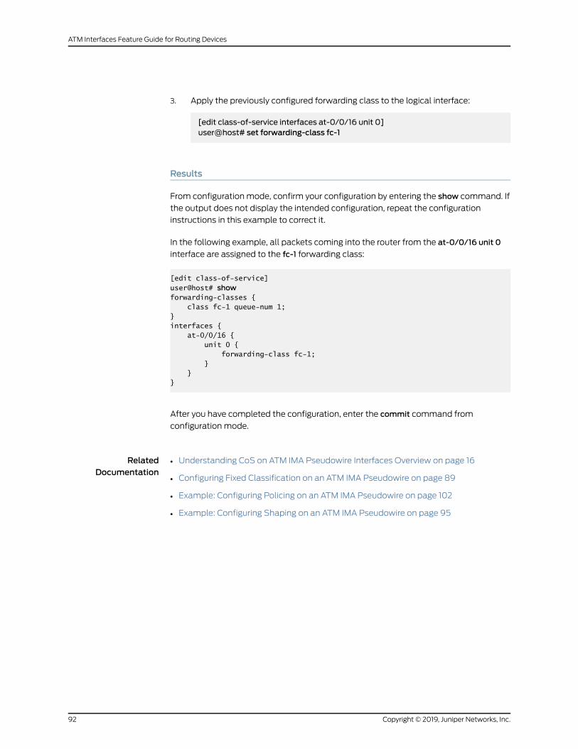
3. Apply the previously configured forwarding class to the logical interface:
[edit class-of-service interfaces at-0/0/16 unit 0]user@host# set forwarding-class fc-1
Results
From configuration mode, confirm your configuration by entering the show command. If
the output does not display the intended configuration, repeat the configuration
instructions in this example to correct it.
In the following example, all packets coming into the router from the at-0/0/16 unit 0
interface are assigned to the fc-1 forwarding class:
[edit class-of-service]user@host# showforwarding-classes { class fc-1 queue-num 1;}interfaces { at-0/0/16 { unit 0 { forwarding-class fc-1; } }}
After you have completed the configuration, enter the commit command from
configuration mode.
RelatedDocumentation
Understanding CoS on ATM IMA Pseudowire Interfaces Overview on page 16•
• Configuring Fixed Classification on an ATM IMA Pseudowire on page 89
• Example: Configuring Policing on an ATM IMA Pseudowire on page 102
• Example: Configuring Shaping on an ATM IMA Pseudowire on page 95
Copyright © 2019, Juniper Networks, Inc.92
ATM Interfaces Feature Guide for Routing Devices

Configuring Shaping on an ATM IMA Pseudowire
OnACXSeries routers, ATMshaping is applied in theegressdirectiononly.Only cell-based
shaping is supported. A traffic control profile, which defines the ATM scheduling
parameters, is configured at the [edit class-of-service] hierarchy level. The traffic control
profile is thenapplied to theATMlogical interfaceconfiguredat the [editclass-of-service]
hierarchy level.
NOTE: TheconfigurationofATMshaping requires the inclusionof theper-unit
scheduler statement at the [edit interfaces interface-name] hierarchy level.
NOTE: Configuring shaping on an ATM IMA pseudowire is not applicable onACX5048 and ACX5096 routers.
The following steps require you to navigate various levels in the configuration hierarchy.
For information about navigating the CLI, see Using the CLI Editor in Configuration Mode
in the CLI User Guide.
To configure a traffic-shaping profile on an ATM IMA pseudowire:
1. Define the ATM IMA pseudowire. For information about defining the ATM IMA
pseudowire, see “Configuring Inverse Multiplexing for ATM (IMA) on ACX Series” on
page 28.
2. In configuration mode, go to the [edit class-of-service] hierarchy level:
[edit]user@host# edit class-of-service
3. Specify the traffic-shaping profile:
[edit class-of-service]user@host# edit traffic-control-profiles profile-name
The following steps describe the traffic control profile options that you can configure.
The options include atm-service, delay-buffer-rate,max-burst-size, peak-rate, and
sustained-rate.
4. (Optional)Specify the service category thatdetermines the traffic-shapingparameter
for the ATM queue at the ATM IMA pseudowire:
[edit class-of-service traffic-control-profiles profile-name]user@host# set atm-service (cbr | nrt-vbr | rt-vbr)
93Copyright © 2019, Juniper Networks, Inc.
Chapter 2: Configuring ATM Interfaces

Select one of the following service traffic categories, depending on the needs of your
network: constant bit rate (cbr), non-real-time variable bit rate (nrtvbr), or real-time
variable bit rate (rtvbr). All service traffic categories must include the peak-rate and
cdvt statements for the configuration to work. The peak-rate statement limits the
maximum traffic allowed and the cdvt statement ensures that the configuration
functions correctly.
5. (Optional) Specify the delay-buffer calculation:
[edit class-of-service traffic-control-profiles profile-name]user@host# set delay-buffer-rate cps
The delay-buffer calculation can be specified as cells per second—1000 cells per
second (cps) through 160,000,000,000 cps.
6. (Optional) Define the maximum number of cells that a burst of traffic can contain,
from 1 through 4000 cells:
[edit class-of-service traffic-control-profiles profile-name]user@host# setmax-burst-sizemax-burst-size
7. Define the largest number of cells per second that the shaper processes before it
drops packets, from 61 cps through 38,641 cps:
[edit class-of-service traffic-control-profiles profile-name]user@host# set peak-rate peak-rate
Themaximumpeak rate value depends on the number of links in the IMAbundle—the
more the number of links, the higher the possible peak rate.
8. (Optional) Define the normal traffic rate averaged over time, from 61 cps through
38,641 cps:
[edit class-of-service traffic-control-profiles profile-name]user@host# set sustained-rate cps
9. To complete the configuration, configure the per-unit scheduler:
[edit interfaces interface-name]user@host# set per-unit scheduler
After you have configured shaping on theATM IMA interface, enter the commit command
from configuration mode.
RelatedDocumentation
Understanding CoS on ATM IMA Pseudowire Interfaces Overview on page 16•
• Example: Configuring Shaping on an ATM IMA Pseudowire on page 95
Copyright © 2019, Juniper Networks, Inc.94
ATM Interfaces Feature Guide for Routing Devices
• Configuring Fixed Classification on an ATM IMA Pseudowire on page 89
• Configuring Policing on an ATM IMA Pseudowire on page 99
Example: Configuring Shaping on an ATM IMA Pseudowire
The following example shows the configuration of shaping on an ATM IMA pseudowire.
On ACX Series routers, the ATM shaper is applied on the egress logical (unit) interface.
NOTE: This example is not applicable on ACX5048 and ACX5096 routers.
• Requirements on page 95
• Overview on page 95
• Configuration on page 96
Requirements
This example uses the following hardware and software components:
• ACX Series router
• Junos OS Release 12.2 or later
• A previously configured ATM IMA pseudowire. For steps to configure an ATM IMA
pseudowire, see “Configuring Inverse Multiplexing for ATM (IMA) on ACX Series” on
page 28.
Overview
In this example, an ATM IMA pseudowire logical interfaces (unit 0) is configured with
twoegressATMshapers—profile-1andprofile-2. TheATMshapingprofiles are configured
with the following parameters:
• atm-service—ATMservice category used todefine thebit rate atwhich traffic is policed.
• peak-rate—Top rate at which traffic can burst. This is a mandatory statement that
must be included for the configuration to work correctly.
• sustained-rate—Normal traffic rate averaged over time.
• maximum-burst-size—Maximum number of cells that a burst of traffic can contain.
In addition to the configuration of shaping, this example includes the configuration of
tracing operations for the class-of-service (CoS) configuration.
95Copyright © 2019, Juniper Networks, Inc.
Chapter 2: Configuring ATM Interfaces

Configuration
To configure shaping on an ATM IMA pseudowire, perform these tasks:
• Configuring Shaping on an ATM IMA Pseudowire on page 96
• Configuring Tracing Operations on page 98
• Results on page 98
CLI QuickConfiguration
To quickly configure this example, copy the following commands, paste them in a text
file, remove any line breaks, change any details necessary to match your network
configuration, and then copyandpaste the commands into theCLI at the [edit] hierarchy
level:
set class-of-service traffic-control-profiles profile-1 atm-service rtvbrset class-of-service traffic-control-profiles profile-1 peak-rate 5kset class-of-service traffic-control-profiles profile-1 sustained-rate 3kset class-of-service traffic-control-profiles profile-1 max-burst-size 400set class-of-service traffic-control-profiles profile-2 atm-service cbrset class-of-service traffic-control-profiles profile-2 peak-rate 1kset class-of-service interfaces at-0/0/16 unit 0 output-traffic-control-profile profile-1set interfaces at-0/0/16 per-unit-schedulerset class-of-service traceoptions file cosset class-of-service traceoptions file size 1000000000set class-of-service traceoptions flag all
Configuring Shaping on an ATM IMA Pseudowire
Step-by-StepProcedure
The following steps require you to navigate various levels in the configuration hierarchy.
For information about navigating the CLI, see Using the CLI Editor in Configuration Mode
in the CLI User Guide.
To configure shaping on an ATM IMA pseudowire:
1. In configuration mode, go to the [edit class-of-service] hierarchy level:
[edit]user@host# edit class-of-service
2. Specify the first traffic control profile:
[edit class-of-service]user@host# edit traffic-control-profiles profile-1
3. Specify the ATM real-time variable bit rate rtvbr service traffic category:
[edit class-of-service traffic-control-profiles profile-1]user@host# set atm-service rtvbr
Copyright © 2019, Juniper Networks, Inc.96
ATM Interfaces Feature Guide for Routing Devices

4. Define the largest number of cells per second that the shaper processes before it
drops packets:
[edit class-of-service traffic-control-profiles profile-1]user@host# set peak-rate 5k
5. Define the normal traffic rate averaged over time, from 61 cps through 38,641 cps:
[edit class-of-service traffic-control-profiles profile-1]user@host# set sustained-rate 3k
6. Define the maximum number of cells that a burst of traffic can contain, from 1
through 4000 cells:
[edit class-of-service traffic-control-profiles profile-1]user@host# setmax-burst-size 400
7. Specify the second traffic control profile:
[edit class-of-service traffic-control-profiles profile-2]user@host# edit traffic-control-profiles profile-2
8. Specify the ATM constant bit rate cbr service traffic category:
[edit class-of-service traffic-control-profiles profile-2]user@host# set atm-service cbr
9. Define the largest number of cells per second that the shaper processes before it
drops packets:
[edit class-of-service traffic-control-profiles profile-2]user@host# set peak-rate 1k
10. Define the largest number of cells per second that the shaper processes before it
drops packets:
[edit class-of-service traffic-control-profiles profile-2]user@host# set peak-rate 1k
11. Apply the first shaping traffic profile to the ATM IMA pseudowire logical interface:
[edit class-of-service]user@host#edit interfacesat-0/0/16unit 101output-traffic-control-profileprofile-1
12. Configure the per-unit scheduler:
97Copyright © 2019, Juniper Networks, Inc.
Chapter 2: Configuring ATM Interfaces

[edit interfaces at-0/0/16]user@host# set interfaces at-0/0/16 per-unit-scheduler
Configuring Tracing Operations
Step-by-StepProcedure
To define tracing operations for the class-of-service (CoS) configuration:
Configure class-of-service (CoS) tracing options:1.
[edit]user@host# edit class of service traceoptions
2. Create the file to receive the tracing operation output:
[edit class-of-service traceoptions]user@host# set file cos
3. Define the maximum size of the file:
[edit class-of-service traceoptions]user@host# set file size 1000000000
4. Specify the tracing operation to perform:
[edit class-of-service traceoptions]user@host# set flag all
Results
From configuration mode, confirm your configuration by entering the show command. If
the output does not display the intended configuration, repeat the configuration
instructions in this example to correct it.
[edit class-of-service]user@host# showtraffic-control-profiles { profile-1 { atm-service rtvbr; peak-rate 5k; sustained-rate 3k; max-burst-size 400; } profile-2 { atm-service cbr; peak-rate 1k; }}
Copyright © 2019, Juniper Networks, Inc.98
ATM Interfaces Feature Guide for Routing Devices

interfaces { at-0/0/16 { unit 101 { output-traffic-control-profile profile-1; } }}traceoptions { file cos size 1000000000; flag all;}
[edit interfaces]user@host# showat-0/0/16 { per-unit-scheduler; }}
After you have completed the configuration, enter the commit command from
configuration mode.
RelatedDocumentation
Understanding CoS on ATM IMA Pseudowire Interfaces Overview on page 16•
• Configuring Shaping on an ATM IMA Pseudowire on page 93
• Example: Configuring Fixed Classification on an ATM IMA Pseudowire on page 90
• Example: Configuring Policing on an ATM IMA Pseudowire on page 102
Configuring Policing on an ATM IMA Pseudowire
On ACX Series routers, the ATM policer is attached to the ingress path of the ATM IMA
interface, making it an input policer configured at the [edit firewall] hierarchy level. This
inputpolicer is thenapplied toanATM IMA logical interface. TheATM IMA logical interface
must have circuit cross-connect (CCC) family encapsulation configured for the
configuration to work.
The following steps require you to navigate various levels in the configuration hierarchy.
For information about navigating the CLI, see Using the CLI Editor in Configuration Mode
in the CLI User Guide.
NOTE: Configuring policing on an ATM IMA pseudowire is not applicable onACX5048 and ACX5096 routers.
This topic includes the following tasks:
1. Configuring an Input Policer on page 100
2. Configuring the ATM IMA Interface on page 101
99Copyright © 2019, Juniper Networks, Inc.
Chapter 2: Configuring ATM Interfaces
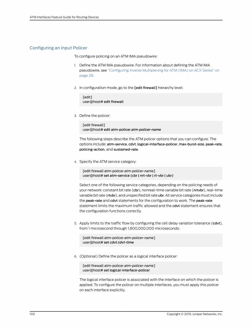
Configuring an Input Policer
To configure policing on an ATM IMA pseudowire:
1. Define the ATM IMA pseudowire. For information about defining the ATM IMA
pseudowire, see “Configuring Inverse Multiplexing for ATM (IMA) on ACX Series” on
page 28.
2. In configuration mode, go to the [edit firewall] hierarchy level:
[edit]user@host# edit firewall
3. Define the policer:
[edit firewall]user@host# edit atm-policer atm-policer-name
The following steps describe the ATM policer options that you can configure. The
options include: atm-service, cdvt, logical-interface-policer,max-burst-size, peak-rate,
policing-action, and sustained-rate.
4. Specify the ATM service category:
[edit firewall atm-policer atm-policer-name]user@host# set atm-service (cbr | nrt-vbr | rt-vbr | ubr)
Select one of the following service categories, depending on the policing needs of
your network: constant bit rate (cbr), nonreal-time variable bit rate (nrtvbr), real-time
variablebit rate (rtvbr), andunspecifiedbit rateubr. All service categoriesmust include
the peak-rate and cdvt statements for the configuration to work. The peak-rate
statement limits the maximum traffic allowed and the cdvt statement ensures that
the configuration functions correctly.
5. Apply limits to the traffic flow by configuring the cell delay variation tolerance (cdvt),
from 1 microsecond through 1,800,000,000microseconds:
[edit firewall atm-policer atm-policer-name]user@host# set cdvt cdvt-time
6. (Optional) Define the policer as a logical interface policer:
[edit firewall atm-policer atm-policer-name]user@host# set logical-interface-policer
The logical interface policer is associated with the interface on which the policer is
applied. To configure the policer onmultiple interfaces, youmust apply this policer
on each interface explicitly.
Copyright © 2019, Juniper Networks, Inc.100
ATM Interfaces Feature Guide for Routing Devices

7. (Optional) Define the maximum number of cells that a burst of traffic can contain,
from 1 through 4000 cells:
[edit firewall atm-policer atm-policer-name]user@host# setmax-burst-sizemax-burst-size
8. Apply limits to the traffic flow by specifying the largest number of cells per second
that the policer processes before it drops packets, from 61 cells per second (cps)
through 38,641 cps:
[edit firewall atm-policer atm-policer-name]user@host# set peak-rate peak-rate
Themaximumpeak rate value depends on the number of links in the IMAbundle—the
more links, the higher the possible peak rate.
9. Define thepolicing-actionparameter to setaconsequence for thepackets that exceed
the traffic limits:
[edit firewall atm-policer atm-policer-name]user@host# set policing-action (discard | discard-tag | count)
10. Define the normal traffic rate averaged over time, from 61 cps through 38,641 cps):
[edit firewall atm-policer atm-policer-name]user@host# set sustained-rate cps
After youhaveconfiguredpolicing, enter the commitcommand fromconfigurationmode.
Configuring the ATM IMA Interface
To create the ATM IMA interface on which to apply the ATM policer:
1. In configuration mode, go to the [edit interfaces] hierarchy level:
[edit]user@host# edit interfaces
2. Define the ATM interface:
[edit interfaces]user@host# edit at-fpc/pic/port
3. Specify the ATM interface unit:
[edit interfaces at-fpc/pic/port]user@host# edit unit logical-unit-number
101Copyright © 2019, Juniper Networks, Inc.
Chapter 2: Configuring ATM Interfaces

4. Apply the ATM policer:
[edit interfaces at-fpc/pic/port unit logical-unit-number]user@host# set atm-policer input-atm-policer policer-name
5. Specify the encapsulation family type:
[edit interfaces at-fpc/pic/port unit logical-unit-number]user@host# set family ccc
After you have configured the ATM IMA interface, enter the commit command in
configuration mode.
RelatedDocumentation
Understanding CoS on ATM IMA Pseudowire Interfaces Overview on page 16•
• Example: Configuring Policing on an ATM IMA Pseudowire on page 102
• Configuring Fixed Classification on an ATM IMA Pseudowire on page 89
• Configuring Shaping on an ATM IMA Pseudowire on page 93
Example: Configuring Policing on an ATM IMA Pseudowire
This example shows the configuration of policing on an ATM IMA pseudowire. On ACX
Series routers, the ATM policer is an input policer that is applied to the ATM IMA logical
interface. The ATM IMA logical interface must have the circuit cross-connect (CCC)
encapsulation family configured for the configuration to work.
NOTE: This example is not applicable on ACX5048 and ACX5096 routers.
• Requirements on page 102
• Overview on page 103
• Configuration on page 103
Requirements
This example uses the following hardware and software components:
• ACX Series router
• Junos OS Release 12.2 or later
• A previously configured ATM IMA pseudowire. For steps to configure an ATM IMA
pseudowire, see “Configuring Inverse Multiplexing for ATM (IMA) on ACX Series” on
page 28.
Copyright © 2019, Juniper Networks, Inc.102
ATM Interfaces Feature Guide for Routing Devices
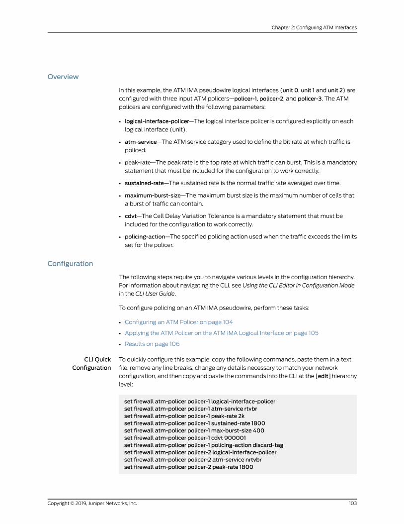
Overview
In this example, the ATM IMA pseudowire logical interfaces (unit 0, unit 1 and unit 2) are
configured with three input ATM policers—policer-1, policer-2, and policer-3. The ATM
policers are configured with the following parameters:
• logical-interface-policer—The logical interface policer is configured explicitly on each
logical interface (unit).
• atm-service—The ATM service category used to define the bit rate at which traffic is
policed.
• peak-rate—The peak rate is the top rate at which traffic can burst. This is a mandatory
statement that must be included for the configuration to work correctly.
• sustained-rate—The sustained rate is the normal traffic rate averaged over time.
• maximum-burst-size—Themaximum burst size is the maximum number of cells that
a burst of traffic can contain.
• cdvt—The Cell Delay Variation Tolerance is a mandatory statement that must be
included for the configuration to work correctly.
• policing-action—The specified policing action used when the traffic exceeds the limits
set for the policer.
Configuration
The following steps require you to navigate various levels in the configuration hierarchy.
For information about navigating the CLI, see Using the CLI Editor in Configuration Mode
in the CLI User Guide.
To configure policing on an ATM IMA pseudowire, perform these tasks:
• Configuring an ATM Policer on page 104
• Applying the ATM Policer on the ATM IMA Logical Interface on page 105
• Results on page 106
CLI QuickConfiguration
To quickly configure this example, copy the following commands, paste them in a text
file, remove any line breaks, change any details necessary to match your network
configuration, and then copyandpaste the commands into theCLI at the [edit] hierarchy
level:
set firewall atm-policer policer-1 logical-interface-policerset firewall atm-policer policer-1 atm-service rtvbrset firewall atm-policer policer-1 peak-rate 2kset firewall atm-policer policer-1 sustained-rate 1800set firewall atm-policer policer-1 max-burst-size 400set firewall atm-policer policer-1 cdvt 900001set firewall atm-policer policer-1 policing-action discard-tagset firewall atm-policer policer-2 logical-interface-policerset firewall atm-policer policer-2 atm-service nrtvbrset firewall atm-policer policer-2 peak-rate 1800
103Copyright © 2019, Juniper Networks, Inc.
Chapter 2: Configuring ATM Interfaces

set firewall atm-policer policer-2 sustained-rate 1500set firewall atm-policer policer-2max-burst-size 300set firewall atm-policer policer-2 cdvt 999991set firewall atm-policer policer-2 policing-action discardset firewall atm-policer policer-3 logical-interface-policerset firewall atm-policer policer-3 atm-service cbrset firewall atm-policer policer-3 peak-rate 2kset firewall atm-policer policer-3 cdvt 800001set firewall atm-policer policer-3 policing-action countset interfaces at-0/0/16 unit 0 atm-policer input-atm-policer policer-1set interfaces at-0/0/16 unit 0 family cccset interfaces at-0/0/16 unit 1 atm-policer input-atm-policer policer-2set interfaces at-0/0/16 unit 1 family cccset interfaces at-0/0/16 unit 2 atm-policer input-atm-policer policer-3set interfaces at-0/0/16 unit 2 family ccc
Configuring an ATMPolicer
Step-by-StepProcedure
To configure the ATM policer, which is applied to the logical ATM IMA pseudowire:
Define the policer:1.
[edit]user@host# edit firewall atm-policer policer-1
2. Specify the parameters for policer-1:
[edit firewall atm-policer policer-1]user@host# set logical-interface-policeruser@host# set atm-service rtvbruser@host# set peak-rate 2kuser@host# set sustained-rate 1800user@host# setmax-burst-size 400user@host# set cdvt 900001user@host# set policing-action discard-tag
3. Specify the parameters for policer-2:
[edit firewall atm-policer policer-2]user@host# set logical-interface-policeruser@host# set atm-service nrtvbruser@host# set peak-rate 1800user@host# set sustained-rate 1500user@host# setmax-burst-size 300user@host# set cdvt 999991user@host# set policing-action discard
4. Specify the parameters for policer-3:
[edit firewall atm-policer policer-3]
Copyright © 2019, Juniper Networks, Inc.104
ATM Interfaces Feature Guide for Routing Devices

user@host# set logical-interface-policeruser@host# set atm-service cbruser@host# set peak-rate 2kuser@host# set cdvt 999991user@host# set policing-action count
After you have configured the ATM policers, enter the commit command from
configuration mode.
Applying the ATMPolicer on the ATM IMA Logical Interface
Step-by-StepProcedure
To create the ATM IMA logical interface on which to apply the ATM policers:
Define the ATM interface:1.
[edit interfaces]user@host# edit interfaces at-0/0/16
2. Specify the ATM interface unit and apply the first input policer:
[edit interfaces at-0/0/16]user@host# set unit 0 atm-policer input-atm-policer policer-1
3. Specify the encapsulation family type for unit 0:
[edit interfaces at-0/0/16]user@host# set unit 0 family ccc
4. Specify the ATM interface unit and apply the second input policer:
[edit interfaces at-0/0/16]user@host# set unit 1 atm-policer input-atm-policer policer-2
5. Specify the encapsulation family type for unit 1:
[edit interfaces at-0/0/16]user@host# set unit 1 family ccc
6. Specify the ATM interface unit and apply the third input policer:
[edit interfaces at-0/0/16]user@host# set unit 2 atm-policer input-atm-policer policer-3
7. Specify the encapsulation family type for unit 2:
[edit interfaces at-0/0/16]
105Copyright © 2019, Juniper Networks, Inc.
Chapter 2: Configuring ATM Interfaces
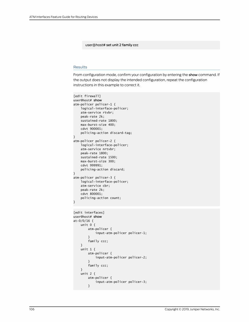
user@host# set unit 2 family ccc
Results
From configuration mode, confirm your configuration by entering the show command. If
the output does not display the intended configuration, repeat the configuration
instructions in this example to correct it.
[edit firewall]user@host# showatm-policer policer-1 { logical-interface-policer; atm-service rtvbr; peak-rate 2k; sustained-rate 1800; max-burst-size 400; cdvt 900001; policing-action discard-tag;}atm-policer policer-2 { logical-interface-policer; atm-service nrtvbr; peak-rate 1800; sustained-rate 1500; max-burst-size 300; cdvt 999991; policing-action discard;}atm-policer policer-3 { logical-interface-policer; atm-service cbr; peak-rate 2k; cdvt 800001; policing-action count;}
[edit interfaces]user@host# showat-0/0/16 { unit 0 { atm-policer { input-atm-policer policer-1; } family ccc; } unit 1 { atm-policer { input-atm-policer policer-2; } family ccc; } unit 2 { atm-policer { input-atm-policer policer-3; }
Copyright © 2019, Juniper Networks, Inc.106
ATM Interfaces Feature Guide for Routing Devices

family ccc; }}
After you have completed the configuration, enter the commit command from
configuration mode.
RelatedDocumentation
Understanding CoS on ATM IMA Pseudowire Interfaces Overview on page 16•
• Configuring Policing on an ATM IMA Pseudowire on page 99
• Example: Configuring Fixed Classification on an ATM IMA Pseudowire on page 90
• Example: Configuring Shaping on an ATM IMA Pseudowire on page 95
Defining the ATMTraffic-Shaping Profile Overview
When you use an ATM encapsulation on ATM1 and ATM2 IQ interfaces, you can define
bandwidth utilization, which consists of either a constant rate or a peak cell rate, with
sustained cell rate and burst tolerance.
These values are used in the ATM generic cell-rate algorithm, which is a leaky bucket
algorithm that defines the short-term burst rate for ATM cells, the maximum number of
cells that can be included in a burst, and the long-term sustained ATM cell traffic rate.
If your router is equipped with an ATM2 IQ PIC, each VC can have independent shaping
parameters. For more information, see “Defining Virtual Path Tunnels” on page 113.
NOTE: When the DS3 or E3 port parameters are not identical on all ports ofamultiport ATMDS3 or E3 PIC, the ATM PIC driver might not always use theminimum port shaping rate (of all the ports on amultiport ATMDS3 or E3PIC) selected for cell transmission shaping. The PIC's shaping rate is alwaysupdated to conform to the last port setting updated by the PIC softwaredriver, rather than use theminimum port (shaping) rate. There is no syslogmessage to inform the user of the shaping rate decision applied by thesoftware driver.
By default, the bandwidth utilization is unlimited; that is, unspecified bit rate (UBR) is
used. Also, by default, buffer usage by VCs is unregulated.
To define limits to bandwidth utilization, include the shaping statement:
shaping {(cbr rate | rtvbr peak rate sustained rate burst length | vbr peak rate sustained rate burstlength);
queue-length number;}
107Copyright © 2019, Juniper Networks, Inc.
Chapter 2: Configuring ATM Interfaces

For a list of hierarchy levels at which you can include this statement, see shaping.
The rtvbr statement is supported on ATM2 IQ PICs only. The queue-length statement is
supported on ATM1 PICs only.
To configure VP tunnels on ATM2 IQ interfaces, include the shaping statement at the
[edit interfaces interface-name atm-options vpi vpi-identifier] hierarchy level:
[edit interfaces interface-name atm-options vpi vpi-identifier]shaping {(cbr rate | rtvbr peak rate sustained rate burst length | vbr peak rate sustained rate burstlength);
}
When configuring ATM traffic shaping, you can do the following:
• Configuring ATM CBR on page 108
• Configuring ATM2 IQ Real-Time VBR on page 109
• Configuring ATM VBR on page 109
• Specifying ATM1 Shaping Values on page 110
• Specifying ATM2 IQ Shaping Values on page 113
Configuring ATMCBR
For traffic that does not require the ability to periodically burst to a higher rate, you can
specify a constant bit rate (CBR).
To specify a CBR on ATM1 and ATM2 IQ interfaces, include the cbr statement:
cbr rate;
For a list of hierarchy levels at which you can include this statement, see cbr.
For ATM1 OC3 interfaces, the rate can be from 33 Kbps through 135.6 Mbps; for ATM1
OC12 interfaces, the rate can be from 33 Kbps through 276 Mbps.
For ATM2 IQ OC3 and OC12 interfaces, the rate can be from 33 Kbps through
542,526,792 bps.
For ATM2 IQ OC48 interfaces, the rate can be from 33 Kbps through 2,170,107,168 bps.
For ATM2 IQ DS3 and E3 interfaces, the rate can be from 33 Kbps to the maximum rate.
Themaximumratevariesdependingon theATMencapsulationand framingyouconfigure,
as shown in Table 12 on page 108.
Table 12: Shaping Rate Range by Interface Type
MaximumRateInterface Type
40,038,968 bpsDS3 with direct ATM encapsulation
36,864,000 bpsDS3 with PLCP ATM encapsulation
Copyright © 2019, Juniper Networks, Inc.108
ATM Interfaces Feature Guide for Routing Devices

Table 12: Shaping Rate Range by Interface Type (continued)
MaximumRateInterface Type
30,801,509 bpsE3 with g.751 framing and direct ATMencapsulation
27,648,000 bpsE3 with g.751 framing PLCP ATMencapsulation
30,720,000 bpsE3 with g.832 framing
Configuring ATM2 IQ Real-Time VBR
By default, ATM interfaces use UBR; that is, bandwidth utilization is unlimited. For ATM2
IQ interfaces only, you can configure RTVBR, which supports variable bit rate data traffic
with average and peak traffic parameters. Compared to non-real-timeVBR, RTVBRdata
is serviced at a higher priority with a relatively small sustainable cell rate (SCR) limit to
minimize the delay. Real-time VBR is suitable for carrying packetized video and audio.
To configure RTVBR, include the rtvbr statement:
rtvbr peak rate sustained rate burst length;
For a list of hierarchy levels at which you can include this statement, see rtvbr.
When configuring RTVBR, you can define the following shaping properties:
• Peak rate—Top rate at which traffic can burst.
• Sustained rate—Normal traffic rate averaged over time.
• Burst length—Maximum number of cells that a burst of traffic can contain. It can be a
value from 1 through 4000 cells.
The peak and sustained rates can be from 33 Kbps through 542,526,792 bps.
Configuring ATMVBR
By default, ATM interfaces use UBR; that is, bandwidth utilization is unlimited. For ATM1
and ATM2 IQ interfaces, you can configure non-real-time VBR, which supports variable
bit rate data traffic with average and peak traffic parameters. Compared to RTVBR,
non-real-timeVBR is scheduledwith a lower priority andwith a larger SCR limit, allowing
it to recover bandwidth if it falls behind. Non-real-time VBR is suitable for packet data
transfers.
To define VBR on ATM1 and ATM2 IQ interfaces, include the vbr statement:
vbr peak rate sustained rate burst length;
For a list of hierarchy levels at which you can include this statement, see vbr.
109Copyright © 2019, Juniper Networks, Inc.
Chapter 2: Configuring ATM Interfaces

When configuring VBR, you can define the following shaping properties:
• Peak rate—Top rate at which traffic can burst.
• Sustained rate—Normal traffic rate averaged over time.
• Burst length—Maximum number of cells that a burst of traffic can contain. It can be a
value from 1 through 4000 cells.
Specifying ATM1 Shaping Values
For ATM1 interfaces, you can specify the rates in bits per second or cells per second. For
OC3c interfaces, thehighest rate is 135,631,698bps (353,207.55cps),which corresponds
to 100 percent of the available line rate. For OC12c interfaces, the highest rate is
271,263,396 bps (706,415.09 cps), which corresponds to 50 percent of the available line
rate. Table 13 on page 111 lists some of the other rates you can specify. If you specify a
rate that is not listed, it is rounded to the nearest rate.
Theexactnumberof valuesdiffersbetweenOC12candOC3c interfaces.OC12c interfaces
have about four times as many value increments as OC3c interfaces.
For OC12c rates between 1/2 of the line rate and 1/128 of the line rate, there are 128 steps
between each 1/n value. This means that there is 128 steps between the 1/2 and 1/3 line
rate values, and another 128 steps between 1/3 and 1/4 and so on. For rates smaller than
1/127, there are (16,384minus 127) or 16, 257 values. The reason for this is that fractional
shaping is ignored at rates below 1/127. This results in a total of about 32,384 distinct
rates for OC12c. When n is larger than or equal to 127, the steps are 1/n.
For OC3c, the starting point is full line rate, the fraction/integer breakpoint is about 1/31,
and there is amaximum of 4096 scheduler slots for use after 1/31 of line rate, producing
about 8032 total distinct rates. When n is larger than or equal to 31, the steps are 1/n.
For ATM1 interfaces, the following formula can be used to predict the actual shaping
rate:
• OC3 shaping settings between 135,631,698 bps (OC3ATMcell line rate) and 4,375,216
bps (1/31 of OC3 ATM cell line rate).
• OC12 shaping settings between 271,263,396 bps (half OC12 ATM cell line rate – the
highest rate supported) and 4,271,864 bps (1/127 of OC12 ATM cell line rate).
actual-rate = (128 * line-rate) / (trunc ((128 * line-rate) / desired-rate))
line-rate is themaximumavailable rateon the interface (inbits per second)after factoring
out the overhead for SONET/SDH and ATM (per-cell) overheads. For OC3c interfaces,
the line rate is calculated as follows:
line-rate = 155,520,000 bps *(26/27) * (48/53) = 135,631,698.1 bps
For OC12c interfaces, the line rate is calculated as follows:
line-rate = 622,080,000 bps * (26/27) * (48/53) = 542,526,792.45 bps
Copyright © 2019, Juniper Networks, Inc.110
ATM Interfaces Feature Guide for Routing Devices

desired-rate is the rate you enter in the vbr statement, in bits per second.
The trunc operator indicates that all digits to the right of the decimal point should be
dropped.
For shaping settings smaller than 1/31 of OC3ATMcell line rate (4,375,216 bps) and 1/127
of OC12 ATM cell line rate (4,271,864 bps), you can predict the actual shaping rate using
the following formula:
actual-rate = ( 1 / ( trunc ( line-rate / desired-rate ) +1 ) ) * line-rate
For example, for OC12 interfaces, the actual rates for shaping below 4,271,864 bps are
calculated as follows:
1 / 127 * 542,526,792.45 bps = 4,271,864 bps (11124 cells/second)1 / 128 * 542,526,792.45 bps = 4,238,490 bps (11038 cells/second)1 / 129 * 542,526,792.45 bps = 4,205,634 bps (10952 cells/second)...
Buffers are shared among all VCs, and by default, there is no limit to the buffer size for
a VC. If a VC is particularly slow, it might use all the buffer resources.
Table 13 on page 111 shows ATM1 traffic-shaping rates.
Table 13: ATM1 Traffic-Shaping Rates
Percentage of TotalLine RateLine Rate (cps)Line Rate (bps)
InterfaceType
OC3
100.00353,125135,600,000
99.22350,370.66134,542,320
98.46347,686.88133,511,760
97.71345,038.44132,494,760
96.97342,425.31131,491,320
96.24339,847.5130,501,440
95.52337,305129,525,120
94.81334,797.81128,562,360
94.12332,361.25127,626,720
93.43329,924.69126,691,080
OC12
111Copyright © 2019, Juniper Networks, Inc.
Chapter 2: Configuring ATM Interfaces

Table 13: ATM1 Traffic-Shaping Rates (continued)
Percentage of TotalLine RateLine Rate (cps)Line Rate (bps)
InterfaceType
50.00706,415.09271,263,396
49.81703,666.40270,207,897
49.61700,939.01269,160,579
49.42698,232.68268,121,349
49.23695,547.17267,090,113
49.04692,882.24266,066,779
48.85690,237.65265,051,257
48.67687,613.17264,043,458
48.48685,008.58263,043,293
48.30682,423.64262,050,677
Example: Specifying ATM1 Shaping Values
Determine the actual rate in ATM1 interfaces when the desired rate is 80 percent of the
maximum rate:
• OC3c:
135,600,000 bps * 0.8 = 108,480,000 bps
Because 108,480,000 bps is greater than 1/31 of OC3 ATM cell line rate:
actual-rate = (128 * 135,600,000.1) / (trunc ((128 * 135,600,000.1) / 108,480,000))actual-rate = 17,356,800,013 / (trunc (17,356,800,013 / 108,480,000))actual-rate = 17,356,800,013 / 160actual-rate = 108,480,000 bps
• OC12c:
271,263,396 bps * 0.8 = 217,010,716.8 bps
Because 217,010,716.8 bps is greater than 1/127 of OC12 ATM cell line rate:
actual-rate = (128 * 542,526,792.45) / (trunc ((128 * 542,526,792.45)/217,010,716.8))actual-rate = 69,443,429,434 / (trunc (69,443,429,434 / 217,010,716.8))actual-rate = 69,443,429,434 / 320actual-rate = 217,010,717 bps
Copyright © 2019, Juniper Networks, Inc.112
ATM Interfaces Feature Guide for Routing Devices

Determine the actual rate in ATM1 interfaces when the desired rate is 3,000,000 bps:
• OC3c:
Because 3,000,000 bps is smaller than 1/31 of OC3 ATM cell line rate:
actual-rate= ( 1 / ( trunc ( line-rate / desired-rate ) + 1 ) ) * line-rateactual-rate = ( 1 / ( trunc ( 135,631,698 / 3,000,000 ) + 1 ) ) * 135,631,698actual-rate = ( 1 / ( 45 + 1 ) ) * 135,631,698actual-rate = ( 1 / 46 ) * 135,631,698actual-rate = 2,948,515 bps
• OC12c:
Because 3,000,000 bps is smaller than 1/127 of OC12 ATM cell line rate:
actual-rate = ( 1 / ( trunc ( line-rate / desired-rate ) + 1 ) ) * line-rateactual-rate = ( 1 / ( trunc (542,526,792 / 3,000,000 ) + 1 ) ) * 542,526,792actual-rate = ( 1 / ( 180 + 1 ) ) * 542,526,792actual-rate = ( 1 / 181 ) * 542,526,792actual-rate = 2,997,386 bps
Specifying ATM2 IQ Shaping Values
For ATM2 IQ OC3c interfaces, the maximum available rate is 100 percent of line rate, or
135,600,000 bps. For ATM2 IQ OC12c interfaces, the maximum available rate is 50
percent of line rate, or 271,273,396 bps. You can specify the rates in bits per second or
cells per second. Fractional shaping is accurate within 0.5 percent of the desired rate.
Defining Virtual Path Tunnels
For ATM2 IQ interfaces, you can configure shaping on a VPI. When you do this, the VPI is
called a VP tunnel. If your router is equipped with an ATM2 IQ PIC, you can configure VP
tunnels and a weight for each VC. Each VC is serviced inWRRmode. When VCs have
data to send, they send the number of cells equal to their weight before passing control
to the next active VC. This allows proportional bandwidth sharing betweenmultiple VCs
within a rate-shaped VP tunnel. VP tunnels are not supported on point-to-multipoint
interfaces.
If you change or deleteVP tunnel traffic shaping, all logical interfaces on aVPare deleted
and re-added.
All VPIs you configure on logical interfaces must also be configured on the physical
interface, at the [edit interfaces interface-name atm-options] hierarchy level.
WhenyouconfigureaVPIwithout shapingparameters, theVPI is a regularVPI; no shaping
is attached. VCIs that belong to non-shaped VPIs can have VCI shaping.
For point-to-point interfaces, include the shaping statement at the [edit interfaces
interface-name atm-options vpi vpi-identifier] hierarchy level:
[edit interfaces interface-name atm-options vpi vpi-identifier]
113Copyright © 2019, Juniper Networks, Inc.
Chapter 2: Configuring ATM Interfaces

shaping {(cbr rate | rtvbr peak rate sustained rate burst length | vbr peak rate sustained rate burstlength);
queue-length number;}
For cbr, vbr, andburst statement usageguidelines, see “Defining theATMTraffic-Shaping
ProfileOverview”onpage 107. For informationaboutATM2 IQshapingvalues, seeDefining
the ATM Traffic-Shaping Profile Overview.
Configuring the ATM1 Queue Length
ATM1 PICs contain a transmit buffer pool of 16,382 buffers, which are shared by all the
PVCs that you configure on the PIC. Evenmultiple-port ATM PICs have a single buffer
pool shared by all the ports.
By default, the ATM1 PIC allows PVCs to consume all the buffers they require. If the
sustained traffic rate for aPVCexceeds its shaped rate, buffersare consumed. Eventually,
all buffers on the PIC are consumed, and the other PVCs are underserved. This results in
head-of-line blocking.
For each PVC, you prevent this situation by configuring the queue length of the PVC. The
queue length is a limit on the number of transmit packets that can be queued. Packets
that exceed the limit are dropped.
To limit the queue size of a PVC, include the queue-length statement:
queue-length number;
For a list of hierarchy levels at which you can include this statement, see queue-length.
The length can be from 1 through 16,383 packets. The default is 16,383 packets. You
should include the queue-length statement in the configuration of all the PVCs that you
configure on an ATM1 PIC. The queue-length statement performs two functions:
• It prevents head-of-lineblockingbecause it limits thenumber of packets and therefore
buffers that can be consumed by each configured PVC.
• It sets the maximum lifetime that can be sustained by packets over the PVCwhen
traffic has oversubscribed the configured shaping contract.
The total value of all the queue lengths must not exceed the total number of packets
that can be held in the buffer space available on the PIC. The total number of packets
the buffers can hold depends on the size of the physical interface MTU, including all
encapsulation overhead. You canuse the following formula to calculate the total number
of packets the buffer space can hold:
16,382 / ( Round Up ( MTU / 480 ) )
For example, assuming default MTU settings for all ATM1 interfaces on a PIC, the total
number of packets that can be held is:
Copyright © 2019, Juniper Networks, Inc.114
ATM Interfaces Feature Guide for Routing Devices

16,382 / ( Round Up ( 4482 / 480 ) ) = 1638 packets
Thus, you can configure up to 1638 for the combined queue length of all the PVCs on an
ATM1 PIC that uses default MTU settings for all interfaces.
If you set a queue length to a very low value, small bursts in packets transiting the PVC
might not be buffered.
Themaximum lifetime that packets can sustain while transiting a PVC depends on the
shaping rate you configure for the PVC, the setting for the queue-length statement, and
the physical interfaceMTU. You can use the following formula to calculate themaximum
lifetime that packets can sustain while transiting a PVC:
( PVC queue-length in packets x MTU ) / ( PVC shaping in bps / 8 )
For example, if you configure a PVC on an ATM1 interface with the default MTU, a CBR
shaping rate of 3,840,000 bps (10,000 cps), and a queue length of 25 packets. The
maximum lifetime is:
( 25 x 4482 ) / ( 3,840,000 / 8 ) = 233ms
This is the worst-case lifetime assuming all packets in the queue are MTU sized, and the
traffic using the PVC is oversubscribing its configured shaping contract.
In general, we recommend that you use amaximum lifetime under 500ms.
If you add or change the queue-length setting on the VC, the logical interface associated
with the VC is deleted and re-added.
Configuring a Point-to-Point ATM1 or ATM2 IQ Connection
When you use ATM encapsulation on an interface, youmust map each logical interface
to a VCI. You can optionally map logical interfaces to a VPI.
For ATM1 and ATM2 IQ interfaces, you can configure a VCI and a VPI on a point-to-point
ATM interface by including the vci statement:
vci vpi-identifier.vci-identifier;
You can include this statement at the following hierarchy levels:
• [edit interfaces interface-name unit logical-unit-number]
• [edit logical-systems logical-system-name interfaces interface-name unit
logical-unit-number]
For each VCI, configure the VCI and VPI identifiers. The default VPI identifier is 0. For
ATM1 interfaces, the VCI identifier cannot exceed the highest-numbered VC configured
for the interface with the vpi statement, as described in “Configuring the Maximum
Number of ATM1 VCs on a VP” on page 46.
VCIs 0 through 31 are reserved for specific ATM values designated by the ATM Forum.
115Copyright © 2019, Juniper Networks, Inc.
Chapter 2: Configuring ATM Interfaces

ATM2 IQ interfaces support only one invalid VC counter for all ports. The invalid VC
counter is recorded at port 0 only.
When you are configuring point-to-point connections, the maximum transmission unit
(MTU) sizes on both sides of the connections must be the same.
Configuring a Point-to-Multipoint ATM1 or ATM2 IQ Connection
An ATM interface can be a point-to-point interface or a point-to-multipoint (also called
amultipoint non-broadcast multiaccess [NBMA]) connection.
For ATM1 and ATM2 IQ interfaces, you can configure an NBMA ATM connection by
including the following statements:
multipoint;family inet {address ip-address {multipoint-destination address {epd-threshold cells;inverse-arp;oam-liveness {up-count cells;down-count cells;
}oam-period (disable | seconds);shaping {(cbr rate | rtvbr peak rate sustained rate burst length | vbr peak rate sustained rateburst length);
queue-length number;}vci vpi-identifier.vci-identifier;
}}
}
ip-address is the interface’s address. The addressmust include the destination prefix (for
example, /24).
You can include this statement at the following hierarchy levels:
• [edit interfaces interface-name unit logical-unit-number]
• [edit logical-systems logical-system-name interfaces interface-name unit
logical-unit-number ]
For eachdestination, includeonemultipoint-destination statement.address is theaddress
of the remote side of the connection, and vci-identifier and vpi-identifier are the VCI and
optional VPI identifiers for the connection.
When you configure point-to-multipoint connections, all interfaces in the subnet must
use the sameMTU size.
Copyright © 2019, Juniper Networks, Inc.116
ATM Interfaces Feature Guide for Routing Devices

Configuring Inverse ATM1 or ATM2 ARP
For ATM1 and ATM2 IQ interfaces, you can configure inverse ATM Address Resolution
Protocol (ARP), as described in RFC 2225, Classical IP and ARP over ATM. When inverse
ATM ARP is enabled, the router responds to received inverse ATM ARP requests by
providing IP address information to the requesting ATM device.
The router does not initiate inverse ATM ARP requests.
By default, inverse ATM ARP is disabled. To configure a VC to respond to inverse ATM
ARP requests, include the inverse-arp statement:
inverse-arp;
For a list of hierarchy levels at which you can include this statement, see inverse-arp.
Youmust configure ATM LLC subnetwork attachment point (SNAP) encapsulation on
the logical interface to support inverse ARP. No other ATM encapsulation types are
allowed. Formore information, see “ConfiguringATM InterfaceEncapsulation” onpage51.
ATM2 IQ VC Tunnel CoS Components Overview
The ATM2 IQ interface allowsmultiple IP queues into each VC. On M Series routers
(except the M320 and M120 router), a VC tunnel can support four CoS queues. On the
M320, M120, and T Series routers for all ATM2 IQ PICs except the OC48 PIC, a VC tunnel
can support eight CoSqueues.Within a VC tunnel, theWRRalgorithm schedules the cell
transmission of each queue. You can configure the queue admission policies, such as
EPD orWRED, to control the queue size during congestion.
For information about CoS components that apply to all interfaces, see the Class of
Service Feature Guide for Routers and EX9200 Switches.
• Configuring ATM2 IQ VC Tunnel CoS Components on page 118
• Configuring Linear RED Profiles on page 118
• Configuring an ATM Scheduler Map on page 119
• Enabling Eight Queues on ATM2 IQ Interfaces on page 121
• Example: Enabling Eight Queues on T Series, M120, and M320 Routers on page 122
• Configuring VC CoSMode on page 126
• Enabling the PLP Setting to Be Copied to the CLP Bit on page 127
• Configuring ATM CoS on the Logical Interface on page 127
• Example: Configuring ATM2 IQ VC Tunnel CoS Components on page 128
117Copyright © 2019, Juniper Networks, Inc.
Chapter 2: Configuring ATM Interfaces

Configuring ATM2 IQ VC Tunnel CoS Components
To configure ATM2 IQ VC tunnel CoS components, include the following statements at
the [edit interfaces at-fpc/pic/port] hierarchy level:
[edit chassis fpc slot-number pic pic-number]max-queues-per-interface number;[edit interfaces at-fpc/pic/port]atm-options {linear-red-profiles profile-name {high-plp-max-threshold percent;low-plp-max-threshold percent;queue-depth cells high-plp-threshold percent low-plp-threshold percent;
}plp-to-clp;scheduler-mapsmap-name {forwarding-class class-name {epd-threshold cells plp1 cells;linear-red-profile profile-name;priority (high | low);transmit-weight (cells number | percent number);
}vc-cos-mode (alternate | strict);
}}unit 0 {atm-scheduler-map (map-name | default);family family {address address {destination address;
}}plp-to-clp;shaping {(cbr rate | rtvbrpeak rate sustained rateburst length | vbrpeak rate sustained rateburstlength);
}vci vpi-identifier.vci-identifier;
}
This section contains the following topics:
Configuring Linear RED Profiles
Linear RED profiles define CoS virtual circuit drop profiles. You can configure up to 32
linear RED profiles per port. When a packet arrives, RED checks the queue fill level. If the
fill level corresponds toanonzerodropprobability, theREDalgorithmdetermineswhether
to drop the arriving packet.
To configure linear RED profiles, include the linear-red-profiles statement at the [edit
interfaces at-fpc/pic/port atm-options] hierarchy level:
[edit interfaces at-fpc/pic/port atm-options]
Copyright © 2019, Juniper Networks, Inc.118
ATM Interfaces Feature Guide for Routing Devices
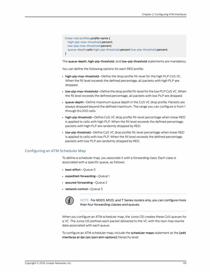
linear-red-profiles profile-name {high-plp-max-threshold percent;low-plp-max-threshold percent;queue-depth cells high-plp-threshold percent low-plp-threshold percent;
}
The queue-depth, high-plp-threshold, and low-plp-threshold statements aremandatory.
You can define the following options for each RED profile:
• high-plp-max-threshold—Define the drop profile fill-level for the high PLP CoS VC.
When the fill level exceeds the defined percentage, all packets with high PLP are
dropped.
• low-plp-max-threshold—Define thedropprofile fill-level for the lowPLPCoSVC.When
the fill level exceeds the defined percentage, all packets with low PLP are dropped.
• queue-depth—Define maximum queue depth in the CoS VC drop profile. Packets are
always dropped beyond the definedmaximum. The range you can configure is from 1
through 64,000 cells.
• high-plp-threshold—Define CoS VC drop profile fill-level percentage when linear RED
is applied to cells with high PLP. When the fill level exceeds the defined percentage,
packets with high PLP are randomly dropped by RED.
• low-plp-threshold—Define CoS VC drop profile fill-level percentage when linear RED
is applied to cells with low PLP. When the fill level exceeds the defined percentage,
packets with low PLP are randomly dropped by RED.
Configuring an ATMScheduler Map
To define a scheduler map, you associate it with a forwarding class. Each class is
associated with a specific queue, as follows:
• best-effort—Queue 0
• expedited-forwarding—Queue 1
• assured-forwarding—Queue 2
• network-control—Queue 3
NOTE: For M320, M120, and T Series routers only, you can configuremorethan four forwarding classes and queues.
When you configure an ATM scheduler map, the Junos OS creates these CoS queues for
a VC. The Junos OS prefixes each packet delivered to the VC with the next-hop rewrite
data associated with each queue.
To configure an ATM scheduler map, include the scheduler-maps statement at the [edit
interfaces at-fpc/pic/port atm-options] hierarchy level:
119Copyright © 2019, Juniper Networks, Inc.
Chapter 2: Configuring ATM Interfaces

edit interfaces at-fpc/pic/port atm-options]scheduler-mapsmap-name {forwarding-class class-name {epd-threshold cells plp1 cells;linear-red-profile profile-name;priority (high | low);transmit-weight (cells number | percent number);
}}
You can define the following options for each forwarding class:
• epd-threshold or linear-red-profile—An EPD threshold provides a queue of cells that
can be stored with tail drop. When a BOP cell is received, the VC’s queue depth is
checkedagainst theEPDthreshold. If theVC’squeuedepthexceeds theEPDthreshold,
the BOP cell and all subsequent cells in the packet are discarded.
A linear RED profile defines the number of cells using the queue-depth statement within
the RED profile. (You configure the queue-depth statement at the [edit interfaces
at-fpc/pic/port atm-options linear-red-profiles profile-name] hierarchy level.)
By default, if you include the scheduler-maps statement at the [edit interfaces
at-fpc/pic/port atm-options] hierarchy level, the interface uses an EPD threshold that is
determined by the Junos OS based on the available bandwidth and other parameters.
You can override the default EPD threshold by setting an EPD threshold or a linear RED
profile.
• priority—Bydefault, queue0 is high-priority, and the remaining queues are low-priority.
You can configure high or low queuing priority for each queue.
• transmit-weight—By default, the transmit weight is 95 percent for queue 0, and
5 percent for queue 3. You can configure the transmission weight in number of cells or
percentage. Each CoS queue is serviced inWRRmode. When CoS queues have data
to send, they send the number of cells equal to their weight before passing control to
the next active CoS queue. This allows proportional bandwidth sharing between
multiple CoS queues within a rate-shaped VC tunnel. A CoS queue can send from
1 through 32,000 cells or from 5 through 100 percent of queued traffic before passing
control to the next active CoS queue within a VC tunnel.
The AAL5 protocol prohibits cells from being interleaved on a VC; therefore, a complete
packet is always sent. If a CoS queue sendsmore cells than its assignedweight because
of the packet boundary, the deficit is carried over to the next time the queue is scheduled
to transmit. If the queue is empty after the cells are sent, the deficit is waived, and the
queue’s assigned weight is reset.
Copyright © 2019, Juniper Networks, Inc.120
ATM Interfaces Feature Guide for Routing Devices

NOTE: If you include the scheduler-maps statement at the [edit interfaces
at-fpc/pic/port atm-options] hierarchy level, the epd-threshold statement at
the [edit interfaces interface-name unit logical-unit-number] or [edit interfaces
interface-name unit logical-unit-number address address family family
multipoint-destination address] hierarchy level has no effect because either
the default EPD threshold, the EPD threshold setting in the forwarding class,or the linear RED profile takes effect instead.
For more information about forwarding classes, see the Class of Service Feature Guide
for Routers and EX9200 Switches.
Enabling Eight Queues on ATM2 IQ Interfaces
Bydefault, ATM2 IQPICsonTSeries,M120, andM320 routersare restricted toamaximum
of four egress queues per interface. You can enable eight egress queues on ATM2 IQ
interfaces by including themax-queues-per-interface statement at the [edit chassis fpc
slot-number pic pic-number] hierarchy level:
[edit chassis fpc slot-number pic pic-number]max-queues-per-interface number;
The numerical value can be 4 or 8.
If you include themax-queues-per-interface statement, all ports on the ATM2 IQ PIC use
the configuredmode.
Whenyou include themax-queues-per-interfacestatementandcommit theconfiguration,
all physical interfaces on the ATM2 IQ PIC are deleted and re-added. Also, the PIC is
taken offline and then brought back online immediately. You do not need to manually
take thePICofflineandonline. You should changemodesbetween four queuesandeight
queues, or vice versa, only when there is no active traffic going to the ATM2 IQ PIC.
For general information about configuring up to eight forwarding classes and queues on
PICs other than ATM2 IQ PICs, see the Class of Service Feature Guide for Routers and
EX9200 Switches.
121Copyright © 2019, Juniper Networks, Inc.
Chapter 2: Configuring ATM Interfaces

NOTE: When you are considering enabling eight queues on an ATM2 IQinterface, you should note the following:
• ATM2 IQ interfaces using Layer 2 circuit trunk transportmode support onlyfour CoS queues.
• ATM2 IQ OC48 interfaces support only four CoS queues.
• ATM2 IQ interfaces with MLPPP encapsulation support only four CoSqueues.
• Youcanconfigureonly fourREDprofiles for theeightqueues.Thus, queue0andqueue 4 share a single REDprofile, as do queue 1 and queue 5, queue 2and queue 6, and queue 3 and queue 7. There is no restriction on EPDthreshold per queue.
• The default chassis scheduler allocates resources for queue 0 throughqueue 3, with 25 percent of the bandwidth allocated to each queue.Whenyouconfigure thechassis tousemore than fourqueues, youmustconfigureand apply a custom chassis scheduler to override the default. To apply acustom chassis scheduler, include the scheduler-map-chassis statement
at the [edit class-of-service interfacesat-fpc/pic/*]hierarchy level. Formore
information about configuring and applying a custom chassis scheduler,see the Class of Service Feature Guide for Routers and EX9200 Switches.
Example: Enabling Eight Queues on T Series, M120, andM320 Routers
InFigure4onpage 122,RouterAgenerates IPpacketswithdifferent IPprecedencesettings.
Router B is an M320, M120, or T Series router with two ATM2 IQ interfaces. On Router B,
interface at-6/1/0 receives traffic from Router A, while interface at-0/1/0 sends traffic
to Router C. This example shows the CoS configuration for Router B.
Figure 4: Example Topology for Router with Eight Queues
On Router B:
[edit chassis]fpc 0 {pic 1 {max-queues-per-interface 8;
}}fpc 6 {pic 1 {max-queues-per-interface 8;
}}
Copyright © 2019, Juniper Networks, Inc.122
ATM Interfaces Feature Guide for Routing Devices

[edit interfaces]at-0/1/0 {atm-options {linear-red-profiles {red_1 queue-depth 1k high-plp-threshold 50 low-plp-threshold 80;red_2 queue-depth 2k high-plp-threshold 40 low-plp-threshold 70;red_3 queue-depth 3k high-plp-threshold 30 low-plp-threshold 60;red_4 queue-depth 4k high-plp-threshold 20 low-plp-threshold 50;
}scheduler-maps {sch_red {vc-cos-mode strict;forwarding-class fc_q0 {priority high;transmit-weight percent 5;linear-red-profile red_1;
}forwarding-class fc_q1 {priority low;transmit-weight percent 10;linear-red-profile red_2;
}forwarding-class fc_q2 {priority low;transmit-weight percent 15;linear-red-profile red_3;
}forwarding-class fc_q3 {priority low;transmit-weight percent 20;linear-red-profile red_4;
}forwarding-class fc_q4 {priority low;transmit-weight percent 5;linear-red-profile red_1;
}forwarding-class fc_q5 {priority low;transmit-weight percent 10;linear-red-profile red_2;
}forwarding-class fc_q6 {priority low;transmit-weight percent 15;linear-red-profile red_3;
}forwarding-class fc_q7 {priority low;transmit-weight percent 20;linear-red-profile red_4;
}}sch_epd {vc-cos-mode alternate;
123Copyright © 2019, Juniper Networks, Inc.
Chapter 2: Configuring ATM Interfaces
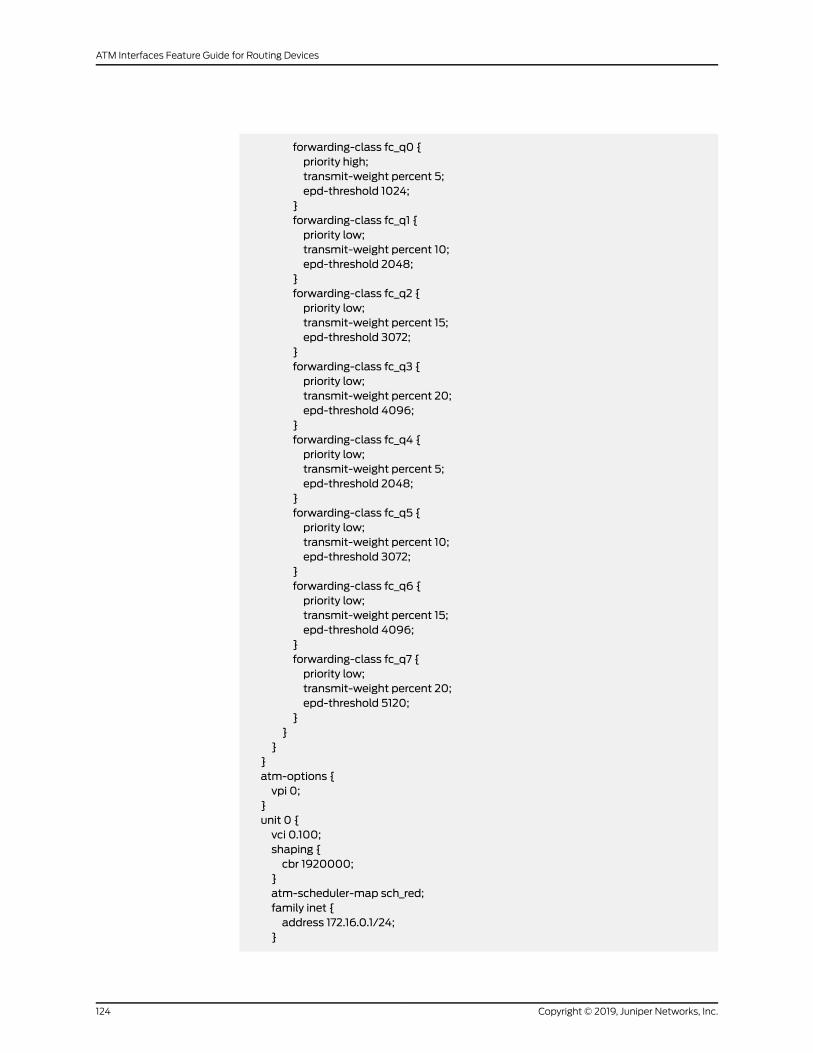
forwarding-class fc_q0 {priority high;transmit-weight percent 5;epd-threshold 1024;
}forwarding-class fc_q1 {priority low;transmit-weight percent 10;epd-threshold 2048;
}forwarding-class fc_q2 {priority low;transmit-weight percent 15;epd-threshold 3072;
}forwarding-class fc_q3 {priority low;transmit-weight percent 20;epd-threshold 4096;
}forwarding-class fc_q4 {priority low;transmit-weight percent 5;epd-threshold 2048;
}forwarding-class fc_q5 {priority low;transmit-weight percent 10;epd-threshold 3072;
}forwarding-class fc_q6 {priority low;transmit-weight percent 15;epd-threshold 4096;
}forwarding-class fc_q7 {priority low;transmit-weight percent 20;epd-threshold 5120;
}}
}}atm-options {vpi 0;
}unit 0 {vci 0.100;shaping {cbr 1920000;
}atm-scheduler-map sch_red;family inet {address 172.16.0.1/24;
}
Copyright © 2019, Juniper Networks, Inc.124
ATM Interfaces Feature Guide for Routing Devices
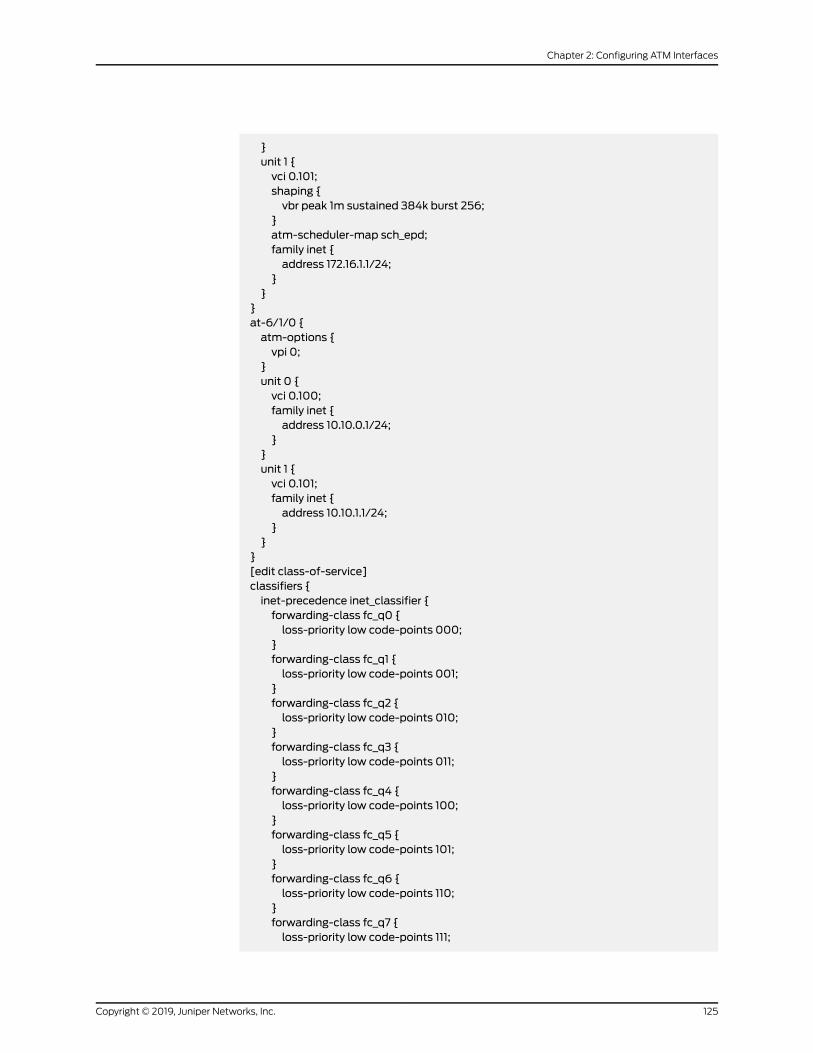
}unit 1 {vci 0.101;shaping {vbr peak 1m sustained 384k burst 256;
}atm-scheduler-map sch_epd;family inet {address 172.16.1.1/24;
}}
}at-6/1/0 {atm-options {vpi 0;
}unit 0 {vci 0.100;family inet {address 10.10.0.1/24;
}}unit 1 {vci 0.101;family inet {address 10.10.1.1/24;
}}
}[edit class-of-service]classifiers {inet-precedence inet_classifier {forwarding-class fc_q0 {loss-priority low code-points 000;
}forwarding-class fc_q1 {loss-priority low code-points 001;
}forwarding-class fc_q2 {loss-priority low code-points 010;
}forwarding-class fc_q3 {loss-priority low code-points 011;
}forwarding-class fc_q4 {loss-priority low code-points 100;
}forwarding-class fc_q5 {loss-priority low code-points 101;
}forwarding-class fc_q6 {loss-priority low code-points 110;
}forwarding-class fc_q7 {loss-priority low code-points 111;
125Copyright © 2019, Juniper Networks, Inc.
Chapter 2: Configuring ATM Interfaces
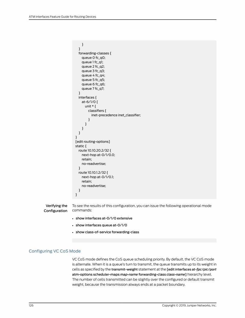
}}forwarding-classes {queue 0 fc_q0;queue 1 fc_q1;queue 2 fc_q2;queue 3 fc_q3;queue 4 fc_q4;queue 5 fc_q5;queue 6 fc_q6;queue 7 fc_q7;
}interfaces {at-6/1/0 {unit * {classifiers {inet-precedence inet_classifier;
}}
}}
}[edit routing-options]static {route 10.10.20.2/32 {next-hop at-0/1/0.0;retain;no-readvertise;
}route 10.10.1.2/32 {next-hop at-0/1/0.1;retain;no-readvertise;
}}
Verifying theConfiguration
To see the results of this configuration, you can issue the following operational modecommands:
• show interfaces at-0/1/0 extensive
• show interfaces queue at-0/1/0
• show class-of-service forwarding-class
Configuring VC CoSMode
VC CoSmode defines the CoS queue scheduling priority. By default, the VC CoSmode
is alternate. When it is a queue’s turn to transmit, the queue transmits up to its weight in
cells as specified by the transmit-weight statement at the [edit interfaces at-fpc/pic/port
atm-options scheduler-mapsmap-name forwarding-class class-name] hierarchy level.
The number of cells transmitted can be slightly over the configured or default transmit
weight, because the transmission always ends at a packet boundary.
Copyright © 2019, Juniper Networks, Inc.126
ATM Interfaces Feature Guide for Routing Devices
Toconfigure theVCCoSmode, include the vc-cos-mode statement at the [edit interfaces
at-fpc/pic/port atm-options scheduler-maps] hierarchy level:
edit interfaces at-fpc/pic/port atm-options scheduler-maps]vc-cos-mode (alternate | strict);
Twomodes of CoS scheduling priority are supported:
• alternate—Assign high priority to one queue. The scheduling of the queues alternates
between the high priority queue and the remaining queues. Every other scheduled
packet is from the high priority queue.
• strict—Assign strictly high priority to one queue. A queue with strictly high priority is
always scheduled before the remaining queues. The remaining queues are scheduled
in round-robin fashion.
Enabling the PLP Setting to Be Copied to the CLP Bit
For a PE router with customer edge (CE)-facing, egress, ATM2 IQ interfaces configured
with standard AAL5 encapsulation, you can enable the PLP setting to be copied into the
CLP bit.
NOTE: This configuration setting is not applicable to Layer 2 circuitencapsulations because the control word captures and preserves CLPinformation. For more information about Layer 2 circuit encapsulations, see“Configuring Layer 2 Circuit Transport Mode” on page 54.
By default, at egress ATM2 IQ interfaces configured with standard AAL5 encapsulation,
the PLP information is not copied to the CLP bit. This means the PLP information is not
carried beyond the egress interface onto the CE router.
You can enable the PLP information to be copied into the CLP bit by including the
plp-to-clp statement:
plp-to-clp;
You can include this statement at the following hierarchy levels:
• [edit interfaces interface-name atm-options]
• [edit interfaces interface-name unit logical-unit-number]
• [edit logical-systems logical-system-name interfaces interface-name unit
logical-unit-number]
Configuring ATMCoS on the Logical Interface
To apply the ATM scheduler map to a logical interface, include the atm-scheduler-map
statement:
127Copyright © 2019, Juniper Networks, Inc.
Chapter 2: Configuring ATM Interfaces

atm-scheduler-map (map-name | default);
For ATM CoS to take effect, youmust configure the VCI and VPI identifiers and traffic
shaping on each VC by including the following statements:
vci vpi-identifier.vci-identifier;shaping {(cbr rate | rtvbr peak rate sustained rate burst length | vbr peak rate sustained rate burstlength);
}
You can include these statements at the following hierarchy levels:
• [edit interfaces interface-name unit logical-unit-number]
• [edit logical-systems logical-system-name interfaces interface-name unit
logical-unit-number]
For more information, see “Configuring a Point-to-Point ATM1 or ATM2 IQ Connection”
on page 115 and “Defining the ATM Traffic-Shaping Profile Overview” on page 107.
You can also apply a scheduler map to the chassis traffic that feeds the ATM interfaces.
For more information, see the Class of Service Feature Guide for Routers and EX9200
Switches.
Example: Configuring ATM2 IQ VC Tunnel CoS Components
Configure ATM2 IQ VC tunnel CoS components:
[edit interfaces]at-1/2/0 {atm-options {vpi 0;linear-red-profiles red-profile-1 {queue-depth 35000 high-plp-threshold 75 low-plp-threshold 25;
}scheduler-mapsmap-1 {vc-cos-mode strict;forwarding-class best-effort {priority low;transmit-weight percent 25;linear-red-profile red-profile-1;
}}
}unit 0 {vci 0.128;shaping {vbr peak 20m sustained 10m burst 20;
}atm-scheduler-mapmap-1;family inet {address 192.168.0.100/32 {destination 192.168.0.101;
Copyright © 2019, Juniper Networks, Inc.128
ATM Interfaces Feature Guide for Routing Devices

}}
}}
See Also Configuring a Point-to-Point ATM1 or ATM2 IQ Connection on page 115•
• Defining the ATM Traffic-Shaping Profile Overview on page 107
• atm-scheduler-map on page 242
• vci on page 330
Configuring ATMScheduler on Ethernet VPLS over a Bridged ATM Interface
OnM7i routers, M10i routers with Enhanced III FPCs, and M320 routers with Enhanced III
FPCs, you can attach scheduler maps under ATM logical interfaces configured with
Ethernet VPLS over ATM (bridging) encapsulation.
The following configuration tasks are required:
• Define thescheduler-mapsstatementat the [edit interfacesat-fpc/pic/portatm-options]
hierarchy level, as follows:
[edit interfaces at-fpc/pic/port atm-options]
scheduler-mapsmap-name {forwarding-class (class-name | assured-forwarding | best-effortexpedited-forwarding | network-control);vc-cos-mode strict;
}
• Include the encapsulation ether-vpls-over-atm-llc statement at the [edit interfaces
at-fpc/pic/port unit logical-unit-number] hierarchy level, as follows:
[edit interfaces at-fpc/pic/port unit logical-unit-number]
encapsulation ether-vpls-over-atm-llc;
• Include the atm-scheduler-map at the [edit interfaces at-fpc/pic/port unit
logical-unit-number] hierarchy level, as follows.
[edit interfaces at-fpc/pic/port unit logical-unit-number]
atm-scheduler-map (map-name | default);
The scheduler map configured on the ATM device can be checked by using the PFE
command show atm slot number vpc on the FPC console
129Copyright © 2019, Juniper Networks, Inc.
Chapter 2: Configuring ATM Interfaces

RelatedDocumentation
encapsulation on page 255•
• Example: Configuring ATM Scheduler Map on Ethernet VPLS over Bridged ATM
Interfaces on page 130
Example: Configuring ATMScheduler Map on Ethernet VPLS over Bridged ATMInterfaces
This example describes sending packets between routers with ATM2 IQ interfaces using
Ethernet VPLS over ATM encapsulation.
interfaces {at-1/2/3 {atm-options {vpi 0;scheduler-maps {cos-vpls {forwarding-class assured-forwarding {priority low;transmit-weight percent 10;
}forwarding-class best-effort {priority low;transmit-weight percent 20;
}forwarding-class expedited-forwarding {priority low;transmit-weight percent 30;
}forwarding-class network-control {priority high;transmit-weight percent 40;
}}unit 0 {encapsulation ether-vpls-over-atm-llc;vci 0.100;family vpls;
}atm-scheduler-map cos-vpls;
}}
For a proper routing setup, a routing-instance for the VPLSmust be setup as well:
routing-instance {cos-test-v1 {instance-type vpls;interface at-1/2/3.0;route-distinguisher 10.10.10.1:1;vrf-target target:11111:1;protocols {vpls {
Copyright © 2019, Juniper Networks, Inc.130
ATM Interfaces Feature Guide for Routing Devices

site-range 10;site cos-test-v1-site1 {site-identifier 1;
}}
}}
}
RelatedDocumentation
encapsulation on page 255•
• ConfiguringATMScheduleronEthernetVPLSoveraBridgedATMInterfaceonpage 129
Configuring the ATM2 IQ EPD Threshold
The EPD threshold is a limit on the number of transmit cells that can be queued. Cells
that exceed the limit are discarded. When a beginning of packet (BOP) cell is received,
the VC’s queue depth is checked against the EPD threshold. If the VC’s queue depth
exceeds the EPD threshold, the BOP cell and all subsequent cells in the packet are
discarded. This prevents a single queue from draining all the buffers on the PIC.
By default, for UBR the EPD threshold is approximately 1 percent of the available cell
buffers. If shaping is enabled, the default EPD threshold is proportional to the shaping
rate according to the following formula:
default epd-threshold = number of buffers * shaping rate / line rate
By default, the software estimates howmuch buffer space is needed for each PVC.
However, you can configure the per-VC buffer space. In general, ATM PVCs need larger
buffers for data traffic and smaller buffers for time-sensitive applications. Unnecessarily
deep buffers might cause excessive delays on congested PVCs. Overly shallow buffers
might cause premature random early detection (RED) or tail packet drops in bursty
conditions.
TheminimumEPDthresholdvalue is48cells. If thedefault EPDthreshold formula results
in an EPD threshold of less than 48 cells, the result will be ignored, and theminimum
value of 48 cells will be used.
To set the EPD threshold of a PVC, include the epd-threshold statement:
epd-threshold cells;
For a list of hierarchy levels at which you can include this statement, see epd-threshold.
The allowable range for EPD threshold varies by interface type, as shown in
Table 14 on page 132.
131Copyright © 2019, Juniper Networks, Inc.
Chapter 2: Configuring ATM Interfaces

Table 14: EPD Threshold Range by Interface Type
EPD RangeInterface Type
48 through 425,984 cells1-port OC48
48 through 425,984 cells1-port and 2-port OC12
48 through 212,992 cells2-port OC3, DS3, and E3
48 through 106,496 cells4-port DS3 and E3
You should include the epd-threshold statement in the configuration of all the PVCs that
you configure on an ATM2 IQ PIC. The epd-threshold statement performs two functions:
• It prevents head-of-lineblockingbecause it limits thenumber of packets and therefore
buffers that can be consumed by each configured PVC.
• It sets the maximum lifetime that can be sustained by packets over the PVCwhen
traffic has oversubscribed the configured shaping contract.
If you add or change the EPD threshold on the VC, the logical interface associated with
the VC is deleted and re-added.
On ATM2 IQ DS3 and E3 interfaces, youmight be able to enter an EPD threshold or
shaping parameter that exceeds the maximum threshold for these interfaces. If the
configuration commits, the physical interface might indicate that it is up, but the logical
interface fails. As a workaround, configure shaping parameters and EPD thresholds that
do not exceed the bandwidth of the interface.
For information about configuring dual EPD thresholds on interfaces configured to use
Layer 2 circuit trunkmode, see “ConfiguringTwoEPDThresholdsperQueue” onpage 133.
• Example:Configuring theEPDThreshold foraPoint-to-pointATM2 Interfaceonpage 132
• Example: Configuring the EPD Threshold for a Point-to-multipoint ATM2
Interface on page 132
Example: Configuring the EPD Threshold for a Point-to-point ATM2 Interface
To configure the EPD threshold for a point-to-point ATM2 interface:
On a Point-to-PointATM2 Interface
[edit interfaces at-1/0/0]unit 0 {vci 0.123;epd-threshold 1300;...
}
Example: Configuring the EPD Threshold for a Point-to-multipoint ATM2 Interface
To configure the EPD threshold for a point-to-multipoint ATM2 interface:
Copyright © 2019, Juniper Networks, Inc.132
ATM Interfaces Feature Guide for Routing Devices
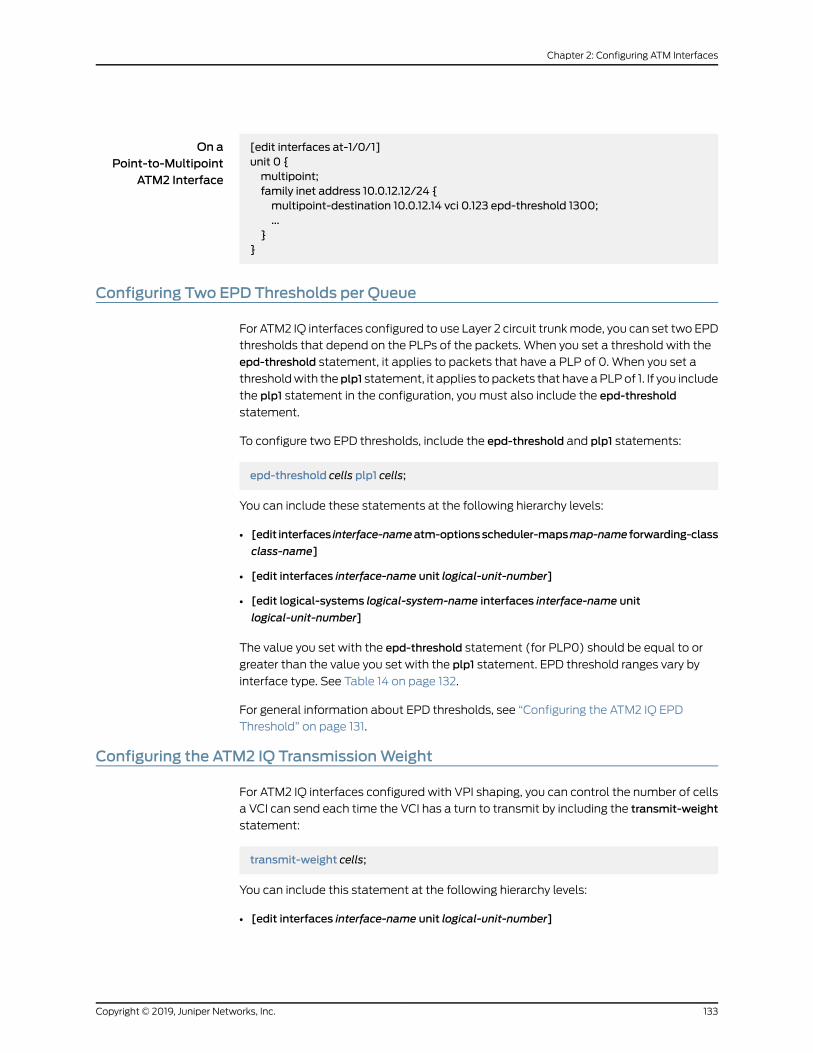
On aPoint-to-Multipoint
ATM2 Interface
[edit interfaces at-1/0/1]unit 0 {multipoint;family inet address 10.0.12.12/24 {multipoint-destination 10.0.12.14 vci 0.123 epd-threshold 1300;...
}}
Configuring Two EPD Thresholds per Queue
For ATM2 IQ interfaces configured to use Layer 2 circuit trunkmode, you can set two EPD
thresholds that depend on the PLPs of the packets. When you set a threshold with the
epd-threshold statement, it applies to packets that have a PLP of 0. When you set a
thresholdwith theplp1 statement, it applies to packets that have aPLPof 1. If you include
the plp1 statement in the configuration, youmust also include the epd-threshold
statement.
To configure two EPD thresholds, include the epd-threshold and plp1 statements:
epd-threshold cells plp1 cells;
You can include these statements at the following hierarchy levels:
• [edit interfaces interface-nameatm-optionsscheduler-mapsmap-name forwarding-class
class-name]
• [edit interfaces interface-name unit logical-unit-number]
• [edit logical-systems logical-system-name interfaces interface-name unit
logical-unit-number]
The value you set with the epd-threshold statement (for PLP0) should be equal to or
greater than the value you set with the plp1 statement. EPD threshold ranges vary by
interface type. See Table 14 on page 132.
For general information about EPD thresholds, see “Configuring the ATM2 IQ EPD
Threshold” on page 131.
Configuring the ATM2 IQ TransmissionWeight
For ATM2 IQ interfaces configured with VPI shaping, you can control the number of cells
a VCI can send each time the VCI has a turn to transmit by including the transmit-weight
statement:
transmit-weight cells;
You can include this statement at the following hierarchy levels:
• [edit interfaces interface-name unit logical-unit-number]
133Copyright © 2019, Juniper Networks, Inc.
Chapter 2: Configuring ATM Interfaces

• [edit logical-systems logical-system-name interfaces interface-name unit
logical-unit-number]
VPI traffic shaping is not supported on point-to-multipoint interfaces.
The number of cells can be from 1 through 32,000. For a configuration example, see
“Example: Configuring ATM2 IQ Interfaces” on page 38.
Configuring the JunosOS toEnableATM2 IntelligentQueuing Layer 2Circuit TransportMode
On ATM2 IQ PICs only, you can configure Layer 2 circuit cell relay, Layer 2 circuit ATM
Adaptation Layer 5 (AAL5), or Layer 2 circuit trunk mode.
Layer 2 circuit cell relay and Layer 2 circuit AAL5 are defined in the Internet draft
draft-martini-l2circuit-encap-mpls-04.txt, Encapsulation Methods for Transport of Layer
2 Frames Over IP and MPLS Networks.
Layer 2circuit trunkmodeallowsyou tosendATMcellsoverMultiprotocol LabelSwitching
(MPLS) trunking.
The four transport modes are defined as follows:
• To tunnel IP packets over an ATM backbone, use the default standard AAL5 transport
mode.
• To tunnel a stream of AAL5-encoded ATM segmentation-and-reassembly protocol
dataunits (SAR-PDUs)overanMPLSor IPbackbone, useLayer 2circuitAAL5 transport
mode.
• To tunnel a stream of ATM cells over an MPLS or IP backbone, use Layer 2 circuit
cell-relay transport mode.
• To transport ATM cells over anMPLS core network that is implemented on some other
vendor switches, use Layer 2 circuit trunk mode.
NOTE: You can transport AAL5-encoded traffic with Layer 2 circuitcell-relay transportmode,becauseLayer2circuit cell-relay transportmodeignores the encoding of the cell data presented to the ingress interface.
When you configure AAL5mode Layer 2 circuits, the control word carries cell loss priority
(CLP) information by default.
By default, ATM2 IQ PICs are in standard AAL5 transport mode. Standard AAL5 allows
multiple applications to tunnel the protocol data units of their Layer 2 protocols over an
ATM virtual circuit. To configure the Layer 2 circuit transport modes, include the
atm-l2circuit-modestatementat the [editchassis fpcslot-numberpicpic-number]hierarchy
level:
[edit chassis fpc slot-number pic pic-number]atm-l2circuit-mode (cell | aal5 | trunk trunk);
Copyright © 2019, Juniper Networks, Inc.134
ATM Interfaces Feature Guide for Routing Devices

On a TXMatrix or TXMatrix Plus router, include the atm-l2circuit-mode statement at the
[edit chassis lcc number fpc slot-number pic pic-number] hierarchy level:
[edit chassis lcc number fpc slot-number pic pic-number]atm-l2circuit-mode (cell | aal5 | trunk trunk);
aal5 tunnels a stream of AAL5-encoded ATM cells over an IP backbone.
cell tunnels a stream of ATM cells over an IP backbone.
trunk transports ATM cells over an MPLS core network that is implemented on some
other vendor switches. Trunk mode can be user-to-network interface (UNI) or
network-to-network interface (NNI).
NOTE: To determine which vendors support Layer 2 circuit trunkmode,contact Juniper Networks customer support.
RelatedDocumentation
Configuring the Junos OS to Support ILMI for Cell Relay Encapsulation on an ATM2 IQ
PIC on page 137
•
• Configuring the Junos OS to Enable Idle Cell Format and Payload Patterns for ATM
Devices on page 135
• Configuring the Junos OS to Use ATM Cell-Relay Accumulation Mode on an ATM1 PIC
on page 136
Configuring the Junos OS to Enable Idle Cell Format and Payload Patterns for ATMDevices
ATM devices send idle cells to enable the receiving ATM interface to recognize the start
of each new cell. The receiving ATM device does not act on the contents of idle cells and
does not pass them up to the ATM layer in the ATM protocol stack.
By default, the idle cell format for ATM cells is (4 bytes): 0x00000000. For ATM 2 PICs
and ATMMICs, you can configure the format of the idle cell header and payload bytes.
To configure the idle cell header to use the International Telecommunications Union
(ITU-T) standard of 0x00000001, include the itu-t statement at the [edit chassis fpc
slot-number pic number idle-cell-format] hierarchy level:
[edit chassis fpc slot-number pic pic-number idle-cell-format]itu-t;
On a TXMatrix or TX Matrix Plus router, include the itu-t statement at the [edit chassis
lcc number fpc slot-number pic pic-number idle-cell-format] hierarchy level:
[edit chassis lcc number fpc slot-number pic pic-number idle-cell-format]itu-t;
135Copyright © 2019, Juniper Networks, Inc.
Chapter 2: Configuring ATM Interfaces

By default, the payload pattern is cell payload (48 bytes). To configure the idle cell
payloadpattern, include thepayload-patternstatementat the [editchassis fpcslot-number
pic pic-number idle-cell-format] hierarchy level:
[edit chassis fpc slot-number pic pic-number idle-cell-format]payload-pattern payload-pattern-byte;
On a TXMatrix router, include the payload-pattern statement at the [edit chassis lcc
number fpc slot-number pic pic-number idle-cell-format] hierarchy level:
[edit chassis lcc number fpc slot-number pic pic-number idle-cell-format]payload-pattern payload-pattern-byte;
The payload pattern byte can range from 0x00 through 0xff.
For information about the TXMatrix router, see TXMatrix Router and T640 Router
Configuration Overview. For information about the TXMatrix Plus router, see TXMatrix
Plus Router Configuration Overview.
RelatedDocumentation
Configuring the Junos OS to Use ATM Cell-Relay Accumulation Mode on an ATM1 PIC
on page 136
•
• Configuring the JunosOS to Enable ATM2 Intelligent Queuing Layer 2 Circuit Transport
Mode on page 134
• Configuring the Junos OS to Support ILMI for Cell Relay Encapsulation on an ATM2 IQ
PIC on page 137
• Configuring Layer 2 Circuit Transport Mode on ATMMICs on page 64
• Example: Configuring Layer 2 Circuit Transport Mode on ATMMICs on page 65
Configuring the Junos OS to Use ATMCell-Relay AccumulationMode on an ATM1 PIC
You can configure an Asynchronous Transfer Mode (ATM) 1 PIC to use cell-relay
accumulation mode. In this mode, the incoming cells (one to eight cells) are packaged
into a single packet and forwarded to the label-switched path (LSP). At the edge router,
this packet is divided in to individual cells and transmitted over the ATM interface.
NOTE: When you configure an ATM PIC to use cell-relay accumulation, allports on the ATM PIC use cell-relay accumulationmode.
To configure an ATM PIC to use cell-relay accumulation mode, include the
atm-cell-relay-accumulation statementat the [editchassis fpcslot-numberpicpic-number]
hierarchy level:
[edit chassis fpc slot-number pic pic-number ]atm-cell-relay-accumulation;
Copyright © 2019, Juniper Networks, Inc.136
ATM Interfaces Feature Guide for Routing Devices

OnaTXMatrixorTXMatrixPlus router, include theatm-cell-relay-accumulationstatement
at the [edit chassis lcc number fpc slot-number pic pic-number] hierarchy level:
[edit chassis lcc number fpc slot-number pic pic-number]atm-cell-relay-accumulation;
RelatedDocumentation
Configuring the JunosOS to Enable ATM2 Intelligent Queuing Layer 2 Circuit Transport
Mode on page 134
•
• Configuring the Junos OS to Support ILMI for Cell Relay Encapsulation on an ATM2 IQ
PIC on page 137
• Configuring the Junos OS to Enable Idle Cell Format and Payload Patterns for ATM
Devices on page 135
• atm-cell-relay-accumulation
Configuring the Junos OS to Support ILMI for Cell Relay Encapsulation on an ATM2 IQPIC
IntegratedLocalManagement Interface (ILMI) is supportedonAAL5 interfaces, regardless
of transport mode. To enable ILMI on interfaces with cell-relay encapsulation, youmust
configure an ATM2 IQ PIC to use Layer 2 circuit trunk transport mode.
To configure ILMI on an interface with cell-relay encapsulation, include the following
statements:
[edit chassis fpc slot-number pic pic-number]atm-l2circuit-mode trunk trunk;[edit interfaces at-fpc/pic/port]encapsulation atm-ccc-cell-relay;atm-options {ilmi;pic-type atm2;
}unit logical-unit-number {trunk-id number;
}
RelatedDocumentation
• Configuring the JunosOS to Enable ATM2 Intelligent Queuing Layer 2 Circuit Transport
Mode on page 134
137Copyright © 2019, Juniper Networks, Inc.
Chapter 2: Configuring ATM Interfaces

Copyright © 2019, Juniper Networks, Inc.138
ATM Interfaces Feature Guide for Routing Devices

CHAPTER 3
Configuring Passive Monitoring on ATMInterfaces
• Enabling Passive Monitoring on ATM Interfaces on page 139
• Removing MPLS Labels from Incoming Packets on page 140
Enabling Passive Monitoring on ATM Interfaces
TheMonitoringServices I andMonitoringServices II PICsaredesigned toenable IPservices.
If you have aMonitoring Services PIC and an ATMPIC installed in anMSeries, MX Series,
or T Series router, you canmonitor IPv4 and IPv6 traffic from another router.
On ATM interfaces, you enable packet flowmonitoring by including the
passive-monitor-mode statement at the [edit interfaces at-fpc/pic/port] hierarchy level:
[edit interfaces at-fpc/pic/port]passive-monitor-mode;
If you include thepassive-monitor-mode statement in theconfiguration, theATM interface
is always up, and the interface does not receive or transmit incoming control packets,
such as OAM cell and ILMI.
Onmonitoring services interfaces, you enable packet flowmonitoring by including the
family statementat the [edit interfacesmo-fpc/pic/portunit logical-unit-number]hierarchy
level, specifying the inet option:
[edit interfacesmo-fpc/pic/port unit logical-unit-number]family inet;
For conformitywith cflowd record structure, youmust include the receive-options-packets
and receive-ttl-exceeded statements at the [edit interfacesmo-fpc/pic/port unit
logical-unit-number family inet] hierarchy level:
[edit interfacesmo-fpc/pic/port unit logical-unit-number family inet]receive-options-packets;receive-ttl-exceeded;
139Copyright © 2019, Juniper Networks, Inc.
RelatedDocumentation
Configuring Multiservice Physical Interface Properties•
RemovingMPLS Labels from Incoming Packets
The Junos OS can forward only IPv4 packets to a Monitoring Services PIC. IPv4 packets
withMPLS labels cannotbe forwarded toaMonitoringServicesPIC. Bydefault, if packets
with MPLS labels are forwarded to the Monitoring Services PIC, they are discarded. To
monitor packets with MPLS labels, youmust remove the MPLS labels as the packets
arrive on the interface.
You can remove up to twoMPLS labels from an incoming packet by including the
pop-all-labelsstatementat the [edit interfaces interface-nameatm-optionsmpls]hierarchy
level:
[edit interfaces interface-name atm-optionsmpls]pop-all-labels {required-depth number;
}
NOTE: On T Series devices, the pop-all-labels command can remove up to
five MPLS labels from incoming packets.
By default, the pop-all-labels statement takes effect for incoming packets with one or
two labels. You can specify the number of MPLS labels an incoming packet must have
for the pop-all-labels statement to take effect by including the required-depth statement
at the [edit interfaces interface-name atm-optionsmpls pop-all-labels] hierarchy level:
[edit interfaces interface-name atm-optionsmpls pop-all-labels]required-depth number;
The required depth can be 1, 2, or [ 1 2 ]. If you include the required-depth 1 statement, the
pop-all-labels statement takes effect for incoming packets with one label only. If you
include the required-depth 2 statement, the pop-all-labels statement takes effect for
incoming packetswith two labels only. If you include the required-depth [ 1 2 ] statement,
the pop-all-labels statement takes effect for incoming packets with one or two labels.
A required depth of [ 1 2 ] is equivalent to the default behavior of the pop-all-labels
statement.
When you remove MPLS labels from incoming packets, note the following:
• The pop-all-labels statement has no effect on IP packets with three or more MPLS
labels.
• When you enable MPLS label removal, you must configure all ports on a PIC with the
same label popping mode and required depth.
• You use the pop-all-labels statement to enable passive monitoring applications, not
active monitoring.
Copyright © 2019, Juniper Networks, Inc.140
ATM Interfaces Feature Guide for Routing Devices

• You cannot apply MPLS filters or accounting to the MPLS labels because the labels
are removed as soon as the packet arrives on the interface.
• The following ATM encapsulation types are not supported on interfaces with MPLS
label removal:
• atm-ccc-cell-relay
• atm-ccc-vc-mux
• atm-mlppp-llc
• atm-tcc-snap
• atm-tcc-vc-mux
• ether-over-atm-llc
• ether-vpls-over-atm-llc
RelatedDocumentation
• atm-options on page 241
• mpls on page 288
• pop-all-labels on page 300
• required-depth on page 308
141Copyright © 2019, Juniper Networks, Inc.
Chapter 3: Configuring Passive Monitoring on ATM Interfaces

Copyright © 2019, Juniper Networks, Inc.142
ATM Interfaces Feature Guide for Routing Devices

PART 2
ATM-over-ADSL Interfaces
• ATM-over-ADSL Interfaces Overview on page 145
• Configuring ATM-over-ADSL Interfaces on page 147
143Copyright © 2019, Juniper Networks, Inc.

Copyright © 2019, Juniper Networks, Inc.144
ATM Interfaces Feature Guide for Routing Devices
CHAPTER 4
ATM-over-ADSL Interfaces Overview
• ATM-over-ADSL Overview on page 145
ATM-over-ADSL Overview
You configure the underlying ADSL as an ATM interface with an interface name of
at-pim/0/port. Multiple encapsulation types are supported on both the physical and
logical ATM-over-ADSL interface.
You can configure Point-to-Point Protocol over Ethernet (PPPoE) over ATM to connect
through DSL lines. For PPPoE on an ATM-over-ADSL interface, youmust configure
encapsulation on both the physical and logical interfaces. To configure encapsulation
on an ATM-over-ADSL physical interface, use Ethernet over ATM encapsulation. To
configure encapsulation on an ATM-over-ADSL logical interface, use the PPPoE over
AAL5 LLC encapsulation. LLC encapsulation allows a single ATM virtual connection to
transport multiple protocols.
NOTE: PPPoE encapsulation is not supported on anM120 router with ATM2PICs.
When you configure a point-to-point encapsulation such as PPP on a physical interface,
the physical interface can have only one logical interface (only one unit statement)
associated with it.
For more information about configuring PPPoE, see Configuring PPPoE.
RelatedDocumentation
• Configuring the ATM-over-ADSL Virtual Path Identifier on page 148
• Configuring the ATM-over-ADSL Physical Interface Operating Mode on page 148
• Configuring the ATM-over-ADSL Physical Interface Encapsulation Type on page 149
• Configuring the ATM-over-ADSL Logical Interface Encapsulation Type on page 150
• Configuring the ATM-over-ADSL Protocol Family on page 151
• Configuring the ATM-over-ADSL Virtual Channel Identifier on page 151
145Copyright © 2019, Juniper Networks, Inc.

Copyright © 2019, Juniper Networks, Inc.146
ATM Interfaces Feature Guide for Routing Devices

CHAPTER 5
Configuring ATM-over-ADSL Interfaces
• Configuring Physical ATM Interfaces and Logical Interface Properties for
ADSL on page 147
• Configuring the ATM-over-ADSL Virtual Path Identifier on page 148
• Configuring the ATM-over-ADSL Physical Interface Operating Mode on page 148
• Configuring the ATM-over-ADSL Physical Interface Encapsulation Type on page 149
• Configuring the ATM-over-ADSL Logical Interface Encapsulation Type on page 150
• Configuring the ATM-over-ADSL Protocol Family on page 151
• Configuring the ATM-over-ADSL Virtual Channel Identifier on page 151
Configuring Physical ATM Interfaces and Logical Interface Properties for ADSL
To configure physical ATM interfaces for ADSL, include the vpi 0 statement at the [edit
interfaces at-pim/0/port atm-options] hierarchy level, the operating-mode statement at
the [edit interfaces at-pim/0/port dsl-options] hierarchy level, and the encapsulation
statement at the [edit interfaces at-pim/0/port] hierarchy level:
[edit interfaces at-pim/0/port]atm-options {vpi 0;
}dsl-options {operating-modemode;
}encapsulation (atm-pvc | ethernet-over-atm);
Configure logical interface properties by including the encapsulation statement, family
statement, and vci statement:
unit logical-unit-number {encapsulation(atm-vc-mux |atm-nlpd |atm-cisco-nlpd |atm-snap |atm-ppp-vc-mux |atm-ppp-llc | ether-over-atm-llc | ppp-over-ether-over-atm-llc);
family inet {vci vpi-identifier.vci-identifier;
}}
You can include these statements at the following hierarchy levels:
147Copyright © 2019, Juniper Networks, Inc.
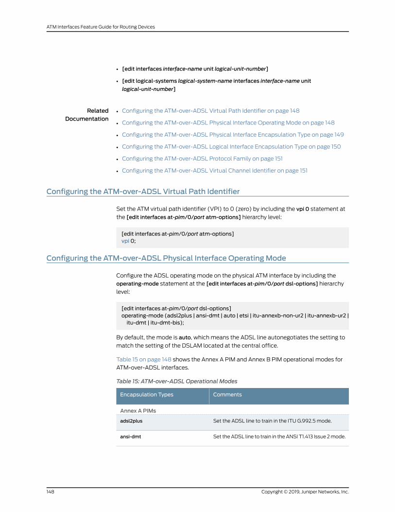
• [edit interfaces interface-name unit logical-unit-number]
• [edit logical-systems logical-system-name interfaces interface-name unit
logical-unit-number]
RelatedDocumentation
Configuring the ATM-over-ADSL Virtual Path Identifier on page 148•
• Configuring the ATM-over-ADSL Physical Interface Operating Mode on page 148
• Configuring the ATM-over-ADSL Physical Interface Encapsulation Type on page 149
• Configuring the ATM-over-ADSL Logical Interface Encapsulation Type on page 150
• Configuring the ATM-over-ADSL Protocol Family on page 151
• Configuring the ATM-over-ADSL Virtual Channel Identifier on page 151
Configuring the ATM-over-ADSL Virtual Path Identifier
Set the ATM virtual path identifier (VPI) to 0 (zero) by including the vpi 0 statement at
the [edit interfaces at-pim/0/port atm-options] hierarchy level:
[edit interfaces at-pim/0/port atm-options]vpi 0;
Configuring the ATM-over-ADSL Physical Interface OperatingMode
Configure the ADSL operating mode on the physical ATM interface by including the
operating-mode statement at the [edit interfaces at-pim/0/port dsl-options] hierarchy
level:
[edit interfaces at-pim/0/port dsl-options]operating-mode (adsl2plus | ansi-dmt | auto | etsi | itu-annexb-non-ur2 | itu-annexb-ur2 |itu-dmt | itu-dmt-bis);
By default, the mode is auto, which means the ADSL line autonegotiates the setting to
match the setting of the DSLAM located at the central office.
Table 15 on page 148 shows the Annex A PIM and Annex B PIM operational modes for
ATM-over-ADSL interfaces.
Table 15: ATM-over-ADSL Operational Modes
CommentsEncapsulation Types
Annex A PIMs
Set the ADSL line to train in the ITU G.992.5 mode.adsl2plus
Set theADSL line to train in theANSI T1.413 Issue 2mode.ansi-dmt
Copyright © 2019, Juniper Networks, Inc.148
ATM Interfaces Feature Guide for Routing Devices

Table 15: ATM-over-ADSL Operational Modes (continued)
CommentsEncapsulation Types
Set the ADSL line to autonegotiate the setting to matchthe setting of the DSLAM located at the central office.
The ADSL line trains in the ANSI T1.413 Issue 2 (ansi-dmt)or ITU G.992.1 (itu-dmt) mode.
auto
Set the ADSL line to train in the ITU G.992.1 mode.itu-dmt
Set the ADSL line to train in the ITU G.992.3 mode.itu-dmt-bis
Set the ADSL line to train in the G.992.2 mode.itu-lite
Set the ADSL line to train in the G.992.4 mode.itu-lite-bis
Annex B PIMs
Set the ADSL line to train in the ITU G.992.5 mode.adsl2plus
Set the ADSL line after autonegotiating the setting tomatch the setting of the DSLAM located at the centraloffice.
auto
Set the ADSL line to train in the ETSI TS 101 388 V1.3.1mode.
etsi
Set the ADSL line to train in the ITU G.992.1 mode.itu-dmt
Set the ADSL line to train in the ITU G.992.3 mode.itu-dmt-bis
Set the ADSL line to train in the ITU G.992.1 DeutscheTelekom UR-2mode.
itu-annexb-ur2
Set the ADSL line to train in the ITU G.992.1 non-UR-2mode.
itu-annexb-non-ur2
Set the ADSL line to train in the ITU G.992.1 mode.itu-dmt
Configuring the ATM-over-ADSL Physical Interface Encapsulation Type
Configure the physical interface encapsulation type by including the encapsulation
statement at the [edit interfaces at-pim/0/port] hierarchy level:
[edit interfaces at-pim/0/port]encapsulation type;
Table 16onpage 150showsthephysical interfaceencapsulation types forATM-over-ADSL
interfaces.
149Copyright © 2019, Juniper Networks, Inc.
Chapter 5: Configuring ATM-over-ADSL Interfaces

Configuring the ATM-over-ADSL Logical Interface Encapsulation Type
Configure the logical interface encapsulation type by including the encapsulation
statement:
[edit interfaces at-pim/0/port unit logical-unit-number]encapsulation type;
You can include this statement at the following hierarchy levels:
[edit interfaces interface-name unit logical-unit-number]
[edit logical-systems logical-system-name interfaces interface-name unit
logical-unit-number]
Table 16onpage 150shows the logical interfaceencapsulation types forATM-over-ADSL
interfaces.
Table 16: ATM-over-ADSL Encapsulation Types
CommentsEncapsulation Types
Physical Interface
Ethernet over ATM encapsulation.
Use this type of encapsulation for interfaces that carryIPv4 traffic.
ether-over-atm
ATM permanent virtual circuits (PVCs).atm-pvc
Logical Interface
Use ATM VCmultiplex encapsulation.
You can only configure the inet family when you use thistype of encapsulation.
atm-vc-mux
UseATMnetwork layerprotocol ID (NLPD)encapsulation.
You can only configure the inet family when you use thistype of encapsulation.
atm-nlpd
Use Cisco NLPD encapsulation.
You can only configure the inet family when you use thistype of encapsulation.
atm-cisco-nlpd
Use ATM subnetwork attachment point (SNAP)encapsulation.
atm-snap
Use PPP over ATM AAL5multiplex encapsulation.atm-ppp-vc-mux
Use ATM PPP over AAL5 logical link control (LLC)encapsulation.
atm-ppp-llc
Copyright © 2019, Juniper Networks, Inc.150
ATM Interfaces Feature Guide for Routing Devices
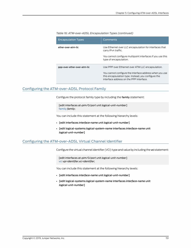
Table 16: ATM-over-ADSL Encapsulation Types (continued)
CommentsEncapsulation Types
Use Ethernet over LLC encapsulation for interfaces thatcarry IPv4 traffic.
You cannot configuremultipoint interfaces if you use thistype of encapsulation.
ether-over-atm-llc
Use PPP over Ethernet over ATM LLC encapsulation.
You cannot configure the interface addresswhen you usethis encapsulation type. Instead, you configure theinterface address on the PPP interface.
ppp-over-ether-over-atm-llc
Configuring the ATM-over-ADSL Protocol Family
Configure the protocol family type by including the family statement:
[edit interfaces at-pim/0/port unit logical-unit-number]family family;
You can include this statement at the following hierarchy levels:
• [edit interfaces interface-name unit logical-unit-number]
• [edit logical-systems logical-system-name interfaces interface-name unit
logical-unit-number]
Configuring the ATM-over-ADSL Virtual Channel Identifier
Configure thevirtual channel identifier (VCI) typeandvalueby including thevci statement:
[edit interfaces at-pim/0/port unit logical-unit-number]vci vpi-identifier.vci-identifier;
You can include this statement at the following hierarchy levels:
• [edit interfaces interface-name unit logical-unit-number]
• [edit logical-systems logical-system-name interfaces interface-name unit
logical-unit-number]
151Copyright © 2019, Juniper Networks, Inc.
Chapter 5: Configuring ATM-over-ADSL Interfaces

Copyright © 2019, Juniper Networks, Inc.152
ATM Interfaces Feature Guide for Routing Devices

PART 3
ATM-over-SHDSL Interfaces
• Configuring ATM-over-SHDSL Interfaces on page 155
153Copyright © 2019, Juniper Networks, Inc.

Copyright © 2019, Juniper Networks, Inc.154
ATM Interfaces Feature Guide for Routing Devices

CHAPTER 6
Configuring ATM-over-SHDSL Interfaces
• Configuring ATMMode for SHDSL Overview on page 155
• Configuring ATMMode on the PIM on page 157
• Configuring SHDSL Operating Mode on an ATM Physical Interface on page 157
• Configuring Encapsulation on the ATM Physical Interface on page 158
• Configuring Logical Interface Properties on page 158
• Example: Configuring an ATM-over-SHDSL Interface on page 160
• Verifying an ATM-over-SHDSL Interface Configuration on page 161
Configuring ATMMode for SHDSLOverview
To configure the ATMmode for SHDSL, include the pic-mode statement at the [edit
chassis fpc fpc-number pic 0 shdsl] hierarchy level:
[edit chassis]fpc fpc-number {pic 0 {shdsl {pic-mode (1-port-atm | 2-port-atm);
}}
}
For more information about configuring the ATMmode, see the Junos OS Administration
Library and the Junos OS Interfaces and Routing Configuration Guide.
To configure SHDSL operating mode on the physical ATM interface and set the
encapsulation, include the shdsl-options statement and the encapsulation statement at
the [edit interfaces at-pim/0/port] hierarchy level:
[edit interfaces at-pim/0/port]shdsl-options {annex (annex-a | annex-b);line-rate line-rate;loopback (local remote);snr-margin {snextmargin;
155Copyright © 2019, Juniper Networks, Inc.
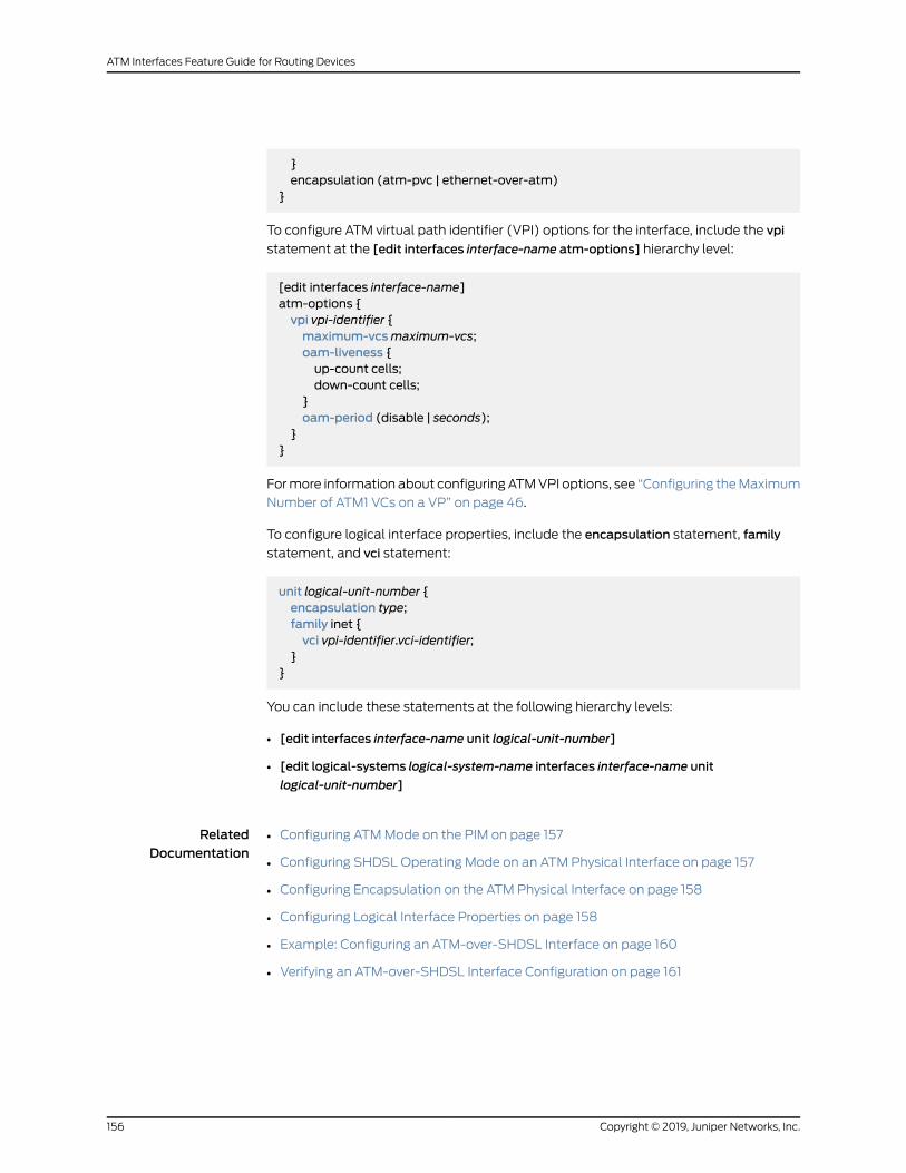
}encapsulation (atm-pvc | ethernet-over-atm)
}
To configure ATM virtual path identifier (VPI) options for the interface, include the vpi
statement at the [edit interfaces interface-name atm-options] hierarchy level:
[edit interfaces interface-name]atm-options {vpi vpi-identifier {maximum-vcsmaximum-vcs;oam-liveness {up-count cells;down-count cells;
}oam-period (disable | seconds);
}}
Formore information about configuring ATMVPI options, see “Configuring theMaximum
Number of ATM1 VCs on a VP” on page 46.
To configure logical interface properties, include the encapsulation statement, family
statement, and vci statement:
unit logical-unit-number {encapsulation type;family inet {vci vpi-identifier.vci-identifier;
}}
You can include these statements at the following hierarchy levels:
• [edit interfaces interface-name unit logical-unit-number]
• [edit logical-systems logical-system-name interfaces interface-name unit
logical-unit-number]
RelatedDocumentation
Configuring ATMMode on the PIM on page 157•
• Configuring SHDSL Operating Mode on an ATM Physical Interface on page 157
• Configuring Encapsulation on the ATM Physical Interface on page 158
• Configuring Logical Interface Properties on page 158
• Example: Configuring an ATM-over-SHDSL Interface on page 160
• Verifying an ATM-over-SHDSL Interface Configuration on page 161
Copyright © 2019, Juniper Networks, Inc.156
ATM Interfaces Feature Guide for Routing Devices

Configuring ATMMode on the PIM
You can configure only onemode on each 2-port SHDSL PIM.
The two-wiremode supports autodetection of the line rate or fixed line rate and network
speeds from 192 Kbps to 2.3 Kbps in 64-Kbps increments.
For informationabout configuringAnnexAorAnnexB, see “ConfiguringSHDSLOperating
Mode on an ATM Physical Interface” on page 157.
To configure the ATMmode for SHDSL, include the pic-mode statement at the [edit
chassis fpc fpc-number pic 0 shdsl] hierarchy level:
[edit chassis]fpc fpc-number {pic 0 {shdsl {pic-mode (1-port-atm | 2-port-atm);
}}
}
The default is 2-wire (two-port ATM)mode. To set the default explicitly, specify the
2-port-atm option. For 4-wire (single-port ATM)mode, specify the 1-port-atm option.
For more information about configuring the pic-mode statement, see the Junos OS
Administration Library. For information about configuring the ATMmode, see the Junos
OS Interfaces and Routing Configuration Guide.
Configuring SHDSLOperatingMode on an ATMPhysical Interface
To configure the SHDSL operating mode on the physical ATM interface, include the
shdsl-options statement at the [edit interfaces at-pim/0/port] hierarchy level:
[edit interfaces at-pim/0/port]shdsl-options {annex (annex-a | annex-b);line-rate line-rate;loopback (local | remote);snr-margin {snextmargin;
}}
Configure the following SHDSL options:
• annex—The type of annex:
• annex-a—Use for North American SHDSL network implementations.
157Copyright © 2019, Juniper Networks, Inc.
Chapter 6: Configuring ATM-over-SHDSL Interfaces

• annex-b—Use for European SHDSL network implementations.
• line-rate—The SHDSL line rate. The default for 2-wire mode is auto. The default for
4-wire mode is 4608 Kbps.
• loopback—A loopback connection, local or remote.
• local—Use to troubleshoot physical PIC errors. A local loopback loops packets,
including both data and timing information, back on the local router’s PIM.
• remote—Use to troubleshoot physical circuit problems between the local router and
the remote router. A remote loopback loops packets, including both data and timing
information, back on the remote router’s PIC.
• snr-margin—TheSHDSL signal-to-noise ratio (SNR)margin, currentor snext. TheSNR
margin is the difference between the desired SNR and the actual SNR.
• current—Current SNR is the difference between desired SNR and the actual SNR.
When configured, the line trains at higher than current noise margin plus SNR
threshold.
• snext—Self-near-end crosstalk (SNEXT) SNRmargin line trains the line at higher
than SNEXT threshold.
Configuring Encapsulation on the ATMPhysical Interface
To configure the type of encapsulation for the physical ATM interface, include the
encapsulation statement at the [edit interfaces at-pim /0/port] hierarchy level:
[edit interfaces at-pim/0/port]encapsulation (atm-pvc | ether-over-atm);
Configure one of the following:
• atm-pvc—ATM permanent virtual circuits (PVCs), used for PPP over ATM over SHDSL
interfaces. This is the default encapsulation.
• ether-over-atm—EthernetoverATMencapsulation. For interfaces that carry IPv4 traffic,
use this type of encapsulation.
RelatedDocumentation
Configuring ATM Interface Encapsulation on page 51•
• Example: Combining Layer 2 and Layer 3 Classification on the Same ATM Physical
Interface
Configuring Logical Interface Properties
To configure logical interface properties, include the encapsulation statement, family
statement, and vci statement:
unit logical-unit-number {
Copyright © 2019, Juniper Networks, Inc.158
ATM Interfaces Feature Guide for Routing Devices

encapsulation type;family inet {vci vpi-identifier.vci-identifier;
}}
You can include these statements at the following hierarchy levels:
• [edit interfaces interface-name unit logical-unit-number]
• [edit logical-systems logical-system-name interfaces interface-name unit
logical-unit-number]
Toconfigure the logical link-layerencapsulation type, include theencapsulationstatement.
ATM-over-SHDSL interfaces that use inet (IP) protocols support the following
encapsulations on the logical interface:
• atm-vc-mux—Use ATM VCmultiplex encapsulation. You can only configure the inet
family when you use this type of encapsulation.
• atm-nlpd—Use ATM network layer protocol ID (NLPD) encapsulation. You can only
configure the inet family when you use this type of encapsulation.
• atm-cisco-nlpd—UseCiscoNLPDencapsulation. You canonly configure the inet family
when you use this type of encapsulation.
ATM-over-SHDSL for PPP over ATM interfaces support the following encapsulations on
the logical interface:
• atm-ppp-llc—Use ATM PPP over AAL5 logical link control (LLC) encapsulation.
• atm-ppp-vc-mux—Use PPP over ATM AAL5multiplex encapsulation.
ATM-over-SHDSL interfaces also support the following encapsulations on the logical
interface:
• atm-snap—Use ATM subnetwork attachment point (SNAP) encapsulation.
• atm-mlppp-llc—For ATM2 IQ interfaces only, use Multilink PPP (MLPPP) over AAL5
LLC. For this encapsulation type, your router must be equipped with a Link Services or
VoiceServicesPIC.MLPPPoverATMencapsulation is not supportedonATM2 IQOC48
interfaces.
• ppp-over-ether-over-atm-llc—Use PPP over Ethernet over ATM LLC encapsulation.
When you use this encapsulation type, you cannot configure the interface address.
Instead, you configure the interface address on the PPP interface.
• family—The family protocol type.
• vci—The virtual channel identifier (VCI) type and value.
159Copyright © 2019, Juniper Networks, Inc.
Chapter 6: Configuring ATM-over-SHDSL Interfaces

• vci-identifier—ATM virtual circuit identifier. Unless you configure the interface to use
promiscuous mode, this value cannot exceed the largest numbered VC configured for
the interfacewith themaximum-vcsoptionof the vpi statement. Specify aVCI identifier
from 0 through 4089 or 0 through 65,535 with promiscuous mode. VCIs from
0 through 31 are reserved.
• vpi-identifier—ATMvirtual path identifier. Specify aVPI from0 through255. Thedefault
is 0.
RelatedDocumentation
unit on page 319•
• encapsulation on page 251
• family on page 265
• vci on page 330
Example: Configuring an ATM-over-SHDSL Interface
The following example illustrates an ATM-over-SHDSL interface configuration.
Configuration for theATMMode on the PIM
[edit chassis]fpc 6 {pic 0 {shdsl {pic-mode 2-port-atm;
}}
}
Configuration for theSHDSLOperating
[edit interfaces at-6/0/0/0]shdsl-options {
Mode on the PhysicalATM Interface
annex annex-b;line-rate 192;loopback local;snr-margin {current 1;snext 2;
}}
Configuration for theEncapsulation on thePhysicalATMInterface
[edit interfaces at-6/0/0/0]encapsulation ethernet-over-atm;
Configuration for theLogical Interface
[edit interfaces at-6/0/0/0 unit 3]encapsulation atm-nlpid;family inet {vci 25;
Copyright © 2019, Juniper Networks, Inc.160
ATM Interfaces Feature Guide for Routing Devices

}
RelatedDocumentation
Configuring ATMMode for SHDSL Overview on page 155•
• Verifying an ATM-over-SHDSL Interface Configuration on page 161
Verifying an ATM-over-SHDSL Interface Configuration
To verify an ATM-over-SHDSL interface configuration, you can issue the following
operational mode command:
user@host> show interfaces at-pim/0/port extensive
RelatedDocumentation
• Configuring ATMMode for SHDSL Overview on page 155
• Example: Configuring an ATM-over-SHDSL Interface on page 160
161Copyright © 2019, Juniper Networks, Inc.
Chapter 6: Configuring ATM-over-SHDSL Interfaces

Copyright © 2019, Juniper Networks, Inc.162
ATM Interfaces Feature Guide for Routing Devices

PART 4
Troubleshooting Information
• Monitoring and Troubleshooting ATM Interfaces on page 165
163Copyright © 2019, Juniper Networks, Inc.

Copyright © 2019, Juniper Networks, Inc.164
ATM Interfaces Feature Guide for Routing Devices
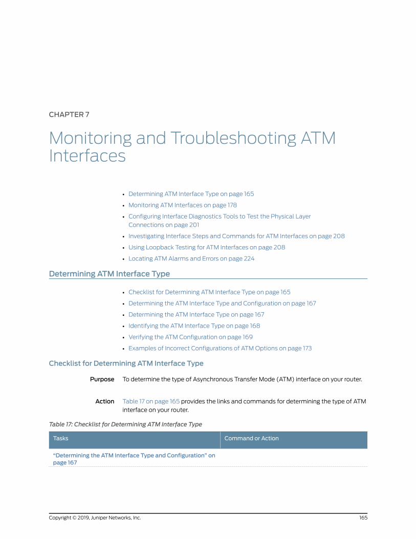
CHAPTER 7
Monitoring and Troubleshooting ATMInterfaces
• Determining ATM Interface Type on page 165
• Monitoring ATM Interfaces on page 178
• Configuring Interface Diagnostics Tools to Test the Physical Layer
Connections on page 201
• Investigating Interface Steps and Commands for ATM Interfaces on page 208
• Using Loopback Testing for ATM Interfaces on page 208
• Locating ATM Alarms and Errors on page 224
Determining ATM Interface Type
• Checklist for Determining ATM Interface Type on page 165
• Determining the ATM Interface Type and Configuration on page 167
• Determining the ATM Interface Type on page 167
• Identifying the ATM Interface Type on page 168
• Verifying the ATM Configuration on page 169
• Examples of Incorrect Configurations of ATMOptions on page 173
Checklist for Determining ATM Interface Type
Purpose To determine the type of Asynchronous Transfer Mode (ATM) interface on your router.
Action Table 17 on page 165 provides the links and commands for determining the type of ATM
interface on your router.
Table 17: Checklist for Determining ATM Interface Type
Command or ActionTasks
“Determining the ATM Interface Type and Configuration” onpage 167
165Copyright © 2019, Juniper Networks, Inc.

Table 17: Checklist for Determining ATM Interface Type (continued)
Command or ActionTasks
show chassis hardware
NOTE: For ATM1 and ATM2 interfaces.
1. Determining the ATM Interface Type on page 167
show chassis hardware
NOTE: For ATMMIC interfaces.
2. Identifying the ATM Interface Type on page 168
3. Verifying the ATM Configuration on page 169
show configuration interfaces at-fpc/pic/porta. Verifying the Configuration of an ATM1 Interface on page 170
show configuration interfaces at-fpc/pic/portb. Verifying the Configuration of an ATM2 IQ Interface onpage 171
show configuration interfaces at-fpc/pic/portc. Verifying the Configuration of an ATMMIC Interface onpage 172
“Examples of Incorrect Configurations of ATMOptions” onpage 173
show configuration interfaces at-fpc/pic/portshow interfaces terse at-fpc/pic/porteditedit interfaces interface-nameatm-optionsvpivpi-identifiermaximum-vcsmaximum-vcsshowcommitshow configuration interfaces at-fpc/pic/portrun show interfaces terse at-fpc/pic/port
1. Verifying the Configuration of the VCI on an ATM1 Interface onpage 173
show configuration interfaces at-fpc/pic/portshow interfaces terse at-fpc/pic/porteditedit interfaces interface-nameatm-optionsvpivpi-identifierdeletemaximum-vcsshowcommitshow configuration interfaces at-fpc/pic/portrun show interfaces terse at-fpc/pic/port
2. Verifying the Configuration of the VCI on an ATM2 IQ Interfaceon page 174
show configuration interfaces at-fpc/pic/portshow interfaces terse at-fpc/pic/porteditset interfaces interface-name atm-options pic-type atm 2showcommitshow configuration interfaces at-fpc/pic/portrun show interfaces terse at-fpc/pic/port
3. Verifying the Configuration of Promiscuous Mode on an ATM2IQ Interface on page 176
See Also Determining the ATM Interface Type and Configuration on page 167•
Copyright © 2019, Juniper Networks, Inc.166
ATM Interfaces Feature Guide for Routing Devices

• Determining the ATM Interface Type on page 167
• Verifying the ATM Configuration on page 169
• Examples of Incorrect Configurations of ATMOptions on page 173
Determining the ATM Interface Type and Configuration
Purpose When you know the type of ATM interface on your router, you can configure it with the
correct configuration options.
For ATM1, ATM2 intelligent queuing (IQ) interfaces, and ATMMIC interfaces, the Junos
OS does not determine from the interface name at-fpc/pic/port whether your routing
platform has an ATM1, ATM2 IQ Physical Interface Card (PIC), or ATMModular Interface
Card (MIC) installed.
Action To determine the type of ATM interface on your router and to check your ATM interface
configuration, follow these steps:
1. Determining the ATM Interface Type on page 167
2. Verifying the ATM Configuration on page 169
See Also Checklist for Determining ATM Interface Type on page 165•
• Determining the ATM Interface Type on page 167
• Verifying the ATM Configuration on page 169
• Examples of Incorrect Configurations of ATMOptions on page 173
Determining the ATM Interface Type
Purpose To determine the type of ATM interface on your router, use the following Junos OS
command-line interface (CLI) operational mode command:
Action user@host> show chassis hardware
Sample Output
user@host> show chassis hardware
Hardware inventory:Item Version Part number Serial number DescriptionChassis 50992 M10Midplane REV 03 710-001950 HB2090 Power Supply B Rev 04 740-002497 LJ23082 ACDisplay REV 04 710-001995 HC5151 Routing Engine 9700000792694801 RE-2.0FEB REV 06 710-003310 HH0211 E-FEBFPC 0 E-FPCPIC 0 REV 06 750-002992 HP2711 4x F/E, 100 BASE-TX
167Copyright © 2019, Juniper Networks, Inc.
Chapter 7: Monitoring and Troubleshooting ATM Interfaces

PIC 1 REV 02 750-005718 BE6774 1x OC-12 ATM-II IQ, MMPIC 3 REV 04 750-002971 HC8106 4x OC-3 SONET, MMFPC 1 E-FPCPIC 1 REV 03 750-000612 AA7399 2x OC-3 ATM, MMPIC 3 REV 02 750-000618 AE2070 4x T3
Meaning The sample output shows the hardware inventory. The ATM2 IQ interface is in Flexible
PIC Concentrator (FPC) slot 0, and PIC slot 1, which translates to at-fpc/pic/port or
at-0/1/0. The ATM1 interface name is at-1/1/0.
See Also Checklist for Determining ATM Interface Type on page 165•
• Determining the ATM Interface Type and Configuration on page 167
• Verifying the ATM Configuration on page 169
• Examples of Incorrect Configurations of ATMOptions on page 173
Identifying the ATM Interface Type
Purpose Display information about the type of ATM interface.
Action To determine the type of ATM interface on your router:
host1#show chassis hardware
Hardware inventory:Item Version Part number Serial number DescriptionChassis JN115736EAFC MX240Midplane REV 07 760-021404 ABAA5038 MX240 BackplaneFPM Board REV 03 760-021392 ABBA2758 Front Panel DisplayPEM 0 Rev 01 740-022697 QCS0937C07K PS 1.2-1.7kW; 100-240V AC inPEM 1 Rev 01 740-022697 QCS0939C04X PS 1.2-1.7kW; 100-240V AC inPEM 2 Rev 01 740-022697 QCS0937C06B PS 1.2-1.7kW; 100-240V AC inPEM 3 Rev 01 740-022697 QCS0937C07U PS 1.2-1.7kW; 100-240V AC inRouting Engine 0 REV 12 740-013063 9009042291 RE-S-2000Routing Engine 1 REV 12 740-013063 9009042266 RE-S-2000CB 0 REV 06 710-021523 ABBC1435 MX SCBCB 1 REV 06 710-021523 ABBC1497 MX SCBFPC 2 REV 14 750-031088 YH8446 MPC Type 2 3D Q CPU REV 06 711-030884 YH9612 MPC PMB 2G MIC 0 MIC 1 REV 10 750-036132 ZP7062 2xOC12/8xOC3 CC-CE PIC 2 BUILTIN BUILTIN 2xOC12/8xOC3 CC-CE
Xcvr 0 NON-JNPR 23393-00492 UNKNOWN Xcvr 1 NON-JNPR 23393-00500 UNKNOWN
Copyright © 2019, Juniper Networks, Inc.168
ATM Interfaces Feature Guide for Routing Devices

Xcvr 2 NON-JNPR 23393-00912 UNKNOWN Xcvr 3 REV 01 740-015638 22216-00575 Load SFP Xcvr 4 REV 01 740-015638 24145-00110 Load SFP Xcvr 5 REV 01 740-015638 24145-00016 Load SFP Xcvr 6 REV 01 740-015638 24145-00175 Load SFP Xcvr 7 NON-JNPR 23393-00627 UNKNOWN QXM 0 REV 05 711-028408 YF4681 MPC QXM QXM 1 REV 05 711-028408 YF4817 MPC QXMFan Tray 0 REV 01 710-021113 XL3645 MX240 Fan Tray
Meaning On anMX Series router with an ATMMICwith SFP, the ATM interface is in FPC slot 2 and
PIC slot 2, which translates to at-fpc/pic/port or at-2/2/0.
Table 18 on page 169 lists the show chassis hardware command output fields.
Table 18: show chassis hardware Output Fields
Field DescriptionField Name
Information about the backplane, routing engine,power entry modules (PEM), and fan trays. Alsodisplays information about the FPCs and associatedPICs and MPCs and associated MICs or DPCs.
Item
Revision level of the chassis component.Version
Part number of the chassis component.Part Number
Serial number of the chassis component. The serialnumber of the backplane is also the serial number ofthe router or switch chassis. Use this serial numberwhenyouneed tocontact JuniperNetworksCustomerSupport about the router or switch chassis.
Serial Number
Brief description of the hardware component.Description
See Also Verifying the Configuration of an ATMMIC Interface on page 172•
• Monitoring ATMMIC Interfaces on page 194
• Monitoring Traffic and Error Statistics for an ATMMIC Interface on page 200
• show chassis hardware
Verifying the ATMConfiguration
The supported set of configuration options varies between the ATM1 and ATM2 IQ
interfaces. If you configure an ATM1 interface using ATM2 IQ configuration options, the
configuration does not commit. The same occurs if you configure an ATM2 IQ interface
169Copyright © 2019, Juniper Networks, Inc.
Chapter 7: Monitoring and Troubleshooting ATM Interfaces

with ATM1 options. See the Junos Network Interfaces Configuration Guide for more
information on the options supported for ATM1 and ATM2 IQ interfaces.
1. Verifying the Configuration of an ATM1 Interface on page 170
2. Verifying the Configuration of an ATM2 IQ Interface on page 171
3. Verifying the Configuration of an ATMMIC Interface on page 172
Verifying the Configuration of an ATM1 Interface
Purpose The Junos OS assumes an ATM1 interface configuration if you include the maximum-vcs
statement without the pic-type statement at the [edit interfaces at-fpc/pic/port
atm-options] hierarchy level,
Action To check the configuration of an ATM1 interface, use the following Junos OS CLI
operational mode command:
user@host> show configuration interfaces at-fpc/pic/port
Sample Output 1
user@host> show configuration interfaces at-0/1/0
atm-options { vpi 1 {
maximum-vcs 1024; }}unit 100 { vci 1.100; family inet { address 25.25.25.2/30; }}
Sample Output 2
user@host> show configuration interfaces at-1/0/0
atm-options {pic-type atm1;vpi 0maximum-vcs 256;vpi 1 maximum-vcs 512;}
Meaning The sample output shows the correct configuration of an ATM1 interface. Sample output
1 shows themaximum-vcs statement configured on an ATM interface. Because the
pic-type statement is not included in the configuration, this interface is assumed to be
an ATM1 interface. Use the show chassis hardware command to verify that the interface
is an ATM1. Otherwise this could be the incorrect configuration of an ATM2 IQ interface.
Sample output 2 shows the correct configuration of an ATM1 interface with the pic-type
statement and themaximum-vcs statement.
Copyright © 2019, Juniper Networks, Inc.170
ATM Interfaces Feature Guide for Routing Devices
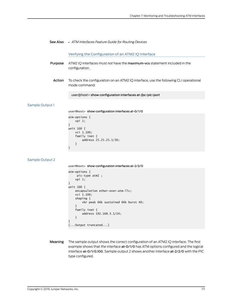
See Also ATM Interfaces Feature Guide for Routing Devices•
Verifying the Configuration of an ATM2 IQ Interface
Purpose ATM2 IQ interfaces must not have themaximum-vcs statement included in the
configuration.
Action To check the configuration on an ATM2 IQ interface, use the following CLI operational
mode command:
user@host> show configuration interfaces at-fpc/pic/port
Sample Output 1
user@host> show configuration interfaces at-0/1/0
atm-options { vpi 1;}unit 100 { vci 1.100; family inet { address 25.25.25.1/30; }}
Sample Output 2
user@host> show configuration interfaces at-2/2/0
atm-options { pic-type atm2 ; vpi 1;}unit 100 { encapsulation ether-over-atm-llc; vci 1.100; shaping { vbr peak 66k sustained 66k burst 40; } family inet { address 192.168.5.1/24; }}[...Output truncated...]
Meaning The sample output shows the correct configuration of an ATM2 IQ interface. The first
example shows that the interface at-0/1/0 has ATM options configured and the logical
interface at-0/1/0.100. Sample output 2 shows another interface at-2/2/0with the PIC
type configured.
171Copyright © 2019, Juniper Networks, Inc.
Chapter 7: Monitoring and Troubleshooting ATM Interfaces

NOTE: The ATM2 IQ interface does not have themaximum-vcs statement
included in the configuration.
See Also ATM Interfaces Feature Guide for Routing Devices•
Verifying the Configuration of an ATMMIC Interface
Purpose Verify that the ATMMIC interface is configured correctly. ATMMIC interfaces do not have
themaximum-cvs and pic-type statements included in the configuration.
Action To check the configuration of the ATMMIC interface:
user@host>show configuration interfaces at-2/2/0
atm-options { vpi 7;}unit 100 { encapsulation atm-vc-mux; vci 7.100 family inet { address 10.10.10.1/32;{ destination 10.10.20.1 } }
}
Meaning The sample output shows the correct configuration of anATMMIC interface. The sample
output shows that the interface at-2/2/0 has ATM options configured.
NOTE: The ATMMIC interface does not have themaximum-cvs statement
or the pic-type statement included in the configuration.
See Also Checklist for Determining ATM Interface Type on page 165•
• Determining the ATM Interface Type and Configuration on page 167
• Examples of Incorrect Configurations of ATMOptions on page 173
• Identifying the ATM Interface Type on page 168
• Monitoring ATMMIC Interfaces on page 194
Copyright © 2019, Juniper Networks, Inc.172
ATM Interfaces Feature Guide for Routing Devices
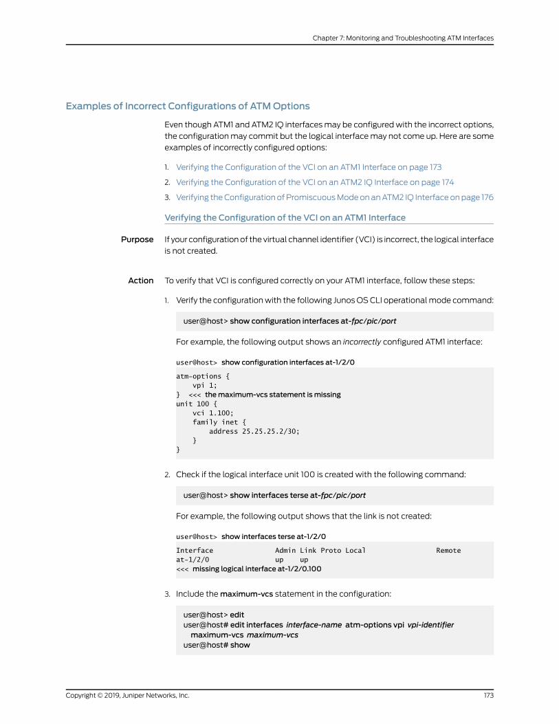
Examples of Incorrect Configurations of ATMOptions
Even though ATM1 and ATM2 IQ interfacesmay be configuredwith the incorrect options,
the configurationmay commit but the logical interfacemay not come up. Here are some
examples of incorrectly configured options:
1. Verifying the Configuration of the VCI on an ATM1 Interface on page 173
2. Verifying the Configuration of the VCI on an ATM2 IQ Interface on page 174
3. Verifying theConfigurationofPromiscuousModeonanATM2 IQ Interfaceonpage 176
Verifying the Configuration of the VCI on an ATM1 Interface
Purpose If your configurationof the virtual channel identifier (VCI) is incorrect, the logical interface
is not created.
Action To verify that VCI is configured correctly on your ATM1 interface, follow these steps:
1. Verify the configurationwith the following JunosOSCLI operationalmode command:
user@host> show configuration interfaces at-fpc/pic/port
For example, the following output shows an incorrectly configured ATM1 interface:
user@host> show configuration interfaces at-1/2/0
atm-options { vpi 1;} <<< themaximum-vcs statement is missingunit 100 { vci 1.100; family inet { address 25.25.25.2/30; }}
2. Check if the logical interface unit 100 is created with the following command:
user@host> show interfaces terse at-fpc/pic/port
For example, the following output shows that the link is not created:
user@host> show interfaces terse at-1/2/0
Interface Admin Link Proto Local Remoteat-1/2/0 up up <<< missing logical interface at-1/2/0.100
3. Include themaximum-vcs statement in the configuration:
user@host> edituser@host# edit interfaces interface-name atm-options vpi vpi-identifiermaximum-vcs maximum-vcs
user@host# show
173Copyright © 2019, Juniper Networks, Inc.
Chapter 7: Monitoring and Troubleshooting ATM Interfaces

user@host# commit
For example, the following output shows a correctly configured ATM1 interface:
user@host> show configuration interfaces at-0/1/0
atm-options { vpi 1 {
maximum-vcs 1024; }}unit 100 { vci 1.100; family inet { address 25.25.25.2/30; }}
1. Check that the logical interface is created with the following command:
user@host> run show interfaces terse at-fpc/pic/port
For example, the following output shows that the link is created:
user@host# run show interfaces terse at-1/2/0
Interface Admin Link Proto Local Remoteat-1/2/0 up up at-1/2/0.100 up up inet 25.25.25.2/30
Meaning The steps above show that initially the logical interface at-1/2/0.100 is not created
because themaximum-vcs statement is not included in the ATM1 configuration. When
that statement is included, the logical interface is created.
See Also ATM Interfaces Feature Guide for Routing Devices•
Verifying the Configuration of the VCI on an ATM2 IQ Interface
Purpose If your configuration of the VCI is incorrect, the logical interface is not created.
Action To check that VCI is configured correctly on your ATM2 IQ interface, follow these steps:
1. Check theconfigurationwith the following JunosOSCLI operationalmodecommand:
user@host> show configuration interfaces at-fpc/pic/port
For example, the following output shows an incorrectly configured ATM2 IQ interface:
user@host> show configuration interfaces at-0/1/0
Copyright © 2019, Juniper Networks, Inc.174
ATM Interfaces Feature Guide for Routing Devices

atm-options { vpi 1 {
maximum-vcs 200; <<< incorrectly included }}unit 100 { vci 1.100; family inet { address 25.25.25.1/30; }}
2. Check if the logical interface unit 100 is created with the following command:
user@host> show interfaces terse at-fpc/pic/port
For example, the following output shows that the link is not created:
user@host> show interfaces terse at-0/1/0
Interface Admin Link Proto Local Remoteat-0/1/0 up up <<< missing logical interface at-0/1/0.100
3. Delete the incorrectmaximum-vcs statement from the configuration:
user@host> edituser@host# edit interfaces interface-name atm-options vpi vpi-identifieruser@host# deletemaximum-vcsuser@host# showuser@host# commit
For example, the following output shows a correctly configured ATM2 IQ interface:
user@host> show configuration interfaces at-0/1/0
atm-options { vpi 1 { }}unit 100 { vci 1.100; family inet { address 25.25.25.1/30; }}
4. Check that the logical interface is created with the following command:
user@host> show interfaces terse at-fpc/pic/port
For example, the following output shows that the link is created:
user@host> show interfaces terse at-0/1/0
175Copyright © 2019, Juniper Networks, Inc.
Chapter 7: Monitoring and Troubleshooting ATM Interfaces

Interface Admin Link Proto Local Remoteat-0/1/0 up up at-0/1/0.100 up up inet 25.25.25.1/30
Meaning The steps above show that initially the logical interface at-0/1/0.100 is not created
because themaximum-vcs statement is included in the ATM2 IQ configuration. When
that statement is deleted, the logical interface is created.
See Also ATM Interfaces Feature Guide for Routing Devices•
Verifying the Configuration of PromiscuousMode on an ATM2 IQ Interface
Purpose If your configurationof promiscuousmode is incorrect, the logical interface is not created.
ATM2 IQ interfaces must have the pic-type atm2 statement included if you are including
the promiscuous-mode statement in the configuration.
Action To check that promiscuous mode is configured correctly on your ATM2 IQ interface,
follow these steps:
1. Check theconfigurationwith the following JunosOSCLI operationalmodecommand:
user@host> show configuration interfaces at-fpc/pic/port
For example, the following output shows promiscuous mode incorrectly configured
on an ATM2 IQ interface:
user@host> show configuration interfaces at-1/2/0
encapsulation atm-ccc-cell-relay;atm-options {
promiscuous-mode { <<< the pic-type statement is missing vpi 1; }}unit 1 { vpi 1;}
2. Check if the logical interface unit 1 is created with the following command:
user@host> run show interfaces terse at-fpc/pic/port
For example, the following output shows that the link is not created:
user@host# run show interfaces terse at-0/1/0
Interface Admin Link Proto Local Remoteat-0/1/0 up up <<< missing logical interface at-0/1/0.1
Copyright © 2019, Juniper Networks, Inc.176
ATM Interfaces Feature Guide for Routing Devices
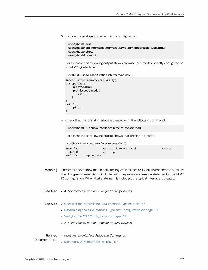
3. Include the pic-type statement in the configuration:
user@host> edituser@host# set interfaces interface-name atm-options pic-type atm2user@host# showuser@host# commit
For example, the following output shows promiscuous mode correctly configured on
an ATM2 IQ interface:
user@host> show configuration interfaces at-0/1/0
encapsulation atm-ccc-cell-relay;atm-options {
pic-type atm2;promiscuous-mode {
vpi 1; }}unit 1 { vpi 1;}
4. Check that the logical interface is created with the following command:
user@host> run show interfaces terse at-fpc/pic/port
For example, the following output shows that the link is created:
user@host# run show interfaces terse at-0/1/0
Interface Admin Link Proto Local Remoteat-0/1/0 up up at-0/1/0.1 up up ccc
Meaning The steps above show that initially the logical interface at-0/1/0.1 is not created because
thepic-typestatement is not includedwith thepromiscuous-mode statement in theATM2
IQ configuration. When that statement is included, the logical interface is created.
See Also ATM Interfaces Feature Guide for Routing Devices•
See Also Checklist for Determining ATM Interface Type on page 165•
• Determining the ATM Interface Type and Configuration on page 167
• Verifying the ATM Configuration on page 169
• ATM Interfaces Feature Guide for Routing Devices
RelatedDocumentation
Investigating Interface Steps and Commands•
• Monitoring ATM Interfaces on page 178
177Copyright © 2019, Juniper Networks, Inc.
Chapter 7: Monitoring and Troubleshooting ATM Interfaces

• Using Loopback Testing for ATM Interfaces on page 208
• Locating ATM Alarms and Errors on page 224
Monitoring ATM Interfaces
• Checklist for Monitoring ATM Interfaces on page 178
• Monitoring ATM Interfaces on page 179
• Monitoring ATM1 Interfaces on page 180
• Monitoring ATM2 IQ Interfaces on page 185
• Monitoring ATMMIC Interfaces on page 194
Checklist for Monitoring ATM Interfaces
Purpose Tomonitor Asynchronous Transfer Mode (ATM) interfaces and begin the process of
isolating ATM interface problems when they occur.
Action Table 19 on page 178 provides the links and commands for monitoring ATM interfaces.
Table 19: Checklist for Monitoring ATM Interfaces
Command or ActionTasks
show interfaces terse at*“Monitoring ATM Interfaces” on page 179
“Monitoring ATM1 Interfaces” on page 180
show interfaces at-fpc/pic/port1. Displaying the Status of a Specific ATM1 Interface onpage 180
show interfaces at-fpc/pic/port extensive2. DisplayingExtensiveStatus Information for aSpecificATM1Interface on page 181
monitor interface at-fpc/pic/port3. “Monitoring Statistics for an ATM1 Interface” on page 183
“Monitoring ATM2 IQ Interfaces” on page 185
show interfaces terse at-fpc/pic/portshow interfaces at-fpc/pic/port
1. Displaying the Status of a Specific ATM2 IQ Interface onpage 185
show interfaces at-fpc/pic/port extensive2. Displaying Extensive Information for a Specific ATM2Interface on page 187
monitor interface at-fpc/pic/port3. Monitoring Statistics for an ATM2 Interface on page 193
“Monitoring ATMMIC Interfaces” on page 194
show interfaces terse at-fpc/pic/portshow interfaces at-fpc/pic/port
1. Displaying the Status of a Specific ATMMIC Interface onpage 194
show interfaces at-fpc/pic/port extensive2. Displaying Extensive Information for a Specific ATMMICInterface on page 196
Copyright © 2019, Juniper Networks, Inc.178
ATM Interfaces Feature Guide for Routing Devices

Table 19: Checklist for Monitoring ATM Interfaces (continued)
Command or ActionTasks
monitor interface at-fpc/pic/port3. Monitoring Traffic and Error Statistics for an ATMMICInterface on page 200
See Also ATM Interfaces Feature Guide for Routing Devices•
Monitoring ATM Interfaces
Purpose Bymonitoring ATM interfaces, you begin the process of isolating ATM interface problems
when they occur. The following command provides the status of all ATM interfaces on
the router. See“Checklist forDeterminingATM InterfaceType”onpage 165 for information
on how to determine the ATM interface type.
Action To display the status of all ATM interfaces, use the following Junos OS command-line
interface (CLI) operational mode command:
user@host> show interfaces terse at*
Sample Output
The following sample output is for an ATM1 interface:
user@host> show interfaces terse at*Interface Admin Link Proto Local Remoteat-2/0/0 up up at-2/2/0.100 up up inet 10.16.5.1/24at-2/2/0.101 up up inet 10.16.250.253/30at-2/2/0.200 up up inet 20.20.20.1/30at-2/2/0.300 up up inet 30.30.30.1/30at-2/2/0.400 up up inet 40.40.40.1/30at-2/2/0.32767 up up at-2/0/1 up downat-2/0/1.10 up down inet 10.10.100.1/30
Meaning Thesampleoutput lists only theATM interfacesandshows the statusofboth thephysical
and logical interfaces. See Table 20 on page 180 for a description of what the output
means. You cannot determine from this outputwhether the interfaces are ATM1 or ATM2
intelligent queuing (IQ). See“Checklist for Determining ATM Interface Type” on page 165
for information on how to determine the ATM interface type.
179Copyright © 2019, Juniper Networks, Inc.
Chapter 7: Monitoring and Troubleshooting ATM Interfaces

Table 20: Status of ATM Interfaces
Status DescriptionLogicalInterface
PhysicalInterface
Both the physical and logical links are up and running onthis interface. By default on an ATM interface, if thephysical link is up, the logical link is also up. However, forATM 1 or ATM2 IQ interfaces with an ATM encapsulationand OAM configured for the VC, even if the physicalinterface is up, the logical link for a VC can be down dueto a VCmisconfiguration.
at-2/0/0.100
Admin Up
Link Up
at-2/0/0
Admin Up
Link Up
The physical link is down on this interface and thereforethe logical interface is down also.
at-2/0/1.10
Admin Up
Link Down
at-2/0/1
Admin Up
Link Down
See Also ATM Interfaces Feature Guide for Routing Devices•
Monitoring ATM1 Interfaces
Tomonitor an ATM1 interface, follow these steps:
1. Displaying the Status of a Specific ATM1 Interface on page 180
2. Displaying Extensive Status Information for a Specific ATM1 Interface on page 181
3. Monitoring Statistics for an ATM1 Interface on page 183
Displaying the Status of a Specific ATM1 Interface
Purpose To display the status of a specific ATM interface, use the following Junos OS CLI
operational mode command:
Action user@host> show interfaces at-fpc/pic/port
Meaning The first line of the sample output shows that the physical link is down and therefore the
logical link is down also. This means that the interface cannot pass packets.
Further down the sample output, look for active alarms and defects. If there are any, and
to further diagnose the problem, see “Displaying Extensive Status Information for a
Specific ATM1 Interface” on page 181 to display more extensive information about the
ATM interface and the physical interface that is down.
See Also ATM Interfaces Feature Guide for Routing Devices•
Copyright © 2019, Juniper Networks, Inc.180
ATM Interfaces Feature Guide for Routing Devices

Displaying Extensive Status Information for a Specific ATM1 Interface
Purpose Todisplayextensive status informationabouta specific interface, use the following Junos
OS CLI operational mode command:
Action user@host> show interfaces at-fpc/pic/port extensive
Sample Output
user@host> show interfaces at-2/0/1 extensive
Physical interface: at-2/0/1, Enabled, Physical link is Down Interface index: 23, SNMP ifIndex: 43, Generation: 22 Link-level type: ATM-PVC, MTU: 4482, Clocking: Internal, SONET mode, Speed: OC3 , Loopback: None, Payload scrambler: Enabled Device flags : Present Running Down Link flags : None Hold-times : Up 0 ms, Down 0 ms Statistics last cleared: 2002-07-29 14:28:14 EDT (00:18:00 ago) Traffic statistics: Input bytes : 0 0 bps Output bytes : 0 0 bps Input packets: 0 0 pps Output packets: 0 0 pps
Input errors: Errors: 0, Drops: 0, Invalid VCs: 0, Framing errors: 0, Policed discards: 0, L3 incompletes: 0, L2 channel errors: 0, L2 mismatch timeouts: 0
Output errors: Carrier transitions: 0, Errors: 0, Drops: 0, Aged packets: 0 SONET alarms : LOL, LOS SONET defects : LOL, LOF, LOS, SEF, AIS-L, AIS-P, RDI-P, PLM-P SONET PHY: Seconds Count State PLL Lock 0 0 OK PHY Light 1079 0 Light Missing SONET section: BIP-B1 0 0 SEF 1079 0 Defect Active LOS 1079 0 Defect Active LOF 1079 0 Defect Active ES-S 1079 SES-S 1079 SEFS-S 1079 SONET line: BIP-B2 0 0 REI-L 0 0 RDI-L 0 0 OK AIS-L 1079 0 Defect Active BERR-SF 0 0 OK BERR-SD 0 0 OK ES-L 1079 SES-L 1079 UAS-L 1079 ES-LFE 0 SES-LFE 0 UAS-LFE 0 SONET path:
181Copyright © 2019, Juniper Networks, Inc.
Chapter 7: Monitoring and Troubleshooting ATM Interfaces
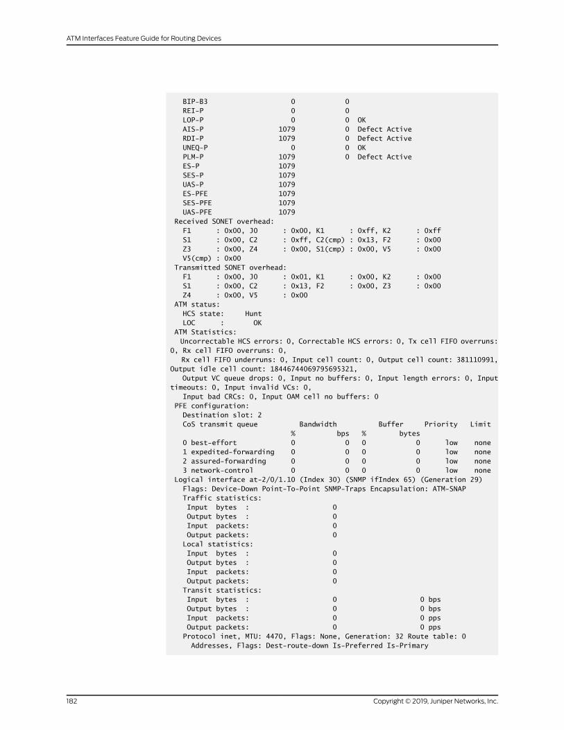
BIP-B3 0 0 REI-P 0 0 LOP-P 0 0 OK AIS-P 1079 0 Defect Active RDI-P 1079 0 Defect Active UNEQ-P 0 0 OK PLM-P 1079 0 Defect Active ES-P 1079 SES-P 1079 UAS-P 1079 ES-PFE 1079 SES-PFE 1079 UAS-PFE 1079 Received SONET overhead: F1 : 0x00, J0 : 0x00, K1 : 0xff, K2 : 0xff S1 : 0x00, C2 : 0xff, C2(cmp) : 0x13, F2 : 0x00 Z3 : 0x00, Z4 : 0x00, S1(cmp) : 0x00, V5 : 0x00 V5(cmp) : 0x00 Transmitted SONET overhead: F1 : 0x00, J0 : 0x01, K1 : 0x00, K2 : 0x00 S1 : 0x00, C2 : 0x13, F2 : 0x00, Z3 : 0x00 Z4 : 0x00, V5 : 0x00 ATM status: HCS state: Hunt LOC : OK ATM Statistics: Uncorrectable HCS errors: 0, Correctable HCS errors: 0, Tx cell FIFO overruns: 0, Rx cell FIFO overruns: 0, Rx cell FIFO underruns: 0, Input cell count: 0, Output cell count: 381110991, Output idle cell count: 18446744069795695321, Output VC queue drops: 0, Input no buffers: 0, Input length errors: 0, Input timeouts: 0, Input invalid VCs: 0, Input bad CRCs: 0, Input OAM cell no buffers: 0 PFE configuration: Destination slot: 2 CoS transmit queue Bandwidth Buffer Priority Limit % bps % bytes 0 best-effort 0 0 0 0 low none 1 expedited-forwarding 0 0 0 0 low none 2 assured-forwarding 0 0 0 0 low none 3 network-control 0 0 0 0 low none Logical interface at-2/0/1.10 (Index 30) (SNMP ifIndex 65) (Generation 29) Flags: Device-Down Point-To-Point SNMP-Traps Encapsulation: ATM-SNAP Traffic statistics: Input bytes : 0 Output bytes : 0 Input packets: 0 Output packets: 0 Local statistics: Input bytes : 0 Output bytes : 0 Input packets: 0 Output packets: 0 Transit statistics: Input bytes : 0 0 bps Output bytes : 0 0 bps Input packets: 0 0 pps Output packets: 0 0 pps Protocol inet, MTU: 4470, Flags: None, Generation: 32 Route table: 0 Addresses, Flags: Dest-route-down Is-Preferred Is-Primary
Copyright © 2019, Juniper Networks, Inc.182
ATM Interfaces Feature Guide for Routing Devices

Destination: 192.168.100.0/30, Local: 192.168.100.1, Broadcast: Unspecified, Generation: 61 VCI 2.100 Flags: Active Total down time: 0 sec, Last down: Never ATM per-VC transmit statistics: Tail queue packet drops: 0 Traffic statistics: Input bytes : 0 Output bytes : 0 Input packets: 0 Output packets:
Meaning The sample output is for an OC3 ATM interface and shows the statistics for the SONET
media, aswell as the Input andOutput ATMerrors. Error details include input and output
errors, active alarms and defects, andmedia-specific errors.
If the physical link is down, look at the active alarms and defects for the ATM interface
and check the ATMmedia accordingly. See“List of Common ATM Alarms and Error” on
page 225 for an explanation of ATM alarms.
See Also ATM Interfaces Feature Guide for Routing Devices•
Monitoring Statistics for an ATM1 Interface
Purpose Tomonitor statistics for an ATM1 interface, use the following Junos OS CLI operational
mode command:
Action user@host>monitor interface at-fpc/pic/port
CAUTION: We recommend that you use this command only for diagnosticpurposes.Donot leave itonduringnormal routeroperationsbecause real-timemonitoring of traffic consumes additional CPU andmemory resources.
Sample Output
user@host> monitor interface at-2/0/0
host Seconds: 68 Time: 13:52:33 Delay: 0/0/2Interface: at-2/0/0, Enabled, Link is UpEncapsulation: ATM-PVC, Speed: OC3Traffic statistics: Current delta Input bytes: 1528168 (2142968 bps) [1528000] Output bytes: 1540192 (2165880 bps) [1540000] Input packets: 1002 (175 pps) [1000] Output packets: 1002 (175 pps) [1000]
183Copyright © 2019, Juniper Networks, Inc.
Chapter 7: Monitoring and Troubleshooting ATM Interfaces
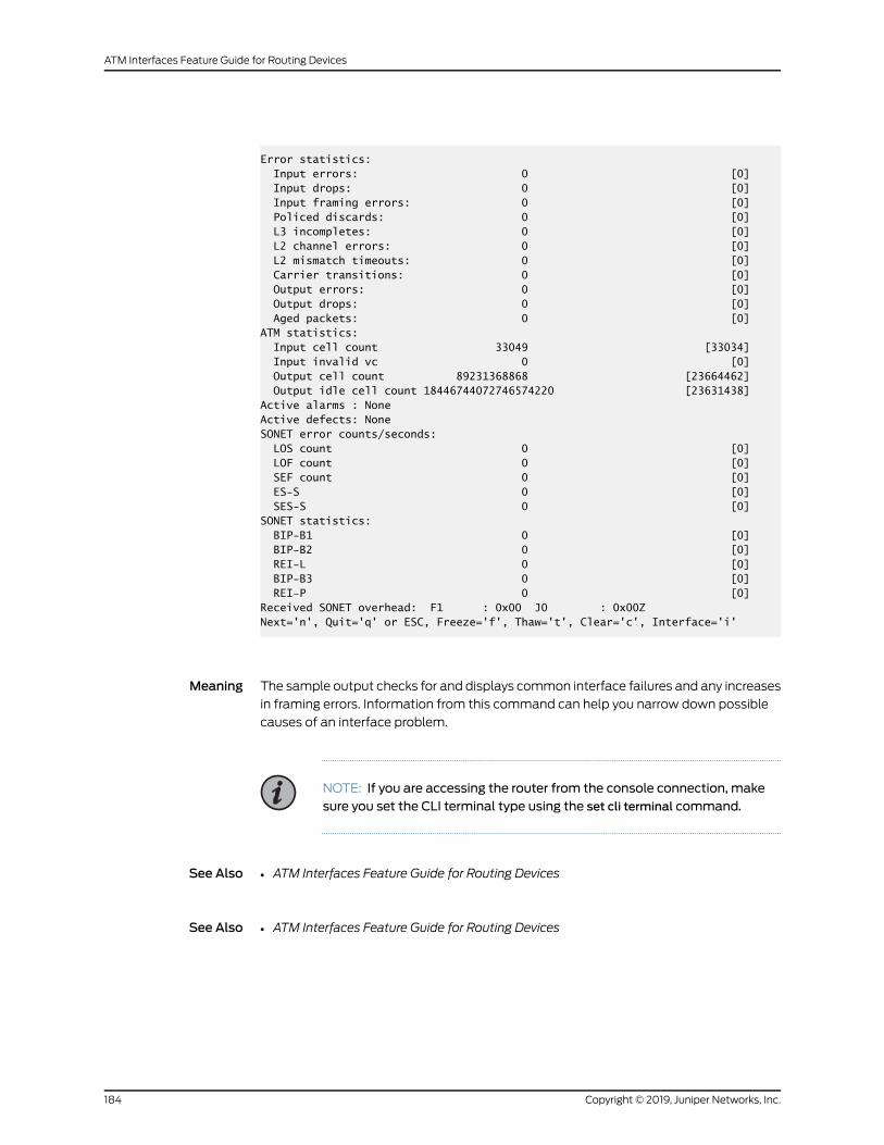
Error statistics: Input errors: 0 [0] Input drops: 0 [0] Input framing errors: 0 [0] Policed discards: 0 [0] L3 incompletes: 0 [0] L2 channel errors: 0 [0] L2 mismatch timeouts: 0 [0] Carrier transitions: 0 [0] Output errors: 0 [0] Output drops: 0 [0] Aged packets: 0 [0]ATM statistics: Input cell count 33049 [33034] Input invalid vc 0 [0] Output cell count 89231368868 [23664462] Output idle cell count 18446744072746574220 [23631438]Active alarms : NoneActive defects: NoneSONET error counts/seconds: LOS count 0 [0] LOF count 0 [0] SEF count 0 [0] ES-S 0 [0] SES-S 0 [0]SONET statistics: BIP-B1 0 [0] BIP-B2 0 [0] REI-L 0 [0] BIP-B3 0 [0] REI-P 0 [0]Received SONET overhead: F1 : 0x00 J0 : 0x00ZNext='n', Quit='q' or ESC, Freeze='f', Thaw='t', Clear='c', Interface='i'
Meaning The sample output checks for and displays common interface failures and any increases
in framing errors. Information from this command can help you narrow down possible
causes of an interface problem.
NOTE: If you are accessing the router from the console connection, makesure you set the CLI terminal type using the set cli terminal command.
See Also ATM Interfaces Feature Guide for Routing Devices•
See Also ATM Interfaces Feature Guide for Routing Devices•
Copyright © 2019, Juniper Networks, Inc.184
ATM Interfaces Feature Guide for Routing Devices

Monitoring ATM2 IQ Interfaces
Tomonitor an ATM2 interface, follow these steps:
1. Displaying the Status of a Specific ATM2 IQ Interface on page 185
2. Displaying Extensive Information for a Specific ATM2 Interface on page 187
3. Monitoring Statistics for an ATM2 Interface on page 193
Displaying the Status of a Specific ATM2 IQ Interface
Purpose To display the status of a specific ATM2 IQ interface, use the following Junos OS CLI
operational mode commands:
Action user@host> show interfaces terse at-fpc/pic/portuser@host> show interfaces at-fpc/pic/port
Sample Output 1
user@host> show interfaces terse at-2/2/0
Interface Admin Link Proto Local Remoteat-2/2/0 up up at-2/2/0.100 up up inet 10.16.5.1/24at-2/2/0.101 up up inet 10.16.250.253/30at-2/2/0.200 up up inet 20.20.20.1/30at-2/2/0.300 up up inet 30.30.30.1/30at-2/2/0.400 up up inet 40.40.40.1/30at-2/2/0.32767 up up
Sample Output 2
user@host> show interfaces at-2/2/0
Physical interface: at-2/2/0, Enabled, Physical link is Up Interface index: 138, SNMP ifIndex: 26 Link-level type: ATM-PVC, MTU: 4482, Clocking: Internal, SONET mode, Speed: OC12, Loopback: None, Payload scrambler: Enabled Device flags : Present Running Link flags : None CoS queues : 4 supported Current address: 00:90:69:d6:d5:3a Last flapped : 2004-05-03 14:32:52 UTC (02:41:35 ago) Input rate : 0 bps (0 pps) Output rate : 0 bps (0 pps) SONET alarms : None SONET defects : None VPI 1 Flags: Active Total down time: 0 sec, Last down: Never Traffic statistics: Input packets: 0 Output packets: 18
Logical interface at-2/2/0.100 (Index 67) (SNMP ifIndex 36) Flags: Point-To-Multipoint SNMP-Traps Encapsulation: Ether-over-ATM-LLC
185Copyright © 2019, Juniper Networks, Inc.
Chapter 7: Monitoring and Troubleshooting ATM Interfaces

Input packets : 0 Output packets: 7 Protocol inet, MTU: 1500 Flags: None Addresses, Flags: Is-Preferred Is-Primary Destination: 172.16.5/24, Local: 172.16.5.1, Broadcast: 172.16.5.255 VCI 1.100 Flags: Active, Shaping, Multicast VBR, Peak: 66kbps, Sustained: 66kbps, Burst size: 40 Total down time: 0 sec, Last down: Never EPD threshold: 0, Transmit weight cells: 0 Input packets : 0 Output packets: 14
Logical interface at-2/2/0.101 (Index 68) (SNMP ifIndex 37) Flags: Point-To-Point SNMP-Traps Encapsulation: ATM-SNAP Input packets : 0 Output packets: 2 Protocol inet, MTU: 4470 Flags: None Addresses, Flags: Is-Preferred Is-Primary Destination: 172.16.250.252/30, Local: 172.16.250.253, Broadcast: 172.16.250.255 VCI 1.101 Flags: Active Total down time: 0 sec, Last down: Never EPD threshold: 0, Transmit weight cells: 0 Input packets : 0 Output packets: 2
Logical interface at-2/2/0.200 (Index 69) (SNMP ifIndex 8280) Flags: Point-To-Point SNMP-Traps Encapsulation: ATM-SNAP Input packets : 0 Output packets: 0 Protocol inet, MTU: 4470 Flags: None Addresses, Flags: Is-Preferred Is-Primary Destination: 20.20.20.0/30, Local: 20.20.20.1, Broadcast: 20.20.20.3 VCI 1.200 Flags: Active Total down time: 0 sec, Last down: Never EPD threshold: 0, Transmit weight cells: 0 Input packets : 0 Output packets: 0
Logical interface at-2/2/0.300 (Index 70) (SNMP ifIndex 8281) Flags: Point-To-Point SNMP-Traps Encapsulation: ATM-SNAP Input packets : 0 Output packets: 0 Protocol inet, MTU: 4470 Flags: None Addresses, Flags: Is-Preferred Is-Primary Destination: 30.30.30.0/30, Local: 30.30.30.1, Broadcast: 30.30.30.3 VCI 1.300 Flags: Active Total down time: 0 sec, Last down: Never EPD threshold: 0, Transmit weight cells: 0 Input packets : 0 Output packets: 0
Logical interface at-2/2/0.400 (Index 72) (SNMP ifIndex 8282) Flags: Point-To-Point SNMP-Traps Encapsulation: ATM-SNAP Input packets : 0 Output packets: 0
Copyright © 2019, Juniper Networks, Inc.186
ATM Interfaces Feature Guide for Routing Devices

Protocol inet, MTU: 4470 Flags: None Addresses, Flags: Is-Preferred Is-Primary Destination: 40.40.40.0/30, Local: 40.40.40.1, Broadcast: 40.40.40.3 VCI 1.400 Flags: Active Total down time: 0 sec, Last down: Never EPD threshold: 0, Transmit weight cells: 0 Input packets : 0 Output packets: 0
Logical interface at-2/2/0.32767 (Index 71) (SNMP ifIndex 27) Flags: Point-To-Multipoint No-Multicast SNMP-Traps Encapsulation: ATM-VCMUX Input packets : 0 Output packets: 0 VCI 1.4 Flags: Active Total down time: 0 sec, Last down: Never EPD threshold: 0, Transmit weight cells: 0 Input packets : 0 Output packets: 0
Meaning The first line of the sample output shows that the physical link and all logical links are
up. This means that the interface can pass packets.
Further down the sample output, look for active alarms and defects. If there are any, and
to further diagnose the problem, see “Displaying Extensive Information for a Specific
ATM2 Interface”onpage 187 todisplaymoreextensive informationabout theATMinterface
and the physical interface that is down.
See Also Displaying Extensive Information for a Specific ATM2 Interface on page 187•
• Monitoring Statistics for an ATM2 Interface on page 193
• Monitoring ATM2 IQ Interfaces on page 185
Displaying Extensive Information for a Specific ATM2 Interface
Purpose Todisplayextensive status informationaboutaspecificATM2 interface, use the following
Junos OS CLI operational mode command:
Action user@host> show interfaces at-fpc/pic/port extensive
Sample Output
user@host> show interfaces at-2/2/0 extensive
Physical interface: at-2/2/0, Enabled, Physical link is Up Interface index: 138, SNMP ifIndex: 26, Generation: 21 Link-level type: ATM-PVC, MTU: 4482, Clocking: Internal, SONET mode, Speed: OC12, Loopback: None, Payload scrambler: Enabled Device flags : Present Running
187Copyright © 2019, Juniper Networks, Inc.
Chapter 7: Monitoring and Troubleshooting ATM Interfaces

Link flags : None CoS queues : 4 supported Hold-times : Up 0 ms, Down 0 ms Current address: 00:90:69:d6:d5:3a Last flapped : 2004-05-03 14:32:52 UTC (02:42:30 ago) Statistics last cleared: Never Traffic statistics: Input bytes : 0 0 bps Output bytes : 1600 0 bps Input packets: 0 0 pps Output packets: 18 0 pps Input errors: Errors: 0, Drops: 0, Invalid VCs: 0, Framing errors: 0, Policed discards: 0, L3 incompletes: 0, L2 channel errors: 0, L2 mismatch timeouts: 0 Output errors: Carrier transitions: 1, Errors: 0, Drops: 0, Aged packets: 0 Queue counters: Queued packets Transmitted packets Dropped packets
0 assured-forw 18 18 0
1 expedited-fo 0 0 0
2 best-effort 0 0 0
3 network-cont 0 0 0
SONET alarms : None SONET defects : None SONET PHY: Seconds Count State PLL Lock 0 0 OK PHY Light 0 0 OK SONET section: BIP-B1 1 13 SEF 0 0 OK LOS 0 0 OK LOF 0 0 OK ES-S 1 SES-S 0 SEFS-S 0 SONET line: BIP-B2 1 196 REI-L 1 291 RDI-L 0 0 OK AIS-L 0 0 OK BERR-SF 0 0 OK BERR-SD 0 0 OK ES-L 1 SES-L 0 UAS-L 0 ES-LFE 1 SES-LFE 0 UAS-LFE 0 SONET path: BIP-B3 1 36 REI-P 1 211 LOP-P 0 0 OK AIS-P 0 0 OK RDI-P 0 0 OK UNEQ-P 0 0 OK
Copyright © 2019, Juniper Networks, Inc.188
ATM Interfaces Feature Guide for Routing Devices

PLM-P 0 0 OK ES-P 1 SES-P 0 UAS-P 0 ES-PFE 1 SES-PFE 0 UAS-PFE 0 Received SONET overhead: F1 : 0x00, J0 : 0x00, K1 : 0x00, K2 : 0x00 S1 : 0x00, C2 : 0x13, C2(cmp) : 0x13, F2 : 0x00 Z3 : 0x00, Z4 : 0x00, S1(cmp) : 0x00 Transmitted SONET overhead: F1 : 0x00, J0 : 0x01, K1 : 0x00, K2 : 0x00 S1 : 0x00, C2 : 0x13, F2 : 0x00, Z3 : 0x00 Z4 : 0x00 ATM status: HCS state: Sync LOC : OK ATM Statistics: Uncorrectable HCS errors: 177, Correctable HCS errors: 3, Tx cell FIFO overruns: 0, Rx cell FIFO overruns: 0, Rx cell FIFO underruns: 0, Input cell count: 4, Output cell count: 13785683517, Output idle cell count: 0, Output VC queue drops: 0, Input no buffers: 0, Input length errors: 0, Input timeouts: 0, Input invalid VCs: 2, Input bad CRCs: 0, Input OAM cell no buffers: 0 Packet Forwarding Engine configuration: Destination slot: 2 VPI 1 Flags: Active Total down time: 0 sec, Last down: Never Traffic statistics: Input bytes : 0 Output bytes : 1600 Input packets: 0 Output packets: 18Logical interface at-2/2/0.100 (Index 67) (SNMP ifIndex 36) (Generation 11)
Flags: Point-To-Multipoint SNMP-Traps Encapsulation: Ether-over-ATM-LLC Traffic statistics: Input bytes : 0 Output bytes : 896 Input packets: 0 Output packets: 7 Local statistics: Input bytes : 0 Output bytes : 896 Input packets: 0 Output packets: 7 Transit statistics: Input bytes : 0 0 bps Output bytes : 0 0 bps Input packets: 0 0 pps Output packets: 0 0 pps Protocol inet, MTU: 1500, Generation: 17, Route table: 0 Flags: None Addresses, Flags: Is-Preferred Is-Primary Destination: 172.16.5/24, Local: 172.16.5.1, Broadcast: 172.16.5.255, Generation: 16 VCI 1.100
189Copyright © 2019, Juniper Networks, Inc.
Chapter 7: Monitoring and Troubleshooting ATM Interfaces

Flags: Active, Shaping, Multicast VBR, Peak: 66kbps, Sustained: 66kbps, Burst size: 40 Total down time: 0 sec, Last down: Never EPD threshold: 0, Transmit weight cells: 0 ATM per-VC transmit statistics: Tail queue packet drops: 0 Traffic statistics: Input bytes : 0 Output bytes : 1512 Input packets: 0 Output packets: 14
Logical interface at-2/2/0.101 (Index 68) (SNMP ifIndex 37) (Generation 12) Flags: Point-To-Point SNMP-Traps Encapsulation: ATM-SNAP Traffic statistics: Input bytes : 0 Output bytes : 200 Input packets: 0 Output packets: 2 Local statistics: Input bytes : 0 Output bytes : 200 Input packets: 0 Output packets: 2 Transit statistics: Input bytes : 0 0 bps Output bytes : 0 0 bps Input packets: 0 0 pps Output packets: 0 0 pps Protocol inet, MTU: 4470, Generation: 18, Route table: 0 Flags: None Addresses, Flags: Is-Preferred Is-Primary Destination: 172.16.250.252/30, Local: 172.16.250.253, Broadcast: 172.16.250.255, Generation: 18 VCI 1.101 Flags: Active Total down time: 0 sec, Last down: Never EPD threshold: 0, Transmit weight cells: 0 ATM per-VC transmit statistics: Tail queue packet drops: 0 Traffic statistics: Input bytes : 0 Output bytes : 184 Input packets: 0 Output packets: 2
Logical interface at-2/2/0.200 (Index 69) (SNMP ifIndex 8280) (Generation 13) Flags: Point-To-Point SNMP-Traps Encapsulation: ATM-SNAP Traffic statistics: Input bytes : 0 Output bytes : 0 Input packets: 0 Output packets: 0 Local statistics: Input bytes : 0 Output bytes : 0 Input packets: 0 Output packets: 0 Transit statistics: Input bytes : 0 0 bps Output bytes : 0 0 bps
Copyright © 2019, Juniper Networks, Inc.190
ATM Interfaces Feature Guide for Routing Devices

Input packets: 0 0 pps Output packets: 0 0 pps Protocol inet, MTU: 4470, Generation: 19, Route table: 0 Flags: None Addresses, Flags: Is-Preferred Is-Primary Destination: 20.20.20.0/30, Local: 20.20.20.1, Broadcast: 20.20.20.3, Generation: 20 VCI 1.200 Flags: Active Total down time: 0 sec, Last down: Never EPD threshold: 0, Transmit weight cells: 0 ATM per-VC transmit statistics: Tail queue packet drops: 0 Traffic statistics: Input bytes : 0 Output bytes : 0 Input packets: 0 Output packets: 0Logical interface at-2/2/0.300 (Index 70) (SNMP ifIndex 8281) (Generation 14)
Flags: Point-To-Point SNMP-Traps Encapsulation: ATM-SNAP Traffic statistics: Input bytes : 0 Output bytes : 0 Input packets: 0 Output packets: 0 Local statistics: Input bytes : 0 Output bytes : 0 Input packets: 0 Output packets: 0 Transit statistics: Input bytes : 0 0 bps Output bytes : 0 0 bps Input packets: 0 0 pps Output packets: 0 0 pps Protocol inet, MTU: 4470, Generation: 20, Route table: 0 Flags: None Addresses, Flags: Is-Preferred Is-Primary Destination: 30.30.30.0/30, Local: 30.30.30.1, Broadcast: 30.30.30.3, Generation: 22 VCI 1.300 Flags: Active Total down time: 0 sec, Last down: Never EPD threshold: 0, Transmit weight cells: 0 ATM per-VC transmit statistics: Tail queue packet drops: 0 Traffic statistics: Input bytes : 0 Output bytes : 0 Input packets: 0 Output packets: 0Logical interface at-2/2/0.400 (Index 72) (SNMP ifIndex 8282) (Generation 15)
Flags: Point-To-Point SNMP-Traps Encapsulation: ATM-SNAP Traffic statistics: Input bytes : 0 Output bytes : 0 Input packets: 0 Output packets: 0 Local statistics: Input bytes : 0
191Copyright © 2019, Juniper Networks, Inc.
Chapter 7: Monitoring and Troubleshooting ATM Interfaces

Output bytes : 0 Input packets: 0 Output packets: 0 Transit statistics: Input bytes : 0 0 bps Output bytes : 0 0 bps Input packets: 0 0 pps Output packets: 0 0 pps Protocol inet, MTU: 4470, Generation: 21, Route table: 0 Flags: None Addresses, Flags: Is-Preferred Is-Primary Destination: 40.40.40.0/30, Local: 40.40.40.1, Broadcast: 40.40.40.3, Generation: 24 VCI 1.400 Flags: Active Total down time: 0 sec, Last down: Never EPD threshold: 0, Transmit weight cells: 0 ATM per-VC transmit statistics: Tail queue packet drops: 0 Traffic statistics: Input bytes : 0 Output bytes : 0 Input packets: 0 Output packets: 0Logical interface at-2/2/0.32767 (Index 71) (SNMP ifIndex 27) (Generation 9)
Flags: Point-To-Multipoint No-Multicast SNMP-Traps Encapsulation: ATM-VCMUX Traffic statistics: Input bytes : 0 Output bytes : 0 Input packets: 0 Output packets: 0 Local statistics: Input bytes : 0 Output bytes : 0 Input packets: 0 Output packets: 0 VCI 1.4 Flags: Active Total down time: 0 sec, Last down: Never EPD threshold: 0, Transmit weight cells: 0 ATM per-VC transmit statistics: Tail queue packet drops: 0 Traffic statistics: Input bytes : 0 Output bytes : 0 Input packets: 0 Output packets: 0
Meaning The sample output is for an OC12 ATM interface and shows the statistics for the SONET
media, aswell as the Input andOutput ATMerrors. Error details include input and output
errors, active alarms and defects, andmedia-specific errors.
If the physical link is down, look at the active alarms and defects for the ATM interface
and check the ATMmedia accordingly. See“List of Common ATM Alarms and Error” on
page 225 for an explanation of ATM alarms.
Copyright © 2019, Juniper Networks, Inc.192
ATM Interfaces Feature Guide for Routing Devices

See Also Displaying the Status of a Specific ATM2 IQ Interface on page 185•
• Monitoring Statistics for an ATM2 Interface on page 193
• Monitoring ATM2 IQ Interfaces on page 185
Monitoring Statistics for an ATM2 Interface
Purpose Tomonitor statistics for an ATM2 interface, use the following Junos OS CLI operational
mode command:
Action user@host>monitor interface at-fpc/pic/port
CAUTION: We recommend that you use this command only for diagnosticpurposes.Donot leave itonduringnormal routeroperationsbecause real-timemonitoring of traffic consumes additional CPU andmemory resources.
Sample Output
user@host> monitor interface at-2/2/0
host Seconds: 5 Time: 17:16:49 Delay: 3/0/3Interface: at-2/2/0, Enabled, Link is UpEncapsulation: ATM-PVC, Speed: OC12Traffic statistics: Current delta Input bytes: 0 (0 bps) [0] Output bytes: 1600 (0 bps) [0] Input packets: 0 (0 pps) [0] Output packets: 18 (0 pps) [0]Error statistics: Input errors: 0 [0] Input drops: 0 [0] Input framing errors: 0 [0] Policed discards: 0 [0] L3 incompletes: 0 [0] L2 channel errors: 0 [0] L2 mismatch timeouts: 0 [0] Carrier transitions: 1 [0] Output errors: 0 [0] Output drops: 0 [0] Aged packets: 0 [0]ATM statistics: Input cell count 4 [0] Input invalid vc 2 [0] Output cell count 13908633088 [8484369] Output idle cell count 0 [0]Active alarms : NoneActive defects: NoneSONET error countsZ [0]
193Copyright © 2019, Juniper Networks, Inc.
Chapter 7: Monitoring and Troubleshooting ATM Interfaces

Meaning The sample output checks for and displays common interface failures and any increases
in framing errors. Information from this command can help you narrow down possible
causes of an interface problem.
NOTE: If you are accessing the router from the console connection, makesure you set the CLI terminal type using the set cli terminal command.
See Also Displaying the Status of a Specific ATM2 IQ Interface on page 185•
• Displaying Extensive Information for a Specific ATM2 Interface on page 187
• Monitoring ATM2 IQ Interfaces on page 185
See Also Checklist for Monitoring ATM Interfaces on page 178•
• Monitoring ATM Interfaces on page 179
• Monitoring ATM1 Interfaces on page 180
Monitoring ATMMIC Interfaces
Tomonitor the status of ATMMIC interfaces, perform the following tasks:
• Displaying the Status of a Specific ATMMIC Interface on page 194
• Displaying Extensive Information for a Specific ATMMIC Interface on page 196
• Monitoring Traffic and Error Statistics for an ATMMIC Interface on page 200
Displaying the Status of a Specific ATMMIC Interface
Purpose Display the status of a specific ATMMIC interface.
Action To display the summary information about a specific ATMMIC interface:
user@host> show interfaces terse at-2/2/0
Interface Admin Link Proto Local Remoteat-2/2/0 up up at-2/2/0.100 up up inet 10.10.10.1 --> 10.10.20.1at-2/2/0.32767 up up
To display the status of a specific ATMMIC interface:
user@host> show interfaces at-2/2/0
Copyright © 2019, Juniper Networks, Inc.194
ATM Interfaces Feature Guide for Routing Devices

Sample Output
Physical interface: at-2/2/0, Enabled, Physical link is Up Interface index: 146, SNMP ifIndex: 510 Link-level type: ATM-PVC, MTU: 9192, Clocking: Internal, SONET mode, Speed: OC3, Loopback: None, Payload scrambler: Enabled Device flags : Present Running Link flags : None CoS queues : 8 supported, 8 maximum usable queues Schedulers : 0 Current address: 00:26:88:da:a6:74 Last flapped : 2012-03-07 11:02:11 PST (5w4d 15:45 ago) Input rate : 0 bps (0 pps) Output rate : 0 bps (0 pps) SONET alarms : None SONET defects : None VPI 7 Flags: Active Total down time: 0 sec, Last down: Never Traffic statistics: Input packets: 0 Output packets: 0
Logical interface at-2/2/0.100 (Index 347) (SNMP ifIndex 518) Flags: Point-To-Point SNMP-Traps 0x4000 Encapsulation: ATM-VCMUX Input packets : 0 Output packets: 0 Protocol inet, MTU: 2040 Flags: Sendbcast-pkt-to-re Addresses, Flags: Is-Preferred Is-Primary Destination: 10.10.20.1, Local: 10.10.10.1 VCI 7.100 Flags: Active Total down time: 0 sec, Last down: Never Input packets : 0 Output packets: 0
Logical interface at-2/2/0.32767 (Index 348) (SNMP ifIndex 519) Flags: Point-To-Multipoint No-Multicast SNMP-Traps 0x4000 Encapsulation: ATM-VCMUX Input packets : 0 Output packets: 0 VCI 7.4 Flags: Active Total down time: 0 sec, Last down: Never Input packets : 0 Output packets: 0
Meaning The first line of the sample output shows that the physical link and all logical links are
up. This means that the interface can pass packets.
Further down the sample output, look for active alarms and defects. If there are any, and
to further diagnose the problem, see “Displaying Extensive Information for a Specific
ATMMIC Interface” on page 196 to display more extensive information about the ATM
interface and the physical interface that is down.
195Copyright © 2019, Juniper Networks, Inc.
Chapter 7: Monitoring and Troubleshooting ATM Interfaces

Table 21 on page 196 lists the show interfaces terse command output fields.
Table 21: show interfaces terse Output Fields
Field DescriptionField Name
Interface name.Interface
The administrative status of the interface. Possiblevalues: up or down.
Admin
Status of the link. Possible values: up or down.Link
Protocol family configured on the logical interface.Proto
Local IP address of the logical interface.Local
Remote IP address of the logical interface.Remote
For information about the output fields of the show interfaces command, see showinterfaces (ATM).
Displaying Extensive Information for a Specific ATMMIC Interface
Purpose Display extensive information for a specific ATMMIC interface.
Action To display extensive status information about a specific ATMMIC interface:
user@host>show interfaces at-2/2/0 extensive
Physical interface: at-2/2/0, Enabled, Physical link is Up Interface index: 146, SNMP ifIndex: 510, Generation: 421 Link-level type: ATM-PVC, MTU: 9192, Clocking: Internal, SONET mode, Speed: OC3, Loopback: None, Payload scrambler: Enabled Device flags : Present Running Link flags : None CoS queues : 8 supported, 8 maximum usable queues Schedulers : 0 Hold-times : Up 0 ms, Down 0 ms Current address: 00:26:88:da:a6:74 Last flapped : 2012-03-07 11:02:11 PST (5w4d 15:58 ago) Statistics last cleared: Never Traffic statistics: Input bytes : 0 0 bps Output bytes : 0 0 bps Input packets: 0 0 pps Output packets: 0 0 pps IPv6 transit statistics: Input bytes : 0 Output bytes : 0 Input packets: 0 Output packets: 0
Copyright © 2019, Juniper Networks, Inc.196
ATM Interfaces Feature Guide for Routing Devices

Input errors: Errors: 0, Drops: 0, Invalid VCs: 0, Framing errors: 0, Policed discards: 0,
L3 incompletes: 0, L2 channel errors: 0, L2 mismatch timeouts: 0, Resource errors: 0 Output errors: Carrier transitions: 1, Errors: 0, Drops: 0, Aged packets: 0, MTU errors: 0,
Resource errors: 0 Egress queues: 8 supported, 4 in use Queue counters: Queued packets Transmitted packets Dropped packets
0 best-effort 0 0 0
1 expedited-fo 0 0 0
2 assured-forw 0 0 0
3 network-cont 0 0 0
Queue number: Mapped forwarding classes 0 best-effort 1 expedited-forwarding 2 assured-forwarding 3 network-control SONET alarms : None SONET defects : None SONET PHY: Seconds Count State PLL Lock 0 0 OK PHY Light 0 0 OK SONET section: BIP-B1 1 29 SEF 0 0 OK LOS 0 0 OK LOF 0 0 OK ES-S 1 SES-S 0 SEFS-S 0 SONET line: BIP-B2 1 75 REI-L 1 36 RDI-L 0 0 OK AIS-L 0 0 OK BERR-SF 0 0 OK BERR-SD 0 0 OK ES-L 1 SES-L 0 UAS-L 0 ES-LFE 1 SES-LFE 0 UAS-LFE 0 SONET path: BIP-B3 1 23 REI-P 1 34 LOP-P 0 0 OK AIS-P 0 0 OK RDI-P 0 0 OK UNEQ-P 0 0 OK PLM-P 0 0 OK ES-P 1
197Copyright © 2019, Juniper Networks, Inc.
Chapter 7: Monitoring and Troubleshooting ATM Interfaces

SES-P 0 UAS-P 0 ES-PFE 1 SES-PFE 0 UAS-PFE 0 Payload pointer: Current pointer : 0 Pointer increment count : 0 Pointer decrement count : 0 New pointer NDF count : 1 Received SONET overhead: F1 : 0x00, J0 : 0x00, K1 : 0x00, K2 : 0x00 S1 : 0x00, C2 : 0x13, C2(cmp) : 0x13, F2 : 0x00 Z3 : 0x00, Z4 : 0x00, S1(cmp) : 0x00 Transmitted SONET overhead: F1 : 0x00, J0 : 0x01, K1 : 0x00, K2 : 0x00 S1 : 0x00, C2 : 0x13, F2 : 0x00, Z3 : 0x00 Z4 : 0x00 ATM status: HCS state: Sync LOC : OK ATM Statistics: Uncorrectable HCS errors: 7, Correctable HCS errors: 0, Tx cell FIFO overruns: 0, Rx cell FIFO overruns: 0, Rx cell FIFO underruns: 0, Input cell count: 0, Output cell count: 0, Output idle cell count: 1210483921034, Output VC queue drops: 0, Input no buffers: 0, Input length errors: 0, Input timeouts: 0, Input invalid VCs: 0, Input bad CRCs: 0, Input OAM cell no buffers: 0 Packet Forwarding Engine configuration: Destination slot: 2 VPI 7 Flags: Active Total down time: 0 sec, Last down: Never Traffic statistics: Input bytes : 0 Output bytes : 0 Input packets: 0 Output packets: 0
Logical interface at-2/2/0.100 (Index 347) (SNMP ifIndex 518) (Generation 660) Flags: Point-To-Point SNMP-Traps 0x4000 Encapsulation: ATM-VCMUX Traffic statistics: Input bytes : 0 Output bytes : 0 Input packets: 0 Output packets: 0 Local statistics: Input bytes : 0 Output bytes : 0 Input packets: 0 Output packets: 0 Transit statistics: Input bytes : 0 0 bps Output bytes : 0 0 bps Input packets: 0 0 pps Output packets: 0 0 pps Protocol inet, MTU: 2040, Generation: 457, Route table: 0 Flags: Sendbcast-pkt-to-re Addresses, Flags: Is-Preferred Is-Primary
Copyright © 2019, Juniper Networks, Inc.198
ATM Interfaces Feature Guide for Routing Devices
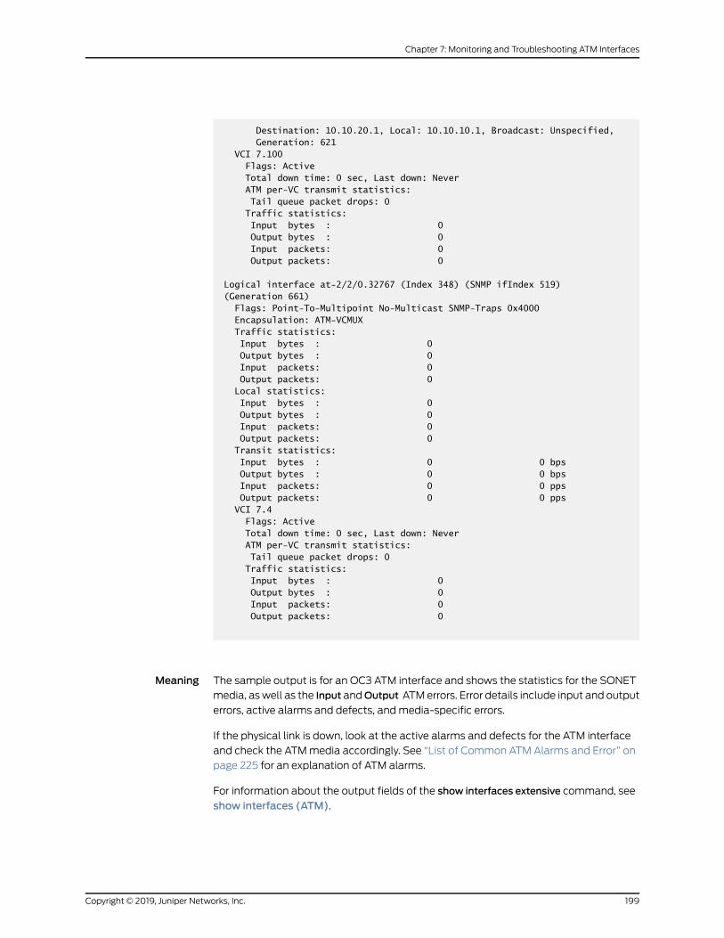
Destination: 10.10.20.1, Local: 10.10.10.1, Broadcast: Unspecified, Generation: 621 VCI 7.100 Flags: Active Total down time: 0 sec, Last down: Never ATM per-VC transmit statistics: Tail queue packet drops: 0 Traffic statistics: Input bytes : 0 Output bytes : 0 Input packets: 0 Output packets: 0
Logical interface at-2/2/0.32767 (Index 348) (SNMP ifIndex 519) (Generation 661) Flags: Point-To-Multipoint No-Multicast SNMP-Traps 0x4000 Encapsulation: ATM-VCMUX Traffic statistics: Input bytes : 0 Output bytes : 0 Input packets: 0 Output packets: 0 Local statistics: Input bytes : 0 Output bytes : 0 Input packets: 0 Output packets: 0 Transit statistics: Input bytes : 0 0 bps Output bytes : 0 0 bps Input packets: 0 0 pps Output packets: 0 0 pps VCI 7.4 Flags: Active Total down time: 0 sec, Last down: Never ATM per-VC transmit statistics: Tail queue packet drops: 0 Traffic statistics: Input bytes : 0 Output bytes : 0 Input packets: 0 Output packets: 0
Meaning The sample output is for an OC3 ATM interface and shows the statistics for the SONET
media, aswell as the Input andOutput ATMerrors. Error details include input and output
errors, active alarms and defects, andmedia-specific errors.
If the physical link is down, look at the active alarms and defects for the ATM interface
and check the ATMmedia accordingly. See “List of Common ATM Alarms and Error” on
page 225 for an explanation of ATM alarms.
For information about the output fields of the show interfaces extensive command, see
show interfaces (ATM).
199Copyright © 2019, Juniper Networks, Inc.
Chapter 7: Monitoring and Troubleshooting ATM Interfaces

Monitoring Traffic and Error Statistics for an ATMMIC Interface
Purpose Monitor traffic and error statistics for an ATMMIC interface.
Action To display real-time statistics, updated every second, for an ATMMIC interface:
CAUTION: We recommend that you use this command only for diagnosticpurposes. If youusethiscommandduringnormal routeroperations,additionalCPU andmemory resources are consumed.
user@host>monitor interface at-2/2/0
host Seconds: 5 Time: 04:02:22 Delay: 0/0/3Interface: at-2/2/0, Enabled, Link is UpEncapsulation: ATM-PVC, Speed: OC3Traffic statistics: Input bytes: 0 (0 bps) Output bytes: 0 (0 bps) Input packets: 0 (0 pps) Output packets: 0 (0 pps)Error statistics: Input errors: 0 Input drops: 0 Input framing errors: 0 Policed discards: 0 L3 incompletes: 0 L2 channel errors: 0 L2 mismatch timeouts: 0 Carrier transitiZ
host Seconds: 5 Time: 04:02:22 Delay: 1/1/1Interface: at-2/2/1, Enabled, Link is UpEncapsulation: ATM-PVC, Speed: OC3Traffic statistics: Current delta Input bytes: 0 (0 bps) [0] Output bytes: 0 (0 bps) [0] Input packets: 0 (0 pps) [0] Output packets: 0 (0 pps) [0]Error statistics: Input errors: 0 [0] Input drops: 0 [0] Input framing errors: 0 [0] Policed discards: 0 [0] L3 incompletes: 0 [0] L2 channel errors: 0 [0] L2 mismatch timeouts: 0 Carrier transitiZ [0]
Copyright © 2019, Juniper Networks, Inc.200
ATM Interfaces Feature Guide for Routing Devices

Meaning Thesampleoutputdisplayscommon interface failuresandany increase in framingerrors.
Information fromthis commandcanhelpyounarrowdownpossiblecausesofan interface
problem.
NOTE: If you are accessing the router from the console connection, makesure you set the CLI terminal type using the set cli terminal command.
For information about the output fields of themonitor interfaces (ATM) command, see
monitor interface.
See Also Verifying the Configuration of an ATMMIC Interface on page 172•
• Identifying the ATM Interface Type on page 168
RelatedDocumentation
Investigating Interface Steps and Commands•
• Determining ATM Interface Type on page 165
• Using Loopback Testing for ATM Interfaces on page 208
• Locating ATM Alarms and Errors on page 224
Configuring Interface Diagnostics Tools to Test the Physical Layer Connections
• Configuring Loopback Testing on page 201
• Configuring BERT Testing on page 203
• Starting and Stopping a BERT Test on page 207
Configuring Loopback Testing
Loopback testing allows you to verify the connectivity of a circuit. You can configure any
of the following interfaces toexecutea loopback test: aggregatedEthernet, Fast Ethernet,
Gigabit Ethernet, E1, E3, NxDS0, serial, SONET/SDH, T1, and T3.
The physical path of a network data circuit usually consists of segments interconnected
by devices that repeat and regenerate the transmission signal. The transmit path on one
device connects to the receive path on the next device. If a circuit fault occurs in the form
of a line break or a signal corruption, you can isolate the problem by using a loopback
test. Loopback testsallowyou to isolate segmentsof thecircuit and test themseparately.
To do this, configure a line loopback on one of the routers. Instead of transmitting the
signal toward the far-enddevice, the line loopback sends the signal back to theoriginating
router. If the originating router receives back its own Data Link Layer packets, you have
verified that the problem is beyond the originating router. Next, configure a line loopback
farther away from the local router. If this originating router does not receive its own Data
Link Layer packets, you can assume that the problem is on one of the segments between
the local router and the remote router’s interface card. In this case, the next
201Copyright © 2019, Juniper Networks, Inc.
Chapter 7: Monitoring and Troubleshooting ATM Interfaces

troubleshooting step is to configure a line loopback closer to the local router to find the
source of the problem.
The following types of loopback testing are supported by Junos OS:
• DCE local—Loopspacketsbackon the localdatacircuit-terminatingequipment (DCE).
• DCE remote—Loops packets back on the remote DCE.
• Local—Useful for troubleshooting physical PIC errors. Configuring local loopback on
an interface allows transmission of packets to the channel service unit (CSU) and then
to the circuit toward the far-end device. The interface receives its own transmission,
which includesdataand timing information, on the local router'sPIC.Thedata received
from the CSU is ignored. To test a local loopback, issue the show interfaces
interface-name command. If PPP keepalives transmitted on the interface are received
by the PIC, the Device Flags field contains the output Loop-Detected.
• Payload—Useful for troubleshooting the physical circuit problems between the local
router and the remote router. A payload loopback loops data only (without clocking
information) on the remote router’s PIC. With payload loopback, overhead is
recalculated.
• Remote—Useful for troubleshooting the physical circuit problems between the local
router and the remote router. A remote loopback loops packets, including both data
and timing information, back on the remote router’s interface card. A router at one end
of thecircuit initiatesa remote loopback toward its remotepartner.Whenyouconfigure
a remote loopback, thepackets received fromthephysical circuit andCSUare received
by the interface. Those packets are then retransmitted by the PIC back toward the
CSU and the circuit. This loopback tests all the intermediate transmission segments.
Table22onpage202showsthe loopbackmodessupportedon thevarious interface types.
Table 22: Loopback Modes by Interface Type
Usage GuidelinesLoopback ModesInterface
Configuring Ethernet Loopback CapabilityLocalAggregated Ethernet,Fast Ethernet, GigabitEthernet
Configuring E1 Loopback CapabilityLocal and remoteCircuit Emulation E1
Configuring T1 Loopback CapabilityLocal and remoteCircuit Emulation T1
Configuring E1 Loopback Capability andConfiguring E3 Loopback Capability
Local and remoteE1 and E3
Configuring NxDS0 IQ and IQE Interfaces,ConfiguringT1andNxDS0 Interfaces,ConfiguringChannelized OC12/STM4 IQ and IQE Interfaces(SONETMode),Configuring Fractional E1 IQandIQE Interfaces, and Configuring Channelized T3IQ Interfaces
PayloadNxDS0
Copyright © 2019, Juniper Networks, Inc.202
ATM Interfaces Feature Guide for Routing Devices
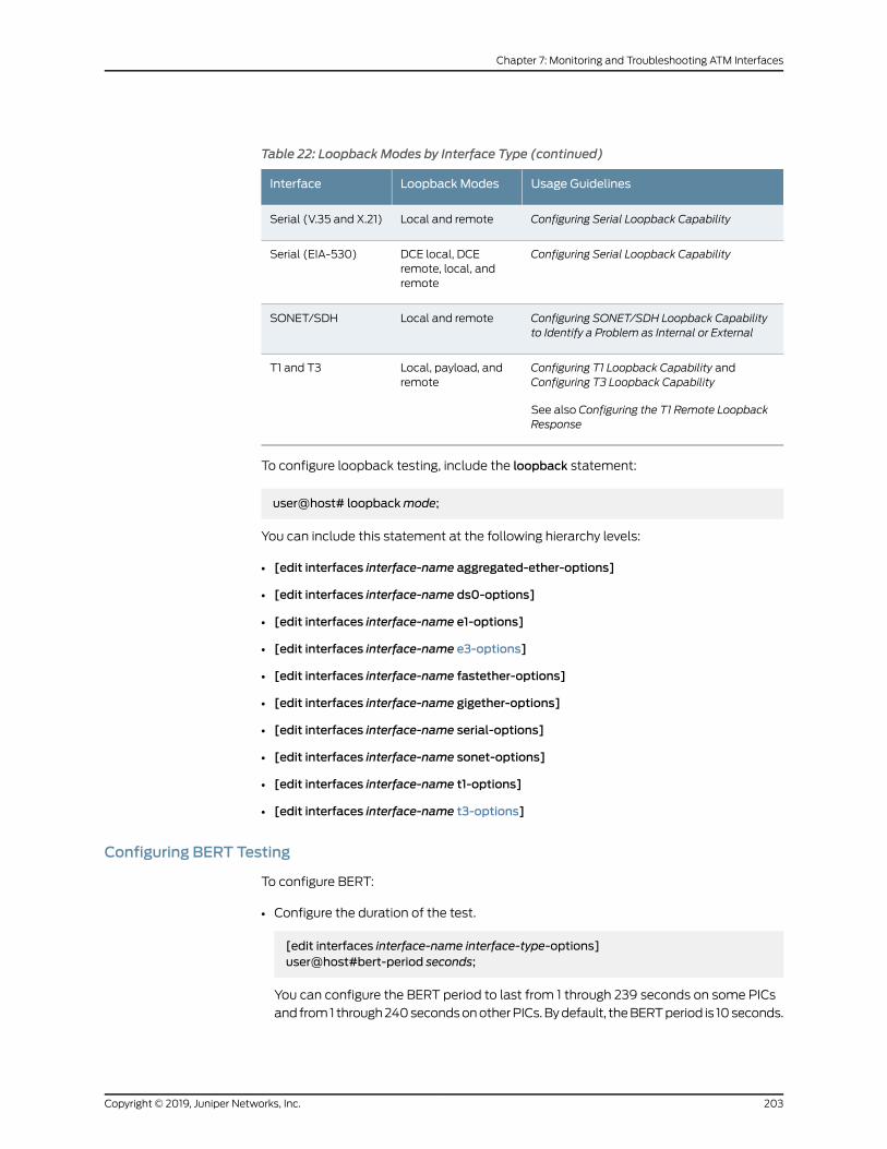
Table 22: Loopback Modes by Interface Type (continued)
Usage GuidelinesLoopback ModesInterface
Configuring Serial Loopback CapabilityLocal and remoteSerial (V.35 and X.21)
Configuring Serial Loopback CapabilityDCE local, DCEremote, local, andremote
Serial (EIA-530)
Configuring SONET/SDH Loopback Capabilityto Identify a Problem as Internal or External
Local and remoteSONET/SDH
Configuring T1 Loopback Capability andConfiguring T3 Loopback Capability
See also Configuring the T1 Remote LoopbackResponse
Local, payload, andremote
T1 and T3
To configure loopback testing, include the loopback statement:
user@host# loopbackmode;
You can include this statement at the following hierarchy levels:
• [edit interfaces interface-name aggregated-ether-options]
• [edit interfaces interface-name ds0-options]
• [edit interfaces interface-name e1-options]
• [edit interfaces interface-name e3-options]
• [edit interfaces interface-name fastether-options]
• [edit interfaces interface-name gigether-options]
• [edit interfaces interface-name serial-options]
• [edit interfaces interface-name sonet-options]
• [edit interfaces interface-name t1-options]
• [edit interfaces interface-name t3-options]
Configuring BERT Testing
To configure BERT:
• Configure the duration of the test.
[edit interfaces interface-name interface-type-options]user@host#bert-period seconds;
You can configure the BERT period to last from 1 through 239 seconds on some PICs
and from1 through240secondsonotherPICs.Bydefault, theBERTperiod is 10seconds.
203Copyright © 2019, Juniper Networks, Inc.
Chapter 7: Monitoring and Troubleshooting ATM Interfaces

• Configure the error rate to monitor when the inbound pattern is received.
[edit interfaces interface-name interface-type-options]user@host#bert-error-rate rate;
rate is the bit error rate. This can be an integer from 0 through 7, which corresponds to
a bit error rate from 10–0(1 error per bit) to 10
–7(1 error per 10 million bits).
• Configure the bit pattern to send on the transmit path.
[edit interfaces interface-name interface-type-options]user@host#bert-algorithm algorithm;
algorithm is the pattern to send in the bit stream. For a list of supported algorithms,
enter a ? after the bert-algorithm statement; for example:
[edit interfaces t1-0/0/0 t1-options]
user@host# set bert-algorithm ?
Possible completions: pseudo-2e11-o152 Pattern is 2^11 -1 (per O.152 standard) pseudo-2e15-o151 Pattern is 2^15 - 1 (per O.152 standard) pseudo-2e20-o151 Pattern is 2^20 - 1 (per O.151 standard) pseudo-2e20-o153 Pattern is 2^20 - 1 (per O.153 standard) ...
For specific hierarchy information, see the individual interface types.
NOTE: The four-port E1 PIC supports only the following algorithms:
pseudo-2e11-o152 Pattern is 2^11 -1 (per O.152 standard) pseudo-2e15-o151 Pattern is 2^15 - 1 (per O.151 standard) pseudo-2e20-o151 Pattern is 2^20 - 1 (per O.151 standard) pseudo-2e23-o151 Pattern is 2^23 (per O.151 standard)
When you issue the help command from the CLI, all BERT algorithm options
are displayed, regardless of the PIC type, and no commit check is available.Unsupported patterns for a PIC type can be viewed in system logmessages.
Copyright © 2019, Juniper Networks, Inc.204
ATM Interfaces Feature Guide for Routing Devices
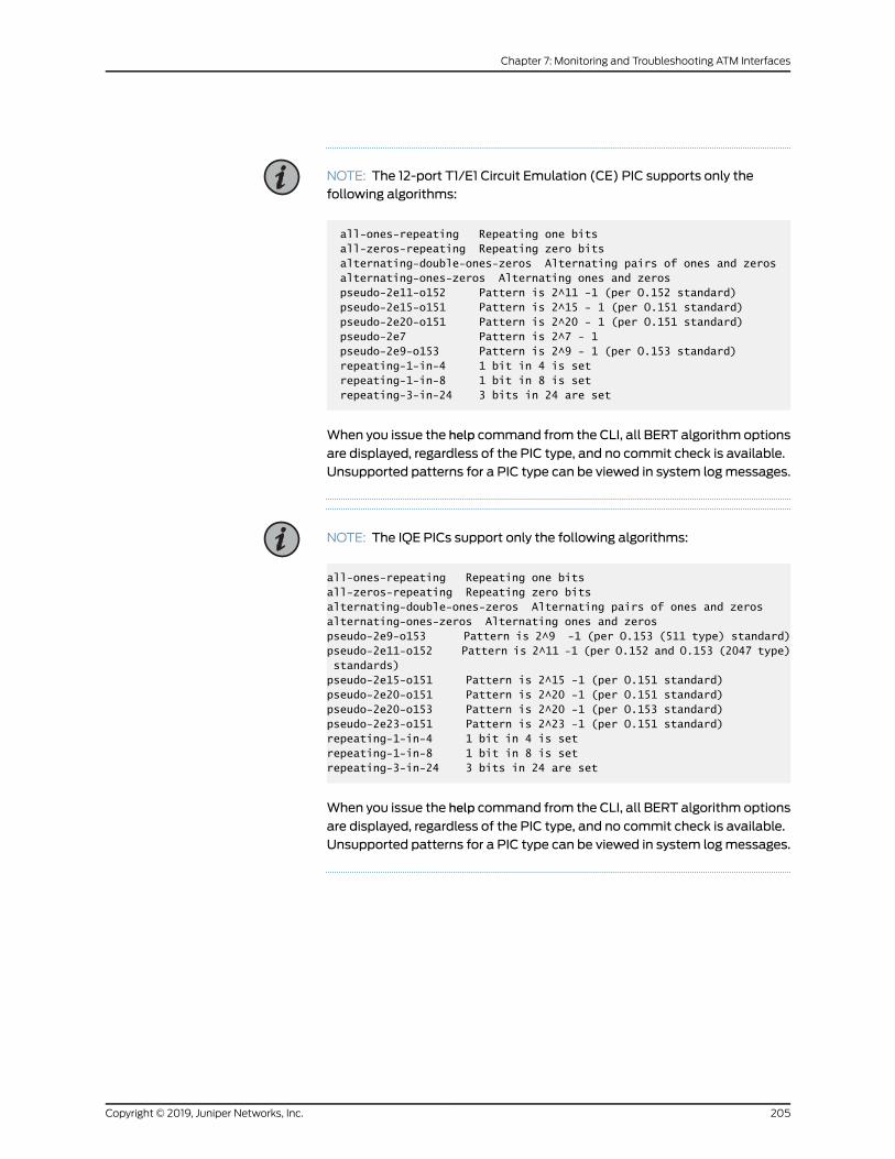
NOTE: The 12-port T1/E1 Circuit Emulation (CE) PIC supports only thefollowing algorithms:
all-ones-repeating Repeating one bits all-zeros-repeating Repeating zero bits alternating-double-ones-zeros Alternating pairs of ones and zeros alternating-ones-zeros Alternating ones and zeros pseudo-2e11-o152 Pattern is 2^11 -1 (per O.152 standard) pseudo-2e15-o151 Pattern is 2^15 - 1 (per O.151 standard) pseudo-2e20-o151 Pattern is 2^20 - 1 (per O.151 standard) pseudo-2e7 Pattern is 2^7 - 1 pseudo-2e9-o153 Pattern is 2^9 - 1 (per O.153 standard) repeating-1-in-4 1 bit in 4 is set repeating-1-in-8 1 bit in 8 is set repeating-3-in-24 3 bits in 24 are set
When you issue the help command from the CLI, all BERT algorithm options
are displayed, regardless of the PIC type, and no commit check is available.Unsupported patterns for a PIC type can be viewed in system logmessages.
NOTE: The IQE PICs support only the following algorithms:
all-ones-repeating Repeating one bitsall-zeros-repeating Repeating zero bitsalternating-double-ones-zeros Alternating pairs of ones and zerosalternating-ones-zeros Alternating ones and zerospseudo-2e9-o153 Pattern is 2^9 -1 (per O.153 (511 type) standard)pseudo-2e11-o152 Pattern is 2^11 -1 (per O.152 and O.153 (2047 type) standards)pseudo-2e15-o151 Pattern is 2^15 -1 (per O.151 standard)pseudo-2e20-o151 Pattern is 2^20 -1 (per O.151 standard)pseudo-2e20-o153 Pattern is 2^20 -1 (per O.153 standard)pseudo-2e23-o151 Pattern is 2^23 -1 (per O.151 standard)repeating-1-in-4 1 bit in 4 is setrepeating-1-in-8 1 bit in 8 is setrepeating-3-in-24 3 bits in 24 are set
When you issue the help command from the CLI, all BERT algorithm options
are displayed, regardless of the PIC type, and no commit check is available.Unsupported patterns for a PIC type can be viewed in system logmessages.
205Copyright © 2019, Juniper Networks, Inc.
Chapter 7: Monitoring and Troubleshooting ATM Interfaces
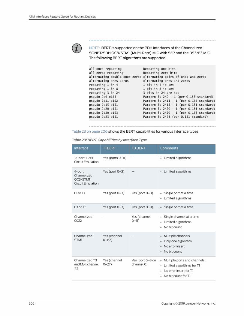
NOTE: BERT is supported on the PDH interfaces of the ChannelizedSONET/SDHOC3/STM1 (Multi-Rate) MIC with SFP and the DS3/E3MIC.The following BERT algorithms are supported:
all-ones-repeating Repeating one bitsall-zeros-repeating Repeating zero bitsalternating-double-ones-zeros Alternating pairs of ones and zerosalternating-ones-zeros Alternating ones and zerosrepeating-1-in-4 1 bit in 4 is setrepeating-1-in-8 1 bit in 8 is setrepeating-3-in-24 3 bits in 24 are setpseudo-2e9-o153 Pattern is 2^9 - 1 (per O.153 standard)pseudo-2e11-o152 Pattern is 2^11 - 1 (per O.152 standard)pseudo-2e15-o151 Pattern is 2^15 - 1 (per O.151 standard)pseudo-2e20-o151 Pattern is 2^20 - 1 (per O.151 standard)pseudo-2e20-o153 Pattern is 2^20 - 1 (per O.153 standard)pseudo-2e23-o151 Pattern is 2^23 (per O.151 standard)
Table 23 on page 206 shows the BERT capabilities for various interface types.
Table 23: BERT Capabilities by Interface Type
CommentsT3 BERTT1 BERTInterface
• Limited algorithms—Yes (ports 0–11)12-port T1/E1CircuitEmulation
• Limited algorithms—Yes (port 0–3)4-portChannelizedOC3/STM1CircuitEmulation
• Single port at a time
• Limited algorithms
Yes (port 0–3)Yes (port 0–3)E1 or T1
• Single port at a timeYes (port 0–3)Yes (port 0–3)E3 or T3
• Single channel at a time
• Limited algorithms
• No bit count
Yes (channel0–11)
—ChannelizedOC12
• Multiple channels
• Only one algorithm
• No error insert
• No bit count
—Yes (channel0–62)
ChannelizedSTM1
• Multiple ports and channels
• Limited algorithms for T1
• No error insert for T1
• No bit count for T1
Yes (port 0–3 onchannel 0)
Yes (channel0–27)
Channelized T3andMultichannelT3
Copyright © 2019, Juniper Networks, Inc.206
ATM Interfaces Feature Guide for Routing Devices
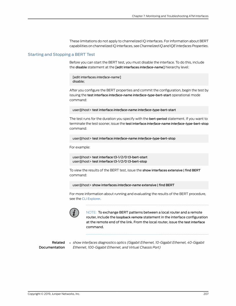
These limitations do not apply to channelized IQ interfaces. For information about BERT
capabilities onchannelized IQ interfaces, seeChannelized IQand IQE InterfacesProperties.
Starting and Stopping a BERT Test
Before you can start the BERT test, youmust disable the interface. To do this, include
the disable statement at the [edit interfaces interface-name] hierarchy level:
[edit interfaces interface-name]disable;
After you configure the BERT properties and commit the configuration, begin the test by
issuing the test interface interface-name interface-type-bert-start operational mode
command:
user@host> test interface interface-name interface-type-bert-start
The test runs for the duration you specify with the bert-period statement. If you want to
terminate the test sooner, issue the test interface interface-name interface-type-bert-stop
command:
user@host> test interface interface-name interface-type-bert-stop
For example:
user@host> test interface t3-1/2/0 t3-bert-startuser@host> test interface t3-1/2/0 t3-bert-stop
To view the results of the BERT test, issue the show interfaces extensive | find BERT
command:
user@host> show interfaces interface-name extensive | find BERT
For more information about running and evaluating the results of the BERT procedure,
see the CLI Explorer.
NOTE: To exchange BERT patterns between a local router and a remoterouter, include the loopback remote statement in the interface configuration
at the remote end of the link. From the local router, issue the test interface
command.
RelatedDocumentation
show interfaces diagnostics optics (Gigabit Ethernet, 10-Gigabit Ethernet, 40-Gigabit
Ethernet, 100-Gigabit Ethernet, and Virtual Chassis Port)
•
207Copyright © 2019, Juniper Networks, Inc.
Chapter 7: Monitoring and Troubleshooting ATM Interfaces

Investigating Interface Steps and Commands for ATM Interfaces
This section includes the following information to assist you when troubleshooting ATM
interfaces:
The “Monitoring ATM Interfaces” on page 178 section helps you determine the nature of
the interface problem. The “Using Loopback Testing for ATM Interfaces” on page 208
section provides information to help you isolate the source of the problem. The “Locating
ATM Alarms and Errors” on page 224 section explains some of the alarms and errors for
the media.
RelatedDocumentation
Monitoring ATM Interfaces on page 178•
• Using Loopback Testing for ATM Interfaces on page 208
• Locating ATM Alarms and Errors on page 224
Using Loopback Testing for ATM Interfaces
• Checklist for Using Loopback Testing for ATM Interfaces on page 208
• Diagnosing a Suspected Hardware Problemwith an ATM1 or ATM2 IQ
Interface on page 210
• Creating a Loopback on page 210
• Setting Clocking to Internal on page 213
• Verifying That the ATM Interface Is Up on page 214
• Clearing ATM Interface Statistics on page 217
• Pinging the ATM Interface on page 217
• Checking for ATM Interface Error Statistics on page 218
• Diagnosing a Suspected Circuit Problem on page 222
Checklist for Using Loopback Testing for ATM Interfaces
Purpose To use loopback testing for ATM interfaces.
Action Table 24 on page 208 provides links and commands for using loopback testing for ATM
interfaces.
Table 24: Checklist for Using Loopback Testing for ATM Interfaces
Command or ActionTasks
“Diagnosing a Suspected Hardware Problemwith an ATM1 or ATM2 IQ Interface” on page 210
1. Creating a Loopback on page 210
Connect the transmit port to the receive port.a. Creating a Physical Loopback on page 211
Copyright © 2019, Juniper Networks, Inc.208
ATM Interfaces Feature Guide for Routing Devices

Table 24: Checklist for Using Loopback Testing for ATM Interfaces (continued)
Command or ActionTasks
[edit interfaces interface-name (sonet-options |t3-options)]set loopback localshowcommit
b. Configuring a Local Loopback on page 211
[edit interfaces interface-name]set clocking internalshowcommit
2. Setting Clocking to Internal on page 213
show interfaces at-fpc/port/pic3. Verifying That the ATM Interface Is Up on page 214
clear interfaces statistics at-fpc/port/pic4. Clearing ATM Interface Statistics on page 217
ping interface at-fpc/port/pic local-IP-addressbypass-routing count 1000 rapid
5. Pinging the ATM Interface on page 217
show interfaces at-fpc/port/pic extensive6. Checking for ATM Interface Error Statistics on page 218
“Diagnosing a Suspected Circuit Problem” on page 222
[edit interfaces interface-name (sonet-options |t3-options)]set loopback remoteshowcommit
1. Creating a Loop from the Router to the Network on page 223
Perform Steps 2 through 6 from “Diagnosing aSuspectedHardwareProblemwithanATM1orATM2IQ Interface” on page 210.
2. Creating a Loop to the Router from Various Points in the Network onpage 224
See Also Diagnosing a Suspected Hardware Problemwith an ATM1 or ATM2 IQ Interface on
page 210
•
• Creating a Loopback on page 210
• Setting Clocking to Internal on page 213
• Verifying That the ATM Interface Is Up on page 214
• Clearing ATM Interface Statistics on page 217
• Pinging the ATM Interface on page 217
• Checking for ATM Interface Error Statistics on page 218
• Diagnosing a Suspected Circuit Problem on page 222
209Copyright © 2019, Juniper Networks, Inc.
Chapter 7: Monitoring and Troubleshooting ATM Interfaces

Diagnosing a Suspected Hardware Problemwith an ATM1 or ATM2 IQ Interface
Problem Description:When you suspect a hardware problem, perform the following steps to
verify if there is a hardware problem.
Solution To diagnose a suspected hardware problemwith an ATM1 or ATM2 IQ interface, follow
these steps:
1. Creating a Loopback on page 210
2. Setting Clocking to Internal on page 213
3. Verifying That the ATM Interface Is Up on page 214
4. Clearing ATM Interface Statistics on page 217
5. Pinging the ATM Interface on page 217
6. Checking for ATM Interface Error Statistics on page 218
See Also Checklist for Using Loopback Testing for ATM Interfaces on page 208•
• Creating a Loopback on page 210
• Setting Clocking to Internal on page 213
• Verifying That the ATM Interface Is Up on page 214
• Clearing ATM Interface Statistics on page 217
• Pinging the ATM Interface on page 217
• Checking for ATM Interface Error Statistics on page 218
• Diagnosing a Suspected Circuit Problem on page 222
Creating a Loopback
You can create a physical loopback or configure a local loopback to help diagnose a
suspected hardware problem. Creating a physical loopback is recommended because
it allows you to test and verify the transmit and receive ports.
If a field engineer is not available to create the physical loopback, you can configure a
local loopback for the interface. The local loopback creates a loopback internally in the
Physical Interface Card (PIC).
• Creating a Physical Loopback on page 211
• Configuring a Local Loopback on page 211
Copyright © 2019, Juniper Networks, Inc.210
ATM Interfaces Feature Guide for Routing Devices

Creating a Physical Loopback
Create a physical loopback from the transmit port to the receive port.
NOTE: Make sure you use single-mode fiber for a single-mode port andmultimode fiber for amultimode port for SONETmedia.
1. To create a physical loopback at the port, connect the transmit port to the receive
port using a known good cable.
When you create and test a physical loopback, you are testing the transmit and receive
ports of the PIC. This action is recommended if a field engineer is available to create the
physical loop as it provides amore complete test of the PIC.
See Also ATM Interfaces Feature Guide for Routing Devices•
Configuring a Local Loopback
Purpose Because ATM interfaces can be either SONET or T3, you use the sonet-options ort3-options statements to configure a local loopback. Figure 5 on page 211 illustrates alocal loopback configured for an ATM interface.
Figure 5: Local Loopback
Action To configure a local loopback without physically connecting the transmit port to thereceive port, follow these steps:
1. In configuration mode, go to the following hierarchy level:
[edit]user@host# edit interfaces interface-name (sonet-options | t3-options)
2. Configure the loopback:
[edit interfaces interface-name (sonet-options | t3-options)]user@host# set loopback local
3. Verify the configuration:
211Copyright © 2019, Juniper Networks, Inc.
Chapter 7: Monitoring and Troubleshooting ATM Interfaces

user@host# show
For example:
[edit interfaces (t3-1/0/0 t3-options)]user@host# showloopback local;
4. Commit the change:
user@host# commit
For example:
[edit interfaces t3-1/0/0 t3-options]user@host# commitcommit complete
Meaning When you create a local loopback, you create an internal loop on the interface beingtested. A local loopback loops the traffic internally on that PIC. A local loopback teststhe interconnection of the PIC but does not test the transmit and receive ports.
NOTE: Remember to delete the loopback statement after completing thetest.
See Also ATM Interfaces Feature Guide for Routing Devices•
See Also Checklist for Using Loopback Testing for ATM Interfaces on page 208•
• Diagnosing a Suspected Hardware Problemwith an ATM1 or ATM2 IQ Interface on
page 210
• Setting Clocking to Internal on page 213
• Verifying That the ATM Interface Is Up on page 214
• Clearing ATM Interface Statistics on page 217
• Pinging the ATM Interface on page 217
• Checking for ATM Interface Error Statistics on page 218
• Diagnosing a Suspected Circuit Problem on page 222
Copyright © 2019, Juniper Networks, Inc.212
ATM Interfaces Feature Guide for Routing Devices

Setting Clocking to Internal
Purpose Clocking is set to internal because there is no external clock source in a loopbackconnection.
Action To configure clocking to internal, follow these steps:
1. In configuration mode, go to the following hierarchy level:
[edit]user@host# edit interfaces interface-name
2. Configure the clocking to internal:
user@host# set clocking internal
3. Verify the configuration:
user@host# show
For example:
[edit interfaces t3-1/0/0]user@host# showclocking internal;
4. Commit the change:
user@host# commit
For example:
[edit interfaces t3-1/0/0]user@host# commitcommit complete
Meaning The clock source for the interface is set to the internal Stratum 3 clock.
See Also Checklist for Using Loopback Testing for ATM Interfaces on page 208•
• Diagnosing a Suspected Hardware Problemwith an ATM1 or ATM2 IQ Interface on
page 210
• Creating a Loopback on page 210
• Verifying That the ATM Interface Is Up on page 214
213Copyright © 2019, Juniper Networks, Inc.
Chapter 7: Monitoring and Troubleshooting ATM Interfaces

• Clearing ATM Interface Statistics on page 217
• Pinging the ATM Interface on page 217
• Checking for ATM Interface Error Statistics on page 218
• Diagnosing a Suspected Circuit Problem on page 222
Verifying That the ATM Interface Is Up
Purpose Displaying the statusof theATM interfaceprovides the information youneed todetermine
whether the physical link is up or down.
Action To verify that the status of the ATM interface is up, use the following Junos OS CLI
operational mode command:
user@host> show interfaces at-fpc/pic/port
Sample Output 1
The following sample output is for an OC3 ATM interface:
user@host> show interfaces at-2/0/0Physical interface: at-2/0/0, Enabled, Physical link is Up Interface index: 22, SNMP ifIndex: 42 Link-level type: ATM-PVC, MTU: 4482, Clocking: Internal, SONET mode, Speed: OC3 , Loopback: Local, Payload scrambler: EnabledDevice flags : Present Running
Link flags : None Input rate : 0 bps (0 pps) Output rate : 0 bps (0 pps)SONET alarms : NoneSONET defects : None
Logical interface at-2/0/0.0 (Index 29) (SNMP ifIndex 49) Flags: Point-To-Point SNMP-Traps Encapsulation: ATM-SNAP Input packets : 0 Output packets: 0 Protocol inet, MTU: 4470, Flags: None Addresses, Flags: Is-Preferred Is-Primary Destination: 192.168.1.0/30, Local: 192.168.1.1 VCI 1.100 Flags: Active Total down time: 0 sec, Last down: Never Traffic statistics: Input packets: 0 Output packets: 0
Sample Output 2
The following sample output is for a T3 ATM interface:
user@host> show interfaces at-0/1/0Physical interface: at-0/1/0, Enabled, Physical link is Up Interface index: 90, SNMP ifIndex: 18
Copyright © 2019, Juniper Networks, Inc.214
ATM Interfaces Feature Guide for Routing Devices
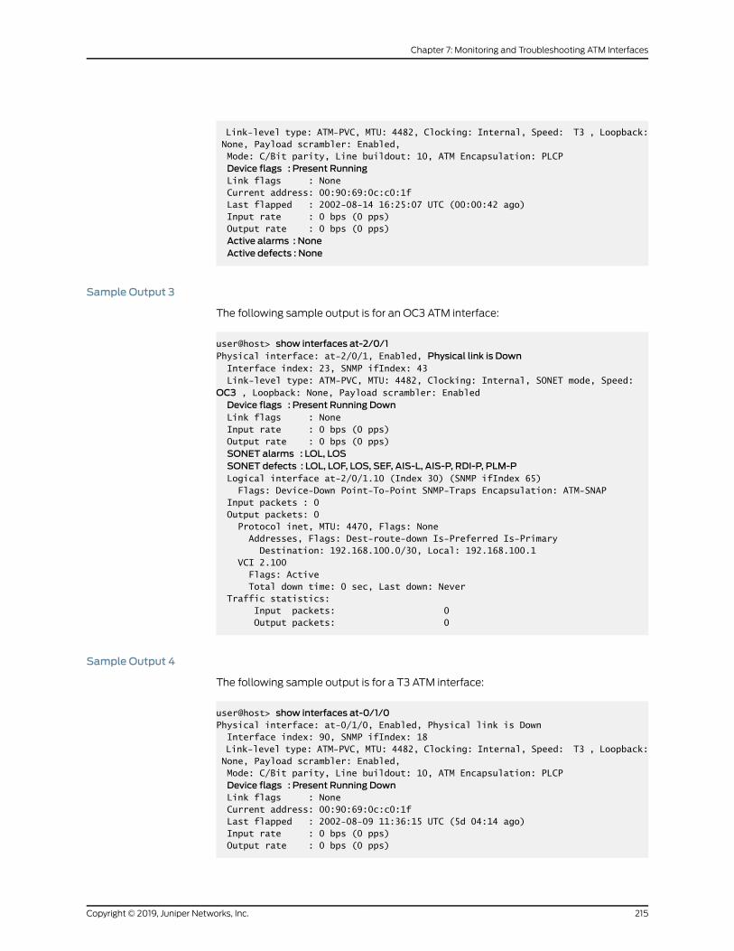
Link-level type: ATM-PVC, MTU: 4482, Clocking: Internal, Speed: T3 , Loopback: None, Payload scrambler: Enabled, Mode: C/Bit parity, Line buildout: 10, ATM Encapsulation: PLCPDevice flags : Present Running
Link flags : None Current address: 00:90:69:0c:c0:1f Last flapped : 2002-08-14 16:25:07 UTC (00:00:42 ago) Input rate : 0 bps (0 pps) Output rate : 0 bps (0 pps)Active alarms : NoneActive defects : None
Sample Output 3
The following sample output is for an OC3 ATM interface:
user@host> show interfaces at-2/0/1Physical interface: at-2/0/1, Enabled, Physical link is Down Interface index: 23, SNMP ifIndex: 43 Link-level type: ATM-PVC, MTU: 4482, Clocking: Internal, SONET mode, Speed: OC3 , Loopback: None, Payload scrambler: EnabledDevice flags : Present Running Down
Link flags : None Input rate : 0 bps (0 pps) Output rate : 0 bps (0 pps)SONET alarms : LOL, LOSSONET defects : LOL, LOF, LOS, SEF, AIS-L, AIS-P, RDI-P, PLM-P
Logical interface at-2/0/1.10 (Index 30) (SNMP ifIndex 65) Flags: Device-Down Point-To-Point SNMP-Traps Encapsulation: ATM-SNAP Input packets : 0 Output packets: 0 Protocol inet, MTU: 4470, Flags: None Addresses, Flags: Dest-route-down Is-Preferred Is-Primary Destination: 192.168.100.0/30, Local: 192.168.100.1 VCI 2.100 Flags: Active Total down time: 0 sec, Last down: Never Traffic statistics: Input packets: 0 Output packets: 0
Sample Output 4
The following sample output is for a T3 ATM interface:
user@host> show interfaces at-0/1/0Physical interface: at-0/1/0, Enabled, Physical link is Down Interface index: 90, SNMP ifIndex: 18 Link-level type: ATM-PVC, MTU: 4482, Clocking: Internal, Speed: T3 , Loopback: None, Payload scrambler: Enabled, Mode: C/Bit parity, Line buildout: 10, ATM Encapsulation: PLCPDevice flags : Present Running Down
Link flags : None Current address: 00:90:69:0c:c0:1f Last flapped : 2002-08-09 11:36:15 UTC (5d 04:14 ago) Input rate : 0 bps (0 pps) Output rate : 0 bps (0 pps)
215Copyright © 2019, Juniper Networks, Inc.
Chapter 7: Monitoring and Troubleshooting ATM Interfaces

Active alarms : PLL, LOF, LOSActive defects : PLL, LOF, LOS
Meaning Sample output 1 shows that the physical link is up and there are no SONET alarms or
defects.
Sample output 2 shows that the physical link is up and there are no active alarms or
defects.
Sample output 3 shows that the physical link, the device flags, and interface flags are
down, and that there are SONET alarms and defects. When you see that the physical
link is down, there may be a problemwith the port.
Sample output 4 shows that the physical link, the device flags, and interface flags are
down, and that there are active alarms and defects. When you see that the physical link
is down, there may be a problemwith the port.
For more information about problem situations and actions to take for a physical link
that is down, see Table 25 on page 216.
Table 25: Problems and Solutions for a Physical Link That Is Down
ActionsProblem
Verify that the cable connection is correct.Cable mismatch
Verify that the cable can successfully loop a known goodport of the same type.
Damaged fiber or coax cable or dirtyfiber cable
Verify that the attenuation is correct per the PIC opticalspecification.
Toomuch or too little opticalattenuation (for anOC3orOC12ATMinterface)
Verify that the Tx power of the optics is within range ofthe PIC optical specification.
The transmit port is not transmittingwithin the dBm optical range per thespecifications (for an OC3 or OC12ATM interface)
See Also Checklist for Using Loopback Testing for ATM Interfaces on page 208•
• Diagnosing a Suspected Hardware Problemwith an ATM1 or ATM2 IQ Interface on
page 210
• Creating a Loopback on page 210
• Setting Clocking to Internal on page 213
• Clearing ATM Interface Statistics on page 217
• Pinging the ATM Interface on page 217
• Checking for ATM Interface Error Statistics on page 218
Copyright © 2019, Juniper Networks, Inc.216
ATM Interfaces Feature Guide for Routing Devices

• Diagnosing a Suspected Circuit Problem on page 222
Clearing ATM Interface Statistics
Purpose Youmust reset ATM interface statistics before you initiate the ping test. Resetting thestatisticsprovidesacleanstart so thatprevious inputoroutputerrorsandpacket statisticsdo not interfere with the current investigation.
Action To clear all statistics for the interface, use the following Junos OS CLI operational modecommand:
user@host> clear interfaces statistics at-fpc/pic/port
Sample Output user@host> clear interfaces statistics at-4/0/2user@host>
Meaning This command clears the interface statistics counters for interface at-4/0/2 only.
See Also Checklist for Using Loopback Testing for ATM Interfaces on page 208•
• Diagnosing a Suspected Hardware Problemwith an ATM1 or ATM2 IQ Interface on
page 210
• Creating a Loopback on page 210
• Setting Clocking to Internal on page 213
• Verifying That the ATM Interface Is Up on page 214
• Pinging the ATM Interface on page 217
• Checking for ATM Interface Error Statistics on page 218
• Diagnosing a Suspected Circuit Problem on page 222
Pinging the ATM Interface
Purpose After you have put the port in a local loopback, run the ping test using the following Junos
OS CLI operational mode command:
Action user@host> ping interface at-fpc/pic/port-IP-address bypass-routing count 1000 rapid
Sample Output
user@host> ping interface at-2/0/0.0 192.168.1.1 bypass-routing count 1000 rapid
217Copyright © 2019, Juniper Networks, Inc.
Chapter 7: Monitoring and Troubleshooting ATM Interfaces
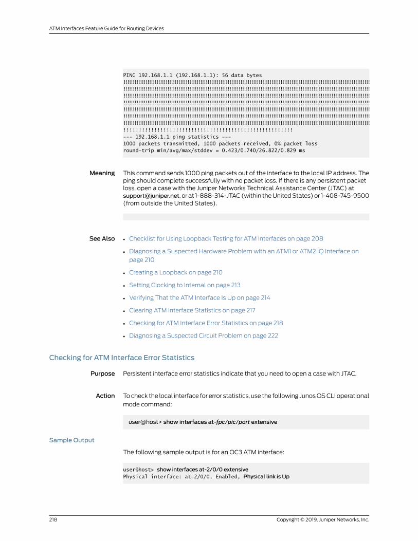
PING 192.168.1.1 (192.168.1.1): 56 data bytes!!!!!!!!!!!!!!!!!!!!!!!!!!!!!!!!!!!!!!!!!!!!!!!!!!!!!!!!!!!!!!!!!!!!!!!!!!!!!!!!!!!!!!!!!!!!!!!!!!!!!!!!!!!!!!!!!!!!!!!!!!!!!!!!!!!!!!!!!!!!!!!!!!!!!!!!!!!!!!!!!!!!!!!!!!!!!!!!!!!!!!!!!!!!!!!!!!!!!!!!!!!!!!!!!!!!!!!!!!!!!!!!!!!!!!!!!!!!!!!!!!!!!!!!!!!!!!!!!!!!!!!!!!!!!!!!!!!!!!!!!!!!!!!!!!!!!!!!!!!!!!!!!!!!!!!!!!!!!!!!!!!!!!!!!!!!!!!!!!!!!!!!!!!!!!!!!!!!!!!!!!!!!!!!!!!!!!!!!!!!!!!!!!!!!!!!!!!!!!!!!!!!!!!!!!!!!!!!!!!!!!!!!!!!!!!!!!!!!!!!!!!!!!!!!!!!!!!!!!!!!!!!!!!!!!!!!!!!!!!!!!!!!!!!!!!!!!!!!!!!!!!!!!!!!!!!!!!!!!!!!!!!!!!!!!!!!!!!!!!!!!!!!!!!!!!!!!!!!!!!!!!!!!!!!!!!!!!!!!!!!!!!!!!!!!!!!!!!!!!!!!!!!!!!!!!!!!!!!!!!!!!!!!!!!!!!!!!!!!!!!!!!!!!!!!!!!!!!!!!!!!!!!!!!!!!!!!!!!!!!!!!!!!!!!!!!!!!!!!!!!!!!!!!!!!!!!!!!!!!!!!!!!!!!!!!!!!!!!!!!!!!!!!!!!!!!!!!!!!!!!!!!!!!!!!!!!!!!!!!!!!!!!!!!!!!!!!!!!!!!!!!!!!!!!!!!!!!!!!!!!!!!!!!!!!!!!!!!!!!!!!!!!!!!!!!!!!!!!!!!!!!!!!!!!!!!!!!!!!!!!!!!!!!!!!!!!!!!!!!!!!!!!!!!!!!!!!!!!!!!!!!!!!!!!!!!!!!!!!!!!!!!!!!!!!!!!!!!!!!!!!!!!!!!!!!!!!!!!!!!!!!!!!!!!!!!!!!!!!!!--- 192.168.1.1 ping statistics ---1000 packets transmitted, 1000 packets received, 0% packet lossround-trip min/avg/max/stddev = 0.423/0.740/26.822/0.829 ms
Meaning This command sends 1000 ping packets out of the interface to the local IP address. Theping should complete successfully with no packet loss. If there is any persistent packetloss, open a case with the Juniper Networks Technical Assistance Center (JTAC) [email protected], or at 1-888-314-JTAC(within theUnitedStates)or 1-408-745-9500(from outside the United States).
See Also Checklist for Using Loopback Testing for ATM Interfaces on page 208•
• Diagnosing a Suspected Hardware Problemwith an ATM1 or ATM2 IQ Interface on
page 210
• Creating a Loopback on page 210
• Setting Clocking to Internal on page 213
• Verifying That the ATM Interface Is Up on page 214
• Clearing ATM Interface Statistics on page 217
• Checking for ATM Interface Error Statistics on page 218
• Diagnosing a Suspected Circuit Problem on page 222
Checking for ATM Interface Error Statistics
Purpose Persistent interface error statistics indicate that you need to open a case with JTAC.
Action Tocheck the local interface for error statistics, use the following JunosOSCLI operational
mode command:
user@host> show interfaces at-fpc/pic/port extensive
Sample Output
The following sample output is for an OC3 ATM interface:
user@host> show interfaces at-2/0/0 extensivePhysical interface: at-2/0/0, Enabled, Physical link is Up
Copyright © 2019, Juniper Networks, Inc.218
ATM Interfaces Feature Guide for Routing Devices

Interface index: 22, SNMP ifIndex: 42, Generation: 21 Link-level type: ATM-PVC, MTU: 4482, Clocking: Internal, SONET mode, Speed: OC3 , Loopback: None, Payload scrambler: Enabled Device flags : Present Running Link flags : None Hold-times : Up 0 ms, Down 0 ms Statistics last cleared: 2002-07-29 14:28:14 EDT (00:00:26 ago) Traffic statistics: Input bytes : 0 0 bps Output bytes : 0 0 bps Input packets: 0 0 pps Output packets: 0 0 pps Input errors: Errors: 0, Drops: 0, Invalid VCs: 0, Framing errors: 0, Policed discards: 0, L3 incompletes: 0, L2 channel errors: 0, L2 mismatch timeouts: 0 Output errors: Carrier transitions: 0, Errors: 0, Drops: 0, Aged packets: 0 SONET alarms : None SONET defects : None SONET PHY: Seconds Count State PLL Lock 0 0 OK PHY Light 0 0 OK SONET section: BIP-B1 0 0 SEF 0 0 OK LOS 0 0 OK LOF 0 0 OK ES-S 0 SES-S 0 SEFS-S 0 SONET line: BIP-B2 0 0 REI-L 0 0 RDI-L 0 0 OK AIS-L 0 0 OK BERR-SF 0 0 OK BERR-SD 0 0 OK ES-L 0 SES-L 0 UAS-L 0 ES-LFE 0 SES-LFE 0 UAS-LFE 0 SONET path: BIP-B3 0 0 REI-P 0 0 LOP-P 0 0 OK AIS-P 0 0 OK RDI-P 0 0 OK UNEQ-P 0 0 OK PLM-P 0 0 OK ES-P 0 SES-P 0 UAS-P 0 ES-PFE 0 SES-PFE 0 UAS-PFE 0 Received SONET overhead: F1 : 0x00, J0 : 0x00, K1 : 0x00, K2 : 0x00
219Copyright © 2019, Juniper Networks, Inc.
Chapter 7: Monitoring and Troubleshooting ATM Interfaces

S1 : 0x00, C2 : 0x13, C2(cmp) : 0x13, F2 : 0x00 Z3 : 0x00, Z4 : 0x00, S1(cmp) : 0x00, V5 : 0x00 V5(cmp) : 0x00 Transmitted SONET overhead: F1 : 0x00, J0 : 0x01, K1 : 0x00, K2 : 0x00 S1 : 0x00, C2 : 0x13, F2 : 0x00, Z3 : 0x00 Z4 : 0x00, V5 : 0x00 ATM status: HCS state: Sync LOC : OK ATM Statistics: Uncorrectable HCS errors: 0, Correctable HCS errors: 0, Tx cell FIFO overruns: 0, Rx cell FIFO overruns: 0, Rx cell FIFO underruns: 0, Input cell count: 0, Output cell count: 8830024, Output idle cell count: 8830026, Output VC queue drops: 0, Input no buffers: 0, Input length errors: 0, Input timeouts: 0, Input invalid VCs: 0, Input bad CRCs: 0, Input OAM cell no buffers: 0 PFE configuration: Destination slot: 2 CoS transmit queue Bandwidth Buffer Priority Limit % bps % bytes 0 best-effort 0 0 0 0 low none 1 expedited-forwarding 0 0 0 0 low none 2 assured-forwarding 0 0 0 0 low none 3 network-control 0 0 0 0 low none Logical interface at-2/0/0.0 (Index 29) (SNMP ifIndex 49) (Generation 28) Flags: Point-To-Point SNMP-Traps Encapsulation: ATM-SNAP Traffic statistics: Input bytes : 0 Output bytes : 0 Input packets: 0 Output packets: 0 Local statistics: Input bytes : 0 Output bytes : 0 Input packets: 0 Output packets: 0 Transit statistics: Input bytes : 0 0 bps Output bytes : 0 0 bps Input packets: 0 0 pps Output packets: 0 0 pps Protocol inet, MTU: 4470, Flags: None, Generation: 31 Route table: 0 Addresses, Flags: Is-Preferred Is-Primary Destination: 192.168.1.0/30, Local: 192.168.1.1, Broadcast: Unspecified, Generation: 59 VCI 1.100 Flags: Active Total down time: 0 sec, Last down: Never ATM per-VC transmit statistics: Tail queue packet drops: 0 Traffic statistics: Input bytes : 0 Output bytes : 0 Input packets: 0 Output packets: 0
Copyright © 2019, Juniper Networks, Inc.220
ATM Interfaces Feature Guide for Routing Devices

Sample Output
The following sample output is for a T3 ATM interface:
user@host> show interfaces at-0/1/0 extensivePhysical interface: at-0/1/0, Enabled, Physical link is Up Interface index: 90, SNMP ifIndex: 18, Generation: 89 Link-level type: ATM-PVC, MTU: 4482, Clocking: Internal, Speed: T3 , Loopback: None, Payload scrambler: Enabled, Mode: C/Bit parity, Line buildout: 10, ATM Encapsulation: PLCP Device flags : Present Running Link flags : None Hold-times : Up 0 ms, Down 0 ms Current address: 00:90:69:0c:c0:1f Last flapped : 2002-08-14 16:25:07 UTC (00:00:21 ago) Statistics last cleared: 2002-08-14 16:25:26 UTC (00:00:02 ago) Traffic statistics: Input bytes : 0 0 bps Output bytes : 0 0 bps Input packets: 0 0 pps Output packets: 0 0 pps Input errors: Errors: 0, Drops: 0, Invalid VCs: 0, Framing errors: 0, Policed discards: 0, L3 incompletes: 0, L2 channel errors: 0, L2 mismatch timeouts: 0 Output errors: Carrier transitions: 0, Errors: 0, Drops: 0, Aged packets: 0 Active alarms : None Active defects : None DS3 media: Seconds Count State PLL Lock 0 0 OK Reframing 0 0 OK AIS 0 0 OK LOF 0 0 OK LOS 0 0 OK YELLOW 0 0 OK EXZ 0 0 LCV 0 0 PCV 0 0 FERR 0 0 LES 0 PES 0 PSES 0 SEFS 0 UAS 0 PLCP defects: Seconds Count State LOF 0 0 YELLOW 0 0 ATM defects: Seconds Count State LCD 0 0 ATM status: HCS state: Sync LOC : OK PLCP statistics (errored seconds): Framing errors : 0(0) Bit interleaved parity errors: 0(0) Far end block errors : 0(0) ATM Statistics: Uncorrectable HCS errors: 0, Correctable HCS errors: 0, Tx cell FIFO overruns: 0, Rx cell FIFO overruns: 0,
221Copyright © 2019, Juniper Networks, Inc.
Chapter 7: Monitoring and Troubleshooting ATM Interfaces

Rx cell FIFO underruns: 0, Input cell count: 0, Output cell count: 96041, Output idle cell count: 96040, Output VC queue drops: 0, Input no buffers: 0, Input length errors: 0, Input timeouts: 0, Input invalid VCs: 0, Input bad CRCs: 0, Input OAM cell no buffers: 0 Packet Forwarding Engine configuration: Destination slot: 0 CoS transmit queue Bandwidth Buffer Priority Limit % bps % bytes 0 best-effort 95 42499200 95 0 low none 3 network-control 5 2236800 5 0 low none
Meaning
Check for any error statistics that may appear in the output. There should not be any
input or output errors. If there are any persistent input or output errors, open a case with
the JTAC at [email protected], or at 1-888-314-JTAC (within the United States) or
1-408-745-9500 (from outside the United States).
See Also Checklist for Using Loopback Testing for ATM Interfaces on page 208•
• Diagnosing a Suspected Hardware Problemwith an ATM1 or ATM2 IQ Interface on
page 210
• Creating a Loopback on page 210
• Setting Clocking to Internal on page 213
• Verifying That the ATM Interface Is Up on page 214
• Clearing ATM Interface Statistics on page 217
• Pinging the ATM Interface on page 217
• Diagnosing a Suspected Circuit Problem on page 222
Diagnosing a Suspected Circuit Problem
When you suspect a circuit problem, it is important to work with the transport-layer
engineer to resolve the problem. The transport-layer engineer may ask you to create a
loop from the router to the network, or the engineer may create a loop to the router from
various points in the network.
To diagnose a suspected circuit problem, follow these steps:
1. Creating a Loop from the Router to the Network on page 223
2. Creating a Loop to the Router from Various Points in the Network on page 224
Copyright © 2019, Juniper Networks, Inc.222
ATM Interfaces Feature Guide for Routing Devices

Creating a Loop from the Router to the Network
Purpose
Creating a loop from the router to the network allows the transport-layer engineer to
test the router from various points in the network. This helps the engineer isolate where
the problemmight be located. Figure 6 on page 223 illustrates a loop froma router to the
network.
Figure 6: Loop from the Router to the Network
Action
To create a loop from the router to the network, follow these steps:
1. In configuration mode, go to the following hierarchy level:
[edit]user@host# edit interfaces interface-name (sonet-options | t3-options)
2. Configure the remote loopback:
[edit interfaces interface-name (sonet-options | t3-options)]user@host# set loopback remote
3. Verify the configuration:
user@host# show
For example:
[edit interfaces t3-1/0/0 t3-options]user@host# showloopback remote;
4. Commit the change:
user@host# commit
For example:
[edit interfaces t3-1/0/0 t3-options]user@host# commitcommit complete
223Copyright © 2019, Juniper Networks, Inc.
Chapter 7: Monitoring and Troubleshooting ATM Interfaces

See Also Creating a Loop to the Router from Various Points in the Network on page 224•
Creating a Loop to the Router fromVarious Points in the Network
Purpose The transport-layer engineer creates a loop to the router from various points in thenetwork. You can then perform tests to verify the connection from the router to thatloopback in the network.
Action After the transport-layer engineer has created the loop to the router from the network,youmust verify the connection from the router to the loopback in the network. FollowSteps 2 through 6 in “Diagnosing a Suspected Hardware Problemwith an ATM1 or ATM2IQ Interface”onpage210.Keep inmind thatanyproblemsencountered in the test indicatea problemwith the connection from the router to the loopback in the network.
By performing tests to loopbacks at various points in the network, you can isolate the
source of the problem.
See Also Creating a Loop from the Router to the Network on page 223•
See Also Checklist for Using Loopback Testing for ATM Interfaces on page 208•
• Diagnosing a Suspected Hardware Problemwith an ATM1 or ATM2 IQ Interface on
page 210
• Creating a Loopback on page 210
• Setting Clocking to Internal on page 213
• Verifying That the ATM Interface Is Up on page 214
• Clearing ATM Interface Statistics on page 217
• Pinging the ATM Interface on page 217
• Checking for ATM Interface Error Statistics on page 218
RelatedDocumentation
Investigating Interface Steps and Commands•
• Determining ATM Interface Type on page 165
• Monitoring ATM Interfaces on page 178
• Locating ATM Alarms and Errors on page 224
Locating ATMAlarms and Errors
• List of Common ATM Alarms and Error on page 225
• Displaying ATM1 and ATM2 Alarms and Errors on page 225
Copyright © 2019, Juniper Networks, Inc.224
ATM Interfaces Feature Guide for Routing Devices
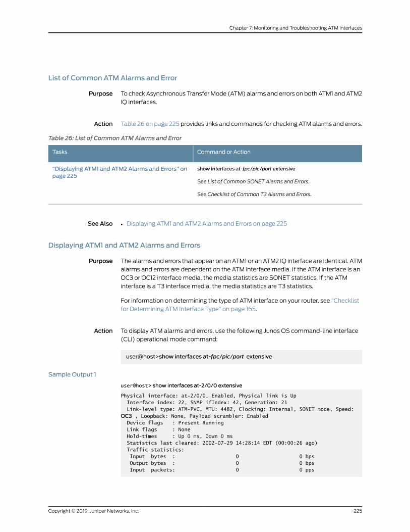
List of Common ATMAlarms and Error
Purpose To check Asynchronous TransferMode (ATM) alarms and errors on both ATM1 andATM2
IQ interfaces.
Action Table 26 on page 225 provides links and commands for checking ATMalarms and errors.
Table 26: List of Common ATMAlarms and Error
Command or ActionTasks
show interfaces at-fpc/pic/port extensive
See List of Common SONET Alarms and Errors.
See Checklist of Common T3 Alarms and Errors.
“Displaying ATM1 and ATM2 Alarms and Errors” onpage 225
See Also Displaying ATM1 and ATM2 Alarms and Errors on page 225•
Displaying ATM1 and ATM2 Alarms and Errors
Purpose The alarms and errors that appear on anATM1 or an ATM2 IQ interface are identical. ATM
alarms and errors are dependent on the ATM interface media. If the ATM interface is an
OC3 or OC12 interface media, the media statistics are SONET statistics. If the ATM
interface is a T3 interface media, the media statistics are T3 statistics.
For information on determining the type of ATM interface on your router, see “Checklist
for Determining ATM Interface Type” on page 165.
Action To display ATM alarms and errors, use the following Junos OS command-line interface
(CLI) operational mode command:
user@host>show interfaces at-fpc/pic/port extensive
Sample Output 1
user@host> show interfaces at-2/0/0 extensive
Physical interface: at-2/0/0, Enabled, Physical link is Up Interface index: 22, SNMP ifIndex: 42, Generation: 21 Link-level type: ATM-PVC, MTU: 4482, Clocking: Internal, SONET mode, Speed: OC3 , Loopback: None, Payload scrambler: Enabled Device flags : Present Running Link flags : None Hold-times : Up 0 ms, Down 0 ms Statistics last cleared: 2002-07-29 14:28:14 EDT (00:00:26 ago) Traffic statistics: Input bytes : 0 0 bps Output bytes : 0 0 bps Input packets: 0 0 pps
225Copyright © 2019, Juniper Networks, Inc.
Chapter 7: Monitoring and Troubleshooting ATM Interfaces

Output packets: 0 0 pps Input errors: Errors: 0, Drops: 0, Invalid VCs: 0, Framing errors: 0, Policed discards: 0, L3 incompletes: 0, L2 channel errors: 0, L2 mismatch timeouts: 0 Output errors: Carrier transitions: 0, Errors: 0, Drops: 0, Aged packets: 0 SONET alarms : None SONET defects : None SONET PHY: Seconds Count State PLL Lock 0 0 OK PHY Light 0 0 OKSONET section:
BIP-B1 0 0 SEF 0 0 OK LOS 0 0 OK LOF 0 0 OK ES-S 0 SES-S 0 SEFS-S 0SONET line:
BIP-B2 0 0 REI-L 0 0 RDI-L 0 0 OK AIS-L 0 0 OK BERR-SF 0 0 OK BERR-SD 0 0 OK ES-L 0 SES-L 0 UAS-L 0 ES-LFE 0 SES-LFE 0 UAS-LFE 0SONET path:
BIP-B3 0 0 REI-P 0 0 LOP-P 0 0 OK AIS-P 0 0 OK RDI-P 0 0 OK UNEQ-P 0 0 OK PLM-P 0 0 OK ES-P 0 SES-P 0 UAS-P 0 ES-PFE 0 SES-PFE 0 UAS-PFE 0 Received SONET overhead: F1 : 0x00, J0 : 0x00, K1 : 0x00, K2 : 0x00 S1 : 0x00, C2 : 0x13, C2(cmp) : 0x13, F2 : 0x00 Z3 : 0x00, Z4 : 0x00, S1(cmp) : 0x00, V5 : 0x00 V5(cmp) : 0x00 Transmitted SONET overhead: F1 : 0x00, J0 : 0x01, K1 : 0x00, K2 : 0x00 S1 : 0x00, C2 : 0x13, F2 : 0x00, Z3 : 0x00 Z4 : 0x00, V5 : 0x00 ATM status: HCS state: Sync LOC : OK ATM Statistics:
Copyright © 2019, Juniper Networks, Inc.226
ATM Interfaces Feature Guide for Routing Devices
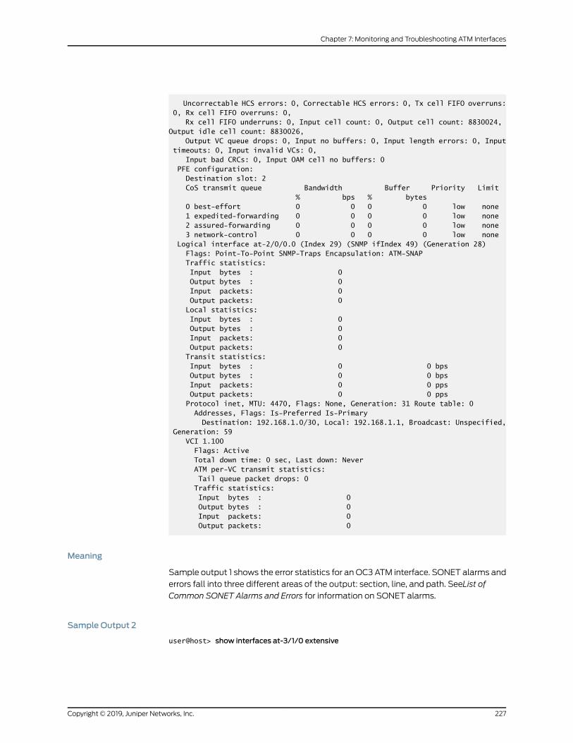
Uncorrectable HCS errors: 0, Correctable HCS errors: 0, Tx cell FIFO overruns: 0, Rx cell FIFO overruns: 0, Rx cell FIFO underruns: 0, Input cell count: 0, Output cell count: 8830024, Output idle cell count: 8830026, Output VC queue drops: 0, Input no buffers: 0, Input length errors: 0, Input timeouts: 0, Input invalid VCs: 0, Input bad CRCs: 0, Input OAM cell no buffers: 0 PFE configuration: Destination slot: 2 CoS transmit queue Bandwidth Buffer Priority Limit % bps % bytes 0 best-effort 0 0 0 0 low none 1 expedited-forwarding 0 0 0 0 low none 2 assured-forwarding 0 0 0 0 low none 3 network-control 0 0 0 0 low none Logical interface at-2/0/0.0 (Index 29) (SNMP ifIndex 49) (Generation 28) Flags: Point-To-Point SNMP-Traps Encapsulation: ATM-SNAP Traffic statistics: Input bytes : 0 Output bytes : 0 Input packets: 0 Output packets: 0 Local statistics: Input bytes : 0 Output bytes : 0 Input packets: 0 Output packets: 0 Transit statistics: Input bytes : 0 0 bps Output bytes : 0 0 bps Input packets: 0 0 pps Output packets: 0 0 pps Protocol inet, MTU: 4470, Flags: None, Generation: 31 Route table: 0 Addresses, Flags: Is-Preferred Is-Primary Destination: 192.168.1.0/30, Local: 192.168.1.1, Broadcast: Unspecified, Generation: 59 VCI 1.100 Flags: Active Total down time: 0 sec, Last down: Never ATM per-VC transmit statistics: Tail queue packet drops: 0 Traffic statistics: Input bytes : 0 Output bytes : 0 Input packets: 0 Output packets: 0
Meaning
Sample output 1 shows the error statistics for an OC3 ATM interface. SONET alarms and
errors fall into three different areas of the output: section, line, and path. SeeList of
Common SONET Alarms and Errors for information on SONET alarms.
Sample Output 2
user@host> show interfaces at-3/1/0 extensive
227Copyright © 2019, Juniper Networks, Inc.
Chapter 7: Monitoring and Troubleshooting ATM Interfaces

Physical interface: at-3/1/0, Enabled, Physical link is Up Interface index: 57, SNMP ifIndex: 66, Generation: 56 Description: customer Link-level type: ATM-PVC, MTU: 4482, Clocking: Internal, Speed: T3 , Loopback: None, Payload scrambler: Disabled, Mode: C/Bit parity, Line build-out: 10, ATM Encapsulation: PLCP Device flags : Present Running Link flags : None Hold-times : Up 0 ms, Down 0 ms Statistics last cleared: 2002-07-30 15:36:58 UTC (00:00:02 ago) Traffic statistics: Input bytes : 270798 1067704 bps Output bytes : 2260295 8911952 bps Input packets: 2001 986 pps Output packets: 2506 1235 pps Input errors: Errors: 0, Drops: 0, Invalid VCs: 0, Framing errors: 0, Policed discards: 0, L3 incompletes: 0, L2 channel errors: 0, L2 mismatch timeouts: 0 Output errors: Carrier transitions: 0, Errors: 0, Drops: 0, Aged packets: 0Active alarms : None
Active defects : NoneDS3media : Seconds Count State
PLL Lock 0 0 OK Reframing 0 0 OK AIS 0 0 OK LOF 0 0 OK LOS 0 0 OK YELLOW 0 0 OK EXZ 0 0 LCV 0 0 PCV 0 0 FERR 0 0 LES 0 PES 0 PSES 0 SEFS 0 UAS 0 PLCP defects: Seconds Count State LOF 0 0 YELLOW 0 0 ATM defects: Seconds Count State LCD 0 0 ATM status: HCS state: Hunt LOC : OK PLCP statistics (errored seconds): Framing errors : 0(0) Bit interleaved parity errors: 0(0) Far end block errors : 0(0) ATM Statistics: Uncorrectable HCS errors: 0, Correctable HCS errors: 0, Tx cell FIFO overruns: 0, Rx cell FIFO overruns: 0, Rx cell FIFO underruns: 0, Input cell count: 7716,
Output cell count: 191980, Output idle cell count: 144302, Output VC queue drops: 0, Input no buffers: 0, Input length errors: 0, Input timeouts: 0, Input invalid
Copyright © 2019, Juniper Networks, Inc.228
ATM Interfaces Feature Guide for Routing Devices

VCs: 0, Input bad CRCs: 0, Input OAM cell no buffers: 0 PFE configuration: Destination slot: 3 CoS transmit queue Bandwidth Buffer Priority Limit % bps % bytes 0 best-effort 0 0 0 0 low none 1 expedited-forwarding 0 0 0 0 low none 2 assured-forwarding 0 0 0 0 low none 3 network-control 0 0 0 0 low none Logical interface at-3/1/0.0 (Index 25) (SNMP ifIndex 85) (Generation 44) Flags: Point-To-Point Inverse-ARP SNMP-Traps Encapsulation: ATM-SNAP Traffic statistics: Input bytes : 270798 Output bytes : 2260295 Input packets: 2001 Output packets: 2506 Local statistics: Input bytes : 0 Output bytes : 0 Input packets: 0 Output packets: 0 Transit statistics: Input bytes : 270798 1067704 bps Output bytes : 2260295 8911952 bps Input packets: 2001 986 pps Output packets: 2506 1235 pps Protocol inet, MTU: 4470, Flags: None, Generation: 51 Route table: 0 Addresses, Flags: Is-Preferred Is-Primary Destination: 10.10.65.176/30, Local: 10.10.65.177, Broadcast: Unspecified, Generation: 88 VCI 0.5 Flags: Active, Inverse-ARP Total down time: 0 sec, Last down: Never ATM per-VC transmit statistics: Tail queue packet drops: 0 Traffic statistics: Input bytes : 270798 Output bytes : 2260295 Input packets: 2001 Output packets: 2506
Meaning
Sample output 2 shows the error statistics for a T3 ATM interface. See Checklist of
Common T3 Alarms and Errors for information on T3 alarms.
Table 27 on page 229 describes the input and output errors that appear in the extensive
output for an ATM interface.
Table 27: ATM Interface Input and Output Errors
Reason for ErrorDescriptionError
Input Errors
Sumof the incoming frame aborts and framecheck sequence (FCS) errors.
Errors
229Copyright © 2019, Juniper Networks, Inc.
Chapter 7: Monitoring and Troubleshooting ATM Interfaces

Table 27: ATM Interface Input and Output Errors (continued)
Reason for ErrorDescriptionError
If the interface is saturated, this number incrementsonce for every packet that is dropped by the ASIC’srandom early detection (RED)mechanism.
Number of packets dropped by the outputqueue of the I/O Manager ASIC.
Drops
Number of cells that arrived for a nonexistentvirtual circuit (VC).
Invalid VCs
SumofATMAdaptationLayer (AAL5)packetsthat have FCS errors, AAL5 packets that havereassembly timeout errors, andAAL5packetsthat have length errors.
Framing errors
Usually, this field reports protocols that the Junos OSdoes not handle.
Frames that the incoming packetmatch codediscarded because they were not recognizedor of interest.
Policed discards
Increments when the incoming packet fails Layer 3(usually IPv4) sanity checksof theheader. For example,a frame with less than 20 bytes of available IP headerwould be discarded and this counter would increment.
Number of packets discarded due to thepackets failing Layer 3 header checks.
L3 incompletes
This counter incrementswhen thesoftwarecannot finda valid logical interface for an incoming frame.
Errors that occurredwhen the software couldnot find a valid logical interface for anincoming frame.
L2 channel errors
Count of malformed or short packets that cause theincoming packet handler to discard the frame asunreadable.
Count of malformed or short packets.L2mismatchtimeouts
Output Errors
This number should not increment quickly and shouldincrease only when the cable is unplugged, the far-endsystem is powered down and up, or a similar problemoccurs. If it increments quickly (perhaps once every10 seconds), then the cable, the far-end system, or thePhysical Interface Card (PIC) is broken.
Number of times the interface went fromdown to up.
Carrier transitions
Sum of the outgoing frame aborts and FCSerrors.
Errors
If the interface is saturated, this number incrementsonce for everypacket that is droppedby theASIC’sREDmechanism.
Number of packets dropped by the outputqueue of the I/O Manager ASIC.
Drops
The value in this field should never increment. If it does,it is most likely a software bug or possibly brokenhardware.
Number of packets that remained in sharedpacket SDRAM for so long that the systemautomatically purged them.
Aged packets
Table 28 on page 231 lists ATMmedia-specific alarms and defects that can render the
interface unable to pass packets. When a defect persists for a certain amount of time,
Copyright © 2019, Juniper Networks, Inc.230
ATM Interfaces Feature Guide for Routing Devices
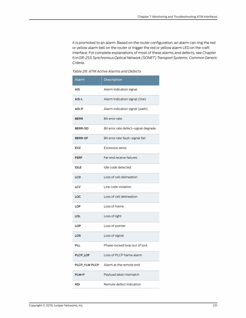
it is promoted to an alarm. Based on the router configuration, an alarm can ring the red
or yellow alarm bell on the router or trigger the red or yellow alarm LED on the craft
interface. For complete explanations of most of these alarms and defects, see Chapter
6 inGR-253, SynchronousOpticalNetwork (SONET)TransportSystems: CommonGeneric
Criteria.
Table 28: ATMActive Alarms and Defects
DescriptionAlarm
Alarm indication signalAIS
Alarm indication signal (line)AIS-L
Alarm indication signal (path)AIS-P
Bit error rateBERR
Bit error rate defect–signal degradeBERR-SD
Bit error rate fault–signal failBERR-SF
Excessive zerosEXZ
Far end receive failuresFERF
Idle code detectedIDLE
Loss of cell delineationLCD
Line code violationLCV
Loss of cell delineationLOC
Loss of frameLOF
Loss of lightLOL
Loss of pointerLOP
Loss of signalLOS
Phase-locked loop out of lockPLL
Loss of PLCP frame alarmPLCP_LOF
Alarm at the remote endPLCP_YLWPLCP
Payload label mismatchPLM-P
Remote defect indicationRDI
231Copyright © 2019, Juniper Networks, Inc.
Chapter 7: Monitoring and Troubleshooting ATM Interfaces

Table 28: ATMActive Alarms and Defects (continued)
DescriptionAlarm
Remote defect indication (line)RDI-L
Remote defect indication (path)RDI-P
Remote error indicationREI
Severely errored frameSEF
UnequippedUNEQ
Remote defect indication (yellowalarm)
YLW
See Also List of Common ATM Alarms and Error on page 225•
RelatedDocumentation
• Investigating Interface Steps and Commands
• Determining ATM Interface Type on page 165
• Monitoring ATM Interfaces on page 178
• Using Loopback Testing for ATM Interfaces on page 208
Copyright © 2019, Juniper Networks, Inc.232
ATM Interfaces Feature Guide for Routing Devices

PART 5
Configuration Statements andOperational Commands
• Configuration Statements on page 235
• Operational Commands on page 335
233Copyright © 2019, Juniper Networks, Inc.

Copyright © 2019, Juniper Networks, Inc.234
ATM Interfaces Feature Guide for Routing Devices
CHAPTER 8
Configuration Statements
• advertise-interval on page 237
• allow-any-vci on page 238
• annex on page 238
• aps on page 239
• atm-encapsulation on page 240
• atm-options on page 241
• atm-scheduler-map on page 242
• authentication-key on page 243
• buildout (E3 or T3 over ATM Interfaces) on page 244
• bytes on page 245
• cbit-parity on page 246
• cbr on page 247
• cell-bundle-size on page 248
• down-count on page 249
• e3-options on page 250
• encapsulation (Logical Interface) on page 251
• encapsulation on page 255
• epd-threshold (Logical Interface) on page 263
• epd-threshold (Physical Interface) on page 264
• family on page 265
• fast-aps-switch on page 270
• force on page 271
• forwarding-class (ATM2 IQ Scheduler Maps) on page 272
• framing (E1, E3, and T1 Interfaces) on page 273
• high-plp-max-threshold on page 274
• high-plp-threshold on page 275
• hold-time (APS) on page 276
• hold-time (SONET/SDH Defect Triggers) on page 277
235Copyright © 2019, Juniper Networks, Inc.

• ilmi on page 278
• inverse-arp on page 279
• linear-red-profile on page 280
• linear-red-profiles on page 281
• lockout on page 282
• loopback (ADSL, DS0, E1/E3, SONET/SDH, SHDSL, and T1/T3) on page 283
• low-plp-max-threshold on page 285
• low-plp-threshold on page 286
• maximum-vcs on page 287
• mpls (Interfaces) on page 288
• multicast-vci on page 289
• multipoint-destination on page 290
• neighbor (Automatic Protection Switching for SONET/SDH) on page 291
• oam-liveness on page 292
• oam-period on page 293
• paired-group on page 294
• passive-monitor-mode on page 295
• payload-scrambler on page 296
• pic-type on page 297
• plp1 on page 298
• plp-to-clp on page 299
• pop-all-labels on page 300
• priority (Schedulers) on page 301
• promiscuous-mode on page 302
• protect-circuit on page 303
• queue-depth on page 304
• queue-length on page 305
• receive-options-packets on page 306
• receive-ttl-exceeded on page 306
• request on page 307
• required-depth on page 308
• revert-time (Interfaces) on page 309
• rfc-2615 on page 309
• rtvbr on page 310
• scheduler-maps (For ATM2 IQ Interfaces) on page 311
• shaping on page 312
• t3-options on page 313
Copyright © 2019, Juniper Networks, Inc.236
ATM Interfaces Feature Guide for Routing Devices

• transmit-weight (ATM2 IQ CoS Forwarding Class) on page 314
• transmit-weight (ATM2 IQ Virtual Circuit) on page 315
• trigger on page 316
• trunk-bandwidth on page 317
• trunk-id on page 318
• unit on page 319
• use-null-cw on page 326
• up-count on page 327
• vbr on page 328
• vc-cos-mode on page 329
• vci on page 330
• vpi (ATM CCC Cell-Relay Promiscuous Mode) on page 331
• vpi (Define Virtual Path) on page 332
• vpi (Logical Interface and Interworking) on page 333
• working-circuit on page 333
• z0-increment on page 334
advertise-interval
Syntax advertise-intervalmilliseconds;
Hierarchy Level [edit interfaces interface-name sonet-options aps]
Release Information Statement introduced before Junos OS Release 7.4.
Description Modify the Automatic Protection Switching (APS) interval at which the protect and
working routers send packets to their neighbors to advertise that they are operational. A
router considers its neighbor to be operational for a period, called the hold time, that is,
by default, three times the advertisement interval.
Options milliseconds—Interval between advertisement packets.
Range: 1 through 65,534milliseconds
Default: 1000milliseconds
Required PrivilegeLevel
interface—To view this statement in the configuration.
interface-control—To add this statement to the configuration.
RelatedDocumentation
• Configuring APS Timers
237Copyright © 2019, Juniper Networks, Inc.
Chapter 8: Configuration Statements

allow-any-vci
Syntax allow-any-vci;
Hierarchy Level [edit interfaces interface-name unit 0],[edit logical-systems logical-system-name interfaces interface-name unit 0]
Release Information Statement introduced before Junos OS Release 7.4.
Statement introduced in JunosOSRelease 12.2 for theACXSeriesUniversalMetro routers.
Description Dedicate entire ATM device to ATM cell relay circuit.
Required PrivilegeLevel
interface—To view this statement in the configuration.
interface-control—To add this statement to the configuration.
RelatedDocumentation
• Configuring an ATM1 Cell-Relay Circuit Overview on page 80
annex
Syntax annex (annex-a | annex-b);
Hierarchy Level [edit interfaces interface-name shdsl-options],[edit interfaces interface-name sonet-options aps],[edit logical-systems logical-system-name interfaces interface-name shdsl-options]
Release Information Statement introduced in Junos OS Release 7.4.
Description For M320 and M120 routers only, for Multiplex Section Protection (MSP) switching on
SDH interfaces, set annex-b. Youmust also configure theworking protection circuit under
the [edit interfaces so-fpc/pic/port sonet-options aps] hierarchy level.
Default annex-b
Options annex-a—Use for North American SHDSL network implementations.
annex-b—Use for European SHDSL network implementations.
Required PrivilegeLevel
interface—To view this statement in the configuration.
interface-control—To add this statement to the configuration.
Copyright © 2019, Juniper Networks, Inc.238
ATM Interfaces Feature Guide for Routing Devices

aps
Syntax aps {advertise-intervalmilliseconds;annex-bauthentication-key key;(break-before-make | no-break-before-make);fast-aps-switch;force;hold-timemilliseconds;lockout;neighbor address;paired-group group-name;preserve-interface;protect-circuit group-name;request;revert-time seconds;switching-mode (bidirectional | unidirectional);working-circuit group-name;
}
Hierarchy Level [edit interfaces interface-name sonet-options]
Release Information Statement introduced before Junos OS Release 7.4.
Description Configure Automatic Protection Switching (APS) on the router.
For DS3 channels on a channelized OC12 interface, configure APS on channel 0 only. If
you configure APS on channels 1 through 11, it is ignored.
The remaining statements are explained separately. See CLI Explorer.
Required PrivilegeLevel
interface—To view this statement in the configuration.
interface-control—To add this statement to the configuration.
RelatedDocumentation
• Automatic Protection Switching and Multiplex Section Protection Overview
239Copyright © 2019, Juniper Networks, Inc.
Chapter 8: Configuration Statements

atm-encapsulation
Syntax atm-encapsulation (direct | plcp);
Hierarchy Level [edit interfaces at-fpc/pic/port e3-options],[edit interfaces at-fpc/pic/port t3-options]
Release Information Statement introduced before Junos OS Release 7.4.
Description Configure encapsulation for E3 and T3 traffic over ATM interfaces.
Default Physical Layer Convergence Protocol (PLCP) encapsulation is the default for T3 traffic
and for E3 traffic using G.751 framing.
Options direct—Use direct encapsulation. G.832 framing on E3 interfaces requires direct
encapsulation.
plcp—Use PLCP encapsulation.
Required PrivilegeLevel
interface—To view this statement in the configuration.
interface-control—To add this statement to the configuration.
RelatedDocumentation
• Configuring E3 and T3 Parameters on ATM Interfaces on page 49
• encapsulation on page 255
Copyright © 2019, Juniper Networks, Inc.240
ATM Interfaces Feature Guide for Routing Devices

atm-options
Syntax atm-options {cell-bundle-size cells;ilmi;linear-red-profiles profile-name {high-plp-max-threshold percent;low-plp-max-threshold percent;queue-depth cells high-plp-threshold percent low-plp-threshold percent;
}mpls {pop-all-labels {required-depth number;
}}pic-type (atm1 | atm2);plp-to-clp;promiscuous-mode {vpi vpi-identifier;
}scheduler-mapsmap-name {forwarding-class class-name {epd-threshold cells plp1 cells;linear-red-profile profile-name;priority (high | low);transmit-weight (cells number | percent number);
}vc-cos-mode (alternate | strict);
}use-null-cw;vpi vpi-identifier {maximum-vcsmaximum-vcs;oam-liveness {up-count cells;down-count cells;
}oam-period (disable | seconds);shaping {(cbr rate | rtvbrpeak rate sustained rateburst length | vbrpeak rate sustained rateburstlength);
queue-length number;}
}}
Hierarchy Level [edit interfaces interface-name]
Release Information Statement introduced before Junos OS Release 7.4.
Statement introduced in JunosOSRelease 12.2 for theACXSeriesUniversalMetroRouters.
Description Configure ATM-specific physical interface properties.
241Copyright © 2019, Juniper Networks, Inc.
Chapter 8: Configuration Statements

The remaining statementsareexplainedseparately. Search for a statement inCLIExplorer
or click a linked statement in the Syntax section for details.
NOTE: Certain options apply only to specific platforms.
Required PrivilegeLevel
interface—To view this statement in the configuration.
interface-control—To add this statement to the configuration.
RelatedDocumentation
• Interface Encapsulations Overview
• multipoint-destination on page 290
• shaping on page 312
• vci on page 330
atm-scheduler-map
Syntax atm-scheduler-map (map-name | default);
Hierarchy Level [edit interfaces interface-name unit logical-unit-number],[edit logical-systems logical-system-name interfaces interface-nameunit logical-unit-number]
Release Information Statement introduced before Junos OS Release 7.4.
Description Associate a scheduler map with a virtual circuit on a logical interface.
Options map-name—Nameof schedulermap that youdefineat the [edit interfaces interface-name
atm-options scheduler-maps] hierarchy level.
default—The default scheduler mapping.
Required PrivilegeLevel
interface—To view this statement in the configuration.
interface-control—To add this statement to the configuration.
RelatedDocumentation
• ATM2 IQ VC Tunnel CoS Components Overview on page 117
• scheduler-maps (For ATM2 IQ Interfaces) on page 311
Copyright © 2019, Juniper Networks, Inc.242
ATM Interfaces Feature Guide for Routing Devices

authentication-key
Syntax authentication-key key;
Hierarchy Level [edit interfaces interface-name sonet-options aps]
Release Information Statement introduced before Junos OS Release 7.4.
Description Configure the Automatic Protection Switching (APS) authentication key (password).
Options key—Authentication password. It can be 1 through 8 characters long. Configure the same
key for both the working and protect routers.
Required PrivilegeLevel
interface—To view this statement in the configuration.
interface-control—To add this statement to the configuration.
RelatedDocumentation
• Configuring Basic Automatic Protect Switching
• For information about the authentication-key statement at the [edit interfaces
interface-name unit unit-number family inet address address (vrrp-group |
vrrp-inet6-group)group-number]or [edit logical-systems logical-system-name interfaces
interface-name unit unit-number family (inet | inet6) address address (vrrp-group |
vrrp-inet6-group)group-number]hierarchy level, see theHighAvailability FeatureGuide.
243Copyright © 2019, Juniper Networks, Inc.
Chapter 8: Configuration Statements

buildout (E3 or T3 over ATM Interfaces)
Syntax buildout feet;
Hierarchy Level [edit interfaces at-fpc/pic/port e3-options],[edit interfaces at-fpc/pic/port t3-options]
Release Information Statement introduced before Junos OS Release 7.4.
Description For E3 and T3 traffic over ATM interfaces, set the buildout value.
Options feet—The buildout value in feet.
Range: 0 through 450 feet (137 meters)
Default: 10 feet (3 meters)
Required PrivilegeLevel
interface—To view this statement in the configuration.
interface-control—To add this statement to the configuration.
RelatedDocumentation
• Configuring E3 and T3 Parameters on ATM Interfaces on page 49
Copyright © 2019, Juniper Networks, Inc.244
ATM Interfaces Feature Guide for Routing Devices

bytes
Syntax bytes {c2 value;e1-quiet value;f1 value;f2 value;s1 value;z3 value;z4 value;
}
Hierarchy Level [edit interfaces interface-name sonet-options]
Release Information Statement introduced before Junos OS Release 7.4.
Description Set values in some SONET/SDH header bytes.
Options c2 value—Path signal label SONET/SDH overhead byte. SONET/SDH frames use the C2
byte to indicate thecontentsof thepayload inside the frame.SONET/SDH interfaces
use the C2 byte to indicate whether the payload is scrambled.
Range: 0 through 255
Default: 0xCF
e1-quiet value—Default idle byte sent on the orderwire SONET/SDH overhead bytes. The
router does not support the orderwire channel, and hence sends this byte
continuously.
Range: 0 through 255
Default: 0x7F
f1 value, f2 value, z3 value, z4 value—SONET/SDH overhead bytes.
Range: 0 through 255
Default: 0x00
s1value—SynchronizationmessageSONEToverheadbyte.Thisbyte isnormally controlled
as a side effect of the system reference clock configuration and the state of the
external clock coming from an interface if the system reference clocks have been
configured to use an external reference.
Range: 0 through 255
Default: 0xCC
Required PrivilegeLevel
interface—To view this statement in the configuration.
interface-control—To add this statement to the configuration.
245Copyright © 2019, Juniper Networks, Inc.
Chapter 8: Configuration Statements

RelatedDocumentation
• Configuring SONET/SDH Header Byte Values to Identify Error Conditions
• no-concatenate
cbit-parity
Syntax (cbit-parity | no-cbit-parity);
Hierarchy Level [edit interfaces interface-name t3-options]
Release Information Statement introduced before Junos OS Release 7.4.
Description For T3 interfaces only, enable or disable C-bit parity mode, which controls the type of
framing that is present on the transmitted T3 signal. When C-bit parity mode is enabled,
the C-bit positions are used for the far-end block error (FEBE), far-end alarmand control
(FEAC), terminal data link, path parity, andmode indicator bits, as defined in ANSI
T1.107a-1989. For ATM and ATM2 IQ2 and IQ2-E interfaces, M23 framing is used when
the no-cbit-parity statement is included. For all other interfaces, M13 framing is used
when the no-cbit-parity statement is included.
Default C-bit parity mode is enabled.
Required PrivilegeLevel
interface—To view this statement in the configuration.
interface-control—To add this statement to the configuration.
RelatedDocumentation
• Configuring E3 and T3 Parameters on ATM Interfaces on page 49
• Disabling T3 C-Bit Parity Mode
Copyright © 2019, Juniper Networks, Inc.246
ATM Interfaces Feature Guide for Routing Devices

cbr
Syntax cbr rate;
Hierarchy Level [edit interfaces at-fpc/pic/port atm-options vpi vpi-identifier shaping],[edit interfaces at-fpc/pic/port unit logical-unit-number address address family familymultipoint-destination address shaping],[edit interfaces at-fpc/pic/port unit logical-unit-number shaping],[edit logical-systems logical-system-name interfacesat-fpc/pic/portunit logical-unit-numberaddress address family familymultipoint-destination address shaping],
[edit logical-systems logical-system-name interfacesat-fpc/pic/portunit logical-unit-numbershaping]
Release Information Statement introduced before Junos OS Release 7.4.
Description For ATM encapsulation only, define a constant bit rate bandwidth utilization in the
traffic-shaping profile.
Default Unspecified bit rate (UBR); that is, bandwidth utilization is unlimited.
Options rate—Peak rate, in bits per second (bps) or cells per second (cps). You can specify avalue inbitsper secondeitherasacompletedecimalnumberorasadecimalnumber
followed by the abbreviation k (1000),m (1,000,000), or g (1,000,000,000). You
can also specify a value in cells per second by entering a decimal number followed
by the abbreviation c; values expressed in cells per second are converted to bits per
second bymeans of the formula 1 cps = 384 bps.
For ATM1 and ATM2 OC3 interfaces, the maximum available rate is 100 percent of
line-rate, or 135,600,000 bps. For ATM1 OC12 interfaces, the maximum available
rate is 50 percent of line-rate, or 271,263,396 bps. For ATM2 IQ interfaces, the
maximum available rate is 542,526,792 bps.
Required PrivilegeLevel
interface—To view this statement in the configuration.
interface-control—To add this statement to the configuration.
RelatedDocumentation
• Defining the ATM Traffic-Shaping Profile Overview on page 107
• rtvbr on page 310
• shaping on page 312
• vbr on page 328
247Copyright © 2019, Juniper Networks, Inc.
Chapter 8: Configuration Statements

cell-bundle-size
Syntax cell-bundle-size cells;
Hierarchy Level [edit interfaces at-fpc/pic/port atm-options],[edit interfaces at-fpc/pic/port unit logical-unit-number],[edit logical-systems logical-system-name interfacesat-fpc/pic/portunit logical-unit-number]
Release Information Statement introduced before Junos OS Release 7.4.
Description ForATM2 IQ interfaces usingATMLayer 2 circuit cell-relay transportmodeonly, configure
the maximum number of ATM cells per frame.
NOTE: For MIC-3D-8OC3-2OC12-ATM onMX104 routers, ensure that theconfigured cell-bundle-size is less than 30 for an ATM interface that is
configured with atm-ccc-cell-relay encapsulation. If the configured
cell-bundle-size is greater thanorequal to30and the traffic ispassing through
the interface at line rate, it might lead to AFEB crash.
Options cells—Maximum number of cells.
Default: 1 cell
Range: 1 through 176 cells
Required PrivilegeLevel
interface—To view this statement in the configuration.
interface-control—To add this statement to the configuration.
RelatedDocumentation
• Configuring the Layer 2 Circuit Cell-Relay Cell MaximumOverview on page 74
Copyright © 2019, Juniper Networks, Inc.248
ATM Interfaces Feature Guide for Routing Devices

down-count
Syntax down-count cells;
Hierarchy Level [edit interfaces interface-name atm-options vpi vpi-identifier oam-liveness],[edit interfaces interface-name unit logical-unit-number oam-liveness],[edit interfaces interface-name unit logical-unit-number family family address addressmultipoint-destination address oam-liveness],
[edit logical-systems logical-system-name interfaces interface-nameunit logical-unit-numberoam-liveness],
[edit logical-systems logical-system-name interfaces interface-nameunit logical-unit-numberfamily family address addressmultipoint-destination address oam-liveness]
Release Information Statement introduced before Junos OS Release 7.4.
Description For ATM encapsulation only, configure Operation, Administration, and Maintenance
(OAM) F5 loopback cell count thresholds. This feature is not supported on
ATM-over-SHDSL interfaces.
For ATM2 IQ PICs only, configure OAM F4 loopback cell count thresholds at the [edit
interfaces interface-name atm-options vpi vpi-identifier] hierarchy level.
Options cells—Minimum number of consecutive OAM F4 or F5 loopback cells lost before a VC is
declared down.
Range: 1 through 255
Default: 5 cells
Required PrivilegeLevel
interface—To view this statement in the configuration.
interface-control—To add this statement to the configuration.
RelatedDocumentation
• Configuring the ATMOAM F5 Loopback Cell Threshold on page 86
249Copyright © 2019, Juniper Networks, Inc.
Chapter 8: Configuration Statements

e3-options
Syntax e3-options {atm-encapsulation (direct | plcp);bert-algorithm algorithm;bert-error-rate rate;bert-period seconds;buildout feet;compatibility-mode (digital-link | kentrox | larscom) <subrate value>;fcs (16 | 32);framing (g.751 | g.832);idle-cycle-flag value;invert-data;loopback (local | remote);(payload-scrambler | no-payload-scrambler);start-end-flag value;(unframed | no-unframed);
}
Hierarchy Level [edit interfaces interface-name]
Release Information Statement introduced before Junos OS Release 7.4.
Description Configure E3-specific physical interface properties.
For ATM1 interfaces, you can configure a subset of E3 options statements.
The remaining statements are explained separately. See CLI Explorer.
Required PrivilegeLevel
interface—To view this statement in the configuration.
interface-control—To add this statement to the configuration.
RelatedDocumentation
• E3 Interfaces Overview
• T3 Interfaces Overview
• atm-options on page 241
Copyright © 2019, Juniper Networks, Inc.250
ATM Interfaces Feature Guide for Routing Devices

encapsulation (Logical Interface)
Syntax encapsulation (atm-ccc-cell-relay | atm-ccc-vc-mux | atm-cisco-nlpid | atm-mlppp-llc |atm-nlpid | atm-ppp-llc | atm-ppp-vc-mux | atm-snap | atm-tcc-snap | atm-tcc-vc-mux| atm-vc-mux | ether-over-atm-llc | ether-vpls-over-atm-llc | ether-vpls-over-fr |ether-vpls-over-ppp | ethernet | ethernet-ccc | ethernet-vpls | ethernet-vpls-fr |frame-relay-ccc | frame-relay-ether-type | frame-relay-ether-type-tcc | frame-relay-ppp| frame-relay-tcc | gre-fragmentation | multilink-frame-relay-end-to-end | multilink-ppp| ppp-over-ether | ppp-over-ether-over-atm-llc | vlan-bridge | vlan-ccc | vlan-vci-ccc |vlan-tcc | vlan-vpls | vxlan);
Hierarchy Level [edit interfaces interface-name unit logical-unit-number],[edit logical-systems logical-system-name interfaces interface-nameunit logical-unit-number],[edit interfaces rlsq number unit logical-unit-number][edit protocols evpn]
Release Information Statement introduced before Junos OS Release 7.4.
Statement introduced in Junos OS Release 12.1X48 for PTX Series Packet Transport
Routers (ethernet,vlan-ccc, and vlan-tcc options only).
Statement introduced in JunosOSRelease 12.2 for theACXSeriesUniversalMetroRouters.
Only the atm-ccc-cell-relay and atm-ccc-vc-mux options are supported on ACX Series
routers.
Statement introduced in Junos OS Release 17.3R1 for QFX10000 Series switches
(ethernet-ccc and vlan-ccc options only).
Description Configure a logical link-layer encapsulation type. Not all encapsulation types are
supported on the switches. See the switch CLI.
Options atm-ccc-cell-relay—Use ATM cell-relay encapsulation.
atm-ccc-vc-mux—Use ATM virtual circuit (VC) multiplex encapsulation on CCC circuits.
When you use this encapsulation type, you can configure the ccc family only.
atm-cisco-nlpid—UseCiscoATMnetwork layer protocol identifier (NLPID)encapsulation.
When you use this encapsulation type, you can configure the inet family only.
atm-mlppp-llc—For ATM2 IQ interfaces only, use Multilink Point-to-Point (MLPPP) over
AAL5 LLC. For this encapsulation type, your router must be equipped with a Link
Services or Voice Services PIC. MLPPP over ATM encapsulation is not supported on
ATM2 IQ OC48 interfaces.
atm-nlpid—Use ATMNLPID encapsulation. When you use this encapsulation type, you
can configure the inet family only.
atm-ppp-llc—(ATM2 IQ interfaces and MX Series routers with MPC/MIC interfaces using
the ATMMIC with SFP only) Use PPP over AAL5 LLC encapsulation.
251Copyright © 2019, Juniper Networks, Inc.
Chapter 8: Configuration Statements

atm-ppp-vc-mux—(ATM2 IQ interfaces and MX Series routers with MPC/MIC interfaces
using the ATMMICwith SFP only) Use PPPover ATMAAL5multiplex encapsulation.
atm-snap—(All interfaces including MX Series routers with MPC/MIC interfaces using
the ATMMIC with SFP) Use ATM subnetwork attachment point (SNAP)
encapsulation.
atm-tcc-snap—Use ATM SNAP encapsulation on translational cross-connect (TCC)
circuits.
atm-tcc-vc-mux—Use ATM VCmultiplex encapsulation on TCC circuits. When you use
this encapsulation type, you can configure the tcc family only.
atm-vc-mux—(All interfaces including MX Series routers with MPC/MIC interfaces using
the ATMMIC with SFP) Use ATM VCmultiplex encapsulation. When you use this
encapsulation type, you can configure the inet family only.
ether-over-atm-llc—(All IP interfaces includingMXSeries routerswithMPC/MIC interfaces
using the ATMMIC with SFP) For interfaces that carry IP traffic, use Ethernet over
ATMLLCencapsulation.Whenyouuse this encapsulation type, youcannotconfigure
multipoint interfaces.
ether-vpls-over-atm-llc—For ATM2 IQ interfaces only, use the Ethernet virtual private
LAN service (VPLS) over ATM LLC encapsulation to bridge Ethernet interfaces and
ATM interfacesover aVPLS routing instance (asdescribed inRFC2684,Multiprotocol
Encapsulation over ATM Adaptation Layer 5). Packets from the ATM interfaces are
converted to standard ENET2/802.3 encapsulated Ethernet frames with the frame
check sequence (FCS) field removed.
ether-vpls-over-fr—For E1, T1, E3, T3, and SONET interfaces only, use the Ethernet virtual
private LAN service (VPLS) over Frame Relay encapsulation to support Bridged
Ethernet over Frame Relay encapsulated TDM interfaces for VPLS applications, per
RFC 2427,Multiprotocol Interconnect over Frame Relay.
NOTE: The SONET/SDHOC3/STM1 (Multi-Rate) MIC with SFP, theChannelized SONET/SDHOC3/STM1 (Multi-Rate) MIC with SFP, and theDS3/E3MIC do not support Ethernet over Frame Relay encapsulation.
ether-vpls-over-ppp—For E1, T1, E3, T3, and SONET interfaces only, use the Ethernet
virtualprivateLANservice (VPLS)overPoint-to-PointProtocol (PPP)encapsulation
to support Bridged Ethernet over PPP-encapsulated TDM interfaces for VPLS
applications.
ethernet—Use Ethernet II encapsulation (as described in RFC 894, A Standard for the
Transmission of IP Datagrams over Ethernet Networks).
ethernet-ccc—Use Ethernet CCC encapsulation on Ethernet interfaces.
Copyright © 2019, Juniper Networks, Inc.252
ATM Interfaces Feature Guide for Routing Devices

ethernet-vpls—Use Ethernet VPLS encapsulation on Ethernet interfaces that have VPLS
enabled and that must accept packets carrying standard Tag Protocol ID (TPID)
values.
NOTE: The built-in Gigabit Ethernet PIC on anM7i router does not supportextended VLAN VPLS encapsulation.
ethernet-vpls-fr—Use in a VPLS setupwhen a CE device is connected to a PE router over
a time-division multiplexing (TDM) link. This encapsulation type enables the PE
router to terminate the outer layer 2 Frame Relay connection, use the 802.1p bits
inside the inner Ethernet header to classify the packets, look at the MAC address
from the Ethernet header, and use the MAC address to forward the packet into a
given VPLS instance.
frame-relay-ccc—Use Frame Relay encapsulation on CCC circuits. When you use this
encapsulation type, you can configure the ccc family only.
frame-relay-ether-type—UseFrameRelayether typeencapsulation for compatibilitywith
Cisco Frame Relay. The physical interface must be configured with
flexible-frame-relay encapsulation.
frame-relay-ether-type-tcc—UseFrameRelayether typeTCCforCisco-compatibleFrame
Relay on TCC circuits to connect different media. The physical interface must be
configured with flexible-frame-relay encapsulation.
frame-relay-ppp—Use PPP over Frame Relay circuits. When you use this encapsulation
type, you can configure the ppp family only.
frame-relay-tcc—UseFrameRelay encapsulation onTCCcircuits for connecting different
media. When you use this encapsulation type, you can configure the tcc family only.
gre-fragmentation—For adaptive services interfaces only, use GRE fragmentation
encapsulation to enable fragmentation of IPv4 packets in GRE tunnels. This
encapsulation clears thedonot fragment (DF) bit in thepacket header. If the packet’
s size exceeds the tunnel’ s maximum transmission unit (MTU) value, the packet is
fragmented before encapsulation.
multilink-frame-relay-end-to-end—Use MLFR FRF.15 encapsulation. This encapsulation
is used only onmultilink, link services, and voice services interfaces and their
constituentT1orE1 interfaces, and is supportedonLSQand redundantLSQ interfaces.
multilink-ppp—Use MLPPP encapsulation. This encapsulation is used only onmultilink,
link services, and voice services interfaces and their constituent T1 or E1 interfaces.
ppp-over-ether—UsePPPoverEthernetencapsulation toconfigureanunderlyingEthernet
interface for a dynamic PPPoE logical interface on M120 and M320 routers with
Intelligent Queuing 2 (IQ2) PICs, and on MX Series routers with MPCs.
253Copyright © 2019, Juniper Networks, Inc.
Chapter 8: Configuration Statements
ppp-over-ether-over-atm-llc—(MXSeries routerswithMPCs using theATMMICwith SFP
only) For underlying ATM interfaces, use PPP over Ethernet over ATM LLC
encapsulation. When you use this encapsulation type, you cannot configure the
interface address. Instead, configure the interface address on the PPP interface.
vlan-bridge—Use Ethernet VLAN bridge encapsulation on Ethernet interfaces that have
IEEE802.1Q tagging, flexible-ethernet-services, and bridging enabled and thatmust
accept packets carrying TPID 0x8100 or a user-defined TPID.
vlan-ccc—UseEthernet virtual LAN (VLAN) encapsulation onCCCcircuits.When youuse
this encapsulation type, you can configure the ccc family only.
vlan-vci-ccc—Use ATM-to-Ethernet interworking encapsulation on CCC circuits. When
you use this encapsulation type, you can configure the ccc family only.
vlan-tcc—Use Ethernet VLAN encapsulation on TCC circuits. When you use this
encapsulation type, you can configure the tcc family only.
vlan-vpls—Use Ethernet VLAN encapsulation on VPLS circuits.
vxlan—Use VXLAN data plane encapsulation for EVPN.
Required PrivilegeLevel
interface—To view this statement in the configuration.
interface-control—To add this statement to the configuration.
RelatedDocumentation
• Configuring Layer 2 Switching Cross-Connects Using CCC
• Configuring the Encapsulation for Layer 2 Switching TCCs
• Configuring Interface Encapsulation on Logical Interfaces
• Configuring the CCC Encapsulation for LSP Tunnel Cross-Connects
• Circuit and Translational Cross-Connects Overview
• Identifying the Access Concentrator
• Configuring ATM Interface Encapsulation on page 51
• Configuring VLAN and Extended VLAN Encapsulation
• Configuring ATM-to-Ethernet Interworking
• Configuring Interface Encapsulation on PTX Series Packet Transport Routers
• Configuring CCC Encapsulation for Layer 2 VPNs
• Configuring TCC Encapsulation for Layer 2 VPNs and Layer 2 Circuits
• Configuring ATM for Subscriber Access
• Understanding CoS on ATM IMA Pseudowire Interfaces Overview on page 16
• Configuring Policing on an ATM IMA Pseudowire on page 99
Copyright © 2019, Juniper Networks, Inc.254
ATM Interfaces Feature Guide for Routing Devices
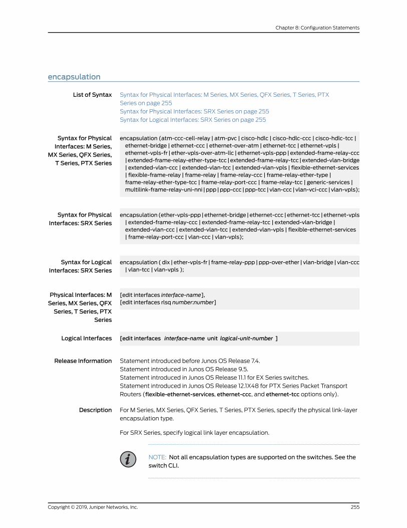
encapsulation
List of Syntax Syntax for Physical Interfaces: M Series, MX Series, QFX Series, T Series, PTX
Series on page 255
Syntax for Physical Interfaces: SRX Series on page 255
Syntax for Logical Interfaces: SRX Series on page 255
Syntax for PhysicalInterfaces: M Series,
encapsulation (atm-ccc-cell-relay | atm-pvc | cisco-hdlc | cisco-hdlc-ccc | cisco-hdlc-tcc |ethernet-bridge | ethernet-ccc | ethernet-over-atm | ethernet-tcc | ethernet-vpls |
MXSeries, QFX Series,T Series, PTX Series
ethernet-vpls-fr | ether-vpls-over-atm-llc | ethernet-vpls-ppp | extended-frame-relay-ccc|extended-frame-relay-ether-type-tcc |extended-frame-relay-tcc |extended-vlan-bridge| extended-vlan-ccc | extended-vlan-tcc | extended-vlan-vpls | flexible-ethernet-services| flexible-frame-relay | frame-relay | frame-relay-ccc | frame-relay-ether-type |frame-relay-ether-type-tcc | frame-relay-port-ccc | frame-relay-tcc | generic-services |multilink-frame-relay-uni-nni | ppp |ppp-ccc |ppp-tcc | vlan-ccc | vlan-vci-ccc | vlan-vpls);
Syntax for PhysicalInterfaces: SRX Series
encapsulation (ether-vpls-ppp |ethernet-bridge | ethernet-ccc | ethernet-tcc | ethernet-vpls| extended-frame-relay-ccc | extended-frame-relay-tcc | extended-vlan-bridge |extended-vlan-ccc | extended-vlan-tcc | extended-vlan-vpls | flexible-ethernet-services| frame-relay-port-ccc | vlan-ccc | vlan-vpls);
Syntax for LogicalInterfaces: SRX Series
encapsulation ( dix | ether-vpls-fr | frame-relay-ppp | ppp-over-ether | vlan-bridge | vlan-ccc| vlan-tcc | vlan-vpls );
Physical Interfaces: MSeries, MX Series, QFX
[edit interfaces interface-name],[edit interfaces rlsq number:number]
Series, T Series, PTXSeries
Logical Interfaces [edit interfaces interface-name unit logical-unit-number ]
Release Information Statement introduced before Junos OS Release 7.4.
Statement introduced in Junos OS Release 9.5.
Statement introduced in Junos OS Release 11.1 for EX Series switches.
Statement introduced in Junos OS Release 12.1X48 for PTX Series Packet Transport
Routers (flexible-ethernet-services, ethernet-ccc, and ethernet-tcc options only).
Description For M Series, MX Series, QFX Series, T Series, PTX Series, specify the physical link-layer
encapsulation type.
For SRX Series, specify logical link layer encapsulation.
NOTE: Not all encapsulation types are supported on the switches. See theswitch CLI.
255Copyright © 2019, Juniper Networks, Inc.
Chapter 8: Configuration Statements

Default ppp—Use serial PPP encapsulation.
Copyright © 2019, Juniper Networks, Inc.256
ATM Interfaces Feature Guide for Routing Devices
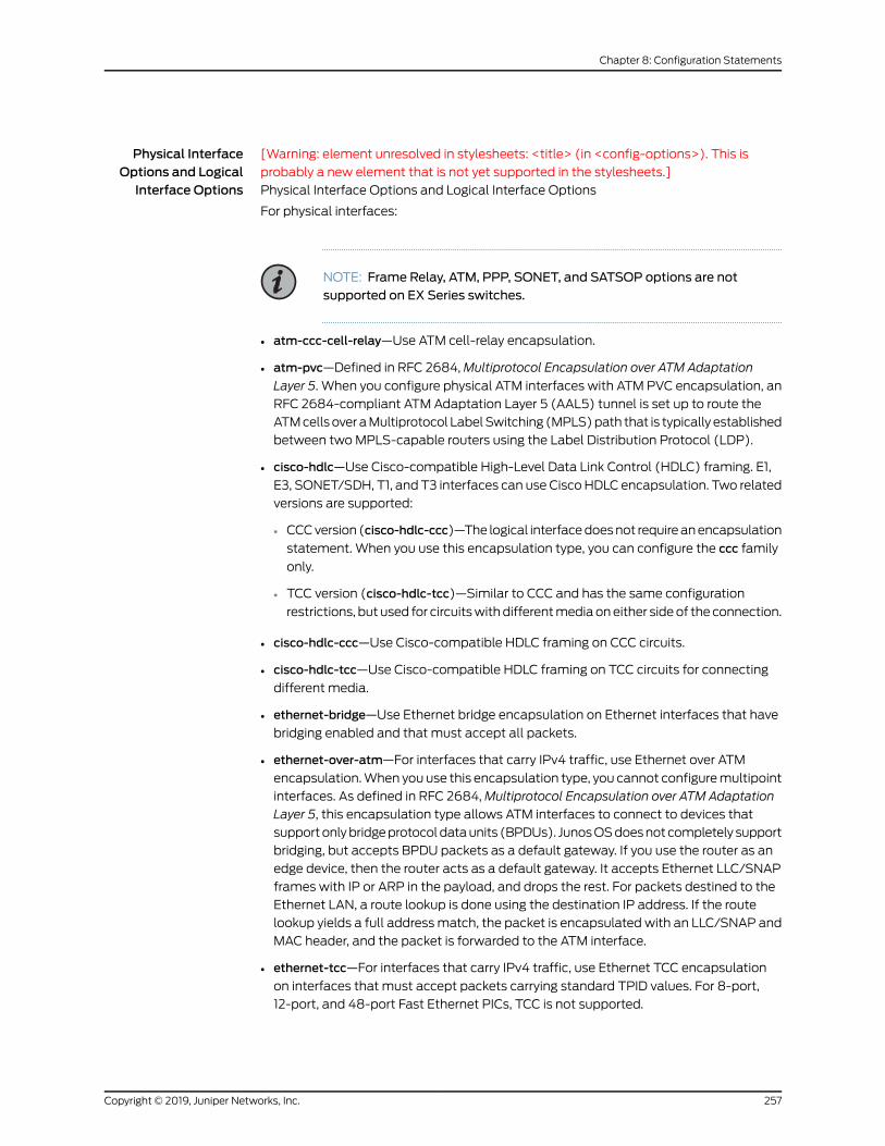
Physical InterfaceOptions and LogicalInterface Options
[Warning: element unresolved in stylesheets: <title> (in <config-options>). This is
probably a new element that is not yet supported in the stylesheets.]
Physical Interface Options and Logical Interface Options
For physical interfaces:
NOTE: Frame Relay, ATM, PPP, SONET, and SATSOP options are notsupported on EX Series switches.
• atm-ccc-cell-relay—Use ATM cell-relay encapsulation.
• atm-pvc—Defined in RFC 2684,Multiprotocol Encapsulation over ATM Adaptation
Layer 5. When you configure physical ATM interfaces with ATM PVC encapsulation, an
RFC 2684-compliant ATM Adaptation Layer 5 (AAL5) tunnel is set up to route the
ATMcellsoveraMultiprotocol LabelSwitching (MPLS)path that is typically established
between twoMPLS-capable routers using the Label Distribution Protocol (LDP).
• cisco-hdlc—Use Cisco-compatible High-Level Data Link Control (HDLC) framing. E1,
E3, SONET/SDH, T1, and T3 interfaces can use CiscoHDLC encapsulation. Two related
versions are supported:
• CCCversion (cisco-hdlc-ccc)—The logical interfacedoesnot requireanencapsulation
statement. When you use this encapsulation type, you can configure the ccc family
only.
• TCC version (cisco-hdlc-tcc)—Similar to CCC and has the same configuration
restrictions, but used for circuitswithdifferentmediaoneither sideof the connection.
• cisco-hdlc-ccc—Use Cisco-compatible HDLC framing on CCC circuits.
• cisco-hdlc-tcc—Use Cisco-compatible HDLC framing on TCC circuits for connecting
different media.
• ethernet-bridge—Use Ethernet bridge encapsulation on Ethernet interfaces that have
bridging enabled and that must accept all packets.
• ethernet-over-atm—For interfaces that carry IPv4 traffic, use Ethernet over ATM
encapsulation.When you use this encapsulation type, you cannot configuremultipoint
interfaces. As defined in RFC 2684,Multiprotocol Encapsulation over ATM Adaptation
Layer 5, this encapsulation type allows ATM interfaces to connect to devices that
supportonlybridgeprotocoldataunits (BPDUs). JunosOSdoesnotcompletely support
bridging, but accepts BPDU packets as a default gateway. If you use the router as an
edge device, then the router acts as a default gateway. It accepts Ethernet LLC/SNAP
frames with IP or ARP in the payload, and drops the rest. For packets destined to the
Ethernet LAN, a route lookup is done using the destination IP address. If the route
lookup yields a full addressmatch, the packet is encapsulated with an LLC/SNAP and
MAC header, and the packet is forwarded to the ATM interface.
• ethernet-tcc—For interfaces that carry IPv4 traffic, use Ethernet TCC encapsulation
on interfaces that must accept packets carrying standard TPID values. For 8-port,
12-port, and 48-port Fast Ethernet PICs, TCC is not supported.
257Copyright © 2019, Juniper Networks, Inc.
Chapter 8: Configuration Statements

• ethernet-vpls—Use Ethernet VPLS encapsulation on Ethernet interfaces that have
VPLS enabled and that must accept packets carrying standard TPID values. On M
Series routers, except theM320 router, the 4-port Fast Ethernet TX PIC and the 1-port,
2-port, and 4-port, 4-slot Gigabit Ethernet PICs can use the Ethernet VPLS
encapsulation type.
• ethernet-vpls-fr—Use in a VPLS setup when a CE device is connected to a PE device
over a time division multiplexing (TDM) link. This encapsulation type enables the PE
device to terminate the outer Layer 2 Frame Relay connection, use the 802.1p bits
inside the inner Ethernet header to classify the packets, look at the MAC address from
the Ethernet header, and use theMACaddress to forward the packet into a givenVPLS
instance.
• ethernet-vpls-ppp—Use in a VPLS setupwhen a CE device is connected to a PE device
over a time division multiplexing (TDM) link. This encapsulation type enables the PE
device to terminate the outer Layer 2 PPP connection, use the 802.1p bits inside the
innerEthernetheader toclassify thepackets, lookat theMACaddress fromtheEthernet
header, and use it to forward the packet into a given VPLS instance.
• ether-vpls-over-atm-llc—For ATM intelligent queuing (IQ) interfaces only, use the
Ethernet virtual private LAN service (VPLS) over ATM LLC encapsulation to bridge
Ethernet interfaces and ATM interfaces over a VPLS routing instance (as described in
RFC 2684,Multiprotocol Encapsulation over ATM Adaptation Layer 5). Packets from
the ATM interfaces are converted to standard ENET2/802.3 encapsulated Ethernet
frames with the frame check sequence (FCS) field removed.
• extended-frame-relay-ccc—Use Frame Relay encapsulation on CCC circuits. This
encapsulation type allows you to dedicate DLCIs 1 through 1022 to CCC.When you use
this encapsulation type, you can configure the ccc family only.
• extended-frame-relay-ether-type-tcc—Use extended Frame Relay ether type TCC for
Cisco-compatible Frame Relay for DLCIs 1 through 1022. This encapsulation type is
used for circuits with different media on either side of the connection.
• extended-frame-relay-tcc—Use Frame Relay encapsulation on TCC circuits to connect
different media. This encapsulation type allows you to dedicate DLCIs 1 through 1022
to TCC.
• extended-vlan-bridge—UseextendedVLANbridgeencapsulationonEthernet interfaces
thathave IEEE802.1QVLANtaggingandbridgingenabledandthatmustacceptpackets
carrying TPID 0x8100 or a user-defined TPID.
• extended-vlan-ccc—Use extended VLAN encapsulation on CCC circuits with Gigabit
Ethernet and4-port Fast Ethernet interfaces thatmustacceptpackets carrying802.1Q
values. Extended VLAN CCC encapsulation supports TPIDs 0x8100, 0x9100, and
0x9901. When you use this encapsulation type, you can configure the ccc family only.
For 8-port, 12-port, and 48-port Fast Ethernet PICs, extended VLAN CCC is not
supported. For 4-port Gigabit Ethernet PICs, extended VLAN CCC is not supported.
• extended-vlan-tcc—For interfaces that carry IPv4 traffic, use extended VLAN
encapsulation on TCC circuits with Gigabit Ethernet interfaces on which you want to
use 802.1Q tagging. For 4-port Gigabit Ethernet PICs, extended VLAN TCC is not
supported.
Copyright © 2019, Juniper Networks, Inc.258
ATM Interfaces Feature Guide for Routing Devices

• extended-vlan-vpls—Use extended VLAN VPLS encapsulation on Ethernet interfaces
that have VLAN 802.1Q tagging and VPLS enabled and that must accept packets
carrying TPIDs 0x8100, 0x9100, and 0x9901. On M Series routers, except the M320
router, the4-port Fast EthernetTXPICand the 1-port, 2-port, and4-port, 4-slotGigabit
Ethernet PICs can use the Ethernet VPLS encapsulation type.
NOTE: The built-in Gigabit Ethernet PIC on anM7i router does not supportextended VLAN VPLS encapsulation.
• flexible-ethernet-services—ForGigabit Ethernet IQ interfacesandGigabit EthernetPICs
with small form-factor pluggable transceivers (SFPs) (except the 10-port Gigabit
Ethernet PIC and the built-in Gigabit Ethernet port on the M7i router), and for Gigabit
Ethernet interfaces, use flexible Ethernet services encapsulation when you want to
configuremultipleper-unit Ethernet encapsulations. AggregatedEthernetbundles can
use this encapsulation type. This encapsulation type allows you to configure any
combination of route, TCC, CCC, Layer 2 virtual private networks (VPNs), and VPLS
encapsulations on a single physical port. If you configure flexible Ethernet services
encapsulation on the physical interface, VLAN IDs from 1 through 511 are no longer
reserved for normal VLANs.
• flexible-frame-relay—For IQ interfaces only, use flexible Frame Relay encapsulation
when you want to configure multiple per-unit Frame Relay encapsulations. This
encapsulation typeallowsyou toconfigureanycombinationofTCC,CCC,andstandard
Frame Relay encapsulations on a single physical port. Also, each logical interface can
have any DLCI value from 1 through 1022.
• frame-relay—Use Frame Relay encapsulation is defined in RFC 1490,Multiprotocol
Interconnect over Frame Relay. E1, E3, link services, SONET/SDH, T1, T3, and voice
services interfaces can use Frame Relay encapsulation.
• frame-relay-ccc—Use Frame Relay encapsulation on CCC circuits. This encapsulation
is same as standard Frame Relay for DLCIs 0 through 511. DLCIs 512 through 1022 are
dedicated to CCC. The logical interfacemust also have frame-relay-ccc encapsulation.
When you use this encapsulation type, you can configure the ccc family only.
• frame-relay-ether-type—Use Frame Relay ether type encapsulation for compatibility
with the Cisco Frame Relay. IETF frame relay encapsulation identifies the payload
format using NLPID and SNAP formats. Cisco-compatible Frame Relay encapsulation
uses the Ethernet type to identify the type of payload.
NOTE: When the encapsulation type is set to Cisco-compatible FrameRelay encapsulation, ensure that the LMI type is set to ANSI or Q933-A.
• frame-relay-ether-type-tcc—Use Frame Relay ether type TCC for Cisco-compatible
Frame Relay on TCC circuits to connect different media. This encapsulation is
Cisco-compatible Frame Relay for DLCIs 0 through 511. DLCIs 512 through 1022 are
dedicated to TCC.
259Copyright © 2019, Juniper Networks, Inc.
Chapter 8: Configuration Statements

• frame-relay-port-ccc—Use FrameRelay port CCC encapsulation to transparently carry
all the DLCIs between two customer edge (CE) routers without explicitly configuring
each DLCI on the two provider edge (PE) routers with Frame Relay transport. The
connection between the two CE routers can be either user-to-network interface (UNI)
ornetwork-to-network interface(NNI); this is completely transparent to thePE routers.
When you use this encapsulation type, you can configure the ccc family only.
• frame-relay-tcc—This encapsulation is similar to Frame Relay CCC and has the same
configuration restrictions, but used for circuits with different media on either side of
the connection.
• generic-services—Use generic services encapsulation for services with a hierarchical
scheduler.
• multilink-frame-relay-uni-nni—Use MLFR UNI NNI encapsulation. This encapsulation
is used on link services, voice services interfaces functioning as FRF.16 bundles, and
their constituent T1 or E1 interfaces, and is supported on LSQ and redundant LSQ
interfaces.
•
• ppp—Use serial PPP encapsulation. This encapsulation is defined in RFC 1661, The
Point-to-Point Protocol (PPP) for the Transmission of Multiprotocol Datagrams over
Point-to-Point Links. PPP is the default encapsulation type for physical interfaces. E1,
E3, SONET/SDH, T1, and T3 interfaces can use PPP encapsulation.
• ppp-ccc—Use serial PPP encapsulation on CCC circuits. When you use this
encapsulation type, you can configure the ccc family only.
• ppp-tcc—Use serial PPP encapsulation on TCC circuits for connecting differentmedia.
When you use this encapsulation type, you can configure the tcc family only.
• vlan-ccc—UseEthernetVLANencapsulationonCCCcircuits. VLANCCCencapsulation
supports TPID 0x8100 only. When you use this encapsulation type, you can configure
the ccc family only.
Copyright © 2019, Juniper Networks, Inc.260
ATM Interfaces Feature Guide for Routing Devices
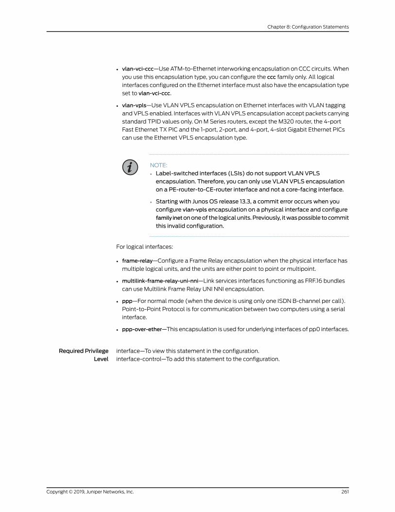
• vlan-vci-ccc—UseATM-to-Ethernet interworking encapsulation on CCC circuits.When
you use this encapsulation type, you can configure the ccc family only. All logical
interfaces configured on the Ethernet interfacemust also have the encapsulation type
set to vlan-vci-ccc.
• vlan-vpls—Use VLAN VPLS encapsulation on Ethernet interfaces with VLAN tagging
and VPLS enabled. Interfaceswith VLANVPLS encapsulation accept packets carrying
standard TPID values only. On M Series routers, except the M320 router, the 4-port
Fast Ethernet TX PIC and the 1-port, 2-port, and 4-port, 4-slot Gigabit Ethernet PICs
can use the Ethernet VPLS encapsulation type.
NOTE:
• Label-switched interfaces (LSIs) do not support VLAN VPLSencapsulation. Therefore, you can only use VLAN VPLS encapsulationon a PE-router-to-CE-router interface and not a core-facing interface.
• Starting with Junos OS release 13.3, a commit error occurs when youconfigure vlan-vpls encapsulation on a physical interface and configure
family inetononeof the logicalunits.Previously, itwaspossible tocommit
this invalid configuration.
For logical interfaces:
• frame-relay—Configure a Frame Relay encapsulation when the physical interface has
multiple logical units, and the units are either point to point or multipoint.
• multilink-frame-relay-uni-nni—Link services interfaces functioning as FRF.16 bundles
can use Multilink Frame Relay UNI NNI encapsulation.
• ppp—For normal mode (when the device is using only one ISDN B-channel per call).
Point-to-Point Protocol is for communication between two computers using a serial
interface.
• ppp-over-ether—This encapsulation is used for underlying interfaces of pp0 interfaces.
Required PrivilegeLevel
interface—To view this statement in the configuration.
interface-control—To add this statement to the configuration.
261Copyright © 2019, Juniper Networks, Inc.
Chapter 8: Configuration Statements
RelatedDocumentation
• Understanding Physical Encapsulation on an Interface
• Configuring Interface Encapsulation on Physical Interfaces
• Configuring CCC Encapsulation for Layer 2 VPNs
• Configuring Layer 2 Switching Cross-Connects Using CCC
• Configuring TCC Encapsulation for Layer 2 VPNs and Layer 2 Circuits
• Configuring ATM Interface Encapsulation on page 51
• Configuring ATM-to-Ethernet Interworking
• Configuring VLAN and Extended VLAN Encapsulation
• Configuring VLAN and Extended VLAN Encapsulation
• Configuring Encapsulation for Layer 2Wholesale VLAN Interfaces
• Configuring Interfaces for Layer 2 Circuits
• Configuring Interface Encapsulation on PTX Series Packet Transport Routers
• Configuring MPLS LSP Tunnel Cross-Connects Using CCC
• Configuring TCC
• Configuring VPLS Interface Encapsulation
• Configuring Interfaces for VPLS Routing
• Defining the Encapsulation for Switching Cross-Connects
• Configuring an MPLS-Based Layer 2 VPN (CLI Procedure)
Copyright © 2019, Juniper Networks, Inc.262
ATM Interfaces Feature Guide for Routing Devices

epd-threshold (Logical Interface)
Syntax epd-threshold cells plp1 cells;
Hierarchy Level [edit interfaces interface-name unit logical-unit-number],[edit interfaces interface-name unit logical-unit-number address address family familymultipoint-destination address],
[edit logical-systems logical-system-name interfaces interface-nameunit logical-unit-number],[edit logical-systems logical-system-name interfaces interface-nameunit logical-unit-numberaddress address family familymultipoint-destination address]
Release Information Statement introduced before Junos OS Release 7.4.
Statement introduced in Junos OS Release 11.1 for the QFX Series.
Description For ATM2 IQ interfaces only, define the early packet discard (EPD) threshold on a VC.
The EPD threshold is a limit on the number of transmit packets that can be queued.
Packets that exceed the limit are discarded. For interfaces configured in trunkmode, you
can also configure dual EPD thresholds depending on the packet loss priorities (PLPs).
Default Approximately 1 percent of the available cell buffers. If shaping is enabled, the default
EPD threshold is proportional to the shaping rate according to the following formula:
default epd-threshold = number of buffers * shaping rate / line rate
TheminimumEPDthresholdvalue is48cells. If thedefault EPDthreshold formula results
in an EPD threshold of less than 48 cells, the result will be ignored, and theminimum
value of 48 cells will be used.
Options cells—Maximum number of cells.
Range: For 1-port and 2-port OC12 interfaces, 48 through 425,984 cells
Required PrivilegeLevel
interface—To view this statement in the configuration.
interface-control—To add this statement to the configuration.
RelatedDocumentation
• Configuring the ATM2 IQ EPD Threshold on page 131
• Configuring Two EPD Thresholds per Queue on page 133
263Copyright © 2019, Juniper Networks, Inc.
Chapter 8: Configuration Statements
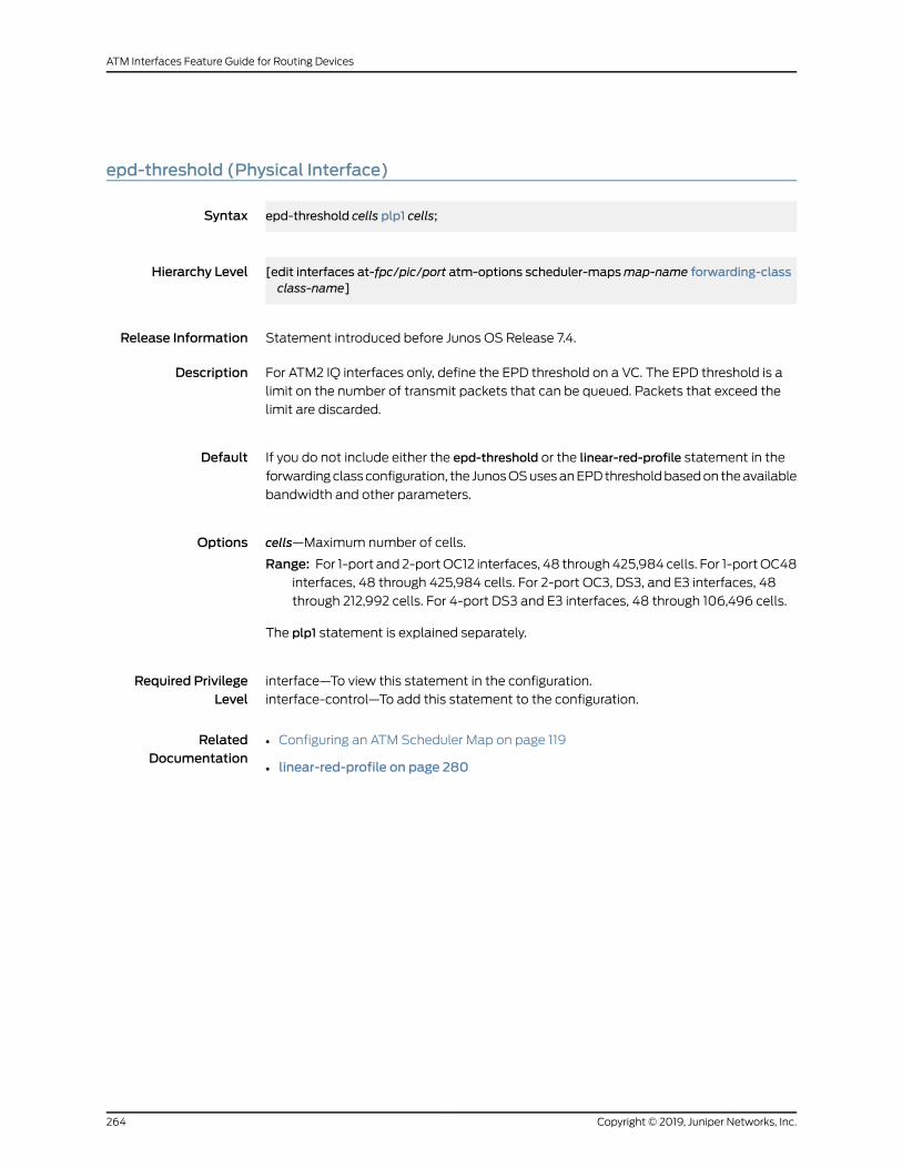
epd-threshold (Physical Interface)
Syntax epd-threshold cells plp1 cells;
Hierarchy Level [edit interfaces at-fpc/pic/port atm-options scheduler-mapsmap-name forwarding-classclass-name]
Release Information Statement introduced before Junos OS Release 7.4.
Description For ATM2 IQ interfaces only, define the EPD threshold on a VC. The EPD threshold is a
limit on the number of transmit packets that can be queued. Packets that exceed the
limit are discarded.
Default If you do not include either the epd-threshold or the linear-red-profile statement in the
forwardingclassconfiguration, the JunosOSusesanEPDthresholdbasedon theavailable
bandwidth and other parameters.
Options cells—Maximum number of cells.
Range: For 1-port and 2-portOC12 interfaces, 48 through425,984 cells. For 1-portOC48interfaces, 48 through 425,984 cells. For 2-port OC3, DS3, and E3 interfaces, 48
through 212,992 cells. For 4-port DS3 and E3 interfaces, 48 through 106,496 cells.
The plp1 statement is explained separately.
Required PrivilegeLevel
interface—To view this statement in the configuration.
interface-control—To add this statement to the configuration.
RelatedDocumentation
• Configuring an ATM Scheduler Map on page 119
• linear-red-profile on page 280
Copyright © 2019, Juniper Networks, Inc.264
ATM Interfaces Feature Guide for Routing Devices

family
Syntax family family {accounting {destination-class-usage;source-class-usage {(input | output | input output);
}}access-concentrator name;address address {... the address subhierarchy appears after the main [edit interfaces interface-name unitlogical-unit-number family family-name] hierarchy ...
}bundle interface-name;core-facing;demux-destination {destination-prefix;
}demux-source {source-prefix;
}direct-connect;duplicate-protection;dynamic-profile profile-name;filter {group filter-group-number;input filter-name;input-list [ filter-names ];output filter-name;output-list [ filter-names ];
}interface-mode (access | trunk);ipsec-sa sa-name;keep-address-and-control;mac-validate (loose | strict);max-sessions number;max-sessions-vsa-ignore;mtu bytes;multicast-only;nd6-stale-time seconds;negotiate-address;no-neighbor-learn;no-redirects;policer {arp policer-template-name;input policer-template-name;output policer-template-name;
}primary;protocols [inet isompls];proxy inet-address address;receive-options-packets;
265Copyright © 2019, Juniper Networks, Inc.
Chapter 8: Configuration Statements

receive-ttl-exceeded;remote (inet-address address | mac-address address);rpf-check {fail-filter filter-namemode loose;
}sampling {input;output;
}service {input {post-service-filter filter-name;service-set service-set-name <service-filter filter-name>;
}output {service-set service-set-name <service-filter filter-name>;
}}service-name-table table-name;short-cycle-protection <lockout-time-minminimum-seconds lockout-time-maxmaximum-seconds> <filter [aci]>;
(translate-discard-eligible | no-translate-discard-eligible);(translate-fecn-and-becn | no-translate-fecn-and-becn);translate-plp-control-word-de;unnumbered-address interface-namedestinationaddressdestination-profileprofile-name;vlan-id number;vlan-id-list [number number-number];address address {arp ip-address (mac | multicast-mac)mac-address <publish>;broadcast address;destination address;destination-profile name;eui-64;master-only;multipoint-destination address dlci dlci-identifier;multipoint-destination address {epd-threshold cells;inverse-arp;oam-liveness {up-count cells;down-count cells;
}oam-period (disable | seconds);shaping {(cbr rate | rtvbr burst length peak rate sustained rate | vbr burst length peak ratesustained rate);
queue-length number;}vci vpi-identifier.vci-identifier;
}preferred;primary;vrrp-groupgroup-id {(accept-data | no-accept-data);
Copyright © 2019, Juniper Networks, Inc.266
ATM Interfaces Feature Guide for Routing Devices

advertise-interval seconds;authentication-key key;authentication-type authentication;fast-intervalmilliseconds;(preempt | no-preempt) {hold-time seconds;
}priority number;track {interface interface-name {bandwidth-threshold bits-per-second priority-cost priority;priority-cost priority;
}priority-hold-time seconds;route prefix routing-instance instance-name priority-cost priority;}
}virtual-address [ addresses ];}
virtual-link-local-address ipv6-address;}
}
Hierarchy Level [edit interfaces interface-name unit logical-unit-number],[edit logical-systems logical-system-name interfaces interface-nameunit logical-unit-number]
Release Information Statement introduced before Junos OS Release 7.4.
Optionmax-sessions-vsa-ignore introduced in Junos OS Release 11.4.
Description Configure protocol family information for the logical interface.
NOTE: Not all subordinate statements are available to every protocol family.
267Copyright © 2019, Juniper Networks, Inc.
Chapter 8: Configuration Statements
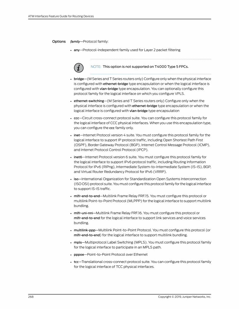
Options family—Protocol family:
• any—Protocol-independent family used for Layer 2 packet filtering
NOTE: This option is not supported on T4000 Type 5 FPCs.
• bridge—(MSeries andTSeries routers only)Configure onlywhen thephysical interface
is configured with ethernet-bridge type encapsulation or when the logical interface is
configured with vlan-bridge type encapsulation. You can optionally configure this
protocol family for the logical interface on which you configure VPLS.
• ethernet-switching—(M Series and T Series routers only) Configure only when the
physical interface is configured with ethernet-bridge type encapsulation or when the
logical interface is configured with vlan-bridge type encapsulation
• ccc—Circuit cross-connect protocol suite. You can configure this protocol family for
the logical interface of CCC physical interfaces.When you use this encapsulation type,
you can configure the ccc family only.
• inet—Internet Protocol version 4 suite. Youmust configure this protocol family for the
logical interface to support IP protocol traffic, including Open Shortest Path First
(OSPF), Border Gateway Protocol (BGP), Internet Control Message Protocol (ICMP),
and Internet Protocol Control Protocol (IPCP).
• inet6—Internet Protocol version 6 suite. Youmust configure this protocol family for
the logical interface to support IPv6 protocol traffic, including Routing Information
Protocol for IPv6 (RIPng), Intermediate System-to-Intermediate System (IS-IS), BGP,
and Virtual Router Redundancy Protocol for IPv6 (VRRP).
• iso—International Organization for Standardization Open Systems Interconnection
(ISOOSI)protocol suite. Youmust configure this protocol family for the logical interface
to support IS-IS traffic.
• mlfr-end-to-end—Multilink Frame Relay FRF.15. Youmust configure this protocol or
multilink Point-to-Point Protocol (MLPPP) for the logical interface to supportmultilink
bundling.
• mlfr-uni-nni—Multilink Frame Relay FRF.16. Youmust configure this protocol or
mlfr-end-to-end for the logical interface to support link services and voice services
bundling.
• multilink-ppp—Multilink Point-to-Point Protocol. Youmust configure this protocol (or
mlfr-end-to-end) for the logical interface to support multilink bundling.
• mpls—Multiprotocol Label Switching (MPLS). Youmust configure this protocol family
for the logical interface to participate in an MPLS path.
• pppoe—Point-to-Point Protocol over Ethernet
• tcc—Translational cross-connect protocol suite. You can configure this protocol family
for the logical interface of TCC physical interfaces.
Copyright © 2019, Juniper Networks, Inc.268
ATM Interfaces Feature Guide for Routing Devices

• tnp—Trivial Network Protocol. This protocol is used to communicate between the
Routing Engine and the router’s packet forwarding components. The Junos OS
automatically configures this protocol family on the router’s internal interfaces only,
as discussed in Understanding Internal Ethernet Interfaces.
• vpls—(MSeriesandTSeries routersonly)Virtual privateLANservice. Youcanoptionally
configure this protocol family for the logical interface on which you configure VPLS.
VPLSprovidesanEthernet-basedpoint-to-multipointLayer2VPNtoconnectcustomer
edge(CE) routersacrossanMPLSbackbone.WhenyouconfigureaVPLSencapsulation
type, the family vpls statement is assumed by default.
MX Series routers support dynamic profiles for VPLS pseudowires, VLAN identifier
translation, and automatic bridge domain configuration.
For more information about VPLS, see the Junos OS VPNs Library for Routing Devices.
The remaining statements are explained separately. See CLI Explorer.
Required PrivilegeLevel
interface—To view this statement in the configuration.
interface-control—To add this statement to the configuration.
RelatedDocumentation
• Configuring the Protocol Family
269Copyright © 2019, Juniper Networks, Inc.
Chapter 8: Configuration Statements

fast-aps-switch
Syntax fast-aps-switch;
Hierarchy Level [edit interfaces interface-name sonet-options aps]
Release Information Statement introduced in Junos OS Release 12.1.
Description (M320 routers with Channelized OC3/STM1 Circuit Emulation PIC with SFP only, EX
Series switches, and MX series routers with Channelized OC3/STM1 Circuit Emulation
PICwithSFPonly using container interfaces)Reduce theAutomaticProtectionSwitching
(APS) switchover time in Layer 2 circuits.
NOTE:
• The fast APS switching feature is supported only within a single chassison aMX series router using a container interface.
• Configuring this statement reduces the APS switchover time only whentheLayer2circuit encapsulation type for the interface receiving traffic froma Layer 2 circuit neighbor is SAToP.
• When the fast-aps-switch statement is configured in revertive APSmode,
youmustconfigureanappropriatevalue for revert timetoachieve reductionin APS switchover time.
• To prevent the logical interfaces in the data path from being shut down,configure appropriate hold-time values on all the interfaces in the datapath that support TDM.
• The fast-aps-switchstatementcannotbeconfiguredwhentheAPSannex-b
option is configured.
• The interfaces that have the fast-aps-switch statement configured cannot
be used in virtual private LAN service (VPLS) environments.
Required PrivilegeLevel
interface—To view this statement in the configuration.
interface-control—To add this statement to the configuration.
RelatedDocumentation
• Reducing APS Switchover Time in Layer 2 Circuits
Copyright © 2019, Juniper Networks, Inc.270
ATM Interfaces Feature Guide for Routing Devices

force
Syntax force (protect | working);
Hierarchy Level [edit interfaces interface-name sonet-options aps]
Release Information Statement introduced before Junos OS Release 7.4.
Description Perform a forced switch between the protect and working circuits. This statement is
honored only if there are no higher-priority reasons to switch. It can be overridden by a
signal failure on the protect circuit, thus causing a switch to the working circuit.
Options protect—Request the circuit to become the protect circuit.
working—Request the circuit to become the working circuit.
Required PrivilegeLevel
interface—To view this statement in the configuration.
interface-control—To add this statement to the configuration.
RelatedDocumentation
• Configuring Switching Between theWorking and Protect Circuits
• request on page 307
271Copyright © 2019, Juniper Networks, Inc.
Chapter 8: Configuration Statements

forwarding-class (ATM2 IQ Scheduler Maps)
Syntax forwarding-class class-name {epd-threshold cells plp1 cells;linear-red-profile profile-name;priority (high | low);transmit-weight (cells number | percent number);
}
Hierarchy Level [edit interfaces at-fpc/pic/port atm-options scheduler-mapsmap-name]
Release Information Statement introduced before Junos OS Release 7.4.
Description For ATM2 IQ interfaces only, define forwarding class name and option values.
Options class-name—Name of forwarding class.
The remaining statements are explained separately. See CLI Explorer.
Required PrivilegeLevel
interface—To view this statement in the configuration.
interface-control—To add this statement to the configuration.
RelatedDocumentation
• ATM2 IQ VC Tunnel CoS Components Overview on page 117
• Applying Scheduler Maps to ATM Interfaces
Copyright © 2019, Juniper Networks, Inc.272
ATM Interfaces Feature Guide for Routing Devices
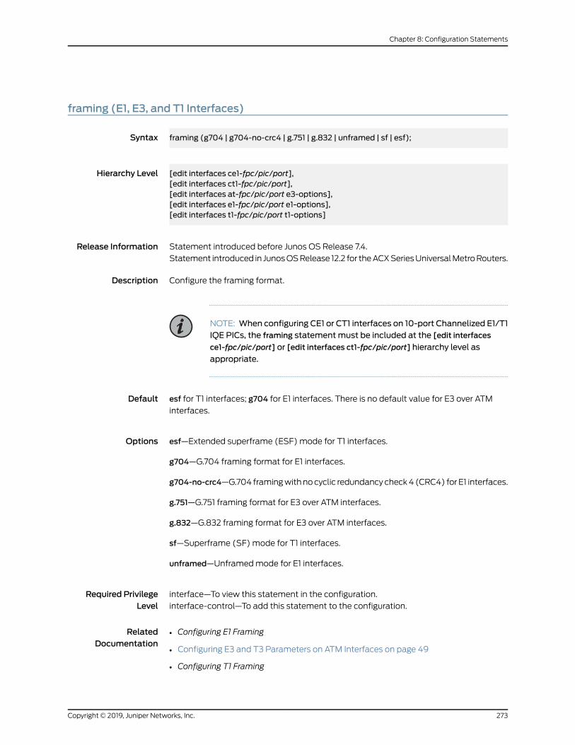
framing (E1, E3, and T1 Interfaces)
Syntax framing (g704 | g704-no-crc4 | g.751 | g.832 | unframed | sf | esf);
Hierarchy Level [edit interfaces ce1-fpc/pic/port],[edit interfaces ct1-fpc/pic/port],[edit interfaces at-fpc/pic/port e3-options],[edit interfaces e1-fpc/pic/port e1-options],[edit interfaces t1-fpc/pic/port t1-options]
Release Information Statement introduced before Junos OS Release 7.4.
Statement introduced in JunosOSRelease 12.2 for theACXSeriesUniversalMetroRouters.
Description Configure the framing format.
NOTE: When configuring CE1 or CT1 interfaces on 10-port Channelized E1/T1IQE PICs, the framing statementmust be included at the [edit interfaces
ce1-fpc/pic/port] or [edit interfaces ct1-fpc/pic/port] hierarchy level as
appropriate.
Default esf for T1 interfaces; g704 for E1 interfaces. There is no default value for E3 over ATM
interfaces.
Options esf—Extended superframe (ESF) mode for T1 interfaces.
g704—G.704 framing format for E1 interfaces.
g704-no-crc4—G.704 framingwithnocyclic redundancycheck4 (CRC4) for E1 interfaces.
g.751—G.751 framing format for E3 over ATM interfaces.
g.832—G.832 framing format for E3 over ATM interfaces.
sf—Superframe (SF) mode for T1 interfaces.
unframed—Unframedmode for E1 interfaces.
Required PrivilegeLevel
interface—To view this statement in the configuration.
interface-control—To add this statement to the configuration.
RelatedDocumentation
• Configuring E1 Framing
• Configuring E3 and T3 Parameters on ATM Interfaces on page 49
• Configuring T1 Framing
273Copyright © 2019, Juniper Networks, Inc.
Chapter 8: Configuration Statements

high-plp-max-threshold
Syntax high-plp-max-threshold percent;
Hierarchy Level [edit interfaces at-fpc/pic/port atm-options linear-red-profiles profile-name]
Release Information Statement introduced before Junos OS Release 7.4.
Description For ATM2 IQ interfaces only, define the drop profile fill-level for the high PLP CoS VC.
When the fill level exceeds the defined percentage, all packets are dropped.
Options percent—Fill-level percentagewhen linear random early discard (RED) is applied to cells
with PLP.
Required PrivilegeLevel
interface—To view this statement in the configuration.
interface-control—To add this statement to the configuration.
RelatedDocumentation
• ATM2 IQ VC Tunnel CoS Components Overview on page 117
• low-plp-max-threshold on page 285
• low-plp-threshold on page 286
• queue-depth on page 304
Copyright © 2019, Juniper Networks, Inc.274
ATM Interfaces Feature Guide for Routing Devices
high-plp-threshold
Syntax high-plp-threshold percent;
Hierarchy Level [edit interfaces at-fpc/pic/port atm-options linear-red-profiles profile-name]
Release Information Statement introduced before Junos OS Release 7.4.
Description For ATM2 IQ interfaces only, define CoS VC drop profile fill-level percentage when linear
RED is applied to cells with high PLP.When the fill level exceeds the defined percentage,
packets with high PLP are randomly dropped by RED. This statement is mandatory.
Options percent—Fill-level percentage when linear RED is applied to cells with PLP.
Required PrivilegeLevel
interface—To view this statement in the configuration.
interface-control—To add this statement to the configuration.
RelatedDocumentation
• ATM2 IQ VC Tunnel CoS Components Overview on page 117
• high-plp-max-threshold on page 274
• low-plp-max-threshold on page 285
• low-plp-threshold on page 286
• queue-depth on page 304
275Copyright © 2019, Juniper Networks, Inc.
Chapter 8: Configuration Statements

hold-time (APS)
Syntax hold-timemilliseconds;
Hierarchy Level [edit interfaces interface-name sonet-options aps]
Release Information Statement introduced before Junos OS Release 7.4.
Description Hold-time value to use to determine whether a neighbor APS router is operational.
Options milliseconds—Hold-time value.
Range: 1 through 65,534milliseconds
Default: 3000milliseconds (3 times the advertisement interval)
Required PrivilegeLevel
interface—To view this statement in the configuration.
interface-control—To add this statement to the configuration.
RelatedDocumentation
• Configuring APS Timers
• advertise-interval on page 237
Copyright © 2019, Juniper Networks, Inc.276
ATM Interfaces Feature Guide for Routing Devices
hold-time (SONET/SDHDefect Triggers)
Syntax hold-time upmilliseconds downmilliseconds;
Hierarchy Level [edit interfaces interface-name sonet-options trigger defect]
Release Information Statement introduced before Junos OS Release 7.4.
Description For ATM over SONET/SDH and SONET/SDH interfaces only, apply up and down hold
times to SONET/SDH defect triggers. When you apply a down hold time to a defect, the
defect must remain present for at least the hold-time period before the interface is
marked down. When you apply an up hold time to a defect, the defect must remain
absent for at least the hold-time period before the interface is marked up, assuming no
other defect is outstanding.
NOTE:
• When up or down hold times are applied to SONET defect triggers of a10-Gigabit EthernetWAN-PHY interface, only the defects generated in theWAN Interface Sublayer (WIS) are damped. Therefore, if the hold timesareapplied toSONETdefect triggersonly, a 10-Gigabit EthernetWAN-PHYinterfacemight bemarked up or down because of the faults that aregenerated in other layers, such as the Physical Coding Sublayer (PCS) orPhysical Medium Attachment Sublayer (PMA), 10 Gigabit MediaIndependent Interface (XGMII) Extender Sublayer (XGXS), andMediaAccess Control (MAC). To damp the interface up or down events of a10-Gigabit EthernetWAN-PHY interface, you need to apply up or downhold-times for the interfaceat the [edit interfaces interface-name]hierarchy
level.
• OnMSeries and T Series platforms with Channelized SONET IQ PICs andChannelized SONET IQE PICs, the SONET defect alarm trigger hold-time
statement is not supported.
Default If you do not include this statement, when a defect is detected the interface is marked
down immediately, and when the defect becomes absent the interface is marked up
immediately.
Options downmilliseconds—Hold time to wait before the interface is marked down.
Range: 1 through 65,534milliseconds
Default: No hold time
upmilliseconds—Hold time to wait before the interface is marked up.
277Copyright © 2019, Juniper Networks, Inc.
Chapter 8: Configuration Statements
Range: 1 through 65,534milliseconds
Default: No hold time
Required PrivilegeLevel
interface—To view this statement in the configuration.
interface-control—To add this statement to the configuration.
RelatedDocumentation
• Configuring SONET/SDH Defect Triggers
• hold-time (Physical Interface)
ilmi
Syntax ilmi;
Hierarchy Level [edit interfaces at-fpc/pic/port atm-options]
Release Information Statement introduced before Junos OS Release 7.4.
Description Enable the router to communicate with directly attached ATM switches and routers. The
router uses the VC 0.16 to communicate with the ATM switch or router. Once configured,
you can display the IP address and port number of an ATM switch or router using the
show interfaces interface-name switch-id command.
Required PrivilegeLevel
interface—To view this statement in the configuration.
interface-control—To add this statement to the configuration.
RelatedDocumentation
• Configuring Communication with Directly Attached ATM Switches and Routers on
page 47
• show ilmi on page 344
• show ilmi statistics on page 346
Copyright © 2019, Juniper Networks, Inc.278
ATM Interfaces Feature Guide for Routing Devices

inverse-arp
Syntax inverse-arp;
Hierarchy Level [edit interfaces interface-name unit logical-unit-number],[edit interfaces interface-name unit logical-unit-number family inet address addressmultipoint-destination destination],
[edit logical-systems logical-system-name interfaces interface-nameunit logical-unit-number],[edit logical-systems logical-system-name interfaces interface-nameunit logical-unit-numberfamily inet address addressmultipoint-destination destination]
Release Information Statement introduced before Junos OS Release 7.4.
Statement introduced in Junos OS Release 11.1 for the QFX Series.
Description For ATM encapsulation, enable responses to receive inverse ATM ARP requests. For
Frame Relay encapsulation, enable responses to receive inverse Frame Relay ARP
requests.
Default Inverse ARP is disabled on all ATM and Frame Relay interfaces.
Required PrivilegeLevel
interface—To view this statement in the configuration.
interface-control—To add this statement to the configuration.
RelatedDocumentation
• Configuring Inverse ATM1 or ATM2 ARP on page 117
• Configuring Inverse Frame Relay ARP
279Copyright © 2019, Juniper Networks, Inc.
Chapter 8: Configuration Statements

linear-red-profile
Syntax linear-red-profile profile-name;
Hierarchy Level [edit interfaces at-fpc/pic/port atm-options scheduler-mapsmap-name forwarding-classclass-name]
Release Information Statement introduced before Junos OS Release 7.4.
Description For ATM2 IQ interfaces only, assign a linear RED profile to a specified forwarding class.
To define the linear RED profiles, include the linear-red-profiles statement at the [editinterfaces at-fpc/pic/port atm-options] hierarchy level.
Default If you do not include either the epd-threshold or the linear-red-profile statement in the
forwardingclassconfiguration, the JunosOSusesanEPDthresholdbasedon theavailable
bandwidth and other parameters.
Options profile-name—Name of the linear RED profile.
Required PrivilegeLevel
interface—To view this statement in the configuration.
interface-control—To add this statement to the configuration.
RelatedDocumentation
• Configuring an ATM Scheduler Map on page 119
• linear-red-profiles on page 281
• Applying Scheduler Maps to ATM Interfaces
• epd-threshold
Copyright © 2019, Juniper Networks, Inc.280
ATM Interfaces Feature Guide for Routing Devices

linear-red-profiles
Syntax linear-red-profiles profile-name {high-plp-threshold percent;low-plp-threshold percent;queue-depth cells;
}
Hierarchy Level [edit interfaces at-fpc/pic/port atm-options]
Release Information Statement introduced before Junos OS Release 7.4.
Description For ATM2 IQ interfaces only, define CoS virtual circuit drop profiles for RED. When a
packet arrives, RED checks the queue fill level. If the fill level corresponds to a nonzero
drop probability, the RED algorithm determines whether to drop the arriving packet.
Options profile-name—Name of the drop profile.
The remaining statements are explained separately. See CLI Explorer.
Required PrivilegeLevel
interface—To view this statement in the configuration.
interface-control—To add this statement to the configuration.
RelatedDocumentation
• ATM2 IQ VC Tunnel CoS Components Overview on page 117
• Configuring Linear RED Profiles on ATM Interfaces
281Copyright © 2019, Juniper Networks, Inc.
Chapter 8: Configuration Statements

lockout
Syntax lockout;
Hierarchy Level [edit interfaces interface-name sonet-options aps]
Release Information Statement introduced before Junos OS Release 7.4.
Description Configure a lockout of protection, forcing the use of the working circuit and locking out
the protect circuit regardless of anything else.
Required PrivilegeLevel
interface—To view this statement in the configuration.
interface-control—To add this statement to the configuration.
RelatedDocumentation
• Configuring Switching Between theWorking and Protect Circuits
Copyright © 2019, Juniper Networks, Inc.282
ATM Interfaces Feature Guide for Routing Devices

loopback (ADSL, DS0, E1/E3, SONET/SDH, SHDSL, and T1/T3)
Syntax loopback (local | payload | remote);
Hierarchy Level [edit interfaces ce1-fpc/pic/port],[edit interfaces ct1-fpc/pic/port],[edit interfaces t1-fpc/pic/port],[edit interfaces interface-name ds0-options],[edit interfaces interface-name dsl-options],[edit interfaces interface-name e1-options],[edit interfaces interface-name e3-options],[edit interfaces interface-name shdsl-options},[edit interfaces interface-name sonet-options],[edit interfaces interface-name t1-options],[edit interfaces interface-name t3-options]
Release Information Statement introduced before Junos OS Release 7.4.
Statement introduced in JunosOSRelease 12.2 for theACXSeriesUniversalMetroRouters.
Description Configurea loopbackconnection.To turnoff the loopbackcapability, remove the loopback
statement from the configuration.
NOTE: When configuring CE1 or CT1 interfaces on 10-port Channelized E1/T1IQE PICs, the loopback statementmust be included with the local or remote
option at the [edit interfaces ce1-fpc/pic/port] or [edit interfaces
ct1-fpc/pic/port] hierarchy level as appropriate.
When configuring T1 interfaces on 10-port Channelized E1/T1 IQE PICs, theloopback statementmust be included with the payload option at the [edit
interfaces t1-fpc/pic/port] hierarchy level.
NOTE: When configuring CE1 or CT1 interfaces on the 16-port ChannelizedE1/T1MIC(MIC-3D-16CHE1-T1-CE), youmust include the loopbackstatement
at the [edit interfaces ce1-fpc/pic/port] hierarchy level, or [edit interfaces
ct1-fpc/pic/port]
To configure loopback on channelized IQ and IQE PICs, SONET/SDH level, use the
sonet-options loopback statement local and remote options at the controller interface
(coc48, cstm16, coc12, cstm4, coc3, cstm1). It is ignored for path-level interfaces
so-fpc/pic/port or so-fpc/pic/port:channel.
283Copyright © 2019, Juniper Networks, Inc.
Chapter 8: Configuration Statements

Options local—Looppackets, includingbothdataand timing information, backon the local router’s
PIC. NxDS0 IQ interfaces do not support local loopback.
payload—For channelized T3, T1, and NxDS0 IQ interfaces only, loop back data only
(without clocking information) on the remote router’s PIC. With payload loopback,
overhead is recalculated. Neither ATM-over-asymmetrical digital subscriber line
(ADSL) interfaces nor ATM-over-SHDSL interfaces support payload loopback.
remote—Loop packets, including both data and timing information, back on the remote
router’s interface card. NxDS0 IQ interfaces do not support remote loopback.
Required PrivilegeLevel
interface—To view this statement in the configuration.
interface-control—To add this statement to the configuration.
RelatedDocumentation
• Configuring E3 and T3 Parameters on ATM Interfaces on page 49
• Configuring E1 Loopback Capability
• Configuring E3 Loopback Capability
• ConfiguringSONET/SDHLoopbackCapability to Identify aProblemas Internal or External
• Configuring SHDSL Operating Mode on an ATM Physical Interface on page 157
• Configuring T1 Loopback Capability
• Configuring T3 Loopback Capability
• feac-loop-respond
Copyright © 2019, Juniper Networks, Inc.284
ATM Interfaces Feature Guide for Routing Devices

low-plp-max-threshold
Syntax low-plp-max-threshold percent;
Hierarchy Level [edit interfaces at-fpc/pic/port atm-options linear-red-profiles profile-name]
Release Information Statement introduced before Junos OS Release 7.4.
Description For ATM2 IQ interfaces only, define the drop profile fill-level for the low PLP CoS VC.
When the fill level exceeds the defined percentage, all packets are dropped.
Options percent—Fill-level percentage when linear RED is applied to cells with PLP.
Required PrivilegeLevel
interface—To view this statement in the configuration.
interface-control—To add this statement to the configuration.
RelatedDocumentation
• ATM2 IQ VC Tunnel CoS Components Overview on page 117
• high-plp-max-threshold on page 274
• low-plp-threshold on page 286
• Configuring Linear RED Profiles on ATM Interfaces
• high-plp-max-threshold
• queue-depth on page 304
285Copyright © 2019, Juniper Networks, Inc.
Chapter 8: Configuration Statements

low-plp-threshold
Syntax low-plp-threshold percent;
Hierarchy Level [edit interfaces at-fpc/pic/port atm-options linear-red-profiles profile-name]
Release Information Statement introduced before Junos OS Release 7.4.
Description For ATM2 IQ interfaces only, define the CoS VC drop profile fill-level percentage when
linear RED is applied to cells with low PLP. When the fill level exceeds the defined
percentage, packets with low PLP are randomly dropped by RED. This statement is
mandatory.
Options percent—Fill-level percentage when linear RED is applied to cells with low PLP.
Required PrivilegeLevel
interface—To view this statement in the configuration.
interface-control—To add this statement to the configuration.
RelatedDocumentation
• ATM2 IQ VC Tunnel CoS Components Overview on page 117
• high-plp-max-threshold on page 274
• high-plp-threshold on page 275
• Configuring Linear RED Profiles on ATM Interfaces
• high-plp-max-threshold
• high-plp-threshold
• low-plp-max-threshold on page 285
• queue-depth on page 304
Copyright © 2019, Juniper Networks, Inc.286
ATM Interfaces Feature Guide for Routing Devices
maximum-vcs
Syntax maximum-vcsmaximum-vcs;
Hierarchy Level [edit interfaces at-fpc/pic/port atm-options vpi vpi-identifier]
Release Information Statement introduced before Junos OS Release 7.4.
Description For ATM1 interfaces, configure the maximum number of virtual circuits (VCs) allowed
on a virtual path (VP).When configuring ATM1 interfaces on the router, youmust include
this statement.
For a configured virtual path identifier (VPI), valid virtual channel identifier (VCI) numbers
are from 0 through (maximum-vcs value – 1). VCI numbers 0 through 31 are reserved by
the ATM Forum. It is recommended that you use a VCI number higher than 31 when
connecting to an ATM switch.
Options maximum-vcs—Maximum number of VCs on the VP.
Range: 1 through 4090
Required PrivilegeLevel
interface—To view this statement in the configuration.
interface-control—To add this statement to the configuration.
RelatedDocumentation
• Configuring the MaximumNumber of ATM1 VCs on a VP on page 46
• multipoint-destination on page 290
• promiscuous-mode on page 302
• vci on page 330
287Copyright © 2019, Juniper Networks, Inc.
Chapter 8: Configuration Statements

mpls (Interfaces)
Syntax mpls {pop-all-labels {required-depth number;
}}
Hierarchy Level [edit interfaces interface-name atm-options],[edit interfaces interface-name sonet-options],[edit interfaces interface-name fastether-options],[edit interfaces interface-name gigether-options]
Release Information Statement introduced before Junos OS Release 7.4.
Description For passive monitoring on ATM and SONET/SDH interfaces and 10-Gigabit Ethernet
interfaces inWAN PHYmode, process incoming IP packets that have MPLS labels.
The remaining statements are explained separately. See CLI Explorer.
Required PrivilegeLevel
interface—To view this statement in the configuration.
interface-control—To add this statement to the configuration.
RelatedDocumentation
• Removing MPLS Labels from Incoming Packets on page 140
• Enabling Packet FlowMonitoring on SONET/SDH Interfaces
• Junos OS Services Interfaces Library for Routing Devices
Copyright © 2019, Juniper Networks, Inc.288
ATM Interfaces Feature Guide for Routing Devices

multicast-vci
Syntax multicast-vci vpi-identifier.vci-identifier;
Hierarchy Level [edit interfaces interface-name unit logical-unit-number],[edit logical-systems logical-system-name interfaces interface-nameunit logical-unit-number]
Release Information Statement introduced before Junos OS Release 7.4.
Description For ATM encapsulation only, and for point-to-multipoint ATM logical interfaces only,
enable the support of multicast on the interface. You can configure multicast support
on the interface if the ATM switch performsmulticast replication.
Options vci-identifier—ATM virtual circuit identifier.
Range: 0 through 16,384
vpi-identifier—ATM virtual path identifier.
Range: 0 through 255
Default: 0
Required PrivilegeLevel
interface—To view this statement in the configuration.
interface-control—To add this statement to the configuration.
RelatedDocumentation
• Configuring a Multicast-Capable ATM1 or ATM2 IQ Connection on page 86
• multipoint-destination on page 290
• vci on page 330
289Copyright © 2019, Juniper Networks, Inc.
Chapter 8: Configuration Statements

multipoint-destination
Syntax multipoint-destination address dlci dlci-identifier;multipoint-destination address {epd-threshold cells;inverse-arp;oam-liveness {down-count cells;up-count cells;
}oam-period (disable | seconds);shaping {(cbr rate | rtvbr peak rate sustained rate burst length | vbr peak rate sustained rate burstlength);
queue-length number;}vci vpi-identifier.vci-identifier;
}
Hierarchy Level [edit interfaces interface-name unit logical-unit-number family family address address],[edit logical-systems logical-system-name interfaces interface-nameunit logical-unit-numberfamily family address address]
Release Information Statement introduced before Junos OS Release 7.4.
Description For point-to-multipoint Frame Relay or ATM interfaces only, enable the support of
multicast on the interface. You can configure multicast support on the interface if the
Frame Relay or ATM switch performsmulticast replication.
Options address—Address of the remote side of the point-to-multipoint connection.
dlci-identifier—For Frame Relay interfaces, the data-link connection identifier.
Range: 0 through 0xFFFFFF (24 bits)
vci-identifier—For ATM interfaces, the virtual circuit identifier.
Range: 0 through 16,384
vpi-identifier—For ATM interfaces, the virtual path identifier.
Range: 0 through 255
Default: 0
The remaining statements are explained separately. See CLI Explorer.
Required PrivilegeLevel
interface—To view this statement in the configuration.
interface-control—To add this statement to the configuration.
Copyright © 2019, Juniper Networks, Inc.290
ATM Interfaces Feature Guide for Routing Devices

RelatedDocumentation
• Configuring a Point-to-Point ATM1 or ATM2 IQ Connection on page 115
• Configuring a Point-to-Multipoint Frame Relay Connection
• dlci
• encapsulation (Logical Interface) on page 251
neighbor (Automatic Protection Switching for SONET/SDH)
Syntax neighbor address;
Hierarchy Level [edit interfaces interface-name sonet-options aps]
Release Information Statement introduced before Junos OS Release 7.4.
Description If you are configuring one router to be the working router and a second to be the protect
router, configure the address of the remote interface. You configure this on one or both
of the interfaces.
The address you specify for the neighbor must never be routed through the interface on
whichAPS is configured, or instabilitywill result.Westrongly recommend that youdirectly
connect the working and protect routers and that you configure the interface address of
this shared network as the neighbor address.
Options address—Neighbor’s address.
Required PrivilegeLevel
interface—To view this statement in the configuration.
interface-control—To add this statement to the configuration.
RelatedDocumentation
• Configuring Basic Automatic Protect Switching
291Copyright © 2019, Juniper Networks, Inc.
Chapter 8: Configuration Statements
oam-liveness
Syntax oam-liveness {down-count cells;up-count cells;
}
Hierarchy Level [edit interfaces interface-name atm-options vpi vpi-identifier],[edit interfaces interface-name unit logical-unit-number],[edit interfaces interface-name unit logical-unit-number family family address addressmultipoint-destination address],
[edit logical-systems logical-system-name interfaces interface-nameunit logical-unit-number],[edit logical-systems logical-system-name interfaces interface-nameunit logical-unit-numberfamily family address addressmultipoint-destination address]
Release Information Statement introduced before Junos OS Release 7.4.
Statement introduced in Junos OS Release 11.1 for the QFX Series.
Description For ATM encapsulation only, configure Operation, Administration, and Maintenance
(OAM)F5 loopbackcell count thresholds.Not supportedonATM-over-SHDSL interfaces.
For ATM2 IQ PICs only, configure OAM F4 loopback cell count thresholds at the [edit
interfaces interface-name atm-options vpi vpi-identifier] hierarchy level.
Options down-count cells—Minimum number of consecutive OAM F4 or F5 loopback cells lost
before a VC is declared down.
Range: 1 through 255
Default: 5 cells
up-count cells—Minimum number of consecutive OAM F4 or F5 loopback cells received
before a VC is declared up.
Range: 1 through 255
Default: 5 cells
Required PrivilegeLevel
interface—To view this statement in the configuration.
interface-control—To add this statement to the configuration.
RelatedDocumentation
• Configuring the ATMOAM F5 Loopback Cell Threshold on page 86
Copyright © 2019, Juniper Networks, Inc.292
ATM Interfaces Feature Guide for Routing Devices

oam-period
Syntax oam-period (disable | seconds);
Hierarchy Level [edit interfaces interface-name atm-options vpi vpi-identifier],[edit interfaces interface-name unit logical-unit-number],[edit interfaces interface-name unit logical-unit-number family family address addressmultipoint-destination address],
[edit logical-systems logical-system-name interfaces interface-nameunit logical-unit-number],[edit logical-systems logical-system-name interfaces interface-nameunit logical-unit-numberfamily family address addressmultipoint-destination address]
Release Information Statement introduced before Junos OS Release 7.4.
Statement introduced in Junos OS Release 11.1 for the QFX Series.
Description For ATM encapsulation only, configure the OAM F5 loopback cell period. Not supported
on ATM-over-SHDSL interfaces.
For ATM2 IQ PICs only, configure the OAM F4 loopback cell period at the [edit interfaces
interface-name atm-options vpi vpi-identifier] hierarchy level.
Default If you omit this statement, OAM F5 loopback cells are not initiated, but the interface still
responds if it receives OAM F5 loopback cells.
Options disable—Disable the OAM loopback cell transmit feature.
seconds—OAM loopback cell period.
Range: 1 through 900 seconds
Required PrivilegeLevel
interface—To view this statement in the configuration.
interface-control—To add this statement to the configuration.
RelatedDocumentation
• Defining the ATMOAM F5 Loopback Cell Period on page 88
293Copyright © 2019, Juniper Networks, Inc.
Chapter 8: Configuration Statements

paired-group
Syntax paired-group group-name;
Hierarchy Level [edit interfaces interface-name sonet-options aps]
Release Information Statement introduced before Junos OS Release 7.4.
Description Configure load sharing between two working protect circuit pairs.
Options group-name—Circuit’s groupname, asconfiguredwith theprotect-circuitorworking-circuit
statement.
Required PrivilegeLevel
interface—To view this statement in the configuration.
interface-control—To add this statement to the configuration.
RelatedDocumentation
• Configuring APS Load Sharing
• working-circuit on page 333
Copyright © 2019, Juniper Networks, Inc.294
ATM Interfaces Feature Guide for Routing Devices

passive-monitor-mode
Syntax passive-monitor-mode;
Hierarchy Level [edit interfaces interface-name],[edit interfaces interface-name unit logical-unit-number],[edit logical-systems logical-system-name interfaces interface-nameunit logical-unit-number]
Release Information Statement introduced before Junos OS Release 7.4.
Description Monitor packet flows from another router. If you include this statement in the
configuration, the interface does not send keepalives or alarms, and does not participate
actively on the network.
This statement is supported on ATM, Ethernet, and SONET/SDH interfaces. For more
information, see ATM Interfaces Feature Guide for Routing Devices.
ForATMandEthernet interfaces, you can include this statementon thephysical interface
only.
For SONET/SDH interfaces, you can include this statement on the logical interface only.
Required PrivilegeLevel
interface—To view this statement in the configuration.
interface-control—To add this statement to the configuration.
RelatedDocumentation
• Enabling Passive Monitoring on ATM Interfaces on page 139
• Passive Monitoring on Ethernet Interfaces Overview
• Enabling Packet FlowMonitoring on SONET/SDH Interfaces
• multiservice-options
• Junos OS Services Interfaces Library for Routing Devices
295Copyright © 2019, Juniper Networks, Inc.
Chapter 8: Configuration Statements

payload-scrambler
Syntax (payload-scrambler | no-payload-scrambler);
Hierarchy Level [edit interfaces interface-name e3-options],[edit interfaces interface-name sonet-options],[edit interfaces interface-name t3-options]
Release Information Statement introduced before Junos OS Release 7.4.
Description Enable or disable HDLC scrambling on an E3, a SONET/SDH, or a T3 interface. This type
of scrambling provides better link stability. Both sides of a connectionmust either use or
not use scrambling.
If you commit a T3 interface configuration that has HDLC payload scrambling enabled,
the interface must also be configured to be compatible with the channel service unit
(CSU) at the remote end of the line.
Disable payload scrambling on an E3 interface if Digital Link compatibility mode is used.
On a channelized OC12 interface, the sonet payload-scrambler statement is ignored. To
configure scramblingon theDS3channelson the interface, youcan include the t3-options
payload-scrambler statement in the configuration for each DS3 channel.
NOTE: Thepayload-scramblerstatementat the [edit interfaces interface-name
e3-options] hierarchy level is not valid for IQE PICs.
Default Payload scrambling is disabled on all E3 and T3 interfaces; it is enabled by default on
E3/T3 over ATM interfaces and on SONET/SDH interfaces.
Required PrivilegeLevel
interface—To view this statement in the configuration.
interface-control—To add this statement to the configuration.
RelatedDocumentation
• Configuring E3 and T3 Parameters on ATM Interfaces on page 49
• Configuring E3 HDLC Payload Scrambling
• Configuring SONET/SDH HDLC Payload Scrambling for Link Stability
• Configuring T3 HDLC Payload Scrambling
• Examples: Configuring T3 Interfaces
• compatibility-mode
Copyright © 2019, Juniper Networks, Inc.296
ATM Interfaces Feature Guide for Routing Devices
pic-type
Syntax pic-type (atm1 | atm2);
Hierarchy Level [edit interfaces at-fpc/pic/port atm-options]
Release Information Statement introduced before Junos OS Release 7.4.
Description For ATM interfaces, configure the type of ATM PIC installed in your router.
Options atm1—ATM1 PIC.
atm2—ATM2 IQ PIC.
Required PrivilegeLevel
interface—To view this statement in the configuration.
interface-control—To add this statement to the configuration.
RelatedDocumentation
• Configuring the ATM PIC Type on page 39
297Copyright © 2019, Juniper Networks, Inc.
Chapter 8: Configuration Statements

plp1
Syntax plp1 cells;
Hierarchy Level [edit interfaces interface-name unit logical-unit-number],[edit interfaces interface-name unit logical-unit-number address address family familymultipoint-destination address],
[edit logical-systems logical-system-name interfaces interface-nameunit logical-unit-number],[edit logical-systems logical-system-name interfaces interface-nameunit logical-unit-numberaddress address family familymultipoint-destination address]
Release Information Statement introduced before Junos OS Release 7.4.
Statement introduced in Junos OS Release 11.1 for QFX Series switches.
Description For ATM2 IQ interfaces only, define the EPD threshold on a VC. The EPD threshold is a
limit on the number of transmit packets that can be queued. Packets that exceed the
limit are discarded. This threshold applies to packets that have a PLP of 1.
Default EPD threshold is unregulated.
Options cells—Maximum number of cells.
Range: For 1-port and 2-port OC12 interfaces, 1 through 425,984 cellsFor 1-port OC48interfaces, 1 through 425,984 cellsFor 2-port OC3, DS3, and E3 interfaces, 1 through
212,992 cellsFor 4-port DS3 and E3 interfaces, 1 through 106,496 cells
Required PrivilegeLevel
interface—To view this statement in the configuration.
interface-control—To add this statement to the configuration.
RelatedDocumentation
• Configuring Two EPD Thresholds per Queue on page 133
• Configuring an ATM Scheduler Map on page 119
• linear-red-profile on page 280
Copyright © 2019, Juniper Networks, Inc.298
ATM Interfaces Feature Guide for Routing Devices

plp-to-clp
Syntax plp-to-clp;
Hierarchy Level [edit interfaces at-fpc/pic/port atm-options],[edit interfaces at-fpc/pic/port unit logical-unit-number],[edit logical-systems logical-system-name interfaces at--fpc/pic/port unitlogical-unit-number]
Release Information Statement introduced before Junos OS Release 7.4.
Description For ATM2 IQ interfaces only, enable the PLP setting to be copied to the cell-loss priority
(CLP) bit.
Default If you omit this statement, the Junos OS does not copy the PLP setting to the CLP bit.
Required PrivilegeLevel
interface—To view this statement in the configuration.
interface-control—To add this statement to the configuration.
RelatedDocumentation
• Enabling the PLP Setting to Be Copied to the CLP Bit on page 127
• Copying the Packet Loss Priority to the CLP Bit on ATM Interfaces
299Copyright © 2019, Juniper Networks, Inc.
Chapter 8: Configuration Statements

pop-all-labels
Syntax pop-all-labels {required-depth number;
}
Hierarchy Level [edit interfaces interface-name atm-optionsmpls],[edit interfaces interface-name sonet-optionsmpls],[edit interfaces interface-name fastether-optionsmpls],[edit interfaces interface-name gigether-optionsmpls]
Release Information Statement introduced before Junos OS Release 7.4.
Statement introduced in Junos OS Release 12.2 for ACX Series Universal Metro Routers.
Description For passive monitoring on ATM, SONET/SDH, Fast Ethernet, and Gigabit Ethernet
interfaces only, removes up to twoMPLS labels from incoming IP packets. For passive
monitoringonTSeriesdevices, removesup to fiveMPLS labels from incoming IPpackets.
This statementhasnoeffecton IPpacketswithmore than twoMPLS labels, or IPpackets
with more than five MPLS labels on T Series devices. Packets with MPLS labels cannot
be processed by the Monitoring Services PIC; if packets with MPLS labels are forwarded
to the Monitoring Services PIC, they are discarded.
The remaining statement is explained separately. See CLI Explorer.
Default If you omit this statement, the MPLS labels are not removed, and the packet is not
processed by the Monitoring Services PIC.
Required PrivilegeLevel
interface—To view this statement in the configuration.
interface-control—To add this statement to the configuration.
RelatedDocumentation
• Removing MPLS Labels from Incoming Packets on page 140
• Enabling Packet FlowMonitoring on SONET/SDH Interfaces
• Junos OS Services Interfaces Library for Routing Devices
Copyright © 2019, Juniper Networks, Inc.300
ATM Interfaces Feature Guide for Routing Devices
priority (Schedulers)
Syntax priority (high | low);
Hierarchy Level [edit interfaces at-fpc/pic/port atm-options scheduler-mapsmap-name forwarding-classclass-name]
Release Information Statement introduced before Junos OS Release 7.4.
Description For ATM2 IQ interfaces only, assign queuing priority to a forwarding class.
Options low—Forwarding class has low priority.
high—Forwarding class has high priority.
Required PrivilegeLevel
interface—To view this statement in the configuration.
interface-control—To add this statement to the configuration.
RelatedDocumentation
• ATM2 IQ VC Tunnel CoS Components Overview on page 117
301Copyright © 2019, Juniper Networks, Inc.
Chapter 8: Configuration Statements

promiscuous-mode
Syntax promiscuous-mode {vpi vpi-identifier;
}
Hierarchy Level [edit interfaces interface-name atm-options]
Release Information Statement introduced before Junos OS Release 7.4.
Statement introduced in JunosOSRelease 12.2 for theACXSeriesUniversalMetroRouters.
Description For ATM interfaces with atm-ccc-cell-relay encapsulation, map all incoming cells from
either an interface port or a VP to a single label-switched path (LSP) without restricting
the VCI number. Promiscuous mode allows you to map traffic from all 65,535 VCIs to a
single LSP, or from all 256 VPIs to a single LSP.
NOTE: InACXSeries routers, thestatementsupportsonly InverseMultiplexingfor ATM (IMA).
Options vpi-identifier—Open this VPI in promiscuous mode.
Range: 0 through 255
Required PrivilegeLevel
interface—To view this statement in the configuration.
interface-control—To add this statement to the configuration.
RelatedDocumentation
• Configuring ATM Cell-Relay Promiscuous Mode on page 42
• vpi (ATMCCC Cell-Relay PromiscuousMode) on page 331
Copyright © 2019, Juniper Networks, Inc.302
ATM Interfaces Feature Guide for Routing Devices
protect-circuit
Syntax protect-circuit group-name;
Hierarchy Level [edit interfaces interface-name sonet-options aps]
Release Information Statement introduced before Junos OS Release 7.4.
Description Configure the protect router in an APS circuit pair. When the working interface fails, APS
brings up the protection circuit and the traffic is moved to the protection circuit.
Options group-name—Circuit’s group name.
Required PrivilegeLevel
interface—To view this statement in the configuration.
interface-control—To add this statement to the configuration.
RelatedDocumentation
• Configuring Basic Automatic Protect Switching
• working-circuit on page 333
303Copyright © 2019, Juniper Networks, Inc.
Chapter 8: Configuration Statements
queue-depth
Syntax queue-depth cells;
Hierarchy Level [edit interfaces interface-name atm-options linear-red-profiles profile-name]
Release Information Statement introduced before Junos OS Release 7.4.
Description For ATM2 IQ interfaces only, define maximum queue depth in the CoS VC drop profile.
Packetsarealwaysdroppedbeyondthedefinedmaximum.This statement ismandatory;
there is no default configuration.
Default Buffer usage is unregulated.
Options cells—Maximum number of cells the queue can contain.
Range: 1 through 64,000 cells
Required PrivilegeLevel
interface—To view this statement in the configuration.
interface-control—To add this statement to the configuration.
RelatedDocumentation
• ATM2 IQ VC Tunnel CoS Components Overview on page 117
• Configuring Linear RED Profiles on ATM Interfaces
• high-plp-threshold on page 275
• low-plp-threshold on page 286
Copyright © 2019, Juniper Networks, Inc.304
ATM Interfaces Feature Guide for Routing Devices

queue-length
Syntax queue-length number;
Hierarchy Level [edit interfaces interface-name unit logical-unit-number address address family familymultipoint-destination address shaping ],[edit interfaces interface-name unit logical-unit-number shaping ],[edit logical-systems logical-system-name interfaces interface-nameunit logical-unit-numberaddress address family familymultipoint-destination address shaping ],
[edit logical-systems logical-system-name interfaces interface-nameunit logical-unit-numbershaping ]
Release Information Statement introduced before Junos OS Release 7.4.
Statement introduced in Junos OS Release 11.1 for the QFX Series.
Description For ATM1 interfaces only, define themaximumqueue length in the traffic-shaping profile.
For ATM1 PICs, each VC has its own independent shaping parameters.
Default Buffer usage is unregulated.
Options number—Maximum number of packets the queue can contain.
Range: 1 through 16,383 packets
Default: 16,383 packets
Required PrivilegeLevel
interface—To view this statement in the configuration.
interface-control—To add this statement to the configuration.
RelatedDocumentation
• Configuring the ATM1 Queue Length on page 114
305Copyright © 2019, Juniper Networks, Inc.
Chapter 8: Configuration Statements

receive-options-packets
Syntax receive-options-packets;
Hierarchy Level [edit interfaces interface-name unit logical-unit-number family inet],[edit logical-systems logical-system-name interfaces interface-nameunit logical-unit-numberfamily inet]
Release Information Statement introduced before Junos OS Release 7.4.
Description For aMonitoringServicesPICandanATMorSONET/SDHPIC installed inanM160,M40e,
or T Series router, guarantee conformity with cflowd records structure. This statement
is required when you enable passive monitoring.
Required PrivilegeLevel
interface—To view this statement in the configuration.
interface-control—To add this statement to the configuration.
RelatedDocumentation
• Enabling Passive Monitoring on ATM Interfaces on page 139
• Enabling Packet FlowMonitoring on SONET/SDH Interfaces
receive-ttl-exceeded
Syntax receive-ttl-exceeded;
Hierarchy Level [edit interfaces interface-name unit logical-unit-number family inet],[edit logical-systems logical-system-name interfaces interface-nameunit logical-unit-numberfamily inet]
Release Information Statement introduced before Junos OS Release 7.4.
Description For Monitoring Services PIC and an ATM or SONET/SDH PIC installed in anM160, M40e,
or T Series router, guarantee conformity with cflowd records structure. This statement
is required when you enable passive monitoring.
Required PrivilegeLevel
interface—To view this statement in the configuration.
interface-control—To add this statement to the configuration.
RelatedDocumentation
• Enabling Passive Monitoring on ATM Interfaces on page 139
• Enabling Packet FlowMonitoring on SONET/SDH Interfaces
Copyright © 2019, Juniper Networks, Inc.306
ATM Interfaces Feature Guide for Routing Devices

request
Syntax request (protect | working);
Hierarchy Level [edit interfaces interface-name sonet-options aps]
Release Information Statement introduced before Junos OS Release 7.4.
Description Perform amanual switch between the protect and working circuits. This statement is
honored only if there are no higher-priority reasons to switch.
Options protect—Request that the circuit become the protect circuit.
working—Request that the circuit become the working circuit.
Required PrivilegeLevel
interface—To view this statement in the configuration.
interface-control—To add this statement to the configuration.
RelatedDocumentation
• Configuring Switching Between theWorking and Protect Circuits
• force on page 271
307Copyright © 2019, Juniper Networks, Inc.
Chapter 8: Configuration Statements

required-depth
Syntax required-depth number;
Hierarchy Level [edit interfaces interface-name atm-optionsmpls pop-all-labels],[edit interfaces interface-name sonet-optionsmpls pop-all-labels],[edit interfaces interface-name fastether-optionsmpls pop-all-labels],[edit interfaces interface-name gigether-optionsmpls pop-all-labels]
Release Information Statement introduced before Junos OS Release 7.4.
Statement introduced in Junos OS Release 12.2 for ACX Series Universal Metro Routers.
Description For passive monitoring on ATM and SONET/SDH interfaces only, specify the number of
MPLS labels an incoming packet must have for the pop-all-labels statement to take
effect.
If you include the required-depth 1 statement, the pop-all-labels statement takes effect
for incoming packets with one label only. If you include the required-depth 2 statement,
the pop-all-labels statement takes effect for incoming packets with two labels only.
Options number—Number of MPLS labels on incoming IP packets.
Range: 1 or 2 labels
Default: If youomit this statement, thepop-all-labels statement takeseffect for incomingpackets with one or two labels. The default is equivalent to including the
required-depth [ 1 2 ] statement.
Required PrivilegeLevel
interface—To view this statement in the configuration.
interface-control—To add this statement to the configuration.
RelatedDocumentation
• Removing MPLS Labels from Incoming Packets on page 140
• Enabling Packet FlowMonitoring on SONET/SDH Interfaces
• Junos OS Services Interfaces Library for Routing Devices
Copyright © 2019, Juniper Networks, Inc.308
ATM Interfaces Feature Guide for Routing Devices

revert-time (Interfaces)
Syntax revert-time seconds;
Hierarchy Level [edit interfaces interface-name sonet-options aps]
Release Information Statement introduced before Junos OS Release 7.4.
Description Configure APS revertive mode.
Default APS operates in nonrevertive mode.
Options seconds—Amount of time to wait after the working circuit has again become functional
before making the working circuit active again.
Range: 1 through 65,535 seconds
Default: None (APS operates in nonrevertive mode)
Required PrivilegeLevel
interface—To view this statement in the configuration.
interface-control—To add this statement to the configuration.
RelatedDocumentation
• Configuring Revertive Mode
rfc-2615
Syntax rfc-2615;
Hierarchy Level [edit interfaces interface-name sonet-options]
Release Information Statement introduced before Junos OS Release 7.4.
Description Include this statement to enable features described in RFC 2615, PPP over SONET/SDH.
Default Settings required by RFC 1619, PPP over SONET/SDH.
Required PrivilegeLevel
interface—To view this statement in the configuration.
interface-control—To add this statement to the configuration.
RelatedDocumentation
• Configuring PPP Support on SONET/SDH Interfaces
309Copyright © 2019, Juniper Networks, Inc.
Chapter 8: Configuration Statements

rtvbr
Syntax rtvbr peak rate sustained rate burst length;
Hierarchy Level [edit interfaces interface-name atm-options vpi vpi-identifier shaping ],[edit interfaces interface-name unit logical-unit-number address address family familymultipoint-destination address shaping ],[edit interfaces interface-name unit logical-unit-number shaping ],[edit logical-systems logical-system-name interfaces interface-nameunit logical-unit-numbershaping ],
[edit logical-systems logical-system-name interfaces interface-nameunit logical-unit-numberaddress address family familymultipoint-destination address shaping ]
Release Information Statement introduced before Junos OS Release 7.4.
Description For ATM2 IQ PICs only, define the real-time variable bandwidth utilization in the
traffic-shaping profile.
Whenyouconfigure the real-timebandwidthutilization, youmust specifyall threeoptions
(burst, peak, and sustained). You can specify the rate in bits per second either as a
completedecimalnumberorasadecimalnumber followedby theabbreviationk (1000),
m (1,000,000), or g (1,000,000,000). You can also specify the rate in cells per second
by entering a decimal number followed by the abbreviation c; values expressed in cells
per second are converted to bits per second using the formula 1 cps = 384 bps.
Default If the rtvbr statement is not included, bandwidth utilization is unlimited.
Options burst length—Burst length, in cells. If you set the length to 1, the peak traffic rate is used.
Range: 1 through 4000 cells
peak rate—Peak rate, in bits per second or cells per second.
Range: For ATM2 IQ OC3 and OC12 interfaces, 33 Kbps through 542,526,792 bps. For
ATM2 IQ OC48 interfaces, 33 Kbps through 2,170,107,168 bps. For ATM2 IQ DS3 and
E3 interfaces, 33 Kbps through themaximum rate, which depends on the ATM
encapsulation and framing you configure..
sustained rate—Sustained rate, in bps or cps.
Range: For ATM2 IQ OC3 and OC12 interfaces, 33 Kbps through 542,526,792 bps. For
ATM2 IQ OC48 interfaces, 33 Kbps through 2,170,107,168 bps. For ATM2 IQ DS3 and
E3 interfaces, from 33 Kbps through themaximum rate, which depends on the ATM
encapsulation and framing you configure.
Required PrivilegeLevel
interface—To view this statement in the configuration.
interface-control—To add this statement to the configuration.
Copyright © 2019, Juniper Networks, Inc.310
ATM Interfaces Feature Guide for Routing Devices

RelatedDocumentation
• Configuring ATM CBR on page 108
• Configuring ATM2 IQ Real-Time VBR on page 107
• Applying Scheduler Maps to Logical ATM Interfaces
• cbr on page 247
• vbr on page 328
scheduler-maps (For ATM2 IQ Interfaces)
Syntax scheduler-mapsmap-name {forwarding-class (class-name | assured-forwarding | best-effort | expedited-forwarding| network-control);
vc-cos-mode (alternate | strict);}
Hierarchy Level [edit at-fpc/pic/port interface-name atm-options]
Release Information Statement introduced before Junos OS Release 7.4.
Description For ATM2 IQ interfaces only, define CoS parameters assigned to forwarding classes.
Options map-name—Name of the scheduler map.
The remaining statements are explained separately. See CLI Explorer.
Required PrivilegeLevel
interface—To view this statement in the configuration.
interface-control—To add this statement to the configuration.
RelatedDocumentation
• ATM2 IQ VC Tunnel CoS Components Overview on page 117
• Applying Scheduler Maps to ATM Interfaces
• atm-scheduler-map on page 242
311Copyright © 2019, Juniper Networks, Inc.
Chapter 8: Configuration Statements
shaping
Syntax shaping {(cbr rate | rtvbr peak rate sustained rate burst length | vbr peak rate sustained rate burstlength);
queue-length number;}
Hierarchy Level [edit interfaces interface-name atm-options vpi vpi-identifier],[edit interfaces interface-name unit logical-unit-number],[edit interfaces interface-name unit logical-unit-number address address family familymultipoint-destination address],
[edit logical-systems logical-system-name interfaces interface-nameunit logical-unit-number],[edit logical-systems logical-system-name interfaces interface-nameunit logical-unit-numberaddress address family familymultipoint-destination address]
Release Information Statement introduced before Junos OS Release 7.4.
Description For ATM encapsulation only, define the traffic-shaping profile.
For Circuit Emulation PICs, specify traffic shaping in the ingress and egress directions.
For ATM2 IQ interfaces, changing or deleting VP tunnel traffic shaping causes all logical
interfaces on a VP to be deleted and then re-added.
VP tunnels are not supported onmultipoint interfaces.
The remaining statements are explained separately. See CLI Explorer.
Required PrivilegeLevel
interface—To view this statement in the configuration.
interface-control—To add this statement to the configuration.
RelatedDocumentation
• Defining Virtual Path Tunnels on page 113
• Defining the ATM Traffic-Shaping Profile Overview on page 107
• Configuring ATMQoS or Shaping
• Applying Scheduler Maps to Logical ATM Interfaces
Copyright © 2019, Juniper Networks, Inc.312
ATM Interfaces Feature Guide for Routing Devices
t3-options
Syntax t3-options {atm-encapsulation (direct | plcp);bert-algorithm algorithm;bert-error-rate rate;bert-period seconds;(cbit-parity | no-cbit-parity);compatibility-mode (digital-link | kentrox | larscom) <subrate value>;fcs (16 | 32);(feac-loop-respond | no-feac-loop-respond);idle-cycle-flag value;(long-buildout | no-long-buildout);(loop-timing | no-loop-timing);loopback (local | payload | remote);start-end-flag value;
}
Hierarchy Level [edit interfaces interface-name]
Release Information Statement introduced before Junos OS Release 7.4.
Description Configure T3-specific physical interface properties, including the properties of DS3
channels on a channelizedOC12 interface. The long-buildout statement is not supported
for DS3 channels on a channelized OC12 interface.
On T3 interfaces, the default encapsulation is PPP.
For ATM1 interfaces, you can configure a subset of E3 options statements.
The remaining statements are explained separately. See CLI Explorer.
Required PrivilegeLevel
interface—To view this statement in the configuration.
interface-control—To add this statement to the configuration.
RelatedDocumentation
• T3 Interfaces Overview
313Copyright © 2019, Juniper Networks, Inc.
Chapter 8: Configuration Statements

transmit-weight (ATM2 IQ CoS Forwarding Class)
Syntax transmit-weight (cells number | percent number);
Hierarchy Level [edit interfaces interface-name atm-options scheduler-mapsmap-name forwarding-classclass-name]
Release Information Statement introduced before Junos OS Release 7.4.
Description For ATM2 IQ interfaces only, assign a transmission weight to a forwarding class.
Default 95 percent for queue 0, 5 percent for queue 3.
Options percent percent—Transmission weight of the forwarding class as a percentage of the
total bandwidth.
Range: 5 through 100
cells number—Transmission weight of the forwarding class as a number of cells.
Range: 0 through 32,000
Required PrivilegeLevel
interface—To view this statement in the configuration.
interface-control—To add this statement to the configuration.
RelatedDocumentation
• ATM2 IQ VC Tunnel CoS Components Overview on page 117
Copyright © 2019, Juniper Networks, Inc.314
ATM Interfaces Feature Guide for Routing Devices

transmit-weight (ATM2 IQ Virtual Circuit)
Syntax transmit-weight number;
Hierarchy Level [edit interfaces interface-name unit logical-unit-number],[edit logical-systems logical-system-name interfaces interface-nameunit logical-unit-number]
Release Information Statement introduced before Junos OS Release 7.4.
Description For ATM2 IQ PICs only, configure the transmission weight.
Each VC is serviced in weighted round robin (WRR)mode.When VCs have data to send,
they send the number of cells equal to their weight before passing control to the next
active VC. This allows proportional bandwidth sharing betweenmultiple VCs within a
rate-shaped VP tunnel. VP tunnels are not supported onmultipoint interfaces.
Options number—Number of cells a VC sends before passing control to the next active VCwithin
a VP tunnel.
Range: 1 through 32,767
Required PrivilegeLevel
interface—To view this statement in the configuration.
interface-control—To add this statement to the configuration.
RelatedDocumentation
• Configuring the ATM2 IQ TransmissionWeight on page 133
315Copyright © 2019, Juniper Networks, Inc.
Chapter 8: Configuration Statements
trigger
Syntax trigger {defect ignore;defect hold-time upmilliseconds downmilliseconds;
}
Hierarchy Level [edit interfaces interface-name sonet-options]
Release Information Statement introduced before Junos OS Release 7.4.
Description For ATM over SONET/SDH, SONET/SDH interfaces, and 10-Gigabit Ethernet interfaces
inWAN PHYmode, configure SONET/SDH defect triggers to be ignored.
Default If you do not include this statement, all SONET/SDH defect triggers are honored.
Options defect—Defect to ignore or hold. It can be one of the following:
• ais-l—Line alarm indication signal
• ais-p—Path alarm indication signal
• ber-sd—Bit error rate signal degrade
• ber-sf—Bit error rate signal fault
• locd (ATM only)—Loss of cell delineation
• lof—Loss of frame
• lol—PHY loss of light
• lop-p—Path loss of pointer
• los—Loss of signal
• pll—PHY phase-locked loop out of lock
• plm-p—Path payload (signal) label mismatch
• rfi-l—Line remote failure indication
• rfi-p—Path remote failure indication
• uneq-p—Path unequipped
The remaining statements are explained separately. See CLI Explorer.
Required PrivilegeLevel
interface—To view this statement in the configuration.
interface-control—To add this statement to the configuration.
Copyright © 2019, Juniper Networks, Inc.316
ATM Interfaces Feature Guide for Routing Devices

RelatedDocumentation
• Configuring SONET/SDH Defect Triggers
trunk-bandwidth
Syntax trunk-bandwidth rate;
Hierarchy Level [edit interfaces interface-name unit logical-unit-number],[edit logical-systems logical-system-name interfaces interface-nameunit logical-unit-number]
Release Information Statement introduced before Junos OS Release 7.4.
Description ForATM2 IQ interfaces configured touseLayer 2 circuit trunkmode, configurea scheduler
so that unused bandwidth from any inactive trunk is proportionally shared among the
active trunks.
During congestion, each trunk receives a proportional share of the leftover bandwidth,
thus minimizing the latency on each trunk.
Options rate—Peak rate, in bits per second (bps) or cells per second (cps). You can specify a
value inbitsper secondeitherasacompletedecimalnumberorasadecimalnumber
followed by the abbreviation k (1000),m (1,000,000), or g (1,000,000,000). You
can also specify a value in cells per second by entering a decimal number followed
by the abbreviation c; values expressed in cells per second are converted to bits per
second bymeans of the formula 1 cps = 384 bps.
Range: 1,000,000 through 542,526,792 bps
Required PrivilegeLevel
interface—To view this statement in the configuration.
interface-control—To add this statement to the configuration.
RelatedDocumentation
• Configuring Layer 2 Circuit Trunk Mode Scheduling Overview on page 76
317Copyright © 2019, Juniper Networks, Inc.
Chapter 8: Configuration Statements

trunk-id
Syntax trunk-id number;
Hierarchy Level [edit interfaces interface-name unit logical-unit-number],[edit logical-systems logical-system-name interfaces interface-nameunit logical-unit-number]
Release Information Statement introduced before Junos OS Release 7.4.
Description For ATM2 IQ interfaces with ATM CCC cell-relay encapsulation, configure the trunk
identification number.
When youassociate a trunk IDnumberwith a logical interface, youare in effect specifying
the interfaces that are allowed to send ATM traffic over an LSP.
Options number—A valid trunk identifier.
Range: For UNI mode, 0 through 7. For NNI mode, 0 through 31.
Required PrivilegeLevel
interface—To view this statement in the configuration.
interface-control—To add this statement to the configuration.
RelatedDocumentation
• Configuring Layer 2 Circuit Transport Mode on page 54
Copyright © 2019, Juniper Networks, Inc.318
ATM Interfaces Feature Guide for Routing Devices

unit
Syntax unit logical-unit-number {accept-source-mac {mac-addressmac-address {policer {input cos-policer-name;output cos-policer-name;
}}
}accounting-profile name;advisory-options {downstream-rate rate;upstream-rate rate;
}allow-any-vci;atm-scheduler-map (map-name | default);auto-configure {agent-circuit-identifier {dynamic-profile profile-name;
}line-identity {include {accept-no-ids;circuit-id;remote-id;
}dynamic-profile profile-name;
}}backup-options {interface interface-name;
}bandwidth rate;cell-bundle-size cells;clear-dont-fragment-bit;compression {rtp {maximum-contexts number <force>;f-max-period number;queues [queue-numbers];port {minimum port-number;maximum port-number;
}}
}compression-device interface-name;copy-tos-to-outer-ip-header;demux-destination family;demux-source family;demux-options {
319Copyright © 2019, Juniper Networks, Inc.
Chapter 8: Configuration Statements
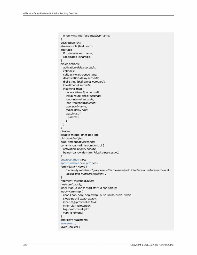
underlying-interface interface-name;}description text;etree-ac-role (leaf | root);interface {l2tp-interface-id name;(dedicated | shared);
}dialer-options {activation-delay seconds;callback;callback-wait-period time;deactivation-delay seconds;dial-string [dial-string-numbers];idle-timeout seconds;incoming-map {caller caller-id | accept-all;initial-route-check seconds;load-interval seconds;load-threshold percent;pool pool-name;redial-delay time;watch-list {[routes];
}}
}disable;disable-mlppp-inner-ppp-pfc;dlci dlci-identifier;drop-timeoutmilliseconds;dynamic-call-admission-control {activation-priority priority;bearer-bandwidth-limit kilobits-per-second;
}encapsulation type;epd-threshold cells plp1 cells;family family-name {... the family subhierarchy appears after the main [edit interfaces interface-name unitlogical-unit-number] hierarchy ...
}fragment-threshold bytes;host-prefix-only;inner-vlan-id-range start start-id end end-id;input-vlan-map {(pop | pop-pop | pop-swap | push | push-push | swap |swap-push | swap-swap);inner-tag-protocol-id tpid;inner-vlan-id number;tag-protocol-id tpid;vlan-id number;
}interleave-fragments;inverse-arp;layer2-policer {
Copyright © 2019, Juniper Networks, Inc.320
ATM Interfaces Feature Guide for Routing Devices

input-policer policer-name;input-three-color policer-name;output-policer policer-name;output-three-color policer-name;
}link-layer-overhead percent;minimum-links number;mrru bytes;multicast-dlci dlci-identifier;multicast-vci vpi-identifier.vci-identifier;multilink-max-classes number;multipoint;oam-liveness {up-count cells;down-count cells;
}oam-period (disable | seconds);output-vlan-map {(pop | pop-pop | pop-swap | push | push-push | swap |swap-push | swap-swap);inner-tag-protocol-id tpid;inner-vlan-id number;tag-protocol-id tpid;
}passive-monitor-mode;peer-unit unit-number;plp-to-clp;point-to-point;ppp-options {mru size;mtu (size | use-lower-layer);chap {access-profile name;default-chap-secret name;local-name name;passive;
}compression {acfc;pfc;
}dynamic-profile profile-name;ipcp-suggest-dns-option;lcp-restart-timermilliseconds;loopback-clear-timer seconds;ncp-restart-timermilliseconds;pap {access-profile name;default-pap-password password;local-name name;local-password password;passive;
}}pppoe-options {
321Copyright © 2019, Juniper Networks, Inc.
Chapter 8: Configuration Statements
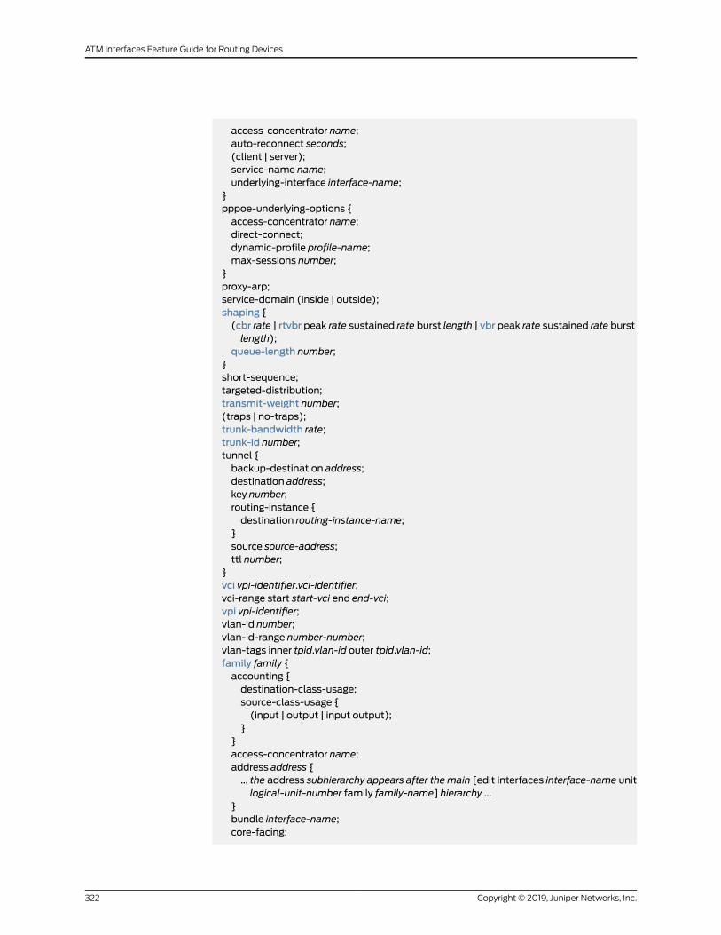
access-concentrator name;auto-reconnect seconds;(client | server);service-name name;underlying-interface interface-name;
}pppoe-underlying-options {access-concentrator name;direct-connect;dynamic-profile profile-name;max-sessions number;
}proxy-arp;service-domain (inside | outside);shaping {(cbr rate | rtvbr peak rate sustained rate burst length | vbr peak rate sustained rate burstlength);
queue-length number;}short-sequence;targeted-distribution;transmit-weight number;(traps | no-traps);trunk-bandwidth rate;trunk-id number;tunnel {backup-destination address;destination address;key number;routing-instance {destination routing-instance-name;
}source source-address;ttl number;
}vci vpi-identifier.vci-identifier;vci-range start start-vci end end-vci;vpi vpi-identifier;vlan-id number;vlan-id-range number-number;vlan-tags inner tpid.vlan-id outer tpid.vlan-id;family family {accounting {destination-class-usage;source-class-usage {(input | output | input output);
}}access-concentrator name;address address {... the address subhierarchy appears after the main [edit interfaces interface-name unitlogical-unit-number family family-name] hierarchy ...
}bundle interface-name;core-facing;
Copyright © 2019, Juniper Networks, Inc.322
ATM Interfaces Feature Guide for Routing Devices
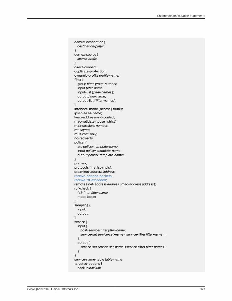
demux-destination {destination-prefix;
}demux-source {source-prefix;
}direct-connect;duplicate-protection;dynamic-profile profile-name;filter {group filter-group-number;input filter-name;input-list [filter-names];output filter-name;output-list [filter-names];
}interface-mode (access | trunk);ipsec-sa sa-name;keep-address-and-control;mac-validate (loose | strict);max-sessions number;mtu bytes;multicast-only;no-redirects;policer {arp policer-template-name;input policer-template-name;output policer-template-name;
}primary;protocols [inet isompls];proxy inet-address address;receive-options-packets;receive-ttl-exceeded;remote (inet-address address | mac-address address);rpf-check {fail-filter filter-namemode loose;
}sampling {input;output;
}service {input {post-service-filter filter-name;service-set service-set-name <service-filter filter-name>;
}output {service-set service-set-name <service-filter filter-name>;
}}service-name-table table-nametargeted-options {backup backup;
323Copyright © 2019, Juniper Networks, Inc.
Chapter 8: Configuration Statements

group group;primary primary;weight ($junos-interface-target-weight |weight-value);
}(translate-discard-eligible | no-translate-discard-eligible);(translate-fecn-and-becn | no-translate-fecn-and-becn);translate-plp-control-word-de;unnumbered-address interface-namedestinationaddressdestination-profileprofile-name;vlan-id number;vlan-id-list [number number-number];address address {arp ip-address (mac | multicast-mac)mac-address <publish>;broadcast address;destination address;destination-profile name;eui-64;master-only;multipoint-destination address {dlci dlci-identifier;epd-threshold cells <plp1 cells>;inverse-arp;oam-liveness {up-count cells;down-count cells;
}oam-period (disable | seconds);shaping {(cbr rate | rtvbr burst length peak rate sustained rate | vbr burst length peak ratesustained rate);
queue-length number;}vci vpi-identifier.vci-identifier;
}preferred;primary;(vrrp-group | vrrp-inet6-group) group-number {(accept-data | no-accept-data);advertise–interval seconds;authentication-type authentication;authentication-key key;fast-intervalmilliseconds;(preempt | no-preempt) {hold-time seconds;
}priority number;track {interface interface-name {bandwidth-threshold bits-per-second priority-cost number;
}priority-hold-time seconds;route ip-address/prefix-length routing-instance instance-name priority-cost cost;
}virtual-address [addresses];virtual-link-local-address ipv6–address;vrrp-inherit-from {
Copyright © 2019, Juniper Networks, Inc.324
ATM Interfaces Feature Guide for Routing Devices

active-interface interface-name;active-group group-number;
}}
}}
}
Hierarchy Level [edit interfaces interface-name],[edit logical-systems logical-system-name interfaces interface-name],[edit interfaces interface-set interface-set-name interface interface-name]
Release Information Statement introduced before Junos OS Release 7.4.
Range increased for static pseudowire interfaces to 1,073,741,823 in Junos OS Release
18.3R1.
Description Configure a logical interfaceon thephysical device. Youmust configure a logical interface
to be able to use the physical device.
Options logical-unit-number—Number of the logical unit.
Range: 0 through 1,073,741,823 for demux, PPPoE, and pseudowire static interfaces. 0through 16,385 for all other static interface types.
etree-ac-role (leaf | root)—To configure an interface as either leaf or root.
The remaining statementsareexplainedseparately. Search for a statement inCLIExplorer
or click a linked statement in the Syntax section for details.
Required PrivilegeLevel
interface—To view this statement in the configuration.
interface-control—To add this statement to the configuration.
RelatedDocumentation
• Configuring Logical Interface Properties on page 158
• Junos OS Services Interfaces Library for Routing Devices
325Copyright © 2019, Juniper Networks, Inc.
Chapter 8: Configuration Statements

use-null-cw
Syntax use-null-cw;
Hierarchy Level [edit interfaces interface-name atm-options]
Release Information Statement introduced in Junos OS Release 8.3.
Description Insert (for sending traffic) or strip (for receiving traffic) a null control word in MPLS
packets when an MPLS Layer 2 circuit is configured with cell transport mode on a router
running Junos OS Release 8.3 or later. When cell relay transport mode is configured, the
use-null-cw statementallows interoperability between routers running JunosOSRelease
8.2 and earlier and those running Junos OS Release 8.3 and later.
NOTE: Theuse-null-cw statement is supportedonlyon routers running Junos
OS Release 8.3 or later.
Required PrivilegeLevel
interface—To view this statement in the configuration.
interface-control—To add this statement to the configuration.
RelatedDocumentation
• Configuring Layer 2 Circuit Transport Mode on page 54
Copyright © 2019, Juniper Networks, Inc.326
ATM Interfaces Feature Guide for Routing Devices

up-count
Syntax up-count cells;
Hierarchy Level [edit interfaces interface-name atm-options vpi vpi-identifier oam-liveness],[edit interfaces interface-name unit logical-unit-number oam-liveness],[edit interfaces interface-name unit logical-unit-number family family address addressmultipoint-destination address oam-liveness],
[edit logical-systems logical-system-name interfaces interface-nameunit logical-unit-numberoam-liveness],
[edit logical-systems logical-system-name interfaces interface-nameunit logical-unit-numberfamily family address addressmultipoint-destination address oam-liveness]
Release Information Statement introduced before Junos OS Release 7.4.
Description For ATM encapsulation only, configure Operation, Administration, and Maintenance
(OAM)F5 loopbackcell count thresholds.Not supportedonATM-over-SHDSL interfaces.
For ATM2 IQ PICs only, configure OAM F4 loopback cell count thresholds at the [edit
interfaces interface-name atm-options vpi vpi-identifier] hierarchy level.
Options cells—Minimum number of consecutive OAM F4 or F5 loopback cells received before a
VC is declared up.
Range: 1 through 255
Default: 5 cells
Required PrivilegeLevel
interface—To view this statement in the configuration.
interface-control—To add this statement to the configuration.
RelatedDocumentation
• Configuring the ATMOAM F5 Loopback Cell Threshold on page 86
327Copyright © 2019, Juniper Networks, Inc.
Chapter 8: Configuration Statements

vbr
Syntax vbr peak rate sustained rate burst length;
Hierarchy Level [edit interfaces interface-name atm-options vpi vpi-identifier shaping],[edit interfaces interface-name unit logical-unit-number address address family familymultipoint-destination address shaping ],
[edit interfaces interface-name unit logical-unit-number shaping ],[edit logical-systems logical-system-name interfaces interface-nameunit logical-unit-numberaddress address family familymultipoint-destination address shaping ],
[edit logical-systems logical-system-name interfaces interface-nameunit logical-unit-numbershaping ]
Release Information Statement introduced before Junos OS Release 7.4.
Description ForATMencapsulationonly, define thevariablebandwidthutilization in the traffic-shaping
profile.
When you configure the variable bandwidth utilization, youmust specify all threeoptions
(burst, peak, and sustained). You can specify the rate in bits per second either as a
completedecimalnumberorasadecimalnumber followedby theabbreviationk (1000),
m (1,000,000), or g (1,000,000,000). You can also specify the rate in cells per second
by entering a decimal number followed by the abbreviation c; values expressed in cells
per second are converted to bits per second bymeans of the formula 1 cps = 384 bps.
Default If the vbr statement is not specified, bandwidth utilization is unlimited.
Options burst length—Burst length, in cells. If you set the length to 1, the peak traffic rate is used.
Range: 1 through 4000 cells
peak rate—Peak rate, in bits per second or cells per second.
Range: For ATM1 interfaces, 33 Kbps through 135.6 Mbps (ATMOC3); 33 Kbps through
276 Mbps (ATMOC12). For ATM2 IQ OC3 and OC12 interfaces, 33 Kbps through
542,526,792 bps. For ATM2 IQ OC48 interfaces, 33 Kbps through 2,170,107,168 bps.
For ATM2 IQDS3 and E3 interfaces, from 33 Kbps through themaximum rate, which
depends on the ATM encapsulation and framing you configure.
sustained rate—Sustained rate, in bits per second or cells per second.
Range: For ATM1 interfaces, 33 Kbps through 135.6 Mbps (ATMOC3); 33 Kbps through
276 Mbps (ATMOC12). For ATM2 IQ OC3 and OC12 interfaces, 33 Kbps through
542,526,792 bps. For ATM2 IQ OC48 interfaces, 33 Kbps through 2,170,107,168 bps.
For ATM2 IQDS3 and E3 interfaces, from 33 Kbps through themaximum rate, which
depends on the ATM encapsulation and framing you configure.
Copyright © 2019, Juniper Networks, Inc.328
ATM Interfaces Feature Guide for Routing Devices
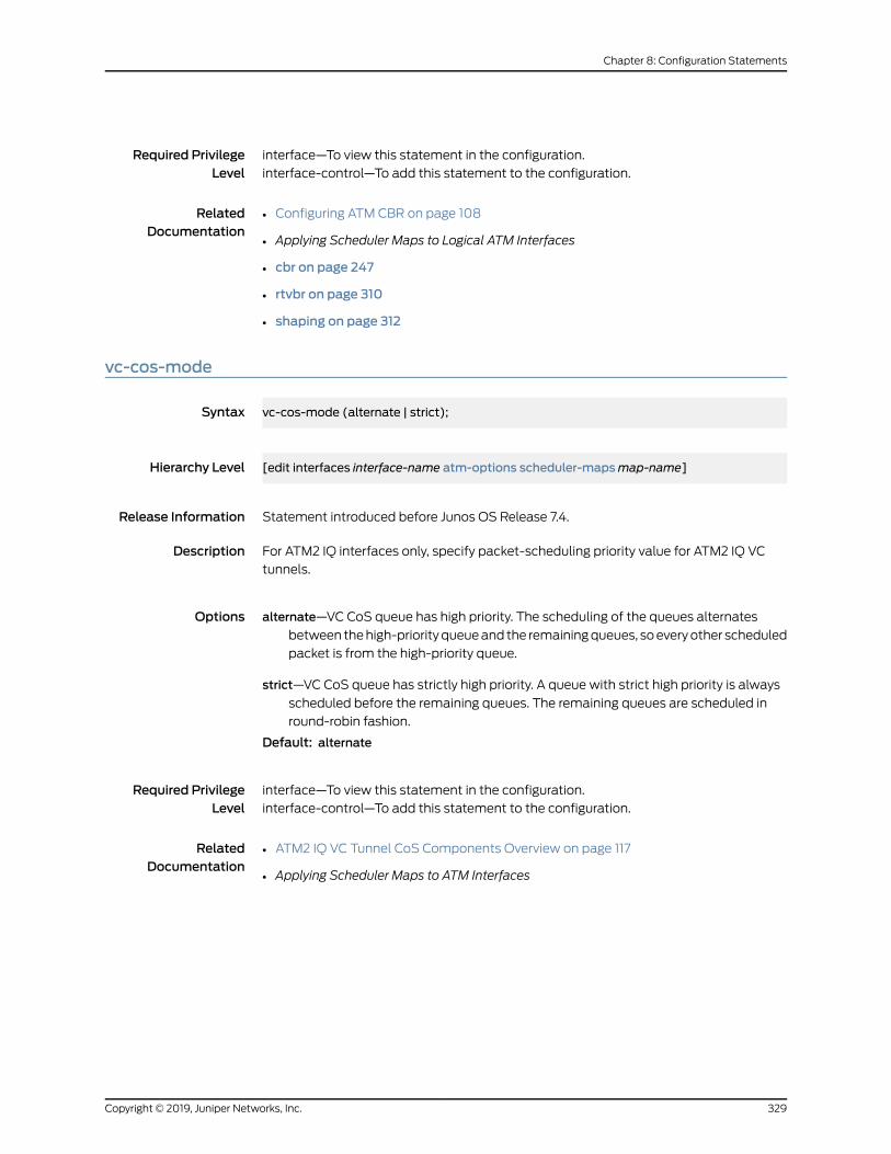
Required PrivilegeLevel
interface—To view this statement in the configuration.
interface-control—To add this statement to the configuration.
RelatedDocumentation
• Configuring ATM CBR on page 108
• Applying Scheduler Maps to Logical ATM Interfaces
• cbr on page 247
• rtvbr on page 310
• shaping on page 312
vc-cos-mode
Syntax vc-cos-mode (alternate | strict);
Hierarchy Level [edit interfaces interface-name atm-options scheduler-mapsmap-name]
Release Information Statement introduced before Junos OS Release 7.4.
Description For ATM2 IQ interfaces only, specify packet-scheduling priority value for ATM2 IQ VC
tunnels.
Options alternate—VC CoS queue has high priority. The scheduling of the queues alternates
between thehigh-priorityqueueand the remainingqueues, soeveryother scheduled
packet is from the high-priority queue.
strict—VC CoS queue has strictly high priority. A queue with strict high priority is always
scheduled before the remaining queues. The remaining queues are scheduled in
round-robin fashion.
Default: alternate
Required PrivilegeLevel
interface—To view this statement in the configuration.
interface-control—To add this statement to the configuration.
RelatedDocumentation
• ATM2 IQ VC Tunnel CoS Components Overview on page 117
• Applying Scheduler Maps to ATM Interfaces
329Copyright © 2019, Juniper Networks, Inc.
Chapter 8: Configuration Statements

vci
Syntax vci vpi-identifier.vci-identifier;
Hierarchy Level [edit interfaces at-fpc/pic/port unit logical-unit-number],[edit interfaces at-fpc/pic/port unit logical-unit-number family family address addressmultipoint-destination address],
[edit logical-systems logical-system-name interfacesat-fpc/pic/portunit logical-unit-number],[edit logical-systems logical-system-name interfacesat-fpc/pic/portunit logical-unit-numberfamily family address addressmultipoint-destination address]
Release Information Statement introduced before Junos OS Release 7.4.
Statement introduced in Junos OS Release 11.1 for the QFX Series.
Statement introduced in JunosOSRelease 12.2 for theACXSeriesUniversalMetro routers.
Description For ATMpoint-to-point logical interfaces only, configure the virtual circuit identifier (VCI)
and virtual path identifier (VPI).
To configure a VPI for a point-to-multipoint interface, specify the VPI in the
multipoint-destination statement.
VCIs 0 through 31 are reserved for specific ATM values designated by the ATM Forum.
Options vci-identifier—ATM virtual circuit identifier. Unless you configure the interface to use
promiscuous mode, this value cannot exceed the highest-numbered VC configured
for the interface with themaximum-vcs option of the vpi statement.
Range: 0 through 4089 or 0 through 65,535 with promiscuous mode, with VCIs0 through 31 reserved.
vpi-identifier—ATM virtual path identifier.
Range: 0 through 255
Default: 0
Required PrivilegeLevel
interface—To view this statement in the configuration.
interface-control—To add this statement to the configuration.
RelatedDocumentation
• Configuring a Point-to-Point ATM1 or ATM2 IQ Connection on page 115
• Applying Scheduler Maps to Logical ATM Interfaces
Copyright © 2019, Juniper Networks, Inc.330
ATM Interfaces Feature Guide for Routing Devices

vpi (ATMCCC Cell-Relay PromiscuousMode)
Syntax vpi vpi-identifier;
Hierarchy Level [edit interfaces at-fpc/pic/port atm-options promiscuous-mode]
Release Information Statement introduced before Junos OS Release 7.4.
Junos OS Release 12.2 for the ACX Series Universal Metro routers.
Description For ATM interfaces, allow all VCIs in this VPI to open in ATM CCC cell-relay mode.
When you include vpi statements at the [edit interfaces interface-name atm-options
promiscuous-mode] hierarchy level, the specified VPIs open in promiscuous mode.
Options vpi-identifier—ATM virtual path identifier. This is one of the VPIs that you define in the vcistatement. (For a list of hierarchy levels at which you can include the vci statement,
see vci.)
Range: 0 through 255
Required PrivilegeLevel
interface—To view this statement in the configuration.
interface-control—To add this statement to the configuration.
RelatedDocumentation
• Configuring ATM Cell-Relay Promiscuous Mode on page 42
331Copyright © 2019, Juniper Networks, Inc.
Chapter 8: Configuration Statements

vpi (Define Virtual Path)
Syntax vpi vpi-identifier {maximum-vcsmaximum-vcs;oam-liveness {up-count cells;down-count cells;
}oam-period (disable | seconds);shaping {(cbr rate | rtvbr peak rate sustained rate burst length | vbr peak rate sustained rate burstlength);
queue-length number;}
}
Hierarchy Level [edit interfaces at-fpc/pic/port atm-options]
Release Information Statement introduced before Junos OS Release 7.4.
Description For ATM interfaces, configure the virtual path (VP).
NOTE: Certain options apply only to specific platforms.
Options vpi-identifier—ATM virtual path identifier. This is one of the VPIs that you define in the vcistatement. (For a list of hierarchy levels at which you can include the vci statement,
see vci.)
Range: 0 through 255
The remaining statementsareexplainedseparately. Search for a statement inCLIExplorer
or click a linked statement in the Syntax section for details.
Required PrivilegeLevel
interface—To view this statement in the configuration.
interface-control—To add this statement to the configuration.
RelatedDocumentation
• Configuring the MaximumNumber of ATM1 VCs on a VP on page 46
Copyright © 2019, Juniper Networks, Inc.332
ATM Interfaces Feature Guide for Routing Devices

vpi (Logical Interface and Interworking)
Syntax vpi virtual-path-identifier;
Hierarchy Level [edit interfaces at-fpc/pic/port unit logical-unit-number],[edit logical-systems logical-system-name interfacesat-fpc/pic/portunit logical-unit-number]
Release Information Statement introduced in Junos OS Release 9.0.
Statement introduced in JunosOSRelease 12.2 for theACXSeriesUniversalMetro routers.
Description VPI used in an ATM-to-Ethernet interworking cross-connect.
Options virtual-path-identifier—VPI to be used.
Range: 0 through 255
Required PrivilegeLevel
interface—To view this statement in the configuration.
interface-control—To add this statement to the configuration.
RelatedDocumentation
• Configuring ATM-to-Ethernet Interworking
• Configuring ATM Cell-Relay Promiscuous Mode on page 42
working-circuit
Syntax working-circuit group-name;
Hierarchy Level [edit interfaces interface-name sonet-options aps]
Release Information Statement introduced before Junos OS Release 7.4.
Description Configure the working router in an APS circuit pair.
Options group-name—Circuit’s group name.
Required PrivilegeLevel
interface—To view this statement in the configuration.
interface-control—To add this statement to the configuration.
RelatedDocumentation
• Configuring Basic Automatic Protect Switching
• protect-circuit on page 303
333Copyright © 2019, Juniper Networks, Inc.
Chapter 8: Configuration Statements
z0-increment
Syntax (z0-increment | no-z0-increment);
Hierarchy Level [edit interfaces interface-name sonet-options]
Release Information Statement introduced before Junos OS Release 7.4.
Description Configure an incremental STM ID rather than a static one.
Default no-Z0-increment
Required PrivilegeLevel
interface—To view this statement in the configuration.
interface-control—To add this statement to the configuration.
RelatedDocumentation
• Configuring an Incrementing STM ID to Interoperate with Older Equipment in SDHMode
• sonet-options
Copyright © 2019, Juniper Networks, Inc.334
ATM Interfaces Feature Guide for Routing Devices

CHAPTER 9
Operational Commands
• clear ilmi statistics
• ping atm
• show class-of-service
• show class-of-service forwarding-class
• show ilmi
• show ilmi statistics
• show interfaces (ATM)
335Copyright © 2019, Juniper Networks, Inc.

clear ilmi statistics
Syntax clear ilmi statistics
Release Information Command introduced before Junos OS Release 7.4.
Description Set Integrated Local Management Interface (ILMI) statistics to zero.
Options This command has no options.
Required PrivilegeLevel
clear
RelatedDocumentation
show ilmi statistics on page 346•
List of Sample Output clear ilmi statistics on page 336
Output Fields When you enter this command, you are provided feedback on the status of your request.
Sample Output
clear ilmi statistics
user@host> clear ilmi statistics
Copyright © 2019, Juniper Networks, Inc.336
ATM Interfaces Feature Guide for Routing Devices
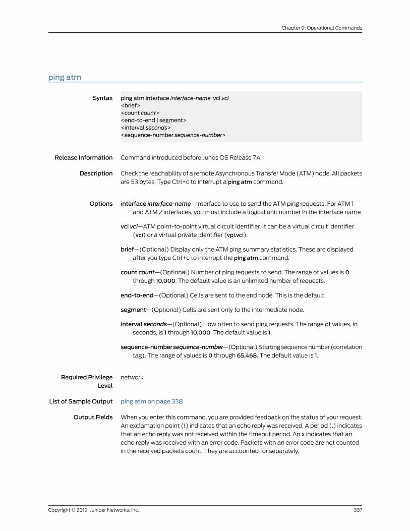
ping atm
Syntax ping atm interface interface-name vci vci<brief><count count><end-to-end | segment><interval seconds><sequence-number sequence-number>
Release Information Command introduced before Junos OS Release 7.4.
Description Check the reachability of a remoteAsynchronousTransferMode (ATM)node. All packets
are 53 bytes. Type Ctrl+c to interrupt a ping atm command.
Options interface interface-name—Interface to use to send the ATM ping requests. For ATM 1
and ATM 2 interfaces, youmust include a logical unit number in the interface name
vci vci—ATM point-to-point virtual circuit identifier. It can be a virtual circuit identifier
(vci) or a virtual private identifier (vpi.vci).
brief—(Optional) Display only the ATM ping summary statistics. These are displayed
after you type Ctrl+c to interrupt the ping atm command.
count count—(Optional) Number of ping requests to send. The range of values is 0through 10,000. The default value is an unlimited number of requests.
end-to-end—(Optional) Cells are sent to the end node. This is the default.
segment—(Optional) Cells are sent only to the intermediate node.
interval seconds—(Optional) How often to send ping requests. The range of values, in
seconds, is 1 through 10,000. The default value is 1.
sequence-numbersequence-number—(Optional)Startingsequencenumber(correlationtag). The range of values is 0 through 65,468. The default value is 1.
Required PrivilegeLevel
network
List of Sample Output ping atm on page 338
Output Fields When you enter this command, you are provided feedback on the status of your request.
An exclamation point (!) indicates that an echo reply was received. A period (.) indicates
that an echo reply was not received within the timeout period. An x indicates that an
echo reply was received with an error code. Packets with an error code are not counted
in the received packets count. They are accounted for separately.
337Copyright © 2019, Juniper Networks, Inc.
Chapter 9: Operational Commands
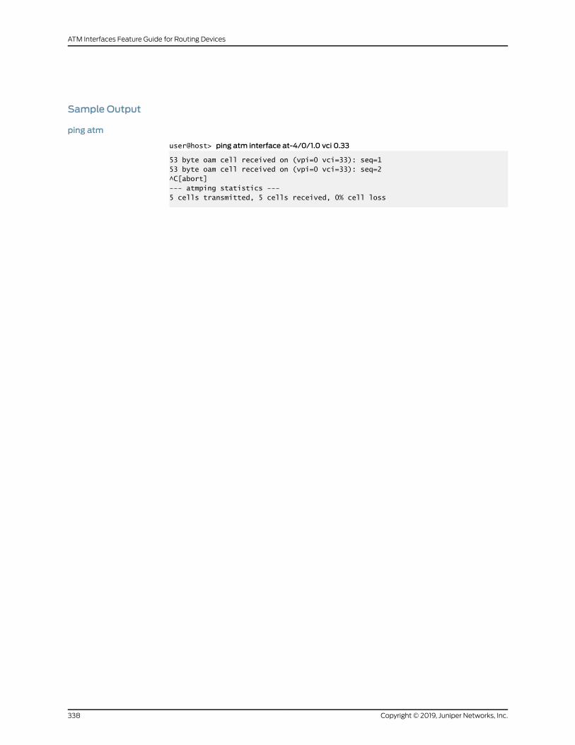
Sample Output
ping atm
user@host> ping atm interface at-4/0/1.0 vci 0.33
53 byte oam cell received on (vpi=0 vci=33): seq=153 byte oam cell received on (vpi=0 vci=33): seq=2^C[abort]--- atmping statistics ---5 cells transmitted, 5 cells received, 0% cell loss
Copyright © 2019, Juniper Networks, Inc.338
ATM Interfaces Feature Guide for Routing Devices

show class-of-service
Syntax show class-of-service
Release Information Command introduced before Junos OS Release 7.4.
Command introduced in Junos OS Release 9.0 for EX Series switches.
Description Display theentire class-of-service (CoS)configuration, including system-chosendefaults.
Executing this command is equivalent to executing all show class-of-service commands
in succession.
Options This command has no options.
Required PrivilegeLevel
view
List of Sample Output show class-of-service on page 339
Output Fields See the output field descriptions for the commands.
Sample Output
show class-of-service
user@host> show class-of-service
Forwarding class Queue best-effort 0 expedited-forwarding 1 assured-forwarding 2 network-control 3Code point type: dscp Alias Bit pattern af11 001010 af12 001100 af13 001110 ...Code point type: dscp-ipv6 Alias Bit pattern af11 001010 af12 001100 af13 001110 ...Code point type: exp Alias Bit pattern af11 100 af12 101 be 000 ...Code point type: ieee-802.1 Alias Bit pattern af11 100
339Copyright © 2019, Juniper Networks, Inc.
Chapter 9: Operational Commands

af12 101 be 000 ...Classifier: dscp-default, Code point type: dscp, Index: 6 Code point Forwarding class Loss priority 000000 best-effort low 000001 best-effort low 000010 best-effort low ....Classifier: dscp-ipv6-default, Code point type: dscp-ipv6, Index: 7 Code point Forwarding class Loss priority 000000 best-effort low 000001 best-effort low 000010 best-effort low ...Loss-priority-map: frame-relay-de-default, Code point type: frame-relay-de, Index: 12 Code point Loss priority 0 low 1 high
Rewrite rule: dscp-default, Code point type: dscp, Index: 23 Forwarding class Loss priority Code point best-effort low 000000 best-effort high 000000 expedited-forwarding low 101110 ...Rewrite rule: dscp-ipv6-default, Code point type: dscp-ipv6, Index: 24 Forwarding class Loss priority Code point best-effort low 000000 best-effort high 000000 .......Drop profile: <default-drop-profile>, Type: discrete, Index: 1 Fill level Drop probability 100 100
Scheduler map: <default>, Index: 2
Scheduler: <default-be>, Forwarding class: best-effort, Index: 16 Transmit rate: 95 percent, Rate Limit: none, Buffer size: 95 percent, Priority: low Drop profiles: Loss priority Protocol Index Name Low any 1 <default-drop-profile> Medium low any 1 <default-drop-profile> Medium high any 1 <default-drop-profile> High any 1 <default-drop-profile> ...Physical interface: fe-0/0/0, Index: 137Queues supported: 8, Queues in use: 4 Scheduler map: <default>, Index: 2
Logical interface: fe-0/0/0.0, Index: 69 Object Name Type Index Adaptive-shaper fr-shaper 35320 Classifier ipprec-compatibility ip 11
Physical interface: fe-0/0/1, Index: 138Queues supported: 8, Queues in use: 4
Copyright © 2019, Juniper Networks, Inc.340
ATM Interfaces Feature Guide for Routing Devices

Scheduler map: <default>, Index: 2...
341Copyright © 2019, Juniper Networks, Inc.
Chapter 9: Operational Commands
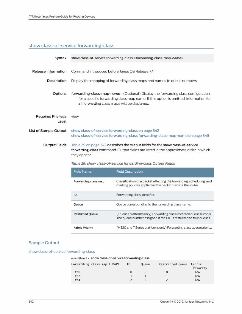
show class-of-service forwarding-class
Syntax show class-of-service forwarding-class <forwarding-class-map-name>
Release Information Command introduced before Junos OS Release 7.4.
Description Display the mapping of forwarding class maps and names to queue numbers.
Options forwarding-class-map-name—(Optional) Display the forwarding class configurationfor a specific forwarding class map name. If this option is omitted, information for
all forwarding class maps will be displayed.
Required PrivilegeLevel
view
List of Sample Output show class-of-service forwarding-class on page 342show class-of-service forwarding-class forwarding-class-map-name on page 343
Output Fields Table 29 on page 342 describes the output fields for the show class-of-service
forwarding-class command. Output fields are listed in the approximate order in which
they appear.
Table 29: show class-of-service forwarding-class Output Fields
Field DescriptionField Name
Classification of a packet affecting the forwarding, scheduling, andmarking policies applied as the packet transits the router.
Forwarding classmap
Forwarding class identifier.ID
Queue corresponding to the forwarding class name.Queue
(TSeriesplatformsonly) Forwardingclass restrictedqueuenumber.The queue number assigned if the PIC is restricted to four queues.
Restricted Queue
(M320andTSeriesplatformsonly) Forwarding classqueuepriority.Fabric Priority
Sample Output
show class-of-service forwarding-class
user@host> show class-of-service forwarding-class
Forwarding class map FCMAP1 ID Queue Restricted queue Fabric Priority fc0 0 0 0 low fc2 1 1 1 low fc4 2 2 2 low
Copyright © 2019, Juniper Networks, Inc.342
ATM Interfaces Feature Guide for Routing Devices

fc6 3 3 3 low fc1 4 0 0 low fc3 5 1 1 low fc5 6 2 2 low fc7 7 3 3 low fc8 8 4 0 low fc9 9 4 0 low fc10 10 5 1 low fc11 11 5 1 low fc12 12 6 2 low fc13 13 6 2 low fc14 14 7 3 low fc15 15 7 3 low
Sample Output
show class-of-service forwarding-classforwarding-class-map-name
user@host> show class-of-service forwarding-class FCMAP1
Forwarding class map FCMAP1 ID Queue Restricted queue Fabric Priority fc0 0 0 0 low fc2 1 1 1 low fc4 2 2 2 low fc6 3 3 3 low fc1 4 0 0 low fc3 5 1 1 low fc5 6 2 2 low fc7 7 3 3 low fc8 8 4 0 low fc9 9 4 0 low fc10 10 5 1 low fc11 11 5 1 low fc12 12 6 2 low fc13 13 6 2 low fc14 14 7 3 low fc15 15 7 3 low
343Copyright © 2019, Juniper Networks, Inc.
Chapter 9: Operational Commands

show ilmi
Syntax show ilmi<all | interface interface-name>
Release Information Command introduced before Junos OS Release 7.4.
Description Display Integrated Local Management Interface (ILMI) information.
Options none—Display information for all ILMI-enabled ATM devices.
all | interface interface-name—(Optional) Display IP addresses and port names for allILMI-enabled ATM devices or for a particular device.
Required PrivilegeLevel
view
List of Sample Output show ilmi all on page 344show ilmi interface on page 345
Output Fields Table 30onpage344 lists the output fields for the show ilmi command.Output fields are
listed in the approximate order in which they appear.
Table 30: show ilmi Output Fields
Field DescriptionField Name
Name of the physical interface.Physical interface
Virtual connection identifier.VCI
IP address of the peer.Peer IP address
Port interface name of the peer.Peer interface name
Sample Output
show ilmi all
user@host> show ilmi all
Physical interface: at-6/2/1, VCI: 0.16 Peer IP address: 192.168.4.24, Peer interface name: 1C4 Physical interface: at-6/3/0, VCI: 0.16 Peer IP address: 192.168.7.6, Peer interface name: 2C3 Physical interface: at-6/4/0, VCI: 0.16 Peer IP address: 192.168.9.10, Peer interface name: 1C2
Copyright © 2019, Juniper Networks, Inc.344
ATM Interfaces Feature Guide for Routing Devices

show ilmi interface
user@host> show ilmi interface at-6/2/1
Physical interface: at-6/2/1, VCI: 0.16 Peer IP address: 192.168.4.24, Peer interface name: 1C4
345Copyright © 2019, Juniper Networks, Inc.
Chapter 9: Operational Commands

show ilmi statistics
Syntax show ilmi statistics
Release Information Command introduced before Junos OS Release 7.4.
Description Display input and output Integrated Local Management Interface (ILMI) statistics.
Options This command has no options.
Required PrivilegeLevel
view
RelatedDocumentation
clear ilmi statistics on page 336•
List of Sample Output show ilmi statistics on page 348
Output Fields Table 31 on page 347 lists the output fields for the show ilmi statistics command. Output
fields are listed in the approximate order in which they appear.
Copyright © 2019, Juniper Networks, Inc.346
ATM Interfaces Feature Guide for Routing Devices

Table 31: show ilmi statistics Output Fields
Field DescriptionFieldName
Information about received ILMI packets:
• Packets—Total number of messages delivered to the ILMI entity from the transport service.
• Bad versions—Total number of messages delivered to the ILMI entity that were for an unsupported ILMI version.
• Bad community names—Total number ofmessages delivered to the ILMI entity that did not use an ILMI communityname.
• Bad community uses—Total number of messages delivered to the ILMI entity that represented an ILMI operationthat was not allowed by the ILMI community named in the message.
• ASNparse errors—Total number of ASN.1 or BER errors encountered by the ILMI entity when decoding received ILMImessages.
• Too bigs—Total number of ILMI packets delivered to the ILMI entity with an error status field of tooBig.
• Nosuchnames—Total number of ILMI packets delivered to the ILMI entity with an error status field of noSuchName.
• Bad values—Total number of ILMI packets delivered to the ILMI entity with an error status field of badValue.
• Read onlys—Total number of valid ILMI packets delivered to the ILMI entity with an error status field of readOnly.Only incorrect implementations of ILMI generate this error.
• General errors—Total number of ILMI packets delivered to the ILMI entity with an error status field of genErr.
• Total request varbinds—Total number of objects retrieved successfully by the ILMI entity as a result of receivingvalid ILMI GetRequest and GetNext packets.
• Total set varbinds—Total number of objects modified successfully by the ILMI entity as a result of receiving validILMI SetRequest packets.
• Get requests—Total number of ILMIGetRequest packets that have been accepted and processed by the ILMI entity.
• Get nexts—Total number of ILMI GetNext packets that have been accepted and processed by the ILMI entity.
• Set requests—Total number of ILMI SetRequest packets that have been accepted and processed by the ILMI entity.
• Get responses—Total number of ILMI GetResponse packets that have been accepted and processed by the ILMIentity.
• Traps—Total number of ILMI traps received by the ILMI entity.
• Silent drops—Total number of GetRequest, GetNextRequest, GetBulkRequest, SetRequest, and InformRequestpackets delivered to the ILMI entity that were silently dropped because the size of a reply containing an alternateresponse packet with an empty variable-bindings field was greater than either a local constraint or the maximummessage size associated with the originator of the requests.
• Proxy drops—Total number of GetRequest, GetNextRequest, GetBulkRequest, SetRequest, and InformRequestpacketsdelivered to the ILMIentity thatweresilentlydroppedbecause the transmissionof the (possibly translated)message to a proxy target failed in such a way (other than a timeout) that no response packet could be returned.
Input
Information about transmitted ILMI packets:
• Packets—Total number of messages passed from the ILMI entity to the transport service.
• Too bigs—Total number of ILMI packets generated by the ILMI entity with an error status field of tooBig.
• Nosuchnames—Total numberof ILMIpackets generatedby the ILMI entitywithanerror status fieldofnoSuchName.
• Bad values—Total number of ILMI packets generated by the ILMI entity with an error status field of badValue.
• General errors—Total number of ILMI packets generated by the ILMI entity with an error status field of genErr.
• Get requests—Total number of ILMI GetRequest packets that have been generated by the ILMI entity.
• Get nexts—Total number of ILMI GetNext packets that have been generated by the ILMI entity.
• Set requests—Total number of ILMI SetRequest packets that have been generated by the ILMI entity.
• Get responses—Total number of ILMI GetResponse packets that have been generated by the ILMI entity.
• Traps—Total number of ILMI traps generated by the ILMI entity.
Output
347Copyright © 2019, Juniper Networks, Inc.
Chapter 9: Operational Commands

Sample Output
show ilmi statistics
user@host> show ilmi statistics
ILMI statistics: Input: Packets: 0, Bad versions: 0, Bad community names: 0, Bad community uses: 0, ASN parse errors: 0, Too bigs: 0, No such names: 0, Bad values: 0, Read onlys: 0, General errors: 0, Total request varbinds: 0, Total set varbinds: 0, Get requests: 0, Get nexts: 0, Set requests: 0, Get responses: 0, Traps: 0, Silent drops: 0, Proxy drops 0 Output: Packets: 0, Too bigs: 0, No such names: 0, Bad values: 0, General errors: 0, Get requests: 0, Get nexts: 0, Set requests: 0, Get responses: 0, Traps: 0
Copyright © 2019, Juniper Networks, Inc.348
ATM Interfaces Feature Guide for Routing Devices

show interfaces (ATM)
Syntax show interfaces at-fpc/pic/port<brief | detail | extensive | terse><descriptions><media><snmp-index snmp-index><statistics>
Release Information Command introduced before Junos OS Release 7.4.
Description (M Series and T Series routers only) Display status information about the specified ATM
interface.
Options at-fpc/pic/port—Display standard information about the specified ATM interface.
brief | detail | extensive | terse—(Optional) Display the specified level of output.
descriptions—(Optional) Display interface description strings.
media—(Optional) Display media-specific information about network interfaces.
snmp-index snmp-index—(Optional) Display the SNMP index of the interface.
statistics—(Optional) Display static interface statistics.
Required PrivilegeLevel
view
List of Sample Output show interfaces (ATM, IMAGroup) on page 364show interfaces extensive (ATM IMAGroup) on page 365show interfaces (ATM1, SONETMode) on page 366show interfaces brief (ATM1, SONETMode) on page 367show interfaces detail (ATM1, SONETMode) on page 367show interfaces extensive (ATM1, SONETMode) on page 368show interfaces (ATM2, SDHMode) on page 371show interfaces brief (ATM2, SDHMode) on page 371show interfaces detail (ATM2, SDHMode) on page 372show interfaces extensive (ATM2, SDHMode) on page 374show interfaces (ATM2, SONETMode) on page 376show interfaces brief (ATM2, SONETMode) on page 378show interfaces detail (ATM2, SONETMode) on page 378show interfaces extensive (ATM2, SONETMode) on page 381
Output Fields Table 32 on page 350 lists the output fields for the show interfaces (ATM) command.
Output fields are listed in the approximate order in which they appear.
349Copyright © 2019, Juniper Networks, Inc.
Chapter 9: Operational Commands
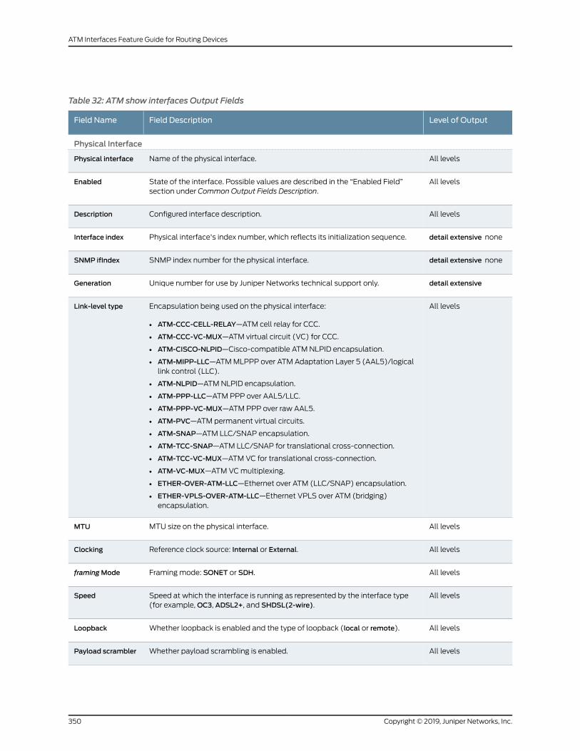
Table 32: ATM show interfaces Output Fields
Level of OutputField DescriptionField Name
Physical Interface
All levelsName of the physical interface.Physical interface
All levelsState of the interface. Possible values are described in the “Enabled Field”section under Common Output Fields Description.
Enabled
All levelsConfigured interface description.Description
detail extensive nonePhysical interface's index number, which reflects its initialization sequence.Interface index
detail extensive noneSNMP index number for the physical interface.SNMP ifIndex
detail extensiveUnique number for use by Juniper Networks technical support only.Generation
All levelsEncapsulation being used on the physical interface:
• ATM-CCC-CELL-RELAY—ATM cell relay for CCC.
• ATM-CCC-VC-MUX—ATM virtual circuit (VC) for CCC.
• ATM-CISCO-NLPID—Cisco-compatible ATM NLPID encapsulation.
• ATM-MIPP-LLC—ATMMLPPP over ATM Adaptation Layer 5 (AAL5)/logicallink control (LLC).
• ATM-NLPID—ATMNLPID encapsulation.
• ATM-PPP-LLC—ATM PPP over AAL5/LLC.
• ATM-PPP-VC-MUX—ATM PPP over raw AAL5.
• ATM-PVC—ATM permanent virtual circuits.
• ATM-SNAP—ATM LLC/SNAP encapsulation.
• ATM-TCC-SNAP—ATM LLC/SNAP for translational cross-connection.
• ATM-TCC-VC-MUX—ATM VC for translational cross-connection.
• ATM-VC-MUX—ATM VCmultiplexing.
• ETHER-OVER-ATM-LLC—Ethernet over ATM (LLC/SNAP) encapsulation.
• ETHER-VPLS-OVER-ATM-LLC—Ethernet VPLS over ATM (bridging)encapsulation.
Link-level type
All levelsMTU size on the physical interface.MTU
All levelsReference clock source: Internal or External.Clocking
All levelsFramingmode: SONET or SDH.framingMode
All levelsSpeed at which the interface is running as represented by the interface type(for example,OC3, ADSL2+, and SHDSL(2-wire).
Speed
All levelsWhether loopback is enabled and the type of loopback (local or remote).Loopback
All levelsWhether payload scrambling is enabled.Payload scrambler
Copyright © 2019, Juniper Networks, Inc.350
ATM Interfaces Feature Guide for Routing Devices

Table 32: ATM show interfaces Output Fields (continued)
Level of OutputField DescriptionField Name
All levelsInformation about the physical device. Possible values are described in the“Device Flags” section under Common Output Fields Description.
Device flags
All levelsInformation about the link. Possible values are described in the “Link Flags”section under Common Output Fields Description.
Link flags
detail extensive noneNumber of CoS queues configured.CoS queues
detail extensiveCurrent interface hold-time up and hold-time down, in milliseconds.Hold-times
detail extensive noneEthernet MAC address for this interface for Ethernet over ATM encapsulation.Current address
detail extensive noneDate, time, and how long ago the interface went from down to up. The formatisLast flapped:year-month-dayhour:minute:secondtimezone (hour:minute:secondago). For example, Last flapped: 2002-04-26 10:52:40 PDT (04:33:20 ago).
Last flapped
None specifiedInput rate in bits per second (bps) and packets per second (pps).Input Rate
None specifiedOutput rate in bps and pps.Output Rate
detail extensiveTime when the statistics for the interface were last set to zero.Statistics lastcleared
detail extensiveStatistics for traffic on the interface.
• Input bytes—Number of bytes received on the interface
• Output bytes—Number of bytes transmitted on the interface.
• Input packets—Number of packets received on the interface
• Output packets—Number of packets transmitted on the interface.
Traffic statistics
351Copyright © 2019, Juniper Networks, Inc.
Chapter 9: Operational Commands

Table 32: ATM show interfaces Output Fields (continued)
Level of OutputField DescriptionField Name
extensiveInput errors on the interface whose definitions are as follows:
• Errors—Sumof the incoming frame aborts and frame check sequence (FCS)errors.
• Drops—Number of packets dropped by the input queue of the I/O ManagerASIC. If the interface is saturated, this number increments once for everypacket that is dropped by the ASIC's random early detection (RED)mechanism.
• Invalid VCs—Number of cells that arrived for a nonexistent VC.
• Framing errors—Sum of AAL5 packets that have FCS errors, reassemblytimeout errors, and length errors.
• Policed discards—Number of frames that the incoming packet match codediscarded because they were not recognized or not of interest. Usually, thisfield reports protocols that the Junos OS does not handle.
• L3 incompletes—Number of incoming packets discarded because they failedLayer 3 (usually IPv4) sanity checks of the header. For example, a framewithless than 20 bytes of available IP header is discarded.
• L2 channel errors—Number of times the software did not find a valid logicalinterface for an incoming frame.
• L2mismatch timeouts—Number of malformed or short packets that causedthe incoming packet handler to discard the frame as unreadable.
• Resource errors—Sum of transmit drops.
Input errors
extensiveOutput errors on the interface. The following paragraphs explain the counterswhosemeaning might not be obvious:
• Carrier transitions—Number of times the interface has gone from down to up.This number does not normally increment quickly, increasing only when thecable is unplugged, the far-end system is powered down and up, or anotherproblem occurs. If the number of carrier transitions increments quickly,increasing only when the cable is unplugged, the far-end system is powereddownandthenup,oranotherproblemoccurs. If it incrementsquickly (perhapsonce every 10 seconds), the cable, the far-end system, or the PIC or PIM ismalfunctioning.
• Errors—Sum of the outgoing frame aborts and FCS errors.
• Drops—Number of packets dropped by the output queue of the I/OManagerASIC. If the interface is saturated, this number increments once for everypacket that is dropped by the ASIC's REDmechanism.
• Aged packets—Number of packets that remained so long in shared packetSDRAM that the system automatically purged them. The value in this fieldshould never increment. If it does, it is most likely a software bug or possiblymalfunctioning hardware.
• MTU errors—Number of packets larger than the MTU threshold.
• Resource errors—Sum of transmit drops.
Output errors
detail extensiveTotal number of egress queues supported on the specified interface.Egress queues
Copyright © 2019, Juniper Networks, Inc.352
ATM Interfaces Feature Guide for Routing Devices

Table 32: ATM show interfaces Output Fields (continued)
Level of OutputField DescriptionField Name
detail extensiveCoS queue number and its associated user-configured forwarding class name.
• Queued packets—Number of queued packets.
• Transmitted packets—Number of transmitted packets.
• Droppedpackets—Numberofpacketsdroppedby theASIC'sREDmechanism.
NOTE: Physical interface queue counters of ATM2 PICs displayed by the showinterfaces at-fpc/pic/port detail command show the packet forwarding streamstatistics associated with the ATM2 ports. Since multiple ports of the ATM2PICs(except for theATM2dual-portOC12)shareonepacket forwardingstream,the physical interface queue counters reflect the aggregate of ATM2 portstatistics.
Queue counters
detail extensive noneSONETmedia-specific defects thatprevent the interface frompassingpackets.When a defect persists for a certain period, it is promoted to an alarm. Basedon the router configuration, an alarm can ring the red or yellow alarm bell onthe router or light the red or yellow alarm LED on the craft interface. See thesefields for possible alarms and defects: SONETPHY, SONET section, SONET line,and SONET path.
SONET alarms
SONET defects
extensiveCounts of specific SONET errors with detailed information.
• Seconds—Number of seconds the defect has been active.
• Count—Number of times that the defect has gone from inactive to active.
• State—State of the error. State other thanOK indicates a problem.
Subfields are:
• PLL Lock—Phase-locked loop
• PHY Light—Loss of optical signal
SONET PHY
extensiveCounts of specific SONET errors with detailed information.
• Seconds—Number of seconds the defect has been active.
• Count—Number of times that the defect has gone from inactive to active.
• State—State of the error. State other thanOK indicates a problem.
Subfields are:
• BIP-B1—Bit interleaved parity for SONET section overhead
• SEF—Severely errored framing
• LOL—Loss of light
• LOF—Loss of frame
• ES-S—Errored seconds (section)
• SES-S—Severely errored seconds (section)
• SEFS-S—Severely errored framing seconds (section)
SONET section
353Copyright © 2019, Juniper Networks, Inc.
Chapter 9: Operational Commands

Table 32: ATM show interfaces Output Fields (continued)
Level of OutputField DescriptionField Name
extensiveActive alarms and defects, plus counts of specific SONET errors with detailedinformation.
• Seconds—Number of seconds the defect has been active.
• Count—Number of times that the defect has gone from inactive to active.
• State—State of the error. State other thanOK indicates a problem.
Subfields are:
• BIP-B2—Bit interleaved parity for SONET line overhead
• REI-L—Remote error indication (near-end line)
• RDI-L—Remote defect indication (near-end line)
• AIS-L—Alarm indication signal (near-end line)
• BERR-SF—Bit error rate fault signal failure
• BERR-SD—Bit error rate defect signal degradation
• ES-L—Errored seconds (near-end line)
• SES-L—Severely errored seconds (near-end line)
• UAS-L—Unavailable seconds (near-end line)
• ES-LFE—Errored seconds (far-end line)
• SES-LFE—Severely errored seconds (far-end line)
• UAS-LFE—Unavailable seconds (far-end line)
SONET line
extensiveActive alarms and defects, plus counts of specific SONET errors with detailedinformation.
• Seconds—Number of seconds the defect has been active.
• Count—Number of times that the defect has gone from inactive to active.
• State—State of the error. State other thanOK indicates a problem.
Subfields are:
• BIP-B3—Bit interleaved parity for SONET section overhead
• REI-P—Remote error indication
• LOP-P—Loss of pointer (path)
• AIS-P—Path alarm indication signal
• RDI-P—Path remote defect indication
• UNEQ-P—Path unequipped
• PLM-P—Path payload (signal) label mismatch
• ES-P—Errored seconds (near-end STS path)
• SES-P—Severely errored seconds (near-end STS path)
• UAS-P—Unavailable seconds (near-end STS path)
• ES-PFE—Errored seconds (far-end STS path)
• SES-PFE—Severely errored seconds (far-end STS path)
• UAS-PFE—Unavailable seconds (far-end STS path)
SONET path
Copyright © 2019, Juniper Networks, Inc.354
ATM Interfaces Feature Guide for Routing Devices

Table 32: ATM show interfaces Output Fields (continued)
Level of OutputField DescriptionField Name
extensiveValues of the received and transmitted SONET overhead:
• C2—Signal label. Allocated to identify the construction and content of theSTS-level SPE and for PDI-P.
• F1—Section user channel byte. This byte is set aside for the purposes of users.
• K1 and K2—These bytes are allocated for APS signaling for the protection ofthe multiplex section.
• J0—Section trace. This byte is defined for STS-1 number 1 of an STS-N signal.Used to transmit a 1-byte fixed-length string or a 16-byte message so that areceiving terminal in a section can verify its continued connection to theintended transmitter.
• S1—Synchronization status. The S1 byte is located in the first STS-1 of anSTS-N.
• Z3 and Z4—Allocated for future use.
Received SONEToverhead
TransmittedSONET overhead
All levelsSDHmedia-specificdefects that canprevent the interface frompassingpackets.When a defect persists for a certain period, it is promoted to an alarm. Basedon the router configuration, an alarm can ring the red or yellow alarm bell onthe router or light the red or yellow alarm LED on the craft interface. See thesefields for possible alarms and defects: SDHPHY, SDH regenerator section,SDHmultiplex section, and SDH path.
SDH alarms
SDH defects
extensiveActive alarms and defects, plus counts of specific SDH errors with detailedinformation.
• Seconds—Number of seconds the defect has been active.
• Count—Number of times that the defect has gone from inactive to active.
• State—State of the error. State other thanOK indicates a problem.
Subfields are:
• PLL Lock—Phase-locked loop
• PHY Light—Loss of optical signal
SDHPHY
extensiveActive alarms and defects, plus counts of specific SDH errors with detailedinformation.
• Seconds—Number of seconds the defect has been active.
• Count—Number of times that the defect has gone from inactive to active.
• State—State of the error. State other thanOK indicates a problem.
Subfields are:
• RS-BIP8—24-bit BIP for multiplex section overhead (B2 bytes)
• OOF—Out of frame
• LOS—Loss of signal
• LOF—Loss of frame
• RS-ES—Errored seconds (near-end regenerator section)
• RS-SES—Severely errored seconds (near-end regenerator section)
• RS-SEFS—Severely errored framing seconds (regenerator section)
SDH regeneratorsection
355Copyright © 2019, Juniper Networks, Inc.
Chapter 9: Operational Commands

Table 32: ATM show interfaces Output Fields (continued)
Level of OutputField DescriptionField Name
extensiveActive alarms and defects, plus counts of specific SDH errors with detailedinformation.
• Seconds—Number of seconds the defect has been active.
• Count—Number of times that the defect has gone from inactive to active.
• State—State of the error. State other thanOK indicates a problem.
Subfields are:
• MS-BIP24—8-bit BIP for high-order path overhead (B3 byte)
• MS-FEBE—Far-end block error (multiplex section)
• MS-FERF—Far-end remote fail (multiplex section)
• MS-AIS—Alarm indication signal (multiplex section)
• BERR-SF—Bit error rate fault (signal failure)
• BERR-SD—Bit error rate defect (signal degradation)
• MS-ES—Errored seconds (near-endmultiplex section)
• MS-SES—Severely errored seconds (near-endmultiplex section)
• MS-UAS—Unavailable seconds (near-endmultiplex section)
• MS-ES-FE—Errored seconds (far-endmultiplex section)
• MS-SES-FE—Severely errored seconds (far-endmultiplex section)
• MS-UAS-FE—Unavailable seconds (far-endmultiplex section)
SDHmultiplexsection
extensiveActive alarms and defects, plus counts of specific SDH errors with detailedinformation.
• Seconds—Number of seconds the defect has been active.
• Count—Number of times that the defect has gone from inactive to active.
• State—State of the error. State other thanOK indicates a problem.
Subfields are:
• HP-BIP8—8-bit BIP for regenerator section overhead (B1 byte)
• HP-FEBE—Far-end block error (high-order path)
• HP-LOP—Loss of pointer (high-order path)
• HP-AIS—High-order-path alarm indication signal
• HP-FERF—Far-end remote fail (high-order path)
• HP-UNEQ—Unequipped (high-order path)
• HP-PLM—Payload label mismatch (high-order path)
• HP-ES—Errored seconds (near-end high-order path)
• HP-SES—Severely errored seconds (near-end high-order path)
• HP-UAS—Unavailable seconds (near-end high-order path)
• HP-ES-FE—Errored seconds (far-end high-order path)
• HP-SES-FE—Severely errored seconds (far-end high-order path)
• HP-UAS-FE—Unavailable seconds (far-end high-order path)
SDH path
Copyright © 2019, Juniper Networks, Inc.356
ATM Interfaces Feature Guide for Routing Devices

Table 32: ATM show interfaces Output Fields (continued)
Level of OutputField DescriptionField Name
extensiveValues of the received and transmitted SONET overhead:
• C2—Signal label. Thisbyte isallocated to identify theconstructionandcontentof the STS-level SPE and for PDI-P.
• F1—Section user channel byte. This byte is set aside for the purposes of users.
• K1 and K2—These bytes are allocated for APS signaling for the protection ofthe multiplex section.
• J0—Section trace. This byte is defined for STS-1 number 1 of an STS-N signal.This bye is used to transmit a 1-byte fixed-length string or a 16-bytemessageso that a receiving terminal in a section can verify its continued connectionto the intended transmitter.
• S1—Synchronization status. The S1 byte is located in the first STS-1 of anSTS-N.
• Z3 and Z4—These bytes are allocated for future use.
Received SDHoverhead
Transmitted SDHoverhead
extensiveSONET/SDH interfaces allow path trace bytes to be sent inband across theSONET/SDH link. Juniper Networks and other router manufacturers use thesebytes to help diagnosemisconfigurations and network errors by setting thetransmitted path trace message so that it contains the system hostname andname of the physical interface. The received path trace value is the messagereceived fromthe router at theother endof the fiber. The transmittedpath tracevalue is the message that this router transmits.
Receivedpath trace
Transmitted pathtrace
extensiveATM state information:
• HCS State—Status of the header check sequence. ATM uses the HCS field inthe cell header in the cell delineation process to frame ATM cell boundaries.The HCS is an FCS-8 calculation over the first four octets of the ATM cellheader.
• LOC—Current loss of cell (LOC) delineation state.OKmeans that no LOC iscurrently asserted.
ATMStatus
357Copyright © 2019, Juniper Networks, Inc.
Chapter 9: Operational Commands

Table 32: ATM show interfaces Output Fields (continued)
Level of OutputField DescriptionField Name
extensiveATM statistics for the interface:
• Uncorrectable HCS errors—Number of cells dropped because the celldelineation failed. These errors most likely indicate that a SONET/SDH layerproblem has occurred.
• CorrectableHCSerrors—Number of correctableHCSerrors that occurred. Thecell delineation process can recover from these errors and locate the ATMcell boundary, although the framing process is not quite stable. The ATM cellis not dropped. This counter increases when the cell delineation processchanges its state from present to sync (for example, when a cable is pluggedinto the interface).
The following error statistics are from the framer:
• Tx cell FIFO overruns—Number of overruns in the transmit FIFO.
• Rx cell FIFO overruns—Number of overruns in the receive FIFO.
• Rx cell FIFO underruns—Number of underruns in the receive FIFO.
• Inputcell count—NumberofATMcells receivedby the interface (not includingidle cells).
• Outputcellcount—NumberofATMcells transmittedby the interface(includingidle cells).
• Output idle cell count—Number of idle cells sent by the port. When ATM hasnothing to send, it sends idle cells to fill the time slot.
• Output VC queue drops—Number of packets dropped by a port on the PIC.Packets are dropped because of queue limits on the VCs.
The following error statistics are from the SAR:
• Input no buffers—Number of AAL5 packets dropped because no channelblocks or buffers were available to handle them.
• Input length errors—Number of AAL5 packets dropped because their lengthwas incorrect. Usually, these errors occur because a cell has been corruptedor lost, or because the length field was corrupted. They can also mean theAAL5 length field was zero.
• Input timeouts—Number of AAL5 packets dropped because of a reassemblytimeout.
• Input invalid VCs—Number of AAL5 packets dropped because the headerwas unrecognized (because the VC was not correct or not configured).
• Input bad CRCs—Number of AAL5 packets dropped because of frame checksequence errors.
• InputOAMcellnobuffers—Numberof receivedOAMcellsor rawcellsdroppedbecause no buffers were available to handle them.
• L2 circuit out-of-sequence packets—(Layer 2 AAL5mode) Number of AAL5packets that are out of sequential order.
• Denied packets count—The number of packets dropped due to VLAN prioritydeny packets or due to an error forwarding configuration that might cause anegative frame length, that is, the stripping size is larger than the packet size.
ATMStatistics
extensiveInformation about the configuration of the Packet Forwarding Engine:
• Destination slot—FPC slot number.
Packet ForwardingEngineconfiguration
Copyright © 2019, Juniper Networks, Inc.358
ATM Interfaces Feature Guide for Routing Devices

Table 32: ATM show interfaces Output Fields (continued)
Level of OutputField DescriptionField Name
extensiveInformation about the CoS queue for the physical interface.
• CoS transmit queue—Queue number and its associated user-configuredforwarding class name.
• Bandwidth%—Percentage of bandwidth allocated to the queue.
• Bandwidth bps—Bandwidth allocated to the queue (in bps).
• Buffer%—Percentage of buffer space allocated to the queue.
• Bufferusec—Amountofbuffer spaceallocated to thequeue, inmicroseconds.This value is nonzero only if the buffer size is configured in terms of time.
• Priority—Queue priority: low or high.
• Limit—Displayed if rate limiting is configured for the queue. Possible valuesare none and exact. If exact is configured, the queue transmits only up to theconfigured bandwidth, even if excess bandwidth is available. If none isconfigured, the queue transmits beyond the configured bandwidth ifbandwidth is available.
CoS information
359Copyright © 2019, Juniper Networks, Inc.
Chapter 9: Operational Commands

Table 32: ATM show interfaces Output Fields (continued)
Level of OutputField DescriptionField Name
detail extensive none(ATM2) Virtual path identifier information:
• Flags—VPI flags can be one or more of the following:
• Active (virtual path is up)
• OAM (operation andmaintenance is enabled)
• Shaping (shaping is configured)
• CBR, Peak
• OAM, Period—Interval at which OAM F4 loopback cells are sent.
• Up count—Number of F4 OAM cells required to consider the virtual path up;the range is 1 through 255.
• Down count—Number of F4 OAM cells required to consider the virtual pathdown; the range is 1 through 255.
• Total down time—Total number of seconds the VPI has been down since itwas opened, using the format Total down time: hh:mm:ss or Never.
• Lastdown—Timeof lastDown transition, using the formatLastdown:hh:mm:ssago or Never.
• OAM F4 cell statistics—(Nonpromiscuous mode) OAM F4 statistics:
• Total received—Number of OAM F4 cells received.
• Total sent—Number of OAM F4 cells sent.
• Loopback received—Number of OAM F4 loopback cells received.
• Loopback sent—Number of OAM F4 loopback cells sent.
• Last received—Time at which the last OAM F4 cell was received.
• Last sent—Time at which the last OAM F4 cell was sent.
• RDI received—Number of OAM F4 cells received with the remote defectindication bit set.
• RDI sent—Number of OAM F4 cells sent with the RDI bit set.
• AIS received—Number of OAM F4 cells received with the alarm indicationsignal bit set.
• AIS sent—Number of OAM F4 cells sent with the AIS bit set.
Traffic statistics:
• Input bytes—Number of bytes received on the VPI.
• Output bytes—Number of bytes transmitted on the VPI.
• Input packets—Number of packets received on the VPI.
• Output packets—Number of packets transmitted on the VPI.
VPI
Logical Interface
All levelsName of the logical interface.Logical interface
detail extensive noneLogical interface index number, which reflects its initialization sequence.Index
detail extensive noneLogical interface SNMP interface index number.SNMP ifIndex
detail extensiveUnique number for use by Juniper Networks technical support only.Generation
Copyright © 2019, Juniper Networks, Inc.360
ATM Interfaces Feature Guide for Routing Devices

Table 32: ATM show interfaces Output Fields (continued)
Level of OutputField DescriptionField Name
All levelsInformation about the logical interface. Possible values are described in the“Logical Interface Flags” section under Common Output Fields Description.
Flags
None specifiedNumber of packets received on the logical interface.Input packets
None specifiedNumber of packets transmitted on the logical interface.Output packets
All levelsEncapsulation on the logical interface.Encapsulation
detail extensiveTotal number of bytes and packets received and transmitted on the logicalinterface. These statistics are the sum of the local and transit statistics. Whenaburst of traffic is received, the value in theoutputpacket rate fieldmightbrieflyexceed the peak cell rate. It takes a while (generally, less than 1 second) for thiscounter to stabilize.
Traffic statistics
detail extensiveStatistics for traffic received fromand transmitted to the Routing Engine.Whenaburst of traffic is received, the value in theoutputpacket rate fieldmightbrieflyexceed the peak cell rate. It takes a while (generally, less than 1 second) for thiscounter to stabilize.
Local statistics
detail extensiveStatistics for traffic transiting the router. When a burst of traffic is received, thevalue in the output packet rate field might briefly exceed the peak cell rate. Ittakes a while (generally, less than 1 second) for this counter to stabilize.
Transit statistics
None specifiedNumber of packets received on the logical interface.Input packets
None specifiedNumber of packets transmitted on the logical interface.Output packets
briefProtocol family configured on the logical interface. If the protocol is inet, the IPaddress of the interface is also displayed.
protocol-family
detail extensive noneProtocol family configured on the logical interface.Protocol
detail extensive noneMTU size on the logical interface.MTU
detail extensiveUnique number for use by Juniper Networks technical support only.Generation
detail extensiveRouting table in which the logical interface address is located. For example, 0refers to the routing table inet.0.
Route table
detail extensive noneInformation about the protocol family flags. Possible values are described inthe “Family Flags” section under Common Output Fields Description.
Flags
detail extensive noneInformation about the address flags. Possible values are described in the“Addresses Flags” section under Common Output Fields Description.
Addresses, Flags
detail extensive noneIP address of the remote side of the connection.Destination
detail extensive noneIP address of the logical interface.Local
361Copyright © 2019, Juniper Networks, Inc.
Chapter 9: Operational Commands
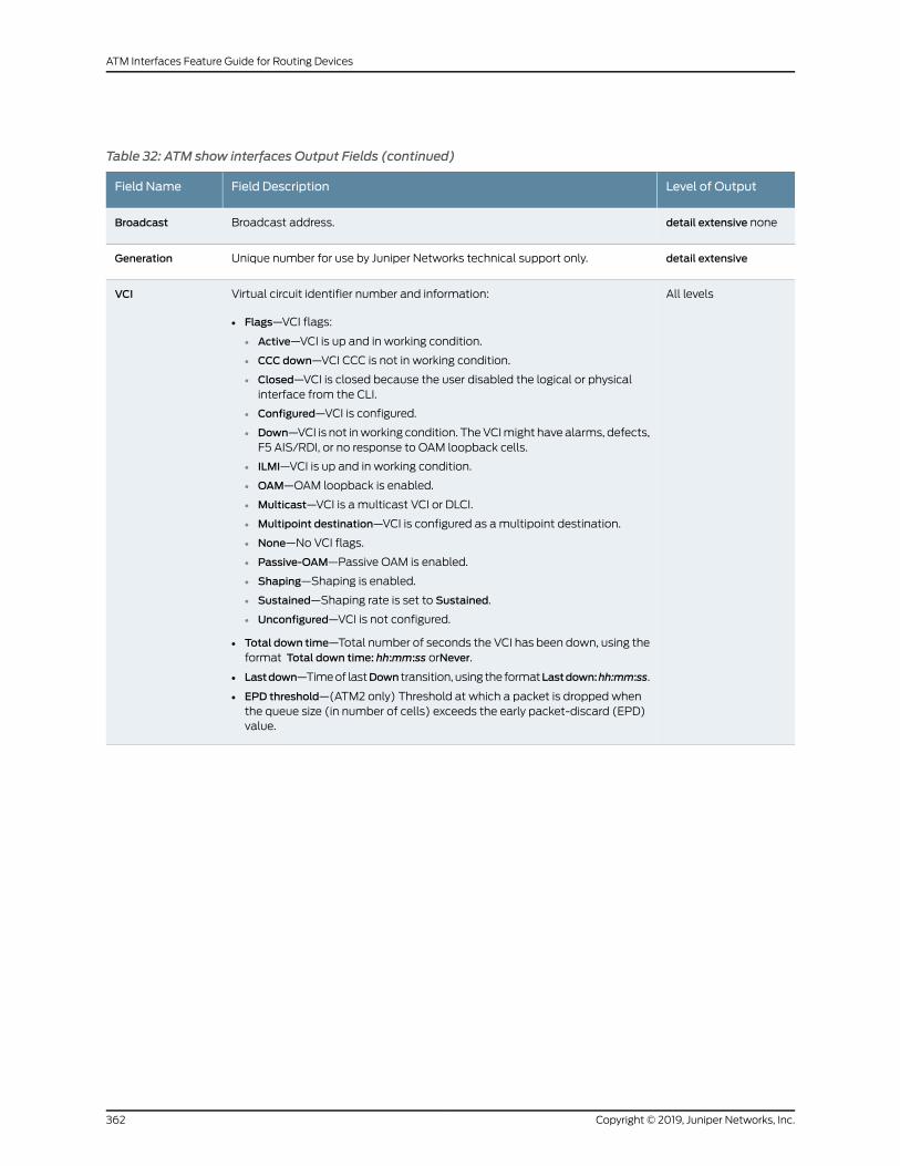
Table 32: ATM show interfaces Output Fields (continued)
Level of OutputField DescriptionField Name
detail extensive noneBroadcast address.Broadcast
detail extensiveUnique number for use by Juniper Networks technical support only.Generation
All levelsVirtual circuit identifier number and information:
• Flags—VCI flags:
• Active—VCI is up and in working condition.
• CCC down—VCI CCC is not in working condition.
• Closed—VCI is closed because the user disabled the logical or physicalinterface from the CLI.
• Configured—VCI is configured.
• Down—VCI is not inworking condition. TheVCImight have alarms, defects,F5 AIS/RDI, or no response to OAM loopback cells.
• ILMI—VCI is up and in working condition.
• OAM—OAM loopback is enabled.
• Multicast—VCI is a multicast VCI or DLCI.
• Multipoint destination—VCI is configured as amultipoint destination.
• None—No VCI flags.
• Passive-OAM—Passive OAM is enabled.
• Shaping—Shaping is enabled.
• Sustained—Shaping rate is set to Sustained.
• Unconfigured—VCI is not configured.
• Total down time—Total number of seconds the VCI has been down, using theformat Total down time: hh:mm:ss orNever.
• Lastdown—Timeof lastDown transition, using the formatLastdown:hh:mm:ss.
• EPD threshold—(ATM2 only) Threshold at which a packet is dropped whenthe queue size (in number of cells) exceeds the early packet-discard (EPD)value.
VCI
Copyright © 2019, Juniper Networks, Inc.362
ATM Interfaces Feature Guide for Routing Devices
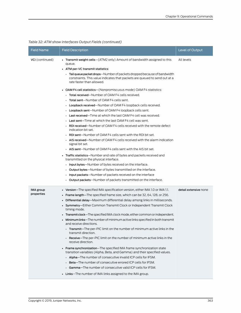
Table 32: ATM show interfaces Output Fields (continued)
Level of OutputField DescriptionField Name
All levels• Transmit weight cells—(ATM2 only) Amount of bandwidth assigned to thisqueue.
• ATMper-VC transmit statistics:
• Tailqueuepacketdrops—Numberofpacketsdroppedbecauseofbandwidthconstraints. This value indicates that packets are queued to send out at arate faster than allowed.
• OAM F4 cell statistics—(Nonpromiscuous mode) OAM F4 statistics:
• Total received—Number of OAM F4 cells received.
• Total sent—Number of OAM F4 cells sent.
• Loopback received—Number of OAM F4 loopback cells received.
• Loopback sent—Number of OAM F4 loopback cells sent.
• Last received—Time at which the last OAM F4 cell was received.
• Last sent—Time at which the last OAM F4 cell was sent.
• RDI received—Number of OAM F4 cells received with the remote defectindication bit set.
• RDI sent—Number of OAM F4 cells sent with the RDI bit set.
• AIS received—Number of OAM F4 cells received with the alarm indicationsignal bit set.
• AIS sent—Number of OAM F4 cells sent with the AIS bit set.
• Traffic statistics—Number and rate of bytes and packets received andtransmitted on the physical interface.
• Input bytes—Number of bytes received on the interface.
• Output bytes—Number of bytes transmitted on the interface.
• Input packets—Number of packets received on the interface
• Output packets—Number of packets transmitted on the interface.
VCI (continued)
detail extensive none• Version—The specified IMA specification version, either IMA 1.0 or IMA 1.1.
• Frame length—The specified frame size, which can be 32, 64, 128, or 256.
• Differential delay—Maximum differential delay among links in milliseconds.
• Symmetry—Either Common Transmit Clock or Independent Transmit Clocktiming mode.
• Transmitclock—Thespecified IMAclockmode,eithercommonor independent.
• Minimumlinks—Thenumberofminimumactive linksspecified inboth transmitand receive directions.
• Transmit—The per-PIC limit on the number of minimum active links in thetransmit direction.
• Receive—The per-PIC limit on the number of minimum active links in thereceive direction.
• Frame synchronization—The specified IMA frame synchronization statetransition variables (Alpha, Beta, and Gamma) and their specified values.
• Alpha—The number of consecutive invalid ICP cells for IFSM.
• Beta—The number of consecutive errored ICP cells for IFSM.
• Gamma—The number of consecutive valid ICP cells for IFSM.
• Links—The number of IMA links assigned to the IMA group.
IMA groupproperties
363Copyright © 2019, Juniper Networks, Inc.
Chapter 9: Operational Commands

Table 32: ATM show interfaces Output Fields (continued)
Level of OutputField DescriptionField Name
detail extensive none• Start-up-FE—Far-end group alarm status
• Config-Aborted—Near-end configuration aborted group alarm status
• Config-Aborted-FE—Far-end configuration aborted group alarm status
• Insufficient-Links—Near-end insufficient links group alarm status
• Insufficient-Links-FE—Far-end insufficient links group alarm status
• Blocked-FE—Far-end blocked group alarm status
• GR-Timing-Mismatch—Group timing mismatch alarm status
IMA group alarms
detail extensive none• Start-up-FE—Far-end group defect status
• Config-Aborted—Near-end configuration aborted group defect status
• Config-Aborted-FE—Far-end configuration aborted group defect status
• Insufficient-Links—Near-end insufficient links group defect status
• Insufficient-Links-FE—Far-end insufficient links group defect status
• Blocked-FE—Far-end blocked group defect status
• GR-Timing-Mismatch—Group timing mismatch defect status
IMA group defects
detail extensive noneNear-end and far-end group statusIMA Group state
detail extensive noneIMA groupmedia status, including seconds, count and state for the followingmedia parameters:
• FC
• FC-FE
• Addr-Mismatch
• Running
• UAS
IMA groupmedia
Sample Output
show interfaces (ATM, IMAGroup)
user@host> show interfaces at-1/0/0
Physical interface: at-1/0/0, Enabled, Physical link is Up IMA group properties: Version : 1.1 Frame length : 128 Differential delay : 25 milliseconds Symmetry : Symmetrical Configuration and Operation Transmit clock : Common Minimum links : Transmit: 1, Receive: 1 Frame synchronization: Alpha: 2, Beta: 2, Gamma: 1 Links : None IMA group alarms : Start-up-FE Config-Aborted Config-Aborted-FE Insufficient-Links Insufficient-Links-FE Blocked-FE GR-Timing-Mismatch IMA group defects : Start-up-FE Config-Aborted Config-Aborted-FE Insufficient-Links Insufficient-Links-FE Blocked-FE GR-Timing-Mismatch IMA Group state: Near end : Start up
Copyright © 2019, Juniper Networks, Inc.364
ATM Interfaces Feature Guide for Routing Devices
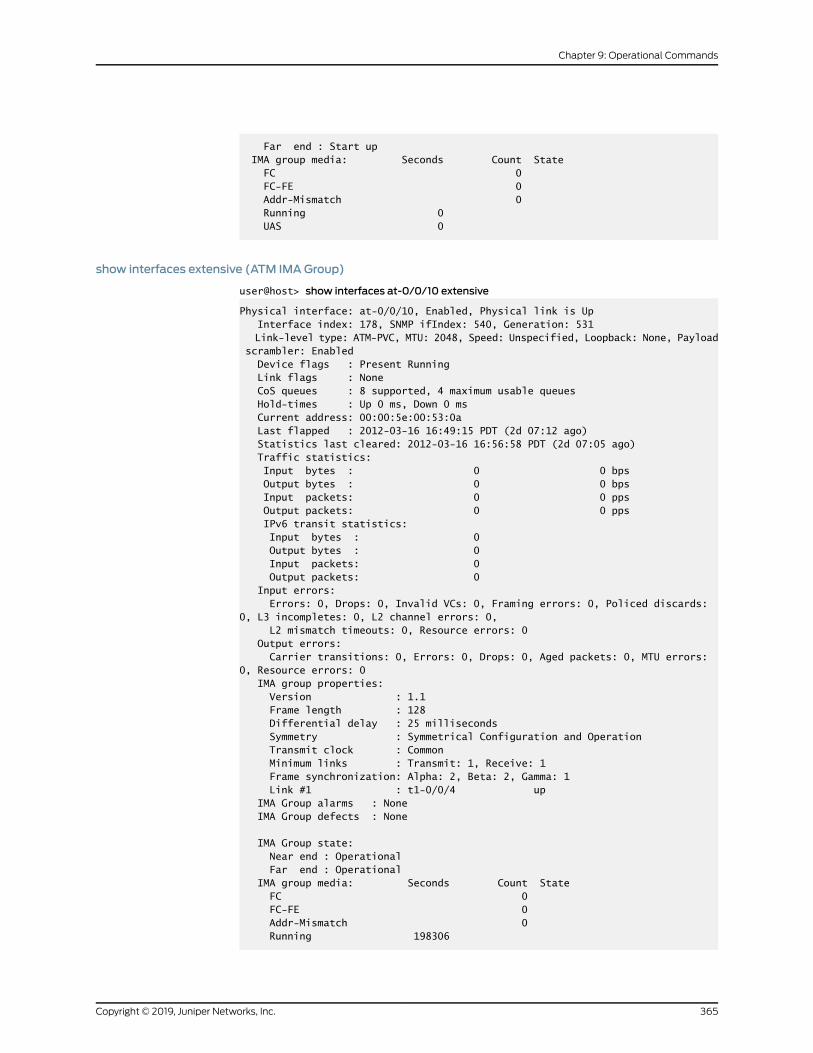
Far end : Start up IMA group media: Seconds Count State FC 0 FC-FE 0 Addr-Mismatch 0 Running 0 UAS 0
show interfaces extensive (ATM IMAGroup)
user@host> show interfaces at-0/0/10 extensive
Physical interface: at-0/0/10, Enabled, Physical link is Up Interface index: 178, SNMP ifIndex: 540, Generation: 531 Link-level type: ATM-PVC, MTU: 2048, Speed: Unspecified, Loopback: None, Payload scrambler: Enabled Device flags : Present Running Link flags : None CoS queues : 8 supported, 4 maximum usable queues Hold-times : Up 0 ms, Down 0 ms Current address: 00:00:5e:00:53:0a Last flapped : 2012-03-16 16:49:15 PDT (2d 07:12 ago) Statistics last cleared: 2012-03-16 16:56:58 PDT (2d 07:05 ago) Traffic statistics: Input bytes : 0 0 bps Output bytes : 0 0 bps Input packets: 0 0 pps Output packets: 0 0 pps IPv6 transit statistics: Input bytes : 0 Output bytes : 0 Input packets: 0 Output packets: 0 Input errors: Errors: 0, Drops: 0, Invalid VCs: 0, Framing errors: 0, Policed discards: 0, L3 incompletes: 0, L2 channel errors: 0, L2 mismatch timeouts: 0, Resource errors: 0 Output errors: Carrier transitions: 0, Errors: 0, Drops: 0, Aged packets: 0, MTU errors: 0, Resource errors: 0 IMA group properties: Version : 1.1 Frame length : 128 Differential delay : 25 milliseconds Symmetry : Symmetrical Configuration and Operation Transmit clock : Common Minimum links : Transmit: 1, Receive: 1 Frame synchronization: Alpha: 2, Beta: 2, Gamma: 1 Link #1 : t1-0/0/4 up IMA Group alarms : None IMA Group defects : None
IMA Group state: Near end : Operational Far end : Operational IMA group media: Seconds Count State FC 0 FC-FE 0 Addr-Mismatch 0 Running 198306
365Copyright © 2019, Juniper Networks, Inc.
Chapter 9: Operational Commands
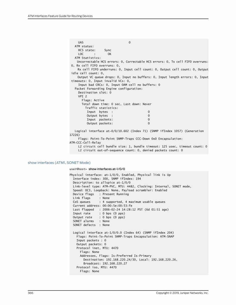
UAS 0 ATM status: HCS state: Sync LOC : OK ATM Statistics: Uncorrectable HCS errors: 0, Correctable HCS errors: 0, Tx cell FIFO overruns: 0, Rx cell FIFO overruns: 0, Rx cell FIFO underruns: 0, Input cell count: 0, Output cell count: 0, Output idle cell count: 0, Output VC queue drops: 0, Input no buffers: 0, Input length errors: 0, Input timeouts: 0, Input invalid VCs: 0, Input bad CRCs: 0, Input OAM cell no buffers: 0 Packet Forwarding Engine configuration: Destination slot: 0 VPI 2 Flags: Active Total down time: 0 sec, Last down: Never Traffic statistics: Input bytes : 0 Output bytes : 0 Input packets: 0 Output packets: 0
Logical interface at-0/0/10.602 (Index 71) (SNMP ifIndex 1057) (Generation 17226) Flags: Point-To-Point SNMP-Traps CCC-Down 0x0 Encapsulation: ATM-CCC-Cell-Relay L2 circuit cell bundle size: 1, bundle timeout: 125 usec, timeout count: 0 L2 circuit out-of-sequence count: 0, denied packets count: 0
show interfaces (ATM1, SONETMode)
user@host> show interfaces at-1/0/0
Physical interface: at-1/0/0, Enabled, Physical link is Up Interface index: 300, SNMP ifIndex: 194 Description: to allspice at-1/0/0 Link-level type: ATM-PVC, MTU: 4482, Clocking: Internal, SONET mode, Speed: OC3, Loopback: None, Payload scrambler: Enabled Device flags : Present Running Link flags : None CoS queues : 4 supported, 4 maximum usable queues Current address: 00:00:5e:00:53:fe Last flapped : 2006-02-24 14:28:12 PST (6d 01:51 ago) Input rate : 0 bps (0 pps) Output rate : 0 bps (0 pps) SONET alarms : None SONET defects : None
Logical interface at-1/0/0.0 (Index 64) (SNMP ifIndex 204) Flags: Point-To-Point SNMP-Traps Encapsulation: ATM-SNAP Input packets : 0 Output packets: 0 Protocol inet, MTU: 4470 Flags: None Addresses, Flags: Is-Preferred Is-Primary Destination: 192.168.220.24/30, Local: 192.168.220.26, Broadcast: 192.168.220.27 Protocol iso, MTU: 4470 Flags: None
Copyright © 2019, Juniper Networks, Inc.366
ATM Interfaces Feature Guide for Routing Devices

VCI 0.128 Flags: Active Total down time: 0 sec, Last down: Never Input packets : 0 Output packets: 0
show interfaces brief (ATM1, SONETMode)
user@host> show interfaces at-1/0/0 brief
Physical interface: at-1/0/0, Enabled, Physical link is Up Description: to allspice at-1/0/0 Link-level type: ATM-PVC, MTU: 4482, Clocking: Internal, SONET mode, Speed: OC3, Loopback: None, Payload scrambler: Enabled Device flags : Present Running Link flags : None
Logical interface at-1/0/0.0 Flags: Point-To-Point SNMP-Traps Encapsulation: ATM-SNAP inet 192.168.220.26/30 iso VCI 0.128 Flags: Active Total down time: 0 sec, Last down: Never
show interfaces detail (ATM1, SONETMode)
user@host> show interfaces at-1/0/0 detail
Physical interface: at-1/0/0, Enabled, Physical link is Up Interface index: 300, SNMP ifIndex: 194, Generation: 183 Description: to allspice at-1/0/0 Link-level type: ATM-PVC, MTU: 4482, Clocking: Internal, SONET mode, Speed: OC3, Loopback: None, Payload scrambler: Enabled Device flags : Present Running Link flags : None CoS queues : 4 supported, 4 maximum usable queues Hold-times : Up 0 ms, Down 0 ms Current address: 00:00:5e:00:53:fe Last flapped : 2006-02-24 14:28:12 PST (6d 01:55 ago) Statistics last cleared: Never Traffic statistics: Input bytes : 0 0 bps Output bytes : 0 0 bps Input packets: 0 0 pps Output packets: 0 0 pps Egress queues: 4 supported, 4 in use Queue counters: Queued packets Transmitted packets Dropped packets
0 best-effort 0 0 0
1 expedited-fo 0 0 0
2 assured-forw 0 0 0
3 network-cont 0 0 0
SONET alarms : None SONET defects : None
367Copyright © 2019, Juniper Networks, Inc.
Chapter 9: Operational Commands

Logical interface at-1/0/0.0 (Index 64) (SNMP ifIndex 204) (Generation 5) Flags: Point-To-Point SNMP-Traps Encapsulation: ATM-SNAP Traffic statistics: Input bytes : 0 Output bytes : 0 Input packets: 0 Output packets: 0 Local statistics: Input bytes : 0 Output bytes : 0 Input packets: 0 Output packets: 0 Transit statistics: Input bytes : 0 0 bps Output bytes : 0 0 bps Input packets: 0 0 pps Output packets: 0 0 pps Protocol inet, MTU: 4470, Generation: 13, Route table: 0 Flags: None Addresses, Flags: Is-Preferred Is-Primary Destination: 192.168.220.24/30, Local: 192.168.220.26, Broadcast: 192.168.220.27, Generation: 14 Protocol iso, MTU: 4470, Generation: 14, Route table: 0 Flags: None VCI 0.128 Flags: Active Total down time: 0 sec, Last down: Never ATM per-VC transmit statistics: Tail queue packet drops: 0 Traffic statistics: Input bytes : 0 Output bytes : 0 Input packets: 0 Output packets: 0
show interfaces extensive (ATM1, SONETMode)
user@host> show interfaces at-1/0/0 extensive
Physical interface: at-1/0/0, Enabled, Physical link is Up Interface index: 300, SNMP ifIndex: 194, Generation: 183 Description: to allspice at-1/0/0 Link-level type: ATM-PVC, MTU: 4482, Clocking: Internal, SONET mode, Speed: OC3, Loopback: None, Payload scrambler: Enabled Device flags : Present Running Link flags : None CoS queues : 4 supported, 4 maximum usable queues Hold-times : Up 0 ms, Down 0 ms Current address: 00:00:5e:00:53:fe Last flapped : 2006-02-24 14:28:12 PST (6d 01:56 ago) Statistics last cleared: Never Traffic statistics: Input bytes : 0 0 bps Output bytes : 0 0 bps Input packets: 0 0 pps Output packets: 0 0 pps Input errors: Errors: 0, Drops: 0, Invalid VCs: 0, Framing errors: 0, Policed discards: 0,
Copyright © 2019, Juniper Networks, Inc.368
ATM Interfaces Feature Guide for Routing Devices

L3 incompletes: 0, L2 channel errors: 0, L2 mismatch timeouts: 0, Resource errors: 0 Output errors: Carrier transitions: 1, Errors: 0, Drops: 0, Aged packets: 0, MTU errors: 0,
Resource errors: 0 Egress queues: 4 supported, 4 in use Queue counters: Queued packets Transmitted packets Dropped packets
0 best-effort 0 0 0
1 expedited-fo 0 0 0
2 assured-forw 0 0 0
3 network-cont 0 0 0
SONET alarms : None SONET defects : None SONET PHY: Seconds Count State PLL Lock 0 0 OK PHY Light 0 0 OK SONET section: BIP-B1 0 0 SEF 0 0 OK LOS 0 0 OK LOF 0 0 OK ES-S 0 SES-S 0 SEFS-S 0 SONET line: BIP-B2 0 0 REI-L 0 0 RDI-L 0 0 OK AIS-L 0 0 OK BERR-SF 0 0 OK BERR-SD 0 0 OK ES-L 0 SES-L 0 UAS-L 0 ES-LFE 0 SES-LFE 0 UAS-LFE 0 SONET path: BIP-B3 0 0 REI-P 0 0 LOP-P 0 0 OK AIS-P 0 0 OK RDI-P 0 0 OK UNEQ-P 1 1 OK PLM-P 0 0 OK ES-P 1 SES-P 1 UAS-P 0 ES-PFE 0 SES-PFE 0 UAS-PFE 0 Received SONET overhead: F1 : 0x00, J0 : 0x00, K1 : 0x00, K2 : 0x00 S1 : 0x00, C2 : 0x13, C2(cmp) : 0x13, F2 : 0x00
369Copyright © 2019, Juniper Networks, Inc.
Chapter 9: Operational Commands

Z3 : 0x00, Z4 : 0x00, S1(cmp) : 0x00 Transmitted SONET overhead: F1 : 0x00, J0 : 0x01, K1 : 0x00, K2 : 0x00 S1 : 0x00, C2 : 0x13, F2 : 0x00, Z3 : 0x00 Z4 : 0x00 ATM status: HCS state: Sync LOC : OK ATM Statistics: Uncorrectable HCS errors: 0, Correctable HCS errors: 0, Tx cell FIFO overruns: 0, Rx cell FIFO overruns: 0, Rx cell FIFO underruns: 0, Input cell count: 0, Output cell count: 0, Output idle cell count: 0, Output VC queue drops: 0, Input no buffers: 0, Input length errors: 0, Input timeouts: 0, Input invalid VCs: 0, Input bad CRCs: 0, Input OAM cell no buffers: 0 Packet Forwarding Engine configuration: Destination slot: 1 CoS information: CoS transmit queue Bandwidth Buffer Priority Limit % bps % usec 0 best-effort 95 147744000 95 0 low none 3 network-control 5 7776000 5 0 low none
Logical interface at-1/0/0.0 (Index 64) (SNMP ifIndex 204) (Generation 5) Flags: Point-To-Point SNMP-Traps Encapsulation: ATM-SNAP Traffic statistics: Input bytes : 0 Output bytes : 0 Input packets: 0 Output packets: 0 Local statistics: Input bytes : 0 Output bytes : 0 Input packets: 0 Output packets: 0 Transit statistics: Input bytes : 0 0 bps Output bytes : 0 0 bps Input packets: 0 0 pps Output packets: 0 0 pps Protocol inet, MTU: 4470, Generation: 13, Route table: 0 Flags: None Addresses, Flags: Is-Preferred Is-Primary Destination: 192.168.220.24/30, Local: 192.168.220.26, Broadcast: 192.168.220.27, Generation: 14 Protocol iso, MTU: 4470, Generation: 14, Route table: 0 Flags: None VCI 0.128 Flags: Active Total down time: 0 sec, Last down: Never ATM per-VC transmit statistics: Tail queue packet drops: 0 Traffic statistics: Input bytes : 0 Output bytes : 0 Input packets: 0 Output packets: 0
Copyright © 2019, Juniper Networks, Inc.370
ATM Interfaces Feature Guide for Routing Devices

show interfaces (ATM2, SDHMode)
user@host> show interfaces at-0/2/1
Physical interface: at-0/2/1, Enabled, Physical link is Up Interface index: 154, SNMP ifIndex: 42 Link-level type: ATM-PVC, MTU: 4482, Clocking: Internal, SDH mode, Speed: OC3,
Loopback: None, Payload scrambler: Enabled Device flags : Present Running Link flags : None CoS queues : 4 supported, 4 maximum usable queues Current address: 00:00:5e:00:53:3f Last flapped : 2006-03-24 13:29:58 PST (00:04:48 ago) Input rate : 0 bps (0 pps) Output rate : 0 bps (0 pps) SDH alarms : None SDH defects : None VPI 0 Flags: Active Total down time: 0 sec, Last down: Never Traffic statistics: Input packets: 0 Output packets: 0
Logical interface at-0/2/1.0 (Index 75) (SNMP ifIndex 51) Flags: Point-To-Point SNMP-Traps 0x4000 Encapsulation: ATM-SNAP Input packets : 0 Output packets: 0 Protocol inet, MTU: 4470 Flags: None Addresses, Flags: Is-Preferred Is-Primary Destination: 10.0.12.6, Local: 10.0.12.5 Protocol iso, MTU: 4470 Flags: None VCI 0.128 Flags: Active Total down time: 0 sec, Last down: Never EPD threshold: 2129, Transmit weight cells: 0 Input packets : 0 Output packets: 0
Logical interface at-0/2/1.32767 (Index 76) (SNMP ifIndex 50) Flags: Point-To-Multipoint No-Multicast SNMP-Traps 0x4000 Encapsulation: ATM-VCMUX Input packets : 0 Output packets: 0 VCI 0.4 Flags: Active Total down time: 0 sec, Last down: Never EPD threshold: 0, Transmit weight cells: 0 Input packets : 0 Output packets: 0
show interfaces brief (ATM2, SDHMode)
user@host> show interfaces at-0/2/1 brief
Physical interface: at-0/2/1, Enabled, Physical link is Up Link-level type: ATM-PVC, MTU: 4482, Clocking: Internal, SDH mode,
371Copyright © 2019, Juniper Networks, Inc.
Chapter 9: Operational Commands

Speed: OC3, Loopback: None, Payload scrambler: Enabled Device flags : Present Running Link flags : None Logical interface at-0/2/1.0 Flags: Point-To-Point SNMP-Traps 0x4000 Encapsulation: ATM-SNAP inet 10.0.12.5 --> 10.0.12.6 iso VCI 0.128 Flags: Active Total down time: 0 sec, Last down: Never EPD threshold: 2129, Transmit weight cells: 0
Logical interface at-0/2/1.32767 Flags: Point-To-Multipoint No-Multicast SNMP-Traps 0x4000 Encapsulation: ATM-VCMUX VCI 0.4 Flags: Active Total down time: 0 sec, Last down: Never EPD threshold: 0, Transmit weight cells: 0
show interfaces detail (ATM2, SDHMode)
user@host> show interfaces at-0/2/1 detail
Physical interface: at-0/2/1, Enabled, Physical link is Up Interface index: 154, SNMP ifIndex: 42, Generation: 40 Link-level type: ATM-PVC, MTU: 4482, Clocking: Internal, SDH mode, Speed: OC3,
Loopback: None, Payload scrambler: Enabled Device flags : Present Running Link flags : None CoS queues : 4 supported, 4 maximum usable queues Hold-times : Up 0 ms, Down 0 ms Current address: 00:00:5e:00:53:3f Last flapped : 2006-03-24 13:29:58 PST (00:05:10 ago) Statistics last cleared: Never Traffic statistics: Input bytes : 0 0 bps Output bytes : 0 0 bps Input packets: 0 0 pps Output packets: 0 0 pps Egress queues: 4 supported, 4 in use Queue counters: Queued packets Transmitted packets Dropped packets
0 best-effort 0 0 0
1 expedited-fo 0 0 0
2 assured-forw 0 0 0
3 network-cont 0 0 0
SDH alarms : None SDH defects : None VPI 0 Flags: Active Total down time: 0 sec, Last down: Never Traffic statistics: Input bytes : 0 Output bytes : 0
Copyright © 2019, Juniper Networks, Inc.372
ATM Interfaces Feature Guide for Routing Devices

Input packets: 0 Output packets: 0
Logical interface at-0/2/1.0 (Index 75) (SNMP ifIndex 51) (Generation 25) Flags: Point-To-Point SNMP-Traps 0x4000 Encapsulation: ATM-SNAP Traffic statistics: Input bytes : 0 Output bytes : 0 Input packets: 0 Output packets: 0 Local statistics: Input bytes : 0 Output bytes : 0 Input packets: 0 Output packets: 0 Transit statistics: Input bytes : 0 0 bps Output bytes : 0 0 bps Input packets: 0 0 pps Output packets: 0 0 pps Protocol inet, MTU: 4470, Generation: 62, Route table: 0 Flags: None Addresses, Flags: Is-Preferred Is-Primary Destination: 10.0.12.6, Local: 10.0.12.5, Broadcast: Unspecified, Generation: 58 Protocol iso, MTU: 4470, Generation: 63, Route table: 0 Flags: None VCI 0.128 Flags: Active Total down time: 0 sec, Last down: Never EPD threshold: 2129, Transmit weight cells: 0 ATM per-VC transmit statistics: Tail queue packet drops: 0 Traffic statistics: Input bytes : 0 Output bytes : 0 Input packets: 0 Output packets: 0 Logical interface at-0/2/1.32767 (Index 76) (SNMP ifIndex 50) (Generation 26) Flags: Point-To-Multipoint No-Multicast SNMP-Traps 0x4000 Encapsulation: ATM-VCMUX Traffic statistics: Input bytes : 0 Output bytes : 0 Input packets: 0 Output packets: 0 Local statistics: Input bytes : 0 Output bytes : 0 Input packets: 0 Output packets: 0 VCI 0.4 Flags: Active Total down time: 0 sec, Last down: Never EPD threshold: 0, Transmit weight cells: 0 ATM per-VC transmit statistics: Tail queue packet drops: 0 Traffic statistics: Input bytes : 0 Output bytes : 0
373Copyright © 2019, Juniper Networks, Inc.
Chapter 9: Operational Commands
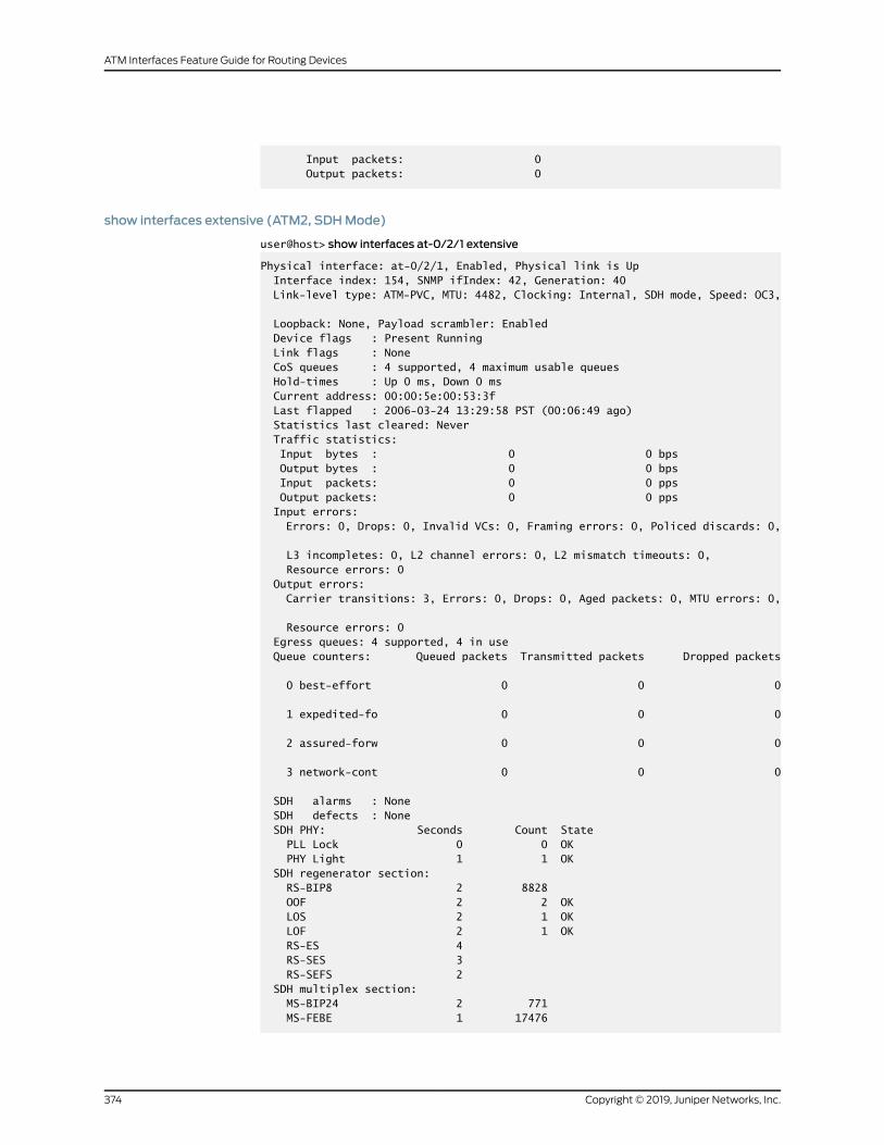
Input packets: 0 Output packets: 0
show interfaces extensive (ATM2, SDHMode)
user@host> show interfaces at-0/2/1 extensive
Physical interface: at-0/2/1, Enabled, Physical link is Up Interface index: 154, SNMP ifIndex: 42, Generation: 40 Link-level type: ATM-PVC, MTU: 4482, Clocking: Internal, SDH mode, Speed: OC3,
Loopback: None, Payload scrambler: Enabled Device flags : Present Running Link flags : None CoS queues : 4 supported, 4 maximum usable queues Hold-times : Up 0 ms, Down 0 ms Current address: 00:00:5e:00:53:3f Last flapped : 2006-03-24 13:29:58 PST (00:06:49 ago) Statistics last cleared: Never Traffic statistics: Input bytes : 0 0 bps Output bytes : 0 0 bps Input packets: 0 0 pps Output packets: 0 0 pps Input errors: Errors: 0, Drops: 0, Invalid VCs: 0, Framing errors: 0, Policed discards: 0,
L3 incompletes: 0, L2 channel errors: 0, L2 mismatch timeouts: 0, Resource errors: 0 Output errors: Carrier transitions: 3, Errors: 0, Drops: 0, Aged packets: 0, MTU errors: 0,
Resource errors: 0 Egress queues: 4 supported, 4 in use Queue counters: Queued packets Transmitted packets Dropped packets
0 best-effort 0 0 0
1 expedited-fo 0 0 0
2 assured-forw 0 0 0
3 network-cont 0 0 0
SDH alarms : None SDH defects : None SDH PHY: Seconds Count State PLL Lock 0 0 OK PHY Light 1 1 OK SDH regenerator section: RS-BIP8 2 8828 OOF 2 2 OK LOS 2 1 OK LOF 2 1 OK RS-ES 4 RS-SES 3 RS-SEFS 2 SDH multiplex section: MS-BIP24 2 771 MS-FEBE 1 17476
Copyright © 2019, Juniper Networks, Inc.374
ATM Interfaces Feature Guide for Routing Devices

MS-FERF 2 1 OK MS-AIS 2 1 OK BERR-SF 0 0 OK BERR-SD 0 0 OK MS-ES 4 MS-SES 2 MS-UAS 0 MS-ES-FE 3 MS-SES-FE 2 MS-UAS-FE 0 SDH path: HP-BIP8 1 6 HP-FEBE 1 251 HP-LOP 0 0 OK HP-AIS 2 1 OK HP-FERF 3 2 OK HP-UNEQ 1 1 OK HP-PLM 2 1 OK HP-ES 4 HP-SES 3 HP-UAS 0 HP-ES-FE 3 HP-SES-FE 3 HP-UAS-FE 0 Received SDH overhead: F1 : 0x00, J0 : 0x00, K1 : 0x00, K2 : 0x00 S1 : 0x00, C2 : 0x13, C2(cmp) : 0x13, F2 : 0x00 Z3 : 0x00, Z4 : 0x00, S1(cmp) : 0x00 Transmitted SDH overhead: F1 : 0x00, J0 : 0x01, K1 : 0x00, K2 : 0x00 S1 : 0x00, C2 : 0x13, F2 : 0x00, Z3 : 0x00 Z4 : 0x00 ATM status: HCS state: Sync LOC : OK ATM Statistics: Uncorrectable HCS errors: 0, Correctable HCS errors: 0, Tx cell FIFO overruns: 0, Rx cell FIFO overruns: 0, Rx cell FIFO underruns: 0, Input cell count: 0, Output cell count: 0, Output idle cell count: 0, Output VC queue drops: 0, Input no buffers: 0, Input length errors: 0, Input timeouts: 0, Input invalid VCs: 0, Input bad CRCs: 0, Input OAM cell no buffers: 0 Packet Forwarding Engine configuration: Destination slot: 0 VPI 0 Flags: Active Total down time: 0 sec, Last down: Never Traffic statistics: Input bytes : 0 Output bytes : 0 Input packets: 0 Output packets: 0
Logical interface at-0/2/1.0 (Index 75) (SNMP ifIndex 51) (Generation 25) Flags: Point-To-Point SNMP-Traps 0x4000 Encapsulation: ATM-SNAP Traffic statistics: Input bytes : 0 Output bytes : 0 Input packets: 0 Output packets: 0
375Copyright © 2019, Juniper Networks, Inc.
Chapter 9: Operational Commands

Local statistics: Input bytes : 0 Output bytes : 0 Input packets: 0 Output packets: 0 Transit statistics: Input bytes : 0 0 bps Output bytes : 0 0 bps Input packets: 0 0 pps Output packets: 0 0 pps Protocol inet, MTU: 4470, Generation: 62, Route table: 0 Flags: None Addresses, Flags: Is-Preferred Is-Primary Destination: 10.0.12.6, Local: 10.0.12.5, Broadcast: Unspecified, Generation: 58 Protocol iso, MTU: 4470, Generation: 63, Route table: 0 Flags: None VCI 0.128 Flags: Active Total down time: 0 sec, Last down: Never EPD threshold: 2129, Transmit weight cells: 0 ATM per-VC transmit statistics: Tail queue packet drops: 0 Traffic statistics: Input bytes : 0 Output bytes : 0 Input packets: 0 Output packets: 0 Logical interface at-0/2/1.32767 (Index 76) (SNMP ifIndex 50) (Generation 26) Flags: Point-To-Multipoint No-Multicast SNMP-Traps 0x4000 Encapsulation: ATM-VCMUX Traffic statistics: Input bytes : 0 Output bytes : 0 Input packets: 0 Output packets: 0 Local statistics: Input bytes : 0 Output bytes : 0 Input packets: 0 Output packets: 0 VCI 0.4 Flags: Active Total down time: 0 sec, Last down: Never EPD threshold: 0, Transmit weight cells: 0 ATM per-VC transmit statistics: Tail queue packet drops: 0 Traffic statistics: Input bytes : 0 Output bytes : 0 Input packets: 0 Output packets: 0
show interfaces (ATM2, SONETMode)
user@host> show interfaces at-0/3/1
Physical interface: at-0/3/1, Enabled, Physical link is Up Interface index: 139, SNMP ifIndex: 67 Link-level type: ATM-PVC, MTU: 4482, Clocking: Internal, SONET mode,
Copyright © 2019, Juniper Networks, Inc.376
ATM Interfaces Feature Guide for Routing Devices

Speed: OC3, Loopback: None, Payload scrambler: Enabled Device flags : Present Running Link flags : None CoS queues : 4 supported, 4 maximum usable queues Current address: 00:00:5e:00:53:5e Last flapped : 2006-03-13 17:46:36 PST (16:01:12 ago) Input rate : 0 bps (0 pps) Output rate : 0 bps (0 pps) SONET alarms : None SONET defects : None VPI 0 Flags: Active, OAM, Shaping CBR, Peak: 50kbps OAM, Period 30 sec, Up count: 10, Down count: 10 Total down time: 0 sec, Last down: Never OAM F4 cell statistics: Total received: 4, Total sent: 4 Loopback received: 4, Loopback sent: 4 RDI received: 0, RDI sent: 0 AIS received: 0 Traffic statistics: Input packets: 4 Output packets: 30 VPI 10 Flags: Active Total down time: 0 sec, Last down: Never Traffic statistics: Input packets: 0 Output packets: 0 Logical interface at-0/3/1.0 (Index 78) (SNMP ifIndex 77) Flags: Point-To-Point Copy-PLP-To-CLP SNMP-Traps 0x4000 Encapsulation: ATM-SNAP Input packets : 0 Output packets: 0 Protocol inet, MTU: 4470 Flags: None Addresses, Flags: Is-Preferred Is-Primary Destination: 10.0.59.5, Local: 10.0.59.6 Protocol iso, MTU: 4470 Flags: None VCI 0.128 Flags: Active Total down time: 0 sec, Last down: Never EPD threshold: 2129, Transmit weight cells: 10 Input packets : 0 Output packets: 0
Logical interface at-0/3/1.32767 (Index 79) (SNMP ifIndex 76) Flags: Point-To-Multipoint Copy-PLP-To-CLP No-Multicast SNMP-Traps 0x4000 Encapsulation: ATM-VCMUX Input packets : 4 Output packets: 30 VCI 0.16 Flags: Active, ILMI Total down time: 0 sec, Last down: Never EPD threshold: 0, Transmit weight cells: 0 Input packets : 0 Output packets: 26 VCI 0.4 Flags: Active, OAM
377Copyright © 2019, Juniper Networks, Inc.
Chapter 9: Operational Commands

OAM, Period 30 sec, Up count: 10, Down count: 10 Total down time: 0 sec, Last down: Never EPD threshold: 2129, Transmit weight cells: 0 Input packets : 4 Output packets: 4 OAM F4 cell statistics: Total received: 4, Total sent: 4 Loopback received: 4, Loopback sent: 4 RDI received: 0, RDI sent: 0 AIS received: 0, AIS sent: 0
show interfaces brief (ATM2, SONETMode)
user@host> show interfaces at-0/3/1 brief
Physical interface: at-0/3/1, Enabled, Physical link is Up Link-level type: ATM-PVC, MTU: 4482, Clocking: Internal, SONET mode, Speed: OC3, Loopback: None, Payload scrambler: Enabled Device flags : Present Running Link flags : None
Logical interface at-0/3/1.0 Flags: Point-To-Point Copy-PLP-To-CLP SNMP-Traps 0x4000 Encapsulation: ATM-SNAP inet 10.0.59.6 --> 10.0.59.5 iso VCI 0.128 Flags: Active Total down time: 0 sec, Last down: Never EPD threshold: 2129, Transmit weight cells: 10
Logical interface at-0/3/1.32767 Flags: Point-To-Multipoint Copy-PLP-To-CLP No-Multicast SNMP-Traps 0x4000 Encapsulation: ATM-VCMUX VCI 0.16 Flags: Active, ILMI Total down time: 0 sec, Last down: Never EPD threshold: 0, Transmit weight cells: 0 VCI 0.4 Flags: Active, OAM Total down time: 0 sec, Last down: Never EPD threshold: 2129, Transmit weight cells: 0
show interfaces detail (ATM2, SONETMode)
user@host> show interfaces at-0/3/1 detail
Physical interface: at-0/3/1, Enabled, Physical link is Up Interface index: 139, SNMP ifIndex: 67, Generation: 22 Link-level type: ATM-PVC, MTU: 4482, Clocking: Internal, SONET mode, Speed: OC3, Loopback: None, Payload scrambler: Enabled Device flags : Present Running Link flags : None CoS queues : 4 supported, 4 maximum usable queues Hold-times : Up 0 ms, Down 0 ms Current address: 00:00:5e:00:53:5e Last flapped : 2006-03-13 17:46:36 PST (16:02:39 ago) Statistics last cleared: Never Traffic statistics:
Copyright © 2019, Juniper Networks, Inc.378
ATM Interfaces Feature Guide for Routing Devices

Input bytes : 312 0 bps Output bytes : 2952 0 bps Input packets: 6 0 pps Output packets: 50 0 pps Egress queues: 4 supported, 4 in use Queue counters: Queued packets Transmitted packets Dropped packets
0 best-effort 44 44 0
1 expedited-fo 0 0 0
2 assured-forw 0 0 0
3 network-cont 6 6 0
SONET alarms : None SONET defects : None VPI 0 Flags: Active, OAM, Shaping CBR, Peak: 50kbps OAM, Period 30 sec, Up count: 10, Down count: 10 Total down time: 0 sec, Last down: Never OAM F4 cell statistics: Total received: 6, Total sent: 6 Loopback received: 6, Loopback sent: 6 Last received: 00:00:29, Last sent: 00:00:29 RDI received: 0, RDI sent: 0 AIS received: 0 Traffic statistics: Input bytes : 312 Output bytes : 2952 Input packets: 6 Output packets: 50 VPI 10 Flags: Active Total down time: 0 sec, Last down: Never Traffic statistics: Input bytes : 0 Output bytes : 0 Input packets: 0 Output packets: 0
Logical interface at-0/3/1.0 (Index 78) (SNMP ifIndex 77) (Generation 20) Flags: Point-To-Point Copy-PLP-To-CLP SNMP-Traps 0x4000 Encapsulation: ATM-SNAP Traffic statistics: Input bytes : 0 Output bytes : 0 Input packets: 0 Output packets: 0 Local statistics: Input bytes : 0 Output bytes : 0 Input packets: 0 Output packets: 0 Transit statistics: Input bytes : 0 0 bps Output bytes : 0 0 bps Input packets: 0 0 pps Output packets: 0 0 pps
379Copyright © 2019, Juniper Networks, Inc.
Chapter 9: Operational Commands
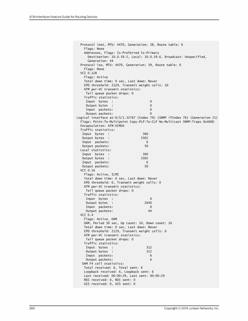
Protocol inet, MTU: 4470, Generation: 38, Route table: 0 Flags: None Addresses, Flags: Is-Preferred Is-Primary Destination: 10.0.59.5, Local: 10.0.59.6, Broadcast: Unspecified, Generation: 44 Protocol iso, MTU: 4470, Generation: 39, Route table: 0 Flags: None VCI 0.128 Flags: Active Total down time: 0 sec, Last down: Never EPD threshold: 2129, Transmit weight cells: 10 ATM per-VC transmit statistics: Tail queue packet drops: 0 Traffic statistics: Input bytes : 0 Output bytes : 0 Input packets: 0 Output packets: 0 Logical interface at-0/3/1.32767 (Index 79) (SNMP ifIndex 76) (Generation 21) Flags: Point-To-Multipoint Copy-PLP-To-CLP No-Multicast SNMP-Traps 0x4000 Encapsulation: ATM-VCMUX Traffic statistics: Input bytes : 360 Output bytes : 3302 Input packets: 6 Output packets: 50 Local statistics: Input bytes : 360 Output bytes : 3302 Input packets: 6 Output packets: 50 VCI 0.16 Flags: Active, ILMI Total down time: 0 sec, Last down: Never EPD threshold: 0, Transmit weight cells: 0 ATM per-VC transmit statistics: Tail queue packet drops: 0 Traffic statistics: Input bytes : 0 Output bytes : 2640 Input packets: 0 Output packets: 44 VCI 0.4 Flags: Active, OAM OAM, Period 30 sec, Up count: 10, Down count: 10 Total down time: 0 sec, Last down: Never EPD threshold: 2129, Transmit weight cells: 0 ATM per-VC transmit statistics: Tail queue packet drops: 0 Traffic statistics: Input bytes : 312 Output bytes : 312 Input packets: 6 Output packets: 6 OAM F4 cell statistics: Total received: 6, Total sent: 6 Loopback received: 6, Loopback sent: 6 Last received: 00:00:29, Last sent: 00:00:29 RDI received: 0, RDI sent: 0 AIS received: 0, AIS sent: 0
Copyright © 2019, Juniper Networks, Inc.380
ATM Interfaces Feature Guide for Routing Devices
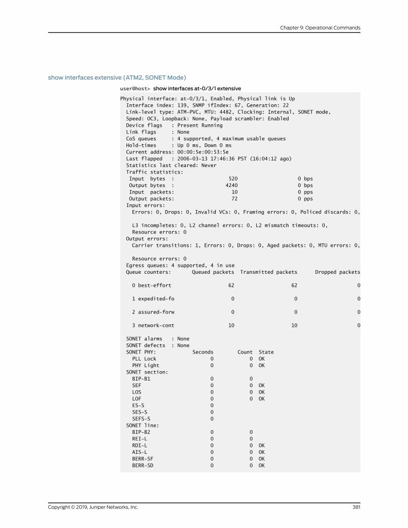
show interfaces extensive (ATM2, SONETMode)
user@host> show interfaces at-0/3/1 extensive
Physical interface: at-0/3/1, Enabled, Physical link is Up Interface index: 139, SNMP ifIndex: 67, Generation: 22 Link-level type: ATM-PVC, MTU: 4482, Clocking: Internal, SONET mode, Speed: OC3, Loopback: None, Payload scrambler: Enabled Device flags : Present Running Link flags : None CoS queues : 4 supported, 4 maximum usable queues Hold-times : Up 0 ms, Down 0 ms Current address: 00:00:5e:00:53:5e Last flapped : 2006-03-13 17:46:36 PST (16:04:12 ago) Statistics last cleared: Never Traffic statistics: Input bytes : 520 0 bps Output bytes : 4240 0 bps Input packets: 10 0 pps Output packets: 72 0 pps Input errors: Errors: 0, Drops: 0, Invalid VCs: 0, Framing errors: 0, Policed discards: 0,
L3 incompletes: 0, L2 channel errors: 0, L2 mismatch timeouts: 0, Resource errors: 0 Output errors: Carrier transitions: 1, Errors: 0, Drops: 0, Aged packets: 0, MTU errors: 0,
Resource errors: 0 Egress queues: 4 supported, 4 in use Queue counters: Queued packets Transmitted packets Dropped packets
0 best-effort 62 62 0
1 expedited-fo 0 0 0
2 assured-forw 0 0 0
3 network-cont 10 10 0
SONET alarms : None SONET defects : None SONET PHY: Seconds Count State PLL Lock 0 0 OK PHY Light 0 0 OK SONET section: BIP-B1 0 0 SEF 0 0 OK LOS 0 0 OK LOF 0 0 OK ES-S 0 SES-S 0 SEFS-S 0 SONET line: BIP-B2 0 0 REI-L 0 0 RDI-L 0 0 OK AIS-L 0 0 OK BERR-SF 0 0 OK BERR-SD 0 0 OK
381Copyright © 2019, Juniper Networks, Inc.
Chapter 9: Operational Commands
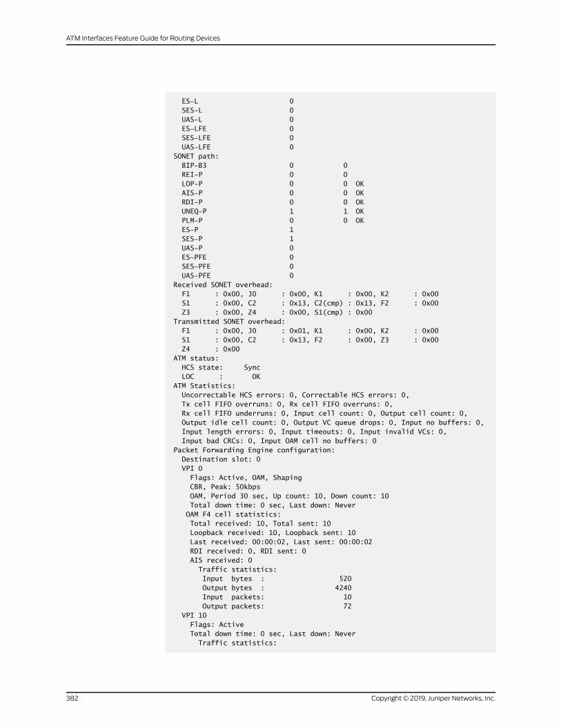
ES-L 0 SES-L 0 UAS-L 0 ES-LFE 0 SES-LFE 0 UAS-LFE 0 SONET path: BIP-B3 0 0 REI-P 0 0 LOP-P 0 0 OK AIS-P 0 0 OK RDI-P 0 0 OK UNEQ-P 1 1 OK PLM-P 0 0 OK ES-P 1 SES-P 1 UAS-P 0 ES-PFE 0 SES-PFE 0 UAS-PFE 0 Received SONET overhead: F1 : 0x00, J0 : 0x00, K1 : 0x00, K2 : 0x00 S1 : 0x00, C2 : 0x13, C2(cmp) : 0x13, F2 : 0x00 Z3 : 0x00, Z4 : 0x00, S1(cmp) : 0x00 Transmitted SONET overhead: F1 : 0x00, J0 : 0x01, K1 : 0x00, K2 : 0x00 S1 : 0x00, C2 : 0x13, F2 : 0x00, Z3 : 0x00 Z4 : 0x00 ATM status: HCS state: Sync LOC : OK ATM Statistics: Uncorrectable HCS errors: 0, Correctable HCS errors: 0, Tx cell FIFO overruns: 0, Rx cell FIFO overruns: 0, Rx cell FIFO underruns: 0, Input cell count: 0, Output cell count: 0, Output idle cell count: 0, Output VC queue drops: 0, Input no buffers: 0, Input length errors: 0, Input timeouts: 0, Input invalid VCs: 0, Input bad CRCs: 0, Input OAM cell no buffers: 0 Packet Forwarding Engine configuration: Destination slot: 0 VPI 0 Flags: Active, OAM, Shaping CBR, Peak: 50kbps OAM, Period 30 sec, Up count: 10, Down count: 10 Total down time: 0 sec, Last down: Never OAM F4 cell statistics: Total received: 10, Total sent: 10 Loopback received: 10, Loopback sent: 10 Last received: 00:00:02, Last sent: 00:00:02 RDI received: 0, RDI sent: 0 AIS received: 0 Traffic statistics: Input bytes : 520 Output bytes : 4240 Input packets: 10 Output packets: 72 VPI 10 Flags: Active Total down time: 0 sec, Last down: Never Traffic statistics:
Copyright © 2019, Juniper Networks, Inc.382
ATM Interfaces Feature Guide for Routing Devices

Input bytes : 0 Output bytes : 0 Input packets: 0 Output packets: 0
Logical interface at-0/3/1.0 (Index 78) (SNMP ifIndex 77) (Generation 20) Flags: Point-To-Point Copy-PLP-To-CLP SNMP-Traps 0x4000 Encapsulation: ATM-SNAP Traffic statistics: Input bytes : 0 Output bytes : 0 Input packets: 0 Output packets: 0 Local statistics: Input bytes : 0 Output bytes : 0 Input packets: 0 Output packets: 0 Transit statistics: Input bytes : 0 0 bps Output bytes : 0 0 bps Input packets: 0 0 pps Output packets: 0 0 pps Protocol inet, MTU: 4470, Generation: 38, Route table: 0 Flags: None Addresses, Flags: Is-Preferred Is-Primary Destination: 10.0.59.5, Local: 10.0.59.6, Broadcast: Unspecified, Generation: 44 Protocol iso, MTU: 4470, Generation: 39, Route table: 0 Flags: None VCI 0.128 Flags: Active Total down time: 0 sec, Last down: Never EPD threshold: 2129, Transmit weight cells: 10 ATM per-VC transmit statistics: Tail queue packet drops: 0 Traffic statistics: Input bytes : 0 Output bytes : 0 Input packets: 0 Output packets: 0
Logical interface at-0/3/1.32767 (Index 79) (SNMP ifIndex 76) (Generation 21) Flags: Point-To-Multipoint Copy-PLP-To-CLP No-Multicast SNMP-Traps 0x4000 Encapsulation: ATM-VCMUX Traffic statistics: Input bytes : 660 Output bytes : 5473 Input packets: 11 Output packets: 83 Local statistics: Input bytes : 660 Output bytes : 5473 Input packets: 11 Output packets: 83 VCI 0.16 Flags: Active, ILMI Total down time: 0 sec, Last down: Never EPD threshold: 0, Transmit weight cells: 0 ATM per-VC transmit statistics:
383Copyright © 2019, Juniper Networks, Inc.
Chapter 9: Operational Commands
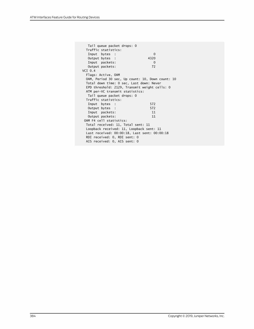
Tail queue packet drops: 0 Traffic statistics: Input bytes : 0 Output bytes : 4320 Input packets: 0 Output packets: 72 VCI 0.4 Flags: Active, OAM OAM, Period 30 sec, Up count: 10, Down count: 10 Total down time: 0 sec, Last down: Never EPD threshold: 2129, Transmit weight cells: 0 ATM per-VC transmit statistics: Tail queue packet drops: 0 Traffic statistics: Input bytes : 572 Output bytes : 572 Input packets: 11 Output packets: 11 OAM F4 cell statistics: Total received: 11, Total sent: 11 Loopback received: 11, Loopback sent: 11 Last received: 00:00:18, Last sent: 00:00:18 RDI received: 0, RDI sent: 0 AIS received: 0, AIS sent: 0
Copyright © 2019, Juniper Networks, Inc.384
ATM Interfaces Feature Guide for Routing Devices


