
Étude cinématique du châssis d’un véhicule de compétition ...

DESIGN AND ANALYSIS OF CAM MECHANISM WITH NEGATIVE RADIUSROLLER-FOLLOWER
Jung-Fa HsiehDepartment of Mechanical Engineering, Far East University, Tainan, Taiwan
E-mail: [email protected]
Received July 2015, Accepted October 2015No. 15-CSME-80, E.I.C. Accession 3855
ABSTRACTThis paper presents a simple method for the design and analysis of a cam mechanism with a negative radiusroller-follower. In the proposed approach, conjugate surface theory is employed to derive a kinematic modelof the cam mechanism. Analytical expressions for the pressure angle and principal curvatures of the camprofile are then derived. Finally, analytical expressions for the angular velocity and angular acceleration ofthe roller are derived. The validity of the proposed design methodology is demonstrated by machining acam mechanism having a negative radius roller-follower with a radius of 100 mm.
Keywords: negative radius roller-follower; pressure angle; principal curvature.
CONCEPTION ET ANALYSE D’UN MÉCANISME À CAME AVEC POUSSOIR À GALET DEVALEUR NÉGATIVE
RÉSUMÉCet article présente une méthode simple pour la conception et l’analyse d’un mécanisme à came avec pous-soir à galet de valeur négative. Dans l’approche proposée, la théorie de surface conjuguée est employée pourdériver un modèle cinématique du mécanisme à came. Les expressions analytiques pour l’angle de pressionet des courbures principales du profil de la came sont dérivées par la suite. Finalement, les expressions ana-lytiques pour la vélocité angulaire et l’accélération angulaire du poussoir sont dérivées. La validité de laméthodologie proposée est démontrée en usinant un mécanisme à came comportant un poussoir à galet d’unrayon de 100 mm.
Mots-clés : poussoir à galet d’un rayon de valeur négative; angle de pression; courbure principale.
Transactions of the Canadian Society for Mechanical Engineering, Vol. 40, No. 1, 2016 89

NOMENCLATURE
(xyz)0 configuration of frame (xyz)0 built in Geneva wheel0S curved slot surfacerS roller surface0n unit outward normal of slot surfaceR roller radiusrb base circle radius of camr local curvature radius of camh lift height of followerψ pressure angleθ1 rotation angle of camw1 angular speed of camw2 angular speed of rollerε2 angular acceleration of rollers2 displacement of follower
1. INTRODUCTION
Cam elements have many advantageous features for mechanical transmission systems, including simplicity,reliability, repeatability and a low running noise. Contact pairs comprising a convex cylinder and a concavecylinder have a large contact area, and hence a low contact stress [1]. Thus, cam profiles generally havea convex face, while follower profiles have either a convex face or a flat face. In order to distinguishconventional construct, followers with a concave face are referred to as negative radius followers. Camswith negative radius roller-followers use the inner rings of commercial roller bearings as roller-followers.The use of such mechanisms is particularly valuable in applications where space is at a premium and veryhigh forces are involved. Carra et al. [2] presented a design nomograph and synthesis procedure for findingthe suitable combination of parameters to satisfy the specified motion law without under-cutting. Wu etal. [3] compared the contact stress of two disc cam mechanisms with a concave-faced follower and a flat-faced follower, respectively. The results showed that the cam mechanism with a concave-faced followerproduced a lower maximum contact stress than that with a common flat-faced follower. Moreover, it wasshown that the negative radius roller-follower caused the sliding friction between the cam and the followerto be converted to rolling friction. Lin and Chang [4, 5] proposed the conditions of no-undercutting andcontact-retaining of the disc mechanism with negative radius roller follower. Furthermore, they presentedthe mechanical model of a disc cam mechanism with an offset translating negative radius roller followerand deduced the efficiency expression. Later, the same researchers [6] studied the force-locking and shape-locking conjugate cam mechanisms. They extended the “definite proportion and division point” method tosolve the theoretical and the actual contour of the cams with negative radius translating roller. Hidalgo-Martinez et al. [7] applied Bezier curves for designing cams with a follower of negative radius. Theyproposed a numerical method for optimizing the design of the cam profile using a Bezier ordinate as anoptimization parameter.
However, the literature lacks a systematic investigation into the design and analysis of cam mechanismswith negative radius roller-followers. Accordingly, this study presents a simple yet robust methodologyfor the design and analysis of such mechanisms. The proposed methodology comprises four steps, namely(1) establishing a kinematic model of the cam mechanism, (2) designing the cam profile, (3) analyzingthe pressure angle and principal curvatures of the cam, and (4) deriving the kinematic model of the roller-follower.
90 Transactions of the Canadian Society for Mechanical Engineering, Vol. 40, No. 1, 2016

Fig. 1. Cam mechanism with negative radius follower.
Fig. 2. Simplified representation of cam and follower mechanism for synthesis of cam profile.
2. SURFACE GEOMETRY
In order to analyze the contact stress in a cam mechanism, it is first necessary to determine the profile of thecam. As discussed above, cams with negative radius roller-followers use the inner rings of commercial rollerbearings as followers. In other words, the cam fits within an inner ring, as shown in Fig. 1. In synthesizingthe cam profile, the cam mechanism can be represented using the simplified model shown in Fig. 2. Asshown, the cam rotates with an angular speed w1 in the clockwise direction about its center point, 00. Asthe cam rotates, the follower rises to a total lift height h over a specified rise angle, remains in a high dwellposition over the high dwell angle, falls through a distance h over the return angle, and then remains in alow dwell position over the low dwell angle.
To determine the cam profile using conjugate theory, it is necessary to label all of the coordinate frames inthe system, starting with the cam (marked as “0” in Fig. 2) and ending with the translating follower (markedas “2” in Fig. 1). Note that parameter b2 is defined as b2 = rb + s2(θ1), where rb is the base circle radius ofthe cam and s2 is the translating follower displacement.
Transactions of the Canadian Society for Mechanical Engineering, Vol. 40, No. 1, 2016 91
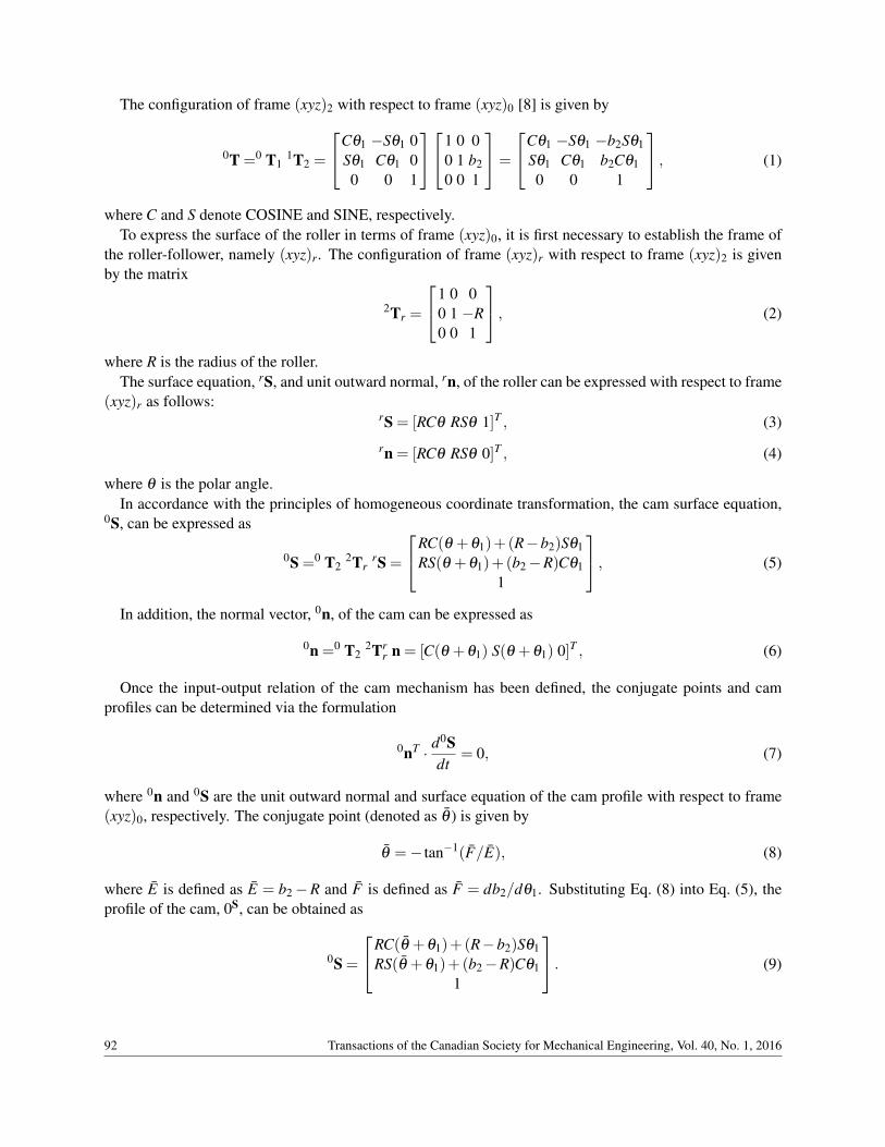
The configuration of frame (xyz)2 with respect to frame (xyz)0 [8] is given by
0T =0 T11T2 =
Cθ1 −Sθ1 0Sθ1 Cθ1 00 0 1
1 0 00 1 b20 0 1
=
Cθ1 −Sθ1 −b2Sθ1Sθ1 Cθ1 b2Cθ10 0 1
, (1)
where C and S denote COSINE and SINE, respectively.To express the surface of the roller in terms of frame (xyz)0, it is first necessary to establish the frame of
the roller-follower, namely (xyz)r. The configuration of frame (xyz)r with respect to frame (xyz)2 is givenby the matrix
2Tr =
1 0 00 1 −R0 0 1
, (2)
where R is the radius of the roller.The surface equation, rS, and unit outward normal, rn, of the roller can be expressed with respect to frame
(xyz)r as follows:rS = [RCθ RSθ 1]T , (3)
rn = [RCθ RSθ 0]T , (4)
where θ is the polar angle.In accordance with the principles of homogeneous coordinate transformation, the cam surface equation,
0S, can be expressed as
0S =0 T22Tr
rS =
RC(θ +θ1)+(R−b2)Sθ1RS(θ +θ1)+(b2−R)Cθ1
1
, (5)
In addition, the normal vector, 0n, of the cam can be expressed as
0n =0 T22Tr
r n = [C(θ +θ1) S(θ +θ1) 0]T , (6)
Once the input-output relation of the cam mechanism has been defined, the conjugate points and camprofiles can be determined via the formulation
0nT · d0Sdt
= 0, (7)
where 0n and 0S are the unit outward normal and surface equation of the cam profile with respect to frame(xyz)0, respectively. The conjugate point (denoted as θ ) is given by
θ =− tan−1(F/E), (8)
where E is defined as E = b2−R and F is defined as F = db2/dθ1. Substituting Eq. (8) into Eq. (5), theprofile of the cam, 0S, can be obtained as
0S =
RC(θ +θ1)+(R−b2)Sθ1RS(θ +θ1)+(b2−R)Cθ1
1
. (9)
92 Transactions of the Canadian Society for Mechanical Engineering, Vol. 40, No. 1, 2016

Fig. 3. Pressure angle of cam mechanism with negative radius follower.
3. PRESSURE ANGLE
As shown in Fig. 3, the pressure angle is defined as the angle between the direction of motion (i.e., velocity)of the follower and the direction of the force transmission axis [9]. The pressure angle at the contact point pbetween the cam and the roller is given by
tanψ =‖1np×1 vp‖|1np ·1 vp|
, (10)
where the unit normal vector of the contact point, 1np, and the direction of velocity of the contact point, 1vp,are both defined with respect to the fixed frame (xyz)1.
The unit normal vector of the contact point on the roller-follower surface with respect to frame (xyz)1 isgiven by
1np =1 T2
2Trnp = [Cθ Sθ 0]T . (11)
Meanwhile, the location of the contact point, with respect to frame (xyz)1 is given by
1Sp =1 T2
2TrrS+ p = [RCθ RSθ −R+b2 1]T . (12)
Since the roller-follower translates along the y1 axis direction, the direction of velocity of the contactpoint on the roller-follower surface with respect to frame (xyz)1 can be expressed as
1vp =d1Sdt
=
[0
db2
dt0]T
. (13)
Substituting Eqs. (11) and (13) into Eq. (10), the pressure angle, ψ , can be derived as
tanψ =
db2dθ1
R−b2=
db2dθ1
R− (rb + s2). (14)
Equation (14) shows that an increase of the base circle radius rb leads to a lower pressure angle ψ . No-tably, a higher maximum velocity causes an undesirable increase of the contact pressure angle. However, fornegative radius (concave-faced) follower cams, the adverse effects of a higher pressure angle are generallyinsignificant.
Transactions of the Canadian Society for Mechanical Engineering, Vol. 40, No. 1, 2016 93
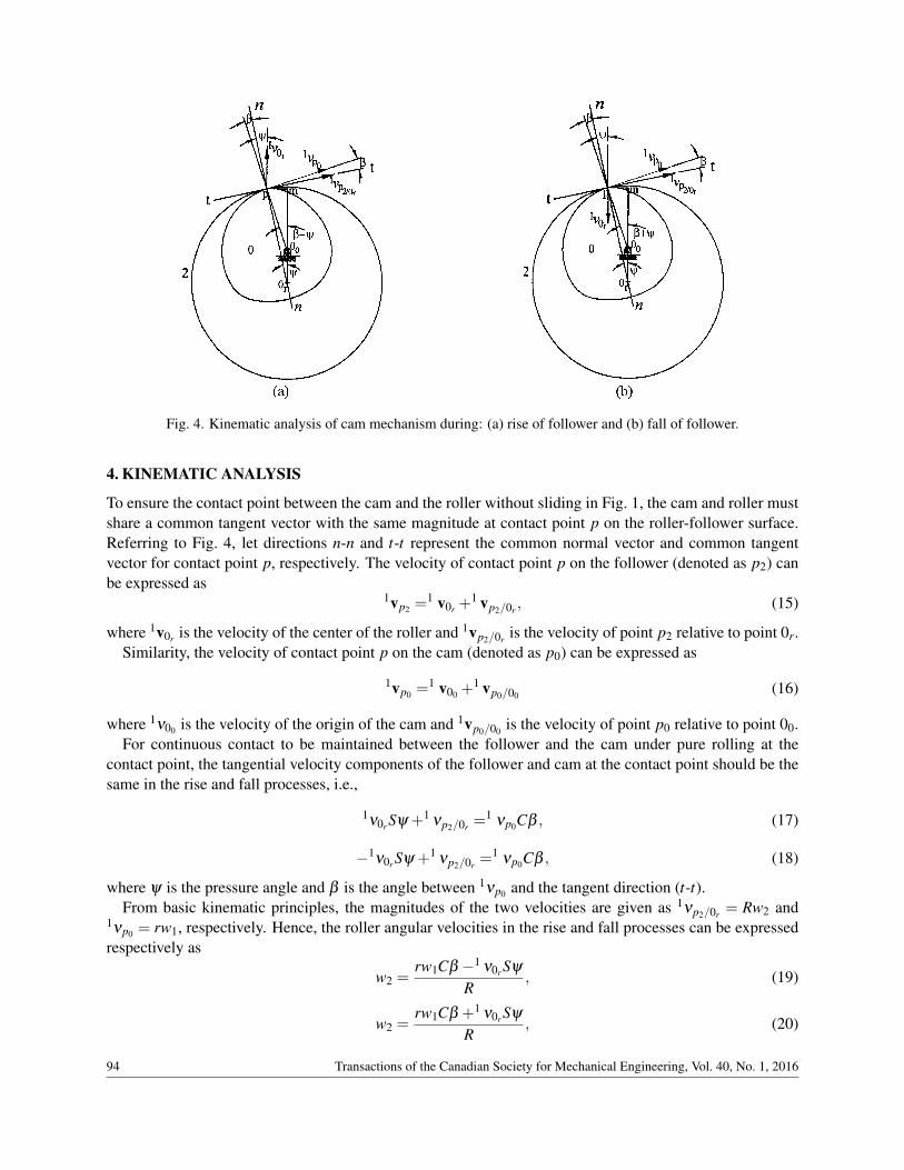
Fig. 4. Kinematic analysis of cam mechanism during: (a) rise of follower and (b) fall of follower.
4. KINEMATIC ANALYSIS
To ensure the contact point between the cam and the roller without sliding in Fig. 1, the cam and roller mustshare a common tangent vector with the same magnitude at contact point p on the roller-follower surface.Referring to Fig. 4, let directions n-n and t-t represent the common normal vector and common tangentvector for contact point p, respectively. The velocity of contact point p on the follower (denoted as p2) canbe expressed as
1vp2 =1 v0r +
1 vp2/0r , (15)
where 1v0r is the velocity of the center of the roller and 1vp2/0r is the velocity of point p2 relative to point 0r.Similarity, the velocity of contact point p on the cam (denoted as p0) can be expressed as
1vp0 =1 v00 +
1 vp0/00 (16)
where 1ν00 is the velocity of the origin of the cam and 1vp0/00 is the velocity of point p0 relative to point 00.For continuous contact to be maintained between the follower and the cam under pure rolling at the
contact point, the tangential velocity components of the follower and cam at the contact point should be thesame in the rise and fall processes, i.e.,
1ν0r Sψ +1
νp2/0r =1
νp0Cβ , (17)
−1ν0r Sψ +1
νp2/0r =1
νp0Cβ , (18)
where ψ is the pressure angle and β is the angle between 1νp0 and the tangent direction (t-t).From basic kinematic principles, the magnitudes of the two velocities are given as 1νp2/0r = Rw2 and
1νp0 = rw1, respectively. Hence, the roller angular velocities in the rise and fall processes can be expressedrespectively as
w2 =rw1Cβ −1 ν0r Sψ
R, (19)
w2 =rw1Cβ +1 ν0r Sψ
R, (20)
94 Transactions of the Canadian Society for Mechanical Engineering, Vol. 40, No. 1, 2016
where r is the local curvature radius of the cam at the contact point and 1ν0r = db2/dθ1w1.Parameter β in Eqs. (19) and (20) can be derived trigonometrically as
β = tan−1[
RSψ
RCψ− (R−b2)
]−ψ (21)
The roller angular accelerations in the rise and fall processes can then be obtained respectively as
ε2 =dw2
dt=
w1Cβdrdt − rw1Sβ
dβ
dt −d2b2dθ 2
1w2
1Sψ− d2b2dθ 2
1w1Cψ
dψ
dt
R, (22)
ε2 =dw2
dt=
w1Cβdrdt − rw1Sβ
dβ
dt +d2b2dθ 2
1w2
1Sψ + d2b2dθ 2
1w1Cψ
dψ
dt
R, (23)
where dr/dt, dβ/dt and dψ/dt are given in Eqs. (A1–A3) in Appendix A.
5. ANALYSIS OF CURVATURE RADIUS
The curvature radius of the cam must be analyzed in order to prevent the occurrence of singular points. Notethat the radius of curvature of the cam cannot be greater than the radius of the follower since unintendedmultiple-point contacts will otherwise occur [10]. According to basic differential geometry principles, theprincipal curvatures of the cam profile can be evaluated as follows:
K1,K2 = H±√
H2−K, (24)
where K1 and K2 are the principal curvatures, and H and K are defined respectively as
K =LN−M2
EG−F2 and H =2FM−EN−GL
2(EG−F2), (25)
where
L = 0n · ∂2 0S
∂u2 , M = 0n · ∂ 2 0S∂u∂θ1
, N = 0n · ∂2 0S
∂θ 21
E =∂ 0S∂u· ∂
0S∂u
, F =∂ 0S∂u· ∂
0S∂θ1
,
and
G =∂ 0S∂θ1· ∂
0S∂θ1
.
(see Eqs. (B1–B6) in Appendix B).The present study considers the case of a planar cam. Hence, one of the principle curvatures is equal to
zero. Moreover, the curvature radius, ρ , of the cam profile is equal to the inverse of the principal curvature
6. IMPLEMENTATION
To validate the design methodology presented in Sections 2–5, a cam mechanism was designed with anegative radius roller-follower having a radius of 100 mm. The motions of the cam and follower weredefined by a modified sine motion curve. The follower motion was specified as follows: 20 mm rise for camrotation from 0 to 150◦, dwell for cam rotation to 180◦, 20 mm fall for cam rotation to 330◦, and dwell for
Transactions of the Canadian Society for Mechanical Engineering, Vol. 40, No. 1, 2016 95
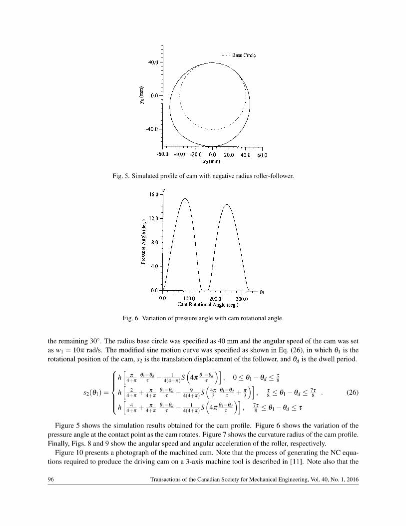
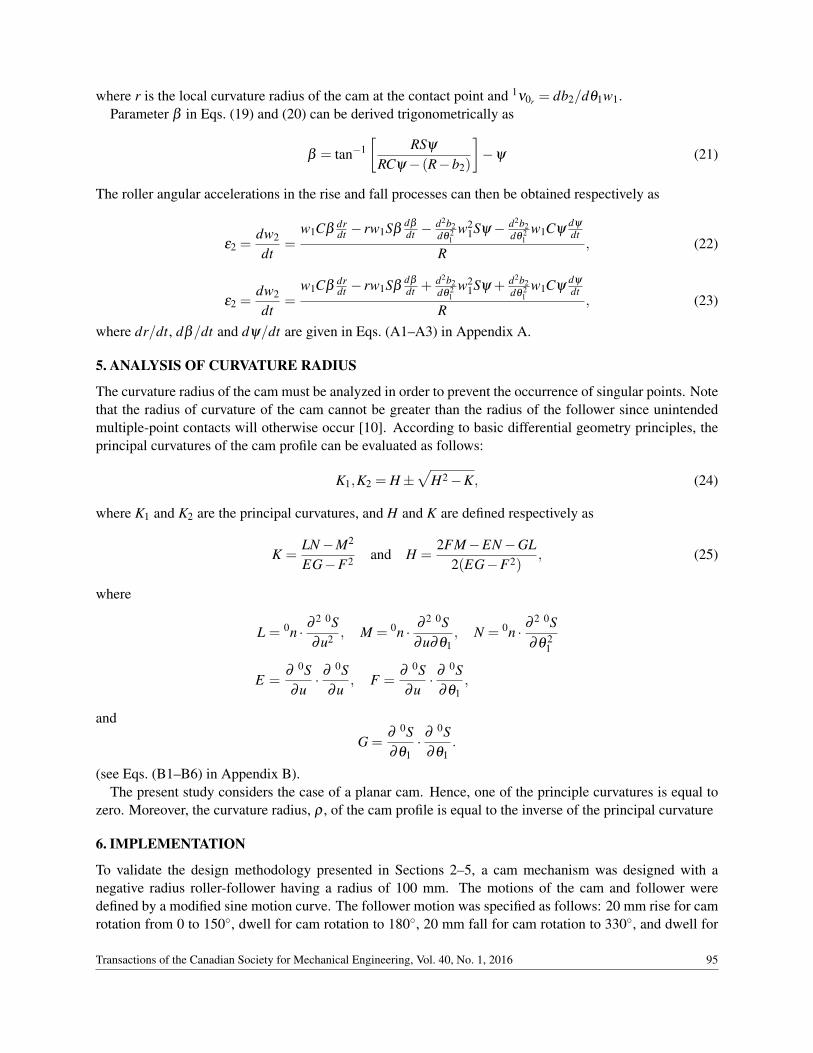
Fig. 5. Simulated profile of cam with negative radius roller-follower.
Fig. 6. Variation of pressure angle with cam rotational angle.
the remaining 30◦. The radius base circle was specified as 40 mm and the angular speed of the cam was setas w1 = 10π rad/s. The modified sine motion curve was specified as shown in Eq. (26), in which θ1 is therotational position of the cam, s2 is the translation displacement of the follower, and θd is the dwell period.
s2(θ1) =
h[
π
4+π
θ1−θdτ− 1
4(4+π)S(
4πθ1−θd
τ
)], 0≤ θ1−θd ≤ τ
8
h[
24+π
+ π
4+π
θ1−θdτ− 9
4(4+π)S(
4π
3θ1−θd
τ+ π
3
)], τ
8 ≤ θ1−θd ≤ 7τ
8
h[
44+π
+ π
4+π
θ1−θdτ− 1
4(4+π)S(
4πθ1−θd
τ
)], 7τ
8 ≤ θ1−θd ≤ τ
. (26)
Figure 5 shows the simulation results obtained for the cam profile. Figure 6 shows the variation of thepressure angle at the contact point as the cam rotates. Figure 7 shows the curvature radius of the cam profile.Finally, Figs. 8 and 9 show the angular speed and angular acceleration of the roller, respectively.
Figure 10 presents a photograph of the machined cam. Note that the process of generating the NC equa-tions required to produce the driving cam on a 3-axis machine tool is described in [11]. Note also that the
96 Transactions of the Canadian Society for Mechanical Engineering, Vol. 40, No. 1, 2016

Fig. 7. Variation of curvature radius with cam rotational angle.
Fig. 8. Variation of angular speed of roller with cam rotational angle.
three holes lying along the x0 axis of the cam are the workpiece origin (center hole) and clamping holes, re-spectively. It is seen that a good qualitative agreement exists between the machined profile and the designedprofile (see Fig. 5). In addition, Fig. 11 shows the motion simulation of designed cam mechanisms based onCAD software which was found to perform satisfactory. Thus, the feasibility of the proposed methodologyis confirmed.
7. CONCLUSIONS
This paper has presented an integrated methodology for the design and analysis of a cam mechanism witha negative radius roller-follower. A kinematic model of the cam mechanism has been derived utilizingthe homogeneous coordinate transformation method and conjugate surface theory. In addition, analyticalexpressions have been presented for the pressure angle and principal curvatures of the cam profile. Finally, akinematic model has been provided for the case where the roller-follower performs pure rolling at the contactpoint with the cam. The feasibility of the proposed approach has been demonstrated both numerically andexperimentally.
Transactions of the Canadian Society for Mechanical Engineering, Vol. 40, No. 1, 2016 97

Fig. 9. Variation of angular acceleration of roller with cam rotational angle.
Fig. 10. Photograph of machined cam.
Fig. 11. Motion simulation of designed cam mechanism.
98 Transactions of the Canadian Society for Mechanical Engineering, Vol. 40, No. 1, 2016

REFERENCES
1. Collins, J.A., Mechanical Design of Machine Elements and Machines, John Wiley & Sons Press, New York,2003.
2. Carra, S., Garziera, R. and Pellegrini, M., “Synthesis of cams with negative radius follower and evaluation of thepressure angle”, Mechanism and Machine Theory, Vol. 39, pp. 1017–1032, 2004.
3. Wu, L.-I., Liu, C.-H. and Chen, T.-W., “Disc cam mechanisms with concave-faced followers”, Proc. Instn. Mech,Part C: J. Mechanical Engineering Science, Vol. 223, pp. 1443–1448, 2009.
4. Lin, R., Chang, Y., “Mechanical analysis of disc cam mechanisms with negative radius roller translating fol-lower”, Applied Mechanics and Materials, Vol. 184–185, pp. 301–306, 2012.
5. Lin, R., Chang, Y., “Optimization design of disc cam mechanisms with an offset translating negative radius rollerfollower”, Applied Mechanics and Materials, Vol. 184–185, pp. 774–779, 2012.
6. Qu, C.L., Chang, Y., “Design of the cam profile with negative radius translating roller follower”, Applied Me-chanics and Materials, Vol. 470, pp. 412–415, 2014.
7. Hidalgo-Martinez, M., Sanmiguel-Rojias, E. and Burgos M.A., “Design of cams with negative radius followerusing Bezier curves”, Mechanism and Machine Theory, Vol. 82, pp. 87–96, 2014.
8. McCarthy, J. Michael, Geometric Design of Linkage, Springer-Verlag, New York, 2000.9. Gonzalez-Palacios, M.A. and Angles, J., Cam Synthesis, Kluwer Academic Publishers, Dordrecht, 1993.
10. Jones, J. Rees, “Mechanisms-cam curvature and interference”, Engineering, Vol. 218(5), pp. 460–463, 1978.11. Hsieh, Jung-Fa, “Application of homogenous transformation matrix to the design and machining of a Geneva
mechanism with curved slots”, Proc. Instn. Mech. Engrs, Part C: J. Mechanical Engineering Science, Vol. 221,pp. 1435–1443, 2007.
APPENDIX A
In deriving the angular acceleration of the roller-follower using Eqs. (22) and (23), the related parameterdefinitions are as follows:
drdt
=R db2
dθ1w1Sθ − (R−b2)
db2dθ1
w1−R(R−b2)Cθdθ
dt√R2 +(R−b2)2−2R(R−b2)Sθ
(1)
where
dθ
dt=
[(db2dθ1
)2− (b2−R)
(d2b2dθ 2
1
)]w1(
db2dθ1
)2+(b2−R)2
dψ
dt=
[(R−b2)
d2b2dθ 2
1+(
db2dθ1
)2]
w1
(R−b2)2 +(db2/dθ1)2
dβ
dt=
R2 dψ
dt − (R−b2)RCψdψ
dt −RSψdb2dθ1
w1
[RCψ− (R−b20]2 +(RSψ)2 − dψ
dt. (2)
APPENDIX B
In deriving the principal curvatures of the cam profile using Eqs. (15) and (16), the related parameter defini-tions are as follows:
L = 0, (3)
M = 0, (4)
Transactions of the Canadian Society for Mechanical Engineering, Vol. 40, No. 1, 2016 99
N =−R(
dθ
dθ1+1)2
+(R−b2)Sθ −2Cθdb2
dθ1+Sθ
d2b2
dθ 21, (5)
E = 1, (6)
F = 0, (7)
G = R2(
dθ
dθ1+1)2
+(R−b2)2−2R(R−b2)Sθ
(dθ
dθ1+1)+2RC(θ)
(dθ
dθ1+1)
db2
dθ1, (8)
where
dθ
dθ1=
(db2dθ1
)db2dθ1− (b2−R)
(d2b2dθ 2
1
)(b2−R)2 +
(db2dθ1
)2 .
100 Transactions of the Canadian Society for Mechanical Engineering, Vol. 40, No. 1, 2016