June 9, 2017ERIC GARCETTI GARY LEE MOORE, PE, … Outfall Sewer (NOS) Rehabilitation Unit 1 rn...
30
CITY OF LOS ANGELES CALIFORNIA Addendum No. 3 June 9, 2017 North Outfall Sewer (NOS) Rehabilitation Unit 1 Van Ness Avenue to Western Avenue W.O. SZC12100 ERIC GARCETTI MAYOR GARY LEE MOORE, PE, ENV SP CITY ENGINEER Bidders are required to acknowledge receipt of this addendum in the space provided on page 1-4 of the Bid Proposal. This addendum consists of this eight-page transmittal and 2 attachments of 22 pages. Bidders are hereby notified of the following changes: I. MODIFICATIONS TO PLANS 1. Replace Table on Plan Sheet 39, S-19, Section A1 in its entirety with the following Table: Structure @ STATION MULTIPLE COVER WIDTH NO. OF LOGS 41ST & ALLEY 1 + 73.32 TYPE A 5'-3" 8 TYPE B 6'-6" 9 II. MODIFICATIONS TO SPECIFICATIONS: 1. Replace Technical Specification Section 02580 “REINFORCED POLYMER MORTAR PIPE (RPMP)” with the attached revised Section 02580 “REINFORCED POLYMER MORTAR PIPE (RPMP).” (20 pages) 2. Replace General Requirements Section 01280 Measurement and Payment 1.04 B.3.g Bid Item 8 – Allowance for Community Impacts Mitigation in its entirety with the following: ”This allowance bid item shall be used solely to reimburse any/all Contractor’s costs associated with performance of extra work related to community relations at the direction of the Engineer. Work required to comply with GR 01562 Environmental Control and GR 01562 Environmental Mitigation is not compensable under this allowance item. Reimbursement shall be determined by Section 01254 of the General Requirements.” Page 1 of 8
Transcript of June 9, 2017ERIC GARCETTI GARY LEE MOORE, PE, … Outfall Sewer (NOS) Rehabilitation Unit 1 rn...
C I T Y O F L O S A N G E L E S C A L I F O R N I A
Addendum No. 3 June 9, 2017
North Outfall Sewer (NOS) Rehabilitation Unit 1 Van Ness Avenue to Western Avenue
W.O. SZC12100
ERIC GARCETTI MAYOR
GARY LEE MOORE, PE, ENV SP CITY ENGINEER
Bidders are required to acknowledge receipt of this addendum in the space provided on page 1-4 of the Bid Proposal. This addendum consists of this eight-page transmittal and 2 attachments of 22 pages. Bidders are hereby notified of the following changes:
I. MODIFICATIONS TO PLANS
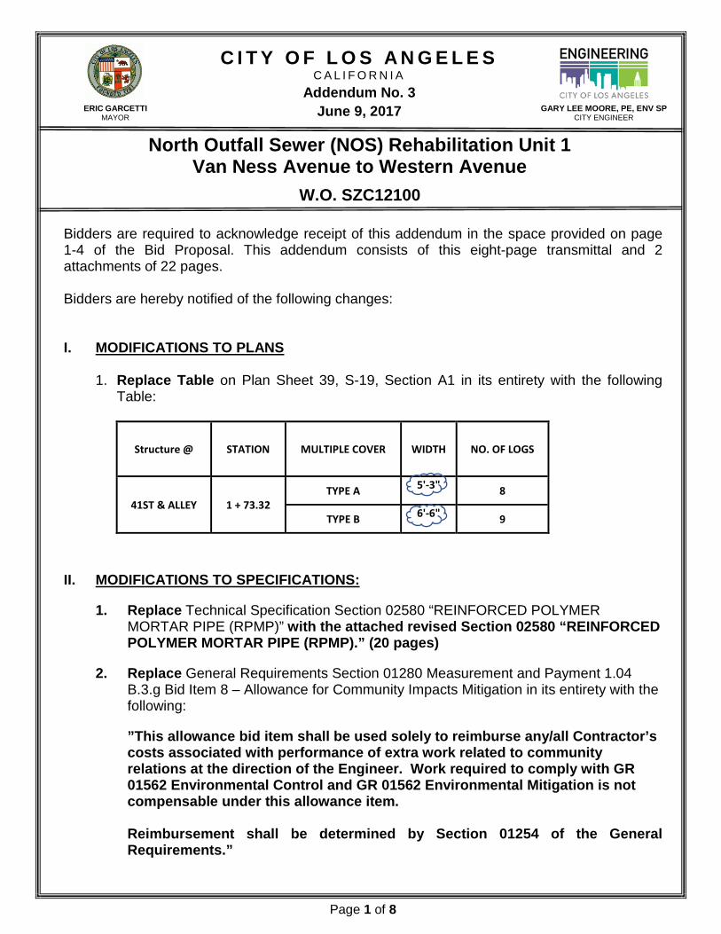
1. Replace Table on Plan Sheet 39, S-19, Section A1 in its entirety with the following
Table:
Structure @ STATION MULTIPLE COVER WIDTH NO. OF LOGS
41ST & ALLEY 1 + 73.32 TYPE A 5'-3" 8
TYPE B 6'-6" 9
II. MODIFICATIONS TO SPECIFICATIONS:
1. Replace Technical Specification Section 02580 “REINFORCED POLYMER MORTAR PIPE (RPMP)” with the attached revised Section 02580 “REINFORCED POLYMER MORTAR PIPE (RPMP).” (20 pages)
2. Replace General Requirements Section 01280 Measurement and Payment 1.04 B.3.g Bid Item 8 – Allowance for Community Impacts Mitigation in its entirety with the following:
”This allowance bid item shall be used solely to reimburse any/all Contractor’s costs associated with performance of extra work related to community relations at the direction of the Engineer. Work required to comply with GR 01562 Environmental Control and GR 01562 Environmental Mitigation is not compensable under this allowance item.
Reimbursement shall be determined by Section 01254 of the General Requirements.”
Page 1 of 8
C I T Y O F L O S A N G E L E S C A L I F O R N I A
Addendum No. 3 June 9, 2017
North Outfall Sewer (NOS) Rehabilitation Unit 1 Van Ness Avenue to Western Avenue
W.O. SZC12100
ERIC GARCETTI MAYOR
GARY LEE MOORE, PE, ENV SP CITY ENGINEER
3. Replace General Requirements Section 01280 Measurement and Payment 1.04.B.3.G Bid Item 15 – Closed Circuit Television (CCTV & Laser/Sonar Profile Report in its entirety with the following:
“First full route that covers multiple attempts due to removal of obstacles to complete televised inspection shall be submitted via CCTV in high definition color digital format with resolution no less than 720 per line, 3D sonar and laser profiling (must be completed prior to slip-liner pipe procurement), which includes reporting debris volume (total volume in tons per foot), water level (depth d/D), debris depth, gas (H2S) concentrations, existing sewer profile vs. original sewer profile. Data shall be given to the Engineer in two (2) solid state external hard drives. Each solid state hard drive shall contain identical data.”
III. QUESTIONS FROM BIDDERS (Q) AND ANSWERS FROM THE CITY (A):
(1Q) Is there any information the City may provide the bidder as to the existing condition of
the portions to be rehabilitated, i.e. CCTV CD or condition assessment reports? (1A) Yes. Please refer to Item IV. “Miscellaneous” (2Q) Regarding note 7 on drawing R-3, please provide an allowance item or a bid item
quantity for any new wye installations replacing blind wyes and tees. There is a cost to excavation, shoring and reconnecting such items to the new liner pipe. The Contractor should be fairly compensated for performing such task(s), wouldn’t you agree?
(2A) Any planned connection/reconnection has been called out on the plans. Any
additional blind wyes encountered along the alignment shall be immediately brought to the Engineer’s attention. Additional wye installations or blind wye replacements that are not indicated out on the plans will be addressed via a change order.
Page 2 of 8

C I T Y O F L O S A N G E L E S C A L I F O R N I A
Addendum No. 3 June 9, 2017
North Outfall Sewer (NOS) Rehabilitation Unit 1 Van Ness Avenue to Western Avenue
W.O. SZC12100
ERIC GARCETTI MAYOR
GARY LEE MOORE, PE, ENV SP CITY ENGINEER
(3Q) Regarding note 7 on drawing C-2, If the Contractor were to combine both Pit 1 and Pit 2 into one Access Pit, the Contactor would be compensated the bid item amounts for both the Pit 1 and Pit 2 bid items, correct?
(3A) Yes. If the Contractor was to combine both Pit 1 and Pit 2 into one access pit,
the Contactor will be compensated for both, Pit 1 and Pit 2 bid item amounts. (4Q) Specification section 01280, Measurement and Payment, describes the Bid Item 3
grout overrun allowance as only pertaining to bid items 28 and 29. However, bid item 31 for grouting the double rectangular channel is not linked to the bid item 3 allowance and has no overrun quantity defined. Would the City consider modifying the specification section 01280 grouting allowance description in Bid Item 3 to apply to bid items 28, 29, and 31? If not, please provide the over-run quantity the Contractor shall assume for bidding purposes when grouting the existing double rectangular channel.
(4A) Bid item 31 is a lump-sum bid item. Please bid accordingly. (5Q) Specification section 01721, article B requires the Contractor to provide 2 field offices
for the inspector and engineer. Please identify the onsite location of these field offices. Will the field offices be required to be located offsite due to this residential location?
(5A) The location of the field trailer/office space is to be determined by the
contractor. The location is subject to the approval of the PE and the Inspector. (6Q) The table of contents of the technical specifications identifies a geotechnical report
that was not provided in the original bid package. Please provide in an upcoming addendum
(6A) Please refer to Addendum 2 for this project. (7Q) Specification section 02310 mentions hazardous soils will be paid via an allowance.
However, there is no hazardous soil allowance within the bid form. Please add an allowance item for hazardous soils and / or confirm hazardous soils will be paid by change order if encountered.
Page 3 of 8

C I T Y O F L O S A N G E L E S C A L I F O R N I A
Addendum No. 3 June 9, 2017
North Outfall Sewer (NOS) Rehabilitation Unit 1 Van Ness Avenue to Western Avenue
W.O. SZC12100
ERIC GARCETTI MAYOR
GARY LEE MOORE, PE, ENV SP CITY ENGINEER
(7A) If any contaminated soil is encountered, the contractor will be compensated via
Bid Item # 4 (Allowance for Differing Site Conditions) (8Q) Specification section 13270 identifies an attachment A1 for the NOS Unit 1
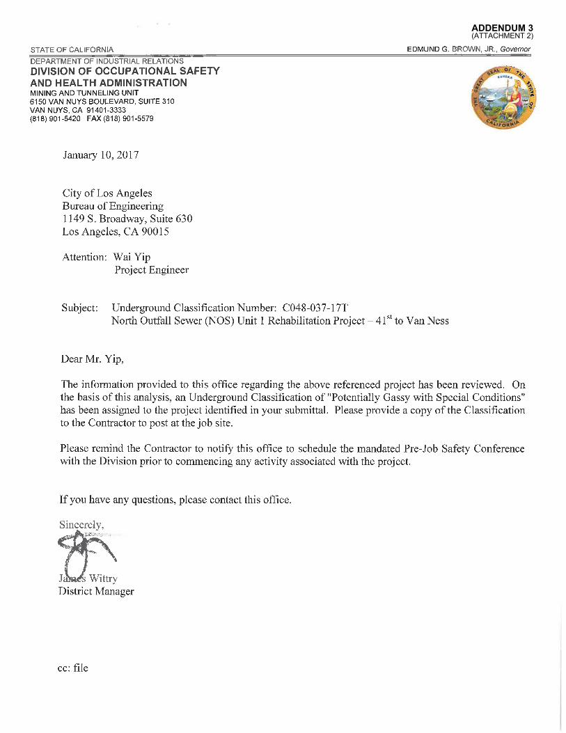
Underground Classification which was not included in the original bid package. Please provide in an upcoming addendum.
(8A) Please see Attachment 2 - Underground Classification (2 pages) (9Q) Drawing C-2 identifies two adjacent manholes to be abandoned on the North side of
41st drive just West of the Alley (Section E5 on drawing C-2). Are the two adjacent manholes on the South side of 41st Drive just west of the Alley also required to be abandoned and / or removed (Section D5 on drawing C-2)?
(9A) Only the two (2) adjacent maintenance holes on the north side of 41st Drive,
west of the alley require abandonment. (10Q)Bid Item 43 is for 2,500 SF of concrete hardscape to be replaced. The measurement
and payment section of specification (01280) states this item is for constructing new concrete hardscape as shown in the plans. However, there is no concrete hardscape shown in the plans. The Contractor will have to remove and replace the concrete hardscapes based on their means and methods which may be more than the bid quantity. Please identify the extent and location of the 2,500 SF of concrete hardscape that the City has identified to be replaced under bid item 43. Additionally, will the Contractor be compensated by the square foot under bid item 43 for all concrete hardscape that is replaced during construction?
(10A)Concrete quantities are to be determined in field and any discrepancy between
the quantity provided in bid item 43 will be addressed per change order. (11Q)Bid Item 44 is for 4 each utility pole supports. The measurement and payment
section of specification (01280) states this item is for utility poles as shown in the plans. However, no utility pole supports are shown in the plans. Please identify which utility poles the City is expecting to be supported during construction.
Page 4 of 8

C I T Y O F L O S A N G E L E S C A L I F O R N I A
Addendum No. 3 June 9, 2017
North Outfall Sewer (NOS) Rehabilitation Unit 1 Van Ness Avenue to Western Avenue
W.O. SZC12100
ERIC GARCETTI MAYOR
GARY LEE MOORE, PE, ENV SP CITY ENGINEER
(11A)As indicated on the construction notes, the Contractor shall support and protect all utility poles and trees in place within 5' of access pit area.
(12Q)Bid Item 42 is for street light conduit relocations and new pull boxes. The measurement and payment section of specification (01280) states this item is for relocations and new pull boxes as shown in the plans. However, no street light conduit relocations or new pull boxes are shown in the plans. Please identify which street light conduits and new pull boxes the City is expecting for construction.
(12A)Please refer to Street Light Plan Index D-22224, which can be viewed or
downloaded from the Bureau of Engineering’s electronic vault. (13Q)Specification Section 02580, 3.01.C.4 (Reinforced Polymer Mortar Pipe, RPMP
Manufacturing, Prototype Testing) states “Conduct all required tests in the presence of the ENGINEER and IITL as indicated and secure acceptance of results.” It is our understanding that the ENGINEER’s presence has not been required on the other recent City of LA projects. Please confirm that the Contractor’s bid price should not include money to pay for the ENGINEER to attend the Prototype Testing.
(13A)Please refer to the revised specification section 02580 “REINFORCED
POLYMER MORTAR PIPE (RPMP)” (14Q)Specification Section 01711 and drawing C-2 identify a LADWP waterline along with
3 service connections that will be relocated by others prior to the Contractor starting work. For bidding purposes, please provide the duration or date the Contractor should assume LADWP will have these services relocated?
(14A)As indicated on Sheet R-3 (Note 25) of the plans, the Contractor is advised to
expect a time frame of approximately 4 to 6 months for LADWP to relocate its water utilities.
(15Q) Specification Section 01711 and drawing C-2 identifies a SoCal gas line that will be
relocated by others prior to the Contractor starting work. For bidding purposes, please provide the duration or date the Contractor should assume SoCal Gas will have these services relocated?
Page 5 of 8

C I T Y O F L O S A N G E L E S C A L I F O R N I A
Addendum No. 3 June 9, 2017
North Outfall Sewer (NOS) Rehabilitation Unit 1 Van Ness Avenue to Western Avenue
W.O. SZC12100
ERIC GARCETTI MAYOR
GARY LEE MOORE, PE, ENV SP CITY ENGINEER
(15A) As indicated on Sheet R-3 (Note 26) of the plans, the Contractor is advised to expect a time frame of approximately 4 to 6 months for the Southern California Gas Company to relocate its gas line.
(16Q)Is the Contractor required to clean and remove debris from the double rectangular
channel prior to grouting? If so, please increase the bid quantity to reflect the additional footage.
(16A)The contractor is not required to clean and remove debris from the double
rectangular chamber prior to grouting. (17Q)Is the Contractor required to perform CCTV or Laser / Sonar Profiling for the double
rectangular channel prior to grouting? If so, please increase the bid quantity to reflect the additional footage.
(17A)The contractor is not required to perform CCTV or Laser/Sonar Profiling for
the double rectangular chamber prior to grouting. (18Q)The Los Angeles effective tax rates jumps from 8.75% to 9.25% on July 1st 2017 as
a result of the passage of measure M. Please confirm bidders shall utilize the new tax rate of 9.25% effective on July 1st in bidding this project and change orders will NOT be granted post bid for the difference between the current and new July 1st tax rate.
(18A)Bidders shall utilize the new tax rate of 9.25% effective on July 1st, 2017 for their bid computations.
(19Q)Following review of the Contract Documents it is unclear if the following new 5’ diameter trap manholes at Stations (0+24.25), (0+23.25), & (0+32.75) depicted on drawing C-11 and included under bid item 37 require the protective lining. Please confirm if these manholes shall receive a protective lining or not.
(19A)All new Manholes including the manholes at Stations (0+24.25), (0+23.25), &
(0+32.75) require a Type I protective lining.
(20Q)Please confirm the road section to be reinstalled in the pit areas and other areas that our damaged during construction. Is the City expecting a 4”, 6”, 8” section of asphalt
Page 6 of 8

C I T Y O F L O S A N G E L E S C A L I F O R N I A
Addendum No. 3 June 9, 2017
North Outfall Sewer (NOS) Rehabilitation Unit 1 Van Ness Avenue to Western Avenue
W.O. SZC12100
ERIC GARCETTI MAYOR
GARY LEE MOORE, PE, ENV SP CITY ENGINEER
over aggregate base to be replaced by the Contractor? Also, please confirm Bid Item 47 is for temporary asphalt surface ONLY and the permanent asphalt resurfacing is to be including in the lump sum price.
20A) Please check the respective roadway classifications in NavigateLA and determine the standard pavement sections as indicated on the section E422.116 of the Street Design Manual. Item 47 is only for the temporary asphalt surfaces. 21Q) Drawing S-18, detail E-1 shows a cross sectional view of the new junction structure. The detail also indicates the Contractor is to provide and install a 36” Flexible Coupling to connect to and extend the existing 36” VCP. Please provide the details, type, and requirements for this 36” flexible coupling. 21A) The Contractor shall submit the coupling for review during construction phase. The proposed flexible couplers must be per City of L.A. approved products. 22Q) Drawing R-4, note 29.B, third paragraph, states steel casing shall be used to facilitate drilling and support of drilled holes for temporary shoring. Is full depth steel casing required for all drilled holes? OR is steel casing required for only partial hole depth, specifically the top section of the hole through potential pipe bedding / zone sections of adjacent utilities? 22A) Full depth steel casings are recommended. If partial casings are used, any cave-in during the construction shall be back filled with slurry immediately and re-drilled at some other time. 23Q) Are there provisions in place for LADWP to relocate or cover the overhead powerlines which are located directly over access pit 2 prior to Work? 23A) Per call-out on C-2 Sheet, overhead power lines are to be protected in place.
IV. MISCELLANEOUS
This project contains a DVD that include the associated CCTV inspections, CCTV log sheets and the Condition Assessment Report, which are mandatory for all
Page 7 of 8

C I T Y O F L O S A N G E L E S C A L I F O R N I A
Addendum No. 3 June 9, 2017
North Outfall Sewer (NOS) Rehabilitation Unit 1 Van Ness Avenue to Western Avenue
W.O. SZC12100
ERIC GARCETTI MAYOR
GARY LEE MOORE, PE, ENV SP CITY ENGINEER
prime contractor bidders. Due to the size of the files, these materials will not be available for downloading from the City of Los Angeles’ Business Assistance Virtual Network. They may be picked up, or they may be shipped at the recipient’s request. As a general rule, each planholder is allowed to receive one set. Please note that only these DVDs are available for pickup or shipment. All other materials in the bid package must be downloaded from the City of Los Angeles’ Business Assistance Virtual Network (www.labavn.org). A. Pick Up
The DVDs will be available for pick up Monday through Friday from the Wastewater Conveyance Engineering Division Reception Desk, 1149 S. Broadway, Suite 630, Los Angeles, CA 90015, between the hours of 7:00 am and 5:00 pm.
B. Delivery
DVDs may be shipped at the planholder’s request and at their expense. The request should be faxed to (213) 847-0703 or emailed to [email protected]. It must contain the company’s name, physical address, phone number, and name of the person to whom it will be shipped. It also must contain a valid account number for a delivery provider, such as FedEx or UPS, so that the package can be shipped “Bill Recipient”. For same-day shipping, all requests must be received by 1:00 pm, Monday through Thursday. Requests received after 1:00 pm on Thursday will be shipped the first day of the following week.
C. Additional Information
Those needing further information or assistance may call Richard Pedrozo during the hours given above at (213) 485-1638 or send an email to [email protected].
Sincerely, _____________________________ Edick Ohanian, PE, ENV SP Division Engineer Project Award and Control Division Bureau of Engineering
Page 8 of 8

NOS Rehabilitation Unit 1 – Van Ness To Western SZC12100 [04/26/16]
REINFORCED POLYMER MORTAR PIPE (RPMP) DIVISION 2
02580-1
SECTION 02580
REINFORCED POLYMER MORTAR PIPE (RPMP)
PART 1 - GENERAL
1.01 DESCRIPTION
A. The CONTRACTOR shall furnish all tools, equipment, materials, and supplies and shall perform all labor required to complete the work as indicated in the Contract Documents.
B. This Section covers the use of round and non-round Reinforced Polymer Mortar Pipe (RPMP) in the construction of sewers, storm drains, and related structures in direct burial and slipline installations subject to the limitations of the individual City approved products.
1.02 RELATED WORK SPECIFIED ELSEWHERE
A. Section 01330, Shop Drawings/Submittals.
B. Section 01453, Sampling, Testing, and Fabrication Inspection
C. Section 01783, Record Drawings and Record Project Manual
D. Section 02431, Annular Space Grouting
1.03 REFERENCE STANDARDS
A. ASTM Standards:
1. ASTM A240 – Standard Specification For Chromium and Chromium-Nickel Stainless Steel Plate, Sheet, and Strip for Pressure Vessels and for General Applications.
2. ASTM C877 – Standard Specification For External Sealing Bands for Concrete Pipe, Manholes, and Precast Box Sections.
3. ASTM C1103 – Standard Practice for Joint Acceptance Testing of Installed Precast Concrete Pipe Sewer Lines.
4. ASTM C1244 – Standard Test Method for Concrete Sewer Manholes by the Negative Air Pressure (Vacuum) Test Prior to Backfill
5. ASTM D256 – Standard Test Methods for Determining the Izod Pendulum Impact Resistance of Plastics
6. ASTM D638 – Standard Test Method for Tensile Properties of Plastics.
7. ASTM D695 – Standard Test Method for Compressive Properties of Rigid Plastics.
8. ASTM D790 – Standard Test Methods for Flexural Properties of Unreinforced and Reinforced Plastics and Electrical Insulating Materials.
9. ASTM D2240 – Standard Test Method for Rubber Property – Durometer Hardness.
ADDENDUM 3
(Attachment 1)

NOS Rehabilitation Unit 1 – Van Ness To Western SZC12100 [04/26/16]
REINFORCED POLYMER MORTAR PIPE (RPMP) DIVISION 2
02580-2
10. ASTM D2290 - Standard Test Method for Apparent Hoop Tensile Strength of Plastic or Reinforced Plastic Pipe by Split Disk Method.
11. ASTM D2412 – Standard Test Method for Determination of External Loading Characteristic of Plastic Pipe by Parallel Plate Loading.
12. ASTM D2583 – Standard Test Method for Indentation Hardness of Rigid Plastics by Means of a Barcol Impressor.
13. ASTM D3262 – Standard Specification for “Fiberglass” (Glass-Fiber-Reinforced Thermosetting-Resin) Sewer Pipes.
14. ASTM D3567 – Standard Practice for Determining Dimensions of “Fiberglass” (Glass-Fiber-Reinforced Thermosetting-Resin) Pipe and Fittings.
15. ASTM D4161 – Standard Specification for “Fiberglass” (Glass-Fiber-Reinforced Thermosetting-Resin) Pipe Joints Using Elastomeric Seals.
B. American Water Works Association (AWWA)
1. AWWA M45 – Fiberglass Pipe Design.
C. Others
1. Standard Specifications For Public Works Construction (SSPWC, or Green Book) as modified by City of Los Angeles “Brown Book”, latest edition.
2. ISO 178 – Plastics – Determination of Flexural Properties.
3. DIN EN 13566-4 : 2003-04 - Plastics piping systems for renovation of underground non-pressure drainage and sewerage networks
1.04 DEFINITIONS
A. EPS: Equivalent Pipe Stiffness: The pipe stiffness as defined per ASTM D2412, except stiffness factor relationship and direct correlation does not apply.
B. IITL: Independent Inspector or Testing Laboratory
C. Lot: All pipes having the same production marking number and of the same shape in both cross-section and longitudinal curvature. Also, it shall not exceed 50 pipes or 1,000 feet of pipe, whichever occurs first.
D. NR: Non-Round
1.05 RPMP PIPE SYSTEM DESCRIPTION
A. The pipe shall be manufactured using a mandrel process utilizing continuous glass fiber reinforcements in the circumferential direction. For a hand laid process, pipe shall be manufactured using a mandrel process utilizing unidirectional glass fiber reinforcements in both the longitudinal and circumferential directions. For a centrifugal casting
ADDENDUM 3
(Attachment 1)

NOS Rehabilitation Unit 1 – Van Ness To Western SZC12100 [04/26/16]
REINFORCED POLYMER MORTAR PIPE (RPMP) DIVISION 2
02580-3
process, pipe shall be manufactured in conformance with SSPWC 207-20. Both continuous glass fiber roving and chopped roving may be incorporated to achieve hoop strength and axial reinforcement but consistent with the approved product requirements. A reinforced polymer mortar layer shall be used to provide increased stiffness with placement near the neutral axis in the core.
B. The pipe shall be manufactured in accordance with ASTM D3262 and meet the cell characteristics approved under the individual product qualification testing, with the following exceptions:
1. The pipe may be manually made using a City approved method and production plant.
2. The pipe lengths may vary from those stated in Section 6.2.2 upon approval by the ENGINEER.
C. Inner surface, cut surfaces, and any and all surfaces subject to exposure of a sewer environment shall have a protective lining comprise of a chemical resistant vinyl ester resin approved as part of the individual product qualification testing and approval process.
D. The pipe shall be field connected using product approved joint systems that utilize compressed elastomeric sealing gaskets as the sole means to maintain joint water tightness. Where cut-to-fit pipe pieces are specifically called out in the contract drawings such as to accommodate T-Section pipe specials, the CONTRACTOR may use gasketed external couplings in lieu of conventional joints, provided they conform to ASTM C877 Type II, vacuum test per ASTM C1244, and as a minimum encased in concrete per Standard Plan S-333-0. In addition, cut ends shall be coated with approved protective lining system. This approach shall not be used for repair of damaged joints. Pipes with damaged joints shall be replaced in kind.
1. Standard Plan S-333-0 shall be modified as follows:
a. Concrete Class shall be 650-CW-4000
E. For curved portions of an alignment of pipe rehabilitation projects only, installed via open cut with top of host pipe removed, the CONTRACTOR may use gasketed external couplings in lieu of conventional joints, provided they conform to ASTM C877 Type II, vacuum test per ASTM C1244, and as a minimum encased in concrete per Standard Plan S-333-0. In addition, pipe ends shall be mitered, connected flush, and coated with approved protective lining system.
1. Standard Plan S-333-0 shall be modified as follows:
a. Concrete Class shall be 650-CW-4000]
F. For curved portions of an alignment of pipe rehabilitation projects only, installed via sliplining, the CONTRACTOR may construct a special section where adjoining pieces are mitered, connected continuously flush, and are fiberglassed together. CONTRACTOR to provide ENGINEER with submittal and receive approval before commencement
ADDENDUM 3
(Attachment 1)

NOS Rehabilitation Unit 1 – Van Ness To Western SZC12100 [04/26/16]
REINFORCED POLYMER MORTAR PIPE (RPMP) DIVISION 2
02580-4
of work. Glassing of the joint shall be solid from intrados to extrados of the pipe wall with sufficient overlap along each pipe edge. No more than 3 segments shall be used to make up a final piece. Final piece shall use gasketed joints as sole means of sealing to adjacent pipe. Angulation of mitered joint to be 15° or less. Segments for curve shall be mitered at the manufacturer’s approved plant using pre-approved material. Two (2) of each type/configuration of special sections shall be selected for testing by the Independent Inspector/Engineer. The special section shall be tested using the methods of ASTM D4161 SS 7.4. The initial vacuum shall be -5.0 psi (-34.5 kPa) and the permissible pressure increase shall be 0.1 psi (690 Pa) during the seal off period. An alternate test method may be proposed by the CONTRACTOR for consideration by the ENGINEER. In addition, cut ends shall be coated with an approved protective lining system.
G. Pipe Joints: Gasketed joint coupling, flush type, as appropriate for the intended means of installation, with o-ring gaskets. Gaskets shall either be affixed to the pipe by means of a suitable adhesive or shall be installed in such a manner so as to prevent the gasket from rolling out of the precut groove.
H. Fittings and specials shall be fabricated from pipe meeting the requirements of these specifications.
I. Contractor-responsible element design for non-round shapes:
1. The CONTRACTOR shall engage the services of a pre-approved RPMP manufacturer to establish the required thickness and composition for non-round shapes based on the following criteria:
a. Conform to the profile shown on the contract drawings. For non-round shapes, the manufacturer is permitted to introduce a slight curvature to the straight sides of the shape(s) shown in the contract drawings when required for manufacturing; however, arch depth shall not exceed ½-inch.
b. Demonstrate the pipe has sufficient stiffness and strength to support the loads and load combinations shown on the contract drawings without exceeding the approved material properties, strain & stress and deflection limits, or result in damage to the pipe walls.
c. Have a uniform cross-section that meets the minimum (EI) stiffness factor value listed on the contract drawings.
d. Pipe shall meet the minimum Equivalent Pipe Stiffness (EPS) listed on the contract drawings.
e. Maximum long-term deflection shall not exceed the permitted 3.75% deflection of the vertical dimension of RPMP as shown on Table 211-41.3A in the City of LA Structural Design manual.
f. Able to support the Contractor’s installation requirements, including handling, jacking/pushing, and grouting.
ADDENDUM 3
(Attachment 1)
NOS Rehabilitation Unit 1 – Van Ness To Western SZC12100 [04/26/16]
REINFORCED POLYMER MORTAR PIPE (RPMP) DIVISION 2
02580-5
2. The CONTRACTOR shall proceed with the design, manufacturing, testing, delivery, and installation of the non-round shape(s) in a methodical manner such as listed below to ensure proper evaluation of the Contractor’s use of this system.
a. Pipe Design: Prepare preliminary design using calculations to establish the pipe profile & thickness based on pre-approved methods by the City through the product’s pre-qualification process, and/or Finite Element Analysis (FEA) Methods using software that conforms to the requirements in this specification. When no pre-approved method exists, the FEA method shall be used. City approved allowable material values shall be used and profile(s) shall match that provided in the contract documents. FEA modeling shall conform to the following conditions:
1) General Modeling: The FEA modeling shall consist solely of the slipline pipe. Use short-term allowable material values. Loads for General Model shall be per the Contract Drawings. Do not model host or grout. Boundary/support conditions shall be pinned-type and limited to bottom [4°] of the shape. However, the following exceptions are permitted:
a) Some or all Pinned-Type bottom supports may be replaced with uni-directional supports. Model must nevertheless remain stable.
b) Top and side surfaces may be provided with radial and tangential “soil” springs based on information listed in the Contract Structural Drawings.
2) Long-Term Deflection Modeling: Similar to General Modeling except using long-term approved allowable material values. Target Long-Term deflection shall be per the Contract Structural Drawings.
3) EPS Modeling: The FEA modeling shall consist solely of slipline pipe. Boundary/support conditions shall seek to mimic support conditions present during the parallel plate test per ASTM D2412. Point load representing actuator may be distributed to a width of 2 inches to mimic contact plate at crown of pipe. Load for EPS is that which is required to achieve a 5% deflection of max vertical dimension.
b. Pipe Prototype: Based on the pipe design above, manufacture a pipe prototype, representative of the production pipes, with continuous inspection by the IITL.
ADDENDUM 3
(Attachment 1)

NOS Rehabilitation Unit 1 – Van Ness To Western SZC12100 [04/26/16]
REINFORCED POLYMER MORTAR PIPE (RPMP) DIVISION 2
02580-6
This pipe shall be subsequently used for pipe design verification.
c. Pipe Design Verification:
1) Material Verification: Conduct the required material tests to show the prototype pipe meets or exceeds all the minimum material property requirements.
2) Design Verification: Prepare the necessary calculations to show the prototype cross-section meets the minimum sectional stiffness factor (EI). Also, conduct the required physical test to show the prototype pipe meets the minimum Equivalent Pipe Stiffness required. In addition, when conducting EPS test, instrument the pipe if any of the following conditions apply:
a). The RPMP shape has no prior use in the City of Los Angeles.
b). Finite Element Analysis (FEA) method was used as the primary basis to design the pipe.
c). No pre-approved analysis method exists for the design of the project shape.
3) Installation Loads Verification: Prepare calculations showing stresses and strains resulting from the proposed installation loads, including any annular space grouting, jacking, pulling, etc., do not exceed allowable product material values.
4) Where any of the above items are not met, the shape shall be redesigned and a new prototype and pipe design verification phase shall be conducted.
d. Production Pipe: Commence pipe production based on approved prototype thickness and composition, including lot testing.
e. Delivery & Installation: Deliver & install pipe released for such use by the INSPECTOR. Pipe is still subject to rejection until final inspection.
1.06 SUBMITTALS
A. General:
1. Prepare in accordance with Section 01330, and Contract Drawings.
2. Product Data: Manufacturer's product information, including handling and storage recommendations, and material safety data sheets for all materials making up the pipe.
ADDENDUM 3
(Attachment 1)

NOS Rehabilitation Unit 1 – Van Ness To Western SZC12100 [04/26/16]
REINFORCED POLYMER MORTAR PIPE (RPMP) DIVISION 2
02580-7
3. Verification test data, including material certification and testing data.
4. Certifications indicating compliance with reference standards.
5. Provide individual submittals for each pipe size.
6. All information shall be provided using either English units or dual English/Metric units.
7. Prior to providing any pipe submittal, the CONTRACTOR shall arrange and conduct a Pipe Inspection & Submittal meeting with the ENGINEER and INSPECTOR to discuss details particular to the upcoming work. See Section 01453 for additional requirements.
B. Shop Drawings:
1. Product Data Information:
a. Planned Application.
b. Planned Installation.
c. Product Description and Composition.
d. Dimensions (external, internal along pipe barrel and at joint, thickness).
e. Sectional properties along pipe barrel and at joint (Area, Ix, Iy, Sxtop, Sxbot).
f. Section Lengths.
g. Weight & density.
h. Joint type, including gasket material, and intended load path through joint, in axial direction.
i. Joint details, including design pull/gap limits, design deflection limits, and offset limits.
j. Pipe jointing recommendations, including field verification methods
k. Dimensions, cut angle(s), glassing & cutting procedure, and all materials used for constructing mitered Specials for curved alignments per 1.05.E.
l. Grout port details, spacing, and port repair (as applicable).
m. Pipe Stiffness (for non-round pipes, list equivalent pipe stiffness).
n. Certification of Compliance.
o. Pipe handling recommendations.
p. Proposed repair procedures for each type of repair, including documentation on all materials used, curing times required, and final surface finish.
2. Verification Data (Quality Assurance/Quality Control Submittals):
ADDENDUM 3
(Attachment 1)

NOS Rehabilitation Unit 1 – Van Ness To Western SZC12100 [04/26/16]
REINFORCED POLYMER MORTAR PIPE (RPMP) DIVISION 2
02580-8
a. Material Certification.
b. Independent Inspector
1) Documentation of at least two qualified personnel. If qualified, the INSPECTOR will identify primary and backup personnel of those submitted for consideration.
c. Testing Laboratory Documentation
1) Documentation showing proposed laboratory(s) is approved by the City’s Engineer of Design to conduct the proposed tests.
2) Test plan from each laboratory delineating which tests will be performed.
d. General Testing & Dimension Data Report & Summary
1) General testing data and result summaries per Section 1.07.C.3 of this specification.
2) Pipe acceptance tests and dimension verification results per SSPWC 207-20.7 except as modified in 1.07.C.4 of this specification.
3) Rubber gasket testing data.
4) Hoop and axial compression testing results.
5) Hoop and axial tensile testing results – axial tensile for information only.
6) Joint test results.
7) Equipment calibration documentation.
e. Axial / Thrust Analysis Report for slipline/jacked-pipe installations per Section 1.07.E.7 of this specification.
f. Pipe Repair Reports
1) Detailed report for each repaired pipe, with signature and concurrence by IITL of both procedure and applicability.
3. Fittings and specials
a. Provide detailed dimensioned shop drawings, manufacturing method, and product information. Include special handling and installation requirements.
4. Pipe production and laying schedule
5. Field coating kit contents with application procedure for use in coating exposed/cut surfaces of pipes at non-solid vinylester sections.
C. Written Notifications
1. Start of Prototype Pipe Construction, 15 days prior to event.
2. Start of production run, 15 days prior to event
ADDENDUM 3
(Attachment 1)

NOS Rehabilitation Unit 1 – Van Ness To Western SZC12100 [04/26/16]
REINFORCED POLYMER MORTAR PIPE (RPMP) DIVISION 2
02580-9
3. Start of Lot testing, 21 days prior to event
D. Additional Submittals For Non-Round (NR) Shapes
1. Pipe Design
a. Detailed description, narrative, and CADD drawings showing conformance to all the required design criteria.
b. Design calculations:
1) Demonstrate proposed profile, composition, and uniform thickness conforms to all the required design criteria as indicated in the contract documents, including the capability to support the design and construction loads without exceeding the approved material values.
2) Calculations shall be signed and stamped by a California registered Civil or Structural Engineer.
3) City approved material values (allowable) shall be used in this step of the process.
4) Use only appropriate ASTM, AWWA standards, and mechanics of materials based methods pre-approved by the City through the product’s pre-qualification process, and/or Finite Element Analysis (FEA) Methods using software that conforms to the requirements in this specification. When no pre-approved method exists, only the FEA method shall be used.
5) Profile(s) shall match that provided in the contract documents.
2. Prototype Pipe
a. Independent inspection reports verifying cross-sectional dimensions of the pipe mandrel for each proposed shape.
b. Independent inspection report verifying construction of shape(s) conforms to the proposed profile, composition, and thickness of the approved pipe design submittal.
3. Testing Reports
a. All testing & Instrumentation protocol for NR sections 15 days prior to testing.
b. NR Initial Flexural Modulus & Stiffness Factor Verification Report.
c. NR Equivalent Pipe Stiffness Testing Report.
d. NR Instrumented Equivalent Pipe Stiffness Testing Report as per Section 1.07.F of this specification section.
e. NR Joint Test Report.
ADDENDUM 3
(Attachment 1)

NOS Rehabilitation Unit 1 – Van Ness To Western SZC12100 [04/26/16]
REINFORCED POLYMER MORTAR PIPE (RPMP) DIVISION 2
02580-10
4. Analysis Reports:
a) Axial Thrust Analysis Report.
E. Field Testing
1. Line Testing Procedure and Equipment (when applicable).
2. Field Joint Testing Procedure and Equipment (when applicable).
F. As-Built Drawings
1. In conformance with Section 01783 and this Section.
2. For EI and EPS listed on the contract drawings, show as strikethrough and list mean value minus one (1) standard deviation based on the approved lots and prototype pipe tests. Submit calculations for review and acceptance by the ENGINEER. ENGINEER may choose to list alternate lower value at their discretion.
1.07 QUALITY ASSURANCE
A. Qualifications for IITL
1. Testing Laboratory: Approved by the City of Los Angeles Engineer of Design to conduct the required tests under this specification. The approval shall have been made in writing within 12 months from the start of this contract.
2. Laboratory Plastic Pipe Testing Technician: Retained by the Testing Laboratory with two (2) years minimum experience in conducting all the required plastic pipe lab tests or similar tests.
3. Independent Inspector: Individual shall have five years minimum experience in conducting all the specified inspection and when required by the INSPECTOR – see SSPWC Section 4-1 for additional requirements as modified by the “Brown Book” and Section 01453.
4. INSPECTOR approval of Independent Inspector is required.
B. Workmanship
1. Workmanship shall conform to that required per SSPWC 207-20 and ASTM D3262.
2. Contractor selected RPMP manufacturer may submit proposed repair procedure conducted at the place of manufacturing for minor imperfections for consideration by the ENGINEER. However, the following imperfections will be considered injurious and cause for rejection of the individual pipe or lot:
a. Defects including indentations, bubbles, pinholes, cracks, pits, blisters, gouges, foreign inclusions and resin starved areas that, due to their nature, degree of extent, detrimentally affect the strength and serviceability of the pipe. The pipe shall be as uniform as commercially practical in color, ovality, density, and other physical properties.
ADDENDUM 3
(Attachment 1)
NOS Rehabilitation Unit 1 – Van Ness To Western SZC12100 [04/26/16]
REINFORCED POLYMER MORTAR PIPE (RPMP) DIVISION 2
02580-11
b. Bulges, dents, ridges, and other defects that result in a variation of inside diameter of more than 1/8 inch from that obtained on adjacent unaffected portions of the surface. No glass fiber reinforcement shall penetrate the interior surface of the pipe wall.
c. For each pipe, frequency of individual repairs exceed 1% of the surface area, surface area of the repair on the body of the pipe exceeds two (2) square inches, and or the number of pipes needing any type of repair exceed 10% of a lot. Repair to any portion of the joint area shall not exceed one (1) occurrence per joint, each occurrence shall not be greater than two square inches of surface area, and all occurrences shall not exceed 5% of the total joints areas per lot, assuming two joint areas per pipe.
d. A pre-approved comparator tablet may be used as reference when evaluating these conditions.
3. All potential repairs shall be brought to the attention of the IITL for general consideration as potential candidates for repair. However final approval must be obtained from the ENGINEER before any repair is implemented.
C. Verification & Project Qualification Tests
1. All tests shall be conducted by an approved laboratory plastic pipe testing technician, at an approved Testing Laboratory, and witnesses by the Independent Inspector, with individual sets for each pipe size required.
2. These tests and associated reports shall be completed to the satisfaction of the INSPECTOR and ENGINEER prior to starting production run. However, production run shall not deviate in any way from the sections qualified under these tests.
3. General Testing: Conduct and report on the required pipe tests in accordance with SSPWC 207-20, 207-22, and Section 500 except as modified by the Brown Book and the following modifications:
a. Testing Data reported shall be for the particular pipe being provided and not archived data.
b. For round pipes, results from parallel plate test to compute pipe stiffness (and stiffness factor) per ASTM D2412 at 5% deflection as modified by ASTM D3262, may be used to obtain item 2), “Initial Flexural Modulus (ASTM D790)”, of the Testing Data requirements of 207-20, 207-22 of the Brown Book. Flexural Modulus shall be obtained at 5% deflection. For NR Pipe, see 1.07.D.2.
c. Results from Barcol Impressor per ASTM D2583 may be used to fulfill item 4), “Impact Strength (ASTM D256) or Shore D Hardness (ASTM D2240)”, of the Testing Data requirements of 207-20, 207-22 of the Brown Book.
ADDENDUM 3
(Attachment 1)

NOS Rehabilitation Unit 1 – Van Ness To Western SZC12100 [04/26/16]
REINFORCED POLYMER MORTAR PIPE (RPMP) DIVISION 2
02580-12
4. Required pipe acceptance tests and dimension verification will be performed per SSPWC 207-20.7 for each lot except that the variation limit of Section 6.2.3 of ASTM D3262 shall be 92%. However, inner protective liner/coating thickness to maintain 100% compliance with the minimum permissible limit established during the product qualification process.
5. Rubber gasket testing information shall show compliance with SSPWC Section 208 as modified by the Brown Book and be based on tests conducted within the last two (2) years, for the actual material being provided.
6. Hoop and axial compression testing per ASTM D695.
7. Tensile testing per ASTM D638 or ASTM D2290 performed in the hoop direction. Tensile testing per ASTM D638 in the axial direction.
8. Conduct joint testing per ASTM D4161 for each pipe size. Documentation shall clearly indicate gap width, deflection angle(s), pressure(s), time intervals & durations, and equipment used. Also, include joint qualification data generated during the product approval testing.
a. Exception: For slipline installations, only hydrostatic and vacuum pressure re-testing per Section 7.1.2 & Section 7.4 of ASTM D4161 is required
D. Additional Verification & Project Qualification Tests for Non-round Shapes:
1. All reports shall be prepared, signed and sealed by a California registered Civil or Structural Engineer.
2. NR Initial Flexural Modulus Testing: Conduct three-point loading tests in conformance with ASTM D790 Procedure A, using twice the minimum number of samples required under Section 8.2 of the Standard. Record displacement as the test progresses. However, ensure to establish data points for the following three displacement targets: 2.5%, 3%, and 5%. Test all samples to rupture. General Testing Modification: When only ASTM D2290 is possible to comply with the hoop tensile testing requirement of 1.07.C.7, CONTRACTOR may fabricate representative circular pipe section with provided thickness, composition and number of layers, roving orientation, etc., is the same as that of the project pipe. In addition, to account for sample curvature, conform to the following requirements:
a. Samples shall be taken from a prototype specimen of the proposed pipe at a location which contains the least curvature in both lengthwise and cross-wise direction per Section 8.2.
b. Load half of the specimens in the concave direction and the other half in the convex direction. Final reported value shall be determined based on mean minus one (1) standard deviation.
ADDENDUM 3
(Attachment 1)

NOS Rehabilitation Unit 1 – Van Ness To Western SZC12100 [04/26/16]
REINFORCED POLYMER MORTAR PIPE (RPMP) DIVISION 2
02580-13
c. Alternatively, test in a convex configuration and account for curvature using a rational analysis in accordance with well-established principles of mechanics similar to those listed in ISO 178 and/or DIN EN 13566-4: 2003-04.
3. NR Parallel Plate Testing: Conduct a parallel plate test per ASTM D2412 to 5% deflection of a section of each prototype pipe(s) with a “ring” length not less than 12-inches. Results shall be used to establish the shape(s)’ Equivalent Pipe Stiffness (EPS). Correction factor “C” per Appendix X2 of ASTM D2412 may not be used in computing the final PS value.
4. NR Instrumented Parallel Plate Testing: Conduct an instrumented parallel plate test per ASTM D2412 to 5% deflection of a section of each prototype pipe(s) for evaluating the strains of the cross-section at “points of interest” as well as to observe if any undesirable failure modes occur. Test shall conform to the following requirements:
a. Commence by preparing a testing and instrumentation protocol detailing the configuration of the “points-of-interest” being instrumented with strain gages, load rate, strain tracking equipment to be used, means of recording the data, steps that will be followed to initially verify the accuracy of the test data, and date of proposed test.
1) A minimum of ten (10) “points-of-interest” shall be used for semi-elliptical shapes. At least five (5) shall be located at the bottom and at least three (3) at the top.
2) A minimum of eight (8) “points-of-interest” shall be used for all other shapes. At least three (3) shall be located at the bottom and three (3) at the top.
b. Notify the INSPECTOR and ENGINEER at least 15 working days, in writing, prior to conducting the test.
c. Two days prior to test, review protocol with the IITL and confirm conformance to ASTM D2412, equipment functionality and accuracy, and conduct a pretest not to exceed 1% deflection. Address all corrections and comments by the IITL and prepare for actual test.
5. NR Joint Test: Conduct joint test per ASTM D4161 for each shape (semi-elliptical, elliptical, oval, etc.) except as modified by product specific approval requirements. Documentation shall clearly indicate gap width, deflection angle(s), pressure(s), time intervals & durations, and equipment used. Also include joint qualification data generated during the product approval testing
a. Exception: For slipline installations, only hydrostatic and vacuum pressure re-testing per Section 7.1.2 & Section 7.4 of ASTM D4161 is required.
ADDENDUM 3
(Attachment 1)

NOS Rehabilitation Unit 1 – Van Ness To Western SZC12100 [04/26/16]
REINFORCED POLYMER MORTAR PIPE (RPMP) DIVISION 2
02580-14
6. Conduct tests in the presence of the IITL.
E. General Testing, Pipe Acceptance, & Analysis Reports:
1. All test results shall be presented via a testing report.
2. All test reports shall clearly identify all pertinent test standard(s) followed, equipment used, associated calibration certifications, date and time of test, and lead personnel performing the test. Report(s) shall be signed and dated by lead testing technician conducting the test.
3. Test procedures and physical results shall be thoroughly documented, including photographs, as part of quality control.
4. Reports shall clearly summarize the results of the test, denote any deviation from the related standard, and show that the results meet or exceed the required values and/or performance levels.
5. Raw data shall be included with all reports.
6. If calculations are required to demonstrate conformity to the contract requirements, report shall be signed and stamped by a California registered Civil or Structural engineer.
7. Axial Thrust Analysis Report: Prepare a report showing the maximum straight jacking/pushing forces planned by the CONTRACTOR do not exceed the allowable material properties of the pipe when the required safety factor is applied nor lead to any damage or loss of joint quality.
F. Additional Non-Round Shapes Testing & Analysis Reports:
1. NR Preliminary Design Report Using FEA
a. A complete software input file, including all associated libraries, links, batch files, open source modifications, etc., that would allow the City to re-run and reproduce the output results being submitted by the pipe manufacturer should the City decide to verify the analysis.
b. Legal copy of pertinent software manual necessary to review the output file submitted in both hard copy and electronic version.
c. Output file, in English units, listing principal stresses and strains, and global deformation results.
d. Graphical representation of model, including loading, imposed boundary conditions, undeformed and deformed shape, color coded strain results, color coded stress results, and color coded deformation results.
e. Design/Capacity (D/C) ratios and associated explanation.
2. NR Initial Flexural Modulus & Stiffness Factor Verification Report:
ADDENDUM 3
(Attachment 1)
NOS Rehabilitation Unit 1 – Van Ness To Western SZC12100 [04/26/16]
REINFORCED POLYMER MORTAR PIPE (RPMP) DIVISION 2
02580-15
a. Present the comparison between the initial flexural modulus, E, from measured three-point load sample testing of the proposed pipe specimens and the minimum required flexural modulus of the pre-approved product. The flexural modulus obtained from tests shall be shown to meet or exceed the required minimum value.
b. Demonstrate the resulting Stiffness Factor (EI) meets or exceeds the minimum requirements indicated in the contract documents. When computing the moment of inertia, I, the protective liner coating on the intrados of the pipe shall be included in the computation.
3. NR Equivalent Pipe Stiffness Report
a. Demonstrate the resulting Equivalent Pipe Stiffness factor (EPS) meet or exceed the requirements in the contract document.
4. NR Instrumented Equivalent Pipe Stiffness Testing Report:
a. Similar to the above except include figure with "points of interest" identified, and strain and deflection data in both hard copy and in digitized format.
b. Tabulated strain values at 2%, 3%, and 5% deflection for each of the “points-of-interest”.
c. Photographs depicting deformed shape at 2%, 3%, and 5% deflection.
5. NR joint report:
a. Report must include detailed information regarding the equipment, deflection angle, loading, test duration, gap width, pictures, result summaries, and verification by IITL of successful tests.
G. Finite Element Analysis (FEA) Software Requirements:
1. Have both an input and output graphical interface on a typical desktop personal computer that is running on a Windows 7 platform.
2. Commercially available software such as COSMOS, ALGOR, ABACUS, ADYNA, SOLIDWORKS, or equal that has been pre-approved by the City. Software that is obscure, ill documented, available to academia only, freeware, or shareware will not be accepted.
3. Able to perform large displacement formulation analysis.
4. Able to model anisotropic materials (i.e. three distinct elastic or nonlinear flexural modulus with corresponding poisson ratios.)
5. Able to model unidirectional (i.e. compression-only) springs and/or boundary conditions.
ADDENDUM 3
(Attachment 1)
NOS Rehabilitation Unit 1 – Van Ness To Western SZC12100 [04/26/16]
REINFORCED POLYMER MORTAR PIPE (RPMP) DIVISION 2
02580-16
6. Contain contact restraint features to capture when a portion of the model comes into contact with another portion of the model such that the gap is closed and load transfer occurs.
7. Contain multiple loading options (surface loading, uniform, trapezoidal, function loading, point loading, etc.)
8. Able to track and report on element strains, stresses, displacements, overall deformation, in both numerical and graphical manner.
H. Remanufacturing
1. When sections do not meet the design criteria, the CONTRACTOR shall instruct the manufacturer to redesign and remanufacture the sections until all the criteria are met.
I. Acceptance Criteria
1. All required submittals, including reports, have been provided and accepted by the ENGINEER.
2. Acceptance of prototype pipe and analysis results by the ENGINEER.
3. The proposed pipe is configured and manufactured consistent with the approved product under the City’s product qualification testing program.
4. The product’s workmanship is acceptable to the INSPECTOR.
5. All required testing has been performed to the satisfaction of the INSPECTOR.
1.08 DELIVERY, STORAGE AND HANDLING
A. Comply with manufacturer’s recommendations.
PART 2 – PRODUCTS
2.01 GENERAL
A. The Reinforced Polymer Mortar Pipe (RPMP), joints, and fittings shall be manufactured in conformance with AWWA M45, Manual of Water Supply Practices, ASTM D3262, Standard Specification for “Fiberglass” (Glass-Fiber-Reinforced-Thermosetting-Resin) Sewer Pipe, and SSPWC in general, including applicable portions of Sections 207-20, and 500, as modified by the “Brown Book”. The most stringent shall govern.
B. Only RPMP pipe products, as approved by the City of Los Angeles Bureau of Engineering, shall be used. Composition, including type of inner and outer lining, polymer core makeup, continuous roving layering location, etc., shall match the composition of the tested pipes qualified
ADDENDUM 3
(Attachment 1)

NOS Rehabilitation Unit 1 – Van Ness To Western SZC12100 [04/26/16]
REINFORCED POLYMER MORTAR PIPE (RPMP) DIVISION 2
02580-17
during the product approval process. Material that does not conform to the approved physical properties shall be removed and replaced at no additional cost to the CITY. A time extension will not be granted to rectify the non-compliance.
C. The size, type, and minimum stiffness factor and equivalent pipe stiffness of the pipe to be furnished shall be as shown on the Contract Documents.
D. The stiffness factor and equivalent pipe stiffness of the pipe shown on the Contract Documents represents minimum requirements for an in-place condition under this project. The CONTRACTOR shall supplement minimum requirements as necessary to ensure the stresses, strains, and deflections resulting from the CONTRACTOR’s handling, installation, and construction loads leading up to the final in-place condition can be adequately sustained by the actual pipes provided. Jacked pipes must be capable of withstanding all forces that will be imposed upon it by the process of installation. All pipe used by the CONTRACTOR shall withstand the jacking load expected on the job with a safety factor of 2.5. The CONTRACTOR shall be fully responsible for the sufficiency of the pipe provided and may select a greater thickness or stiffness for the method of work, loading characteristics, site conditions, or other possible interferences at no additional cost to the CITY, provided it does not impact the installation or serviceability requirements.
E. Fittings shall be deemed to be non-structural except for ability to maintain its shape under self-weight, handling, encasement and bedding, and transportation loads without damage to the required inside vinylester liner nor shall result in any measurable deflection.
F. All pipes will be subject to inspection and acceptance by the INSPECTOR before and after delivery to the job site.
G. All pipe and fitting shall be clearly marked in accordance with SSPWC Section 207-20.6, or 207-20.7, 207-22.6, depending on method of installation.
H. All material needed for transitioning between dissimilar materials shall be ASTM A240 Type 316 stainless steel.
I. Unless otherwise specified or required by method of installation, the minimum pipe stiffness shall be 46 psi when tested in accordance with ASTM D2412. For sliplined pipe, the corresponding minimum stiffness (or EPS when applicable) shall be 18 psi.
J. Liner thickness measurements shall be made in accordance with ASTM D3567, except no measurement shall be less than 92% of the required mean value as approved under the product’s qualification testing. However, interior protective liner/coating thickness to maintain 100% compliance with the minimum permissible limit established during the product qualification process.
ADDENDUM 3
(Attachment 1)

NOS Rehabilitation Unit 1 – Van Ness To Western SZC12100 [04/26/16]
REINFORCED POLYMER MORTAR PIPE (RPMP) DIVISION 2
02580-18
2.02 MATERIALS
A. Resin Systems: The manufacturer shall use only approved polyester and vinylester resin systems approved under the product’s qualification testing.
B. Glass Reinforcement: The reinforcing glass fiber shall be commercial grade ECR-type or C-type glass with a finish compatible with the resin used.
C. Internal Protective Liner: Functions as the corrosion barrier. The manufacturer shall use only approved liners meeting the corrosion resistance testing requirements as part of the product’s qualification testing, including composition, makeup, and veil requirements.
D. Exterior Liner: The manufacturer shall use only liners approved under the product’s qualification testing.
E. Silica Sand: Sand shall be a minimum of ninety-eight percent (98%) silica with a maximum moisture content of 0.2%.
F. Elastomeric Gaskets: Gaskets shall be suitable for the service intended and conform to the requirements of SSPWC 208 and ASTM D3262.
2.03 APPROVED RPMP PRODUCTS
A. Per City of Los Angeles Approved Pipe and Pipe Product Suppliers List, subject to the limitations and requirements of each individual product and the Contract Documents of this project.
PART 3 – EXECUTION
3.01 RPMP MANUFACTURING
A. General
1. All required pre-manufacturing and pre-testing submittals must be submitted and accepted by the CITY prior to commencing any manufacturing.
B. Prototype Construction – Non-Round Shape Only
1. Provide notification prior to start.
2. Secure required manufacturing inspection as required by the INSPECTOR.
C. Prototype Testing
1. Provide ENGINEER and ENGINEER OF DESIGN notification of intent to commence testing effort at least 15 working days prior to start.
2. Make ready and secure CITY acceptance of testing protocol.
3. Conduct pre-testing requirements as required.
4. Conduct all required tests in the presence of the IITL as indicated and secure acceptance of results. For non-compliant testing/results, redesign and retest.
5. Complete all required reports and secure CITY’s acceptance.
ADDENDUM 3
(Attachment 1)
NOS Rehabilitation Unit 1 – Van Ness To Western SZC12100 [04/26/16]
REINFORCED POLYMER MORTAR PIPE (RPMP) DIVISION 2
02580-19
6. Prepare for production pipe manufacturing.
7. Ensure revision to record drawings per Section 01783 for EI and EPS values have been documented.
D. Production Pipe
1. Provide INSPECTOR and ENGINEER notification of intent to commence production at least 15 calendar days prior to start.
2. Complete general lot testing and dimension data in the presence of the IITL per the prescribed quantity including required reports.
3. Prior to conducting any pipe repair at the manufacturing plant, the contractor’s pipe manufacturer & CONTRACTOR shall secure concurrence in writing from the IITL that the proposed repair:
a. Is consistent with the limits and procedures of the approved repair submittal and/or comparator.
b. Does not exceed the repair threshold in type, method, or location, as identified in this specification.
c. The ENGINEER has approved the proposed repair(s).
d. INSPECTOR HAS BEEN NOTIFIED.
4. Prepare for product delivery & installation.
3.02 INSTALLATION OF RPMP
A. Complete all required testing and reporting as required.
B. Field damaged pipe or pipe damaged during transport shall be replaced in kind.
C. Pipe shall be installed by Lot, with pieces placed in a sequential order as much as possible. No lot shall be installed until lot testing results have been accepted by the INSPECTOR and the ENGINEER.
D. Pipe bedding, backfill, and general installation requirements shall be in accordance with project plans and specifications, SSPWC 306 -1.2.12 & 1.2.13, Standard Plan S-251, and manufacturer’s recommendations. The most stringent shall apply.
E. For slipline installations, the CONTRACTOR shall conform to Section 500 of the City of Los Angeles Department of Public Works “Brown Book” and Section 02431.
1. The actual sustained pressure used during grouting shall not result in the stress, strain, deflection, and joint capacity limits being exceeded. In addition, it shall not result in damage to the existing host pipe, compromise any approved temporary plugs of laterals, bulkheads, etc.
2. Grout compressive strength shall be in conformance with Section 500-3.1.4(a) of the “Brown Book” except as modified by Specification Section 02431.
ADDENDUM 3
(Attachment 1)

NOS Rehabilitation Unit 1 – Van Ness To Western SZC12100 [04/26/16]
REINFORCED POLYMER MORTAR PIPE (RPMP) DIVISION 2
02580-20
(END OF SECTION)
ADDENDUM 3
(Attachment 1)
ADDENDUM 3(ATTACHMENT 2)

ADDENDUM 3(ATTACHMENT 2)