
JULY–AUGUST 2002 Improved Understanding Of Human ...July–August 2002 Vol. 50 No. 4 We Encourage...
24
JULY–AUGUST 2002 FLIGHT SAFETY FOUNDATION Aviation Mechanics Bulletin Improved Understanding Of Human Factors Could Reduce Foreign Object Damage
Transcript of JULY–AUGUST 2002 Improved Understanding Of Human ...July–August 2002 Vol. 50 No. 4 We Encourage...

JULY–AUGUST 2002
F L I G H T S A F E T Y F O U N D A T I O N
Aviation Mechanics Bulletin
Improved UnderstandingOf Human Factors
Could ReduceForeign Object Damage
F L I G H T S A F E T Y F O U N D A T I O N
Aviation Mechanics BulletinDedicated to the aviation mechanic whose knowledge,craftsmanship and integrity form the core of air safety.
Robert A. Feeler, editorial coordinator
Improved Understanding of Human FactorsCould Reduce Foreign Object Damage ........................................................1
Maintenance Alerts ..................................................................................... 10
News & Tips ............................................................................................... 17
July–August 2002 Vol. 50 No. 4
We Encourage Reprints
Articles in this publication, in the interest of aviation safety, may be reprinted, in whole or in part,but may not be offered for sale, used commercially or distributed electronically on the Internet oron any other electronic media without the express written permission of Flight Safety Foundation’sdirector of publications. All uses must credit Flight Safety Foundation, Aviation Mechanics Bulletin,the specific article(s) and the author(s). Please send two copies of the reprinted material to thedirector of publications. These reprint restrictions apply to all Flight Safety Foundation publications.
What’s Your Input?
In keeping with FSF’s independent and nonpartisan mission to disseminate objective safetyinformation, Foundation publications solicit credible contributions that foster thought-provokingdiscussion of aviation safety issues. If you have an article proposal, a completed manuscript or atechnical paper that may be appropriate for Aviation Mechanics Bulletin, please contact the directorof publications. Reasonable care will be taken in handling a manuscript, but Flight Safety Foundationassumes no responsibility for material submitted. The publications staff reserves the right to edit allpublished submissions. The Foundation buys all rights to manuscripts and payment is made toauthors upon publication. Contact the Publications Department for more information.
Aviation Mechanics BulletinCopyright © 2002 Flight Safety Foundation Inc. All Rights Reserved. ISSN 0005-2140
Suggestions and opinions expressed in FSF publications belong to the author(s) and are notnecessarily endorsed by Flight Safety Foundation. This information is not intended to supersedeoperators’/manufacturers’ policies, practices or requirements, or to supersede governmentregulations.
Staff: Roger Rozelle, director of publications; Mark Lacagnina, senior editor; Wayne Rosenkrans,senior editor; Linda Werfelman, senior editor; Karen K. Ehrlich, web and print production coordinator;Ann L. Mullikin, production designer; Susan D. Reed, production specialist; and Patricia Setze, librarian,Jerry Lederer Aviation Safety Library.
Subscriptions: One year subscription for six issues includes postage and handling: US$240.Include old and new addresses when requesting address change. • Attention: Ahlam Wahdan,membership services coordinator, Flight Safety Foundation, Suite 300, 601 Madison Street,Alexandria, VA 22314 U.S. • Telephone: +1 (703) 739-6700 • Fax: +1 (703) 739-6708
Cover photograph: © copyright 2002 PhotoDisc Inc.

Improved UnderstandingOf Human Factors
Could ReduceForeign Object Damage
A U.S. Federal Aviation Administration reportprovides guidelines for reducing maintenance-related
foreign object damage through the application ofhuman factors best practices.
FSF Editorial Staff
Foreign object damage (FOD) acci-dents/incidents have resulted in loss oflife and destruction of aircraft, as wellas flight delays and additional workfor aviation maintenance techniciansand others. A U.S. Federal AviationAdministration (FAA) report said thatone reason for maintenance-relatedFOD occurrences is the complexityof the aviation-maintenance envi-ronment, in which maintenance per-sonnel apply specialized knowledgeand skills to conduct controlled pro-cedures in surroundings that include
organizational pressures, environ-mental pressures and work pressures.
[FOD is defined as damage to anypart of an aircraft — frequently anengine or a flight control mechanism— that is caused by any extraneousmaterial; the cost of FOD to theworldwide aerospace industry hasbeen estimated to be US$4 billionannually.]1
Maintenance personnel may not beable to anticipate many of the problems
2 FLIGHT SAFETY FOUNDATION • AVIATION MECHANICS BULLETIN • JULY–AUGUST 2002
that result from the complexities ofthe aviation-maintenance system.
“It is critical, therefore, to have anunderstanding of the human factors ofthe system and to address those hu-man factors through both proactive[measures], as well as reactivemeasures,” the report said. “Througha grounded understanding of thehuman factors involved in FOD, theindustry can provide the bestguidance to eliminate existingFOD problems and prevent futureFOD occurrences.”
Many FOD-prevention programsemphasize technical procedures butdo not consider human factors relat-ed to those procedures. Therefore, theFAA Office of Aerospace Medicineconducted a study to identify meth-ods of reducing maintenance-relatedFOD occurrences by applying humanfactors best practices.2
The report discussed the four causesof most FOD in the maintenance en-vironment — poor housekeeping,deterioration of facilities, impropermaintenance and inadequate opera-tional practices. The report also dis-cussed interaction and support ofFOD-prevention efforts by manage-ment and employees, FOD aware-ness, FOD training, FOD audits andFOD inspections.
“These factors, taken together, makeup the proactive measures that can
be used to eliminate and prevent[FOD] in the aviation-maintenanceenvironment,” the report said.
The report said that a FOD-prevention program should includeprecise policies and procedures thatdiscuss the following items:
• The importance of FOD preven-tion and how FOD preventionaffects safety, quality, costs andcustomer satisfaction;
• The goals of the FOD-preventionprogram and the time required toachieve those goals;
• The standards that will be usedto assess the progress of theFOD-prevention program and tocompare it with similar programsin other organizations;
• The organization of the FOD-prevention program, includinghow the program will be man-aged and what support will beavailable;
• The FOD-prevention program’spolicies and procedures, includ-ing how those procedures will bedisseminated and how improve-ments in the process will beachieved;
• The methods of communicatingthe successes or failures of theFOD-prevention program to avi-ation maintenance techniciansand aviation maintenance man-agers; and,

FLIGHT SAFETY FOUNDATION • AVIATION MECHANICS BULLETIN • JULY–AUGUST 2002 3
• The methods of investigatingFOD incidents and FOD acci-dents, including how the occur-rences will be reported, what datawill be collected and how the datawill be stored and analyzed.
The report described managementsupport as essential to the success ofa FOD-prevention program and saidthat management support should in-clude adequate funding, appointmentof an individual or group withauthority to implement the program,support for work to eliminate FODthroughout the aerospace industryand support of a “FOD-preventionculture” throughout the organization.
“The culture of an organization is thecollection of beliefs, norms, attitudes,roles, as well as social [practices] andtechnical practices, that are shared byindividuals within an organization,”the report said. “A good safety cul-ture focuses on minimizing danger-ous and injurious conditions that mayaffect not only the employees of theorganization. A more important resultof a good safety culture is improvedsafety for the public at large. …
“The aircraft maintenance techni-cian’s attitudes toward FOD will bea reflection of the values and beliefsthat management places on FOD pre-vention or elimination. … Thus, it isincumbent on management to estab-lish and maintain a FOD-preventionculture within the organization.”
The report said that all maintenancepersonnel should receive training inhow to prevent FOD, including infor-mation about the organization’s FOD-prevention procedures; causes andeffects of FOD; safe working practicesand individual responsibilities; correctstorage, shipping and handling ofmaterial, components, equipment,personal items and tools; accountabil-ity and control of tools, materials andhardware; vigilance for potentialsources of FOD; clean-up techniques;and reporting of FOD incidents.
“In addition to the general FOD train-ing required for all employees, con-tractors and subcontractors, themaintenance technician should re-ceive additional training focused onthe technical aspects of FOD preven-tion,” the report said. The additionaltraining may discuss correct methodsof cleaning and maintaining fuel fil-ters and disposing of small pieces ofmaintenance-related material, such aspieces of safety wire.
FOD-prevention training should berequired before maintenance person-nel work on an aircraft on or aircraftsubassemblies. Recurrent trainingalso should be required, the reportsaid.
To ensure that all employees developan awareness of FOD occurrencesand the FOD-prevention program,FOD announcements and discussionsshould be included in meetings,
4 FLIGHT SAFETY FOUNDATION • AVIATION MECHANICS BULLETIN • JULY–AUGUST 2002
incentive programs should be estab-lished to reward individuals or depart-ments for their efforts to reduce FOD,and FOD articles should be publishedregularly in the company newsletter.
The report said that the FOD-prevention program should includeeasily recognizable and appropriate-ly sized FOD receptacles throughoutthe maintenance facilities. Outdoorreceptacles should be watertight, andall receptacles should be emptiedregularly and should not be permit-ted to overflow.
“There should be regularly scheduledFOD walks of hangar bays, aircraftramps and aprons,” the report said.“Consideration should be given tousing specialized brooms, magnetsand vacuum-type machines to clearareas.” (Brooms and sweepers shouldnot have metal bristles, which in-crease the risk of FOD.)
The report recommended severalclean-up activities for individualmaintenance technicians, including:
• Clean the immediate work areawhen work is completed, whenwork “cannot continue,” at theend of each shift and beforeinspection;
• Pick up debris that might migrateto an inaccessible location or toa location where the debriswould be out of sight. The reportsaid, “If you see debris, don’t
walk over it; pick it up and dis-pose of it properly”;
• Do not take food or beverages tothe work area; and,
• Return cleaning equipment andtools to the proper storage area.
“The fundamental process to prevent[FOD] is to perform all maintenancetasks ‘by the book,’” the report said.“This includes all procedures, fromremoving excess grease from a com-ponent to capping all aircraft portsand disconnected lines with approvedmaterial.”
The guidelines recommended by thereport include the following:
• Protect equipment that is sensi-tive to FOD. For example, cov-er engine inlets and exhaustsduring maintenance that doesnot require access to the enginearea;
• Aircraft undergoing maintenanceor modification and the areas sur-rounding the aircraft should beinspected and cleaned throughoutthe maintenance/modificationprocess;
• If an item is dropped in a “criti-cal airworthiness area,” the itemshould be removed before furtherwork is performed. If the item isnot found, the occurrence shouldbe reported to a supervisor. Theitem should be accounted for

FLIGHT SAFETY FOUNDATION • AVIATION MECHANICS BULLETIN • JULY–AUGUST 2002 5
before the aircraft is released forreturn to service;
• Every assembly step shouldinclude an inspection for extra-neous material, and FOD inspec-tions should be performed beforeall final closures;
• Only essential hardware shouldbe taken aboard the aircraft.Tools should be carried andstored in tote trays, sacks or box-es. Tool trays should have lids;
• Before an engine is started, a FODwalk should be conducted in frontof the intake area and behind theexhaust area of the engine to en-sure that the areas are free of ob-jects that could cause damage;
• “Check aircraft tires for foreignobjects”;
• Report damage to pavement;and,
• Whenever debris is seen, itshould be collected and disposedof properly.
The report said that, whenever possi-ble, the packaging of any item usedduring maintenance should be in acolor that contrasts with the back-ground of the maintenance area. Toolssometimes may be in colors thatblend into the background; therefore,tool-control procedures should beimplemented. The report said that awritten tool inventory should bemaintained for each tool-storage area,
that personnel should be able toidentify all tools and trace them totheir assigned storage location andthat tools should be transferred fromone individual to another only withproper documentation.3
The person responsible for theFOD-prevention program shouldensure that FOD inspections andFOD audits are conducted regularly,using checklists to verify compliancewith FOD-prevention procedures.
“FOD audits should provide areview of existing conditions, as wellas recommendations for improving… debris control,” the report said.“The audit results may be used todevelop corrective-actions programsand to provide improvements toFOD-training programs.”
When a FOD incident or FOD acci-dent occurs, it must be reportedpromptly and the circumstances mustbe reviewed to prevent a similar prob-lem in the future. The report recom-mended that the individual or groupresponsible for the FOD programconduct an investigation, analyze theresulting data and develop correctiveactions.
“Human factors should be an integralpart of any investigation of any inci-dent or accident resulting from FOD,”the report said. “Whenever possible,investigators of a FOD incident oraccident should conduct an on-site
6 FLIGHT SAFETY FOUNDATION • AVIATION MECHANICS BULLETIN • JULY–AUGUST 2002
examination. This would includewalks through the area of concern andinterviews with personnel involvedand [with] other stakeholders.”
The report said that several humanfactors investigative models havebeen developed for assessing acci-dents and incidents in aviation main-tenance, including the following:
• Maintenance Error Decision Aid(MEDA), developed by BoeingCommercial Airplanes, is de-signed to investigate mainte-nance errors and to reduce oreliminate the errors by redesign-ing procedures. MEDA is basedon three principles: “Mechanicsdon’t intend to make mistakes”;“errors result from a variety ofworkplace factors, such as un-clearly written manuals, poorcommunication between work-ers or improperly labeled parts”;and “management can fix thefactors that contribute to errors”;4
• Dirty Dozen, developed by Gor-don Dupont in his work withTransport Canada, includes achecklist of aviation human fac-tors issues that can be used fortraining and situational aware-ness. The checklist cites 12 errorsin aviation maintenance thatcan affect safety, including lackof communication, complacency,lack of knowledge, distraction,lack of teamwork, fatigue, lackof resources, pressure, lack of
assertiveness, stress, lack ofawareness and “norms” (adopt-ing the behavior of others in thegroup, even when that behavioris not correct);5
• SHEL Model, developed by El-wyn Edwards and modified byFrank Hawkins, describes howthe human interacts with the sys-tem; SHEL is an acronym forsoftware, hardware, environmentand liveware (humans). TheSHEL model explains how theliveware interacts with the otherthree elements, as well as withother human colleagues;6
• PEAR Model, developed byMichael Maddox specifically foruse in aviation maintenanceenvironments, emphasizes therelationship between individualsand the other elements of thesystem; PEAR is an acronym forpeople, environment, actions andresources. The “people” factorsinclude mental capability, phys-ical capability, attitude, training,age and adaptability. “Environ-ment” factors include workingconditions such as temperature,noise level and organizationalenvironment. “Actions” factorsinclude the actions that must betaken to complete tasks. “Re-sources” factors include thetools, computers, information,other people and time that arerequired for people to performactions; and,
FLIGHT SAFETY FOUNDATION • AVIATION MECHANICS BULLETIN • JULY–AUGUST 2002 7
• Human Factors Analysis andClassification System Mainte-nance Extension (HFACS-ME),developed by the U.S. NavalSafety Center, is designed toidentify human error that contrib-uted to aviation maintenanceoccurrences and to use the infor-mation in the development ofstrategies to prevent such errors.HFACS-ME classifies humanerror into four categories —supervisory conditions, main-tainer conditions, working con-ditions and maintainer acts — tostudy the relationships amonglatent failures and active failures.
The report said that each organizationshould have a form to be used in FODinvestigations and to help organizedata for entry into a FOD database.The form should be designed to col-lect data to be used in analyzing thecause of the FOD problem, includ-ing a description of the occurrence, adescription of damage, a report onimmediate action taken and recom-mendations or corrective actions.
By compiling and reviewing the data,the organization can work to identifyand to understand the situation thatresulted in a FOD occurrence and toimplement best practices that willprevent FOD occurrences, the reportsaid.
“Once the problem has been definedand the [investigating] team has an
understanding of the system, thenthey can begin to analyze the infor-mation and data in order to identifythe root cause of the FOD incidentor accident,” the report said. “It ispossible that an individual — whointentionally deviated from the safeoperating procedures, recommendedpractices or rules — may have causedthe problem. More than likely, how-ever, the investigating team mayfind weaknesses in equipment designor availability, incorrect or out-of-date operational procedures, or lackof awareness and training deficien-cies. They may even find that theroot cause goes as far back as theculture of the organization or the lackof management support for FODprevention.”
A corrective-action plan should bedeveloped by the individual or groupresponsible for FOD prevention toestablish procedures to ensure thatthe root causes of a FOD incident orFOD accident are identified and arecorrected promptly.
A corrective-action plan may includesuch items as documentation ofthe processes included in the inves-tigation of the FOD incident orFOD accident; results of the investi-gation and the root-cause analysis;identification of human factors caus-es and human factors interventionstrategies; evaluation of alternativesolutions; and assessments of theeconomic impact of the solution, of
8 FLIGHT SAFETY FOUNDATION • AVIATION MECHANICS BULLETIN • JULY–AUGUST 2002
the solution’s regulatory complianceand the potential for conflict withother groups or procedures.
If the analysis reveals more than oneroot cause of the FOD occurrence,separate corrective-action plansshould be developed for each cause.
The report cited other analyses ofhuman error in aviation maintenancethat have found that errors originatefrom individual factors or from orga-nizational factors.
The individual factors consisted ofthe following: physical health,fatigue, time constraints, manage-ment pressure, complacency, bodysize/strength, personal event/stress,workplace distractions, lack of aware-ness, lack of knowledge, lack ofcommunication skills, and lack ofassertiveness.7
The organizational factors consistedof the following:
• Hardware/equipment/tools/lackof resources/inadequate staff;
• Design/configuration/parts;
• Maintenance management/lead-ership/supervision/companypolicy;
• Work processes/procedures/information;
• Error-enforcing conditions/norms/peer pressure;
• Housekeeping;
• Incompatible goals;
• Communication processes;
• Organizational structures/corpo-rate change/union action;
• Training/technical knowledge/skills;
• Defenses;
• Environment/facility; and,
• Lack of teamwork.8
“Not all FOD errors are due to theindividual, nor are all FOD incidentsor [FOD] accidents attributable toorganizational causes,” the reportsaid. “In the past, the focus of a FODinvestigation was on the problempoint or the individual where the ac-tive failure occurred. More recently,however, there has been a … shift inFOD investigations to examine therelevant facts related to the event andto the background causes or latentfailures. Employing a structured andsystematic approach to the investiga-tion and root-cause analysis will min-imize any potential bias toward theindividual in the corrective-actionplan.”
After the FOD error has been catego-rized, a corrective-action plan can bedeveloped, including human factorsintervention strategies. After the planhas been implemented, it should beevaluated to determine whether

FLIGHT SAFETY FOUNDATION • AVIATION MECHANICS BULLETIN • JULY–AUGUST 2002 9
modifying or eliminating the rootcause of the FOD has eliminated theimmediate cause of the FOD andwhether implementation of the planprevented similar recurrences of FOD.
The report recommended the follow-ing guidelines for conducting theevaluation:
• Incorporate the evaluation intoother routine proactive FOD-prevention procedures ratherthan establishing a separategroup to evaluate the process;
• Seek opinions from groups ratherthan individuals. The report saidthat groups often provide “morevalid and creative feedback”;
• Computerize all aspects of theevaluation; and,
• Ensure that data-collection pro-cedures are well organized andthat the database is designed toallow information to be extract-ed for analysis.
“The elimination of FOD is a contin-uous improvement process,” the re-port said. “Lessons learned can helpguide and tune future implementationprocesses, as well as help in devel-oping a business case to expand the[corrective action plan] to other partsof the organization. Finally, the eval-uation measures can aid in the devel-opment of benchmarks for futurecomparisons.”♦
[FSF editorial note: This article, ex-cept where specifically noted, is basedon Guidelines for the Prevention andElimination of Foreign Object Dam-age/Debris (FOD) in the Aviation-Maintenance Environment ThroughImproved Human Performance. Thereport was written by David C. Krausof Galaxy Scientific and Jean Watsonof the Aircraft Maintenance Divisionof the U.S. Federal Aviation Adminis-tration Flight Standards Service. The34-page report contains figures, tablesand appendixes.]
Notes1. “FOD Defined.” FOD News.
< w w w. f o d n ew s . c o m / f o d -defined.html>. June 17, 2002.The estimate of the cost of for-eign object damage (FOD) wasmade by U.S. National AerospaceFOD Prevention Inc. (NAPFI), anonprofit education organizationestablished in 1985 to work toeliminate FOD.
2. The guidelines relate only tomaintenance operations and donot discuss other causes of for-eign object damage (FOD), suchas bird strikes, animal ingestion,weather-related events, damagefrom ground-support equipmentand airport operational practices.They also do not discuss aircrafttire maintenance.
3. Eri, Eulaine. “Sample Tool-control Ten-point Baseline.”
10 FLIGHT SAFETY FOUNDATION • AVIATION MECHANICS BULLETIN • JULY–AUGUST 2002
MAINTENANCE ALERTS
National Aerospace FOD Pre-vention Newsletter. May 1998.
4. Boeing Maintenance Error Deci-sion Aid — MEDA. Boeing Com-mercial Airplane Group. 1994.
5. Dupont, Gordon. “The DirtyDozen Errors in Maintenance.”Human Factors Issues in AircraftMaintenance and Inspection,Meeting 11 Proceedings. Wash-ington, D.C., U.S.: U.S. FederalAviation Administration, 1997.
6. Hawkins, F.H. Human Factors inFlight. Aldershot, Hampshire,England: Gower Technical Press,1987.
7. Pakantar, Manoj S.; Taylor, JamesC. “Analyses of Organizational
and Individual Factors Leading toMaintenance Errors,” Paper no.2001-01-3005. Society of Auto-motive Engineers.
8. Ibid.
Further ReadingFrom FSF Publications
FSF Editorial Staff. “Foreign-objectDamage Cripples Concorde on Take-off From Paris.” Accident PreventionVolume 59 (April 2002).
O’Neill, John F. Jr. “Foreign ObjectDamage: Elimination Should Be a Pri-ority to Reduce Risks to Personnel andEquipment.” Aviation Mechanics Bul-letin Volume 21 (March–April 1993).
FAA Orders Limits onFokker F.28 APU
Operations
The U.S. Federal Aviation Adminis-tration (FAA) has issued an airwor-thiness directive (AD) to prohibitoperation of auxiliary power units(APUs) during deicing operations ofall Fokker F.28 series airplanes.
FAA said that AD 2002-07-03, effec-tive April 19, 2002, is intended to
“prevent ingestion of deicing fluidinto the APU, which could cause un-contained failure of the turbine wheelof the APU and [could] result infailed-and-uncontained parts pene-trating the aft-cabin pressure bulk-head, and consequent possible injuryto the cabin crew or passengers.”
The FAA action followed a March 29,2002, recommendation by the U.S.National Transportation Safety Board(NTSB), which cited the uncontainedrupture of the turbine wheel in the

FLIGHT SAFETY FOUNDATION • AVIATION MECHANICS BULLETIN • JULY–AUGUST 2002 11
AlliedSignal (now Honeywell)APU (model GTCP36-150RR) of aFokker F.100 (an F.28 Mark 100 isknown as an F.100) while the airplanewas being deiced at Dallas–FortWorth (Texas, U.S.) International Air-port on March 2, 2002. Fragments ofthe turbine wheel damaged the in-terior of the airplane’s tail cone, andone fragment penetrated the aft pres-sure bulkhead and was embedded ina first aid kit under the flight atten-dant’s aft jump seat. None of the 34people in the airplane was injured.
The APU normally operates at 100percent of its rated revolutions perminute (rpm); NTSB said that, “un-der some circumstances, it can quick-ly accelerate beyond this value,resulting in a hazardous situation.” Anelectronic control unit (ECU) shutsdown the APU by stopping its fuelsupply if the ECU senses that theAPU rotor is operating at a speed fast-er than 107 percent.
Examination of the ECU’s nonvolatilememory after the incident revealedthat an overspeed occurred. There wasno sign of fatigue, but fragments of theturbine wheel were scheduled forfurther examination to determinewhether fatigue was a factor.
NTSB said that a similar event involv-ing another F.100 operated by thesame company occurred at the sameairport on March 6, 2001. In that in-cident, the ECU sensed an overspeed
and stopped the flow of fuel to theAPU, but the rotor continued to ac-celerate and the turbine wheel burst.
In February 2001, the company is-sued a bulletin warning that deicingfluids and anti-icing fluids should notenter the APU inlet. The F.100 main-tenance manual contains a similarwarning.
The NTSB recommendation said thatthe deicing fluid used on the compa-ny’s airplanes is “an ethylene glycolsolution that is combustible whencompressed.”
“If deicing fluid enters the APU in-let, it will augment the combustionprocess,” NTSB said. “If the APUingests enough deicing fluid, it willsustain combustion even if the ECUsenses an overspeed and cuts off thefuel to the APU. Because the ECUno longer has command of therotor speed, the APU will continueto accelerate unabated until the tur-bine wheel bursts.”
NTSB said that an AD was requiredto prevent similar incidents that couldresult in injury to passengers and/orcrewmembers.
NTSB member John Goglia, in a dis-senting statement, said that the NTSBrecommendation “misses the mark”by failing to discuss the importanceof “effective training in deicing andanti-icing applications.” He also said

12 FLIGHT SAFETY FOUNDATION • AVIATION MECHANICS BULLETIN • JULY–AUGUST 2002
that prohibiting use of the APU dur-ing deicing “may have significantunintended consequences.”
Electrical-dischargeDamage Results in
Engine Failure
A Short Brothers SD-360 was in cruiseflight from Bundaberg, Australia, toBrisbane, Australia, on Aug. 13, 2000,when the crew heard a loud noise.The right propeller automaticallyfeathered, and the crew shut downthe right engine, declared “pan-pan”(an urgency condition) and continuedto the destination airport.
The accident report by the AustralianTransport Safety Bureau said that aninvestigation revealed that the rightengine (Pratt & Whitney Canada[P&WC] PT6A) would not rotate andthat the no. 1 bearing had failed. Sur-faces of the bearing were blackenedin a manner associated with “extremeoverheating,” the report said.
“The bearing balls and inner race [thesurface on which the bearing ballsroll] showed heavy localized wearand metal flow associated with thesliding contact of the balls against theinner race,” the report said. “Therewas also evidence of electrical arc-ing damage on the inner race, [which]was traced back through the acces-sory gearbox components to thestarter-generator input shaft. Four
equally spaced groups of two [teeth]or three teeth on the starter-generatordrive gear were pitted. The electriccurrent required to cause the pittingwas an alternating [frequency] orpulsed frequency equal to four timesthe rotational speed of the starter gear.The coupling gear that mated with thestarter-generator drive gear showedcontinuous pitting over the wholecontact surface.”
Tests conducted by the operator on astarter-generator of the same modelthat was used in the failed engine re-vealed “pulsed electric-current dis-charges from the starter-generatoroutput shaft,” the report said. Afterbrush dust from the armature (the ro-tating element), was blown from thehousing of the starter-generator, themeasured voltage of the pulsed dis-charge decreased.
The operator had experienced fourprevious engine failures — all involv-ing failure of the no. 1 bearing — inShorts 360 airplanes. The report saidthat in three of the four previous oc-currences, “there was evidence tosuggest than an electric current fromthe starter-generator gear shaft passedthrough the accessory gearbox geartrain and the compressor hub splinedcoupling” and that the electric current“initiated spalling damage [crackingand flaking of the surface] to the bear-ing.” The reason for the electric dis-charge was not determined. All fourengine failures occurred between
FLIGHT SAFETY FOUNDATION • AVIATION MECHANICS BULLETIN • JULY–AUGUST 2002 13
60 hours and 640 hours after a re-placement starter-generator was in-stalled in the airplane; the report saidthat there were “indications that insome occurrences, a previously in-stalled starter-generator may haveinitiated damage to the no. 1 bearing.”
The report said that the engine man-ufacturer has said that 17 engine fail-ures have occurred in PT6A enginesworldwide on Shorts 360 and on Ray-theon Beech 1900 and King Air 350airplanes. The engine failures involvedPT6A-60A, PT6A-65B, PT6A-65R,PT6A-67D and PT6A-67R seriesengines with Lucas Aerospace(TRW Aeronautical systems) 23078and 23085 starter-generators.
“The most likely source of theelectrical-discharge damage [in theAug. 13, 2000, occurrence] was thestarter-generator unit, which couplesdirectly to the starter-generator gear,”the report said.
As a result of the occurrence, theAustralian Civil Aviation Safety Au-thority (CASA) told Australian oper-ators of aircraft equipped with PT6Aengines that are used in commercialpassenger operations to conduct thefollowing maintenance actions:
• “Periodic in-service [starter-generator] field cleaning and re-sistance checks to be performedin accordance with the proce-dures detailed in TRW Lucas
Maintenance Manual No. 23700,revision 9, at intervals not toexceed 300 hours [starter-generator] time in service; and,
• “Oil-system monitoring of en-gines in service from which [astarter-generator] was removed torectify a reported engine-starting[defect] or electrical-generationdefect that was confirmed to becaused by the [starter-generator].”
CASA also notified all certificate-of-registration-holders of PT6A-60 se-ries engines of the investigation’sfindings and recommended that theyreview their maintenance procedures.
The operator, working with CASAand the aircraft manufacturer, con-ducted bonding checks to ensurethat “an appropriate electrical-discharge path was available from thestarter-generator” and tested starter-generators that were removed fromservice after 600 hours to determinewhether there was any source of elec-trical leakage. The operator also:
• Installed a supplemental chip-detector system on engine acces-sory gearboxes and told flightcrews to use the chip-detectorbefore and after each flight “to de-termine that no metal has bridgedthe chip-detector probes”; and,
• Reduced to 1,000 operating hours(from 1,500 operating hours) thestarter-generator overhaul period.

14 FLIGHT SAFETY FOUNDATION • AVIATION MECHANICS BULLETIN • JULY–AUGUST 2002
At 250-hour inspections and750-hour inspections, the starter-generator is to be cleaned andbrushes are to be inspected. Atthe 500-hour inspection, brushesare to be replaced, the starter-generator is to be cleaned andan armature-resistance check is tobe conducted to determine wheth-er voltage could leak from thestarter-generator.
The aircraft manufacturer (Bombar-dier Aerospace, Short Brothers) issuedthe following service documentationto operators:
• Service bulletin (SB)360-24-24,describing installation of a newgrounding point between theengine firewall and the starter-generator to provide additionalelectrical bonding for the starter-generator;
• Service information letter(SIL) SD360-IL-207, describingstarter-generator removal in-structions and installation in-structions, and “advising thatoperators ensure the integrity ofthe engine starter-generator elec-trical bonding”; and,
• SB360-72-01, recommending|that operators comply withP&WC SB PT6A-72-13348and PT6A-72-14304 within 25flight hours of the failure or un-scheduled removal of a starter-generator.
The aircraft manufacturer agreed withproposed TRW Lucas modificationsto “electrically isolate the starter-generator output shaft from theengine-starter gear,” the report said.
The report also said that P&WC issued three SBs — PT6A-72-14304,PT6A-72-13348 and PT6A-72-14318,recommending engine-oil-filter patchinspections within 25 flight hours todetect debris in the oil system thatoriginates from the no. 1 bearing area.
‘Lack of Bond’ DefectBlamed for
Fan-blade Failure
A Boeing 747-400 was being flownat Flight Level 330 (approximately33,000 feet) en route from Sydney,Australia, to Bangkok, Thailand, onJan. 3, 2002, when the flight crewfelt vibration and observed an“ENG 3 REVERSER” indication onthe engine-indication and crew-alerting system (EICAS).
The crew shut down the no. 3 engineand returned the airplane to Sydney.
A preliminary report by the AustralianTransport Safety Bureau said that aninvestigation revealed that an enginefan blade had failed and that debris hadpunctured the engine cowling, theright-wing leading-edge flaps, theright-wing trailing-edge flaps and thefuselage.

FLIGHT SAFETY FOUNDATION • AVIATION MECHANICS BULLETIN • JULY–AUGUST 2002 15
“The inspection found fractured fas-teners and other components beneaththe fan cowls and damage to thestructure associated with the thrust-reverser assembly,” the report said.“Debris from the no. 3 engine fan wasalso found embedded within the nosecowl of the adjacent no. 4 engine.”
The report said that the fracturesurface on the fan blade “showedfeatures typical of a progressivefatigue-cracking mechanism, withthe crack origin located adjacent tothe blade centerline, approximately50 millimeters [two inches] backfrom the leading edge.” Visiblecracking covered about half of thefracture area, and the remainder was“typical of tensile overload,” the re-port said.
An investigation revealed that thefatigue-crack initiation occurredfrom a previous planar defect at theblade centerline. The defect was de-scribed as a “lack of bond” defect thatdeveloped during the manufacturingprocess.
When the failure occurred, the fanblade had accumulated 9,444 cyclessince new and 1,299 cycles since themost recent re-work.
On March, 12, 2002, after the initialinspection of the failed fan blade,Rolls-Royce issued alert servicebulletin RB.211-72-AE001, whichinstructed operators to remove from
service blades that were “consideredto be at risk of cracking from bondedareas.” The affected engines are onB-747 and B-767 airplanes.
Improper InstallationCited in In-flight
Separation ofElevator Trim Tab
A Cessna 421 was being flown incruise flight during a personal flightin the United States, en route fromSpringdale, Arkansas, to Destin, Flor-ida, on May 29, 2001, when the pilotexperienced flight control problems.
The incident report by the U.S. Na-tional Transportation Safety Boardsaid that the pilot heard a loud pop-ping sound while flying the airplaneat Flight Level 190 (approximately19,000 feet) about 45 minutes afterdeparture. The control yoke shook,and the pilot disengaged the autopi-lot, observing that the airplane hadbegun to descend. He told air trafficcontrol about the problem and wasgiven vectors to the nearest airport,Mid Delta Regional Airport in Green-ville, Mississippi.
“The airplane was flying in a nose-down attitude with a descent rate of1,200 [feet per minute] to 1,500 feetper minute,” the report said. “The pi-lot utilized full-aft elevator and in-creased power to bring the airplane’snose to a more controlled attitude.”

16 FLIGHT SAFETY FOUNDATION • AVIATION MECHANICS BULLETIN • JULY–AUGUST 2002
The pilot used power and full-aftelevator to flare the airplane duringlanding. The pilot and seven passen-gers were not injured.
An inspection revealed that the in-board half of the right-elevator trimtab was not connected to the rightelevator, that the push-pull rod wasnot connected to the trim-tab horn andthat the bolt and hardware that con-nect the push-pull rod to the right-elevator trim-tab horn were missing.The trim-actuator rod was bent.
Maintenance records revealed thatthe flight controls had been removedfor painting and were signed off bymaintenance personnel at the paintingcompany on May 11, 2001. The recordsalso revealed that the elevator trim wasadjusted and signed off by maintenancepersonnel on May 22, 2001.
The report said that the probable causeof the incident was the “improper in-stallation by maintenance personnel ofthe push-pull rod assembly on theright-elevator trim-tab horn, [which]resulted in an in-flight separation ofthe right-elevator trim tab.”
Failed Rivets Lead toLanding-gear Collapse
A Cessna 310R was being taxied tothe runway for takeoff from Jersey
Airport in England on Nov. 7, 2001,when the right-main landing gear col-lapsed and the right wing and rightpropeller struck the ground. The pi-lot of the cargo flight, who was theonly person in the airplane, was notinjured.
The U.K. Air Accidents InvestigationBranch said in the final report on theaccident that an inspection of the air-plane revealed the failure of the riv-ets that attached the landing-geartorque-tube support-bracket assembly(part no. 5027002-5) to the rightwing.
“This had allowed the aft end of thetorque tube to become displaced, al-lowing the landing-gear side brace tomove out of lock and causing the[right-main] landing gear to col-lapse,” the report said.
The report said that the airplane hadbeen involved in an accident fivemonths before this occurrence inwhich the right-main landing gearfailed to retract and later collapsedduring landing.
“It is believed that the rivets holdingthe … support bracket for the torquetube had been overstressed in thisaccident but that this damage had notbeen evident during subsequent ex-ternal inspections of the landinggear,” the report said.♦

FLIGHT SAFETY FOUNDATION • AVIATION MECHANICS BULLETIN • JULY–AUGUST 2002 17
NEWS & TIPS
Cement Functions asLiquid Binder forPowdered Metals
A-VA Braz-Cement is a low-viscosity,water-based cement designed to beused as a liquid binder to hold a varietyof powdered filler metals in place be-fore brazing, said the manufacturer,Vitta Corp.
cementing brazing powders intohoneycomb cells; parts may besprayed, brushed or rolled with A-VABraz Cement and then dusted withbrazing or other types of powders.
For more information: Vitta Corp., 7Trowbridge Drive, Bethel, CT 06801U.S. Telephone: +1 (203) 790-8155.
Lamps ProvideUp to 10,000 Hours
Of Lighting
The lifetimes of Welch Allyn HPXhalogen aircraft/transportation lampshave been increased by as much as150 percent to up to 10,000 hours, themanufacturer said.
The increases resulted from improve-ments in components, the manufac-turing process, product testing and the
Halogen Lamps
Low-viscosity Cement
A-VA Braz-Cement is nontoxic, non-flammable and odorless. It rapidlywets brazing powders and, when dry,produces a clear, tough, flexible film.A-VA Braz-Cement may be used for
18 FLIGHT SAFETY FOUNDATION • AVIATION MECHANICS BULLETIN • JULY–AUGUST 2002
gas chemistry used in the lamps, themanufacturer said. The lamps areavailable in six-volt, 12-volt and28-volt versions at wattages from10 watts to 15.4 watts and are de-signed to withstand electrical powerspikes. HPX aircraft lamps are usedas reading lamps, cockpit lamps andgalley lamps.
For more information: Welch AllynLighting Products Division, P.O.Box 187, Skaneateles Falls, NY13153-0187 U.S. Telephone: +1(315) 685-4347.
Portable FlawDetectors Have Lower
Minimum Range
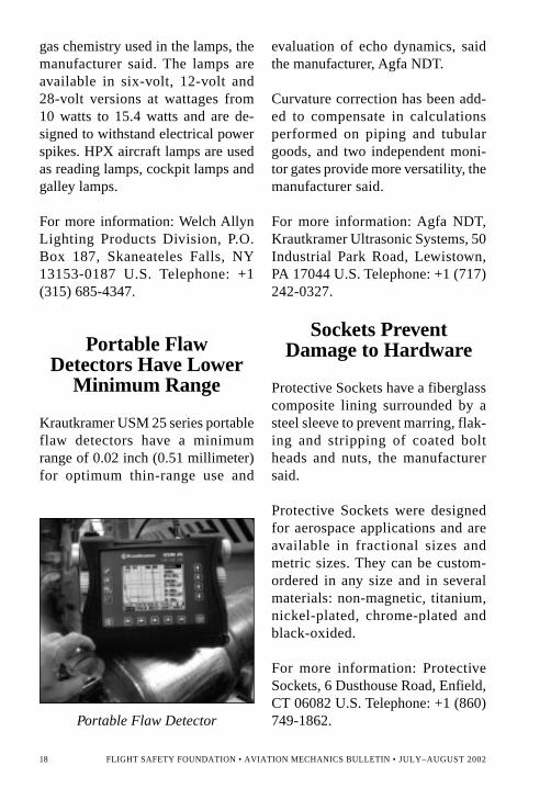
Krautkramer USM 25 series portableflaw detectors have a minimumrange of 0.02 inch (0.51 millimeter)for optimum thin-range use and
evaluation of echo dynamics, saidthe manufacturer, Agfa NDT.
Curvature correction has been add-ed to compensate in calculationsperformed on piping and tubulargoods, and two independent moni-tor gates provide more versatility, themanufacturer said.
For more information: Agfa NDT,Krautkramer Ultrasonic Systems, 50Industrial Park Road, Lewistown,PA 17044 U.S. Telephone: +1 (717)242-0327.
Sockets PreventDamage to Hardware
Protective Sockets have a fiberglasscomposite lining surrounded by asteel sleeve to prevent marring, flak-ing and stripping of coated boltheads and nuts, the manufacturersaid.
Protective Sockets were designedfor aerospace applications and areavailable in fractional sizes andmetric sizes. They can be custom-ordered in any size and in severalmaterials: non-magnetic, titanium,nickel-plated, chrome-plated andblack-oxided.
For more information: ProtectiveSockets, 6 Dusthouse Road, Enfield,CT 06082 U.S. Telephone: +1 (860)749-1862.Portable Flaw Detector

FLIGHT SAFETY FOUNDATION • AVIATION MECHANICS BULLETIN • JULY–AUGUST 2002 19
Portable MicroscopeAids in Measuring
Aircraft Skin Cracks
A compact, portable microscopefrom AEI Optics Unlimited providesreal-time, flat-field images for a va-riety of applications, including ob-serving and measuring surfacefinishes and aircraft skin cracks, themanufacturer said.
The Video-Check Roll and the Video-Check Roll-Z produce images at
magnifications from 25 times actualsize to 2,350 times actual size forobservation and long-term storage,the manufacturer said. The focusingbarrels of both microscopes containprogrammable rings to vary illumi-nation effects, and the housing allowsoperators to easily change fixed-magnification objectives. Plastic-covered, non-conductive, silicone-free rollers protect targets againstdamage and unwanted deposits.
For more information: AEI OpticsUnlimited, 2521 Cherry Valley Turn-pike, Marcellus, NY 13108 U.S. Tele-phone: +1 (315) 673-4151.
Adapters FeatureCorrosion-resisting-steel
Band
Raychem CRES-Lock Adapters havea corrosion-resisting-steel (CRES)band that can be installed aroundscreen braid cable to establish anelectrical connection between thebraid and the adapter, said the manu-facturer, Tyco Electronics.
Raychem CRES-Lock Adapters canbe tightened and secured with a buck-le design that allows the band to re-main under tension during thecut-and-lock-in-place operation. Theterminated cable is sealed by a heat-shrinkable covering that increases thestrain relief. Raychem CRES-LockAdapters are available with straightPortable Microscope

20 FLIGHT SAFETY FOUNDATION • AVIATION MECHANICS BULLETIN • JULY–AUGUST 2002
CRES bands or pre-coiled CRESbands and with a variety of options.
For more information: Tyco Elec-tronics, P.O. Box 3608 MS 38-41,Harrisburg, PA 17105-3608 U.S.Telephone: +1 (650) 361-4470.
Battery MonitorFeatures
Large-screen Display
The DataFX monitors aircraftbatteries and battery cells with alarge-screen display for viewing asmany as 22 cell voltages simulta-neously, said the manufacturer, theChristie division of Marathon Pow-er Technologies.
The DataFX works with any aircraftbattery charger/analyzer used inservicing large, vented NiCad batter-ies and lead acid batteries. Afterthe DataFX is connected to the air-craft battery charger/analyzer, it scansa battery’s cells during charge and
discharge to measure cell voltages atvarious intervals and displays theresult on a panel screen. The infor-mation can be transferred to paperwith an optional serial printer.
For more information: MarathonPower Technologies Co., 8301 Impe-rial Drive, Waco, TX 76712 U.S.Telephone: +1 (254) 776-0650.
Assembly-processMonitor Detects
Fastener-related Errors
The TS II Qualifier assembly-processmonitor can be used with electric-powered drivers or air-powered driv-ers to detect fastener-related assemblyerrors, said the manufacturer, theASG Division of Jergens.
The assembly-process monitor candetermine whether each screw in anassembly has been inserted, torquedto its designated value, cross-threadedor stripped. The assembly-processmonitor also can be programmed tostop the assembly process if a pre-setparameter is not achieved, can moni-tor the assembly process to determinewhether washers or gaskets have beenomitted from a fastener and can beprogrammed for use with automaticfeeders.
For more information: ASG, 15700 S.Waterloo Road, Cleveland, OH 44110U.S. Telephone: +1 (216) 486-6163.♦Battery Monitor


Want more information about Flight Safety Foundation?
Contact Ann Hill, director, membership and development,by e-mail: [email protected] or by telephone: +1 (703) 739-6700, ext. 105.
Visit our Internet site at <www.flightsafety.org>.
Submit your nomination(s) via our Internet site.Go to http://www.flightsafety.org/ramp_safety.html
For more information, contact Kim Granados, membership manager,by e-mail: [email protected] or by telephone: +1 (703) 739-6700, ext. 126.
VtÄ Ä y É Ü
aÉÅ|Çt à | ÉÇ áA I R B P R A M P S A F E T Y A W A R D
Established by Air BP and first presented in 1996, this award recognizesoutstanding or significant improvement in the ramp environment throughinnovation and implementation of a ramp safety program. Recipientshave been honored for their efforts in such areas as prevention ofground-damage accidents, improvement of aircraft rescue and firefighting services and reduction of injuries among baggage handlers.
The award includes travel to the Flight Safety Foundation InternationalAir Safety Seminar (IASS) for the award presentation and a handsome,wood-framed, hand-lettered citation. The award is administered bythe Foundation.�The nominating deadline is Aug. 30, 2002.
Flight Safety Foundation


![Electronic Communications Act - Life Healthcare · ELECTRONIC COMMUNICATIONS AND TRANSACTIONS ACT 25 OF 2002 [ASSENTED TO 31 JULY 2002] [DATE OF COMMENCEMENT: 30 AUGUST 2002] ...](https://static.fdocuments.us/doc/165x107/5e5628de22435a641055dec7/electronic-communications-act-life-healthcare-electronic-communications-and-transactions.jpg)
![July, August 2002 [Find the Missing Peace]](https://static.fdocuments.us/doc/165x107/55cf9c62550346d033a9a92a/july-august-2002-find-the-missing-peace.jpg)