JSC 29353B Flammability Configuration Analysis for ... · JSC 29353B Flammability Configuration...
54
JSC 29353B Flammability Configuration Analysis for Spacecraft Applications July 2014 National Aeronautics and Space Administration Lyndon B. Johnson Space Center Houston. Texas https://ntrs.nasa.gov/search.jsp?R=20150020937 2018-06-05T03:26:19+00:00Z
Transcript of JSC 29353B Flammability Configuration Analysis for ... · JSC 29353B Flammability Configuration...
JSC 29353B
Flammability Configuration Analysis for Spacecraft Applications
July 2014
National Aeronautics and Space Administration Lyndon B. Johnson Space Center Houston. Texas
https://ntrs.nasa.gov/search.jsp?R=20150020937 2018-06-05T03:26:19+00:00Z

Preface
This document was prepared to assist International Space Station, and other program hardware customers with the flammability configuration analyses required to justify the use of flammable materials in flight hardware. The document provides guidance in conducting the flammability assessments required for payload hardware by SSP 51700, "Payload Safety Policy and Requirements for the International Space Station". It may also be used to assess flammability hazards in flight hardware other than payloads, as described in NASA-STD--6001B, Flammability, Offgassing, and Compatibility Requirements and Test Procedures and NASA-STD--6016, Standard Materials and Processes Requirements for Spacecraft. It explains procedures and techniques that are considered by NASA to meet the intent of the safety requirements, but it does not preclude alternative approaches.

Flammability Configuration Analysis for Spacecraft Applications Prepared By: ES4 / Michael D. Pedley _____________________ GFE Materials Control Lead Approved By: ES4 / Rachel Kamenetzky
_____________________ Chief, Materials and Processes Branch
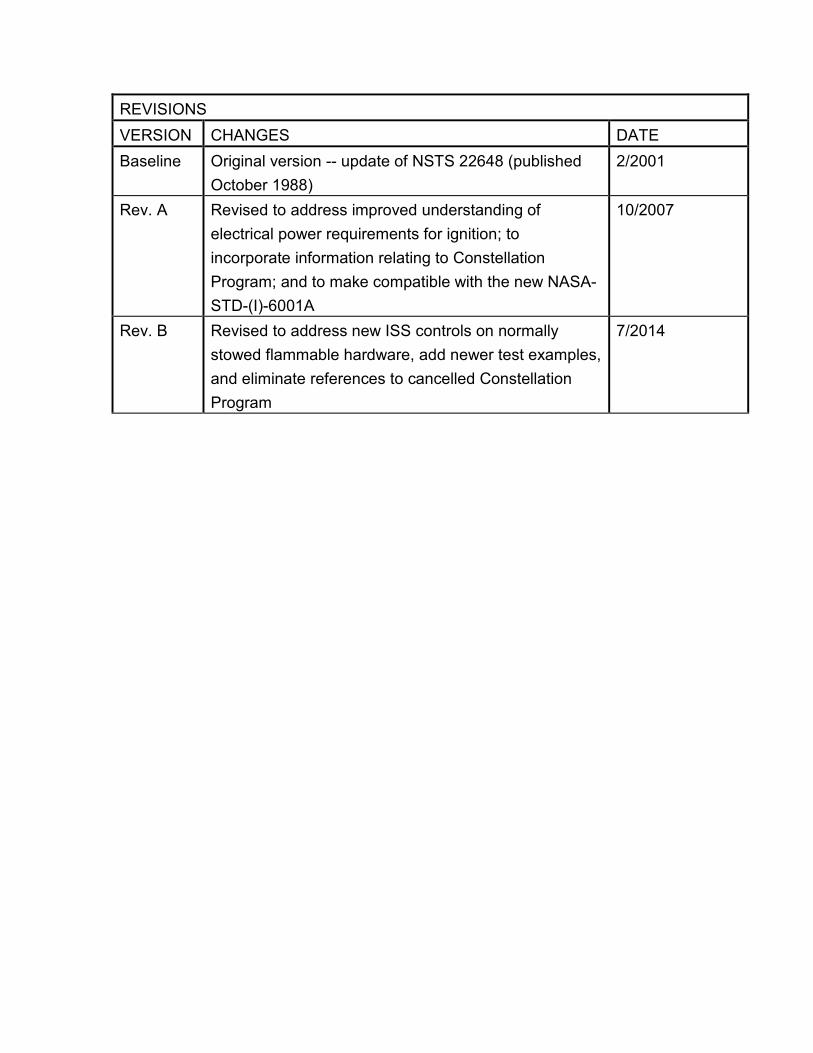
REVISIONS
VERSION CHANGES DATE
Baseline Original version -- update of NSTS 22648 (published
October 1988)
2/2001
Rev. A Revised to address improved understanding of
electrical power requirements for ignition; to
incorporate information relating to Constellation
Program; and to make compatible with the new NASA-
STD-(I)-6001A
10/2007
Rev. B Revised to address new ISS controls on normally
stowed flammable hardware, add newer test examples,
and eliminate references to cancelled Constellation
Program
7/2014
Table of Contents Page 1.0 INTRODUCTION 1 2.0 TECHNICAL REQUIREMENTS 1 2.1 NASA-STD-6001 1 2.2 SSP51700 2 2.3 SSP 30233 2 2.4 NASA-STD-6016 3 3.0 ENVIRONMENTS 3 4.0 FLAMMABILITY ASSESSMENT GUIDELINES 5 4.1 Evaluate the overall hardware configuration 5 4.2 Evaluate the way in which the hardware will be used 6 4.3 Identify the major materials to be assessed 6 4.4 Determine fire propagation paths 9 4.5 Evaluate ability of container to contain fire 9 5.0 CONTAINERS 9 5.1 Sealed Containers 9 5.2 Vented Containers 10 5.3 Intermediate Containers 11 6.0 STOWED HARDWARE 11 7.0 FLAMMABILITY REDUCTION METHODS 13 7.1 General Materials Protection 13 7.2 Wire and Cable 14 7.3 Electrical Connectors 16 7.4 Tubes and Hoses 16 7.5 Hook and Loop Fasteners 16 7.6 Stowage Bags and Lockers 17 7.7 Thermal Control Blankets 18 7.8 Composites and Fiber-Reinforced Laminates 19 8.0 TEST EXAMPLES 19 8.1 Materials Selection 19 8.2 Aluminum Tape Overwrap 20 8.3 Nomex® Sleeve Covering 20

Table of Contents (continued) Page 8.4 Sealed Containers 20 8.5 Vented Containers 26 8.6 Intermediate Containers 33 8.7 Special Cases 38

Figures
Figure Page 1 Flammability Assessment Logic Diagram 8 2. Bluetooth Speakers 21 3 Battery-powered screwdriver 22 4 Disposable Dish Rack Overwrapped with 3-mil Aluminum Tape 23
5 Flammable Hose Protected by Natural Nomex HT-9040 24
6 Wet Wipe Dispenser (Double-Layer Natural Nomex HT-9040) 25 7 Apollo Master Events Sequence Controller 27 8 Space Shuttle Inertial Measurement Unit 28 9 Space Shuttle Proximity Switch Box 29 10 Typical Aluminum Electronics Box for Airflow Tests 31 11 Damaged Aluminum Vent Screen from Airflow Tests 31 12 ISS Power Inverter Flammability Test 32 13 Simulated MPCV Avionics Box Flammability Test 34 14 Apollo Entry Monitor System 35 15 Apollo Rotational Controller 36 16 Camcorder, External View (Internal Ignition, Post-Test) 37 17 Camcorder, External View (External Ignition, Post-Test) 37 18 ISS Vacuum Cleaner Cable Flammability Test 40

Appendices Appendix Page Appendix A -- Test References A-1 Appendix B -- Specification References B-1 Appendix C -- Definitions C-1 Appendix D -- Acronyms and Abbreviations D-1 Appendix E -- Flammability Rationale Codes E-1

JSC 29353B Page 1
1.0 INTRODUCTION Fire is one of the many potentially catastrophic hazards associated with the operation of crewed spacecraft. A major lesson learned by NASA from the Apollo 204 fire in 1966 was that ignition sources in an electrically powered vehicle should and can be minimized, but can never be eliminated completely. For this reason, spacecraft fire control is based on minimizing potential ignition sources and eliminating materials that can propagate fire. Fire extinguishers are always provided on crewed spacecraft, but are not considered as part of the fire control process. “Eliminating materials that can propagate fire” does not mean eliminating all flammable materials – the cost of designing and building spacecraft using only nonflammable materials is extraordinary and unnecessary. It means controlling the quantity and configuration of such materials to eliminate potential fire propagation paths and thus ensure that any fire would be small, localized, and isolated, and would self-extinguish without harm to the crew. Over the years, NASA has developed many solutions for controlling the configuration of flammable materials (and potentially flammable materials in commercial “off-the-shelf” hardware) so that they can be used safely in air and oxygen-enriched environments in crewed spacecraft. This document describes and explains these design solutions so payload customers and other organizations can use them in designing safe and cost-effective flight hardware. Proper application of these guidelines will produce acceptable flammability configurations for hardware located in any compartment of the International Space Station or other program crewed vehicles and habitats. However, use of these guidelines does not exempt hardware organizations of the responsibility for safety of the hardware under their control. 2.0 TECHNICAL REQUIREMENTS 2.1 NASA-STD-6001 NASA-STD-6001, "Flammability, Offgassing, and Compatibility Requirements and Test Procedures" describes material flammability tests and requires a system flammability evaluation for materials that fail those tests. All flight hardware used in NASA crewed space programs must either comply with the flammability testing requirements of NASA-STD-6001 or be assessed to prohibit fire propagation based on the (presumed flammable) hardware design or configuration. This alternative analytical approach is widely used for off-the-shelf hardware and electronic equipment and is discussed in subsequent sections of this document.

JSC 29353B Page 2
Note: NASA-STD-6001 contains several required material flammability tests:
Test 1 – Upward Flame Propagation Test 4 – Electrical Wire Insulation Flammability Test 17 – Upward Flammability of Materials in GOX Test 18 – Arc Tracking
It also contains several supplemental tests such as A.2.4, Configurational Flammability (Test 10)1, that may be used, as needed, for further evaluation of materials that fail the basic tests or for testing special hardware configurations. For general-purpose solid materials used in vehicle crew compartments, the fundamental flammability test is Test 1 (or a special configurational variation on Test 1). Test 4 and Test 18 (which is not a true flammability test) are used only for electrical wire insulation in power circuits. The other tests are not required for payloads or any other flight program. Test 17 applies only to pressurized oxygen systems (Test 1 or Test 17 can be used for pressures up to 50 psia). The most recent revision of NASA-STD-6001, NASA-STD-6001B, was released in August 2011. This release of JSC 29353 is compatible with NASA-STD-6001B and earlier versions of NASA-STD-6001. 2.2 SSP 51700 All ISS payloads are required to meet the flammability requirements in SSP 51700, "Payload Safety Policy and Requirements for the International Space Station" paragraph 3.10.2.2 SSP 51700 tailors the NASA-STD-6001 requirements by exempting materials used in small quantities (less than 0.1 lb. or 10 square inches in crew environments and less than 1 lb. and/or 12 linear inches for external materials). SSP 51700 also requires a flammability assessment in accordance with the guidelines of this document.3 2.3 SSP 30233 International Space Station vehicle hardware is required to comply with SSP 30233, Space Station Requirements for Materials and Processes. SSP 30233
1 Test 10, formerly titled Simulated Panel or Major Assembly Flammability Test, was made a
supplemental test in NASA-STD-6001B. 2 Some older payloads may be required to meet NSTS 1700.7B, "Safety Policy and Requirements
for Payloads Using the Space Transportation System,“ paragraph 209.2 and the identical requirements in the NSTS 1700.7B ISS Addendum. However, the flammability requirements are the same as in SSP 51700. 3 SSP 51700 currently states that guidelines for the conduct of flammability assessments are
provided in NSTS 22648, Flammability Configuration Analysis for Spacecraft Applications. JSC 29353 is intended as a replacement for NSTS 22648 with clearer and more current guidance.
JSC 29353B Page 3
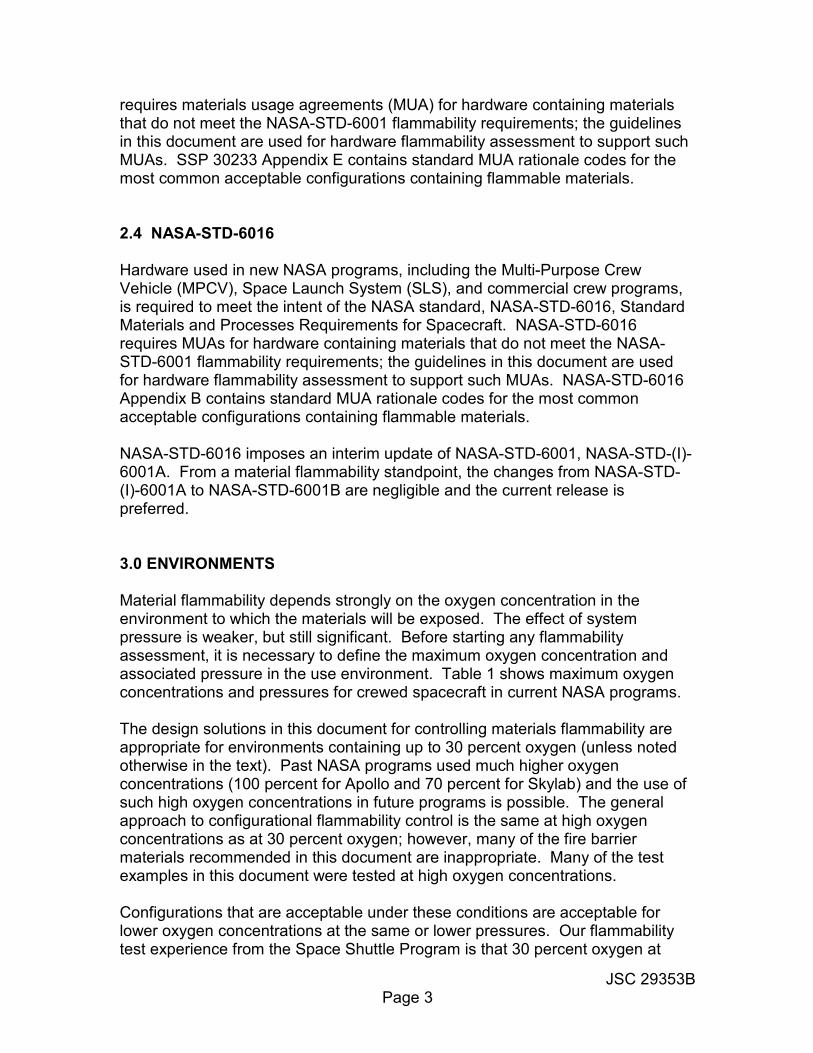
requires materials usage agreements (MUA) for hardware containing materials that do not meet the NASA-STD-6001 flammability requirements; the guidelines in this document are used for hardware flammability assessment to support such MUAs. SSP 30233 Appendix E contains standard MUA rationale codes for the most common acceptable configurations containing flammable materials. 2.4 NASA-STD-6016 Hardware used in new NASA programs, including the Multi-Purpose Crew Vehicle (MPCV), Space Launch System (SLS), and commercial crew programs, is required to meet the intent of the NASA standard, NASA-STD-6016, Standard Materials and Processes Requirements for Spacecraft. NASA-STD-6016 requires MUAs for hardware containing materials that do not meet the NASA-STD-6001 flammability requirements; the guidelines in this document are used for hardware flammability assessment to support such MUAs. NASA-STD-6016 Appendix B contains standard MUA rationale codes for the most common acceptable configurations containing flammable materials. NASA-STD-6016 imposes an interim update of NASA-STD-6001, NASA-STD-(I)-6001A. From a material flammability standpoint, the changes from NASA-STD-(I)-6001A to NASA-STD-6001B are negligible and the current release is preferred. 3.0 ENVIRONMENTS Material flammability depends strongly on the oxygen concentration in the environment to which the materials will be exposed. The effect of system pressure is weaker, but still significant. Before starting any flammability assessment, it is necessary to define the maximum oxygen concentration and associated pressure in the use environment. Table 1 shows maximum oxygen concentrations and pressures for crewed spacecraft in current NASA programs. The design solutions in this document for controlling materials flammability are appropriate for environments containing up to 30 percent oxygen (unless noted otherwise in the text). Past NASA programs used much higher oxygen concentrations (100 percent for Apollo and 70 percent for Skylab) and the use of such high oxygen concentrations in future programs is possible. The general approach to configurational flammability control is the same at high oxygen concentrations as at 30 percent oxygen; however, many of the fire barrier materials recommended in this document are inappropriate. Many of the test examples in this document were tested at high oxygen concentrations. Configurations that are acceptable under these conditions are acceptable for lower oxygen concentrations at the same or lower pressures. Our flammability test experience from the Space Shuttle Program is that 30 percent oxygen at
JSC 29353B Page 4
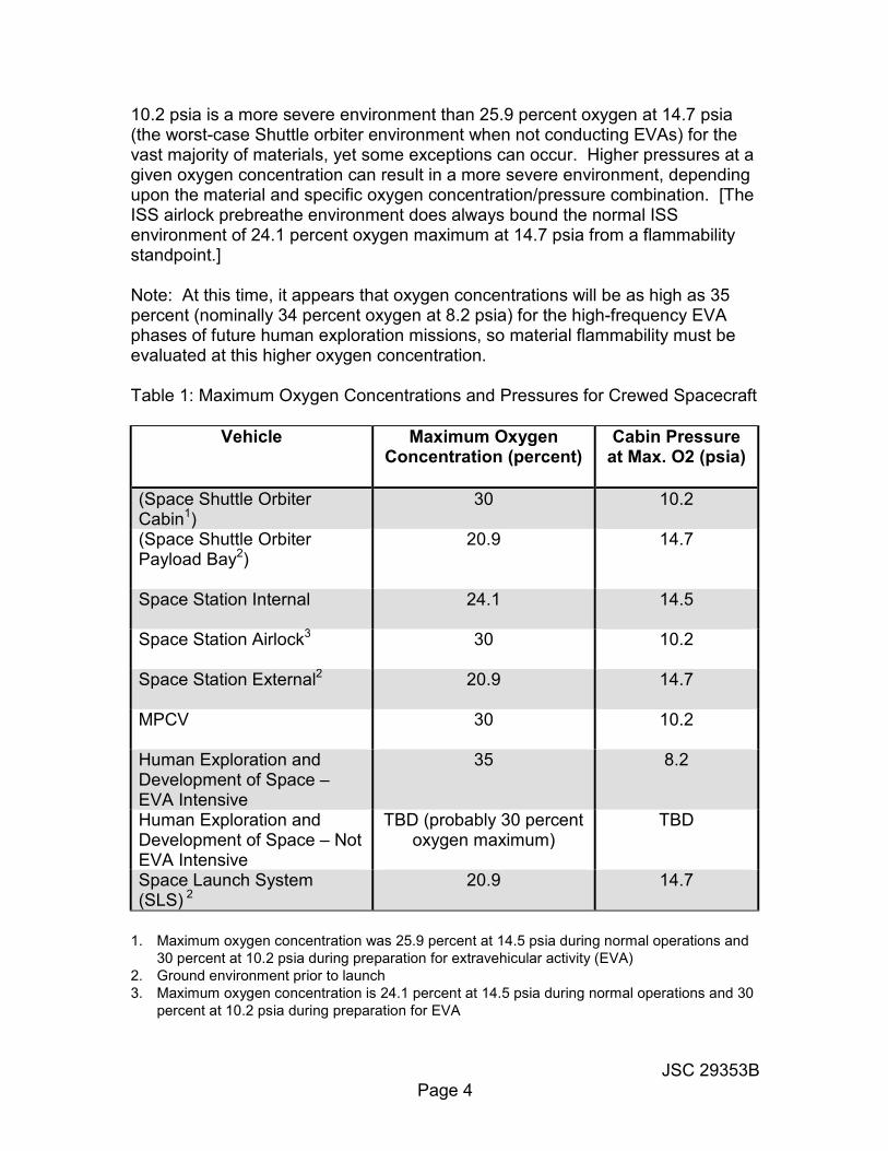
10.2 psia is a more severe environment than 25.9 percent oxygen at 14.7 psia (the worst-case Shuttle orbiter environment when not conducting EVAs) for the vast majority of materials, yet some exceptions can occur. Higher pressures at a given oxygen concentration can result in a more severe environment, depending upon the material and specific oxygen concentration/pressure combination. [The ISS airlock prebreathe environment does always bound the normal ISS environment of 24.1 percent oxygen maximum at 14.7 psia from a flammability standpoint.] Note: At this time, it appears that oxygen concentrations will be as high as 35 percent (nominally 34 percent oxygen at 8.2 psia) for the high-frequency EVA phases of future human exploration missions, so material flammability must be evaluated at this higher oxygen concentration.
Table 1: Maximum Oxygen Concentrations and Pressures for Crewed Spacecraft
Vehicle Maximum Oxygen Concentration (percent)
Cabin Pressure at Max. O2 (psia)
(Space Shuttle Orbiter Cabin1)
30 10.2
(Space Shuttle Orbiter Payload Bay2)
20.9 14.7
Space Station Internal 24.1 14.5
Space Station Airlock3
30 10.2
Space Station External2 20.9 14.7
MPCV
30 10.2
Human Exploration and Development of Space – EVA Intensive
35 8.2
Human Exploration and Development of Space – Not EVA Intensive
TBD (probably 30 percent oxygen maximum)
TBD
Space Launch System (SLS) 2
20.9 14.7
1. Maximum oxygen concentration was 25.9 percent at 14.5 psia during normal operations and
30 percent at 10.2 psia during preparation for extravehicular activity (EVA)
2. Ground environment prior to launch
3. Maximum oxygen concentration is 24.1 percent at 14.5 psia during normal operations and 30
percent at 10.2 psia during preparation for EVA

JSC 29353B Page 5
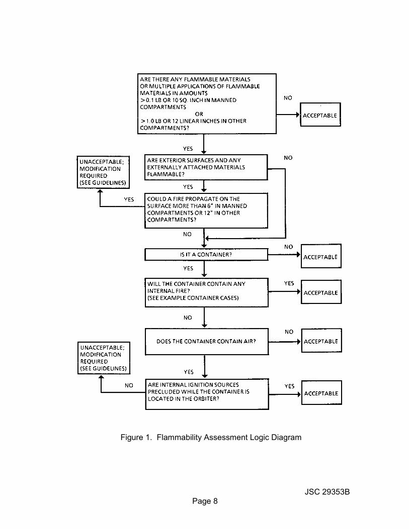
4.0 FLAMMABILITY ASSESSMENT GUIDELINES The following guidelines provide assessment procedures that allow users to evaluate flammability hazards associated with their equipment. Users can employ these guidelines as a similarity basis for certifying their hardware. For ISS payloads, an explanation of this assessment process and its results must be included in the hazard report. When a flammability assessment results in an unacceptable configuration, reduction of flammability hazards is necessary to correct the flammability problems. The primary methods used by NASA to reduce flammability hazards are the limitation of flammable materials by replacement with nonflammable materials and the restriction of propagation paths, either by covering flammable materials with a nonflammable material or by separation of flammable materials. When the results of the flammability configuration analysis are inconclusive, the hardware configuration (or a simulated configuration with acceptable fidelity) may be tested for flammability to determine acceptability. The hardware organization should contact the appropriate NASA materials organization to determine what testing is required. Alternatively, the hardware organization may choose to assume the configuration is flammable and implement appropriate measures to eliminate the flammability hazard. To conduct a flammability configuration assessment, the following procedures should be used. A top level flammability assessment logic diagram is shown in Figure 1. 4.1 Evaluate the overall hardware configuration. Flight hardware is often in the form of a “black box”, a container with internal electronics, experiments, etc. Such containers are frequently very effective at containing internal fires. Sealed containers have no vent openings and a verified maximum leak rate. Vented containers have active vents and associated cooling airflow. Intermediate containers have no active vents or cooling airflow, but are not physically sealed to prevent air exchange; many commercial off-the-shelf electronics items fall into this intermediate category.
• If the hardware is a closed box without vents or power, the materials inside the box will not contribute to the fire hazard unless the box is constructed from flammable materials – the box acts as a fire barrier.
• If the only electrical power within the box is from alkaline batteries, the maximum short-circuit power draw is nearly always too low to act as an ignition source. Recent NASA testing has shown that solid materials in an atmosphere containing 34 percent oxygen at 15 psia cannot be ignited by

JSC 29353B Page 6
electrical powers of around 25 watts1. Typical low-voltage dry batteries (alkaline, NiCad, lithium-ion, lithium) are incapable of delivering powers approaching this value, although larger batteries (such as lithium-ion rechargeable batteries associated with power tools) might.
Guidelines for assessing the ability of containers to contain internal fires are provided in Section 5.0. 4.2 Evaluate the way in which the hardware will be used Hardware that is normally stowed in a fireproof container and exposed to the cabin environment for short periods during use may be acceptably controlled by compliance with stowage constraints (Section 6.0). Fireproof containers provided by NASA include all stowage lockers and essentially all stowage bags, such as the ISS cargo transfer bags (CTB).
• A full flammability analysis is required for hardware that is permanently mounted in a rack or a locker space
4.3 Identify the major materials to be assessed
• Amounts greater than 0.1 pounds (or 6 linear inches maximum dimension and/or 10 square inches maximum area) in crew-habitable compartments.
• Amounts greater than 1.0 pounds (or 12 linear inches) in other compartments
• Metallic panels and structures are nonflammable in environments containing 30 percent oxygen or less (even magnesium and titanium) and need not be considered. Metallic screens may be flammable and must be addressed.
• Inorganic materials (ceramics) are also nonflammable in environments containing 30% percent oxygen or less and need not be considered.
• Adhesives (sandwiched between two surfaces) and materials covered or overcoated by nonflammable materials need not be considered.
The flammability characteristics of these materials can be determined by consulting the NASA George C. Marshall Space Flight Center (MSFC) Materials and Processes Technical Information System (MAPTIS) database. The MAPTIS materials selection database is available on line at http://maptis.nasa.gov.
1 Excluding materials with a finely divided flock on the surface, such as moleskin and some
medical dressings, none of which are used in powered boxes.
JSC 29353B Page 7
Access to other areas of MAPTIS requires registration using the MAPTIS Request Form located on this page. When using MAPTIS to obtain flammability characteristics, the MAPTIS rating must be matched to the use application. An A-rating in MAPTIS for test conditions approximately the same as the use conditions means the material is acceptable in unlimited quantities; any other rating means the material quantity/exposure must be controlled. The following key factors in material flammability must be considered when using MAPTIS flammability data:
• Oxygen concentration – The importance of oxygen concentration has already been noted. If MAPTIS flammability data obtained at higher oxygen concentrations show that a material is acceptable, it is generally acceptable at lower concentrations. Thus, an A-rated material at 30 percent oxygen is almost always acceptable for use at lower oxygen concentrations. However, since even small increases in oxygen concentration can change the flammability rating, a material that is acceptable in 24.1 percent oxygen may be flammable in 24.5 percent oxygen.
• Note: Hardware designed for internal or external use on ISS is acceptable for transport in pressurized areas of the vehicles with higher oxygen concentrations, provided it is unpowered and stowed in a locker or nonflammable stowage bag such as a CTB. Unpowered metal boxes (which may be painted) are also acceptable. Hardware not meeting these constraints must be assessed for flammability at the higher oxygen concentration.
• Pressure -- Ambient pressure usually has a much smaller effect on flammability than oxygen concentration but it shouldn’t be ignored. At a given oxygen concentration, higher pressures are generally more flammable than lower pressures. Relatively large changes in pressure are generally required to alter a material’s flammability rating. However, the effects are material-dependent and should be evaluated1.
• Material thickness – flammability varies with material thickness, so the thickness associated with the MAPTIS rating should be approximately the same as the use thickness. In general, flammability decreases with increasing thickness, so a material is usually acceptable if a thinner version of the same material is A-rated for flammability. However, exceptions do occur, so the hardware organization must document such extrapolations in the flammability assessment.
1 “Pressure Effects on the Extinguishment Limits of Aerospace Materials,” David B. Hirsch, James
H. Williams, Jon P. Haas, Harold D. Beeson, Gary A. Ruff, and Michael D. Pedley, 39th International Conference on Environmental Systems, 12-16 July, 2009, Savannah, Georgia, 09ICES-0267.
JSC 29353B Page 8
Figure 1. Flammability Assessment Logic Diagram
JSC 29353B Page 9
• Coatings on substrates – Thin coatings bonded to or sprayed on metallic substrates are generally not flammable because the substrate acts as a heat sink. Most MAPTIS coating flammability data were obtained using 6-mil or 20-mil aluminum substrates. Coating flammability always decreases with increasing substrate thickness, so a coating on a metallic substrate is acceptable if it is A-rated for flammability on a thinner substrate. If no data exist, but the coating is less than 2 mils thick and the metal substrate is at least 20 mils thick, the coating is acceptable. However, nonmetallic substrates are not effective heat sinks, so flammability data obtained using metallic substrates are not applicable; in such cases, the specific configuration may need to be tested for flammability.
4.4 Determine fire propagation paths Determine whether the externally exposed materials (including container housings) represent fire propagation paths exceeding 6 inches in crew habitable compartments or 12 inches in other areas. For any given material application, propagation from one flammable material application to the next is not acceptable and should be precluded. Fire propagation paths can be limited by fire breaks. If fire propagation is possible, positive action must be taken to control or eliminate the hazard. Sample solutions are included in Sections 6 and 7 of this document. 5.0 CONTAINERS The fire containment capability of containers must be evaluated according to the amount of fuel involved, container wall characteristics, and the presence of a combustion-supporting environment. 5.1 Sealed Containers Hermetically sealed containers have a verified, extremely low leak rate and may be filled with an inert gas such as nitrogen. Environmentally sealed containers also have a verified low leak rate (higher than hermetically sealed containers); they normally contain air. NASA-STD-6001 defines sealed containers as having a helium leak rate less than 1 x 10⁻⁴ cm3/second. Fire propagation in a sealed container depends upon the container structural configuration. If the sealed container does not contain oxygen or contains an inert gas, then it can be assumed that fire will not be initiated. Further, it may be assumed that for sealed metal containers with an air (or other spacecraft atmosphere similar to those in Table 1) environment, fire will be contained if the container wall is at least 60 mils thick. The same would also apply to nonmetallic

JSC 29353B Page 10
containers, provided the container materials are nonflammable and are not melted away by an internal fire. For the much higher oxygen concentrations during the Apollo and Skylab programs, the internal void space was also a significant factor and generally limited to less than 30 percent of the total volume. However, for Space Station and expected Human Exploration and Development of Space applications, a larger void space is acceptable and the normal (tight) packing of flight electronics limits the internal void space acceptably. 5.2 Vented Containers Because oxygen is available to vented containers, it cannot be assumed that the container will contain a fire. However, tests have shown that it is possible for vented containers to contain fires if the container vents are covered with a fine metal (non-aluminum) screen or if the vent area is less than 1 percent of the total surface area. For other vented container configurations, conditions that would lead to uncontrolled fires (such as airflow, vent type, and vent location) must be addressed. For hardware that is not powered while mated to or installed in the spacecraft, internal ignition sources are generally excluded from containers. Therefore, fire initiation is unlikely, and this fact can be the basis for acceptability. However, long-term ground-based power testing must not present a significant fire hazard. The fire containment capability of vented containers must be carefully evaluated, because these containers allow replenishment of oxygen to support combustion of flammable materials. Definition of acceptable vented container configurations is very difficult, even with qualifications. In general, minimizing the number and size of vents and covering such vents with fine metal screens (using fire-resistant metals, such as stainless steel or nickel, rather than relatively flammable metals, such as aluminum, titanium, or magnesium) can reduce this hazard. Minimizing the free volume inside the container by adding nonflammable packaging materials, such as polyimide foam, can also help. The forced airflow velocity is also a major factor in the combustion of materials inside vented containers. If forced air flow is not required, it is desirable from a flammability standpoint to cover all vents and assess the hardware as an intermediate container1. However, if forced airflow is present, the relation between flow rate and flammability is complex. At low flow rates, flammable internal materials burn more vigorously with increasing flow rate (thus decreasing the effectiveness of the container). At very high flow rates, the airflow will prevent maintenance of stable flames, thus “blowing out” the fire. The intermediate flow
1 External factors may prevent this. For example, the MPCV crew module must be depressurized
for some EVA activities, so containers must be vented to relieve the internal pressure.
JSC 29353B Page 11
rates represent the worst case; however, the worst-case flow rate is very configuration-dependent and may also be affected by the microgravity conditions on orbit. Thus, it is essentially impossible to determine by analysis the acceptable flow rates for a specific vented container configuration. 5.3 Intermediate Containers As noted above, the intermediate container, which is not airtight but has no active vents or airflow, is a very common configuration in ISS. Examples include avionics boxes that are cold-plate cooled but not sealed (and may have covered vents for pressure equalization), NASA-provided stowage lockers and stowage bags, and most commercial electronics items that do not contain a cooling fan. NASA-provided stowage lockers and stowage bags can be treated as containers that act as barriers to external fire1. Flammable materials stowed in these containers do not constitute a fire risk while in the containers, provided they are unpowered. However, powered payloads/experiments that are stowed in lockers for an entire mission (or are located in place of a locker) present a potential fire hazard and must be evaluated as such. Many commercial electronics items can be addressed through the stowage constraints described in Section 6.0. However, items that do not comply with the stowage constraints may be acceptable if the case can be shown to be nonflammable and capable of containing an internal fire. Many electronic items can be obtained commercially in metallic or nonflammable polycarbonate cases and the internal components are inevitably packed sufficiently closely that void space is not a concern. In addition, many small, commercial items are powered internally by alkaline or lithium-ion batteries. Even in a hard short situation, such batteries are incapable of delivering sufficient energy to ignite solid, flammable materials (see 4.1). Although we cannot completely eliminate potential ignition sources in spacecraft on a vehicle scale, we can conclude that internal ignition is impossible for such battery-powered components. Thus, the only potential for ignition is from external ignition sources – and can be eliminated by a nonflammable case or by covering the case with a nonflammable material (see below). 6.0 STOWED HARDWARE Many small, commercial, off-the-shelf components are used in a spacecraft. Examples include cameras; power tools; compact and digital video discs, mp3 players, and tablet computers; medical devices and medications; clothing; and
1 Stowage lockers and stowage bags for the MPCV crew module are not yet fully designed, but
they will have vent areas small enough that they can still be treated as intermediate containers.

JSC 29353B Page 12
personal hygiene items. Most items of this type are stowed in lockers or nonflammable stowage bags, are taken out only as required, and are returned after use. The NASA Johnson Space Center provides the majority of this hardware for ISS as Government-Furnished Equipment (and expects to do the same for the future crewed programs). JSC has determined that such stowed hardware is acceptable for flammability (regardless of the flammability of the hardware materials), provided it meets at least one of the following constraints:
• Maximum dimension 10 inches, and unstowed less than 1 day/week
• Unstowed less than 1 hour/day
• Maximum dimension less than 6 inches, and always stowed when not in actual use
• Used only when covered by crew clothing
• Exposed surface area less than 1 square foot, and always worn by crew when unstowed.
Ensuring that these stowage constraints are met would require specific flight rules for each hardware item controlled by stowage, which is an unreasonable imposition on crew operations. During the Space Shuttle Program, NASA relied on crew housekeeping, which was sufficient to ensure that flammable items were returned to stowage after use. However, the same approach was not effective for ISS, because the much larger pressurized volume allowed for many unstowed items to be left out indefinitely (generally attached to walls with hook-and-loop fasteners). In response, ISS developed a generic Operational Control Agreement Database (OCAD) for control of flammable items on ISS. At the time of writing, this OCAD is currently OCAD 101882; however, OCAD numbers do change occasionally, independent of any changes to the content. The text of OCAD 101882 reads:
• When not in use, flammable items will be stowed in non-flammable stowage containers or compartments.
• Non-flammable stowage containers include: CTBs, JSBs, other bags or containers made of non-flammable material, ZSR/RSR compartments, and designated stowage areas in payload or other racks.
• When deployed in the open cabin for use, flammable items will be kept away from rack power outlets, utility outlet panels (UOPs) and power strips (a.k.a. Junction boxes).
JSC 29353B Page 13
• A guideline of approximately 6” between the flammable item and power sources will be provided in crew training. Measurement in real time is not required.
This operational control applies to the list of items below. This list is not all inclusive.
• Plastic or Trash Bags (Ziplocs, waste bags, food packaging, etc.)
• Fabric and Foam (clothing, towels, Velcro, foam packing material, etc.)
• Off-the-shelf plastics (camcorders, mp3 players, inflatable globe, etc.) (not laptops)
• Paper (procedure books, wipes, reading materials, pictures, post-its, etc.)
• Bungees Hardware organizations may use the controls in OCAD 101882 (or any current flight successor) as rationale for accepting stowed, flammable hardware (or stowed hardware of unknown flammability) for use on ISS, provided the use of this OCAD is properly documented in a materials certification, an MUA, or a payload flammability assessment. Hardware that meets the dimension/unstowed time constraints listed in this section and is used in compliance with OCAD 101882 will always be acceptable. Hardware items that do not meet the constraints normally require additional design/operational mitigations to control flammability while unstowed. In some cases, payloads require unique operational controls to mitigate flammability; such controls would be documented in a payload-unique OCAD. 7.0 FLAMMABILITY REDUCTION METHODS This section describes common methods used to control flammability hazards. These methods include replacement of flammable materials with nonflammable alternatives and various methods of protecting flammable materials by covering them with nonflammable materials. 7.1 General Materials Protection Commercial items with flammable outer surfaces (such as acrylonitrile butadiene styrene (ABS), polyvinyl chloride (PVC), polyethylene, and/or polyamides (nylons)) may be wrapped completely with a nonflammable tape. 3-mil aluminum tape (such as Federal Specification L-T-80) will protect most plastics, foam, and cardboard from external flame initiation. If aluminum tape cannot be used for electrical reasons, a nonflammable fiberglass tape with a silicone or acrylic adhesive will give the same protection. However, when an item is wrapped with

JSC 29353B Page 14
fiberglass tape, each rotation should overlap the previous one by 50 percent for acceptable flammability protection. Other nonflammable tape materials may be acceptable. For long-term applications, where tape is aesthetically unacceptable but fire protection is needed, the flammable surfaces may be coated with a nonflammable barrier material, such as a fluoroelastomer. NASA has used fluoroelastomer coatings reasonably successfully for several years; fluoroelastomer-coated hardware looks much better than taped hardware, but the coating process is expensive and complex and the coating durability is only fair. The original coating for this application was Fluorel® (hexafluoropropene and vinylidene fluoride copolymer) mill stock; Fluorel® mill stock is no longer available but other fluoroelastomer mill stock materials such as DAPCO 2030® have been used instead. The most common nonmetallic case materials for commercial items used in space flight (such as cameras, camcorders, CD players and laptop computers) are ABS, which is extremely flammable, and polycarbonates, which are normally acceptable at oxygen concentrations up to 30 percent. Polycarbonate/ABS blends are also seen quite often; they are acceptable for use in ISS environments up to 24.1 percent oxygen. In many cases, the hardware organization may be able to select a commercial item with a metallic or polycarbonate case, thus eliminating the need for wrapping or coating with a nonflammable material. Electrically powered items with internal flammable materials can usually be treated as fire-resistant containers. In some cases, even a highly flammable case is an adequate fire barrier against propagation of an internal fire to the outside of the container. As a last resort, an item may be filled with a suitable material (such as a nonflammable glass-filled-epoxy potting compound) to provide acceptable flammability protection from internal ignition sources; cases where this approach is needed are extremely rare. 7.2 Wire and Cable Most aerospace-grade electrical wire insulation is nonflammable in ISS and human exploration environments. Limitations are usually driven by other factors, such as flexibility and cut-through resistance.
• Teflon (SAE-AS-22759 (formerly MIL-W-22759), ANSI/NEMA-WC-27500 (formerly MIL-C-27500), or equivalent) – good general-purpose wire; high flexibility but poor cut-through resistance
• Polyimide – no longer used except in flat circuits, because of propensity to arc track

JSC 29353B Page 15
• Teflon-Polyimide Hybrids (SAE-AS-22759, ANSI/NEMA-WC-27500, or equivalent) – good general-purpose wire; lower flexibility than Teflon, but higher cut-through resistance
• Tefzel (SAE-AS-22759, ANSI/NEMA-WC-27500, or equivalent) – suitable for external applications but flammable in enriched oxygen; performance similar to hybrids
ISS also uses a custom silicone-insulated construction in power circuits (SSQ 21652). This construction is nonflammable in ISS environments and exceptionally flexible. Electrical wiring found in commercial off-the-shelf hardware typically has PVC, polyethylene, or chloroprene insulation. These insulation materials are flammable in ISS/human exploration enriched oxygen environments and their use is generally discouraged (PVC-insulated wiring is usually nonflammable in air). They may be used only when demonstrated to be acceptable in configuration by a flammability configuration analysis. Commercial wiring inside electronics boxes and low-power signal wiring outside such boxes can usually be accepted by this method; however, external power cables nearly always need to be replaced or protected from ignition. Flammable insulation is acceptable on wires in external payloads that are not powered (including during ground testing) until the payload is in a vacuum where it will not burn. Methods for protecting flammable cables include:
• Covering with a braided Teflon sleeve, such as Goretex sleeving
• Wrapping the cable with FEP Teflon tape (the simplest and most common approach – used widely for protecting commercial cables such as USB cables used on ISS)
• Wrapping with a nonflammable fiberglass-backed-silicone adhesive tape
• Covering with a sleeve of 7.2 oz/yd2 natural Nomex HT-9040® fabric, Beta cloth, polybenzimidazole (PBl), or other nonflammable fabrics
• Covering by heat shrinking a polyvinylidene fluoride or Teflon sleeve onto the cable
However, it should be noted that these flammable materials are not really suitable for spacecraft power cables and protective covers may unacceptably affect the usability of signal cables for items such as earphones and headsets. Wire and cable accessories such as cable markers, spacers, and cable ties should not contribute to fire propagation paths. Polyvinylidene fluoride or

JSC 29353B Page 16
fluoroelastomeric cable markers are generally used. Other types of cable marker material may be acceptable if used in small discrete amounts or covered with a clear Teflon TFE or FEP sleeve. Most types of spacers are usually acceptable because of their heat sink effects. Acceptable lacing cords can be made from Teflon TFE, Teflon TFE/fiberglass, or Nomex, and acceptable cable ties can be made from ETFE or ECTFE fluoropolymers. When flammable cable tie wraps are used on nonflammable cables, they should be spaced at least 2 inches apart to prevent fire propagation. 7.3 Electrical Connectors In air and moderately-enriched oxygen environments (up to 40 percent oxygen), the shell of a metal shell connector prevents fire propagation from the nonmetallic materials used inside the connector to other nonmetallic materials, regardless of the material inside the connector. Therefore, the configuration is always acceptable for flammability and testing is not required. A flammability configuration analysis is required for nonmetallic shell connectors. The acceptability of the nonmetallic materials used inside the connector depends on the flammability of the shell material and its ability to act as a fire barrier. 7.4 Tubes and Hoses External tubes or hoses (such as a vacuum cleaner hose) made from flammable materials may be replaced with a nonflammable material or covered with a fire barrier material. Clear TFE or FEP Teflon tubes and hoses are readily available to replace flammable materials. If flammable tubes or hoses must be used, the exterior can be protected by a covering of 7.2 oz/yd2 natural Nomex HT-9040®, PBI, Beta cloth, or other nonflammable fabric. In such cases, the potential for ignition of the tube walls from the inside must be addressed. Tubing and hoses used in medical experiments are usually flammable and cannot be replaced or covered without compromising the experiment. Such hardware can usually be accepted as complying with the stowage guidelines in Section 6. 7.5 Hook and Loop Fasteners Although some hook-and-loop fastener materials are less flammable than others, all common types of hook and loop fasteners are flammable in spacecraft habitable areas. To prevent long flame propagation paths, the following usage

JSC 29353B Page 17
limits are generally applied to hook and loop fasteners in habitable areas1:
• Maximum size: 4 square inches, individually or in pieces
• Maximum length: 4 inches
• Minimum separation distance: 2 inches in any direction from another piece With these controls, flammability is not a factor in selection of hook-and-loop fastener materials. NASA normally uses nylon hook-and-loop fasteners in habitable areas, because of their significantly greater durability than hook-and-loop fasteners made from other materials. Nomex® hook-and-loop fasteners are commonly used for EVA operations, because they have good low-temperature performance. Several brands of both have been qualified for flight. 7.6 Stowage Bags and Lockers Metal stowage lockers that do not contain ignition sources are acceptable without reservation. Material selection criteria for nonmetallic stowage lockers must be based on fire containment capability and should be supported by test data. Acceptable stowage bags may be constructed from the following fabrics:
• Beta cloth
• Natural Nomex HT-9040® of weight at least 7.2 ounces/square yard
• PBI
• Other flame-retardant fabrics The following are examples of acceptable stowage bags: Beta cloth bags -- a bag made of Beta cloth is acceptable for stowage of potentially flammable materials. The disadvantages of Beta cloth are its low durability and a tendency to shed glass fibers. However, Beta cloth is nonflammable at very high oxygen concentrations. Nomex® bags -- Bags made of natural Nomex HT-9040® fabric are acceptable for oxygen concentrations up to 30 percent and are widely used in ISS. Lighter weights of natural Nomex® are acceptable in double layers. Other forms of Nomex® may be acceptable, but their flammability must be verified through MAPTIS or by test. Some of these forms have been used extensively for ISS, but
1 These usage limits have been demonstrated acceptable in atmospheres up to 30 percent
oxygen but have not yet been tested for the higher oxygen concentrations expected for EVA-intensive Human Exploration and Development of Space operations.

JSC 29353B Page 18
availability is sometimes an issue (the ISS second-generation redesigned CTBs were made from Combo® Nomex® but the manufacturer ceased production shortly after). Navy blue single-layer Nomex® weighing 6.5 ounces/square yard and treated with ammonia dihydrogen phosphate fire retardant was used extensively on the Space Shuttle; however, its use is discouraged for ISS, because the fabric cannot be wiped down without removing the fire retardant. These containers, made of nonflammable nonmetallic materials, can have flammable items stowed inside them provided they do not contain ignition sources (such as electrical power) and are not susceptible to spontaneous ignition or chemical reaction. Note: Most stowage bags and lockers contain foam assemblies as part of the packaging. The most common foam packaging materials, polyurethane and polyethylene foams are highly flammable. These materials are acceptable if they stay inside the container, no ignition sources are present, and the container is opened only briefly. If the container may be left open for significant periods or the foam is likely to be taken out of the container, it should be covered with a single layer of natural Nomex HT-9040®; the Nomex® is commonly used even when fire protection is not required, because it facilitates insertion and removal of hardware. A commercially-available Kynar foam, Zotek F30®, is nonflammable up to 45 percent oxygen and can be used in place of polyurethane and polyethylene foams without any need for the operational constraints or the Nomex® coating. 7.7 Thermal Control Blankets Thermal control blankets are the most widely used potentially flammable external materials. These blankets typically contain 12 to 40 layers of film (0.0005 to 0.002 inches in thickness) separated by some type of scrim cloth. Blanket materials are usually constructed of metal-coated polyethylene terephthalate or polyimide film with an organic separator scrim. For durability, the inner and outer layers are generally heavier than the internal layers. The outer layer has controlled optical properties and is usually polyimide, silver-Teflon, or Beta cloth. Acceptable thermal control blankets are typically constructed as follows: a. The outer layer is made of nonflammable material such as polyimide film (at
least 1.5 mil thick), silver-Teflon, or Beta cloth. b. Internal layers can be a combination of flammable films or scrims. c. Edges are hemmed or suitably finished so that the inner flammable layers
are protected
JSC 29353B Page 19
For long-term exposure to low-earth-orbit environments, erosion of outer surfaces by atomic oxygen must also be considered. 7.8 Composites and Fiber-Reinforced Laminates Graphite-epoxy composite structures are generally nonflammable in atmospheres up to the ISS 24.1 percent oxygen but marginal for flammability in spacecraft atmospheres containing 30 percent oxygen and above. For spacecraft atmospheres containing above 24.1 percent oxygen, they should be protected or their flammability characteristics verified by test. Bismaleimide-based carbon composites have not been widely tested, but the bismaleimide resin is similar to polyimides so they are likely to be nonflammable in all environments listed in Table 1. Fiber-reinforced laminates can be more flammable than graphite-based composites. The flammability characteristics of thin laminates should be verified by test, or the laminates should be protected. Flammable laminates may be used in external payloads, provided that ignition sources (electrical wires, heaters, etc.) are not located within 6 inches of the laminates. Otherwise, firebreaks should be placed on the exposed surfaces of these laminates at 12-inch intervals. Aluminum tape 3 mils thick and 3 inches wide (per Federal Specification L-T-80) is an acceptable fire break when applied to the laminate surface at 12-inch intervals. 8.0 TEST EXAMPLES The following test examples show some design solutions for protecting flammable materials that have been demonstrated by test. These examples, together with the guidelines in earlier sections, can be used to assess the fire risk of other configurations. Most hardware configurations can be assessed by similarity without the need for testing. 8.1 Materials Selection The ISS Program initially selected a portable mini Bluetooth speaker system with an ABS case. Since this speaker system is expected to be left out in the ISS vehicle for long periods, flammability cannot be adequately controlled through stowage. The Bluetooth speaker burned completely when tested for flammability in 24.1 percent oxygen at 14.7 psia (see test reference 1). A comparable Bluetooth speaker from another manufacturer has an aluminum case and was undamaged and still operated after flammability testing in similar conditions (see test reference 2). Figure 2 shows the Bluetooth speaker with the ABS case before and after test and the Bluetooth speaker with the aluminum case after test.

JSC 29353B Page 20
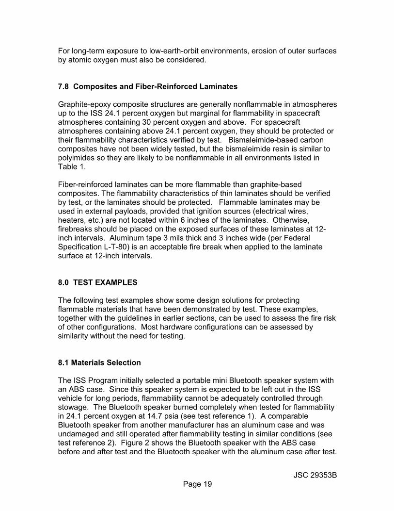
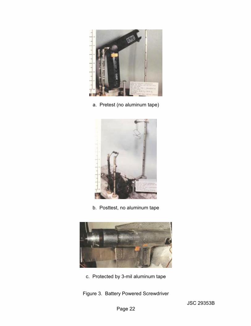
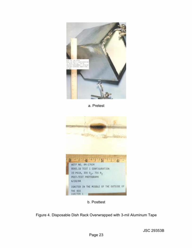
Note: These results should not be interpreted as suggesting either Bluetooth speaker is superior for general purpose use on the ground. Flammability is not a real discriminator when selecting such items for ground use – only in the specialized spacecraft environment. 8.2 Aluminum Tape Overwrap A battery powered screwdriver was tested to demonstrate the effectiveness of 3-mil aluminum tape as a fire barrier in 30 percent oxygen at 10.0 psia (see test reference 3). The plastic-cased screwdriver burned completely when tested unprotected, but was unaffected when tested wrapped with the tape. Figure 3 shows the pretest and post-test conditions of the screwdriver with and without tape protection. NASA also tested a disposable dish rack with a cardboard outer case overwrapped with 3-mil aluminum tape (see test reference 4). Only the area near the igniter was scorched; the rest of the container was unaffected. Figure 4 shows the pretest and post-test conditions of the dish rack. 8.3 Nomex® Sleeve Covering A flammable silicone rubber vacuum cleaner hose was covered with a sleeve of double-layer natural Nomex HT-9040® and tested for flammability at 25.9 percent oxygen (see test reference 5). This sleeve provided the hose with enough protection so that only a small area of the Nomex® sleeve was scorched. Figure 5 shows the pretest and post-test conditions of the hose. A single layer of Nomex HT-9040® would provide an acceptable fire barrier for this application. NASA has also tested double-layer natural Nomex HT-9040® bags. The wet wipe dispenser is made of double-layer Nomex® and is normally filled with wet wipes. When tested at 25.9 percent oxygen at 14.3 psia, flame scorched the area surrounding the igniter. Figure 6 shows the pretest and post-test conditions of this bag (see test reference 6). 8.4 Sealed Containers A few tests have been conducted on internal ignition of inert-gas-filled sealed containers. The ignition source was internal electrical wiring, electrically overloaded until the wire insulation fused (the standard NASA-STD-6001 igniter was not used, because it does not burn in the absence of oxygen). As expected, (see test reference 7 for an example), even when highly flammable materials were present inside the container, nothing ignited and the only damage was from the electrical overload.

JSC 29353B Page 21
(a) ABS speaker pretest (b) ABS Speaker posttest
(c) Aluminum speaker posttest
Figure 2. Bluetooth Speakers
JSC 29353B Page 22
a. Pretest (no aluminum tape)
b. Posttest, no aluminum tape
c. Protected by 3-mil aluminum tape
Figure 3. Battery Powered Screwdriver
JSC 29353B Page 23
a. Pretest
b. Posttest
Figure 4. Disposable Dish Rack Overwrapped with 3-mil Aluminum Tape
JSC 29353B Page 24
a. Pretest
b. Posttest
Figure 5. Flammable Hose Protected by Natural Nomex HT-9040

JSC 29353B Page 25
a. Pretest
b. Posttest
Figure 6. Wet Wipe Dispenser (Double-Layer Natural Nomex HT-9040)

JSC 29353B Page 26
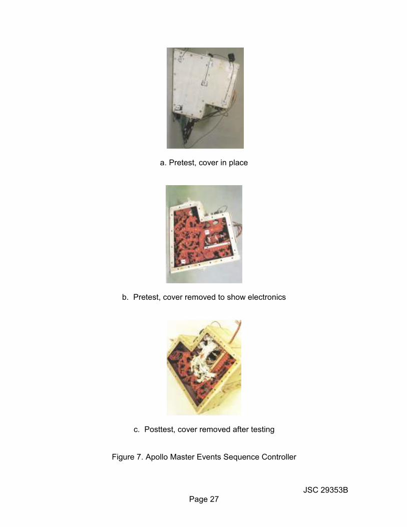
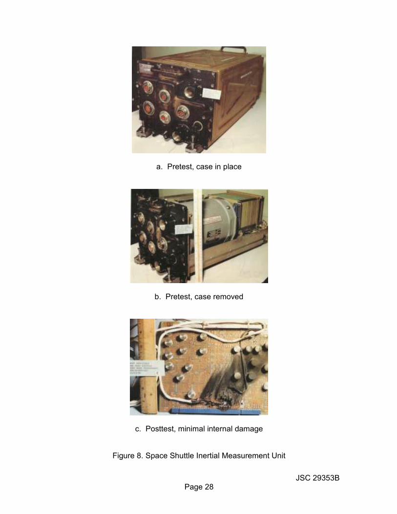
Several tests have been conducted on sealed containers that were not filled with inert gases. An example is the Apollo program master events sequence controller. This item was tested with an internal atmosphere of 100 percent oxygen at 16 psia, using a standard NASA-STD-6001 igniter (see test reference 8). Although all internal polymeric materials were flammable in this atmosphere, the resultant fire was contained with minor internal damage from local surface burning of the room-temperature vulcanizing silicone rubber coating on the circuitry and components (Figure 7). The container internal void space for this test was approximately 30 percent. One hundred percent oxygen at 16 psia is a far more demanding environment than for Space Station and human exploration of space. 8.5 Vented Containers The Space Shuttle inertial measurement unit was a formed aluminum box containing polyurethane-coated circuit boards, chloroprene vent hoses, MIL-W-810441 polyalkene-insulated wire, and about 20 percent void space. The polyurethane coating, chloroprene hoses, and polyalkene-insulated wire are all flammable. The inertial measurement unit was tested for internal flammability in 25.9 percent oxygen at 14.3 psia and in 30 percent oxygen at 10.0 psia at its normal cooling flow rate of 6.3 standard cubic feet per minute (scfm) (see test reference 9). The unit passed both flammability tests with minimal damage. Figure 8 shows the pretest and post-test conditions of this unit. A proximity switch box constructed of sheet metal was also tested (see test reference 10). This box contained electrical components, polyurethane-coated circuit boards, and 50 percent void space. Flammability tests were conducted with a gas flow rate of 1.1 scfm in 25.9 percent oxygen at 14.3 psia, and in 30 percent oxygen at 10.0 psia. This unit also passed both flammability tests with minimal damage. Figure 9 shows the pretest and post-test conditions of this unit. An additional series of tests was conducted to evaluate the effects of air flow and air flow rates on the flammability of worst-case items contained in typical electronic boxes (see test references 11 and 12). These tests were performed in 30 percent oxygen at 10.0 psia, using relatively high flow rates of 6.5 to 20.0 scfm. The boxes were constructed of sheet metal and the following internal materials, all of which are highly flammable in this atmosphere: Polyurethane packing foam
• Plastic sheet, laminated, copper-clad GE uncoated circuit boards
1 MIL-W-81044 has been replaced by SAE-AS-81044 but the Shuttle wiring was purchased to the
original military specification.
JSC 29353B Page 27
a. Pretest, cover in place
b. Pretest, cover removed to show electronics
c. Posttest, cover removed after testing
Figure 7. Apollo Master Events Sequence Controller
JSC 29353B Page 28
a. Pretest, case in place
b. Pretest, case removed
c. Posttest, minimal internal damage
Figure 8. Space Shuttle Inertial Measurement Unit

JSC 29353B Page 29
a. External view, pretest
b. Internal view, pretest
c. Internal view, case removed after test
Figure 9. Space Shuttle Proximity Switch Box
JSC 29353B Page 30
• MIL-W-81044 polyalkene-insulated electrical wire. Figure 10 shows a typical electronic box used in this type of testing. Testing was conducted using standard NASA-STD-6001 igniters. Although the internal materials ignited and burned readily in these tests, the fire was contained in the boxes in all cases except one. In this one test, conducted at a flow rate of 15 scfm, the polyurethane foam burned sufficiently vigorously to ignite the large (6-inch diameter) aluminum vent screen and fire escaped outside the box (see Figure 11). Additional tests on the same box configuration demonstrated containment of the fire at lower and higher air velocities (10 scfm and below; 20 scfm and above). At velocities below 10 scfm and above 20 scfm, the unit is an effective container; however, at intermediate velocities, it is not. These results illustrate the difficulty of generalizing the effects of flow velocity on the ability of vented containers to contain fires. The vent in this test was very large (although corresponding to only about 1 percent of the total surface area) and the aluminum screen was only partially consumed. Despite the high flammability of the internal materials, all fires would have been contained if a more fire-resistant material than aluminum had been used (such as stainless steel or nickel). The aluminum screen is a poor choice from a flammability standpoint, but would probably have survived if it had been significantly smaller. A far more recent example of a vented container test is the testing conducted on the power inverter for ISS. The power inverter units flown on ISS are an off-the-shelf design that takes standard ISS direct current (DC) power (120 volts or 28 volts DC) and converts it to standard household 110 volts alternating current (AC) so that commercial off-the-shelf electrical hardware can be powered directly. The flight units have a custom metallic case with additional 110 volt outlets but the unmodified commercial unit also has a metallic case and was used for flammability testing. The inverter is air-cooled; the cooling fan was powered during the flammability testing but the inverter electronics were not. The internal materials were unidentified but assumed to be flammable in the test environment of 24.1 percent oxygen at 14.7 psia. Inverter flammability testing was conducted with the standard flammability test igniter located so the igniter flame would impinge on likely flammable materials (see test reference 13). Three tests were conducted with no sign of ignition beyond the igniter (in an initial test, the igniter itself failed to ignite because the air flow from the cooling fan continuously “blew it out”; the igniter had to be relocated outside the direct air flow to maintain a flame). Figure 12 shows the inverter prior to test and the inverter interior after the three flammability tests; damage is barely detectable (the igniter can be seen in its final location).

JSC 29353B Page 31
Figure 10. Typical Aluminum Electronics Box for Airflow Tests
Figure 11. Damaged Aluminum Vent Screen from Airflow Tests

JSC 29353B Page 32
a. External view, pretest
b. Internal view, case removed after test
Figure 12. ISS Power Inverter Flammability Test

JSC 29353B Page 33
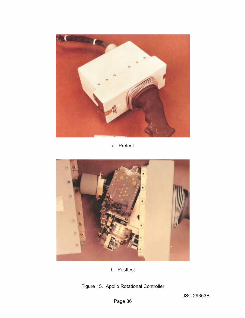
8.6 Intermediate Containers Simulated MPCV avionics boxes were tested in an environment of 40 percent oxygen at 14.7 psia to demonstrate that fire suppression capability was not required because any internal fire would self-extinguish even at a much higher oxygen concentration than the worst-case MPCV environment of 30 percent oxygen at 10.2 psia (see test reference 14). The simulated boxes were fabricated from 6061 aluminum, thickness less than 0.1 inches, and with Gore® Protective Adhesive Vents for pressure equalization Figure 13a). Initial tests were conducted with electronic circuitry and polyurethane foam inside the box; the ribbon cable and foam ignited but self-extinguished within about 30 seconds without anything other than smoke propagating outside the box (Figure 13b). The test was repeated with nothing inside the box except polyurethane foam and free volumes inside the box of 60 and 80 percent; in both cases, the polyurethane foam ignited but self-extinguished with relatively little material consumed (Figure 13c). This testing demonstrates that it is essentially impossible to propagate a fire outside a nonflammable container when there is no forced convection for atmosphere exchange. The Apollo entry monitor system and the Apollo rotational controller assembly were tested in 100 percent oxygen at 6.2 and 16.5 psia (see test references 15 and 16). The entry monitor system is a metal box containing circuit boards, a power supply, etc. When ignited, it burned for over 4 minutes and reached a
peak internal temperature of 1250 °F. The rotational controller assembly is a hand controller-type device (with a silicone rubber boot over the handle opening to form a dust seal) containing polyurethane-coated circuit boards. When ignited,
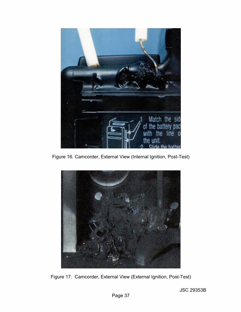
this unit burned for 3 minutes and reached an internal temperature of 1280 °F. However, both of these units contained the resulting fire. Figure 14 shows the pretest and post-test conditions of the entry monitor system and Figure 15 shows the pretest and post-test conditions of the rotational controller assembly. A more recent example of the effectiveness of such unsealed containers is the camcorders flown on the Space Shuttle. Essentially all commercial off-the-shelf camcorders have an ABS case. ABS is flammable in air and burns vigorously in enriched oxygen. However, internal ignition testing of a camcorder in 30 percent oxygen at 10.2 psia, using a standard NASA-STD-6001 igniter, showed that the case did not ignite and contained the fire (see test reference 17). The only damage to the case was some sagging where it was partially melted by the flame (Figure 16). A major contributor to the containment of the fire was the very tight packing of the components inside the case. This result is a notable exception to the statement in the previous version of this document that “Obviously, if a container has walls made of flammable materials it cannot serve this purpose and should be evaluated according to the guidelinesR”

JSC 29353B Page 34
a. Pretest (Gore® vents on front face)
b. Posttest (burned internal electronics and foam)
c. Posttest (burned foam -- 80% free volume, 20% foam)
Figure 13. Simulated MPCV Avionics Box Flammability Test

JSC 29353B Page 35
a. Pretest (cover removed)
b. Posttest, cover removed after test
Figure 14. Apollo Entry Monitor System
JSC 29353B Page 36
a. Pretest
b. Posttest
Figure 15. Apollo Rotational Controller
JSC 29353B Page 37
Figure 16. Camcorder, External View (Internal Ignition, Post-Test)
Figure 17. Camcorder, External View (External Ignition, Post-Test)

JSC 29353B Page 38
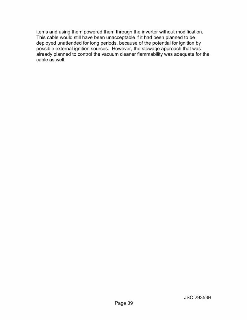
When the same camcorder was tested with the igniter external to and impinging on the case, it burned vigorously and was effectively destroyed (Figure 17). However, the addition of a 4-mil fluoroelastomer coating to the exterior of the case has been shown to protect it from external ignition. Commercial off-the-shelf camcorders with ABS cases and this protective coating were flown routinely on the Space Shuttle from the early 1990s.
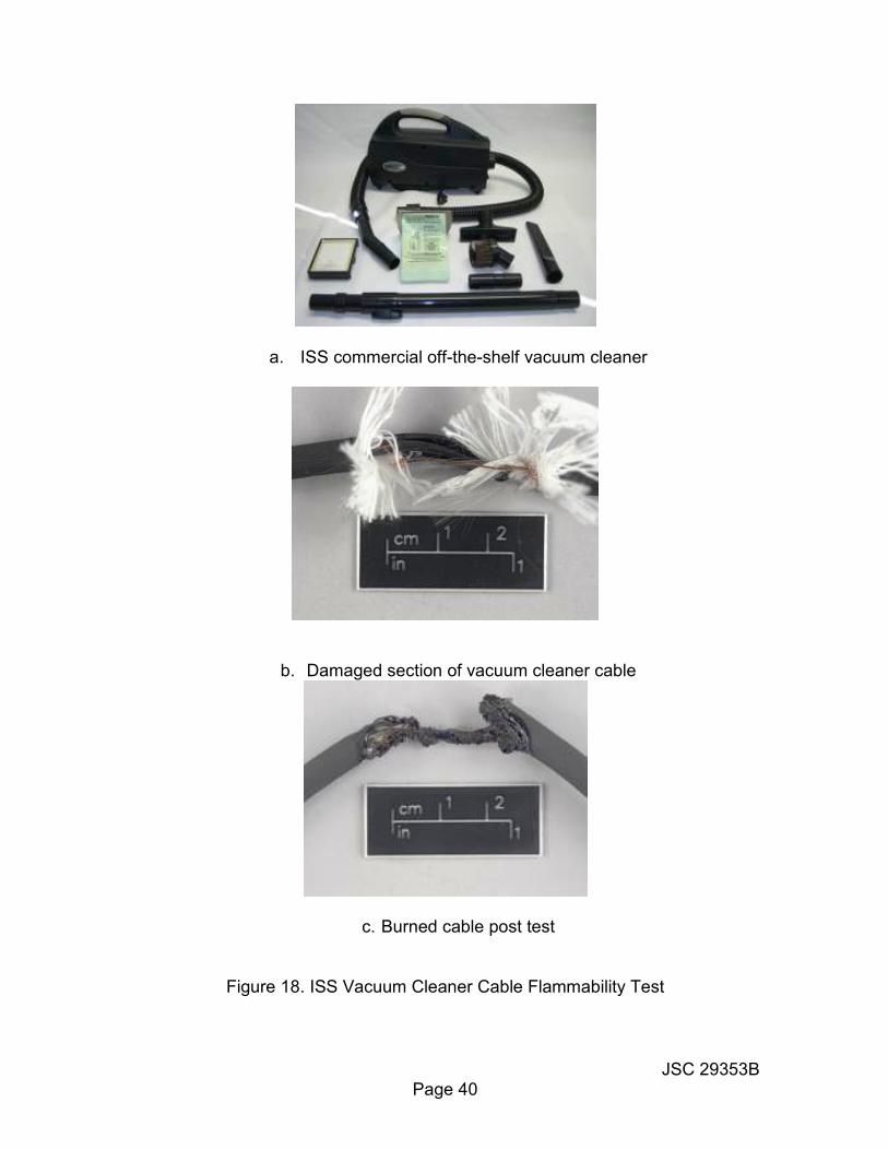
Note: For most payload applications, uncoated camcorders can be controlled for flammability through stowage (Section 5.0). The fluoroelastomer coating is required only for applications where camcorders are mounted in the crew areas and powered by the vehicle power supply for extended periods. Flammability testing of individual camcorders is not necessary, provided the design is similar to previously flown units. 8.7 Special Cases When a hardware design doesn’t fit any of the examples given above, it may still be possible to clear the hardware through a carefully designed unique test program. An example is the testing that was conducted for the ISS commercial off-the-shelf vacuum cleaner power cable, intended to plug into the ISS power inverter. The vacuum cleaner itself (Figure 18a) is constructed of flammable materials but considered acceptable, because it has no credible internal ignition sources, is always tended by the crew while in use, and is always stowed away in a nonflammable container when not in use. However, the power cable is a standard household vacuum cleaner cable with PVC wire insulation wrapped in cotton, and all inside a PVC jacket (an intentionally damaged section of cable is shown in Figure 18b). Although this construction is designed to be nonflammable in air, it is certainly flammable in the ISS enriched oxygen environment and damaged wiring is common for such household vacuum cleaner cables. Since a high current passes through the cable with serious potential to act as an ignition source, this cable was considered to be a significant potential fire risk.
Because of this concern, a test program was conducted to determine whether ignition could occur as a result of an electrical short between damaged vacuum cleaner cable wires. The testing showed that such ignition could occur (Figure 18c), but only with cable damage so severe that it would have been detected long before it reached the point where it could cause ignition (see test reference 18). The configuration in Figure 18b, which resulted in ignition, had significant lengths of bare conductors with frayed cotton looped into intimate contact with the conductors at the location of the short. The test confirmed the expectations that ignition could occur, but the scenario was so extreme as to not be credible and the cable was accepted without modification. Replacing the cable with a nonflammable cable would have been a significant cost impact and would have severely impacted the intended ISS approach of minimizing hardware certification costs by purchasing commercial off-the-shelf
JSC 29353B Page 39
items and using them powered them through the inverter without modification. This cable would still have been unacceptable if it had been planned to be deployed unattended for long periods, because of the potential for ignition by possible external ignition sources. However, the stowage approach that was already planned to control the vacuum cleaner flammability was adequate for the cable as well.
JSC 29353B Page 40
a. ISS commercial off-the-shelf vacuum cleaner
b. Damaged section of vacuum cleaner cable
c. Burned cable post test
Figure 18. ISS Vacuum Cleaner Cable Flammability Test

JSC 29353 Page A-1
Appendix A -- Test References 1. WSTF 14-46333, “Charge Bluetooth® Speaker", NASA White Sands Test
Facility. 2. WSTF 14-46338, “Mini Bluetooth® Speaker", NASA White Sands Test Facility.
3. WSTF 85-18799, "EZ502 Cordless Electric Screwdriver", NASA White Sands
Test Facility. 4. WSTF 84-17634, "Disposable Dishrack", NASA White Sands Test Facility. 5. WSTF 79-11018, "WAVA Hose with Nomex Cover", NASA White Sands Test
Facility. 6. WSTF 78-10785, "Wet Wipe Dispenser with Disposable Towelettes', NASA
White Sands Test Facility.
7. ATR 142010A, “Flammability Test, Hermetically Sealed Container, Thrust Vector Servo Amplifier (TVSA)”, North American Rockwell Corporation, Space Division; April 12, 1968.
8. ATR 142009, "Flammability Tests of Vented Container, Master Events
Sequence Controller (MESC)", North American Rockwell Corporation, Space Division; November 27,1967.
9. WSTF 80-13562, "Inertial Measurement Unit (IMU) Flammability Unit", NASA
White Sands Test Facility. 10. WSTF 80-13561, "Proximity Switch Box MC452-0124", NASA White Sands
Test Facility. 11. TR-325-001, "Atmosphere and Ignition Effects on "Typical" Electronic Box and
Contents", NASA White Sands Test Facility, December 14,1984. 12. TR-325-002, "Atmosphere and Ignition Effects on "Typical" Electronic Box and
Contents”, NASA White Sands Test Facility, November 30,1984.
13. WSTF11-45093, Power inverter 120 V dc", NASA White Sands Test Facility.
14. WSTF 13-46248, Flammability Testing on a Simulation Avionics Box 15. ATR 142014, "Flammability Tests of Vented Container, Entry Monitor System
(EMS)', North American Rockwell Corporation, Space Division; November 16, 1967.

JSC 29353 Page A-2
16. ATR 142011, "Flammability Tests of Vented Container, Rotational Controller”, North American Rockwell Corporation, Space Division; January 3, 1968.
17. WSTF 89-22852, "CCD-V9 Camcorder", NASA White Sands Test Facility.
18. WSTF 12-45702, “COTS Vacuum Cleaner Power Cord”, NASA White Sands
Test Facility.
JSC 29353 Page B-1
Appendix B -- Specification References L-T-80 Tape, pressure-sensitive adhesive (aluminum backed) ANSI/NEMA-WC Standard for Aerospace and Industrial Electrical Cable -27500 (formerly MIL-C-27500F, Cable, electrical shielded and
unshielded, aerospace) SAE-AS-22759 Wire, electric, fluoropolymer-insulated, copper or copper
alloy (formerly MIL-W-22759) SAE-AS-81044 Wire, electric, crosslinked polyalkene, crosslinked alkane-
imide polymer, or polyarylene insulated, copper or copper alloy (formerly MIL-W-81044)
JSC 29353 Page C-1
Appendix C -- Definitions Barrier, Fire -- An obstruction (such as a partition) that prohibits or tends to inhibit the propagation of burning. May be internal or external in configuration. Break. Fire -- A gap, opening, or nonflammable material between flammable materials which would prevent propagation of burning. Containers. Sealed -- Containers that are enclosed adequately enough to preclude the replenishment of a combustible atmosphere under conditions of a fire. Containers, Vented -- Containers that are unsealed and permit atmosphere exchange. Containment. Fire -- The situation in which a fire and/or burning particles do not progress, in any manner, beyond the confines of a configuration. Flammable -- A material which fails to meet acceptance criteria when tested according to the requirements of NASA-STD-6001 (i. e., one that will burn more than 6 inches when ignited). Heat Sink -- A structure or panel of high thermal conductivity in intimate contact with a burning material which extracts sufficient heat by conduction to lower the temperature below the ignition point and extinguish burning. An effective heat sink could limit initial ignition. Ignition Source -- A source of heat sufficiently intense and localized to Induce combustion. For flammability considerations, any electrical wire or elevated temperature component is considered an ignition source. Monopropellants, strong oxidizers, bases, etc. must also be considered. Nonflammable -- A material that meets the acceptance criteria when tested according to the requirements of NASA-STD-6001 (i. e., one that self-extinguishes within 6 inches when ignited). Positive Igniters -- lgniters that produce a controlled flame. Propagation Paths -- The paths taken by a flame front external to (or within)an enclosure that represent fire paths between flammable materials. They are not necessarily straight or coplanar. Void Space -- Unoccupied volume in a container
JSC 29353 Page D-1
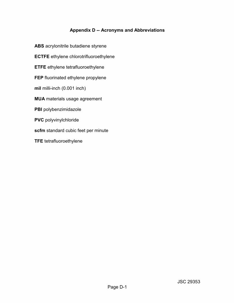
Appendix D -- Acronyms and Abbreviations ABS acrylonitrile butadiene styrene ECTFE ethylene chlorotrifluoroethylene ETFE ethylene tetrafluoroethylene FEP fluorinated ethylene propylene mil milli-inch (0.001 inch) MUA materials usage agreement PBI polybenzimidazole PVC polyvinylchloride scfm standard cubic feet per minute TFE tetrafluoroethylene
JSC 29353 Page E-1
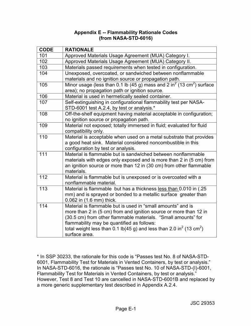
Appendix E -- Flammability Rationale Codes (from NASA-STD-6016)
CODE RATIONALE
101 Approved Materials Usage Agreement (MUA) Category I.
102 Approved Materials Usage Agreement (MUA) Category II.
103 Materials passed requirements when tested in configuration.
104 Unexposed, overcoated, or sandwiched between nonflammable materials and no ignition source or propagation path.
105 Minor usage (less than 0.1 lb (45 g) mass and 2 in2 (13 cm2) surface area); no propagation path or ignition source.
106 Material is used in hermetically sealed container.
107 Self-extinguishing in configurational flammability test per NASA-STD-6001 test A.2.4, by test or analysis.*
108 Off-the-shelf equipment having material acceptable in configuration; no ignition source or propagation path.
109 Material not exposed; totally immersed in fluid; evaluated for fluid compatibility only.
110 Material is acceptable when used on a metal substrate that provides a good heat sink. Material considered noncombustible in this configuration by test or analysis.
111 Material is flammable but is sandwiched between nonflammable materials with edges only exposed and is more than 2 in (5 cm) from an ignition source or more than 12 in (30 cm) from other flammable materials.
112 Material is flammable but is unexposed or is overcoated with a nonflammable material.
113 Material is flammable but has a thickness less than 0.010 in (.25 mm) and is sprayed or bonded to a metallic surface greater than 0.062 in (1.6 mm) thick.
114 Material is flammable but is used in “small amounts” and is more than 2 in (5 cm) from and ignition source or more than 12 in (30.5 cm) from other flammable materials. “Small amounts” for flammability may be quantified as follows: total weight less than 0.1 lb(45 g) and less than 2.0 in2 (13 cm2) surface area.
* In SSP 30233, the rationale for this code is “Passes test No. 8 of NASA-STD-6001, Flammability Test for Materials in Vented Containers, by test or analysis.” In NASA-STD-6016, the rationale is “Passes test No. 10 of NASA-STD-(I)-6001, Flammability Test for Materials in Vented Containers, by test or analysis.” However, Test 8 and Test 10 are cancelled in NASA-STD-6001B and replaced by a more generic supplementary test described in Appendix A.2.4.