Journal of the Magnetics Society of Japan
22
Vol.43 No.1 2019 ISSN 2432-0250 Journal of the Magnetics Society of Japan Electronic Journal URL: https://www.jstage.jst.go.jp/browse/msjmag Spin Electronics Magnetoresistance in Bilayers of Heavy Metal and Non-collinear Antiferromagnet K. Oda, T. Moriyama, and T. Ono …01 Measurement Technique, High-Frequency Devices High Coercivity and Resolution FePt•MgO-coated Tip for Imaging the Magnetic Field of Perpendicular Magnetic Write Head by Alternating Magnetic Force Microscopy (A-MFM) F. Zheng, S. Yoshimura, S. Yasui, G. Egawa, and H. Saito …06 Power Magnetics Evaluation on Edge-supported Magnetic Levitation Apparatus for Thin Steel Plates Y. Oda, Y. Ito, K. Okuno, M. Kida, T. Suzuki, A. Endo, T. Narita, H. Kato and H. Moriyama …11 Journal 広告 ◇東英工業株式会社 ◇計測エンジニアリングシステム株式会社
Transcript of Journal of the Magnetics Society of Japan

Vol.43 No.1 2019
発行(公社)日本磁気学会 〠101‒0052 東
京都千代田区神田小川町2丁目8番地
三井住友海上小川町ビル5階☎(03)5281-0106
印刷(株)国際文献社 〠169‒0075 東
京都新宿区高田馬場3の8の8☎(03)3362-9741
Vol. 39 No. 5 2015 年
9 月 1 日
発行 頒価
¥2,000 (税込)送料実費
ISSN 2432-0250Journal of the Magnetics Society of Japan
Electronic Journal URL: https://www.jstage.jst.go.jp/browse/msjmag
Spin Electronics Magnetoresistance in Bilayers of Heavy Metal and Non-collinear Antiferromagnet
K. Oda, T. Moriyama, and T. Ono …01
Measurement Technique, High-Frequency Devices High Coercivity and Resolution FePt•MgO-coated Tip for Imaging the Magnetic Field of Perpendicular
Magnetic Write Head by Alternating Magnetic Force Microscopy (A-MFM)
F. Zheng, S. Yoshimura, S. Yasui, G. Egawa, and H. Saito …06
Power Magnetics Evaluation on Edge-supported Magnetic Levitation Apparatus for Thin Steel Plates
Y. Oda, Y. Ito, K. Okuno, M. Kida, T. Suzuki, A. Endo, T. Narita, H. Kato and H. Moriyama …11
Journal
広告 ◇東英工業株式会社 ◇計測エンジニアリングシステム株式会社

Electronic Journal: http://www.jstage.jst.go.jp/browse/msjmagHP: http://www.magnetics.jp/ e-mail: [email protected]
43 1 2019

COMSOL, COMSOLロゴ, COMSOL Multiphysics, COMSOL Desktop, COMSOL Server, COMSOL Compiler, LiveLinkはCOMSOL ABの商標または登録商標です。その他の製品名、サービス名、組織名は各組織の商標または登録商標です。
http://www.comsol.jp http://www.kesco.co.jp/comsol/
AC/DCモジュールの適用例
有限要素法解析ソフトウェアCOMSOL Multiphysics®
マルチフィジックスの進化論無制限・強連成で実現象に即したシミュレーション事例のご紹介
永久磁石を使用した磁気軸受永久磁石を使用した軸受はターボ機械、ポンプ、モータ、発電機やフライホイール式エネルギー貯蔵システムなど、様々な分野で使用されています。非接触かつ潤滑不要で保守整備を大幅に省略できる点は、従来の機械式ベアリングと比べて重要なメリットです。この例では、軸方向の永久磁石軸受の磁気力と剛性などの設計パラメータを計算する方法を示しています。※AC/DCモジュールはCOMSOL Multiphysicsと併用するアドオン製品です。
COMSOL Multiphysics®なら、今まで不可能だった 3種以上のマルチフィジックス解析を強連成で実現できます。30日間全機能無料トライアル、無料の導入セミナー、1000種を超える世界の様々な事例をご提供いたします。詳しくは、下記の弊社営業部までお問い合せください。
・インシュレータ、コンデンサ、誘電体・モータ、ジェネレータ、および他の電気機械・非線形材料・寄生容量とインダクタンス・永久磁石と電磁石・多孔質材料・抵抗および誘導加熱・センサ・超伝導体・変圧器とインダクタ
・AC/DC 電流分布、電場分布・バイオヒーティング・コイルとソレノイド・SPICE回路とフィールドシミュレーション・接触抵抗・電磁両立性(EMC)および電磁妨害(EMI)・電磁力およびトルク・電磁力シールド・電気機械の変形・ホール効果を利用したセンサ
永久磁石を利用した磁気軸受の解析例
東京(神田)会場:2019年1月23日13:30-16:30 皆様の拠点へお伺いして開催可能 !お問い合わせください詳細→ https://kesco.co.jp/seminar/1147/
COMSOLご紹介無料セミナー開催 !
INDEX

INDEXINDEX
Journal of the Magnetics Society of JapanVol. 43, No. 1
Electronic Journal URL: https://www.jstage.jst.go.jp/browse/msjmag
CONTENTSSpin Electronics
Magnetoresistance in Bilayers of Heavy Metal and Non-collinear Antiferromagnet
…………………………………………………………………………………K. Oda, T. Moriyama, and T. Ono 1
Measurement Technique, High-Frequency Devices
High Coercivity and Resolution FePt•MgO-coated Tip for Imaging the Magnetic Field of Perpendicular
Magnetic Write Head by Alternating Magnetic Force Microscopy (A-MFM)
……………………………………………………F. Zheng, S. Yoshimura, S. Yasui, G. Egawa, and H. Saito 6
Power Magnetics
Evaluation on Edge-supported Magnetic Levitation Apparatus for Thin Steel Plates
………… Y. Oda, Y. Ito, K. Okuno, M. Kida, T. Suzuki, A. Endo, T. Narita, H. Kato and H. Moriyama 11
Board of Directors of The Magnetics Society of Japan
President: K. Takanashi
Vice Presidents: K. Nakagawa, S. Nakamura
Directors, General Affairs: Y. Miyamoto, K. Niiduma
Directors, Treasurer: K. Aoshima, K. Ishiyama
Directors, Planning: Y. Saito, S. Nakagawa
Directors, Editorial: K. Kobayashi, T. Ono
Directors, Public Relations: H. Itoh, S. Greaves
Directors, International Affairs: Y. Takemura, M. Nakano
Auditors: Y. Suzuki, R. Nakatani

1Journal of the Magnetics Society of Japan Vol.43, No.1, 2019
INDEXINDEX
J. Magn. Soc. Jpn., 43, 1-5 (2019)<Paper>
Magnetoresistance in bilayers of heavy metal and non-collinear antiferromagnet
K. Oda, T. Moriyamaa), and T. Ono
Institute for Chemical Research, Kyoto University, Uji, Kyoto, 611-0011, Japan
We report on magnetoresistance measurements in a heavy metal/ Mn3Ir multilayers. After a post annealing process, we observed the magnetoresistance associated with the ordered crystalline structure of the Mn3Ir. The resistance change as a function of the strength as well as the direction of the applied field suggests that the magnetoresistance is partially related to a modification of the Néel order by the magnetic field. Our further detailed investigation revealed that there is an additional component of the resistance change, perhaps due to the non-collinear magnetic structure associated with the L12-ordered Mn3Ir, which cannot be accounted for by any conventional magnetoresistance effects. a) [email protected] Key words: antiferromagnetic spintronics, anisotropic magnetoresistance, spin Hall magnetoresistance, Mn3Ir, chiral magnetic structure
1. Introduction
Antiferromagnetic spintronics is an emerging field which utilizes antiferromagnets (AFMs) as active components in spintronic applications 1),2). Compared to ferromagnets (FMs), AFMs have several appealing properties, e. g., zero stray field, robustness against magnetic field perturbations, and ultrafast dynamics, leading to an ultrahigh density memory and ultrafast information processing. However, in other words, the insensitivity to an external magnetic field makes electrical manipulation and detection of the Néel order in AFMs quite challenging. Especially, the difficulty of the electrical detection obstructs experimental advances of antiferromagnetic spintronics as opposed to the ferromagnetic spintronics.
Nevertheless, recent studies have demonstrated the electrical detection of the Néel order in some of the antiferromagnetic materials by the same principle having been used for ferromagnetic materials: i.e. anisotropic magnetoresistance (AMR) 3) and the spin Hall magnetoresistance (SMR) 4),5). AMR and SMR depend on the square of the spontaneous magnetization, these magnetoresistances in principle appear not only in FMs but also in the AFMs 6). These magnetoresistances have been reported in some of the particular collinear AFMs, such as FeRh 7),8), NiO 9)-12), CuMnAs 13), and Mn2Au 14)-16), etc. in which the Néel order control is evidently possible.
More intriguing magnetoresistive effect in AFMs is the giant anomalous Hall effect (AHE) not due to the magnetic moments themselves but due to the chiral magnetic structure 17). Chen et al. theoretically predicted that such an AHE can be observed in L12 ordered Mn3Ir in which the magnetic moments make a
triangle lattice. Later, the giant anomalous Hall effect (AHE) was experimentally reported for a similar material system, i.e. Mn3Sn 18).
As the electrical detection of the magnetic state in AFMs is one of the indispensable ingredients for advancing the antiferromagnetic spintronics, it is important to further investigate the magnetoresistive effect in various antiferromagnetic multilayer systems. In this work, we examined the magnetoresistance in Pt/Mn3Ir and W/Mn3Ir bilayers. MnIr alloys are one of the most commonly used metallic AFMs in spintronic devices for creating exchange bias 19),20). Among various intermetallic alloys of Mn and Ir, L12-ordered Mn3Ir is of great interest for the abovementioned novel magnetoresistive behavior owing to the non-collinear chiral magnetic structure 21).
2. Experimental Procedure
We formed W 6 nm/Mn75Ir25 10 nm/MgO 2nm/W 2 nm and Pt 6 nm/Mn75Ir25 10 nm/MgO 2 nm/W 2 nm on a thermally oxidized Si substrate by magnetron sputtering. The MgO 2 nm/W 2 nm capping layers in both samples are to avoid the sample from oxidation and degradation. The films annealing was performed at 220℃ for 30 min. We separately confirmed that the Mn3Ir 10 nm layer in both samples possesses an antiferromagnetic order 22). Fig. 1 shows the X-ray diffraction (XRD) of the films before and after the annealing. A distinct difference between the W/Mn3Ir and the Pt/Mn3Ir multilayers can be found in the evolution of the (110) superlattice peak of L12 Mn3Ir 23) while (220) peak was buried in the intense (400) peak of Si substrate. The L12 order is developed in W/Mn3Ir after annealing while the annealing
2 Journal of the Magnetics Society of Japan Vol.43, No.1, 2019
INDEXINDEX
annihilates the L12 order in the Pt/Mn3Ir case, indicating that the crystalline symmetry of the underlayer (α (b.c.c.) or β structure for W and f.c.c. for Pt) is important for crystallinity of the Mn3Ir. For electrical measurements, the films were patterned into a 120-μm-long and 30-μm-
wide Hall bar structure by a conventional photolithography and Ar ion milling process. The electrical measurements were performed using the Physical Property Measurement System (PPMS-9T, Quantum Design). The longitudinal Rxx and transverse
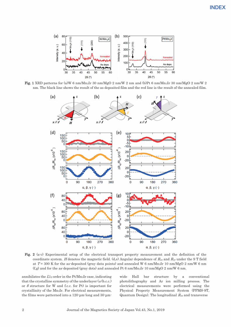
Fig. 2 (a-c) Experimental setup of the electrical transport property measurement and the definition of the coordinate system. H denotes the magnetic field. (d,e) Angular dependence of Rxx and Rxy under the 9 T field at T = 300 K for the as-deposited (gray data points) and annealed W 6 nm/Mn3Ir 10 nm/MgO 2 nm/W 6 nm (f,g) and for the as-deposited (gray dots) and annealed Pt 6 nm/Mn3Ir 10 nm/MgO 2 nm/W 6 nm.
Fig. 1 XRD patterns for (a)W 6 nm/Mn3Ir 30 nm/MgO 2 nm/W 2 nm and (b)Pt 6 nm/Mn3Ir 30 nm/MgO 2 nm/W 2 nm. The black line shows the result of the as deposited film and the red line is the result of the annealed film.

3Journal of the Magnetics Society of Japan Vol.43, No.1, 2019
INDEXINDEX
Rxy resistances were measured with the excitation current of 1 mA (J ~ 2.1 x 10⁵ A/cm2) in a rotating magnetic field with a fixed magnitude (H = 0 ~ 9 T). The excitation current flows along x-axis. The definition of the rotating angles: α, β, and γ are indicated in Figs. 2 (a-c).
3. Results
Figures 2 (d-g) show the magnetoresistance ratio ΔRxx/Rxx and ΔRxy/Rxx as functions of α, β, and γ with H = 9 T before and after annealing. Both W/Mn3Ir and Pt/Mn3Ir samples did not show any α dependent magnetoresistive behaviors before annealing (as indicated in gray data points in Figs. 2 (d-g)). Measurements in other angles β and γ are omitted. On the other hand, after annealing, appreciable magnetoresistances were observed but the behaviors with respect to the rotating angles differ for the two samples. The most intriguing and distinct differences can be seen in the resistance variation with respect to the rotating angle α which are shifted by π/2 between the W/Mn3Ir and Pt/Mn3Ir samples. Figure 3 shows the field dependence of ΔRxx/Rxx in the annealed W/Mn3Ir(a) and Pt/Mn3Ir(b) samples. Figure 3 shows the field dependence of ΔRxx/Rxx in the annealed W/Mn3Ir(a) and Pt/Mn3Ir(b) samples. These ΔRxx/Rxx are summarized in Fig.3(c). The π/2 phase shift is denoted as a different sign of ΔRxx/Rxx between the W/Mn3Ir and Pt/Mn3Ir samples. When H = 0 T, only the noise level of the ΔRxx/Rxx was obtained. ΔRxx/Rxx became larger with increasing the magnitude of H. Although the resistance difference between Rxx(α = 0 degree) and Rxx(α = 180 degree) is unclear, we can conclude that the saturation magnetic field to manipulate the magnetic moments is over 9 T.
4. Discussion In order to step into a quantitative argument
on these intriguing magnetoresistance behaviors, we firstly consider the change in the longitudinal resistance ΔRxx in these multilayer systems. The derivation of the 𝑅𝑅𝑥𝑥𝑥𝑥 change due to the SMR and the AMR can start from 4),24),
𝑅𝑅𝑥𝑥𝑥𝑥 =∑(𝑅𝑅0 + ∆𝑅𝑅𝐴𝐴𝐴𝐴𝐴𝐴𝑚𝑚𝑛𝑛,𝑥𝑥2𝑛𝑛
+ ∆𝑅𝑅𝑆𝑆𝐴𝐴𝐴𝐴(1 − 𝑚𝑚𝑛𝑛,𝑦𝑦2))
(1)
where 𝑅𝑅0 is the field independent resistance, and ∆𝑅𝑅𝐴𝐴𝐴𝐴𝐴𝐴 and ∆𝑅𝑅𝑆𝑆𝐴𝐴𝐴𝐴are the resistance change due to AMR and SMR, respectively. 𝑚𝑚𝑛𝑛,𝑥𝑥 and 𝑚𝑚𝑛𝑛,𝑦𝑦 are respectively a unit vector along x- and y-axis of the nth magnetic sublattice. Here, we left aside a possible magnetoresistance due to the chiral magnetic structure in absence of a detailed quantitative model but will come back to the point in the later argument. Assuming that the external field is large enough to induce the spin-flopping of the AFM and the magnetic anisotropy energy is negligibly small compared to the exchange energy, Equation (1) leads to ΔRxx depending on the net magnetization vector 𝑴𝑴∥ parallel to the external field and 𝑴𝑴⊥ perpendicular to the external field, where 𝑴𝑴∥ is regarded as the ferromagnetic order parameter and 𝑴𝑴⊥ maybe regarded as the antiferromagnetic order parameter, or the Néel vector. Table 1 shows the magnetoresistance ratio ∆𝑅𝑅𝑥𝑥𝑥𝑥 𝑅𝑅⁄ considering SMR and AMR for 𝑴𝑴∥ and 𝑴𝑴⊥. One can notice from the list of the magnetoresistances in Table 1 that the contribution of AMR and SMR can be separated out by having the complete data set for α, β, and γ rotations. Here, the amplitude of the trigonometric functions, AFS, AAS, AFA, and AAA considers the resistance change due to SMR for 𝑴𝑴∥ , SMR for 𝑴𝑴⊥ , AMR for 𝑴𝑴∥ , AMR for 𝑴𝑴⊥ , respectively. We also derive the change in the
Fig. 3 Field dependence of the magnetoresistive signals in the annealed W/Mn3Ir(a) and Pt/Mn3Ir(b) samples. (c)These magnetoresistance ratios are summarized as a function of magnetic field in red dots(Pt/Mn3Ir) and blue dots(W/Mn3Ir).
4 Journal of the Magnetics Society of Japan Vol.43, No.1, 2019
INDEXINDEX
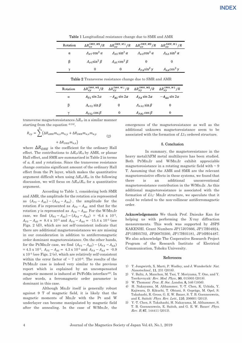
transverse magnetoresistances ΔRxy in a similar manner starting from the equation 4),24),
𝑅𝑅𝑥𝑥𝑥𝑥 =∑(∆𝑅𝑅𝐴𝐴𝐴𝐴𝐴𝐴𝑚𝑚𝑛𝑛,𝑥𝑥𝑚𝑚𝑛𝑛,𝑥𝑥 + ∆𝑅𝑅𝑆𝑆𝐴𝐴𝐴𝐴𝑚𝑚𝑛𝑛,𝑥𝑥𝑚𝑚𝑛𝑛,𝑥𝑥
𝑛𝑛
+ ∆𝑅𝑅𝑂𝑂𝑂𝑂𝑂𝑂𝑚𝑚𝑛𝑛,𝑧𝑧) (2)
where ∆𝑅𝑅𝑂𝑂𝑂𝑂𝑂𝑂 is the coefficient for the ordinary Hall effect. The contributions to ΔRxy/Rxx by AMR, or planar Hall effect, and SMR are summarized in Table 2 in terms of α, β, and γ rotations. Since the transverse resistance change contains significant amount of the ordinary Hall effect from the Pt layer, which makes the quantitative argument difficult when using ΔRxy/Rxx in the following discussion, we will focus on ΔRxx/Rxx for a quantitative argument. According to Table 1, considering both SMR and AMR, the amplitude for the rotation α is represented as (𝐴𝐴𝐹𝐹𝑆𝑆 − 𝐴𝐴𝐴𝐴𝑆𝑆) − (𝐴𝐴𝐹𝐹𝐴𝐴 − 𝐴𝐴𝐴𝐴𝐴𝐴) , the amplitude for the rotation β is represented as 𝐴𝐴𝐹𝐹𝑆𝑆 − 𝐴𝐴𝐴𝐴𝑆𝑆 and that for the rotation γ is represented as 𝐴𝐴𝐹𝐹𝐴𝐴 − 𝐴𝐴𝐴𝐴𝐴𝐴. For the W/Mn3Ir case, we find (𝐴𝐴𝐹𝐹𝑆𝑆 − 𝐴𝐴𝐴𝐴𝑆𝑆) − (𝐴𝐴𝐹𝐹𝐴𝐴 − 𝐴𝐴𝐴𝐴𝐴𝐴) = -6.4 x 10⁻⁵, 𝐴𝐴𝐹𝐹𝑆𝑆 − 𝐴𝐴𝐴𝐴𝑆𝑆 = 8.4 x 10⁻⁵ and 𝐴𝐴𝐹𝐹𝐴𝐴 − 𝐴𝐴𝐴𝐴𝐴𝐴 = -15.4 x 10⁻⁵ (see Figs. 2 (d)), which are not self-consistent indicate that there are additional magnetoresistances we are missing in our consideration in addition to antiferromagnetic order dominant magnetoresistance. On the other hands, for the Pt/Mn3Ir case, we find (𝐴𝐴𝐹𝐹𝑆𝑆 − 𝐴𝐴𝐴𝐴𝑆𝑆) − (𝐴𝐴𝐹𝐹𝐴𝐴 − 𝐴𝐴𝐴𝐴𝐴𝐴) = 4.5 x 10⁻⁵, 𝐴𝐴𝐹𝐹𝑆𝑆 − 𝐴𝐴𝐴𝐴𝑆𝑆 = 4.3 x 10⁻⁵ and 𝐴𝐴𝐹𝐹𝐴𝐴 − 𝐴𝐴𝐴𝐴𝐴𝐴 = -0.9 x 10⁻⁵ (see Figs. 2 (e), which are relatively self-consistent within the error factor of ~ 7 x10⁻⁶. The results of the Pt/Mn3Ir case is indeed very similar to the previous report which is explained by an uncompensated magnetic moment is induced at Pt/FeMn interface25). In other words, a ferromagnetic order parameter is dominant in this case.
Although Mn3Ir itself is generally robust against 9 T of magnetic field, it is likely that the magnetic moments of Mn3Ir with the Pt and W underlayer can become manipulated by magnetic field after the annealing. In the case of W/Mn3Ir, the
emergences of the magnetoresistance as well as the additional unknown magnetoresistance seem to be associated with the formation of L12 ordered structure.
5. Conclusion
In summary, the magnetoresistance in the
heavy metal/AFM metal multilayers has been studied. Both Pt/Mn3Ir and W/Mn3Ir exhibit appreciable magnetoresistance in a rotating magnetic field with ~ 9 T. Assuming that the AMR and SMR are the relevant magnetoresistive effects in these systems, we found that there is an additional unconventional magnetoresistance contribution in the W/Mn3Ir. As this additional magnetoresistance is associated with the formation of L12- Mn3Ir structure, we speculate that it could be related to the non-collinear antiferromagnetic order. Acknowledgements We thank Prof. Daisuke Kan for helping us with performing the X-ray diffraction measurements. This work was supported by JSPS KAKENHI. Grant Numbers JP17J07666, JP17H04924, JP15H05702, JP26870300, JP17H05181, JP16H04487. We also acknowledge The Cooperative Research Project Program of the Research Institute of Electrical Communication, Tohoku University.
References
1) T. Jungwirth, X. Marti, P. Wadley, and J. Wunderlich: Nat.
Nanotechnol., 11, 231 (2016). 2) V. Baltz, A. Manchon, M. Tsoi, T. Moriyama, T. Ono, and Y.
Tserkovnyak: Rev. Mod. Phys., 90, 015005 (2018). 3) W. Thomson: Proc. R. Soc. London, 8, 546 (1856). 4) H. Nakayama, M. Althammer, Y.-T. Chen, K. Uchida, Y.
Kajiwara, D. Kikuchi, T. Ohtani, S. Geprägs, M. Opel, S. Takahashi, R. Gross, G. E. W. Bauer, S. T. B. Goennenwein, and E. Saitoh: Phys. Rev. Lett., 110, 206601 (2013).
5) Y.-T. Chen, S. Takahashi, H. Nakayama, M. Althammer, S. T. B. Goennenwein, E. Saitoh, and G. E. W. Bauer: Phys. Rev. B, 87, 144411 (2013).
Table 1 Longitudinal resistance change due to SMR and AMR
Table 2 Transverse resistance change due to SMR and AMR

5Journal of the Magnetics Society of Japan Vol.43, No.1, 2019
INDEXINDEX
6) L. Neel: Nobel Lect., (1970). 7) X. Marti, I. Fina, C. Frontera, J. Liu, P. Wadley, Q. He, R.
J. Paull, J. D. Clarkson, J. Kudrnovský, I. Turek, J. Kuneš, D. Yi, J. H. Chu, C. T. Nelson, L. You, E. Arenholz, S. Salahuddin, J. Fontcuberta, T. Jungwirth, and R. Ramesh: Nat. Mater., 13, 367 (2014).
8) T. Moriyama, N. Matsuzaki, K. J. Kim, I. Suzuki, T. Taniyama, and T. Ono: Appl. Phys. Lett., 107, 122403 (2015).
9) D. Hou, Z. Qiu, J. Barker, K. Sato, K. Yamamoto, S. Vélez, J. M. Gomez-Perez, L. E. Hueso, F. Casanova, and E. Saitoh: Phys. Rev. Lett., 118, 147202 (2017).
10) G. R. Hoogeboom, A. Aqeel, T. Kuschel, T. T. M. Palstra, and B. J. van Wees: Appl. Phys. Lett., 111, 052409 (2017).
11) J. Fischer, O. Gomonay, R. Schlitz, K. Ganzhorn, N. Vlietstra, M. Althammer, H. Huebl, M. Opel, R. Gross, S. T. B. Goennenwein, and S. Geprägs: Phys. Rev. B, 97, 014417 (2018).
12) X. Z. Chen, R. Zarzuela, J. Zhang, C. Song, X. F. Zhou, G. Y. Shi, F. Li, H. A. Zhou, W. J. Jiang, F. Pan, and Y. Tserkovnyak: Phys. Rev. Lett., 120, 207204 (2018).
13) P. Wadley, B. Howells, J. Železný, C. Andrews, V. Hills, R. P. Campion, V. Novák, K. Olejník, F. Maccherozzi, S. S. Dhesi, S. Y. Martin, T. Wagner, J. Wunderlich, F. Freimuth, Y. Mokrousov, J. Kuneš, J. S. Chauhan, M. J. Grzybowski, A. W. Rushforth, K. W. Edmonds, B. L. Gallagher, and T. Jungwirth: Science, 351, 587 (2016).
14) S. Y. Bodnar, L. Šmejkal, I. Turek, T. Jungwirth, O. Gomonay, J. Sinova, A. A. Sapozhnik, H.-J. Elmers, M. Kläui, and M. Jourdan: Nat. Commun., 9, 348 (2018).
15) M. Meinert, D. Graulich, and T. Matalla-Wagner: Phys. Rev. Appl., 9, 64040 (2017).
16) X. F. Zhou, J. Zhang, F. Li, X. Z. Chen, G. Y. Shi, Y. Z. Tan,
Y. D. Gu, M. S. Saleem, H. Q. Wu, F. Pan, and C. Song: Phys. Rev. Appl., 9, 054028 (2018).
17) H. Chen, Q. Niu, and A. H. MacDonald: Phys. Rev. Lett., 112, 017205 (2014).
18) S. Nakatsuji, N. Kiyohara, and T. Higo: Nature, 527, 212 (2015).
19) J. Nogués and I. K. Schuller: J. Magn. Magn. Mater., 192, 203 (1999).
20) Y. Y. Wang, C. Song, J. Y. Zhang, and F. Pan: Prog. Nat. Sci. Mater. Int., 27, 208 (2017).
21) I. Tomeno, H. N. Fuke, H. Iwasaki, M. Sahashi, and Y. Tsunoda: J. Appl. Phys., 86, 3853 (1999).
22) We did field cooled with an external field of 0.3 T in separate W(6 nm)/Mn3Ir(10 nm)/FeCoB(4 nm) and Pt(6 nm)/Mn3Ir(10 nm)/FeCoB(4 nm) samples to confirm its antiferromagnetic order by observing exchange bias. The magnitude of the exchange bias were estimated from the planar Hall effect by using a fitting function that we reported before in K. Oda, T. Moriyama, M. Kawaguchi, M. Kamiya, K. Tanaka, K.-J. Kim, and T. Ono: Jpn. J. Appl. Phys., 55, 070304 (2016). As a result, exchange bias in the former structure showed 0.0106 T while in latter structure was 0.0416 T.
23) A. Kohn, A. Kovács, R. Fan, G. J. McIntyre, R. C. C. Ward, and J. P. Goff: Sci. Rep., 3, 2412 (2013).
24) T. R. Mcguire and R. I. Potter: IEEE Trans. Magn., 11, 1018 (1975).
25) Y. Yang, Y. Xu, X. Zhang, Y. Wang, S. Zhang, R. W. Li, M. S. Mirshekarloo, K. Yao, and Y. Wu: Phys. Rev. B, 93, 094402 (2016).
Received Aug. 13, 2018; Accepted Nov. 19, 2018
6 Journal of the Magnetics Society of Japan Vol.43, No.1, 2019
INDEXINDEX
J. Magn. Soc. Jpn., 43, 6-10 (2019)<Paper>
High coercivity and resolution FePt•MgO-coated tip for imaging the magnetic field of perpendicular magnetic write head by alternating magnetic force microscopy (A-MFM)
F. Zheng1,2, S. Yoshimura3, S. Yasui3, G. Egawa3, and H. Saito3
1Venture Business Laboratory, Akita University, Tegata Gakuen-machi 1-1, Akita 010–8502, Japan 2School of Physics and Electronic-Electrical Engineering, Ningxia University, Yinchuan 750021, China 3Research Center for Engineering Science, Graduate School of Engineering Science, Akita University,
Tegata Gakuen-machi 1-1, Akita 010–8502, Japan
High coercivity FePt•MgO films were successfully synthetized on cone-shape Si tips in a very high frequency (VHF) plasma irradiation-assisted magnetron sputtering system to prepare the MFM tips for evaluation of the AC magnetic field of perpendicular magnetic write head at high write current. Alloying with MgO significantly enhanced the coercivity of the magnetic coating due to the isolation of FePt grains by MgO. As a result, a high coercivity close to 20 kOe was achieved. The AC magnetic field images of the perpendicular magnetic write head at high write current were taken on alternating MFM (A-MFM) by this tip. A clear amplitude image with a strong signal at the main pole position was observe compared to the pure FePt layer-coated tip, which gave a blurry image and very small amplitude. Fourier analysis of the images obtained by this kind of FePt•MgO tip gives a spatial resolution of about 15 nm in air atmosphere. It is clear that the cone-shape FePt•MgO-coated MFM tip with a coercivity higher than the magnetic field to be measured is effective and capable for measuring the high AC magnetic field for an HD perpendicular magnetic write head at a very high write current. Key words: high-coercivity and high-resolution FePt•MgO-coated tip, very high frequency (VHF) plasma irradiation, perpendicular magnetic write head, alternating magnetic force microscopy (A-MFM)
1. Introduction
Magnetic force microscopy (MFM) is an effective scanning probe for investigation of the magnetic domain structures of magnetic materials in nanoscale such as magnetic recording media because of its high spatial resolution of the static magnetic field1). The MFM tip is the most important key element to detect and image the surficial magnetic signal of an object. A high coercivity magnetic tip is one of the essential parameters for MFM imaging. Commercially-available MFM tip is usually an atomic force microscopy (AFM) tip coated with a thin CoCrPt film. There have been many efforts to prepare MFM tips such as synthetic antiferromagnetic coating with sandwich structures2),3), focused ion beam (FIB) trimming4)-6), carbon nanotubes coated with magnetic films7),8). Hard magnetic coatings of Fe-Pt9)-13), Fe-Pd13),14), Co-Pt15)-18), Sm-Co19) were used for the preparation of MFM tips to image large magnetic field. In addition to the MFM tip, the methodology of MFM itself is also critical. We have developed a new MFM imaging method for characterization of AC magnetic field. We named it as alternating MFM (A-MFM)20). The A-MFM uses a frequency modulation (FM) of the cantilever oscillation by applying an AC magnetic field on a mechanically oscillated tip. This can allow us to measure the perpendicular component of the AC magnetic field with respect to the sample surface. Previously, we used in-house-coated FePt tips with high-coercivity to image the
AC magnetic field of a perpendicular magnetic write head having a one-sided trailing shield on our A-MFM set up21),22),23). The spatial resolution was estimated to be 15 nm (a lift height of 1 nm and AC current with a zero-to-peak amplitude of 20 mA). However, this tip failed to characterize the AC magnetic field of the head having three surrounding shields when a large write current which generates a large magnetic field bigger than the coercivity of the FePt coating on the tip. To estimate the distribution of magnetic field from the head having three surrounding shields, MFM tip with symmetry shape for the magnetic charge and with high coercivity magnetic film is effective. We had reported the cone-shaped MFM tip with symmetry for the magnetic charge to get a MFM image without distortion24). We also had reported that coercivity of the FePt coated MFM tip is lower than the magnetic field generated by the head having three surrounding shields with large head current24).
We deposited FePt•MgO films on the tip by VHF plasma irradiation-assisted magnetron sputtering in order to increase the coercivity of magnetic FePt film. The MgO25) was used for isolation of FePt grains. The VHF plasma irradiation enhanced the L10 FePt phase during sputtering26). The new FePt•MgO MFM tip with very high coercivity was used for observation of AC magnetic image of perpendicular magnetic write head in this work.
7Journal of the Magnetics Society of Japan Vol.43, No.1, 2019
INDEXINDEX
2. Experimental Procedure
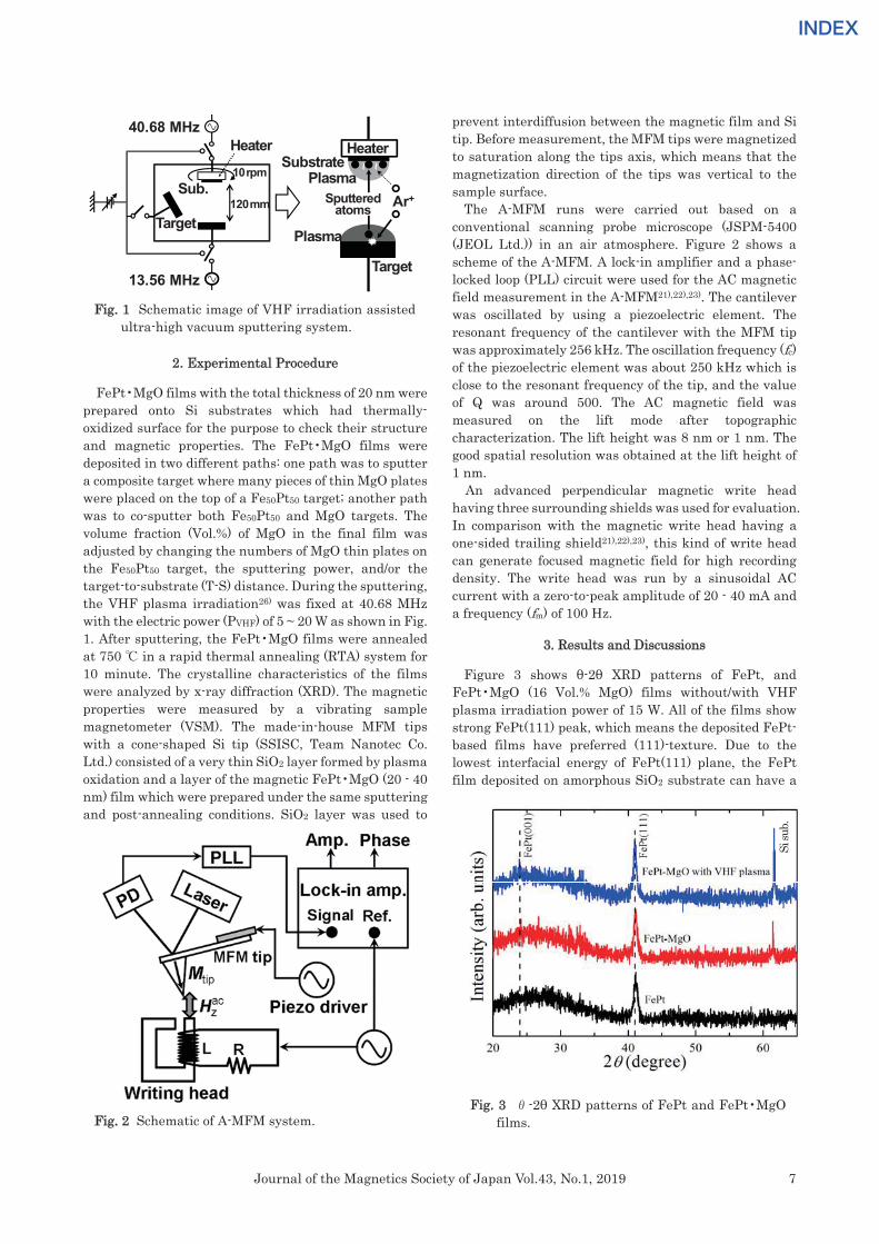
FePt•MgO films with the total thickness of 20 nm were prepared onto Si substrates which had thermally-oxidized surface for the purpose to check their structure and magnetic properties. The FePt•MgO films were deposited in two different paths: one path was to sputter a composite target where many pieces of thin MgO plates were placed on the top of a Fe50Pt50 target; another path was to co-sputter both Fe50Pt50 and MgO targets. The volume fraction (Vol.%) of MgO in the final film was adjusted by changing the numbers of MgO thin plates on the Fe50Pt50 target, the sputtering power, and/or the target-to-substrate (T-S) distance. During the sputtering, the VHF plasma irradiation26) was fixed at 40.68 MHz with the electric power (PVHF) of 5 ~ 20 W as shown in Fig. 1. After sputtering, the FePt•MgO films were annealed at 750 ℃ in a rapid thermal annealing (RTA) system for 10 minute. The crystalline characteristics of the films were analyzed by x-ray diffraction (XRD). The magnetic properties were measured by a vibrating sample magnetometer (VSM). The made-in-house MFM tips with a cone-shaped Si tip (SSISC, Team Nanotec Co. Ltd.) consisted of a very thin SiO2 layer formed by plasma oxidation and a layer of the magnetic FePt•MgO (20 - 40 nm) film which were prepared under the same sputtering and post-annealing conditions. SiO2 layer was used to
prevent interdiffusion between the magnetic film and Si tip. Before measurement, the MFM tips were magnetized to saturation along the tips axis, which means that the magnetization direction of the tips was vertical to the sample surface.
The A-MFM runs were carried out based on a conventional scanning probe microscope (JSPM-5400 (JEOL Ltd.)) in an air atmosphere. Figure 2 shows a scheme of the A-MFM. A lock-in amplifier and a phase-locked loop (PLL) circuit were used for the AC magnetic field measurement in the A-MFM21),22),23). The cantilever was oscillated by using a piezoelectric element. The resonant frequency of the cantilever with the MFM tip was approximately 256 kHz. The oscillation frequency (fc) of the piezoelectric element was about 250 kHz which is close to the resonant frequency of the tip, and the value of Q was around 500. The AC magnetic field was measured on the lift mode after topographic characterization. The lift height was 8 nm or 1 nm. The good spatial resolution was obtained at the lift height of 1 nm.
An advanced perpendicular magnetic write head having three surrounding shields was used for evaluation. In comparison with the magnetic write head having a one-sided trailing shield21),22),23), this kind of write head can generate focused magnetic field for high recording density. The write head was run by a sinusoidal AC current with a zero-to-peak amplitude of 20 - 40 mA and a frequency (fm) of 100 Hz.
3. Results and Discussions
Figure 3 shows θ-2θ XRD patterns of FePt, and FePt•MgO (16 Vol.% MgO) films without/with VHF plasma irradiation power of 15 W. All of the films show strong FePt(111) peak, which means the deposited FePt-based films have preferred (111)-texture. Due to the lowest interfacial energy of FePt(111) plane, the FePt film deposited on amorphous SiO2 substrate can have a
Fig. 1 Schematic image of VHF irradiation assisted ultra-high vacuum sputtering system.
40.68 MHz
13.56 MHz
120mm
10rpm
Target
Sub.
Substrate
Target
Ar+
~~
HeaterHeater
Plasma
PlasmaSputtered
atoms
Fig. 2 Schematic of A-MFM system. Fig. 3 θ-2θ XRD patterns of FePt and FePt•MgO
films.
Si su
b.

8 Journal of the Magnetics Society of Japan Vol.43, No.1, 2019
INDEXINDEX
(111)-favor texture growth. In Fig.3 you cannot see a clear (001) peak, but the sputtering film with VHF plasma irradiation shows an enhanced (111) peak intensity, compared to the films without VHF plasma irradiation. The integral intensity of FePt(111) was 4853, 5155, and 6763, for the films of FePt, FePt•MgO, and FePt•MgO with VHF plasma, respectively. In our previous study26), a VHF plasma irradiation during sputtering deposition can effectively accelerate crystallization and atom ordering. It is believed that the VHF plasma irradiation can also accelerate the crystallization and ordering of L10 FePt phase. As we know, the high magnetic anisotropy of FePt films can be obtained in the chemically ordering state, which can lead to high coercivity.
An in-plane easy axis of magnetization of the magnetic coating on is preferred for MFM tip preparation. Figure 4 shows the dependence of the in-plane coercivity of FePt•MgO films on the volume fraction of MgO. The inset shows hysteresis loops of FePt and (FePt)84•(MgO)16 film (in Vol.%), respectively. The coercivity rises from 9.2 kOe to 17.0 kOe when MgO’s volume percentage in FePt•MgO film increases from 0 to 35 Vol.%. It is obvious that MgO addition to the FePt film significantly enhance the coercivity of the film. This is believed that the MgO’s effect of isolation of FePt grains attributes to increased coercivity like the other kinds of element additives such as SiO227), C28), TiO229),30) added to FePt-base films.
Figure 5 shows the in-plane coercivity of FePt•MgO films versus the VHF plasma irradiation power. The inset shows hysteresis loops of (FePt)84•(MgO)16 film with VHF plasma irradiation power of 15 W. As shown in the figure, the coercivity gradually increases from 14.5 kOe to 15.9 kOe when VHF power changes from 5 W to 15 W. And then coercivity drops to 15.2 kOe as VHF power goes up to 20 W. The VHF bias is considered to have two effects: 1) the enhancement of atoms/ molecules’
mobility for ordering and 2) the ion bombardment on film during sputtering. The effect 1) of VHF bias is taking place to increase coercivity when the VHF power is low. This is supported by XRD measurement shown in Figure 3. The effect 2) of VHF bias becomes dominant and enhances disordering atoms/ molecules of FePt in the film so to reduce in-plane coercivity when VHF power is high. The highest in-plane coercivity achieved at the composition of 16 Vol.% MgO under a proper VHF plasma irradiation during sputtering suggests the importance of both FePt atoms ordering and MgO molecules’ isolation effects for making high coercivity films. This is also supported by the (FePt)65•(MgO)35 film’s behavior as shown in Figure 5. It is clearer that an optimized VHF bias power (enhancement of FePt ordering) and more MgO concentration (more isolations of FePt grains) can give higher in-plane coercivity (more than 20 kOe) to FePt films.
The two kinds of MFM tips with FePt and (FePt)84•(MgO)16 coatings were fabricated for evaluation of the AC magnetic field of a write head having three surrounding shields. The (FePt)84•(MgO)16 film was formed under a VHF plasma irradiation power of 15 W. The nominal thickness of both FePt-base coatings was 40 nm. Here, we discussed the evaluation of magnetic properties of MFM tips by using pulsed magnetic field magnetic force microscope31), and also estimated the coercivity of MFM tips32). The measured coercivity of FePt•MgO MFM tips was closed to the values of FePt•MgO films. The A-MFM measurement was taken at a lift height of 8 nm. The head write current was 40 mA. Figs.6 (a) shows the topographic image of the write head around the main pole area.
The amplitude images of AC magnetic field generated from the write head measured by the FePt-coated tip and (FePt)84•(MgO)16-coated tip having an coercivity of 15.9 kOe is clear and has high amplitude signal at the main pole position. In contrast, the amplitude image measured
Fig. 4 The in-plane coercivity versus MgO volume fraction in FePt•MgO films. The inset shows hysteresis loops of FePt and (FePt)84•(MgO)16
film.
Fig. 5 Dependence of the in-plane coercivity of FePt•MgO films on the VHF plasma irradiation power. The inset is hysteresis loop of (FePt)84•(MgO)16 with VHF plasma irradiation power of 15 W.

9Journal of the Magnetics Society of Japan Vol.43, No.1, 2019
INDEXINDEX
by FePt-coated tip having a coercivity of 9.2 kOe is unclear and has very low amplitude signal at the main pole position. In contrast, the amplitude image measured by FePt-coated tip having a coercivity of 9.2 kOe is unclear and has very low amplitude signal at the main pole position. These results indicate that the FePt•MgO-coated tip with a coercivity higher than the field generated from the write head can effectively image the AC magnetic field without signal decay because the high coercivity can suppress the tip’s magnetization rotation. In one word, the clear amplitude image is obtained by the FePt•MgO-coated tip with a high coercivity in this case.
In order to clarify and enhance the spatial resolution of our High coercivity MFM tips, a 20 nm-thick (FePt)84•(MgO)16-coated tip was fabricated under the same conditions as above. Figs.7 (a) and (b) are amplitude and phase images of the AC magnetic field for a magnetic write head measured by this tip. The lift height was fixed at 1 nm. The head write current was also 40 mA. Figs.7 (c) and (d) are down track line profiles of amplitude and phase signal over the white line locations in Figs.7 (a) and (b), respectively. The clear amplitude image and high amplitude signal at the main pole position are achieved again. This further indicates that the MFM tip with a coercivity higher than the AC magnetic field to be measured can effectively image the AC magnetic field without signal decay. The phase image near the main pole region was measured in the same scan. The phase difference between the bright and dark area was about 180o as shown in the line profile of Figs.7 (d). When the direction of the perpendicular AC magnetic
field is reversed from Hzac to -Hzac, the input signal of a lock-in amplifier changes in the following way.
(1) Therefore, the areas with bright and dark colors in the phase image correspond to the opposite directions of perpendicular magnetic field. In another words, the phase image gives the polarity of the AC magnetic field vertical to the surface measured.
Figs.7 (e) shows the spatial resolution of the amplitude imaging. The resolution is obtained from Fourier transformation of the amplitude scan line around main pole. The details of this calculation were described in reference papers21). The spatial resolution of amplitude imaging is 15.5 nm in this case. This value is very close to the result of our previous study. Here, the coercivity of FePt•MgO films maintains more than 15 kOe, even if its film thickness is reduced to 10 nm. Therefore, the FePt•MgO MFM tip with the thin FePt•MgO film is expected to be useful for improvement of the spatial resolution owing to the reduction of diameter of end point of the tip. In consideration of that the head structure having three surrounding shields and a high write current of 40 mA, the high coercivity FePt•MgO-coated MFM tip is so successful in imaging such high magnetic field from the head.
4. Conclusion
In-plane (111)-textured FePt and FePt•MgO films were deposited on pre-oxidized Si substrates and Si tips for the study of the effect of coercivity of magnetic coatings on MFM tips. The coercivity of FePt•MgO coatings rises when increasing the MgO’s concertation in FePt•MgO alloys under an optimized VHF plasma
Fig. 6 (a) is a topographic image, (b) and (c) are amplitude images of the AC magnetic field for the magnetic write head, and (d) is down track line profiles of amplitude signal of the white line in (b) and (c). The images in (b) and (c) are obtained using the FePt- and FePt•MgO-coated tips, respectively.
Fig. 7 (a) amplitude and (b) phase images of the AC magnetic field for the magnetic write head measured by 20 nm (FePt)84•(MgO)16 -coated tip. (c) and (d) are down track line profiles of amplitude and phase signal of the white line in (a) and (b), respectively. (e) is the spatial resolution result of the amplitude image.
ーHzac cos(mt) = Hz
ac cos(mt+)
10 Journal of the Magnetics Society of Japan Vol.43, No.1, 2019
INDEXINDEX
irradiation power. The high coercivity of FePt•MgO films is believed due to the isolation of FePt grains by MgO and enhancement of atomic ordering of FePt by a VHF bias. A clear amplitude image and high amplitude signal at the main pole position were observed by using this High coercivity FePt•MgO tip. The spatial resolution of this type of MFM tip is around 15 nm. As simply speaking, the cone-shape FePt•MgO-coated MFM tip with a coercivity higher than the magnetic field to be measured is effective and capable to measure the high AC magnetic field for a perpendicular magnetic write head at a very high write current. Acknowledgements This work was supported by JST/SENTAN.
References
1) D. Rugar, H. J. Mamin, P. Guethner, S. E. Lambert, J. E. Stern, I. Mc-Fadyen, and T. Yogi: J. Appl. Phys., 68, 1169 (1990).
2) Y. H. Wu, Y. T. Shen, Z. Y. Liu, K. B. Li, and J. J. Qiu: Appl. Phys. Lett., 82, 1748 (2003).
3) N. Amos, R. Ikkawi, R. Haddon, D. Litvinov, and S. Khizroev: Appl. Phys. Lett., 93, 203116 (2008).
4) Z. Y. Liu, Y. Dan, J. J. Qiu, and Y. H. Wu: J. Appl. Phys., 91, 8843 (2002).
5) L. Gao, L. P. Yue, T. Yokota, R. Skomski, S. H. Liou, H. Takahoshi, H. Saito, and S. Ishio: IEEE Trans. Magn., 40, 2194 (2004).
6) C. Hyun, A. K. H. Lee, and A. d. Lozanne: Nanotechnology, 17, 921 (2006).
7) Z. F. Deng, E. Yenilmez, J. Leu, J. E. Hoffman, E. W. J. Straver, H. J. Dai, and K. A. Moler: Appl. Phys. Lett., 85, 6263 (2004).
8) F. Wolny, T. Mühl, U. Weissker, K. Lipert, J. Schumann, A. Leonhardt, and B. Büchner: Nanotechnology, 21, 435501 (2010).
9) Y Rheem, H Saito, and S Ishio: IEEE Trans. Magn., 41, 3793 (2005).
10) I.C. Chen, L.H. Chen, A. Gapin, S. Jin, L. Yuan, and S.H. Liou: Nanotechnology, 19, 075501 (2008).
11) N. Amos, A. Lavrenov, R. Fernandez, R. Ikkawi, D. Litvinov, and S. Khizroev: J. Appl. Phys., 105, 07D526 (2009).
12) N. Amos, R. Fernandez, R.M. Ikkawi, M. Shachar, J.M. Hong, B.S. Lee, D. Litvinov, and S. Khizroev: IEEE Magn. Lett., 1, 6500104 (2010).
13) S. Ishihara, M. Ohtake, and M. Futamoto: Thin Solid Films, 546, 205 (2013).
14) S. Ishihara, M. Ohtake, and M. Futamoto: EPJ Web Conf., 40, 08003 (2013).
15) S.H Liou and Y.D Yao: J. Magn. Magn. Mater., 190, 130 (1998).
16) S. Ishihara, T. Hagami, K. Soneta, M. Ohtake, and M. Futamoto: J. Magn. Soci. Jpn., 37, 56 (2013).
17) S. Ishihara, M. Ohtake, and M. Futamoto: J Magn. Soci. Jpn., 37, 255 (2013).
18) S. Ishihara, M. Ohtake, and M. Futamoto: EPJ Web Conf., 75, 06007 (2014).
19) V. Neu, T. Sturm, S. Vock, and L. Schultz: IEEE International Magnetics Conference (INTERMAG Europe 2014), EG-6 (2014).
20) H. Saito, H. Ikeya, G. Egawa, S. Ishio, and S. Yoshimura: J. Appl. Phys., 105, 07D524 (2009).
21) W. Lu, Z. H. Li, K. Hatakeyama, G. Egawa, S. Yoshimura, and H. Saito: Appl. Phys. Lett., 96, 143104 (2010).
22) W. Lu, K. Hatakeyama, G. Egawa, S. Yoshimura, and H. Saito: IEEE Trans. Magn., 46, 1479 (2010).
23) H. Saito: Magune, 11, 217 (2016). 24) S. Yoshimura, F. Zheng, S. Yasui, G. Egawa, and H. Saito: J.
Magn. Soc. Jpn., 42, 5 (2018). 25) Z. Zhang, K. Kang, Kyongha, and T. Suzuki: IEEE Trans.
Magn., 40, 2455 (2004). 26) S. Yoshimura, H. Kobayashi, G. Egawa, H. Saito, and S.
Ishida: J. Appl. Phys., 109, 07B751 (2011). 27) C. P. Luo and D. J. Sellmyer: Appl. Phys. Lett., 75, 3162
(1999). 28) J. S. Chen, B. C. Lim, J. F. Hu, B. Liu, G. M. Chow, and G.
Ju: Appl. Phys. Lett., 91, 132506 (2007). 29) Y. F. Ding, J. S. Chen, B. C. Lim, J. F. Hu, B. Liu, and G. Ju:
Appl. Phys., Lett., 93, 032506 (2008). 30) C. J. Jiang, J. S. Chen, J. F. Hu, and G. M. Chow: J. Appl.
Phys., 107, 123915 (2010). 31) Y. Zheng, S. Yoshimura, G. Egawa, F. Zheng, Y. Kinoshita
and H. Saito: J. Phys. D: Appl. Phys., 48, 335006, (2015). 32) F. Zheng, S. Yoshimura, Y. Zheng, G. Egawa, Y. Kinoshita,
and H. Saito: IEEE International Magnetics Conference (INTERMAG EUROPE 2014), CS-17 (2014)
Received Nov. 23, 2016; Revised Aug. 28, 2018; Accepted Nov. 05, 2018
11Journal of the Magnetics Society of Japan Vol.43, No.1, 2019
INDEXINDEX
J. Magn. Soc. Jpn., 43, 11-16 (2019)<Paper>
Evaluation on Edge-supported Magnetic Levitation Apparatus for Thin Steel Plates
Y. Oda, Y. Ito, K. Okuno, M. Kida, T. Suzuki,
A. Endo, T. Narita*, H. Kato* and H. Moriyama* Course of Mechanical Engineering, Graduate School of Tokai Univ., 4-1-1 Kitakaname, Hiratsuka-shi, Kanagawa 259-1292, Japan
* Department of Prime Mover Engineering, Tokai Univ.
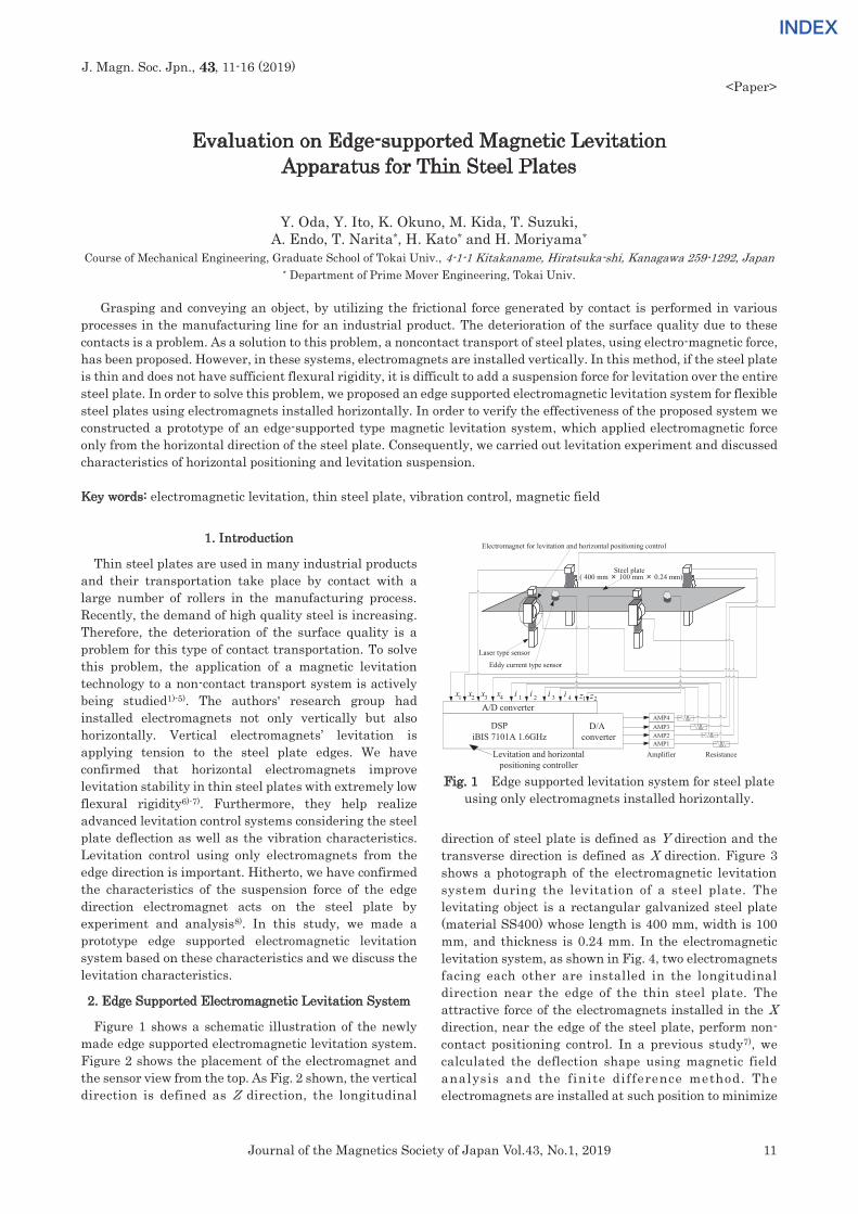
Grasping and conveying an object, by utilizing the frictional force generated by contact is performed in various processes in the manufacturing line for an industrial product. The deterioration of the surface quality due to these contacts is a problem. As a solution to this problem, a noncontact transport of steel plates, using electro-magnetic force, has been proposed. However, in these systems, electromagnets are installed vertically. In this method, if the steel plate is thin and does not have sufficient flexural rigidity, it is difficult to add a suspension force for levitation over the entire steel plate. In order to solve this problem, we proposed an edge supported electromagnetic levitation system for flexible steel plates using electromagnets installed horizontally. In order to verify the effectiveness of the proposed system we constructed a prototype of an edge-supported type magnetic levitation system, which applied electromagnetic force only from the horizontal direction of the steel plate. Consequently, we carried out levitation experiment and discussed characteristics of horizontal positioning and levitation suspension. Key words: electromagnetic levitation, thin steel plate, vibration control, magnetic field
1. Introduction
Thin steel plates are used in many industrial products and their transportation take place by contact with a large number of rollers in the manufacturing process. Recently, the demand of high quality steel is increasing. Therefore, the deterioration of the surface quality is a problem for this type of contact transportation. To solve this problem, the application of a magnetic levitation technology to a non-contact transport system is actively being studied1)-5). The authors' research group had installed electromagnets not only vertically but also horizontally. Vertical electromagnets’ levitation is applying tension to the steel plate edges. We have confirmed that horizontal electromagnets improve levitation stability in thin steel plates with extremely low flexural rigidity6)-7). Furthermore, they help realize advanced levitation control systems considering the steel plate deflection as well as the vibration characteristics. Levitation control using only electromagnets from the edge direction is important. Hitherto, we have confirmed the characteristics of the suspension force of the edge direction electromagnet acts on the steel plate by experiment and analysis8). In this study, we made a prototype edge supported electromagnetic levitation system based on these characteristics and we discuss the levitation characteristics.
2. Edge Supported Electromagnetic Levitation System
Figure 1 shows a schematic illustration of the newly
made edge supported electromagnetic levitation system. Figure 2 shows the placement of the electromagnet and the sensor view from the top. As Fig. 2 shown, the vertical direction is defined as Z direction, the longitudinal
Fig. 1 Edge supported levitation system for steel plate using only electromagnets installed horizontally.
direction of steel plate is defined as Y direction and the transverse direction is defined as X direction. Figure 3 shows a photograph of the electromagnetic levitation system during the levitation of a steel plate. The levitating object is a rectangular galvanized steel plate (material SS400) whose length is 400 mm, width is 100 mm, and thickness is 0.24 mm. In the electromagnetic levitation system, as shown in Fig. 4, two electromagnets facing each other are installed in the longitudinal direction near the edge of the thin steel plate. The attractive force of the electromagnets installed in the X direction, near the edge of the steel plate, perform non-contact positioning control. In a previous study7), we calculated the deflection shape using magnetic field analysis and the finite difference method. The electromagnets are installed at such position to minimize
A/D converterx2 x3x1 x4 i 1 i 4i 3i 2
AMP1AMP2AMP3AMP4
DSPiBIS 7101A 1.6GHz
D/Aconverter
ResistanceAmplifier
z1 z2
Steel plate( 400 mm × 100 mm × 0.24 mm)
Laser type sensor
Levitation and horizontalpositioning controller
Eddy current type sensor
Electromagnet for levitation and horizontal positioning control

12 Journal of the Magnetics Society of Japan Vol.43, No.1, 2019
INDEXINDEX
Fig. 2 Schematic illustration of the edge supported levitation system.
Fig. 3 Photograph of the electromagnetic levitation
system.
deflection and to expect stability on the steel plate. A laser-type sensor, which measure the displacement by the cut -o f f amount o f a be l t - l ike laser beam manufactured by KEYENCE was used to measure the horizontal displacement in X direction of the edge of the steel plate. Thereby, the steel plate is controlled by non-contact positioning by the electromagnets at a distance of 5 mm from the edge of the steel plate. Furthermore, the control law is calculated by detecting the current in each electromagnet from the measured external resistance and, subsequently, inputting eight measurement values into a digital signal processor of an A/D converter. The core, shown in Fig. 5, is an E-type electromagnet, and the material is ferrite. The electromagnet ’s core is an enamel wire of 0.5 mm diameter wound around it 1005 times. For evaluating the
Fig. 4 Placement of electromagnet and displacement
field sensor.
Fig. 5 Configuration of the electromagnet.
Fig. 6 Position of eddy current type noncontact
displacement sensor.
levitating state of the steel plate, a vertical direction displacement sensor was installed as shown in Fig. 4 and Fig. 6. An eddy current non-contact displacement sensor manufactured by SENTEC was used. To consider the characteristic of suspension force generated by electromagnet, electromagnetic analysis was carried out. The analytical model is consisting of one electromagnet and steel plate (400 mm × 100 mm). The suspension force
Electromagnetic for levitation and horizontal positing control
Laser type sensor
Eddy current type noncontact displacement sensor
Steel plate
Z Y
X
Laser type sensor
Electromagnet for levitation and horizontal positioning control
Steel plate
400
mm
220
mm
100 mm
Y
X
8 8
14 16 60 16
28 36
Coil
Ferrite core
( 1005 turns )
[mm]
8 mmDisplacement zZ0=0 mm
Steel plate
ElectromagnetEddy current type noncontact displacement sensor
x
z
0

13Journal of the Magnetics Society of Japan Vol.43, No.1, 2019
INDEXINDEX
Fig. 7 Relationship between the vertical attractive force fz for each displacement Z0.
Fig. 8 Coordinate of static levitating steel plate.
Fig. 9 Schematic illustration of attractive force of
electromagnets.
was analyzed in the case that the steady current and vertical displacement of the steel plate is changed. Figure 7 shows the relationship between the vertical direction suspension force and the steady current in the electromagnet, which is obtained from the magnetic analysis. Each data shows the suspension force that was applied on the steel plate in the z direction from the center of the electromagnet core. The dashed line (0.18 N) in the figure means the quarter weight of the steel plate, which is equal to suspension force for levitation generated by one electromagnet in this system. It is possible to levitate the steel plate at a steady current value that corresponds to the steel plate’s weight.
3. Control Model of Edge Supported Electromagnetic Levitation System
3.1 Equation of motion for levitated thin steel plate As shown in Fig. 8, edge of the steel plate is displaced from electromagnet surface in the x direction xsp [mm] and from center of electromagnet in the z direction zsp [mm], when the steel plate is levitate horizontally in equilibrium state. Attractive force by magnetic field from installed electromagnet is generated near edge of the steel plate8). From the previous study, in the electromagnet core and the steel plate size used in this study, the suction force is regarded generated in one point in the edge of steel plate. We confirmed that the
attractive force generated on the steel plate by the electromagnet is generated toward the tip of center convex part of the electromagnet core. Attractive force F generated on the steel plate is shown by the following equation.
2eff
2sp2
L iF
= (1)
Where iem is coil current [A], sp is distance from center of electromagnet to edge of the steel plate [mm], Leff / sp is a constant corresponding to the effective magnetic flux of the electromagnet. It is also,
2 2sp sp spx z = + (2)
In equilibrium levitating state, X0 is static displacement in x axis direction [mm], Z0 is static displacement in z axis direction [mm] and I0 is steady current of electromagnet [A]. The eq. (1) is linearized by performing Taylor expansion.
0 0 0 0 00 0 0 0 2 2
0 0 0
( , , ) 2 2 2F X F Z FF X x Z z I i F x z iΓ Γ I
+ + + = − − + (3)
Where F0 is static attractive force of equilibrium levitating state [N], 0 is distance from center of electromagnet to edge of steel plate in equilibrium levitating state [mm], x is steel plate displacement in horizontal direction on equilibrium levitating state [m], z is steel plate displacement in vertical direction on equilibrium levitating state [m], i is current fluctuation value of coil [A]. In the proposed system installed so that the electromagnets are opposed to each other across the steel plate, attractive force f1, f2 that generated by each electromagnet suppose that occurs from the steel plate edge towards the center of each electromagnet core as shown in Fig. 9. When on the f1 side steel plate is displaced by Δx, on the f2 side steel plate is displaced by -Δx. Also, to perform positioning control, when on the f1 side the current changes Δi, on the f2 side the current changes -Δ i. Also, when steel plate is displaced in z direction, both electromagnets are Δ z displaced. Attractive force f1, f2 near the equilibrium levitating state, are as follow.
( )1 0 0 0, ,f F X x Z z I i= + + + (4) ( )2 0 0 0, ,f F X x Z z I i= − + − (5)
When attractive forces from both electromagnets and the angle formed by the x axis defined as ,, the x direction component in attractive force ,are as follow.
1 1 2 2cos cosf f +
( ) ( )0 00 0 0 0 0 0
0 0
, , , ,X XF X x Z z I i F X x Z z I i
= + + + + − + −
20 0 0 0
30 0 0
4 4F X F Xx iI
= − + (6)
The z direction component in attractive force, are as follow.
1 1 2 2sin sinf f +
( ) ( )0 00 0 0 0 0 0
0 0
, , , ,Z ZF X x Z z I i F X x Z z I i
= + + + − − + −
20 0 0
030 0
4 2F Z Zz F
= − + (7)
The weight of the steel plate to be supported by a pair of electromagnets is m. As, Δx = -x, Δz = -z, Δi = i establishing the equation of motion shows it, as follows.
Z0 X0
Steel plate
Electromagnetz
x 0Γ0
f1f2
Steel plate
0.0
0.1
0.2
0.3
0.4
0.5 0.6
0 0.2 0.4 0.6 0.8 1 1.2 1.4 1.6 1.8 2
0.0Susp
ensio
n Fo
rce
f z [N
]
0.8 1 1.2 1.4Steady current Ix [A]
Weight of steel plate Z0 = -2 mm
-3 mm -4 mm -5 mm
-6 mm -8 mm
-10 mm
14 Journal of the Magnetics Society of Japan Vol.43, No.1, 2019
INDEXINDEX
220 0 0 0
2 30 0 0
4 4 0F X F Xd xm x idt I
+ − = (8)
220 0 0
02 30 0
4 2F Z Zd zm z F mgdt
+ = − (9)
At this time, taking the values of 0,Z0,F0 which satisfy the following equation, steel plate can be magnetically levitated.
00
0
2 0ZF mg
− = (10)
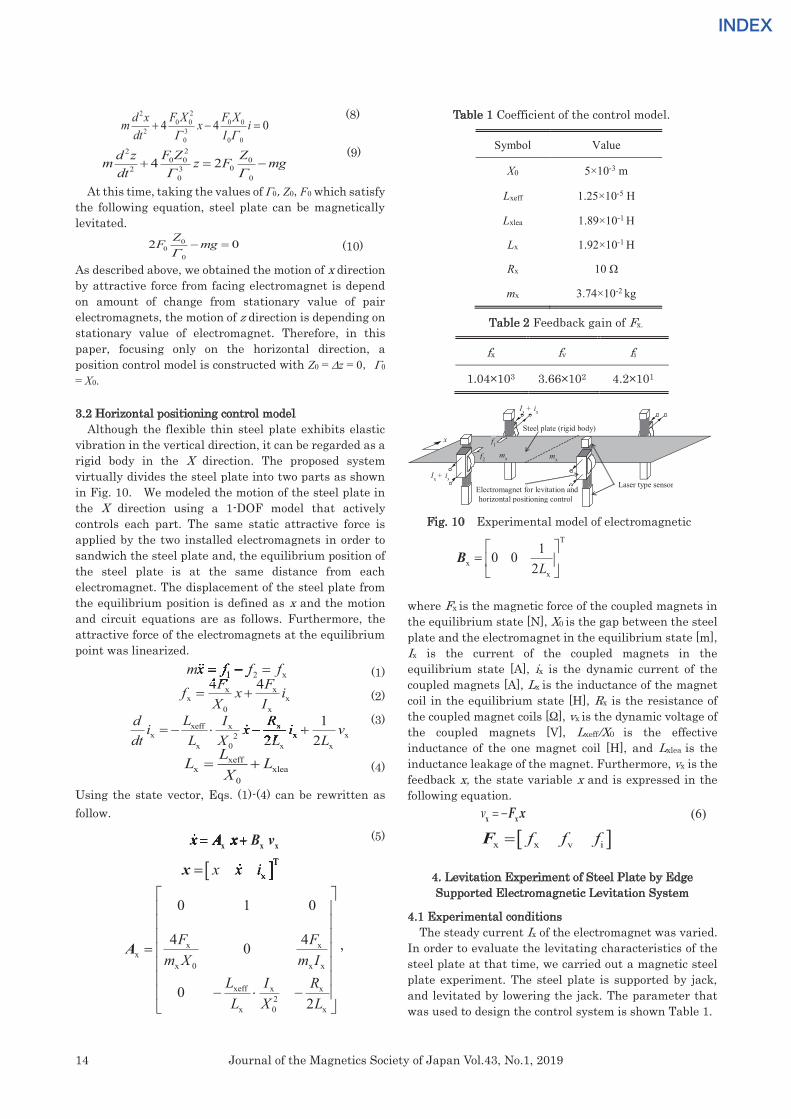
As described above, we obtained the motion of x direction by attractive force from facing electromagnet is depend on amount of change from stationary value of pair electromagnets, the motion of z direction is depending on stationary value of electromagnet. Therefore, in this paper, focusing only on the horizontal direction, a position control model is constructed with Z0 = z = 0,0 = X0. 3.2 Horizontal positioning control model Although the flexible thin steel plate exhibits elastic vibration in the vertical direction, it can be regarded as a rigid body in the X direction. The proposed system virtually divides the steel plate into two parts as shown in Fig. 10. We modeled the motion of the steel plate in the X direction using a 1-DOF model that actively controls each part. The same static attractive force is applied by the two installed electromagnets in order to sandwich the steel plate and, the equilibrium position of the steel plate is at the same distance from each electromagnet. The displacement of the steel plate from the equilibrium position is defined as x and the motion and circuit equations are as follows. Furthermore, the attractive force of the electromagnets at the equilibrium point was linearized.
(1)
(2)
(3)
(4)
Using the state vector, Eqs. (1)-(4) can be rewritten as follow.
(5)
Txx x i=x Txx x ixx x ix
x xx
x 0 x x
xeff x x2
x 0 x
0 1 0
4 40
02
F Fm X m I
L I RL X L
=
− −
A ,
Table 1 Coefficient of the control model.
T
xx
10 02L
=
B
where Fx is the magnetic force of the coupled magnets in the equilibrium state [N], X0 is the gap between the steel plate and the electromagnet in the equilibrium state [m], Ix is the current of the coupled magnets in the equilibrium state [A], ix is the dynamic current of the coupled magnets [A], Lx is the inductance of the magnet coil in the equilibrium state [H], Rx is the resistance of the coupled magnet coils [Ω], vx is the dynamic voltage of the coupled magnets [V], Lxeff/X0 is the effective inductance of the one magnet coil [H], and Lxlea is the inductance leakage of the magnet. Furthermore, vx is the feedback x, the state variable x and is expressed in the following equation.
v = −F xx x (6)
x x v if f f=F
4. Levitation Experiment of Steel Plate by Edge Supported Electromagnetic Levitation System
4.1 Experimental conditions
The steady current Ix of the electromagnet was varied. In order to evaluate the levitating characteristics of the steel plate at that time, we carried out a magnetic steel plate experiment. The steel plate is supported by jack, and levitated by lowering the jack. The parameter that was used to design the control system is shown Table 1.
Symbol Value
X0 5×10⁻³ m
Lxeff 1.25×10⁻⁵ H
Lxlea 1.89×10⁻¹ H
Lx 1.92×10⁻¹ H
Rx 10 Ω
mx 3.74×10⁻² kg
fx fv fi
1.04×10³ 3.66×10² 4.2×101
xeffx xlea
0
LL LX
= +
x xx x
0 x
4 4F Ff x iX I
= +
xeff x xx x x2
x 0 x x
12 2
L I Rd i x i vdt L X L L
= − − +I Ri x i vx xi x i vx xI Ri x i vI Rx xI Rx xi x i vx xI Rx x
x x xx x xi x i vx x xdt L X L Lx x xdt L X L Lx x x2 2dt L X L L2 2x x x2 2x x xdt L X L Lx x x2 2x x xi x i v= − − +i x i vi x i v= − − +i x i vx xi x i vx x= − − +x xi x i vx xx x xi x i vx x x= − − +x x xi x i vx x x
= +x A x B vx A x B v= +x A x B v= +x x x
Table 2 Feedback gain of Fx.
Fig. 10 Experimental model of electromagnetic suspension force.
1 2 xmx f f f= − =4 44 4F F4 4
1 2 xmx f f f1 2 xmx f f f1 2 xmx f f f= − =mx f f f
f1
mx
x
Ix + ix
Steel plate (rigid body)
Electromagnet for levitation and horizontal positioning control
Laser type sensorIx + ix
mxf2
15Journal of the Magnetics Society of Japan Vol.43, No.1, 2019
INDEXINDEX
(a) Ix = 0.9 A (b) Ix = 1.0 A (c) Ix = 1.1 A (d) Ix = 1.2 A
Fig. 11 Time histories of the horizontal displacement x of the steel plate.
(a) Ix = 0.9 A (b) Ix = 1.0 A (c) Ix = 1.1 A (d) Ix = 1.2 A
Fig. 12 Time histories of the vertical displacement z of the steel plate.
Furthermore, we searched for the feedback gain Fx of equation (6), which was determined by trial and error and is shown in Table 2. For the experimental conditions, the range of steady current was changed to Ix = 0.9 ~1.2 A.
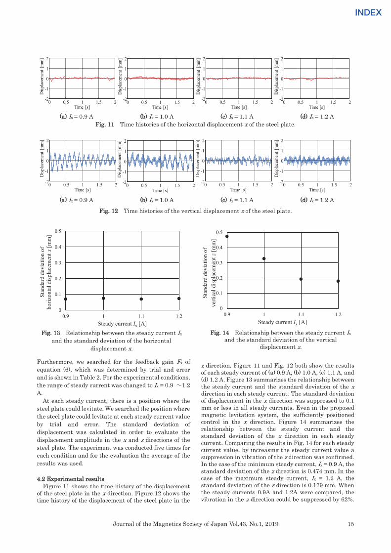
At each steady current, there is a position where the steel plate could levitate. We searched the position where the steel plate could levitate at each steady current value by trial and error. The standard deviation of displacement was calculated in order to evaluate the displacement amplitude in the x and z directions of the steel plate. The experiment was conducted five times for each condition and for the evaluation the average of the results was used. 4.2 Experimental results Figure 11 shows the time history of the displacement of the steel plate in the x direction. Figure 12 shows the time history of the displacement of the steel plate in the
z direction. Figure 11 and Fig. 12 both show the results of each steady current of (a) 0.9 A, (b) 1.0 A, (c) 1.1 A, and (d) 1.2 A. Figure 13 summarizes the relationship between the steady current and the standard deviation of the x direction in each steady current. The standard deviation of displacement in the x direction was suppressed to 0.1 mm or less in all steady currents. Even in the proposed magnetic levitation system, the sufficiently positioned control in the x direction. Figure 14 summarizes the relationship between the steady current and the standard deviation of the z direction in each steady current. Comparing the results in Fig. 14 for each steady current value, by increasing the steady current value a suppression in vibration of the z direction was confirmed. In the case of the minimum steady current, Ix = 0.9 A, the standard deviation of the z direction is 0.474 mm. In the case of the maximum steady current, Ix = 1.2 A, the standard deviation of the z direction is 0.179 mm. When the steady currents 0.9A and 1.2A were compared, the vibration in the z direction could be suppressed by 62%.
0 0.5 1 1.5 2-2
-1
0
1
2
Time [s]
Disp
lacem
ent [
mm
]
0 0.5 1 1.5 2-2
-1
0
1
2
Disp
lacem
ent [
mm
]
Time [s]0 0.5 1 1.5 2-2
-1
0
1
2
Time [s]
Disp
lacem
ent [
mm
]
0 0.5 1 1.5 2-2
-1
0
1
2
Time [s]
Disp
lacem
ent [
mm
]
0 0.5 1 1.5 2-2
-1
0
1
2
Time [s]
Disp
lacem
ent [
mm
]
0 0.5 1 1.5 2-2
-1
0
1
2
Time [s]
Disp
lacem
ent [
mm
]
0 0.5 1 1.5 2-2
-1
0
1
2
Time [s]D
isplac
emen
t [m
m]
0 0.5 1 1.5 2-2
-1
0
1
2
Time [s]
Disp
lacem
ent [
mm
]
Fig. 13 Relationship between the steady current Ix and the standard deviation of the horizontal
displacement x.
Fig. 14 Relationship between the steady current Ix and the standard deviation of the vertical
displacement z.
0
0.1
0.2
0.3
0.4
0.5
0.9 1 1.1 1.2
Stan
dard
dev
iatio
n of
verti
cal d
ispl
acem
entz
[mm
]
Steady current Ix [A]
0
0.1
0.2
0.3
0.4
0.5
0.9 1 1.1 1.2
Stan
dard
dev
iatio
n of
ho
rizon
tal d
ispl
acem
ent x
[mm
]
Steady current Ix [A]
16 Journal of the Magnetics Society of Japan Vol.43, No.1, 2019
INDEXINDEX
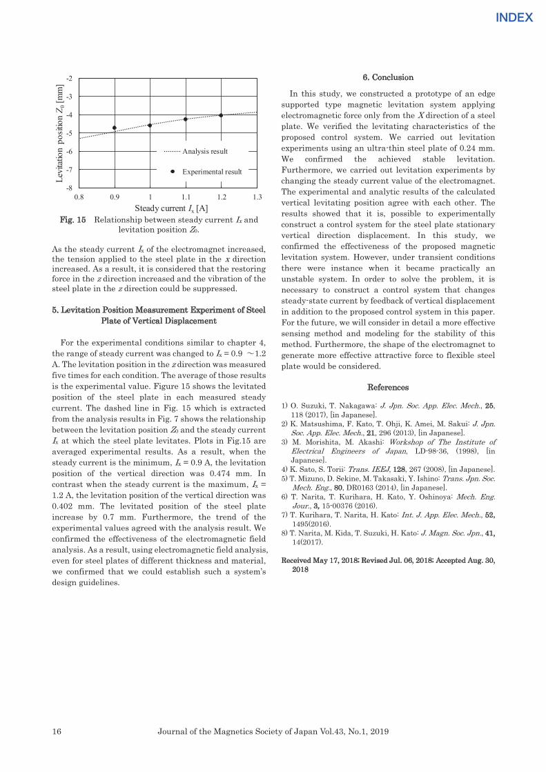
Fig. 15 Relationship between steady current Ix and
levitation position Z0. As the steady current Ix of the electromagnet increased, the tension applied to the steel plate in the x direction increased. As a result, it is considered that the restoring force in the z direction increased and the vibration of the steel plate in the z direction could be suppressed. 5. Levitation Position Measurement Experiment of Steel
Plate of Vertical Displacement For the experimental conditions similar to chapter 4, the range of steady current was changed to Ix = 0.9 ~1.2 A. The levitation position in the z direction was measured five times for each condition. The average of those results is the experimental value. Figure 15 shows the levitated position of the steel plate in each measured steady current. The dashed line in Fig. 15 which is extracted from the analysis results in Fig. 7 shows the relationship between the levitation position Z0 and the steady current Ix at which the steel plate levitates. Plots in Fig.15 are averaged experimental results. As a result, when the steady current is the minimum, Ix = 0.9 A, the levitation position of the vertical direction was 0.474 mm. In contrast when the steady current is the maximum, Ix = 1.2 A, the levitation position of the vertical direction was 0.402 mm. The levitated position of the steel plate increase by 0.7 mm. Furthermore, the trend of the experimental values agreed with the analysis result. We confirmed the effectiveness of the electromagnetic field analysis. As a result, using electromagnetic field analysis, even for steel plates of different thickness and material, we confirmed that we could establish such a system’s design guidelines.
6. Conclusion
In this study, we constructed a prototype of an edge supported type magnetic levitation system applying electromagnetic force only from the X direction of a steel plate. We verified the levitating characteristics of the proposed control system. We carried out levitation experiments using an ultra-thin steel plate of 0.24 mm. We confirmed the achieved stable levitation. Furthermore, we carried out levitation experiments by changing the steady current value of the electromagnet. The experimental and analytic results of the calculated vertical levitating position agree with each other. The results showed that it is, possible to experimentally construct a control system for the steel plate stationary vertical direction displacement. In this study, we confirmed the effectiveness of the proposed magnetic levitation system. However, under transient conditions there were instance when it became practically an unstable system. In order to solve the problem, it is necessary to construct a control system that changes steady-state current by feedback of vertical displacement in addition to the proposed control system in this paper. For the future, we will consider in detail a more effective sensing method and modeling for the stability of this method. Furthermore, the shape of the electromagnet to generate more effective attractive force to flexible steel plate would be considered.
References 1) O. Suzuki, T. Nakagawa: J. Jpn. Soc. App. Elec. Mech., 25,
118 (2017), [in Japanese]. 2) K. Matsushima, F. Kato, T. Ohji, K. Amei, M. Sakui: J. Jpn.
Soc. App. Elec. Mech., 21, 296 (2013), [in Japanese]. 3) M. Morishita, M. Akashi: Workshop of The Institute of
Electrical Engineers of Japan, LD-98-36, (1998), [in Japanese].
4) K. Sato, S. Torii: Trans. IEEJ, 128, 267 (2008), [in Japanese]. 5) T. Mizuno, D. Sekine, M. Takasaki, Y. Ishino: Trans. Jpn. Soc.
Mech. Eng., 80, DR0163 (2014), [in Japanese]. 6) T. Narita, T. Kurihara, H. Kato, Y. Oshinoya: Mech. Eng.
Jour., 3, 15-00376 (2016). 7) T. Kurihara, T. Narita, H. Kato: Int. J. App. Elec. Mech., 52,
1495(2016). 8) T. Narita, M. Kida, T. Suzuki, H. Kato: J. Magn. Soc. Jpn., 41,
14(2017). Received May 17, 2018; Revised Jul. 06, 2018; Accepted Aug. 30,
2018
-8
-7
-6
-5
-4
-3
-2
0.8 0.9 1 1.1 1.2 1.3
Levi
tatio
n po
sitio
n Z 0
[mm
]
Steady current Ix [A]
Analysis result
Experimental result
INDEXINDEX
Editorial Committee Members・Paper Committee Members
K. Kobayashi and T. Ono (Director), T. Kato, K. Koike and T. Taniyama (Secretary)A. Fujita H. Goto H. Hashino S. Honda S. Inui Y. Kanai S. Kasai A. Kikitsu H. Kikuchi T. Kimura T. Kubota K. Miura T. Nagahama H. Naganuma M. Naoe M. Ohtake N. Pham T. SasayamaT. Sato T. Sato K. Sekiguchi M. Sekino T. Shima Y. ShiratsuchiM. Sonehara T. Tanaka S. Yamada K. Yamamoto H. Yuasa
N. Adachi K. Bessho M. Doi T. Doi T. Hasegawa N. InabaS. Isogami K. Kamata H. Kato K. Kato T. Koda S. KokadoY. Kota T. Maki E. Miyashita T. Morita S. Muroga H. NakayamaT. Narita D. Oyama J. Ozeki T. Saito S. Seino K. Tajima M. Takezawa T. Takura M. Tsunoda S. Yabukami T. Yamamoto K. Yamazaki S. Yoshimura
Notice for Photocopying
If you wish to photocopy any work of this publication, you have to get permission from the following organization to which li-censing of copyright clearance is delegated by the copyright owner.
〈All users except those in USA〉 〈Users in USA〉Japan Academic Association for Copyright Clearance, Inc. (JAACC) Copyright Clearance Center, Inc.6–41 Akasaka 9-chome, Minato-ku, Tokyo 107–0052 Japan 222 Rosewood Drive, Danvers, MA01923 USAPhone 81–3–3475–5618 FAX 81–3–3475–5619 E-mail: [email protected] Phone 1–978–750–8400 FAX 1–978–646–8600
編 集 委 員・論 文 委 員
小林宏一郎(理事) 小 野 輝 男 (理事)加 藤 剛 志 (幹事)小 池 邦 博 (幹事)谷 山 智 康 (幹事)乾 成 里 大 竹 充 葛 西 伸 哉 金 井 靖 喜 々 津 哲 菊 池 弘 昭 木 村 崇 窪 田 崇 秀 後 藤 博 樹笹 山 瑛 由 佐 藤 拓 佐 藤 岳 嶋 敏 之 白 土 優 関 口 康 爾 関 野 正 樹 曽 根 原 誠 田 中 哲 郎直 江 正 幸 永 沼 博 長 浜 太 郎 橋 野 早 人 PHAM NAMHAI 藤 田 麻 哉 本 多 周 太 三 浦 健 司山 田 晋 也 山 本 健 一 湯 浅 裕 美
安 達 信 泰 磯 上 慎 二 稲 葉 信 幸 小瀬木淳一 小 山 大 介 加 藤 宏 朗 加 藤 和 夫 鎌 田 清 孝 神 田 哲 典古 門 聡 士 小 田 洋 平 齊 藤 敏 明 清 野 智 史 田 倉 哲 也 竹 澤 昌 晃 田 島 克 文 角 田 匡 清 土 井 達 也土 井 正 晶 中 山 英 俊 成 田 正 敬 長 谷 川 崇 別 所 和 宏 槙 智 仁 宮 下 英 一 室 賀 翔 森 田 孝薮 上 信 山 崎 慶 太 山 本 崇 史 吉 村 哲
複写をされる方へ
本会は下記協会に複写に関する権利委託をしていますので,本誌に掲載された著作物を複写したい方は,同協会より許諾を受けて複写して下さい.但し(社)日本複写権センター(同協会より権利を再委託)と包括複写許諾契約を締結されている企業の社員による社内利用目的の複写はその必要はありません.(社外頒布用の複写は許諾が必要です.)権利委託先:一般社団法人学術著作権協会 〒107–0052 東京都港区赤坂9–6–41 乃木坂ビル 電話(03) 3475–5618 FAX (03) 3475–5619 E-mail: [email protected]なお,著作者の転載・翻訳のような,複写以外の許諾は,学術著作権協会では扱っていませんので,直接本会へご連絡ください.
本誌掲載記事の無断転載を禁じます.
Journal of the Magnetics Society of Japan
Vol. 43 No. 1 Published Jan. 1, 2019by the Magnetics Society of Japan
Tokyo YWCA building Rm207, 1–8–11 Kanda surugadai, Chiyoda-ku, Tokyo 101–0062Tel. +81–3–5281–0106 Fax. +81–3–5281–0107
Printed by JP Corporation Co., Ltd.Sports Plaza building 401, 2–4–3, Shinkamata Ota-ku, Tokyo 144–0054
Advertising agency: Kagaku Gijutsu-sha
発行:(公社)日本磁気学会 101–0062 東京都千代田区神田駿河台 1–8–11 東京YWCA会館 207 号室製作:ジェイピーシー 144–0054 東京都大田区新蒲田 2–4–3 スポーツプラザビル401 Tel.(03)6715–7915広告取扱い:科学技術社 111–0052 東京都台東区柳橋 2–10–8 武田ビル4F Tel. (03) 5809–1132
Copyright Ⓒ2019 by the Magnetics Society of Japan
Vol. 43 No. 1 (通巻第 301 号) 2019 年 1 月 1 日発行