Journal of Sound and Vibration - Pennsylvania State University
18
Comparative methods to assess harmonic response of nonlinear piezoelectric energy harvesters interfaced with AC and DC circuits Chunbo Lan a, c , Lihua Tang a, * , Ryan L. Harne b a Department of Mechanical Engineering, University of Auckland, Auckland, 1010, New Zealand b Department of Mechanical and Aerospace Engineering, The Ohio State University, Columbus, OH 43210, USA c Department of Engineering Mechanics, Northwestern Polytechnical University, Xi'an, 710072, People's Republic of China article info Article history: Received 27 August 2017 Received in revised form 8 November 2017 Accepted 11 November 2017 Keywords: Nonlinear energy harvesting Piezoelectric Monostable AC and DC interface circuits abstract Nonlinear piezoelectric energy harvester (PEH) has been widely investigated during the past few years. Among the majority of these researches, a pure resistive load is used to evaluate power output. To power conventional electronics in practical application, the alternating current (AC) generated by nonlinear PEH needs to be transformed into a direct current (DC) and rectifying circuits are required to interface the device and electronic load. This paper aims at exploring the critical influences of AC and DC interface circuits on nonlinear PEH. As a representative nonlinear PEH, we fabricate and evaluate a monostable PEH in terms of generated power and useful operating bandwidth when it is connected to AC and DC interface circuits. Firstly, the harmonic balance analysis and equivalent circuit representation method are utilized to tackle the modeling of nonlinear energy harvesters connected to AC and DC interface circuits. The performances of the monostable PEH connected to these interface circuits are then analyzed and compared, focusing on the influences of the varying load, excitation and electromechanical coupling strength on the nonlinear dynamics, bandwidth and harvested power. Subsequently, the behaviors of the monostable PEH with AC and DC interface circuits are verified by experiment. Results indicate that both AC and DC interface circuits have a peculiar influence on the power peak shifting and operational bandwidth of the monostable PEH, which is quite different from that on the linear PEH. © 2018 Elsevier Ltd. All rights reserved. 1. Introduction Recently, researchers have been searching alternatives to harvest vibration energy in environment to provide a green power supply for small devices. To enlarge the operational bandwidth and improve the output power, nonlinear dynamics [1e4] have been widely introduced in the piezoelectric energy harvesters (PEH). Nonlinear systems such as Duffing-type PEH have been widely investigated and shown significant improvements in bandwidth and harvested power [5e8]. The main superiority of these nonlinear PEHs as compared to the linear PEH is the existence of high-energy oscillations in a wide frequency bandwidth [9]. When the nonlinear PEH surfs on the high-energy orbits, a huge output power enhancement can be * Corresponding author. E-mail address: [email protected] (L. Tang). Contents lists available at ScienceDirect Journal of Sound and Vibration journal homepage: www.elsevier.com/locate/jsvi https://doi.org/10.1016/j.jsv.2017.11.019 0022-460X/© 2018 Elsevier Ltd. All rights reserved. Journal of Sound and Vibration 421 (2018) 61e78
Transcript of Journal of Sound and Vibration - Pennsylvania State University

Journal of Sound and Vibration 421 (2018) 61e78
Contents lists available at ScienceDirect
Journal of Sound and Vibration
journal homepage: www.elsevier .com/locate/ jsvi
Comparative methods to assess harmonic response ofnonlinear piezoelectric energy harvesters interfaced with ACand DC circuits
Chunbo Lan a, c, Lihua Tang a, *, Ryan L. Harne b
a Department of Mechanical Engineering, University of Auckland, Auckland, 1010, New Zealandb Department of Mechanical and Aerospace Engineering, The Ohio State University, Columbus, OH 43210, USAc Department of Engineering Mechanics, Northwestern Polytechnical University, Xi'an, 710072, People's Republic of China
a r t i c l e i n f o
Article history:Received 27 August 2017Received in revised form 8 November 2017Accepted 11 November 2017
Keywords:Nonlinear energy harvestingPiezoelectricMonostableAC and DC interface circuits
* Corresponding author.E-mail address: [email protected] (L. Tang).
https://doi.org/10.1016/j.jsv.2017.11.0190022-460X/© 2018 Elsevier Ltd. All rights reserved.
a b s t r a c t
Nonlinear piezoelectric energy harvester (PEH) has been widely investigated during thepast few years. Among the majority of these researches, a pure resistive load is used toevaluate power output. To power conventional electronics in practical application, thealternating current (AC) generated by nonlinear PEH needs to be transformed into a directcurrent (DC) and rectifying circuits are required to interface the device and electronic load.This paper aims at exploring the critical influences of AC and DC interface circuits onnonlinear PEH. As a representative nonlinear PEH, we fabricate and evaluate a monostablePEH in terms of generated power and useful operating bandwidth when it is connected toAC and DC interface circuits. Firstly, the harmonic balance analysis and equivalent circuitrepresentation method are utilized to tackle the modeling of nonlinear energy harvestersconnected to AC and DC interface circuits. The performances of the monostable PEHconnected to these interface circuits are then analyzed and compared, focusing on theinfluences of the varying load, excitation and electromechanical coupling strength onthe nonlinear dynamics, bandwidth and harvested power. Subsequently, the behaviors ofthe monostable PEH with AC and DC interface circuits are verified by experiment. Resultsindicate that both AC and DC interface circuits have a peculiar influence on the power peakshifting and operational bandwidth of the monostable PEH, which is quite different fromthat on the linear PEH.
© 2018 Elsevier Ltd. All rights reserved.
1. Introduction
Recently, researchers have been searching alternatives to harvest vibration energy in environment to provide a greenpower supply for small devices. To enlarge the operational bandwidth and improve the output power, nonlinear dynamics[1e4] have beenwidely introduced in the piezoelectric energy harvesters (PEH). Nonlinear systems such as Duffing-type PEHhave been widely investigated and shown significant improvements in bandwidth and harvested power [5e8]. The mainsuperiority of these nonlinear PEHs as compared to the linear PEH is the existence of high-energy oscillations in a widefrequency bandwidth [9]. When the nonlinear PEH surfs on the high-energy orbits, a huge output power enhancement can be

C. Lan et al. / Journal of Sound and Vibration 421 (2018) 61e7862
achieved. Similar to these single degree of freedom (SDOF) nonlinear PEHs, the multi-DOF systems were added with themagnetic interaction induced nonlinearity to pursue a wide operational bandwidth recently. Two kinds of 2-DOF nonlinearPEHs have obtained preliminary results [10e15]. One is using the magnetic force to integrate two independent SDOF systems(such as cantilever piezoelectric beams), while the other is adding the magnets forces into a linear 2DOF PEH. Both config-urations can be further designed into monostable [10], bistable [11,12] and even multistable. Results of the first configurationshow that high-energy oscillations around the first and second resonances maintain a much wider operational bandwidththan that in SDOF nonlinear PEHs. Meanwhile, internal resonance andmodal interactions [13,14,16,17] clearly observed in thesecond configurations have attracted great interests due to an energetic saturation vibration and enhanced energy transferbetween modes that promote an exceptional wide-bandwidth harvesting performance.
Alongwith the abundant designs of nonlinear PEHs, the electric circuits for energy conversion and storage also received greatattentions. In application, the alternating current generated by piezoelectric patches needs to be transformed into direct cur-rents. Indeed, standard rectifying circuits (DC interface) are required to interface the PEH and electronic load in practice. Re-searchers have designed advanced nonlinear circuits, such as resistive impedance matching circuit [18] and parallel/series-SSHI(synchronized switch harvesting on inductor) [19,20], to improve the efficiency of energy harvesting. Hence, it is of greatimportance to understand the inherent relations between circuits and the dynamics of linear/nonlinear piezoelectric energyharvesters. Shu and Lien [21] investigated the optimal AC-DC power generation for a linear piezoelectric PEH. The trends invibration, rectified voltage and average power observed in Ref. [25] are indeed very similar to those of AC circuit in Ref. [22]. Asthe resistance increases, there are two power peaks, one is close to the open circuit while the other is close to the short circuitwhen the electromechanical coupling coefficient is strong enough. Rupp et al. [23] developed a computational methodologybased on harmonic balance method for accurate analysis of the interaction between linear piezoelectric PEHs and a nonlinearcircuit with diodes. As the inherent relations between linear PEHs and standard rectifying circuits becoming clear, a few re-searches begin to explore the role of non-rectifying and rectifying circuits on the nonlinear PEHs. Liu et al. [24] evaluated abistable PEH connected to DC and SSHI circuits and observed unique impacts from such advanced circuits upon the powergeneration outputs as compared to that by connecting an AC interface circuit. Yet, the comprehensive understanding of theinfluences of these rectifying circuits on the behaviours of nonlinear piezoelectric energy harvesters are still inadequate. Giventhe sensitivities of nonlinear PEH observed in the studies surveyed above, such as ability or inability to induce the high-energyoscillations, it is critical to identify the roles of the realistic rectifying circuits upon the dynamics of nonlinear PEHs.
Given these unknowns, a preliminary research focusing on the effect of load resistance on the dynamics of monostablePEH has been conducted by authors in Ref. [25]. It is observed in the simulations that the increase of resistancewill result in anexceptional shift of power peak. In this work, we are motivated to further explore the effect of AC and DC interfaces circuits onthe nonlinear dynamics of monostable PEH in a more generic scenario (various load resistances, excitations, electrome-chanical coupling strengths) andmore importantly, ascertain the inherent mechanisms behind these interesting phenomena.First, we conduct harmonic balance analysis and equivalent circuit modeling (ECM) to predict performances of nonlinear PEHwith AC and DC interface circuits. By using these methods, we are interested to figure out how the two circuits affect thenonlinear dynamics and how it in turn affects the performance of monostable PEH. The theoretical and simulation results areexperimentally validated and reveal the similarities and differences in the trend of the resonant power peak shift againstvarious load resistances in AC and DC interfaces and the sensitivity to excitation. Further analysis and simulation also unlockthe influence of electromechanical coupling strength on the power output for both interface circuits.
2. Modeling
The schematic of the nonlinear piezoelectric energy harvester investigated in this paper is shown in Fig. 1. It is made of apiezoelectric bimorph cantilever with a tip mass. The tip mass carries a permanent magnet that interacts with anothermagnet held in the acrylic holder attached to the rig. The threaded acrylic holder is movable, thus the repulsivemagnetic forcebetween these two magnets can be adjusted by tuning the distance between the magnets. When the magnetic force is largeenough to make the cantilever beam buckle, the system turns to be a bistable PEH. Otherwise, it is a monostable or quasi-linear PEH. The governing equations of this kind of nonlinear PEH can be written according to the fundamental, lowest-order mode of dynamic response using
Fig. 1. Schematic of monostable PEH connected to AC or DC interface circuit.

C. Lan et al. / Journal of Sound and Vibration 421 (2018) 61e78 63
Meff €xðtÞ þ Ceff _xðtÞ þ KeffxðtÞ �QVðtÞ þ Fmagnet ¼ �Meff €yðtÞ (1)
IðtÞ þ Cp _VðtÞ þQ _xðtÞ ¼ 0 (2)
where Meff, Ceff and Keff are the effective mass, damping and stiffness respectively. For the cantilever beam of monostableconfiguration, the effective mass and stiffness can take the following forms [26]Meff¼ bMAbLrþMt, Keff¼ (bKEI)/L3, where rAb
and EI are the mass per unit length and bending stiffness of the cantilever beam, respectively, and L is the length of cantileverbeam. bM and bK are coefficients related to the dynamic mode shape and strain distribution of the cantilever beam, and theycan be determined based on the energy conservation principle. The effective damping is then obtained by Ceff¼ 2zunMeff,where z is the damping ratio determined by utilizing the logarithmic decrement method in experimental test; Q is theelectromechanical coupling coefficient; Cp is the clamped capacitance of the piezoelectric transducer; yðtÞ ¼ YsinðutÞÞ andxðtÞ are the displacement of the base and the displacement of the tip mass relative to the base, respectively; VðtÞ is the voltageacross the piezoelectric transducer; IðtÞ is the current flowing into the interface circuit; and Fmagnet is the magnetic force.
This model includes nonlinear restoring force (frommagnets), but assumes a linear electromechanical coupling behaviour.The dipole-dipole magnetic interaction model [27] is frequently used in the literature to describe the repulsive force andpotential energy between two magnets. The potential energy between two magnets is
UðxÞ ¼ tm1m2
2p
�x2 þ D2
��32 (3)
where t ¼ 4p� 10�7 NA�2 is the permeability constant in vacuum; m1 and m2 are the effective magnetic moments of themagnetic dipoles. In this study, m1¼m2¼m¼ 0.164 Am2. D is the center-to-center distance between two magnets. Hence,D¼D0 þ D, where D0 is the surface-to-surface distance between magnets and D¼ 3mm is the thickness of magnet. Themagnetic force can be derived by differentiating Eq. (3) with respect to x,
FmagnetðxÞ ¼ f0x�
x2 þ D2�52
(4)
where f0 ¼ �3tm2=ð2pÞ. For the convenience of harmonic balance analysis in the next sections, Eq. (4) is expanded in a Taylorseries about x¼ 0. By ignoring series terms of order greater than 3, we obtain
FmagnetðxÞ ¼ K1xþ K3x3 (5)
where K1 ¼ f0D�5;K3 ¼ �2:5f0D�7.Moreover, V (t) and I (t) are related in different ways according to the interface circuit property.When a PEH is connected to
a pure resistor RL, the relation between the voltage and current is linear with V (t)¼ I (t) RL. Thus, Eq. (2) can be rewritten as
VðtÞRL
þ Cp _VðtÞ þQ _xðtÞ ¼ 0 (6)
When the PEH is connected to a standard rectifying DC interface circuit, the current balance equations can be derivedbased on the Schockley model by Leadenham [28]. They are
Cp _VðtÞ þQ _xðtÞ þ 2Issinh�VðtÞ2nVT
�exp
��Vf ðtÞ2nVT
�¼ 0 (7)
Cf _V f ðtÞ þ Vf ðtÞ=RL þ 2Is
�1� cosh
�VðtÞ2nVT
�exp
��Vf ðtÞ2nVT
�¼ 0 (8)
where Cf is the capacitance of the filter capacitor; Vf(t) is the output voltage across the filter capacitor (same voltage across theload resistor); I ¼ 1 pA is the saturation current of diode, which is a constant; n¼ 1 is the ideality factor of diode; the thermal
svoltage defined as VT¼ 26mV at room temperature. Thus, Eqs. (1), (7) and (8) constitute the governing equations of themonostable PEH with DC interface circuit.
2.1. Harmonic balance analysis
2.1.1. Monostable PEH with AC interfaceWhen the dynamics of nonlinear energy harvesters connected to an AC interface circuit are considered, a variety of
approximate analytical methods, such as harmonic balance method [29] or method of multiple scales [30], may directly

C. Lan et al. / Journal of Sound and Vibration 421 (2018) 61e7864
predict the power generation for a given nonlinear harvester design and implementation. In this paper, harmonic balancemethod is chosen for theoretical analysis. It has been used in the literature when deriving the approximate steady statesolutions for bistable PEH [29,31], tri-stable PEH [32], and so on. The detailed deviation of monostable PEH's steady solutionsis similar to that of bistable PEH given in Ref. [29]. The frequency-amplitude response is obtained as,
r2
24 � u2Meff þ k0 þ34r2K3 þ
CpðQRLuÞ2�CpRLu
�2 þ 1
!2
þ uCeff þ
Q2RLu�CpRLu
�2 þ 1
!2
35 ¼ f 2 (9)
where r is the displacement amplitude of the monostable PEH; k0 ¼ Keff þ K1; f ¼ MeffA0 is the amplitude of the excitationforce, where A0 ¼ Yu2 is the amplitude of the acceleration. The detailed derivation is shown in the Appendix. To determinethe stability of the physically meaningful solutions obtained from Eq. (9), the method in Ref. [29] is applied.
Additionally, from the derivation, we find that the effect of AC interface circuit can be regarded as equivalent stiffness anddamping,
KAC ¼ ðRLuQÞ2Cp�CpRLu
�2 þ 1; cAC ¼ Q2RL�
CpRLu�2 þ 1
(10)
It is indicated that the equivalent stiffness KAC and equivalent damping cAC induced by the interface circuit depend on theexternal excitation frequency u, the load resistance RL, the capacitance of the piezoelectric element Cp, and the electrome-chanical couplingQ. Interestingly, it is noted that the expressions of KAC and cAC are independent of the vibration systems, thatis, the change of stiffness and damping are the same to linear and monostable PEHs.
2.1.2. Monostable PEH with DC interfaceIn the case of monostable PEH with DC interface circuit, a Newton's method enabled harmonic balance method is utilized
to get the approximate solutions. This method has been successfully applied to identify the effect of piezoelectric materialinduced nonlinearity on the PEH with DC interface circuit [28]. The principle is shown below and derives from the theorydescribed in Ref. [33].
First, it is necessary to describe the system in the state-space form as
_u ¼ f ðt;uÞ (11)
where u is the state vector and defined as
u ¼ ½u1 u2 u3 u4 �T ¼ x _x V Vf�T (12)
Hence, the governing Eqs. (1), (7) and (8) are rearranged into state-space form as8>>>>>>>>>><>>>>>>>>>>:
_u1 ¼ u2
_u2 ¼ �€yðtÞ ��Ceffu2 þ Keffu1 �Qu3 þ K1u1 þ K3u
31
�.Meff
_u3 ¼��Qu2 � 2Issinh
�u3
2nVT
�exp
��u42nVT
���Cp
_u4 ¼�� u4
RL� 2Is
�1� cosh
�u3
2nVT
�exp
��u42nVT
���Cf
(13)
By assuming that Eq. (11) has periodic solutions with period T, the approximate solutions are expressed in term of Fourierseries as
uðtÞ ¼ uðt þ T;uÞ (14)
buðtÞ ¼ aþ AcðtÞ þ BsðtÞ (15)
where a is a constant vector, A and B are constant matrices, and c(t) and s(t) are vectors of cosines and sines of harmonics. The
component form isbuiðtÞ ¼ ai þXMm¼1
½AimcmðtÞ þ BimsmðtÞ� (16)
with indices,

C. Lan et al. / Journal of Sound and Vibration 421 (2018) 61e78 65
m;n 2½1;2;…;M�;�2pmt
� �2pmt
�
cmðtÞ ¼ cosT; smðtÞ ¼ sin
T
whereM is the number of harmonics included in the truncated Fourier series solution. The derivative of u(t) can be written as
_buiðtÞ ¼2pmT
XMm¼1
½ � AimsmðtÞ þ BimcmðtÞ� (17)
Substituting the assumed solution buiðtÞ into the governing equations f(t,u), yields the approximate system,
bfðtÞ ¼ fðt; buðtÞ� (18)
The residual is defined as
rðtÞ ¼ bfðtÞ � _buðtÞ (19)
By utilizing Galerkin method to minimizing the residual, we obtain
1T
ZT0
rðtÞdt ¼ 0;1T
ZT0
rðtÞcT ðtÞdt ¼ 0;1T
ZT0
rðtÞsT ðtÞdt ¼ 0 (20)
Eq. (20) is a system of 2Mþ 1 unknowns that can be solved for the correct a, A and B. Hence the approximate solutions areobtained.
The error minimization procedure steps towards a defined error tolerance by the way of approximating the derivatives ofthe residual and updating a subsequent step with a refined initial guess. The derivative approximation approach used in thisresearch is described in Refs. [28,33].
To seed the initial guess to themodel, an effective methodmust be employed due to the non-uniqueness of dynamic statespossible for the monostable PEH. Here, the closed-form analytical results obtained from a harmonic balance analysis of themonostable PEH coupled to an AC interface circuit are first computed [34]. This analysis requires on the order of millisecondsto compute across the full frequency range of interest. The outputs of such analysis are the mechanical response and ACpiezoelectric voltage response constants. From these data, the corresponding a, A, and B constants are taken to be initialguesses of the mechanical response and piezoelectric voltage response for the monostable PEH interfaced to the DC interfacecircuit. In all cases, due to themonostability of the PEH, the constants a are nill. For the initial guess of the DC rectified voltage,the constants in A and B are nill. On the other hand, the DC voltage term, by definition, has a bias constant a to be initialized.Here, the square root of the sum of squares of the sinusoidal AC piezoelectric voltage constants from the analytical evaluationis taken, and the result is multiplied by 1=
ffiffiffi2
p. This value is consequently the corresponding constant a for the initial guess of
the DC voltage term. For the DC interface circuit, stability is inherent to the output since an analytically derived Jacobian isprovided to the algorithm. The results consequently converge to stable sets of the response variables [28,33].
2.2. Equivalent circuit model
By representing the monostable energy harvester as an equivalent circuit, the performance of the energy harvestingsystem with AC, DC, and even more advanced interface circuits (such as SSHI and SCE) can be evaluated with the help ofmature SPICE electronics simulator (SIMetrix/SIMPLIS Introduction Version is used in this work). This idea has been provedfeasible in the modeling of galloping based aeroelastic energy harvesting with various practical interface circuits, in which,the aerodynamics force is a nonlinear damping force [35,36]. This idea can be extended to study the PEH with structuralnonlinearity subject to base excitation [14,25]. This simulation method will be utilized in the paper to conduct a compre-hensive parametric study and confirm the findings from the theoretical analysis.
According to the analogies between the electrical and mechanical domains, the charge q, inductance L, capacitance C,resistance R, turn ratio of the ideal transformer N and voltage source VS are equivalent to displacement x, mass Meff,compliance 1/Keff, damping Ceff, electromechanical coupling coefficient Q and force F, respectively. In the following experi-ment and simulation, sinusoidal sweep with constant magnitude of acceleration is considered as the input base excitation.The voltage source component representing the base motion is implemented by a linear chirp signal with magnitude ofMeffA0. The nonlinear magnetic force Fmagnet is implemented by a user defined behavioral voltage source, which can bedefined using the voltage across capacitance C as input [14,25],

C. Lan et al. / Journal of Sound and Vibration 421 (2018) 61e7866
VS NL ¼ K1CVC þ K3ðCVCÞ3 (21)
The details in the implementation of a nonlinear behavioral voltage source can be found in Ref. [25].
3. Theoretical and simulation results
This section presents and compares the performances of themonostable PEHwith AC and DC interface circuits. Threemainfactors affecting the power output and dynamics are studied: load resistance, acceleration and electromechanical couplingstrength. The theoretical results are solved by using harmonic balance methods, while the simulation is carried out byequivalent circuit simulation. The preliminary study on the effect of resistance through equivalent circuit simulation andexperiment was presented in our conference paper [25] and a small portion of the results is reused for comparison withtheoretical analysis. In the simulation, the sine frequency sweep is carried out to obtain the frequency-response curves of thenonlinear energy harvester. Throughout the sine sweep, the peak acceleration is controlled at a constant value and the sweeprate in frequency is 0.02 Hz/s. The system parameters used in theoretical analysis and simulation are obtained from exper-imental tests, as listed in Table 1. The magnet distance D0¼ 8.2mm is adjusted to obtain a typical monostable configuration.
3.1. AC interface
3.1.1. Effect of load resistanceThe effect of load resistance on the monostable PEH with AC interface circuit is investigated in this section. The base
acceleration amplitude is 2ms�2. Fig. 2(a) depicts the theoretical results of the output power against load resistance RL. Theunstable theoretical solutions are illustrated by dotted lines. Upward frequency sweep simulation is also performed and thesimulation results are shown in Fig. 2(b). First, both simulation and theory show that the optimal resistance RL is around167 kU. Second, the resonant peak and bandwidth shift with the varying RL is observed. Interestingly, the resonant peak shiftsto the left and then returns to the right with the increase of RL, with the turning point not exactly but very close to the optimalresistance RL¼ 167 kU. These characteristics of the resonant peak shift of the monostable PEH observed in both theory andECM simulation are different from its linear counterpart. In linear PEH, except for the strong electromechanical coupling, theoptimal power will be achieved between the short circuit and open circuit resonant frequencies and the resonant peak willmove all the way to the right with the increase of RL. For the proposed prototype without magnetic force, the short circuit andopen circuit resonant frequencies are measured to be 19.95 Hz and 20.25 Hz, respectively. Thus, the resonant peak of powerwill shift with RL between these two frequencies. Obviously, given the same electromechanical coupling, the varying resis-tance has much more significant influence on the dynamics of monostable PEH than that on the linear PEH in terms ofresonant peak shift and thus the associated bandwidth.
This phenomenon of resonant peak shift with the varying resistance can be explained from the view of equivalent stiffnessand damping induced by AC interface circuit. The AC interface circuit induced equivalent stiffness KAC and damping cAC can becalculated by equation (10). The surfaces in Fig. 3(a) and (b) are the equivalent stiffness and damping respectively. The solidline with circles indicates the resonant peaks with various resistance and frequency. From Fig. 3, we note that with the in-crease of resistance, KAC increases very slowly with RL first, and then increases quickly, and finally reaches a maximum value(open circuit condition). While, cAC starts to increase with RL first, and then reaches the maximum and decreases (to zeroeventually though not shown on Fig. 3(b)). In the open-circuit and short-circuit conditions, the AC circuit does not produceany equivalent damping to the system. The combination of these changes of KAC and cAC provides the trends of peak shift:when the resistance is very small, the effect of circuit-induced damping is predominant, which leads to the decrease of vi-bration, reduced nonlinear behaviour and thus the peak of power achieved at a lower frequency and a decrease of bandwidth.As the resistance increases and becomes large enough, the effect of circuit-induced stiffness becomes predominant. Thepower peak will shift to a higher frequency due to the increase of the total stiffness of themonostable PEH, though the circuit-induced damping may still increase. In this case, the main effect of circuit-induced damping is decreasing the magnitude ofoutput power rather than frequency shift. Obviously, there is a trade-off between optimal power and operational bandwidthdue to the combined effects of KAC and cAC. The resistance for the maximum power and wide operational bandwidth shouldcompromise.
Table 1Parameters obtained from experiment.
Parameters Symbol Value
Effective mass Meff 0.0082 kgEffective stiffness Keff 138.6 Nm�1
Damping ratio z 0.016Effective damping Ceff 0.0354 Nsm�1
Electromechanical coupling coefficient Q 599 mNV�1
Capacitance of piezoelectric transducer Cp 87 nFFilter capacitance Cf 4.7 mF

Fig. 2. Output powers of theory and ECM with AC interface circuit for weak electromechanical coupling (Q¼ 599 mN/V, A0¼ 2.0ms�2). (a) theory; (b) ECM [25].
Fig. 3. (a) Equivalent stiffness KAC and (b) equivalent damping cAC induced by weak electromechanical coupling (Q¼ 599 mN/V, A0¼ 2.0ms�2).
C. Lan et al. / Journal of Sound and Vibration 421 (2018) 61e78 67

Fig. 4. Output powers of theory and ECM with AC interface circuit for different accelerations (Q¼ 599 mN/V, RL¼ 167 kU).
C. Lan et al. / Journal of Sound and Vibration 421 (2018) 61e7868
3.1.2. Effect of excitationFig. 4 gives the output power of the monostable PEH under different accelerations. The resistance used in the analysis,
RL¼ 167 kU is the optimal resistance obtained from the previous section. The base accelerations are varied: A0¼1ms�2,2ms�2, 3ms�2, 4ms�2. In Fig. 4, both theoretical and ECM simulation agree quite well, showing that the bandwidth andresonant peak will increase with the increase of excitation. Specifically, when the excitation is very low, such as A0¼1ms�2,there is no jumping phenomenon and no region with coexisting responses. As the acceleration increases, the region ofcoexisting responses becomes wider and the power peak increases accordingly. Hence, it is concluded that under strongexcitation, the monostable PEH with AC interface possesses the capability of broadband energy harvesting.
3.1.3. Effect of electromechanical coupling strengthIn section 3.1.1, the effect of resistance on the monostable PEH with a weak electromechanical coupling coefficient is
analyzed. Since the coupling coefficient can largely affect the performance of AC interface circuit, a much strong couplingcoefficient Q¼ 2000 mN/V is chosen in this section to make a comparative study. The acceleration is kept at A0¼ 2ms�2 andthe varying resistances are listed in Table 2.
Fig. 5(a) and (b) depict the theoretical prediction and ECM simulation (upward sweep) result of output powers of ACinterface circuit against RL, respectively. The unstable theoretical solutions are illustrated by dotted lines. First, both simu-lation and theoretical results show that there are two optimal resistances around 10 kU and 1500 kU. One is close to the shortcircuit condition and the other is close to the open circuit condition. Second, when the resistance RL increases from 1 kU to10 kU, the resonant peak of the monostable PEH shifts to the left and the region of coexisting responses becomes narrowgradually. It is noted that when RL increases to 15 kU, the region of coexisting responses disappears (i.e., no jumping), whilethe resonance peak still keeps shifting to the left when RL increases from 10 kU to 30 kU. Subsequently, when RL continues toincrease, the resonant peak turns to shift to the right and the power peak reaches theminimumvaluewhen RL¼ 130 kU. Afterthat, the increase of RL leads to the increase of both resonant peak and frequency until RL reaches the second optimalresistance around 1500 kU. Finally, when RL further increases and exceeds 1500 kU, the resonant peak starts to decrease butkeeps shifting to the right. Interestingly, it is found that the region of coexisting responses (jumping phenomenon) returnswhen RL goes beyond 2500 kU.
To explain this evolution, the equivalent damping cAC and stiffness KAC with this strong electromechanical coupling co-efficient are calculated and shown in Fig. 6. The surfaces in Fig. 6(a) and (b) stand for the KAC and cAC respectively. The dashedcurves with circles represent the resonance peaks at different frequencies and resistances. It is found that, when RL increasesfrom 1 kU to about 500 kU, the equivalent damping and stiffness increase. cAC increases sharply while KAC increases verygently. With the further increase of resistance, cAC starts to decrease while KAC keeps increasing. When the resistance is closeto open circuit, the circuit-induced equivalent damping is close to zero and the circuit-induced equivalent stiffness reachessaturation. As a result, when RL is small and close to short-circuit, the increase of resistance mainly leads to the resonant peakshift to lower frequency due to the sharply increased damping, reduced vibrating response and less nonlinear behaviour. Afterthe jumping phenomenon disappears, the increase of cAC mainly reduces the power of resonant peak. Although the increase
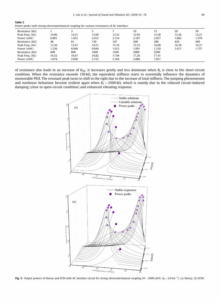
Table 2Power peaks with strong electromechanical coupling for various resistances of AC interface.
Resistance (kU) 1 3 5 7 10 15 20 30Peak Freq. (Hz) 14.96 14.21 13.69 13.32 12.95 12.58 12.36 12.21Power (mW) 0.801 1.652 2.012 2.154 2.187 2.057 1.882 1.579Resistance (kU) 48 81 130 167 200 286 429 500Peak Freq. (Hz) 12.36 13.47 14.51 15.18 15.55 16.00 16.30 16.37Power (mW) 1.236 0.949 0.944 1.012 1.091 1.310 1.617 1.737Resistance (kU) 600 800 1000 1500 2000 2500Peak Freq. (Hz) 16.52 16.67 16.82 17.04 17.26 17.41Power (mW) 1.874 2.058 2.153 2.184 2.086 1.951
C. Lan et al. / Journal of Sound and Vibration 421 (2018) 61e78 69
of resistance also leads to an increase of KAC, it increases gently and less dominant when RL is close to the short-circuitcondition. When the resistance exceeds 130 kU, the equivalent stiffness starts to essentially influence the dynamics ofmonostable PEH. The resonant peak turns to shift to the right due to the increase of total stiffness. The jumping phenomenonand nonlinear behaviour become evident again when RL¼ 2500 kU, which is mainly due to the reduced circuit-induceddamping (close to open-circuit condition) and enhanced vibrating response.
Fig. 5. Output powers of theory and ECM with AC interface circuit for strong electromechanical coupling (Q¼ 2000 mN/V, A0¼ 2.0ms�2). (a) theory; (b) ECM.

Fig. 6. (a) Equivalent stiffness KAC and (b) equivalent damping cAC induced by strong electromechanical coupling (Q¼ 2000 mN/V, A0¼ 2.0ms�2).
C. Lan et al. / Journal of Sound and Vibration 421 (2018) 61e7870
To summarize the above discussion, two optimal power peaks are obtained in the strong electromechanical coupling con-dition, contrasting the only one power peak in the weak coupling condition. One is close to the short circuit, and the other closeto the open circuit. As compared to the linear PEH, the monostable PEH has much complex characteristics of resonant peak shiftand operation bandwidth variance. For themonostable PEH, the high-energy large-amplitude oscillation ismore sensitive to theequivalent damping than stiffness when the resistance is very small. The equivalent damping induced by AC interface circuit willremarkably shrink the range of the useful bandwidth (peak shifts to the left). The continuous increase of the resistance will thenenable the equivalent stiffness to dominate the shift of the resonant peak, which is similar to the behaviour of linear energyharvester. All the results of theory and ECM simulation are very consistent both qualitatively and quantitatively.
3.2. DC interface
In this section, the effects of DC interface circuit on the performance of monostable PEH are investigated and comparedwith that of AC interface circuit in terms of resistance, acceleration and electromechanical coupling coefficient to identify thesimilarities and differences between these two interfaces.
3.2.1. Effect of load resistanceFig. 7 depicts the output power of the monostable PEH with varying resistance RL in the DC interface circuit. As afore-
mentioned, for the DC interface circuit, stability is inherent to the output since an analytically derived Jacobian is provided tothe algorithm. The results only consequently converge to stable responses. First, both theoretical prediction and ECMsimulation (upward sweep) result indicate that, the DC power outputs (computed according to V2/RL) are reduced but with ahigher optimal resistance RL¼ 200 kU, compared to the results with AC interface circuit (Fig. 2). Second, the resonant peakshifts to the left and then returns to the right with the increase of RL, with the turning point close to RL¼ 200 kU. Theseobservations are similar to those of AC interface circuit. In addition, though the shift of the resonant peak with the DCinterface circuit is less than that with the AC interface circuit, it is still more noticeable than the linear PEH. Moreover, thesmall discrepancy between theory and ECM simulations is the ripples in the DC voltage in the ECM simulation rather thanideal steady-state results. The ripples can be reduced in simulation by using a large Cf. However, Cf cannot be too large sincewe would like the harvester to reach quasi-steady-state very quickly, which is dependent on the time constant CfRL. While in

Fig. 7. Output powers of theory and ECM with DC interface circuit for weak electromechanical coupling (Q¼ 599 mN/V, A0¼ 2.0ms�2). (a) theory; (b) ECM [25].
C. Lan et al. / Journal of Sound and Vibration 421 (2018) 61e78 71
the approximate solutions based on the harmonic balance analysis, no ripple is expected as we assume harmonic solution inthe steady state with a correspondingly large Cf. Fortunately, despite the existence of ripples in the ECM simulation, they donot affect the main features of the responses, such as peak shift and bandwidth. From Fig. 7, we conclude that for themonostable PEH with DC interface circuit, the trade-off is still required between maximizing the power and bandwidth,though the sacrifice of bandwidth is less than that in the case of AC interface circuit.
3.2.2. Effect of excitationFig. 8 presents the output power of the monostable PEH with the DC interface circuit under various accelerations:
A0¼1ms�2, 2ms�2, 3ms�2, 4ms�2. The resistance used here RL¼ 200 kU is the optimal resistance obtained from the previoussection. Both the theoretical and ECM results show that the bandwidth and resonant peak will increase due to the increase ofexcitation. The characteristics of DC interface circuit are similar to that of AC interface circuit. First, when the acceleration in-creases, the high-energy large-amplitude oscillation is obtained in a much wider frequency bandwidth. Second, the outputpower of high-energy oscillation benefits very few from the increase of acceleration level. For instance, at f¼ 15Hz, the outputpower with A0¼ 3ms�2 are very close to that with A0¼ 4ms�2. For a certain acceleration, the power output with DC interfacecircuit is much lower than that with AC interface circuit. For example, when A0¼ 4ms�2, the generated power of DC interfacecircuit is 3.253mW while that of AC interface circuit is 7.755mW, that is, 58.05% less. Meanwhile, in terms of the region ofcoexisting responses, it is Df¼ 3.514 HZ (from 14.288 HZ to 17.802 HZ) for the DC interface circuit, while it is Df¼ 2.7326 HZ(from 14.418 HZ to 17.151 HZ) for the AC interface circuit. Consequently, for a certain resistance, the AC interface circuitmay havea larger output power while the DC interface circuit maintains a wider bandwidth of high-energy oscillations. The decrease ofoutput powerwhenmonostable PEH is connected to DC interface circuit ismainly due to the fact that energy transfer stops if thevoltage V across the piezoelectric transducer is lower than the DC voltage Vf in a certain duration of one oscillation period, whichis similar to the linear PEH case. Since it has been proven in Ref. [37] that the rectifying circuit can be treated by impendence

Fig. 8. Output powers of theory and ECM with DC interface circuit for different accelerations (Q¼ 599 mN/V, RL¼ 200 kU).
C. Lan et al. / Journal of Sound and Vibration 421 (2018) 61e7872
analysis, these differences between AC and DC interface circuits can be further explained by the effect of effective resistance onmonostable PEH. When the resistance is larger than the optimal resistance, the increase of RL will result in a decrease of outputpower and awider bandwidth of high-energy oscillation. The less power extracted fromDC interface circuit, in turn, induces lessequivalent damping and gives rise to a larger vibrating response and more evident nonlinear behaviour (wider region ofcoexisting responses) as compared to AC interface circuit.
Though the analytical results agree quite well with the ECM simulations, discrepancy still exists. The main discrepancy isthat the resonant peak of ECM simulation is a bit shifted as compared to that of analytical results. This discrepancy resultsfrom the assumption in theoretical analysis. In the theoretical analysis, we assume steady state periodic response when wederive the solution. However, in simulation, though we use a slow frequency sweep rate (0.02 Hz/s), the response is close tobut still transient rather than exact steady state response. This will be a bit worse in DC interface circuit case because we havenot only transients in dynamic response but also transients in electrical response. The electrical output takes time to reachsteady state that depends on the time constant of the interface circuit (load resistor and filter capacitor). A small filtercapacitor will ensure to reach quasi-steady state but end up with ripples in DC voltage (for example, Fig. 7(b)), while a largefilter capacitor will remove ripples but take a longer time to reach steady state. This, combinedwith the transient in dynamics,makes the delay in jumping (a minor difference in resonant peak) in Fig. 8. In this work, we choose such a capacitor tocompromise: relatively small ripples and minor delay in jumping.
3.2.3. Effect of electromechanical coupling strengthThe electromechanical coupling coefficient is increased to Q¼ 2000 mN/V to explore the effect of strong coupling on the
performance of the monostable PEHwith DC interface circuit. Fig. 9 shows the output power with varying resistance RL (listedin Table 3) from theoretical prediction and ECM simulation (upward sweep). Similarities between AC and DC interface circuitsare noted in Fig. 9. First, when RL increases from 1 kU to 10 kU, the bandwidth of high-energy large-amplitude oscillationdecreases remarkably, accompanied with the increase of peak power and shift to the lower frequency. Second, when RLincreases from 15 kU to 130 kU, the resonant peak decreases gradually and the region of coexisting responses and jumpingphenomenon disappear. Subsequently, when RL further increase to 2500 kU, the resonant peak reaches second peak atRL¼ 2000 kU. Similar to the AC interface circuit, when RL is 2500 kU, the jump phenomenon returns in the theoretical results.Another similarity between the effect of AC and DC interface circuits is that the first peak (RL¼ 10 kU) is close to short circuit,while the second peak (RL¼ 2000 kU) is close to open circuit. The main difference by using these two different interfacecircuits is the output power. By comparing Figs. 5 and 9, it is noted that the maximum output power of AC circuit is 2.19mWwhile that of DC circuit is about 1.09mW.
4. Experimental validation
Experiments are conducted to confirm the conclusions in section 3. Since the coupling strength could not be altered afterprototyping the device, experiment is not ready to confirm the effect of strong electromechanical coupling. The nonlinear
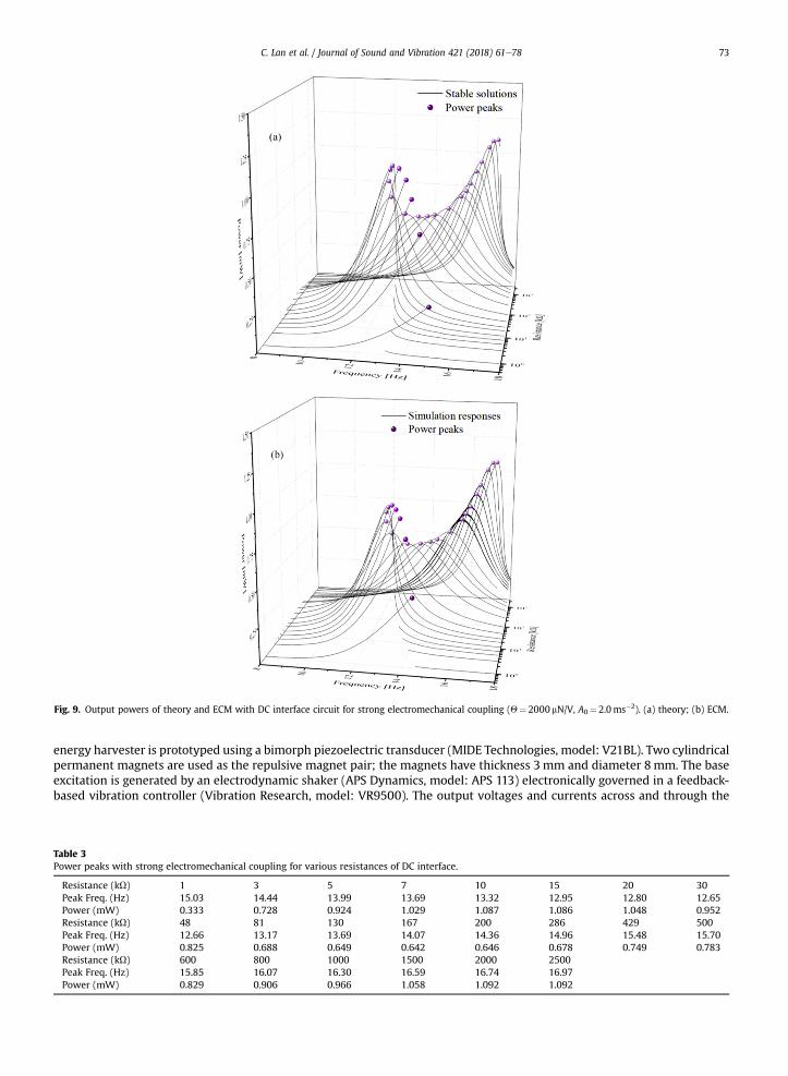
Fig. 9. Output powers of theory and ECM with DC interface circuit for strong electromechanical coupling (Q¼ 2000 mN/V, A0¼ 2.0ms�2). (a) theory; (b) ECM.
C. Lan et al. / Journal of Sound and Vibration 421 (2018) 61e78 73
energy harvester is prototyped using a bimorph piezoelectric transducer (MIDE Technologies, model: V21BL). Two cylindricalpermanent magnets are used as the repulsive magnet pair; the magnets have thickness 3mm and diameter 8mm. The baseexcitation is generated by an electrodynamic shaker (APS Dynamics, model: APS 113) electronically governed in a feedback-based vibration controller (Vibration Research, model: VR9500). The output voltages and currents across and through the
Table 3Power peaks with strong electromechanical coupling for various resistances of DC interface.
Resistance (kU) 1 3 5 7 10 15 20 30Peak Freq. (Hz) 15.03 14.44 13.99 13.69 13.32 12.95 12.80 12.65Power (mW) 0.333 0.728 0.924 1.029 1.087 1.086 1.048 0.952Resistance (kU) 48 81 130 167 200 286 429 500Peak Freq. (Hz) 12.66 13.17 13.69 14.07 14.36 14.96 15.48 15.70Power (mW) 0.825 0.688 0.649 0.642 0.646 0.678 0.749 0.783Resistance (kU) 600 800 1000 1500 2000 2500Peak Freq. (Hz) 15.85 16.07 16.30 16.59 16.74 16.97Power (mW) 0.829 0.906 0.966 1.058 1.092 1.092

C. Lan et al. / Journal of Sound and Vibration 421 (2018) 61e7874
load resistance are acquired by NI 9229 and NI 9203 DAQ modules. The details of parameter identification can be found inRef. [25]. With these parameters and considering the electrical-mechanical equivalence, circuit simulation parameters areidentified.
4.1. AC interface
4.1.1. Effect of load resistanceThe power output against varying resistive loads RL with AC interface circuit is shown in Fig. 10. These results are adopted
from Ref. [25] for comparison with theoretical analysis as well as ECM simulation. Slow upward sweeps are performed withthe same excitation as theoretical analysis. Though the magnitude of power estimated from theory and ECM simulation is abit higher than that in the experiment, the trend is the same: the power peak first shifts to the left when RL increases from48 kU and reaches the maximum at RL¼ 167 kU. With the further increase of RL, the power peak turns to the high frequencywith a loss in power output. The experimental results confirm the theoretical and ECM observation that given the sameelectromechanical coupling, the varying resistance of AC interface circuit has much more significant influence on the dy-namics of the monostable PEH than that on the linear PEH in terms of resonant peak shift and thus the associated bandwidth.
4.1.2. Effect of excitationFig. 11 indicates the upward sweep responses of the monostable PEH with varying accelerations when connected with AC
interface circuit. The accelerations chosen are 1ms�2, 2ms�2, 3ms�2 and 4ms�2, same as those in theoretical analysis andECM simulation. It is noted that the operational bandwidth of the monostable PEH largely increases with the increase ofexcitation. The jumping frequencies in these sweeps are 10.2 Hz, 13.05 Hz, 15.2 Hz and 16.9 Hz respectively, which is close to
Fig. 10. Output powers of experiment with AC interface circuit for weak electromechanical coupling coefficient (Q¼ 599 mN/V, A0¼ 2.0ms�2) [25].
Fig. 11. Output powers of experiment with AC interface circuit for different accelerations (Q¼ 599 mN/V, RL¼ 167 kU).
C. Lan et al. / Journal of Sound and Vibration 421 (2018) 61e78 75
the theory and ECM simulations. Meanwhile, by comparing the output power of the high-energy oscillations under differentexcitations, it is found that the increase of excitation gives minor improvement in output power, while it does enlarge thebandwidth dramatically. The main characteristics in the experiment quantitatively agree with the simulation and theoreticalanalysis, though discrepancies still exist. For instance, under low excitation of A0¼1ms�2, the experimental response showsthe jumping phenomenon, which is not found in the simulation.
4.2. DC interface
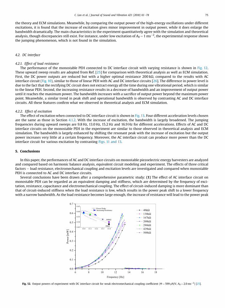
4.2.1. Effect of load resistanceThe performance of the monostable PEH connected to DC interface circuit with varying resistance is shown in Fig. 12.
These upward sweep results are adopted from Ref. [25] for comparison with theoretical analysis as well as ECM simulation.First, the DC power outputs are reduced but with a higher optimal resistance 200 kU, compared to the results with ACinterface circuit (Fig. 10), similar to those of linear PEH with AC and DC interface circuits [26]. The difference in power level isdue to the fact that the rectifying DC circuit does not extract energy all the time during one vibrational period, which is similarto the linear PEH. Second, the increasing resistance results in a decrease of bandwidth and an improvement of output poweruntil it reaches the maximum power. The bandwidth increases with a sacrifice of output power beyond the maximum powerpoint. Meanwhile, a similar trend in peak shift and operational bandwidth is observed by contrasting AC and DC interfacecircuits. All these features confirm what we observed in theoretical analysis and ECM simulation.
4.2.2. Effect of excitationThe effect of excitationwhen connected to DC interface circuit is shown in Fig. 13. Four different acceleration levels chosen
are the same as those in Section 4.1.2. With the increase of excitation, the bandwidth is largely broadened. The jumpingfrequencies during upward sweeps are 9.8 Hz, 13.0 Hz, 15.2 Hz and 16.9 Hz for different accelerations. Effects of AC and DCinterface circuits on the monostable PEH in the experiment are similar to those observed in theoretical analysis and ECMsimulation. The bandwidth is largely enhanced by shifting the resonant peak with the increase of excitation but the outputpower increases very little at a certain frequency. Moreover, the AC interface circuit can produce more power than the DCinterface circuit for various excitation by contrasting Figs. 11 and 13.
5. Conclusions
In this paper, the performances of AC and DC interface circuits onmonostable piezoelectric energy harvesters are analyzedand compared based on harmonic balance analysis, equivalent circuit modeling and experiment. The effects of three criticalfactors e load resistance, electromechanical coupling and excitation levels are investigated and compared when monostablePEH is connected to AC and DC interface circuits.
Several conclusions have been drawn after a comprehensive parametric study: (1) The effect of AC interface circuit onmonostable PEH can be regarded as an equivalent damping and stiffness, which are determined by the frequency of exci-tation, resistance, capacitance and electromechanical coupling. The effect of circuit-induced damping is more dominant thanthat of circuit-induced stiffness when the load resistance is low, which results in the power peak shift to a lower frequencywith a narrow bandwidth. As the load resistance becomes large enough, the increase of resistance will lead to the power peak
Fig. 12. Output powers of experiment with DC interface circuit for weak electromechanical coupling coefficient (Q¼ 599 mN/V, A0¼ 2.0ms�2) [25].

Fig. 13. Output powers of experiment with DC interface circuit for different accelerations (Q¼ 599 mN/V, RL¼ 200 kU).
C. Lan et al. / Journal of Sound and Vibration 421 (2018) 61e7876
shift to a higher frequency but a lower harvested power; (2) Similarity and difference are observed by comparing the effects ofinterface circuits on the performances of the monostable and linear PEHs given different electromechanical couplings. Thesimilarity is that for the weak electromechanical coupling, only one optimal power peak exits for both monostable and linearPEHs, while two optimal power peaks are observed for the strong coupling, with one peak being close to the short circuit andthe other close to the open circuit. The difference is that the power peak shift of the monostable PEH with either AC or DCinterfaces follows a unique routine as load resistance increases and therefore the interface circuits show more significantimpact on the nonlinear PEH than that on the linear PEH in terms of bandwidth; (3) Comparing the characteristics with ACand DC interface circuits in terms of peak shift and the consequent bandwidth change, The trends are very similar for threeparameters concerned: varying load resistance, excitation, and electromechanical coupling. The main difference between ACand DC interface circuits is that AC interface circuit achieves a higher maximum power with a relatively lower optimal loadresistance as compared to DC interface circuit. Meanwhile, the power peak shift with AC interface is more evident than thatwith DC interface.
Acknowledgement
Chunbo Lan acknowledges the financial support from the China Scholarship Council (Grant No. 201506290096), NationalNatural Science Foundation of China (Grant No. 11172234), Innovation Foundation for Doctor Dissertation of NorthwesternPolytechnical University (No. CX201614) and Excellent Doctorate Foundation of Northwestern Polytechnical University(W099108). Ryan L Harne acknowledges the support from the Center for Automotive Research at The Ohio State University.
Appendix
The governing equations of monostable PEH are,�Meff €xþ Ceff _xþ k0x�Qvþ K3x
3 ¼ f cosðutÞv=RL þ Cp _vþQ _x ¼ 0 (A.1)
where k0 ¼ Keff þ K1; f ¼ MeffA0.Assume the appropriate solutions have the following form,8>>>><>>>>:
x ¼ a1sinðutÞ þ b1cosðutÞv ¼ a2sinðutÞ þ b2cosðutÞ_x ¼ a1ucosðutÞ � b1usinðutÞ_v ¼ a2ucosðutÞ � b2usinðutÞ
€x ¼ �a1u2sinðutÞ � b1u
2cosðutÞ
(A.2)
Substituting Eq. (A.2) into the first expression of Eq. (A.1), neglecting the higher harmonics and balancing the terms ofsin(ut) and cos(ut), we obtain
a1
�� u2Meff þ k0 þ
34r2K3
�� b1uCeff �Qa2 ¼ 0 (A.3)

C. Lan et al. / Journal of Sound and Vibration 421 (2018) 61e78 77
b1
�� u2Meff þ k0 þ
34r2K3
�þ Ceffa1u�Qb2 ¼ f (A.4)
where r2 ¼ b21 þ a21 .Applying the same procedure into the second expression of Eq. (A.1) yields
a2=RL � Cpb2u� b1uQ ¼ 0 (A.5)
b2=RL þ Cpa2uþQa1u ¼ 0 (A.6)
Since Eqs. (A.5) and (A.6) are linear, the electrical coefficients a2 and b2 can be solved as8>>>>><>>>>>:a2 ¼ �QCpðRLuÞ2a1 þQRLub1�
CpRLu�2 þ 1
b2 ¼ �QRLua1 � ðRLuÞ2CpQb1�CpRLu
�2 þ 1
(A.7)
Substituting the steady-state solutions for a2 and b2 into Eqs. (A.3) and (A.4), we obtained the expression of frequency-amplitude of monostable PEH shown as follows,
r2
24 � u2Meff þ k0 þ34r2K3 þ
CpðQRLuÞ2�CpRLu
�2 þ 1
!2
þ uCeff þ
Q2RLu�CpRLu
�2 þ 1
!2
35 ¼ f 2 (A.8)
More interestingly, by substituting Eq. (A.7) into the second expression of Eq. (A.2), we obtain
v ¼ �QCpðRLuÞ2a1 þQRLub1�CpRLu
�2 þ 1sinðutÞ þ �QRLua1 � ðRLuÞ2CpQb1�
CpRLu�2 þ 1
cosðutÞ (A.9)
Rearranging Eq. (A.9) yields
v ¼ � ðRLuÞ2CpQ�CpRLu
�2 þ 1ða1 sinðutÞ þ b1 cosðutÞÞ � QRL�
CpRLu�2 þ 1
ðua1 cosðutÞ � ub1 sinðutÞÞ (A.10)
Substituting the first and third expression of Eq. (A.2) into Eq. (A.10) and eliminating a1 and b1, we obtain
v ¼ � ðRLuÞ2CpQ�CpRLu
�2 þ 1x� QRL�
CpRLu�2 þ 1
_x (A.11)
Thus, the electromechanical coupling force in Eq. (A.1) can be expressed as
�Qv ¼ ðRLuQÞ2Cp�CpRLu
�2 þ 1xþ Q2RL�
CpRLu�2 þ 1
_x (A.12)
Finally, based on Eq. (A.12), we find that the effect of AC interface circuit on the monostable PEH is to change its stiffnessand damping. The equivalent stiffness and damping caused by the circuit through electromechanical coupling are
KAC ¼ ðRLuQÞ2Cp�CpRLu
�2 þ 1; cAC ¼ Q2RL�
CpRLu�2 þ 1
(A.13)
From Eq. (A.13), we find that the equivalent stiffness KAC and equivalent damping cAC induced by the circuit depend on theexternal excitation frequency u, the load resistance RL, the capacitance of the piezoelectric element Cp, and the electrome-chanical coupling Q.

C. Lan et al. / Journal of Sound and Vibration 421 (2018) 61e7878
References
[1] M.F. Daqaq, R. Masana, A. Erturk, D.D. Quinn, On the role of nonlinearities in vibratory energy harvesting: a critical review and discussion, Appl. Mech.Rev. 66 (2014), 040801.
[2] R. Harne, K. Wang, A review of the recent research on vibration energy harvesting via bistable systems, Smart Mater. Struct. 22 (2013), 023001.[3] C. Wei, X. Jing, A comprehensive review on vibration energy harvesting: modelling and realization, Renew. Sustain. Energy Rev. 74 (2017) 1e18.[4] H. Wu, L. Tang, Y. Yang, C.K. Soh, A novel 2-DOF piezoelectric energy harvester, in: 22nd International Conference on Adaptive Structures and
Technologies (ICAST), Corfu, Greece, 2011, p. 077.[5] S.C. Stanton, C.C. McGehee, B.P. Mann, Nonlinear dynamics for broadband energy harvesting: investigation of a bistable piezoelectric inertial generator,
Physica D 239 (2010) 640e653.[6] S.C. Stanton, C.C. McGehee, B.P. Mann, Reversible hysteresis for broadband magnetopiezoelastic energy harvesting, Appl. Phys. Lett. 95 (2009), 174103.[7] B. Mann, N. Sims, Energy harvesting from the nonlinear oscillations of magnetic levitation, J. Sound Vib. 319 (2009) 515e530.[8] A. Erturk, J. Hoffmann, D. Inman, A piezomagnetoelastic structure for broadband vibration energy harvesting, Appl. Phys. Lett. 94 (2009), 254102.[9] A. Erturk, D. Inman, Broadband piezoelectric power generation on high-energy orbits of the bistable Duffing oscillator with electromechanical
coupling, J. Sound Vib. 330 (2011) 2339e2353.[10] H. Wu, L. Tang, Y. Yang, C.K. Soh, Development of a broadband nonlinear two-degree-of-freedom piezoelectric energy harvester, J. Intell. Mater. Syst.
Struct. 25 (2014) 1875e1889.[11] S. Zhou, J. Cao, W. Wang, S. Liu, J. Lin, Modeling and experimental verification of doubly nonlinear magnet-coupled piezoelectric energy harvesting
from ambient vibration, Smart Mater. Struct. 24 (2015), 055008.[12] W.J. Su, J. Zu, Y. Zhu, Design and development of a broadband magnet-induced dual-cantilever piezoelectric energy harvester, J. Intell. Mater. Syst.
Struct. 25 (2014) 430e442.[13] L. Xiong, L. Tang, H. Ding, L. Chen, B. Mace, Broadband performance of a piezoelectric energy harvester based on the internal resonance of buckled
beam, in: Proc. SPIE, 2016, pp. 97993O-97993O-97911.[14] L. Xiong, L. Tang, B.R. Mace, Internal resonance with commensurability induced by an auxiliary oscillator for broadband energy harvesting, Appl. Phys.
Lett. 108 (2016), 203901.[15] L.Q. Chen, G.C. Zhang, H. Ding, Internal resonance in forced vibration of coupled cantilevers subjected to magnetic interaction, J. Sound Vib. 354 (2015)
196e218.[16] C. Lan, W. Qin, W. Deng, Energy harvesting by dynamic unstability and internal resonance for piezoelectric beam, Appl. Phys. Lett. 107 (2015), 093902.[17] L.Q. Chen, W.-A. Jiang, Internal resonance energy harvesting, J. Appl. Mech-T. ASME 82 (2015), 031004.[18] N. Kong, D.S. Ha, A. Erturk, D.J. Inman, Resistive impedance matching circuit for piezoelectric energy harvesting, J. Intell. Mater. Syst. Struct. 21 (2010)
1293e1302.[19] D. Guyomar, A. Badel, E. Lefeuvre, C. Richard, Toward energy harvesting using active materials and conversion improvement by nonlinear processing,
IEEE Trnas. Ultrason Ferr. 52 (2005) 584e595.[20] J. Liang, W.-H. Liao, Improved design and analysis of self-powered synchronized switch interface circuit for piezoelectric energy harvesting systems,
IEEE Trans. Ind. Electron. 59 (2012) 1950e1960.[21] Y. Shu, I. Lien, Analysis of power output for piezoelectric energy harvesting systems, Smart Mater. Struct. 15 (2006) 1499.[22] A. Erturk, D.J. Inman, Piezoelectric Energy Harvesting, John Wiley & Sons, 2011.[23] C.J. Rupp, M.L. Dunn, K. Maute, Analysis of piezoelectric energy harvesting systems with non-linear circuits using the harmonic balance method, J.
Intell. Mater. Syst. Struct. 21 (2010) 1383e1396.[24] W.Q. Liu, A. Badel, F. Formosa, Y.P. Wu, A. Agbossou, Wideband energy harvesting using a combination of an optimized synchronous electric charge
extraction circuit and a bistable harvester, Smart Mater. Struct. 22 (2013), 125038.[25] L. Tang, Y. Han, J. Hand, R.L. Harne, Exploring the roles of standard rectifying circuits on the performance of a nonlinear piezoelectric energy harvester,
in: Proc. SPIE, 2016, p. 9799.[26] A. Erturk, D.J. Inman, On mechanical modeling of cantilevered piezoelectric vibration energy harvesters, J. Intell. Mater. Syst. Struct. 19 (2008)
1311e1325.[27] F. Cottone, H. Vocca, L. Gammaitoni, Nonlinear energy harvesting, Phys. Rev. Lett. 102 (2009), 080601.[28] S. Leadenham, Advanced Concepts in Nonlinear Piezoelectric Energy Harvesting: Intentionally Designed, Inherently Present, and Circuit Non-
linearities, Georgia Institute of Technology, 2015.[29] S.C. Stanton, B.A. Owens, B.P. Mann, Harmonic balance analysis of the bistable piezoelectric inertial generator, J. Sound Vib. 331 (2012) 3617e3627.[30] M.A. Karami, D.J. Inman, Equivalent damping and frequency change for linear and nonlinear hybrid vibrational energy harvesting systems, J. Sound
Vib. 330 (2011) 5583e5597.[31] Z. Wu, R.L. Harne, K.-W. Wang, Energy harvester synthesis via coupled linear-bistable system with multistable dynamics, J. Appl. Mech-T. ASME 81
(2014), 061005.[32] S. Zhou, J. Cao, D.J. Inman, J. Lin, D. Li, Harmonic balance analysis of nonlinear tristable energy harvesters for performance enhancement, J. Sound Vib.
373 (2016) 223e235.[33] K.S. Kundert, A. Sangiovanni-Vincentelli, Simulation of nonlinear circuits in the frequency domain, IEEE Trans. Comput. AID. D. 5 (1986) 521e535.[34] R. Harne, K. Wang, On the fundamental and superharmonic effects in bistable energy harvesting, J. Intell. Mater. Syst. Struct. 25 (2014) 937e950.[35] L. Zhao, L. Tang, Y. Yang, Synchronized charge extraction in galloping piezoelectric energy harvesting, J. Intell. Mater. Syst. Struct. 27 (2016) 453e468.[36] L. Zhao, L. Tang, J. Liang, Y. Yang, Synergy of wind energy harvesting and synchronized switch harvesting interface circuit, IEEE/ASME Trans. Mech 22
(2017) 1093e1103.[37] J. Liang, W.H. Liao, Impedance modeling and analysis for piezoelectric energy harvesting systems, IEEE/ASME Trans. Mech. 17 (2012) 1145e1157.