Journal of Reinforced Plastics Design and fabrication of ...
14
Original Article Design and fabrication of multi-walled hollow nanofibers by triaxial electrospinning as reinforcing agents in nanocomposites Jamal Seyyed Monfared Zanjani 1 , Burcu Saner Okan 2 , Yusuf Ziya Menceloglu 1 and Mehmet Yildiz 1 Abstract Multi-walled triaxial hollow fibers with two different outer wall materials are fabricated by core-sheath electrospinning process and integrated into epoxy matrix with or without primary glass fiber reinforcement to produce composites with enhanced mechanical properties. The morphologies of multi-walled hollow fibers are tailored by controlling the materials and processing parameters such as polymer and solvent types. The triaxial hollow fiber fabrication is achieved through using a nozzle containing concentric tubes, which allows for the transport of different fluids to the tip of the nozzle under the applied high voltage. In comparison to uniaxial electrospun fibers, the hollowness of electrospun fibers enables one to manufacture new reinforcing agents that can improve the specific strength of composites. It is shown that the mechanical properties of epoxy matrix composite incorporated with electrospun fibers as primary fiber reinforcement can be significantly tailored by properly selecting the wall materials, diameters, and the amount of electrospun fibers. We have also presented that triaxial electrospun hollow fibers as co-reinforcement in the glass fiber-laminated epoxy matrix composites enhance the flexural modulus by 6.5%, flexural strength by 14%, the onset of first layer of glass fabric failure strain by 12.5%, and final failure strain by 20%. Keywords Core-sheath electrospinning, nanocomposite, triaxial hollow fibers, reinforcing agents Introduction Fiber-reinforced advanced composites with thermoset- ting matrix have emerged as structural materials in applications such as wind turbines, construction, defense, aeronautics, and aerospace due to their high strength, rigidity, and lightweight. The performance of fiber-reinforced composites is mainly controlled by the strength of the fiber–matrix interface and the efficiency of load transfer from the matrix to the reinforcement fiber. 1 However, most of the fiber-reinforced compos- ites do suffer from inadequate interlaminar strength and low fracture toughness, which may cause cata- strophic failures without showing any external signs of damage. 2 Recently, electrospun polymeric fibers with high sur- face area to volume ratio, tailorable surface function- ality, and excellent mechanical performance compared to microfibers of the same material have been con- sidered as an efficient reinforcing material in design and fabrication of polymer matrix composites. 3 Electrospun fibers can be utilized as primary reinforce- ment as well as co-reinforcement in the presence of 1 Faculty of Engineering and Natural Sciences, Advanced Composites and Polymer Processing Laboratory (AC2PL), Sabanci University, Istanbul, Turkey 2 Sabanci University Nanotechnology Research and Application Center, SUNUM, Istanbul, Turkey Corresponding authors: Mehmet Yildiz and Yusuf Ziya Menceloglu, Faculty of Engineering and Natural Sciences, Advanced Composites and Polymer Processing Laboratory (AC2PL), Sabanci University, Orhanli–Tuzla, Istanbul 34196, Turkey. Email: [email protected], [email protected] Journal of Reinforced Plastics and Composites 2015, Vol. 34(16) 1273–1286 ! The Author(s) 2015 Reprints and permissions: sagepub.co.uk/journalsPermissions.nav DOI: 10.1177/0731684415573980 jrp.sagepub.com at Sabanci Universitesi on December 7, 2015 jrp.sagepub.com Downloaded from
Transcript of Journal of Reinforced Plastics Design and fabrication of ...

Original Article
Design and fabrication of multi-walledhollow nanofibers by triaxialelectrospinning as reinforcing agents innanocomposites
Jamal Seyyed Monfared Zanjani1, Burcu Saner Okan2,Yusuf Ziya Menceloglu1 and Mehmet Yildiz1
Abstract
Multi-walled triaxial hollow fibers with two different outer wall materials are fabricated by core-sheath electrospinning
process and integrated into epoxy matrix with or without primary glass fiber reinforcement to produce composites with
enhanced mechanical properties. The morphologies of multi-walled hollow fibers are tailored by controlling the materials
and processing parameters such as polymer and solvent types. The triaxial hollow fiber fabrication is achieved through
using a nozzle containing concentric tubes, which allows for the transport of different fluids to the tip of the nozzle under
the applied high voltage. In comparison to uniaxial electrospun fibers, the hollowness of electrospun fibers enables one to
manufacture new reinforcing agents that can improve the specific strength of composites. It is shown that the mechanical
properties of epoxy matrix composite incorporated with electrospun fibers as primary fiber reinforcement can be
significantly tailored by properly selecting the wall materials, diameters, and the amount of electrospun fibers. We
have also presented that triaxial electrospun hollow fibers as co-reinforcement in the glass fiber-laminated epoxy
matrix composites enhance the flexural modulus by 6.5%, flexural strength by 14%, the onset of first layer of glass
fabric failure strain by 12.5%, and final failure strain by 20%.
Keywords
Core-sheath electrospinning, nanocomposite, triaxial hollow fibers, reinforcing agents
Introduction
Fiber-reinforced advanced composites with thermoset-ting matrix have emerged as structural materials inapplications such as wind turbines, construction,defense, aeronautics, and aerospace due to their highstrength, rigidity, and lightweight. The performance offiber-reinforced composites is mainly controlled by thestrength of the fiber–matrix interface and the efficiencyof load transfer from the matrix to the reinforcementfiber.1 However, most of the fiber-reinforced compos-ites do suffer from inadequate interlaminar strengthand low fracture toughness, which may cause cata-strophic failures without showing any external signsof damage.2
Recently, electrospun polymeric fibers with high sur-face area to volume ratio, tailorable surface function-ality, and excellent mechanical performance compared
to microfibers of the same material have been con-sidered as an efficient reinforcing material in designand fabrication of polymer matrix composites.3
Electrospun fibers can be utilized as primary reinforce-ment as well as co-reinforcement in the presence of
1Faculty of Engineering and Natural Sciences, Advanced Composites and
Polymer Processing Laboratory (AC2PL), Sabanci University, Istanbul,
Turkey2Sabanci University Nanotechnology Research and Application Center,
SUNUM, Istanbul, Turkey
Corresponding authors:
Mehmet Yildiz and Yusuf Ziya Menceloglu, Faculty of Engineering and
Natural Sciences, Advanced Composites and Polymer Processing
Laboratory (AC2PL), Sabanci University, Orhanli–Tuzla, Istanbul 34196,
Turkey.
Email: [email protected], [email protected]
Journal of Reinforced Plastics
and Composites
2015, Vol. 34(16) 1273–1286
! The Author(s) 2015
Reprints and permissions:
sagepub.co.uk/journalsPermissions.nav
DOI: 10.1177/0731684415573980
jrp.sagepub.com
at Sabanci Universitesi on December 7, 2015jrp.sagepub.comDownloaded from
high-performance microfibers such as glass and carbonfabrics.4,5 Dzenis and Reneker6 pioneered the utiliza-tion of electrospun nanofibrous mat for improving theinterlaminar fracture resistance, interlaminar tough-ness, strength, and delamination resistance of lami-nated composite materials. Li et al.7 used polysulfoneelectrospun mat interlayers to enhance interlaminarfracture toughness of carbon fiber–epoxy compositeand reported that the electrospun fibers improve thefracture toughness more efficiently than films preparedby solvent method. In another work, the electrospunpolycarbonate nano-interlayers inserted between theplies of laminated composite shifted the onset of delam-ination to higher stress level by 8.1%, and decreased thenumbers of microcracks at the delamination stress by21.6% and increased the ultimate strength by 9.8%.8
Zhang et al.9 demonstrated interlayer toughening ofcarbon–epoxy composites by using polyetherketonecardo nanofiber membranes electrospun directly ontocarbon fabrics. Their results showed that finer nanofi-ber stabilized the crack propagation during delamin-ation thereby improving the flexure property. Theyalso reported that the increase in the nanofiber inter-layer thickness resulted in enhanced Mode I delamin-ation fracture toughness and reduced flexure strength.Bilge et al.10,11 used chemistry-tuned compatibility ofpoly(styrene-co-glycidyl methacrylate) nanofibers withepoxy matrix and its ability to confine multi-walledcarbon nanotubes (MWCNTs) to increase both flexuralstrength and flexural modulus up to 25% and 29%,respectively, as well as enhancing the delaminationresistance up to 70% in carbon–epoxy-laminatedcomposite.
On the other hand, several research groups have uti-lized electrospun fibers as primary reinforcing agents inthermosetting matrix. Gao et al.12 integrated electrospunglass nanofibers into dental composites to increase flex-ural strength, youngmodulus, and fracture energy of spe-cimens. Moreover, Lin et al.13 utilized core–shellnanofibers with the high strength core and the shell withgood adhesion to matrix through shell chains interpene-tration and entanglement with the cross-linked matrix tocreate an in situ nano-interface in order to reinforce thebis-glycidyl methacrylate (GMA) dental resin. Thestrength, Young’s modulus, and work of failure wereenhanced by 18.7%, 14.1%, and 64.8%, respectively.Ozden et al.5 studied the reinforcing abilities of three dif-ferent polymeric electrospun fiber to monitor the effect ofglass transition temperature on stiffness of composites.When MWCNT is used as a reinforcing agent in electro-spun poly(styrene-co-glycidyl methacrylate), a significantincrease in flexural modulus was observed up to 20%compared to neat epoxy.3
In the present work, triaxial hollow fibers with twodifferent wall materials and novel architecture are
fabricated by using multiaxial electrospinning. Two dif-ferent polymers, namely, polystyrene (PS) and poly-methyl methacrylate (PMMA), both of which areknown to have high compatibility with epoxy matrix,are utilized as outer wall of electrospun fibers toimprove the strength of the fiber–matrix interface andin turn to increase the efficiency of load transfer fromthe matrix to the fibers. The middle wall of electrospunfibers is fabricated from polyacrylamide (PAAm)having higher strength than the outer wall material toenhance the mechanical properties of electrospunfibers. Triaxial hollow fibers with different morphologyand diameter are produced by tailoring the materialsand processing parameters.14 Classical molding andvacuum infusion techniques are employed to producehollow fiber-reinforced composites. In classical moldingprocess, the electrospun fiber is used as a primaryreinforcement for the epoxy resin. The effect of fiberwall materials, fiber diameter, and fiber content onmechanical performance of epoxy composites is inves-tigated by monitoring flexural properties. In vacuuminfusion process, triaxial electrospun fibers are depos-ited onto glass fibrous mats to form interlayers, and theeffect of the interlayers on the mechanical performanceof laminated composites is studied extensively.
Experimental
Materials
PMMA and PS (used as epoxy matrix compatible outerwall materials fibers) were synthesized by free radicalpolymerization of vinyl monomers (30ml) in the pres-ence of azobisisobutyronitrile (AIBN, 1 g) as the radicalinitiator in the medium of tetrahydrofuran (THF,50ml) at 65�C for 4 h and then, the reaction mixturewas precipitated in cold methanol and dried for 12 h ina vacuum oven at 50�C. PAAm as a water-soluble poly-mer (employed as high-strength inner wall material forfibers) was synthesized by dispersion polymerization ofacrylamide monomer (30 g) in methanol (100ml) byusing AIBN (1 g) as an initiator at 65�C. The separationof polymer particles from methanol and monomer mix-ture was done by vacuum filtration and twice washingthe polymer particles with methanol and drying it for12 h in a vacuum oven at 40�C. Molecular weight(Mw), polydispersity index (PDI), and glass transitiontemperature (Tg) of these polymers are presented inTable 1. The Mw and PDI of outer wall polymerswere determined by Viscotek-VE2001 gel permeationchromatography in N,N-dimethyl formamide (DMF)and the viscosity average molecular Mw of PAAmwas measured by Mark–Houwink method. DMF(Sigma–Aldrich, 99%), THF (Merck, 99%), and ethylacetate (EA, Sigma–Aldrich, 99.5%) were used as
1274 Journal of Reinforced Plastics and Composites 34(16)
at Sabanci Universitesi on December 7, 2015jrp.sagepub.comDownloaded from

solvents in solution preparation for electrospinningprocess. Araldite LY 564 resin, Hardener XB 3403,and 0/90 biaxial E-glass-stitched fabrics of Metyx com-pany with the average weight of 313 g/m2 (161 g/m2
along the (0�) direction, and 142 g/m2 along the (90�)direction) were used for the production of laminatedcomposite.
Fabrication of electrospun triaxial hollow fibers
Electrospinning process was performed by usingcustom made triaxial nozzle and electrospinning setuppurchased from Yflow Company. The outer and innerdiameters of the outer and middle nozzles are, respect-ively, 2.28/1.7mm, and 1.4/1.1mm, while a rod with
diameter of 0.7mm is used as inner part of electrospin-ning nozzle system to provide hollowness to the electro-spun fiber. Prepared solutions for each wall were loadedindependently into syringes connected to a nozzle, andthe flow rate of each wall material was controlled byseparate pumps. The flow rate of outer wall was kepthigher than that of middle wall in order to have a com-plete coverage of middle wall by the outer wall materialwhere flow rates of the outer and inner walls are,respectively, 20 ml/min and 15 ml/min. Electrospinningprocess was performed using a fixed nozzle to collectordistance of 7 cm and tuned applied voltage in the rangeof 5–30 kV to obtain stable Taylor cone. Figure 1 showsthe schematic representation of the triaxial electrospin-ning setup and process.
Fabrication and characterization of fiber-reinforcedepoxy composites
Two different composite production methods, namely,classical molding and vacuum infusion processes areutilized to prepare hollow fiber-reinforced composites.In the former method, appropriate amount of electro-spun fibers are placed into Teflon molds in such a waythat the mold surface and height are uniformly covered,and then impregnated by the mixture of degassed resinand hardener system. Subsequently, vacuum oven isemployed to remove the entrapped air bubbles from
Figure 1. Schematic representation of triaxial electrospinning setup.
Table 1. Mw, PDI, and Tg of outer wall polymers of electrospun
fibers.
Polymer Tg (�C) Mw (g/mole) PDI
PMMA 123 326,000 3.2
PS 103 313,000 1.7
PAAm* 189 87,000* –
Note: Mw, molecular weight; PDI, polydispersity index; Tg, glass transition
temperature.
*Viscosity-averaged Mv measured by Mark–Houwink method.
Zanjani et al. 1275
at Sabanci Universitesi on December 7, 2015jrp.sagepub.comDownloaded from
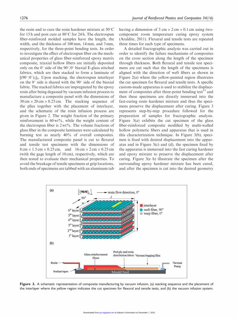
the resin and to cure the resin hardener mixture at 50�Cfor 15 h and post cure at 80�C for 24 h. The electrospunfiber-reinforced molded samples have the length, thewidth, and the thickness of 100mm, 14mm, and 3mm,respectively, for the three-point bending tests. In orderto investigate the effect of electrospun fiber on the mech-anical properties of glass fiber-reinforced epoxy matrixcomposite, triaxial hollow fibers are initially depositedonly on the 0� side of the 90�/0� biaxial E-glass stitchedfabrics, which are then stacked to form a laminate of[(90�/0�)3]S. Upon stacking, the electrospun interlayeron the 0� side is shared with the 90� side of the biaxialfabric. The stacked fabrics are impregnated by the epoxyresin after being degassed by vacuum infusion process tomanufacture a composite panel with the dimensions of30 cm� 20 cm� 0.25 cm. The stacking sequence ofthe plies together with the placement of interlayer,and the schematic of the resin infusion process aregiven in Figure 2. The weight fraction of the primaryreinforcement is 60wt%, while the weight content ofthe electrospun fiber is 2wt%. The volume fractions ofglass fiber in the composite laminates were calculated byburning test as nearly 40% of overall composites.The manufactured composite panel is cut to flexuraland tensile test specimens with the dimensions of8 cm� 1.5 cm� 0.25 cm, and 16 cm� 2 cm� 0.25 cm(with the gage length of 10 cm), respectively, which arethen tested to evaluate their mechanical properties. Toavoid the breakage of tensile specimens at grip locations,both ends of specimens are tabbed with an aluminum tab
having a dimension of 3 cm� 2 cm� 0.1 cm using two-component room temperature curing epoxy system(Araldite, 2011). Flexural and tensile tests are repeatedthree times for each type of specimens.
A detailed fractographic analysis was carried out inorder to identify the failure mechanisms of compositeson the cross section along the length of the specimenthrough thickness. Both flexural and tensile test speci-mens are cut such that the length of the specimens isaligned with the direction of weft fibers as shown inFigure 2(a) where the yellow-painted region illustratesthe cut specimen for flexural and tensile tests. A specificcustom-made apparatus is used to stabilize the displace-ment of composites after three-point bending test15 andthen these specimens are directly immersed into thefast-curing resin–hardener mixture and thus the speci-mens preserve the displacement after curing. Figure 3represents step-by-step procedure followed for thepreparation of samples for fractographic analysis.Figure 3(a) exhibits the cut specimen of the glassfiber-reinforced composite modified by multi-walledhollow polymeric fibers and apparatus that is used inthis characterization technique. In Figure 3(b), speci-men is fixed with desired displacement into the appar-atus and in Figure 3(c) and (d), the specimen fixed bythe apparatus is immersed into the fast curing hardenerand epoxy mixture to preserve the displacement aftercuring. Figure 3(e–h) illustrate the specimen after thesurrounding epoxy hardener mixture has been cured,and after the specimen is cut into the desired geometry
Figure 2. A schematic representation of composite manufacturing by vacuum infusion, (a) stacking sequence and the placement of
the interlayer where the yellow region indicates the cut specimen for flexural and tensile tests, and (b) the vacuum infusion system.
1276 Journal of Reinforced Plastics and Composites 34(16)
at Sabanci Universitesi on December 7, 2015jrp.sagepub.comDownloaded from

for the next step. The cut specimen containing failurearea of three-point bending specimen is polished andthen coated with Au/Pd for scanning electron micro-scope (SEM) characterization (Figure 3(i)).
The surface morphologies of fibers and cross-sec-tional area of specimens after breakage were analyzedby a Leo Supra 35VP field emission SEM. The mech-anical tests were conducted by using ZWICK Proline100 Universal Test Machine with 10 and 100 kN loadcells for three-point bending and tensile tests, respect-ively, using a constant cross-head speed of 2mm/min.ASTM D790-03 and ASTM D5083—02 standards areused for three-point bending and tensile tests to meas-ure mechanical properties of composite samples,respectively. Dynamic Mechanical Analyzer (DMA)(Netzsch DMA 242C) is used to analyze mechanicalproperties of the composite as a function of tempera-ture, time, and frequency.
Results and discussion
Surface morphologies of triaxial hollow fibers
Three different types of triaxial hollow electrospun fiberwere fabricated to investigate the effect of the type of
outer layer polymer, and fibers diameter on the mech-anical properties of composites, namely, PMMA/PAAm hollow fibers fabricated by using two differentouter wall solvents (i.e., DMF and EA) and PS/PAAmhollow fibers with the outer wall solvent of EA. Figure4 exhibits the fiber morphology of triaxial hollow elec-trospun fibers with outer wall of PMMA and PS andinner wall of PAAm. The effect of solvent type on fibermorphology during electrospinning process is alsoinvestigated. When DMF is used as an outer wall solv-ent in PMMA, the resulting fiber diameter is about100 nm as shown in Figure 4(a). On the other hand,higher vapor pressure of EA as outer wall solvent inPMMA leads to the formation of fibers with diameterlarger than 500 nm as can be seen in Figure 4(b).As discussed in detail in our previous paper,16 thepolymeric jet of the outer wall solution preparedby using low vapor pressure solvent is subjected tothe instabilities of electrospinning process at longertime and thus, the diameter of fibers is reduced beforereaching the surface of the collector. On the otherhand, the utilization of higher vapor pressure solventresults in faster drying of polymeric jet during electro-spinning, thereby producing fibers with a largerdiameter.
Figure 3. Step-by-step procedure followed for sample preparations for the analysis of failure mechanisms.
Zanjani et al. 1277
at Sabanci Universitesi on December 7, 2015jrp.sagepub.comDownloaded from

During the handling of the electrospun fiber mat, itwas observed that increasing the solvent pressuremakes fibers more brittle. This observation can be sub-stantiated as follows. Note that multi-walled fibers withsmaller and larger diameters produced by the same wallmaterials are expected to have the similar strain valuesat breakage. Defining the strain as "¼d/r where d is thefiber diameter and r is the radius of curvature due to thebending, one can readily infer that the fiber having alarger diameter should break with the bigger radius ofcurvature, hence giving rise to more brittle behavior,whereas fibers with smaller diameter should be capableof being bent to smaller radius of curvature, thus evok-ing more bending capabilities. Figure 4(c) representstriaxial hollow electrospun fiber with outer wall of PSand the diameter of these fibers is almost same as theone having the outer wall polymer of PMMA synthe-sized by EA solvent shown in Figure 4(b).
Flexural properties of triaxial hollow fiber-reinforcedcomposites
The effect of outer wall material of triaxial hollow fiber. Theinterfacial interactions between outer wall of electro-spun fiber and polymer matrix play a critical role totransfer the load from matrix to the reinforcing agentthus improving the mechanical properties of composite.Herein, different outer wall materials are used to tailor
the interface properties of electrospun fibers and to pro-vide the best possible interface between electrospunfibers and epoxy matrix. Figure 5 presents a compari-son of stress–strain curves of electrospun fiber-rein-forced composite specimens and neat epoxyspecimens. The flexural modulus of PS–PAAm triaxialhollow fiber-reinforced composite slightly increases,while the brittleness of the specimens increases signifi-cantly which can be noted upon comparing the strainsat fracture for PS–PAAm reinforced and neat speci-mens that are nearly 7� 0.5% and 14� 0.3%, respect-ively. Moreover, referring to flexural strengths ofPS–PAAm, triaxial hollow fiber-reinforced and neatspecimens, which are respectively 79� 0.5MPa and75� 0.4MPa, one can see that PS–PAAm triaxialhollow fibers increase the load-bearing capacity of thematrix. The PMMA–PAAm triaxial hollow fiber-rein-forced composite also shows an increase in flexuralmodulus and yield strength in comparison to specimensreinforced by PS–PAAm triaxial hollow fibers. This canbe attributed to better interfacial compatibility betweenthe PMMA wall of electrospun fibers and epoxymatrix, which can be further elaborated as follows.As depicted in Figure 6, PMMA chains in outer shellof electrospun fibers are partially dissolved therebyinterpenetrating into epoxy and hardener mixture,resulting in the entanglement of linear PMMA chainswith the cross-linked matrix network and hence the
Figure 4. SEM images of triaxial hollow electrospun fibers of (a) PMMA/PAAm fibers fabricated by outer wall solvent of DMF,
(b) PMMA/PAAm fibers fabricated by outer wall solvent of EA and (c) PS/PAAm fibers fabricated by outer wall solvent of EA.
1278 Journal of Reinforced Plastics and Composites 34(16)
at Sabanci Universitesi on December 7, 2015jrp.sagepub.comDownloaded from

formation of semi-interpenetrating polymer network(semi-IPN) structure, which lends itself to an improvedload transfer between matrix and electrospun fibers.13
The effect of fiber diameter. The diameter of electrospunreinforcing fibers is another critical parameter affectingthe mechanical properties of the composite. In Figure 7illustrates the stress–strain curves for composites rein-forced by PMMA–PAAm triaxial hollow fibers of dif-ferent diameters while keeping the electrospun fibercontent constant for both cases at 0.2wt%. PMMA–PAAm triaxial hollow fibers with an average diameterof 100 nm increase the modulus of composite specimenup to 1.72� 0.03 Gpa, which is significantly higher thanthe modulus of 1.44� 0.02GPa obtained for specimenreinforced by fibers with an average diameter of
500 nm. Moreover, electrospun fibers with an averagediameter of 100 nm increase flexural strength of speci-mens up to 91� 0.4MPa. This improvement in the flex-ural properties of composites is attributed to theincrease in specific surface area of electrospun fibersdue to the decrease in the diameter, which enhancesthe interactions between the electrospun fibers and thematrix, thereby leading to better load transfer betweenthem. On the other hand, finer electrospun fibers shiftthe failure strain to lower strain levels, which might beattributed to the increase in the number of interface inthe composites that can act as crack initiation or stressconcentration sites.
The effect of fiber content. The effect of electrospun fiberamount on the flexural properties of specimens is also
Figure 5. Flexural stress–strain curves of samples for neat epoxy and samples reinforced by 0.2 wt% PSPAAm and 0.2 wt% PMMA–
PAAm triaxial hollow fibers. Both fibers are produced with the outer layer solvent of EA and inner layer solvent of water.
Figure 6. Schematic representation of semi-IPN structure formation in PMMA–PAAm triaxial hollow fiber-reinforced composite:
(a) PMMA–PAAm triaxial hollow fiber, (b) partial dissolution of PMMA shell into the resin and hardener mixture, and (c) semi-IPN
structure formation.
Zanjani et al. 1279
at Sabanci Universitesi on December 7, 2015jrp.sagepub.comDownloaded from

investigated by comparing two different fiber contentsof 2 and 0.2wt%. Figure 8 reveals an increase in flex-ural modulus of specimens even with low fiber contentof 0.2wt%, whereas raising the fiber content to 2wt%further increases the modulus up to 1.63� 0.02GPa
from the value of 1.34� 0.01 for neat epoxy specimens.The notable rise in the modulus upon increasing thefiber content is explained by augmenting the accessibleinterfaces between reinforcing electrospun fibers insidethe specimens with epoxy matrix, thereby leading to
Figure 7. Flexural stress–strain curves of neat epoxy sample and samples reinforced by PMMA–PAAm triaxial hollow fibers with
different fiber diameters.
Figure 8. Flexural stress–strain curves of neat epoxy specimen and specimens reinforced with 0.2 wt% and 2 wt% PS–PAAm triaxial
hollow fiber.
1280 Journal of Reinforced Plastics and Composites 34(16)
at Sabanci Universitesi on December 7, 2015jrp.sagepub.comDownloaded from

further load transfer to fibers and increasing the modu-lus. It is also observed that increasing the fiber amountchanges the behavior of specimens from ductile tobrittle behavior and specimens start to get damagedat lower strain levels, which again can be attributedto the increase in the number of interfaces pos-sibly acting as crack initiation or stress concentrationpoints.
Table 2 summarizes flexural strength and flexuralmodulus of hollow fibers reinforced composites interms of percentages. The results show that hollowfibers with outer wall of PMMA and the fiber diameter
of 100 nm significantly enhance flexural strength andflexural modulus of composite.
Fracture surface analysis of hollow fiber-reinforcedcomposites
Figure 9 gives SEM images for the fracture surfaces ofneat epoxy samples and electrospun fiber-reinforcedcomposites subjected to three-point bending tests. Ingeneral, the fracture surface of the electrospun fiber-reinforced sample looks rougher and more fragmentedthan that of the neat one. Figure 9(c) exhibits the
Figure 9. SEM images of fracture surface of specimens after three-point bending tests, (a) neat epoxy, (b) PMMA/PAAm triaxial
hollow fiber-reinforced composite with the outer layer solvent of EA and (c,d) close-up view for PMMA–PAAm triaxial hollow fiber-
reinforced composite.
Table 2. Improvements in the flexural strength and modulus of hollow fibers reinforced composites in percentage.
Reinforcement
PMMA–PAAm
hollow fiber
PS–PAAm
hollow fiber
PMMA–PAAm
hollow fiber
PS–PAAm
hollow fiber
Fiber diameter (nm) 500 500 100 500
Reinforcement amount (wt%) 0.2 0.2 0.2 2
Flexural strength (MPa) 82� 0.3 79� 0.5 91� 0.4 70.5� 0.5
Flexural strength improvement (%) 9.3� 1 5.3� 1.2 21.3� 1.2 � 5.9� 1.2
Flexural modulus (GPa) 1.44� 0.02 1.38� 0.02 1.72� 0.03 1.63� 0.02
Flexural modulus improvement (%) 7.4� 2.2 2.3� 0.7 28.4� 3.2 21.6� 0.5
Note: PMMA, polymethyl methacrylate; PAAm, polyacrylamide; PS, polystyrene.
Zanjani et al. 1281
at Sabanci Universitesi on December 7, 2015jrp.sagepub.comDownloaded from

formation of semi-IPN structure around electrospunfibers, which increase the fiber diameter as well ascovers the fiber with thick layer of cross-linked epoxyresin, thus providing higher interfacial interaction andload transfer between the electrospun fibers and epoxymatrix. Figure 9(d) shows the breakage of electrospunfibers at failure area of specimen.
Laminated glass fiber-reinforced composites byhollow fibers
In Figure 10, the flexural properties obtained fromthree-point bending test shows minor enhancement inflexural modulus from 10.8� 0.2GPa for conventionalglass-fiber reinforced specimens up to 11.5� 0.2GPafor samples modified by PMMA–PAAm triaxialhollow fibers interlayers electrospun with the outerwall solvent of DMF. As can be seen from Figure 10,there are some sudden changes in stress values at higherstress and strain ranges associated with failure of indi-vidual reinforcing glass fiber plies. The first suddendrop in the stress value is considered as the breakageof first layer of glass fibers. The presence of PMMA–PAAm triaxial hollow fibers interlayers improves thebreakage strain of first layer of glass fibers by around12.5%. Furthermore, the complete failure of electro-spun modified samples is shifted to higher strain levelby nearly 20%. The flexural strength of electrospun
fiber-integrated specimen increases by 14%. Referringto results in Figure 11, one may note that there is nochange in tensile properties between neat and electro-spun interlayers integrated glass fiber-reinforced epoxycomposite specimens. The significant differencebetween the results of flexural and tensile tests mightbe attributed to the dissimilarity in the breakage mech-anisms for the flexural and the tensile tests. During theflexural test, primary glass fibers are bent perpendicularto the direction of the applied force and in turndamaged leading to formation of cracks, which propa-gate across the plies of the primary reinforcement. Theinterlayers between the plies of the primary reinforce-ment stabilize the crack propagation through arrestingcracks, thereby giving rise to toughening. However,during tensile test, the direction of applied force isthrough the plane of matrix and cracks are formedtransversely in the plane of plies and not across theplies, hence electrospun interlayers cannot act as effi-cient crack stabilizer. As well, the tensile strength of theelectrospun fibers is significantly inferior to glass fibers.Thus, the contribution of the electrospun interlayer toaxial load-bearing capacity is negligible in comparisonto primary glass fiber reinforcement. The current resultof the tensile tests can alternatively be interpreted suchthat the interlayer does not imperil the tensile proper-ties of composite structure through acting as defects atthe interface regions of the composite laminas.
Figure 10. Flexural stress–strain curves of glass fiber-reinforced epoxy specimen and specimen modified by interlayers of triaxial
hollow fibers of PMMA–PAAm.
1282 Journal of Reinforced Plastics and Composites 34(16)
at Sabanci Universitesi on December 7, 2015jrp.sagepub.comDownloaded from

Dynamic mechanical properties of glassfiber-reinforced composites
DMA analyzes the viscoelasticity of a material byapplying a sinusoidal force or displacement and mea-suring the corresponding response. The storage modu-lus, E 0, is proportional to the energy stored per cycle
(elastic behavior), while the loss modulus, E 00, is asso-ciated with the dissipated energy per cycle (viscousbehavior).17 Tan delta (�) is a damping term that isdefined as the ratio of the loss modulus to the storagemodulus, and the temperature corresponding to the tan� peak is often related to the glass transition tempera-ture (Tg). Figure 12 shows DMA results of specimens
Figure 11. Tensile stress versus strain curves of glass fiber-reinforced epoxy specimen and specimen modified by interlayers of
triaxial hollow fiber of PMMA–PAAm.
Figure 12. Tan d and E0 curves of glass fiber-reinforced specimens with and without nanofiber interlayers.
Zanjani et al. 1283
at Sabanci Universitesi on December 7, 2015jrp.sagepub.comDownloaded from

with and without nanofiber interlayers. Referring to thetan d curves of composites in this figure, Tg of compositespecimenwith nanofibers (Tg¼ 73�C) is greater than thatof neat composite (Tg¼ 66�C). This increase stems fromsemi-IPN formed through the entanglement of linearPMMA chains having a Tg of 123�C with crosslinked
epoxy matrix with lower Tg18 since semi-IPN structure
may restrict the segmental motion of the matrix leadingto higher energy requirement for the glass transition.19
The increase inTg of the composite makes it also suitablefor high temperature engineering applications. The sig-nificant increase in tan � peak of nanofiber-modified
Figure 13. SEM images of cross-sectional area of (a,b) glass fiber-reinforced epoxy specimen without nanofiber interlayers before
applying load, (c,d) glass fiber-reinforced epoxy specimen modified by nanofiber interlayers before applying load, (e,f) glass fiber-
reinforced specimen without nanofiber interlayers after bending, (g–i) glass fiber-reinforced specimen modified by nanofiber interlayers
after bending.
1284 Journal of Reinforced Plastics and Composites 34(16)
at Sabanci Universitesi on December 7, 2015jrp.sagepub.comDownloaded from

specimen might be attributed to the presence of thermo-plastic nanofiber interlayers, which experience increasingchain mobility at higher temperature. In addition, thestorage modulus of specimen with nanofiber interlayersat glassy region (before Tg) is higher than the neat speci-men since electrospun fibers provide strong interfacialadhesion between glass fibers and epoxy matrix, whichis also in agreement with the result of flexural tests atroom temperature. The storage modulus of specimenlaminated with nanofibers in rubbery region (after Tg)is lower than that of neat specimen due to the presence ofthermoplastic polymeric hollow fibers at the interfaceof matrix and glass fibers and higher viscous behaviorof these hollow fibers than thermoset matrix at elevatedtemperature.
Microscopic observation and failure mechanisms
To investigate the failure mechanisms of composites, afractographic analysis is performed on the cross sectionof flexural test specimens (bounded by length and thethickness). Figure 13 represents SEM images of cross-sectional areas of flexural test specimens after cuttingand polishing steps. The cross section corresponds tothe right-hand side view of Figure 2(a). Therefore, inthe SEM images, the most outer fibers are parallel tothe image plane. In these specimens, there are three dis-tinct regions; namely, fibers oriented in a parallelmanner to the cross section plane, fibers oriented per-pendicularly to cross section plane, and matrix-richregions. Figure 13(a) demonstrates the cross section ofneat glass fiber-reinforced specimen before applying anyforce or displacement and Figure 13(b) presents a close-up view for the boxed region in Figure 13(a). Figure13(c) and (d) exhibit the cross section of specimens lami-nated with triaxial hollow fibers before bending. SEMimages of both specimens before the application of flex-ural force confirm that fibers are satisfactorily wetted bymatrix. The failure behaviors of both neat specimen andspecimen with triaxial hollow fibers after bending areshown in Figure 13(e–i). In Figure 13(e) and (f), onlythe first outer layer (specimen surface at the supportside) of the neat specimen is broken down after bending.On the other hand, higher stress is required to breakdown the layers of specimen laminated with triaxialhollow fibers and after bending, cracks start at bothinner (Figure 13(h)) and outer layers, and the crackinitiated at outer layer (Figure 13(i)) propagatestoward inner layers (Figure 13(g)).
Conclusions
Novel architecture of triaxial electrospun hollow fiberswith controlled diameter and morphology is fabricatedby multiaxial electrospinning technique. The effect of
electrospun fibers with different wall materials, morph-ology, diameter, and fiber content on the mechanicalperformance of composite specimens is studied. Twodifferent composite production techniques which arecasting onto a Teflon mold and vacuum infusion areapplied to produce composite structures. Some of themost important findings of the current study might beconcisely summarized as;
. Electrospun fibers with PMMA outer shell enhancethe flexural modulus and strength without affectingthe toughness of samples, whereas PS outer wallenhances the flexural modulus and strength at theexpense of reducing the toughness.
. Specimens reinforced by finer electrospun fibersshow higher enhancement in flexural modulus atthe price of shifting the failure strain to lowerstrain levels.
. The increase in the amount of electrospun fibers aug-ments accessible interfaces between reinforcing electro-spun fibers and epoxy matrix in composites, therebyimproving load transfer capability and in turn the flex-ural modulus of the composites. However, the asso-ciated increase in the stress concentration pointsdue to the higher number of interfaces degrade theflexural strength as well as strain at breakage.
. The utilization of PMMA–PAAm hollow fiber asinter layers of glass fiber-laminated composites,enhances the flexural modulus by 6.5%, flexuralstrength by 14%, the onset of first layer of glassfabric failure strain by 12.5%, and final failurestrain by 20%. DMA results for glass fiber-rein-forced specimens laminated with nanofiber inter-layers show 7�C increase in Tg in comparison toneat specimens. Especially, these improvements inconventional glass fiber composites open up newway to produce more reliable and long-lasting com-posites. Consequently, hollow fiber reinforcement isa promising material for the production of advancecomposites with ultra lightweight, multifunctionalityand an improved structural performance.
The future studies will involve the integration of nano-particles into the outer layer of multi-walled hollowfibers to further enhance the performance of epoxycomposites. Also, the desired materials can be encapsu-lated inside the hollow fibers in a single step duringelectrospinning process, which will bring additionalfunctionalities into epoxy composite structures suchas vascular self-healing.
Acknowledgements
The authors thank to Cagatay Yilmaz, Ataman Deniz, andEsat Selim Kocaman for their help in the preparation of com-posite samples.
Zanjani et al. 1285
at Sabanci Universitesi on December 7, 2015jrp.sagepub.comDownloaded from

Conflict of interests
None declared.
Funding
The authors gratefully acknowledge financial support fromthe Scientific and Technical Research Council of Turkey(TUBITAK) with the project numbers of 112M312/COST
MP1202 and 112M357.
References
1. Godara A, Gorbatikh L, Kalinka G, et al. Interfacial shearstrength of a glass fiber/epoxy bonding in composites mod-
ified with carbon nanotubes. Compos Sci Technol 2010; 70:1346–1352.
2. Lubineau G and Rahaman A. A review of strategies forimproving the degradation properties of laminated contin-
uous-fiber/epoxy composites with carbon-based nanorein-forcements. Carbon 2012; 50: 2377–2395.
3. Ozden-Yenigun E, Menceloglu YZ and Papila M.
MWCNTs/P(St-co-GMA) composite nanofibers of engin-eered interface chemistry for epoxy matrix nanocompo-sites. ACS Appl Mater Interf 2012; 4: 777–784.
4. De Schoenmaker B, Van der Heijden S, De Baere I, et al.Effect of electrospun polyamide 6 nanofibres on the mech-anical properties of a glass fibre/epoxy composite. PolymTesting 2013; 32: 1495–1501.
5. Ozden E, Menceloglu YZ and Papila M. Engineeringchemistry of electrospun nanofibers and interfaces innanocomposites for superior mechanical properties. ACS
Appl Mater Interf 2010; 2: 1788–1793.6. Dzenis YA and Reneker DH. Delamination resistant com-
posites prepared by small diameter fiber reinforcement at
ply interfaces. Google Patents, 2001.7. Li G, Li P, Zhang C, et al. Inhomogeneous toughening of
carbon fiber/epoxy composite using electrospun polysul-
fone nanofibrous membranes by in situ phase separation.Compos Sci Technol 2008; 68: 987–994.
8. Sihn S, Kim RY, Huh W, et al. Improvement of damageresistance in laminated composites with electrospun nano-
interlayers. Compos Sci Technol 2008; 68: 673–683.
9. Zhang J, Lin T and Wang XG. Electrospun nanofibre
toughened carbon/epoxy composites: effects of polyether-
ketone cardo (PEK-C) nanofibre diameter and interlayer
thickness. Compos Sci Technol 2010; 70: 1660–1666.10. Bilge K, Ozden-Yenigun E, Simsek E, et al. Structural
composites hybridized with epoxy compatible polymer/
MWCNT nanofibrous interlayers. Compos Sci Technol
2012; 72: 1639–1645.11. Bilge K, Venkataraman S, Menceloglu YZ, et al. Global
and local nanofibrous interlayer toughened composites
for higher in-plane strength. Compos Part A-Appl S
2014; 58: 73–76.12. Gao Y, Sagi S, Zhang L, et al. Electrospun nano-scaled
glass fiber reinforcement of bis-GMA/TEGDMA dental
composites. J Appl Polym Sci 2008; 110: 2063–2070.13. Lin S, Cai Q, Ji J, et al. Electrospun nanofiber reinforced
and toughened composites through in situ nano-interface
formation. Compos Sci Technol 2008; 68: 3322–3329.14. Monfared Zanjani JS, Okan BS, Yildiz M, et al.
Fabrication and morphological investigation of multi-
walled electrospun polymeric nanofibers. MRS Proc
2014; 1621: 119–126.
15. Demircan O, Ashibe S, Kosui T, et al. Mechanical prop-
erties of biaxial weft-knitted and cross-ply thermoplastic
composites. J Thermoplast Compos Mater 2014:
0892705713519119.16. Seyyed Monfared Zanjani J, Saner Okan B, Letofsky-
Papst I, et al. Rational design and direct fabrication of
multi-walled hollow electrospun fibers with controllable
structure and surface properties. Eur Polym J 2015; 62:
66–76.
17. Goertzen WK and Kessler MR. Dynamic mechanical
analysis of carbon/epoxy composites for structural pipe-
line repair. Compos Part B: Eng 2007; 38: 1–9.
18. Kalogeras IM and Brostow W. Glass transition tempera-
tures in binary polymer blends. J Polym Sci Part B:
Polym Phys 2009; 47: 80–95.19. Hossain KMZ, Ahmed I, Parsons AJ, et al. Physico-che-
mical and mechanical properties of nanocomposites pre-
pared using cellulose nanowhiskers and poly(lactic acid).
J Mater Sci 2012; 47: 2675–2686.
1286 Journal of Reinforced Plastics and Composites 34(16)
at Sabanci Universitesi on December 7, 2015jrp.sagepub.comDownloaded from