Journal of Engineering An Effective Finite Element Method...
13
International Journal of Engineering and Technology Volume 3 No. 4, April, 2013 ISSN: 2049-3444 © 2013 – IJET Publications UK. All rights reserved. 407 An Effective Finite Element Method for Beam Based Compliant Mechanism Theddeus T. Akano, Omotayo A. Fakinlede Department of Systems Engineering, University of Lagos, Akoka, Lagos. ABSTRACT This paper presents a nonlinear analysis of compliant mechanisms (CMs i ) using finite element method. The case of a compliant four-bar mechanism, where the coupler link is to be guided by flexible input and follower links is developed. Previous works on this type of compliant mechanism are based on linear formulation thereby neglecting the shear stress induced in the links. An investigation on the influence of geometric nonlinearity in the analysis of compliant mechanisms where all flexible links are considered as two dimensional beams with shear deformation is presented. The energy equations were developed first; the discretization and the lagrangian dynamics that produced the motion equation were thereafter established. The automatic derivation of formulae needed in numerical procedure were done using symbolic programming module, AceGEN and implemented in a compiled back end, AceFEM. Finally, the numerical results reveal the deviation that exists with linear formulation assumption, showing that this approach is more encompassing. Keywords: Compliant Mechanisms, Symbolic Programming, Finite Element Method, AceGEN, AceFEM, Geometric Nonlinearity (GNL ii ) 1. INTRODUCTION A mechanism is a mechanical device which transfers forces and motions from an input source to output link [1]. A compliant mechanism (CM) is a mechanism that gains some or all of its motion from the deformation of slender segments rather than from relative motion between rigid-body links connected by joints [2]. The popularity of compliant mechanisms is expected to grow since the compliance grants the designer greater freedom in the number of possible solutions for a given problem. However, this freedom in design is often offset by difficulties encountered in the analysis of the compliant members. The use of compliance presents several advantages including part count reduction, absence of coulomb friction, no need for lubrication, more precise motion, compactness, etc. Recently, there are several examples of compliant mechanisms that have been designed and widely used in various fields such as for adaptive structures, biomedical, hand-held tools, components in transportations, Microelectromechanical Systems (MEMS iii ) and robotics. However, the design of CMs is complicated by the flexible members which include elastic links and elastic hinges. These usually undergo large deflections which introduce geometric nonlinearities. Therefore, the study of large deflections in elastic beams has long been one of the central themes of interest aiming at accurately describing the deformation in CMs [2, 3]. Since in these applications, curvature is nonlinear due to geometrical nonlinearities, a nonlinear mathematical formulation should be considered. Consequently, deflections are difficult to determine by analytical methods, hence numerical method should be employed. Due to the complexity of the nonlinear governing equations, only a few studies have been carried out so far to investigate the nonlinear deformation of CMs [4-8]. A number of researchers have worked on the analysis of compliant mechanism using the Pseudo Rigid Body Model (PRBM iv ) [9-16]. Some have also employed the application of finite element method on the analysis of compliant mechanisms [17-20]. Many other researchers have adopted many ways to synthesize the mechanism [21-32]. However, these analyses are based on linear assumptions. It is obvious that these cannot give a true understanding of the performance of compliant mechanisms. At present, there are few studies on the synthesis of compliant mechanisms by topology optimization based on large displacement of the mechanisms using geometrically nonlinear finite element models [33-36]. Geometric nonlinearity in the formulation of flexible multibody system dynamics may arise from an orientation change in the body through a number of rotations and from the occurrence of large displacements induced by elastic deformation. The former must always be considered in the analysis, even in dealing with systems consisting of bodies that are analysed under the rigid body hypothesis. However, the latter are only significant in those cases where strong deflections of the elements and/or major axial forces in the deformed configurations are considerably different from those for the undeformed configurations. Previous works on this type of compliant mechanism neglected the shear stress induced in the links. The
-
Upload
phunghuong -
Category
Documents
-
view
218 -
download
1
Transcript of Journal of Engineering An Effective Finite Element Method...

International Journal of Engineering and Technology Volume 3 No. 4, April, 2013
ISSN: 2049-3444 © 2013 – IJET Publications UK. All rights reserved. 407
An Effective Finite Element Method for Beam Based Compliant
Mechanism
Theddeus T. Akano, Omotayo A. Fakinlede
Department of Systems Engineering, University of Lagos, Akoka, Lagos.
ABSTRACT
This paper presents a nonlinear analysis of compliant mechanisms (CMsi) using finite element method. The case of a
compliant four-bar mechanism, where the coupler link is to be guided by flexible input and follower links is developed.
Previous works on this type of compliant mechanism are based on linear formulation thereby neglecting the shear stress
induced in the links. An investigation on the influence of geometric nonlinearity in the analysis of compliant mechanisms
where all flexible links are considered as two dimensional beams with shear deformation is presented. The energy equations
were developed first; the discretization and the lagrangian dynamics that produced the motion equation were thereafter
established. The automatic derivation of formulae needed in numerical procedure were done using symbolic programming
module, AceGEN and implemented in a compiled back end, AceFEM. Finally, the numerical results reveal the deviation that
exists with linear formulation assumption, showing that this approach is more encompassing.
Keywords: Compliant Mechanisms, Symbolic Programming, Finite Element Method, AceGEN, AceFEM, Geometric Nonlinearity (GNLii)
1. INTRODUCTION
A mechanism is a mechanical device which transfers
forces and motions from an input source to output link
[1]. A compliant mechanism (CM) is a mechanism that
gains some or all of its motion from the deformation of
slender segments rather than from relative motion
between rigid-body links connected by joints [2]. The
popularity of compliant mechanisms is expected to grow
since the compliance grants the designer greater freedom
in the number of possible solutions for a given problem.
However, this freedom in design is often offset by
difficulties encountered in the analysis of the compliant
members. The use of compliance presents several
advantages including part count reduction, absence of
coulomb friction, no need for lubrication, more precise
motion, compactness, etc. Recently, there are several
examples of compliant mechanisms that have been
designed and widely used in various fields such as for
adaptive structures, biomedical, hand-held tools,
components in transportations, Microelectromechanical
Systems (MEMSiii) and robotics. However, the design of
CMs is complicated by the flexible members which
include elastic links and elastic hinges. These usually
undergo large deflections which introduce geometric
nonlinearities. Therefore, the study of large deflections in
elastic beams has long been one of the central themes of
interest aiming at accurately describing the deformation in
CMs [2, 3]. Since in these applications, curvature is
nonlinear due to geometrical nonlinearities, a nonlinear
mathematical formulation should be considered.
Consequently, deflections are difficult to determine by
analytical methods, hence numerical method should be
employed. Due to the complexity of the nonlinear
governing equations, only a few studies have been carried
out so far to investigate the nonlinear deformation of CMs
[4-8].
A number of researchers have worked on the analysis of
compliant mechanism using the Pseudo Rigid Body
Model (PRBMiv) [9-16]. Some have also employed the
application of finite element method on the analysis of
compliant mechanisms [17-20]. Many other researchers
have adopted many ways to synthesize the mechanism
[21-32]. However, these analyses are based on linear
assumptions. It is obvious that these cannot give a true
understanding of the performance of compliant
mechanisms. At present, there are few studies on the
synthesis of compliant mechanisms by topology
optimization based on large displacement of the
mechanisms using geometrically nonlinear finite element
models [33-36]. Geometric nonlinearity in the formulation
of flexible multibody system dynamics may arise from an
orientation change in the body through a number of
rotations and from the occurrence of large displacements
induced by elastic deformation. The former must always
be considered in the analysis, even in dealing with
systems consisting of bodies that are analysed under the
rigid body hypothesis. However, the latter are only
significant in those cases where strong deflections of the
elements and/or major axial forces in the deformed
configurations are considerably different from those for
the undeformed configurations.
Previous works on this type of compliant mechanism
neglected the shear stress induced in the links. The

International Journal of Engineering and Technology (IJET) – Volume 3 No. 4, April, 2013
ISSN: 2049-3444 © 2013 – IJET Publications UK. All rights reserved. 408
pseudo-rigid body model neglects the shear stress and/or
force that could be induced in the compliant links as they
deflect, in order for a compliant mechanism to undergo
any amount of motion. The pseudo rigid body model is
replaced by a two-dimensional nonlinear finite element
formulation for the beam with shear deformation.
We shall focus our work on a four-bar mechanism (See
Fig. 1.), which is a closed-loop kinematic chain. One of
the links is called the coupler link, and is the only one that
can trace paths of arbitrary shape because it is not rotating
about a fixed pivot. Apart from [37] which focused on the
synthesis of the input and follower links simultaneously
through optimisation of the finite element model, previous
research on this type of mechanism comprised of at least
one moving rigid link, and the coupler link was always
considered a rigid member, because the motion generation
objective is based on the task definition for conventional
rigid-link mechanisms.
Fig. 1. A four-bar mechanism
In this paper, a compliant four-bar mechanism is
considered, because all its motion is obtained from the
deflection of compliant members. The bars are modeled
as beams with shear deformation, thus involving the
guidance of a flexible link rather than a rigid body.
This work uses a system of symbolic and algebraic
programming (Mathematica) and within it a developed
modules AceGen, AceFEM and AceShare [38] which
together constitute a system named Symbolic Mechanics
System [39]. Mathematica is a basic and very powerful
tool for working with formulae and to perform various
mathematical operations and expressions on computers.
Modern versions include the possibility of presenting
results and numerical analysis. AceGen is used for the
automatic derivation of formulae needed in numerical
procedures. The AceGen package also provides a
collection of prearranged modules for the automatic
creation of the interface between the automatically
generated code and the numerical environment where the
code would be executed. The AceGen package directly
supports several numerical environments such as
Mathlink, AceFEM, FEAP, FORTRAN, ELFEN and
ABAQUS. AceFEM is a research finite element
environment based on Mathematica, designed to solve
multi-physics and multi-field problems. The AceFEM
package explores the advantages of symbolic capabilities
of Mathematica while maintaining numerical efficiency of
commercial finite element environments.
The rest of the paper is organised as follows. Firstly, the
energy equations were developed. Secondly, the motion
equation was obtained. Finally, a numerical example of a
compliant four-bar mechanism is given for the
implementation of the model. The comparative analysis of
the effect of geometric nonlinearity on the analysis of
compliant mechanism is presented. Finally, a summary of
the highlights of the work is given the conclusion section.
2. MATHEMATICAL MODEL
The model is based on the selection of the geometry,
material properties, the loading and boundary conditions,
and any other specific assumptions made. The purpose of
the analysis is to answer certain questions regarding the
stiffness, stresses developed and strength of the structure.
Hence, when studying the behaviour of the structure, we
would like to predict the future not only when the
structure is operating in normal conditions, which mostly
only requires a linear analysis, but also when the structure
is subjected to severe loading conditions, which usually
requires a highly nonlinear analysis.
Fig. 2. Deformed and underformed beam element
Fig. 3. Detail of the beam element with shear deformation
Figure 2 shows the deformed and underformed beam
element in the x-z plane while Fig. 3. shows the detail of

International Journal of Engineering and Technology (IJET) – Volume 3 No. 4, April, 2013
ISSN: 2049-3444 © 2013 – IJET Publications UK. All rights reserved. 409
the beam element with shear deformation. R is the radius
of curvature of the beam. dx , dw and ds form a right
angled triangle. ds is a very small portion on the
centroid of the deformed beam element. L is the length
of the beam element. The curvature k of the beam
element is given as:
2
2
d wk C
dx (1)
Where
3
2
1C
dw1dx
(2)
Compliant members undergo large deflections which
introduce geometric nonlinearity. For small deflection, the
slope of the deflected middle surface are small compared
to unity so that the curvature is approximated as:
2
2
d wk
dx (3)
The deviation of the value of C from unity represents the
factor by which the compliant system undergoes large
deflection.
2.1 Kinetic Energy
In Fig. 2. the displacement vector along the neutral axis in
axial direction is given as
In Fig. 2. the displacement vector along the neutral axis in
axial direction is given as
xS aCos bSin x u (4a)
zS bCos aSin w (4b)
Eqs. (3) and (4) could be combined in the form
S aCos bSin x u i bCos aSin w k (5)
Where a and b are the coordinates of end 1 of the beam
element. x is the coordinate measured along the
element’s neutral axis from 1 to 2. is the angle between
the body motion and the x -axis. u and w are the axial
and transverse displacements of point P from the rigid
body position. For small value of , 1Cos and
Sin . Substituting these values into Eq. (5), gives
S a b x u i b a w k
(6)
Differentiating Eq. (6), the velocity of a particle at point,
P is given as:
ds d dx du d dwV b i a k
dt dt dt dt dt dt
(7)
The kinetic energy pT of beam particles can be expressed
as:
2p x
1T A V dxdz
2 (8)
Where is the mass density of the beam material and
xA is the cross sectional area of the beam element. The
kinetic energy sT associated with transverse shear is also
given as:
2
s z1 d
T I dxdz2 dt
(9)
is the measure of transverse shear angle. The angular
velocity aV of any differential line segment on the neutral
axis of the element is given by
2
ad d w
Vdt dxdt
(10)
The kinetic energy RT due to rotatory inertia of the beam
element is given as
22
R z1 d d w
T I dxdz2 dt dxdt
(11)
The total kinetic energy T of the beam element becomes
p s RT T T T (12)
It should be noted that the limits of the double integration
in Eqs. (8), (9) and (11) are from 2h to 2h and 0
to L . Eq. (12) becomes
2h 2 2 2 2L2
xz zh 0
2
1 d dx du d dw d d d wT A b a I dxdz
2 dt dt dt dt dt dt dt dxdt
(13)

International Journal of Engineering and Technology (IJET) – Volume 3 No. 4, April, 2013
ISSN: 2049-3444 © 2013 – IJET Publications UK. All rights reserved. 410
2.2 Strain – Displacement Relation
The Green strain xu , yu and zu are displacements of
the member at any point in the x , y and z directions
respectively. u , v and w are displacements of the
middle surface in the x , y and z directions
respectively. The Green strain is given as
22 2yx x z
xx
uu u u1
x 2 x x x
(14)
The von Karman strains are related to the displacement by
0 1
xx xx xxz (15)
2 2
0 x xzxx
u uu1 1 w
x 2 x x 2 x
(16)
2
1xx 2
w
x
(17)
Eq. (16) stands for the strain equation for geometric
nonlinearity due to stretching of the neutral axis. Eq. (17)
is equivalent to the curvature displacement relation for
small deflection in Eq. (3). Therefore, for large deflection
analysis which results in geometric nonlinearity due to
curvature, Eq. (15) becomes
zk0
xxxx (18)
2
22
xxx
x
wzC
x
w
2
1
x
u
(19)
In order to present realistic proportional links, the links
are assumed to be of the same cross section. Each link is
divided into elements of the same length with constant
areas. The integrations involved in the element equations
are carried out in a piecewise fashion with areas in each
section taken as a constant.
2.3 Strain Energy
The virtual strain energy for the element may be
written as
dxdz2
1dxdz xzxz (20)
Where is the normal stress, is the normal strain,
xz and xz are the shear stress and shear strain
respectively.
But,
xzxzxz G ;
2
xzx
w
(21)
Where xzG is the shear modulus. Substituting Eq. (21)
into Eq. (20), we have
dxdz
x
wG
2
1dxdz
2
xz
(22)
Differentiating Eq. (19), we have
2
2
xxx
wzC
dxx
wdw
dx
ud
(23)
Substituting Eq. (23) into Eq. (22) gives
22
xx xz2
d u w d w w 1 wzC dxdz G dxdz
dx x dx 2 xx
(24)
But,
sxzxzxzxz AqGAGdxdzG (25)
Here, q is a constant (for a rectangular section, 56q
; for a circular section, 3237q ), xzA is the x-z
plane area, sA is the shear area and sxz AG is the shear
stiffness.
22
xx xz s2
d u w d w w 1 wzC dxdz qG A dxdz
dx x dx 2 xx
(26)
International Journal of Engineering and Technology (IJET) – Volume 3 No. 4, April, 2013
ISSN: 2049-3444 © 2013 – IJET Publications UK. All rights reserved. 411
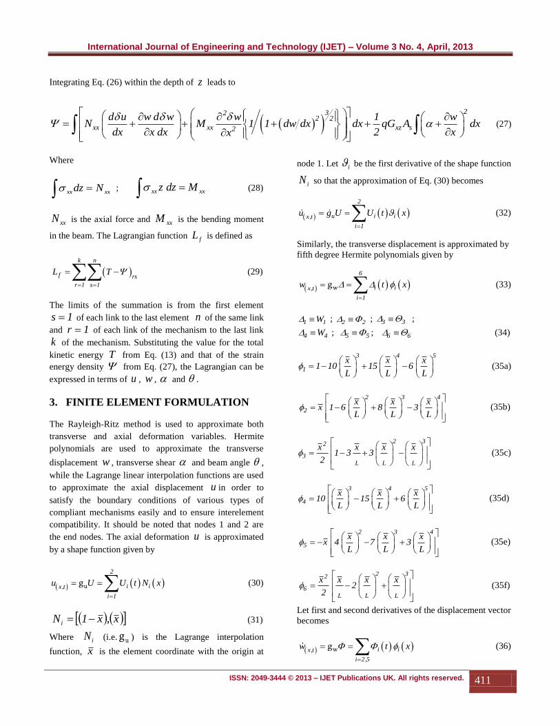
Integrating Eq. (26) within the depth of z leads to
232
2 2
xx xx xz s2
d u w d w w 1 wN M 1 1 dw dx dx qG A dx
dx x dx 2 xx
(27)
Where
xxxx Ndz ; xxxx Mdzz (28)
xxN is the axial force and xxM is the bending moment
in the beam. The Lagrangian function fL is defined as
k n
f rs
r 1 s 1
L T
(29)
The limits of the summation is from the first element
1s of each link to the last element n of the same link
and 1r of each link of the mechanism to the last link
k of the mechanism. Substituting the value for the total
kinetic energy T from Eq. (13) and that of the strain
energy density from Eq. (27), the Lagrangian can be
expressed in terms of u , w , and .
3. FINITE ELEMENT FORMULATION
The Rayleigh-Ritz method is used to approximate both
transverse and axial deformation variables. Hermite
polynomials are used to approximate the transverse
displacement w , transverse shear and beam angle ,
while the Lagrange linear interpolation functions are used
to approximate the axial displacement u in order to
satisfy the boundary conditions of various types of
compliant mechanisms easily and to ensure interelement
compatibility. It should be noted that nodes 1 and 2 are
the end nodes. The axial deformation u is approximated
by a shape function given by
2
i ix,t
i 1
u U U t N x
ug (30)
x,x1N i (31)
Where iN (i.e. ug ) is the Lagrange interpolation
function, x is the element coordinate with the origin at
node 1. Let i be the first derivative of the shape function
iN so that the approximation of Eq. (30) becomes
2
u i ix,t
i 1
u g U U t x
(32)
Similarly, the transverse displacement is approximated by
fifth degree Hermite polynomials given by
6
i ix,t
i 1
w t x
wg (33)
1 1W ; 2 2 ; 3 3 ;
4 4W ; 5 5 ; 6 6 (34)
3 4 5
1
x x x1 10 15 6
L L L
(35a)
2 3 4
2
x x xx 1 6 8 3
L L L
(35b)
2 32
3L L L
x x x x1 3 3
2
(35c)
3 4 5
4
x x x10 15 6
L L L
(35d)
2 3 4
5
x x xx 4 7 3
L L L
(35e)
2 32
6L L L
x x x x2
2
(35f)
Let first and second derivatives of the displacement vector
becomes
i ix,t
i 2,5
w t x
wg (36)

International Journal of Engineering and Technology (IJET) – Volume 3 No. 4, April, 2013
ISSN: 2049-3444 © 2013 – IJET Publications UK. All rights reserved. 412
i ix,t
i 3,6
w t x
wg (37)
For the purpose of compatibility, and are also
approximated by cubic polynomial
i ix,t
i 2,5
t x
wg (38a)
i ix,t
i 2,5
t x
wg (38b)
i ix,t
i 1,4
t x
wg (39a)
i ix,t
i 2,5
t x
wg (39b)
Substituting the approximations from Eqs. (30-39) into
Eq. (13), the kinetic energy can now be rewritten as
2 22
i i i i i i i i
i 2,5 i 1 i 2,5 i 2,5
L2
2 i i0
i 2,5
z i i
i 2,5 i i
i 2,5
b t x x U t x a t x t x
1T dxdz
t x2
I t x
t x
h
2
h
2 (40)
Equally, the strain energy density can be rewritten as
2
3j j 2 2
i j
2xx xx j j j j
j 3,6 j 2,5
j j
j 2,5
j j
j 1,4
xz s
j j
j 2,5
U t x
N M t x 1 1 t x
t x
t x
1qG A
2 t x
L
02
dx
(41)
xuxj and xwxj . The
transformation of coordinates is now introduced to change
from moving coordinates system associated with the
element to global coordinates. Only the nodal
displacements iU and iW need to be transformed. The
other coordinates are angles or derivative of angles which
are not directional on the xz coordinate system used. The
corresponding transformation is given as
1 1
1 1
1 1
2 2
2 2
2 2
U Cos Sin 0 0 0 0 U
Sin Cos 0 0 0 0
0 0 Cos Sin 0 0
U 0 0 Sin Cos 0 0 U
0 0 0 0 Cos Sin
0 0 0 0 Sin Cos
(42a)
TT
1 1 1 2 2 2 F 1 1 1 2 2 2U , , U , T U , , U , (42b)

International Journal of Engineering and Technology (IJET) – Volume 3 No. 4, April, 2013
ISSN: 2049-3444 © 2013 – IJET Publications UK. All rights reserved. 413
FT is the transformation matrix.
222111 ,U,,U are the nodal
displacements in global coordinate. Substituting the
expression from Eq. (42) into the Lagrangian equation
(Eq. (29)), the equation for the global displacement
vectors for the system is given as
2 22
i i i i i i i i
L i 2,5 i 1 i 2,5 i 2,5
2 20
z i i i i i i
i 2,5 i 2,5 i 2,5
2
xx j j j jf
i j j 2
b t x x U t x a t x t x
dxdz
I t x t x t x
1N U t x t xL
2
2h
2
h
,52
3 22L
xx j j j jj 2,50
j 3,6
2
xz s j j j j
j 1,4 j 2,5
M t x 1 t x dx
1qG A t x t x
2
k n
r 1 s 1
rs
(43)
The global coordinates for the system are given by
1 1 1 1 1 1 2 2 2 2 2 2q U , , , , , , U , , , , , (44)
Differentiating the Lagrangian with respect to the element
coordinates gives the Lagrange equation of motion.
f fL Ld0
dt q q
(45)
The operation carried out in Eq. (45) results in a system of
nonlinear element differential equations. Assembling the
element matrices for particular compliant mechanism
being solved results in the global system of equations
given as
,tt ,tM Q C Q K Q F (46)
Where
l nlK K K (47)
Q
and F are the displacement and force vectors
respectively. The M , C , lK and nlK matrices are all
functions of time t . The C matrix results from the kinetic
energy of the system. The matrix lK is the linear portion
of the stiffness matrix. The matrix nlK is the nonlinear
portion of the stiffness matrix. Eq. (46) give a system of
nonlinear equations that will be solved iteratively for a
given compliant mechanism problem. The Newton -
Raphson iteration method will be employed for the
iteration process.
4. NUMERICAL IMPLEMENTATION
A planar compliant four bar mechanism is analyzed and
presented as shown in Fig. 4. The mechanism is
constructed of polypropylene and the parameters of the
mechanism are shown in Table 1. For the finite element
approximation of the above formulations we used the
beam elements. The entire mechanism geometry was built
as adequate. The essential boundary condition was stated
with the base of the mechanism clamped. Also the natural
boundary condition at the tip of the mechanism is 280mN.
Table 1. Parameters for Simulation of Results

International Journal of Engineering and Technology (IJET) – Volume 3 No. 4, April, 2013
ISSN: 2049-3444 © 2013 – IJET Publications UK. All rights reserved. 414
Definition
Symbol
Value
Lengths of the
mechanism links
l1 = l3
l2
0.7m
0.4m
Young’s Modulus E1 = E2 = E3 1103.61MPa
Density of material ρ1 = ρ2 = ρ3 913Kg/m3
Poisson ratio v1 = v2 = v3 0.35
Breadth of the
compliant links
b1 = b3
b2
0.00318m
0.00239m
Heights of the
compliant links
h1 = h3
h2
0.00863m
0.00863m
Areas of the compliant
links
A1 = A3
A2
27.4434µm2
20.6257µm2
Second moments of
areas of the compliant
links
I1 = I3
I2
0.170325nm4
0.128012nm
4
Fig. 4. Deformed and undeformed mechanism
AceGen is used for the automatic derivation of formulae
needed in the numerical procedures. Symbolic derivation
of the characteristic quantities (e.g. gradients, tangent
operators, sensitivity vectors,…) leads to exponential
behavior of derived expressions, both in time and space.
Fig. 5. System for generating a finite element code and its
further analysis
AceGen offers multi-language code generation (Fortran,
C, Mathematica, …) and automatic interface to general
numerical environments (MathLink connection to
Mathematica) and specialized finite element environments
(AceFEM, FEAP, ELFEN, ABAQUS, …). Fig. 5. shows
the system for generating a finite element code and its
further analysis through the end compiler AceFEM.
Fig. 6. Bending Moment of the deformed mechanism
AceFEM
0.100e3Min.0.7218e2Max.
M
0.60e20.42e20.24e20.64e1
0.115e20.296e20.476e2
0.1 0.2 0.3 0.4 0.5 0.6 0.7X
0.4
0.3
0.2
0.1
0.1
0.2
Y

International Journal of Engineering and Technology (IJET) – Volume 3 No. 4, April, 2013
ISSN: 2049-3444 © 2013 – IJET Publications UK. All rights reserved. 415
Fig. 7. Axial Force of the deformed mechanism Fig. 8. Shear Force of the deformed mechanism
Fig. 9. Load – axial displacement u of the coupler midpoint Fig. 10. Load – vertical displacement v of the coupler midpoint
AceFEM
0.358e3Min.0.5025e3Max.
N
0.23e30.12e30.21e2
0.827e20.187e30.292e30.396e3
0.1 0.2 0.3 0.4 0.5 0.6X
0.5
0.4
0.3
0.2
0.1
0.1
0.2
Y
AceFEM
0.396e3Min.0.3665e3Max.
Q
0.23e30.15e30.64e2
0.219e20.108e30.194e30.280e3
0.1 0.2 0.3 0.4 0.5 0.6 0.7X
0.4
0.3
0.2
0.1
0.1
0.2
Y
0 100 200 300 400 500
0.00
0.01
0.02
0.03
0.04
0.05
0.06
Load mN
um
Linear
Shear Deformation
No Shear Deformation
0 100 200 300 400 500
0.00
0.05
0.10
0.15
0.20
0.25
Load mN
um
Linear
Shear Deformation
No Shear Deformation

International Journal of Engineering and Technology (IJET) – Volume 3 No. 4, April, 2013
ISSN: 2049-3444 © 2013 – IJET Publications UK. All rights reserved. 416
Fig. 11. Horizontal elastic motion response of the coupler midpoint
Fig. 12. Vertical elastic motion response of the coupler midpoint
0 5 10 15 20
0.003
0.002
0.001
0.000
0.001
0.002
0.003
Time ms
Hori
zon
tal
Ela
stic
Moti
on
Res
pon
sem
m
Linear
GNL
0 5 10 15 20
1.5
1.0
0.5
0.0
0.5
1.0
1.5
Time ms
Ver
tica
lE
last
icM
oti
on
Res
pon
sem
m
Linear
GNL

International Journal of Engineering and Technology (IJET) – Volume 3 No. 4, April, 2013
ISSN: 2049-3444 © 2013 – IJET Publications UK. All rights reserved. 417
5. DISCUSSION OF RESULTS
Numerical results generated for a compliant four
mechanism are reported in Figs. 6. to 13. Figures 6 to 8
are the various static deformation representations of the
complete mechanism. Figures 9 and 10 show the various
static behavior of the coupler midpoint; in this case, the
load-displacement graphs. The simulated results show a
deviation from straight line graph from linear assumptions
to normal curves considering the effect of geometric
nonlinearity. However, there is also a deviation between
the geometric nonlinear consideration when the effect of
shear stress is captured and when it is not. Initially, the
two nonlinear effects show the same behaviour until a
point where the effect of the shear stress is much that the
deviation starts becoming noticeable. The response shows
an initial steady state response and later a slight increasing
harmonic response. Figs. 11. and 12. are dynamic elastic
response of the mechanism. Unsteady conditions are
observed between 0 and 3 seconds in both cases with their
produced harmonics almost overlapping between 3 and 19
seconds, after which the responses tend to separate
noticeably for GNL and Linear signals. Initially, the
displacement amplitude changes with each motion,
stabilizes at the middle of the motion and varies towards
the end of the motion cycle.
6. CONCLUSION
Figures 9 and 10 have shown that the deviation in the
geometric nonlinear from the linear compliant systems
analysis is great. So it is shown that the influence of the
nonlinear terms in the normal strain cannot be neglected
under large deflection.
It has also been established that neglecting the effect of
shear stress may lead to incorrect result. The deviation
between the two geometric nonlinear analyses shows a
wide difference after half of the maximum input force.
Therefore, the effect of shear stress must be considered
when looking at the geometric nonlinear behaviour of
compliant mechanisms.
In Figs. 12. and 13, linear analyses have shown to be
relatively accurate in the midrange. Geometric
nonlinearity effects become critically important at the end
points. Failure may result from these end points despite
current analysis in the midrange. This further show why
compliant systems that are subjected to large deflection
may still be nonlinear even with materially linear
components.
REFERENCES
[1] A. G. Erdman, G. N. Sandor, Mechanisms Design:
Analysis and Synthesis, Prentice Hall, Englewood
Cliffs, New Delhi, 1991.
[2] L. L. Howell, Compliant Mechanisms, Wiley, New
York, 2001.
[3] J. L. Herder, F.P.A. van den Berg, Statically balanced
compliant mechanisms (SBCM's); an example and
prospects, Proceedings ASME DETC 26th Biennial,
Mechanisms and Robotics Conference, Baltimore,
Maryland, paper number DETC2000/MECH-14144,
2000.
[4] T. Bele’ndez, M. Pe’ro-Polo, C. Neipp, A .
Bele’ndez, Numerical and experimental analysis of
large deflections of cantilever beams under a
combined load, Physica scripta, 118 (2005) 61-65.
[5] K. Lee, Large defections of cantilever beams of non-
linear elastic material under a combined loading,
International Journal of Non-Linear Mechanics, 37,
(2002) 439–443.
[6] J. Wang, J. K. Chen, S. Liao, An explicit solution of
the large deformation of a cantilever beam under
point load at the free tip, Journal of Computational
and Applied Mathematics, 212 (2008) 320 – 330.
[7] P. B. Goncalves, D.L.B.R. Jurjio, C. Magluta, N.
Roitmann, Earge deflection behavior and stability of
slender bars under self weight, Structural Engineering
and Mechanics, 24 (2006) 709-725.
[8] A.M.G. Dos Anjos, P. B. Goncalves, Large deflection
geometrically non linear analysis of arches and
beams. in: coupled instabilities in metal structures,
London, Proceedings of the Coupled Instabilities in
Metal Structures. London, Imperial College Press,
(1996) 69-76.
[9] I. C. Ugwuoke, M. S. Abolarin, O. V. Ogwuagwu,
Frequency characteristics of the compliant constant-
force mechanism based on the pseudo-rigid-body
model, Assumption University Journal of Technology
(AU J.T.), 12 (3) (2009) 193-198.
[10] Y. Yu, L. L. Howell, Y. Yue, Dynamic modeling of
compliant mechanism based on the pseudo rigid body
model, journal of mech. design, 127 (2005) 760-765.
[11] S. M. Lyon, M. S. Evans, P. A. Erickson, L. L.
Howell, Dynamic response of compliant mechanisms
using the pseudo-rigid-body model, Proceedings of
ASME Design Engineering Technical Conferences,
DETC97/VIB-4177, 1997.

International Journal of Engineering and Technology (IJET) – Volume 3 No. 4, April, 2013
ISSN: 2049-3444 © 2013 – IJET Publications UK. All rights reserved. 418
[12] S. M. Lyon, P. A. Erickson, L. L. Howell,
Prediction of the first modal frequency of compliant
mechanisms using the pseudo-rigid-body model,
Journal of Mechanical Design Transactions of the
ASME, 121 (2) (1999) 309-313.
[13] C. Boyle, L. L. Howell, S. P. Magleby, Dynamic
modeling of compliant constant-force compression
mechanisms, Mech. Mach. Theory, 38 (2003) 1469-
1487.
[14] L. Saggere, S. Kota, Synthesis of Planar, Compliant
four-bar mechanisms for compliant-segment motion
generation, J. Mech. Des., 123 (4) (2001) 535-542.
[15] M. Rezaei, M. Tayefeh, M. Bahrami, Dynamic
behavior analysis of compliant micromechanisms,
Journal of Physics: Conference Series, 34 (2006)
583–588.
[16] P. Xu, Y. Jingjun, Z. Guanghua, B. Shusheng, An
effective pseudo-rigid-body method for beam-based
compliant mechanisms, Precision Engineering, 34
(2010) 634–639.
[17] Z. Li, and S. Kota, Dynamic analysis of compliant
mechanisms, Proceedings of the ASME Design
Engineering Technical Conference, 5 (2002) 43-50.
[18] W. Wang, and Y. YU, Dynamic anlysis of compliant
mechanism using finite element method, Proceedings
of IEEE/ASME International Conference on
advanced Intelligent Mechatronics, (2008) 247-251.
[19] W. Wang, Y. Yu, Dynamic analysis of compliant
mechanisms based on finite element method, Journal
of Mechanical Engineering, DOI:10.3901/JME.2010.09.079, 46 (9) 2010.
[20] X. Zhang, W. Hou, Dynamic analysis of the
precision compliant mechanisms considering thermal
Effect, Precision Engineering, 34 (2010) 592–606.
[21] R. Ansola, E. Veguerıa, A. Maturana, J. Canales, 3D
compliant mechanisms synthesis by a finite element
addition procedure, Finite Elements in Analysis and
Design, 46 (2010) 760–769.
[22] B. R. Cannon, T. D. Lillian, S. P. Magleby, L. L.
Howell, M. R. Linford, A compliant end-effector for
microscribing, Precision Engineering, 29 (2005) 86–
94.
[23] M. B. Parkinson, L. L. Howell, J. J. Cox, A
parametric approach to the optimization-based design
of compliant mechanism, ASME Design Engineering
Technical Conference, DETC97/DAC-3763,1997.
[24] N. Tolou, J. L Herder, A semi-analytical approach
to large deflections in compliant beams under point
load, Delft University of Technology, Faculty of
Mechanical, Maritime and Materials Engineering,
Department of Biomechanical Engineering,
Mekelweg 2, 2628 CD Delft, The Netherlands.
[25] A. Rubén, V. Estrella, C. Javier, J. A. Tárrago, A
simple evolutionary topology optimization procedure
for compliant mechanism design, Finite Elements in
Analysis and Design, 44 (2007) 53 – 62.
[26] B. Zettl, W. Szyszkowski, W. J. Zhang, Accurate low
DOF modeling of a planar compliant mechanism
with flexure hinges: the equivalent beam
methodology, Precision Engineering, 29 (2005) 237–
245.
[27] J. K. Charles, K. Kota, Y. Moon, An instant center
approach to the conceptual design of compliant
mechanisms, International Design Engineering
Technical Conference, DETC2004-57388, 2004.
[28] C. J. Shih, C. F. Lin, H. Y. Chen, An integrated
design of flexure hinges and topology optimization
for monolithic compliant mechanism, Society for
Design and Process Science, United States of
America, 2006.
[29] Z. Nia, D. Zhanga, Y. Wub, Y. Tiana, M. Huc,
Analysis of parasitic motion in parallelogram
compliant mechanism, Precision Engineering, 34
(2010) 133–138.
[30] N. Lobontiu, E. Garcia, Analytical model of
displacement amplification and stiffness optimization
for a class of flexure-based compliant mechanisms,
Computers and Structures, 81 (2003) 2797–2810.
[31] J. W. Liang, F. F. Brian, Balancing energy to
estimate damping in a forced oscillator with
compliant contact, Journal of Sound and Vibration,
330 (2011) 2049–2061.
[32] L. Chao-Chieh, Computational Models for Design
and Analysis of Compliant Mechanisms, Ph D
Thesis, Georgia Institute of Technology, 2005.
[33] X. Duy, L. P. Chen, Q. H. Tian, Topology
optimization design for nonlinear thermomechanical
compliant actuators using meshfree method, Chinese
Journal of Solid Mechanics, 29 (3) (2008) 751–758.

International Journal of Engineering and Technology (IJET) – Volume 3 No. 4, April, 2013
ISSN: 2049-3444 © 2013 – IJET Publications UK. All rights reserved. 419
[34] J. Y. Joo, S. Kota, Topology synthesis of compliant
mechanisms using nonlinear beam elements,
Mechanics Based Design of Structures and Machines,
32(1) (2004) 17–38.
[35] Z. Jinqing, Z. Xianmin, Topology optimization of
compliant mechanisms with geometrical
nonlinearities using the ground structure approach,
Chinese Journal of Mechanical Engineering, 24,
2011.
[36] Z. Li, X. Zhang, Topology optimization of multiple
inputs and outputs compliant mechanisms with
geometrically nonlinearity, Chinese Journal of
Mechanical Engineering, 45(1) (2009) 180–188.
[37] A. E. Albanesi, V. D. Fachinotti, M. A. Pucheta, A.
Cardona, Synthesis of compliant mechanisms for
segment-motion generation tasks, Mecánica
Computacional, Dynamical Systems (A), Argrentina,
26 (34) (2007) 2919 – 2930.
[38] J. Korelc, AceGEN and AceFEM manuals, 2010.
[39] J. Korelc, Symbolic Approach in Computational
Mechanics and its Application to the Enchanced
Strain Method, Doktorska disertacija, Darmstadt,
1996.
[40]
i Compliant Mechanisms ii Geometric Nonlinearity iii Microelectromechanical Systems iv Pseudo Rigid Body Model