
Journal of Colloid and Interface Science › paper › hadi_jcis2013.pdf · Liquid–gas boundary...
8
Liquid–gas boundary catalysis by using gold/polystyrene-coated hollow titania Nur Hidayah Mohd Ran a , Leny Yuliati a , Siew Ling Lee a , Teuku Meurah Indra Mahlia b , Hadi Nur a,⇑ a Ibnu Sina Institute for Fundamental Science Studies, Universiti Teknologi Malaysia, 81310 Skudai, Johor, Malaysia b Department of Mechanical Engineering, Universiti Tenaga Nasional, 43009 Kajang, Selangor, Malaysia article info Article history: Received 26 September 2012 Accepted 18 December 2012 Available online 5 January 2013 Keywords: Carbon spheres Sol–gel preparation Hollow titania Polystyrene Gold nanoparticles Benzyl alcohol Oxidation Liquid–gas phase reaction abstract A microparticle material of gold/polystyrene-coated hollow titania was successfully synthesized. The synthesis steps involved hydrothermal synthesis of a carbon sphere from sucrose as a template, coating of the carbon sphere with titania, removal of the carbon sphere to produce hollow titania, followed by coating of polystyrene on the surface of hollow titania and then attachment of gold nanoparticles. It has been demonstrated that this material can float on water due to its low density and it is a potential catalyst for liquid–gas boundary catalysis in oxidation of benzyl alcohol by using molecular oxygen. Ó 2013 Elsevier Inc. All rights reserved. 1. Introduction Synthesis of a solid catalyst which can be located in the bound- ary of immiscible liquid–liquid and liquid–gas systems remains a big challenge today. Previously, the preparation of heterogeneous catalysts in the liquid–liquid phase boundary has been reported in scientific journals [1–6]. In this catalytic reaction system, the catalyst was placed at the liquid–liquid phase boundary between aqueous hydrogen peroxide and water-immiscible organic phase and act as an efficient catalyst for epoxidation reaction. In this pa- per, the study is extended to liquid–gas catalytic system. Solid–gas catalyzed-liquid reactions are often encountered in the chemical process industry, most frequently in hydroprocessing operations and in the oxidation of organic liquid phase [7–10]. The fast-growing insight into the functional materials has led the research more focused on the synthesis of materials for the specific properties. The preparation of hollow materials with low density is one of the targets [11–17]. Along this line, we have at- tempted to make an effective heterogeneous catalytic system for this application by using gold/polystyrene-coated hollow titania as a catalyst. Fig. 1 shows a schematic illustration of the procedure implemented for the synthesis of floating gold/polystyrene-coated hollow titania. The catalyst was prepared in several stages: (1) preparation of the template hydrothermally by using sucrose as a precursor, (2) synthesis of hollow titania by sol–gel method and the removal the carbon template by calcination, (3) polystyrene coating of hollow titania particles, and (4) gold sputtering of poly- styrene-coated hollow titania. Reaction between two immiscible liquids requires stirring to maximize the contact area of the reactants. Nevertheless, the reac- tion between gas and liquid phases also need stirring to increase the solubility of the gas into the liquid. From an industrial point of view, continuous processes carried out in a gas phase are pre- ferred; where large production is concerned, they offer advantages in the field of economy of process, plant security, process control, and heat recovery [18]. In liquid–gas reactions, a gas phase and a liquid phase are brought into contact with each other to form chemical reactions. Gas and liquid phases have various mixing pat- terns (plug flow, well stirred, and plug flow with axial dispersion). Often, these processes are conducted in stirred tank batch reactors; hence, the catalysts must finely divided solids to ensure easy sus- pension in the reaction medium. In phase-boundary catalysis, the stirring process is not required because the mass transfer is not rate determining step in this sys- tem. Hence, this research will be great if it can contribute knowl- edge in floating gold/polystyrene-coated hollow titania catalysts with floating properties. Besides, efficient control of the structural properties of hollow titania and fabrication of gold/polystyrene composites are the other important subject for their application, especially in the field of catalysis. For floating purpose, it is neces- sary to fabricate polystyrene-coated hollow titania with low density. 0021-9797/$ - see front matter Ó 2013 Elsevier Inc. All rights reserved. http://dx.doi.org/10.1016/j.jcis.2012.12.045 ⇑ Corresponding author. Fax: +60 7 5536080. E-mail address: [email protected] (H. Nur). URL: http://www.hadinur.com (H. Nur). Journal of Colloid and Interface Science 394 (2013) 490–497 Contents lists available at SciVerse ScienceDirect Journal of Colloid and Interface Science www.elsevier.com/locate/jcis
Transcript of Journal of Colloid and Interface Science › paper › hadi_jcis2013.pdf · Liquid–gas boundary...

Journal of Colloid and Interface Science 394 (2013) 490–497
Contents lists available at SciVerse ScienceDirect
Journal of Colloid and Interface Science
www.elsevier .com/locate / jc is
Liquid–gas boundary catalysis by using gold/polystyrene-coated hollow titania
Nur Hidayah Mohd Ran a, Leny Yuliati a, Siew Ling Lee a, Teuku Meurah Indra Mahlia b, Hadi Nur a,⇑a Ibnu Sina Institute for Fundamental Science Studies, Universiti Teknologi Malaysia, 81310 Skudai, Johor, Malaysiab Department of Mechanical Engineering, Universiti Tenaga Nasional, 43009 Kajang, Selangor, Malaysia
a r t i c l e i n f o
Article history:Received 26 September 2012Accepted 18 December 2012Available online 5 January 2013
Keywords:Carbon spheresSol–gel preparationHollow titaniaPolystyreneGold nanoparticlesBenzyl alcoholOxidationLiquid–gas phase reaction
0021-9797/$ - see front matter � 2013 Elsevier Inc. Ahttp://dx.doi.org/10.1016/j.jcis.2012.12.045
⇑ Corresponding author. Fax: +60 7 5536080.E-mail address: [email protected] (H. Nur).URL: http://www.hadinur.com (H. Nur).
a b s t r a c t
A microparticle material of gold/polystyrene-coated hollow titania was successfully synthesized. Thesynthesis steps involved hydrothermal synthesis of a carbon sphere from sucrose as a template, coatingof the carbon sphere with titania, removal of the carbon sphere to produce hollow titania, followed bycoating of polystyrene on the surface of hollow titania and then attachment of gold nanoparticles. Ithas been demonstrated that this material can float on water due to its low density and it is a potentialcatalyst for liquid–gas boundary catalysis in oxidation of benzyl alcohol by using molecular oxygen.
� 2013 Elsevier Inc. All rights reserved.
1. Introduction
Synthesis of a solid catalyst which can be located in the bound-ary of immiscible liquid–liquid and liquid–gas systems remains abig challenge today. Previously, the preparation of heterogeneouscatalysts in the liquid–liquid phase boundary has been reportedin scientific journals [1–6]. In this catalytic reaction system, thecatalyst was placed at the liquid–liquid phase boundary betweenaqueous hydrogen peroxide and water-immiscible organic phaseand act as an efficient catalyst for epoxidation reaction. In this pa-per, the study is extended to liquid–gas catalytic system. Solid–gascatalyzed-liquid reactions are often encountered in the chemicalprocess industry, most frequently in hydroprocessing operationsand in the oxidation of organic liquid phase [7–10].
The fast-growing insight into the functional materials has ledthe research more focused on the synthesis of materials for thespecific properties. The preparation of hollow materials with lowdensity is one of the targets [11–17]. Along this line, we have at-tempted to make an effective heterogeneous catalytic system forthis application by using gold/polystyrene-coated hollow titaniaas a catalyst. Fig. 1 shows a schematic illustration of the procedureimplemented for the synthesis of floating gold/polystyrene-coatedhollow titania. The catalyst was prepared in several stages: (1)preparation of the template hydrothermally by using sucrose as a
ll rights reserved.
precursor, (2) synthesis of hollow titania by sol–gel method andthe removal the carbon template by calcination, (3) polystyrenecoating of hollow titania particles, and (4) gold sputtering of poly-styrene-coated hollow titania.
Reaction between two immiscible liquids requires stirring tomaximize the contact area of the reactants. Nevertheless, the reac-tion between gas and liquid phases also need stirring to increasethe solubility of the gas into the liquid. From an industrial pointof view, continuous processes carried out in a gas phase are pre-ferred; where large production is concerned, they offer advantagesin the field of economy of process, plant security, process control,and heat recovery [18]. In liquid–gas reactions, a gas phase and aliquid phase are brought into contact with each other to formchemical reactions. Gas and liquid phases have various mixing pat-terns (plug flow, well stirred, and plug flow with axial dispersion).Often, these processes are conducted in stirred tank batch reactors;hence, the catalysts must finely divided solids to ensure easy sus-pension in the reaction medium.
In phase-boundary catalysis, the stirring process is not requiredbecause the mass transfer is not rate determining step in this sys-tem. Hence, this research will be great if it can contribute knowl-edge in floating gold/polystyrene-coated hollow titania catalystswith floating properties. Besides, efficient control of the structuralproperties of hollow titania and fabrication of gold/polystyrenecomposites are the other important subject for their application,especially in the field of catalysis. For floating purpose, it is neces-sary to fabricate polystyrene-coated hollow titania with lowdensity.

hydrothermal synthesis
coating with titania and removal of
carbon
carbon sphere titania
coating with polystyrene
hollow titania
polystyrene-coated hollow titania
carbon spheres sucrose
polystyrene
gold
gold/polystyrene-coated hollow titania and its buoyancy in water
EDX mapping of gold
gold sputtering deposition
Fig. 1. Schematic illustration of floating gold/PS–HT synthesis procedure with TEM micrograph of hollow titania and FESEM micrographs of CS and PS–HT.
N.H.M. Ran et al. / Journal of Colloid and Interface Science 394 (2013) 490–497 491
Gold has a rich coordination and equally effective as a heteroge-neous or a homogeneous catalyst [19]. Gold nanoparticle hasremarkable properties compared to gold in bulk species has beenwell nurtured till few decades [20]. Nano-sized metal on a supporthas attracted a great deal of interest owing to its novel propertiesas a catalyst [21]. The catalytic activity of supported metal catalystis greatly influenced by the size of metal particles and the interac-tion between gold and the support. The interaction between thegold and the support is a prerequisite to increase catalytic activitybecause gold shows poor catalytic activity. Supported gold hasbeen shown to be active catalyst to oxidize alcohols and polyolswith O2 and display higher resistance to intoxication than the Ptor Pd.
The oxidation of benzyl alcohol to benzaldehyde by molecularoxygen was used as a model reaction to examine the performanceof gold/polystyrene-coated hollow titania floating catalyst. Benzal-dehyde is commercially obtained by hydrolysis of benzyl chlorideand the oxidation of toluene [22,23]. However, the chlorine pro-duced may contaminate the reaction and reduce the selectivity.Therefore, the oxidation of benzyl alcohol is preferred reactionroute for the production of chlorine-free with improved selectivity.The conventional methods for the oxidation of alcohols are basedon the stoichiometric amount of inorganic oxidants (such as chro-mate) or organic oxidants (such as DMSO) [24]. Nevertheless, thesemethods have led to environmentally and economically problemsdue to their large production of byproducts. The selection of oxi-dant is important in order to make a clean oxidation process. Thecatalytic oxidation with molecular oxygen is a crucial process forthe synthesis of fine chemicals. Water formed as the sole co-prod-uct and low cost of the oxygen/air make it a suitable candidate asan oxidant.
2. Experimental
2.1. Materials
Chemicals and materials used were deionized water (Barnsteadand Hamilton); ethanol (R&M Chemicals, 99.7% v/v minimumdenatured); tetramethylammonium chloride, TMAC (Fisher, 98%);n-hexadecyltrimethylammonium bromide, HTAB (TCI); tita-nium(IV) isopropoxide, TIP (Merck); hydrogen peroxide, H2O2
(QRec, 30%); styrene (Sigma–Aldrich, 97%); acetonitrile (Merck);and benzyl alcohol (Merck).
2.2. Preparation of carbon microspheres
In typical synthesis of colloidal carbon microspheres [25],0.04 mol of sucrose was dissolved in 50 ml (0.8 M) deionizedwater. Sucrose solution was sonicated for 5 min to homogenizethe solution. Hydrothermal method was adopted for carbon spheresynthesis. The solution was sealed in 125 ml autoclave and main-tained at 170 �C for 5 h. The products were centrifuged, washed,and redispersed in ethanol and water for five times. The carbonsphere was dried overnight in an oven at 90 �C. The same proce-dure was repeated for 0.4, 0.5, 0.6, 0.7, 1.0, and 2.0 M of sucrose.In order to investigate the effect on particle size, surfactant suchas TMAC or HTAB was added with a different ratio to 0.5 M concen-tration of sucrose. Carbon sphere particle was labeled as CS.
2.3. Preparation of hollow titania
Preparation of hollow titania was described elsewhere [12]using sol–gel method. The coating was carried out at room temper-ature in 20 ml ethanol with 3.0 ml titanium(IV) isopropoxide (TIP)as titanium precursor and 0.3 g of prepared the CS from 0.8 M su-crose solution. The mixture was stirred for 24 h to allow completedprecipitation of TIP on carbon particles. The product was separatedand washed by centrifugation with ethanol three times at3500 rpm for 5 min. The obtained titania–carbon composite (Ti/Ccomposite) was dried at room temperature for 12 h followed bydrying at 60 �C for 2 h before calcination at 500 �C for 3 h in air.Hollow titania was labeled as HT.
2.4. Synthesis of polystyrene-coated hollow titania
The prepared HT (50 mg) was wetted with aqueous H2O2
(5 mmol) to facilitate in situ polymerization of styrene on HT.Styrene (5 mmol) was added as polystyrene precursor and 5 mlacetonitrile as solvent. The mixture was stirred gently at 80 �Cfor 8 h. The product obtained was separated by centrifugationand dried overnight at 60 �C. Polystyrene-coated hollow titaniawas labeled as PS–HT.

Table 1The name of samples and their preparation methods.
Samplea Preparation of sample
Gold 30/PS Polystyrene beads were coated with gold nanoparticle with deposition time 30 sGold 30/TiO2 Titanium dioxide particles were coated with gold nanoparticle with deposition time 30 sGold 30/PS–HT PS–HTb particles were coated with gold nanoparticle with deposition time 30 sGold 40/PS–HT PS–HTb particles were coated with gold nanoparticle with deposition time 40 sGold 50/PS–HT PS–HTb particles were coated with gold nanoparticle with deposition time 50 sGold 60/PS–HT PS–HTb particles were coated with gold nanoparticle with deposition time 60 s
a Sample was deposited by gold in auto fine coater and was placed 30 mm below the gold target disk. Amount of samplebefore gold deposition was 10 mg.
b Polystyrene-coated hollow titania.
492 N.H.M. Ran et al. / Journal of Colloid and Interface Science 394 (2013) 490–497
2.5. Impregnation of gold onto catalyst by sputtering deposition
The PS–HT (10 mg) was placed on a glass slide before put inAuto Fine Coater JFC 1600 for gold deposition. The distance be-tween the targeted plate disk (gold) with specimen stage was ad-justed to 30 mm. Gold loading was controlled by varying timesfor gold deposition from 30 to 60 s for respective PS–HT. Polysty-rene beads (PS) and titanium dioxide (TiO2) also underwent thesame procedure by placing the samples in the coater for 30 s.The gold/polystyrene-coated hollow titania was labeled as gold/PS–HT.
2.6. Oxidation of benzyl alcohol
The gold/PS–HT catalyst (10 mg) was weighed and let to befloating in Schlenk tube (25 ml) containing 0.3 M NaOH (5 ml)and 0.3 M benzyl alcohol (5 ml) solution. 3-way stopcock was fit-ted to Schlenk tube before connected with a balloon containing ex-cess gas oxygen (3 l). The oxygen gas was allowed to flow in thesystem for 5 s before the reaction to make sure that the air in thesystem was replaced with oxygen gas. The reaction was conductedfor 22 h. The reaction with agitation was compared with static con-dition. After the reaction end, the catalyst was filtered off and themixture was extracted using toluene. Recovery was always 98 ± 3%with this procedure. The product of the reaction, benzaldehyde,was analyzed by Shimadzu 2014 equipped with a capillary BPX5column and a Flame Ionization Detector (FID). Comparison withauthentic samples was done. For the quantification of the reactantproducts, the calibration method using an external standard was
0
1
2
3
4
5
6
0.4 0.5 0.6 0.7 0.8 1.0 2.0
Sucrose concentration (M)
Aver
age
radi
us o
f par
ticle
/ µm
Fig. 2. Distribution of particles average radius o
employed. The sample names for benzyl alcohol oxidation were re-corded according to the time taken during gold deposition (Ta-ble 1). The turn over number (TON) was measured using thefollowing equation:
Turn over number ðTONÞ ¼ Yield of product ðmoleÞAmount of gold ðmoleÞ ð1Þ
2.7. Characterizations
The FTIR spectrum was prepared according the following proce-dure. A CS pallet was prepared by grinding the CS powder with dryKBr as a binder (1:100 ratio) and hold for 8 tons for 3 min. Themeasurement was done at ambient condition at range 400–4000 cm�1 using Perkin–Elmer Spectrum spectrometer. Field emis-sion scanning electron microscopy (FESEM) study was carried outon JEOL JSM-670 IF operated at 2.0 kV. The samples used for FESEManalysis were prepared by separating floating PS–HT from the non-floating ones in water. Transmission electron microscopy (TEM)study was conducted with JEOL JEM-2100 at 200 kV. The TEM sam-ples were prepared by drying drops of dispersing samples in etha-nol on copper grids coated with formvar/carbon. X-ray diffraction(XRD) spectroscopy was conducted with Bruker AXS D8 in ranges2h = 10–90� using Cu Ka radiation with k = 1.5418 Å at 40 kV and40 mA, step 0.030 and step time 1 s (1.2� min scanning speed).The samples were also characterized using diffuse reflectance ul-tra-violet spectrometer (DR-UV) (Lambda 900 Perkin Elmer) from200 to 900 nm wavelength, and weight loss study was carriedout using TGA–SDTA of TGA/SDTS851 Mettler Toledo in the range
0.06 0.08 0.17 0.50 2.0 3.0 5.0
TMAC concentration (M) HTAB concentration (mM)
f carbon spheres with/without surfactant.
2
4
6
0 0 10 20 30 40 50
Adso
rbed
wat
er /
wt%
Time / min
8
10
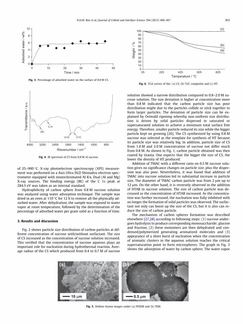
Fig. 3. Percentage of adsorbed water on the surface of 0.8 M CS.
OH
C=O C=C
Tran
smitt
ance
/ a.
u.
Wavenumber / cm—13200 2400 1800 1400 1000 6004000
C-H
Fig. 4. IR spectrum of CS from 0.8 M of sucrose.
0102030405060708090
100
25 225 425 625 825
Wei
ght
/ %
Temperature / °°C
(a)(b)
(c)
Fig. 6. TGA curves of the: (a) CS, (b) Ti/C composite and (c) HT.
N.H.M. Ran et al. / Journal of Colloid and Interface Science 394 (2013) 490–497 493
of 25–900 �C. X-ray photoelectron spectroscopy (XPS) measure-ment was performed on a Axis Ultra DLD Shimadzu electron spec-trometer equipped with monochromated Al Ka, Dual (Al and Mg)X-ray sources. The binding energy (BE) of the C 1s peak at284.5 eV was taken as an internal standard.
Hydrophilicity of carbon sphere from 0.8 M sucrose solutionwas analyzed using water adsorption technique. The sample wasdried in an oven at 110 �C for 12 h to remove all the physically ad-sorbed water. After dehydration, the sample was exposed to watervapor at room temperature, followed by the determination of thepercentage of adsorbed water per gram solid as a function of time.
3. Results and discussion
Fig. 2 shows particle size distribution of carbon particles at dif-ferent concentration of sucrose with/without surfactant. The sizeof CS increased as the concentration of sucrose solution increased.This verified that the concentration of sucrose aqueous plays animportant role for nucleation during hydrothermal reaction. Aver-age radius of the CS which produced from 0.4 to 0.7 M of sucrose
10 μm
(b(a)
Fig. 5. Hollow titania images un
solution showed a narrow distribution compared to 0.8–2.0 M su-crose solution. The size deviation is higher at concentration morethan 0.8 M indicated that the carbon particle size has poordistribution might due to the particles collide or stick together toform larger particles. The deviation of particle size can be ex-plained by Ostwald ripening whereby non-uniform size distribu-tion is driven by solid particles dispersed in saturated orsupersaturated solution to achieve a minimum total surface freeenergy. Therefore, smaller particle reduced its size while the biggerparticle kept on growing [26]. The CS synthesized by using 0.8 Msucrose was selected as the template for synthesis of HT becauseits particle size was relatively big. In addition, particle size of CSfrom 1.0 M and 2.0 M concentration of sucrose not differ muchfrom 0.8 M. As shown in Fig. 1, carbon particle obtained was thencoated by titania. One expects that the bigger the size of CS, thelower the density of HT produced.
Addition of TMAC with a different ratio on 0.5 M sucrose solu-tion gives no significance changes on particle size, plus the disper-sion was also poor. Nevertheless, it was found that addition ofTMAC into sucrose solution led to substantial increase in particlesize. The diameter of TMAC carbon particle was from 2 lm up to12 lm. On the other hand, it is reversely observed in the additionof HTAB in sucrose solution. The size of carbon particle was de-creased as the concentration of HTAB increased. As the concentra-tion was further increased, the nucleation was fully inhibited withno longer the formation of solid particles was observed. The surfac-tant not only can boost up the size of the CS, but it is also can re-duce the size of carbon particle.
The mechanism of carbon spheres formation was describedelsewhere [27,28] according to following steps: (1) sucrose under-goes hydrolysis to produce corresponding monosaccharide; glucoseand fructose, (2) these monomers are then dehydrated and con-densed/polymerized generating aromatized molecules and (3)appearance of a short burst of nucleation when the concentrationof aromatic clusters in the aqueous solution reaches the criticalsupersaturation point to form microspheres. The graph in Fig. 3shows the adsorption of water by carbon sphere. The water vapor
0.5 μμm
)
der (a) FESEM and (b) TEM.
1 μμm 500 nm
500 nm
(b)(a)
(c)
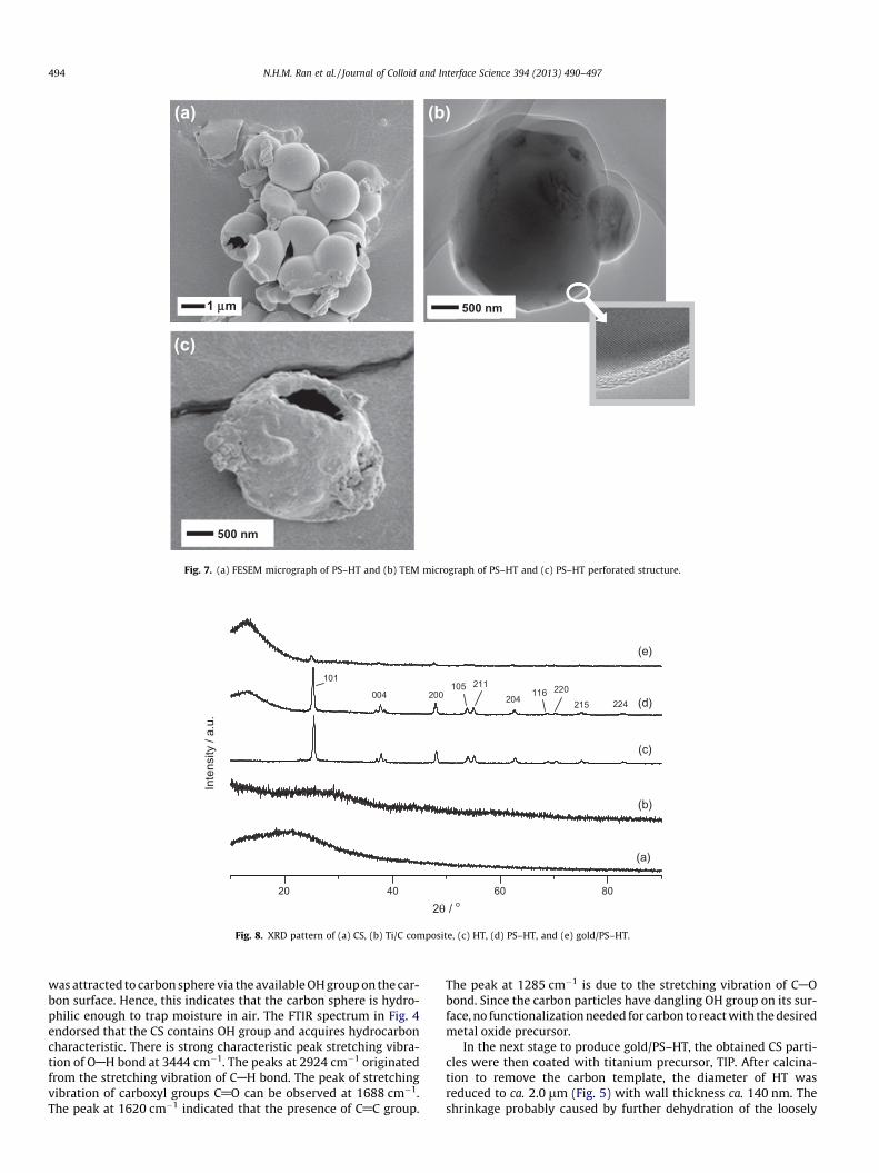
Fig. 7. (a) FESEM micrograph of PS–HT and (b) TEM micrograph of PS–HT and (c) PS–HT perforated structure.
(a)
(b)
(c)
(d)
(e)
Inte
nsity
/ a.
u.
101
004 200105 211
204116 220
215 224
2θ / o20 40 60 80
Fig. 8. XRD pattern of (a) CS, (b) Ti/C composite, (c) HT, (d) PS–HT, and (e) gold/PS–HT.
494 N.H.M. Ran et al. / Journal of Colloid and Interface Science 394 (2013) 490–497
was attracted to carbon sphere via the available OH group on the car-bon surface. Hence, this indicates that the carbon sphere is hydro-philic enough to trap moisture in air. The FTIR spectrum in Fig. 4endorsed that the CS contains OH group and acquires hydrocarboncharacteristic. There is strong characteristic peak stretching vibra-tion of OAH bond at 3444 cm�1. The peaks at 2924 cm�1 originatedfrom the stretching vibration of CAH bond. The peak of stretchingvibration of carboxyl groups C@O can be observed at 1688 cm�1.The peak at 1620 cm�1 indicated that the presence of C@C group.
The peak at 1285 cm�1 is due to the stretching vibration of CAObond. Since the carbon particles have dangling OH group on its sur-face, no functionalization needed for carbon to react with the desiredmetal oxide precursor.
In the next stage to produce gold/PS–HT, the obtained CS parti-cles were then coated with titanium precursor, TIP. After calcina-tion to remove the carbon template, the diameter of HT wasreduced to ca. 2.0 lm (Fig. 5) with wall thickness ca. 140 nm. Theshrinkage probably caused by further dehydration of the loosely

350 400 450 500 550 600 650 700 750 800
Ref
lect
ance
/ a.
u.
Wavelength / nm
(a)
(b)
(c)
Fig. 9. DR UV–Vis spectra of (a) HT, (b) PS–HT, and (c) gold/PS–HT.
50 45 40 35 30
20
10
0
25
15
5
gold 30/PS
gold 30/TiO2
gold 30/PS-
HT
gold 40/PS-
HT
gold 50/PS-
HT
gold 60/PS-
HT
stirring
static
TON
Liquid phase
Liquid phase
Catalyst
Fig. 11. The TON of liquid–gas boundary catalysis in oxidation of benzyl alcohol byusing molecular oxygen over gold/PS–HT, gold/PS beads and gold/TiO2 under staticand stirring conditions.
N.H.M. Ran et al. / Journal of Colloid and Interface Science 394 (2013) 490–497 495
cross-linked structure of the carbon spheres [29] which lead todensification of HT. The thermogravimetric curves of the carbonsphere (CS), titania–carbon composite (Ti/C composite) and hollowtitania (HT) are shown in Fig. 6. For CS and Ti/C composite, theweight loss region below 100 �C could be attributed to physicallyadsorbed water and residual of solvent in the sample and theweight loss at 350 �C could be resulted from decomposition of or-ganic compound. For HT, the straight line indicated that carbonparticle was completely removed by calcination.
As shown in Fig. 7a, it has been clearly observed that pore of HTwas fully covered by polystyrene as a ball-like material which ap-peared in smooth surface. The size of PS–HT is ca. 2.0 lm is notmuch different from HT. Wall thickness of polystyrene is ca. 50–200 nm (see Fig. 7b). A void inside the sphere cannot be observedunder TEM due to the thick wall of PS–HT. Fortunately, the layer ofpolystyrene and titania can be distinguished by differences in thecolor contrast. The crystalline phase of titania was clearly observedby the emerging of titania lattice under high-resolution TEM im-age. The outer layer indicates the amorphous phase of polystyrene.The particles of PS–HT which did not float on the surface of waterwere also analyzed using FESEM. Since it is difficult to determinethe density of PS–HT, the presence of perforated polystyrene-coated hollow titania (Fig. 7c) proved that the material containedan empty space within its sphere.
The crystalinity of CS, Ti/C composite, HT, PS–HT, and gold/PS–HT was confirmed by using XRD. Fig. 8a shows that CS produced byhydrothermal method displayed an amorphous phase since thereis no peak appears in the XRD pattern. Only a hump at 2h = 20�was observed. Amorphous titania was also obtained after the car-bon sphere was coated with titanium precursor to form tita-nium–carbon composite (see Fig. 8b). During the hydrothermalreaction, the pressure is created in an autoclave (autogeneous pres-sure) thus gives impact on the product. The hydrothermal reactionwhich takes place at moderate temperature in the 170–350 �Crange from sucrose produced amorphous carbon [28]. However,if the hydrothermal reaction takes place at elevated temperature,
(b(a)
50 nm
Fig. 10. Representative TEM images of (a) gold distribution and (b
saccharide-type of monomer will yield graphite-type of the carbon[30,31]. After calcination at high temperature, HT was transformedto anatase phase (see Fig. 8c). Since HT was covered with polysty-rene, the intensity of HT anatase peaks was reduced (see Fig. 8dand e).
Fig. 9 shows HT and PS–HT have the same reflectance in the vis-ible region which is 420 nm. On contrary, the gold/PS–HT showed ahypsochromic shift 390 nm and showed a marked decrease at540 nm which indicated the characteristic of gold nanoparticles[32]. Images of Au sputtered on the surface of the support and sizedistribution were presented in Fig. 10. Measurement of size distri-bution based on the images showed has mean particle size of ca.11.0 nm with broad distribution range 5–17 nm. High-resolutionimaging was performed on the gold particle and exhibited latticefringes 2.53 Å. There is no change in the size of gold particles asthe sputtering time increasing. The different is only the amountof gold deposited on the PS–HT. This observation is similar to theprevious report [33].
Fig. 11 shows the turnover number (TON) of the catalytic reac-tion of the oxidation of benzaldehyde by molecular oxygen understirring and static conditions. The TON was determined based onthe amount of gold nanoparticles deposited on PS–HT. The reactionof gold/PS–HT was also compared with gold 30/PS and gold 30/TiO2. The gold 30/PS showed a relatively low production of
)
2 nm
) lattice fringes appearance of 1% Au loading on gold/PS–HT.

polystyrene
hollow titania
H
O
benzaldehyde
O2
Liquid phase
Gas phase
Catalyst located at liquid-gas phase boundary
gold
OH
benzyl alcohol
Active catalytic site
Fig. 12. Proposed model of the gold/PS–HT phase-boundary catalyst and the catalytic pathway of benzaldehyde formation over active Au-site.
Fig. 13. XPS spectrum of gold nanoparticles deposited on PS–HT.
496 N.H.M. Ran et al. / Journal of Colloid and Interface Science 394 (2013) 490–497
benzaldehyde in both stirring and static condition. This presum-ably due to the location of polystyrene beads is at the bottom ofthe mixture which makes it hard to be accessed by oxygen gas.Gold 30/PS was proven to be less active for this catalysis. The gold30/TiO2 showed better production of benzaldehyde, yet the PS–HTwith gold catalysts still performed better. As can be seen, stirringcondition contributes higher yield of benzaldehyde than static con-dition. The stirring circumstance could enhance the reaction byallowing more gaseous reactants to reach the catalyst surface be-cause it has overcome the gas–liquid and liquid–solid mass trans-fer resistance. Thus, the interfacial interaction increases betweenthe catalyst and the reactant since the gas can diffuse to the liquidto increase the contact area for oxidation. On the other hand, understatic condition, the degree of interaction between the gold andsubstrates is constrained, though it showed good catalytic activity
under static condition in gold 40/PS–HT and gold 50/PS–HT.According to production of benzaldyhyde, the TON decreased asthe gold loading increased. An increase in the loading of gold nano-particles could result in a low yield of product due to the gold ex-isted as a bulk [34]. It can be proposed that the higher TON of gold30/PS–HT under stirring condition among the others is due to thehigh availability of effective active sites to catalyze the oxidationreaction. By the increase in sputtering time, the gold particles tendto agglomerate to form large clusters hence reduced the activity ofthe catalyst. Besides, the oxidation state of gold is believed hascontributed to the enhancement of the TON which will be ex-plained in the next paragraph.
Proposed model of phase-boundary catalyst and its catalyticpathway is depicted in Fig. 12. The active Au-site is located atthe interphase of organic and gas phases. During the reaction,

Fig. 14. Dispersion comparison of (a) gold/PS–HT, (b) PS beads, (c) HT, and (d) TiO2
in water.
N.H.M. Ran et al. / Journal of Colloid and Interface Science 394 (2013) 490–497 497
the substrate and O2 that are in contact with Au will be consumedthus created the concentration gradient. The continuous suppliesof the substrates from its bulk act as a driving force which enablesthe reaction to proceed without enforcing the mass transfer to oc-cur [2]. Oxygen can dissolve in water allowing the active site in theliquid phase to carry out the reaction but not active as the activesite located at the boundary.
The oxidation state of gold in gold 30/PS–HT was analyzed byXPS technique [24], and the spectrum of Au 4f region is presentedin Fig. 13. It revealed that the traces of Au0, Au+, and Au3+ contentsin the sample. The peaks at 82.45 and 86.15 eV correspond to Au4f7/2 and 4f5/2 species. Peaks at 84.45 and 88.25 eV correspond toAu3+ 4f7/2 and 4f5/2, and those at 83.35 and 87.35 eV correspondto Au+ 4f7/2 and 4f5/2. Au3+ was observed to have the largest peakarea at 4f7/2 and Au+ has the largest peak area at 4f5/2, while thepeaks of Au0 in 4f7/2 and 4f5/2 show the smallest peak area. Sincethe gold was sputtered from a gold target disk, the transition ofthe gold should be Au0. It has been reported that Au0 is the mostactive species in the catalytic activity of benzyl alcohol comparedto oxidized gold [35]. This might be the reason of low catalyticactivity of gold/polystyrene-coated hollow titania.
Fig. 14 shows the apparent distribution of gold/PS–HT, gold/PSbeads, HT, and TiO2 in water. It was observed that the gold/PS–HT was effectively floated on the surface of water, TiO2 was well-dispersed in water, and gold/PS and HT settle down to the bottomof the bottle. The higher density of the polystyrene beads(1.05 g cm�3) than water (1.00 g cm�3) could be the reason whythe particles of polystyrene settle down to the bottom of the bottle.It was also observed that HT sinks faster than the TiO2 due to itsperforated structure. In gold/PS–HT case, only ca. 30% of it can befloated on water. The powder of gold/PS–HT was immediatelyspread on water after being added and later formed a tiny layerof particles which remains floating until now.
4. Conclusion
In conclusion, gold/polystyrene-coated hollow titania can bemade by using sucrose, titanium(IV) isopropoxide, and styrene as
precursors. Hollow titania was simply synthesized by using carbonspheres as a template. Polystyrene was coated onto hollow titaniato prevent water from penetrating into the system and making itfloat on the water. It is observed that, after polystyrene-coated hol-low titania was sputtered with gold nanoparticles, this materialwas active in liquid–gas boundary catalysis in oxidation of benzylalcohol by using molecular oxygen.
Acknowledgments
We gratefully acknowledge the funding from The Ministry ofScience, Technology and Innovation (MOSTI) Malaysia, underScienceFund Grant, The Ministry of Higher Education (MOHE)Malaysia, under Fundamental Research Grant Scheme, and Univer-siti Teknologi Malaysia (UTM), under Research University Grant.N.H.M.R thanks National Science Fellowship, MOSTI for financialsupport.
References
[1] H. Nur, S. Ikeda, B. Ohtani, Chem. Commun. 22 (2000) 2235–2236.[2] H. Nur, S. Ikeda, B. Ohtani, J. Catal. 204 (2001) 402–408.[3] H. Nur, S. Ikeda, B. Ohtani, React. Kinet. Catal. L 82 (2004) 255–261.[4] H. Nur, S. Ikeda, B. Ohtani, J. Braz. Chem. Soc. 15 (2004) 719–724.[5] H. Nur, N.Y. Hau, I.I. Misnon, H. Hamdan, M.N.M. Muhid, Mater. Lett 60 (2006)
2274–2277.[6] S. Ikeda, H. Nur, T. Sawadaishi, K. Ijiro, M. Shimomura, B. Ohtani, Langmuir 17
(2001) 7976–7979.[7] G.J. Brink, I.W.C.E. Arends, R.A. Sheldon, Science 287 (2000) 1636–1639.[8] I.E. Markó, P.R. Giles, M. Tsukazaki, S.M. Brown, C.J. Urch, Science 274 (1996)
2044–2046.[9] S.R. Cicco, M. Latronico, P. Mastrorilli, G.P. Suranna, C.F. Nobile, J. Mol. Catal. A:
Chem. 165 (2001) 135–140.[10] A.F. Lee, J.J. Gee, H.J. Theyers, Green Chem. 2 (2000) 279–282.[11] S. Yu, H. Liu, J. Yu, J. Catal. 249 (2007) 59–66.[12] Y. Ao, J. Xu, D. Fu, C. Yuan, Catal. Commun. 9 (2008) 2574–2577.[13] J. Yu, W. Liu, H. Yu, Cryst. Growth Des. 8 (2008) 930–934.[14] F. Magalhães, R.M. Lago, Sol. Energy 83 (2009) 1521–1526.[15] L.C.R. Machado, C.B. Torchia, R.M. Lago, Catal. Commun. 7 (2006) 538–541.[16] H. Han, R. Bai, Ind. Eng. Chem. Res. 48 (2009) 2891–2898.[17] H. Bala, Y. Yu, Y. Zhang, Mater. Lett. 62 (2008) 2070–2073.[18] W. Liu, S. Roy, X. Fu, AIChE J. 51 (2005) 2285–2297.[19] A.S.K. Hashmi, G.J. Hutchings, Angew. Chem. Int. Ed. 45 (2006) 7896–7936.[20] M. Haruta, Catal. Today 36 (1997) 153–166.[21] K. Sayo, S. Deki, S. Hayashi, J. Mater. Chem. 9 (1999) 937–942.[22] A. Martin, U. Bentrup, A. Brückner, B. Lücke, Catal. Lett. 59 (1999) 61–65.[23] V.R. Choudhary, P.A. Chaudhari, V.S. Narkhede, Catal. Commun. 4 (2003) 171–
175.[24] N. Dimitratos, A. Villa, D. Wang, F. Porta, D. Su, L. Prati, J. Catal. 244 (2006)
113–121.[25] M. Zheng, J. Cao, X. Chang, J. Wang, J. Liu, X. Ma, Mater. Lett. 60 (2006) 2991–
2993.[26] C.S. Cundy, P.A. Cox, Micropor. Mesopor. Mater. 82 (2006) 1–78.[27] M. Zheng, Y. Liu, Y. Xiao, Y. Zhu, Q. Guan, D. Yuan, J. Zhang, J. Phys. Chem. C 113
(2009) 8455–8459.[28] M. Sevilla, A.B. Fuertes, Chem. Eur. J. 15 (2009) 4195–4203.[29] X. Sun, Y. Li, Angew. Chem. Int. Ed. 43 (2004) 3827–3831.[30] Y. Mi, W. Hu, Y. Dan, Y. Liu, Mater. Lett. 62 (2008) 1194–1196.[31] D. Zhang, Y. Hao, Y. Ma, H. Feng, Appl. Surf. Sci. 258 (2012) 2510–2514.[32] N.L. Lala, T.C. Deivaraj, J.Y. Lee, Colloid Surf. A 269 (2005) 119–124.[33] X. Zhou, Q. Wei, K. Sun, L. Wang, Appl. Phys. Lett. 94 (2009) 133107–133107-3.[34] M. Comotti, C.D. Pina, R. Matarrese, M. Rossi, Angew. Chem. 116 (2004) 5936–
5939.[35] G. Zhan, J. Huang, M. Du, D. Sun, I. Abdul-Rauf, W. Lin, Y. Hong, Q. Li, Chem.
Eng. J. 187 (2012) 232–238.