Joints and Pains of Hydraulic Cylinder - Wipro infra and field testing presented .Accelerated to...
16
Joints and Pains of Hydraulic Cylinder Mohan kumar L , Jayakeerthi S, Ganesh K C, Ramesh D. Wipro Infrastructure Engineering Ltd. Bangalore 58. Abstract "Enhanced solutions to achieve long painless life of Hydraulic cylinders and hence end equipment". Hydraulic cylinder is the ‘muscle of fluid power’ linking load, structure and hydraulics. It will act like rigid steel yet flexes like fluid accomplishing the duty and task like the knees and arms which do all walking and working hydraulic cylinders perform their duty relentlessly straining and damaging joints. No other member in the machine experiences the modes a cylinder encounters viz., - buckling - bursting - bending - bulging - twisting, shearing, tearing, tension compression …………. The construction, cross-section, steel in all its composition and treatment along with functional surfaces do call very high degree of super precision design and manufacturing – with culture of its own. Aptly over the years “Hydraulic Grade’ is established in terms of - material – castings, forgings, tubes, rods etc. - heat treatment - surface coating treatments - Hydraulic tolerances, forms & finish. Anatomy of hydraulic cylinder reveals many critical members and joints. - impacting & high load motion surfaces - welded joints to resist hydraulic pressure shocks, peaks and mechanical impacts - prestressed threaded joints integrity and tactness under milli-second/fraction of m sec shocks and peaks - friction welded joint survive tension, twisting, bending, compression and sheer loads - barrels – not just pressure vessels but under pressure hoop expansion maintains cylindrical bore for piston operation - rods – take all the abuses direct/side loads Each of these members or joints are subjected to both static and dynamic stresses – high or low cycle fatigue leading to damage hence fatigue failure. This paper describes various critical joints of hydraulic cylinder & discusses - joint construction - material and design aspects - static and transient loading aspects - joint analysis and - cyclic load testing of joints Systematic approach in terms of understanding the loading, design, materials, stress analysis, laboratory and field testing presented .Accelerated to Highly accelerated test methods are discussed
Transcript of Joints and Pains of Hydraulic Cylinder - Wipro infra and field testing presented .Accelerated to...
Joints and Pains of Hydraulic Cylinder
Mohan kumar L , Jayakeerthi S, Ganesh K C, Ramesh D.Wipro Infrastructure Engineering Ltd.
Bangalore 58.
Abstract
"Enhanced solutions to achieve long painless life of Hydraulic cylinders and hence end equipment".
Hydraulic cylinder is the ‘muscle of fluid power’ linking load, structure and hydraulics. It will act likerigid steel yet flexes like fluid accomplishing the duty and task like the knees and arms which do allwalking and working hydraulic cylinders perform their duty relentlessly straining and damagingjoints.
No other member in the machine experiences the modes a cylinder encounters viz.,- buckling- bursting- bending- bulging- twisting, shearing, tearing, tension compression ………….
The construction, cross-section, steel in all its composition and treatment along with functionalsurfaces do call very high degree of super precision design and manufacturing – with culture of itsown.
Aptly over the years “Hydraulic Grade’ is established in terms of- material – castings, forgings, tubes, rods etc.- heat treatment- surface coating treatments- Hydraulic tolerances, forms & finish.
Anatomy of hydraulic cylinder reveals many critical members and joints.- impacting & high load motion surfaces- welded joints to resist hydraulic pressure shocks, peaks and mechanical impacts- prestressed threaded joints integrity and tactness under milli-second/fraction of m sec shocks and
peaks- friction welded joint survive tension, twisting, bending, compression and sheer loads- barrels – not just pressure vessels but under pressure hoop expansion maintains cylindrical bore for
piston operation- rods – take all the abuses direct/side loads
Each of these members or joints are subjected to both static and dynamic stresses – high orlow cycle fatigue leading to damage hence fatigue failure.
This paper describes various critical joints of hydraulic cylinder & discusses- joint construction- material and design aspects- static and transient loading aspects- joint analysis and- cyclic load testing of joints
Systematic approach in terms of understanding the loading, design, materials, stress analysis,laboratory and field testing presented .Accelerated to Highly accelerated test methods are discussed

1.0 Introduction
1.1 Muscle and Motion behind productive &performing machines
Ever since Blaise Pascal, Joseph Brahma,Bernoulli and others contributed to FluidSystems and Energy, it is in the last century wesaw host of machines and innumerableapplications deployed hydraulic powertransmissions. Some of them (popular ones) areMachines & Equipments that need power &precision.
a. Construction Machines
b.
c.
T
Ga
d.
e. Aircraft's
Civil Military
f. Plant
Steel Plant Cement Plant
Excavator
Dumper
Industrial E
Forklift
Truck Hydr
ipper Underbod
rbage Compacto
Agricultura
Tractor
Tractor
Backhoe Loader Tractor
Grader
quipments & Machines
Injection Moulding
In all the above the power conversion andtransmission from the engine / electric motor to the
Fig. 1 - Machines
2
Drill RigCrane
aulics
y Tipper Frontend Dumper Placer
r Truck mounted crane Car Carrier
l
Harvestor
Forestry
poinThiof c
The7 M420
1.2
Thein th
The
The
t of application, completely fluid / oil linked.s has made the entire design flexible with easeontrol of energy.
se machines operate in the pressure rangePa (approx. 70 Kgf/cm2) to 42 Mpa (approx.
Kgf/cm2) & velocity range 0.1 to 1 m/sec max.
Elements of Hydraulic Power Transmission
typical power transmission system is illustratede diagram.
primary elements are :• engine / electric motor driven pump• control valves• actuators (cylinders / motors)
secondary elements are
• conductors (Pipes, Hoses)• conditioners (Filters, Heat exchangers)• oil storage / tank with accessories

F
1
Tp
ig. 2- Elements of hydraulic power transmission
.3 Roll of Hydraulic cylinder
asks – each of the above machines demandrecise actions based on requirements viz.,
- lifting- rotating- turning- steering- digging- swiveling- hoisting- pressing ……..
2.0 Hydraulic Cylinder & Working Principle
Hydraulic cylinder consists of -
Barrel / tube mostly ‘stationary’ havingprecision machined & super finished bore(honed / burnished)
Rod / Ram mostly ‘moving’ having precisiongrinding followed by super finishing
Piston and ram rod seals provide sealingbetween chambers containing pressure yetallowing motion – thus accomplishes Force &Motion
Bearings on piston & rod / ram facilitates thenecessary motion between bore-piston andcover & rod.
Hydraulic oil ports for extension & retraction
2.1 Working Principle
Hydraulic cylinder is a ‘linear actuator’ whichprovides linear motion converting hydraulic energyinto mechanical power.
The pressure and flow in the chamber get convertedto force and motion at the load point.
Construction and elements of a cylinder shownbelow
3
Fig. 3 – Applications
Fig. 4 - Construction of cylinder
2.2 Extension
During extension, the full area takes on the fullpressure and the rod side is connected to return linehaving low pressure.
The oil flowing into the piston side increases thepressure to equate the load and additionalpressurized oil flow pushes the piston impartingmotion

4
Fig5: cylinder crossection--completely in/retracted-neutral- completely extended
2.3 Retraction
During retraction, the rod side area (annular)takes on the full pressure and hydraulic-mechanical work is the same as explained inextension.
2.4 Action and Reaction
The function of the cylinder is to give linearactuation to an external mass. This is achievedby inversion of the mechanism i.e., by fixing anyone end of the cylinder.
The cylinder experiences various kinds of forcesand reactions during extension and retractionwhich is represented in the figure below.
Fig. 6 - Hydraulic cylinder action and reaction
When oil builds the pressure inside the cylinder?When there is an external load acting on thecylinder end (Action) then the internal oil within the cylinder builds the pressure (Reactionforce) in order to oppose the push or pull, Thenit is said to be work done.
2.5 Cross section and Critical areas in aHydraulic Cylinder
Hydraulic cylinders are most important andcritical members among the mechanical loadcarrying members. There are various joints and
parts within the hydraulic cylinder that aresubjected to various kinds of loads and stresses. Thecriticality of each of the joints along with stressesare being discussed here.
The hydraulic cylinders consists of many sectionsand joints that are critical to failure. The criticaljoints include Cap cover tube weld joint, Cap covershear zone, piston shear zone, tube, piston rod TubeHEC threaded joint, Piston rod-rod eye weld joint,and rod eye.The table shows what are the sections why thesesections are going to fail and what is the remedy forthe joint failure.
What? Why? Remedy?CAP cover- tubeweld joint
Tensile - Crackpropagation SCF
Tensile stress,Fatigue crack
Tube Bursting Hoop stressPistonrod- rodeye Shearing Shear stressPiston nut thread shearing Shear stressTube –piston rod Surface scoring Side load
buckling
The above mention what –why joints are depictedin the fig below.
Fig.7 - Hydraulic cylinder critical sections and stresses.
Fig.7a - Hydraulic cylinder critical sections andstresses.
2.6 Force flow diagrams of Double actingHydraulic CylinderThe basic function of a hydraulic cylinder isperformed with two functional end stages,Extension and Retraction. Action and reactionforces during the two stages are very complex anddynamic in nature, for the purpose of theoreticalanalogy force flow diagram during the two

5
functional stages of hydraulic cylinder is infigure(8) and figure(9).
Fig.8- Forces acting on Hydraulic Cylinder – extension
Fig.9-forces acting on Hydraulic Cylinder – Retraction.
The forces acting within the Hydraulic Cylinderpushes the piston rod which results in fullextension of the piston rod. When the Hydrauliccylinder is completely extended a oppositereaction force acts on the rod eye which allowsthe cylinder to retract and return to its originalposition.
When there is a force pulling the rod end duringfull extension of cylinder as in fig (8) in anunhealthy situation of hydraulic cylinder. In thiscondition all the joints and connections willexperiences tension-tension forces that lead toearly failures which is shown in fig(9) there is anexternal force that acting towards cap end coverend of cylinder that grounds the forces bybuilding the pressure inside hydraulic cylinderstated as healthy state of the hydraulic cylinder.All these worst conditions are used to study jointstrength in this paper.The below figure shows the force flow in atypical telescopic cylinder. This type of cylinderis used in front end tipper used to tip the tipperbody.
Fig 10 : Stress/ Force flow in Telescopic cylinder
Stress/ Force flow in the pipe: Pipe used to carryhydraulic oil in to the cylinder.
Fig 11-Stress/ Force flow in a pipe
2.7 Load and induced pressure levels inHydraulic cylindersThe pressure of the hydraulic fluid induces stressesinside the hydraulic cylinder when extension andretraction of the hydraulic cylinder takes place. Theback pressure inside the hydraulic cylinder inducespressure induced stresses. The pressure developedwithin the tube will give rise to hoop stress andbending of piston rod when the critical bucklingload is being exceeded
For the theoretical estimation of stress and life, thedynamic time varying loads are simplified into loadspectrum that defines series of bands of constantload levels and the number of times that each loadband is experienced. The typical load bandconsidered for analogy is as shown in fig below .
Fig 12 : Simplified load spectrum
2.8 Pressure Vessels - Thin Wall PressureVessels
Thin wall pressure vessels are in fairly commonuse. We would like to consider two specific types.Cylindrical pressure vessels, and spherical pressurevessels. By thin wall pressure vessel we will mean acontainer whose wall thickness is less than 1/10 ofthe radius of the container. Under this condition, thestress in the wall may be considered uniform.

6
We first look at a cylindrical pressure vesselshown in Diagram 1, where we have cut a crosssection of the vessel, and have shown the forcesdue to the internal pressure, and the balancingforces due to the longitudinal stress whichdevelops in the vessel walls.
Fig 13 : Thin walled pressure vessel.
To determine the relationship for the transversestress, often called the hoop stress, we use thesame approach, but first cut the cylinderlengthwise as shown in fig 36.
Fig 14 : forces in a pressure vessel
Hoop stresses:
σH= P R / t
P = internal pressure in cylinder;R = radius of cylinder,t= wall thickness.
We note that the hoop stress is twice the value ofthe longitudinal stress, and is normally thelimiting factor. The vessel does not have to be aperfect cylinder. In any thin wall pressure vesselin which the pressure is uniform and which has acylindrical section, the stress in the cylindricalsection is given by the relationships above
2.9 Columns and bucklingWhen we speak of columns (and buckling) we aretalking about members loaded in compression,often axially loaded, although columns may beloaded eccentrically. We also tend to think ofcolumns as vertical members, however, theformulas we will utilize also apply to horizontalcompression members, or to compression membersin general. For instance, compression members of atruss may be considered to be columns pinned ateach end point
Columns may be divided into three general types:Short Columns, Intermediate Columns, and LongColumns. The distinction between types of columnsis not well defined, but a generally acceptedmeasure is based on the Slenderness Ratio. TheSlenderness Ratio is the (effective) length of thecolumn divided by its radius of gyration.
3 Life cycle and fatigue considerationsFatigue is the progressive localized permanentstructural change that occurs in materials subjectedto fluctuating stresses that may result in cracks orfracture after sufficient number of cycles.
3.1 Fatigue life prediction :Fatigue life of any specimen or structure is thenumber of stress (strain) cycles required to causethe failure.
3.2 Stress – strain diagrams:The behavior of materials and their suitability forengineering purposes can be obtained byconducting tensile test and plotting the relationshipbetween stress and strain.
Fig. 15 – stress strain diagrams for low carbon steeland heat treated colddrawn steel.
3.3 Low cycle and high cycle fatigue :In low cycle fatigue significant plastic strainingoccurs. Low cycle fatigue involves large cycleswith significant amounts of plastic deformationwith relatively short life.
7
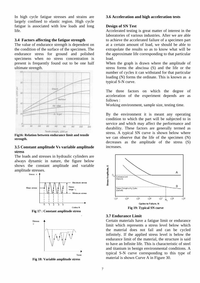
In high cycle fatigue stresses and strains arelargely confined to elastic region. High cyclefatigue is associated with low loads and longlife.
3.4 Factors affecting the fatigue strengthThe value of endurance strength is dependent onthe condition of the surface of the specimen. Theendurance stress for ground and polishedspecimens when no stress concentration ispresent is frequently found out to be one halfultimate strength.
Fig16: Relation between endurance limit and tensilestrength.
3.5 Constant amplitude Vs variable amplitudestressThe loads and stresses in hydraulic cylinders arealways dynamic in nature, the figure belowshows the constant amplitude and variableamplitude stresses.
Fig 17 : Constant amplitude stress
Fig 18: Variable amplitude stress
3.6 Acceleration and high acceleration tests
Design of SN TestAccelerated testing is great matter of interest in thelaboratories of various industries. After we are ableto achieve the accelerated failure of a specimen partat a certain amount of load, we should be able toextrapolate the results so as to know what will bethe approximate life corresponding to that particularload.When the graph is drawn where the amplitude ofstress forms the abscissa (S) and the life or thenumber of cycles it can withstand for that particularloading (N) forms the ordinate. This is known as atypical S-N curve.
The three factors on which the degree ofacceleration of the experiment depends are asfollows :Working environment, sample size, testing time.
By the environment it is meant any operatingcondition to which the part will be subjected to inservice and which may affect the performance anddurability. These factors are generally termed asstress. A typical SN curve is shown below wherewe can observe that the life of the specimen (N)decreases as the amplitude of the stress (S)increases.
Fig 19: Typical SN curve
3.7 Endurance LimitCertain materials have a fatigue limit or endurancelimit which represents a stress level below whichthe material does not fail and can be cycledinfinitely. If the applied stress level is below theendurance limit of the material, the structure is saidto have an Infinite life. This is characteristic of steeland titanium in benign environmental conditions. Atypical S-N curve corresponding to this type ofmaterial is shown Curve A in Figure 30.
8
The factors that influences the endurance limitinclude Surface Finish ,Temperature StressConcentration Notch Sensitivity ,Size,Environment Reliability.
3.8 Fatigue RatioThrough many years of experience, empiricalrelations between fatigue and tensile propertieshave been developed. Although theserelationships are very general, they remainuseful for engineers in assessing preliminaryfatigue performance.The ratio of the endurance limit Se to theultimate strength Su of a material is called thefatigue ratio. It has values that range from 0.25to 0.60, depending on the material
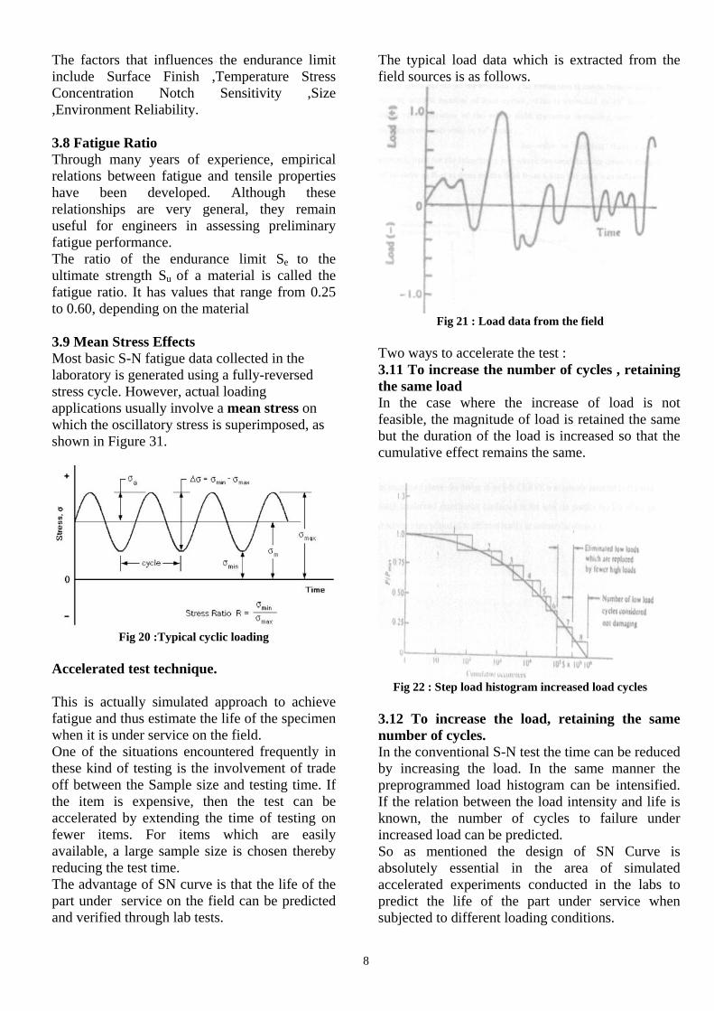
3.9 Mean Stress EffectsMost basic S-N fatigue data collected in thelaboratory is generated using a fully-reversedstress cycle. However, actual loadingapplications usually involve a mean stress onwhich the oscillatory stress is superimposed, asshown in Figure 31.
Fig 20 :Typical cyclic loading
Accelerated test technique.
This is actually simulated approach to achievefatigue and thus estimate the life of the specimenwhen it is under service on the field.One of the situations encountered frequently inthese kind of testing is the involvement of tradeoff between the Sample size and testing time. Ifthe item is expensive, then the test can beaccelerated by extending the time of testing onfewer items. For items which are easilyavailable, a large sample size is chosen therebyreducing the test time.The advantage of SN curve is that the life of thepart under service on the field can be predictedand verified through lab tests.
The typical load data which is extracted from thefield sources is as follows.
Fig 21 : Load data from the field
Two ways to accelerate the test :3.11 To increase the number of cycles , retainingthe same loadIn the case where the increase of load is notfeasible, the magnitude of load is retained the samebut the duration of the load is increased so that thecumulative effect remains the same.
Fig 22 : Step load histogram increased load cycles
3.12 To increase the load, retaining the samenumber of cycles.In the conventional S-N test the time can be reducedby increasing the load. In the same manner thepreprogrammed load histogram can be intensified.If the relation between the load intensity and life isknown, the number of cycles to failure underincreased load can be predicted.So as mentioned the design of SN Curve isabsolutely essential in the area of simulatedaccelerated experiments conducted in the labs topredict the life of the part under service whensubjected to different loading conditions.

9
Fig 23: stepload histogram with increased load
4 Theoretical estimation of stresses and lifeevaluations:Welded jointThe joining of two or more metallic componentsby introducing fused metal(welding rod)into afillet between the components or by raising thetemperature of their surfaces or edges to thefusion temperature and applying pressure iscalled a welded joint.
Fig 24 : welded joints –types.
Figure 33 shows three types of welded joints. Ina lap weld ,the edges of a plate are lapped oneover the other and the edge of one is welded tothe surface of the other. In a butt weld, the edgeof one plate is brought in line with the edge of asecond plate and the joint is filled with weldingmetal or the two edges are resistance-heated andpressed together to fuse. For a fillet weld ,theedge of one plate is brought against the surfaceof another not in the same plane and weldingmetal is fused in the corner between the twoplates, thus forming a fillet. The joint can bewelded on one or both sides.
4.1 Theoretical life estimation :Soderbergs-Goodmans approach :
Fig 25: soderberg and Goodmans approach
Soderberg lineIf the point of the combined stress is below thesoderberg line then the component will not fail.This is a very conservative criteria based on thematerial yield point Syt.To establish the factor of safety relative to thesoderberg criteria.
kfσamp σmean 1 + = Se Syt Nf
Goodman lineIf the point of the combined stress is below therelevant Goodman line then the component will notfail. This is a less conservative criteria based on thematerial ultimate strength yield point Sut.
kfσamp σmean 1 + = Se Sut Nf
Gerber's lineIf the point of the combined stress is below theGerber's line then the component will not fail. Thisis a less conservative approach based on thematerial ultimate strength Sut.To establish the fos relative to the Gerber's criteria.
Nfkfσamp (Nfσmean )2 1 + = Se (Sut)2 Nf

10
Where Se= the modified fatigue strength Sut = the ultimate tensile strength Syt = the yield tensile strength Nf = fos applicable for fatigue.
4.2 Basquin's relations
The theoretical life estimation is done by usingBasquin's relation. It is found to 68550 cyclesand experimental life of the specimen is 42000cycles.Theoretical estimation:The life is calculated by using the relation.
B= log(σe)-log(0.9σu)/3
A=σe/10(6B)
applying Basquin's equation
N=(σr/A)1/B
WhereN= No of cycles to failureA and B= Basquin coefficientsσt= Tensile strength of the specimenσe= Endurance limit of specimenσu= Ultimate tensile strengthσt= Tensile strength of the specimenσe= Endurance limit of the specimenσu= Ultimate strength of the specimenσr= Range stress stress
5. Stress and FEA of critical areasCase studies of some of stress and FEA ofcritical areas are discussed in the section.The critical areas of hydraulic cylinder are asdepicted in picture shown in fig(7).
5.1 Analysis of Cap cover Tube welded JointIn a hydraulic cylinder cap end cover and tubeare joined by a welding technique. This cap endcover tube-welding joint is one such section thataffects the quality of a hydraulic cylinder.Here an existing design for the welded section isstudied and an alternate design solution is foundto reduce the stresses coming on to the weldgroove and thus increases life of cylinder.The function of an arm cylinder is to actuate thearm of a Backhoe Loader for excavatingoperation (Digging operation).Arm cylinder is mounted on the structure of aBackhoe loader with clevis/ cap end cover androd
eye mountings. Clevis/ cap end side of the cylinderis mounted to boom and rod eye to the arm of theequipment. The figure below shows differentialcylinder mounted on to the backhoe loader.
Fig 26 : position of arm cylinder inbackhoe loader.
Failure analysis.The cap end cover and tube are joined by a U-groove by welded technique. When there is a hoopload is acting on the tube it tends to that cause thecrack and growth of pre existing crack.
Fig27 : weld failure zone and 3d model
AnalysisModels considered are cap end cover, tube and theweld joint as per the WIPRO standards.Figure 20 shows the 3D model considered foranalysis. The model considered is a part of thecylinder. The two halves of the weld grooves areconsidered for analysis and comparison is beingmade accordingly.
Fig 28 : weld groove root jointConclusionThe two designs considered for analysis areCase 1 Design 1.Case 2 Design 2.Maximum Von Mises stress values and its locationin each case is shown in table 1 below.
11
Table 1 : maximum stress values
Conclusion and resultsFrom the above we can conclude that the resultsof the validation and the theoritical results matchas per the stress values.
5.2. Tube flaring analysis at HEC threadedportionIn a hydraulic cylinder tube and head end cover(HEC) are fastened by a threaded joint, thus helpin movement of piston rod through head endcover. Due to the pressure load and mechanicalforce the tube tend to flare off at this threadedpotion. This flaring of tube is studied and acosteffective simple solution is presented here.
Background
Fig 29 : stress concentration in threads
Figure 29 shows the stress concentration in thethreaded region of nut and bolt. Stressconcentration appears in the first threads, whichare heavier, loaded than the distant ones andresults in non-uniform stress distribution. This isthe case when the load applied on the bolt in thedownward direction as shown in the figure 27.When the load is made upwards nut body willflare off in the direction of "x", radial outwarddirection. This indicates that the last threaddoesn't participate in taking the load due toflaring of nut.
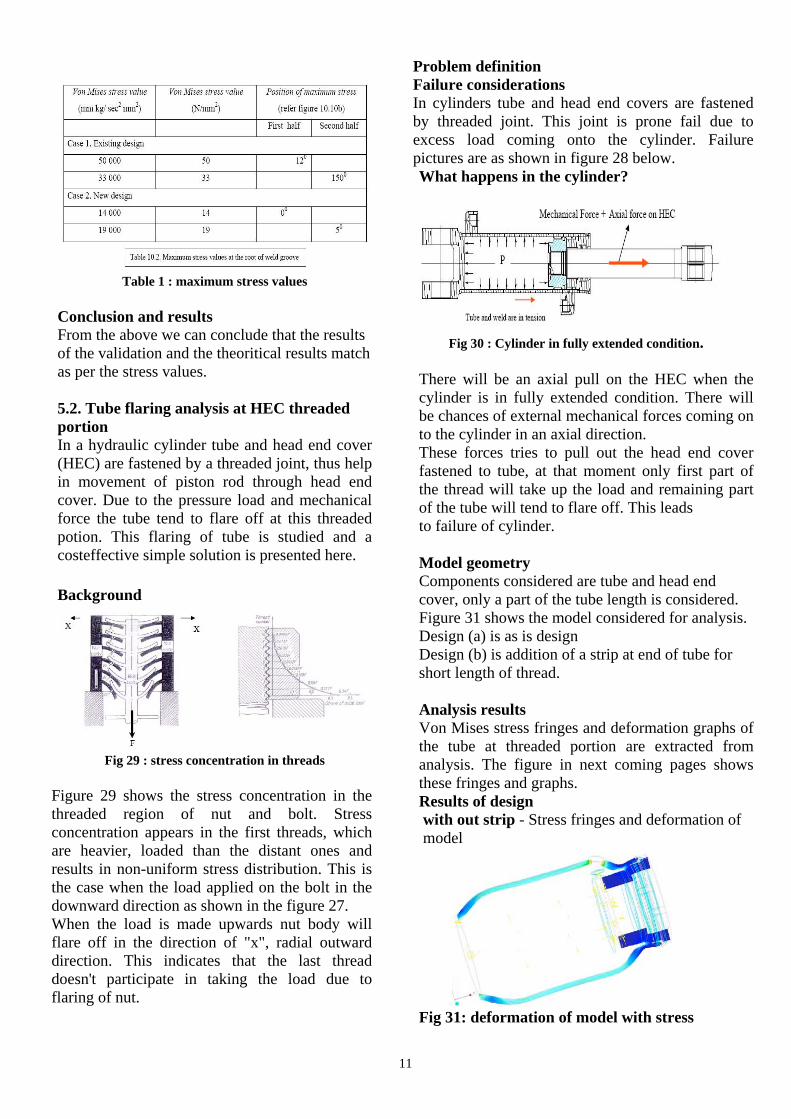
Problem definitionFailure considerationsIn cylinders tube and head end covers are fastenedby threaded joint. This joint is prone fail due toexcess load coming onto the cylinder. Failurepictures are as shown in figure 28 below.What happens in the cylinder?
Fig 30 : Cylinder in fully extended condition.
There will be an axial pull on the HEC when thecylinder is in fully extended condition. There willbe chances of external mechanical forces coming onto the cylinder in an axial direction.These forces tries to pull out the head end coverfastened to tube, at that moment only first part ofthe thread will take up the load and remaining partof the tube will tend to flare off. This leadsto failure of cylinder.
Model geometryComponents considered are tube and head endcover, only a part of the tube length is considered.Figure 31 shows the model considered for analysis.Design (a) is as is designDesign (b) is addition of a strip at end of tube forshort length of thread.
Analysis resultsVon Mises stress fringes and deformation graphs ofthe tube at threaded portion are extracted fromanalysis. The figure in next coming pages showsthese fringes and graphs.Results of designwith out strip - Stress fringes and deformation ofmodel
Fig 31: deformation of model with stress

12
Analysed for with and without strips optimalplacement and length the strip is found.
Fig 32 : Enlarged view of deformation of model
Fig33 : Deformation case without strip
Fig 34 : Deformation case with strip
ConclusionsAnalysis study is conducted with two cases,Design (a) without considering strip.Design (b) with considering strip.The flaring of tube is avoided by consideringcase 2 i.e., Design (b) with strip case. It isobserved that even with application of load thereis a positive thrust on the HEC, so that flaring isavoided. Due to presence of positive locking betweentube and HEC, entire length of the thread willtake up the load hence shear of thread isavoided.
5.3 Piston Rod thread under-cut analysisPiston rod thread under-cut is one of the criticalareas of hydraulic cylinder that is prone tofailure. An optimum radius is required to reducethe stresses at the undercut portion. Optimumradius is found by considering different radiusvalues at the undercut portion to reduce stresses.ResultsAnalysis is carried for seven radius values. Theradius values and corresponding stress values arepresented in the table
Fig 35 : Von Mises stress fringes of the entire model.
Table 2 : showing the stress values
ConclusionThere is better stress distribution in radius valuesbetween 1mm to 2.5mm, stress is distributed allalong the under cut region, also value of stress isless. Hence with above, it is concluded that radiusvalues of 1mm, 1.5mm, 2mm, 2.5mm given betterresults. Radius value is selected in between 1mm to2.5mm.
5.4 Finite element analysis of cap end coverObjective
To study the stress distribution in the model at thecap end cover shear zone at different working loadconditions.
The maximum stress fringes are observer at the capend cover pin shear area. The Cap cover aredesigned by considering this shear stress levels withappropriate factor of safety and cost in mind.

13
Fig 36 : Arm cylinder
5.5 Finite element analysis of rodeye:
ObjectiveTo study the stress distribution in rodeye duringdifferent working conditions of a hydrauliccylinder (Extension and retraction).
Fig 36 : FEA of the rod eye
The required stress levels are obtained withproper rod eye geometry and optimal placementof the grease nipple hole.
5.6 finite element analysis of rod bucklingObjective
To study the stress distribution of the piston rod. Tocompare stress levels (wherever needed) betweendifferent piston rod designs. Study of the stresslevels at different force levels. The study of thepiston rod for buckling and find the stressdistribution acccordingly.
Fig38 : Rod buckling
ConclusionsAnalysis has been carried out in differentconfigurations of load.The FEA of the capendcover, rodeye and rod forbuckling are performed at both the test pressure andworking pressure.
5.7 FEA of piston to optimize the critical radius.Here the FEA of the swing cylinder piston isconsidered. The optimum values of the radius andthickness are being established which is around2mm and thickness 9mm.
Fig 39 : piston FEA
14
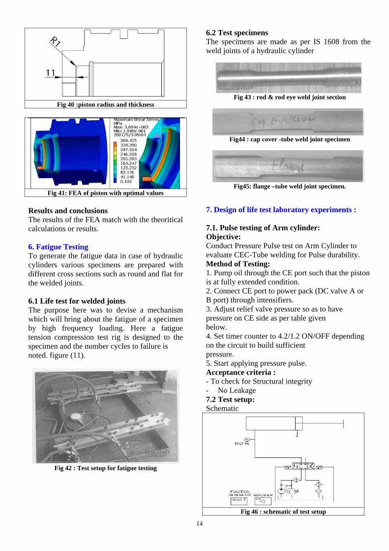
Fig 40 :piston radius and thickness
Fig 41: FEA of piston with optimal values
Results and conclusionsThe results of the FEA match with the theoriticalcalculations or results.
6. Fatigue TestingTo generate the fatigue data in case of hydrauliccylinders various specimens are prepared withdifferent cross sections such as round and flat forthe welded joints.
6.1 Life test for welded jointsThe purpose here was to devise a mechanismwhich will bring about the fatigue of a specimenby high frequency loading. Here a fatiguetension compression test rig is designed to thespecimen and the number cycles to failure isnoted. figure (11).
Fig 42 : Test setup for fatigue testing
6.2 Test specimensThe specimens are made as per IS 1608 from theweld joints of a hydraulic cylinder
Fig 43 : rod & rod eye weld joint section
Fig44 : cap cover -tube weld joint specimen
Fig45: flange –tube weld joint specimen.
7. Design of life test laboratory experiments :
7.1. Pulse testing of Arm cylinder:Objective:Conduct Pressure Pulse test on Arm Cylinder toevaluate CEC-Tube welding for Pulse durability.Method of Testing:1. Pump oil through the CE port such that the pistonis at fully extended condition.2. Connect CE port to power pack (DC valve A orB port) through intensifiers.3. Adjust relief valve pressure so as to havepressure on CE side as per table givenbelow.4. Set timer counter to 4.2/1.2 ON/OFF dependingon the circuit to build sufficientpressure.5. Start applying pressure pulse.Acceptance criteria :- To check for Structural integrity- No Leakage7.2 Test setup:Schematic
Fig 46 : schematic of test setup

15
Test detailsAbove cylinder with new tube wherein OD isincreased from 131 to 135 and CEC TubeSemi-Weld angle 7.5 degrees was subjected topressure pulse test as above. No external leakagewas observed during the test. After the test thecylinder was subjected to internal leakage test @50, 100, 150,200, 250, 300, 350 bar using handpump for 3 min by pressurizing the CE port&pouring oil on other side of cylinder &observing for any oil seepage through theother HE port. Test was repeated for HE side.No internal leakage was observed.
Dismantled cylinder
Fig 47: tube rod subassy with tube
Fig 48: tube with oring subassy
The above figures show the dismantledhydraulic cylinder with tube rod subassemblyand tube. After the test the cylinder wassubjected to internal leakage test at differentpressures using hand pump by pressurizing theCE port & pouring oil on other side of cylinder& observing for any oil seepage through theother HE port. Test was repeated for HE side.No internal leakage was observed.
7.3. Conclusion:- No external leakage found.- No internal leakage observed.Hence the above cylinder has passed the testsuccessfully.
8. Test setupsThe below are the test lab facilities available at oursite.
Bell crank setup to test the hydraulic cylinderunder shock loads.
Fig 49 : Bell crank setup
Tilt test bench to simulate the fork lift tiltfunction.
Fig 50 : Tilt test bench
Hydrostatic simulation of steering cylinder.
Fig 51 : steering test bench

16
Pulse pressure durability on cylinder joints andtubes by generating sudden pressure spikes
Fig 52 : spike or pulse generation test
Stroke durability through pressure cycling
Fig 53 : Back to back testing
Hot oil chamber with high critical workconditions
Fig 55: High temperature pressure spike
9. Summary
A systematic approach to study the differenttypes of Joints and their pains in a hydrauliccylinder are presented here. The study covereddetailed Joint construction, material, design,static and dynamic loading aspects of differentjoints.
We covered the basic working principle alongwith applications, basic functional aspects andcyclic - dynamic loading of joints of hydrauliccylinder. The force flow at different workingstages in double acting and telescopic cylindersare described for better understanding of stressflow pattern.
The stress and life estimation of the joints aredescribed with different case studies. The stressestimation case studies involved, Cap cover tubeweld joint analysis, Piston rod radius optimization,Piston critical section analysis, Tube-head endcover flare off etc.,.
The paper involved two lab testing simulationsnamely Fatigue testing of weld joints and Pulsetesting of Arm cylinder, All these tests areconducted after proving the design theoretically.
The different test setups developed in-house aredescribed in the last section for lab simulation ofdifferent types of Hydraulic cylinder.
All these systematic approaches enhanced the life ofhydraulic cylinders and hence to an end equipment.
10. References
1. Andrew D. Dimarogonas, "Computer aided
machine design", Prentice Hall International,
Ltd. United states.
2. ASM Handbook on Fatigue and Fracture
Volume 19.
3. M F Spotts and T E Shoup, Design of Machine
Elements, Seventh Edition.
4. Wipro Company standards.
5. Paul M. Kurowski, Finite Element Analysis for
Design Engineers, SAE Publications.
6. Howard E. Boyer, Atlas of Fatigue curves,
ASM International, The materials information
Society.