Joint Specifications, Guide and Bit Selection FMT User Guide App1...JOINT SPECIFICATIONS, GUIDE AND...
14
SUPER FMT Appendix I 45 Joint Specifications, Guide and Bit Selection A1-1 Joint Terminology The tenon sides are the “Cheeks” ➀ . The tenon shoulders are called (luckily) the “Shoulders” ➁ . Unfortunately, references to dimensions of mortises and tenons do not share matching terminology, so... Long or short tenons ➂ fit into deep or shallow mortises ➃ . Tenon Length = Mortise Depth. 1 2 3 4 A1-2 Wide or narrow tenons ➄ fit into long or short mortises ➅ . Tenon Width = Mortise Length. 6 5 A1-3 Thick or thin tenons ➆ fit into wide or narrow mortises ➇ . Tenon Thickness = Mortise Width. 7 8 A1-4 Largest Single Rail and Tenon (using one table position with 1 ⁄ 4" bit) Workpiece 1 5 ⁄ 16" x 3 1 ⁄ 8"[34 x 80mm] ➀ . Tenon 1 ⁄ 2" x 2 1 ⁄ 2"[12 x 65mm] ➁ . Guide 1 ⁄ 2" x 2 1 ⁄ 2"[12 x 65mm]. Note: To rout single tenons in stock thicker than 1 5 ⁄ 16"[34mm] would require the bit to be plunged into the edge of the workpiece, “trap- ping” the bit. That could be dangerous, so follow the “Third Tenon” procedure from instruction 4-77 through 4-82. 1 2 1 2 Foreword The illustrations and specifications in this Appendix show the largest tenon rail and tenon sizes possible on the Super FMT, either in one table position or multiple table positions as noted. For all smaller sizes, refer to the guide and bit selection chart. Joint Specifications
Transcript of Joint Specifications, Guide and Bit Selection FMT User Guide App1...JOINT SPECIFICATIONS, GUIDE AND...

JOINT SPECIFICATIONS, GUIDE AND bIT SELECTION
Super FMT Appendix I
45
Joint Specifications,Guide and Bit Selection
A1-1 Joint Terminology The tenon sides are the “Cheeks” ➀. The tenon shoulders are called (luckily) the “Shoulders” ➁.Unfortunately, references to dimensions of mortises and tenons do not share matching terminology, so...Long or short tenons ➂ fit into deep or shallow mortises ➃.Tenon Length = Mortise Depth.
1
2
3
4
A1-2 Wide or narrow tenons ➄ fit into long or short mortises ➅.Tenon Width = Mortise Length.
6
5
A1-3 Thick or thin tenons ➆ fit into wide or narrow mortises ➇. Tenon Thickness = Mortise Width.
7
8
A1-4 Largest Single Rail and Tenon(using one table position with 1⁄4" bit)Workpiece 1 5⁄16" x 31⁄8"[34 x 80mm] ➀.Tenon 1⁄2" x 21⁄2"[12 x 65mm] ➁.Guide 1⁄2" x 21⁄2"[12 x 65mm].Note: To rout single tenons in stock thicker than 15⁄16"[34mm] would require the bit to be plunged into the edge of the workpiece, “trap-ping” the bit. That could be dangerous, so follow the “Third Tenon” procedure from instruction 4-77 through 4-82.
1
2
1 2
ForewordThe illustrations and specifications in this Appendix show the largest tenon rail and tenon sizes possible on the Super FMT, either in one table position or multiple table positions as noted. For all smaller sizes, refer to the guide and bit selection chart.
Joint Specifications
46 Appendix I Super FMT Frame Mortise & Tenon Jig User Guide JOINT SPECIFICATIONS, GUIDE AND bIT SELECTION
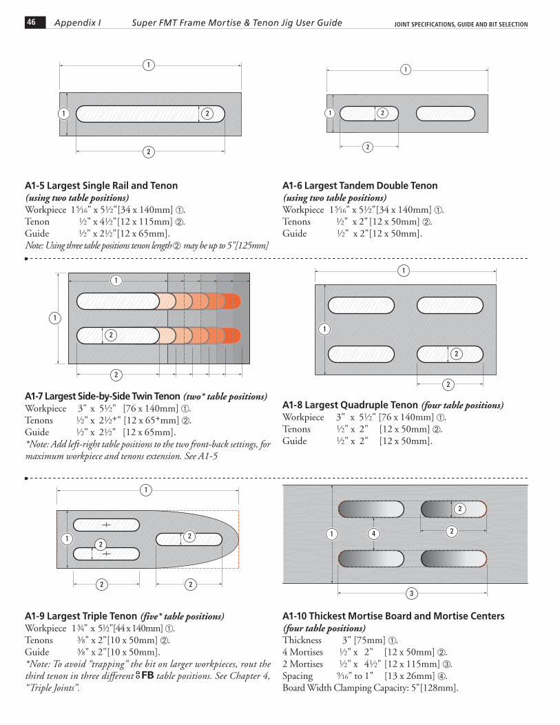
A1-10 Thickest Mortise Board and Mortise Centers(four table positions)Thickness 3" [75mm] ➀.4 Mortises 1⁄2" x 2" [12 x 50mm] ➁.2 Mortises 1⁄2" x 41⁄2" [12 x 115mm] ➂.Spacing 9⁄16" to 1" [13 x 26mm] ➃.Board Width Clamping Capacity: 5"[128mm].
2
3
1
2
4
A1-5 Largest Single Rail and Tenon(using two table positions) Workpiece 1 5⁄16" x 51⁄2"[34 x 140mm] ➀.Tenon 1⁄2" x 41⁄2"[12 x 115mm] ➁.Guide 1⁄2" x 21⁄2"[12 x 65mm].Note: Using three table positions tenon length ➁ may be up to 5"[125mm]
1
2
1 2
A1-6 Largest Tandem Double Tenon (using two table positions)Workpiece 1 5⁄16" x 51⁄2"[34 x 140mm] ➀.Tenons 1⁄2" x 2" [12 x 50mm] ➁.Guide 1⁄2" x 2"[12 x 50mm].
1
2
1 2
A1-7 Largest Side-by-Side Twin Tenon (two* table positions)
Workpiece 3" x 51⁄2" [76 x 140mm] ➀.Tenons 1⁄2" x 21⁄2+" [12 x 65+mm] ➁.Guide 1⁄2" x 21⁄2" [12 x 65mm].*Note: Add left-right table positions to the two front-back settings, for maximum workpiece and tenons extension. See A1-5
1
2
1
2
A1-8 Largest Quadruple Tenon (four table positions)
Workpiece 3" x 51⁄2" [76 x 140mm] ➀.Tenons 1⁄2" x 2" [12 x 50mm] ➁.Guide 1⁄2" x 2" [12 x 50mm].
1
2
1
2
A1-9 Largest Triple Tenon (five* table positions)
Workpiece 1 3⁄4" x 51⁄2"[44 x 140mm] ➀.Tenons 3⁄8" x 2"[10 x 50mm] ➁.Guide 3⁄8" x 2"[10 x 50mm].*Note: To avoid “trapping” the bit on larger workpieces, rout the third tenon in three different FB table positions. See Chapter 4, “Triple Joints”.
1
22
1 22

47Appendix IJOINT SPECIFICATIONS, GUIDE AND bIT SELECTION Super FMT Frame Mortise & Tenon Jig User Guide
A1-11 Widest, Deepest Workpieces for Mortising to CenterWidth up to 45⁄8"[115mm] ➀.Depth up to 4" [100mm] ➁.Note: See 4-105 mounting instructions for these pieces.
2
1
A1-12 Maximum-width Board for Mortising to CenterWidth from 45⁄8" [115mm] up to 61⁄2"[165mm] ➀See special instructions 4-106. ■
Guide and Bit Selection
1
Guide and Bit SelectionUse the charts on the next few pages to select appropriate guide and bit combinations. ➔

48 Appendix I
LEIGH BIT ITEM NO. A B B C
HSS Solid Carbide Mortise Size HSS Solid Carbide Shank Spiral Upcut Spiral Upcut Cutting Diameter Cutting Depth Cutting Depth Diameter
162 N/A 1/16" 3/16" - 1/4" 164 164C 1/8" 3/8" 1/2" 1/4" 166 166C 3/16" 5/8" 3/4" 1/4" 168 168C 1/4" 1" 1-1/8" 1/4" 170-500 170-500C 5/16" 1" 1-1/8" 1/2" 173-500 173-500C 3/8" 1-1/4" 1-1/4" 1/2" 177 177C 7/16" 1-3/4" 1-3/4" 1/2" 180 180CL 1/2" 1-1/2" 2-1/8" 1/2"
BIT SPECIFICATIONS
Note: For metric bit specifications, please see your national Leigh distributor.
Super FMT Frame Mortise & Tenon Jig User Guide JOINT SPECIFICATIONS, GUIDE AND bIT SELECTION
Note: Joints routed with a single bit are shown shaded.
In addition to the joint sizes listed in the charts, any tenon width (mortise length) can easily be achieved by using the jig’s quick-acting table movement and limit stops as described in Chapter 4, Longer or Shorter Joints. By using combinations of machine tool bits, even more sizes of small and miniature joints may be routed. See Chapter 4, Small Joints.
INCH GUIDE AND BIT SELECTION CHART
MORTISEBIT
MORTISEBIT
JOINTSIZE
JOINTSIZE
GUIDESIZE
GUIDESIZE
TENONBIT
TENONBIT
1/16" x 1/8"
1/16" x 3/16"
1/16" x 5/16"
1/16" x 7/16"
1/16" x 9/16"
1/16" x 13/16"
1/16" x 1-1/16"
1/16" x 1-5/16"
1/8" x 3/16"
1/8" x 1/4"
1/8" x 5/16"
1/8" x 3/8"
1/8" x 1/2"
1/8" x 9/16"
1/8" x 5/8"
1/8" x 13/16"
1/8" x 7/8"
1/8" x 1-1/16"
1/8" x 1-1/8"
1/8" x 1-5/16"
1/8" x 1-3/8"
3/16" x 1/4"
3/16" x 5/16"
3/16" x 3/8"
3/16" x 7/16"
3/16" x 9/16"
3/16" x 5/8"
3/16" x 11/16"
3/16" x 7/8"
3/16" x 15/16"
3/16" x 1-1/8"
3/16" x 1-3/16"
3/16" x 1-3/8"
3/16" x 1-7/16"
1/16
1/16
1/16
1/16
1/16
1/16
1/16
1/16
1/8
1/8
1/8
1/8
1/8
1/8
1/8
1/8
1/8
1/8
1/8
1/8
1/8
3/16
3/16
3/16
3/16
3/16
3/16
3/16
3/16
3/16
3/16
3/16
3/16
3/16
7/16
7/16
7/16
7/16
7/16
7/16
7/16
7/16
3/8
3/8
1/2
3/8
3/8
1/2
3/8
1/2
3/8
1/2
3/8
1/2
3/8
5/16
5/16
7/16
5/16
5/16
7/16
5/16
7/16
5/16
7/16
5/16
7/16
5/16
1/4" x 5/16"
1/4" x 3/8"
1/4" x 1/2"
1/4" x 5/8"
1/4" x 3/4"
1/4" x 1"
1/4" x 1-1/4"
1/4" x 1-1/2"
1/4" x 5/16"
1/4" x 3/8"
5/16" x 1/2"
1/4" x 1/2"
1/4" x 5/8"
5/16" x 3/4"
1/4" x 3/4"
5/16" x 1"
1/4" x 1"
5/16" x 1-1/4"
1/4" x 1-1/4"
5/16" x 1-1/2"
1/4" x 1-1/2"
1/4" x 5/16"
1/4" x 3/8"
5/16" x 1/2"
1/4" x 1/2"
1/4" x 5/8"
5/16" x 3/4"
1/4" x 3/4"
5/16" x 1"
1/4" x 1"
5/16" x 1-1/4"
1/4" x 1-1/4"
5/16" x 1-1/2"
1/4" x 1-1/2"
1/4" x 5/16"
1/4" x 3/8"
1/4" x 7/16"
1/4" x 1/2"
1/4" x 5/8"
1/4" x 11/16"
1/4" x 3/4"
1/4" x 15/16"
1/4" x 1"
1/4" x 1-3/16"
1/4" x 1-1/4"
1/4" x 1-3/8"
1/4" x 1-7/16"
1/4" x 1-1/2"
1/4" x 1-7/8"
1/4" x 2-3/8"
5/16" x 1/2"
5/16" x 3/4"
5/16" x 15/16"
5/16" x 1"
5/16" x 1-1/4"
5/16" x 1-7/16"
5/16" x 1-1/2"
5/16" x 1-15/16"
5/16" x 2-7/16"
3/8" x 1"
3/8" x 1-1/2"
3/8" x 2"
3/8" x 2-1/2"
1/2" x 1"
1/2" x 1-1/2"
1/2" x 2"
1/2" x 2-1/2"
1/4
1/4
1/4
1/4
1/4
1/4
1/4
1/4
1/4
1/4
1/4
1/4
1/4
1/4
1/4
1/4
5/16
5/16
5/16
5/16
5/16
5/16
5/16
5/16
5/16
3/8
3/8
3/8
3/8
1/2
1/2
1/2
1/2
1/4
1/4
3/8
1/4
1/4
3/8
1/4
3/8
1/4
3/8
1/4
1/2
3/8
1/4
1/2
1/2
5/16
5/16
7/16
5/16
5/16
7/16
5/16
7/16
7/16
3/8
3/8
3/8
3/8
1/2
1/2
1/2
1/2
1/4" x 5/16"
1/4" x 3/8"
5/16" x 1/2"
1/4" x 1/2"
1/4" x 5/8"
5/16" x 3/4"
1/4" x 3/4"
5/16" x 1"
1/4" x 1"
5/16" x 1-1/4"
1/4" x 1-1/4"
3/8" x 1-1/2"
5/16" x 1-1/2"
1/4" x 1-1/2"
3/8" x 2"
3/8" x 2-1/2"
5/16" x 1/2"
5/16" x 3/4"
3/8" x 1"
5/16" x 1"
5/16" x 1-1/4"
3/8" x 1-1/2"
5/16" x 1-1/2"
3/8" x 2"
3/8" x 2-1/2"
3/8" x 1"
3/8" x 1/2"
3/8" x 2"
3/8" x 2-1/2"
1/2" x 1"
1/2" x 1-1/2"
1/2" x 2"
1/2" x 2-1/2"

49Appendix ISuper FMT Frame Mortise & Tenon Jig User GuideJOINT SPECIFICATIONS, GUIDE AND bIT SELECTION
METRIC GUIDE AND BIT SELECTION CHART
6
6
6
6
6
6
6
6
6
6
6
6
6
6
7
7
7
7
7
7
8
8
8
8
8
8
8
8
8
8
8
10
10
10
10
10
12
12
12
12
12
2 x 4
2 x 6
2 x 11
2 x 16
2 x 21
2 x 26
2 x 31
2 x 36
3 x 5
3 x 7
3 x 12
3 x 17
3 x 22
3 x 27
3 x 32
3 x 37
4 x 6
4 x 8
4 x 11
4 x 13
4 x 16
4 x 18
4 x 21
4 x 23
4 x 26
4 x 28
4 x 31
4 x 33
4 x 36
4 x 38
5 x 7
5 x 9
5 x 14
5 x 19
5 x 24
5 x 29
5 x 34
5 x 39
2
2
2
2
2
2
2
2
3
3
3
3
3
3
3
3
4
4
4
4
4
4
4
4
4
4
4
4
4
4
5
5
5
5
5
5
5
5
10
10
10
10
10
10
10
10
9
9
9
9
9
9
9
9
8
8
12
8
12
8
12
8
12
8
12
8
12
8
7
7
7
7
7
7
7
7
6 x 8
6 x 10
6 x 15
6 x 20
6 x 25
6 x 30
6 x 35
6 x 40
6 x 8
6 x 10
6 x 15
6 x 20
6 x 25
6 x 30
6 x 35
6 x 40
6 x 8
6 x 10
8 x 15
6 x 15
8 x 20
6 x 20
8 x 25
6 x 25
8 x 30
6 x 30
8 x 35
6 x 35
8 x 40
6 x 40
6 x 8
6 x 10
6 x 15
6 x 20
6 x 25
6 x 30
6 x 35
6 x 40
6 x 8
6 x 10
6 x 13
6 x 15
6 x 18
6 x 20
6 x 23
6 x 25
6 x 28
6 x 30
6 x 33
6 x 35
6 x 38
6 x 40
7 x 14
7 x 19
7 x 24
7 x 29
7 x 34
7 x 39
8 x 15
8 x 20
8 x 23
8 x 25
8 x 30
8 x 33
8 x 35
8 x 40
8 x 43
8 x 53
8 x 63
10 x 25
10 x 35
10 x 45
10 x 55
10 x 65
12 x 25
12 x 35
12 x 45
12 x 55
12 x 65
6
6
10
6
10
6
10
6
10
6
10
6
10
6
9
9
9
9
9
9
8
8
12
8
8
12
8
8
12
12
12
10
10
10
10
10
12
12
12
12
12
6 x 8
6 x 10
8 x 15
6 x 15
8 x 20
6 x 20
8 x 25
6 x 25
8 x 30
6 x 30
8 x 35
6 x 35
8 x 40
6 x 40
8 x 15
8 x 20
8 x 25
8 x 30
8 x 35
8 x 40
8 x 15
8 x 20
10 x 25
8 x 25
8 x 30
10 x 35
8 x 35
8 x 40
10 x 45
10 x 55
10 x 65
10 x 25
10 x 35
10 x 45
10 x 55
10 x 65
12 x 25
12 x 35
12 x 45
12 x 55
12 x 65
GUIDESIZE
GUIDESIZE
JOINTSIZE
TENONBIT
TENONBIT
MORTISEBIT
MORTISEBIT
JOINTSIZE

50 Appendix I Super FMT Frame Mortise & Tenon Jig User Guide JOINT SPECIFICATIONS, GUIDE AND bIT SELECTION

JIG ADJUSTMENTS
Super FMT Appendix II
51
Jig Adjustments
A2-1 Clamp Plate The clamp plate is factory set square to the table ➀. However, this does not guarantee perfectly in-line joints. If your router shaft and bit are not perpendicular to the router sub-base and the Leigh sub-base, then the bit will not be square to the jig table (nor parallel to the clamp plate). This will cause a tiny “step” in the joint alignment ➁. This is because the tenon center mark is now offset from the mortise center mark in the assembled joint ➂. For clarity, the angle and step in this example is highly exaggerated.
90˚
2
3
2
1
A2-2 Check your test joints for alignment with a straightedge. The cross represents the inside face toward the clamp face. The left example shows the clamp plate should be adjusted in toward the jig body ➀. The right example shows the clamp plate should be adjusted away from the jig body ➁. Test and adjust the clamp plate angle (see below) until the workpieces are in the same plane, with no joint misalignment.
1 2
A2-3 The adjusting screw for setting the clamp plate is in the lower left front of the jig base. Loosen the quadrant knobs. Use the hex screwdriver to turn the screw clockwise to move the plate in ➀. Turn the screw counterclockwise to move the plate out ➁. The screw is treated with Loctite™ to prevent accidental rotation and will require firm pressure to adjust.
12
A2-4 Joint Alignment The clamp plate is factory set parallel to the guide track centerline and should not need attention. If the mortise or tenon is angled ➀ an adjustment may be required. Here’s how: Slightly loosen the two screws ➀ holding the left end quadrant using the hex driver. Turn the screw in or out ➁ to adjust the angle of the clamp plate relative to the guide track centerline. Firmly tighten the screws. After tightening the two screws, turn the adjusting screw in towards the jig body at least two full turns. Rout test joints to check the joint alignment.
2
1
1

52 Appendix II JIG ADJUSTMENTSSuper FMT Frame Mortise & Tenon Jig User Guide
A2-5 Sidestop Squareness The travel of the router bit must be perfectly parallel to the sidestop fence. The sidestop fence is factory set square to the bottom of the jig table, however, tolerances in plunge routers may necessitate a small sidestop adjustment. If adjustment is required, the set screw on the bottom right side of the sidestop fence ➀ is turned in or out to change the angle of the fence. ■
90˚
1 11

CUSTOMER SUPPORT
Super FMT Appendix III
53
Super FMT Parts List

54 Appendix III Super FMT Frame Mortise & Tenon Jig User Guide CUSTOMER SUPPORT
Main CoMponents9000 1 Jig Frame 9010 1 Clamp Plate 9020 1 Table Plate 9030 1 LH Clamp Plate Pivot 9040 1 RH Clamp Plate Pivot 9050 2 Clamp Plate Struts 9060 1 Intermediate Plate 9070 1 Sub-base sub-base CoMponents 5100 2 Router Hold-down Rods 9100 4 Router Rod Clamps 9110 4 Router Rod Clamp Knobs, Brass 9120 4 Router Rod Clamp Screws 10-24 x 1-3/4" 6410 4 Router Rod Clamp Screws 10-24 x 3/8" 9140 4 Sliding Washer/Limit Stop Nuts 9150 4 Router Clamp Sliding Washers 9160 2 Brass Guide Pins 9170 2 Brass Guide Pin Lock Nuts 9180 1 Sub-base Knob table anD interMeDiate plate
CoMponents 3090 2 Carriage Bolts 1/4-20 x 3/4" 5300 1 Sight Magnet 6030 2 Table /Pivot Knob, Vac Box Nuts6199 4 Limit Stop Washers9140 4 Sliding Washer/Limit Stop Nuts 9200 2 Table/Pivot Lock Knobs 9210 2 Nylon Washers (not shown) 9220 1 Guide Base 9230 1 Guide Base Latch 9240 1 Guide Pin Track 9250 1 Sight 9260 2 Limit Stop Tracks 9270 4 Limit Stop Screws 9280 4 Limit Stop Track Hold-down Screws 9280 12 Guide Base, Guide Pin Track Hold-down Screws (n/s)9300 1 UHMW Table Plate Strip 6-3/4" x 1/4" (not shown) 9310 2 UMHW Intermediate Plate Strips (not shown)9320 2 Ring Magnets
Main FraMe CoMponents 6030 2 Table /Pivot Knob, Vac Box Nuts 6199 4 Flat Washers 6410 4 Button Head Cap Screws 10-24 x 3/8" 9130 2 Clamp Plate Angle Adjustment Screws 9200 2 Table/Pivot Lock Knobs 9320 2 Ring Magnets (not shown) 9410 2 Carriage Bolts 1/4-20 x 1/2" (not shown)
Part Quantity Partno. Per Jig DescriPtion
Part Quantity Partno. Per Jig DescriPtion
ClaMp plate CoMponents 6026 1 Sidestop Fender Washer 6199 4 Flat Washers9080 1 Sidestop Fence9500 2 F-Clamps, complete with Magnets and Pads 9510 2 F-Clamp Back Pads (not shown) 9520 2 F-Clamp Back Pad Magnets (not shown) 9530 1 Sidestop Lever6125 1 Sidestop Set Screw 1/4-28 9550 1 Sidestop Carriage Bolt 1/4-20 x 5/8" (not shown) 9560 4 Button Head Cap Screws 10-24 x 1/2" other CoMponents 170-500 1 5/16" HSS Spiral Upcut Bit5130 2 M6 Screws for Festool OF1400 and OF2200 6905 1 1/8" Hex Driver 6030 4 Jig Hold-down Nuts 6060 4 Jig Hold-down Screws 6410 3 Screws for Porter Cable Router 6665 1 Imperial Router Centering Mandrel 1/4" x 1/2" 6670 1 Metric Router Centering Mandrel 8mm x 12mm 6700 1 Template Guide Stand 6705 1 5/16" Template Guide Set (inch Jig only) 670508 1 5/16" x 1/2" Template Guide 670512 1 5/16" x 3/4" Template Guide 670516 1 5/16" x 1" Template Guide 670520 1 5/16" x 1-1/4" Template Guide 670524 1 5/16" x 1-1/2" Template Guide6808 1 8mm Template Guide Set (Metric Jig only) 680815 1 8 mm x 15 mm Template Guide 680820 1 8 mm x 20 mm Template Guide 680825 1 8 mm x 25 mm Template Guide 680830 1 8 mm x 30 mm Template Guide 680835 1 8 mm x 35 mm Template Guide 680840 1 8 mm x 40 mm Template Guide9600 1 User Guide 1 Serial Number Decal (not shown)
optional CoMponents VBSMT 1 Vacuum Box Attachment 5040 1 Small Hose Adaptor 5345 1 Large Hose Adaptor 6030 2 Table /Pivot Knob, Vac Box Nuts 9700 1 Vac Box 9710 1 Vac Box Nozzle

55Appendix IIICUSTOMER SUPPORT Super FMT Frame Mortise & Tenon Jig User Guide
6700
6905
670508670512670516670520
670524
Note: See Parts List for metric guides.
Optional Vacuum Attachment
6670
9070
5130
6410
9230
9060
9000
9130
920094106030
9030 LH9040 RH
9050
64106199
9600
5300
9130
9560
9180
9200309060309210
170-500
9260
9520
6030
9510
9010
924090209220
9250
9000
5100
9110
9010
9560
6665
9500
90806125
VBSMT
95306026
9700
5345
9710
5040
9320
9100
912091409150
927061999140
91609170
9260
9280
60306060
9280

56 Appendix III Super FMT Frame Mortise & Tenon Jig User Guide CUSTOMER SUPPORT

CUSTOMER SUPPORT
Super FMT Appendix IV
Customer Support
At Leigh Industries we take pride in our commitment to provide excellence in customer service and support. We hope your use of the Leigh Super FMT is enjoyable, rewarding and most of all, trouble free. This user guide should provide you with the answers to any questions you may have. If this is not the case, please feel free to contact our technical support staff or our distributor in your country by any of the means listed below.
Leigh Industries Ltd. (EST. 1981)P.O. Box 357,1615 Industrial Ave.,Port Coquitlam, B.C.,Canada, V3C 4K6
Toll Free: 800-663-8932 Tel: (604) 464-2700 Fax: (604) 464-7404*Email: [email protected] Web: www.leighjigs.com
* Email can be useful, but technical queries usually raise queries from us. The telephone (if possible) is a much quicker and more convenient way to get those queries answered; either directly to Leigh (toll free in North America) or to your national distributor.
…Thanks!
Manufacturer: Canada & USA
Australia & New ZealandCarba-Tec Pty. Ltd.40 Harries Rd, Coorparoo, Qld., 4151Tel: (07) 3397 2577Fax: (07) 3397 2785Order: 1 800 658 111Email: [email protected]
FranceEts Bordet23 Rue Traversiere93556 Montreuil CedexFranceTel: 01 48 58 28 39Fax: 01 48 58 48 58Email: [email protected]: www.bordet.fr/
Germany, Austria & SwitzerlandHacker GMBHHolzbearbeitungsmaschinenTraberhofstraße 103 D-83026 RosenheimDeutschlandTel: 08031 269650Fax: 08031 68221Email: [email protected]: www.leigh.de
JapanOff Corporation Inc.323-1 Shimizu-Yanbara Shimizu-KuShizuoka-Shi, Shizuoka-Ken,Japan 424-0002Tel: 81-54-367-6511Fax: 81-54-367-6515Email: [email protected]: www.off.co.jp
KoreaLeigh Korea1st Floor, Yongyu Building 25-3Neung Pyung-Ri, Opo-Eup, Kwangju-SiKyunggi-do, KoreaTel: 82 (0) 70-8252-0988Fax: 82 (0) 31-765-5602Email: [email protected]: www.woodworking-academy.com
NorwayAurusStoelsmyrvn. 1035542 KarmsundNorwayTel: +47 992 71 932Fax: +47 529 10 011Email: [email protected]: www.aurus.no
RussiaUnicom Ltd.Nikitskij Boulevard 12Moscow, 119019RussiaTel/Fax: +7(495)690-0454Email: [email protected] (Russia)Email: [email protected] (Ukraine)Web: www.leighjigs.ru (Russia)Web: www.leighjigs.ua (Ukraine)
South AfricaHardware Centre GroupPO Box 4059, 2125Randburg, South AfricaTel: (011) 791-0844/46Fax: (011) 791-0850Email: [email protected]: www. hardwarecentre.co.za
SwedenToolbox Sweden ABFacetten Faj 9S-597 30 AtvidabergSwedenTel: 46-120-854-50Fax: 46-120-854-69Email: [email protected]: www.toolbox.se
United Kingdom & IrelandBriMarc Tools & MachineryUnit 10a Weycroft AvenueAxminsterDevon EX13 5PHEnglandTel: 0300 100 1008Fax: 0300 100 1009Email: [email protected]: www.brimarc.com
Distributors
Our Commitment to You
57

© 2009 Leigh Industries Ltd. All rights reserved.No part of this publication may be reproduced, stored in a retrieval system, or transmitted in any form or by any means, electronic, mechanical, recording, or otherwise, without the prior written permission of Leigh Industries Ltd. 09/09
Printed in Canada
LEIGH INDUSTRIES LTD.Manufacturers of Precision
Woodworking Tools
PO Box 357(1615 Industrial Ave.)Port Coquitlam, BCCanada V3C 4K6


![Competing Transformations[Prnt Fmt]](https://static.fdocuments.us/doc/165x107/5400655bdab5caaf758b46eb/competing-transformationsprnt-fmt.jpg)