Joint PHY-MAC Designs and Smart Antennas for Wireless Ad-Hoc Networks CS 838 - Mobile and Wireless...
32
Joint PHY-MAC Designs and Smart Antennas for Wireless Ad-Hoc Networks CS 838 - Mobile and Wireless Networking (Fall 2006)
-
Upload
allyson-merryl-booker -
Category
Documents
-
view
213 -
download
0
Transcript of Joint PHY-MAC Designs and Smart Antennas for Wireless Ad-Hoc Networks CS 838 - Mobile and Wireless...

Joint PHY-MAC Designs and Smart Antennas for Wireless Ad-Hoc Networks
CS 838 - Mobile and Wireless Networking
(Fall 2006)
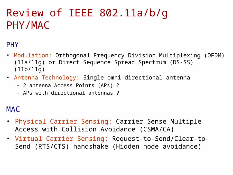
Review of IEEE 802.11a/b/g PHY/MAC
PHY• Modulation: Orthogonal Frequency Division Multiplexing (OFDM)
(11a/11g) or Direct Sequence Spread Spectrum (DS-SS) (11b/11g)• Antenna Technology: Single omni-directional antenna
– 2 antenna Access Points (APs) ?– APs with directional antennas ?
MAC• Physical Carrier Sensing: Carrier Sense Multiple Access with
Collision Avoidance (CSMA/CA)• Virtual Carrier Sensing: Request-to-Send/Clear-to-Send
(RTS/CTS) handshake (Hidden node avoidance)
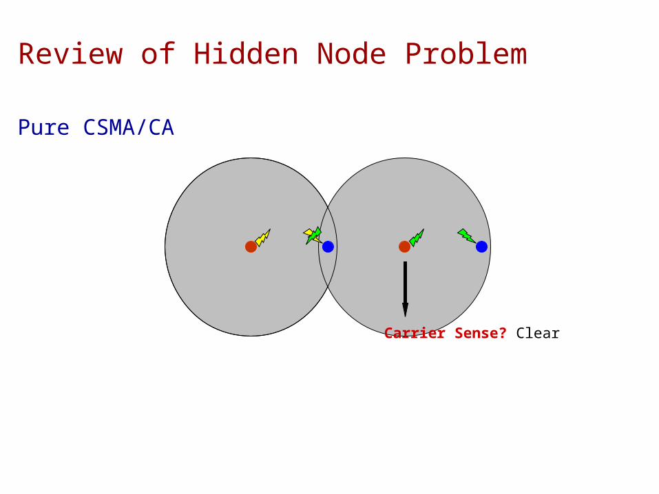
Review of Hidden Node Problem
Pure CSMA/CA
Carrier Sense? Clear

802.11 Solution of Hidden Node Problem
CSMA/CA with RTS/CTS
Virtual Carrier Sense? Busy
RTS CTS
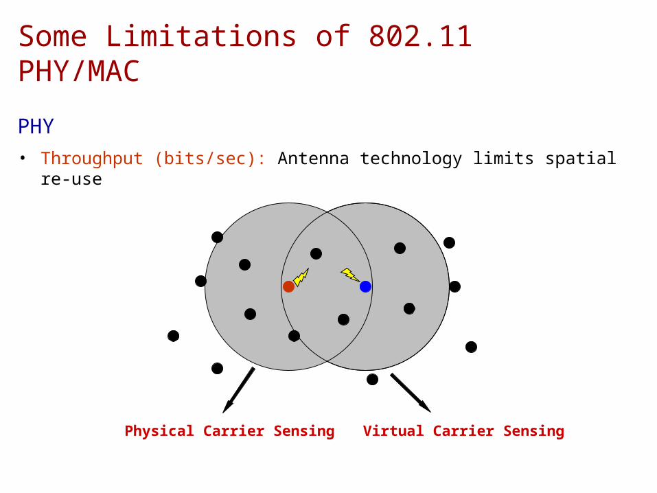
Some Limitations of 802.11 PHY/MAC
PHY• Throughput (bits/sec): Antenna technology limits spatial re-use
Physical Carrier Sensing Virtual Carrier Sensing

MAC• Throughput: RTS/CTS handshake further limits the spatial re-
use in the network • Fairness (and Throughput): RTS/CTS fails to completely take
care of the hidden node problem, resulting in dropped packets for one transmission more than the other– Interference range is typically more than the successful reception
range of CTS
• Fairness: 802.11 MAC can unfairly favor one transmission over the other as a function of the distance between the nodes
Some Limitations of 802.11 PHY/MAC (contd.)
CTSX

802.11 Simulated Performance [TPHN04]
Linear Topology: 0 1 2 3200 m 200 mD
Hidden node effectThroughput reduction
(and unfairness) due to spatial proximity

[TPHN04] Proposed Solution
PHY• Single transmit/multiple receive antennas with OFDM modulation
MAC• Mitigating Interference using Multiple Antennas MAC (MIMA-MAC)
– Built on top of 802.11 MAC with antenna awareness– N nodes in spatial proximity would be allowed to transmit
simultaneously in a network of nodes with N receive antennas– PHY expected to cancel the interference of (N-1) unintended
flows using advanced signal processing techniques
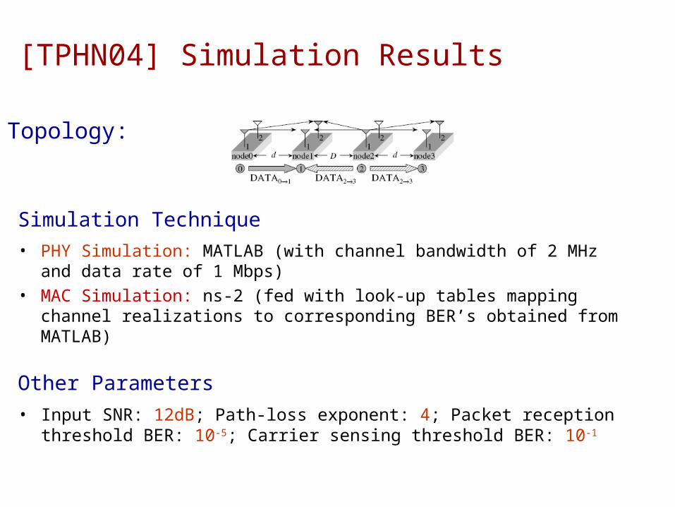
[TPHN04] Simulation Results
Simulation Technique• PHY Simulation: MATLAB (with channel bandwidth of 2 MHz and
data rate of 1 Mbps)• MAC Simulation: ns-2 (fed with look-up tables mapping channel
realizations to corresponding BER’s obtained from MATLAB)
Topology:
Other Parameters• Input SNR: 12dB; Path-loss exponent: 4; Packet reception
threshold BER: 10-5; Carrier sensing threshold BER: 10-1
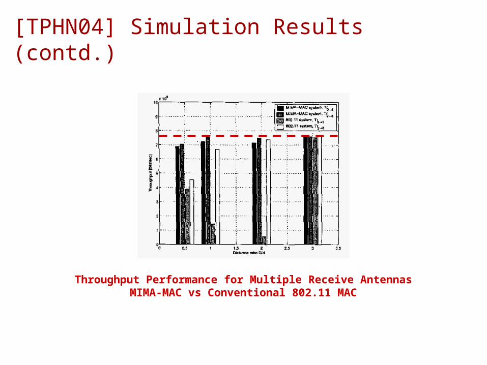
[TPHN04] Simulation Results (contd.)
Throughput Performance for Multiple Receive AntennasMIMA-MAC vs Conventional 802.11 MAC

[TPHN04] Simulation Results (contd.)
Fairness Performance for Multiple Receive AntennasMIMA-MAC vs Conventional 802.11 MAC

Smart Antennas for Wireless Ad-Hoc Networks
Switched Beam Antennas• Pre-determined set of weights applied to
different antenna elements to form a fixed number of high-directionality beams
• A K element array can form up to K beams
• The directionality gain of each beam at the transmitter and the receiver is given by (assuming LOS/low angular spread)
• Assuming that the transmitter and the receiver know each other’s direction, the total transmission gain (SNR gain) is bounded by

Smart Antennas for Wireless Ad-Hoc Networks
Fully Adaptive Arrays• Fully adaptive set of weights applied to
different antenna elements to adaptively change the radiation pattern
• A K element array has K degrees-of-freedom (DOFs), and can adaptively null (K-1) uncorrelated interferers
• Even in the presence of significant multipath scattering, the total transmission gain (SNR gain) of an adaptive array can be given by
• Very high multipath scattering and low signal correlation can some- times limit the gain to

Smart Antennas for Wireless Ad-Hoc Networks
MIMO Links• Digital adaptive arrays capable of operating in
two modes: Spatial Multiplexing and Diversity• A rich set of multipath scattering between the
transmitter and the receiver transforms a K element MIMO link into K independent links
• In multiplexing mode, this can result in K fold increase in the data rate of the MIMO link
• In diversity mode, this can result in a reduction in the variance of the received SNR. At high SNR, this results in

Smart Antennas can be leveraged for …
1) Higher Data Rate• For a given modulation scheme, the bit-error-rate (BER) on a link
is determined by the link SNR• Switched Beam/Adaptive Array: Gain in SNR (G) Perform
adaptive modulation to increase bits transmitted per symbol and keep BER the same
• MIMO Link: Operate the link in the spatial multiplexing mode

Smart Antennas can be leveraged for …
2) Increased Transmission Range• The transmission range of a link is related to the link SNR by
• Switched Beam/Adaptive Array: Gain in SNR (G) Obtain a range extension factor given by
• MIMO Link: Operate the link in the diversity mode. Not a straight forward relationship between the diversity order and the range extension, so resort to MATLAB simulations (diversity mode only reduces SNR variance)

Smart Antennas can be leveraged for …
3) Increased Link Reliability• For a fixed data rate (modulation scheme), the bit-error-rate
(BER) on a link is determined by the link SNR• Switched Beam/Adaptive Array: Gain in SNR (G) For the same
data rata, obtain a reduction in the BER by a factor of
• MIMO Link: Operate the link in the diversity mode. For the same data rate, this can result in a reduction in the BER by a factor of

Smart Antennas can be leveraged for …
4) Reduced Transmit Power• Switched Beam/Adaptive Array: Gain in SNR (G) For the same
BER, obtain a reduction in the transmit power by a factor of
• MIMO Link: Operate the link in the diversity mode. For the same BER, this can result in a reduction in the transmit power given by

[SLS06] Simulation Model
Antenna Model• Switched Beam Array: Pre-determined, fixed beam pattern• Adaptive Array/MIMO Link: Dynamically tunable beam pattern
Channel Model• PHY: BER obtained from MATLAB simulations by assuming a fast
Rayleigh fading collision channel model (per location, antenna technology and strategy), with data rate of 2 Mbps, transmit power of 20 dBm, SINR of 10 dB and fade margin of 0-10 dB
• Link: Packet loss probability obtained from ns-2 (fed with look-up tables of PHY simulations), with packet size of 1000 bytes

[SLS06] Simulation Model (contd.)
Network and Traffic Model• 100 nodes over a rectangular grid of 400x400 m to 1000x1000 m• Number of simultaneous flows in the network varied from 1 to 50• Multipath scattering varied from LOS to 180 degrees (rich scatter)• Number of antenna elements per node varied from 1 to 12• Initial transmission range of each node set to 100 m
Metrics• Throughput (T): Bits per second, normalized by the number of flows• Throughput/Energy (TE): Bits per unit of Joule consumed (consisting
of communication circuit power Pc, transmit power Pt and computational power)

[SLS06] Simulation Model (contd.)
Protocols and Algorithm• Goal: Obtain fundamental tradeoffs in the operation of different
antenna technologies• Requires: Suppressing the inefficiencies of other factors• Solution: Centralized algorithm for finding routes, scheduling
slotted transmissions, ensuring fairness, taking care of interferences etc.
• Routing Strategy: Djikstra’s algorithm
Caveat• Simulation results are not indicative of how things might
perform in a distributed setting

[SLS06] Strategy Comparison: T Metric
Switched Beam Adaptive Array MIMO Links
Setup• High density network, load of 50 flows, fading loss of 5%,
scattering angle of 90 degrees

[SLS06] Strategy Comparison: T Metric (contd.)
Exceptions• Under low node density and small number of flows, range
works better (better connectivity)
4 Antenna elements per node

[SLS06] Strategy Comparison: TE Metric
Switched Beam Adaptive Array MIMO Links
Setup• High density network, load of 50 flows, fading loss of 5%,
scattering angle of 90 degrees and Pt >> Pc
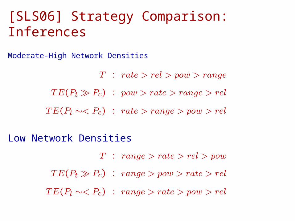
[SLS06] Strategy Comparison: Inferences
Moderate-High Network Densities
Low Network Densities

[SLS06] Antenna Technology Comparison
Parameters of Interest• Network node density• Number of antenna elements• Number of network flows• Scattering angle• Fading loss
Components Impacting T and TE Metrics• Number of independent contention regions density• Number of active links/contention region flows and density• Number of resources/contention region elements and scattering

[SLS06] Technology Comparison: T Metric(Scattering and Elements under Rate Strategy)
Rich Scattering:
Low Scattering:
Rich scattering does not degradeMIMO links’ rate performance

[SLS06] Technology Comparison: T Metric(Scattering and Fading under Rate Strategy)
Fading impacts all rate strategies alike!

[SLS06] Technology Comparison: T Metric(Flows and Elements under Rate Strategy)
No logarithmic effect for MIMO at low load
Low Load:
High Load:

[SLS06] Technology Comparison: T Metric(Flows and Density under Rate/Range Strategy)
Low Load & High Density:
Low Load & Low Density:
Low Load & Moderate Density:
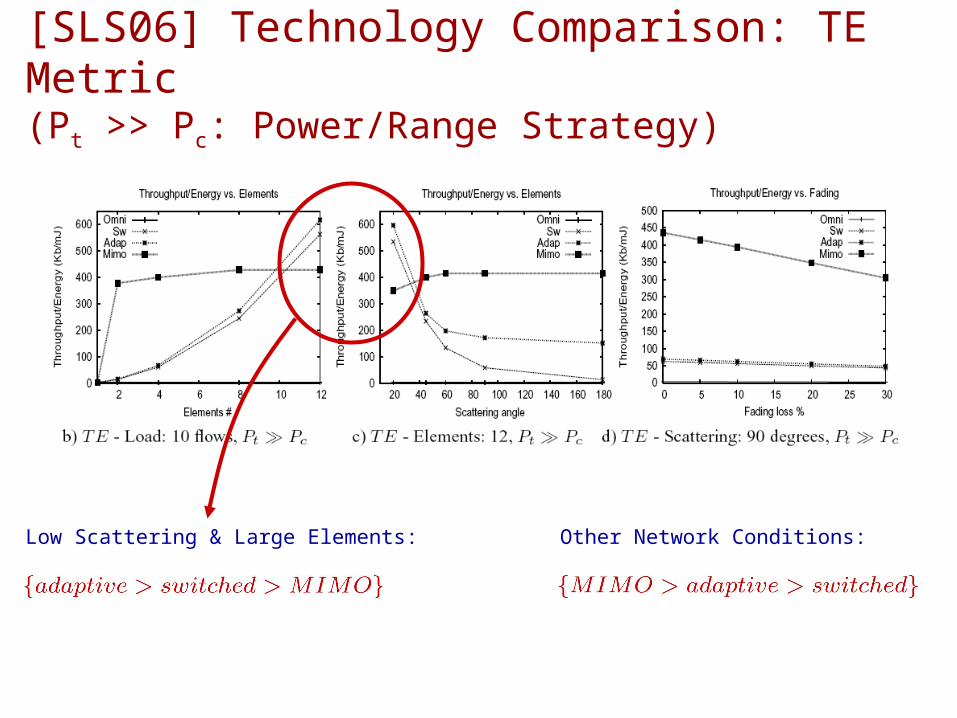
[SLS06] Technology Comparison: TE Metric(Pt >> Pc: Power/Range Strategy)
Other Network Conditions:Low Scattering & Large Elements:

[SLS06] Technology Comparison: TE Metric(Pt ~< Pc: Rate/Range Strategy)
Majority of Network Conditions:


![PHY-layer Spoofing Detection with Reinforcement Learning in ... · in wireless networks. The event detection algorithm proposed in [24] accelerates the event detection in wireless](https://static.fdocuments.us/doc/165x107/5fd4452aa4993062414857eb/phy-layer-spooing-detection-with-reinforcement-learning-in-in-wireless-networks.jpg)