Joint Illumination-Communication Optimization in Visible Light Communication Zhongqiang Yao, Hui...
26
Joint Illumination-Communication Optimization in Visible Light Communication Zhongqiang Yao, Hui Tian and Bo Fan State Key Laboratory of Networking and Switching Technology Beijing University of Posts and Telecommunications (BUPT), China Email: [email protected] Presenter: Zhongqiang Yao
-
Upload
cecil-rice -
Category
Documents
-
view
217 -
download
3
Transcript of Joint Illumination-Communication Optimization in Visible Light Communication Zhongqiang Yao, Hui...

Joint Illumination-Communication Optimization in Visible Light Communication
Zhongqiang Yao, Hui Tian and Bo FanState Key Laboratory of Networking and Switching Technology
Beijing University of Posts and Telecommunications (BUPT), ChinaEmail: [email protected]
Presenter: Zhongqiang Yao

Outlines
2
4 Proposed Algorithm
1 Introduction
2 System Model
5 Simulation
3 Problem Formulation

Outlines
3
1 Introduction

Introduction
4

Introduction
5
Illuminance
VLC
VLC : Visible Light Communication
Communication

Introduction
Motivation
6
Jointly improving the illumination uniformity and communication signal quality is a challenging problem in VLC systems.
Existing works target at achieving uniform SNR or maximizing average SNR.
Conventional evolutionary algorithm (EA) is generally adopted as the optimization tool in references.
The goal is rendering uniform illumination and guaranteeing the minimum SNR threshold.

Outlines
7
1 Introduction
2 System Model

System Model
8
Indoor VLC system

𝑷 (𝑹 𝒋 )=∑𝒊=𝟏
𝑵
{𝒌𝒊𝑷 𝒕𝑯𝒅 (𝟎 ;𝑺𝒊 ,𝑹 𝒋 )+∫𝒌𝒊𝑷 𝒕𝒅𝑯 𝒓𝒆𝒇 (𝟎 ;𝑺𝒊 ,𝑹 𝒋)}
System Model
Received Signal Power
Receiver SNR
9
: the receiver: the LED lighting soruce: the number of LED lighting source: the line-of-sight(LOS) channel gain: the channel LOS gain on the first reflection
𝑺𝑵𝑹 (𝑹 𝒋 )=¿¿: the detector responsivity: the shot noise variance: the thermal noise variance
(1)
(2)

System Model
Illuminance Feature
where is the horizontal illuminance of the light undergoing exactly order reflections.
10
𝑬=∑𝒏=𝟎
∞
𝑬𝒏
𝑬𝒏
𝒏
(3)

Outlines
11
1 Introduction
2 System Model
3 Problem Formulation

Problem Formulation
Optimization Factors The LED lighting source can be adjusted by a corresponding optimization factor
Received Signal Power The Eq.(1) can be rewritten as:
12
𝑷 (𝑹 𝒋 )=∑𝒊=𝟏
𝑵
{𝒌𝒊𝑷 𝒕𝑯𝒅 (𝟎 ;𝑺𝒊 ,𝑹 𝒋 )+∫𝒌𝒊𝑷 𝒕𝒅𝑯 𝒓𝒆𝒇 (𝟎 ;𝑺𝒊 ,𝑹 𝒋)} (4)

Problem Formulation
Evenness Measure Function
13
𝛿 (𝐾 )=100−100(max
𝑗𝑃 (𝑅 𝑗)−min
𝑗𝑃 (𝑅 𝑗)
max𝑗𝑃 (𝑅 𝑗)
)
To facilitate the description, the vectordenotes the optimization factor of the N LED lighting sources.
(5)

Problem Formulation
Mathematical formulation
UIR: The uniformity illuminance ratio (UIR) is defined as the ratio of the minimum to the average illuminance.
14
Subject to:
(6)

Outlines
15
4 Proposed Algorithm
1 Introduction
2 System Model
3 Problem Formulation

Proposed Algorithm
Harmony Annealing algorithm (HA) HA is constructed on the benchmark of improved harmony search (IHS) algorithm and simulated annealing (SA) algorithm.
16
• Weak Stability is poor• Advantage Searching
efficiency is highIHS
• Weak Searching efficiency is poor
• Advantage A powerful global optimization
SA

Proposed Algorithm
Algorithm Flowchart
17
HM: harmony memory,the library of solution vectors
NI: the stopping criterion

Proposed Algorithm
IHS
18
𝒌𝒊
The procedure of generating a new solution vector.
𝑲 𝒏𝒆𝒘
HMCR: help find global solution vectorsPAR: the fine tuning probability

Proposed Algorithm
Algorithm Flowchart
19
is multiply sampled using Metropolis Criterion.

Outlines
20
4 Proposed Algorithm
1 Introduction
2 System Model
5 Simulation
3 Problem Formulation

Simulation
Simulation Parameter
21

Simulation
Convergence curves of the HA, EA, IHS and SA
22
• SA doesn’t arrive in a stable state
• IHS converges after about 3800 iterations
• EA’s convergence speed is 5.3% slower than IHS.
• HA is 50% faster than EA.
Simulation
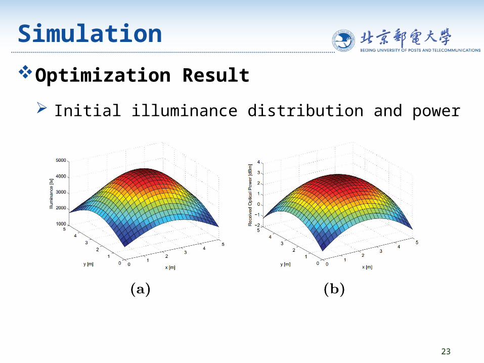
Optimization Result
23
Initial illuminance distribution and power distribution

Simulation Optimized using HA
Optimized using EA
24
• 58.53% from the peak value• UIR is 0.82
• 56.53% from the peak value• UIR is 0.77

Conclusion The optimization scheme works well.
The proposed HA algorithm outperforms EA algorithm.
The universality of HA algorithm is need further verification.
25

26