Joint ABS and user grouping allocation for HetNet with ... Open Access Joint ABS and user grouping...
14
RESEARCH Open Access Joint ABS and user grouping allocation for HetNet with picocell deployment in downlink Wei-Chen Pao 1 , Jhih-Wei Lin 2 , Yung-Fang Chen 2* and Chin-Liang Wang 3 Abstract In order to resolve the co-channel inter-cell interference problem in heterogeneous networks (HetNet), the feature of almost blank subframes (ABS) in the time domain of the enhanced inter-cell interference coordination (eICIC) is utilized. In this paper, an ABS configuration design is developed on downlink in HetNet and the associated resource allocation problem for maximizing the system performance with fairness among user equipments (UEs) is considered. Compared to conventional problems, the resource assignment problems include the configuration of ABS pattern and the resource allocation for macro UEs and pico UEs, which aims to maximize the downlink throughput and balance the traffic offloading in intra-frequency HetNet deployments. First, this paper introduces an ABS pattern design by using the channel condition, which is developed in terms of the time domain resource. Subframes are categorized as protected or normal subframes for reducing interference impact to pico UEs. Based on the configuration of the ABS pattern, we develop a grouping strategy to determine which pico UEs use either protected or normal subframes. Besides, the assignment of resource blocks with respect to the resource in the frequency domain is developed along with the fairness among UEs. The proposed joint allocation scheme takes the system throughput and the fairness into account, and has better performance than the existing schemes. Simulation results also reveal that the performance of the proposed joint allocation scheme approximates the optimal solution with the full search scheme. Keywords: Inter-cell interference coordination, Almost blank subframe, Heterogeneous network, Proportional fairness, Resource allocation 1 Introduction Orthogonal frequency division multiple access (OFDMA) system has been chosen for the next-generation broad- band wireless system standards [1] in order to satisfy the growing demands on the high data traffic in the mobile communication systems. The Third Generation Partner- ship Project (3GPP) Long Term Evolution (LTE) has been regarded as a promising mobile technology with increased system sum rates [2]. The LTE-Advanced (LTE-A) is an evolution of LTE, which achieves International Mobile Telecommunications (IMT)-Advanced requirements [3–5]. With more data traffic demand in the future, enhancing the system spectral efficiency by the deploy- ment of traditional macro eNodeBs (eNBs) has high cost. Therefore, heterogeneous networks (HetNet) have been widely discussed in 3GPP LTE-A standards [6, 7]. HetNet includes high-power macro eNBs and low-power nodes, such as femto eNBs, pico eNBs, and relays [8–10]. In order to offload user equipments (UEs) from a macro eNB to a pico eNB more efficiently, cell range expansion (CRE) has been introduced in 3GPP LTE-A [11]. In the CRE method, a bias value is introduced and added to reference signal received power (RSRP) of pico eNBs. A CRE region is introduced where the system pretends that UEs have better signal quality from the pico eNB. There- fore, the system may tend to offload UEs from the macro eNB to the pico eNB. More UEs may connect to pico eNBs for load balancing. The control of the bias and the related offloading is discussed in [12, 13]. However, the UE which is handed over from the macro eNB to the pico eNB with the CRE technique may suffer severe interfer- ence from the macro eNB since the received signal from * Correspondence: [email protected] 2 Department of Communication Engineering, National Central University, Taoyuan, Taiwan, Republic of China Full list of author information is available at the end of the article © The Author(s). 2017 Open Access This article is distributed under the terms of the Creative Commons Attribution 4.0 International License (http://creativecommons.org/licenses/by/4.0/), which permits unrestricted use, distribution, and reproduction in any medium, provided you give appropriate credit to the original author(s) and the source, provide a link to the Creative Commons license, and indicate if changes were made. Pao et al. EURASIP Journal on Wireless Communications and Networking (2017) 2017:163 DOI 10.1186/s13638-017-0945-9
Transcript of Joint ABS and user grouping allocation for HetNet with ... Open Access Joint ABS and user grouping...

RESEARCH Open Access
Joint ABS and user grouping allocation forHetNet with picocell deployment indownlinkWei-Chen Pao1, Jhih-Wei Lin2, Yung-Fang Chen2* and Chin-Liang Wang3
Abstract
In order to resolve the co-channel inter-cell interference problem in heterogeneous networks (HetNet), the feature ofalmost blank subframes (ABS) in the time domain of the enhanced inter-cell interference coordination (eICIC) is utilized.In this paper, an ABS configuration design is developed on downlink in HetNet and the associated resource allocationproblem for maximizing the system performance with fairness among user equipments (UEs) is considered. Comparedto conventional problems, the resource assignment problems include the configuration of ABS pattern and the resourceallocation for macro UEs and pico UEs, which aims to maximize the downlink throughput and balance the traffic offloadingin intra-frequency HetNet deployments. First, this paper introduces an ABS pattern design by using the channel condition,which is developed in terms of the time domain resource. Subframes are categorized as protected or normal subframes forreducing interference impact to pico UEs. Based on the configuration of the ABS pattern, we develop a grouping strategyto determine which pico UEs use either protected or normal subframes. Besides, the assignment of resource blocks withrespect to the resource in the frequency domain is developed along with the fairness among UEs. The proposed jointallocation scheme takes the system throughput and the fairness into account, and has better performance than theexisting schemes. Simulation results also reveal that the performance of the proposed joint allocation schemeapproximates the optimal solution with the full search scheme.
Keywords: Inter-cell interference coordination, Almost blank subframe, Heterogeneous network, Proportional fairness,Resource allocation
1 IntroductionOrthogonal frequency division multiple access (OFDMA)system has been chosen for the next-generation broad-band wireless system standards [1] in order to satisfy thegrowing demands on the high data traffic in the mobilecommunication systems. The Third Generation Partner-ship Project (3GPP) Long Term Evolution (LTE) has beenregarded as a promising mobile technology with increasedsystem sum rates [2]. The LTE-Advanced (LTE-A) is anevolution of LTE, which achieves International MobileTelecommunications (IMT)-Advanced requirements[3–5]. With more data traffic demand in the future,enhancing the system spectral efficiency by the deploy-ment of traditional macro eNodeBs (eNBs) has high cost.
Therefore, heterogeneous networks (HetNet) have beenwidely discussed in 3GPP LTE-A standards [6, 7]. HetNetincludes high-power macro eNBs and low-power nodes,such as femto eNBs, pico eNBs, and relays [8–10].In order to offload user equipments (UEs) from a macro
eNB to a pico eNB more efficiently, cell range expansion(CRE) has been introduced in 3GPP LTE-A [11]. In theCRE method, a bias value is introduced and added toreference signal received power (RSRP) of pico eNBs. ACRE region is introduced where the system pretends thatUEs have better signal quality from the pico eNB. There-fore, the system may tend to offload UEs from the macroeNB to the pico eNB. More UEs may connect to picoeNBs for load balancing. The control of the bias and therelated offloading is discussed in [12, 13]. However, theUE which is handed over from the macro eNB to the picoeNB with the CRE technique may suffer severe interfer-ence from the macro eNB since the received signal from
* Correspondence: [email protected] of Communication Engineering, National Central University,Taoyuan, Taiwan, Republic of ChinaFull list of author information is available at the end of the article
© The Author(s). 2017 Open Access This article is distributed under the terms of the Creative Commons Attribution 4.0International License (http://creativecommons.org/licenses/by/4.0/), which permits unrestricted use, distribution, andreproduction in any medium, provided you give appropriate credit to the original author(s) and the source, provide a link tothe Creative Commons license, and indicate if changes were made.
Pao et al. EURASIP Journal on Wireless Communications and Networking (2017) 2017:163 DOI 10.1186/s13638-017-0945-9

pico eNB is still weak. A major problem in HetNet [14] isthe cross-tier inter-cell interference (ICI) because the low-power nodes such as pico eNBs share the same frequencyband with the macro eNBs. In order to improve theperformance and reduce the cross-tier interference, amajor feature of enhanced inter-cell interference coordin-ation (eICIC) [10, 15–18] is to coordinate inter-cell inter-ference in time domain by implementing almost blanksubframe (ABS). The method of time-domain multiplex-ing (TDM) using ABS [19, 20] is introduced to avoidheavy ICI on both data and control channels of the down-links. When the ABS scheme is employed, subframes willbe further configured as either normal subframes orprotected subframes. For normal subframes, UEs servedby macro eNBs (macro UEs) and served by pico eNBs(pico UEs) are all allowed to use these subframes. Forprotected subframes, only pico UEs are allowed to usethose subframes. The designs of the CRE region and theABS pattern can be developed to have gain and benefit forthe whole system, such as traffic offloading and throughput.Regarding the above discussion, we focus on the
challenges for maximizing the system performance withfairness among UEs in HetNet which include the config-uration design of the ABS pattern and the resourceallocation for macro UEs and pico UEs in terms of thetime domain resource, i.e., subframe configurationincluding protected subframe and normal subframewhere the resource is located in the time domain, andthe frequency domain resource, i.e., subcarrier allocationto multiple UEs where this resource is located in thefrequency domain. Due to the design of the CRE regionand ABS to protect Pico UEs, the resource allocationproblem becomes more complicated. The ABS patternneeds to be configured and coordinated among eNBs forthe purpose of the maximization of system capacity orthroughput. Also, subcarriers should be properly assignedto macro UEs and Pico UEs. The associated configuration,i.e., a normal or a protected subframe of a particularsubcarrier will determine the amount of the sufferedinterference. We also consider fairness among Pico UEs.Consequently, the proposed resource allocation schemecomprises the ABS configuration, the Pico UE group-ing, and the subcarrier allocation.First, this paper focuses on the design for the configur-
ation of an ABS pattern. The problems of cell selectioncombined with ABS density are investigated in [21–23].The channel state is usually assumed to be time invari-ant in the period of an ABS pattern [24, 25]. Thus, mostof papers only discuss the ABS density without deter-mining which subframes should be configured as pro-tected subframes. The system performance, e.g.,throughput, is affected by the ABS configuration sinceeach subcarrier or each UE experiences different channelcondition. In the view of the time domain, the ABS
pattern design strategy is developed. We utilize thechannel condition to design an evaluation function as anindicator which aims to maximize the sum rate of thesystem. The indicator can efficiently determine whichsubframes should be configured as protected sub-frames. Different from the previous work [22], theABS pattern is dynamically adjusted, instead of fixed.Second, this paper develops a pico UE grouping strategy
based on an optimization technique to determine whichpico UEs use protected subframes or normal subframes.Various schemes of pico UE grouping [24–27] have beeninvestigated in the HetNet with CRE. The simplest way isthat all pico UEs are assigned to use protected subframes[26], which means pico eNBs only work in protectedsubframes. This scheme may cause the reduced perform-ance in pico eNBs due to the limited resources. In [27],some pico UEs which are handovered from a macro eNBto a pico eNB with the CRE technique are assigned to theprotected UE set and others are assigned to the normalUE set. In [25], “brute force search” by employing integerprogramming is used to get the optimal solution for theproblem of the time-domain resource partitioning forenhanced inter-cell interference coordination. However,this scheme has a high computational complexity. Inorder to reduce the computational complexity, onescheme [24] using Nash bargaining solution (NBS) isproposed to reduce the complexity, but the NBS schemeonly finds a sub-optimal solution in some sense. There-fore, it raises our motivation to develop a pico UEgrouping scheme with a low computational complexitywhile approximating the optimal solution. We alsodevelop a strategy for the pico UE grouping to determinewhich pico UEs use either the normal subframes or theprotected subframes. Deviated from the tradition UEgrouping methods [28–30], Pico UEs will be re-distributed by using a fast adjustment in a group basis anda refinement mechanism on a per-UE basis. Accompaniedby the re-distribution, the radio resource blocks in the fre-quency domain are allocated jointly per subframe.Finally, in this paper, we propose joint allocation
scheme to maximize the system performance whileconsidering fairness among UEs by appending someprocessing procedures. A dynamic ABS pattern design isintroduced. Based on the ABS pattern, UE groupingstrategies including the fast adjustment and the refine-ment mechanism are introduced. Meanwhile, the radioresource allocation is executed as well. The proposedscheme outperforms the existing schemes [24, 27] andapproaches the full search scheme [25] while the compu-tational complexity is greatly reduced. The proposedalgorithm is different from other works, such as (1) time-domain resource portioning [23, 24, 27] without usergrouping or subcarrier allocation, (2) fair scheduling[31, 32] without ABS configuration and user grouping,
Pao et al. EURASIP Journal on Wireless Communications and Networking (2017) 2017:163 Page 2 of 14
or (3) user selection and resource allocation algorithm[33] without ABS configuration.Our contributions and new ideas include (a) a joint
allocation scheme is first developed in the time domainand the frequency domain, including the considerationof the proportional fairness among UEs; (b) a new evalu-ation function based on an optimization technique isproposed to determine the configuration of subframes,i.e., normal and protected subframes. A low complexityassociated strategy is thus proposed; (c) another newevaluation function is derived for UE grouping, i.e., ineither the normal or the protected UE set; (d) theproposed scheme outperforms the existing schemes[24, 27], and approaches the optimal solution withthe full search scheme [25].
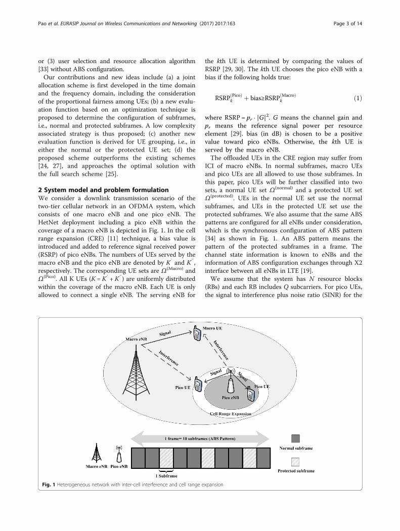
2 System model and problem formulationWe consider a downlink transmission scenario of thetwo-tier cellular network in an OFDMA system, whichconsists of one macro eNB and one pico eNB. TheHetNet deployment including a pico eNB within thecoverage of a macro eNB is depicted in Fig. 1. In the cellrange expansion (CRE) [11] technique, a bias value isintroduced and added to reference signal received power(RSRP) of pico eNBs. The numbers of UEs served by themacro eNB and the pico eNB are denoted by K′ and K″,respectively. The corresponding UE sets are Ω(Macro) andΩ(Pico). All K UEs (K = K′ + K″) are uniformly distributedwithin the coverage of the macro eNB. Each UE is onlyallowed to connect a single eNB. The serving eNB for
the kth UE is determined by comparing the values ofRSRP [29, 30]. The kth UE chooses the pico eNB with abias if the following holds true:
RSRP Picoð Þk þ bias≥RSRP Macroð Þ
k ð1Þ
where RSRP = pr ⋅ |G|2. G means the channel gain and
pr means the reference signal power per resourceelement [29]. bias (in dB) is chosen to be a positivevalue toward pico eNBs. Otherwise, the kth UE isserved by the macro eNB.The offloaded UEs in the CRE region may suffer from
ICI of macro eNBs. In normal subframes, macro UEsand pico UEs are all allowed to use those subframes. Inthis paper, pico UEs will be further classified into twosets, a normal UE set Ω(normal) and a protected UE setΩ(protected). UEs in the normal UE set use the normalsubframes, and UEs in the protected UE set use theprotected subframes. We also assume that the same ABSpatterns are configured for all eNBs under consideration,which is the synchronous configuration of ABS pattern[34] as shown in Fig. 1. An ABS pattern means thepattern of the protected subframes in a frame. Thechannel state information is known to eNBs and theinformation of ABS configuration exchanges through X2interface between all eNBs in LTE [19].We assume that the system has N resource blocks
(RBs) and each RB includes Q subcarriers. For pico UEs,the signal to interference plus noise ratio (SINR) for the
Fig. 1 Heterogeneous network with inter-cell interference and cell range expansion
Pao et al. EURASIP Journal on Wireless Communications and Networking (2017) 2017:163 Page 3 of 14

k″th pico UE on the qth subcarrier of the nth RB at theith subframe can be expressed as:
SINR Picoð Þk″;n;q
i½ � ¼G Picoð Þ
k″;n;qi½ �
��� ���2p Picoð Þk″;n;q
i½ �
N0Δf þ G Macroð Þk″;n;q
i½ ���� ���2ε i½ �p Macroð Þ
k′;n;qi½ �
ð2Þ
where i is the subframe index; G Picoð Þk″;n;q
i½ �denotes the chan-
nel gain between the pico eNB and the k″th pico UE on
the qth subcarrier of the nth RB; p Picoð Þk″;n;q
i½ � is the amount
of power for the k″th pico UE on the qth subcarrier ofthe nth RB; N0 is the AWGN noise power spectral
density; Δfis the subcarrier spacing; G Macroð Þk″;n;q
i½ � denotesthe channel gain between the macro eNB and the k″th
pico UE on the qth subcarrier of the nth RB; p Macroð Þk′;n;q
i½ � isthe amount of power for the k′th macro UE on the qthsubcarrier of the nth RB; ε[i]denotes the binary indica-tor; ε[i] = 1represents that the ith subframe is the normalsubframe; ε[i] = 0represents that the ith subframe is theprotected subframe.In the frequency domain, the basic resource allocation
unit for scheduling is the RB unit. In the time domain,resource allocation scheduling is performed based onthe subframe unit. Therefore, the data rate for the k″thpico UE on the nth RB at the ith subframe can beexpressed as:
r Picoð Þk″;n
i½ � ¼XQq¼1
Δf log2 1þ SINR Picoð Þk″;n;q
i½ �� �
¼r normalð Þk″
i½ �; k″∈Ω normalð Þ
r protectedð Þk″
i½ � k″∈Ω protectedð Þ
8<: ð3Þ
where r normalð Þk″;n
i½ �and r protectedð Þk″;n
i½ � are the data rate for thek″th pico UE on the nth RB in the normal UE set andthe protected UE set, respectively.The sum of the data rate for the k″th pico UE at the
ith subframe can be expressed as:
R Picoð Þk″
i½ � ¼XNn¼1
ρ Picoð Þk″;n
i½ �r Picoð Þk″;n
i½ �
¼XNn¼1
ρ Picoð Þk″;n
i½ �XQq¼1
Δf log2 1þ SINR Picoð Þk″;n;q
i½ �� �
¼
(R normalð Þk″
i½ �; k″∈Ω normalð Þ
R protectedð Þk″
i½ � k″∈Ω protectedð Þ
ð4Þwhere ρ Picoð Þ
k″;ni½ � denotes the binary indicator. ρ Picoð Þ
k″;ni½ � ¼ 1
represents that the nth RB is assigned to the k″thpico UE. R normalð Þ
k″i½ � and R protectedð Þ
k″i½ � are the sum of
data rate for the k″th pico UE in the normal UE set andthe protected UE set, respectively. Note that, if the ithsubframe is normal, R normalð Þ
k″i½ � is evaluated and R protectedð Þ
k″
i½ � equals 0. Similarly, for macro UEs, the SINR for the k′
th macro UE on the qth subcarrier of the nth RB at the ithsubframe can be expressed as:
SINR Macroð Þk′;n;q
i½ � ¼G Macroð Þ
k′;n;qi½ �
��� ���2ε i½ �p Macroð Þk′;n;q
i½ �
N0Δf þ G Picoð Þk′;n;q
i½ ���� ���2p Picoð Þ
k″;n;qi½ �
ð5Þ
The data rate for the k′th macro UE on the nth RB atthe ith subframe can be expressed as:
r Macroð Þk′;n
i½ � ¼XQq¼1
Δf log2 1þ SINR Macroð Þk′;n;q
i½ �� �
: ð6Þ
The sum of the data rate for the k′th macro UE at theith subframe can be expressed as:
R Macroð Þk′
i½ � ¼XNn¼1
ρ Macroð Þk′;n
i½ �r Macroð Þk′;n
i½ �
¼XNn¼1
ρ Macroð Þk′;n
i½ �XQq¼1
Δf log2 1þ SINR Macroð Þk′;n;q
i½ �� �
ð7Þ
where ρ Macroð Þk′;n
i½ � denotes the binary indicator. ρ Macroð Þk′;n
i½ � ¼ 1
represents that the nth RB is assigned to the k′thmacro UE. Therefore, the sum rate of the system is known
asPIi¼1
PK ′
k′¼1
R Macroð Þk′
i½ � þ PK″
k″¼1
R Picoð Þk″
i½ �( )
.
Our goal is to maximize the system performancesubject to the transmit power constraints whileconsidering the fairness among all UEs [31, 32]. Theresource allocation problem for the time domaineICIC is formulated as:
maxε i½ �;ε� i½ �;C
k″;C�k″
(XIi¼1
XK ′
k′¼1
ε i½ �R Macroð Þk′
i½ �R
Macroð Þk′ i½ �
0@ þ
XK″
k″¼1
ε i½ �Ck″Rnormalð Þk″
i½ �R
Picoð Þk″ i½ �
þXK″
k″¼1
ε� i½ �C�k″R protectedð Þk″
i½ �R
Picoð Þk″ i½ �
1CA)
¼XIi¼1
XK ′
k′¼1
ε i½ �R
Macroð Þk′ i½ �
XN
n¼1ρ Macroð Þk′;n
i½ �r Macroð Þk′;n
i½ �
0@
8<:
þXK″
k″¼1
ε i½ �Ck″
RPicoð Þk″ i½ �
XNn¼1
ρ Picoð Þk″;n
i½ �r normalð Þk″;n
i½ �
þXK″
k″¼1
ε� i½ �C�k″
RPicoð Þk″ i½ �
XNn¼1
ρ Picoð Þk″ ;n
i½ �r protectedð Þk″;n
i½ �Þgð8Þ
subject to
Pao et al. EURASIP Journal on Wireless Communications and Networking (2017) 2017:163 Page 4 of 14

Xk′∈Ω Macroð Þ
XNn¼1
XQq¼1
p Macroð Þk′;n;q
i½ �≤P Macroð Þ i½ � ð9Þ
Xk″∈Ω Picoð Þ
XNn¼1
XQq¼1
p picoð Þk″;n;q
i½ �≤P Picoð Þ i½ � ð10Þ
XK ′
k′¼1
ρ Macroð Þk′;n
i½ � ¼ 1; for n ¼ 1;…;N ð11Þ
XK″
k″¼1
ρ Picoð Þk″;n
i½ � ¼ 1; for n ¼ 1;…;N ð12Þ
ε i½ � þ ε� i½ � ¼ 1 ð13Þ
Ck″ þ C�k″ ¼ 1 ð14Þ
where the first term of Eq. (8) is the feasible raterelative to its current average data rate of the macro
UEs coupled with the average data rateRMacroð Þk′ i½ � of
the k′th macro UE; the second term of Eq. (8) is thefeasible rate relative to its current average data rateof the pico UEs which are in the normal UE set
coupled with the average data rateRPicoð Þk″ i½ � of the k″
th pico UE; the third term of Eq. (8) is the feasiblerate relative to its current average data rate of thepico UEs which are in the protected UE set coupled
with the average data rate RPicoð Þk″ i½ � of the k″th pico
UE; the average data rate for macro UEs and picoUEs is defined as:
Rk′ Macroð Þ
iþ 1½ � ¼ 1−1JI
� �R
Macroð Þk′ i½ � þ 1
JIR Macroð Þk′
i½ �
ð15Þ
and
RPicoð Þk″ iþ 1½ � ¼ 1−
1JI
� �R
Picoð Þk″ i½ � þ 1
JIR Picoð Þk″
i½ �: ð16Þ
1=RMacroð Þk′ i½ �and1=R Picoð Þ
k″ i½ � in Eq. (8) are the propor-tional fairness (PF) factors which are introduced to
strike a balance between the system performanceand the fairness among UEs [32]; i is the subframeindex; Iis the number of subframes in one frame; J isthe window size which is the number of the framesin a PF period; ε[i]and ε∗[i]are the binary indicators;ε[i] = 1 (ε∗[i] = 0) represents that the ith subframe be-longs to the normal subframe; ε∗[i] = 1 (ε[i] = 0) rep-resents that the ith subframe belongs to theprotected subframe; Ck″ andC�
k″denote the indicators
for the UE k″ whether it is assigned to the normalUE set or the protected UE set. Ck″ ¼ 1 ( C�
k″¼ 0 )
represents that the k″th pico UE is assigned to thenormal UE set; C�
k″¼ 1 (Ck″ ¼ 0) represents that the
k″th pico UE is assigned to the protected UE set;Eq. (9) represents that the sum of the allocatedpower pk′;n;q Macroð Þ i½ � is less than the total power of the
macro eNBP(Macro)[i]; Eq. (10) represents the trans-mit power constraint of the pico eNB P(Pico)[i]; Eq.(11) denotes that each RB in the macro eNB is onlyallocated to one macro UE; each RB in one eNB isnot allowed to be shared among UEs served in theeNB; Eq. (12) denotes that each RB in the pico eNBis only allocated to one pico UE; Eq. (13) means thateach subframe is only classified as either the normalsubframe or the protected subframe; the sum ofε[i]and ε∗[i] for a particular subframe i is equal to 1;Eq. (14) implies that one pico UE can only be in thenormal UE set or the protected UE set.This resource allocation considered in this paper
contains two main challenges: (a) configuration ofthe ABS pattern, i.e. determines the values of ε[i]and ε∗[i]; and (b) design of pico UE grouping, i.e., de-termines the values of Ck″ and C�
k″. So far, there is
no research for considering these two problemsjointly. We first consider the design of the ABS pat-tern, including how many protected subframes perABS pattern should be configured in the system andwhich subframes should be configured as protectedsubframes. In this paper, we will present a joint so-lution for this resource allocation problem tomaximize the sum rate of the system while main-taining the fairness among UEs. The proposedscheme can achieve balance between the system per-formance and the computational complexity, furthercomprising (a) an ABS pattern design in Section 3;(b) a Pico UE grouping design in Section 4; and (c) ajoint allocation scheme in Section 5. The ABS pat-tern determination is executed at the macro eNBwhile the UE grouping and the joint allocation is ex-ecuted at the pico eNB. The backhaul signalingamong eNBs is required for the communication ofABS patterns. The following is a summary of sym-bols used in the paper along with their explanations.
Pao et al. EURASIP Journal on Wireless Communications and Networking (2017) 2017:163 Page 5 of 14

G Picoð Þk″ ;n;q
the channel gain between the pico eNB and the k″thpico UE on the qth subcarrier of the nth RB
p Picoð Þk″ ;n;q
the amount of power for the k″th pico UE on the qthsubcarrier of the nth RB
G Macroð Þk″ ;n;q
the channel gain between the macro eNB and thek″th pico UE on the qth subcarrier of the nth RB
p Macroð Þk′ ;n;q
the amount of power for the k′th macro UE on theqth subcarrier of the nth RB
ε[i] the binary indicator. Subframe configuration
r normalð Þk″ ;n
the data rate for thek″th pico UE on the nth RB in thenormal UE set
r protectedð Þk″ ;n
the data rate for thek″th pico UE on the nth RB in theprotected UE set
ρ Picoð Þk″ ;n
the binary indicator. RB assignment
Ω(normal) the normal UE set
Ω(protected) the protected UE set
R normalð Þk″
the sum of data rate for thek″th pico UE in thenormal UE set
R protectedð Þk″
the sum of data rate for thek″th pico UE in theprotected UE set
R the average data rate
I the number of subframes in one frame
J the windows size which is the number of theframes in a PF period
Ck″ the indicators for the UE k″ assigned to thenormal UE set
C�k″
the indicators for the UE k″ assigned to theprotected UE set
F(Macro)[i] denotes that the sum rate of all macro UEs in theith subframe
F Picoð Þprotectedð Þ i½ � denotes that the sum rate of pico UEs in the
protected UE set in the ith subframe
F Picoð Þnormalð Þ i½ � denotes that the sum rate of pico UEs in the normal
UE set in the ith subframe
α,β,μ,ψk″ ,ϕk″ , ζk″ ,ζ ′k″ ,λk″
non-negative Lagrangian multipliers
N the number of resource block in a system
Q the number of subcarriers per resource block
3 Proposed ABS pattern designAs mentioned in the introduction section, twoimportant issues need to be considered for the design:(a) the number of the protected subframes per ABSpattern should be determined in the system and (b)which subframes should be categorized as protectedsubframes. The time-invariant channel during a sub-frame is assumed because of the slow time-varying chan-nel [24]. Therefore, we would design the ABS pattern byusing subframe as the processing unit. We assume thatall RBs are available and shared among UEs. Initially,without considering the UE grouping and resource allo-cation in this design phase, the channel information of
all subcarriers in each subframe toward two eNBs in anABS period is used. Our goal is to compare the perform-ance index of each subframe which would be determinedas normal or protected. Three variables are defined as:
F Macroð Þi½ � ¼
XK ′
k′¼1
XNn¼1
XQq¼1
Δf log2 1þ SINR Macroð Þk′;n;q
i½ �� �
;
ð17Þ
F Picoð Þnormalð Þ i½ � ¼
XK″
k′¼1
XNn¼1
XQq¼1
Δf log2 1þ SINR normalð Þk″;n;q
i½ �� �
;
ð18Þ
F Picoð Þprotectedð Þ
i½ � ¼XK″
k″¼1
XNn¼1
XQq¼1
Δf log2 1þ SINR protectedð Þk″;n;q
i½ �� �
;
ð19Þ
where F(Macro)[i]denotes that the sum rate of all macroUEs in the ith subframe; F Picoð Þ
normalð Þ i½ � denotes that the sumrate of pico UEs in the normal UE set in the ithsubframe; F Picoð Þ
protectedð Þ i½ � denotes that the sum rate of picoUEs in the protected UE set in the ith subframe.Therefore, the aggregate sum rate can be rewritten as:
maxε i½ �;ε� i½ �
XIi¼1
ε i½ �F Macroð Þ i½ � þ ε i½ �F Picoð Þnormalð Þ i½ �
�þε� i½ �F Picoð Þ
protectedð Þ i½ ��
ð20Þ
where the objective function (20) is subject to Eqs.(9–10, 13); the maximization is achieved by consideringthe values of ε[i]and ε∗[i] according to the channels ofeach subframe. By using an optimization technique, weobtain the Lagrangian function with the relaxation [35] as:
L i½ � ¼ −XI
i¼1
ε i½ �F Macroð Þ i½ �−ε i½ �F Picoð Þnormalð Þ i½ �−ε� i½ �F Picoð Þ
protectedð Þ i½ �
þXI
i¼1
α i½ �Xk′∈K′
XNn¼1
XQq¼1
pk′;n;q i½ �−P Macroð Þ i½ �0@
1A
þXI
i¼1
β i½ �Xk″∈K″
XNn¼1
XQq¼1
pk″;n;q;l i½ �−P Picoð Þ i½ �0@
1A
þXI
i¼1
μ i½ � ε i½ � þ ε� i½ �−1ð Þ
ð21Þ
where α[i], β[i], and μ[i] are non-negative Lagrangianmultipliers. ε[i] is initially relaxed to be assumed as areal-valued number, and it will be used to determine itsbinary value. After differentiating L[i] with respect toε[i]and ε∗[i], respectively, we have
Pao et al. EURASIP Journal on Wireless Communications and Networking (2017) 2017:163 Page 6 of 14

∂L i½ �=∂ε i½ � ¼ F Macroð Þ i½ � þ F Picoð Þnormalð Þ i½ �−μ i½ � ¼ 0 ð22Þ
and
∂L i½ �=∂ε� i½ � ¼ F Picoð Þprotectedð Þ i½ �‐μ i½ � ¼ 0: ð23Þ
Therefore, we can determine whether the ith subframeshould be classified as the normal subframe or theprotected subframe by considering the differencebetween Eq. (22) and Eq. (23).
ΔF i½ � ¼ F Macroð Þ i½ � þ F Picoð Þnormalð Þ i½ �−F Picoð Þ
protectedð Þ i½ �: ð24Þ
Based on the derived result, ΔF[i] implies that the sumrate difference of the ith subframe configured as thenormal subframe or the protected subframe. If the valueof ΔF[i] is greater than zero, the ith subframe isconfigured as the normal subframe because it mayachieve higher sum rate. Otherwise, the ith subframe iscategorized as the protected subframe. After thedevelopment of the configuration of an ABS pattern, theUE grouping design will be shown in the next section.
4 Proposed UE grouping strategyThe resource allocation problem in the view offrequency domain is considered, especially for pico UEs.An UE grouping strategy is developed based on anoptimization technique to determine which pico UEsuse either the normal subframes or the protectedsubframes. Besides, the issue of proportional fairnessamong UEs is also studied. In this section, by using theABS pattern designed in the previous section, wedevelop a strategy to determine the pico UE groupingwhile considering the fairness among UEs. The pico UEgrouping problem for the maximization of the sum rateof pico eNBs can be formulated by using the second andthe third term of Eq. (8) as:
U Picoð Þ ¼ maxCk″
;C�k″
XIi¼1
XK″
k″¼1
Ck″
RPicoð Þk″ i½ �
XNn¼1
ρ Picoð Þk″;n
i½ �r normalð Þk″;n
i½ �
8><>:þ C�
k″
RPicoð Þk″ i½ �
XNn¼1
ρ Picoð Þk″;n
i½ �r protectedð Þk″;n
i½ �
)
ð25Þwhere the function (25) is subject to Eqs. (9–12, 14);when Ck″ ¼ 1 represents that UE k″ is assigned tothe normal UE set; when C�
k″¼ 1 represents that UE
k″ is assigned to the protected UE set on the picoeNB. However, this optimization problem is NP-hardand has a high computational complexity [24]. Inthis paper, we would analyze the pico UE groupingproblem by using an optimization technique. Theoptimization problem (25) is transformed into thedual domain by forming its Lagrangian dual with
the relaxation [35]. The Lagrangian function isshown as:
L′ i½ � ¼ −XIi¼1
XK″
k″¼1
1
RPicoð Þk″ i½ �
ðCk″Rnormalð Þk″
i½ � þ C�k″R protectedð Þk″
i½ �Þ
þXK″
k″¼1
ψk″XK ′
k′¼1
ρ Macroð Þk′;n
i½ �−1 !
þXK″
k″¼1
ϕk″XK″
k″¼1
ρ Picoð Þk″;n
i½ �−1 !
þXK″
k″¼1
ζ′k″
Xk′∈K″
XNn¼1
XQq¼1
p Macroð Þk′;n;q
i½ �−P Macroð Þ i½ �!
þXK″
k″¼1
ζk″Xk″∈K″
XNn¼1
XQq¼1
p Picoð Þk″;n;q
i½ �−P Picoð Þ i½ �0@
1A
þXK″
k″¼1
λk″ Ck″ þ C�k″−1
� �
ð26Þ
where ψk″ , ϕk″ , ζk″ , ζ′k″ , and λk″ are non-negative La-
grangian multipliers for the constraints (9–12, 14). Theoptimal solution Eq. (25) is achieved when the value ofEq. (26) is maximized. Therefore, the expression of theparameter Ck″ and C�
k″ should be derived, which impliesone pico UE is assigned to one of the UE sets.First, by setting the partial derivative of Eq. (26) with
respect to Ck″ to zero, we have
∂L′ i½ �∂Ck″
¼ 0⇒XIi¼1
1
RPicoð Þk″ i½ �
XNn¼1
ρk″;n;l i½ �r normalð Þk″;n;l
i½ �‐λk″ ¼ 0:
ð27Þ
Then, according to Eq. (8), we can get
XNn¼1
ρk″;n i½ �r normalð Þk″;n
i½ � ¼ R normalð Þk″
i½ �=Ck″ : ð28Þ
By Eqs. (27) and (28), we can get
Ck″ ¼XIi¼1
R normalð Þk″
i½ �= λk″RPicoð Þk″ i½ �
� �: ð29Þ
Similarly, by setting the partial derivative of Eq. (26)with respect to C�
k″to zero, we can get
C�k″ ¼
XIi¼1
R protectedð Þk″
i½ �= λk″RPicoð Þk″ i½ �
� �: ð30Þ
By taking Ck″ (29) and C�k″
(30) into Eq. (14), we obtain
Pao et al. EURASIP Journal on Wireless Communications and Networking (2017) 2017:163 Page 7 of 14

XIi¼1
R normalð Þk″
i½ � þ R protectedð Þk″
i½ �� �
= λk″RPicoð Þk″ i½ �
� �¼ 1
⇒λk″ ¼XIi¼1
R normalð Þk″
i½ � þ R protectedð Þk″
i½ �� �
=R Picoð Þk″ i½ �:
ð31ÞBy taking the expression of λk″ (31) into Eq. (29) and
Eq. (30), respectively, we obtain
Ck″ ¼XIi¼1
R normalð Þk″
i½ �R
Picoð Þk″ i½ �
⋅XIi¼1
RPicoð Þk″ i½ �
R normalð Þk″
i½ � þ R protectedð Þk″
i½ �ð32Þ
and
C�k″ ¼
XIi¼1
R protectedð Þk″
i½ �R
Picoð Þk″ i½ �
⋅XIi¼1
RPicoð Þk″ i½ �
R normalð Þk″
i½ � þ R protectedð Þk″
i½ �:
ð33ÞTherefore, we can determine UE k″ which is assigned
to the normal UE set or the protected UE set bycomparing the difference of Ck″ (32) and C�
k″(33) which
are related to the data rate. The difference of Ck″ (32)and C�
k″(33) is defined as:
ΔCk″ ¼ Ck″−C�k″ : ð34Þ
ΔCk″ is the indicator difference of the normal UE setand the protected UE set when UE k″is assigned tothem. If the value of ΔCk″ is more than zero, UE k″
should be assigned to the normal UE set; otherwise, UEk″ should be assigned to the protected UE set.
5 Proposed joint allocation schemeIn this section, the joint ABS configuration and UEgrouping scheme is described to resolve the resourceallocation problem while achieving high systemperformance and fairness among all UEs. The proposedscheme by utilizing the designed functions includes thedesigns of the ABS pattern, the pico UE grouping, andthe RB allocation. The procedures of the proposedscheme are as follows:The pico UE index is k″ ∈ {1, … ,K″}.iandj are the
subframe index and frame index, respectively. (i, j)denotes
the ith subframe of the jth frame. RMacroð Þk′ i½ � and R
Picoð Þk″ i½ �
are the average date rate of macro UE and pico UE,respectively. One starts from j = 1, j ∈ {1, … , J}, J is thewindow size which is the number of the frames in aPF period.
Step 1: ABS Configuration. Start fromi = 1,i∈ {1, … , I},Iis the number of subframes in one frame. Eachsubframe is determined as the normal subframe or the
protected subframe in one frame. The designedfunction ΔF[i] (24) determines which subframes shouldbe configured as protected subframes in one frame. Inorder to find a better ABS pattern, we may sort thevalues of the designed function (24) in a descendingorder. And then, the number of protected subframes islimited to an upper bound of ABS density [22].Therefore, the ABS pattern for a frame would beconfigured.Step 2: Pico UE Grouping. After the ABS pattern isconfigured for a frame, we will assign pico UEs to thenormal UE set or the protected UE set and allocate theRBs for each subframe. The initial UE set is determinedby using Eq. (1). Pico UEs which are handed over frommacro eNB to pico eNB because of bias values areassigned to the protected UE set Ω(protected), i.e., C�
k″¼ 1. The others are assigned to the normal UE setΩ(normal), i.e., Ck″ ¼ 1.Step 3: RB Allocation, for n = 1, …, N. After theprotected UE set Ω(protected)and the normal UE setΩ(normal)are determined, the RB allocation of eachsubframe is performed. For the normal subframes, onlypico UEs which are assigned to the normal UE set canuse the RBs; similarly, the RBs in the protectedsubframes can only be used by UEs in the protectedUE set. We assume that power is equally distributed toeach RB in the view of base station. In the initial stage,equal power is assumed for each subcarrier of each UE.A simple strategy is to assign RBs to UEs with a highervalue of data rate. Since it is the first run of thesolution, a better solution is achieved after iterations bythe proposed scheme.
For the macro UEs, the nth RB of the ith subframe isallocated to the k ′th macro UE with the maximum valueof the function:
k′^ ¼ argk′∈Ω Macroð Þ
max r Macroð Þk′;n
i½ �=R Macroð Þk′ i½ �
n o: ð35Þ
The nth RB is assigned to the k ′th macro UE denoted
as ρ Macroð Þk′ ;n
i½ � ¼ 1. For the pico UEs in the normal UE set,
the nth RB of the ith subframe which belongs to thenormal subframe is allocated to the k″ th pico normalUE with the maximum value of the function:
k″^ ¼ argk″∈Ω normalð Þ
max r normalð Þk″;n
i½ �=R Picoð Þk″ i½ �
n o: ð36Þ
Similarly, for the pico UEs in the protected UE set, thenth RB of the ith subframe is allocated to the pico UEwith the maximum value of the function:
Pao et al. EURASIP Journal on Wireless Communications and Networking (2017) 2017:163 Page 8 of 14

k″^ ¼ argk″∈Ω protectedð Þ
max r protectedð Þk″;n
i½ �=R Picoð Þk″ i½ �
n o: ð37Þ
The nth RB is determined as ρ Picoð Þk″ ;n
i½ � ¼ 1 for the k″th
pico UE. Repeat Step 3 until all the RBs, for n = 1, ..., N,are allocated in the ith subframe; then, repeat the sameprocess until i = I. The initial sum rate denoted as
U Picoð Þinitialð Þ is calculated according to Eq. (25).
Step 4: Fast Adjustment. We would re-distribute picoUEs into the two UE sets by using Ck″ (32) and C�
k″
(33) in a group basis. If the k″th UE is assigned to thenormal UE set, we can get the Ck″ according to Eq.(32); then, we temporarily move the k″th UE from thenormal UE set to the protected UE set; and repeat Step3 to allocate the RBs for each subframe. We can get theC�
k″ according to Eq. (33). Similarly, if the k″th UE isassigned to the protected UE set, the same approach isused to get Ck″ and C�
k″ . After that, ΔCk″ (34) is obtainedfor each pico UE. The value of ΔCk″would be used todetermine if the k″th UE is re-assigned to the normal UEset or the protected UE set. If ΔCk″≥0, the pico UE k″isassigned to the normal UE set; otherwise, the pico UE k″
is assigned to the protected UE set.
Ck″ ¼ 1 and k″∈Ω normalð Þ ; if ΔCk″≥0
C�k″ ¼ 1 and k″∈Ω protectedð Þ ; if ΔCk″ < 0
(ð38Þ
After the pico UE re-assignment, the updated UE sets,i.e., Ω(normal) and Ω(protected), are obtained. The sum rateU(Pico) according to Eq. (25) is calculated correspond-
ingly. If the value of U(Pico) is larger than that of U Picoð Þinitialð Þ ,
the normal UE set Ω(normal) and the protected UE set
Ω(protected) are updated. Then, update U Picoð Þinitialð Þ as U(Pico)
and repeat Steps 3–4 until the value of U(Pico) is no moreincreased.
Step 5: Refinement Mechanism. Based on the result ofthe fast adjustment, the refinement mechanism isperformed to exchange or move pico UEs between twoUE sets on a per-UE basis. The main concept of the re-finement mechanism is to re-assign only one UE to thenormal UE set Ω(normal) or the protected UE set Ω(pro-
tected) in one iteration. In the exchanging operation, ori-ginally two pico UEs, e.g., xandy, are assignedtoΩ(normal)andΩ(protected), i.e., x∈Ω(normal) andy∈Ω(protected). After the exchanging operation, two picoUEs are exchanged between two pico UE sets, i.e., y∈Ω(normal) and x∈Ω(protected). In this fashion, two picoUEs are exchanged in each time and the number of
pico UEs in each set is not changed. The sum rate (25)of all combinations is calculated correspondingly. Thesum rate increment can be defined as:
ΔU Picoð Þexchangeð Þ ¼ U Picoð Þ
s′ −U Picoð Þinitialð Þ
n os′∈S′
ð39Þ
where S′ denotes all combination cases in the exchangingoperation; s′ is one of combination cases; U Picoð Þ
s′ is thesum rate of the s′th combination case. In the movingoperation, one pico UE is moved from Ω(normal) toΩ(protected) or from Ω(protected) toΩ(normal). After moving,the corresponding sum rate (25) is calculated. The sumrate increment can be defined as:
ΔU Picoð Þmoveð Þ ¼ U Picoð Þ
s″ −U Picoð Þinitialð Þ
n os″∈S″
ð40Þ
where S″ denotes all combination cases in the movingoperation; s″ is one of combination cases; U Picoð Þ
s″ is thesum rate of the s″th combination case. Among allcombinations S′ ∪ S″, one combination with themaximum sum rate increment would be selected toperform the corresponding operation.
s� ¼ arg maxs�∈S′∪S″
ΔU Picoð Þexchangeð Þ
n o∪ ΔU Picoð Þ
moveð Þn o
: ð41Þ
Then, update the sets of Ω(normal) and Ω(protected) and
the initial value U Picoð Þinitialð Þ . Repeat Step 5 until no sum rate
increment can be achieved.
Step 6: Update the average data ratesRMacroð Þk′ i½ �and
RPicoð Þk″ i½ � for the current frame. The proposed joint
scheme is ready to be performed for the nextframej = j + 1. Return to Step 1 until the windowsize of frames j = J is met.
In summary, Fig. 2a is a flow chart of the proposedjoint allocation scheme. The proposed joint allocationscheme is executed on a per frame duration basis. First,ABS configuration for a frame determines eachsubframe as the normal subframe or the protectedsubframe at the macro eNB. The periodicity is a framebasis. The current channel state information may not beinstantly estimated, so that we can use the channelinformation in the previous frame to design the ABSpattern because of the slow time-varying channel appli-cation. After that, the information of ABS configurationexchanges through the X2 interface between the macroeNB and the pico eNB. The X2 interface would be idealbackhaul as the latency may be less than 2.5 μs [36].Therefore, the predicted sum rate can be calculated inthe proposed ABS pattern design. The backhaul signal-ing may comprise the channel information of Pico UEsand the ABS configuration. The proposed Pico UE
Pao et al. EURASIP Journal on Wireless Communications and Networking (2017) 2017:163 Page 9 of 14

grouping strategy is performed locally for each subframe.i.e., pico UEs are assigned into two sets, i.e., the normalUE set or the protected UE set. In the step of Pico UEgrouping, fast adjustment introduced in Section 4 andrefinement mechanism in Section 5 are utilized to separ-ate pico UEs into two groups for achieving betterperformance. The corresponding RB allocation inSection 5 is performed in the macro eNB and the picoeNB respectively. The proposed joint allocation schemein Section 5 combines the above operations to maximizethe sum rate of the system while maintaining thefairness among UEs.We incorporate the computation and evaluation of
related equations into Fig. 2a to complete the allocationprocedures. Figure 2b illustrates the procedures of theproposed joint allocation scheme across the frequencydomain and the time domain.
6 Computational complexity analysisIn this section, we focus on the computationalcomplexity analysis of the RB allocation and UEgrouping strategies in one frame in terms of Big-Ohnotation. All compared schemes are based on the samesystem model, so the computational complexity of calcu-lating the data rate associated with an SINR is the same,which is represented as O(Q) by referring to Eq. (3) andEq. (6). The complexities of the processing steps in thealgorithm are the focus, in terms of calculating the SINRand the data rate.Step 1 of the proposed joint allocation scheme is the
ABS configuration for one frame. Regarding the
proposed ABS pattern design, the calculation of the sumrate for each subframe in one frame is needed.Therefore, the complexity of the proposed ABS patterndesign is O(IK″NQ). Step 2 uses Eq. (1) to determine theinitial UE set. In that, K″ UEs are considered whichrequires O(K″). RB allocation is operated in Step 3. Forthe macro eNB, N RBs are considered for K′ UEs persubframe. One frame contains I subframes. Thecomputational complexity of the RB allocation needsO(INK′Q). For the pico eNB, we assume that K″ UEs areequally distributed in each set. Each set needs thecomplexity of O(INK″Q/2) for the RB allocation.Therefore, O(INK″Q) is required for RA allocation ofthe pico UEs. Step 4 focuses on the moving operation ofthe pico UEs. K″ pico UEs are evaluated along with theRB allocation for one iteration. The complexity iscalculated as O((INK″Q)K″T1). T1 denotes the numberof iterations. The refinement mechanism in Step 5comprises the exchanging operation and the movingoperation. We also assume that the average number ofpico UEs in each set is approximately K″/2. For theexchanging operation, there are (K″/2) ⋅ (K″/2) ≈ (K″)2
possible combinations per iteration. For the movingoperation, the number of combinations is the number oftotal pico UEs K″. Therefore, the complexity of therefinement mechanism along with the RB allocation isO(INK″Q((K″)2 + K″)T2)≈O(IN(K
″)3QT2).T2 is thenumber of iterations. In summary, the complexity of thejoint allocation scheme for one frame is O(K″INQ + K″
+ INQ(K′ + K″) + INQ(K″)2T1 + INQ(K″)3T2)≈O(INQK′ +
INQ(K″)2T1 + INQ(K″)3T2).
Fig. 2 a Flow chart of the proposed joint allocation scheme. b Procedures of the proposed joint allocation scheme
Pao et al. EURASIP Journal on Wireless Communications and Networking (2017) 2017:163 Page 10 of 14
For the compared schemes, the computationalcomplexity of the fixed ABS pattern [22] is O(1) where itfixes the ABS density and determines an ABS pattern atrandom. Regarding pico UE grouping strategies, the fullsearch scheme [25] is to search all UE groupingcombinations of pico UEs in each ABS pattern. The
complexity of all UE grouping combinations is OPK″
j¼1CK″
j
� �≈O 2K
″� �
. So, the total computational
complexity along with RB allocation is O
INQK ′ þ INQK″PK″
j¼1CK″
j
� �≈ O INQK ′ þ INQK″2K
″� �
,
including K′ macro UEs and K″ pico UEs. O(INQK′) is thecomplexity of RA allocation for macro UEs. In [27], picoUE grouping is determined by CRE bias, which requiresO(K″). Therefore, the computational complexity alongwith RB allocation is O(K″ + INQK′ + INQK″). In [24], anindicator which involves the data rate is used to determinethat each UE may be assigned to either the normal UE setor the protected UE set. The computational complexity ofpico UE grouping is O(K″T3). T3 denotes the number ofiterations. So, the total computational complexity alongwith RB allocation is O(INQK′ + INQK″K″T3)=O(INQK
′ +INQ(K″)2T3).
7 Simulation resultsThe simulation results will demonstrate the performanceof the proposed scheme compared to those of theexisting schemes [22, 24, 25, 27]. The network topologyconsists of one macro eNB and one pico eNB based onthe 3GPP case 1 [37]. The radius of the macro eNB is289 m, and the pico eNB is randomly distributed with aminimum distance of 75 m to the macro eNB. Thefrequency selective wireless channel model [38] isemployed. We adopt Jake’s model to generate theRayleigh fading channel. The mobile speed is 4 km/h.The standard deviation of shadowing is 8 dB. N0is−174 dBm/Hz. The channel power of the received signalfor each UE is varied because of the various path lossesat the different locations. The macro path loss model[39] is 128.1 + 37.6*log(d1) in decibels. d1 is inkilometers. The pico path loss model [39] is38 + 30*log(d2) in decibels. d2 is in meters. The carrierfrequency is 2 GHz. UEs are uniformly distributedwithin the coverage of the macro cell with the numbersfrom 12 to 36. Transmit power is 46 dBm for the macroeNB and 30 dBm for the pico eNB. Eight-decibel bias isconsidered for cell range expansion. The downlink FDDsystem is used for simulation with a bandwidth of10 MHz comprising 50 RBs. Each RB has 12 subcarriers.Subcarrier spacing Δfis 15 kHz. The ABS pattern periodis set to be 10 ms, i.e., 10-subframe duration. All resultsare the average values from 600 frames.
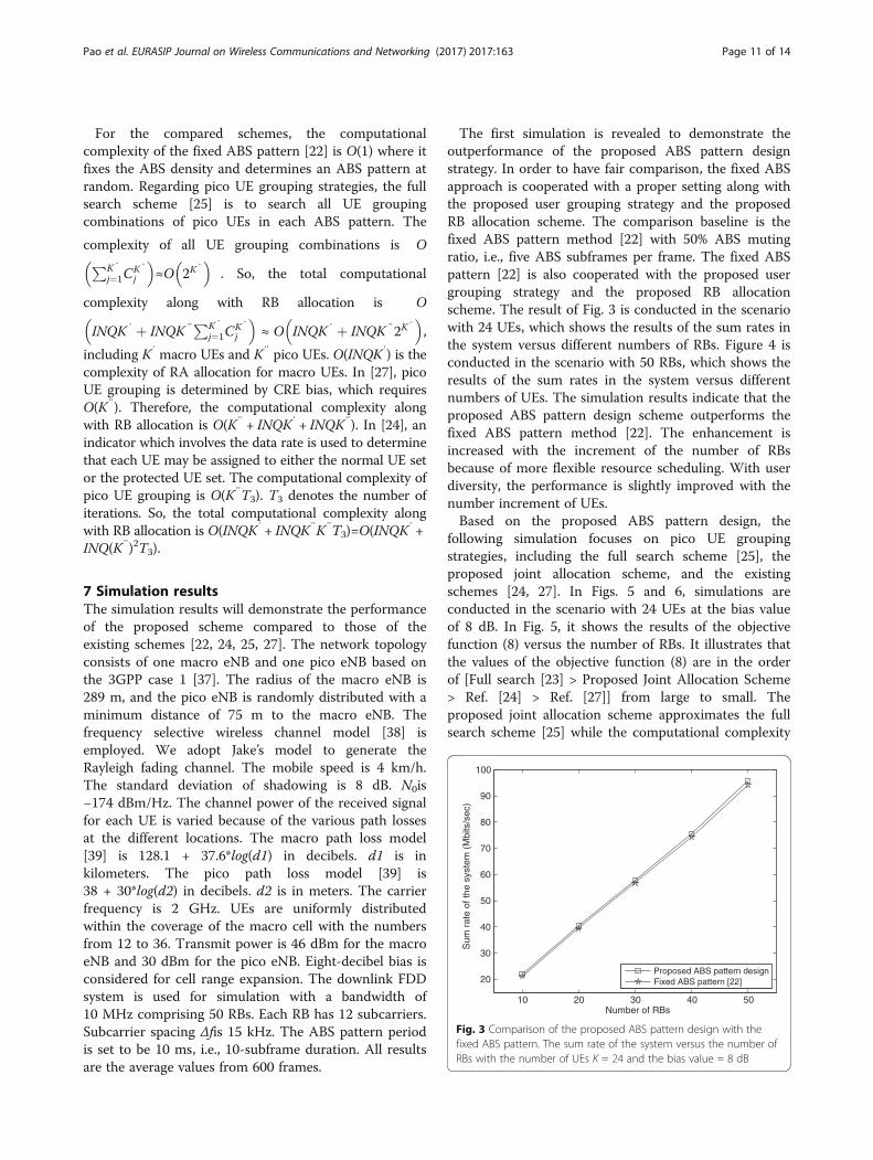
The first simulation is revealed to demonstrate theoutperformance of the proposed ABS pattern designstrategy. In order to have fair comparison, the fixed ABSapproach is cooperated with a proper setting along withthe proposed user grouping strategy and the proposedRB allocation scheme. The comparison baseline is thefixed ABS pattern method [22] with 50% ABS mutingratio, i.e., five ABS subframes per frame. The fixed ABSpattern [22] is also cooperated with the proposed usergrouping strategy and the proposed RB allocationscheme. The result of Fig. 3 is conducted in the scenariowith 24 UEs, which shows the results of the sum rates inthe system versus different numbers of RBs. Figure 4 isconducted in the scenario with 50 RBs, which shows theresults of the sum rates in the system versus differentnumbers of UEs. The simulation results indicate that theproposed ABS pattern design scheme outperforms thefixed ABS pattern method [22]. The enhancement isincreased with the increment of the number of RBsbecause of more flexible resource scheduling. With userdiversity, the performance is slightly improved with thenumber increment of UEs.Based on the proposed ABS pattern design, the
following simulation focuses on pico UE groupingstrategies, including the full search scheme [25], theproposed joint allocation scheme, and the existingschemes [24, 27]. In Figs. 5 and 6, simulations areconducted in the scenario with 24 UEs at the bias valueof 8 dB. In Fig. 5, it shows the results of the objectivefunction (8) versus the number of RBs. It illustrates thatthe values of the objective function (8) are in the orderof [Full search [23] > Proposed Joint Allocation Scheme> Ref. [24] > Ref. [27]] from large to small. Theproposed joint allocation scheme approximates the fullsearch scheme [25] while the computational complexity
10 20 30 40 50
20
30
40
50
60
70
80
90
100
Number of RBs
Sum
rat
e of
the
syst
em (
Mbi
ts/s
ec)
Proposed ABS pattern designFixed ABS pattern [22]
Fig. 3 Comparison of the proposed ABS pattern design with thefixed ABS pattern. The sum rate of the system versus the number ofRBs with the number of UEs K = 24 and the bias value = 8 dB
Pao et al. EURASIP Journal on Wireless Communications and Networking (2017) 2017:163 Page 11 of 14

is greatly reduced. The simulation results also indicatethat the proposed joint allocation scheme outperformsthe existing schemes [24, 27]. Figure 6 shows theperformance comparison in terms of the sum rate of thesystem. The simulation results indicate that theproposed joint allocation scheme still outperforms theexisting schemes [24, 27]. The performance of theproposed joint allocation scheme is much closer to thatof the full search scheme [25].In Figs. 7 and 8, the simulations are in the scenario with
50 RBs by varying the number of total UEs. With thesame performance trend, the proposed joint allocationscheme outperforms the existing schemes [24, 27] interms of the objective function and the sum rate. Theproposed scheme dynamically determines the pico UE
grouping according to the functions (Eqs. 25 and 34),which would indicate the related rate performance of picoUEs. Thus, the proposed joint allocation scheme hasbetter performance than the existing schemes [24, 27].Compared to the full search scheme [25], the performanceloss of the proposed joint allocation scheme is very tiny.Due to the multi-user diversity, the sum rate of the systemis increased as the number of UEs increases. However,under the proportional fairness scheduler, the increase ofthe sum rate would become slow if the numbers of UEsare greater.Figure 9 shows the fairness index (42). Jain’s fairness
index (FI) is a real number in the interval [33] denoted as
FI ¼XK″
k″¼1
R Picoð Þk″
!2
= K″XK″
k″¼1
R Picoð Þk″
� �2 !: ð42Þ
12 18 24 30 3685
90
95
100
105
Number of total UEs
Sum
rat
e of
the
syst
em (
Mbi
ts/s
ec)
Proposed ABS pattern designFixed ABS pattern [22]
Fig. 4 Comparison of the proposed ABS pattern design with thefixed ABS pattern. The sum rate of the system versus the number ofUEs with the number of RBs N = 50 and the bias value = 8 dB
10 20 30 40 500
0.5
1
1.5
2
2.5x 10
7
Number of RBs
Sys
tem
Per
form
ance
(R
t/ave
rage
R)
Full Search Scheme [25]Proposed Joint Allocation Schemeref. [24]ref. [27]
Fig. 5 Comparison of the proposed joint allocation scheme with theexisting schemes. The value of the objective function versus the numberof RBs with the number of UEs K = 24 and the bias value = 8 dB
10 20 30 40 50
20
30
40
50
60
70
80
90
100
110
120
Number of RBs
Sum
Rat
e of
the
Sys
tem
(M
bits
/sec
)
Full Search Scheme [25]Proposed Joint Allocation Schemeref. [24]ref. [27]
Fig. 6 Comparison of the sum rate of the system, in respect to Fig. 5
12 18 24 30 360
0.5
1
1.5
2
2.5x 10
7
Number of total UEs
Sys
tem
Per
form
ance
(R
t/ave
rage
R)
Full Search Scheme [25]Proposed Joint Allocation Schemeref. [24]ref. [27]
Fig. 7 Comparison of the proposed joint allocation scheme with theexisting schemes. The value of the objective function versus the numberof UEs with the number of RBs N = 50 and the bias value = 8 dB
Pao et al. EURASIP Journal on Wireless Communications and Networking (2017) 2017:163 Page 12 of 14
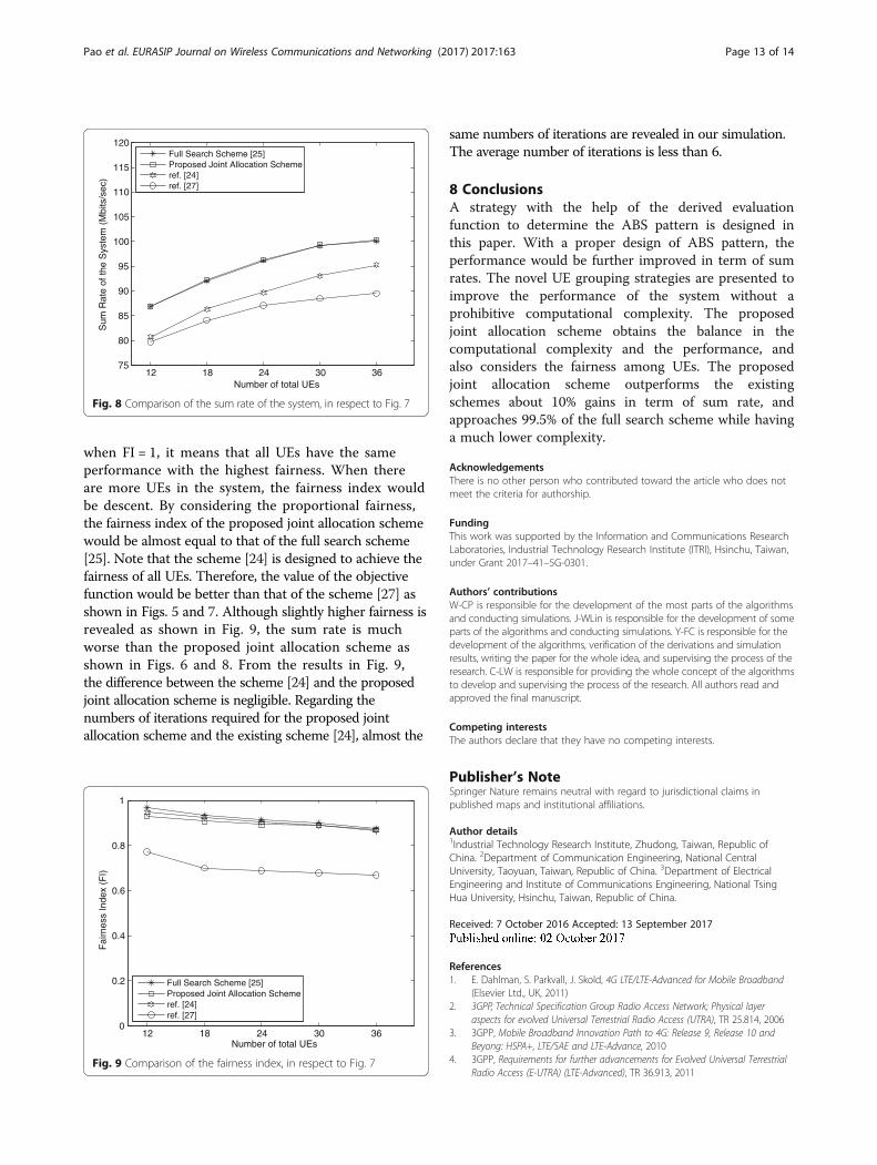
when FI = 1, it means that all UEs have the sameperformance with the highest fairness. When thereare more UEs in the system, the fairness index wouldbe descent. By considering the proportional fairness,the fairness index of the proposed joint allocation schemewould be almost equal to that of the full search scheme[25]. Note that the scheme [24] is designed to achieve thefairness of all UEs. Therefore, the value of the objectivefunction would be better than that of the scheme [27] asshown in Figs. 5 and 7. Although slightly higher fairness isrevealed as shown in Fig. 9, the sum rate is muchworse than the proposed joint allocation scheme asshown in Figs. 6 and 8. From the results in Fig. 9,the difference between the scheme [24] and the proposedjoint allocation scheme is negligible. Regarding thenumbers of iterations required for the proposed jointallocation scheme and the existing scheme [24], almost the
same numbers of iterations are revealed in our simulation.The average number of iterations is less than 6.
8 ConclusionsA strategy with the help of the derived evaluationfunction to determine the ABS pattern is designed inthis paper. With a proper design of ABS pattern, theperformance would be further improved in term of sumrates. The novel UE grouping strategies are presented toimprove the performance of the system without aprohibitive computational complexity. The proposedjoint allocation scheme obtains the balance in thecomputational complexity and the performance, andalso considers the fairness among UEs. The proposedjoint allocation scheme outperforms the existingschemes about 10% gains in term of sum rate, andapproaches 99.5% of the full search scheme while havinga much lower complexity.
AcknowledgementsThere is no other person who contributed toward the article who does notmeet the criteria for authorship.
FundingThis work was supported by the Information and Communications ResearchLaboratories, Industrial Technology Research Institute (ITRI), Hsinchu, Taiwan,under Grant 2017–41–5G-0301.
Authors’ contributionsW-CP is responsible for the development of the most parts of the algorithmsand conducting simulations. J-WLin is responsible for the development of someparts of the algorithms and conducting simulations. Y-FC is responsible for thedevelopment of the algorithms, verification of the derivations and simulationresults, writing the paper for the whole idea, and supervising the process of theresearch. C-LW is responsible for providing the whole concept of the algorithmsto develop and supervising the process of the research. All authors read andapproved the final manuscript.
Competing interestsThe authors declare that they have no competing interests.
Publisher’s NoteSpringer Nature remains neutral with regard to jurisdictional claims inpublished maps and institutional affiliations.
Author details1Industrial Technology Research Institute, Zhudong, Taiwan, Republic ofChina. 2Department of Communication Engineering, National CentralUniversity, Taoyuan, Taiwan, Republic of China. 3Department of ElectricalEngineering and Institute of Communications Engineering, National TsingHua University, Hsinchu, Taiwan, Republic of China.
Received: 7 October 2016 Accepted: 13 September 2017
References1. E. Dahlman, S. Parkvall, J. Skold, 4G LTE/LTE-Advanced for Mobile Broadband
(Elsevier Ltd., UK, 2011)2. 3GPP, Technical Specification Group Radio Access Network; Physical layer
aspects for evolved Universal Terrestrial Radio Access (UTRA), TR 25.814, 20063. 3GPP, Mobile Broadband Innovation Path to 4G: Release 9, Release 10 and
Beyong: HSPA+, LTE/SAE and LTE-Advance, 20104. 3GPP, Requirements for further advancements for Evolved Universal Terrestrial
Radio Access (E-UTRA) (LTE-Advanced), TR 36.913, 2011
12 18 24 30 3675
80
85
90
95
100
105
110
115
120
Number of total UEs
Sum
Rat
e of
the
Sys
tem
(M
bits
/sec
)
Full Search Scheme [25]Proposed Joint Allocation Schemeref. [24]ref. [27]
Fig. 8 Comparison of the sum rate of the system, in respect to Fig. 7
12 18 24 30 360
0.2
0.4
0.6
0.8
1
Number of total UEs
Fai
rnes
s In
dex
(FI)
Full Search Scheme [25]Proposed Joint Allocation Schemeref. [24]ref. [27]
Fig. 9 Comparison of the fairness index, in respect to Fig. 7
Pao et al. EURASIP Journal on Wireless Communications and Networking (2017) 2017:163 Page 13 of 14

5. 3GPP, Further advancements for E-UTRA physical layer aspects, TR 36.814,2010
6. A. Khandekar, N. Bhushan, J. Tingfang, V. Vanghi, in Proc. European WirelessConf. LTE-Advanced: heterogeneous networks (2011), pp. 978–982
7. A. Prasad, O. Tirkkonen, P. Lunden, O.N.C. Yilmaz, L. Dalsgaard, C. Wijting,Energy-efficient inter-frequency small cell discovery techniques for LTE-advanced heterogeneous network deployments. IEEE Commun. Mag. 51(5),72–81 (2013)
8. V. Chandrasekhar, J.G. Andrews, Femtocell networks: a survey. IEEECommun. Mag. 46(9), 59–67 (2008)
9. A. BouSaleh, S. Redana, B. Raaf, J. Hämäläinen, in Proc. IEEE VehicularTechnology Conf.-Fall. Comparison of relay and pico eNB deployments inLTE-advanced (2009), pp. 1–5
10. 3GPP, Evolved Universal Terrestrial Radio Access (E-UTRA); Mobilityenhancements in heterogeneous networks (Release 11), TR 36.839, 2012
11. R1-100701, in 3GPP TSG RAN WG1 Meeting#59. Importance of Serving CellSelection in Heterogeneous Networks (2010)
12. Y. Song, P.Y. Kong, Y. Han, Minimizing Energy Consumption through TrafficOffloading in a HetNet with 2-class Traffic. IEEE Commun. Lett. 19(8), 1394–1397 (2015)
13. P.Y. Kong and G. K. Karagiannidis, “Backhaul-Aware Joint Traffic Offloadingand Time Fraction Allocation for 5G HetNets”, IEEE Transactions on VehicularTechnology, DOI: https://doi.org/10.1109/TVT.2016.2517671, 2016
14. A. Damnjanovic et al., A survey on 3GPP heterogeneous networks. IEEEWirel. Commun. 18(3), 10–21 (2011)
15. D. Luo, B. Li, D. Yang, in Proc. IEEE Vehicular Technology Conf.-Fall.Performance evaluation with range expansion for heterogeneous networks(2011), pp. 1–5
16. R1-112543, “Scenarios for eICIC evaluations,” 3GPP TSG-RAN WG1 Meeting#66,2011
17. R1-106143, “Details of eICIC in macro-pico case,” 3GPP TSG-RAN WG #63,2010
18. R1-110175, “Remaining issues of Rel-10 eICIC,” 3GPP TSG-RAN WG1#63bis,2011
19. D. Lopez-Perez, I. Guvenc, G.D.L. Roche, M. Kountouris, T.Q.S. Quek, J. Zhang,Enhanced intercell interference coordination challenges in heterogeneousnetworks. IEEE Wirel. Commun. 18(3), 22–30 (2011)
20. 3GPP, Evolved Universal Terrestrial Radio Access (E-UTRA) and Evolved UniversalTerrestrial Radio Access Network (E-UTRAN); Overall description; Stage 2(Release 13), TS 36.300, 2015
21. J. Oh, Y. Han, in Proc. IEEE Int. Symposium on Personal Indoor and MobileRadio Commun. Cell selection for range expansion with almost blanksubframe in heterogeneous networks (2012), pp. 653–657
22. Y. Wang, K.I. Pedersen, in Proc. IEEE Vehicular Technology Conf.-Spring.Performance analysis of enhanced Inter-cell Interference Coordination inLTE-Advanced heterogeneous networks (2012), pp. 1–5
23. S. Deb, P. Monogioudis, J. Miernik, J.P. Seymour, Algorithms for enhancedInter-cell Interference Coordination (eICIC) in LTE HetNets. IEEE/ACM Trans.Networking 99, 1 (2013)
24. L. Jiang, M. Lei, in Proc. IEEE Int. Symposium on Personal, Indoor and MobileRadio Commun. Resource allocation for eICIC scheme in heterogeneousnetworks (2012), pp. 448–453
25. J. Pang, J. Wang, D. Wang, G. Shen, Q. Jiang, J. Liu, in Proc. IEEE WirelessCommun. and Networking Conf. Optimized time-domain resourcepartitioning for enhanced inter-cell interference coordination inheterogeneous networks (2012), pp. 1613–1617
26. R1-100142, “System performance of heterogeneous networks with rangeexpansion,” 3GPP TSG-RAN WG1 Meeting#59bis, 2010
27. R1-112411, “Scenarios for further enhanced non ca-based icic for lte,” 3GPPTSG RAN WG1 Meeting#66, 2011
28. A. Weber, O. Stanze, in Proc. IEEE Int. Conf. Commun. Scheduling strategiesfor HetNets using eICIC (2012), pp. 6787–6791
29. 3GPP, Evolved Universal Terrestrial Radio Access (E-UTRA); Physical channelsand modulation, TR 36.211, 2011
30. 3GPP, Evolved Universal Terrestrial Radio Access (E-UTRA); Physical layer –Measurements, TR 36.214, 2010
31. H. Seo, B.G. Lee, in Proc. IEEE Global Telecommun. Conf. A proportional-fairpower allocation scheme for fair and efficient multiuser OFDM systems, vol6 (2004), pp. 3737–3741
32. H. Kim, Y. Han, A proportional fair scheduling for multicarrier transmissionsystems. IEEE Commun. Lett. 9(3), 210–212 (2005)
33. V.D. Papoutsis, I.G. Fraimis, S.A. Kotsopoulos, User selection and resourceallocation algorithm with fairness in MISO-OFDMA. IEEE Commun. Lett.14(5), 411–413 (2010)
34. R1-105406, in 3GPP TSG RAN WG1 meeting#62bis. Support of time domainicic in rel-10 (2010)
35. S. Boyd, L. Vandenberghe, Convex Optimization (Cambridge University Press,2004)
36. 3GPP, Technical Specification Group Radio Access Network; Scenarios andrequirements for small cell enhancements for E-UTRA and E-UTRAN (Release12), TR 36.932, 2013
37. 3GPP, Evolved Universal Terrestrial Radio Access (E-UTRA); Furtheradvancements for E-UTRA physical layer aspects (Release 9), TS 36.814, 2010
38. L. Dong, G. Xu, H. Ling, in Proc. IEEE Global Telecommun. Conf. Prediction offast fading mobile radio channels in wideband communication systems, vol6 (2001), pp. 3287–3291
39. 3GPP, LTE; Evolved Universal Terrestrial Radio Access (E-UTRA); Radio Frequency(RF) requirements for LTE Pico Node B, TR 36.931, 2011
Pao et al. EURASIP Journal on Wireless Communications and Networking (2017) 2017:163 Page 14 of 14