JOINING TIMBER WITH GLASS FIBRE AND EPOXY. Peter Claisse ... papers/Paper 29.pdf · JOINING TIMBER...
24
JOINING TIMBER WITH GLASS FIBRE AND EPOXY. Peter Claisse and Bruno Masse Civil Engineering Group, Coventry University, Priory Street, Coventry, CV1 5FB Phone: 024 7688 8881, Fax 024 7688 8296 Email: [email protected] Abstract Wood-Glass-Epoxy joints are made by wetting glass fibre cloth with epoxy resin and bonding it to the sides of the timbers. They represent an economic alternative to punched metal plates or bolts in a variety of applications including those where high durability, waterproofing or an attractive appearance are required. They may also be used to enhance the properties of the timber members themselves. Previously published work has shown that these joints perform well in fatigue. This paper presents test results for strength and stiffness for a number of different joint configurations with the timbers parallel and at 30, 60 and 90 degrees to each other. The results indicated that uniaxial glass cloth performs better than biaxial glass cloth in all joints. Mis-aligning the glass with the direction of loading has a significant detrimental effect on performance. For the non-parallel joints the unavoidable effect of loading at an angle to the grain reduced both the failure loads and the stiffness. Introduction
Transcript of JOINING TIMBER WITH GLASS FIBRE AND EPOXY. Peter Claisse ... papers/Paper 29.pdf · JOINING TIMBER...

JOINING TIMBER WITH GLASS FIBRE AND EPOXY.
Peter Claisse and Bruno Masse
Civil Engineering Group, Coventry University, Priory Street, Coventry, CV1 5FB
Phone: 024 7688 8881, Fax 024 7688 8296 Email: [email protected]
Abstract
Wood-Glass-Epoxy joints are made by wetting glass fibre cloth with epoxy resin and
bonding it to the sides of the timbers. They represent an economic alternative to
punched metal plates or bolts in a variety of applications including those where high
durability, waterproofing or an attractive appearance are required. They may also be
used to enhance the properties of the timber members themselves. Previously
published work has shown that these joints perform well in fatigue. This paper
presents test results for strength and stiffness for a number of different joint
configurations with the timbers parallel and at 30, 60 and 90 degrees to each other.
The results indicated that uniaxial glass cloth performs better than biaxial glass cloth
in all joints. Mis-aligning the glass with the direction of loading has a significant
detrimental effect on performance. For the non-parallel joints the unavoidable effect
of loading at an angle to the grain reduced both the failure loads and the stiffness.
Introduction
cbx054
Text Box
For citation information please see http://www.claisse.info/Publish.htm

Bonded glass fibre represents an attractive option for joining timber in some structural
applications. The glass is thoroughly wetted with the liquid resin and sets to form a
composite which is bonded to the timbers. Punched metal connectors give excellent
performance for light to medium weight timber frames at very low cost but glass-
epoxy could be competitive in the following circumstances:
• Site applications where access is limited. The epoxy does not need to be
pressed or nailed into the timber.
• Situations where the timber members need to be reinforced. The glass-epoxy
may be used to reinforce the tension face or wrap entire members to improve
their performance.
• External applications which may require protection for the timber. An
ultraviolet stabilised epoxy will provide good protection against all forms of
rot.
• If there is a requirement to prevent water ingress a glass-epoxy coating can be
used over an entire structure. This is the basis for its popularity for boat
building.
• Applications where the structure requires a good appearance. The glass is a
white cloth as supplied but when wetted with the resin it becomes transparent
and the completed composite gives the appearance of a varnish.
The authors have previously published work in which glass-epoxy joints were
compared to other jointing systems such as bolts and dowels (1) and also a study of
the fatigue resistance of the joints (2). In both of these studies the glass-epoxy
performed well but all of the samples were straight butt joints with the weave of the

glass parallel to the grain of the timber. In this paper results are presented for the
strength of joints with different configurations.
Literature Review
Using glass fibre to reinforce wood materials began in the early 1960s (3,4). Wood-
glass fibre composite beams were analysed in elastic deflection but also in the plastic
region (4). Various species of wood were reinforced by applying unidirectional glass
fibre strands impregnated with epoxy resin to the top and bottom surface.
Further studies were developed for laminated timber using different kind of adhesive
(polyester, vinyl-ester and phenol-resorcinol resins) as described in the excellent
review from reference (5). This also mentioned research for wood/glass fibre
composites in other applications:
• Glass Fibre Reinforced Plastics (GFRP) were used to reinforce wood
transmission poles in the early 1970s.
• Plywood was overlaid with glass fibre (an in-depth series of tests was
performed by the American Plywood Association in 1972 and 1973). This
reinforced board was used in the transportation industry and was extensively
used in cargo shipping containers, railroad cars and vans.
• An extensive study was performed in Germany using solid wood, plywood
and particleboard in 1974-1976. GFRP incorporating a polyester resin was
bonded to the surfaces of the core material in a wet process. A considerable
improvement in the strength and the stiffness properties was obtained and a
significant reduction in creep was reported.
A study (6) was carried out using glass fibre with phenol-resorcinol formaldehyde
resin to increase the tension and bending strength of impression finger joints.
Composite members were made of a core wood material (finger joint) with veneers on
each side and glass fibre layers sandwiched between veneer and core. The strengths
were increased from 10 to 40% over unreinforced joints, using only a glass fibre
reinforcement level of 3.5% and 7% by volume. It was noticed that a maximum of
80% of the glass fibre strength capacity was effective in these tests.
The use of composite fabrics to reinforce wood crossties (sleepers) was investigated
(7). The authors investigated the feasibility of hand wrapping for GFRC (Glass Fibre
Reinforced Composites)/wood crosstie and experimentally evaluated their mechanical
behaviour. Northern red oak wood and unidirectional E-glass/epoxy reinforcement
were used. Results of the experimental tests indicated that only one layer of
reinforcement provided noticeable enhancement to both strength and stiffness.
Average increases in stiffness of 15 to 41% and strength of
14 to 31% were achieved.
The same year, the same team (8) produced a paper about accelerated ageing of
wood-composites members. Using red oak wood as a core and two types of composite
fabrics (glass and carbon) as external reinforcements, they undertook series of shear
strength tests. Several adhesives for bonding were used. The results showed that
phenolic-based resins had higher retention of shear strength after being subjected to
ageing conditions. The ageing process was composed of six cycles of swelling and
shrinkage effects. The best combinations were wood/glass/epoxy and
wood/carbon/epoxy, which retained nearly 50% of their shear strength capacity after
the ageing process.
The performance of fibre reinforced polymer composites used with wood has been
reviewed (9). Strength, stiffness and accelerated ageing response of sawn and
laminated wood beams wrapped with glass composites and bonded in place with
polymeric resins were reported. The authors concluded that hybrid wood components
exhibit increases in strength and stiffness of up to 40 and 70% respectively, over non-
wrapped wood beams for a constant volume percent of fabric. These mechanical
properties could be increased further with the addition of more layers of fabric.
No references have been found in the literature to work exactly similar to that
presented in this paper.
Sample fabrication.
The timber samples were European Spruce graded C16 to C24 to BS5268 Part 2 (10).
The samples had a nominal cross section of 100mm by 50mm. Unidirectional glass
fibre woven roving weighing 500g/m2 (SP Systems product code UT-E500 (11)) was
selected for some of the joints. In this cloth almost all of the fibres are uni-directional
with just a very light weave across them to hold them in place during fabrication. For
the other joints a Bi-Axial cloth weighing 450 g/m2 (XE-450) with equal weights of
glass in the warp and the weft was used. The epoxy was a clear coating/laminating

resin (SP Systems product code Spabond 120 (11)) which was used with slow
hardener at the recommended ratio of 100:44 by weight.
The wood/glass/epoxy samples were made of two pieces of timber with a length of
glass fibre/epoxy on each side and were tested with the load applied axially to the
grain direction of one of the timbers (12). For the load parallel to the grain tension
tests and the 90 degrees grain/load angle, the length of composite was of 200 mm. It
was 232 mm long for the 60 degrees and 400 mm long for the 30 degrees. The glass
was only applied to the 100mm wide faces of the samples. The area of the joint was
coated with wet resin, the glass was then positioned and resin stippled into it with a
brush and then the completed joint was consolidated with a roller to expel any
possible remaining air. Direct bond between the two pieces of timber was not
required so no resin was introduced into the joint and foil was used to prevent any
bond from forming. An example of a completed joint is shown in figure 1.
At the ends of the assembled samples two shear-plate connectors were held between
two steel plates and connected with a 20 mm diameter bolt in order to apply the loads.
This system was used in previous testing programmes for timber joints (1, 2, 12). The
minimum distance from the connectors to the tested joint (i.e. glass fibre/epoxy
layers) was 300 mm.
PVC and steel brackets were glued onto the timber in order to hold Linear Variable
Differential Transformers (LVDTs) in position. The LVDTs measured displacements
at the gap position between the brackets located on either piece of timber. On the
parallel samples they were fixed in a symmetrical arrangement to check any

misalignment of the sample. A typical arrangement for a non-parallel sample is
shown in figure 2.
Testing Programme
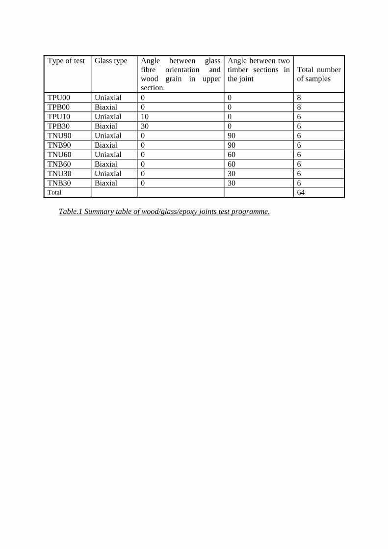
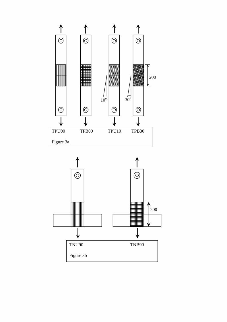
A total of 64 wood/glass/epoxy joints samples were tested. Details are given in table
1 and diagrams of the different configurations are given in figure 3. The samples
coded P were parallel (straight) tests while those coded N were Non-parallel. Those
coded U uses Uni-axial glass while those coded B used bi-axial glass.
Testing was carried out with a hydraulic jack on the strong-floor. Figure 4 shows the
loading arrangement for the non-parallel samples which included a pinned joint in the
loading box to ensure axial loading.
The rig was loaded until the sample was effectively held (i.e. a small load was applied
to the sample). At this stage, the LVDTs were initialised through the data acquisition
system as zero position. A testing sequence using a pre-load was used as specified in
BS EN 26891 (figure 5). Using a loading rate of 6 kN/min, the load was constantly
applied to the sample. The load and displacements were recorded at every 1.5 kN
increment (every 15 sec.) and as the load came closer to the estimated failure load,
they were recorded at every 0.6 kN increment (every 6 sec.).
A typical load-displacement curve is shown in figure 6. The joint stiffness was
calculated over the elastic range of the sample. When the results were analysed some
curves showed a change in slope (or stiffness) in the elastic range with a sudden

increment of displacement. This was due to the failure in tension of some epoxy resin
infiltrated accidentally between the timber piece butt ends (in the gap) and was
excluded from the results for calculation of stiffness.
Results
The results for strength and stiffness are shown in figures 8,9,12 and 13. The length
of the error bars is one standard deviation.
The parallel samples with uniaxial glass failed by delamination of the composite
layers from the timber surface on both sides. A typical failure is shown in figure 7.
The TPU10 samples with the glass at 10o had failure loads more than 15% lower and
stiffness more than 25% lower than for the TPU00 test (figures 8 and 9). The slight
mis-orientation of fibres weakened the system significantly. The same mode of failure
by delamination occurred for TPU10 tests, revealing that the tension strength of the
composite matrix was still higher than the bond strength. The maximum slip in the
gap at failure did not exceed 0.75 mm for the TPU10 test, which is to be compared
with the maximum slip of 1.1 mm for TPU00 test. The load-displacement data
showed that the TPU10 samples did not reach a plastic behaviour and remained in an
elastic/plastic stage until failure.
The modes of failure observed for TPB00 tests were both tension rupture of the fibres
and delamination. This is consistent with the failure loads obtained from the TPB00
test being lower than for TPU00 tests due to the decrease in the amount of glass in the
biaxial cloth carrying the load. The elongation of each fibre for the TPB00 samples in

the load direction was significant, resulting in a high slip in the gap area, with a
maximum of 1.2 mm, a similar value to TPU00 test. High slip but lower failure load
gave the TPB00 tests a lower stiffness than the TPU00 test, as shown in figure 9.
The modes of failure for the TPB30 samples were similar to the TPB00 test and were
tension failure of the fibres and partial delamination. As a result, transverse rupture of
the fibres was observed (due to the combined failure modes), following the
orientation to the load direction (30 degrees). The failure load was generally 20%
lower than for the TPB00 test. Once again, it seemed that premature failure was due
to the fibre orientation, which weakened the joint significantly. The slip-load curves
showed an elastic and plastic behaviour before failure. The maximum displacement
did not exceed 0.8 mm, a much smaller value than for the TPB00 test. The stiffness
based on elastic behaviour was only 10% less than for the TPB00 test. The fact that
both strand directions of fibres were bonded to the timber with an angular orientation
to the load (unlike TPB00 configuration where only one strand direction is loaded)
improved the stiffness of the system.
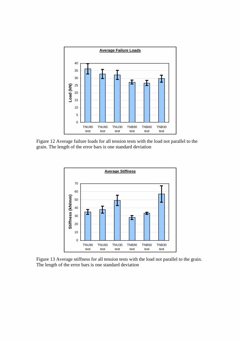
For the non-parallel joints there were major differences between the TNU (uniaxial
glass fibres) and the TNB (biaxial glass fibres) systems. The modes of failure
observed for both systems were clearly different. The TNU tests always failed by
delamination of the composite (figure 10), whereas the TNB tests failed by
combination of delamination and tension rupture of the composite (figure 11). This
observation was confirmed by the fact that failure loads for the TNB tests were lower
than failure loads for the TNU tests, whatever angle configuration was considered
(figure 12). For the TNU tests, all the fibres of the uniaxial glass were orientated in
the load direction: With fewer fibres available to transfer the loads, the TNB tests
failed at lower loads, whether it was delamination failure or fibre rupture.
The increased bond area for the 30o and 60o samples would have been expected to
give them a higher strength but this was not observed for the TNU and TNB tests.
For the TNU tests, where the joints were clearly unbalanced (the joints always failed
by Delamination), the failure loads decreased as the grain/load angle reduced from 90
to 30 degrees. In this situation, the longer the composite layers, the lower the failure
loads. The grain orientation was an important parameter to take into account. Failure
by delamination always occurred on the timber members, where the composite was
orientated with an angle to the grain. This indicated that the bond strength of the
composite was reduced when the timber grain was not orientated in the same direction
than the composite fibres and the loading. When the fibres were orientated
perpendicular to the timber grain direction such as the TNU90 test, it is clear that this
system was the strongest in terms of failure loads, as shown in
figure 12. The average failure loads decrease as the angle to the grain reduces. But
this reduction is not as significant as it could be, if the length of composite were equal
for all the TNU tests.
The situation was rather different for the TNB tests. The modes of failure were less
consistent and were generally combinations of various modes, such as fibre tension
rupture, delamination and longitudinal shear failures. As a result, the failure loads did
not decrease as the grain/load angle reduced from 90 to 30 degrees. The failure loads
appeared to be fairly uniform for the TNB90 and TNB60 tests, and slightly higher for

TNB30. This inconsistency was probably due to the fact that only one half of the
fibres were directly stressed in tension, then the tension capacity of the composite was
lower than for the TNU tests. Furthermore, the biaxial fabric XE450 used for the TNB
tests had two layers of fibres, skewed and stitched together, one on top of the other.
Because the fibres were not woven, the bond between the composite and the timber
only affected the layer of fibres in direct contact with the interface. This was certainly
a reducing factor of the composite bond strength for the TNB tests. With lower bond
and tension strengths, the length of composite became a major factor in the strength of
the joint. Longer strands of fibres improved the bond strength significantly, but the
grain orientation was still having a reducing effect on it.
The timber grain orientation has a direct effect on the joint stiffness. For the TNU90
and TNB90 tests, when the load was applied perpendicular to the grain, the elastic
deformations were the largest. The timber properties are generally much lower in the
radial or tangential directions than in the longitudinal direction of the grain.
It has been proposed (13) that approximate values of the moduli of elasticity may be
found by taking EL (longitudinal modulus of elasticity) equal to 1.1 times the bending
modulus, ET (tangential modulus of elasticity) equal to 0.05 × EL and ER (radial
modulus of elasticity) equal to 0.10 × EL. The stiffness of the joints would therefore
be expected to decrease with increasing angles between the load and the grain. This
was observed as a significant trend (figure 13)

Finite element analysis of the joints has been reported elsewhere (12). The
complexities of the composite system made the analysis difficult but some agreement
with the experiments was found. We are not aware of any use of these jointing
systems in structures other than in some refurbishment work but we hope to carry out
site trials.
Conclusions
• Wood/glass/epoxy joints with uniaxial glass fibre tested in tension with load
parallel to the grain were found the strongest in terms of failure loads and
stiffness. Misalignment of glass fibres to the load and wood grain direction
reduced significantly the strength and stiffness.
• Wood/glass/epoxy joints with biaxial glass fibre tested in tension with load
parallel to the grain failed at lower loads because only half the amount of
fibres was orientated in the load direction. However with the fibres orientated
at 30 degrees to the load and the grain, the failure load was even lower but
with higher stiffness.
• For the angled joints with uniaxial glass fibre, the samples tested in tension at
90 degrees to the grain were the strongest in terms of failure loads and
stiffness. Failure loads decreased as the grain/load angle reduced from 90 to
30 degrees.
• For joints made of biaxial glass fibre and tested in tension with load not
parallel to the grain, failure loads were similar at 90 and 60 degrees, and
slightly higher at 30 degrees to the grain.
References
1. P A Claisse and T Davis, High Performance Jointing Systems for Timber,
Construction and Building Materials. 12(1998) 415-425
2. P A Claisse, T J Davis and B Masse, Fatigue testing of glass/epoxy joints in
timber up to the endurance limit, Construction and Building Materials, in
3. Wangaard, F.F. 1964. Elastic deflection of wood-fiberglass composite beams.
Forest Products Journal 14(6): 256-260.
4. Biblis, E.J. 1965. Analysis of wood-fiberglass composite beams within and
beyond the elastic region. Forest Products Journal 15(2): 81-88.
5. Bulleit, W.M. 1984. Reinforcement of wood materials: A review. Wood and
Fiber Science, 16(3): 391-397.
6. Spaun, F.D. 1981. Reinforcement of wood with fiberglass. Forest Products
Journal 31(4): 26-33.
7. GangaRao, H.V.S.; Sonti, S.S. and Superfesky, M.C. 1996. Static response of
wood crossties reinforced with composite fabrics. Proceedings pp. 1291-1303,
41st International SAMPE Symposium, March 24-28, 1996.
8. Sonti, S.S. and GangaRao, H.V.S. 1995. Strength and stiffness evaluations of
wood laminates with composite wraps. Proceedings of the 50th Annual

Conference, Composite Institute, The society of the plastics industry, Inc. Jan.
30-Feb. 1, 1995.
9. Hota, V.S. and GangaoRao, P.E. 1997. Sawn and laminated wood beams
wrapped with fiber reinforced plastic composites. Wood design Focus, fall
1997, pp. 13-18.
10. BS 5268: Part 2: 2002. Structural use of timber. Part 2. Code of practice for
permissible stress design, materials and workmanship. British Standards
Institution, London, 1996.
11. Technical Literature, SP Systems PLC, Cowes, Isle of Wight, UK.
12. Masse B, Analysis of structural timber joints made with glass fibre/epoxy,
PhD Thesis, Coventry University UK, 2003.
13. Booth, L.G. and Reece, P.O. 1967. The structural use of timber. Spon,
London, U.K., 1967.
Type of test Glass type Angle between glass
fibre orientation and wood grain in upper section.
Angle between two timber sections in the joint
Total number of samples
TPU00 Uniaxial 0 0 8 TPB00 Biaxial 0 0 8 TPU10 Uniaxial 10 0 6 TPB30 Biaxial 30 0 6 TNU90 Uniaxial 0 90 6 TNB90 Biaxial 0 90 6 TNU60 Uniaxial 0 60 6 TNB60 Biaxial 0 60 6 TNU30 Uniaxial 0 30 6 TNB30 Biaxial 0 30 6 Total 64
Table.1 Summary table of wood/glass/epoxy joints test programme.

Figure 1. Completed joint for a sample TNB60. The dark lines are signal threads at 45o to the fibres. Figure 2. Typical configuration for LVDTs
25
LVDT
Wooden wedge
25
200
10o 30o
200
TPU00 TPB00 TPU10 TPB30 Figure 3a
TNU90 TNB90 Figure 3b
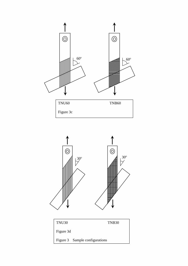
60° 60°
30° 30°
TNU60 TNB60 Figure 3c
TNU30 TNB30 Figure 3d Figure 3 Sample configurations

Figure 4a. Typical loading arrangement
Figure 4b. Detail of clamping arrangement to the upper timber sample in figure 4a
67 mm diameter steel shear-plate
connector
17 mm thick steel
M20 bolt Gr. 8.8.
24 mm diameter steel tie rod Steel box frame with
pinned arms Sample
Steel frame
Hydraulic jack and load cell
17 mm thick steel side plates connected
to base plate Strong floor
Detail of connector in figure 4b

Figure 5 Loading procedures in accordance with BS EN 26891.
Load / Displacement for 1TPU00-O
0
5
10
15
20
25
30
35
40
0 0.2 0.4 0.6 0.8 1 1.2Displacement (mm)
Load
(kN
)
Figure 6. Typical load-displacement graph

Figure 7. Failure of TPU00 sample by delamination on both sides.

Average Failure Loads
0
5
10
15
20
25
30
35
40
TPU00 test TPU10 test TPB00 test TPB30 test
Load
(kN
)
Figure 8 Average failure loads for all load parallel to the grain tension tests. The length of the error bars is one standard deviation
Average Stiffness
010
2030
4050
6070
8090
100
TPU00 test TPU10 test TPB00 test TPB30 test
Stiff
ness
(kN/
mm
)
Figure 9 Average stiffness for all load parallel to the grain tension tests. The length of the error bars is one standard deviation
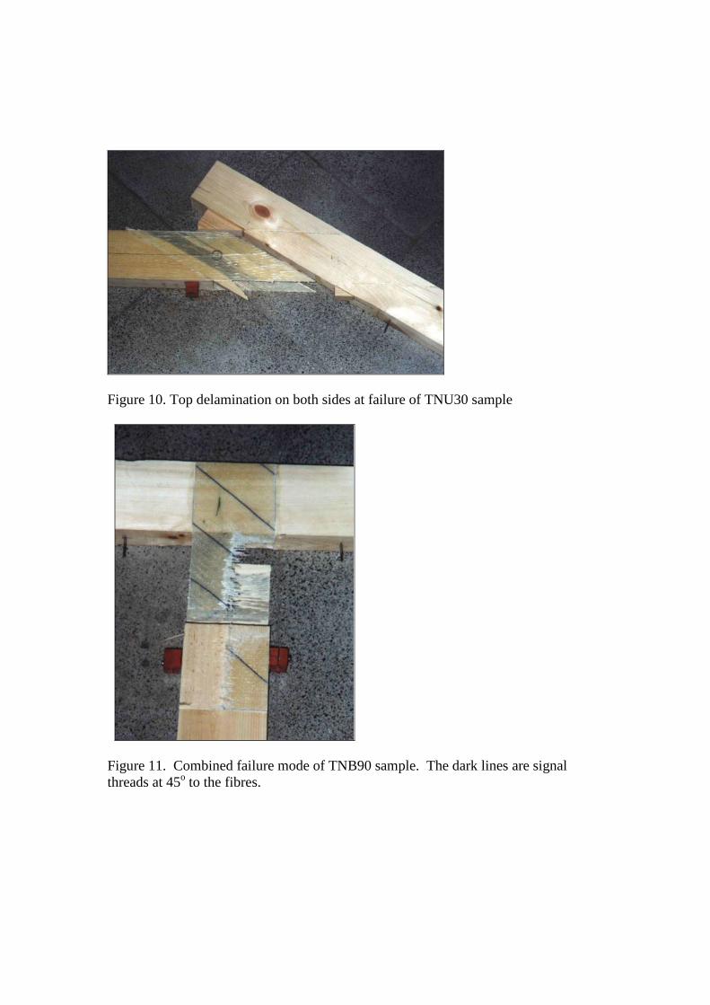
Figure 10. Top delamination on both sides at failure of TNU30 sample
Figure 11. Combined failure mode of TNB90 sample. The dark lines are signal threads at 45o to the fibres.
Average Failure Loads
0
5
10
15
20
25
30
35
40
TNU90test
TNU60test
TNU30test
TNB90test
TNB60test
TNB30test
Load
(kN
)
Figure 12 Average failure loads for all tension tests with the load not parallel to the grain. The length of the error bars is one standard deviation
Average Stiffness
0
10
20
30
40
50
60
70
TNU90test
TNU60test
TNU30test
TNB90test
TNB60test
TNB30test
Stiff
ness
(kN
/mm
)
Figure 13 Average stiffness for all tension tests with the load not parallel to the grain. The length of the error bars is one standard deviation