
JMV_LabGuide_Volume1
324
1194 North Mathilda Avenue Sunnyvale, CA 94089 USA 408-745-2000 www.juniper.net Worldwide Education Services Worldwide Education Services Junos MPLS and VPNs 12.a Detailed Lab Guide—Volume Course Number: EDU-JUN-JMV INTERNAL USE ONLY
Transcript of JMV_LabGuide_Volume1

1194 North Mathilda AvenueSunnyvale, CA 94089USA408-745-2000www.juniper.net
Worldwide Education ServicesWorldwide Education Services
Junos MPLS and VPNs12.a
Detailed Lab Guide—Volume 1
Course Number: EDU-JUN-JMV
INTERNAL U
SE ONLY

This document is produced by Juniper Networks, Inc.
This document or any part thereof may not be reproduced or transmitted in any form under penalty of law, without the prior written permission of Juniper Networks Education Services.
Juniper Networks, Junos, Steel-Belted Radius, NetScreen, and ScreenOS are registered trademarks of Juniper Networks, Inc. in the United States and other countries. The Juniper Networks Logo, the Junos logo, and JunosE are trademarks of Juniper Networks, Inc. All other trademarks, service marks, registered trademarks, or registered service marks are the property of their respective owners.
Juniper Networks reserves the right to change, modify, transfer, or otherwise revise this publication without notice.
YEAR 2000 NOTICE
Juniper Networks hardware and software products do not suffer from Year 2000 problems and hence are Year 2000 compliant. The Junos operating system has no known time-related limitations through the year 2038. However, the NTP application is known to have some difficulty in the year 2036.
SOFTWARE LICENSE
The terms and conditions for using Juniper Networks software are described in the software license provided with the software, or to the extent applicable, in an agreement executed between you and Juniper Networks, or Juniper Networks agent. By using Juniper Networks software, you indicate that you understand and agree to be bound by its license terms and conditions. Generally speaking, the software license restricts the manner in which you are permitted to use the Juniper Networks software, may contain prohibitions against certain uses, and may state conditions under which the license is automatically terminated. You should consult the software license for further details.
Junos MPLS and VPNs Detailed Lab Guide, Revision 12.a
Copyright © 2013 Juniper Networks, Inc. All rights reserved.
Printed in USA.
Revision History:
Revision 10.a—December 2010
Revision 12.a—June 2013
The information in this document is current as of the date listed above.
The information in this document has been carefully verified and is believed to be accurate for software Release 12.3R2.5. Juniper Networks assumes no responsibilities for any inaccuracies that may appear in this document. In no event will Juniper Networks be liable for direct, indirect, special, exemplary, incidental, or consequential damages resulting from any defect or omission in this document, even if advised of the possibility of such damages.
INTERNAL U
SE ONLY

Contents • iii
Contents
Lab 1: MPLS Fundamentals (Detailed) . . . . . . . . . . . . . . . . . . . . . . . . . . . . . . . . . . . . . . . 1-1Part 1: Configuring Network Interfaces and Baseline Protocols . . . . . . . . . . . . . . . . . . . . . . . . . . . 1-2Part 2: Configuring Customer Edge Router and Network Interfaces . . . . . . . . . . . . . . . . . . . . . . .1-11Part 3: Configuring a Static LSP Through the Core . . . . . . . . . . . . . . . . . . . . . . . . . . . . . . . . . . . . .1-19
Lab 2: Label Distribution Protocols (Detailed) . . . . . . . . . . . . . . . . . . . . . . . . . . . . . . . . . 2-1Part 1: Configuring Customer Edge Router and Network Interfaces . . . . . . . . . . . . . . . . . . . . . . . . 2-2Part 2: Configuring RSVP . . . . . . . . . . . . . . . . . . . . . . . . . . . . . . . . . . . . . . . . . . . . . . . . . . . . . . . . .2-10Part 3: Configuring a Explicit Route Object (ERO) . . . . . . . . . . . . . . . . . . . . . . . . . . . . . . . . . . . . . .2-16Part 4: Configuring LDP . . . . . . . . . . . . . . . . . . . . . . . . . . . . . . . . . . . . . . . . . . . . . . . . . . . . . . . . . . .2-19Part 5: Changing the Default Route Preference . . . . . . . . . . . . . . . . . . . . . . . . . . . . . . . . . . . . . . .2-22
Lab 3: CSPF (Detailed) . . . . . . . . . . . . . . . . . . . . . . . . . . . . . . . . . . . . . . . . . . . . . . . . . . . . 3-1Part 1: Creating the Baseline Network . . . . . . . . . . . . . . . . . . . . . . . . . . . . . . . . . . . . . . . . . . . . . . . 3-2Part 2: Enabling the TED . . . . . . . . . . . . . . . . . . . . . . . . . . . . . . . . . . . . . . . . . . . . . . . . . . . . . . . . . . . 3-7Part 3: Configuring RSVP-Signaled LSPs . . . . . . . . . . . . . . . . . . . . . . . . . . . . . . . . . . . . . . . . . . . . .3-12Part 4: Adding Administrative Groups to Core-Facing Interfaces . . . . . . . . . . . . . . . . . . . . . . . . . .3-15Part 5: Configuring LSPs to Take Gold, Silver, and Bronze Paths Using CSPF . . . . . . . . . . . . . . .3-18
Lab 4: Traffic Protection (Detailed) . . . . . . . . . . . . . . . . . . . . . . . . . . . . . . . . . . . . . . . . . . 4-1Part 1: Creating the Baseline Network . . . . . . . . . . . . . . . . . . . . . . . . . . . . . . . . . . . . . . . . . . . . . . . 4-2Part 2: Redistributing Routes into BGP . . . . . . . . . . . . . . . . . . . . . . . . . . . . . . . . . . . . . . . . . . . . . . . 4-5Part 3: Creating an LSP to the Remote PE . . . . . . . . . . . . . . . . . . . . . . . . . . . . . . . . . . . . . . . . . . . . 4-8Part 4: Configuring a Secondary Path for Added Protection . . . . . . . . . . . . . . . . . . . . . . . . . . . . .4-11Part 5: Configuring Secondary Standby Protection . . . . . . . . . . . . . . . . . . . . . . . . . . . . . . . . . . . . .4-15Part 6: Examining a Secondary/Secondary Protected LSP . . . . . . . . . . . . . . . . . . . . . . . . . . . . . .4-23Part 7: Examining a Fast-Reroute Protected LSP . . . . . . . . . . . . . . . . . . . . . . . . . . . . . . . . . . . . . .4-28Part 8: Examining Link and Node-Link Protected RSVP LSPs . . . . . . . . . . . . . . . . . . . . . . . . . . . .4-32Part 9: Configuring LDP Link Protection . . . . . . . . . . . . . . . . . . . . . . . . . . . . . . . . . . . . . . . . . . . . .4-37
Lab 5: Fate Sharing (Detailed) . . . . . . . . . . . . . . . . . . . . . . . . . . . . . . . . . . . . . . . . . . . . . . 5-1Part 1: Creating the Baseline Network . . . . . . . . . . . . . . . . . . . . . . . . . . . . . . . . . . . . . . . . . . . . . . . 5-2Part 2: Creating an LSP to the Remote PE . . . . . . . . . . . . . . . . . . . . . . . . . . . . . . . . . . . . . . . . . . . . 5-6Part 3: Configuring Fate Sharing . . . . . . . . . . . . . . . . . . . . . . . . . . . . . . . . . . . . . . . . . . . . . . . . . . .5-11Part 4: Configuring SRLGs . . . . . . . . . . . . . . . . . . . . . . . . . . . . . . . . . . . . . . . . . . . . . . . . . . . . . . . .5-14Part 5: Configuring Extended Admin Groups . . . . . . . . . . . . . . . . . . . . . . . . . . . . . . . . . . . . . . . . . .5-19
Lab 6: Miscellaneous MPLS Features (Detailed) . . . . . . . . . . . . . . . . . . . . . . . . . . . . . . . 6-1Part 1: Configuring the Baseline Network . . . . . . . . . . . . . . . . . . . . . . . . . . . . . . . . . . . . . . . . . . . . . 6-2Part 2: Configuring a RSVP LSP to Install a Route in the inet.0 Table . . . . . . . . . . . . . . . . . . . . 6-7Part 3: Configuring MPLS Traffic Engineering to Install an inet.0 Route . . . . . . . . . . . . . . . . .6-11Part 4: Using Policy to Control LSP Selection . . . . . . . . . . . . . . . . . . . . . . . . . . . . . . . . . . . . . . . . .6-14Part 5: Using LSP Metric to Control LSP Selection . . . . . . . . . . . . . . . . . . . . . . . . . . . . . . . . . . . . .6-22Part 6: Configuring Your Router to Not Decrement the TTL . . . . . . . . . . . . . . . . . . . . . . . . . . . . . .6-25Part 7: Configuring Your Router to Signal Explicit Null . . . . . . . . . . . . . . . . . . . . . . . . . . . . . . . . . .6-27Part 8: Configuring Your Router to Automatically Adjust the RSVP Reservation Based on Observed
Bandwidth . . . . . . . . . . . . . . . . . . . . . . . . . . . . . . . . . . . . . . . . . . . . . . . . . . . . . . . . . . . . . . .6-28Part 9: Using MPLS Ping to Verify LSP Connectivity . . . . . . . . . . . . . . . . . . . . . . . . . . . . . . . . . . . .6-30
INTERNAL U
SE ONLY

iv • Contents
Lab 7: L3VPN Static and BGP Routing (Detailed) . . . . . . . . . . . . . . . . . . . . . . . . . . . . . . . 7-1Part 1: Creating the Baseline SP Network and Enabling PE for Layer 3 VPN Signaling . . . . . . . . .7-2Part 2: Establishing an RSVP Signaled LSP Between PE Routers . . . . . . . . . . . . . . . . . . . . . . . . 7-10Part 3: Verify CE Router Configuration . . . . . . . . . . . . . . . . . . . . . . . . . . . . . . . . . . . . . . . . . . . . . . 7-12Part 4: Configuring the PE to CE Interface . . . . . . . . . . . . . . . . . . . . . . . . . . . . . . . . . . . . . . . . . . . 7-14Part 5: Configuring a Layer 3 VPN Instance . . . . . . . . . . . . . . . . . . . . . . . . . . . . . . . . . . . . . . . . . . 7-15Part 6: Configuring Static Routing Between the PE and CE Routers . . . . . . . . . . . . . . . . . . . . . . 7-17Part 7: Configuring BGP Routing Between the PE and CE Routers . . . . . . . . . . . . . . . . . . . . . . . 7-23
Lab 8: Route Reflection and Internet Access (Detailed) . . . . . . . . . . . . . . . . . . . . . . . . . 8-1Part 1: Creating the Baseline SP Network and Enabling PE for Layer 3 VPN Signaling . . . . . . . . .8-2Part 2: Verifying CE Router Configuration . . . . . . . . . . . . . . . . . . . . . . . . . . . . . . . . . . . . . . . . . . . . . .8-9Part 3: Configuring the PE to CE Interfaces . . . . . . . . . . . . . . . . . . . . . . . . . . . . . . . . . . . . . . . . . . 8-14Part 4: Configuring Two Layer 3 VPN Instances . . . . . . . . . . . . . . . . . . . . . . . . . . . . . . . . . . . . . . 8-16Part 5: Configuring BGP Routing Between the PE and CE Routers . . . . . . . . . . . . . . . . . . . . . . . 8-19Part 6: Implementing Route Target Filtering . . . . . . . . . . . . . . . . . . . . . . . . . . . . . . . . . . . . . . . . . 8-31Part 7: Configuring Internet Access Using a Non-VRF Interface . . . . . . . . . . . . . . . . . . . . . . . . . . 8-37
Lab 9: GRE Tunnel Integration (Detailed) . . . . . . . . . . . . . . . . . . . . . . . . . . . . . . . . . . . . . 9-1Part 1: Creating the Baseline SP Network and Enabling PE for Layer 3 VPN Signaling . . . . . . . . .9-2Part 2: Verifying CE Router Configuration . . . . . . . . . . . . . . . . . . . . . . . . . . . . . . . . . . . . . . . . . . . . .9-9Part 3: Configuring the PE to CE Interface . . . . . . . . . . . . . . . . . . . . . . . . . . . . . . . . . . . . . . . . . . . 9-12Part 4: Configuring a Layer 3 VPN Instance . . . . . . . . . . . . . . . . . . . . . . . . . . . . . . . . . . . . . . . . . . 9-13Part 5: Configuring OSPF Routing Between the PE and CE Routers . . . . . . . . . . . . . . . . . . . . . . 9-15Part 6: Establishing a GRE Tunnel Between PE Routers . . . . . . . . . . . . . . . . . . . . . . . . . . . . . . . 9-20Part 7: Creating and Adding a Static Route to inet.3 . . . . . . . . . . . . . . . . . . . . . . . . . . . . . . . . .9-21Part 8: Redistributing BGP Routes into OSPF . . . . . . . . . . . . . . . . . . . . . . . . . . . . . . . . . . . . . . . . 9-26
INTERNAL U
SE ONLY

www.juniper.net Course Overview • v
Course Overview
This five-day course is designed to provide students with MPLS-based virtual private network (VPN) knowledge and configuration examples. The course includes an overview of MPLS concepts such as control and forwarding plane, RSVP Traffic Engineering, LDP, Layer 3 VPNs, BGP Layer 2 VPNs, LDP Layer 2 Circuits, and virtual private LAN service (VPLS). This course also covers Junos operating system-specific implementations of Layer 2 control instances and active interface for VPLS.
Through demonstrations and hands-on labs, students will gain experience in configuring and monitoring the Junos OS and in device operations. This course uses Juniper Networks MX Series 3D Universal Edge Routers for the hands-on component, but the lab environment does not preclude the course from being applicable to other Juniper hardware platforms running the Junos OS. This course is based on the Junos OS Release 12.3R2.5.
Objectives
After successfully completing this course, you should be able to:
• Explain common terms relating to MPLS.
• Explain routers and the way they forward MPLS packets.
• Explain packet flow and handling through a label-switched path (LSP).
• Describe the configuration and verification of MPLS forwarding.
• Understand the information in the Label Information Base.
• Explain the two label distribution protocols used by the Junos OS.
• Configure and troubleshoot RSVP-signaled and LDP-signaled LSPs.
• Explain the constraints of both RSVP and LDP.
• Explain the path selection process of RSVP without the use of the Constrained Shortest Path First (CSPF) algorithm.
• Explain the Interior Gateway Protocol (IGP) extensions used to build the Traffic Engineering Database (TED).
• Describe the CSPF algorithm and its path selection process.
• Describe administrative groups and how they can be used to influence path selection.
• Explain the behavior of inter-area traffic engineered LSPs
• Describe the default traffic protection behavior of RSVP-Signaled LSPs.
• Explain the use of primary and secondary LSPs.
• Explain LSP priority and preemption.
• Describe the operation and configuration of fast reroute.
• Describe the operation and configuration of link and node protection.
• Describe the LSP optimization options.
• Describe the behavior of fate sharing.
• Describe how SRLG changes the CSPF algorithm when computing the path of a secondary LSP.
• Explain how extended admin groups can be used to influence path selection.
• Explain the purpose of several miscellaneous MPLS features.
• Explain the definition of the term “Virtual Private Network”.
• Describe the differences between provider-provisioned and customer-provisioned VPNs.
INTERNAL U
SE ONLY

vi • Course Overview www.juniper.net
• Describe the differences between Layer 2 VPNs and Layer 3 VPNs.
• Explain the features of provider-provisioned VPNs supported by the Junos OS.
• Explain the roles of Provider (P) routers, Provider Edge (PE) routers, and Customer Edge (CE) routers.
• Describe the VPN-IPv4 address formats.
• Describe the route distinguisher use and formats.
• Explain the RFC 4364 control flow.
• Create a routing instance, assign interfaces, create routes, and import and export routes within the routing instance using route distinguishers and route targets.
• Explain the purpose of BGP extended communities and how to configure and use these communities.
• Describe the steps necessary for proper operation of a PE to CE dynamic routing protocol.
• Configure a simple Layer 3 VPN using a dynamic CE-PE routing protocol.
• Describe the routing-instance switch.
• Explain the issues with the support of traffic originating on multi-access VPN routing and forwarding table (VRF table) interfaces.
• Use operational commands to view Layer 3 VPN control exchanges.
• Use operational commands to display Layer 3 VPN VRF tables.
• Monitor and troubleshoot PE-CE routing protocols.
• Describe the four ways to improve Layer 3 VPN scaling.
• Describe the three methods for providing Layer 3 VPN customers with Internet access.
• Describe how the auto-export command and routing table groups can be used to support communications between sites attached to a common PE router.
• Describe the flow of control and data traffic in a hub-and-spoke topology.
• Describe the various Layer 3 VPN class-of-service (CoS) mechanisms supported by the Junos OS.
• Explain the Junos OS support for generic routing encapsulation (GRE) and IP Security (IPsec) tunnels in Layer 3 VPNs.
• Describe the purpose and features of a BGP Layer 2 VPN.
• Describe the roles of a CE device, PE router, and P router in a BGP Layer 2 VPN.
• Explain the flow of control traffic and data traffic for a BGP Layer 2 VPN.
• Configure a BGP Layer 2 VPN and describe the benefits and requirements of over-provisioning.
• Monitor and troubleshoot a BGP Layer 2 VPN.
• Explain the BGP Layer 2 VPN scaling mechanisms and route reflection.
• Describe the Junos OS BGP Layer 2 VPN CoS support.
• Describe the flow of control and data traffic for an LDP Layer 2 circuit.
• Configure an LDP Layer 2 circuit.
• Monitor and troubleshoot an LDP Layer 2 circuit.
• Describe and configure circuit cross-connect (CCC) MPLS interface tunneling.
• Describe the difference between Layer 2 MPLS VPNs and VPLS.
• Explain the purpose of the PE device, the CE device, and the P device.
INTERNAL U
SE ONLY

www.juniper.net Course Overview • vii
• Explain the provisioning of CE and PE routers.
• Describe the signaling process of VPLS.
• Describe the learning and forwarding process of VPLS.
• Describe the potential loops in a VPLS environment.
• Configure BGP and LDP VPLS.
• Troubleshoot VPLS.
• Describe the Junos OS support for carrier of carriers.
• Describe the Junos OS support for interprovider VPNs.
Intended Audience
This course benefits individuals responsible for configuring and monitoring devices running the Junos OS.
Course Level
Junos MPLS and VPNs (JMV) is an advanced-level course.
Prerequisites
Students should have intermediate-level networking knowledge and an understanding of the Open Systems Interconnection (OSI) model and the TCP/IP protocol suite. Students should also attend the Introduction to the Junos Operating System (IJOS), Junos Routing Essentials (JRE), and Junos Service Provider Switching (JSPX) courses prior to attending this class.
INTERNAL U
SE ONLY

viii • Course Agenda www.juniper.net
Course Agenda
Day 1
Chapter 1: Course Introduction
Chapter 2: MPLS Fundamentals
MPLS Fundamentals Lab
Chapter 3: Label Distribution Protocols
Label Distribution Protocols Lab
Chapter 4: Constrained Shortest Path First
CSPF Lab
Day 2
Chapter 5: Traffic Protection and LSP Optimization
Traffic Protection Lab
Chapter 6: Fate Sharing
Fate Sharing Lab
Chapter 7: Miscellaneous MPLS Features
Miscellaneous MPLS Features Lab
Chapter 8: VPN Review
Chapter 9: Layer 3 VPNs
Day 3
Chapter 10: Basic Layer 3 VPN Configuration
Layer 3 VPN with Static and BGP Routing Lab
Chapter 11: Troubleshooting Layer 3 VPNs
Chapter 12: Layer 3 VPN Scaling and Internet Access
Route Reflection and Internet Access Lab
Chapter 13: Layer 3 VPNs—Advanced Topics
GRE Tunnel Integration Lab
Day 4
Chapter 14: BGP Layer 2 VPNs
BGP Layer 2 VPNs Lab
Chapter 15: Layer 2 VPN Scaling and CoS
Chapter 16: LDP Layer 2 Circuits
Circuit Cross-Connect and LDP Layer 2 Circuits Lab
Chapter 17: Virtual Private LAN ServiceIN
TERNAL USE O
NLY

www.juniper.net Course Agenda • ix
Day 5
Chapter 18: VPLS Configuration
VPLS Lab
Chapter 19: Interprovider VPNs
Carrier-of-Carriers VPNs Lab
Appendix A: Multicast VPNs
MVPN Lab
INTERNAL U
SE ONLY

x • Document Conventions www.juniper.net
Document Conventions
CLI and GUI Text
Frequently throughout this course, we refer to text that appears in a command-line interface (CLI) or a graphical user interface (GUI). To make the language of these documents easier to read, we distinguish GUI and CLI text from chapter text according to the following table.
Input Text Versus Output Text
You will also frequently see cases where you must enter input text yourself. Often these instances will be shown in the context of where you must enter them. We use bold style to distinguish text that is input versus text that is simply displayed.
Defined and Undefined Syntax Variables
Finally, this course distinguishes between regular text and syntax variables, and it also distinguishes between syntax variables where the value is already assigned (defined variables) and syntax variables where you must assign the value (undefined variables). Note that these styles can be combined with the input style as well.
Style Description Usage Example
Franklin Gothic Normal text. Most of what you read in the Lab Guide and Student Guide.
Courier New Console text:
• Screen captures
• Noncommand-related syntax
GUI text elements:
• Menu names
• Text field entry
commit complete
Exiting configuration mode
Select File > Open, and then click Configuration.conf in the Filename text box.
Style Description Usage Example
Normal CLI
Normal GUI
No distinguishing variant. Physical interface:fxp0, Enabled
View configuration history by clicking Configuration > History.
CLI Input
GUI Input
Text that you must enter. lab@San_Jose> show route
Select File > Save, and type config.ini in the Filename field.
Style Description Usage Example
CLI Variable
GUI Variable
Text where variable value is already assigned.
policy my-peers
Click my-peers in the dialog.
CLI Undefined
GUI Undefined
Text where the variable’s value is the user’s discretion and text where the variable’s value as shown in the lab guide might differ from the value the user must input.
Type set policy policy-name.
ping 10.0.x.y
Select File > Save, and type filename in the Filename field.
INTERNAL U
SE ONLY

www.juniper.net Additional Information • xi
Additional Information
Education Services Offerings
You can obtain information on the latest Education Services offerings, course dates, and class locations from the World Wide Web by pointing your Web browser to: http://www.juniper.net/training/education/.
About This Publication
The Junos MPLS and VPNs Detailed Lab Guide was developed and tested using software Release 12.3R2.5. Previous and later versions of software might behave differently so you should always consult the documentation and release notes for the version of code you are running before reporting errors.
This document is written and maintained by the Juniper Networks Education Services development team. Please send questions and suggestions for improvement to [email protected].
Technical Publications
You can print technical manuals and release notes directly from the Internet in a variety of formats:
• Go to http://www.juniper.net/techpubs/.
• Locate the specific software or hardware release and title you need, and choose the format in which you want to view or print the document.
Documentation sets and CDs are available through your local Juniper Networks sales office or account representative.
Juniper Networks Support
For technical support, contact Juniper Networks at http://www.juniper.net/customers/support/, or at 1-888-314-JTAC (within the United States) or 408-745-2121 (from outside the United States).
INTERNAL U
SE ONLY

xii • Additional Information www.juniper.net
INTERNAL U
SE ONLY

www.juniper.net MPLS Fundamentals (Detailed) • Lab 1–1
LabMPLS Fundamentals (Detailed)
Overview
This lab demonstrates configuration and monitoring of multiprotocol label switched path (MPLS) static label switched path (LSP) features on devices running the Junos operating system. In this lab, you use the command-line interface (CLI) to configure and monitor network interfaces, Open Shortest Path First (OSPF), Border Gateway Protocol (BGP), Virtual Routers and static MPLS LSPs.
The lab is available in two formats: a high-level format designed to make you think through each step and a detailed format that offers step-by-step instructions complete with sample output from most commands.
By completing this lab, you will perform the following tasks:
• Configure and verify proper operation of network interfaces.
• Configure and verify OSPF, BGP, and a virtual router.
• Configure and monitor a MPLS static LSP.
INTERNAL U
SE ONLY

Junos MPLS and VPNs
Lab 1–2 • MPLS Fundamentals (Detailed) www.juniper.net
Part 1: Configuring Network Interfaces and Baseline Protocols
In this lab part, you will be using the lab diagram for part 1. You will configure network interfaces on your assigned device. You will then verify that the interfaces are operational and that the system adds the corresponding routing table entries for the configured interfaces. After verifying your interfaces, you will configure the router to participate in the OSPF area 0.0.0.0. Once you have completed this, you will set up a internal BGP (IBGP) peering with the remote team’s router.
Step 1.1
Ensure that you know to which device you are assigned. Check with your instructor if necessary.
Step 1.2
Consult the management network diagram, provided by your instructor, to determine your device’s management address.
Question: What is the management address assigned to your station?
Answer: The answer varies. The sample hostname and IP address used in the output examples in this lab are for mxA-1, which uses 10.210.15.1 as its management IP address. The actual management subnet varies between delivery environments.
Note
The instructor will tell you the nature of your access and will provide you with the necessary details to access your assigned device.
INTERNAL U
SE ONLY

Junos MPLS and VPNs
www.juniper.net MPLS Fundamentals (Detailed) • Lab 1–3
Step 1.3
Access the CLI at your station using either the console, Telnet, or Secure Shell (SSH) as directed by your instructor. The following example shows simple Telnet access to mxA-1 using the Secure CRT program.
Step 1.4
Log in as user lab with the password supplied by your instructor. Enter configuration mode and load the reset configuration file jmv/lab1-start.config and commit.
mxA-1 (ttyp0)
login: labPassword:
--- JUNOS 12.3R2.5 built 2013-03-22 17:12:14 UTClab@mxA-1> configure Entering configuration mode
[edit]lab@mxB-1# load override jmv/lab1-start.config load complete
[edit]lab@mxB-1# commit commit complete
[edit]lab@mxB-1#
Step 1.5
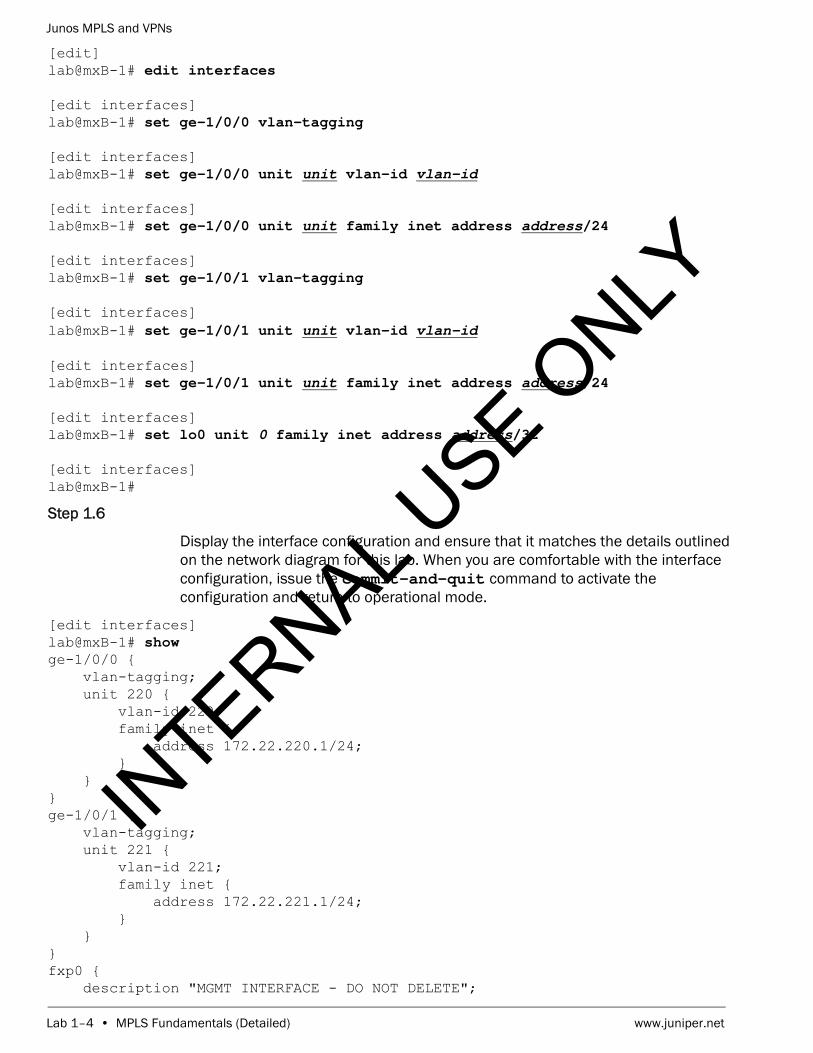
Navigate to the [edit interfaces] hierarchy level. Refer to the network diagram and configure the interfaces for your assigned device. Use the virtual local area network (VLAN) ID as the logical unit value for the tagged interface. Use logical unit 0 for all other interfaces. Remember to configure the loopback interface!
INTERNAL U
SE ONLY
Junos MPLS and VPNs
Lab 1–4 • MPLS Fundamentals (Detailed) www.juniper.net
[edit]lab@mxB-1# edit interfaces
[edit interfaces]lab@mxB-1# set ge-1/0/0 vlan-tagging
[edit interfaces]lab@mxB-1# set ge-1/0/0 unit unit vlan-id vlan-id
[edit interfaces]lab@mxB-1# set ge-1/0/0 unit unit family inet address address/24
[edit interfaces]lab@mxB-1# set ge-1/0/1 vlan-tagging
[edit interfaces]lab@mxB-1# set ge-1/0/1 unit unit vlan-id vlan-id
[edit interfaces]lab@mxB-1# set ge-1/0/1 unit unit family inet address address/24
[edit interfaces]lab@mxB-1# set lo0 unit 0 family inet address address/32
[edit interfaces]lab@mxB-1#
Step 1.6
Display the interface configuration and ensure that it matches the details outlined on the network diagram for this lab. When you are comfortable with the interface configuration, issue the commit-and-quit command to activate the configuration and return to operational mode.
[edit interfaces]lab@mxB-1# show ge-1/0/0 { vlan-tagging; unit 220 { vlan-id 220; family inet { address 172.22.220.1/24; } }}ge-1/0/1 { vlan-tagging; unit 221 { vlan-id 221; family inet { address 172.22.221.1/24; } }}fxp0 { description "MGMT INTERFACE - DO NOT DELETE";
INTERNAL U
SE ONLY

Junos MPLS and VPNs
www.juniper.net MPLS Fundamentals (Detailed) • Lab 1–5
unit 0 { family inet { address 10.210.15.3/27; } }}lo0 { unit 0 { family inet { address 193.168.2.1/32; } }}
[edit interfaces]lab@mxB-1# commit and-quit commit completeExiting configuration mode
lab@mxB-1>
Step 1.7
Issue the show interfaces terse command to verify the current state of the recently configured interfaces.
lab@mxB-1> show interfaces terse Interface Admin Link Proto Local Remotelc-0/0/0 up uplc-0/0/0.32769 up up vpls pfe-0/0/0 up uppfe-0/0/0.16383 up up inet inet6 pfh-0/0/0 up uppfh-0/0/0.16383 up up inet xe-0/0/0 up upxe-0/0/1 up downxe-0/0/2 up downxe-0/0/3 up downge-1/0/0 up upge-1/0/0.220 up up inet 172.22.220.1/24 multiservicege-1/0/0.32767 up up multiservicege-1/0/1 up upge-1/0/1.221 up up inet 172.22.221.1/24 multiservicege-1/0/1.32767 up up multiservicege-1/0/2 up up ge-1/0/3 up upge-1/0/4 up upge-1/0/5 up upge-1/0/6 up upge-1/0/7 up upge-1/0/8 up upge-1/0/9 up upge-1/1/0 up up
INTERNAL U
SE ONLY

Junos MPLS and VPNs
Lab 1–6 • MPLS Fundamentals (Detailed) www.juniper.net
ge-1/1/1 up downge-1/1/2 up upge-1/1/3 up upge-1/1/4 up upge-1/1/5 up upge-1/1/6 up upge-1/1/7 up upge-1/1/8 up upge-1/1/9 up upcbp0 up updemux0 up updsc up up em0 up upem0.0 up up inet 10.0.0.4/8 128.0.0.1/2 128.0.0.4/2 inet6 fe80::200:ff:fe00:4/64 fec0::a:0:0:4/64 tnp 0x4 em1 up downfxp0 up upfxp0.0 up up inet 10.210.15.3/27 gre up upipip up upirb up uplo0 up uplo0.0 up up inet 193.168.2.1 --> 0/0lo0.16384 up up inet 127.0.0.1 --> 0/0lo0.16385 up up inet lsi up upme0 up upme0.0 up up mtun up uppimd up uppime up uppip0 up uppp0 up uptap up up
Question: What are the Admin and Link states for the recently configured interfaces?
Answer: The configured interfaces should all show Admin and Link states of up, as shown in the previous output. If the configured interfaces are in the down state, contact your instructor.
Step 1.8
Issue the show route command to view the current route entries.
INTERNAL U
SE ONLY

Junos MPLS and VPNs
www.juniper.net MPLS Fundamentals (Detailed) • Lab 1–7
lab@mxB-1> show route
inet.0: 7 destinations, 7 routes (7 active, 0 holddown, 0 hidden)+ = Active Route, - = Last Active, * = Both
10.210.15.0/27 *[Direct/0] 21:24:43 > via fxp0.010.210.15.3/32 *[Local/0] 21:24:43 Local via fxp0.0172.22.220.0/24 *[Direct/0] 00:02:20 > via ge-1/0/0.220172.22.220.1/32 *[Local/0] 00:02:20 Local via ge-1/0/0.220172.22.221.0/24 *[Direct/0] 00:02:20 > via ge-1/0/1.221172.22.221.1/32 *[Local/0] 00:02:20 Local via ge-1/0/1.221193.168.2.1/32 *[Direct/0] 00:02:20 > via lo0.0
Question: Does the routing table display an entry for all local interface addresses and directly connected networks?
Answer: The answer should be yes. If necessary, you can refer back to the network diagram and compare it with the displayed route entries.
Question: Are any routes currently hidden?
Answer: You can possibly see hidden routes depending on the environment and how the delivery rack was prepared. In this example, no hidden routes are present as indicated in the summary line towards the top of the sample output.
Step 1.9
Enter in to configuration mode and navigate to the [edit protocols ospf] hierarchy level. Configure the core facing interfaces in area 0.0.0.0. Remember to add the loopback interface.
lab@mxB-1> configure Entering configuration mode
[edit]lab@mxB-1# edit protocols ospf
[edit protocols ospf]lab@mxB-1# set area 0 interface ge-1/0/0.unit
INTERNAL U
SE ONLY

Junos MPLS and VPNs
Lab 1–8 • MPLS Fundamentals (Detailed) www.juniper.net
[edit protocols ospf]lab@mxB-1# set area 0 interface ge-1/0/1.unit
[edit protocols ospf]lab@mxB-1# set area 0 interface lo0
[edit protocols ospf]lab@mxB-1#
Step 1.10
Activate the configuration changes and exit to operational mode. Issue the show ospf neighbor command.
[edit protocols ospf]lab@mxB-1# commit and-quit commit completeExiting configuration mode
lab@mxB-1> show ospf neighbor Address Interface State ID Pri Dead172.22.220.2 ge-1/0/0.220 Full 193.168.5.1 128 34172.22.221.2 ge-1/0/1.221 Full 193.168.5.4 128 35
Question: Which neighbor state is shown for the listed interfaces?
Answer: The neighbor state for the ge-1/0/0 and ge-1/0/1 interfaces should be Full, as shown in the previous sample output. If you do not see the Full state for both interfaces, check your configuration.
Step 1.11
Using the ping utility, verify reachability to remote team’s interfaces. Remember to verify the loopback address.
lab@mxB-1> ping address rapid count 10 PING 172.22.222.1 (172.22.222.1): 56 data bytes!!!!!!!!!!--- 172.22.222.1 ping statistics ---10 packets transmitted, 10 packets received, 0% packet lossround-trip min/avg/max/stddev = 0.524/0.716/1.372/0.303 ms
Note
Before proceeding, ensure that the remote student team in your pod finishes the previous steps.
INTERNAL U
SE ONLY

Junos MPLS and VPNs
www.juniper.net MPLS Fundamentals (Detailed) • Lab 1–9
lab@mxB-1> ping address rapid count 10 PING 172.22.223.1 (172.22.223.1): 56 data bytes!!!!!!!!!!--- 172.22.223.1 ping statistics ---10 packets transmitted, 10 packets received, 0% packet lossround-trip min/avg/max/stddev = 0.528/0.576/0.872/0.100 ms
lab@mxB-1> ping address rapid count 10 PING 193.168.2.2 (193.168.2.2): 56 data bytes!!!!!!!!!!--- 193.168.2.2 ping statistics ---10 packets transmitted, 10 packets received, 0% packet lossround-trip min/avg/max/stddev = 0.523/0.572/0.882/0.104 ms
Question: Are the ping tests successful?
Answer: Yes, the ping tests should be successful at this time. If your tests are not successful, check with the remote student team or your instructor.
Step 1.12
Enter configuration mode and define the autonomous system number designated for your network. Refer to the network diagram as necessary.
lab@mxB-1> configure Entering configuration mode
[edit]lab@mxB-1# set routing-options autonomous-system 65512
Step 1.13
Navigate to the [edit protocols bgp] hierarchy level. Configure a BGP group named my-int-group that establishes an internal BGP peering session with the remote team’s PE router. Refer to the network diagram for this lab as necessary.
[edit]lab@mxB-1# edit protocols bgp
[edit protocols bgp]lab@mxB-1# set group my-int-group type internal
[edit protocols bgp]lab@mxB-1# set group my-int-group local-address local-loopback-address
[edit protocols bgp]lab@mxB-1# set group my-int-group neighbor remote-loopback-address
[edit protocols bgp]lab@mxB-1# commitcommit complete
INTERNAL U
SE ONLY

Junos MPLS and VPNs
Lab 1–10 • MPLS Fundamentals (Detailed) www.juniper.net
[edit protocols bgp]lab@mxB-1#
Step 1.14
Issue the run show bgp summary command to view the current BGP summary information for your device.
[edit protocols bgp]lab@mxB-1# run show bgp summary Groups: 1 Peers: 1 Down peers: 0Table Tot Paths Act Paths Suppressed History Damp State Pendinginet.0 0 0 0 0 0 0Peer AS InPkt OutPkt OutQ Flaps Last Up/Dwn State|#Active/Received/Accepted/Damped...193.168.2.2 65512 2 3 0 0 2 0/0/0/0 0/0/0/0
Question: How many BGP neighbors does your router currently list?
Answer: Your router should list the one IBGP peer you defined previously in this lab part. If you do not see the IBGP peer, check your configuration. If necessary, consult with the remote team and the instructor.
Question: Does your session show an Active state?
Answer: You should not see an Active state on this peering. If you see this, check your configuration and consult with the remote team and the instructor.
STOP Do not proceed until the remote team finishes Part 1.IN
TERNAL USE O
NLY

Junos MPLS and VPNs
www.juniper.net MPLS Fundamentals (Detailed) • Lab 1–11
Part 2: Configuring Customer Edge Router and Network Interfaces
In this lab part, you will reference the lab diagram for parts 2 and 3. You will configure a virtual router instance on your router, representing the customer edge (CE) router. You will configure the interfaces and networks needed to establish a external BGP (EBGP) peering between the customer edge router and your provider edge (PE) router. You will first configure your virtual router and all interfaces for both routers. Second you will configure the EBGP peering session between the two routers. Next you will advertise your loopback address from your CE device to your PE router. You will share these routes with your IBGP peer.
Step 2.1
Refer to the lab diagram to ensure you navigate to the correct virtual router name. Navigate to the [edit routing-instances instance-name] hierarchy and configure the instance to behave as a virtual router. Configure the interfaces that should be members of the virtual router. Make sure you include a loopback interface.
[edit protocols bgp]lab@mxB-1# top edit routing-instances instance-name
[edit routing-instances ceB-1]lab@mxB-1# set instance-type virtual-router
[edit routing-instances ceB-1]lab@mxB-1# set interface ge-1/1/4
[edit routing-instances ceB-1]lab@mxB-1# set interface lo0.1
Step 2.2
Review the virtual router configuration up to this point by issuing the command show.
[edit routing-instances ceB-1]lab@mxB-1# show instance-type virtual-router;interface ge-1/1/4.0; ## 'ge-1/1/4.0' is not definedinterface lo0.1; ## 'lo0.1' is not defined
Question: Do you see any issues with the current configuration?
Answer: You should notice that the interfaces that have been added to the virtual router need to be defined in the main instance.
INTERNAL U
SE ONLY

Junos MPLS and VPNs
Lab 1–12 • MPLS Fundamentals (Detailed) www.juniper.net
Step 2.3
Navigate to the [edit interfaces] hierarchy. Configure both physical interfaces required for the connection to the virtual router. Configure unit 1 under the loopback interface. Consult the network diagram for proper IP addressing. After verifying your configuration, commit and exit to operational mode to verify connectivity.
[edit routing-instances ceB-1]lab@mxB-1# top edit interfaces
[edit interfaces]lab@mxB-1# set ge-1/0/4 unit 0 family inet address address/24
[edit interfaces]lab@mxB-1# set ge-1/1/4 unit 0 family inet address address/24
[edit interfaces]lab@mxB-1# set lo0 unit 1 family inet address address
[edit interfaces]lab@mxB-1# commit and-quit commit completeExiting configuration mode
lab@mxB-1>
Step 2.4
Verify connectivity from your CE router to your PE router using the ping utility.
lab@mxB-1> ping address routing-instance instance-name count 1 PING 10.0.20.1 (10.0.20.1): 56 data bytes64 bytes from 10.0.20.1: icmp_seq=0 ttl=64 time=2.006 ms
--- 10.0.20.1 ping statistics ---1 packets transmitted, 1 packets received, 0% packet lossround-trip min/avg/max/stddev = 2.006/2.006/2.006/0.000 ms
Step 2.5
Return to configuration mode and configure the main instance (PE) to establish an EBGP peering session, named my-ext-group, to your virtual router (CE). Verify configuration looks correct before moving on. Please refer to the network diagram for appropriate peer autonomous system numbers.
lab@mxB-1> configure Entering configuration mode
[edit]lab@mxB-1# edit protocols bgp
Note
Use Ctrl + c to stop a continuous ping operation.
INTERNAL U
SE ONLY

Junos MPLS and VPNs
www.juniper.net MPLS Fundamentals (Detailed) • Lab 1–13
[edit protocols bgp]lab@mxB-1# set group my-ext-group type external
[edit protocols bgp]lab@mxB-1# set group my-ext-group peer-as peer-as
[edit protocols bgp]lab@mxB-1# set group my-ext-group neighbor address
[edit protocols bgp]lab@mxB-1# show group my-ext-group type external;peer-as 65201;neighbor 10.0.20.2;
Question: Do you have to configure the group type as external?
Answer: No, the default group type for bgp is external. However, it is good practice to specify the type to ensure other people reviewing the configuration can differentiate between internal and external groups.
Step 2.6
Navigate to the [edit routing-instances instance-name] hierarchy and configure the autonomous system for the virtual router (CE). Next configure the EBGP group named my-ext-group, on the CE router. Once you are satisfied with the configuration commit and verify that the neighbor relationship is established before moving on to the next step.
[edit protocols bgp]lab@mxB-1# top edit routing-instances instance-name
[edit routing-instances ceB-1]lab@mxB-1# set routing-options autonomous-system as-number
[edit routing-instances ceB-1]lab@mxB-1# edit protocols bgp
[edit routing-instances ceB-1 protocols bgp]lab@mxB-1# set group my-ext-group type external
[edit routing-instances ceB-1 protocols bgp]lab@mxB-1# set group my-ext-group peer-as 65512
[edit routing-instances ceB-1 protocols bgp]lab@mxB-1# set group my-ext-group neighbor address
[edit routing-instances ceB-1 protocols bgp]
INTERNAL U
SE ONLY

Junos MPLS and VPNs
Lab 1–14 • MPLS Fundamentals (Detailed) www.juniper.net
lab@mxB-1# commitcommit complete
[edit routing-instances ceB-1 protocols bgp]lab@mxB-1# run show bgp summary Groups: 3 Peers: 3 Down peers: 0Table Tot Paths Act Paths Suppressed History Damp State Pendinginet.0 1 1 0 0 0 0Peer AS InPkt OutPkt OutQ Flaps Last Up/Dwn State|#Active/Received/Accepted/Damped...10.0.20.1 65512 8 7 0 0 2:12 Establ ceB-1.inet.0: 1/1/1/010.0.20.2 65201 6 8 0 0 2:12 Establ inet.0: 0/0/0/0193.168.2.2 65512 84 83 0 0 36:23 Establ inet.0: 1/1/1/0
Question: Is your EBGP peering established between your PE and CE routers?
Answer: Yes, you should see two new peerings for the recently configured EBGP. One should display as a normal peering (PE instance) and the other peering from the virtual router (CE) should display as a routing instance peering, identified by instance-name.inet.0, followed by the route information.
Question: Are you sending any routes from your CE router?
Answer: No, at this time there should not be any routes being sent from the CE router.
Step 2.7
Navigate to the [edit policy-options] hierarchy and configure a policy named ce-export-loopback. Allow your CE router’s loopback address to be exported. After creating the policy, navigate to the virtual router and apply this new policy as an export policy to your EBGP group. Commit and exit to operational mode after you are satisfied with your configuration.
[edit routing-instances ceB-1 protocols bgp]lab@mxB-1# top edit policy-options
[edit policy-options]lab@mxB-1# set policy-statement ce-export-loopback term 1 from protocol direct
INTERNAL U
SE ONLY

Junos MPLS and VPNs
www.juniper.net MPLS Fundamentals (Detailed) • Lab 1–15
[edit policy-options]lab@mxB-1# set policy-statement ce-export-loopback term 1 from route-filter ce-loopback-address exact
[edit policy-options]lab@mxB-1# set policy-statement ce-export-loopback term 1 then accept
[edit policy-options]lab@mxB-1# top edit routing-instances instance-name
[edit routing-instances ceB-1]lab@mxB-1# set protocols bgp group my-ext-group export ce-export-loopback
[edit routing-instances ceB-1]lab@mxB-1# commit and-quit commit completeExiting configuration mode
lab@mxB-1>
Step 2.8
Verify that you are advertising the loopback address to your EBGP peer. Next verify you are advertising the EBGP route from your PE router to your IBGP peer.
lab@mxB-1> show route advertising-protocol bgp local-pe-ge-1/0/4-address
ceB-1.inet.0: 4 destinations, 4 routes (4 active, 0 holddown, 0 hidden) Prefix Nexthop MED Lclpref AS path* 193.168.12.1/32 Self I
lab@mxB-1> show route advertising-protocol bgp remote-pe-loopback-address
inet.0: 37 destinations, 37 routes (37 active, 0 holddown, 0 hidden) Prefix Nexthop MED Lclpref AS path* 193.168.12.1/32 10.0.20.2 100 65201 I
Step 2.9
Verify that you are receiving the remote CE loopback from your IBGP neighbor. The total destination routes may differ in your outputs.
lab@mxB-1> show route receive-protocol bgp remote-pe-loopback-address
inet.0: 37 destinations, 37 routes (36 active, 0 holddown, 1 hidden)
Note
Before proceeding, ensure that the remote student team in your pod finishes the previous steps.IN
TERNAL USE O
NLY

Junos MPLS and VPNs
Lab 1–16 • MPLS Fundamentals (Detailed) www.juniper.net
ceB-1.inet.0: 3 destinations, 3 routes (3 active, 0 holddown, 0 hidden)
lab@mxB-1>
Question: Where is the route the remote peer is advertising to us?
Answer: It is being received but is stored as a hidden route, which indicates you might have a problem.
Step 2.10
Take an extensive look at the hidden route and determine why the route is hidden.
lab@mxB-1> show route hidden extensive
inet.0: 37 destinations, 37 routes (36 active, 0 holddown, 1 hidden)193.168.12.2/32 (1 entry, 0 announced) BGP Preference: 170/-101 Next hop type: Unusable Address: 0x24cf8a8 Next-hop reference count: 1 State: <Hidden Int Ext> Local AS: 65512 Peer AS: 65512 Age: 1:09 Validation State: unverified Task: BGP_65512.193.168.2.2+52758 AS path: 65202 I Accepted Localpref: 100 Router ID: 193.168.2.2 Indirect next hops: 1 Protocol next hop: 10.0.21.2 Indirect next hop: 0 - INH Session ID: 0x0
Question: Why is the protocol (BGP) next hop for the route? Which router in the topology owns that address?
Answer: The answer will vary by team. In the example the protocol next hop is 10.0.21.2. This address is owned by the remote CE.
INTERNAL U
SE ONLY
Junos MPLS and VPNs
www.juniper.net MPLS Fundamentals (Detailed) • Lab 1–17
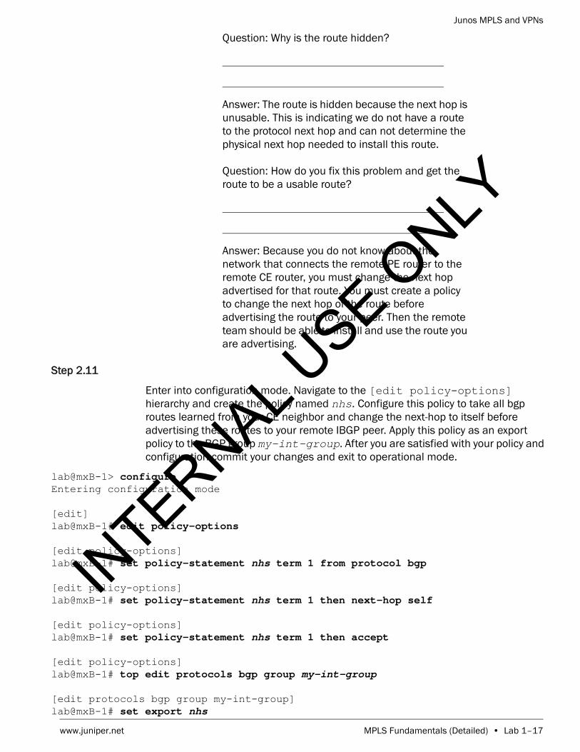
Question: Why is the route hidden?
Answer: The route is hidden because the next hop is unusable. This is indicating we do not have a route to the protocol next hop and can not determine the physical next hop needed to install this route.
Question: How do you fix this problem and get the route to be a usable route?
Answer: Because you do not know about the network that connects the remote PE router to the remote CE router, you must change the next hop advertised for that route. You must create a policy to change the next hop of the route before advertising the route to your peer. Then the remote team should be able to install and use the route you are advertising.
Step 2.11
Enter into configuration mode. Navigate to the [edit policy-options] hierarchy and create the policy named nhs. Configure this policy to take all bgp routes learned from your CE neighbor and change the next-hop to itself before advertising these routes to your remote IBGP peer. Apply this policy as an export policy to the BGP group my-int-group. After you are satisfied with your policy and configuration commit your changes and exit to operational mode.
lab@mxB-1> configure Entering configuration mode
[edit]lab@mxB-1# edit policy-options
[edit policy-options]lab@mxB-1# set policy-statement nhs term 1 from protocol bgp
[edit policy-options]lab@mxB-1# set policy-statement nhs term 1 then next-hop self
[edit policy-options]lab@mxB-1# set policy-statement nhs term 1 then accept
[edit policy-options]lab@mxB-1# top edit protocols bgp group my-int-group
[edit protocols bgp group my-int-group]lab@mxB-1# set export nhs
INTERNAL U
SE ONLY

Junos MPLS and VPNs
Lab 1–18 • MPLS Fundamentals (Detailed) www.juniper.net
[edit protocols bgp group my-int-group]lab@mxB-1# commit and-quit commit completeExiting configuration mode
lab@mxB-1>
Step 2.12
Verify that the route to the remote CE router’s loopback address is now usable and installed in the routing table.
lab@mxB-1> show route receive-protocol bgp remote-pe-loopback-address
inet.0: 37 destinations, 37 routes (37 active, 0 holddown, 0 hidden) Prefix Nexthop MED Lclpref AS path* 193.168.12.2/32 193.168.2.2 100 65202 I
ceB-1.inet.0: 4 destinations, 4 routes (4 active, 0 holddown, 0 hidden)
Question: Do you see the route now?
Answer: Yes, you should now see the route for the remote CE loopback. If you do not see this route please review your configuration and consult with the remote team to verify correct configuration. If necessary, please consult the instructor.
Step 2.13
Verify that you are receiving and installing the route to the remote CE router in your virtual router.
lab@mxB-1> show route receive-protocol bgp local-pe-ge-1/0/4-address
inet.0: 37 destinations, 37 routes (37 active, 0 holddown, 0 hidden)
ceB-1.inet.0: 4 destinations, 4 routes (4 active, 0 holddown, 0 hidden) Prefix Nexthop MED Lclpref AS path* 193.168.12.2/32 10.0.20.1 65512 65202 I
lab@mxB-1> show route table instance-name.inet.0
ceB-1.inet.0: 4 destinations, 4 routes (4 active, 0 holddown, 0 hidden)+ = Active Route, - = Last Active, * = Both
Note
Before proceeding, ensure that the remote student team in your pod finishes the previous steps.
INTERNAL U
SE ONLY

Junos MPLS and VPNs
www.juniper.net MPLS Fundamentals (Detailed) • Lab 1–19
10.0.20.0/24 *[Direct/0] 00:40:43 > via ge-1/1/4.010.0.20.2/32 *[Local/0] 00:40:43 Local via ge-1/1/4.0193.168.12.1/32 *[Direct/0] 00:40:43 > via lo0.1193.168.12.2/32 *[BGP/170] 00:03:14, localpref 100 AS path: 65512 65202 I, validation-state: unverified > to 10.0.20.1 via ge-1/1/4.0
Question: Is the route present in your CE routing table?
Answer: Yes, you should now see the route in your routing instance table.
STOP Do not proceed until the remote team finishes Part 2.
Part 3: Configuring a Static LSP Through the Core
In this lab part, you will reference the lab diagram for parts 2 and 3. You will configure a static LSP that will be used for traffic that is destined to the network connected to the remote PE router. After configuring the LSP we will verify CE to CE router communication through the static LSP.
Step 3.1
Enter into configuration mode and navigate to the [edit interfaces] hierarchy. Configure the core facing interface to allow MPLS traffic.
lab@mxB-1> configure Entering configuration mode
[edit]lab@mxB-1# edit interfaces
[edit interfaces]lab@mxB-1# set ge-1/0/0 unit unit family mpls
[edit interfaces]lab@mxB-1#
Step 3.2
Navigate to [edit protocols mpls] hierarchy and add the interface all statement. As good practice please be sure to disable the management interface.
INTERNAL U
SE ONLY

Junos MPLS and VPNs
Lab 1–20 • MPLS Fundamentals (Detailed) www.juniper.net
[edit interfaces]lab@mxB-1# top edit protocols mpls
[edit protocols mpls]lab@mxB-1# set interface all
[edit protocols mpls]lab@mxB-1# set interface fxp0 disable
[edit protocols mpls]lab@mxB-1#
Step 3.3
Commit the configuration changes. Issue the run show route table mpls.0 command to verify that the MPLS table has been created.
[edit protocols mpls]lab@mxB-1# commit commit complete
[edit protocols mpls]lab@mxB-1# run show route table mpls.0
mpls.0: 4 destinations, 4 routes (4 active, 0 holddown, 0 hidden)+ = Active Route, - = Last Active, * = Both
0 *[MPLS/0] 00:00:06, metric 1 Receive1 *[MPLS/0] 00:00:06, metric 1 Receive2 *[MPLS/0] 00:00:06, metric 1 Receive13 *[MPLS/0] 00:00:06, metric 1 Receive
Question: What are the routes that you see?
Answer: You should see the four labels that are automatically created. Packets received with these label values are sent to the Routing Engine for processing. Label 0 is the IPv4 explicit null label, Label 1 is the MPLS equivalent of the IP Router Alert label, Label 2 is the IPv6 explicit null label, and Label 13 is the GAL indicator.
Step 3.4
Review the interfaces that are participating in MPLS to ensure that we have the proper configuration by executing the run show mpls interface command.
[edit protocols mpls]lab@mxB-1# run show mpls interface
INTERNAL U
SE ONLY

Junos MPLS and VPNs
www.juniper.net MPLS Fundamentals (Detailed) • Lab 1–21
Interface State Administrative groups (x: extended)ge-1/0/0.220 Up <none>
Question: What interface do you see?
Answer: You should see the interface you configured family mpls under. If you see something other than this interface, please review your configuration and contact your instructor.
Step 3.5
Create a static LSP named my-static-lsp with the egress address of the remote PE loopback.
[edit protocols mpls]lab@mxB-1# set static-label-switched-path my-static-lsp ingress to remote-pe-loopback-address
Step 3.6
Navigate to the [edit protocols mpls static-label-switched-path my-static-lsp ingress] hierarchy. Configure the next-hop for the LSP and assign the appropriate label to the LSP. Please consult the lab diagram for the path and label to be assigned. Review your configuration and after you are satisfied with the configuration, commit the changes and exit to operational mode.
[edit protocols mpls]lab@mxB-1# edit static-label-switched-path my-static-lsp ingress
[edit protocols mpls static-label-switched-path my-static-lsp ingress]lab@mxB-1# set next-hop next-hop-address
[edit protocols mpls static-label-switched-path my-static-lsp ingress]lab@mxB-1# set push label
[edit protocols mpls static-label-switched-path my-static-lsp ingress]lab@mxB-1# show next-hop 172.22.220.2;to 193.168.2.2;push 1000201;
[edit protocols mpls static-label-switched-path my-static-lsp ingress]lab@mxB-1# commit and-quit commit completeExiting configuration mode
lab@mxB-1>
Step 3.7
Issue the show mpls static-lsp ingress command to view the current status of the recently configured LSP.
INTERNAL U
SE ONLY

Junos MPLS and VPNs
Lab 1–22 • MPLS Fundamentals (Detailed) www.juniper.net
lab@mxB-1> show mpls static-lsp ingress Ingress LSPs:LSPname To Statemy-static-lsp 193.168.2.2 UpTotal 1, displayed 1, Up 1, Down 0
Question: What is the state of the static LSP?
Answer: The state of the static LSP should be Up.
Step 3.8
Review the route being used for the remote CE router’s loopback by issuing the show route remote-ce-loopback-address command.
lab@mxB-1> show route remote-ce-loopback-address
inet.0: 37 destinations, 37 routes (37 active, 0 holddown, 0 hidden)+ = Active Route, - = Last Active, * = Both
193.168.12.2/32 *[BGP/170] 00:19:47, localpref 100, from 193.168.2.2 AS path: 65202 I, validation-state: unverified > to 172.22.220.2 via ge-1/0/0.220, Push 1000201
ceB-1.inet.0: 4 destinations, 4 routes (4 active, 0 holddown, 0 hidden)+ = Active Route, - = Last Active, * = Both
193.168.12.2/32 *[BGP/170] 00:19:47, localpref 100 AS path: 65512 65202 I, validation-state: unverified > to 10.0.20.1 via ge-1/1/4.0
Question: How do you determine that the static LSP is going to be used when directing traffic to this destination?
Answer: Careful review of the route installed in the inet.0 table shows that there is a label value of 1000201 that will be pushed into the packet. This indicates that the packet will be sent with a label into the MPLS LSP and will be forwarded by the next-hop router based on this label.
Step 3.9
Look at the traffic statistics for traffic traversing our new LSP. Execute the show mpls static-lsp statistics ingress command to view the statistics for the traffic the enters the LSP at this router.
INTERNAL U
SE ONLY

Junos MPLS and VPNs
www.juniper.net MPLS Fundamentals (Detailed) • Lab 1–23
lab@mxB-1> show mpls static-lsp statistics ingressIngress LSPs:LSPname To State Packets Bytesmy-static-lsp 193.168.2.2 Up 0 0Total 1, displayed 1, Up 1, Down 0
Step 3.10
Test the LSP by using the ping utility from the virtual router by executing the ping remote-ce-loopback source local-ce-loopback count 10 rapid routing-instance instance-name command.
lab@mxB-1> ping remote-ce-loopback source local-ce-loopback count 10 rapid routing-instance instance-namePING 193.168.12.2 (193.168.12.2): 56 data bytes!!!!!!!!!!--- 193.168.12.2 ping statistics ---10 packets transmitted, 10 packets received, 0% packet lossround-trip min/avg/max/stddev = 0.562/0.596/0.838/0.081 ms
Step 3.11
Look at the LSP statistics to verify that the traffic traversed the LSP.
lab@mxB-1> show mpls static-lsp statistics ingress Ingress LSPs:LSPname To State Packets Bytesmy-static-lsp 193.168.2.2 Up 10 840Total 1, displayed 1, Up 1, Down 0
Question: How many packets do you see that traversed through the LSP?
Answer: You should see that 10 packets have traversed through the LSP. These are the 10 ping packets that were just sent to the remote CE. If the remote team in your pod has also completed this task you will see 20 ping packets.
Step 3.12
Log out of your assigned device using the exit command.
lab@mxB-1> exit
mxB-1 (ttyu0)
login:
STOP Tell your instructor that you have completed this lab.
INTERNAL U
SE ONLY

Junos MPLS and VPNs
Lab 1–24 • MPLS Fundamentals (Detailed) www.juniper.net
INTERNAL U
SE ONLY

Junos MPLS and VPNs
www.juniper.net MPLS Fundamentals (Detailed) • Lab 1–25
INTERNAL U
SE ONLY

Junos MPLS and VPNs
Lab 1–26 • MPLS Fundamentals (Detailed) www.juniper.net
INTERNAL U
SE ONLY

Junos MPLS and VPNs
www.juniper.net MPLS Fundamentals (Detailed) • Lab 1–27
INTERNAL U
SE ONLY

Junos MPLS and VPNs
Lab 1–28 • MPLS Fundamentals (Detailed) www.juniper.net
INTERNAL U
SE ONLY

www.juniper.net Label Distribution Protocols (Detailed) • Lab 2–1
LabLabel Distribution Protocols (Detailed)
Overview
This lab demonstrates configuration and monitoring of Resource Reservation Protocol (RSVP) and Label Distribution (LDP) signaled label switched path (LSP) features on routers running the Junos operating system. In this lab, you use the command-line interface (CLI) to configure and monitor network interfaces, Border Gateway Protocol (BGP), Virtual Routers, RSVP LSPs, and LDP LSPs.
The lab is available in two formats: a high-level format designed to make you think through each step and a detailed format that offers step-by-step instructions complete with sample output from most commands.
By completing this lab, you will perform the following tasks:
• Configure and verify proper operation of network interfaces.
• Configure and verify BGP, and a virtual router.
• Configure and monitor a RSVP LSP.
• Modify RSVP LSP by explicitly defining path requirements.
• Configure and monitor a LDP LSP.
• Manipulate the default behavior of RSVP and LDP, depending on network requirements.
INTERNAL U
SE ONLY

Junos MPLS and VPNs
Lab 2–2 • Label Distribution Protocols (Detailed) www.juniper.net
Part 1: Configuring Customer Edge Router and Network Interfaces
In this lab part, you will configure the virtual router representing the customer edge (CE) router. You will load a configuration that will automatically configure the interfaces and networks needed to establish an external BGP (EBGP) peering between your customer edge router and your provider edge (PE) router. The loaded configuration will configure your virtual router and all interfaces for both routers and also configure the EBGP peering session between the two routers. You will then configure your CE router to advertise the loopback address from your CE device to your PE router. Your PE router will share these routes with your internal BGP (IBGP) peer.
Step 1.1
Ensure that you know to which device you are assigned. Check with your instructor if necessary.
Step 1.2
Consult the management network diagram, provided by your instructor, to determine your device’s management address.
Question: What is the management address assigned to your station?
Answer: The answer varies. The sample hostname and IP address used in the output examples in this lab are for mxB-1, which uses 10.210.15.1 as its management IP address. The actual management subnet varies between delivery environments.
Note
The instructor will tell you the nature of your access and will provide you with the necessary details to access your assigned device.
INTERNAL U
SE ONLY

Junos MPLS and VPNs
www.juniper.net Label Distribution Protocols (Detailed) • Lab 2–3
Step 1.3
Access the CLI at your station using either the console, Telnet, or Secure Shell (SSH) as directed by your instructor. The following example shows simple Telnet access to mxB-1 using the Secure CRT program.
Step 1.4
Log in as user lab with the password supplied by your instructor. Enter configuration mode and load the reset configuration file jmv/lab2-start.config and commit.
mxB-1 (ttyp0)
login: labPassword:
--- JUNOS 12.3R2.5 built 2013-03-22 17:12:14 UTClab@mxB-1> configure Entering configuration mode
[edit]lab@mxB-1# load override jmv/lab2-start.config load complete
[edit]lab@mxB-1# commit commit complete
[edit]lab@mxB-1#
Step 1.5
Verify that your Open Shortest Path First (OSPF) neighbor relationships are up and operational.
[edit]lab@mxB-1# run show ospf neighbor
INTERNAL U
SE ONLY

Junos MPLS and VPNs
Lab 2–4 • Label Distribution Protocols (Detailed) www.juniper.net
Address Interface State ID Pri Dead172.22.220.2 ge-1/0/0.220 Full 193.168.5.1 128 32172.22.221.2 ge-1/0/1.221 Full 193.168.5.4 128 31
Question: What is the state of your PE router’s OSPF neighbors?
Answer: After a short time, the OSPF neighbors should attain the Full state.
Step 1.6
Verify connectivity from CE to PE router using the ping utility.
[edit]lab@mxB-1# run ping local-pe-address routing-instance instance-name count 1 PING 10.0.20.1 (10.0.20.1): 56 data bytes64 bytes from 10.0.20.1: icmp_seq=0 ttl=64 time=0.722 ms
--- 10.0.20.1 ping statistics ---1 packets transmitted, 1 packets received, 0% packet lossround-trip min/avg/max/stddev = 0.722/0.722/0.722/0.000 ms
Question: Was the attempt to ping successful?
Answer: The ping should be successful.
Step 1.7
Verify that the BGP neighbor relationship is established before moving on to the next step.
[edit]lab@mxB-1# run show bgp summary Groups: 3 Peers: 3 Down peers: 0Table Tot Paths Act Paths Suppressed History Damp State Pendinginet.0 0 0 0 0 0 0Peer AS InPkt OutPkt OutQ Flaps Last Up/Dwn State|#Active/Received/Accepted/Damped...10.0.20.1 65512 24 23 0 0 9:17 Establ ceB-1.inet.0: 0/0/0/010.0.20.2 65201 23 25 0 0 9:17 Establ inet.0: 0/0/0/0193.168.2.2 65512 24 23 0 0 9:22 Establ inet.0: 0/0/0/0
INTERNAL U
SE ONLY
Junos MPLS and VPNs
www.juniper.net Label Distribution Protocols (Detailed) • Lab 2–5
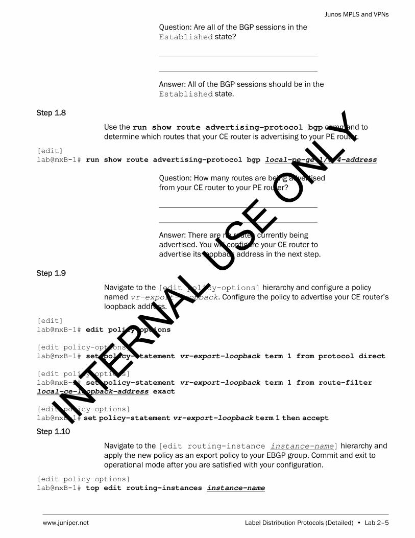
Question: Are all of the BGP sessions in the Established state?
Answer: All of the BGP sessions should be in the Established state.
Step 1.8
Use the run show route advertising-protocol bgp command to determine which routes that your CE router is advertising to your PE router.
[edit]lab@mxB-1# run show route advertising-protocol bgp local-pe-ge-1/0/4-address
Question: How many routes are being advertised from your CE router to your PE router?
Answer: There are no routes currently being advertised. You will configure your CE router to advertise its loopback address in the next step.
Step 1.9
Navigate to the [edit policy-options] hierarchy and configure a policy named vr-export-loopback. Configure the policy to advertise your CE router’s loopback address.
[edit]lab@mxB-1# edit policy-options
[edit policy-options]lab@mxB-1# set policy-statement vr-export-loopback term 1 from protocol direct
[edit policy-options]lab@mxB-1# set policy-statement vr-export-loopback term 1 from route-filter local-ce-loopback-address exact
[edit policy-options]lab@mxB-1# set policy-statement vr-export-loopback term 1 then accept
Step 1.10
Navigate to the [edit routing-instance instance-name] hierarchy and apply the new policy as an export policy to your EBGP group. Commit and exit to operational mode after you are satisfied with your configuration.
[edit policy-options]lab@mxB-1# top edit routing-instances instance-name
INTERNAL U
SE ONLY

Junos MPLS and VPNs
Lab 2–6 • Label Distribution Protocols (Detailed) www.juniper.net
[edit routing-instances ce1-1]lab@mxB-1# set protocols bgp group my-ext-group export vr-export-loopback
[edit routing-instances ce1-1]lab@mxB-1# commit and-quit commit completeExiting configuration mode
lab@mxB-1>
Step 1.11
Verify that you are advertising your CE router’s loopback address to your EBGP peer.
lab@mxB-1> show route advertising-protocol bgp local-pe-ge-1/0/4-address
ceB-1.inet.0: 4 destinations, 4 routes (4 active, 0 holddown, 0 hidden) Prefix Nexthop MED Lclpref AS path* 193.168.12.1/32 Self
Question: Are any routes being advertised from your CE router to your PE router?
Answer: The CE router is advertising a route that represents its loopback address.
Step 1.12
Verify the advertisement of the CE router’s loopback route from the local PE router to the remote IBGP peer.
lab@mxB-1> show route advertising-protocol bgp remote-pe-loopback-address
inet.0: 37 destinations, 37 routes (37 active, 0 holddown, 0 hidden) Prefix Nexthop MED Lclpref AS path* 193.168.12.1/32 10.0.20.2 100 65201 I
Question: What route is being advertised from your PE router to the remote PE router? Why is it being advertised?
Answer: The local PE router is advertising the local CE router’s loopback to the remote PE. The local PE is automatically advertising this route to its IBGP peers due to BGP’s default rules of route advertisement.
INTERNAL U
SE ONLY

Junos MPLS and VPNs
www.juniper.net Label Distribution Protocols (Detailed) • Lab 2–7
Step 1.13
Verify that the local PE is receiving the remote CE router’s loopback from the remote PE neighbor.
lab@mxB-1> show route receive-protocol bgp remote-pe-loopback-address
inet.0: 37 destinations, 37 routes (36 active, 0 holddown, 1 hidden)
ceB-1.inet.0: 3 destinations, 3 routes (3 active, 0 holddown, 0 hidden)
Question: Is the local PE router installing any routes from the remote PE into the routing table?
Answer: No routes from the remote PE are being installed in the routing tables.
Question: Do you notice anything interesting about the output of the command?
Answer: There are hidden routes being received but not installed in the routing table.
Step 1.14
Take an extensive look at the hidden route and determine why the route is hidden.
lab@mxB-1> show route hidden extensive
inet.0: 37 destinations, 37 routes (36 active, 0 holddown, 1 hidden)193.168.12.2/32 (1 entry, 0 announced) BGP Preference: 170/-101 Next hop type: Unusable Address: 0x24cf8a8 Next-hop reference count: 1 State: <Hidden Int Ext> Local AS: 65512 Peer AS: 65512 Age: 4:07 Validation State: unverified Task: BGP_65512.193.168.2.2+179 AS path: 65202 I Accepted
Note
Before proceeding, ensure that the remote student team in your pod finishes the previous steps.
INTERNAL U
SE ONLY

Junos MPLS and VPNs
Lab 2–8 • Label Distribution Protocols (Detailed) www.juniper.net
Localpref: 100 Router ID: 193.168.2.2 Indirect next hops: 1 Protocol next hop: 10.0.21.2 Indirect next hop: 0 - INH Session ID: 0x0
ceB-1.inet.0: 3 destinations, 3 routes (3 active, 0 holddown, 0 hidden)
Question: Why is the route hidden?
Answer: The route is hidden because the next hop is unusable. This is indicating we do not have a route to the protocol next hop and cannot determine the physical next hop needed to install this route.
Question: How do we fix this problem and get the route to be a usable route?
Answer: Because we do not know about the network that connects the remote PE router to the remote CE router, we must change the next hop advertised for that route. We must create a policy to change the next hop of the route before advertising the route to our peer. Then the remote team should be able to install and use the route we are advertising.
Step 1.15
Enter into configuration mode. Navigate to the [edit policy-options] hierarchy and create the policy named nhs. Configure this policy to take all BGP routes learned from your CE neighbor and change the next hop to itself before advertising these routes to your remote IBGP peer.
lab@mxB-1> configure Entering configuration mode
[edit]lab@mxB-1# edit policy-options
[edit policy-options]lab@mxB-1# set policy-statement nhs term 1 from protocol bgp
[edit policy-options]lab@mxB-1# set policy-statement nhs term 1 then next-hop self
[edit policy-options]lab@mxB-1# set policy-statement nhs term 1 then accept
INTERNAL U
SE ONLY

Junos MPLS and VPNs
www.juniper.net Label Distribution Protocols (Detailed) • Lab 2–9
Step 1.16
Apply the new policy as an export policy to the BGP group my-int-group. After you are satisfied with your policy and configuration commit your changes and exit to operational mode.
[edit policy-options]lab@mxB-1# top edit protocols bgp group my-int-group
[edit protocols bgp group my-int-group]lab@mxB-1# set export nhs
[edit protocols bgp group my-int-group]lab@mxB-1# commit and-quit commit completeExiting configuration mode
lab@mxB-1>
Step 1.17
Verify that the remote loopback address is now usable and installed in the routing table.
lab@mxB-1> show route receive-protocol bgp remote-pe-loopback-address
inet.0: 37 destinations, 37 routes (37 active, 0 holddown, 0 hidden) Prefix Nexthop MED Lclpref AS path* 193.168.12.2/32 193.168.2.2 100 65202 I
ceB-1.inet.0: 4 destinations, 4 routes (4 active, 0 holddown, 0 hidden)
Question: Do you see the route now?
Answer: Yes, you should now see the route for the remote CE loopback. If you do not see this route please review your configuration and consult with the remote team to verify correct configuration. If necessary, please consult the instructor.
Step 1.18
Verify you are receiving and installing the route to the remote CE router in your virtual router.
Note
Before proceeding, ensure that the remote student team in your pod finishes the previous steps.
INTERNAL U
SE ONLY

Junos MPLS and VPNs
Lab 2–10 • Label Distribution Protocols (Detailed) www.juniper.net
lab@mxB-1> show route remote-ce-loopback-address
inet.0: 37 destinations, 37 routes (37 active, 0 holddown, 0 hidden)+ = Active Route, - = Last Active, * = Both
193.168.12.2/32 *[BGP/170] 00:03:20, localpref 100, from 193.168.2.2 AS path: 65202 I, validation-state: unverified > to 172.22.220.2 via ge-1/0/0.220 to 172.22.221.2 via ge-1/0/1.221
ceB-1.inet.0: 4 destinations, 4 routes (4 active, 0 holddown, 0 hidden)+ = Active Route, - = Last Active, * = Both
193.168.12.2/32 *[BGP/170] 00:03:20, localpref 100 AS path: 65512 65202 I, validation-state: unverified > to 10.0.20.1 via ge-1/1/4.0
Question: Is the route present in your CE router’s routing table?
Answer: Yes, you should now see the route in your routing instance table.
STOP Do not proceed until the remote team finishes Part 1.
Part 2: Configuring RSVP
In this lab part, you will configure a RSVP signaled LSP that will be used for traffic that is destined to the network connected to the remote PE router. After configuring the LSP we will verify CE to CE router communication through the RSVP LSP.
Step 2.1
Enter into configuration mode and navigate to the [edit interfaces] hierarchy. Configure the core facing interfaces to allow multiprotocol label switching (MPLS) traffic.
lab@mxB-1> configure Entering configuration mode
[edit]lab@mxB-1# edit interfaces
[edit interfaces]lab@mxB-1# set ge-1/0/0 unit unit family mpls
[edit interfaces]lab@mxB-1# set ge-1/0/1 unit unit family mpls
INTERNAL U
SE ONLY

Junos MPLS and VPNs
www.juniper.net Label Distribution Protocols (Detailed) • Lab 2–11
Step 2.2
Navigate to [edit protocols mpls] hierarchy and add the interface all statement. As good practice please be sure to disable the management interface.
[edit interfaces]lab@mxB-1# top edit protocols mpls
[edit protocols mpls]lab@mxB-1# set interface all
[edit protocols mpls]lab@mxB-1# set interface fxp0 disable
Step 2.3
Commit the configuration changes and review the interfaces that are participating in MPLS to ensure we have the proper configuration by executing the run show mpls interface command.
[edit protocols mpls]lab@mxB-1# commit commit complete
[edit protocols mpls]lab@mxB-1# run show mpls interface Interface State Administrative groups (x: extended)ge-1/0/0.220 Up <none>ge-1/0/1.221 Up <none>
Step 2.4
Navigate to the [edit protocols rsvp] hierarchy. Add the appropriate core facing interfaces manually. Remember that you must specify the correct unit number when adding interfaces to any protocol configuration. The default Junos OS behavior is to assume unit 0 if no unit is specified. Review the configuration before committing to ensure the interfaces are correct.
[edit protocols mpls]lab@mxB-1# top edit protocols rsvp
[edit protocols rsvp]lab@mxB-1# set interface ge-1/0/0.unit
[edit protocols rsvp]lab@mxB-1# set interface ge-1/0/1.unit
[edit protocols rsvp]lab@mxB-1# show interface ge-1/0/0.220;interface ge-1/0/1.221;
[edit protocols rsvp]lab@mxB-1# commit commit complete
INTERNAL U
SE ONLY

Junos MPLS and VPNs
Lab 2–12 • Label Distribution Protocols (Detailed) www.juniper.net
Step 2.5
Add the configuration for creating the LSP. Navigate to the [edit protocols mpls] hierarchy. First, turn off constrained shortest path first (CSPF) by issuing the set no-cspf command. Next, create a label-switched-path named localPE-to-remotePE-pod. For example, if you are assigned router mxB-1, your peer router is mxB-2 and your pod is B. The LSP for mxB-1 should be named pe1-to-pe2-B. Your LSP should egress at your remote peer’s loopback address. Verify that the configuration looks correct. Commit and exit to operation mode when you are satisfied with the changes.
[edit protocols rsvp]lab@mxB-1# top edit protocols mpls
[edit protocols mpls]lab@mxB-1# set no-cspf
[edit protocols mpls]lab@mxB-1# set label-switched-path localPE-to-remotePE-pod to remote-PE-loopback-address
[edit protocols mpls]lab@mxB-1# show no-cspf;label-switched-path pe1-to-pe2-B { to 193.168.2.2;}interface all;interface fxp0.0 { disable;}
[edit protocols mpls]lab@mxB-1# commit and-quit commit completeExiting configuration mode
lab@mxB-1>
Step 2.6
Verify the status of your recently configured LSP reviewing the information displayed by issuing the show mpls lsp command.
Note
It is perfectly acceptable to use the interface all option when adding the interfaces into RSVP. For this lab, however, we ask that you explicitly identify the interfaces to demonstrate the importance of including the correct unit number when manually configuring particular interfaces.
INTERNAL U
SE ONLY

Junos MPLS and VPNs
www.juniper.net Label Distribution Protocols (Detailed) • Lab 2–13
lab@mxB-1> show mpls lsp Ingress LSP: 1 sessionsTo From State Rt P ActivePath LSPname193.168.2.2 193.168.2.1 Up 0 * pe1-to-pe2-BTotal 1 displayed, Up 1, Down 0
Egress LSP: 1 sessionsTo From State Rt Style Labelin Labelout LSPname 193.168.2.1 193.168.2.2 Up 0 1 FF 3 - pe2-to-pe1-2Total 1 displayed, Up 1, Down 0
Transit LSP: 0 sessionsTotal 0 displayed, Up 0, Down 0
Question: How many LSPs are reflected in the output and what are the terminating points?
Answer: If the remote team has finished configuring their LSP, you should see two LSPs. The LSP you configured should be displayed under the Ingress section and the other should be displayed under the Egress section. If the remote team has not finished their configuration you will only see the entry under the Ingress section. The terminating points of both LSP should be the loopback address of the ingress and egress routers.
Question: Can you tell what path the LSP signaled over?
Answer: No, from the basic output you cannot determine the path the LSP is using. To see what path the LSP is using you must include the detail or extensive tag on the command you used.
Step 2.7
Review the ingress LSP in more detail by including the ingress and extensive options with the previous command.
lab@mxB-1> show mpls lsp ingress extensive Ingress LSP: 1 sessions
193.168.2.2 From: 193.168.2.1, State: Up, ActiveRoute: 0, LSPname: pe1-to-pe2-B ActivePath: (primary) LSPtype: Static Configured, Penultimate hop popping LoadBalance: Random
INTERNAL U
SE ONLY

Junos MPLS and VPNs
Lab 2–14 • Label Distribution Protocols (Detailed) www.juniper.net
Encoding type: Packet, Switching type: Packet, GPID: IPv4 *Primary State: Up Priorities: 7 0 SmartOptimizeTimer: 180 Received RRO (ProtectionFlag 1=Available 2=InUse 4=B/W 8=Node 10=SoftPreempt 20=Node-ID): 172.22.220.2 172.22.201.2 172.22.206.2 172.22.222.1 4 May 9 18:30:18.819 Selected as active path 3 May 9 18:30:18.819 Record Route: 172.22.220.2 172.22.201.2 172.22.206.2 172.22.222.1 2 May 9 18:30:18.819 Up 1 May 9 18:30:18.757 Originate Call Created: Thu May 9 18:30:19 2013Total 1 displayed, Up 1, Down 0
Question: Can you determine what routers in the network are being traversed by the LSP you configured?
Answer: Yes. By comparing the hop addresses captured by the record route object (RRO) and the lab diagram you can determine the exact path the LSP is using.
Step 2.8
Verify traffic that is destined to the remote CE router’s loopback will use the LSP by issuing the show route remote-CE-loopback-address command.
lab@mxB-1> show route remote-CE-loopback-address
inet.0: 37 destinations, 37 routes (37 active, 0 holddown, 0 hidden)+ = Active Route, - = Last Active, * = Both
193.168.12.2/32 *[BGP/170] 00:57:52, localpref 100, from 193.168.2.2 AS path: 65202 I, validation-state: unverified > to 172.22.220.2 via ge-1/0/0.220, label-switched-path pe1-to-pe2-B
ceB-1.inet.0: 4 destinations, 4 routes (4 active, 0 holddown, 0 hidden)+ = Active Route, - = Last Active, * = Both
193.168.12.2/32 *[BGP/170] 00:57:52, localpref 100 AS path: 65512 65202 I, validation-state: unverified > to 10.0.20.1 via ge-1/1/4.0
INTERNAL U
SE ONLY

Junos MPLS and VPNs
www.juniper.net Label Distribution Protocols (Detailed) • Lab 2–15
Question: Will traffic destined for the remote CE get forwarded using the LSP?
Answer: The route to the remote CE router’s loopback address is associated with an LSP, therefore all packets destined to that address should be forwarded using the LSP.
Step 2.9
Verify the remote CE router’s loopback is reachable from your local CE router by sending five Internet Control Message Protocol (ICMP) packets. Make sure to source the ICMP packets from the local CE router’s loopback address.
lab@mxB-1> ping remote-ce-loopback-address source local-ce-loopback-address routing-instance instance-name count 5 PING 193.168.12.2 (193.168.12.2): 56 data bytes64 bytes from 193.168.12.2: icmp_seq=0 ttl=59 time=0.869 ms64 bytes from 193.168.12.2: icmp_seq=1 ttl=59 time=0.787 ms64 bytes from 193.168.12.2: icmp_seq=2 ttl=59 time=0.701 ms64 bytes from 193.168.12.2: icmp_seq=3 ttl=59 time=0.688 ms64 bytes from 193.168.12.2: icmp_seq=4 ttl=59 time=0.755 ms
--- 193.168.12.2 ping statistics ---5 packets transmitted, 5 packets received, 0% packet lossround-trip min/avg/max/stddev = 0.688/0.760/0.869/0.065 ms
Question: Were the pings successful?
Answer: All five pings should be successful.
Step 2.10
Verify the ICMP packets traversed the LSP by displaying the traffic statistics for the LSP.
lab@mxB-1> show mpls lsp statistics ingress Ingress LSP: 1 sessionsTo From State Packets Bytes LSPname193.168.2.2 193.168.2.1 Up 5 420 pe1-to-pe2-BTotal 1 displayed, Up 1, Down 0
INTERNAL U
SE ONLY

Junos MPLS and VPNs
Lab 2–16 • Label Distribution Protocols (Detailed) www.juniper.net
Question: How many packets have been forwarded over the LSP?
Answer: The example shows that five packets have been forwarded over the LSP. If the other team has also performed the ping test, you may see that 10 packets have traversed the LSP.
STOP Do not proceed until the remote team finishes Part 2.
Part 3: Configuring a Explicit Route Object (ERO)
In this lab part, you will create a path using both strict and loose path constraints. You will apply the path as the primary path to your existing LSP, forcing the LSP to signal along the specified path. You will decide which path the LSP will traverse. The only criteria for this task is that you must have at least one strict hop and one loose hop defined for the path. The example below is from the perspective of the local PE router. The path example will have a strict hop requirement of the p4 router and a loose hop requirement of the p3 router. This path was chosen for demonstration purposes only—you might choose to engineer your LSP path differently.
Step 3.1
Enter into configuration mode and edit to the [edit protocols mpls] hierarchy. Create a path named my-ER0 and configure the strict and loose hops you want the LSP path to signal along.
lab@mxB-1> configure Entering configuration mode
[edit]lab@mxB-1# edit protocols mpls
[edit protocols mpls]lab@mxB-1# set path my-ERO p4-address strict
[edit protocols mpls]lab@mxB-1# set path my-ERO p3-address loose
[edit protocols mpls]lab@mxB-1# show no-cspf;label-switched-path pe1-to-pe2-B { to 193.168.2.2;}path my-ERO { 172.22.221.2 strict;
INTERNAL U
SE ONLY

Junos MPLS and VPNs
www.juniper.net Label Distribution Protocols (Detailed) • Lab 2–17
193.168.5.3 loose;}interface all;interface fxp0.0 { disable;}
[edit protocols mpls]lab@mxB-1
Step 3.2
Apply the ERO you just created as the primary path used by the LSP you configured in Part 2. If you do not remember what the LSP name was, you can use the question mark option to display the LSPs that are configured on the router. Review the configuration changes before committing and exiting to operational mode.
[edit protocols mpls]lab@mxB-1# set label-switched-path ?Possible completions: <path_name> Name of path pe1-to-pe2-B Name of path
[edit protocols mpls]lab@mxB-1# set label-switched-path lsp-name primary my-ERO
[edit protocols mpls]lab@mxB-1# show no-cspf;label-switched-path pe1-to-pe2-B { to 193.168.2.2; primary my-ERO;}path my-ERO { 172.22.221.2 strict; 193.168.5.3 loose;}interface all;interface fxp0.0 { disable;}
[edit protocols mpls]lab@mxB-1# commit and-quit commit completeExiting configuration mode
lab@mxB-1>
Step 3.3
Verify the status of your LSP using the show mpls lsp ingress command.
lab@mxB-1> show mpls lsp ingress Ingress LSP: 1 sessions
INTERNAL U
SE ONLY

Junos MPLS and VPNs
Lab 2–18 • Label Distribution Protocols (Detailed) www.juniper.net
To From State Rt P ActivePath LSPname193.168.2.2 193.168.2.1 Up 0 * my-ERO pe1-to-pe2-BTotal 1 displayed, Up 1, Down 0
Question: What is the state of your LSP?
Answer: If your configuration is correct, the state of the LSP will show Up. If it does not, please review your configuration and correct any issues. Please ask the instructor for assistance if needed.
Question: What is the active path being used?
Answer: You should see the path name you configured as the primary path (my-ERO) displayed under the ActivePath column.
Step 3.4
Review the output displayed from the show mpls lsp ingress detail command to verify the LSP is following the path you created.
lab@mxB-1> show mpls lsp ingress detail Ingress LSP: 1 sessions
193.168.2.2 From: 193.168.2.1, State: Up, ActiveRoute: 0, LSPname: pe1-to-pe2-B ActivePath: my-ERO (primary) LSPtype: Static Configured, Penultimate hop popping LoadBalance: Random Encoding type: Packet, Switching type: Packet, GPID: IPv4 *Primary my-ERO State: Up Priorities: 7 0 SmartOptimizeTimer: 180 Received RRO (ProtectionFlag 1=Available 2=InUse 4=B/W 8=Node 10=SoftPreempt 20=Node-ID): 172.22.221.2 172.22.203.2 172.22.204.2 172.22.207.1 172.22.222.1Total 1 displayed, Up 1, Down 0IN
TERNAL USE O
NLY

Junos MPLS and VPNs
www.juniper.net Label Distribution Protocols (Detailed) • Lab 2–19
Question: Does the RRO reflect the path you specified?
Answer: The Record Route Object (RRO) should display the physical interfaces addresses along the path you specified.
Part 4: Configuring LDP
In this lab part, you will deactivate RSVP and add LDP to your network setup. Then you will verify that traffic will transit the network using the LDP LSP.
Step 4.1
Enter into configuration mode and deactivate RSVP. Commit the configuration change.
lab@mxB-1> configure Entering configuration mode
[edit]lab@mxB-1# deactivate protocols rsvp
[edit]lab@mxB-1# commit commit complete
Step 4.2
Navigate to the [edit protocols ldp] hierarchy and add the interface all statement. As good practice, remember to disable the management interface. After making the configuration changes commit and exit to operation mode for verification.
[edit]lab@mxB-1# edit protocols ldp
[edit protocols ldp]lab@mxB-1# set interface all
[edit protocols ldp]lab@mxB-1# set interface fxp0 disable
[edit protocols ldp]lab@mxB-1# commit and-quit commit completeExiting configuration mode
lab@mxB-1>
INTERNAL U
SE ONLY

Junos MPLS and VPNs
Lab 2–20 • Label Distribution Protocols (Detailed) www.juniper.net
Step 4.3
Verify the proper interfaces are participating in LDP by issuing the command show ldp interface.
lab@mxB-1> show ldp interface Interface Label space ID Nbr count Next hellolo0.0 193.168.2.1:0 0 0ge-1/0/0.220 193.168.2.1:0 1 2ge-1/0/1.221 193.168.2.1:0 1 1
Question: Do you see the correct interfaces?
Answer: You should see entries for lo0, ge-1/0/0, and ge-1/0/1 with your proper unit number. If you see something other than the expected interfaces please review your configuration and if necessary request assistance from the instructor.
Step 4.4
Verify the status of the LSP by issuing the show ldp session command.
lab@mxB-1> show ldp session Address State Connection Hold time Adv. Mode193.168.5.1 Operational Open 20 DU193.168.5.4 Operational Open 20 DU
Question: What is the status of the connection?
Answer: The connection should display as Open for each session.
Step 4.5
Verify traffic that is destined to the remote CE router’s loopback will use the LSP by issuing the show route remote-ce-loopback-address command.
lab@mxB-1> show route remote-ce-loopback-address
inet.0: 37 destinations, 37 routes (37 active, 0 holddown, 0 hidden)+ = Active Route, - = Last Active, * = Both
193.168.12.2/32 *[BGP/170] 20:40:01, localpref 100, from 193.168.2.2 AS path: 65202 I, validation-state: unverified > to 172.22.220.2 via ge-1/0/0.220, Push 300080 to 172.22.221.2 via ge-1/0/1.221, Push 300096
ceB-1.inet.0: 4 destinations, 4 routes (4 active, 0 holddown, 0 hidden)+ = Active Route, - = Last Active, * = Both
INTERNAL U
SE ONLY

Junos MPLS and VPNs
www.juniper.net Label Distribution Protocols (Detailed) • Lab 2–21
193.168.12.2/32 *[BGP/170] 20:40:01, localpref 100 AS path: 65512 65202 I, validation-state: unverified > to 10.0.20.1 via ge-1/1/4.0
Question: Will traffic destined for the remote CE get forwarded using an LSP?
Answer: The route to the remote CE router’s loopback address is associated with an MPLS label push operation, therefore all packets destined to that address should be forwarded using an LSP.
Step 4.6
Verify the remote CE router’s loopback is reachable from your local CE router by sending five ICMP packets.
lab@mxB-1> ping remote-ce-loopback-address source local-ce-loopback-address routing-instance instance-name count 5 PING 193.168.12.2 (193.168.12.2): 56 data bytes64 bytes from 193.168.12.2: icmp_seq=0 ttl=59 time=0.768 ms64 bytes from 193.168.12.2: icmp_seq=1 ttl=59 time=0.784 ms64 bytes from 193.168.12.2: icmp_seq=2 ttl=59 time=0.778 ms64 bytes from 193.168.12.2: icmp_seq=3 ttl=59 time=0.734 ms64 bytes from 193.168.12.2: icmp_seq=4 ttl=59 time=0.693 ms
--- 193.168.12.2 ping statistics ---5 packets transmitted, 5 packets received, 0% packet lossround-trip min/avg/max/stddev = 0.693/0.751/0.784/0.034 ms
Question: Were the pings successful?
Answer: All five pings should be successful.
Step 4.7
Verify these ICMP packets traversed the LSP by displaying the traffic statistics for the LSP.
lab@mxB-1> show ldp traffic-statistics INET FEC Statistics:
FEC Type Packets Bytes Shared 193.168.2.2/32 Transit 0 0 No Ingress 5 420 No 193.168.5.1/32 Transit 0 0 No Ingress 0 0 No 193.168.5.2/32 Transit 0 0 No
INTERNAL U
SE ONLY

Junos MPLS and VPNs
Lab 2–22 • Label Distribution Protocols (Detailed) www.juniper.net
Ingress 0 0 No 193.168.5.3/32 Transit 0 0 No Ingress 0 0 No 193.168.5.4/32 Transit 0 0 No Ingress 0 0 No 193.168.5.5/32 Transit 0 0 No Ingress 0 0 No 193.168.5.6/32 Transit 0 0 No Ingress 0 0 No
Question: Did the ICMP packet traverse the LDP LSPs?
Answer: The ICMP packet should have traversed the LDP LSPs. If your pings do not succeed or you see no LDP packet statistics, please review your configuration for possible issues and check with your peer group to ensure their LSPs are functional. Please request assistance from the instructor if needed.
STOP Do not proceed until the remote team finishes Part 4.
Part 5: Changing the Default Route Preference
In this lab part, your network will be running both RSVP and LDP to signal LSPs. All traffic destined for the remote CE router must use the LDP LSPs. You will use protocol preference to manipulate the LSP that is chosen as the next hop.
Step 5.1
Enter into configuration mode and re-activate the RSVP protocol. Commit the configuration changes.
lab@mxB-1> configure Entering configuration mode
[edit]lab@mxB-1# activate protocols rsvp
[edit]lab@mxB-1# commit commit complete
[edit]lab@mxB-1#
INTERNAL U
SE ONLY

Junos MPLS and VPNs
www.juniper.net Label Distribution Protocols (Detailed) • Lab 2–23
Step 5.2
Review the routing table to determine what route is being used to carry traffic to the remote CE network. Please note that the route might not change right away. It can take a few moments to update the routing table.
[edit]lab@mxB-1# run show route remote-ce-loopback-address
inet.0: 37 destinations, 37 routes (37 active, 0 holddown, 0 hidden)+ = Active Route, - = Last Active, * = Both
193.168.12.2/32 *[BGP/170] 20:50:13, localpref 100, from 193.168.2.2 AS path: 65202 I, validation-state: unverified > to 172.22.221.2 via ge-1/0/1.221, label-switched-path pe1-to-pe2-B
ceB-1.inet.0: 4 destinations, 4 routes (4 active, 0 holddown, 0 hidden)+ = Active Route, - = Last Active, * = Both
193.168.12.2/32 *[BGP/170] 20:50:13, localpref 100 AS path: 65512 65202 I, validation-state: unverified > to 10.0.20.1 via ge-1/1/4.0
Question: What protocol is being used to carry the traffic to remote CE router?
Answer: If you look carefully you will notice that the next hop is via the RSVP-signaled LSP. This indicates that RSVP is the preferred route and will be used for traffic destined to the CE network.
Question: What table can you look at to see the preference values of RSVP and LDP?
Answer: You should look at the inet.3 routing table.
Step 5.3
Review the routes being used in the routing table inet.3 by issuing the run show route table inet.3 remote-pe-loopback-address command.
[edit]lab@mxB-1# run show route table inet.3 remote-pe-loopback-address
inet.3: 7 destinations, 8 routes (7 active, 0 holddown, 0 hidden)+ = Active Route, - = Last Active, * = Both
INTERNAL U
SE ONLY

Junos MPLS and VPNs
Lab 2–24 • Label Distribution Protocols (Detailed) www.juniper.net
193.168.2.2/32 *[RSVP/7/1] 00:02:19, metric 4 > to 172.22.221.2 via ge-1/0/1.221, label-switched-path pe1-to-pe2-B [LDP/9] 00:13:04, metric 1 to 172.22.220.2 via ge-1/0/0.220, Push 300080 > to 172.22.221.2 via ge-1/0/1.221, Push 300096
Question: How can we make the LDP route more preferred than the RSVP route?
Answer: You can make LDP more preferred by lowering the preference of LDP or by raising the preference of RSVP.
Step 5.4
Lower the preference of the LDP protocol to be one lower than RSVP. You can accomplish this by issuing the set protocols ldp preference 6 command. Commit your changes and return to operational mode.
[edit]lab@mxB-1# set protocols ldp preference 6
lab@mxB-1# commit and-quit commit completeExiting configuration mode
lab@mxB-1>
Step 5.5
After the commit has finished, review the route to the remote PE router in the inet.3 routing table to ensure LDP will be used for traffic to the CE network.
lab@mxB-1> show route remote-pe-loopback-address table inet.3
inet.3: 7 destinations, 8 routes (7 active, 0 holddown, 0 hidden)+ = Active Route, - = Last Active, * = Both
193.168.2.2/32 *[LDP/6] 00:37:39, metric 1 > to 172.22.220.2 via ge-1/0/0.220, Push 300080 to 172.22.221.2 via ge-1/0/1.221, Push 300096 [RSVP/7/1] 00:41:22, metric 4 > to 172.22.221.2 via ge-1/0/1.221, label-switched-path pe1-to-pe2-B
INTERNAL U
SE ONLY

Junos MPLS and VPNs
www.juniper.net Label Distribution Protocols (Detailed) • Lab 2–25
Question: What protocol is now the more preferred protocol for traffic destined to the remote PE ?
Answer: The LDP protocol and routes should be more preferred now.
Step 5.6
View the route to the remote CE to determine which type of LSP will be used to forward traffic to the remote CE.
lab@mxB-1> show route remote-CE-loopback-address
inet.0: 37 destinations, 37 routes (37 active, 0 holddown, 0 hidden)+ = Active Route, - = Last Active, * = Both
193.168.12.2/32 *[BGP/170] 21:35:21, localpref 100, from 193.168.2.2 AS path: 65202 I, validation-state: unverified > to 172.22.220.2 via ge-1/0/0.220, Push 300080 to 172.22.221.2 via ge-1/0/1.221, Push 300096
ceB-1.inet.0: 4 destinations, 4 routes (4 active, 0 holddown, 0 hidden)+ = Active Route, - = Last Active, * = Both
193.168.12.2/32 *[BGP/170] 21:35:21, localpref 100 AS path: 65512 65202 I, validation-state: unverified > to 10.0.20.1 via ge-1/1/4.0
Question: What type of LSP will be used to reach the remote CE from the local PE?
Answer: An LDP LSP will be used to reach the remote CE.
Note
It is perfectly acceptable in our situation to make all LDP routes more preferred than RSVP routes. However, this might not always be the case. You can increase the route preference on RSVP routes on each label-switched-path, which allows you to alter the preference on a more granular level than LDP.
INTERNAL U
SE ONLY

Junos MPLS and VPNs
Lab 2–26 • Label Distribution Protocols (Detailed) www.juniper.net
Step 5.7
Log out of your assigned device using the exit command.
lab@mxB-1> exit
mxB-1 (ttyu0)
login:
STOP Tell your instructor that you have completed this lab.
INTERNAL U
SE ONLY
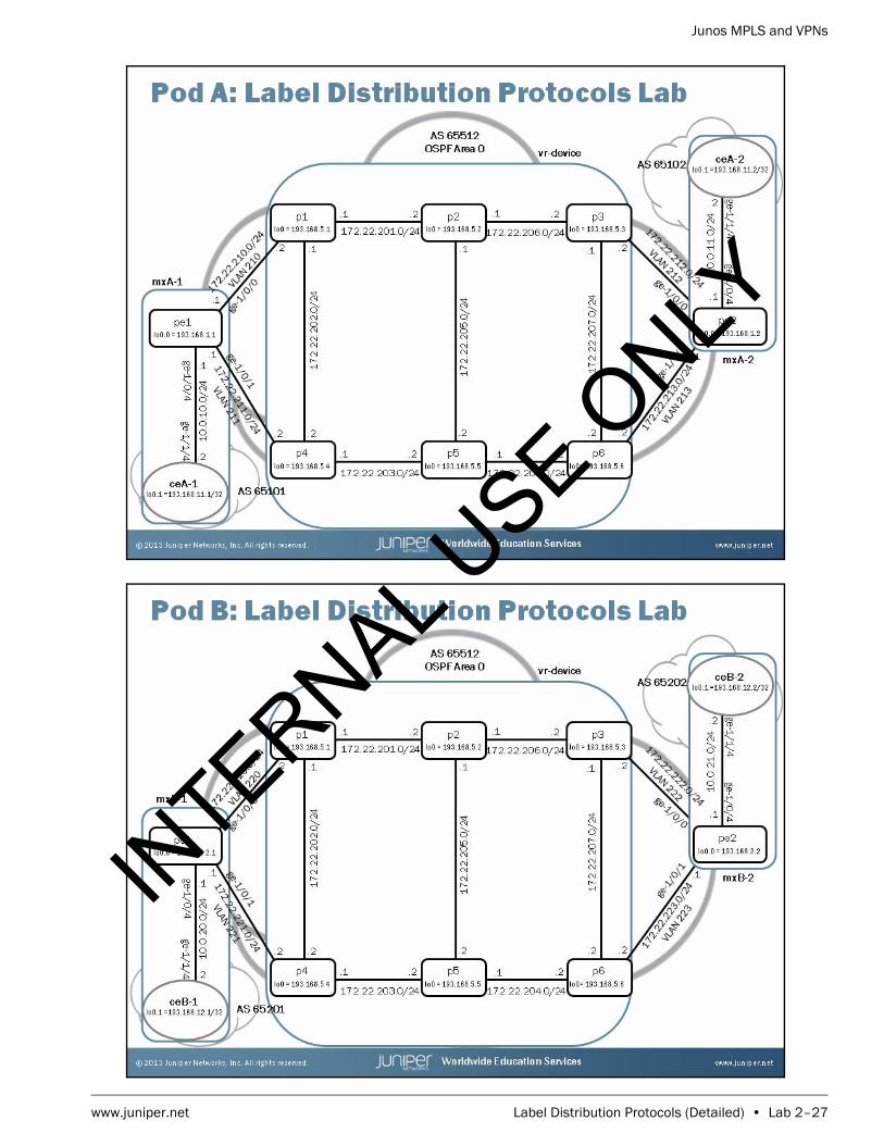
Junos MPLS and VPNs
www.juniper.net Label Distribution Protocols (Detailed) • Lab 2–27
INTERNAL U
SE ONLY

Junos MPLS and VPNs
Lab 2–28 • Label Distribution Protocols (Detailed) www.juniper.net
INTERNAL U
SE ONLY

www.juniper.net CSPF (Detailed) • Lab 3–1
LabCSPF (Detailed)
Overview
In this lab, you create a baseline multiprotocol label switching (MPLS) network and then create label switched paths (LSPs) using administrative groups as a constraint for constrained shortest path first (CSPF).
The lab is available in two formats: a high-level format that is designed to make you think through each step and a detailed format that offers step-by-step instructions complete with sample output from most commands.
By completing this lab, you will perform the following tasks:
• Create a baseline network.
• Define three Resource Reservation Protocol (RSVP) signaled LSPs to the remote provider edge (PE) router.
• Create and assign administrative groups to interfaces and define an LSP using administrative groups as a routing constraint.
• Analyze the traffic engineering database (TED).
INTERNAL U
SE ONLY

Junos MPLS and VPNs
Lab 3–2 • CSPF (Detailed) www.juniper.net
Part 1: Creating the Baseline Network
In this lab part, you will create the baseline network for the lab. You will load a baseline configuration which will configure your router’s interfaces, Open Shortest Path First (OSPF) topology, and the Internal Border Gateway Protocol (IBGP) peering session between the two PE routers. You will then enable RSVP and MPLS on the core-facing interfaces.
Step 1.1
Ensure that you know to which device you are assigned. Check with your instructor if necessary.
Step 1.2
Consult the management network diagram, provided by your instructor, to determine your device’s management address.
Question: What is the management address assigned to your station?
Answer: The answer varies. The sample hostname and IP address used in the output examples in this lab are for mxB-1, which uses 10.210.15.3 as its management IP address. The actual management subnet varies between delivery environments.
Note
The instructor will tell you the nature of your access and will provide you with the necessary details to access your assigned device.
INTERNAL U
SE ONLY

Junos MPLS and VPNs
www.juniper.net CSPF (Detailed) • Lab 3–3
Step 1.3
Access the CLI at your station using either the console, Telnet, or Secure Shell (SSH) as directed by your instructor. The following example shows simple Telnet access to mxB-1 using the Secure CRT program.
Step 1.4
Log in as user lab with the password supplied by your instructor. Enter configuration mode and load the reset configuration file jmv/lab3-start.config. Commit the configuration and return to operational mode.
mxB-1 (ttyp0)
login: labPassword:
--- JUNOS 12.3R2.5 built 2013-03-22 17:12:14 UTClab@mxB-1> configure Entering configuration mode
[edit]lab@mxB-1# load override jmv/lab3-start.config load complete
[edit]lab@mxB-1# commit and-quit commit completeExiting configuration mode
lab@mxB-1>
Step 1.5
Verify that your Open Shortest Path First (OSPF) neighbor relationships are up and operational.
INTERNAL U
SE ONLY

Junos MPLS and VPNs
Lab 3–4 • CSPF (Detailed) www.juniper.net
lab@mxB-1> show ospf neighbor Address Interface State ID Pri Dead172.22.220.2 ge-1/0/0.220 Full 193.168.5.1 128 34172.22.221.2 ge-1/0/1.221 Full 193.168.5.4 128 39
Question: What is the state of your PE router’s OSPF neighbors?
Answer: After a short time, the OSPF neighbors should attain the Full state.
Step 1.6
Verify that your PE router has established an IBGP neighbor relationship with the remote PE router.
lab@mxB-1> show bgp neighborPeer: 193.168.2.2+179 AS 65512 Local: 193.168.2.1+58282 AS 65512 Type: Internal State: Established Flags: <Sync> Last State: OpenConfirm Last Event: RecvKeepAlive Last Error: None Options: <Preference LocalAddress Refresh> Local Address: 193.168.2.1 Holdtime: 90 Preference: 170 Number of flaps: 0 Peer ID: 193.168.2.2 Local ID: 193.168.2.1 Active Holdtime: 90 Keepalive Interval: 30 Group index: 0 Peer index: 0 BFD: disabled, down NLRI for restart configured on peer: inet-unicast NLRI advertised by peer: inet-unicast NLRI for this session: inet-unicast Peer supports Refresh capability (2) Stale routes from peer are kept for: 300 Peer does not support Restarter functionality NLRI that restart is negotiated for: inet-unicast NLRI of received end-of-rib markers: inet-unicast NLRI of all end-of-rib markers sent: inet-unicast Peer supports 4 byte AS extension (peer-as 65512) Peer does not support Addpath Table inet.0 Bit: 10001 RIB State: BGP restart is complete Send state: in sync Active prefixes: 0 Received prefixes: 0 Accepted prefixes: 0 Suppressed due to damping: 0 Advertised prefixes: 0 Last traffic (seconds): Received 19 Sent 8 Checked 31 Input messages: Total 9219 Updates 4 Refreshes 0 Octets 175246 Output messages: Total 9218 Updates 2 Refreshes 0 Octets 175250 Output Queue[0]: 0
INTERNAL U
SE ONLY

Junos MPLS and VPNs
www.juniper.net CSPF (Detailed) • Lab 3–5
Question: Is the neighbor relationship in the established state with the remote PE router?
Answer: The remote PE router should be in an established state with your PE router. If it is not, double check the interface and BGP settings. If you need further assistance, consult with your instructor.
Step 1.7
Enter into configuration mode and navigate to the [edit interfaces] hierarchy. Configure the core facing interfaces to allow multiprotocol label switching (MPLS) traffic.
lab@mxB-1> configure Entering configuration mode
[edit]lab@mxB-1# edit interfaces
[edit interfaces]lab@mxB-1# set ge-1/0/0 unit unit family mpls
[edit interfaces]lab@mxB-1# set ge-1/0/1 unit unit family mpls
[edit interfaces]lab@mxB-1#
Step 1.8
Navigate to [edit protocols mpls] hierarchy and add the interface all statement. As good practice please be sure to disable the management interface.
[edit interfaces]lab@mxB-1# top edit protocols mpls
[edit protocols mpls]lab@mxB-1# set interface ge-1/0/0.unit
[edit protocols mpls]lab@mxB-1# set interface ge-1/0/1.unit
Step 1.9
Commit the configuration changes and review the interfaces that are participating in MPLS to ensure we have the proper configuration by executing the run show mpls interface command.
[edit protocols mpls]lab@mxB-1# commit commit complete
INTERNAL U
SE ONLY

Junos MPLS and VPNs
Lab 3–6 • CSPF (Detailed) www.juniper.net
[edit protocols mpls]lab@mxB-1# run show mpls interface Interface State Administrative groups (x: extended)ge-1/0/0.220 Up <none>ge-1/0/1.221 Up <none>
Step 1.10
Navigate to the [edit protocols rsvp] hierarchy. Add the appropriate core facing interfaces manually. Remember that you must specify the correct unit number when adding interfaces to any protocol configuration. The default Junos OS behavior is to assume unit 0 if no unit is specified. Review the configuration before committing to ensure the interfaces are correct.
[edit protocols mpls]lab@mxB-1# top edit protocols rsvp
[edit protocols rsvp]lab@mxB-1# set interface ge-1/0/0.unit
[edit protocols rsvp]lab@mxB-1# set interface ge-1/0/1.unit
[edit protocols rsvp]lab@mxB-1# show interface ge-1/0/0.220;interface ge-1/0/1.221;
[edit protocols rsvp]lab@mxB-1# commit and quitcommit complete
Step 1.11
Using show commands, verify that the MPLS and RSVP are configured correctly on the core-facing interfaces.
lab@mxB-1> show mpls interface Interface State Administrative groups (x: extended)ge-1/0/0.220 Up <none>ge-1/0/1.221 Up <none>
Note
It is perfectly acceptable to use the interface all option when adding the interfaces into RSVP. For this lab, however, we ask that you explicitly identify the interfaces to demonstrate the importance of including the correct unit number when manually configuring particular interfaces.
INTERNAL U
SE ONLY

Junos MPLS and VPNs
www.juniper.net CSPF (Detailed) • Lab 3–7
lab@mxB-1> show rsvp interface RSVP interface: 2 active Active Subscr- Static Available Reserved HighwaterInterface State resv iption BW BW BW markge-1/0/0.220Up 0 100% 1000Mbps 1000Mbps 0bps 0bps ge-1/0/1.221Up 0 100% 1000Mbps 1000Mbps 0bps 0bps
Question: Can your core-facing interfaces now support the transmission of MPLS packets?
Answer: The outputs of the two commands show that the two interfaces can now support the forwarding of MPLS packets.
Part 2: Enabling the TED
By default, the Junos operating system does not support the flooding the Opaque LSAs used to build the TED. This feature must be enabled on every router in the OSPF network. In this lab part, you will enable the TED and verify its operation.
Step 2.1
View the OSPF database and determine what types of link state advertisements (LSAs) are currently being flooded in the network.
lab@mxB-1> show ospf database
Area 0.0.0.0 Type ID Adv Rtr Seq Age Opt Cksum Len Router *193.168.2.1 193.168.2.1 0x8000007a 1851 0x22 0x26a4 60Router 193.168.2.2 193.168.2.2 0x800000af 906 0x22 0x5634 60Router 193.168.5.1 193.168.5.1 0x800000b6 127 0x22 0xe735 96Router 193.168.5.2 193.168.5.2 0x800000af 1469 0x22 0x2771 72Router 193.168.5.3 193.168.5.3 0x800000b2 2267 0x22 0x37c6 96Router 193.168.5.4 193.168.5.4 0x800000b4 2900 0x22 0xb15b 96Router 193.168.5.5 193.168.5.5 0x800000ae 1468 0x22 0x1679 72Router 193.168.5.6 193.168.5.6 0x800000b1 1770 0x22 0x1927 108Network 172.22.201.2 193.168.5.2 0x800000ac 1969 0x22 0xd3d8 32Network 172.22.202.2 193.168.5.4 0x800000ad 758 0x22 0xced7 32Network 172.22.203.2 193.168.5.5 0x800000ac 2754 0x22 0xf3ad 32Network 172.22.204.2 193.168.5.6 0x800000ac 2520 0x22 0xfaa2 32Network 172.22.205.2 193.168.5.5 0x800000ac 1897 0x22 0xc1df 32Network 172.22.206.2 193.168.5.3 0x800000ad 124 0x22 0xacf6 32Network 172.22.207.2 193.168.5.6 0x800000ad 270 0x22 0xbbdf 32Network 172.22.220.2 193.168.5.1 0x80000054 2127 0x22 0x876f 32Network 172.22.221.2 193.168.5.4 0x80000054 2043 0x22 0x8867 32Network 172.22.222.2 193.168.5.3 0x800000ae 1410 0x22 0xd2c2 32Network 172.22.223.2 193.168.5.6 0x800000ae 1020 0x22 0xd3ba 32OpaqArea 1.0.0.1 193.168.2.2 0x80000001 457 0x22 0xb49d 28OpaqArea 1.0.0.1 193.168.5.1 0x800000ae 627 0x22 0x5b45 28OpaqArea 1.0.0.1 193.168.5.2 0x800000ad 969 0x22 0x613e 28
INTERNAL U
SE ONLY

Junos MPLS and VPNs
Lab 3–8 • CSPF (Detailed) www.juniper.net
OpaqArea 1.0.0.1 193.168.5.3 0x800000ad 981 0x22 0x6538 28OpaqArea 1.0.0.1 193.168.5.4 0x800000ae 329 0x22 0x6733 28OpaqArea 1.0.0.1 193.168.5.5 0x800000ad 1040 0x22 0x6d2c 28OpaqArea 1.0.0.1 193.168.5.6 0x800000ad 2145 0x22 0x7126 28OpaqArea 1.0.0.3 193.168.2.2 0x80000001 457 0x22 0x65cf 124OpaqArea 1.0.0.3 193.168.5.1 0x800000ad 1627 0x22 0x8f19 124OpaqArea 1.0.0.3 193.168.5.2 0x800000ad 469 0x22 0x7d24 124OpaqArea 1.0.0.3 193.168.5.3 0x800000ad 553 0x22 0x950a 124OpaqArea 1.0.0.3 193.168.5.4 0x80000054 2472 0x22 0x5e7d 124OpaqArea 1.0.0.3 193.168.5.5 0x800000ad 611 0x22 0x8517 124OpaqArea 1.0.0.3 193.168.5.6 0x800000ad 645 0x22 0x5f37 124OpaqArea 1.0.0.4 193.168.2.2 0x80000001 457 0x22 0x8da4 124OpaqArea 1.0.0.4 193.168.5.1 0x800000ad 1127 0x22 0xfca8 124OpaqArea 1.0.0.4 193.168.5.2 0x800000ac 2969 0x22 0x6b2e 124OpaqArea 1.0.0.4 193.168.5.3 0x800000ad 1838 0x22 0x274 124OpaqArea 1.0.0.4 193.168.5.4 0x800000ad 1615 0x22 0xd0d3 124OpaqArea 1.0.0.4 193.168.5.5 0x800000ad 183 0x22 0xe8b9 124OpaqArea 1.0.0.4 193.168.5.6 0x800000ac 2895 0x22 0x9505 124OpaqArea 1.0.0.5 193.168.5.1 0x80000054 2627 0x22 0x5282 124OpaqArea 1.0.0.5 193.168.5.2 0x800000ac 2469 0x22 0xd96 124OpaqArea 1.0.0.5 193.168.5.3 0x800000ac 2695 0x22 0x4158 124OpaqArea 1.0.0.5 193.168.5.4 0x800000ad 1186 0x22 0x871b 124OpaqArea 1.0.0.5 193.168.5.5 0x800000ac 2325 0x22 0x6d27 124OpaqArea 1.0.0.5 193.168.5.6 0x800000ad 1395 0x22 0xef8a 124
Question: What types of LSAs are being flooded in the OSPF domain?
Answer: You should see Router, Network, and OpaqArea LSAs.
Question: Is your router generating an OpaqArea LSA?
Answer: Looking at the Adv Rtr field, you should notice that your router is not generating the OpaqArea LSA. The provider routers have been configured to allow for the flooding of the OpaqArea LSA.
Step 2.2
View the TED and determine whether or not your router is using the OpaqArea LSAs to build a TED.
INTERNAL U
SE ONLY
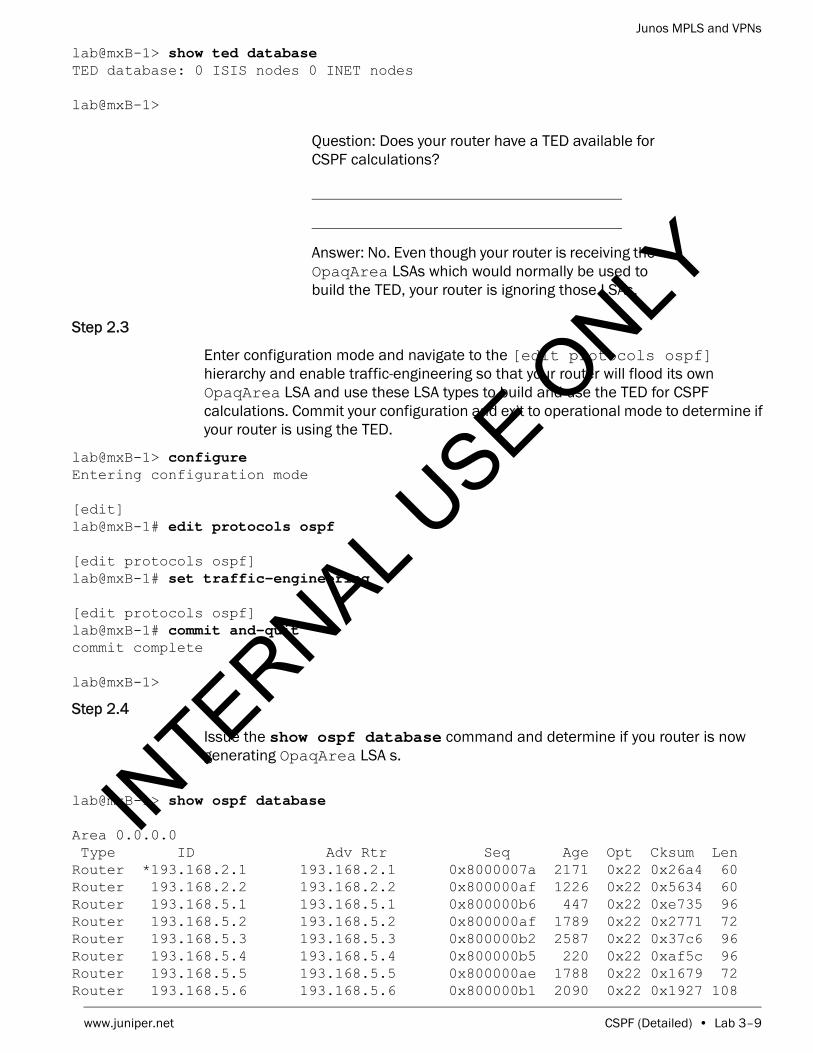
Junos MPLS and VPNs
www.juniper.net CSPF (Detailed) • Lab 3–9
lab@mxB-1> show ted database TED database: 0 ISIS nodes 0 INET nodes
lab@mxB-1>
Question: Does your router have a TED available for CSPF calculations?
Answer: No. Even though your router is receiving the OpaqArea LSAs which would normally be used to build the TED, your router is ignoring those LSAs.
Step 2.3
Enter configuration mode and navigate to the [edit protocols ospf] hierarchy and enable traffic-engineering so that your router will flood its own OpaqArea LSA and use these LSA types to build and use the TED for CSPF calculations. Commit your configuration and exit to operational mode to determine if your router is using the TED.
lab@mxB-1> configure Entering configuration mode
[edit]lab@mxB-1# edit protocols ospf
[edit protocols ospf]lab@mxB-1# set traffic-engineering
[edit protocols ospf]lab@mxB-1# commit and-quit commit complete
lab@mxB-1>
Step 2.4
Issue the show ospf database command and determine if you router is now generating OpaqArea LSA s.
lab@mxB-1> show ospf database
Area 0.0.0.0 Type ID Adv Rtr Seq Age Opt Cksum Len Router *193.168.2.1 193.168.2.1 0x8000007a 2171 0x22 0x26a4 60Router 193.168.2.2 193.168.2.2 0x800000af 1226 0x22 0x5634 60Router 193.168.5.1 193.168.5.1 0x800000b6 447 0x22 0xe735 96Router 193.168.5.2 193.168.5.2 0x800000af 1789 0x22 0x2771 72Router 193.168.5.3 193.168.5.3 0x800000b2 2587 0x22 0x37c6 96Router 193.168.5.4 193.168.5.4 0x800000b5 220 0x22 0xaf5c 96Router 193.168.5.5 193.168.5.5 0x800000ae 1788 0x22 0x1679 72Router 193.168.5.6 193.168.5.6 0x800000b1 2090 0x22 0x1927 108
INTERNAL U
SE ONLY

Junos MPLS and VPNs
Lab 3–10 • CSPF (Detailed) www.juniper.net
Network 172.22.201.2 193.168.5.2 0x800000ac 2289 0x22 0xd3d8 32Network 172.22.202.2 193.168.5.4 0x800000ad 1078 0x22 0xced7 32Network 172.22.203.2 193.168.5.5 0x800000ad 74 0x22 0xf1ae 32Network 172.22.204.2 193.168.5.6 0x800000ac 2840 0x22 0xfaa2 32Network 172.22.205.2 193.168.5.5 0x800000ac 2217 0x22 0xc1df 32Network 172.22.206.2 193.168.5.3 0x800000ad 444 0x22 0xacf6 32Network 172.22.207.2 193.168.5.6 0x800000ad 590 0x22 0xbbdf 32Network 172.22.220.2 193.168.5.1 0x80000054 2447 0x22 0x876f 32Network 172.22.221.2 193.168.5.4 0x80000054 2363 0x22 0x8867 32Network 172.22.222.2 193.168.5.3 0x800000ae 1730 0x22 0xd2c2 32Network 172.22.223.2 193.168.5.6 0x800000ae 1340 0x22 0xd3ba 32OpaqArea*1.0.0.1 193.168.2.1 0x80000001 71 0x22 0xb0a3 28OpaqArea 1.0.0.1 193.168.2.2 0x80000001 777 0x22 0xb49d 28OpaqArea 1.0.0.1 193.168.5.1 0x800000ae 947 0x22 0x5b45 28OpaqArea 1.0.0.1 193.168.5.2 0x800000ad 1289 0x22 0x613e 28OpaqArea 1.0.0.1 193.168.5.3 0x800000ad 1301 0x22 0x6538 28OpaqArea 1.0.0.1 193.168.5.4 0x800000ae 649 0x22 0x6733 28OpaqArea 1.0.0.1 193.168.5.5 0x800000ad 1360 0x22 0x6d2c 28OpaqArea 1.0.0.1 193.168.5.6 0x800000ad 2465 0x22 0x7126 28OpaqArea*1.0.0.3 193.168.2.1 0x80000001 71 0x22 0x733 124OpaqArea 1.0.0.3 193.168.2.2 0x80000001 777 0x22 0x65cf 124OpaqArea 1.0.0.3 193.168.5.1 0x800000ad 1947 0x22 0x8f19 124OpaqArea 1.0.0.3 193.168.5.2 0x800000ad 789 0x22 0x7d24 124OpaqArea 1.0.0.3 193.168.5.3 0x800000ad 873 0x22 0x950a 124OpaqArea 1.0.0.3 193.168.5.4 0x80000054 2792 0x22 0x5e7d 124OpaqArea 1.0.0.3 193.168.5.5 0x800000ad 931 0x22 0x8517 124OpaqArea 1.0.0.3 193.168.5.6 0x800000ad 965 0x22 0x5f37 124OpaqArea*1.0.0.4 193.168.2.1 0x80000001 71 0x22 0x2f08 124OpaqArea 1.0.0.4 193.168.2.2 0x80000001 777 0x22 0x8da4 124OpaqArea 1.0.0.4 193.168.5.1 0x800000ad 1447 0x22 0xfca8 124OpaqArea 1.0.0.4 193.168.5.2 0x800000ad 289 0x22 0x692f 124OpaqArea 1.0.0.4 193.168.5.3 0x800000ad 2158 0x22 0x274 124OpaqArea 1.0.0.4 193.168.5.4 0x800000ad 1935 0x22 0xd0d3 124OpaqArea 1.0.0.4 193.168.5.5 0x800000ad 503 0x22 0xe8b9 124OpaqArea 1.0.0.4 193.168.5.6 0x800000ad 215 0x22 0x9306 124OpaqArea 1.0.0.5 193.168.5.1 0x80000054 2947 0x22 0x5282 124OpaqArea 1.0.0.5 193.168.5.2 0x800000ac 2789 0x22 0xd96 124OpaqArea 1.0.0.5 193.168.5.3 0x800000ad 15 0x22 0x3f59 124OpaqArea 1.0.0.5 193.168.5.4 0x800000ad 1506 0x22 0x871b 124OpaqArea 1.0.0.5 193.168.5.5 0x800000ac 2645 0x22 0x6d27 124OpaqArea 1.0.0.5 193.168.5.6 0x800000ad 1715 0x22 0xef8a 124
Question: Is your router generating an OpaqArea LSA?
Answer: Looking at the Adv Rtr field, you should notice that your router is now generating the OpaqArea LSAs.
Step 2.5
Issue the show ted database command to determine if your router is using the OpaqArea LSAs to build a TED database.
INTERNAL U
SE ONLY
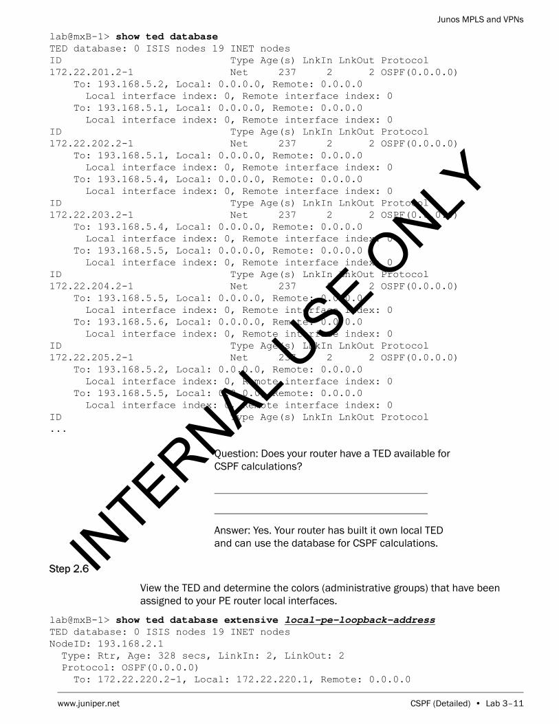
Junos MPLS and VPNs
www.juniper.net CSPF (Detailed) • Lab 3–11
lab@mxB-1> show ted database TED database: 0 ISIS nodes 19 INET nodesID Type Age(s) LnkIn LnkOut Protocol172.22.201.2-1 Net 237 2 2 OSPF(0.0.0.0) To: 193.168.5.2, Local: 0.0.0.0, Remote: 0.0.0.0 Local interface index: 0, Remote interface index: 0 To: 193.168.5.1, Local: 0.0.0.0, Remote: 0.0.0.0 Local interface index: 0, Remote interface index: 0ID Type Age(s) LnkIn LnkOut Protocol172.22.202.2-1 Net 237 2 2 OSPF(0.0.0.0) To: 193.168.5.1, Local: 0.0.0.0, Remote: 0.0.0.0 Local interface index: 0, Remote interface index: 0 To: 193.168.5.4, Local: 0.0.0.0, Remote: 0.0.0.0 Local interface index: 0, Remote interface index: 0ID Type Age(s) LnkIn LnkOut Protocol172.22.203.2-1 Net 237 2 2 OSPF(0.0.0.0) To: 193.168.5.4, Local: 0.0.0.0, Remote: 0.0.0.0 Local interface index: 0, Remote interface index: 0 To: 193.168.5.5, Local: 0.0.0.0, Remote: 0.0.0.0 Local interface index: 0, Remote interface index: 0ID Type Age(s) LnkIn LnkOut Protocol172.22.204.2-1 Net 237 2 2 OSPF(0.0.0.0) To: 193.168.5.5, Local: 0.0.0.0, Remote: 0.0.0.0 Local interface index: 0, Remote interface index: 0 To: 193.168.5.6, Local: 0.0.0.0, Remote: 0.0.0.0 Local interface index: 0, Remote interface index: 0ID Type Age(s) LnkIn LnkOut Protocol172.22.205.2-1 Net 237 2 2 OSPF(0.0.0.0) To: 193.168.5.2, Local: 0.0.0.0, Remote: 0.0.0.0 Local interface index: 0, Remote interface index: 0 To: 193.168.5.5, Local: 0.0.0.0, Remote: 0.0.0.0 Local interface index: 0, Remote interface index: 0ID Type Age(s) LnkIn LnkOut Protocol...
Question: Does your router have a TED available for CSPF calculations?
Answer: Yes. Your router has built it own local TED and can use the database for CSPF calculations.
Step 2.6
View the TED and determine the colors (administrative groups) that have been assigned to your PE router local interfaces.
lab@mxB-1> show ted database extensive local-pe-loopback-address TED database: 0 ISIS nodes 19 INET nodesNodeID: 193.168.2.1 Type: Rtr, Age: 328 secs, LinkIn: 2, LinkOut: 2 Protocol: OSPF(0.0.0.0) To: 172.22.220.2-1, Local: 172.22.220.1, Remote: 0.0.0.0
INTERNAL U
SE ONLY

Junos MPLS and VPNs
Lab 3–12 • CSPF (Detailed) www.juniper.net
Local interface index: 0, Remote interface index: 0 Color: 0 <none> Metric: 1 Static BW: 1000Mbps Reservable BW: 1000Mbps Available BW [priority] bps: [0] 1000Mbps [1] 1000Mbps [2] 1000Mbps [3] 1000Mbps [4] 1000Mbps [5] 1000Mbps [6] 1000Mbps [7] 1000Mbps Interface Switching Capability Descriptor(1): Switching type: Packet Encoding type: Packet Maximum LSP BW [priority] bps: [0] 1000Mbps [1] 1000Mbps [2] 1000Mbps [3] 1000Mbps [4] 1000Mbps [5] 1000Mbps [6] 1000Mbps [7] 1000Mbps To: 172.22.221.2-1, Local: 172.22.221.1, Remote: 0.0.0.0 Local interface index: 0, Remote interface index: 0 Color: 0 <none> Metric: 1 Static BW: 1000Mbps Reservable BW: 1000Mbps Available BW [priority] bps: [0] 1000Mbps [1] 1000Mbps [2] 1000Mbps [3] 1000Mbps [4] 1000Mbps [5] 1000Mbps [6] 1000Mbps [7] 1000Mbps Interface Switching Capability Descriptor(1): Switching type: Packet Encoding type: Packet Maximum LSP BW [priority] bps: [0] 1000Mbps [1] 1000Mbps [2] 1000Mbps [3] 1000Mbps [4] 1000Mbps [5] 1000Mbps [6] 1000Mbps [7] 1000Mbps
Question: Have any colors been assigned to your PE router’s core-facing interfaces?
Answer: No. The TED contains all of the details of the network that can be used by the CSPF algorithm. Currently, both of the core facing interfaces have no colors (administrative groups) assigned.
STOP Do not proceed until the remote team finishes Part 2.
Part 3: Configuring RSVP-Signaled LSPs
In this lab part, you will configure gold, silver, and bronze RSVP-signaled LSPs.
INTERNAL U
SE ONLY

Junos MPLS and VPNs
www.juniper.net CSPF (Detailed) • Lab 3–13
Step 3.1
Enter configuration mode and navigate to the [edit protocols mpls] hierarchy. Configure an RSVP-signaled LSP named lsp-gold-localPE-to-remotePE-pod. For example, if you are assigned router mxB-1, your peer router is mxB-2 and your pod is B. The LSP for mxB-1 should be named lsp-gold-pe1-to-pe2-B. Your LSP should egress at your remote peer’s loopback address. Create and a use a path called path1 to ensure that this LSP traverses P2 as a loose hop.
lab@mxB-1> configure Entering configuration mode
[edit]lab@mxB-1# edit protocols mpls
[edit protocols mpls]lab@mxB-1# set path path1 193.168.5.2 loose
[edit protocols mpls]lab@mxB-1# set label-switched-path lsp-gold-localPE-to-remotePE-pod to remote-pe-loopback-address
[edit protocols mpls]lab@mxB-1# set label-switched-path lsp-gold-localPE-to-remotePE-pod primary path1
[edit protocols mpls]lab@mxB-1#
Step 3.2
Configure an RSVP-signaled LSP named lsp-silver-localPE-to-remotePE-pod. For example, if you are assigned router mxB-1, your peer router is mxB-2 and your pod is B. The LSP for mxB-1 should be named lsp-silver-pe1-to-pe2-B. Your LSP should egress at your remote peer’s loopback address. Use the path called path1 to ensure that this LSP traverses P2 as a loose hop.
[edit protocols mpls]lab@mxB-1# set label-switched-path lsp-silver-localPE-to-remotePE-pod to remote-pe-loopback-address
[edit protocols mpls]lab@mxB-1# set label-switched-path lsp-silver-localPE-to-remotePE-pod primary path1
Step 3.3
Configure an RSVP-signaled LSP named lsp-bronze-localPE-to-remotePE-pod. For example, if you are assigned router mxB-1, your peer router is mxB-2 and your pod is B. The LSP for mxB-1 should be named lsp-bronze-pe1-to-pe2-B. Your LSP should egress at your remote peer’s loopback address. Use the path called path1 to ensure that this LSP traverses P2 as a loose hop. Commit your configuration and exit to operational mode.
INTERNAL U
SE ONLY

Junos MPLS and VPNs
Lab 3–14 • CSPF (Detailed) www.juniper.net
[edit protocols mpls]lab@mxB-1# set label-switched-path lsp-bronze-localPE-to-remotePE-pod to remote-pe-loopback-address
[edit protocols mpls]lab@mxB-1# set label-switched-path lsp-bronze-localPE-to-remotePE-pod primary path1
[edit protocols mpls]lab@mxB-1# commit and-quit commit completeExiting configuration mode
Step 3.4
Using the show rsvp session extensive ingress command, verify that the new LSPs are up and are currently traversing P2.
lab@mxB-1> show rsvp session extensive ingress Ingress RSVP: 3 sessions
193.168.2.2 From: 193.168.2.1, LSPstate: Up, ActiveRoute: 0 LSPname: lsp-gold-pe1-to-pe2-B, LSPpath: Primary LSPtype: Static Configured Suggested label received: -, Suggested label sent: - Recovery label received: -, Recovery label sent: 300288 Resv style: 1 FF, Label in: -, Label out: 300288 Time left: -, Since: Mon May 13 15:36:20 2013 Tspec: rate 0bps size 0bps peak Infbps m 20 M 1500 Port number: sender 1 receiver 47889 protocol 0 PATH rcvfrom: localclient Adspec: sent MTU 1500 Path MTU: received 1500 PATH sentto: 172.22.220.2 (ge-1/0/0.220) 6 pkts RESV rcvfrom: 172.22.220.2 (ge-1/0/0.220) 5 pkts Explct route: 172.22.220.2 172.22.201.2 172.22.206.2 172.22.222.1 Record route: <self> 172.22.220.2 172.22.201.2 172.22.206.2 172.22.222.1
193.168.2.2 From: 193.168.2.1, LSPstate: Up, ActiveRoute: 0 LSPname: lsp-bronze-pe1-to-pe2-B, LSPpath: Primary LSPtype: Static Configured Suggested label received: -, Suggested label sent: - Recovery label received: -, Recovery label sent: 300304 Resv style: 1 FF, Label in: -, Label out: 300304 Time left: -, Since: Mon May 13 15:37:35 2013 Tspec: rate 0bps size 0bps peak Infbps m 20 M 1500 Port number: sender 1 receiver 47890 protocol 0 PATH rcvfrom: localclient Adspec: sent MTU 1500 Path MTU: received 1500 PATH sentto: 172.22.220.2 (ge-1/0/0.220) 3 pkts RESV rcvfrom: 172.22.220.2 (ge-1/0/0.220) 3 pkts Explct route: 172.22.220.2 172.22.201.2 172.22.206.2 172.22.222.1 Record route: <self> 172.22.220.2 172.22.201.2 172.22.206.2 172.22.222.1
INTERNAL U
SE ONLY

Junos MPLS and VPNs
www.juniper.net CSPF (Detailed) • Lab 3–15
193.168.2.2 From: 193.168.2.1, LSPstate: Up, ActiveRoute: 0 LSPname: lsp-silver-pe1-to-pe2-B, LSPpath: Primary LSPtype: Static Configured Suggested label received: -, Suggested label sent: - Recovery label received: -, Recovery label sent: 300320 Resv style: 1 FF, Label in: -, Label out: 300320 Time left: -, Since: Mon May 13 15:37:35 2013 Tspec: rate 0bps size 0bps peak Infbps m 20 M 1500 Port number: sender 1 receiver 47891 protocol 0 PATH rcvfrom: localclient Adspec: sent MTU 1500 Path MTU: received 1500 PATH sentto: 172.22.220.2 (ge-1/0/0.220) 3 pkts RESV rcvfrom: 172.22.220.2 (ge-1/0/0.220) 3 pkts Explct route: 172.22.220.2 172.22.201.2 172.22.206.2 172.22.222.1 Record route: <self> 172.22.220.2 172.22.201.2 172.22.206.2 172.22.222.1 Total 3 displayed, Up 3, Down 0
Question: Are all three LSPs up?
Answer: Yes, each of the LSPs should be up.
Question: What path are each of the LSPs taking through the network? List the routers that the LSPs traverse.
Answer: Each of the three LSPs should be traversing the exact same path. They should be traversing some combination of P1, P2, P3, and the remote PE router. If your LSPs are not taking this path, please check your configuration. To have your router recalculate the path through the network, issue the clear rsvp session command.
Part 4: Adding Administrative Groups to Core-Facing Interfaces
In this lab part, you will add administrative groups to your core-facing interfaces. Refer to the lab diagram to determine the administrative groups to be applied to the interfaces. The P router interfaces have been preconfigured with the administrative groups listed on the diagram.
Step 4.1
Enter configuration mode and navigate to the [edit protocols] hierarchy. Define an administrative group called gold that uses a value of 1.
INTERNAL U
SE ONLY

Junos MPLS and VPNs
Lab 3–16 • CSPF (Detailed) www.juniper.net
lab@mxB-1> configure Entering configuration mode
[edit]lab@mxB-1# edit protocols
[edit protocols]lab@mxB-1# set mpls admin-groups gold 1
Step 4.2
Define an administrative group called silver that uses a value of 2.
[edit protocols]lab@mxB-1# set mpls admin-groups silver 2
Step 4.3
Define an administrative group called bronze that uses a value of 3.
[edit protocols]lab@mxB-1# set mpls admin-groups bronze 3
Step 4.4
Apply the administrative groups (as listed in the lab diagram) to the core-facing interfaces. Commit your configuration and exit to operational mode.
[edit protocols]lab@mxB-1# set mpls interface ge-1/0/0.unit admin-group silver
[edit protocols]lab@mxB-1# set mpls interface ge-1/0/0.unit admin-group bronze
[edit protocols]lab@mxB-1# set mpls interface ge-1/0/1.unit admin-group gold
[edit protocols]lab@mxB-1# commit and-quit commit completeExiting configuration mode
lab@mxB-1>
Step 4.5
Use the show mpls interface command to verify that the correct administrative groups have been applied to your interfaces.
lab@mxB-1> show mpls interface Interface State Administrative groupsge-1/0/0.220 Up bronze silverge-1/0/1.221 Up gold
INTERNAL U
SE ONLY

Junos MPLS and VPNs
www.juniper.net CSPF (Detailed) • Lab 3–17
Question: What administrative group have been applied to the interfaces?
Answer: On your PE routers, the ge-1/0/0 interface should be listed as silver and bronze. The ge-1/0/1 interface should be listed as gold.
Step 4.6
View the TED and determine whether your router is advertising the correct colors (administrative groups) to all other routers in the network.
lab@mxB-1> show ted database local-pe-loopback-address extensive TED database: 0 ISIS nodes 19 INET nodesNodeID: 193.168.2.1 Type: Rtr, Age: 74 secs, LinkIn: 2, LinkOut: 2 Protocol: OSPF(0.0.0.0) To: 172.22.220.2-1, Local: 172.22.220.1, Remote: 0.0.0.0 Local interface index: 0, Remote interface index: 0 Color: 0xc bronze silver Metric: 1 Static BW: 1000Mbps Reservable BW: 1000Mbps Available BW [priority] bps: [0] 1000Mbps [1] 1000Mbps [2] 1000Mbps [3] 1000Mbps [4] 1000Mbps [5] 1000Mbps [6] 1000Mbps [7] 1000Mbps Interface Switching Capability Descriptor(1): Switching type: Packet Encoding type: Packet Maximum LSP BW [priority] bps: [0] 1000Mbps [1] 1000Mbps [2] 1000Mbps [3] 1000Mbps [4] 1000Mbps [5] 1000Mbps [6] 1000Mbps [7] 1000Mbps To: 172.22.221.2-1, Local: 172.22.221.1, Remote: 0.0.0.0 Local interface index: 0, Remote interface index: 0 Color: 0x2 gold Metric: 1 Static BW: 1000Mbps Reservable BW: 1000Mbps Available BW [priority] bps: [0] 1000Mbps [1] 1000Mbps [2] 1000Mbps [3] 1000Mbps [4] 1000Mbps [5] 1000Mbps [6] 1000Mbps [7] 1000Mbps Interface Switching Capability Descriptor(1): Switching type: Packet Encoding type: Packet Maximum LSP BW [priority] bps: [0] 1000Mbps [1] 1000Mbps [2] 1000Mbps [3] 1000Mbps [4] 1000Mbps [5] 1000Mbps [6] 1000Mbps [7] 1000Mbps
INTERNAL U
SE ONLY

Junos MPLS and VPNs
Lab 3–18 • CSPF (Detailed) www.juniper.net
Question: Is your router advertising the correct color settings to other routers in the network?
Answer: In the TED, the ge-1/0/0 interface should be listed as silver and bronze. The ge-1/0/1 interface should be listed as gold.
STOP Do not proceed until the remote team finishes Part 4.
Part 5: Configuring LSPs to Take Gold, Silver, and Bronze Paths Using CSPF
In this lab part, you will modify the configuration of your LSPs so that they will take a particular path through the network. By specifying the administrative groups to include in the CSPF algorithm, the gold LSP will take the gold path, the silver LSP will take the silver path, and the bronze LSP will take the bronze path through the network.
Step 5.1
Enter configuration mode and navigate to the [edit protocols mpls] hierarchy, Modify the primary path for the gold LSP so that it takes only the gold path through the lab network, ensuring that it continues to pass through P2.
lab@mxB-1> configure Entering configuration mode
[edit]lab@mxB-1# edit protocols mpls
[edit protocols mpls]lab@mxB-1# set label-switched-path lsp-gold-localPE-to-remotePE-pod primary path1 admin-group include-any gold
[edit protocols mpls]lab@mxB-1#
Step 5.2
Modify the primary path for the silver LSP so that it takes only the silver path through the lab network ensuring that it continues to pass through P2.
[edit protocols mpls]lab@mxB-1# set label-switched-path lsp-silver-localPE-to-remotePE-pod primary path1 admin-group include-any silver
INTERNAL U
SE ONLY

Junos MPLS and VPNs
www.juniper.net CSPF (Detailed) • Lab 3–19
Step 5.3
Modify the primary path for the bronze LSP so that it takes only the bronze path through the lab network ensuring that it continues to pass through P2. Commit your configuration and exit to operational mode.
[edit protocols mpls]lab@mxB-1# set label-switched-path lsp-bronze-localPE-to-remotePE-pod primary path1 admin-group include-any bronze
[edit protocols mpls]lab@mxB-1# show admin-groups { gold 1; silver 2; bronze 3;}label-switched-path lsp-gold-pe1-to-pe2-B { to 193.168.2.2; primary path1 { admin-group include-any gold; }}label-switched-path lsp-silver-pe1-to-pe2-B { to 193.168.2.2; primary path1 { admin-group include-any silver; }}label-switched-path lsp-bronze-pe1-to-pe2-B { to 193.168.2.2; primary path1 { admin-group include-any bronze; }}path path1 { 193.168.5.2 loose;}interface ge-1/0/0.220 { admin-group [ silver bronze ];}interface ge-1/0/1.221 { admin-group gold;}
[edit protocols mpls]lab@mxB-1# commit and-quit commit completeExiting configuration mode
Step 5.4
Use the show rsvp session ingress detail command to verify that each LSP is traversing the correct, colored path as well as passing through P2.
lab@mxB-1> show rsvp session ingress detail Ingress RSVP: 3 sessions
INTERNAL U
SE ONLY

Junos MPLS and VPNs
Lab 3–20 • CSPF (Detailed) www.juniper.net
193.168.2.2 From: 193.168.2.1, LSPstate: Up, ActiveRoute: 0 LSPname: lsp-gold-pe1-to-pe2-B, LSPpath: Primary LSPtype: Static Configured Suggested label received: -, Suggested label sent: - Recovery label received: -, Recovery label sent: 300240 Resv style: 1 FF, Label in: -, Label out: 300240 Time left: -, Since: Mon May 13 16:05:23 2013 Tspec: rate 0bps size 0bps peak Infbps m 20 M 1500 Port number: sender 2 receiver 47889 protocol 0 PATH rcvfrom: localclient Adspec: sent MTU 1500 Path MTU: received 1500 PATH sentto: 172.22.221.2 (ge-1/0/1.221) 4 pkts RESV rcvfrom: 172.22.221.2 (ge-1/0/1.221) 4 pkts Explct route: 172.22.221.2 172.22.202.1 172.22.201.2 172.22.205.2 172.22.204.2 172.22.223.1 Record route: <self> 172.22.221.2 172.22.202.1 172.22.201.2 172.22.205.2 172.22.204.2 172.22.223.1
193.168.2.2 From: 193.168.2.1, LSPstate: Up, ActiveRoute: 0 LSPname: lsp-bronze-pe1-to-pe2-B, LSPpath: Primary LSPtype: Static Configured Suggested label received: -, Suggested label sent: - Recovery label received: -, Recovery label sent: 300400 Resv style: 1 FF, Label in: -, Label out: 300400 Time left: -, Since: Mon May 13 16:05:23 2013 Tspec: rate 0bps size 0bps peak Infbps m 20 M 1500 Port number: sender 2 receiver 47890 protocol 0 PATH rcvfrom: localclient Adspec: sent MTU 1500 Path MTU: received 1500 PATH sentto: 172.22.220.2 (ge-1/0/0.220) 4 pkts RESV rcvfrom: 172.22.220.2 (ge-1/0/0.220) 4 pkts Explct route: 172.22.220.2 172.22.201.2 172.22.205.2 172.22.204.2 172.22.207.1 172.22.222.1 Record route: <self> 172.22.220.2 172.22.201.2 172.22.205.2 172.22.204.2 172.22.207.1 172.22.222.1
193.168.2.2 From: 193.168.2.1, LSPstate: Up, ActiveRoute: 0 LSPname: lsp-silver-pe1-to-pe2-B, LSPpath: Primary LSPtype: Static Configured Suggested label received: -, Suggested label sent: - Recovery label received: -, Recovery label sent: 300416 Resv style: 1 FF, Label in: -, Label out: 300416 Time left: -, Since: Mon May 13 16:05:23 2013 Tspec: rate 0bps size 0bps peak Infbps m 20 M 1500 Port number: sender 2 receiver 47891 protocol 0 PATH rcvfrom: localclient Adspec: sent MTU 1500
INTERNAL U
SE ONLY

Junos MPLS and VPNs
www.juniper.net CSPF (Detailed) • Lab 3–21
Path MTU: received 1500 PATH sentto: 172.22.220.2 (ge-1/0/0.220) 4 pkts RESV rcvfrom: 172.22.220.2 (ge-1/0/0.220) 4 pkts Explct route: 172.22.220.2 172.22.202.2 172.22.203.2 172.22.205.1 172.22.206.2 172.22.222.1 Record route: <self> 172.22.220.2 172.22.202.2 172.22.203.2 172.22.205.1 172.22.206.2 172.22.222.1 Total 3 displayed, Up 3, Down 0
Question: List the routers that the gold LSP traverses. Does it traverse the expected path?
Answer: The gold LSP traverses all routers along the gold path including P2. This path is expected.
Question: List the routers that the silver LSP traverses. Does it traverse the expected path?
Answer: The silver LSP traverses all routers along the silver path including P2. This path is expected.
Question: List the routers that the bronze LSP traverses. Does it traverse the expected path?
Answer: The bronze LSP traverses all routers along the bronze path including P2. This path is expected.
Step 5.5
Log out of your assigned device using the exit command.
lab@mxB-1> exit
mxB-1 (ttyu0)
login:
STOP Tell your instructor that you have completed this lab.
INTERNAL U
SE ONLY

Junos MPLS and VPNs
Lab 3–22 • CSPF (Detailed) www.juniper.net
INTERNAL U
SE ONLY

Junos MPLS and VPNs
www.juniper.net CSPF (Detailed) • Lab 3–23
INTERNAL U
SE ONLY

Junos MPLS and VPNs
Lab 3–24 • CSPF (Detailed) www.juniper.net
INTERNAL U
SE ONLY

www.juniper.net Traffic Protection (Detailed) • Lab 4–1
LabTraffic Protection (Detailed)
Overview
In this lab, you will load a baseline multiprotocol label switching (MPLS) network and then create label switched paths (LSPs) using different traffic protection mechanisms.
The lab is available in two formats: a high-level format that is designed to make you think through each step and a detailed format that offers step-by-step instructions complete with sample output from most commands.
By completing this lab, you will perform the following tasks:
• Load a baseline network.
• Define an Resource Reservation Protocol (RSVP) signaled LSP to the remote provider edge (PE) router.
• Add primary/secondary path protection to an LSP.
• Add secondary/secondary path protection to an LSP.
• Add fast-reroute protection to an LSP.
• Add node-link protection to an LSP.
• Add link protection to an LSP.
INTERNAL U
SE ONLY

Junos MPLS and VPNs
Lab 4–2 • Traffic Protection (Detailed) www.juniper.net
Part 1: Creating the Baseline Network
In this lab part, you will create the baseline network for the lab. You will load a baseline configuration which will configure your router’s interfaces, Open Shortest Path First (OSPF) topology, and the Internal Border Gateway Protocol (IBGP) peering session between the two PE routers. The configuration will also enable RSVP and MPLS on the core-facing interfaces. Please refer to the lab diagram titled “Traffic Protection Lab”.
Step 1.1
Ensure that you know to which device you are assigned. Check with your instructor if necessary.
Step 1.2
Consult the management network diagram, provided by your instructor, to determine your device’s management address.
Question: What is the management address assigned to your station?
Answer: The answer varies. The sample hostname and IP address used in the output examples in this lab are for mxB-1, which uses 10.210.15.3 as its management IP address. The actual management subnet varies between delivery environments.
Note
The instructor will tell you the nature of your access and will provide you with the necessary details to access your assigned device.
INTERNAL U
SE ONLY

Junos MPLS and VPNs
www.juniper.net Traffic Protection (Detailed) • Lab 4–3
Step 1.3
Access the CLI at your station using either the console, Telnet, or Secure Shell (SSH) as directed by your instructor. The following example shows simple Telnet access to mxB-1 using the Secure CRT program.
Step 1.4
Log in as user lab with the password supplied by your instructor. Enter configuration mode and load the reset configuration file jmv/lab4-start.config. Commit the configuration and return to operational mode.
mxB-1 (ttyp0)
login: labPassword:
--- JUNOS 12.3R2.5 built 2013-03-22 17:12:14 UTClab@mxB-1> configure Entering configuration mode
[edit]lab@mxB-1# load override jmv/lab4-start.config load complete
[edit]lab@mxB-1# commit and-quit commit completeExiting configuration mode
lab@mxB-1>
Step 1.5
Verify that your Open Shortest Path First (OSPF) neighbor relationships are up and operational.
INTERNAL U
SE ONLY

Junos MPLS and VPNs
Lab 4–4 • Traffic Protection (Detailed) www.juniper.net
lab@mxB-1> show ospf neighbor Address Interface State ID Pri Dead172.22.220.2 ge-1/0/0.220 Full 193.168.5.1 128 34172.22.221.2 ge-1/0/1.221 Full 193.168.5.4 128 39
Question: What is the state of your PE router’s OSPF neighbors?
Answer: After a short time, the OSPF neighbors should attain the Full state.
Step 1.6
Verify that your PE router has established an IBGP neighbor relationship with the remote PE router.
lab@mxB-1> show bgp neighborPeer: 193.168.2.2+179 AS 65512 Local: 193.168.2.1+58282 AS 65512 Type: Internal State: Established Flags: <Sync> Last State: OpenConfirm Last Event: RecvKeepAlive Last Error: None Options: <Preference LocalAddress Refresh> Local Address: 193.168.2.1 Holdtime: 90 Preference: 170 Number of flaps: 0 Peer ID: 193.168.2.2 Local ID: 193.168.2.1 Active Holdtime: 90 Keepalive Interval: 30 Group index: 0 Peer index: 0 BFD: disabled, down NLRI for restart configured on peer: inet-unicast NLRI advertised by peer: inet-unicast NLRI for this session: inet-unicast Peer supports Refresh capability (2) Stale routes from peer are kept for: 300 Peer does not support Restarter functionality NLRI that restart is negotiated for: inet-unicast NLRI of received end-of-rib markers: inet-unicast NLRI of all end-of-rib markers sent: inet-unicast Peer supports 4 byte AS extension (peer-as 65512) Peer does not support Addpath Table inet.0 Bit: 10001 RIB State: BGP restart is complete Send state: in sync Active prefixes: 0 Received prefixes: 0 Accepted prefixes: 0 Suppressed due to damping: 0 Advertised prefixes: 0 Last traffic (seconds): Received 19 Sent 8 Checked 31 Input messages: Total 9219 Updates 4 Refreshes 0 Octets 175246 Output messages: Total 9218 Updates 2 Refreshes 0 Octets 175250 Output Queue[0]: 0
INTERNAL U
SE ONLY

Junos MPLS and VPNs
www.juniper.net Traffic Protection (Detailed) • Lab 4–5
Question: Is the neighbor relationship in the established state with the remote PE router?
Answer: The remote PE router should be in an established state with your PE router. If it is not, double check the interface and BGP settings. If you need further assistance, consult with your instructor.
Step 1.7
Using show commands, verify that the MPLS and RSVP are configured correctly on the core-facing interfaces.
lab@mxB-1> show mpls interface Interface State Administrative groups (x: extended)ge-1/0/0.220 Up <none>ge-1/0/1.221 Up <none>
lab@mxB-1> show rsvp interface RSVP interface: 2 active Active Subscr- Static Available Reserved HighwaterInterface State resv iption BW BW BW markge-1/0/0.220Up 0 100% 1000Mbps 1000Mbps 0bps 0bps ge-1/0/1.221Up 0 100% 1000Mbps 1000Mbps 0bps 0bps
Question: Can your core-facing interfaces now support the transmission of MPLS packets?
Answer: The outputs of the two commands show that the two interfaces can now support the forwarding of MPLS packets.
Part 2: Redistributing Routes into BGP
In this lab part, each PE router will be configured for a static route. You will then redistribute that static route into BGP using policy. Review the lab diagram to verify the static route.
Step 2.1
Enter configuration mode and navigate to the [edit routing-options] hierarchy. Configure the static route associated with your PE. Configure a next hop of reject for that route.
lab@mxB-1> configure Entering configuration mode
INTERNAL U
SE ONLY

Junos MPLS and VPNs
Lab 4–6 • Traffic Protection (Detailed) www.juniper.net
[edit]lab@mxB-1# edit routing-options
[edit routing-options]lab@mxB-1# set static route route/24 reject
[edit routing-options]lab@mxB-1# show static { route 10.0.1.0/24 reject;}autonomous-system 65512;
[edit routing-options]lab@mxB-1#
Step 2.2
Navigate to the [edit policy-options] hierarchy and configure a routing policy called statics to redistribute the static route into BGP.
[edit routing-options]lab@mxB-1# top edit policy-options
[edit policy-options]lab@mxB-1# set policy-statement statics term 10 from protocol static
[edit policy-options]lab@mxB-1# set policy-statement statics term 10 then accept
[edit policy-options]lab@mxB-1
Step 2.3
Navigate to the [edit protocols bgp] hierarchy and apply the policy as an export policy to the remote PE neighbor. Commit your configuration and exit to operation mode.
[edit policy-options]lab@mxB-1# top edit protocols bgp
[edit protocols bgp]lab@mxB-1# set group my-int-group export statics
[edit protocols bgp]lab@mxB-1# commit and-quit commit completeExiting configuration mode
lab@mxB-1>
Step 2.4
Using the show route advertising-protocol bgp command, verify that you are sending a route to your remote PE neighbor.
INTERNAL U
SE ONLY

Junos MPLS and VPNs
www.juniper.net Traffic Protection (Detailed) • Lab 4–7
lab@mxB-1> show route advertising-protocol bgp remote-pe-loopback-address
inet.0: 45 destinations, 45 routes (45 active, 0 holddown, 0 hidden) Prefix Nexthop MED Lclpref AS path* 10.0.1.0/24 Self 100 I
Question: Is your router advertising the route to the remote PE router?
Answer: Your router should be advertising the route to the remote PE router.
Step 2.5
Using the show route receive-protocol bgp command, verify that you are receiving a route from your remote PE neighbor.
lab@mxB-1> show route receive-protocol bgp remote-pe-loopback-address
inet.0: 45 destinations, 45 routes (45 active, 0 holddown, 0 hidden) Prefix Nexthop MED Lclpref AS path* 10.0.2.0/24 193.168.3.2 100 I
ce3-1.inet.0: 4 destinations, 4 routes (4 active, 0 holddown, 0 hidden)
mpls.0: 3 destinations, 3 routes (3 active, 0 holddown, 0 hidden)
Question: Is your router receiving the route from the remote PE router?
Answer: Your router should be receiving the route from the remote PE router.
STOP Do not proceed until the remote team finishes Part 2.IN
TERNAL USE O
NLY

Junos MPLS and VPNs
Lab 4–8 • Traffic Protection (Detailed) www.juniper.net
Part 3: Creating an LSP to the Remote PE
In this lab part, you will create an RSVP-signaled LSP from your PE to the remote PE. The second router along the path of the LSP must be either P1 (for ingress router PE1) or P3 (for ingress router PE2). You will specify a strict hop of the provider router’s connecting interface. Refer to the lab diagram titled “Traffic Protection Lab” to determine the path of your LSP.
Step 3.1
Enter configuration mode and navigate to the [edit protocols mpls] hierarchy. Create a path for your LSP named strict-first-hop using the hops listed in the following table:
lab@mxB-1> configure Entering configuration mode
[edit]lab@mxB-1# edit protocols mpls
[edit protocols mpls]lab@mxB-1# set path strict-first-hop address strict
[edit protocols mpls]lab@mxB-1# set path strict-first-hop address loose
[edit protocols mpls]lab@mxB-1#
Step 3.2
Configure an LSP named localPE-to-remotePE-pod to the remote PE with a primary path using the path you created in the previous step. For example, if you are assigned router mxB-1, your peer router is mxB-2 and your pod is B. The LSP for mxB-1 should be named pe1-to-pe2-B. Your LSP should egress at your remote peer’s loopback address. Modify the LSP with the no-cspf command. Commit your configuration and exit configuration mode and verify that your LSP is up.
Ingress PE Strict Hop Loose Hop
mxA-1 172.22.210.2 193.168.5.6
mxA-2 172.22.212.2 193.168.5.4
mxB-1 172.22.220.2 193.168.5.6
mxB-2 172.22.222.2 193.168.5.4
mxC-1 172.22.230.2 193.168.5.6
mxC-2 172.22.232.2 193.168.5.4
mxD-1 172.22.240.2 193.168.5.6
mxD-2 172.22.242.2 193.168.5.4
INTERNAL U
SE ONLY

Junos MPLS and VPNs
www.juniper.net Traffic Protection (Detailed) • Lab 4–9
[edit protocols mpls]lab@mxB-1# set label-switched-path localPE-to-remotePE-pod to remote-pe-loopback-address primary strict-first-hop
[edit]lab@mxB-1# set label-switched-path localPE-to-remotePE-pod no-cspf
[edit protocols mpls]lab@mxB-1# commit and-quit commit completeExiting configuration mode
lab@mxB-1>
Step 3.3
Verify that the new LSP is up and is currently traversing the correct downstream P routers.
lab@mxB-1> show rsvp session ingress detail Ingress RSVP: 1 sessions
193.168.2.2 From: 193.168.2.1, LSPstate: Up, ActiveRoute: 0 LSPname: pe1-to-pe2-B, LSPpath: Primary LSPtype: Static Configured Suggested label received: -, Suggested label sent: - Recovery label received: -, Recovery label sent: 300448 Resv style: 1 FF, Label in: -, Label out: 300448 Time left: -, Since: Wed May 15 18:14:18 2013 Tspec: rate 0bps size 0bps peak Infbps m 20 M 1500 Port number: sender 1 receiver 47894 protocol 0 PATH rcvfrom: localclient Adspec: sent MTU 1500 Path MTU: received 1500 PATH sentto: 172.22.220.2 (ge-1/0/0.220) 3 pkts RESV rcvfrom: 172.22.220.2 (ge-1/0/0.220) 3 pkts Explct route: 172.22.220.2 193.168.5.6 Record route: <self> 172.22.220.2 172.22.201.2 172.22.205.2 172.22.204.2 172.22.223.1 Total 1 displayed, Up 1, Down 0
Question: Is the new LSP up?
Answer: Yes, the LSP should be up.
Question: What path is the LSPs taking through the network? List the routers that the LSPs traverse.
Answer: The LSP should at least traverse the routers listed in the table.
INTERNAL U
SE ONLY

Junos MPLS and VPNs
Lab 4–10 • Traffic Protection (Detailed) www.juniper.net
Step 3.4
Enter configuration mode and disable the interface on your PE router that is being used by the primary path of the LSP. Commit your configuration.
lab@mxB-1> configure Entering configuration mode
[edit]lab@mxB-1# set interfaces ge-1/0/0 disable
[edit]lab@mxB-1# commitcommit complete
[edit]lab@mxB-1
Step 3.5
Verify the status of the LSP.
[edit]lab@mxB-1 run show rsvp session ingress detail Ingress RSVP: 1 sessions
193.168.2.2 From: 193.168.2.1, LSPstate: Dn, ActiveRoute: 0 LSPname: pe1-to-pe2-B, LSPpath: Primary LSPtype: Static Configured Suggested label received: -, Suggested label sent: - Recovery label received: -, Recovery label sent: - Resv style: 0 -, Label in: -, Label out: - Time left: -, Since: Wed May 15 18:14:18 2013 Tspec: rate 0bps size 0bps peak Infbps m 20 M 1500 Port number: sender 1 receiver 47894 protocol 0 PATH rcvfrom: localclient Adspec: sent MTU 1500 Path MTU: received 0 PATH sentto: [bad strict route] Explct route: 172.22.220.2 193.168.5.6 Record route: <self> ...incompleteTotal 1 displayed, Up 0, Down 1
Question: What happens to the status of the LSP while the interface is disabled?
Answer: The LSP will go to a down state and will remain in a down state until the failed link (strict hop) is repaired. The LSP will be unusable during that time because no traffic protection mechanisms are enabled.
INTERNAL U
SE ONLY

Junos MPLS and VPNs
www.juniper.net Traffic Protection (Detailed) • Lab 4–11
Step 3.6
Enable the interface on your PE router that is being used by the primary path of the LSP. Commit your configuration.
[edit]lab@mxB-1# delete interfaces ge-1/0/0 disable
[edit]lab@mxB-1# commitcommit complete
Step 3.7
Verify that the LSP is up using the run show rsvp session ingress command.
[edit]lab@mxB-1# run show rsvp session ingressIngress RSVP: 1 sessionsTo From State Rt Style Labelin Labelout LSPname 193.168.2.2 193.168.2.1 Up 0 1 FF - 300464 pe1-to-pe2-BTotal 1 displayed, Up 1, Down 0
Question: What happens to the status of the LSP when the interface is enabled?
Answer: The LSP will go to an up state.
Part 4: Configuring a Secondary Path for Added Protection
In this lab part, you will configure a secondary path for the LSP to add traffic protection to the LSP.
Step 4.1
Navigate to the [edit protocols mpls] hierarchy. Create a secondary path called any-path that lists no hops. That is, this path should make it as easy as possible for the network to build a secondary path.
[edit]lab@mxB-1# edit protocols mpls
[edit protocols mpls]lab@mxB-1# set path any-path
[edit protocols mpls]lab@mxB-1#
Step 4.2
To provide traffic protection to the existing LSP, apply the path created in the previous step as a secondary path for the LSP. Commit your configuration and exit configuration mode.
INTERNAL U
SE ONLY

Junos MPLS and VPNs
Lab 4–12 • Traffic Protection (Detailed) www.juniper.net
[edit protocols mpls]lab@mxB-1# set label-switched-path localPE-to-remotePE-pod secondary any-path
[edit protocols mpls]lab@mxB-1# commit and-quit commit completeExiting configuration mode
lab@mxB-1>
Step 4.3
Verify that the new LSP is up and is currently traversing the correct next-hop P router.
lab@mxB-1> show rsvp session ingress detail Ingress RSVP: 1 sessions
193.168.2.2 From: 193.168.2.1, LSPstate: Up, ActiveRoute: 0 LSPname: pe1-to-pe2-B, LSPpath: Primary LSPtype: Static Configured Suggested label received: -, Suggested label sent: - Recovery label received: -, Recovery label sent: 300464 Resv style: 1 FF, Label in: -, Label out: 300464 Time left: -, Since: Wed May 15 18:14:18 2013 Tspec: rate 0bps size 0bps peak Infbps m 20 M 1500 Port number: sender 1 receiver 47894 protocol 0 PATH rcvfrom: localclient Adspec: sent MTU 1500 Path MTU: received 1500 PATH sentto: 172.22.220.2 (ge-1/0/0.220) 12 pkts RESV rcvfrom: 172.22.220.2 (ge-1/0/0.220) 12 pkts Explct route: 172.22.220.2 193.168.5.6 Record route: <self> 172.22.220.2 172.22.201.2 172.22.206.2 172.22.207.2 172.22.223.1 Total 1 displayed, Up 1, Down 0
Question: Is the secondary path in an up state? Why or why not?
Answer: The secondary should not be up. Without the standby option configured, the secondary will remain down until the primary has failed.
Step 4.4
Enter configuration mode and disable the interface on your PE router that is being used by the primary path of the LSP. Commit your configuration.
lab@mxB-1> configure Entering configuration mode
[edit]
INTERNAL U
SE ONLY

Junos MPLS and VPNs
www.juniper.net Traffic Protection (Detailed) • Lab 4–13
lab@mxB-1# set interfaces ge-1/0/0 disable
[edit]lab@mxB-1# commitcommit complete
[edit]lab@mxB-1#
Step 4.5
Verify the status of the LSP.
[edit]lab@mxB-1# run show rsvp session ingress extensive Ingress RSVP: 2 sessions
193.168.2.2 From: 193.168.2.1, LSPstate: Dn, ActiveRoute: 0 LSPname: pe1-to-pe2-B, LSPpath: Primary LSPtype: Static Configured Suggested label received: -, Suggested label sent: - Recovery label received: -, Recovery label sent: - Resv style: 0 -, Label in: -, Label out: - Time left: -, Since: Wed May 15 18:14:18 2013 Tspec: rate 0bps size 0bps peak Infbps m 20 M 1500 Port number: sender 1 receiver 47894 protocol 0 PATH rcvfrom: localclient Adspec: sent MTU 1500 Path MTU: received 0 PATH sentto: [bad strict route] Explct route: 172.22.220.2 193.168.5.6 Record route: <self> ...incomplete
193.168.2.2 From: 193.168.2.1, LSPstate: Up, ActiveRoute: 0 LSPname: pe1-to-pe2-B, LSPpath: Secondary LSPtype: Static Configured Suggested label received: -, Suggested label sent: - Recovery label received: -, Recovery label sent: 300288 Resv style: 1 FF, Label in: -, Label out: 300288 Time left: -, Since: Wed May 15 18:21:44 2013 Tspec: rate 0bps size 0bps peak Infbps m 20 M 1500 Port number: sender 2 receiver 47895 protocol 0 PATH rcvfrom: localclient Adspec: sent MTU 1500 Path MTU: received 1500 PATH sentto: 172.22.221.2 (ge-1/0/1.221) 3 pkts RESV rcvfrom: 172.22.221.2 (ge-1/0/1.221) 3 pkts Record route: <self> 172.22.221.2 172.22.203.2 172.22.204.2 172.22.223.1 Total 2 displayed, Up 1, Down 1
INTERNAL U
SE ONLY

Junos MPLS and VPNs
Lab 4–14 • Traffic Protection (Detailed) www.juniper.net
Question: What happens to the status of the LSP while the interface is disabled?
Answer: The primary path of the LSP will go to a down state and will remain in a down state until the failed link is repaired. However, because a secondary path has been configured, when the link fails the LSP is then resignaled by RSVP and the LSP comes back up on the secondary path. The LSP will be unusable for only a short period while the secondary path is signaled.
Step 4.6
Enable the interface on your PE router that is being used by the primary path of the LSP. Commit your configuration and exit to operational mode.
[edit]lab@mxB-1# delete interfaces ge-1/0/0 disable
[edit]lab@mxB-1# commit and-quit commit completeExiting configuration mode
lab@mxB-1>
Step 4.7
Use the show mpls lsp extensive command to verify the status of the LSP.
lab@mxB-1> show mpls lsp extensive Ingress LSP: 1 sessions
193.168.2.2 From: 193.168.2.1, State: Up, ActiveRoute: 0, LSPname: pe1-to-pe2-B ActivePath: any-path (secondary) LSPtype: Static Configured, Penultimate hop popping LoadBalance: Random Encoding type: Packet, Switching type: Packet, GPID: IPv4 Time remaining before reverting: 58 Primary strict-first-hop State: Up Priorities: 7 0 SmartOptimizeTimer: 180 Received RRO (ProtectionFlag 1=Available 2=InUse 4=B/W 8=Node 10=SoftPreempt 20=Node-ID): 172.22.220.2 172.22.201.2 172.22.206.2 172.22.207.2 172.22.223.1 17 May 15 18:23:21.678 Record Route: 172.22.220.2 172.22.201.2 172.22.206.2 172.22.207.2 172.22.223.1 16 May 15 18:23:21.678 Up 15 May 15 18:22:45.064 Explicit Route: bad strict route[5 times]
INTERNAL U
SE ONLY

Junos MPLS and VPNs
www.juniper.net Traffic Protection (Detailed) • Lab 4–15
14 May 15 18:21:44.404 Deselected as active 13 May 15 18:21:44.398 No Route toward dest 12 May 15 18:21:44.397 172.22.220.1: Down 11 May 15 18:17:53.923 Selected as active path 10 May 15 18:17:53.921 Record Route: 172.22.220.2 172.22.201.2 172.22.206.2 172.22.207.2 172.22.223.1 9 May 15 18:17:53.921 Up 8 May 15 18:17:27.178 Explicit Route: bad strict route[5 times] 7 May 15 18:16:14.626 Deselected as active 6 May 15 18:16:14.625 No Route toward dest 5 May 15 18:16:14.625 172.22.220.1: Down 4 May 15 18:14:18.222 Selected as active path 3 May 15 18:14:18.221 Record Route: 172.22.220.2 172.22.201.2 172.22.205.2 172.22.204.2 172.22.223.1 2 May 15 18:14:18.221 Up 1 May 15 18:14:18.172 Originate Call *Secondary any-path State: Up Priorities: 7 0 SmartOptimizeTimer: 180 Received RRO (ProtectionFlag 1=Available 2=InUse 4=B/W 8=Node 10=SoftPreempt 20=Node-ID): 172.22.221.2 172.22.203.2 172.22.204.2 172.22.223.1 4 May 15 18:21:44.464 Selected as active path 3 May 15 18:21:44.464 Record Route: 172.22.221.2 172.22.203.2 172.22.204.2 172.22.223.1 2 May 15 18:21:44.464 Up 1 May 15 18:21:44.401 Originate Call Created: Wed May 15 18:14:17 2013Total 1 displayed, Up 1, Down 0 Egress LSP: 0 sessionsTotal 0 displayed, Up 0, Down 0
Transit LSP: 0 sessionsTotal 0 displayed, Up 0, Down 0
Question: Which path is being used by the LSP immediately after enabling the interface? Why?
Answer: The secondary path is still being used by the LSP. The output of the command shows that it will be about 58 seconds or so before traffic will be moved over to the primary path. This delay is a safeguard against a flapping interface.
Part 5: Configuring Secondary Standby Protection
In this lab part, you will configure a secondary path that will be on hot standby for the LSP to add even more traffic protection to the LSP.
INTERNAL U
SE ONLY

Junos MPLS and VPNs
Lab 4–16 • Traffic Protection (Detailed) www.juniper.net
Step 5.1
Enter configuration mode and navigate to the [edit protocols mpls] hierarchy. To provide slightly more traffic protection to the existing LSP, apply the any-path path as a standby secondary path for the LSP. Commit your configuration and exit configuration mode and verify that your LSP is up.
lab@mxB-1> configure Entering configuration mode
[edit]lab@mxB-1# edit protocols mpls
[edit protocols mpls]lab@mxB-1# set label-switched-path localPE-to-remotePE-pod secondary any-path standby
[edit protocols mpls]lab@mxB-1# commit and-quit commit completeExiting configuration mode
lab@mxB-1>
Step 5.2
Use the show mpls lsp ingress extensive command to verify that the new LSP is up using the primary path. Also, verify that the secondary path is up in a standby state.
lab@mxB-1> show mpls lsp ingress extensive Ingress LSP: 1 sessions
193.168.2.2 From: 193.168.2.1, State: Up, ActiveRoute: 0, LSPname: pe1-to-pe2-B ActivePath: strict-first-hop (primary) LSPtype: Static Configured, Penultimate hop popping LoadBalance: Random Encoding type: Packet, Switching type: Packet, GPID: IPv4 *Primary strict-first-hop State: Up Priorities: 7 0 SmartOptimizeTimer: 180 Received RRO (ProtectionFlag 1=Available 2=InUse 4=B/W 8=Node 10=SoftPreempt 20=Node-ID): 172.22.220.2 172.22.201.2 172.22.206.2 172.22.207.2 172.22.223.1 18 May 15 18:24:22.378 Selected as active path: due to 'primary' 17 May 15 18:23:21.678 Record Route: 172.22.220.2 172.22.201.2 172.22.206.2 172.22.207.2 172.22.223.1 16 May 15 18:23:21.678 Up 15 May 15 18:22:45.064 Explicit Route: bad strict route[5 times] 14 May 15 18:21:44.404 Deselected as active 13 May 15 18:21:44.398 No Route toward dest 12 May 15 18:21:44.397 172.22.220.1: Down 11 May 15 18:17:53.923 Selected as active path 10 May 15 18:17:53.921 Record Route: 172.22.220.2 172.22.201.2 172.22.206.2 172.22.207.2 172.22.223.1 9 May 15 18:17:53.921 Up
INTERNAL U
SE ONLY

Junos MPLS and VPNs
www.juniper.net Traffic Protection (Detailed) • Lab 4–17
8 May 15 18:17:27.178 Explicit Route: bad strict route[5 times] 7 May 15 18:16:14.626 Deselected as active 6 May 15 18:16:14.625 No Route toward dest 5 May 15 18:16:14.625 172.22.220.1: Down 4 May 15 18:14:18.222 Selected as active path 3 May 15 18:14:18.221 Record Route: 172.22.220.2 172.22.201.2 172.22.205.2 172.22.204.2 172.22.223.1 2 May 15 18:14:18.221 Up 1 May 15 18:14:18.172 Originate Call Standby any-path State: Up Priorities: 7 0 SmartOptimizeTimer: 180 Received RRO (ProtectionFlag 1=Available 2=InUse 4=B/W 8=Node 10=SoftPreempt 20=Node-ID): 172.22.221.2 172.22.203.2 172.22.204.2 172.22.223.1 9 May 15 18:26:19.332 Record Route: 172.22.221.2 172.22.203.2 172.22.204.2 172.22.223.1 8 May 15 18:26:19.332 Up 7 May 15 18:26:19.293 Originate Call 6 May 15 18:25:49.853 Clear Call 5 May 15 18:24:22.378 Deselected as active: due to 'primary' 4 May 15 18:21:44.464 Selected as active path 3 May 15 18:21:44.464 Record Route: 172.22.221.2 172.22.203.2 172.22.204.2 172.22.223.1 2 May 15 18:21:44.464 Up 1 May 15 18:21:44.401 Originate Call Created: Wed May 15 18:14:17 2013Total 1 displayed, Up 1, Down 0
Question: Is the primary path up? Secondary?
Answer: Yes, the primary and secondary path should be up.
Question: What path is the secondary path taking through the network? List the routers that the LSPs traverse.
Answer: The Junos operating system attempts to signal a secondary standby LSP along a different outbound path than the primary.
Step 5.3
Enter configuration mode and disable the interface on your PE that is being used by the primary path of the LSP. Commit your configuration.
INTERNAL U
SE ONLY

Junos MPLS and VPNs
Lab 4–18 • Traffic Protection (Detailed) www.juniper.net
lab@mxB-1> configure Entering configuration mode
[edit]lab@mxB-1# set interfaces ge-1/0/0 disable
[edit]lab@mxB-1# commitcommit complete
[edit]lab@mxB-1#
Step 5.4
Verify the status of the LSP using the run show mpls lsp ingress extensive command.
[edit]lab@mxB-1# run show mpls lsp ingress extensive Ingress LSP: 1 sessions
193.168.2.2 From: 193.168.2.1, State: Up, ActiveRoute: 0, LSPname: pe1-to-pe2-B ActivePath: any-path (secondary) LSPtype: Static Configured, Penultimate hop popping LoadBalance: Random Encoding type: Packet, Switching type: Packet, GPID: IPv4 Primary strict-first-hop State: Dn Priorities: 7 0 SmartOptimizeTimer: 180 22 May 15 18:28:13.699 Explicit Route: bad strict route[3 times] 21 May 15 18:28:08.737 Deselected as active 20 May 15 18:28:08.736 No Route toward dest 19 May 15 18:28:08.735 172.22.220.1: Down 18 May 15 18:24:22.378 Selected as active path: due to 'primary' 17 May 15 18:23:21.678 Record Route: 172.22.220.2 172.22.201.2 172.22.206.2 172.22.207.2 172.22.223.1 16 May 15 18:23:21.678 Up 15 May 15 18:22:45.064 Explicit Route: bad strict route[5 times] 14 May 15 18:21:44.404 Deselected as active 13 May 15 18:21:44.398 No Route toward dest 12 May 15 18:21:44.397 172.22.220.1: Down 11 May 15 18:17:53.923 Selected as active path 10 May 15 18:17:53.921 Record Route: 172.22.220.2 172.22.201.2 172.22.206.2 172.22.207.2 172.22.223.1 9 May 15 18:17:53.921 Up 8 May 15 18:17:27.178 Explicit Route: bad strict route[5 times] 7 May 15 18:16:14.626 Deselected as active 6 May 15 18:16:14.625 No Route toward dest 5 May 15 18:16:14.625 172.22.220.1: Down 4 May 15 18:14:18.222 Selected as active path 3 May 15 18:14:18.221 Record Route: 172.22.220.2 172.22.201.2 172.22.205.2 172.22.204.2 172.22.223.1 2 May 15 18:14:18.221 Up 1 May 15 18:14:18.172 Originate Call
INTERNAL U
SE ONLY

Junos MPLS and VPNs
www.juniper.net Traffic Protection (Detailed) • Lab 4–19
*Standby any-path State: Up Priorities: 7 0 SmartOptimizeTimer: 180 Received RRO (ProtectionFlag 1=Available 2=InUse 4=B/W 8=Node 10=SoftPreempt 20=Node-ID): 172.22.221.2 172.22.203.2 172.22.204.2 172.22.223.1 10 May 15 18:28:08.737 Selected as active path 9 May 15 18:26:19.332 Record Route: 172.22.221.2 172.22.203.2 172.22.204.2 172.22.223.1 8 May 15 18:26:19.332 Up 7 May 15 18:26:19.293 Originate Call 6 May 15 18:25:49.853 Clear Call 5 May 15 18:24:22.378 Deselected as active: due to 'primary' 4 May 15 18:21:44.464 Selected as active path 3 May 15 18:21:44.464 Record Route: 172.22.221.2 172.22.203.2 172.22.204.2 172.22.223.1 2 May 15 18:21:44.464 Up 1 May 15 18:21:44.401 Originate Call Created: Wed May 15 18:14:17 2013Total 1 displayed, Up 1, Down 0
Question: What happens to the status of the LSP while the interface is disabled?
Answer: The primary path of the LSP will go to a down state and will remain in a down state until the failed link is repaired. However, because a standby secondary LSP has been configured, when the link fails the secondary path almost immediately available for use by the LSP. The LSP will be usable for the entire time that the primary path is down except for the short time that it takes to change the next hop in the PFE forwarding table.
Step 5.5
Enable the interface on your PE router that is being used by the primary path of the LSP. Commit your configuration and exit to operational mode.
[edit]lab@mxB-1# delete interfaces ge-1/0/0 disable
[edit]lab@mxB-1# commit and-quit commit completeExiting configuration mode
INTERNAL U
SE ONLY

Junos MPLS and VPNs
Lab 4–20 • Traffic Protection (Detailed) www.juniper.net
Step 5.6
Use the show mpls lsp ingress extensive command to verify the status of the LSP.
lab@mxB-1> show mpls lsp ingress extensive Ingress LSP: 1 sessions
193.168.2.2 From: 193.168.2.1, State: Up, ActiveRoute: 0, LSPname: pe1-to-pe2-B ActivePath: any-path (secondary) LSPtype: Static Configured, Penultimate hop popping LoadBalance: Random Encoding type: Packet, Switching type: Packet, GPID: IPv4 Time remaining before reverting: 56 Primary strict-first-hop State: Up Priorities: 7 0 SmartOptimizeTimer: 180 Received RRO (ProtectionFlag 1=Available 2=InUse 4=B/W 8=Node 10=SoftPreempt 20=Node-ID): 172.22.220.2 172.22.202.2 172.22.203.2 172.22.204.2 172.22.223.1 24 May 15 18:29:53.488 Record Route: 172.22.220.2 172.22.202.2 172.22.203.2 172.22.204.2 172.22.223.1 23 May 15 18:29:53.488 Up 22 May 15 18:29:42.650 Explicit Route: bad strict route[5 times] 21 May 15 18:28:08.737 Deselected as active 20 May 15 18:28:08.736 No Route toward dest 19 May 15 18:28:08.735 172.22.220.1: Down 18 May 15 18:24:22.378 Selected as active path: due to 'primary' 17 May 15 18:23:21.678 Record Route: 172.22.220.2 172.22.201.2 172.22.206.2 172.22.207.2 172.22.223.1 16 May 15 18:23:21.678 Up 15 May 15 18:22:45.064 Explicit Route: bad strict route[5 times] 14 May 15 18:21:44.404 Deselected as active 13 May 15 18:21:44.398 No Route toward dest 12 May 15 18:21:44.397 172.22.220.1: Down 11 May 15 18:17:53.923 Selected as active path 10 May 15 18:17:53.921 Record Route: 172.22.220.2 172.22.201.2 172.22.206.2 172.22.207.2 172.22.223.1 9 May 15 18:17:53.921 Up 8 May 15 18:17:27.178 Explicit Route: bad strict route[5 times] 7 May 15 18:16:14.626 Deselected as active 6 May 15 18:16:14.625 No Route toward dest 5 May 15 18:16:14.625 172.22.220.1: Down 4 May 15 18:14:18.222 Selected as active path 3 May 15 18:14:18.221 Record Route: 172.22.220.2 172.22.201.2 172.22.205.2 172.22.204.2 172.22.223.1 2 May 15 18:14:18.221 Up 1 May 15 18:14:18.172 Originate Call *Standby any-path State: Up Priorities: 7 0 SmartOptimizeTimer: 180 Received RRO (ProtectionFlag 1=Available 2=InUse 4=B/W 8=Node 10=SoftPreempt 20=Node-ID): 172.22.221.2 172.22.203.2 172.22.204.2 172.22.223.1 10 May 15 18:28:08.737 Selected as active path
INTERNAL U
SE ONLY

Junos MPLS and VPNs
www.juniper.net Traffic Protection (Detailed) • Lab 4–21
9 May 15 18:26:19.332 Record Route: 172.22.221.2 172.22.203.2 172.22.204.2 172.22.223.1 8 May 15 18:26:19.332 Up 7 May 15 18:26:19.293 Originate Call 6 May 15 18:25:49.853 Clear Call 5 May 15 18:24:22.378 Deselected as active: due to 'primary' 4 May 15 18:21:44.464 Selected as active path 3 May 15 18:21:44.464 Record Route: 172.22.221.2 172.22.203.2 172.22.204.2 172.22.223.1 2 May 15 18:21:44.464 Up 1 May 15 18:21:44.401 Originate Call Created: Wed May 15 18:14:18 2013Total 1 displayed, Up 1, Down 0
Question: What path is being used by the LSP immediately after enabling the interface? Why?
Answer: The secondary path is still being used by the LSP. The output of the command shows that it will be about 56 seconds or so before traffic will be moved over to the primary path. This delay is a safeguard against a flapping interface.
Step 5.7
After the LSP has reverted to the primary path, view the forwarding table to see the next hop of the BGP route being advertised by the remote PE router.
lab@mxB-1> show route forwarding-table destination remote-static-route Routing table: default.inetInternet:Destination Type RtRef Next hop Type Index NhRef Netif10.0.2.0/24 user 0 indr 1048575 2 172.22.220.2 Push 300496 535 1 ge-1/0/0.220
Question: How many next hops are associated with the received BGP route?
Answer: By default, only one next hop is installed in the forwarding table.
INTERNAL U
SE ONLY

Junos MPLS and VPNs
Lab 4–22 • Traffic Protection (Detailed) www.juniper.net
Question: When using a standby secondary LSP, a very short time exists when traffic cannot be forwarded through the secondary path at the moment of primary failure. The cause of this short delay is the time it takes to install the new next hop in the forwarding table of the PFE. Can you shorten this delay? How?
Answer: To shorten the time that it takes to forward traffic using the secondary path, a load balancing policy can be applied to the forwarding table, which will cause the next hop of the secondary path to be placed in the forwarding table prior to a failure.
Step 5.8
Enter configuration mode and navigate to the [edit policy-options] hierarchy. Create a load balancing policy called load-balance that performs load balancing on all prefixes.
lab@mxB-1> configure Entering configuration mode
[edit]lab@mxB-1# edit policy-options
[edit policy-options]lab@mxB-1# set policy-statement load-balance term 10 then load-balance per-packet
Step 5.9
Navigate to the [edit routing-options] hierarchy. Apply the load-balance policy as an export policy to the forwarding table. Commit your configuration and exit to operational mode.
[edit policy-options]lab@mxB-1# top edit routing-options
[edit routing-options]lab@mxB-1# set forwarding-table export load-balance
[edit routing-options]lab@mxB-1# commit and-quit commit completeExiting configuration mode
Step 5.10
View the forwarding table to see the next hop of the BGP route being advertised by the remote PE router.
lab@mxB-1> show route forwarding-table destination remote-static-route Routing table: default.inet
INTERNAL U
SE ONLY

Junos MPLS and VPNs
www.juniper.net Traffic Protection (Detailed) • Lab 4–23
Internet:Destination Type RtRef Next hop Type Index NhRef Netif10.0.2.0/24 user 0 indr 1048575 2 ulst 1048576 2 172.22.220.2 Push 300496 535 1 ge-1/0/0.220 172.22.221.2 Push 300304 536 1 ge-1/0/1.221
Question: How many next hops are associated with the received BGP route?
Answer: Two next hops should exist in the forwarding table. This should shorten the delay in the event of a failure of the primary path.
Part 6: Examining a Secondary/Secondary Protected LSP
In this lab part, you will familiarize yourself with the behavior of an LSP with no primary path. Instead, the LSP will have two secondary paths.
Step 6.1
Enter configuration mode navigate to the [edit protocols mpls] hierarchy. Delete the LSP from the previous sections of the lab.
lab@mxB-1> configure Entering configuration mode
[edit]lab@mxB-1# edit protocols mpls
[edit protocols mpls]lab@mxB-1# delete label-switched-path localPE-to-remotePE-pod
Step 6.2
Create a no-cspf LSP named localPE-to-remotePE-pod to the remote PE. For example, if you are assigned router mxB-1, your peer router is mxB-2 and your pod is B. The LSP for mxB-1 should be named pe1-to-pe2-B. Your LSP should egress at your remote peer’s loopback address. The LSP should have two secondary paths. The first secondary path uses the strict-first-hop path and the next uses the any-path path. Order is important!!! Commit your configuration and exit to operational mode.
[edit protocols mpls]lab@mxB-1# set label-switched-path localPE-to-remotePE-pod to remote-pe-loopback-address no-cspf
[edit protocols mpls]lab@mxB-1# set label-switched-path localPE-to-remotePE-pod secondary strict-first-hop
INTERNAL U
SE ONLY

Junos MPLS and VPNs
Lab 4–24 • Traffic Protection (Detailed) www.juniper.net
[edit protocols mpls]lab@mxB-1# set label-switched-path localPE-to-remotePE-pod secondary any-path
[edit protocols mpls]lab@mxB-1# commit and-quit commit completeExiting configuration mode
lab@mxB-1>
Step 6.3
Use the show mpls lsp ingress extensive command to verify the status of the LSP.
lab@mxB-1> show mpls lsp ingress extensiveIngress LSP: 1 sessions
193.168.2.2 From: 193.168.2.1, State: Up, ActiveRoute: 0, LSPname: pe1-to-pe2-B ActivePath: strict-first-hop (secondary) LSPtype: Static Configured, Penultimate hop popping LoadBalance: Random Encoding type: Packet, Switching type: Packet, GPID: IPv4 *Secondary strict-first-hop State: Up Priorities: 7 0 SmartOptimizeTimer: 180 Received RRO (ProtectionFlag 1=Available 2=InUse 4=B/W 8=Node 10=SoftPreempt 20=Node-ID): 172.22.220.2 172.22.201.2 172.22.205.2 172.22.204.2 172.22.223.1 4 May 15 18:45:55.127 Selected as active path 3 May 15 18:45:55.127 Record Route: 172.22.220.2 172.22.201.2 172.22.205.2 172.22.204.2 172.22.223.1 2 May 15 18:45:55.127 Up 1 May 15 18:45:55.077 Originate Call Secondary any-path State: Dn Priorities: 7 0 SmartOptimizeTimer: 180 4 May 15 18:46:24.052 Clear Call 3 May 15 18:45:55.126 Record Route: 172.22.220.2 172.22.201.2 172.22.206.2 172.22.222.1 2 May 15 18:45:55.126 Up 1 May 15 18:45:55.078 Originate Call Created: Wed May 15 18:14:18 2013Total 1 displayed, Up 1, Down 0IN
TERNAL USE O
NLY

Junos MPLS and VPNs
www.juniper.net Traffic Protection (Detailed) • Lab 4–25
Question: Which secondary path is being used by the LSP?
Answer: The strict-first-hop path is currently being used because it was the first secondary path listed in the configuration.
Step 6.4
Enter configuration mode and disable the interface on your PE that is being used by the primary path of the LSP. Commit your configuration.
lab@mxB-1> configure Entering configuration mode
[edit]lab@mxB-1# set interfaces ge-1/0/0 disable
[edit]lab@mxB-1# commitcommit complete
[edit]lab@mxB-1#
Step 6.5
Use the run show mpls lsp ingress extensive command to verify the status of the LSP.
[edit]lab@mxB-1# run show mpls lsp ingress extensive Ingress LSP: 1 sessions
193.168.2.2 From: 193.168.2.1, State: Up, ActiveRoute: 0, LSPname: pe1-to-pe2-B ActivePath: any-path (secondary) LSPtype: Static Configured, Penultimate hop popping LoadBalance: Random Encoding type: Packet, Switching type: Packet, GPID: IPv4 Secondary strict-first-hop State: Dn Priorities: 7 0 SmartOptimizeTimer: 180 9 May 15 18:47:51.877 Clear Call 8 May 15 18:47:34.083 Explicit Route: bad strict route[4 times] 7 May 15 18:47:24.413 Deselected as active 6 May 15 18:47:24.411 No Route toward dest 5 May 15 18:47:24.410 172.22.220.1: Down 4 May 15 18:45:55.127 Selected as active path 3 May 15 18:45:55.127 Record Route: 172.22.220.2 172.22.201.2 172.22.205.2 172.22.204.2 172.22.223.1 2 May 15 18:45:55.127 Up 1 May 15 18:45:55.077 Originate Call
INTERNAL U
SE ONLY

Junos MPLS and VPNs
Lab 4–26 • Traffic Protection (Detailed) www.juniper.net
*Secondary any-path State: Up Priorities: 7 0 SmartOptimizeTimer: 180 Received RRO (ProtectionFlag 1=Available 2=InUse 4=B/W 8=Node 10=SoftPreempt 20=Node-ID): 172.22.221.2 172.22.203.2 172.22.204.2 172.22.223.1 8 May 15 18:47:29.415 Selected as active path 7 May 15 18:47:29.414 Record Route: 172.22.221.2 172.22.203.2 172.22.204.2 172.22.223.1 6 May 15 18:47:29.414 Up 5 May 15 18:47:24.412 Originate Call 4 May 15 18:46:24.052 Clear Call 3 May 15 18:45:55.126 Record Route: 172.22.220.2 172.22.201.2 172.22.206.2 172.22.222.1 2 May 15 18:45:55.126 Up 1 May 15 18:45:55.078 Originate Call Created: Wed May 15 18:14:18 2013Total 1 displayed, Up 1, Down 0
Question: What happens to the status of the LSP while the interface is disabled?
Answer: The first secondary path of the LSP goes to a down state and remain in a down state. However, another secondary LSP is signaled to provide traffic protection for the LSP.
Step 6.6
Enable the interface on your PE that is used by the primary path of the LSP. Commit your configuration and exit to operational mode.
[edit]lab@mxB-1# delete interfaces ge-1/0/0 disable
[edit]lab@mxB-1# commit and-quit commit completeExiting configuration mode
lab@mxB-1>
Step 6.7
Use the show mpls lsp ingress extensive command to verify the status of the LSP.
lab@mxB-1> show mpls lsp ingress extensive Ingress LSP: 1 sessions
INTERNAL U
SE ONLY

Junos MPLS and VPNs
www.juniper.net Traffic Protection (Detailed) • Lab 4–27
193.168.2.2 From: 193.168.2.1, State: Up, ActiveRoute: 0, LSPname: pe1-to-pe2-B ActivePath: any-path (secondary) LSPtype: Static Configured, Penultimate hop popping LoadBalance: Random Encoding type: Packet, Switching type: Packet, GPID: IPv4 Secondary strict-first-hop State: Dn Priorities: 7 0 SmartOptimizeTimer: 180 9 May 15 18:47:51.877 Clear Call 8 May 15 18:47:34.083 Explicit Route: bad strict route[4 times] 7 May 15 18:47:24.413 Deselected as active 6 May 15 18:47:24.411 No Route toward dest 5 May 15 18:47:24.410 172.22.220.1: Down 4 May 15 18:45:55.127 Selected as active path 3 May 15 18:45:55.127 Record Route: 172.22.220.2 172.22.201.2 172.22.205.2 172.22.204.2 172.22.223.1 2 May 15 18:45:55.127 Up 1 May 15 18:45:55.077 Originate Call *Secondary any-path State: Up Priorities: 7 0 SmartOptimizeTimer: 180 Received RRO (ProtectionFlag 1=Available 2=InUse 4=B/W 8=Node 10=SoftPreempt 20=Node-ID): 172.22.221.2 172.22.203.2 172.22.204.2 172.22.223.1 8 May 15 18:47:29.415 Selected as active path 7 May 15 18:47:29.414 Record Route: 172.22.221.2 172.22.203.2 172.22.204.2 172.22.223.1 6 May 15 18:47:29.414 Up 5 May 15 18:47:24.412 Originate Call 4 May 15 18:46:24.052 Clear Call 3 May 15 18:45:55.126 Record Route: 172.22.220.2 172.22.201.2 172.22.206.2 172.22.222.1 2 May 15 18:45:55.126 Up 1 May 15 18:45:55.078 Originate Call Created: Wed May 15 18:14:17 2013Total 1 displayed, Up 1, Down 0
Question: Which path is used by the LSP immediately after enabling the interface? Why?
Answer: The secondary path is still used and will continue to be used by the LSP. If no primary paths are configured, the new secondary paths will not revert to the old secondary path as long as no failures occur along the path of the new secondary path.
INTERNAL U
SE ONLY

Junos MPLS and VPNs
Lab 4–28 • Traffic Protection (Detailed) www.juniper.net
Part 7: Examining a Fast-Reroute Protected LSP
In this lab part, you will become familiar with an LSP that is protected by fast-reroute.
Step 7.1
Enter configuration mode navigate to the [edit protocols mpls] hierarchy. Delete the LSP from the previous sections of the lab.
lab@mxB-1> configure Entering configuration mode
[edit]lab@mxB-1# edit protocols mpls
[edit protocols mpls]lab@mxB-1# delete label-switched-path localPE-to-remotePE-pod
[edit protocols mpls]lab@mxB-1#
Step 7.2
Create an no-cspf LSP named localPE-to-remotePE-pod to the remote PE. For example, if you are assigned router mxB-1, your peer router is mxB-2 and your pod is B. The LSP for mxB-1 should be named pe1-to-pe2-B. Your LSP should egress at your remote peer’s loopback address. The LSP should have fast-reroute enabled. The LSP should have a primary path using the strict-first-hop path. Commit your configuration and exit to operational mode.
[edit protocols mpls]lab@mxB-1# set label-switched-path localPE-to-remotePE-pod to remote-pe-loopback-address no-cspf
[edit protocols mpls]lab@mxB-1# set label-switched-path localPE-to-remotePE-pod fast-reroute
[edit protocols mpls]lab@mxB-1# set label-switched-path localPE-to-remotePE-pod primary strict-first-hop
[edit protocols mpls]lab@mxB-1# commit and-quit commit completeExiting configuration mode
Step 7.3
Use the show rsvp session ingress detail command to verify the status of the LSP.
lab@mxB-1> show rsvp session ingress detailIngress RSVP: 1 sessions
193.168.2.2 From: 193.168.2.1, LSPstate: Up, ActiveRoute: 0 LSPname: pe1-to-pe2-B, LSPpath: Primary LSPtype: Static Configured
INTERNAL U
SE ONLY

Junos MPLS and VPNs
www.juniper.net Traffic Protection (Detailed) • Lab 4–29
Suggested label received: -, Suggested label sent: - Recovery label received: -, Recovery label sent: 300560 Resv style: 1 FF, Label in: -, Label out: 300560 Time left: -, Since: Thu May 16 01:21:53 2013 Tspec: rate 0bps size 0bps peak Infbps m 20 M 1500 Port number: sender 8 receiver 47898 protocol 0 FastReroute desired PATH rcvfrom: localclient Adspec: sent MTU 1500 Path MTU: received 1500 PATH sentto: 172.22.220.2 (ge-1/0/0.220) 7 pkts RESV rcvfrom: 172.22.220.2 (ge-1/0/0.220) 7 pkts Explct route: 172.22.220.2 193.168.5.6 Record route: <self> 172.22.220.2 172.22.201.2 172.22.206.2 172.22.207.2 172.22.223.1 Detour is Up Detour Tspec: rate 0bps size 0bps peak Infbps m 20 M 1500 Detour adspec: sent MTU 1500 Path MTU: received 1500 Detour PATH sentto: 172.22.221.2 (ge-1/0/1.221) 4 pkts Detour RESV rcvfrom: 172.22.221.2 (ge-1/0/1.221) 2 pkts Detour Explct route: 172.22.221.2 172.22.203.2 172.22.204.2 172.22.223.1 Detour Record route: <self> 172.22.221.2 172.22.203.2 172.22.204.2 172.22.223.1 Detour Label out: 300400Total 1 displayed, Up 1, Down 0
Question: Has the PE router signaled to the downstream routers that fast-reroute is desired?
Answer: Yes, fast-reroute has been signaled. The output of the show rsvp session command verifies this fact.
Question: Has your PE router signaled a detour path around the immediate downstream node? If so, what is the path of the detour?
Answer: Yes, the detour should have been signaled. The path will vary from PE router to PE router.
Step 7.4
Enter configuration mode and disable the interface on your PE router that is being used by the primary path of the LSP. Commit your configuration.
lab@mxB-1> configure Entering configuration mode
INTERNAL U
SE ONLY

Junos MPLS and VPNs
Lab 4–30 • Traffic Protection (Detailed) www.juniper.net
[edit]lab@mxB-1# set interfaces ge-1/0/0 disable
[edit]lab@mxB-1# commitcommit complete
[edit]
Step 7.5
Use the run show mpls lsp ingress extensive command to verify the status of the LSP.
[edit]lab@mxB-1# run show mpls lsp ingress extensive Ingress LSP: 1 sessions
193.168.2.2 From: 193.168.2.1, State: Up, ActiveRoute: 0, LSPname: pe1-to-pe2-B ActivePath: strict-first-hop (primary) FastReroute desired LSPtype: Static Configured, Penultimate hop popping LoadBalance: Random Encoding type: Packet, Switching type: Packet, GPID: IPv4 *Primary strict-first-hop State: Up Priorities: 7 0 SmartOptimizeTimer: 180 Received RRO (ProtectionFlag 1=Available 2=InUse 4=B/W 8=Node 10=SoftPreempt 20=Node-ID): 172.22.221.2 172.22.203.2 172.22.204.2 172.22.223.1 21 May 16 01:24:02.275 Tunnel local repaired[4 times] 20 May 16 01:23:57.300 Record Route: 172.22.221.2 172.22.203.2 172.22.204.2 172.22.223.1 19 May 16 01:23:57.300 172.22.220.1: Tunnel local repaired 18 May 16 01:23:57.299 172.22.220.1: Down 17 May 16 01:22:02.106 Fast-reroute Detour Up 16 May 16 01:21:56.141 Record Route: 172.22.220.2(flag=9) 172.22.201.2(flag=9) 172.22.206.2(flag=9) 172.22.207.2(flag=1) 172.22.223.1 15 May 16 01:21:56.135 Record Route: 172.22.220.2 172.22.201.2(flag=9) 172.22.206.2(flag=9) 172.22.207.2(flag=1) 172.22.223.1 14 May 16 01:21:56.119 Record Route: 172.22.220.2 172.22.201.2 172.22.206.2(flag=9) 172.22.207.2(flag=1) 172.22.223.1 13 May 16 01:21:56.104 Record Route: 172.22.220.2 172.22.201.2 172.22.206.2(flag=9) 172.22.207.2 172.22.223.1 12 May 16 01:21:53.140 Record Route: 172.22.220.2 172.22.201.2 172.22.206.2 172.22.207.2 172.22.223.1 11 May 16 01:21:53.139 Up 10 May 16 01:21:53.089 Originate Call 9 May 16 01:21:53.087 Clear Call 8 May 16 01:21:19.084 Fast-reroute Detour Up 7 May 16 01:21:13.104 Record Route: 172.22.220.2(flag=9) 172.22.201.2(flag=9) 172.22.205.2 172.22.204.2(flag=1) 172.22.223.1 6 May 16 01:21:13.100 Record Route: 172.22.220.2 172.22.201.2(flag=9) 172.22.205.2 172.22.204.2 172.22.223.1
INTERNAL U
SE ONLY

Junos MPLS and VPNs
www.juniper.net Traffic Protection (Detailed) • Lab 4–31
5 May 16 01:21:10.136 Selected as active path 4 May 16 01:21:10.135 Record Route: 172.22.220.2 172.22.201.2 172.22.205.2 172.22.204.2 172.22.223.1 3 May 16 01:21:10.135 Up 2 May 16 01:21:10.069 Originate Call 1 May 16 01:21:10.069 CSPF: computation result accepted 172.22.220.2 172.22.201.2 172.22.205.2 172.22.204.2 172.22.223.1 Created: Wed May 15 18:14:18 2013Total 1 displayed, Up 1, Down 0
Question: What happens to the status of the LSP while the interface is disabled?
Answer: The LSP remains up but the fast-reroute detour path is used.
Step 7.6
Enable the interface on your PE router that is being used by the primary path of the LSP. Commit your configuration and exit to operational mode.
[edit]lab@mxB-1# delete interfaces ge-1/0/0 disable
[edit]lab@mxB-1# commit and-quit commit completeExiting configuration mode
lab@mxB-1>
Step 7.7
Use the show rsvp session ingress detail command to verify the status of the LSP.
lab@mxB-1> show rsvp session ingress detail Ingress RSVP: 1 sessions
193.168.2.2 From: 193.168.2.1, LSPstate: Up, ActiveRoute: 0 LSPname: pe1-to-pe2-B, LSPpath: Primary LSPtype: Static Configured Suggested label received: -, Suggested label sent: - Recovery label received: -, Recovery label sent: - Resv style: 0 -, Label in: -, Label out: - Time left: -, Since: Thu May 16 01:21:53 2013 Tspec: rate 0bps size 0bps peak Infbps m 20 M 1500 Port number: sender 8 receiver 47898 protocol 0 FastReroute desired PATH rcvfrom: localclient Adspec: sent MTU 1500 Path MTU: received 0
INTERNAL U
SE ONLY

Junos MPLS and VPNs
Lab 4–32 • Traffic Protection (Detailed) www.juniper.net
PATH sentto: [bad strict route] Explct route: 172.22.220.2 193.168.5.6 Record route: <self> ...incomplete Detour is Up Detour Tspec: rate 0bps size 0bps peak Infbps m 20 M 1500 Detour adspec: sent MTU 1500 Path MTU: received 1500 Detour PATH sentto: 172.22.221.2 (ge-1/0/1.221) 14 pkts Detour RESV rcvfrom: 172.22.221.2 (ge-1/0/1.221) 8 pkts Detour Explct route: 172.22.221.2 172.22.203.2 172.22.204.2 172.22.223.1 Detour Record route: <self> 172.22.221.2 172.22.203.2 172.22.204.2 172.22.223.1 Detour Label out: 300400Total 1 displayed, Up 1, Down 0
Question: Which path is used by the LSP immediately after enabling the interface? Why?
Answer: Once the interface is up, the PE router signals a new LSP, moves traffic over to the new LSP, and then removes the old LSP.
Part 8: Examining Link and Node-Link Protected RSVP LSPs
In this lab part, you will become familiar with an RSVP LSP that is protected by link and node-link protection.
Step 8.1
Enter configuration mode navigate to the [edit protocols mpls] hierarchy. Delete the LSP from the previous sections of the lab.
lab@mxB-1> configure Entering configuration mode
[edit]lab@mxB-1# edit protocols mpls
[edit protocols mpls]lab@mxB-1# delete label-switched-path localPE-to-remotePE-pod
Step 8.2
Create an no-cspf LSP named localPE-to-remotePE-pod to the remote PE router with node-link protection enabled. The LSP should have a primary path using the strict-first-hop path.
[edit protocols mpls]lab@mxB-1# set label-switched-path localPE-to-remotePE-pod to remote-pe-address no-cspf
INTERNAL U
SE ONLY

Junos MPLS and VPNs
www.juniper.net Traffic Protection (Detailed) • Lab 4–33
[edit protocols mpls]lab@mxB-1# set label-switched-path localPE-to-remotePE-pod primary strict-first-hop
[edit protocols mpls]lab@mxB-1# set label-switched-path localPE-to-remotePE-pod node-link-protection
Step 8.3
In the previous part of the lab, you found that the fast-reroute feature allowed the ingress PE to signal to all downstream routers that they must build detour paths around the immediate downstream node. In the case of fast-reroute, no special configuration was needed on any downstream router to build detour paths. In the case of link and node-link protection, you must specify each individual link within your network topology that can be protected.
Navigate to the [edit protocols rsvp] hierarchy and configure the ge-1/0/0.unit interface to allow link protection capabilities. Commit your configuration and exit to operational mode.
[edit protocols mpls]lab@mxB-1# top edit protocols rsvp
[edit protocols rsvp]lab@mxB-1# set interface ge-1/0/0.unit link-protection
[edit protocols rsvp]lab@mxB-1# commit and-quit commit completeExiting configuration mode
Step 8.4
Use the show rsvp session ingress detail command to verify the status of the LSP.
lab@mxB-1> show rsvp session ingress detail Ingress RSVP: 2 sessions
193.168.2.2 From: 193.168.2.1, LSPstate: Up, ActiveRoute: 0 LSPname: pe1-to-pe2-B, LSPpath: Primary LSPtype: Static Configured Suggested label received: -, Suggested label sent: - Recovery label received: -, Recovery label sent: 300592 Resv style: 1 SE, Label in: -, Label out: 300592 Time left: -, Since: Thu May 16 01:29:26 2013 Tspec: rate 0bps size 0bps peak Infbps m 20 M 1500 Port number: sender 1 receiver 47899 protocol 0 Node/Link protection desired Type: Protection down PATH rcvfrom: localclient Adspec: sent MTU 1500 Path MTU: received 1500 PATH sentto: 172.22.220.2 (ge-1/0/0.220) 3 pkts
INTERNAL U
SE ONLY

Junos MPLS and VPNs
Lab 4–34 • Traffic Protection (Detailed) www.juniper.net
RESV rcvfrom: 172.22.220.2 (ge-1/0/0.220) 3 pkts Explct route: 172.22.220.2 193.168.5.6 Record route: <self> 193.168.5.1 (node-id) 172.22.220.2 193.168.5.4 (node-id) 172.22.202.2 193.168.5.5 (node-id) 172.22.203.2 193.168.5.6 (node-id) 172.22.204.2 193.168.2.2 (node-id) 172.22.223.1 193.168.5.4 From: 193.168.2.1, LSPstate: Up, ActiveRoute: 0 LSPname: Bypass->172.22.220.2->172.22.202.2 LSPtype: Static Configured Suggested label received: -, Suggested label sent: - Recovery label received: -, Recovery label sent: 3 Resv style: 1 SE, Label in: -, Label out: 3 Time left: -, Since: Thu May 16 01:29:37 2013 Tspec: rate 0bps size 0bps peak Infbps m 20 M 1500 Port number: sender 1 receiver 47900 protocol 0 Type: Bypass LSP Number of data route tunnel through: 0 Number of RSVP session tunnel through: 0 PATH rcvfrom: localclient Adspec: sent MTU 1500 Path MTU: received 1500 PATH sentto: 172.22.221.2 (ge-1/0/1.221) 3 pkts RESV rcvfrom: 172.22.221.2 (ge-1/0/1.221) 3 pkts Explct route: 172.22.221.2 Record route: <self> 172.22.221.2 Total 2 displayed, Up 2, Down 0
Question: Is the bypass LSP up?
Answer: Yes, the bypass LSP should be up.
Question: Does the bypass LSP provide protection for the failure of the P router that is directly connected to your PE router through the ge-1/0/0 link?
Answer: Yes. Use the record route information for the bypass LSP to determine the path of the bypass LSP.
Step 8.5
Enter configuration mode navigate to the [edit protocols mpls] hierarchy. Modify your LSP to provide link protection.
lab@mxB-1> configure Entering configuration mode
INTERNAL U
SE ONLY

Junos MPLS and VPNs
www.juniper.net Traffic Protection (Detailed) • Lab 4–35
[edit]lab@mxB-1# edit protocols mpls
[edit protocols mpls]lab@mxB-1# set label-switched-path localPE-to-remotePE-pod link-protection
Step 8.6
View your MPLS configuration and verify that link protection is configured. Commit your configuration and exit to operational mode.
[edit protocols mpls]lab@mxB-1# show label-switched-path pe1-to-pe2-B { to 193.168.2.2; no-cspf; link-protection; primary strict-first-hop;}path strict-first-hop { 172.22.220.2 strict; 193.168.5.6 loose;}path any-path;interface ge-1/0/0.220;interface ge-1/0/1.221;interface lo0.0;
[edit protocols mpls]lab@mxB-1# commit and-quit commit completeExiting configuration mode
lab@mxB-1>
Question: Looking at your configuration, are both link and node-link protection configured for your LSP?
Answer: No, only one of those options can be configured at a time. Only link-protection should be configured at this time.
Step 8.7
Use the show rsvp session ingress detail command to verify the status of the LSP.
lab@mxB-1> show rsvp session detail Ingress RSVP: 2 sessions
193.168.2.2 From: 193.168.2.1, LSPstate: Up, ActiveRoute: 0 LSPname: pe1-to-pe2-B, LSPpath: Primary LSPtype: Static Configured
INTERNAL U
SE ONLY
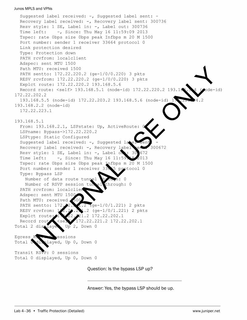
Junos MPLS and VPNs
Lab 4–36 • Traffic Protection (Detailed) www.juniper.net
Suggested label received: -, Suggested label sent: - Recovery label received: -, Recovery label sent: 300736 Resv style: 1 SE, Label in: -, Label out: 300736 Time left: -, Since: Thu May 16 11:59:09 2013 Tspec: rate 0bps size 0bps peak Infbps m 20 M 1500 Port number: sender 1 receiver 33664 protocol 0 Link protection desired Type: Protection down PATH rcvfrom: localclient Adspec: sent MTU 1500 Path MTU: received 1500 PATH sentto: 172.22.220.2 (ge-1/0/0.220) 3 pkts RESV rcvfrom: 172.22.220.2 (ge-1/0/0.220) 3 pkts Explct route: 172.22.220.2 193.168.5.6 Record route: <self> 193.168.5.1 (node-id) 172.22.220.2 193.168.5.4 (node-id) 172.22.202.2 193.168.5.5 (node-id) 172.22.203.2 193.168.5.6 (node-id) 172.22.204.2 193.168.2.2 (node-id) 172.22.223.1 193.168.5.1 From: 193.168.2.1, LSPstate: Up, ActiveRoute: 0 LSPname: Bypass->172.22.220.2 LSPtype: Static Configured Suggested label received: -, Suggested label sent: - Recovery label received: -, Recovery label sent: 300672 Resv style: 1 SE, Label in: -, Label out: 300672 Time left: -, Since: Thu May 16 11:59:18 2013 Tspec: rate 0bps size 0bps peak Infbps m 20 M 1500 Port number: sender 1 receiver 33665 protocol 0 Type: Bypass LSP Number of data route tunnel through: 0 Number of RSVP session tunnel through: 0 PATH rcvfrom: localclient Adspec: sent MTU 1500 Path MTU: received 1500 PATH sentto: 172.22.221.2 (ge-1/0/1.221) 2 pkts RESV rcvfrom: 172.22.221.2 (ge-1/0/1.221) 2 pkts Explct route: 172.22.221.2 172.22.202.1 Record route: <self> 172.22.221.2 172.22.202.1 Total 2 displayed, Up 2, Down 0
Egress RSVP: 0 sessions Total 0 displayed, Up 0, Down 0
Transit RSVP: 0 sessionsTotal 0 displayed, Up 0, Down 0
Question: Is the bypass LSP up?
Answer: Yes, the bypass LSP should be up.
INTERNAL U
SE ONLY

Junos MPLS and VPNs
www.juniper.net Traffic Protection (Detailed) • Lab 4–37
Question: Does the bypass LSP provide protection for the failure of the ge-1/0/0 link?
Answer: Yes. Use the record route information for the bypass LSP to determine the path of the bypass LSP.
Step 8.8 (Optional)
Enter configuration mode and disable the interface on your PE router that is used by the primary path of the LSP. Commit your configuration and exit to operational mode. Verify that protection occurs using the methods learned in this lab.
Part 9: Configuring LDP Link Protection
In this lab part, you will become familiar with an LDP LSP that is protected by link and protection.
Step 9.1
Enter configuration mode navigate to the [edit protocols mpls] hierarchy. Delete the LSP from the previous sections of the lab.
lab@mxB-1> configure Entering configuration mode
[edit]lab@mxB-1# edit protocols mpls
[edit protocols mpls]lab@mxB-1# delete label-switched-path localPE-to-remotePE-pod
[edit protocols mpls]lab@mxB-1#
Step 9.2
Navigate to the [edit protocols ldp] and enable LDP on every interface.
[edit protocols mpls]lab@mxB-1# top edit protocols ldp
[edit protocols ldp]lab@mxB-1# set interface all
[edit protocols ldp]lab@mxB-1# commit commit complete
[edit protocols ldp]lab@mxB-1#
INTERNAL U
SE ONLY

Junos MPLS and VPNs
Lab 4–38 • Traffic Protection (Detailed) www.juniper.net
Step 9.3
Use the show ldp interfaces command to determine if LDP has been enabled.
[edit protocols ldp]lab@mxB-1# run show ldp interface Interface Label space ID Nbr count Next hellolo0.0 193.168.2.1:0 0 0ge-1/0/0.220 193.168.2.1:0 1 0ge-1/0/1.221 193.168.2.1:0 1 2
Question: Does your router have any LDP neighbors? What interfaces?
Answer: Your PE router should have a single neighbor on each of the two core facing interfaces.
Step 9.4
Use the show route 193.168/16 command to view the routes to the loopback address of all routers in the topology.
[edit protocols ldp]lab@mxB-1# run show route 193.168/16
inet.0: 35 destinations, 35 routes (35 active, 0 holddown, 0 hidden)+ = Active Route, - = Last Active, * = Both
193.168.2.1/32 *[Direct/0] 08:46:49 > via lo0.0193.168.2.2/32 *[OSPF/10] 00:00:09, metric 4 > to 172.22.220.2 via ge-1/0/0.220 to 172.22.221.2 via ge-1/0/1.221193.168.5.1/32 *[OSPF/10] 00:00:09, metric 1 > to 172.22.220.2 via ge-1/0/0.220193.168.5.2/32 *[OSPF/10] 00:00:09, metric 2 > to 172.22.220.2 via ge-1/0/0.220193.168.5.3/32 *[OSPF/10] 00:00:09, metric 3 > to 172.22.220.2 via ge-1/0/0.220193.168.5.4/32 *[OSPF/10] 00:05:07, metric 1 > to 172.22.221.2 via ge-1/0/1.221193.168.5.5/32 *[OSPF/10] 00:05:07, metric 2 > to 172.22.221.2 via ge-1/0/1.221193.168.5.6/32 *[OSPF/10] 00:05:07, metric 3 > to 172.22.221.2 via ge-1/0/1.221
inet.3: 7 destinations, 7 routes (7 active, 0 holddown, 0 hidden)+ = Active Route, - = Last Active, * = Both
193.168.2.2/32 *[LDP/9] 00:00:09, metric 1 to 172.22.220.2 via ge-1/0/0.220, Push 300704 > to 172.22.221.2 via ge-1/0/1.221, Push 300592193.168.5.1/32 *[LDP/9] 00:00:09, metric 1
INTERNAL U
SE ONLY

Junos MPLS and VPNs
www.juniper.net Traffic Protection (Detailed) • Lab 4–39
> to 172.22.220.2 via ge-1/0/0.220193.168.5.2/32 *[LDP/9] 00:00:09, metric 1 > to 172.22.220.2 via ge-1/0/0.220, Push 299952193.168.5.3/32 *[LDP/9] 00:00:09, metric 1 > to 172.22.220.2 via ge-1/0/0.220, Push 299968193.168.5.4/32 *[LDP/9] 00:05:07, metric 1 > to 172.22.221.2 via ge-1/0/1.221193.168.5.5/32 *[LDP/9] 00:05:07, metric 1 > to 172.22.221.2 via ge-1/0/1.221, Push 299984193.168.5.6/32 *[LDP/9] 00:05:07, metric 1 > to 172.22.221.2 via ge-1/0/1.221, Push 300000
Question: Do you notice anything similar about the OSPF learned routes and the LDP learned routes?
Answer: For every OSPF learned route in inet.0 there is an equivalent LDP route in inet.3. Both sets of routes are also using the exact same next hops.
Question: How many next hops are associated with each route?
Answer: The route to each P router should have one next hop. The route to each PE router should have 2 next hops.
Step 9.5
Navigate to the [edit protocols ospf] hierarchy. On the ge-1/0/0.unit interface, apply link protection. Commit your configuration.
[edit protocols ldp]lab@mxB-1# top edit protocols ospf
[edit protocols ospf]lab@mxB-1# set area 0 interface ge-1/0/0.unit link-protection
[edit protocols ospf]lab@mxB-1# commit commit complete
[edit protocols ospf]lab@mxB-1#
Step 9.6
Use the show route 193.168/16 command to view the routes to the loopback address of all routers in the topology.
[edit protocols ospf]lab@mxB-1# run show route 193.168/16
INTERNAL U
SE ONLY

Junos MPLS and VPNs
Lab 4–40 • Traffic Protection (Detailed) www.juniper.net
inet.0: 35 destinations, 35 routes (35 active, 0 holddown, 0 hidden)+ = Active Route, - = Last Active, * = Both
193.168.2.1/32 *[Direct/0] 09:11:08 > via lo0.0193.168.2.2/32 *[OSPF/10] 00:01:45, metric 4 to 172.22.220.2 via ge-1/0/0.220 > to 172.22.221.2 via ge-1/0/1.221193.168.5.1/32 *[OSPF/10] 00:01:45, metric 1 > to 172.22.220.2 via ge-1/0/0.220 to 172.22.221.2 via ge-1/0/1.221193.168.5.2/32 *[OSPF/10] 00:01:45, metric 2 > to 172.22.220.2 via ge-1/0/0.220 to 172.22.221.2 via ge-1/0/1.221193.168.5.3/32 *[OSPF/10] 00:01:45, metric 3 > to 172.22.220.2 via ge-1/0/0.220 to 172.22.221.2 via ge-1/0/1.221193.168.5.4/32 *[OSPF/10] 00:29:26, metric 1 > to 172.22.221.2 via ge-1/0/1.221193.168.5.5/32 *[OSPF/10] 00:29:26, metric 2 > to 172.22.221.2 via ge-1/0/1.221193.168.5.6/32 *[OSPF/10] 00:29:26, metric 3 > to 172.22.221.2 via ge-1/0/1.221
inet.3: 7 destinations, 7 routes (7 active, 0 holddown, 0 hidden)+ = Active Route, - = Last Active, * = Both
193.168.2.2/32 *[LDP/9] 00:01:45, metric 1 > to 172.22.220.2 via ge-1/0/0.220, Push 300704 to 172.22.221.2 via ge-1/0/1.221, Push 300592193.168.5.1/32 *[LDP/9] 00:01:45, metric 1 > to 172.22.220.2 via ge-1/0/0.220 to 172.22.221.2 via ge-1/0/1.221, Push 300032193.168.5.2/32 *[LDP/9] 00:01:45, metric 1 > to 172.22.220.2 via ge-1/0/0.220, Push 299952 to 172.22.221.2 via ge-1/0/1.221, Push 300016193.168.5.3/32 *[LDP/9] 00:01:45, metric 1 > to 172.22.220.2 via ge-1/0/0.220, Push 299968 to 172.22.221.2 via ge-1/0/1.221, Push 300048193.168.5.4/32 *[LDP/9] 00:29:26, metric 1 > to 172.22.221.2 via ge-1/0/1.221193.168.5.5/32 *[LDP/9] 00:29:26, metric 1 > to 172.22.221.2 via ge-1/0/1.221, Push 299984193.168.5.6/32 *[LDP/9] 00:29:26, metric 1 > to 172.22.221.2 via ge-1/0/1.221, Push 300000
Question: How did the routing tables change by adding link protection to the OSPF interface?
Answer: For all routes that use the protected interface as a next hop, a second next hop has been added to the routing table.
INTERNAL U
SE ONLY

Junos MPLS and VPNs
www.juniper.net Traffic Protection (Detailed) • Lab 4–41
Question: Why did the next hops change for the LDP routes when link protection was only configured under OSPF?
Answer: LDP uses the routes learned by the internal gateway protocol (IGP) to determine its best path to each destination that it learns in the network.
Question: For the LDP routes, what type of LSP is being used to protect the interface?
Answer: The routing table shows that it will be an LDP LSP that will provide the protection if the protected interface fails.
Step 9.7
Navigate to the [edit protocols mpls] hierarchy. Configure a path called avoid-top that ensure that an LSP will not traverse the ge-1/0/0 interface.
[edit protocols ospf]lab@mxB-1# top edit protocols mpls
[edit protocols mpls]lab@mxB-1# set path avoid-top address strict
Step 9.8
Configure a no-cspf RSVP LSP called protect that terminates on the P router attached to your ge-1/0/0 interface. Apply the avoid-top path to the LSP. Also, ensure that it can be used as a backup path for both OSPF routes and LDP routes by configuring backup and ldp-tunneling.
[edit protocols mpls]lab@mxB-1# set label-switched-path protect to p-router-address
[edit protocols mpls]lab@mxB-1# set label-switched-path protect no-cspf
[edit protocols mpls]lab@mxB-1# set label-switched-path protect primary avoid-top
[edit protocols mpls]lab@mxB-1# set label-switched-path protect backup
[edit protocols mpls]lab@mxB-1# set label-switched-path protect ldp-tunneling
INTERNAL U
SE ONLY

Junos MPLS and VPNs
Lab 4–42 • Traffic Protection (Detailed) www.juniper.net
[edit protocols mpls]lab@mxB-1# commit and-quit commit completeExiting configuration mode
lab@mxB-1>
Step 9.9
Issue the show mpls lsp command to verify the status of the RSVP LSP.
lab@mxB-1> show mpls lsp Ingress LSP: 1 sessionsTo From State Rt P ActivePath LSPname193.168.5.1 193.168.2.1 Up 0 * avoid-top protectTotal 1 displayed, Up 1, Down 0
Egress LSP: 0 sessionsTotal 0 displayed, Up 0, Down 0
Transit LSP: 0 sessionsTotal 0 displayed, Up 0, Down 0
Question: Is the RSVP LSP in the up state?
Answer: The RSVP LSP should be in the up state.
Step 9.10
Use the show route 193.168/16 command to view the routes to the loopback address of all routers in the topology.
lab@mxB-1> show route 193.168/16
inet.0: 35 destinations, 35 routes (35 active, 0 holddown, 0 hidden)+ = Active Route, - = Last Active, * = Both
193.168.2.1/32 *[Direct/0] 09:37:28 > via lo0.0193.168.2.2/32 *[OSPF/10] 00:28:05, metric 4 to 172.22.220.2 via ge-1/0/0.220 > to 172.22.221.2 via ge-1/0/1.221193.168.5.1/32 *[OSPF/10] 00:19:19, metric 1 > to 172.22.220.2 via ge-1/0/0.220 to 172.22.221.2 via ge-1/0/1.221, label-switched-path protect193.168.5.2/32 *[OSPF/10] 00:19:19, metric 2 > to 172.22.220.2 via ge-1/0/0.220 to 172.22.221.2 via ge-1/0/1.221, label-switched-path protect193.168.5.3/32 *[OSPF/10] 00:19:19, metric 3 > to 172.22.220.2 via ge-1/0/0.220 to 172.22.221.2 via ge-1/0/1.221, label-switched-path protect
INTERNAL U
SE ONLY

Junos MPLS and VPNs
www.juniper.net Traffic Protection (Detailed) • Lab 4–43
193.168.5.4/32 *[OSPF/10] 00:55:46, metric 1 > to 172.22.221.2 via ge-1/0/1.221193.168.5.5/32 *[OSPF/10] 00:55:46, metric 2 > to 172.22.221.2 via ge-1/0/1.221193.168.5.6/32 *[OSPF/10] 00:55:46, metric 3 > to 172.22.221.2 via ge-1/0/1.221
inet.3: 7 destinations, 8 routes (7 active, 0 holddown, 0 hidden)+ = Active Route, - = Last Active, * = Both
193.168.2.2/32 *[LDP/9] 00:28:05, metric 1 > to 172.22.220.2 via ge-1/0/0.220, Push 300704 to 172.22.221.2 via ge-1/0/1.221, Push 300592193.168.5.1/32 *[RSVP/7/1] 00:19:19, metric 1 > to 172.22.221.2 via ge-1/0/1.221, label-switched-path protect [LDP/9] 00:19:19, metric 1 > to 172.22.220.2 via ge-1/0/0.220 to 172.22.221.2 via ge-1/0/1.221, label-switched-path protect193.168.5.2/32 *[LDP/9] 00:19:19, metric 1 > to 172.22.220.2 via ge-1/0/0.220, Push 299952 to 172.22.221.2 via ge-1/0/1.221, label-switched-path protect193.168.5.3/32 *[LDP/9] 00:19:19, metric 1 > to 172.22.220.2 via ge-1/0/0.220, Push 299968 to 172.22.221.2 via ge-1/0/1.221, label-switched-path protect193.168.5.4/32 *[LDP/9] 00:55:46, metric 1 > to 172.22.221.2 via ge-1/0/1.221193.168.5.5/32 *[LDP/9] 00:55:46, metric 1 > to 172.22.221.2 via ge-1/0/1.221, Push 299984193.168.5.6/32 *[LDP/9] 00:55:46, metric 1 > to 172.22.221.2 via ge-1/0/1.221, Push 300000
Question: How did the routing tables change by adding the RSVP LSP?
Answer: For most routes that use the protected interface as the primary next hop, the LSP has been added as a second next hop.
Question: Did the next hops for route to the remote PE change? Why?
Answer: The next hops associated with the route to the remote PE did not change because OSPF was able to calculate two equal cost paths to the remote PE. When there are more than one equal cost paths, link protection is not necessary.
INTERNAL U
SE ONLY

Junos MPLS and VPNs
Lab 4–44 • Traffic Protection (Detailed) www.juniper.net
Question: For the LDP routes, what type of LSP is being used to protect the interface?
Answer: The routing table shows that it will be an RSVP LSP that will provide the protection if the protected interface fails.
Step 9.11
Log out of your assigned device using the exit command.
lab@mxB-1> exit
mxB-1 (ttyu0)
login:
STOP Tell your instructor that you have completed this lab.
INTERNAL U
SE ONLY

Junos MPLS and VPNs
www.juniper.net Traffic Protection (Detailed) • Lab 4–45
INTERNAL U
SE ONLY

Junos MPLS and VPNs
Lab 4–46 • Traffic Protection (Detailed) www.juniper.net
INTERNAL U
SE ONLY

Junos MPLS and VPNs
www.juniper.net Traffic Protection (Detailed) • Lab 4–47
INTERNAL U
SE ONLY

Junos MPLS and VPNs
Lab 4–48 • Traffic Protection (Detailed) www.juniper.net
INTERNAL U
SE ONLY

www.juniper.net Fate Sharing (Detailed) • Lab 5–1
LabFate Sharing (Detailed)
Overview
In this lab, you will load a baseline multiprotocol label switching (MPLS) network. You will analyze the default fate sharing behavior of your Juniper router. You will then configure fate sharing so that you can avoid a single point of failure between the primary and secondary paths of an MPLS label switched path (LSP). Next, you will enable Shared Risk Link Group (SRLG) values in the network such the IGP can help improve the Junos operating system’s default fate sharing behavior. Finally, you will repurpose a set of SRLG values for use as extended admin groups.
The lab is available in two formats: a high-level format that is designed to make you think through each step and a detailed format that offers step-by-step instructions complete with sample output from most commands.
By completing this lab, you will perform the following tasks:
• Load a baseline network.
• Define an Resource Reservation Protocol (RSVP) signaled LSP to the remote provider edge (PE) router.
• Add primary/secondary path protection to an LSP.
• Analyze the default fate sharing behavior of you Juniper routers.
• Modify the fate sharing behavior of you Juniper router.
• Enable and analyze the use of SRLG values.
• Enable extended admin groups to be used for signaling MPLS LSPs.
INTERNAL U
SE ONLY

Junos MPLS and VPNs
Lab 5–2 • Fate Sharing (Detailed) www.juniper.net
Part 1: Creating the Baseline Network
In this lab part, you will create the baseline network for the lab. You will load a baseline configuration which will configure your router’s interfaces, six logical systems that represent the core network (p1, p2, p3, p4, pe2, and VS), and the Open Shortest Path First (OSPF) topology. Since the core network is already configured for you, you will only be responsible for configure pe1 (the default logical system). The loaded configuration will also enable RSVP and MPLS on the core-facing interfaces of the pe1 router.
Step 1.1
Ensure that you know to which device you are assigned. Check with your instructor if necessary.
Step 1.2
Consult the management network diagram, provided by your instructor, to determine your device’s management address.
Question: What is the management address assigned to your station?
Answer: The answer varies. The sample hostname and IP address used in the output examples in this lab are for mxB-1, which uses 10.210.15.3 as its management IP address. The actual management subnet varies between delivery environments.
Note
The instructor will tell you the nature of your access and will provide you with the necessary details to access your assigned device.
INTERNAL U
SE ONLY

Junos MPLS and VPNs
www.juniper.net Fate Sharing (Detailed) • Lab 5–3
Step 1.3
Access the CLI at your station using either the console, Telnet, or Secure Shell (SSH) as directed by your instructor. The following example shows simple Telnet access to mxB-1 using the Secure CRT program.
Step 1.4
Log in as user lab with the password supplied by your instructor. Enter configuration mode and load the reset configuration file jmv/lab5-start.config. Commit the configuration and return to operational mode.
mxB-1 (ttyp0)
login: labPassword:
--- JUNOS 12.3R2.5 built 2013-03-22 17:12:14 UTClab@mxB-1> configure Entering configuration mode
[edit]lab@mxB-1# load override jmv/lab5-start.config load complete
[edit]lab@mxB-1# commit and-quit commit completeExiting configuration mode
lab@mxB-1>
Step 1.5
Verify that your Open Shortest Path First (OSPF) neighbor relationships are up and operational.
INTERNAL U
SE ONLY

Junos MPLS and VPNs
Lab 5–4 • Fate Sharing (Detailed) www.juniper.net
lab@mxB-1> show ospf neighbor Address Interface State ID Pri Dead10.0.13.3 ge-1/0/5.100 Full 193.168.1.3 128 3610.0.14.4 ge-1/0/5.200 Full 193.168.1.4 128 3510.0.12.2 ge-1/0/6.100 Full 193.168.1.2 128 33
Question: What is the state of your PE router’s OSPF neighbors?
Answer: After a short time, the OSPF neighbors should attain the Full state.
Step 1.6
Use the show route command to verify that your PE router has learned routes to the loopback address of all of the core routers in the network.
lab@mxB-1> show route 193.168/16
inet.0: 19 destinations, 19 routes (19 active, 0 holddown, 0 hidden)+ = Active Route, - = Last Active, * = Both
193.168.1.1/32 *[Direct/0] 4d 01:10:17 > via lo0.0193.168.1.2/32 *[OSPF/10] 00:09:30, metric 1 > to 10.0.12.2 via ge-1/0/6.100193.168.1.3/32 *[OSPF/10] 00:09:29, metric 1 > to 10.0.13.3 via ge-1/0/5.100193.168.1.4/32 *[OSPF/10] 00:09:30, metric 1 > to 10.0.14.4 via ge-1/0/5.200193.168.1.5/32 *[OSPF/10] 00:08:47, metric 2 > to 10.0.12.2 via ge-1/0/6.100193.168.1.6/32 *[OSPF/10] 00:08:47, metric 2 to 10.0.13.3 via ge-1/0/5.100 > to 10.0.14.4 via ge-1/0/5.200
Question: Has your PE router learned a route to each of the core routers’ loopback addresses?
Answer: Yes, your router should have learned a route for every router in the network from the OSPF protocol.
INTERNAL U
SE ONLY

Junos MPLS and VPNs
www.juniper.net Fate Sharing (Detailed) • Lab 5–5
Question: From your pe1’s perspective what is the best path to take to get to pe2? Describe that path.
Answer: The output of the command shows that there are two equal cost paths to get to pe2 (193.168.1.6). The best path from pe1 to pe2 would be across the pe1-p2-pe2 links or the pe1-p3-pe2 links. Both paths traverse a common Ethernet switch.
Step 1.7
Using show commands, verify that the MPLS and RSVP are configured correctly on the core-facing interfaces.
lab@mxB-1> show mpls interface Interface State Administrative groups (x: extended)ge-1/0/5.100 Up <none>ge-1/0/5.200 Up <none>ge-1/0/6.100 Up <none>
lab@mxB-1> show rsvp interface RSVP interface: 3 active Active Subscr- Static Available Reserved HighwaterInterface State resv iption BW BW BW markge-1/0/5.100Up 0 100% 1000Mbps 1000Mbps 0bps 0bps ge-1/0/5.200Up 0 100% 1000Mbps 1000Mbps 0bps 0bps ge-1/0/6.100Up 0 100% 1000Mbps 1000Mbps 0bps 0bps
Question: Can your core-facing interfaces now support the transmission of MPLS packets?
Answer: The outputs of the two commands show that the two interfaces can now support the forwarding of MPLS packets.
INTERNAL U
SE ONLY

Junos MPLS and VPNs
Lab 5–6 • Fate Sharing (Detailed) www.juniper.net
Part 2: Creating an LSP to the Remote PE
In this lab part, you will create an RSVP-signaled LSP from pe1 to pe2. You will create two empty paths (no EROs or admin groups) called path1 and path2. You will apply path1 as the primary path of your LSP and path2 as the secondary path of your LSP while ensuring that the secondary LSP is in standby mode.
Step 2.1
Enter configuration mode and navigate to the [edit protocols mpls] hierarchy. Create two empty paths called path1 and path2.
lab@mxB-1> configure Entering configuration mode
[edit]lab@mxB-1# edit protocols mpls
[edit protocols mpls]lab@mxB-1# set path path1
[edit protocols mpls]lab@mxB-1# set path path2
[edit protocols mpls]lab@mxB-1#
Step 2.2
Configure an LSP named lsp1 from pe1 to pe2 with a primary path of path1 and a secondary path of path2. Ensure the secondary path is on standby. Your LSP should egress at pe2’s loopback address.
[edit protocols mpls]lab@mxB-1# set label-switched-path lsp1 to 193.168.1.6
[edit protocols mpls]lab@mxB-1# set label-switched-path lsp1 primary path1
[edit protocols mpls]lab@mxB-1# set label-switched-path lsp1 secondary path2 standby
Step 2.3
Enable traceoptions for MPLS by configuring a file name cspf-trace.log and specify the flags of cspf, cspf-link, and cspf-node. Commit your configuration and exit to operational mode.
[edit protocols mpls]lab@mxB-1# set traceoptions file cspf-trace.log
[edit protocols mpls]lab@mxB-1# set traceoptions flag cspf
[edit protocols mpls]lab@mxB-1# set traceoptions flag cspf-link
INTERNAL U
SE ONLY

Junos MPLS and VPNs
www.juniper.net Fate Sharing (Detailed) • Lab 5–7
[edit protocols mpls]lab@mxB-1# set traceoptions flag cspf-node
[edit protocols mpls]lab@mxB-1# commit and-quit commit completeExiting configuration mode
lab@mxB-1>
Step 2.4
Issue the show rsvp session ingress detail command to verify that the new LSPs are up and also determine the path that they are taking.
lab@mxB-1> show rsvp session ingress detail Ingress RSVP: 2 sessions
193.168.1.6 From: 193.168.1.1, LSPstate: Up, ActiveRoute: 0 LSPname: lsp1, LSPpath: Primary LSPtype: Static Configured Suggested label received: -, Suggested label sent: - Recovery label received: -, Recovery label sent: 299776 Resv style: 1 FF, Label in: -, Label out: 299776 Time left: -, Since: Mon Jun 3 15:03:49 2013 Tspec: rate 0bps size 0bps peak Infbps m 20 M 1500 Port number: sender 1 receiver 18433 protocol 0 PATH rcvfrom: localclient Adspec: sent MTU 1500 Path MTU: received 1500 PATH sentto: 10.0.13.3 (ge-1/0/5.100) 10 pkts RESV rcvfrom: 10.0.13.3 (ge-1/0/5.100) 9 pkts Explct route: 10.0.13.3 10.0.36.2 Record route: <self> 10.0.13.3 10.0.36.2
193.168.1.6 From: 193.168.1.1, LSPstate: Up, ActiveRoute: 0 LSPname: lsp1, LSPpath: Secondary LSPtype: Static Configured Suggested label received: -, Suggested label sent: - Recovery label received: -, Recovery label sent: 299776 Resv style: 1 FF, Label in: -, Label out: 299776 Time left: -, Since: Mon Jun 3 15:04:18 2013 Tspec: rate 0bps size 0bps peak Infbps m 20 M 1500 Port number: sender 2 receiver 18434 protocol 0 PATH rcvfrom: localclient Adspec: sent MTU 1500 Path MTU: received 1500 PATH sentto: 10.0.14.4 (ge-1/0/5.200) 9 pkts RESV rcvfrom: 10.0.14.4 (ge-1/0/5.200) 8 pkts Explct route: 10.0.14.4 10.0.46.2 Record route: <self> 10.0.14.4 10.0.46.2 Total 2 displayed, Up 2, Down 0
INTERNAL U
SE ONLY

Junos MPLS and VPNs
Lab 5–8 • Fate Sharing (Detailed) www.juniper.net
Question: Are the new LSPs up?
Answer: Yes, the LSPs should be up.
Question: What path are the LSPs taking through the network?
Answer: The answer will vary by student. In the example the primary LSP is traversing the pe1-p2-pe2 links while the secondary LSP is traversing the pe1-p3-pe2 links.
Question: Do the two LSPs have a potential single point of failure?
Answer: The LSPs both traverse the single Ethernet switch. This causes a single point of failure between the two LSPs.
Question: Why do you think that the primary and secondary LSPs do not take the exact same path?
Answer: The reason the LSPs do not traverse the exact same path is because of the Junos OS’s default fate sharing behavior. Prior to running the CSPF algorithm for the secondary LSP, the Junos OS will add 8000000 to the CSPF metric of the links traversed by the primary LSP.
Question: Why does the secondary path not take the pe1-p1-p4-pe2 links?
Answer: The reason the secondary path does not traverse the pe1-p1-p4-pe2 link is because the router has determined that it is not the shortest cost path to get to the pe2 router. That path has a cost of 3 while one of the other paths only has a cost of 2.
INTERNAL U
SE ONLY
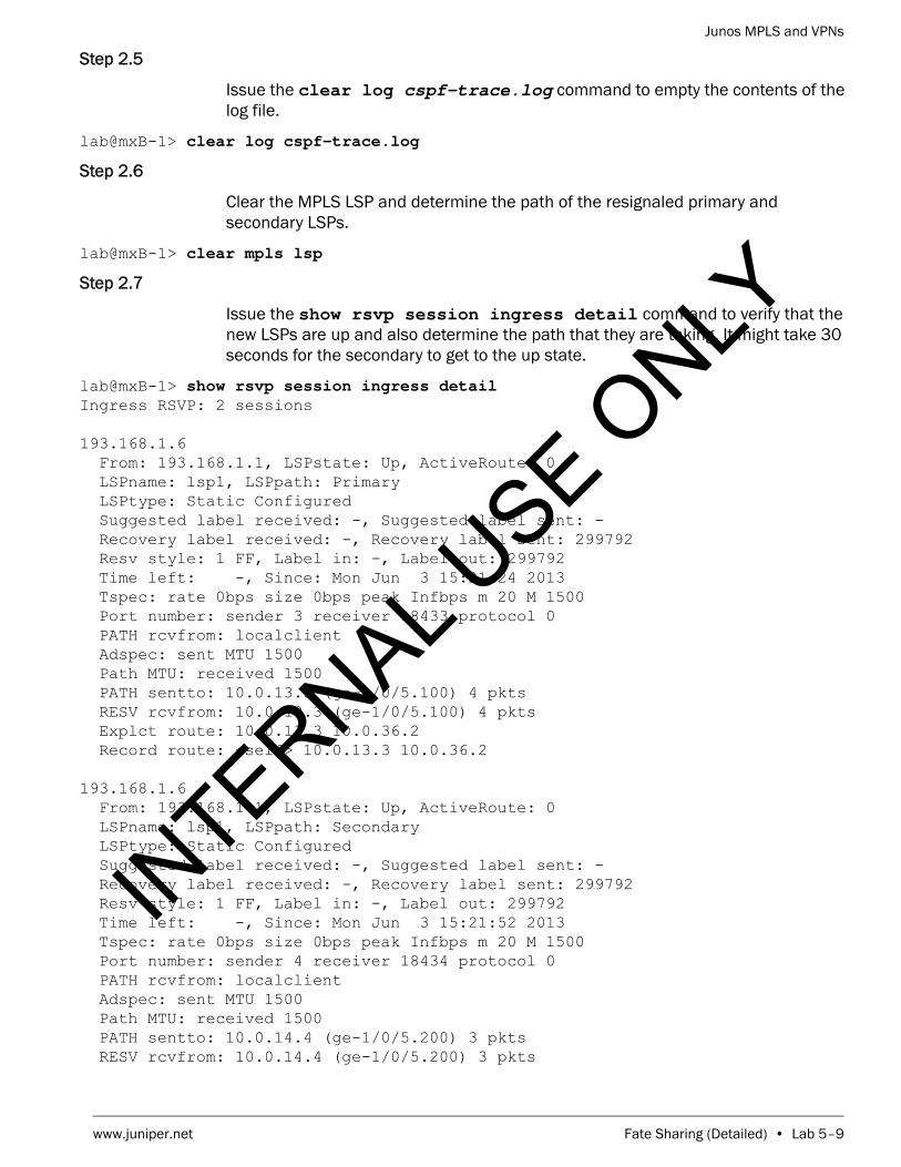
Junos MPLS and VPNs
www.juniper.net Fate Sharing (Detailed) • Lab 5–9
Step 2.5
Issue the clear log cspf-trace.log command to empty the contents of the log file.
lab@mxB-1> clear log cspf-trace.log
Step 2.6
Clear the MPLS LSP and determine the path of the resignaled primary and secondary LSPs.
lab@mxB-1> clear mpls lsp
Step 2.7
Issue the show rsvp session ingress detail command to verify that the new LSPs are up and also determine the path that they are taking. It might take 30 seconds for the secondary to get to the up state.
lab@mxB-1> show rsvp session ingress detail Ingress RSVP: 2 sessions
193.168.1.6 From: 193.168.1.1, LSPstate: Up, ActiveRoute: 0 LSPname: lsp1, LSPpath: Primary LSPtype: Static Configured Suggested label received: -, Suggested label sent: - Recovery label received: -, Recovery label sent: 299792 Resv style: 1 FF, Label in: -, Label out: 299792 Time left: -, Since: Mon Jun 3 15:21:24 2013 Tspec: rate 0bps size 0bps peak Infbps m 20 M 1500 Port number: sender 3 receiver 18433 protocol 0 PATH rcvfrom: localclient Adspec: sent MTU 1500 Path MTU: received 1500 PATH sentto: 10.0.13.3 (ge-1/0/5.100) 4 pkts RESV rcvfrom: 10.0.13.3 (ge-1/0/5.100) 4 pkts Explct route: 10.0.13.3 10.0.36.2 Record route: <self> 10.0.13.3 10.0.36.2
193.168.1.6 From: 193.168.1.1, LSPstate: Up, ActiveRoute: 0 LSPname: lsp1, LSPpath: Secondary LSPtype: Static Configured Suggested label received: -, Suggested label sent: - Recovery label received: -, Recovery label sent: 299792 Resv style: 1 FF, Label in: -, Label out: 299792 Time left: -, Since: Mon Jun 3 15:21:52 2013 Tspec: rate 0bps size 0bps peak Infbps m 20 M 1500 Port number: sender 4 receiver 18434 protocol 0 PATH rcvfrom: localclient Adspec: sent MTU 1500 Path MTU: received 1500 PATH sentto: 10.0.14.4 (ge-1/0/5.200) 3 pkts RESV rcvfrom: 10.0.14.4 (ge-1/0/5.200) 3 pkts
INTERNAL U
SE ONLY

Junos MPLS and VPNs
Lab 5–10 • Fate Sharing (Detailed) www.juniper.net
Explct route: 10.0.14.4 10.0.46.2 Record route: <self> 10.0.14.4 10.0.46.2 Total 2 displayed, Up 2, Down 0
Question: Are the new LSPs up?
Answer: Yes, the LSPs should be up.
Question: What path are the LSPs taking through the network?
Answer: The answer will vary by student. In the example the primary LSP is traversing the pe1-p2-pe2 links while the secondary LSP is traversing the pe1-p3-pe2 links.
Step 2.8
View the cspf-trace.log file to view the CSPF calculation of the secondary LSP.
lab@mxB-1> show log cspf-trace.log | find secondary Jun 3 15:21:52.857429 CSPF adding path lsp1(secondary path2) to CSPF queue 0Jun 3 15:21:52.857511 CSPF creating CSPF jobJun 3 15:21:52.857631Jun 3 15:21:52.857662 CSPF for path lsp1(secondary path2), begin at 0000.0000.0000.00 , startingJun 3 15:21:52.857699 path SRLG: Unknown-0x3e8 Unknown-0x64Jun 3 15:21:52.857745 bandwidth: CT0=0bps ; setup priority: 0; randomJun 3 15:21:52.857785 CSPF credibility 0Jun 3 15:21:52.857808 CSPF final destination 193.168.1.6Jun 3 15:21:52.857844 CSPF starting from 0000.0000.0000.00 (193.168.1.1) to 193.168.1.6, hoplimit 254Jun 3 15:21:52.857867 constraint avoid primary path...Jun 3 15:21:52.858809 Link 0.0.0.0->0.0.0.0(0000.0000.0000.00/193.168.1.3, Link IDs 0->0) metric 0 color 0x00000000 bw 0bpsJun 3 15:21:52.858839 Reverse Link for 0.0.0.0(10.0.13.1:0)->0.0.0.0(193.168.1.3:0) is 10.0.13.3(193.168.1.3:0)->0.0.0.0(10.0.13.1:0)Jun 3 15:21:52.858860 no constraints to checkJun 3 15:21:52.858883 Link overlap with primary path, adding cost 8000000...
INTERNAL U
SE ONLY

Junos MPLS and VPNs
www.juniper.net Fate Sharing (Detailed) • Lab 5–11
Question: Can you tell from the log file as to why the primary and secondary LSPs do not take the exact same path?
Answer: The reason the LSPs do not traverse the exact same path is because of the Junos OS’s default fate sharing behavior. As shown in the log output, prior to running the CSPF algorithm for the secondary LSP, the Junos OS adds 8000000 to the CSPF metric of the links traversed by the primary LSP.
Part 3: Configuring Fate Sharing
In this lab part, you will configure fate sharing so that the ingress router can attempt to avoid the single point of failure (the Ethernet switch) when signaling the secondary LSP.
Step 3.1
Enter configuration mode and navigate to the [edit routing-options] hierarchy. Configure a fate sharing group called switch. Configure fate sharing for that group such that a cost of 20000 will be added to all links associated with the Ethernet switch (in the event that the primary traverses the switch) prior to calculating the path of the secondary LSP. Commit your configuration and exit to operational mode.
lab@mxB-1> configure Entering configuration mode
[edit]lab@mxB-1# edit routing-options
[edit routing-options]lab@mxB-1# set fate-sharing group switch cost 20000
[edit routing-options]lab@mxB-1# set fate-sharing group switch from 10.0.14.1
[edit routing-options]lab@mxB-1# set fate-sharing group switch from 10.0.14.4
[edit routing-options]lab@mxB-1# set fate-sharing group switch from 10.0.13.1
[edit routing-options]lab@mxB-1# set fate-sharing group switch from 10.0.13.3
[edit routing-options]lab@mxB-1# commit and-quit
INTERNAL U
SE ONLY

Junos MPLS and VPNs
Lab 5–12 • Fate Sharing (Detailed) www.juniper.net
commit completeExiting configuration mode
lab@mxB-1>
Step 3.2
Issue the clear log cspf-trace.log command to empty the contents of the log file.
lab@mxB-1> clear log cspf-trace.log
Step 3.3
Clear the MPLS LSP and determine the path of the resignaled primary and secondary LSPs.
lab@mxB-1> clear mpls lsp
Step 3.4
Issue the show rsvp session ingress detail command to verify that the new LSPs are up and also determine the path that they are taking. It may take 30 seconds for the secondary to get to the up state.
lab@mxB-1> show rsvp session ingress detail Ingress RSVP: 2 sessions
193.168.1.6 From: 193.168.1.1, LSPstate: Up, ActiveRoute: 0 LSPname: lsp1, LSPpath: Primary LSPtype: Static Configured Suggested label received: -, Suggested label sent: - Recovery label received: -, Recovery label sent: 299808 Resv style: 1 FF, Label in: -, Label out: 299808 Time left: -, Since: Mon Jun 3 16:15:06 2013 Tspec: rate 0bps size 0bps peak Infbps m 20 M 1500 Port number: sender 5 receiver 18433 protocol 0 PATH rcvfrom: localclient Adspec: sent MTU 1500 Path MTU: received 1500 PATH sentto: 10.0.13.3 (ge-1/0/5.100) 3 pkts RESV rcvfrom: 10.0.13.3 (ge-1/0/5.100) 3 pkts Explct route: 10.0.13.3 10.0.36.2 Record route: <self> 10.0.13.3 10.0.36.2
193.168.1.6 From: 193.168.1.1, LSPstate: Up, ActiveRoute: 0 LSPname: lsp1, LSPpath: Secondary LSPtype: Static Configured Suggested label received: -, Suggested label sent: - Recovery label received: -, Recovery label sent: 299776 Resv style: 1 FF, Label in: -, Label out: 299776 Time left: -, Since: Mon Jun 3 16:15:36 2013 Tspec: rate 0bps size 0bps peak Infbps m 20 M 1500 Port number: sender 6 receiver 18434 protocol 0 PATH rcvfrom: localclient Adspec: sent MTU 1500
INTERNAL U
SE ONLY
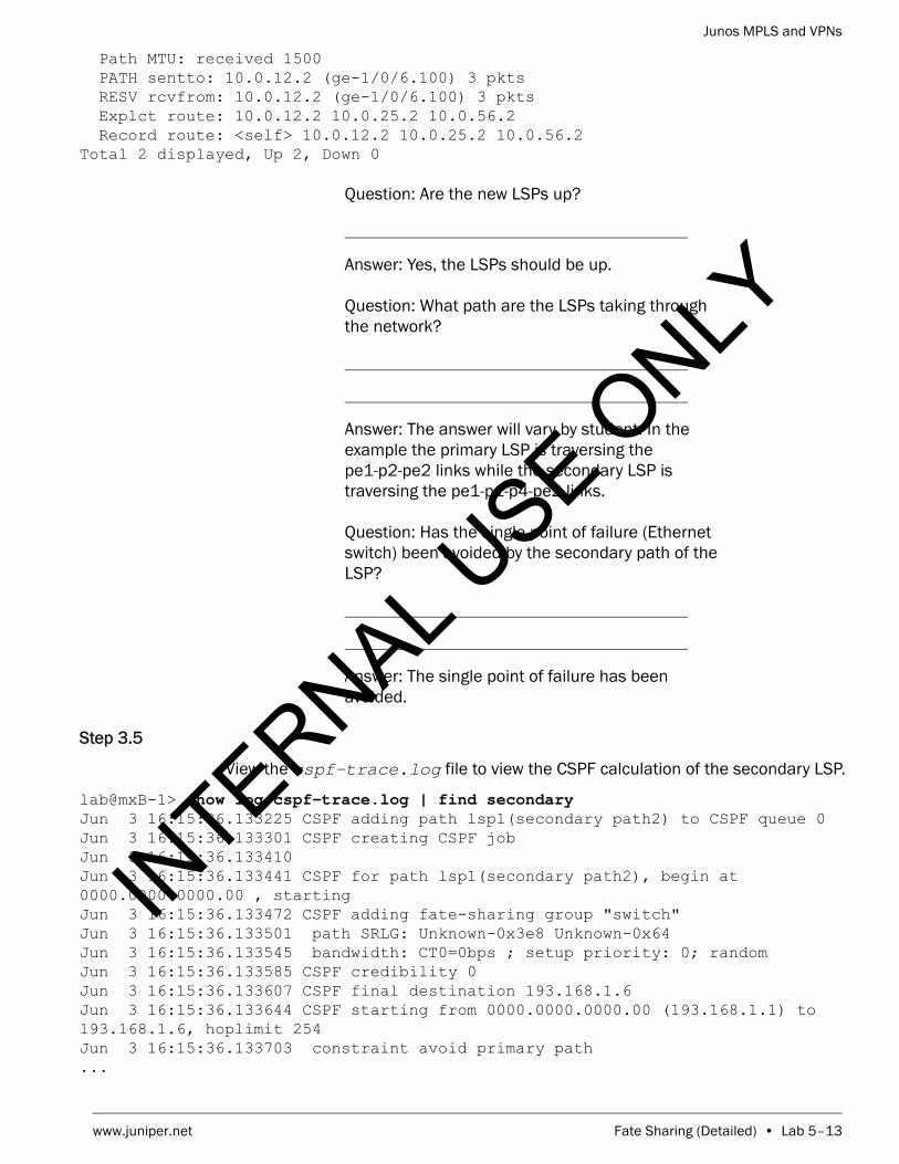
Junos MPLS and VPNs
www.juniper.net Fate Sharing (Detailed) • Lab 5–13
Path MTU: received 1500 PATH sentto: 10.0.12.2 (ge-1/0/6.100) 3 pkts RESV rcvfrom: 10.0.12.2 (ge-1/0/6.100) 3 pkts Explct route: 10.0.12.2 10.0.25.2 10.0.56.2 Record route: <self> 10.0.12.2 10.0.25.2 10.0.56.2 Total 2 displayed, Up 2, Down 0
Question: Are the new LSPs up?
Answer: Yes, the LSPs should be up.
Question: What path are the LSPs taking through the network?
Answer: The answer will vary by student. In the example the primary LSP is traversing the pe1-p2-pe2 links while the secondary LSP is traversing the pe1-p1-p4-pe2 links.
Question: Has the single point of failure (Ethernet switch) been avoided by the secondary path of the LSP?
Answer: The single point of failure has been avoided.
Step 3.5
View the cspf-trace.log file to view the CSPF calculation of the secondary LSP.
lab@mxB-1> show log cspf-trace.log | find secondary Jun 3 16:15:36.133225 CSPF adding path lsp1(secondary path2) to CSPF queue 0Jun 3 16:15:36.133301 CSPF creating CSPF jobJun 3 16:15:36.133410Jun 3 16:15:36.133441 CSPF for path lsp1(secondary path2), begin at 0000.0000.0000.00 , startingJun 3 16:15:36.133472 CSPF adding fate-sharing group "switch"Jun 3 16:15:36.133501 path SRLG: Unknown-0x3e8 Unknown-0x64Jun 3 16:15:36.133545 bandwidth: CT0=0bps ; setup priority: 0; randomJun 3 16:15:36.133585 CSPF credibility 0Jun 3 16:15:36.133607 CSPF final destination 193.168.1.6Jun 3 16:15:36.133644 CSPF starting from 0000.0000.0000.00 (193.168.1.1) to 193.168.1.6, hoplimit 254Jun 3 16:15:36.133703 constraint avoid primary path...
INTERNAL U
SE ONLY

Junos MPLS and VPNs
Lab 5–14 • Fate Sharing (Detailed) www.juniper.net
Jun 3 16:15:36.133906 fate-sharing "switch" detected while passing "10.0.14.1-1", adding cost 20000Jun 3 16:15:36.133929 Effective link metric 20001...Jun 3 16:15:36.134090 fate-sharing "switch" detected while passing "10.0.13.1-1", adding cost 20000Jun 3 16:15:36.134112 Effective link metric 20001Jun 3 16:15:36.134170 Link 10.0.12.1->0.0.0.0(0000.0000.0000.00/10.0.12.1, Link IDs 0->0) metric 1 color 0x00000000 bw 1000Mbps
Question: During the CSPF calculation of the secondary path, what is the CSPF metric being used for the pe1-p2 link as well as the pe1-p3 link?
Answer: The ingress router is adding 20000 to both links so the metric is 20001 for each link.
Part 4: Configuring SRLGs
In this lab part, you will configure an SRLG so that the ingress router can attempt to avoid the single point of failure (the Ethernet switch) when signaling the secondary LSP. Use the diagram labeled “Fate Sharing Lab - Part 4” for this part of the lab.
Step 4.1
Enter configuration mode and navigate to the [edit routing-options] hierarchy. Delete the entire configuration hierarchy at that level.
lab@mxB-1> configure Entering configuration mode
[edit]lab@mxB-1# edit routing-options
[edit routing-options]lab@mxB-1# delete Delete everything under this level? [yes,no] (no) yes
[edit routing-options]lab@mxB-1#
Step 4.2
Configure an SRLG called switch1. This SRLG should have a SRLG value of 1003 and an SRLG cost of 20000.
[edit routing-options]lab@mxB-1# set srlg switch1 srlg-value 1003
[edit routing-options]lab@mxB-1# set srlg switch1 srlg-cost 20000
INTERNAL U
SE ONLY

Junos MPLS and VPNs
www.juniper.net Fate Sharing (Detailed) • Lab 5–15
Step 4.3
Navigate to the [edit protocols mpls] hierarchy. Apply the switch1 SRLG to the two ge-1/0/5 subinterfaces that attach to the Ethernet switch. Commit your configuration and exit to operational mode.
[edit routing-options]lab@mxB-1# top edit protocols mpls
[edit protocols mpls]lab@mxB-1# set interface ge-1/0/5.100 srlg switch1
[edit protocols mpls]lab@mxB-1# set interface ge-1/0/5.200 srlg switch1
[edit protocols mpls]lab@mxB-1# commit and-quit commit completeExiting configuration mode
lab@mxB-1>
Step 4.4
Issue the clear log cspf-trace.log command to empty the contents of the log file.
lab@mxB-1> clear log cspf-trace.log
Step 4.5
Clear the MPLS LSP and determine the path of the resignaled primary and secondary LSPs.
lab@mxB-1> clear mpls lsp
Step 4.6
Issue the show rsvp session ingress detail command to verify that the new LSPs are up and also determine the path that they are taking. It may take 30 seconds for the secondary to get to the up state.
lab@mxB-1> show rsvp session ingress detail Ingress RSVP: 2 sessions
193.168.1.6 From: 193.168.1.1, LSPstate: Up, ActiveRoute: 0 LSPname: lsp1, LSPpath: Primary LSPtype: Static Configured Suggested label received: -, Suggested label sent: - Recovery label received: -, Recovery label sent: 299824 Resv style: 1 FF, Label in: -, Label out: 299824 Time left: -, Since: Mon Jun 3 17:04:31 2013 Tspec: rate 0bps size 0bps peak Infbps m 20 M 1500 Port number: sender 5 receiver 18435 protocol 0 PATH rcvfrom: localclient Adspec: sent MTU 1500 Path MTU: received 1500 PATH sentto: 10.0.14.4 (ge-1/0/5.200) 3 pkts
INTERNAL U
SE ONLY

Junos MPLS and VPNs
Lab 5–16 • Fate Sharing (Detailed) www.juniper.net
RESV rcvfrom: 10.0.14.4 (ge-1/0/5.200) 3 pkts Explct route: 10.0.14.4 10.0.46.2 Record route: <self> 10.0.14.4 10.0.46.2
193.168.1.6 From: 193.168.1.1, LSPstate: Up, ActiveRoute: 0 LSPname: lsp1, LSPpath: Secondary LSPtype: Static Configured Suggested label received: -, Suggested label sent: - Recovery label received: -, Recovery label sent: 299808 Resv style: 1 FF, Label in: -, Label out: 299808 Time left: -, Since: Mon Jun 3 17:05:01 2013 Tspec: rate 0bps size 0bps peak Infbps m 20 M 1500 Port number: sender 6 receiver 18436 protocol 0 PATH rcvfrom: localclient Adspec: sent MTU 1500 Path MTU: received 1500 PATH sentto: 10.0.12.2 (ge-1/0/6.100) 1 pkts RESV rcvfrom: 10.0.12.2 (ge-1/0/6.100) 1 pkts Explct route: 10.0.12.2 10.0.25.2 10.0.56.2 Record route: <self> 10.0.12.2 10.0.25.2 10.0.56.2 Total 2 displayed, Up 2, Down 0
Question: Are the new LSPs up?
Answer: Yes, the LSPs should be up.
Question: What path are the LSPs taking through the network?
Answer: The answer will vary by student. In the example the primary LSP is traversing the pe1-p3-pe2 links while the secondary LSP is traversing the pe1-p1-p4-pe2 links.
Question: Has the single point of failure (Ethernet switch) been avoided by the secondary path of the LSP?
Answer: The single point of failure has been avoided.
Step 4.7
View the cspf-trace.log file to view the CSPF calculation of the secondary LSP.
INTERNAL U
SE ONLY

Junos MPLS and VPNs
www.juniper.net Fate Sharing (Detailed) • Lab 5–17
lab@mxB-1> show log cspf-trace.log | find secondary Jun 3 17:05:01.198619 CSPF adding path lsp1(secondary path2) to CSPF queue 0Jun 3 17:05:01.198705 CSPF creating CSPF jobJun 3 17:05:01.198816Jun 3 17:05:01.198846 CSPF for path lsp1(secondary path2), begin at 0000.0000.0000.00 , startingJun 3 17:05:01.198883 path SRLG: switch1 Unknown-0x65Jun 3 17:05:01.198929 bandwidth: CT0=0bps ; setup priority: 0; randomJun 3 17:05:01.198969 CSPF credibility 0Jun 3 17:05:01.198992 CSPF final destination 193.168.1.6Jun 3 17:05:01.199028 CSPF starting from 0000.0000.0000.00 (193.168.1.1) to 193.168.1.6, hoplimit 254Jun 3 17:05:01.199088 constraint avoid primary pathJun 3 17:05:01.199114 Node 0000.0000.0000.00 (193.168.1.1) metric 0, hops 0, avail 32000 32000 32000 32000Jun 3 17:05:01.199158 Link 10.0.14.1->0.0.0.0(0000.0000.0000.00/10.0.14.1, Link IDs 0->0) metric 1 color 0x00000000 bw 1000MbpsJun 3 17:05:01.199192 Reverse Link for 10.0.14.1(193.168.1.1:0)->0.0.0.0(10.0.14.1:0) is 0.0.0.0(10.0.14.1:0)->0.0.0.0(193.168.1.1:0)Jun 3 17:05:01.199220 link's interface switch capability descriptor #1Jun 3 17:05:01.199243 encoding: Packet, switching: PacketJun 3 17:05:01.199264 link passes constraintsJun 3 17:05:01.199288 Effective link metric with SRLG: 20001Jun 3 17:05:01.199326 Link 10.0.13.1->0.0.0.0(0000.0000.0000.00/10.0.13.1, Link IDs 0->0) metric 1 color 0x00000000 bw 1000MbpsJun 3 17:05:01.199358 Reverse Link for 10.0.13.1(193.168.1.1:0)->0.0.0.0(10.0.13.1:0) is 0.0.0.0(10.0.13.1:0)->0.0.0.0(193.168.1.1:0)Jun 3 17:05:01.199382 link's interface switch capability descriptor #1Jun 3 17:05:01.199404 encoding: Packet, switching: PacketJun 3 17:05:01.199424 link passes constraintsJun 3 17:05:01.199446 Effective link metric with SRLG: 20001...
Question: During the CSPF calculation of the secondary path, what is the CSPF metric being used for the pe1-p2 link as well as the pe1-p3 link?
Answer: The ingress router is adding 20000 to both links so the metric is 20001 for each link.
Step 4.8
Issue to the show mpls lsp extensive command to determine the SRLGs that each path is currently traversing.
lab@mxB-1> show mpls lsp extensive Ingress LSP: 1 sessions
193.168.1.6 From: 193.168.1.1, State: Up, ActiveRoute: 0, LSPname: lsp1
INTERNAL U
SE ONLY
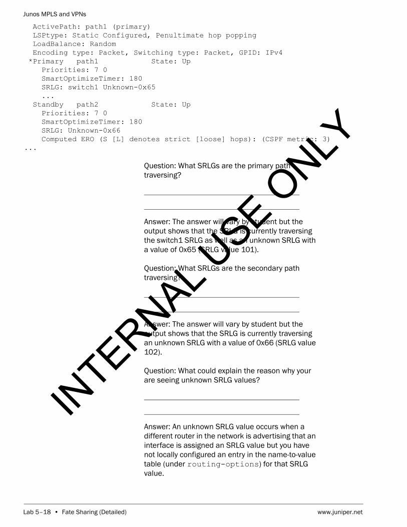
Junos MPLS and VPNs
Lab 5–18 • Fate Sharing (Detailed) www.juniper.net
ActivePath: path1 (primary) LSPtype: Static Configured, Penultimate hop popping LoadBalance: Random Encoding type: Packet, Switching type: Packet, GPID: IPv4 *Primary path1 State: Up Priorities: 7 0 SmartOptimizeTimer: 180 SRLG: switch1 Unknown-0x65 ... Standby path2 State: Up Priorities: 7 0 SmartOptimizeTimer: 180 SRLG: Unknown-0x66 Computed ERO (S [L] denotes strict [loose] hops): (CSPF metric: 3)...
Question: What SRLGs are the primary path traversing?
Answer: The answer will vary by student but the output shows that the SRLG is currently traversing the switch1 SRLG as well as an unknown SRLG with a value of 0x65 (SRLG value 101).
Question: What SRLGs are the secondary path traversing?
Answer: The answer will vary by student but the output shows that the SRLG is currently traversing an unknown SRLG with a value of 0x66 (SRLG value 102).
Question: What could explain the reason why your are seeing unknown SRLG values?
Answer: An unknown SRLG value occurs when a different router in the network is advertising that an interface is assigned an SRLG value but you have not locally configured an entry in the name-to-value table (under routing-options) for that SRLG value.
INTERNAL U
SE ONLY

Junos MPLS and VPNs
www.juniper.net Fate Sharing (Detailed) • Lab 5–19
Part 5: Configuring Extended Admin Groups
In this lab part, you will repurpose 100 SRLG values so that they can be used as extended admin groups. You will then configure an LSP that will traverse links that have been colored with extended admin groups.
Step 5.1
Enter configuration mode and navigate to the [edit routing-options] hierarchy. Configure the extended admin group range to be from 100 to 900.
lab@mxB-1> configure Entering configuration mode
[edit]lab@mxB-1# edit routing-options
[edit routing-options]lab@mxB-1# set admin-groups-extended-range minimum 100 maximum 900
[edit routing-options]lab@mxB-1#
Step 5.2
Configure 3 extended admin group called gold (value 100), silver (value 101), and bronze (value 102).
[edit routing-options]lab@mxB-1# set admin-groups-extended gold group-value 100
[edit routing-options]lab@mxB-1# set admin-groups-extended silver group-value 101
[edit routing-options]lab@mxB-1# set admin-groups-extended bronze group-value 102
Step 5.3
Navigate to the [edit protocols mpls] hierarchy and apply (color) the appropriate extended groups to your core facing interfaces.
[edit routing-options]lab@mxB-1# top edit protocols mpls
[edit protocols mpls]lab@mxB-1# set interface ge-1/0/5.100 admin-group-extended gold
[edit protocols mpls]lab@mxB-1# set interface ge-1/0/5.200 admin-group-extended silver
[edit protocols mpls]lab@mxB-1# set interface ge-1/0/6.100 admin-group-extended bronze
[edit protocols mpls]lab@mxB-1#
INTERNAL U
SE ONLY

Junos MPLS and VPNs
Lab 5–20 • Fate Sharing (Detailed) www.juniper.net
Step 5.4
Navigate to the [edit protocols mpls label-switched-path lsp-bronze] and configure an MPLS LSP named lsp-bronze. Ensure that it uses path1 as its primary path and that the LSP will only traverse links that are colored with the bronze extended admin group. The LSP should egress at the pe2 router. Commit your configuration and exit to operational mode.
[edit protocols mpls]lab@mxB-1# edit label-switched-path lsp-bronze
[edit protocols mpls label-switched-path lsp-bronze]lab@mxB-1# set to 193.168.1.6
[edit protocols mpls label-switched-path lsp-bronze]lab@mxB-1# set primary path1 admin-group-extended include-all bronze
[edit protocols mpls label-switched-path lsp-bronze]lab@mxB-1# commit and-quit commit completeExiting configuration mode
lab@mxB-1>
Step 5.5
Issue the show mpls interface command to verify that the extended admin groups have been applied properly to the pe1 router’s interfaces.
lab@mxB-1> show mpls interface Interface State Administrative groups (x: extended)ge-1/0/5.100 Up <none>gold(x)ge-1/0/5.200 Up <none>silver(x)ge-1/0/6.100 Up <none>bronze(x)
Question: Have the extended admin group been applied correctly to the pe1 router’s interfaces?
Answer: All interfaces should now show the appropriate extended admin groups.
Step 5.6
Issue to the show mpls lsp extensive name lsp-bronze command to determine the SRLGs that each path is currently traversing.
lab@mxB-1> show mpls lsp extensive name lsp-bronze Ingress LSP: 2 sessions
193.168.1.6 From: 193.168.1.1, State: Up, ActiveRoute: 0, LSPname: lsp-bronze ActivePath: path1 (primary) LSPtype: Static Configured, Penultimate hop popping LoadBalance: Random
INTERNAL U
SE ONLY

Junos MPLS and VPNs
www.juniper.net Fate Sharing (Detailed) • Lab 5–21
Encoding type: Packet, Switching type: Packet, GPID: IPv4 *Primary path1 State: Up Priorities: 7 0 SmartOptimizeTimer: 180 Extended Admin Group Include All: bronze Computed ERO (S [L] denotes strict [loose] hops): (CSPF metric: 3) 10.0.12.2 S 10.0.25.2 S 10.0.56.2 S Received RRO (ProtectionFlag 1=Available 2=InUse 4=B/W 8=Node 10=SoftPreempt 20=Node-ID): 10.0.12.2 10.0.25.2 10.0.56.2 6 Jun 3 18:21:45.462 Selected as active path 5 Jun 3 18:21:45.459 Record Route: 10.0.12.2 10.0.25.2 10.0.56.2 4 Jun 3 18:21:45.459 Up 3 Jun 3 18:21:45.435 Originate Call 2 Jun 3 18:21:45.435 CSPF: computation result accepted 10.0.12.2 10.0.25.2 10.0.56.2 1 Jun 3 18:21:16.000 CSPF failed: no route toward 193.168.1.6[40 times] Created: Mon Jun 3 18:02:50 2013Total 1 displayed, Up 1, Down 0
Egress LSP: 0 sessionsTotal 0 displayed, Up 0, Down 0
Transit LSP: 0 sessionsTotal 0 displayed, Up 0, Down 0
Question: What path is the lsp-bronze LSP taking to reach the pe2 router
Answer: The LSP should traverse the pe1-p1-p4-pe2 path.
Step 5.7
Log out of your assigned device using the exit command.
lab@mxB-1> exit
mxB-1 (ttyu0)
login:
STOP Tell your instructor that you have completed this lab.
INTERNAL U
SE ONLY

Junos MPLS and VPNs
Lab 5–22 • Fate Sharing (Detailed) www.juniper.net
INTERNAL U
SE ONLY

Junos MPLS and VPNs
www.juniper.net Fate Sharing (Detailed) • Lab 5–23
INTERNAL U
SE ONLY

Junos MPLS and VPNs
Lab 5–24 • Fate Sharing (Detailed) www.juniper.net
INTERNAL U
SE ONLY

Junos MPLS and VPNs
www.juniper.net Fate Sharing (Detailed) • Lab 5–25
INTERNAL U
SE ONLY

Junos MPLS and VPNs
Lab 5–26 • Fate Sharing (Detailed) www.juniper.net
INTERNAL U
SE ONLY

Junos MPLS and VPNs
www.juniper.net Fate Sharing (Detailed) • Lab 5–27
INTERNAL U
SE ONLY

Junos MPLS and VPNs
Lab 5–28 • Fate Sharing (Detailed) www.juniper.net
INTERNAL U
SE ONLY

www.juniper.net Miscellaneous MPLS Features (Detailed) • Lab 6–1
LabMiscellaneous MPLS Features (Detailed)
Overview
This lab demonstrates configuration and monitoring of miscellaneous Resource Reservation Protocol (RSVP) and Label Distribution Protocol (LDP) features on routers running the Junos operating system. In this lab, you use the command-line interface (CLI) to configure and monitor RSVP label-switched paths (LSPs) and enable miscellaneous features.
The lab is available in two formats: a high-level format designed to make you think through each step and a detailed format that offers step-by-step instructions complete with sample output from most commands.
By completing this lab, you will perform the following tasks:
• Configure an RSVP LSP to install a route in inet.0.
• Configure multiprotocol label switching (MPLS) traffic engineering to install a route in inet.0.
• Use policy to control LSP selection.
• Use metrics to control LSP selection.
• Configure the network to not decrement time-to-live (TTL).
• Configure a router to signal explicit null.
• Configure a router to automatically adjust the RSVP reservation based on observed bandwidth.
• Use MPLS pings to monitor connectivity.
INTERNAL U
SE ONLY

Junos MPLS and VPNs
Lab 6–2 • Miscellaneous MPLS Features (Detailed) www.juniper.net
Part 1: Configuring the Baseline Network
In this lab part, you will load a configuration that will automatically configure the interfaces and networks needed to establish an internal BGP (IBGP) peering between your provider edge (PE) router and the remote PE router. The loaded configuration will also enable RSVP and MPLS on the core-facing interfaces. After loading the configuration, you will configure an LSP to traverse the network to terminate at the remote provider edge (PE) router.
Step 1.1
Ensure that you know to which device you are assigned. Check with your instructor if necessary.
Step 1.2
Consult the management network diagram, provided by your instructor, to determine your device’s management address.
Question: What is the management address assigned to your station?
Answer: The answer varies. The sample hostname and IP address used in the output examples in this lab are for mxB-1, which uses 10.210.15.3 as its management IP address. The actual management subnet varies between delivery environments.
Note
The instructor will tell you the nature of your access and will provide you with the necessary details to access your assigned device.
INTERNAL U
SE ONLY

Junos MPLS and VPNs
www.juniper.net Miscellaneous MPLS Features (Detailed) • Lab 6–3
Step 1.3
Access the CLI at your station using either the console, Telnet, or Secure Shell (SSH) as directed by your instructor. The following example shows simple Telnet access to mxB-1 using the Secure CRT program.
Step 1.4
Log in as user lab with the password supplied by your instructor. Enter configuration mode and load the reset configuration file jmv/lab6-start.config. Commit the configuration and return to operational mode.
mxB-1 (ttyp0)
login: labPassword:
--- JUNOS 12.3R2.5 built 2013-03-22 17:12:14 UTClab@mxB-1> configure Entering configuration mode
[edit]lab@mxB-1# load override jmv/lab6-start.config load complete
[edit]lab@mxB-1# commit and-quit commit completeExiting configuration mode
lab@mxB-1>
Step 1.5
Verify that your Open Shortest Path First (OSPF) neighbor relationships are up and operational.
INTERNAL U
SE ONLY

Junos MPLS and VPNs
Lab 6–4 • Miscellaneous MPLS Features (Detailed) www.juniper.net
lab@mxB-1> show ospf neighbor Address Interface State ID Pri Dead172.22.220.2 ge-1/0/0.220 Full 193.168.5.1 128 34172.22.221.2 ge-1/0/1.221 Full 193.168.5.4 128 39
Question: What is the state of your PE router’s OSPF neighbors?
Answer: After a short time, the OSPF neighbors should attain the Full state.
Step 1.6
Verify that your PE router has established an IBGP neighbor relationship with the remote PE router.
lab@mxB-1> show bgp neighborPeer: 193.168.2.2+53868 AS 65512 Local: 193.168.2.1+179 AS 65512 Type: Internal State: Established Flags: <Sync> Last State: OpenConfirm Last Event: RecvKeepAlive Last Error: Cease Options: <Preference LocalAddress Refresh> Local Address: 193.168.2.1 Holdtime: 90 Preference: 170 Number of flaps: 2 Last flap event: Stop Error: 'Hold Timer Expired Error' Sent: 1 Recv: 0 Error: 'Cease' Sent: 2 Recv: 0 Peer ID: 193.168.2.2 Local ID: 193.168.2.1 Active Holdtime: 90 Keepalive Interval: 30 Group index: 0 Peer index: 0 BFD: disabled, down NLRI for restart configured on peer: inet-unicast NLRI advertised by peer: inet-unicast NLRI for this session: inet-unicast Peer supports Refresh capability (2) Stale routes from peer are kept for: 300 Peer does not support Restarter functionality NLRI that restart is negotiated for: inet-unicast NLRI of received end-of-rib markers: inet-unicast NLRI of all end-of-rib markers sent: inet-unicast Peer supports 4 byte AS extension (peer-as 65512) Peer does not support Addpath Table inet.0 Bit: 10000 RIB State: BGP restart is complete Send state: in sync Active prefixes: 1 Received prefixes: 1 Accepted prefixes: 1 Suppressed due to damping: 0 Advertised prefixes: 0
INTERNAL U
SE ONLY

Junos MPLS and VPNs
www.juniper.net Miscellaneous MPLS Features (Detailed) • Lab 6–5
Last traffic (seconds): Received 6 Sent 6 Checked 6 Input messages: Total 4 Updates 2 Refreshes 0 Octets 149 Output messages: Total 3 Updates 0 Refreshes 0 Octets 120 Output Queue[0]: 0
Question: Is the neighbor relationship in the established state with the remote PE router?
Answer: The remote PE router should be in an established state with your PE router. If it is not, double check the interface and BGP settings. If you need further assistance, consult with your instructor.
Step 1.7
Using show commands, verify that the MPLS and RSVP are configured correctly on the core-facing interfaces.
lab@mxB-1> show mpls interface Interface State Administrative groups (x: extended)ge-1/0/0.220 Up <none>ge-1/0/1.221 Up <none>
lab@mxB-1> show rsvp interface RSVP interface: 2 active Active Subscr- Static Available Reserved HighwaterInterface State resv iption BW BW BW markge-1/0/0.220Up 0 100% 1000Mbps 1000Mbps 0bps 0bps ge-1/0/1.221Up 0 100% 1000Mbps 1000Mbps 0bps 0bps
Question: Can your core-facing interfaces now support the transmission of MPLS packets?
Answer: The outputs of the two commands show that the two interfaces can now support the forwarding of MPLS packets.
Step 1.8
Add the configuration for creating a RSVP LSP to the remote PE router. Navigate to the [edit protocols mpls] hierarchy and create a LSP named localPE-to-remotePE-pod. For example, if you are assigned router mxB-1, your peer router is mxB-2 and your pod is B. The LSP for mxB-1 should be named pe1-to-pe2-B. Your LSP should egress at your remote peer’s loopback address. Verify the configuration looks correct. Commit and exit to operation mode when you are satisfied with the changes.
INTERNAL U
SE ONLY

Junos MPLS and VPNs
Lab 6–6 • Miscellaneous MPLS Features (Detailed) www.juniper.net
lab@mxB-1> configure Entering configuration mode
[edit]lab@mxB-1# edit protocols mpls
[edit protocols mpls]lab@mxB-1# set label-switched-path localPE-to-remotePE-pod to remote-pe-loopback-address
[edit protocols mpls]lab@mxB-1# show label-switched-path pe1-to-pe2-B { to 193.168.2.2;}interface ge-1/0/0.220;interface ge-1/0/1.221;interface lo0.0;
[edit protocols mpls]lab@mxB-1# commit and-quit commit completeExiting configuration mode
lab@mxB-1>
Step 1.9
Verify the status of your recently configured LSP reviewing the information displayed by issuing the show mpls lsp command.
lab@mxB-1> show mpls lsp Ingress LSP: 1 sessionsTo From State Rt P ActivePath LSPname193.168.2.2 193.168.2.1 Up 0 * pe1-to-pe2-BTotal 1 displayed, Up 1, Down 0
Egress LSP: 1 sessionsTo From State Rt Style Labelin Labelout LSPname 193.168.2.1 193.168.2.2 Up 0 1 FF 3 - pe2-to-pe1-BTotal 1 displayed, Up 1, Down 0
Transit LSP: 0 sessionsTotal 0 displayed, Up 0, Down 0
INTERNAL U
SE ONLY

Junos MPLS and VPNs
www.juniper.net Miscellaneous MPLS Features (Detailed) • Lab 6–7
Question: How many LSPs are reflected in the output and what are the terminating points?
Answer: If the remote team has finished configuring their LSP, you should see two LSPs. The LSP you configured should be displayed under the Ingress section and the other should be displayed under the Egress section. If the remote team has not finished their configuration you will only see the entry under the Ingress section. The terminating points of both LSP should be the loopback address of the ingress and egress routers.
STOP Do not proceed until the remote team finishes Part 1.
Part 2: Configuring a RSVP LSP to Install a Route in the inet.0 Table
In this lab part, you will add another interface to the OSPF network. Including the new interface in OSPF will allow you to establish reachability for the remote team. After establishing reachability, you will configure the router to install the remote team’s route as a destination that will use the established LSP for all traffic to the new network.
Step 2.1
Enter configuration mode and navigate to the [edit protocols ospf area 0.0.0.0] hierarchy and add the new interface to the existing configuration as a passive interface. We are adding the interface as passive because we are adding the interface for demonstrative purposes and will not be establishing a neighbor relationship on that interface. After you are satisfied with the changes, commit and exit to operational mode.
lab@mxB-1> configure Entering configuration mode
[edit]lab@mxB-1# edit protocols ospf area 0
[edit protocols ospf area 0.0.0.0]lab@mxB-1# set interface ge-1/0/4 passive
[edit protocols ospf area 0.0.0.0]lab@mxB-1# commit and-quit commit completeExiting configuration mode
lab@mxB-1>
INTERNAL U
SE ONLY

Junos MPLS and VPNs
Lab 6–8 • Miscellaneous MPLS Features (Detailed) www.juniper.net
Step 2.2
Use the show ospf interface command to verify the new interface is participating in your OSPF network.
lab@mxB-1> show ospf interface Interface State Area DR ID BDR ID Nbrsge-1/0/0.230 BDR 0.0.0.0 193.168.5.1 193.168.3.1 1ge-1/0/1.231 BDR 0.0.0.0 193.168.5.4 193.168.3.1 1ge-1/0/4.0 DRother 0.0.0.0 0.0.0.0 0.0.0.0 0lo0.0 DR 0.0.0.0 193.168.3.1 0.0.0.0 0
Question: Does the ge-1/0/4 interface appear as an OSPF interface in the output of the command?
Answer: The interface should appear as an OSPF interface.
Step 2.3
Verify with your remote team that they have completed the previous task. Once they have completed these steps, you will verify that you are receiving the new remote network as an OSPF route.
lab@mxB-1> show route remote-network/24
inet.0: 37 destinations, 37 routes (37 active, 0 holddown, 0 hidden)+ = Active Route, - = Last Active, * = Both
10.0.21.0/24 *[OSPF/10] 00:00:15, metric 5 > to 172.22.220.2 via ge-1/0/0.220 to 172.22.221.2 via ge-1/0/1.221
Question: Do you have the remote network in your routing table?
Answer: Yes, you should see the remote network in your routing table as an OSPF route. If you do not see the route, verify with your remote team that they have added the interface correctly. If you are having difficulty request assistance from your instructor.
Step 2.4
Enter into configuration mode and navigate to the [edit protocols mpls label-switched-path localPE-to-remotePE-pod] hierarchy. Using the install statement, add the remote network to your inet.3 routing table. Commit your changes.
lab@mxB-1> configure Entering configuration mode
INTERNAL U
SE ONLY

Junos MPLS and VPNs
www.juniper.net Miscellaneous MPLS Features (Detailed) • Lab 6–9
[edit]lab@mxB-1# edit protocols mpls label-switched-path localPE-to-remotePE-pod
[edit protocols mpls label-switched-path pe1-to-pe2-B]lab@mxB-1# set install remote-network/24
[edit protocols mpls label-switched-path pe1-to-pe2-B]lab@mxB-1# commit commit complete
[edit protocols mpls label-switched-path pe1-to-pe2-B]lab@mxB-1#
Step 2.5
Verify that the route has been added to the inet.3 routing table and points to the correct LSP.
[edit protocols mpls label-switched-path pe1-to-pe2-B]lab@mxB-1# run show route table inet.3
inet.3: 2 destinations, 2 routes (2 active, 0 holddown, 0 hidden)+ = Active Route, - = Last Active, * = Both
10.0.21.0/24 *[RSVP/7/1] 00:02:17, metric 4 > to 172.22.220.2 via ge-1/0/0.220, label-switched-path pe1-to-pe2-B193.168.2.2/32 *[RSVP/7/1] 00:02:17, metric 4 > to 172.22.220.2 via ge-1/0/0.220, label-switched-path pe1-to-pe2-B
Question: Do you see the route in your inet.3 routing table?
Answer: You should see the route in the table and it should be pointing to the LSP you installed it for. If you do not see the route review your configuration and contact the instructor as necessary.
Step 2.6
View the new route to determine if your router is using the OSPF route or the RSVP route for internal traffic. Remember that only BGP traffic can use the contents of the inet.3 routing table to resolve the BGP next hop and internal IPv4 traffic will only use the next hop found in the inet.0 routing table.
[edit protocols mpls label-switched-path pe1-to-pe2-B]lab@mxB-1# run show route remote-network/24
inet.0: 37 destinations, 37 routes (37 active, 0 holddown, 0 hidden)+ = Active Route, - = Last Active, * = Both
INTERNAL U
SE ONLY

Junos MPLS and VPNs
Lab 6–10 • Miscellaneous MPLS Features (Detailed) www.juniper.net
10.0.21.0/24 *[OSPF/10] 00:10:05, metric 5 > to 172.22.220.2 via ge-1/0/0.220 to 172.22.221.2 via ge-1/0/1.221
inet.3: 2 destinations, 2 routes (2 active, 0 holddown, 0 hidden)+ = Active Route, - = Last Active, * = Both
10.0.21.0/24 *[RSVP/7/1] 00:05:47, metric 4 > to 172.22.220.2 via ge-1/0/0.220, label-switched-path pe1-to-pe2-B
Question: Is your internal traffic going to use the OSPF route or the RSVP route?
Answer: Your internal traffic is going to use the OSPF route when resolving the next hop. The RSVP route is only installed in the inet.3 routing table. Internal traffic does not have access to the inet.3 routing table for next-hop resolution.
Step 2.7
Include the RSVP route in the inet.0 routing table, so that internal traffic can also use the LSP. Include this route by adding the active option to the route you installed under the LSP. After adding this option, commit your configuration,
[edit protocols mpls label-switched-path pe1-to-pe2-B]lab@mxB-1# set install remote-network/24 active
[edit protocols mpls label-switched-path pe1-to-pe2-B]lab@mxB-1# commitcommit complete
[edit protocols mpls label-switched-path pe1-to-pe2-B]lab@mxB-1
Step 2.8
Verify that you can now see the RSVP route in your inet.0 routing table.
[edit protocols mpls label-switched-path pe1-to-pe2-B]lab@mxB-1 run show route remote-network/24
inet.0: 37 destinations, 38 routes (37 active, 0 holddown, 0 hidden)+ = Active Route, - = Last Active, * = Both
10.0.21.0/24 *[RSVP/7/1] 00:01:38, metric 4 > to 172.22.220.2 via ge-1/0/0.220, label-switched-path pe1-to-pe2-B [OSPF/10] 00:13:36, metric 5 > to 172.22.220.2 via ge-1/0/0.220 to 172.22.221.2 via ge-1/0/1.221
INTERNAL U
SE ONLY

Junos MPLS and VPNs
www.juniper.net Miscellaneous MPLS Features (Detailed) • Lab 6–11
Question: Do you see the RSVP route in your inet.0 routing table?
Answer: Yes, you should now see that you have a RSVP route installed in your inet.0 routing table that points to your LSP. If you do not see the RSVP route, review your configuration and contact your instructor as needed.
Question: Which route will be used when resolving internal traffic?
Answer: Internal traffic will use the RSVP route to resolve next hops.
Question: Which route will be used when resolving external traffic (BGP) next hops?
Answer: External traffic will use the RSVP route.
Part 3: Configuring MPLS Traffic Engineering to Install an inet.0 Route
In this lab part, you will configure MPLS traffic engineering to move routes from inet.3 into the inet.0 routing table for both BGP and internal gateway protocol (IGP) routes. You will then use the traceroute utility to verify that the traffic is using the LSP for internal traffic.
Step 3.1
Remove the active option from the installed route. Review your configuration change before proceeding. When you are satisfied with the change, issue a commit and exit to operational mode.
[edit protocols mpls label-switched-path pe1-to-pe2-B]lab@mxB-1 show to 193.168.2.2;install 10.0.21.0/24 active;
[edit protocols mpls label-switched-path pe1-to-pe2-B]lab@mxB-1# delete install remote-network/24 active
[edit protocols mpls label-switched-path pe1-to-pe2-B]lab@mxB-1# show to 193.168.2.2;install 10.0.21.0/24;
INTERNAL U
SE ONLY

Junos MPLS and VPNs
Lab 6–12 • Miscellaneous MPLS Features (Detailed) www.juniper.net
[edit protocols mpls label-switched-path pe1-to-pe2-B]lab@mxB-1# commit and-quit commit completeExiting configuration mode
lab@mxB-1>
Step 3.2
Verify that you no longer have the RSVP route in your inet.0 routing table.
lab@mxB-1> show route remote-network/24
inet.0: 37 destinations, 37 routes (37 active, 0 holddown, 0 hidden)+ = Active Route, - = Last Active, * = Both
10.0.21.0/24 *[OSPF/10] 00:20:56, metric 5 > to 172.22.220.2 via ge-1/0/0.220 to 172.22.221.2 via ge-1/0/1.221
inet.3: 2 destinations, 2 routes (2 active, 0 holddown, 0 hidden)+ = Active Route, - = Last Active, * = Both
10.0.21.0/24 *[RSVP/7/1] 00:02:39, metric 4 > to 172.22.221.2 via ge-1/0/1.221, label-switched-path pe1-to-pe2-B
Question: Which protocol is being used in the inet.0 routing table?
Answer: The OSPF route should be the only route in the inet.0 routing table. If you still see the RSVP route, review your LSP configuration. If you are still having problems, contact your instructor for assistance.
Step 3.3
Enter into configuration mode and navigate to the [edit protocols mpls] hierarchy and enable traffic engineering to move routes from inet.3 into the inet.0 routing table for both BGP and IGP routes. Commit your configuration changes and exit out of configuration mode.
lab@mxB-1> configure Entering configuration mode
[edit]lab@mxB-1# edit protocols mpls
[edit protocols mpls]lab@mxB-1# set traffic-engineering ?Possible completions:
INTERNAL U
SE ONLY

Junos MPLS and VPNs
www.juniper.net Miscellaneous MPLS Features (Detailed) • Lab 6–13
bgp BGP destinations only bgp-igp BGP and IGP destinations bgp-igp-both-ribs BGP and IGP destinations with routes in both routing tables mpls-forwarding Use MPLS routes for forwarding, not routing[edit protocols mpls]lab@mxB-1# set traffic-engineering bgp-igp
[edit protocols mpls]lab@mxB-1# commit and-quit commit completeExiting configuration mode
lab@mxB-1>
Step 3.4
Verify that your inet.0 route table contains the RSVP route to the remote network specified to use the LSP.
lab@mxB-1> show route remote-network/24
inet.0: 37 destinations, 39 routes (37 active, 0 holddown, 0 hidden)+ = Active Route, - = Last Active, * = Both
10.0.21.0/24 *[RSVP/7/1] 00:01:04, metric 4 > to 172.22.220.2 via ge-1/0/0.220, label-switched-path pe1-to-pe2-B [OSPF/10] 00:01:09, metric 5 > to 172.22.220.2 via ge-1/0/0.220 to 172.22.221.2 via ge-1/0/1.221
Step 3.5
Using the traceroute utility verify that internal traffic will use the LSP when sending traffic to the remote network (use the address on the remote PE router’s ge-1/0/4 interface as a destination).
lab@mxB-1> traceroute remote-ge-1/0/4-address traceroute to 10.0.21.1 (10.0.21.1), 30 hops max, 40 byte packets 1 172.22.220.2 (172.22.220.2) 2.693 ms 0.617 ms 0.547 ms MPLS Label=300928 CoS=0 TTL=1 S=1 2 172.22.201.2 (172.22.201.2) 0.571 ms 0.595 ms 0.573 ms MPLS Label=300816 CoS=0 TTL=1 S=1 3 172.22.206.2 (172.22.206.2) 0.605 ms 0.609 ms 0.579 ms MPLS Label=300848 CoS=0 TTL=1 S=1 4 10.0.21.1 (10.0.21.1) 0.650 ms 0.568 ms 0.540 ms
Question: Does your traceroute complete?
Answer: Yes, your should see the traceroute responses from all routers along the path.
INTERNAL U
SE ONLY

Junos MPLS and VPNs
Lab 6–14 • Miscellaneous MPLS Features (Detailed) www.juniper.net
Question: Do you see MPLS label values associated with the traceroute responses?
Answer: Yes, you should see MPLS label values. If you do not, please review your configuration and request assistance from your instructor as needed.
Part 4: Using Policy to Control LSP Selection
In this lab part, you will use policy to control which LSP certain traffic traverses. You will begin by disabling the extra interface from OSPF that was added in Part 2. You will create two new LSPs that take different paths through the core network. You will then create two static routes and export these routes to your BGP peer. Finally, you will create and apply a policy to send traffic destined to the two routes—received from your neighbor—down separate LSPs.
Step 4.1
Enter into configuration mode and begin by removing the ge-1/0/4 interface that we added to OSPF area 0 in Part 2. You only need to remove this interface from your OSPF configuration.
lab@mxB-1> configure Entering configuration mode
[edit]lab@mxB-1# delete protocols ospf area 0 interface ge-1/0/4
Step 4.2
Navigate to the [edit protocols mpls] hierarchy and delete the existing label switched path and traffic engineering configuration.
[edit]lab@mxB-1# edit protocols mpls
[edit protocols mpls]lab@mxB-1# delete label-switched-path localPE-to-remotePE-pod
[edit protocols mpls]lab@mxB-1# delete traffic-engineering
[edit protocols mpls]lab@mxB-1#
Step 4.3
Create two paths named one and two. Specify the different loose hops that each LSP path should signal along. Path one should traverse the top of the network using the P1, P2, and P3 routers. Path two should traverse the bottom using P4, P5, and P6 routers.
INTERNAL U
SE ONLY

Junos MPLS and VPNs
www.juniper.net Miscellaneous MPLS Features (Detailed) • Lab 6–15
[edit protocols mpls]lab@mxB-1# set path one p-router-address loose
[edit protocols mpls]lab@mxB-1# set path one p-router-address loose
[edit protocols mpls]lab@mxB-1# set path one p-router-address loose
[edit protocols mpls]lab@mxB-1# set path two p-router-address loose
[edit protocols mpls]lab@mxB-1# set path two p-router-address loose
[edit protocols mpls]lab@mxB-1# set path two p-router-address loose
[edit protocols mpls]lab@mxB-1# show path one { 193.168.5.1 loose; 193.168.5.2 loose; 193.168.5.3 loose;}path two { 193.168.5.4 loose; 193.168.5.5 loose; 193.168.5.6 loose;}interface ge-1/0/0.220;interface ge-1/0/1.221;interface lo0.0;
Step 4.4
Create two label switched paths named lsp-1 and lsp-2. Apply path one to lsp-1 as the primary path and apply path two to lsp-2 as the primary path. Both LSPs should terminate at the remote PE router’s loopback. Before committing your configuration changes, review the changes. After you are satisfied with the changes commit and exit to operational mode.
[edit protocols mpls]lab@mxB-1# set label-switched-path lsp-1 to remote-pe-loopback-address primary one
[edit protocols mpls]lab@mxB-1# set label-switched-path lsp-2 to remote-pe-loopback-address primary two
[edit protocols mpls]lab@mxB-1# show label-switched-path lsp-1 { to 193.168.2.2; primary one;}
INTERNAL U
SE ONLY
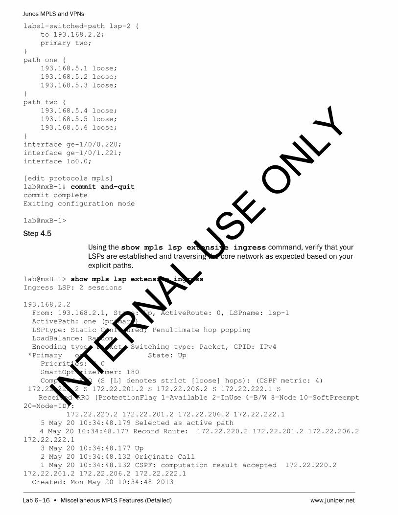
Junos MPLS and VPNs
Lab 6–16 • Miscellaneous MPLS Features (Detailed) www.juniper.net
label-switched-path lsp-2 { to 193.168.2.2; primary two;}path one { 193.168.5.1 loose; 193.168.5.2 loose; 193.168.5.3 loose;}path two { 193.168.5.4 loose; 193.168.5.5 loose; 193.168.5.6 loose;}interface ge-1/0/0.220;interface ge-1/0/1.221;interface lo0.0;
[edit protocols mpls]lab@mxB-1# commit and-quit commit completeExiting configuration mode
lab@mxB-1>
Step 4.5
Using the show mpls lsp extensive ingress command, verify that your LSPs are established and traversing the core network as expected based on your explicit paths.
lab@mxB-1> show mpls lsp extensive ingress Ingress LSP: 2 sessions
193.168.2.2 From: 193.168.2.1, State: Up, ActiveRoute: 0, LSPname: lsp-1 ActivePath: one (primary) LSPtype: Static Configured, Penultimate hop popping LoadBalance: Random Encoding type: Packet, Switching type: Packet, GPID: IPv4 *Primary one State: Up Priorities: 7 0 SmartOptimizeTimer: 180 Computed ERO (S [L] denotes strict [loose] hops): (CSPF metric: 4) 172.22.220.2 S 172.22.201.2 S 172.22.206.2 S 172.22.222.1 S Received RRO (ProtectionFlag 1=Available 2=InUse 4=B/W 8=Node 10=SoftPreempt 20=Node-ID): 172.22.220.2 172.22.201.2 172.22.206.2 172.22.222.1 5 May 20 10:34:48.179 Selected as active path 4 May 20 10:34:48.177 Record Route: 172.22.220.2 172.22.201.2 172.22.206.2 172.22.222.1 3 May 20 10:34:48.177 Up 2 May 20 10:34:48.132 Originate Call 1 May 20 10:34:48.132 CSPF: computation result accepted 172.22.220.2 172.22.201.2 172.22.206.2 172.22.222.1 Created: Mon May 20 10:34:48 2013
INTERNAL U
SE ONLY

Junos MPLS and VPNs
www.juniper.net Miscellaneous MPLS Features (Detailed) • Lab 6–17
193.168.2.2 From: 193.168.2.1, State: Up, ActiveRoute: 0, LSPname: lsp-2 ActivePath: two (primary) LSPtype: Static Configured, Penultimate hop popping LoadBalance: Random Encoding type: Packet, Switching type: Packet, GPID: IPv4 *Primary two State: Up Priorities: 7 0 SmartOptimizeTimer: 180 Computed ERO (S [L] denotes strict [loose] hops): (CSPF metric: 4) 172.22.221.2 S 172.22.203.2 S 172.22.204.2 S 172.22.223.1 S Received RRO (ProtectionFlag 1=Available 2=InUse 4=B/W 8=Node 10=SoftPreempt 20=Node-ID): 172.22.221.2 172.22.203.2 172.22.204.2 172.22.223.1 5 May 20 10:34:48.285 Selected as active path 4 May 20 10:34:48.284 Record Route: 172.22.221.2 172.22.203.2 172.22.204.2 172.22.223.1 3 May 20 10:34:48.284 Up 2 May 20 10:34:48.134 Originate Call 1 May 20 10:34:48.134 CSPF: computation result accepted 172.22.221.2 172.22.203.2 172.22.204.2 172.22.223.1 Created: Mon May 20 10:34:48 2013Total 2 displayed, Up 2, Down 0
Question: Are your LSPs in an Up state?
Answer: Yes, your LSPs should be up and functional at this point. If they are not up, review your configuration. If you need assistance, please contact your instructor.
Question: Do your LSPs traverse the core network as expected?
Answer: Yes, your LSPs should follow the path you defined. If they do not follow the expected path, review your configuration. If you need additional assistance, contact your instructor.
Step 4.6
Enter into configuration mode, navigate to the [edit routing-options] hierarchy, and define the static routes outlined on the network diagram for the device you are configuring.
lab@mxB-1> configure Entering configuration mode
INTERNAL U
SE ONLY

Junos MPLS and VPNs
Lab 6–18 • Miscellaneous MPLS Features (Detailed) www.juniper.net
[edit]lab@mxB-1# edit routing-options
[edit routing-options]lab@mxB-1# set static route route/24 receive
[edit routing-options]lab@mxB-1# set static route route/24 receive
[edit routing-options]lab@mxB-1#
Step 4.7
Navigate to the [edit policy-options policy-statement export-static] hierarchy. Create a policy named export-static that will export these routes to your internal BGP (IBGP) peer.
[edit routing-options]lab@mxB-1# top edit policy-options policy-statement export-static
[edit policy-options policy-statement export-static]lab@mxB-1# set from protocol static
[edit policy-options policy-statement export-static]lab@mxB-1# set then accept
[edit policy-options policy-statement export-static]lab@mxB-1# show from protocol static;then accept;
[edit policy-options policy-statement export-static]lab@mxB-1#
Step 4.8
Apply the new policy as an export policy to your IBGP group. Commit your configuration changes and exit to operational mode.
[edit policy-options policy-statement export-static]lab@mxB-1# top edit protocols bgp group my-int-group
[edit protocols bgp group my-int-group]lab@mxB-1# set export export-static
[edit protocols bgp group my-int-group]lab@mxB-1# commit and-quit commit completeExiting configuration mode
lab@mxB-1>
Step 4.9
Verify that your router is now sending these routes to your neighbor and that you are receiving the remote static prefixes from the remote peer.
INTERNAL U
SE ONLY
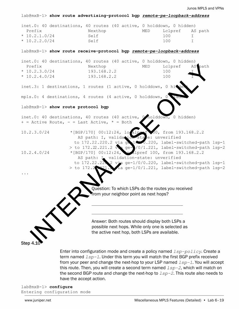
Junos MPLS and VPNs
www.juniper.net Miscellaneous MPLS Features (Detailed) • Lab 6–19
lab@mxB-1> show route advertising-protocol bgp remote-pe-loopback-address
inet.0: 40 destinations, 40 routes (40 active, 0 holddown, 0 hidden) Prefix Nexthop MED Lclpref AS path* 10.2.1.0/24 Self 100 I* 10.2.2.0/24 Self 100 I
lab@mxB-1> show route receive-protocol bgp remote-pe-loopback-address
inet.0: 40 destinations, 40 routes (40 active, 0 holddown, 0 hidden) Prefix Nexthop MED Lclpref AS path* 10.2.3.0/24 193.168.2.2 100 I* 10.2.4.0/24 193.168.2.2 100 I
inet.3: 1 destinations, 1 routes (1 active, 0 holddown, 0 hidden)
mpls.0: 4 destinations, 4 routes (4 active, 0 holddown, 0 hidden)
lab@mxB-1> show route protocol bgp
inet.0: 40 destinations, 40 routes (40 active, 0 holddown, 0 hidden)+ = Active Route, - = Last Active, * = Both
10.2.3.0/24 *[BGP/170] 00:12:24, localpref 100, from 193.168.2.2 AS path: I, validation-state: unverified to 172.22.220.2 via ge-1/0/0.220, label-switched-path lsp-1 > to 172.22.221.2 via ge-1/0/1.221, label-switched-path lsp-210.2.4.0/24 *[BGP/170] 00:12:24, localpref 100, from 193.168.2.2 AS path: I, validation-state: unverified to 172.22.220.2 via ge-1/0/0.220, label-switched-path lsp-1 > to 172.22.221.2 via ge-1/0/1.221, label-switched-path lsp-2...
Question: To which LSPs do the routes you received from your neighbor point as next hops?
Answer: Both routes should display both LSPs a possible next hops. While only one is selected as the active next hop, both LSPs are available.
Step 4.10
Enter into configuration mode and create a policy named lsp-policy. Create a term named lsp-1. Under this term you will match the first BGP prefix received from your peer and change the next-hop to your LSP named lsp-1. You will accept this route. Then, you will create a second term named lsp-2, which will match on the second BGP route and change the next-hop to lsp-2. This route also needs to have the accept action.
lab@mxB-1> configure Entering configuration mode
INTERNAL U
SE ONLY

Junos MPLS and VPNs
Lab 6–20 • Miscellaneous MPLS Features (Detailed) www.juniper.net
[edit]lab@mxB-1# edit policy-options policy-statement lsp-policy
[edit policy-options policy-statement lsp-policy]lab@mxB-1# set term lsp-1 from protocol bgp
[edit policy-options policy-statement lsp-policy]lab@mxB-1# set term lsp-1 from route-filter first-received-route/24 exact
[edit policy-options policy-statement lsp-policy]lab@mxB-1# set term lsp-1 then install-nexthop lsp lsp-1
[edit policy-options policy-statement lsp-policy]lab@mxB-1# set term lsp-1 then accept
[edit policy-options policy-statement lsp-policy]lab@mxB-1# set term lsp-2 from protocol bgp
[edit policy-options policy-statement lsp-policy]lab@mxB-1# set term lsp-2 from route-filter second-received-route/24 exact
[edit policy-options policy-statement lsp-policy]lab@mxB-1# set term lsp-2 then install-nexthop lsp lsp-2
[edit policy-options policy-statement lsp-policy]lab@mxB-1# set term lsp-2 then accept
[edit policy-options policy-statement lsp-policy]lab@mxB-1# show term lsp-1 { from { protocol bgp; route-filter 10.2.3.0/24 exact; } then { install-nexthop lsp lsp-1; accept; }}term lsp-2 { from { protocol bgp; route-filter 10.2.4.0/24 exact; } then { install-nexthop lsp lsp-2; accept; }}
Step 4.11
Navigate to the [edit routing-options] hierarchy and apply the policy lsp-policy as an export policy to the forwarding table. After applying the policy, commit your changes and exit to operational mode.
INTERNAL U
SE ONLY

Junos MPLS and VPNs
www.juniper.net Miscellaneous MPLS Features (Detailed) • Lab 6–21
[edit policy-options policy-statement lsp-policy]lab@mxB-1# top edit routing-options
[edit routing-options]lab@mxB-1# set forwarding-table export lsp-policy
[edit routing-options]lab@mxB-1# commit and-quit commit completeExiting configuration mode
lab@mxB-1>
Step 4.12
Verify that the next hop for each of the remote BGP routes point to the correct LSP as defined in your policy.
lab@mxB-1> show route protocol bgp
inet.0: 40 destinations, 40 routes (40 active, 0 holddown, 0 hidden)+ = Active Route, - = Last Active, * = Both
10.2.3.0/24 *[BGP/170] 00:19:42, localpref 100, from 193.168.2.2 AS path: I, validation-state: unverified to 172.22.220.2 via ge-1/0/0.220, label-switched-path lsp-110.2.4.0/24 *[BGP/170] 00:19:42, localpref 100, from 193.168.2.2 AS path: I, validation-state: unverified to 172.22.221.2 via ge-1/0/1.221, label-switched-path lsp-2...
Question: Do you see the correct LSP selected as the next hop for each of your BGP routes?
Answer: Yes, you should see that the first route displayed has a next-hop of lsp-1 and the second route has a next-hop of lsp-2. If you do not see this, review your configuration and request assistance from your instructor as needed.
STOP Do not proceed until the remote team finishes Part 4.IN
TERNAL USE O
NLY

Junos MPLS and VPNs
Lab 6–22 • Miscellaneous MPLS Features (Detailed) www.juniper.net
Part 5: Using LSP Metric to Control LSP Selection
In this lab part, you will configure the router to use metrics to control LSP selection. You will begin by removing the policy you created in the Part 4. You must also remove the export policy applied to the forwarding table. You will look at the current state of the BGP routes and determined the metric value calculated from the IGP for each of the RSVP routes. You will then manually set the metric on one of the LSPs to be higher than the IGP calculated value. You will then verify the changes and review the changes to the routing table.
Step 5.1
Enter into configuration mode and remove the policy you created in Part 4. You must also remove the export policy applied to the forwarding table because it is no longer defined. Commit your changes when you are ready to proceed.
lab@mxB-1> configure Entering configuration mode
[edit]lab@mxB-1# delete policy-options policy-statement lsp-policy
[edit]lab@mxB-1# delete routing-options forwarding-table export
[edit]lab@mxB-1# commit commit complete
[edit]lab@mxB-1
Step 5.2
Use the show route protocol bgp command to review the current status of your BGP routes received from your peer.
[edit]lab@mxB-1# run show route protocol bgp
inet.0: 40 destinations, 40 routes (40 active, 0 holddown, 0 hidden)+ = Active Route, - = Last Active, * = Both
10.2.3.0/24 *[BGP/170] 00:27:37, localpref 100, from 193.168.2.2 AS path: I, validation-state: unverified to 172.22.220.2 via ge-1/0/0.220, label-switched-path lsp-1 > to 172.22.221.2 via ge-1/0/1.221, label-switched-path lsp-210.2.4.0/24 *[BGP/170] 00:27:37, localpref 100, from 193.168.2.2 AS path: I, validation-state: unverified to 172.22.220.2 via ge-1/0/0.220, label-switched-path lsp-1 > to 172.22.221.2 via ge-1/0/1.221, label-switched-path lsp-2...
INTERNAL U
SE ONLY

Junos MPLS and VPNs
www.juniper.net Miscellaneous MPLS Features (Detailed) • Lab 6–23
Question: How many next hops are associated with each of the BGP routes? Why?
Answer: Both BGP routes are associated with two next hops. This usually means that there are two equal cost paths to the advertised BGP next hop.
Step 5.3
Review the RSVP routes in inet.3 to determine what metric is being calculated by the IGP. This status review provides the current values so that when you manually assign a metric, you can verify that the changes have been applied correctly
[edit]lab@mxB-1# run show route table inet.3
inet.3: 1 destinations, 1 routes (1 active, 0 holddown, 0 hidden)+ = Active Route, - = Last Active, * = Both
193.168.2.2/32 *[RSVP/7/1] 00:25:47, metric 4 to 172.22.220.2 via ge-1/0/0.220, label-switched-path lsp-1 > to 172.22.221.2 via ge-1/0/1.221, label-switched-path lsp-2
Question: Why do you see both LSPs as available next hops?
Answer: You see both LSP as next hops because they have been calculated as equal cost paths. They both have a metric of 4.
Question: What is the metric of both RSVP LSPs that was calculated from the IGP?
Answer: The metric for both RSVP LSPs should be 4.
Step 5.4
Navigate to the [edit protocols mpls] hierarchy and set the metric to 8 for lsp-2. After changing the metric, commit your configuration and exit to operational mode.
[edit]lab@mxB-1# edit protocols mpls
INTERNAL U
SE ONLY

Junos MPLS and VPNs
Lab 6–24 • Miscellaneous MPLS Features (Detailed) www.juniper.net
[edit protocols mpls]lab@mxB-1# set label-switched-path lsp-2 metric 8
[edit protocols mpls]lab@mxB-1# commit and-quit commit completeExiting configuration mode
lab@mxB-1>
Step 5.5
Use the show route protocol bgp command to review the BGP routes for changes.
lab@mxB-1> show route protocol bgp
inet.0: 40 destinations, 40 routes (40 active, 0 holddown, 0 hidden)+ = Active Route, - = Last Active, * = Both
10.2.3.0/24 *[BGP/170] 00:30:10, localpref 100, from 193.168.2.2 AS path: I, validation-state: unverified > to 172.22.220.2 via ge-1/0/0.220, label-switched-path lsp-110.2.4.0/24 *[BGP/170] 00:30:10, localpref 100, from 193.168.2.2 AS path: I, validation-state: unverified > to 172.22.220.2 via ge-1/0/0.220, label-switched-path lsp-1...
Question: What changes do you see in the routing table?
Answer: The two next hops for the BGP routes are no longer available because they are no longer equal cost paths.
Step 5.6
View the inet.3 table to verify the metric change is reflected by the RSVP routes.
lab@mxB-1> show route table inet.3
193.168.3.2/32 *[RSVP/7/1] 04:00:56, metric 4 > to 172.22.230.2 via ge-1/0/0.230, label-switched-path lsp-1 [RSVP/7/1] 00:00:26, metric 8 > to 172.22.231.2 via ge-1/0/1.231, label-switched-path lsp-2
INTERNAL U
SE ONLY

Junos MPLS and VPNs
www.juniper.net Miscellaneous MPLS Features (Detailed) • Lab 6–25
Question: What is the metric of both RSVP LSP routes after the change?
Answer: The metric for RSVP lsp-1 should be 4 and the metric for RSVP lsp-2 should be 8.
Part 6: Configuring Your Router to Not Decrement the TTL
In this lab part, you will configure the router to not decrement the TTL. First, you will look at the default TTL handling behavior. You will configure the router so that the TTL is not decremented as packets traverse the MPLS network.
Step 6.1
Enter into configuration mode and navigate to the [edit protocols mpls] hierarchy. Enable traffic-engineering bgp-igp. This will allow you to traceroute over the MPLS LSPs to the remote teams loopback address. We will be using traceroute to demonstrate the behavior with TTL handling. Commit the change and exit to operational mode before proceeding. By using traffic engineering, it allows internal traffic to use the RSVP routes to get to the remote team’s loopback address.
lab@mxB-1> configure Entering configuration mode
[edit]lab@mxB-1# edit protocols mpls
[edit protocols mpls]lab@mxB-1# set traffic-engineering bgp-igp
[edit protocols mpls]lab@mxB-1# commit and quitcommit completeExiting configuration mode
lab@mxB-1>
Step 6.2
Verify the default behavior by using the traceroute utility. You can now traceroute to the remote team’s loopback address.
lab@mxB-1> traceroute remote-pe-loopback-address traceroute to 193.168.2.2 (193.168.2.2), 30 hops max, 40 byte packets 1 172.22.220.2 (172.22.220.2) 0.766 ms 0.624 ms 0.541 ms MPLS Label=299904 CoS=0 TTL=1 S=1 2 172.22.201.2 (172.22.201.2) 0.574 ms 0.569 ms 0.558 ms MPLS Label=299904 CoS=0 TTL=1 S=1 3 172.22.206.2 (172.22.206.2) 0.598 ms 0.642 ms 0.583 ms MPLS Label=299904 CoS=0 TTL=1 S=1 4 193.168.2.2 (193.168.2.2) 0.680 ms 0.540 ms 0.545 ms
INTERNAL U
SE ONLY

Junos MPLS and VPNs
Lab 6–26 • Miscellaneous MPLS Features (Detailed) www.juniper.net
Question: How many devices respond to the traceroute request?
Answer: You should see four responses. One for each device, including the destination PE device.
Step 6.3
Enter into configuration mode and navigate to the [edit protocols mpls] hierarchy. Configure the router so that the TTL is not decremented by using the no-decrement-ttl statement under the MPLS protocol. Commit the configuration and exit to operational mode before proceeding to the next step.
lab@mxB-1> configure Entering configuration mode
[edit]lab@mxB-1# edit protocols mpls
[edit protocols mpls]lab@mxB-1# set no-decrement-ttl
[edit protocols mpls]lab@mxB-1# commit and-quitcommit completeExiting configuration mode
lab@mxB-1>
Step 6.4
Use the traceroute utility again to view the change in behavior.
lab@mxB-1> traceroute remote-pe-loopback-address traceroute to 193.168.2.2 (193.168.2.2), 30 hops max, 40 byte packets 1 193.168.2.2 (193.168.2.2) 0.866 ms 0.573 ms 0.542 ms
Question: How many responses do you see now?
Answer: You should only see one response. This is the response from the egress device. This makes the MPLS network transparent.
INTERNAL U
SE ONLY

Junos MPLS and VPNs
www.juniper.net Miscellaneous MPLS Features (Detailed) • Lab 6–27
Part 7: Configuring Your Router to Signal Explicit Null
In this lab part, you will configure your router to signal explicit null. Using explicit null notifies the penultimate label-switching router (LSR) that the egress router will remove the MPLS label. You will compare the Labelin value before and after configuring the router to signal explicit null.
Step 7.1
Use the show mpls lsp egress command to view the Labelin value before you configure the router to signal explicit null. You should expect to see a value of 3 for both LSPs.
lab@mxB-1> show mpls lsp egress Egress LSP: 2 sessionsTo From State Rt Style Labelin Labelout LSPname 193.168.2.1 193.168.2.2 Up 0 1 FF 3 - lsp-1193.168.2.1 193.168.2.2 Up 0 1 FF 3 - lsp-2Total 2 displayed, Up 2, Down 0
Step 7.2
Enter into configuration mode and navigate to the [edit protocols mpls] hierarchy. Configure your router to signal explicit null by using the explicit-null command. This command tells the router to signal the upstream LSR (penultimate router) that it expects to receive an MPLS label. In operation, instead of signaling a value of 3 upstream (default behavior), the egress router will signal a value of 0 upstream. Commit the changes and exit to operational mode before proceeding to the next step.
lab@mxB-1> configure Entering configuration mode
[edit]lab@mxB-1# edit protocols mpls
[edit protocols mpls]lab@mxB-1# set explicit-null
[edit protocols mpls]lab@mxB-1# commit and-quitcommit completeExiting configuration mode
lab@mxB-1>
Step 7.3
Use the show mpls lsp egress command to view the Labelin value now that you have configured the router to signal explicit null. You should expect to see a value of 0 for both LSPs.
lab@mxB-1> show mpls lsp egress Egress LSP: 2 sessionsTo From State Rt Style Labelin Labelout LSPname 193.168.2.1 193.168.2.2 Up 0 1 FF 0 - lsp-1193.168.2.1 193.168.2.2 Up 0 1 FF 0 - lsp-2
INTERNAL U
SE ONLY

Junos MPLS and VPNs
Lab 6–28 • Miscellaneous MPLS Features (Detailed) www.juniper.net
Question: Is the value of the Labelin field what you expect to see?
Answer: Yes, the Labelin value should be 0. If it is not please review your configuration and request assistance from your instructor as needed.
Part 8: Configuring Your Router to Automatically Adjust the RSVP Reservation Based on Observed Bandwidth
In this lab part, you will configure your router to monitor and automatically adjust the RSVP reservation based on the observed bandwidth. The first step to setting up automatic bandwidth provisioning is to enable statistics monitoring for the MPLS protocol. This allows MPLS to track and monitor bandwidth utilization over a specified time period (default 24 hours). Next, you will enable the automatic bandwidth provisioning on one of your established LSPs.
Step 8.1
Enter into configuration mode and navigate to the [edit protocols mpls statistics] hierarchy. Enable MPLS statistics monitoring by creating a file named auto-stats and configuring the auto-bandwidth statement.
lab@mxB-1> configure Entering configuration mode
[edit]lab@mxB-1# edit protocols mpls statistics
[edit protocols mpls statistics]lab@mxB-1# set file auto-stats
[edit protocols mpls statistics]lab@mxB-1# set auto-bandwidth
[edit protocols mpls statistics]lab@mxB-1#
Step 8.2
Navigate to the [edit protocols mpls] and enable auto-bandwidth under the existing LSP lsp-1. Commit your changes and exit to operational mode before proceeding to the next step.
[edit protocols mpls statistics]lab@mxB-1# up
[edit protocols mpls]lab@mxB-1# set label-switched-path lsp-1 auto-bandwidth
INTERNAL U
SE ONLY

Junos MPLS and VPNs
www.juniper.net Miscellaneous MPLS Features (Detailed) • Lab 6–29
[edit protocols mpls]lab@mxB-1# commit and-quit commit completeExiting configuration mode
lab@mxB-1>
Step 8.3
Verify that your configuration changes have taken affect on the LSP by executing the show mpls lsp ingress name lsp-1 extensive command.
lab@mxB-1> show mpls lsp ingress name lsp-1 extensive Ingress LSP: 2 sessions
193.168.2.2 From: 193.168.2.1, State: Up, ActiveRoute: 0, LSPname: lsp-1 ActivePath: one (primary) LSPtype: Static Configured, Penultimate hop popping LoadBalance: Random Autobandwidth AdjustTimer: 86400 secs Max AvgBW util: 0bps, Bandwidth Adjustment in 86382 second(s). Overflow limit: 0, Overflow sample count: 0 Underflow limit: 0, Underflow sample count: 0, Underflow Max AvgBW: 0bps Encoding type: Packet, Switching type: Packet, GPID: IPv4 *Primary one State: Up, No-decrement-ttl Priorities: 7 0 SmartOptimizeTimer: 180 Computed ERO (S [L] denotes strict [loose] hops): (CSPF metric: 4) 172.22.220.2 S 172.22.201.2 S 172.22.206.2 S 172.22.222.1 S Received RRO (ProtectionFlag 1=Available 2=InUse 4=B/W 8=Node 10=SoftPreempt 20=Node-ID): 172.22.220.2 172.22.201.2 172.22.206.2 172.22.222.1 5 May 20 11:15:03.200 Selected as active path 4 May 20 11:15:03.199 Record Route: 172.22.220.2 172.22.201.2 172.22.206.2 172.22.222.1 3 May 20 11:15:03.198 Up 2 May 20 11:15:03.155 Originate Call 1 May 20 11:15:03.155 CSPF: computation result accepted 172.22.220.2 172.22.201.2 172.22.206.2 172.22.222.1 Created: Mon May 20 11:15:02 2013Total 1 displayed, Up 1, Down 0
Question: When will the next LSP adjustment happen?
Answer: Answers will vary depending on the duration between enabling the auto-bandwidth feature and executing the show command. In our example above the next adjustment will happen in 86382 seconds.
INTERNAL U
SE ONLY

Junos MPLS and VPNs
Lab 6–30 • Miscellaneous MPLS Features (Detailed) www.juniper.net
Part 9: Using MPLS Ping to Verify LSP Connectivity
In this lab part, you will use MPLS Pings to verify LSP connectivity to the egress node.
Step 9.1
Verify the connectivity of lsp-1 by executing the command ping mpls rsvp lsp-1.
lab@mxB-1> ping mpls rsvp lsp-1 !!!!!--- lsping statistics ---5 packets transmitted, 5 packets received, 0% packet loss
Question: Do the pings complete?
Answer: Yes, your pings should complete at this point. If they do not check with the remote team and ensure they have the 127.0.0.1/32 address assigned to their loopback. If you need assistance, consult with your instructor.
Step 9.2
Log out of your assigned device using the exit command.
lab@mxB-1> exit
mxB-1 (ttyu0)
login:
STOP Tell your instructor that you have completed this lab.
INTERNAL U
SE ONLY
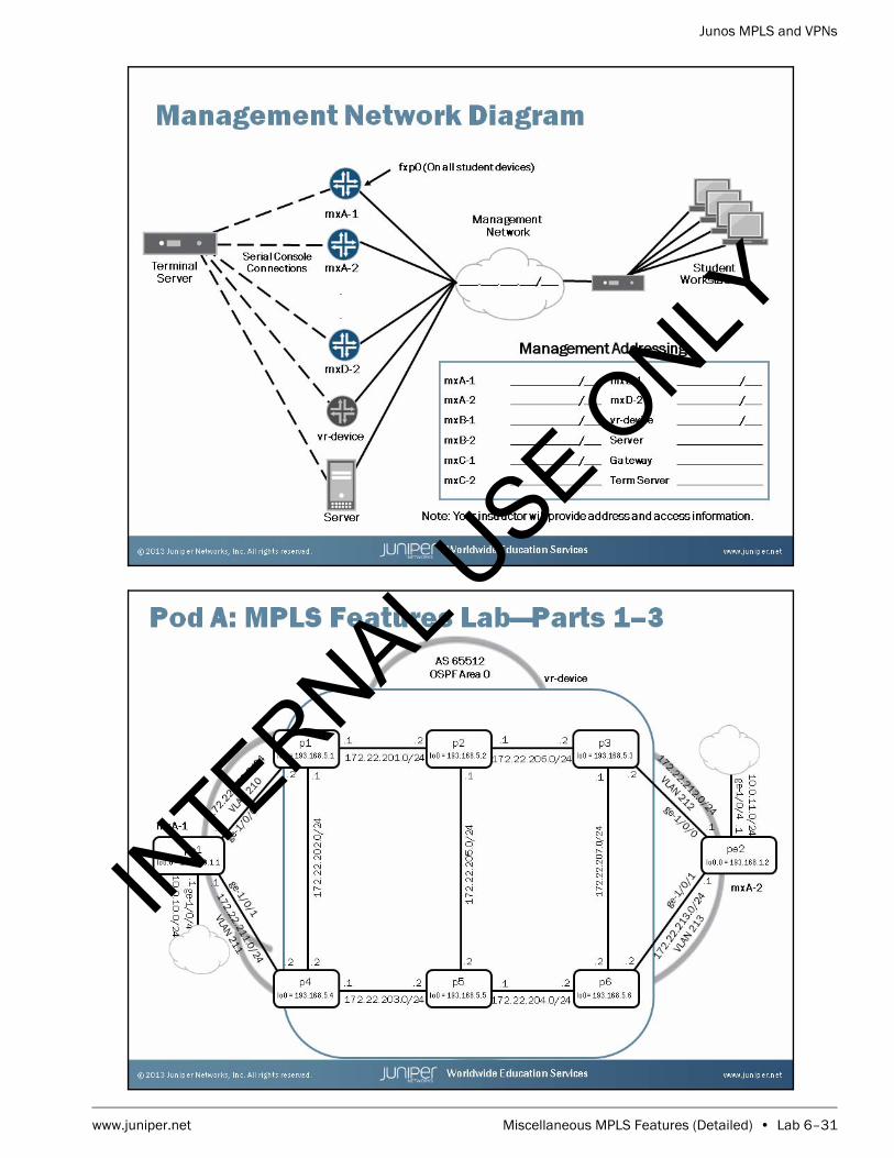
Junos MPLS and VPNs
www.juniper.net Miscellaneous MPLS Features (Detailed) • Lab 6–31
INTERNAL U
SE ONLY

Junos MPLS and VPNs
Lab 6–32 • Miscellaneous MPLS Features (Detailed) www.juniper.net
INTERNAL U
SE ONLY

Junos MPLS and VPNs
www.juniper.net Miscellaneous MPLS Features (Detailed) • Lab 6–33
INTERNAL U
SE ONLY

Junos MPLS and VPNs
Lab 6–34 • Miscellaneous MPLS Features (Detailed) www.juniper.net
INTERNAL U
SE ONLY

Junos MPLS and VPNs
www.juniper.net Miscellaneous MPLS Features (Detailed) • Lab 6–35
INTERNAL U
SE ONLY

Junos MPLS and VPNs
Lab 6–36 • Miscellaneous MPLS Features (Detailed) www.juniper.net
INTERNAL U
SE ONLY

www.juniper.net L3VPN Static and BGP Routing (Detailed) • Lab 7–1
LabL3VPN Static and BGP Routing (Detailed)
Overview
In this lab, you will establish a point-to-point Layer 3 VPN using RSVP signaling between provider edge (PE) routers. You will also configure both static and BGP routing between your PE and customer edge (CE) routers. You will share your routes with the remote PE router through the Layer 3 VPN using Multiprotocol Border Gateway Protocol (MP-BGP).
The lab is available in two formats: a high-level format that is designed to make you think through each step and a detailed format that offers step-by-step instructions complete with sample output from most commands.
By completing this lab, you will perform the following tasks:
• Load the a baseline configuration for your router. This configuration includes your baseline core configuration including OSPF and BGP. The baseline also contains a logical router configuration that will act as your CE router for this lab.
• Configure an RSVP-signaled label-switched path (LSP) to the remote PE router.
• Create and establish a Layer 3 VPN over the core network.
• Configure static routing between your PE and CE router and share your static PE routes through the Layer 3 VPN using MP-BGP.
• Configure BGP routing between your PE and CE routers and share CE routes through the Layer 3 VPN using MP-BGP.
• Verify connectivity and behavior using command-line interface (CLI) operational mode commands including ping and commands used to examine routing tables and PE-PE BGP announcements.
INTERNAL U
SE ONLY

Junos MPLS and VPNs
Lab 7–2 • L3VPN Static and BGP Routing (Detailed) www.juniper.net
Part 1: Creating the Baseline SP Network and Enabling PE for Layer 3 VPN Signaling
In this lab part, you will configure the baseline network for the lab. You will load a baseline configuration and then enable Resource Reservation Protocol (RSVP) and multiprotocol label switching (MPLS) on the core-facing interfaces, configure MP-BGP, and configure a route-distinguisher ID.
Step 1.1
Ensure that you know to which device you are assigned. Check with your instructor if necessary.
Step 1.2
Consult the management network diagram, provided by your instructor, to determine your device’s management address.
Question: What is the management address assigned to your station?
Answer: The answer varies. The sample hostname and IP address used in the output examples in this lab are for mxB-1, which uses 10.210.15.3 as its management IP address. The actual management subnet varies between delivery environments.
Note
The instructor will tell you the nature of your access and will provide you with the necessary details to access your assigned device.
INTERNAL U
SE ONLY
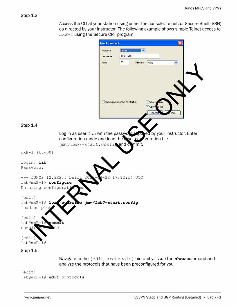
Junos MPLS and VPNs
www.juniper.net L3VPN Static and BGP Routing (Detailed) • Lab 7–3
Step 1.3
Access the CLI at your station using either the console, Telnet, or Secure Shell (SSH) as directed by your instructor. The following example shows simple Telnet access to mxB-1 using the Secure CRT program.
Step 1.4
Log in as user lab with the password supplied by your instructor. Enter configuration mode and load the reset configuration file jmv/lab7-start.config and commit.
mxB-1 (ttyp0)
login: labPassword:
--- JUNOS 12.3R2.5 built 2013-03-22 17:12:14 UTClab@mxB-1> configure Entering configuration mode
[edit]lab@mxB-1# load override jmv/lab7-start.config load complete
[edit]lab@mxB-1# commit commit complete
[edit]lab@mxB-1#
Step 1.5
Navigate to the [edit protocols] hierarchy. Issue the show command and analyze the protocols that have been preconfigured for you.
[edit]lab@mxB-1# edit protocols
INTERNAL U
SE ONLY

Junos MPLS and VPNs
Lab 7–4 • L3VPN Static and BGP Routing (Detailed) www.juniper.net
[edit protocols]lab@mxB-1# show bgp { group my-int-group { type internal; local-address 193.168.2.1; neighbor 193.168.2.2; }}ospf { area 0.0.0.0 { interface ge-1/0/0.220; interface ge-1/0/1.221; interface lo0.0; }}
[edit protocols]lab@mxB-1#
Question: Which protocols have been preconfigured for you?
Answer: OSPF and BGP have been preconfigured.
Question: In its current state, will your router be able to build a traffic engineering database (TED)?
Answer: Your router will not be able to build a TED because traffic-engineering has not been enabled for OSPF.
Question: What is the name of the preconfigured BGP peer group? Which router in the network is configured as a member of the group?
Answer: The configured peer group is called my-int-group. The group is configured to establish an IBGP session with the remote PE.
Step 1.6
Exit to operational mode and verify your Open Shortest Path First (OSPF) neighbor relationships are up and operational.
INTERNAL U
SE ONLY

Junos MPLS and VPNs
www.juniper.net L3VPN Static and BGP Routing (Detailed) • Lab 7–5
[edit protocols]lab@mxB-1# exit configuration-mode Exiting configuration mode
lab@mxB-1> show ospf neighbor Address Interface State ID Pri Dead172.22.220.2 ge-1/0/0.220 Full 193.168.5.1 128 34172.22.221.2 ge-1/0/1.221 Full 193.168.5.4 128 39
Question: What is the state of your PE router’s OSPF neighbors?
Answer: After a short time, the OSPF neighbors should attain the Full state.
Step 1.7
Verify that your PE router has established an IBGP neighbor relationship with the remote PE router.
lab@mxB-1> show bgp neighborPeer: 193.168.2.2+179 AS 65512 Local: 193.168.2.1+58282 AS 65512 Type: Internal State: Established Flags: <Sync> Last State: OpenConfirm Last Event: RecvKeepAlive Last Error: None Options: <Preference LocalAddress Refresh> Local Address: 193.168.2.1 Holdtime: 90 Preference: 170 Number of flaps: 0 Peer ID: 193.168.2.2 Local ID: 193.168.2.1 Active Holdtime: 90 Keepalive Interval: 30 Group index: 0 Peer index: 0 BFD: disabled, down NLRI for restart configured on peer: inet-unicast NLRI advertised by peer: inet-unicast NLRI for this session: inet-unicast Peer supports Refresh capability (2) Stale routes from peer are kept for: 300 Peer does not support Restarter functionality NLRI that restart is negotiated for: inet-unicast NLRI of received end-of-rib markers: inet-unicast NLRI of all end-of-rib markers sent: inet-unicast Peer supports 4 byte AS extension (peer-as 65512) Peer does not support Addpath Table inet.0 Bit: 10001 RIB State: BGP restart is complete Send state: in sync Active prefixes: 0 Received prefixes: 0 Accepted prefixes: 0 Suppressed due to damping: 0 Advertised prefixes: 0 Last traffic (seconds): Received 19 Sent 8 Checked 31 Input messages: Total 9219 Updates 4 Refreshes 0 Octets 175246
INTERNAL U
SE ONLY

Junos MPLS and VPNs
Lab 7–6 • L3VPN Static and BGP Routing (Detailed) www.juniper.net
Output messages: Total 9218 Updates 2 Refreshes 0 Octets 175250 Output Queue[0]: 0
Question: Is the neighbor relationship in the established state with the remote PE router?
Answer: The remote PE router should be in an established state with your PE router. If it is not, double check the interface and BGP settings. If you need further assistance, consult with your instructor.
Question: What address family has been negotiated for the BGP session? What type of routes can be advertised between the two PE routers?
Answer: The PE routers have negotiated the advertisement of inet-unicast routes. That means that only IPv4 unicast routes can be advertised between the two neighbors.
Step 1.8
For an interface to support the forwarding of MPLS packets, you must enable the MPLS family on each interface. Enter configuration mode and navigate to the [edit interfaces] hierarchy and enable family mpls on both of the core-facing interfaces.
lab@mxB-1> configure Entering configuration mode
[edit]lab@mxB-1# edit interfaces
[edit interfaces]lab@mxB-1# set ge-1/0/0 unit unit family mpls
[edit interfaces]lab@mxB-1# set ge-1/0/1 unit unit family mpls
[edit interfaces]lab@mxB-1#
Step 1.9
Navigate to the [edit protocols] hierarchy and configure the MPLS protocol on the core-facing interfaces.
INTERNAL U
SE ONLY
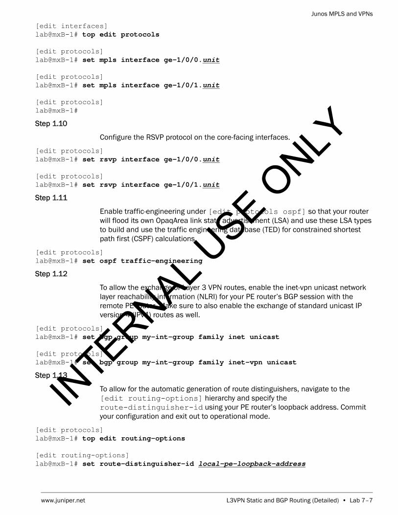
Junos MPLS and VPNs
www.juniper.net L3VPN Static and BGP Routing (Detailed) • Lab 7–7
[edit interfaces]lab@mxB-1# top edit protocols
[edit protocols]lab@mxB-1# set mpls interface ge-1/0/0.unit
[edit protocols]lab@mxB-1# set mpls interface ge-1/0/1.unit
[edit protocols]lab@mxB-1#
Step 1.10
Configure the RSVP protocol on the core-facing interfaces.
[edit protocols]lab@mxB-1# set rsvp interface ge-1/0/0.unit
[edit protocols]lab@mxB-1# set rsvp interface ge-1/0/1.unit
Step 1.11
Enable traffic-engineering under [edit protocols ospf] so that your router will flood its own OpaqArea link state advertisement (LSA) and use these LSA types to build and use the traffic engineering database (TED) for constrained shortest path first (CSPF) calculations.
[edit protocols]lab@mxB-1# set ospf traffic-engineering
Step 1.12
To allow the exchange of Layer 3 VPN routes, enable the inet-vpn unicast network layer reachability information (NLRI) for your PE router’s BGP session with the remote PE router. Make sure to also enable the exchange of standard unicast IP version 4 (IPv4) routes as well.
[edit protocols]lab@mxB-1# set bgp group my-int-group family inet unicast
[edit protocols]lab@mxB-1# set bgp group my-int-group family inet-vpn unicast
Step 1.13
To allow for the automatic generation of route distinguishers, navigate to the [edit routing-options] hierarchy and specify the route-distinguisher-id using your PE router’s loopback address. Commit your configuration and exit out to operational mode.
[edit protocols]lab@mxB-1# top edit routing-options
[edit routing-options]lab@mxB-1# set route-distinguisher-id local-pe-loopback-address
INTERNAL U
SE ONLY

Junos MPLS and VPNs
Lab 7–8 • L3VPN Static and BGP Routing (Detailed) www.juniper.net
[edit routing-options]lab@mxB-1# commit and-quit commit completeExiting configuration mode
lab@mxB-1>
Step 1.14
Using show commands, verify that MPLS and RSVP are configured correctly on the core-facing interfaces.
lab@mxB-1> show mpls interface Interface State Administrative groups (x: extended)ge-1/0/0.220 Up <none>ge-1/0/1.221 Up <none>
lab@mxB-1> show rsvp interface RSVP interface: 2 active Active Subscr- Static Available Reserved HighwaterInterface State resv iption BW BW BW markge-1/0/0.220Up 0 100% 1000Mbps 1000Mbps 0bps 0bps ge-1/0/1.221Up 0 100% 1000Mbps 1000Mbps 0bps 0bps
Question: Can your core-facing interfaces now support the transmission of MPLS packets?
Answer: The outputs of the two commands show that the two interfaces can now support the forwarding of MPLS packets.
Step 1.15
Verify the state of your PE router’s BGP neighbor relationship with the remote PE router.
lab@mxB-1> show bgp neighbor remote-pe-loopback-addressPeer: 193.168.2.2+52281 AS 65512 Local: 193.168.2.1+179 AS 65512 Type: Internal State: Established Flags: <Sync> Last State: OpenConfirm Last Event: RecvKeepAlive Last Error: None Options: <Preference LocalAddress AddressFamily Rib-group Refresh> Address families configured: inet-unicast inet-vpn-unicast Local Address: 193.168.2.1 Holdtime: 90 Preference: 170 Number of flaps: 1 Last flap event: RecvNotify Error: 'Cease' Sent: 0 Recv: 1 Peer ID: 193.168.2.2 Local ID: 193.168.2.1 Active Holdtime: 90 Keepalive Interval: 30 Group index: 0 Peer index: 0 BFD: disabled, down NLRI for restart configured on peer: inet-unicast inet-vpn-unicast NLRI advertised by peer: inet-unicast inet-vpn-unicast NLRI for this session: inet-unicast inet-vpn-unicast
INTERNAL U
SE ONLY

Junos MPLS and VPNs
www.juniper.net L3VPN Static and BGP Routing (Detailed) • Lab 7–9
Peer supports Refresh capability (2) Stale routes from peer are kept for: 300 Peer does not support Restarter functionality NLRI that restart is negotiated for: inet-unicast inet-vpn-unicast NLRI of received end-of-rib markers: inet-unicast inet-vpn-unicast NLRI of all end-of-rib markers sent: inet-unicast inet-vpn-unicast Peer supports 4 byte AS extension (peer-as 65512) Peer does not support Addpath Table inet.0 Bit: 10000 RIB State: BGP restart is complete Send state: in sync Active prefixes: 0 Received prefixes: 0 Accepted prefixes: 0 Suppressed due to damping: 0 Advertised prefixes: 0 Table bgp.l3vpn.0 RIB State: BGP restart is complete RIB State: VPN restart is complete Send state: not advertising Active prefixes: 0 Received prefixes: 0 Accepted prefixes: 0 Suppressed due to damping: 0 Last traffic (seconds): Received 15 Sent 15 Checked 15 Input messages: Total 4 Updates 2 Refreshes 0 Octets 139 Output messages: Total 3 Updates 0 Refreshes 0 Octets 158 Output Queue[0]: 0 Output Queue[1]: 0
Question: Is the neighbor relationship in the established state with the remote PE?
Answer: The remote PE router should be in an established state with your PE router. If it is not, double check the interface and BGP settings. If you need further assistance, consult with your instructor.
Question: What NLRI type has been negotiated between your PE router and the remote PE router?
Answer: Using the show bgp neighbor command, you should see that the NLRI for this session should be inet-unicast and inet-vpn-unicast.
INTERNAL U
SE ONLY

Junos MPLS and VPNs
Lab 7–10 • L3VPN Static and BGP Routing (Detailed) www.juniper.net
Part 2: Establishing an RSVP Signaled LSP Between PE Routers
In this lab part, you will configure an RSVP-signaled LSP between the PE routers. You will verify reachability using the MPLS ping utility.
Step 2.1
Enter configuration mode and navigate to the [edit protocols mpls] hierarchy and configure a label-switched-path called localPE-to-remotePE-pod. For example, if you are assigned router mxB-1, your peer router is mxB-2 and your pod is B. The LSP for mxB-1 should be named pe1-to-pe2-B. Your LSP should egress at your remote peer’s loopback address. Verify the configuration looks correct. Commit and exit to operation mode when you are satisfied with the changes.
lab@mxB-1> configure Entering configuration mode
[edit]lab@mxB-1# edit protocols mpls
[edit protocols mpls]lab@mxB-1# set label-switched-path localPE-to-remotePE-pod to
remote-pe-loopback-address
[edit protocols mpls]lab@mxB-1# show label-switched-path pe1-to-pe2-B { to 193.168.2.2;}interface ge-1/0/0.220;interface ge-1/0/1.221;
[edit protocols mpls]lab@mxB-1# commit and-quit commit completeExiting configuration mode
lab@mxB-1>
Step 2.2
Use the show mpls lsp command to verify that the RSVP LSP you just configured is up and functional. Ensure that you have bidirectional LSPs before proceeding.
lab@mxB-1> show mpls lsp Ingress LSP: 1 sessionsTo From State Rt P ActivePath LSPname193.168.2.2 193.168.2.1 Up 0 * pe1-to-pe2-BTotal 1 displayed, Up 1, Down 0
Egress LSP: 1 sessionsTo From State Rt Style Labelin Labelout LSPname 193.168.2.1 193.168.2.2 Up 0 1 FF 3 - pe2-to-pe1-BTotal 1 displayed, Up 1, Down 0
INTERNAL U
SE ONLY

Junos MPLS and VPNs
www.juniper.net L3VPN Static and BGP Routing (Detailed) • Lab 7–11
Transit LSP: 0 sessionsTotal 0 displayed, Up 0, Down 0
Question: Are bidirectional LSPs established between your PE router and the remote PE router?
Answer: Your PE router should now be the ingress and egress LSR for LSPs established with the remote PE. You may need to wait some time before the remote team has configured it LSP.
Step 2.3
Use the show route table inet.3 command to review the inet.3 routing table and verify that the RSVP route is present and ready to use.
lab@mxB-1> show route table inet.3
inet.3: 1 destinations, 1 routes (1 active, 0 holddown, 0 hidden)+ = Active Route, - = Last Active, * = Both
193.168.2.2/32 *[RSVP/7/1] 00:07:55, metric 4 > to 172.22.221.2 via ge-1/0/1.221, label-switched-path
pe1-to-pe2-B
Question: Is the appropriate RSVP route to the remote PE router present in the inet.3 routing table?
Answer: Yes, you should see a single RSVP route in your inet.3 routing table for the loopback address of the remote team’s PE router.
Step 2.4
Verify MPLS connectivity using the MPLS ping utility.
lab@mxB-1> ping mpls rsvp localPE-to-remotePE-pod !!!!!--- lsping statistics ---5 packets transmitted, 5 packets received, 0% packet loss
Question: Does your MPLS ping complete?
Answer: Yes, your ping should complete. If it does not, please review your configuration and ask your instructor for assistance, if needed.
INTERNAL U
SE ONLY

Junos MPLS and VPNs
Lab 7–12 • L3VPN Static and BGP Routing (Detailed) www.juniper.net
Part 3: Verify CE Router Configuration
In this lab part you will view the configuration for CE router (logical system) that was preconfigured as part of the loaded starting configuration in Part 1 of this lab.
Step 3.1
Use the set cli logical-system command to place the CLI in the context of the CE router logical system.
lab@mxB-1> set cli logical-system local-ce-hostname Logical system: ceB-1
lab@mxB-1:ceB-1>
Step 3.2
Issue the show configuration command to view the configuration of the CE router.
lab@mxB-1:ceB-1> show configuration interfaces { ge-1/1/4 { unit 620 { vlan-id 620; family inet { address 10.0.20.2/24; } } } lo0 { unit 1 { family inet { address 193.168.12.1/32; } } }}policy-options { policy-statement exp-policy { term 10 { from protocol static; then accept; } term 20 { from protocol direct; then accept; } }}
INTERNAL U
SE ONLY

Junos MPLS and VPNs
www.juniper.net L3VPN Static and BGP Routing (Detailed) • Lab 7–13
routing-options { static { route 172.20.0.0/24 reject; route 172.20.1.0/24 reject; route 172.20.2.0/24 reject; route 172.20.3.0/24 reject; } autonomous-system 65201;}
Question: What interfaces have been configured on the CE router? According to the lab diagram, do they have the appropriate IP addressing?
Answer: The CE router should have both the loopback and ge-1/1/4 interface configured with the appropriate addressing according to the lab diagram.
Question: What is configured under the routing-options hierarchy? According to the lab diagram, are these setting appropriate?
Answer: Four static routes (next hop of reject) and the CE router’s autonomous system should be configured under routing-options hierarchy. These settings are appropriate.
Question: What is configured under the policy-options hierarchy? What does this policy do?
Answer: A policy called exp-policy is configured under policy-options hierarchy. If applied as an export policy, this policy will redistribute active direct and static routes into the protocol to which it is applied. It is currently not applied to any protocol in the configuration.
Step 3.3
Use the ping utility to attempt to ping the local PE router’s ge-1/0/4 interface.
INTERNAL U
SE ONLY

Junos MPLS and VPNs
Lab 7–14 • L3VPN Static and BGP Routing (Detailed) www.juniper.net
lab@mxB-1:ceB-1> ping local-pe-address count 1 PING 10.0.20.1 (10.0.20.1): 56 data bytes
--- 10.0.20.1 ping statistics ---1 packets transmitted, 0 packets received, 100% packet loss
Question: Does your ping succeed? Why?
Answer: The pings do not succeed because the PE router’s ge-1/0/4 interface has not been configured at this point in the lab.
STOP Do not proceed until the remote team finishes Part 3.
Part 4: Configuring the PE to CE Interface
In this lab part, you will configure the PE to CE interface. You will verify reachability using the ping utility.
Step 4.1
Issue the clear cli logical-system to return to the CLI context of the default routing instance (your PE router).
lab@mxB-1:ceB-1> clear cli logical-system Cleared default logical system
lab@mxB-1>
Step 4.2
Enter configuration mode and navigate to the [edit interfaces] hierarchy. Configure the appropriate ge-1/0/4 interface properties found on the network diagram. Commit your changes and exit to operational mode to verify reachability to the CE interface.
lab@mxB-1> configure Entering configuration mode
[edit]lab@mxB-1# edit interfaces
[edit interfaces]lab@mxB-1# set ge-1/0/4 vlan-tagging unit unit vlan-id vlan-id family inet
address address/24
INTERNAL U
SE ONLY

Junos MPLS and VPNs
www.juniper.net L3VPN Static and BGP Routing (Detailed) • Lab 7–15
[edit interfaces]lab@mxB-1# commit and-quit commit completeExiting configuration mode
lab@mxB-1>
Step 4.3
Verify connectivity to the CE device using the ping utility with a count value of 3.
lab@mxB-1> ping local-ce-address count 3 PING 10.0.20.2 (10.0.20.2): 56 data bytes64 bytes from 10.0.20.2: icmp_seq=0 ttl=64 time=2.048 ms64 bytes from 10.0.20.2: icmp_seq=1 ttl=64 time=0.595 ms64 bytes from 10.0.20.2: icmp_seq=2 ttl=64 time=0.609 ms
--- 10.0.20.2 ping statistics ---3 packets transmitted, 3 packets received, 0% packet lossround-trip min/avg/max/stddev = 0.595/1.084/2.048/0.682 ms
Question: Does your ping complete?
Answer: Yes, your ping should complete. If it does not, please review your configuration and ask your instructor for assistance, if needed.
Part 5: Configuring a Layer 3 VPN Instance
In this lab part, you will configure a Layer 3 VPN instance. You will assign a unique route distinguisher and a unique route target. You will include your CE facing interface within this instance. In this lab, you will be using the vrf-target option because of its simplicity. Please note that vrf-import and vrf-export policies would work also.
Step 5.1
Enter into configuration mode and navigate to the [edit routing-instances] hierarchy. Create a new VPN routing and forwarding (VRF) instance named vpn-pod.. For example, if you are assigned router mxB-1, your pod is B. The routing instance for mxB-1 should be named vpn-B.
lab@mxB-1> configure Entering configuration mode
[edit]lab@mxB-1# edit routing-instances
[edit routing-instances]lab@mxB-1# set vpn-pod instance-type vrf
INTERNAL U
SE ONLY

Junos MPLS and VPNs
Lab 7–16 • L3VPN Static and BGP Routing (Detailed) www.juniper.net
[edit routing-instances]lab@mxB-1#
Step 5.2
Navigate to the [edit routing-instances vpn-pod] hierarchy. Create a route distinguisher using your local loopback address to uniquely identify routes advertised from this router. The format should look like this: loopback-address:1.
[edit routing-instances]lab@mxB-1# edit vpn-pod
[edit routing-instances vpn-B]lab@mxB-1# set route-distinguisher loopback-address:1
[edit routing-instances vpn-B]lab@mxB-1#
Step 5.3
Configure your route target. As mentioned previously, you will be using the vrf-target option. Your target will contain the local autonomous system (AS) number and will be uniquely identified by using your pod value. Use the following table to determine the format of your vrf-target.
[edit routing-instances vpn-B]lab@mxB-1# set vrf-target target-community
Step 5.4
Include the CE facing interface in your VRF instance.
[edit routing-instances vpn-B]lab@mxB-1# set interface ge-1/0/4.unit
Step 5.5
Review your recent configuration changes. When you are satisfied with these changes, commit your configuration and exit to operational mode.
[edit routing-instances vpn-B]lab@mxB-1# show instance-type vrf;interface ge-1/0/4.620;route-distinguisher 193.168.2.1:1;vrf-target target:65512:2;
Pod Target Community
A target:65512:1
B target:65512:2
C target:65512:3
D target:65512:4
INTERNAL U
SE ONLY

Junos MPLS and VPNs
www.juniper.net L3VPN Static and BGP Routing (Detailed) • Lab 7–17
[edit routing-instances vpn-B]lab@mxB-1# commit and-quit commit completeExiting configuration mode
lab@mxB-1>
Step 5.6
Verify that your VRF routing table has been created and it contains the local and direct routes for your CE facing interface. You can accomplish this by issuing the show route table vpn-pod.inet.0 command.
lab@mxB-1> show route table vpn-pod.inet.0
vpn-B.inet.0: 2 destinations, 2 routes (2 active, 0 holddown, 0 hidden)+ = Active Route, - = Last Active, * = Both
10.0.20.0/24 *[Direct/0] 00:01:07 > via ge-1/0/4.62010.0.20.1/32 *[Local/0] 00:01:07 Local via ge-1/0/4.620
Question: Do you see your local and direct routes?
Answer: You should see a /32 local route for the ge-1/0/4 interface and a /24 direct route for the network attached to that interface. If you do not see these routes, please review your configuration and ask your instructor for assistance, if needed.
STOP Do not proceed until the remote team finishes Part 5.
Part 6: Configuring Static Routing Between the PE and CE Routers
In this lab part, you will configure static routes to pass traffic from your PE router to your CE router. These routes will be passed through the MP-BGP session to the remote PE router so that traffic can be routed from the remote CE site. You will configure a default route on your CE router. You will configure static routes on your PE router, under your VRF instance, for the four static routes already created on the CE device. You will also configure a static route for the loopback address of your CE router. You will verify that these routes are shared with the remote PE device and you must also verify that you are receiving the routes from the remote PE. You will use the ping utility to test the CE to CE connectivity over the Layer 3 VPN.
Step 6.1
Use the set cli logical-system command to place the CLI in the context of the CE router logical system.
INTERNAL U
SE ONLY

Junos MPLS and VPNs
Lab 7–18 • L3VPN Static and BGP Routing (Detailed) www.juniper.net
lab@mxB-1> set cli logical-system local-ce-hostname Logical system: ceB-1
lab@mxB-1:ceB-1>
Step 6.2
Enter configuration mode and navigate to the [edit routing-options] hierarchy. Configure a static default route that points to the PE interface address as the next hop.
lab@mxB-1:ceB-1> configure Entering configuration mode
[edit]lab@mxB-1:ceB-1# edit routing-options
[edit routing-options]lab@mxB-1:ceB-1# set static route 0/0 next-hop local-pe-address
[edit routing-options]lab@mxB-1:ceB-1# commit and-quit commit completeExiting configuration mode
lab@mxB-1:ceB-1>
Step 6.3
Issue the show route command that the default route now exists in the CE router’s routing table.
lab@mxB-1:ceB-1> show route
inet.0: 8 destinations, 8 routes (8 active, 0 holddown, 0 hidden)+ = Active Route, - = Last Active, * = Both
0.0.0.0/0 *[Static/5] 00:02:37 > to 10.0.20.1 via ge-1/1/4.62010.0.20.0/24 *[Direct/0] 03:49:54 > via ge-1/1/4.62010.0.20.2/32 *[Local/0] 03:49:54 Local via ge-1/1/4.620172.20.0.0/24 *[Static/5] 03:49:54 Reject172.20.1.0/24 *[Static/5] 03:49:54 Reject172.20.2.0/24 *[Static/5] 03:49:54 Reject172.20.3.0/24 *[Static/5] 03:49:54 Reject193.168.12.1/32 *[Direct/0] 03:49:54 > via lo0.1
INTERNAL U
SE ONLY

Junos MPLS and VPNs
www.juniper.net L3VPN Static and BGP Routing (Detailed) • Lab 7–19
Question: Is the default route active in the CE router’s routing table?
Answer: The default route should be active in the routing table. If you do not see the route, please review your configuration ensuring that you chose the correct next hop address value. Ask your instructor for assistance, if needed.
Step 6.4
Issue the clear cli logical-system to return to the CLI context of the default routing instance (your PE router).
lab@mxB-1:ceB-1> clear cli logical-system Cleared default logical system
lab@mxB-1>
Step 6.5
Enter configuration mode and navigate to the [edit routing-instances vpn-pod routing-options] hierarchy. Configure the static routes in your PE instance for the static networks that reside on your CE device. You must also configure a static route for the loopback address of your CE device. All static route next hops should point to the CE router’s ge-1/1/4 interface address.
lab@mxB-1> configure Entering configuration mode
[edit]lab@mxB-1# edit routing-instances vpn-pod routing-options
[edit routing-instances vpn-B routing-options]lab@mxB-1# set static route network/24 next-hop ce-address
[edit routing-instances vpn-B routing-options]lab@mxB-1# set static route network/24 next-hop ce-address
[edit routing-instances vpn-B routing-options]lab@mxB-1# set static route network/24 next-hop ce-address
[edit routing-instances vpn-B routing-options]lab@mxB-1# set static route network/24 next-hop ce-address
[edit routing-instances vpn-B routing-options]lab@mxB-1# set static route ce-loopback-address next-hop ce-address
[edit routing-instances vpn-B routing-options]lab@mxB-1# commit and-quit commit completeExiting configuration mode
lab@mxB-1>
INTERNAL U
SE ONLY
Junos MPLS and VPNs
Lab 7–20 • L3VPN Static and BGP Routing (Detailed) www.juniper.net
Step 6.6
Verify that you are advertising your routes to the remote PE router.
lab@mxB-1> show route advertising-protocol bgp remote-pe-loopback-address
vpn-B.inet.0: 13 destinations, 13 routes (13 active, 0 holddown, 0 hidden) Prefix Nexthop MED Lclpref AS path* 10.0.20.0/24 Self 100 I* 172.20.0.0/24 Self 100 I* 172.20.1.0/24 Self 100 I* 172.20.2.0/24 Self 100 I* 172.20.3.0/24 Self 100 I* 193.168.12.1/32 Self 100 I
Question: What routes are being advertised to the remote PE router?
Answer: You should see the PE-CE network, the four static routes that you created under the VRF instance and the loopback address for the CE device. If you do not see these routes, please review your configuration and request assistance from your instructor, if needed.
Step 6.7
Verify that you are receiving routes from the remote PE router.
lab@mxB-1> show route receive-protocol bgp remote-pe-address
inet.0: 33 destinations, 33 routes (33 active, 0 holddown, 0 hidden)
inet.3: 1 destinations, 1 routes (1 active, 0 holddown, 0 hidden)
vpn-B.inet.0: 13 destinations, 13 routes (13 active, 0 holddown, 0 hidden) Prefix Nexthop MED Lclpref AS path* 10.0.21.0/24 193.168.2.2 100 I* 172.20.4.0/24 193.168.2.2 100 I* 172.20.5.0/24 193.168.2.2 100 I* 172.20.6.0/24 193.168.2.2 100 I* 172.20.7.0/24 193.168.2.2 100 I* 193.168.12.2/32 193.168.2.2 100 I
mpls.0: 5 destinations, 5 routes (5 active, 0 holddown, 0 hidden)
bgp.l3vpn.0: 6 destinations, 6 routes (6 active, 0 holddown, 0 hidden) Prefix Nexthop MED Lclpref AS path 193.168.2.2:1:10.0.21.0/24 * 193.168.2.2 100 I 193.168.2.2:1:172.20.4.0/24 * 193.168.2.2 100 I
INTERNAL U
SE ONLY

Junos MPLS and VPNs
www.juniper.net L3VPN Static and BGP Routing (Detailed) • Lab 7–21
193.168.2.2:1:172.20.5.0/24 * 193.168.2.2 100 I 193.168.2.2:1:172.20.6.0/24 * 193.168.2.2 100 I 193.168.2.2:1:172.20.7.0/24 * 193.168.2.2 100 I 193.168.2.2:1:193.168.12.2/32 * 193.168.2.2 100 I
Question: What routes are you receiving from the remote PE router?
Answer: You should be receiving the remote PE-CE network, the four static routes that were created under the VRF instance and the loopback address for the remote CE device. If you do not see these routes, please review your configuration and ensure that the remote team has completed the lab up to this point. Please request assistance from your instructor, if needed.
Step 6.8
Review the routes that are installed in your VRF table.
lab@mxB-1> show route table vpn-pod.inet.0
vpn-B.inet.0: 13 destinations, 13 routes (13 active, 0 holddown, 0 hidden)+ = Active Route, - = Last Active, * = Both
10.0.20.0/24 *[Direct/0] 00:51:46 > via ge-1/0/4.62010.0.20.1/32 *[Local/0] 00:51:46 Local via ge-1/0/4.62010.0.21.0/24 *[BGP/170] 00:48:05, localpref 100, from 193.168.2.2 AS path: I, validation-state: unverified > to 172.22.221.2 via ge-1/0/1.221, label-switched-path
pe1-to-pe2-B172.10.4.0/24 *[BGP/170] 00:48:05, localpref 100, from 193.168.2.2 AS path: I, validation-state: unverified > to 172.22.221.2 via ge-1/0/1.221, label-switched-path
pe1-to-pe2-B172.10.5.0/24 *[BGP/170] 00:48:05, localpref 100, from 193.168.2.2 AS path: I, validation-state: unverified > to 172.22.221.2 via ge-1/0/1.221, label-switched-path
pe1-to-pe2-B172.10.6.0/24 *[BGP/170] 00:48:05, localpref 100, from 193.168.2.2 AS path: I, validation-state: unverified > to 172.22.221.2 via ge-1/0/1.221, label-switched-path
pe1-to-pe2-B
INTERNAL U
SE ONLY

Junos MPLS and VPNs
Lab 7–22 • L3VPN Static and BGP Routing (Detailed) www.juniper.net
172.10.7.0/24 *[BGP/170] 00:48:05, localpref 100, from 193.168.2.2 AS path: I, validation-state: unverified > to 172.22.221.2 via ge-1/0/1.221, label-switched-path
pe1-to-pe2-B172.20.0.0/24 *[Static/5] 00:23:54 > to 10.0.20.2 via ge-1/0/4.620172.20.1.0/24 *[Static/5] 00:23:54 > to 10.0.20.2 via ge-1/0/4.620172.20.2.0/24 *[Static/5] 00:23:54 > to 10.0.20.2 via ge-1/0/4.620172.20.3.0/24 *[Static/5] 00:23:54 > to 10.0.20.2 via ge-1/0/4.620193.168.12.1/32 *[Static/5] 00:23:54 > to 10.0.20.2 via ge-1/0/4.620193.168.12.2/32 *[BGP/170] 00:48:05, localpref 100, from 193.168.2.2 AS path: I, validation-state: unverified > to 172.22.221.2 via ge-1/0/1.221, label-switched-path
pe1-to-pe2-B
Question: Do you see all the remote PE routes?
Answer: Yes, you should see all the remote PE routes.
Step 6.9
Use the set cli logical-system command to place the CLI in the context of the CE router logical system.
lab@mxB-1> set cli logical-system local-ce-hostname Logical system: ceB-1
lab@mxB-1:ceB-1>
Step 6.10
Verify you have connectivity from CE to CE through the Layer 3 VPN by using the ping utility. You will ping the remote CE routers loopback address while sourcing the packets from your local CE’s loopback address. You will send five packets for this test. This can be accomplished using the following command: ping remote-ce-loopback source local-ce-loopback count 5
lab@mxB-1:ceB-1> ping remote-ce-loopback source local-ce-loopback count 5 PING 193.168.12.2 (193.168.12.2): 56 data bytes64 bytes from 193.168.12.2: icmp_seq=0 ttl=59 time=6.485 ms64 bytes from 193.168.12.2: icmp_seq=1 ttl=59 time=0.800 ms64 bytes from 193.168.12.2: icmp_seq=2 ttl=59 time=0.834 ms64 bytes from 193.168.12.2: icmp_seq=3 ttl=59 time=0.782 ms64 bytes from 193.168.12.2: icmp_seq=4 ttl=59 time=0.786 ms
--- 193.168.12.2 ping statistics ---5 packets transmitted, 5 packets received, 0% packet lossround-trip min/avg/max/stddev = 0.782/1.937/6.485/2.274 ms
INTERNAL U
SE ONLY

Junos MPLS and VPNs
www.juniper.net L3VPN Static and BGP Routing (Detailed) • Lab 7–23
Question: Do all your ping packets complete?
Answer: Yes, they should all complete. If they do not, please review your configuration and consult with your instructor, if needed.
STOP Do not proceed until the remote team finishes Part 6.
Part 7: Configuring BGP Routing Between the PE and CE Routers
In this lab part, you will configure BGP routing to pass routes from your CE to your PE router. These routes will be passed through the MP-BGP session to the remote PE router so that traffic can be routed from the remote CE site. You will verify that your routes are shared with the remote PE device and you will also need to verify that you are receiving the routes from the remote PE. You will use the ping utility to test the CE to CE connectivity over the Layer 3 VPN.
.
Step 7.1
Enter into configuration mode and navigate to the [edit protocols bgp] hierarchy. Create an external group called my-ext-group and specify the local PE’s ge-1/0/4 interfaces as the neighbor address. You must also define your peer-as (AS 65512). Apply the policy exp-policy that you analyzed earlier in the lab as an export policy to your EBGP group. Review your BGP configuration before proceeding.
lab@mxB-1:ceB-1> configure Entering configuration mode
[edit]lab@mxB-1:ceB-1# edit protocols bgp
[edit protocols bgp]lab@mxB-1:ceB-1# set group my-ext-group type external
[edit protocols bgp]lab@mxB-1:ceB-1# set group my-ext-group neighbor local-pe-address
[edit protocols bgp]lab@mxB-1:ceB-1# set group my-ext-group peer-as 65512
Note
Prior to starting this part of the lab, your CLI should be set in the context of the CE logical system.
INTERNAL U
SE ONLY

Junos MPLS and VPNs
Lab 7–24 • L3VPN Static and BGP Routing (Detailed) www.juniper.net
[edit protocols bgp]lab@mxB-1:ceB-1# set group my-ext-group export exp-policy
[edit protocols bgp]lab@mxB-1:ceB-1# show group my-ext-group { type external; export exp-policy; peer-as 65512; neighbor 10.0.20.1;}
[edit protocols bgp]
Step 7.2
Navigate to the [edit routing-options] hierarchy. Remove the static default route that you created earlier. Commit and exit to operational mode before proceeding.
[edit protocols bgp]lab@mxB-1:ceB-1# top edit routing-options
[edit routing-options]lab@mxB-1:ceB-1# delete static route 0/0
[edit routing-options]lab@mxB-1:ceB-1# commit and-quit commit completeExiting configuration mode
lab@mxB-1:ceB-1>
Step 7.3
Issue the clear cli logical-system to return to the CLI context of the default routing instance (your PE router).
lab@mxB-1:ceB-1> clear cli logical-system Cleared default logical system
lab@mxB-1>
Step 7.4
Enter into configuration mode and navigate to the [edit routing-instances vpn-pod routing-options] hierarchy. Delete all static routes that have been applied to the VRF instance.
lab@mxB-1> configure Entering configuration mode
[edit]lab@mxB-1# edit routing-instances vpn-pod routing-options
[edit routing-instances vpn-B routing-options]lab@mxB-1# delete static
INTERNAL U
SE ONLY

Junos MPLS and VPNs
www.juniper.net L3VPN Static and BGP Routing (Detailed) • Lab 7–25
[edit routing-instances vpn-B routing-options]lab@mxB-1#
Step 7.5
Navigate to the [edit routing-instances vpn-pod protocols bgp] hierarchy. Create an external group called my-ext-group and specify the local CE router’s ge-1/1/4 address for the neighbor address. You must also define your peer-as (the local CE router’s AS number). Review your configuration, Commit, and exit to operational mode before moving on to the next step.
[edit routing-instances vpn-B routing-options]lab@mxB-1# top edit routing-instances vpn-pod protocols bgp
[edit routing-instances vpn-B protocols bgp]lab@mxB-1# set group my-ext-group type external
[edit routing-instances vpn-B protocols bgp]lab@mxB-1# set group my-ext-group neighbor local-ce-address
[edit routing-instances vpn-B protocols bgp]lab@mxB-1# set group my-ext-group peer-as local-ce-as-number
[edit routing-instances vpn-B protocols bgp]lab@mxB-1# show group my-ext-group { type external; peer-as 65201; neighbor 10.0.20.2;}
[edit routing-instances vpn-B protocols bgp]lab@mxB-1# commit and-quit commit completeExiting configuration mode
lab@mxB-1>
Step 7.6
Verify on the PE that you are receiving the advertised BGP routes from your CE router.
lab@mxB-1> show route receive-protocol bgp local-ce-address
inet.0: 33 destinations, 33 routes (33 active, 0 holddown, 0 hidden)
inet.3: 1 destinations, 1 routes (1 active, 0 holddown, 0 hidden)
vpn-B.inet.0: 13 destinations, 14 routes (13 active, 0 holddown, 0 hidden) Prefix Nexthop MED Lclpref AS path 10.0.20.0/24 10.0.20.2 65201 I* 172.20.0.0/24 10.0.20.2 65201 I* 172.20.1.0/24 10.0.20.2 65201 I
INTERNAL U
SE ONLY

Junos MPLS and VPNs
Lab 7–26 • L3VPN Static and BGP Routing (Detailed) www.juniper.net
* 172.20.2.0/24 10.0.20.2 65201 I* 172.20.3.0/24 10.0.20.2 65201 I* 193.168.12.1/32 10.0.20.2 65201 I
mpls.0: 5 destinations, 5 routes (5 active, 0 holddown, 0 hidden)
bgp.l3vpn.0: 6 destinations, 6 routes (6 active, 0 holddown, 0 hidden)
Question: Do you see the static routes that you exported with the policy you applied to the CE router’s BGP instance?
Answer: Yes, you should see a route entry for each of the static routes configured as well as the loopback address and the network between your PE and CE routers.If you do not, please review your configuration and request assistance from your instructor, if needed.
Step 7.7
Verify that your PE router is advertising your VPN routes to the remote PE router.
lab@mxB-1> show route advertising-protocol bgp remote-pe-loopback-address
vpn-B.inet.0: 13 destinations, 14 routes (13 active, 0 holddown, 0 hidden) Prefix Nexthop MED Lclpref AS path* 10.0.20.0/24 Self 100 I* 172.20.0.0/24 Self 100 65201 I* 172.20.1.0/24 Self 100 65201 I* 172.20.2.0/24 Self 100 65201 I* 172.20.3.0/24 Self 100 65201 I* 193.168.12.1/32 Self 100 65201 I
Question: Are you advertising all the BGP routes you are learning from your CE router?
Answer: Yes, you should be advertising all the routes you received from your CE router. If you are not, please review your configuration and request assistance from your instructor, if needed.
Step 7.8
Verify that you are receiving the VPN routes being advertised from the remote PE router.
INTERNAL U
SE ONLY

Junos MPLS and VPNs
www.juniper.net L3VPN Static and BGP Routing (Detailed) • Lab 7–27
lab@mxB-1> show route receive-protocol bgp remote-pe-loopback-address
inet.0: 33 destinations, 33 routes (33 active, 0 holddown, 0 hidden)
inet.3: 1 destinations, 1 routes (1 active, 0 holddown, 0 hidden)
vpn-B.inet.0: 13 destinations, 14 routes (13 active, 0 holddown, 0 hidden) Prefix Nexthop MED Lclpref AS path* 10.0.21.0/24 193.168.2.2 100 I* 172.10.4.0/24 193.168.2.2 100 I* 172.10.5.0/24 193.168.2.2 100 I* 172.10.6.0/24 193.168.2.2 100 I* 172.10.7.0/24 193.168.2.2 100 I* 193.168.12.2/32 193.168.2.2 100 I
mpls.0: 5 destinations, 5 routes (5 active, 0 holddown, 0 hidden)
bgp.l3vpn.0: 6 destinations, 6 routes (6 active, 0 holddown, 0 hidden) Prefix Nexthop MED Lclpref AS path 193.168.2.2:1:10.0.21.0/24 * 193.168.2.2 100 I 193.168.2.2:1:172.10.4.0/24 * 193.168.2.2 100 I 193.168.2.2:1:172.10.5.0/24 * 193.168.2.2 100 I 193.168.2.2:1:172.10.6.0/24 * 193.168.2.2 100 I 193.168.2.2:1:172.10.7.0/24 * 193.168.2.2 100 I 193.168.2.2:1:193.168.12.2/32 * 193.168.2.2 100 I
Question: Are you receiving all the expected routes that are being exported from the remote PE and CE routers?
Answer: Yes, you should see all the routes that were exported by the remote CE router and later advertised from the remote PE router through the VPN. If you do not see these routes, please review your configuration and ensure that the remote team has completed up through Step 7.6. Please request assistance from your instructor, if needed.
Step 7.9
Use the set cli logical-system command to place the CLI in the context of the CE router logical system.
INTERNAL U
SE ONLY

Junos MPLS and VPNs
Lab 7–28 • L3VPN Static and BGP Routing (Detailed) www.juniper.net
lab@mxB-1> set cli logical-system local-ce-hostname Logical system: ceB-1
lab@mxB-1:ceB-1>
Step 7.10
Review the BGP routes you are receiving on your CE router.
lab@mxB-1:ceB-1> show route receive-protocol bgp local-pe-address
inet.0: 8 destinations, 8 routes (8 active, 0 holddown, 0 hidden) Prefix Nexthop MED Lclpref AS path* 10.0.21.0/24 10.0.20.1 65512 I
Question: Are you receiving all the remote network routes from your PE router?
Answer: No, you are not receiving all of these routes.
Question: What additional steps must you take to determine why the routes are not being received at your CE router?
Answer: You must verify that the PE router is actually sending the routes to the CE router. You should also look at one of these routes to see whether you can determine the cause of the problem.
Step 7.11
Issue the clear cli logical-system to return to the CLI context of the default routing instance (your PE router).
lab@mxB-1:ceB-1> clear cli logical-system Cleared default logical system
lab@mxB-1>
Step 7.12
Verify that your PE router is advertising these routes to your CE router.
lab@mxB-1> show route advertising-protocol bgp local-ce-address
vpn-B.inet.0: 13 destinations, 14 routes (13 active, 0 holddown, 0 hidden) Prefix Nexthop MED Lclpref AS path* 10.0.21.0/24 Self I
INTERNAL U
SE ONLY

Junos MPLS and VPNs
www.juniper.net L3VPN Static and BGP Routing (Detailed) • Lab 7–29
Question: Do you see all the remote network routes being advertised to your CE router?
Answer: No, you will not see these routes being advertised.
Step 7.13
Take an extensive look at one of the routes you are receiving from the remote PE router but are not advertising to your CE router.
lab@mxB-1> show route remote-ce-network/24 extensive
vpn-B.inet.0: 13 destinations, 14 routes (13 active, 0 holddown, 0 hidden)172.20.4.0/24 (1 entry, 1 announced)TSI:KRT in-kernel 172.20.4.0/24 -> {indirect(1048575)} *BGP Preference: 170/-101 Route Distinguisher: 193.168.2.2:1 Next hop type: Indirect Address: 0x27c8c3c Next-hop reference count: 18 Source: 193.168.2.2 Next hop type: Router, Next hop index: 643 Next hop: 172.22.220.2 via ge-1/0/0.220 weight 0x1, selected Label-switched-path pe1-to-pe2-B Label operation: Push 299904, Push 300080(top) Label TTL action: prop-ttl, prop-ttl(top) Session Id: 0x108 Protocol next hop: 193.168.2.2 Push 299904 Indirect next hop: 2868000 1048575 INH Session ID: 0x113 State: <Secondary Active Int Ext ProtectionCand> Local AS: 65512 Peer AS: 65512 Age: 26 Metric2: 4 Validation State: unverified Task: BGP_65512.193.168.2.2+179 Announcement bits (1): 1-KRT AS path: 65201 I Communities: target:65512:2 Import Accepted VPN Label: 299904 Localpref: 100 Router ID: 193.168.2.2 Primary Routing Table bgp.l3vpn.0 Indirect next hops: 1 Protocol next hop: 193.168.2.2 Metric: 4 Push 299904 Indirect next hop: 2868000 1048575 INH Session ID: 0x113 Indirect path forwarding next hops: 1 Next hop type: Router Next hop: 172.22.220.2 via ge-1/0/0.220 weight 0x1 Session Id: 0x108 193.168.2.2/32 Originating RIB: inet.3
INTERNAL U
SE ONLY

Junos MPLS and VPNs
Lab 7–30 • L3VPN Static and BGP Routing (Detailed) www.juniper.net
Metric: 4 Node path count: 1 Forwarding nexthops: 1 Nexthop: 172.22.220.2 via ge-1/0/0.220 bgp.l3vpn.0: 6 destinations, 6 routes (6 active, 0 holddown, 0 hidden)
193.168.2.2:1:172.20.4.0/24 (1 entry, 0 announced) *BGP Preference: 170/-101 Route Distinguisher: 193.168.2.2:1 Next hop type: Indirect Address: 0x27c8c3c Next-hop reference count: 18 Source: 193.168.2.2 Next hop type: Router, Next hop index: 643 Next hop: 172.22.220.2 via ge-1/0/0.220 weight 0x1, selected Label-switched-path pe1-to-pe2-B Label operation: Push 299904, Push 300080(top) Label TTL action: prop-ttl, prop-ttl(top) Session Id: 0x108 Protocol next hop: 193.168.2.2 Push 299904 Indirect next hop: 2868000 1048575 INH Session ID: 0x113 State: <Active Int Ext ProtectionCand> Local AS: 65512 Peer AS: 65512 Age: 26 Metric2: 4 Validation State: unverified Task: BGP_65512.193.168.2.2+179 AS path: 65201 I Communities: target:65512:2 Import Accepted VPN Label: 299904 Localpref: 100 Router ID: 193.168.2.2 Secondary Tables: vpn-B.inet.0 Indirect next hops: 1 Protocol next hop: 193.168.2.2 Metric: 4 Push 299904 Indirect next hop: 2868000 1048575 INH Session ID: 0x113 Indirect path forwarding next hops: 1 Next hop type: Router Next hop: 172.22.220.2 via ge-1/0/0.220 weight 0x1 Session Id: 0x108 193.168.2.2/32 Originating RIB: inet.3 Metric: 4 Node path count: 1 Forwarding nexthops: 1 Nexthop: 172.22.220.2 via ge-1/0/0.220
Question: What is the AS path of this route?
Answer: The answer will vary. In this example from mxB-1, the AS path is 65201 I.
INTERNAL U
SE ONLY

Junos MPLS and VPNs
www.juniper.net L3VPN Static and BGP Routing (Detailed) • Lab 7–31
Question: What is the AS of your CE router?
Answer: The answer will vary. In this example from mxB-1, the AS of the CE router is 65201.
Question: Will the PE router advertise routes to an EBGP peer when the peer’s AS number is present in the AS path?
Answer: No, BGP views this behavior as a potential routing loop and will not advertise these routes.
Step 7.14
Enter into configuration mode and navigate to the [edit routing-instances vpn-pod protocols bgp] hierarchy. Configure the external group to override the AS. Remember that we discussed a few methods for overcoming this challenge. You will be using the as-override option because of simplicity. Commit and exit to operational mode.
lab@mxB-1> configure Entering configuration mode
[edit]lab@mxB-1# edit routing-instances vpn-pod protocols bgp
[edit routing-instances vpn-B protocols bgp]lab@mxB-1# set group my-ext-group as-override
[edit routing-instances vpn-B protocols bgp]lab@mxB-1# commit and-quit commit completeExiting configuration mode
lab@mxB-1>
Step 7.15
Use the set cli logical-system command to place the CLI in the context of the CE router logical system.
lab@mxB-1> set cli logical-system local-ce-hostname Logical system: ceB-1
lab@mxB-1:ceB-1>
Step 7.16
Verify that your CE router is now receiving the routes from your PE router after the change.
lab@mxB-1:ceB-1> show route receive-protocol bgp local-pe-address
inet.0: 13 destinations, 18 routes (13 active, 0 holddown, 5 hidden)
INTERNAL U
SE ONLY

Junos MPLS and VPNs
Lab 7–32 • L3VPN Static and BGP Routing (Detailed) www.juniper.net
Prefix Nexthop MED Lclpref AS path* 10.0.21.0/24 10.0.20.1 65512 I* 172.20.4.0/24 10.0.20.1 65512 65512 I* 172.20.5.0/24 10.0.20.1 65512 65512 I* 172.20.6.0/24 10.0.20.1 65512 65512 I* 172.20.7.0/24 10.0.20.1 65512 65512 I* 193.168.12.2/32 10.0.20.1 65512 65512 I
Question: Do you now see the routes being sent from the remote team in your CE router’s routing table?
Answer: Yes, you should see all the routes being advertised from the remote CE and PE routers. If you do not, please review your configuration and request assistance from your instructor, if needed.
Step 7.17
Verify that you have connectivity from CE to CE through the Layer 3 VPN by using the ping utility. You will ping the remote CE router’s loopback address while sourcing the packets from your local CE router’s loopback address. You will send five packets for this test. This task can be accomplished using the following command: ping remote-ce-loopback source local-ce-loopback count 5 .
lab@mxB-1:ceB-1> ping remote-ce-loopback source local-ce-loopback count 5 PING 193.168.12.2 (193.168.12.2): 56 data bytes64 bytes from 193.168.12.2: icmp_seq=0 ttl=59 time=0.792 ms64 bytes from 193.168.12.2: icmp_seq=1 ttl=59 time=0.753 ms64 bytes from 193.168.12.2: icmp_seq=2 ttl=59 time=0.772 ms64 bytes from 193.168.12.2: icmp_seq=3 ttl=59 time=0.773 ms64 bytes from 193.168.12.2: icmp_seq=4 ttl=59 time=0.800 ms
--- 193.168.12.2 ping statistics ---5 packets transmitted, 5 packets received, 0% packet lossround-trip min/avg/max/stddev = 0.753/0.778/0.800/0.017 ms
Question: Do your ping requests complete?
Answer: Yes, your ping requests should complete. If they do not, review your configuration and ensure that the remote team has completed Step 6.13. Please request assistance from your instructor, if needed.
Step 7.18
Issue the clear cli logical-system to return to the CLI context of the default routing instance (your PE router).
INTERNAL U
SE ONLY

Junos MPLS and VPNs
www.juniper.net L3VPN Static and BGP Routing (Detailed) • Lab 7–33
lab@mxB-1:ceB-1> clear cli logical-system Cleared default logical system
lab@mxB-1>
Step 7.19
Log out of your assigned device using the exit command.
lab@mxB-1> exit
mxB-1 (ttyu0)
login:
STOP Tell your instructor that you have completed this lab.
INTERNAL U
SE ONLY

Junos MPLS and VPNs
Lab 7–34 • L3VPN Static and BGP Routing (Detailed) www.juniper.net
INTERNAL U
SE ONLY

Junos MPLS and VPNs
www.juniper.net L3VPN Static and BGP Routing (Detailed) • Lab 7–35
INTERNAL U
SE ONLY

Junos MPLS and VPNs
Lab 7–36 • L3VPN Static and BGP Routing (Detailed) www.juniper.net
INTERNAL U
SE ONLY

Junos MPLS and VPNs
www.juniper.net L3VPN Static and BGP Routing (Detailed) • Lab 7–37
INTERNAL U
SE ONLY

Junos MPLS and VPNs
Lab 7–38 • L3VPN Static and BGP Routing (Detailed) www.juniper.net
INTERNAL U
SE ONLY

www.juniper.net Route Reflection and Internet Access (Detailed) • Lab 8–1
LabRoute Reflection and Internet Access (Detailed)
Overview
In this lab, you will establish two point-to-point Layer 3 virtual private networks (VPNs) using RSVP signaling between provider edge (PE) routers. You will configure an internal BGP (IBGP) session with a preconfigured route reflector in the core network. You will implement route target filtering on your PE router and you will configure Internet access for the customer edge (CE) router through your PE router.
The lab is available in two formats: a high-level format that is designed to make you think through each step and a detailed format that offers step-by-step instructions complete with sample output from most commands.
By completing this lab, you will perform the following tasks:
• Load the a baseline configuration for your router. This configuration includes your baseline core OSPF configuration. The baseline also contains two logical router configurations that will act as your CE routers for this lab.
• Configure your IBGP peering so that your router peers with the route reflector.
• Configure LDP-signaled label-switched paths (LSPs) to the remote PE router.
• Create and establish two Layer 3 VPNs over the core network.
• Configure BGP routing between your PE and CE routers and share your CE routes through the Layer 3 VPNs using Multiprotocol Border Gateway Protocol (MP-BGP).
• Implement route target filtering on your PE router.
• Configure Internet access for your CE router through your PE router.
• Verify connectivity and behavior throughout the lab using command-line interface (CLI) operational mode commands including ping and commands used to examine routing tables and PE-PE BGP announcements.IN
TERNAL USE O
NLY

Junos MPLS and VPNs
Lab 8–2 • Route Reflection and Internet Access (Detailed) www.juniper.net
Part 1: Creating the Baseline SP Network and Enabling PE for Layer 3 VPN Signaling
In this lab part, you will configure the baseline network for the lab. You will load a baseline OSPF configuration and then enable Label Distribution Protocol (LDP) and multiprotocol label switching (MPLS) on the core-facing interfaces, configure a MP-BGP peering session with the route reflector, and configure a route-distinguisher ID.
Step 1.1
Ensure that you know to which device you are assigned. Check with your instructor if necessary.
Step 1.2
Consult the management network diagram, provided by your instructor, to determine your device’s management address.
Question: What is the management address assigned to your station?
Answer: The answer varies. The sample hostname and IP address used in the output examples in this lab are for mxB-1, which uses 10.210.15.3 as its management IP address. The actual management subnet varies between delivery environments.
Note
The instructor will tell you the nature of your access and will provide you with the necessary details to access your assigned device.
INTERNAL U
SE ONLY

Junos MPLS and VPNs
www.juniper.net Route Reflection and Internet Access (Detailed) • Lab 8–3
Step 1.3
Access the CLI at your station using either the console, Telnet, or Secure Shell (SSH) as directed by your instructor. The following example shows simple Telnet access to mxB-1 using the Secure CRT program.
Step 1.4
Log in as user lab with the password supplied by your instructor. Enter configuration mode and load the reset configuration file jmv/lab8-start.config and commit.
mxB-1 (ttyp0)
login: labPassword:
--- JUNOS 12.3R2.5 built 2013-03-22 17:12:14 UTClab@mxB-1> configure Entering configuration mode
[edit]lab@mxB-1# load override jmv/lab8-start.config load complete
[edit]lab@mxB-1# commit commit complete
[edit]lab@mxB-1#
Step 1.5
Navigate to the [edit protocols] hierarchy. Issue the show command and analyze the protocols that have been preconfigured for you.
[edit]lab@mxB-1# edit protocols
INTERNAL U
SE ONLY

Junos MPLS and VPNs
Lab 8–4 • Route Reflection and Internet Access (Detailed) www.juniper.net
[edit protocols]lab@mxB-1# show ospf { area 0.0.0.0 { interface ge-1/0/0.220; interface ge-1/0/1.221; interface lo0.0; }}
[edit protocols]lab@mxB-1#
Question: Which protocols have been preconfigured for you?
Answer: OSPF has been preconfigured.
Step 1.6
Verify that your Open Shortest Path First (OSPF) neighbor relationships are up and operational.
[edit protocols]lab@mxB-1# run show ospf neighbor Address Interface State ID Pri Dead172.22.220.2 ge-1/0/0.220 Full 193.168.5.1 128 34172.22.221.2 ge-1/0/1.221 Full 193.168.5.4 128 39
Question: What is the state of your PE router’s OSPF neighbors?
Answer: After a short time, the OSPF neighbors should attain the Full state.
Step 1.7
Navigate to the [edit protocols bgp] hierarchy. Configure a IBGP peer group called my-int-group. Use your router’s loopback address as the source address of all IBGP packets. Finally, configure your router to peer with the P2 router, which is the acting route reflector for the core network.
[edit protocols]lab@mxB-1# edit bgp
[edit protocols bgp]lab@mxB-1# set group my-int-group type internal
INTERNAL U
SE ONLY
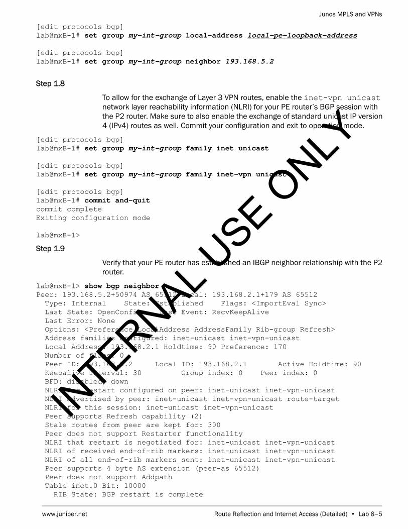
Junos MPLS and VPNs
www.juniper.net Route Reflection and Internet Access (Detailed) • Lab 8–5
[edit protocols bgp]lab@mxB-1# set group my-int-group local-address local-pe-loopback-address
[edit protocols bgp]lab@mxB-1# set group my-int-group neighbor 193.168.5.2
Step 1.8
To allow for the exchange of Layer 3 VPN routes, enable the inet-vpn unicast network layer reachability information (NLRI) for your PE router’s BGP session with the P2 router. Make sure to also enable the exchange of standard unicast IP version 4 (IPv4) routes as well. Commit your configuration and exit to operation mode.
[edit protocols bgp]lab@mxB-1# set group my-int-group family inet unicast
[edit protocols bgp]lab@mxB-1# set group my-int-group family inet-vpn unicast
[edit protocols bgp]lab@mxB-1# commit and-quit commit completeExiting configuration mode
lab@mxB-1>
Step 1.9
Verify that your PE router has established an IBGP neighbor relationship with the P2 router.
lab@mxB-1> show bgp neighborPeer: 193.168.5.2+50974 AS 65512 Local: 193.168.2.1+179 AS 65512 Type: Internal State: Established Flags: <ImportEval Sync> Last State: OpenConfirm Last Event: RecvKeepAlive Last Error: None Options: <Preference LocalAddress AddressFamily Rib-group Refresh> Address families configured: inet-unicast inet-vpn-unicast Local Address: 193.168.2.1 Holdtime: 90 Preference: 170 Number of flaps: 0 Peer ID: 193.168.5.2 Local ID: 193.168.2.1 Active Holdtime: 90 Keepalive Interval: 30 Group index: 0 Peer index: 0 BFD: disabled, down NLRI for restart configured on peer: inet-unicast inet-vpn-unicast NLRI advertised by peer: inet-unicast inet-vpn-unicast route-target NLRI for this session: inet-unicast inet-vpn-unicast Peer supports Refresh capability (2) Stale routes from peer are kept for: 300 Peer does not support Restarter functionality NLRI that restart is negotiated for: inet-unicast inet-vpn-unicast NLRI of received end-of-rib markers: inet-unicast inet-vpn-unicast NLRI of all end-of-rib markers sent: inet-unicast inet-vpn-unicast Peer supports 4 byte AS extension (peer-as 65512) Peer does not support Addpath Table inet.0 Bit: 10000 RIB State: BGP restart is complete
INTERNAL U
SE ONLY

Junos MPLS and VPNs
Lab 8–6 • Route Reflection and Internet Access (Detailed) www.juniper.net
Send state: in sync Active prefixes: 0 Received prefixes: 0 Accepted prefixes: 0 Suppressed due to damping: 0 Advertised prefixes: 0 Table bgp.l3vpn.0 RIB State: BGP restart is complete RIB State: VPN restart is complete Send state: not advertising Active prefixes: 0 Received prefixes: 0 Accepted prefixes: 0 Suppressed due to damping: 0 Last traffic (seconds): Received 12 Sent 6 Checked 36 Input messages: Total 5 Updates 2 Refreshes 0 Octets 166 Output messages: Total 4 Updates 0 Refreshes 0 Octets 177 Output Queue[0]: 0 Output Queue[1]: 0
Question: Is the neighbor relationship in the established state with the P2 router?
Answer: The P2 router should be in an established state with your PE router. If it is not, double check the interface and BGP settings. If you need further assistance, consult with your instructor.
Question: What NLRI type has been negotiated between your PE router and the P2 router?
Answer: Using the show bgp neighbor command, you should see that the NLRI for this session should be inet-unicast and inet-vpn-unicast.
Step 1.10
For an interface to support the forwarding of MPLS packets, you must enable the MPLS family on each interface. Enter configuration mode and navigate to the [edit interfaces] hierarchy and enable family mpls on both of the core-facing interfaces.
lab@mxB-1> configure Entering configuration mode
INTERNAL U
SE ONLY

Junos MPLS and VPNs
www.juniper.net Route Reflection and Internet Access (Detailed) • Lab 8–7
[edit]lab@mxB-1# edit interfaces
[edit interfaces]lab@mxB-1# set ge-1/0/0 unit unit family mpls
[edit interfaces]lab@mxB-1# set ge-1/0/1 unit unit family mpls
[edit interfaces]lab@mxB-1
Step 1.11
Navigate to the [edit protocols] hierarchy and configure the MPLS protocol on the core-facing interfaces.
[edit interfaces]lab@mxB-1# top edit protocols
[edit protocols]lab@mxB-1# set mpls interface ge-1/0/0.unit
[edit protocols]lab@mxB-1# set mpls interface ge-1/0/1.unit
[edit protocols]lab@mxB-1#
Step 1.12
Configure the LDP protocol on the core-facing interfaces as well as the loopback interface.
[edit protocols]lab@mxB-1# set ldp interface ge-1/0/0.unit
[edit protocols]lab@mxB-1# set ldp interface ge-1/0/1.unit
[edit protocols]lab@mxB-1# set ldp interface lo0.0
Step 1.13
To allow for the automatic generation of route distinguishers, navigate to the [edit routing-options] hierarchy and specify the route-distinguisher-id using your PE router’s loopback address. Commit your configuration and exit out to operational mode.
[edit protocols]lab@mxB-1# top edit routing-options
[edit routing-options]lab@mxB-1# set route-distinguisher-id local-pe-loopback-address
[edit routing-options]lab@mxB-1# commit and-quit
INTERNAL U
SE ONLY

Junos MPLS and VPNs
Lab 8–8 • Route Reflection and Internet Access (Detailed) www.juniper.net
commit completeExiting configuration mode
lab@mxB-1>
Step 1.14
Use the show mpls interface command to verify that MPLS is configured correctly on the core-facing interfaces.
lab@mxB-1> show mpls interface Interface State Administrative groups (x: extended)ge-1/0/0.220 Up <none>ge-1/0/1.221 Up <none>
Question: Can your core-facing interfaces now support the transmission of MPLS packets?
Answer: The output of the command shows that the two interfaces can now support the forwarding of MPLS packets.
Step 1.15
Verify that your router has established LDP neighbor relationships with the neighboring P routers.
lab@mxB-1> show ldp neighbor Address Interface Label space ID Hold time172.22.220.2 ge-1/0/0.220 193.168.5.1:0 13172.22.221.2 ge-1/0/1.221 193.168.5.4:0 10
lab@mxB-1> show ldp session Address State Connection Hold time Adv. Mode193.168.5.1 Operational Open 23 DU193.168.5.4 Operational Open 23 DU
Question: What is the state of your PE router’s relationship with the neighboring P routers?
Answer: The neighboring P routers should be in the Operational state with your PE router.
Step 1.16
Verify that the inet.3 routing table contains an LDP route to the remote PE router.
lab@mxB-1> show route table inet.3
inet.3: 7 destinations, 7 routes (7 active, 0 holddown, 0 hidden)+ = Active Route, - = Last Active, * = Both
INTERNAL U
SE ONLY

Junos MPLS and VPNs
www.juniper.net Route Reflection and Internet Access (Detailed) • Lab 8–9
193.168.2.2/32 *[LDP/9] 00:06:41, metric 1 > to 172.22.221.2 via ge-1/0/1.221, Push 300064 to 172.22.220.2 via ge-1/0/0.220, Push 300096193.168.5.1/32 *[LDP/9] 00:06:41, metric 1 > to 172.22.220.2 via ge-1/0/0.220193.168.5.2/32 *[LDP/9] 00:06:41, metric 1 > to 172.22.220.2 via ge-1/0/0.220, Push 299840193.168.5.3/32 *[LDP/9] 00:06:41, metric 1 > to 172.22.220.2 via ge-1/0/0.220, Push 299824193.168.5.4/32 *[LDP/9] 00:06:41, metric 1 > to 172.22.221.2 via ge-1/0/1.221193.168.5.5/32 *[LDP/9] 00:06:41, metric 1 > to 172.22.221.2 via ge-1/0/1.221, Push 299776193.168.5.6/32 *[LDP/9] 00:06:41, metric 1 > to 172.22.221.2 via ge-1/0/1.221, Push 299792
Question: Do you see the LDP route to the remote PE router in your inet.3 routing table?
Answer: Yes, you should see the LDP route in the inet.3 routing table now. If you do not, please review your configuration and verify the state of your MPLS LSP is Up.
STOP Do not proceed until the remote team finishes Part 1.
Part 2: Verifying CE Router Configuration
In this lab part, you will view the configuration for the two CE routers (logical systems) that were preconfigured as part of the loaded starting configuration in Part 1 of this lab.
Step 2.1
Use the set cli logical-system command to place the CLI in the context of the lower CE router logical system (based on the location on diagram).
lab@mxB-1> set cli logical-system lower-ce-hostname Logical system: ceB-1
lab@mxB-1:ceB-1>
Step 2.2
Issue the show configuration command to view the configuration of the CE router.
lab@mxB-1:ceB-1> show configuration interfaces { ge-1/1/4 { unit 620 {
INTERNAL U
SE ONLY

Junos MPLS and VPNs
Lab 8–10 • Route Reflection and Internet Access (Detailed) www.juniper.net
vlan-id 620; family inet { address 10.0.20.2/24; } } } lo0 { unit 1 { family inet { address 193.168.12.1/32; } } }}policy-options { policy-statement exp-policy { term 10 { from protocol static; then accept; } term 20 { from protocol direct; then accept; } }}routing-options { static { route 172.20.0.0/24 reject; route 172.20.1.0/24 reject; route 172.20.2.0/24 reject; route 172.20.3.0/24 reject; } autonomous-system 65201;}
lab@mxB-1:ceB-1>
Question: What interfaces have been configured on the CE router? According to the lab diagram, do they have the appropriate IP addressing?
Answer: The CE router should have both the loopback and ge-1/1/4 interface configured with the appropriate addressing according to the lab diagram.
INTERNAL U
SE ONLY

Junos MPLS and VPNs
www.juniper.net Route Reflection and Internet Access (Detailed) • Lab 8–11
Question: What is configured under the routing-options hierarchy? According to the lab diagram, are these setting appropriate?
Answer: Four static routes (next hop of reject) and the CE router’s autonomous system should be configured under routing-options hierarchy. These settings are appropriate.
Question: What is configured under the policy-options hierarchy? What does this policy do?
Answer: A policy called exp-policy is configured under policy-options hierarchy. If applied as an export policy, this policy will redistribute active direct and static routes into the protocol to which it is applied. It is currently not applied to any protocol in the configuration.
Step 2.3
Use the ping utility to attempt to ping the local PE router’s ge-1/0/4 interface.
lab@mxB-1:ceB-1> ping local-pe-address count 1 PING 10.0.20.1 (10.0.20.1): 56 data bytes
--- 10.0.20.1 ping statistics ---1 packets transmitted, 0 packets received, 100% packet loss
Question: Does your ping succeed? Why?
Answer: The pings do not succeed because the PE router’s ge-1/0/4 interface has not been configured at this point in the lab.
Step 2.4
Use the set cli logical-system command to place the CLI in the context of the upper CE router logical system (based on the location on diagram).
lab@mxB-1:ceB-1> set cli logical-system upper-ce-hostname Logical system: ceB-3
lab@mxB-1:ceB-3>
INTERNAL U
SE ONLY

Junos MPLS and VPNs
Lab 8–12 • Route Reflection and Internet Access (Detailed) www.juniper.net
Step 2.5
Issue the show configuration command to view the configuration of the CE router.
lab@mxB-1:ceB-3> show configuration interfaces { ge-1/1/5 { unit 621 { vlan-id 621; family inet { address 10.1.20.2/24; } } } lo0 { unit 2 { family inet { address 193.168.22.1/32; } } }}policy-options { policy-statement exp-policy { term 10 { from protocol static; then accept; } term 20 { from protocol direct; then accept; } }}routing-options { static { route 172.21.0.0/24 reject; route 172.21.1.0/24 reject; route 172.21.2.0/24 reject; route 172.21.3.0/24 reject; } autonomous-system 65202;}
lab@mxB-1:ceB-3> INTERNAL U
SE ONLY

Junos MPLS and VPNs
www.juniper.net Route Reflection and Internet Access (Detailed) • Lab 8–13
Question: What interfaces have been configured on the CE router? According to the lab diagram, do they have the appropriate IP addressing?
Answer: The CE router should have both the loopback and ge-1/1/5 interface configured with the appropriate addressing according to the lab diagram.
Question: What is configured under the routing-options hierarchy? According to the lab diagram, are these setting appropriate?
Answer: Four static routes (next hop of reject) and the CE router’s autonomous system should be configured under routing-options hierarchy. These settings are appropriate.
Question: What is configured under the policy-options hierarchy? What does this policy do?
Answer: A policy called exp-policy is configured under policy-options hierarchy. If applied as an export policy, this policy will redistribute active direct and static routes into the protocol to which it is applied. It is currently not applied to any protocol in the configuration.
Step 2.6
Use the ping utility to attempt to ping the local PE router’s ge-1/0/5 interface.
lab@mxB-1:ceB-3> ping local-pe-address count 1 PING 10.1.20.1 (10.1.20.1): 56 data bytes
--- 10.1.20.1 ping statistics ---1 packets transmitted, 0 packets received, 100% packet loss
INTERNAL U
SE ONLY

Junos MPLS and VPNs
Lab 8–14 • Route Reflection and Internet Access (Detailed) www.juniper.net
Question: Does your ping succeed? Why?
Answer: The pings do not succeed because the PE router’s ge-1/0/5 interface has not been configured at this point in the lab.
Part 3: Configuring the PE to CE Interfaces
In this lab part, you will configure both of the PE to CE interfaces.You will verify reachability using the ping utility.
Step 3.1
Issue the clear cli logical-system to return to the CLI context of the default routing instance (your PE router).
lab@mxB-1:ceB-3> clear cli logical-system Cleared default logical system
lab@mxB-1>
Step 3.2
Enter into configuration mode and navigate to the [edit interfaces] hierarchy. Configure the appropriate interface properties on your PE routers that can be found on the lab diagram. You will configure the interfaces for each connection to the two CE routers. Commit your change and exit to operational mode to verify reachability to the CE interface.
lab@mxB-1> configure Entering configuration mode
[edit]lab@mxB-1# edit interfaces
[edit interfaces]lab@mxB-1# set ge-1/0/4 vlan-tagging unit unit vlan-id vlan-id
[edit interfaces]lab@mxB-1# set ge-1/0/4 unit unit family inet address address/24
[edit interfaces]lab@mxB-1# set ge-1/0/5 vlan-tagging unit unit vlan-id vlan-id
[edit interfaces]lab@mxB-1# set ge-1/0/5 unit unit family inet address address/24
INTERNAL U
SE ONLY

Junos MPLS and VPNs
www.juniper.net Route Reflection and Internet Access (Detailed) • Lab 8–15
[edit interfaces]lab@mxB-1# commit and-quit commit completeExiting configuration mode
lab@mxB-1>
Step 3.3
Verify reachability to both CE routers by pinging their interfaces five times.
lab@mxB-1> ping lower-ce-address count 5 PING 10.0.20.2 (10.0.20.2): 56 data bytes64 bytes from 10.0.20.2: icmp_seq=0 ttl=64 time=7.201 ms64 bytes from 10.0.20.2: icmp_seq=1 ttl=64 time=0.598 ms64 bytes from 10.0.20.2: icmp_seq=2 ttl=64 time=0.550 ms64 bytes from 10.0.20.2: icmp_seq=3 ttl=64 time=0.576 ms64 bytes from 10.0.20.2: icmp_seq=4 ttl=64 time=0.558 ms
--- 10.0.20.2 ping statistics ---5 packets transmitted, 5 packets received, 0% packet lossround-trip min/avg/max/stddev = 0.550/1.897/7.201/2.652 ms
lab@mxB-1> ping upper-ce-address count 5 PING 10.1.20.2 (10.1.20.2): 56 data bytes64 bytes from 10.1.20.2: icmp_seq=0 ttl=64 time=6.616 ms64 bytes from 10.1.20.2: icmp_seq=1 ttl=64 time=4.930 ms64 bytes from 10.1.20.2: icmp_seq=2 ttl=64 time=3.992 ms64 bytes from 10.1.20.2: icmp_seq=3 ttl=64 time=7.623 ms64 bytes from 10.1.20.2: icmp_seq=4 ttl=64 time=12.433 ms
--- 10.1.20.2 ping statistics ---5 packets transmitted, 5 packets received, 0% packet lossround-trip min/avg/max/stddev = 3.992/7.119/12.433/2.943 ms
Question: Do the pings complete?
Answer: Yes, your ping tests should complete to both CE routers. If they do not, check your configuration of both the CE and PE interfaces to ensure you have configured the properties correctly. Please request assistance from the instructor, if needed.IN
TERNAL USE O
NLY

Junos MPLS and VPNs
Lab 8–16 • Route Reflection and Internet Access (Detailed) www.juniper.net
Part 4: Configuring Two Layer 3 VPN Instances
In this lab part, you will configure two Layer 3 VPN instances. You will create a VPN named vpn-lower, which will connect the lower CE routers (see diagram) of the two sites. For example, if you are controlling mxB-1 or mxB-2 (pod B), you will create a VPN that connects ceB-1 to ceB-2. You will then create a VPN named vpn-upper, which will connect the upper CE routers. You will assign a unique route target to each instance and you will include your CE-facing interface within the appropriate instance. In this lab, you will be using the vrf-target option because of its simplicity. Please note that vrf-import and vrf-export policies would work also. Use the following table as your guide for configuring your target communities in this part of the lab.
Step 4.1
Enter into configuration mode and navigate to the [edit routing-instances vpn-lower] hierarchy. Configure the routing instance specifying a routing instance type of vrf.
lab@mxB-1> configure Entering configuration mode
[edit]lab@mxB-1# edit routing-instances vpn-lower
[edit routing-instances vpn-lower]lab@mxB-1# set instance-type vrf
[edit routing-instances vpn-lower]lab@mxB-1#
Step 4.2
Configure your route target for the lower VPN. As mentioned previously, you will be using the vrf-target option. See the table at the beginning of this part of the lab to determine the appropriate target community value.
[edit routing-instances vpn-lower]lab@mxB-1# set vrf-target lower-target-value
Step 4.3
Configure the vrf-table-label behavior for this VRF instance.
[edit routing-instances vpn-lower]lab@mxB-1# set vrf-table-label
Pod Lower Target Upper Target
A target:65512:101 target:65512:102
B target:65512:201 target:65512:202
C target:65512:301 target:65512:302
D target:65512:401 target:65512:402
INTERNAL U
SE ONLY

Junos MPLS and VPNs
www.juniper.net Route Reflection and Internet Access (Detailed) • Lab 8–17
Step 4.4
Add the appropriate subinterface of ge-1/0/4 to the routing instance. Review your configuration changes and commit when you are satisfied with the changes.
[edit routing-instances vpn-lower]lab@mxB-1# set interface ge-1/0/4.unit
[edit routing-instances vpn-lower]lab@mxB-1# show instance-type vrf;interface ge-1/0/4.620;vrf-target target:65512:201;vrf-table-label;
[edit routing-instances vpn-lower]lab@mxB-1# commit commit complete
Step 4.5
Navigate to the [edit routing-instances vpn-upper] hierarchy. Configure the routing instance specifying a routing instance type of vrf.
[edit routing-instances vpn-lower]lab@mxB-1# up
[edit routing-instances]lab@mxB-1# edit vpn-upper
[edit routing-instances vpn-upper]lab@mxB-1# set instance-type vrf
[edit routing-instances vpn-upper]lab@mxB-1#
Step 4.6
Configure your route target for the upper VPN using the vrf-target option. See the table at the beginning of this part of the lab to determine the appropriate target community value.
[edit routing-instances vpn-upper]lab@mxB-1# set vrf-target upper-target-value
Step 4.7
Add the appropriate subinterface of ge-1/0/5 to the routing instance. Review your configuration changes and when satisfied, commit and exit to operational mode.
[edit routing-instances vpn-upper]lab@mxB-1# set interface ge-1/0/5.unit
[edit routing-instances vpn-upper]lab@mxB-1# show instance-type vrf;interface ge-1/0/5.621;vrf-target target:65512:202;
INTERNAL U
SE ONLY
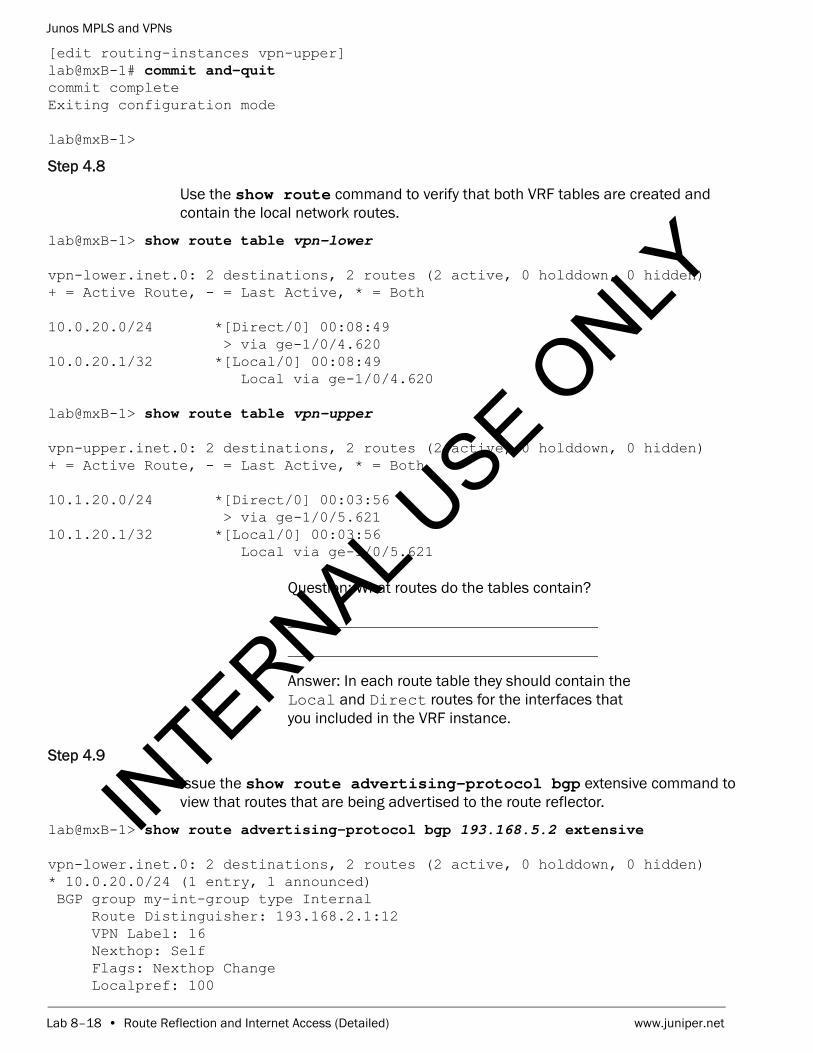
Junos MPLS and VPNs
Lab 8–18 • Route Reflection and Internet Access (Detailed) www.juniper.net
[edit routing-instances vpn-upper]lab@mxB-1# commit and-quit commit completeExiting configuration mode
lab@mxB-1>
Step 4.8
Use the show route command to verify that both VRF tables are created and contain the local network routes.
lab@mxB-1> show route table vpn-lower
vpn-lower.inet.0: 2 destinations, 2 routes (2 active, 0 holddown, 0 hidden)+ = Active Route, - = Last Active, * = Both
10.0.20.0/24 *[Direct/0] 00:08:49 > via ge-1/0/4.62010.0.20.1/32 *[Local/0] 00:08:49 Local via ge-1/0/4.620
lab@mxB-1> show route table vpn-upper
vpn-upper.inet.0: 2 destinations, 2 routes (2 active, 0 holddown, 0 hidden)+ = Active Route, - = Last Active, * = Both
10.1.20.0/24 *[Direct/0] 00:03:56 > via ge-1/0/5.62110.1.20.1/32 *[Local/0] 00:03:56 Local via ge-1/0/5.621
Question: What routes do the tables contain?
Answer: In each route table they should contain the Local and Direct routes for the interfaces that you included in the VRF instance.
Step 4.9
Issue the show route advertising-protocol bgp extensive command to view that routes that are being advertised to the route reflector.
lab@mxB-1> show route advertising-protocol bgp 193.168.5.2 extensive
vpn-lower.inet.0: 2 destinations, 2 routes (2 active, 0 holddown, 0 hidden)* 10.0.20.0/24 (1 entry, 1 announced) BGP group my-int-group type Internal Route Distinguisher: 193.168.2.1:12 VPN Label: 16 Nexthop: Self Flags: Nexthop Change Localpref: 100
INTERNAL U
SE ONLY

Junos MPLS and VPNs
www.juniper.net Route Reflection and Internet Access (Detailed) • Lab 8–19
AS path: [65512] I Communities: target:65512:201
vpn-upper.inet.0: 2 destinations, 2 routes (2 active, 0 holddown, 0 hidden)
* 10.1.20.0/24 (1 entry, 1 announced) BGP group my-int-group type Internal Route Distinguisher: 193.168.2.1:13 BGP label allocation failure: Need a nexthop address on LAN Nexthop: Not advertised Flags: Nexthop Change Localpref: 100 AS path: [65512] I Communities: target:65512:202
Question: Do you notice any differences in the routes in the vpn-lower and vpn-upper tables? Why?
Answer: The route in the vpn-upper table is not being advertised because the PE has not learned any route from the attached CE. By default, a Juniper router maps and allocates VPN labels to a next hop. Without a learned next-hop, a label cannot be allocated. The route in the vpn-lower table is being advertised since you configured vrf-table-label causing the router to allocate VPN labels on a per table basis (there is no longer a need to pre-determine the next hop before label allocation).
STOP Do not proceed until the remote team finishes Part 6.
Part 5: Configuring BGP Routing Between the PE and CE Routers
In this lab part, you will configure BGP routing to pass routes from your CE routers to your PE router. These routes will be passed through the MP-BGP session to the remote PE router so that traffic can be routed from the remote CE sites. You will verify that your routes are shared with the remote PE device and you will also need to verify that you are receiving the routes from the remote PE router for each of the configured VPNs. You will use the ping utility to test the CE to CE connectivity over the Layer 3 VPNs for each site.
INTERNAL U
SE ONLY

Junos MPLS and VPNs
Lab 8–20 • Route Reflection and Internet Access (Detailed) www.juniper.net
Step 5.1
Enter into configuration mode and navigate to the [edit routing-instances vpn-lower protocols bgp] hierarchy. Create an external group called my-ext-group-lower and specify your locally attached CE router’s neighbor address. You must also define your peer-as. Remember to add the option as-override to your BGP group, because both the local CE router and the remote CE router are in the same AS. Review your configuration, commit, and exit to operation mode before moving on to the next step.
lab@mxB-1> configure Entering configuration mode
[edit]lab@mxB-1# edit routing-instances vpn-lower protocols bgp
[edit routing-instances vpn-lower protocols bgp]lab@mxB-1# set group my-ext-group-lower type external
[edit routing-instances vpn-lower protocols bgp]lab@mxB-1# set group my-ext-group-lower neighbor lower-ce-address
[edit routing-instances vpn-lower protocols bgp]lab@mxB-1# set group my-ext-group-lower peer-as lower-ce-as-number
[edit routing-instances vpn-lower protocols bgp]lab@mxB-1# set group my-ext-group-lower as-override
[edit routing-instances vpn-lower protocols bgp]lab@mxB-1# show group my-ext-group-lower { type external; peer-as 65201; as-override; neighbor 10.0.20.2;}
[edit routing-instances vpn-lower protocols bgp]lab@mxB-1# commit and-quit commit completeExiting configuration mode
lab@mxB-1>
Step 5.2
Use the set cli logical-system command to place the CLI in the context of the lower CE router logical system (based on the location on diagram).
lab@mxB-1> set cli logical-system lower-ce-hostname Logical system: ceB-1
lab@mxB-1:ceB-1>
INTERNAL U
SE ONLY

Junos MPLS and VPNs
www.juniper.net Route Reflection and Internet Access (Detailed) • Lab 8–21
Step 5.3
Enter configuration mode and navigate to the [edit protocols bgp] hierarchy. Create an external group called my-ext-group and specify your local PE router’s neighbor address. You must also define your peer-as. Apply the policy exp-policy that you viewed earlier in the lab as an export policy to your EBGP group. Review your configuration, commit, and exit to operational mode.
lab@mxB-1:ceB-1> configure Entering configuration mode
[edit]lab@mxB-1:ceB-1# edit protocols bgp
[edit protocols bgp]lab@mxB-1:ceB-1# set group my-ext-group type external
[edit protocols bgp]lab@mxB-1:ceB-1# set group my-ext-group neighbor local-pe-address
[edit protocols bgp]lab@mxB-1:ceB-1# set group my-ext-group peer-as 65512
[edit protocols bgp]lab@mxB-1:ceB-1# set group my-ext-group export exp-policy
[edit protocols bgp]lab@mxB-1:ceB-1# show group my-ext-group { type external; export exp-policy; peer-as 65512; neighbor 10.0.20.1;}
[edit protocols bgp]lab@mxB-1:ceB-1# commit and-quit commit completeExiting configuration mode
lab@mxB-1:ceB-1>
Step 5.4
Issue the clear cli logical-system to return to the CLI context of the default routing instance (your PE router).
Note
Check with the team configuring the remote CE router and ensure that they have completed Step 5.3 before proceeding to the next step.
INTERNAL U
SE ONLY

Junos MPLS and VPNs
Lab 8–22 • Route Reflection and Internet Access (Detailed) www.juniper.net
lab@mxB-1:ceB-1> clear cli logical-system Cleared default logical system
lab@mxB-1>
Step 5.5
Use the show route receive-protocol bgp command to verify that you are receiving the static routes from the lower CE router at your PE router.
lab@mxB-1> show route receive-protocol bgp lower-ce-address
inet.0: 33 destinations, 33 routes (33 active, 0 holddown, 0 hidden)
inet.3: 7 destinations, 7 routes (7 active, 0 holddown, 0 hidden)
vpn-lower.inet.0: 13 destinations, 14 routes (13 active, 0 holddown, 0 hidden) Prefix Nexthop MED Lclpref AS path 10.0.20.0/24 10.0.20.2 65201 I* 172.20.0.0/24 10.0.20.2 65201 I* 172.20.1.0/24 10.0.20.2 65201 I* 172.20.2.0/24 10.0.20.2 65201 I* 172.20.3.0/24 10.0.20.2 65201 I* 193.168.12.1/32 10.0.20.2 65201 I
vpn-upper.inet.0: 8 destinations, 8 routes (8 active, 0 holddown, 0 hidden)
mpls.0: 14 destinations, 14 routes (14 active, 0 holddown, 0 hidden)
bgp.l3vpn.0: 12 destinations, 12 routes (12 active, 0 holddown, 0 hidden)
Question: Has your PE router received the BGP routes that represent that static routes that were redistributed by the local, lower CE router?
Answer: Your PE router should be receiving the routes from the local, lower CE router.
Step 5.6
Issue the show route advertising-protocol bgp 193.168.5.2 command to verify that you are sending the routes learned from the local lower CE router to the remote team through the route reflector.
lab@mxB-1> show route advertising-protocol bgp 193.168.5.2
vpn-lower.inet.0: 13 destinations, 14 routes (13 active, 0 holddown, 0 hidden) Prefix Nexthop MED Lclpref AS path* 10.0.20.0/24 Self 100 I* 172.20.0.0/24 Self 100 65201 I* 172.20.1.0/24 Self 100 65201 I* 172.20.2.0/24 Self 100 65201 I* 172.20.3.0/24 Self 100 65201 I
INTERNAL U
SE ONLY

Junos MPLS and VPNs
www.juniper.net Route Reflection and Internet Access (Detailed) • Lab 8–23
* 193.168.12.1/32 Self 100 65201 I
vpn-upper.inet.0: 8 destinations, 8 routes (8 active, 0 holddown, 0 hidden) Prefix Nexthop MED Lclpref AS path* 10.1.20.0/24 Not advertised 100 I
Question: Is your PE router sending the BGP routes that represent that static routes that were redistributed by the local, lower CE router?
Answer: Your PE router should be sending the routes to the route reflector.
Step 5.7
Issue the show route receive-protocol bgp 193.168.5.2 command to verify that you are also receiving the remote, lower CE router’s static routes at your PE router from the route reflector.
lab@mxB-1> show route receive-protocol bgp 193.168.5.2
inet.0: 33 destinations, 33 routes (33 active, 0 holddown, 0 hidden)
inet.3: 7 destinations, 7 routes (7 active, 0 holddown, 0 hidden)
vpn-lower.inet.0: 13 destinations, 14 routes (13 active, 0 holddown, 0 hidden) Prefix Nexthop MED Lclpref AS path* 10.0.21.0/24 193.168.2.2 100 I* 172.10.4.0/24 193.168.2.2 100 65201 I* 172.10.5.0/24 193.168.2.2 100 65201 I* 172.10.6.0/24 193.168.2.2 100 65201 I* 172.10.7.0/24 193.168.2.2 100 65201 I* 193.168.12.2/32 193.168.2.2 100 65201 I...
Question: Is your PE router receiving the BGP routes that represent that static routes that were redistributed by the remote, lower CE router?
Answer: Your PE router should be receiving the routes from the route reflector.
Step 5.8
Issue the show route advertising-protocol bgp local-ce-address command to verify that you are sending the routes learned from the remote, lower CE router to the local, lower CE router.
INTERNAL U
SE ONLY

Junos MPLS and VPNs
Lab 8–24 • Route Reflection and Internet Access (Detailed) www.juniper.net
lab@mxB-1> show route advertising-protocol bgp lower-ce-address
vpn-lower.inet.0: 13 destinations, 14 routes (13 active, 0 holddown, 0 hidden) Prefix Nexthop MED Lclpref AS path* 10.0.21.0/24 Self I* 172.20.0.0/24 10.0.20.2 65512 I* 172.20.1.0/24 10.0.20.2 65512 I* 172.20.2.0/24 10.0.20.2 65512 I* 172.20.3.0/24 10.0.20.2 65512 I* 172.20.4.0/24 Self 65512 I* 172.20.5.0/24 Self 65512 I* 172.20.6.0/24 Self 65512 I* 172.20.7.0/24 Self 65512 I* 193.168.12.1/32 10.0.20.2 65512 I* 193.168.12.2/32 Self 65512 I
Question: Is your PE router sending the BGP routes from the remote, lower CE router to the local, lower CE router?
Answer: Your PE router should be sending the routes to the local, lower CE router.
Step 5.9
Use the set cli logical-system command to place the CLI in the context of the lower CE router logical system (based on the location on diagram).
lab@mxB-1> set cli logical-system lower-ce-hostname Logical system: ceB-1
lab@mxB-1:ceB-1>
Step 5.10
Verify reachability to the remote CE router by pinging the loopback address five times. This task can be accomplished by issuing the ping remote-ce-loopback source local-ce-loopback count 5 command.
lab@mxB-1:ceB-1> ping remote-ce-loopback source local-ce-loopback count 5 PING 193.168.12.2 (193.168.12.2): 56 data bytes64 bytes from 193.168.12.2: icmp_seq=0 ttl=59 time=0.853 ms64 bytes from 193.168.12.2: icmp_seq=1 ttl=59 time=0.844 ms64 bytes from 193.168.12.2: icmp_seq=2 ttl=59 time=0.734 ms64 bytes from 193.168.12.2: icmp_seq=3 ttl=59 time=0.802 ms64 bytes from 193.168.12.2: icmp_seq=4 ttl=59 time=0.766 ms
--- 193.168.12.2 ping statistics ---5 packets transmitted, 5 packets received, 0% packet lossround-trip min/avg/max/stddev = 0.734/0.800/0.853/0.045 ms
INTERNAL U
SE ONLY

Junos MPLS and VPNs
www.juniper.net Route Reflection and Internet Access (Detailed) • Lab 8–25
Question: Did the ping test complete?
Answer: Yes, your pings should complete.
Step 5.11
Issue the clear cli logical-system to return to the CLI context of the default routing instance (your PE router).
lab@mxB-1:ceB-1> clear cli logical-system Cleared default logical system
lab@mxB-1>
Step 5.12
Enter into configuration mode and navigate to the [edit routing-instances vpn-upper protocols bgp] hierarchy. Create an external group named my-ext-group-upper and specify your neighbor address. You must also define your peer-as. Remember to add the option as-override to your BGP group, because both the local CE router and the remote CE router are in the same AS. Review your configuration, commit your configuration, and exit to operational mode before proceeding to the next step.
lab@mxB-1> configure Entering configuration mode
[edit]lab@mxB-1# edit routing-instances vpn-upper protocols bgp
[edit routing-instances vpn-upper protocols bgp]lab@mxB-1# set group my-ext-group-upper type external
[edit routing-instances vpn-upper protocols bgp]lab@mxB-1# set group my-ext-group-upper neighbor upper-ce-address
[edit routing-instances vpn-upper protocols bgp]lab@mxB-1# set group my-ext-group-upper peer-as upper-ce-as-number
[edit routing-instances vpn-upper protocols bgp]lab@mxB-1# set group my-ext-group-upper as-override
[edit routing-instances vpn-upper protocols bgp]lab@mxB-1# show group my-ext-group-upper {
Note
If you are not receiving or sending any of the routes from the previous steps, please review your configuration and work with the remote team for your pod. Request assistance from the instructor as needed.
INTERNAL U
SE ONLY

Junos MPLS and VPNs
Lab 8–26 • Route Reflection and Internet Access (Detailed) www.juniper.net
type external; peer-as 65202; as-override; neighbor 10.1.20.2;}
[edit routing-instances vpn-upper protocols bgp]lab@mxB-1# commit and-quit commit completeExiting configuration mode
lab@mxB-1>
Step 5.13
Use the set cli logical-system command to place the CLI in the context of the upper CE router logical system (based on the location on diagram).
lab@mxB-1> set cli logical-system upper-ce-router Logical system: ceB-3
lab@mxB-1:ceB-3>
Step 5.14
Enter configuration mode and navigate to the [edit protocols bgp] hierarchy. Create an external group named my-ext-group and specify your neighbor address. You must also define your peer-as. Apply the policy exp-policy that you viewed earlier in this lab as an export policy to your EBGP group. Review your configuration, commit, and exit to operational mode.
lab@mxB-1:ceB-3> configure Entering configuration mode
[edit]lab@mxB-1:ceB-3# edit protocols bgp
[edit protocols bgp]lab@mxB-1:ceB-3# set group my-ext-group neighbor local-pe-address
[edit protocols bgp]lab@mxB-1:ceB-3# set group my-ext-group type external
[edit protocols bgp]lab@mxB-1:ceB-3# set group my-ext-group peer-as 65512
[edit protocols bgp]lab@mxB-1:ceB-3# set group my-ext-group export exp-policy
[edit protocols bgp]lab@mxB-1:ceB-3# show group my-ext-group { type external; export exp-policy; peer-as 65512; neighbor 10.1.20.1;}
INTERNAL U
SE ONLY

Junos MPLS and VPNs
www.juniper.net Route Reflection and Internet Access (Detailed) • Lab 8–27
[edit protocols bgp]lab@mxB-1:ceB-3# commit and-quit commit completeExiting configuration mode
lab@mxB-1:ceB-3>
Step 5.15
Issue the clear cli logical-system to return to the CLI context of the default routing instance (your PE router).
lab@mxB-1:ceB-3> clear cli logical-system Cleared default logical system
lab@mxB-1>
Step 5.16
Use the show route receive-protocol bgp command to verify that you are receiving the static routes from the upper, local CE router at your PE router.
lab@mxB-1> show route receive-protocol bgp upper-ce-address
inet.0: 33 destinations, 33 routes (33 active, 0 holddown, 0 hidden)
inet.3: 7 destinations, 7 routes (7 active, 0 holddown, 0 hidden)
vpn-lower.inet.0: 13 destinations, 14 routes (13 active, 0 holddown, 0 hidden)
vpn-upper.inet.0: 13 destinations, 14 routes (13 active, 0 holddown, 0 hidden) Prefix Nexthop MED Lclpref AS path 10.1.20.0/24 10.1.20.2 65202 I* 172.21.0.0/24 10.1.20.2 65202 I* 172.21.1.0/24 10.1.20.2 65202 I* 172.21.2.0/24 10.1.20.2 65202 I* 172.21.3.0/24 10.1.20.2 65202 I* 193.168.22.1/32 10.1.20.2 65202 I
mpls.0: 15 destinations, 15 routes (15 active, 0 holddown, 0 hidden)
bgp.l3vpn.0: 12 destinations, 12 routes (12 active, 0 holddown, 0 hidden)
Note
Check with the team configuring the remote CE router and ensure that they have completed Step 5.14 before proceeding to the next step.
INTERNAL U
SE ONLY

Junos MPLS and VPNs
Lab 8–28 • Route Reflection and Internet Access (Detailed) www.juniper.net
Question: Has your PE router received the BGP routes that represent that static routes that were redistributed by the local, upper CE router?
Answer: Your PE router should be receiving the routes from the local, upper CE router.
Step 5.17
Issue the show route advertising-protocol bgp 193.168.5.2 command to verify that you are sending the routes learned from the local, lower CE router to the remote team through the route reflector.
lab@mxB-1> show route advertising-protocol bgp 193.168.5.2
vpn-lower.inet.0: 13 destinations, 14 routes (13 active, 0 holddown, 0 hidden) Prefix Nexthop MED Lclpref AS path* 10.0.20.0/24 Self 100 I* 172.20.0.0/24 Self 100 65201 I* 172.20.1.0/24 Self 100 65201 I* 172.20.2.0/24 Self 100 65201 I* 172.20.3.0/24 Self 100 65201 I* 193.168.12.1/32 Self 100 65201 I
vpn-upper.inet.0: 13 destinations, 14 routes (13 active, 0 holddown, 0 hidden) Prefix Nexthop MED Lclpref AS path* 10.1.20.0/24 Self 100 I* 172.21.0.0/24 Self 100 65202 I* 172.21.1.0/24 Self 100 65202 I* 172.21.2.0/24 Self 100 65202 I* 172.21.3.0/24 Self 100 65202 I* 193.168.22.1/32 Self 100 65202 I
Question: Is your PE router sending the BGP routes that represent that static routes that were redistributed by the local, upper CE router?
Answer: Your PE router should be sending the routes to the route reflector.
Step 5.18
Issue the show route receive-protocol bgp 193.168.5.2 command to verify that you are also receiving the remote, upper CE router’s static routes at your PE router from the route reflector.
lab@mxB-1> show route receive-protocol bgp 193.168.5.2
inet.0: 33 destinations, 33 routes (33 active, 0 holddown, 0 hidden)
INTERNAL U
SE ONLY

Junos MPLS and VPNs
www.juniper.net Route Reflection and Internet Access (Detailed) • Lab 8–29
inet.3: 7 destinations, 7 routes (7 active, 0 holddown, 0 hidden)
vpn-lower.inet.0: 13 destinations, 14 routes (13 active, 0 holddown, 0 hidden) Prefix Nexthop MED Lclpref AS path* 10.0.21.0/24 193.168.2.2 100 I* 172.20.4.0/24 193.168.2.2 100 65201 I* 172.20.5.0/24 193.168.2.2 100 65201 I* 172.20.6.0/24 193.168.2.2 100 65201 I* 172.20.7.0/24 193.168.2.2 100 65201 I* 193.168.12.2/32 193.168.2.2 100 65201 I
vpn-upper.inet.0: 13 destinations, 14 routes (13 active, 0 holddown, 0 hidden) Prefix Nexthop MED Lclpref AS path* 10.1.21.0/24 193.168.2.2 100 I* 172.21.4.0/24 193.168.2.2 100 65202 I* 172.21.5.0/24 193.168.2.2 100 65202 I* 172.21.6.0/24 193.168.2.2 100 65202 I* 172.21.7.0/24 193.168.2.2 100 65202 I* 193.168.22.2/32 193.168.2.2 100 65202 I...
Question: Is your PE router receiving the BGP routes that represent that static routes that were redistributed by the remote, upper CE router?
Answer: Your PE router should be receiving the routes from the route reflector.
Step 5.19
Issue the show route advertising-protocol bgp upper-ce-address command to verify that you are sending the routes originated by the remote, upper CE router to the local, upper CE router.
lab@mxB-1> show route advertising-protocol bgp upper-ce-address
vpn-upper.inet.0: 13 destinations, 14 routes (13 active, 0 holddown, 0 hidden) Prefix Nexthop MED Lclpref AS path* 10.1.21.0/24 Self I* 172.21.0.0/24 10.1.20.2 65512 I* 172.21.1.0/24 10.1.20.2 65512 I* 172.21.2.0/24 10.1.20.2 65512 I* 172.21.3.0/24 10.1.20.2 65512 I* 172.21.4.0/24 Self 65512 I* 172.21.5.0/24 Self 65512 I* 172.21.6.0/24 Self 65512 I* 172.21.7.0/24 Self 65512 I* 193.168.22.1/32 10.1.20.2 65512 I* 193.168.22.2/32 Self 65512 I
INTERNAL U
SE ONLY

Junos MPLS and VPNs
Lab 8–30 • Route Reflection and Internet Access (Detailed) www.juniper.net
Question: Is your PE router sending the BGP routes originated by the remote, upper CE router to the local, upper CE router?
Answer: Your PE router should be sending the routes to the local, upper CE router.
Step 5.20
Use the set cli logical-system command to place the CLI in the context of the upper CE router logical system (based on the location on diagram).
lab@mxB-1> set cli logical-system upper-ce-hostname Logical system: ceB-3
lab@mxB-1:ceB-3>
Step 5.21
Verify reachability to the remote, upper CE router by pinging the loopback address five times. This task can be accomplished by issuing the ping remote-ce-loopback source local-ce-loopback count 5 command.
lab@mxB-1:ceB-3> ping remote-ce-loopback source local-ce-loopback count 5 PING 193.168.22.2 (193.168.22.2): 56 data bytes64 bytes from 193.168.22.2: icmp_seq=0 ttl=59 time=0.848 ms64 bytes from 193.168.22.2: icmp_seq=1 ttl=59 time=2.029 ms64 bytes from 193.168.22.2: icmp_seq=2 ttl=59 time=0.799 ms64 bytes from 193.168.22.2: icmp_seq=3 ttl=59 time=0.814 ms64 bytes from 193.168.22.2: icmp_seq=4 ttl=59 time=0.778 ms
--- 193.168.22.2 ping statistics ---5 packets transmitted, 5 packets received, 0% packet lossround-trip min/avg/max/stddev = 0.778/1.054/2.029/0.488 ms
Question: Did the ping test complete?
Answer: Yes, your pings should complete.
Note
If you are not receiving or sending any of the routes from the previous steps, please review your configuration and work with the remote team for your pod. Request assistance from the instructor as needed.
INTERNAL U
SE ONLY

Junos MPLS and VPNs
www.juniper.net Route Reflection and Internet Access (Detailed) • Lab 8–31
STOP Do not proceed until the remote team finishes Part 7.
Part 6: Implementing Route Target Filtering
In this lab part, you will implement route filtering on your PE router. You will alter the upper CE router’s vrf-target, to demonstrate the purpose of route target filtering at the route reflector. You will review the default route advertising behavior from the route reflector by utilizing the keep all option. You will configure the PE router to signal route target filtering and verify the route reflector is no longer sending you routes with target values for which your PE router is not configured.
Step 6.1
Issue the clear cli logical-system to return to the CLI context of the default routing instance (your PE router).
lab@mxB-1:ceB-3> clear cli logical-system Cleared default logical system
lab@mxB-1>
Step 6.2
Enter into configuration mode and navigate to the [edit routing-instances vpn-upper] hierarchy. Alter the vrf-target you have configured for this VPN using the table below as your guide. After making this configuration change, commit and exit to operational mode.
Pod PE Target Community
A pe1 target:65512:103
A pe2 target:65512:104
B pe1 target:65512:203
B pe2 target:65512:204
C pe1 target:65512:303
C pe2 target:65512:304
D pe1 target:65512:403
D pe2 target:65512:404IN
TERNAL USE O
NLY

Junos MPLS and VPNs
Lab 8–32 • Route Reflection and Internet Access (Detailed) www.juniper.net
lab@mxB-1> configure Entering configuration mode
[edit]lab@mxB-1# edit routing-instances vpn-upper
[edit routing-instances vpn-upper]lab@mxB-1# set vrf-target new-target-value
[edit routing-instances vpn-upper]lab@mxB-1# commit and-quit commit completeExiting configuration mode
lab@mxB-1>
Step 6.3
Review the routes that you have accepted and installed in your bgp.l3vpn.0 routing table.
lab@mxB-1> show route table bgp.l3vpn.0
bgp.l3vpn.0: 6 destinations, 6 routes (6 active, 0 holddown, 0 hidden)+ = Active Route, - = Last Active, * = Both
193.168.2.2:9:10.0.21.0/24 *[BGP/170] 03:33:01, localpref 100, from 193.168.5.2 AS path: I, validation-state: unverified to 172.22.221.2 via ge-1/0/1.221, Push 300032, Push 300064(top) > to 172.22.220.2 via ge-1/0/0.220, Push 300032, Push 300096(top)193.168.2.2:9:172.20.4.0/24 *[BGP/170] 01:31:33, localpref 100, from 193.168.5.2 AS path: 65201 I, validation-state: unverified to 172.22.221.2 via ge-1/0/1.221, Push 300032, Push 300064(top) > to 172.22.220.2 via ge-1/0/0.220, Push 300032, Push 300096(top)193.168.2.2:9:172.20.5.0/24 *[BGP/170] 01:31:33, localpref 100, from 193.168.5.2 AS path: 65201 I, validation-state: unverified to 172.22.221.2 via ge-1/0/1.221, Push 300032, Push 300064(top)
Note
Your routes will be advertised to the route reflector, but when you receive the routes for the remote CE router, your PE router will evaluate the target value against the targets configured for your VPNs and reject the routes that do not match the local target values.
INTERNAL U
SE ONLY

Junos MPLS and VPNs
www.juniper.net Route Reflection and Internet Access (Detailed) • Lab 8–33
> to 172.22.220.2 via ge-1/0/0.220, Push 300032, Push 300096(top)193.168.2.2:9:172.20.6.0/24 *[BGP/170] 01:31:33, localpref 100, from 193.168.5.2 AS path: 65201 I, validation-state: unverified to 172.22.221.2 via ge-1/0/1.221, Push 300032, Push 300064(top) > to 172.22.220.2 via ge-1/0/0.220, Push 300032, Push 300096(top)193.168.2.2:9:172.20.7.0/24 *[BGP/170] 01:31:33, localpref 100, from 193.168.5.2 AS path: 65201 I, validation-state: unverified to 172.22.221.2 via ge-1/0/1.221, Push 300032, Push 300064(top) > to 172.22.220.2 via ge-1/0/0.220, Push 300032, Push 300096(top)193.168.2.2:9:193.168.12.2/32 *[BGP/170] 03:33:01, localpref 100, from 193.168.5.2 AS path: 65201 I, validation-state: unverified > to 172.22.221.2 via ge-1/0/1.221, Push 300032, Push 300064(top) to 172.22.220.2 via ge-1/0/0.220, Push 300032, Push 300096(top)
Question: Do you see the vpn-upper routes for the remote CE router?
Answer: No, You should not see the routes since the target communities are now mismatched. You should not have routes with the prefixes advertised by the remote CE router.
Step 6.4
Enter configuration mode and navigate to the [edit protocols bgp] hierarchy. Enable the keep all functionality for your BGP session. This functionality will cause the PE router to keep all VPN routes that are advertised to it from the route reflector, regardless of vrf-target value. Commit your configuration changes and exit to operational mode.
lab@mxB-1> configure Entering configuration mode
[edit]lab@mxB-1# edit protocols bgp
[edit protocols bgp]lab@mxB-1# set keep all
[edit protocols bgp]lab@mxB-1# commit and-quit commit complete
INTERNAL U
SE ONLY

Junos MPLS and VPNs
Lab 8–34 • Route Reflection and Internet Access (Detailed) www.juniper.net
Exiting configuration mode
lab@mxB-1>
Step 6.5
Review the routes that you have accepted and installed in your bgp.l3vpn.0 routing table after adding the keep all functionality.
lab@mxB-1> show route table bgp.l3vpn.0
bgp.l3vpn.0: 12 destinations, 12 routes (12 active, 0 holddown, 0 hidden)+ = Active Route, - = Last Active, * = Both
193.168.2.2:9:10.0.21.0/24 *[BGP/170] 00:00:13, localpref 100, from 193.168.5.2 AS path: I, validation-state: unverified to 172.22.221.2 via ge-1/0/1.221, Push 300032, Push 300064(top) > to 172.22.220.2 via ge-1/0/0.220, Push 300032, Push 300096(top)193.168.2.2:9:172.20.4.0/24 *[BGP/170] 00:00:13, localpref 100, from 193.168.5.2 AS path: 65201 I, validation-state: unverified to 172.22.221.2 via ge-1/0/1.221, Push 300032, Push 300064(top) > to 172.22.220.2 via ge-1/0/0.220, Push 300032, Push 300096(top)193.168.2.2:9:172.20.5.0/24 *[BGP/170] 00:00:13, localpref 100, from 193.168.5.2 AS path: 65201 I, validation-state: unverified to 172.22.221.2 via ge-1/0/1.221, Push 300032, Push 300064(top) > to 172.22.220.2 via ge-1/0/0.220, Push 300032, Push 300096(top)193.168.2.2:9:172.20.6.0/24 *[BGP/170] 00:00:13, localpref 100, from 193.168.5.2 AS path: 65201 I, validation-state: unverified to 172.22.221.2 via ge-1/0/1.221, Push 300032, Push 300064(top) > to 172.22.220.2 via ge-1/0/0.220, Push 300032, Push 300096(top)193.168.2.2:9:172.20.7.0/24 *[BGP/170] 00:00:13, localpref 100, from 193.168.5.2 AS path: 65201 I, validation-state: unverified to 172.22.221.2 via ge-1/0/1.221, Push 300032, Push 300064(top) > to 172.22.220.2 via ge-1/0/0.220, Push 300032, Push 300096(top)193.168.2.2:9:193.168.12.2/32 *[BGP/170] 00:00:13, localpref 100, from 193.168.5.2 AS path: 65201 I, validation-state: unverified > to 172.22.221.2 via ge-1/0/1.221, Push 300032, Push 300064(top) to 172.22.220.2 via ge-1/0/0.220, Push 300032, Push 300096(top)
INTERNAL U
SE ONLY

Junos MPLS and VPNs
www.juniper.net Route Reflection and Internet Access (Detailed) • Lab 8–35
193.168.2.2:10:10.1.21.0/24 *[BGP/170] 00:00:13, localpref 100, from 193.168.5.2 AS path: I, validation-state: unverified to 172.22.221.2 via ge-1/0/1.221, Push 300048, Push 300064(top) > to 172.22.220.2 via ge-1/0/0.220, Push 300048, Push 300096(top)193.168.2.2:10:172.21.4.0/24 *[BGP/170] 00:00:13, localpref 100, from 193.168.5.2 AS path: 65202 I, validation-state: unverified to 172.22.221.2 via ge-1/0/1.221, Push 300048, Push 300064(top) > to 172.22.220.2 via ge-1/0/0.220, Push 300048, Push 300096(top)193.168.2.2:10:172.21.5.0/24 *[BGP/170] 00:00:13, localpref 100, from 193.168.5.2 AS path: 65202 I, validation-state: unverified to 172.22.221.2 via ge-1/0/1.221, Push 300048, Push 300064(top) > to 172.22.220.2 via ge-1/0/0.220, Push 300048, Push 300096(top)193.168.2.2:10:172.21.6.0/24 *[BGP/170] 00:00:13, localpref 100, from 193.168.5.2 AS path: 65202 I, validation-state: unverified to 172.22.221.2 via ge-1/0/1.221, Push 300048, Push 300064(top) > to 172.22.220.2 via ge-1/0/0.220, Push 300048, Push 300096(top)193.168.2.2:10:172.21.7.0/24 *[BGP/170] 00:00:13, localpref 100, from 193.168.5.2 AS path: 65202 I, validation-state: unverified to 172.22.221.2 via ge-1/0/1.221, Push 300048, Push 300064(top) > to 172.22.220.2 via ge-1/0/0.220, Push 300048, Push 300096(top)193.168.2.2:10:193.168.22.2/32 *[BGP/170] 00:00:13, localpref 100, from 193.168.5.2 AS path: 65202 I, validation-state: unverified to 172.22.221.2 via ge-1/0/1.221, Push 300048, Push 300064(top) > to 172.22.220.2 via ge-1/0/0.220, Push 300048, Push 300096(top)
Question: Do you see the vpn-upper routes for the remote CE router?
Answer: Yes, You should see the routes even though they do not match any of your locally configured target values.
INTERNAL U
SE ONLY

Junos MPLS and VPNs
Lab 8–36 • Route Reflection and Internet Access (Detailed) www.juniper.net
Step 6.6
Enter into configuration mode and navigate to the [edit protocols bgp] hierarchy. Configure your router to signal the route target NLRI for the IBGP session to the route reflector. Commit your configuration and exit to operational mode.
lab@mxB-1> configure Entering configuration mode
[edit]lab@mxB-1# edit protocols bgp
[edit protocols bgp]lab@mxB-1# set group my-int-group family route-target
[edit protocols bgp]lab@mxB-1# commit and-quit commit completeExiting configuration mode
lab@mxB-1>
Step 6.7
Review the routes that you have accepted and installed in your bgp.l3vpn.0 routing table after configuring the PE router to implement the route target filtering NLRI to the route reflector.
lab@mxB-1> show route table bgp.l3vpn.0
bgp.l3vpn.0: 6 destinations, 6 routes (6 active, 0 holddown, 0 hidden)+ = Active Route, - = Last Active, * = Both
193.168.2.2:9:10.0.21.0/24 *[BGP/170] 00:00:11, localpref 100, from 193.168.5.2 AS path: I, validation-state: unverified to 172.22.221.2 via ge-1/0/1.221, Push 300032, Push 300064(top) > to 172.22.220.2 via ge-1/0/0.220, Push 300032, Push 300096(top)193.168.2.2:9:172.20.4.0/24 *[BGP/170] 00:00:11, localpref 100, from 193.168.5.2 AS path: 65201 I, validation-state: unverified to 172.22.221.2 via ge-1/0/1.221, Push 300032, Push 300064(top) > to 172.22.220.2 via ge-1/0/0.220, Push 300032, Push 300096(top)193.168.2.2:9:172.20.5.0/24 *[BGP/170] 00:00:11, localpref 100, from 193.168.5.2 AS path: 65201 I, validation-state: unverified to 172.22.221.2 via ge-1/0/1.221, Push 300032, Push 300064(top) > to 172.22.220.2 via ge-1/0/0.220, Push 300032, Push 300096(top)193.168.2.2:9:172.20.6.0/24 *[BGP/170] 00:00:11, localpref 100, from 193.168.5.2
INTERNAL U
SE ONLY

Junos MPLS and VPNs
www.juniper.net Route Reflection and Internet Access (Detailed) • Lab 8–37
AS path: 65201 I, validation-state: unverified to 172.22.221.2 via ge-1/0/1.221, Push 300032, Push 300064(top) > to 172.22.220.2 via ge-1/0/0.220, Push 300032, Push 300096(top)193.168.2.2:9:172.20.7.0/24 *[BGP/170] 00:00:11, localpref 100, from 193.168.5.2 AS path: 65201 I, validation-state: unverified to 172.22.221.2 via ge-1/0/1.221, Push 300032, Push 300064(top) > to 172.22.220.2 via ge-1/0/0.220, Push 300032, Push 300096(top)193.168.2.2:9:193.168.12.2/32 *[BGP/170] 00:00:11, localpref 100, from 193.168.5.2 AS path: 65201 I, validation-state: unverified > to 172.22.221.2 via ge-1/0/1.221, Push 300032, Push 300064(top) to 172.22.220.2 via ge-1/0/0.220, Push 300032, Push 300096(top)
Question: Do you see the vpn-upper routes for the remote CE router?
Answer: No, You should not see the routes. If you do not see any routes, wait a couple minutes and retry the command. It might take some time for the route table to refresh and for you to see routes in the table.
Part 7: Configuring Internet Access Using a Non-VRF Interface
In this lab part, you will establish Internet access for your CE router connected to the vpn-lower instance. You will create another logical unit on the same physical interface connecting the CE router to the PE router. You will create a static default route on the CE router that points to the PE router’s non-VRF interface as the next hop. You will configure the PE router’s non-VRF interface as passive in your IGP, to allow reachability to the CE router from the core network. You will ping one of the core router’s loopback interfaces from your CE device to simulate connectivity to the Internet (networks outside the VPN instance).
Step 7.1
Enter configuration mode and navigate to the [edit interface] hierarchy. Configure the additional logical unit, VLAN, and IP address for the PE router interface.
lab@mxB-1> configure Entering configuration mode
INTERNAL U
SE ONLY

Junos MPLS and VPNs
Lab 8–38 • Route Reflection and Internet Access (Detailed) www.juniper.net
[edit]lab@mxB-1# edit interfaces
[edit interfaces]lab@mxB-1# set ge-1/0/4 unit unit vlan-id vlan-id family inet address address/24
[edit interfaces]lab@mxB-1#
Step 7.2
Navigate to the [edit routing-options] hierarchy and create a static route on your PE router that encompasses all of your static routes on your CE router in a single prefix (it will be a /22 route). The next hop for this route will be the CE interface address for the non-VRF connection. You will also need to add your CE router’s loopback address as a static route with the same next hop.
[edit interfaces]lab@mxB-1# top edit routing-options
[edit routing-options]lab@mxB-1# set static route network/22 next-hop ce-address
[edit routing-options]lab@mxB-1# set static route ce-loopback-address/32 next-hop ce-address
[edit routing-options]lab@mxB-1#
Step 7.3
Navigate to the [edit policy-options] hierarchy. Create a policy named statics that will be used to redistribute your static routes into OSPF.
[edit routing-options]lab@mxB-1# top edit policy-options
[edit policy-options]lab@mxB-1# set policy-statement statics term 10 from protocol static
[edit policy-options]lab@mxB-1# set policy-statement statics term 10 then accept
[edit policy-options]lab@mxB-1#
Step 7.4
Navigate to the [edit protocols ospf] hierarchy and add the non-VRF interface as passive. Export the static routes you created in the previous step into your IGP by using the policy statics. This action allows the core network’s IGP to route traffic back to the CE network through the non-VRF connection.
[edit policy-options]lab@mxB-1# top edit protocols ospf
[edit protocols ospf]lab@mxB-1# set area 0 interface ge-1/0/4.unit passive
INTERNAL U
SE ONLY
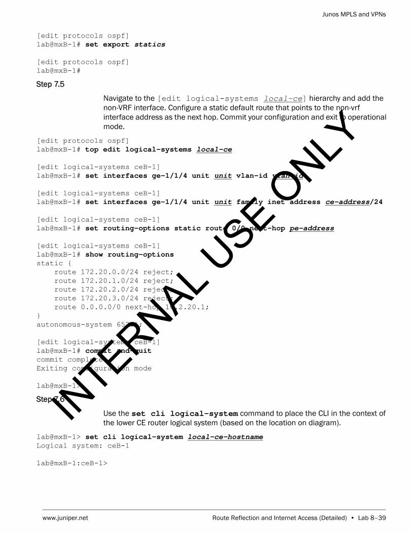
Junos MPLS and VPNs
www.juniper.net Route Reflection and Internet Access (Detailed) • Lab 8–39
[edit protocols ospf]lab@mxB-1# set export statics
[edit protocols ospf]lab@mxB-1#
Step 7.5
Navigate to the [edit logical-systems local-ce] hierarchy and add the non-VRF interface. Configure a static default route that points to the non-vrf interface address as the next hop. Commit your configuration and exit to operational mode.
[edit protocols ospf]lab@mxB-1# top edit logical-systems local-ce
[edit logical-systems ceB-1]lab@mxB-1# set interfaces ge-1/1/4 unit unit vlan-id vlan-id
[edit logical-systems ceB-1]lab@mxB-1# set interfaces ge-1/1/4 unit unit family inet address ce-address/24
[edit logical-systems ceB-1]lab@mxB-1# set routing-options static route 0/0 next-hop pe-address
[edit logical-systems ceB-1]lab@mxB-1# show routing-options static { route 172.20.0.0/24 reject; route 172.20.1.0/24 reject; route 172.20.2.0/24 reject; route 172.20.3.0/24 reject; route 0.0.0.0/0 next-hop 10.2.20.1;}autonomous-system 65201;
[edit logical-systems ceB-1]lab@mxB-1# commit and-quit commit completeExiting configuration mode
lab@mxB-1>
Step 7.6
Use the set cli logical-system command to place the CLI in the context of the lower CE router logical system (based on the location on diagram).
lab@mxB-1> set cli logical-system local-ce-hostname Logical system: ceB-1
lab@mxB-1:ceB-1>
INTERNAL U
SE ONLY

Junos MPLS and VPNs
Lab 8–40 • Route Reflection and Internet Access (Detailed) www.juniper.net
Step 7.7
Issue the ping p-router-loopback source local-ce-loopback count 5 command to verify that you can ping the loopback address of one of the core routers five times, sourced from your CE router’s loopback address. You can review Part 1 diagram that shows the core network if you do not recall the loopback addresses of the core routers.
lab@mxB-1:ceB-1> ping p-router-loopback source local-ce-loopback count 5 PING 193.168.5.6 (193.168.5.6): 56 data bytes64 bytes from 193.168.5.6: icmp_seq=0 ttl=61 time=0.801 ms64 bytes from 193.168.5.6: icmp_seq=1 ttl=61 time=0.761 ms64 bytes from 193.168.5.6: icmp_seq=2 ttl=61 time=0.750 ms64 bytes from 193.168.5.6: icmp_seq=3 ttl=61 time=0.736 ms64 bytes from 193.168.5.6: icmp_seq=4 ttl=61 time=0.716 ms
--- 193.168.5.6 ping statistics ---5 packets transmitted, 5 packets received, 0% packet lossround-trip min/avg/max/stddev = 0.716/0.753/0.801/0.028 ms
Question: Do the ping requests complete?
Answer: Yes, the pings should complete. If they do not, please review your configuration and request assistance from your instructor as needed.
Step 7.8
Issue the clear cli logical-system to return to the CLI context of the default routing instance (your PE router).
lab@mxB-1:ceB-1> clear cli logical-system Cleared default logical system
lab@mxB-1>
Step 7.9
Log out of your assigned device using the exit command.
lab@mxB-1> exit
mxB-1 (ttyu0)
login:
STOP Tell your instructor that you have completed this lab.
INTERNAL U
SE ONLY

Junos MPLS and VPNs
www.juniper.net Route Reflection and Internet Access (Detailed) • Lab 8–41
INTERNAL U
SE ONLY

Junos MPLS and VPNs
Lab 8–42 • Route Reflection and Internet Access (Detailed) www.juniper.net
INTERNAL U
SE ONLY

Junos MPLS and VPNs
www.juniper.net Route Reflection and Internet Access (Detailed) • Lab 8–43
INTERNAL U
SE ONLY

Junos MPLS and VPNs
Lab 8–44 • Route Reflection and Internet Access (Detailed) www.juniper.net
INTERNAL U
SE ONLY
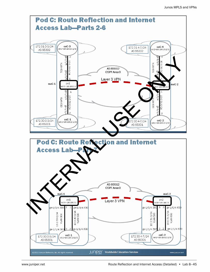
Junos MPLS and VPNs
www.juniper.net Route Reflection and Internet Access (Detailed) • Lab 8–45
INTERNAL U
SE ONLY
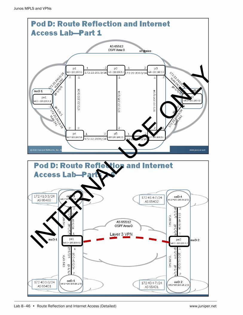
Junos MPLS and VPNs
Lab 8–46 • Route Reflection and Internet Access (Detailed) www.juniper.net
INTERNAL U
SE ONLY

Junos MPLS and VPNs
www.juniper.net Route Reflection and Internet Access (Detailed) • Lab 8–47
INTERNAL U
SE ONLY

Junos MPLS and VPNs
Lab 8–48 • Route Reflection and Internet Access (Detailed) www.juniper.net
INTERNAL U
SE ONLY

www.juniper.net GRE Tunnel Integration (Detailed) • Lab 9–1
LabGRE Tunnel Integration (Detailed)
Overview
In this lab, you will establish a point-to-point Layer 3 virtual private network (VPN) using a generic routing encapsulation (GRE) tunnel between provider edge (PE) routers. You will also configure OSPF routing between your PE and customer edge (CE) router. You will share your routes with the remote PE through the Layer 3 VPN using Multiprotocol Border Gateway Protocol (MP-BGP).
The lab is available in two formats: a high-level format that is designed to make you think through each step and a detailed format that offers step-by-step instructions complete with sample output from most commands.
By completing this lab, you will perform the following tasks:
• Load a baseline configuration for your router. This configuration includes your baseline core configuration including OSPF and BGP. The baseline also contains a logical router configuration that will act as your CE router for this lab.
• Configure a VPN routing and forwarding (VRF) table and OSPF routing between your PE router and CE router and redistribute your CE router’s static routes into OSPF.
• Configure a GRE tunnel to the remote PE router.
• Create and add a static route to inet.3.
• Redistribute the MP-BGP routes learned from the remote PE into OSPF.
• Verify connectivity and behavior using operational mode commands including ping and commands used to examine routing tables, and PE-PE BGP announcements.IN
TERNAL USE O
NLY

Junos MPLS and VPNs
Lab 9–2 • GRE Tunnel Integration (Detailed) www.juniper.net
Part 1: Creating the Baseline SP Network and Enabling PE for Layer 3 VPN Signaling
In this lab part, you will configure the baseline network for the lab. You will load a baseline configuration and then configure MP-BGP and a route-distinguisher ID.
Step 1.1
Ensure that you know to which device you are assigned. Check with your instructor if necessary.
Step 1.2
Consult the management network diagram, provided by your instructor, to determine your device’s management address.
Question: What is the management address assigned to your station?
Answer: The answer varies. The sample hostname and IP address used in the output examples in this lab are for mxB-1, which uses 10.210.15.3 as its management IP address. The actual management subnet varies between delivery environments.
Step 1.3
Access the CLI at your station using either the console, Telnet, or Secure Shell (SSH) as directed by your instructor. The following example shows simple Telnet access to mxB-1 using the Secure CRT program.
Note
The instructor will tell you the nature of your access and will provide you with the necessary details to access your assigned device.
INTERNAL U
SE ONLY

Junos MPLS and VPNs
www.juniper.net GRE Tunnel Integration (Detailed) • Lab 9–3
Step 1.4
Log in as user lab with the password supplied by your instructor. Enter configuration mode and load the reset configuration file jmv/lab9-start.config and commit.
mxB-1 (ttyp0)
login: labPassword:
--- JUNOS 12.3R2.5 built 2013-03-22 17:12:14 UTClab@mxB-1> configure Entering configuration mode
[edit]lab@mxB-1# load override jmv/lab9-start.config load complete
[edit]lab@mxB-1# commit commit complete
[edit]lab@mxB-1#
Step 1.5
Navigate to the [edit protocols] hierarchy. Issue the show command and analyze the protocols that have been preconfigured for you.
[edit]lab@mxB-1# edit protocols
[edit protocols]lab@mxB-1# show bgp { group my-int-group { type internal; local-address 193.168.2.1; neighbor 193.168.2.2; }}ospf { area 0.0.0.0 { interface ge-1/0/0.220; interface ge-1/0/1.221; interface lo0.0; }}
[edit protocols]lab@mxB-1#
INTERNAL U
SE ONLY

Junos MPLS and VPNs
Lab 9–4 • GRE Tunnel Integration (Detailed) www.juniper.net
Question: Which protocols have been preconfigured for you?
Answer: OSPF and BGP have been preconfigured.
Question: What is the name of the preconfigured BGP peer group? Which router in the network is configured as a member of the group?
Answer: The configured peer group is called my-int-group. The group is configured to establish an IBGP session with the remote PE.
Step 1.6
Exit to operational mode and verify your Open Shortest Path First (OSPF) neighbor relationships are up and operational.
[edit protocols]lab@mxB-1# exit configuration-mode Exiting configuration mode
lab@mxB-1> show ospf neighbor Address Interface State ID Pri Dead172.22.220.2 ge-1/0/0.220 Full 193.168.5.1 128 34172.22.221.2 ge-1/0/1.221 Full 193.168.5.4 128 39
Question: What is the state of your PE router’s OSPF neighbors?
Answer: After a short time, the OSPF neighbors should attain the Full state.
Step 1.7
Verify that your PE router has established an IBGP neighbor relationship with the remote PE router.
lab@mxB-1> show bgp neighborPeer: 193.168.2.2+179 AS 65512 Local: 193.168.2.1+58282 AS 65512 Type: Internal State: Established Flags: <Sync> Last State: OpenConfirm Last Event: RecvKeepAlive Last Error: None Options: <Preference LocalAddress Refresh> Local Address: 193.168.2.1 Holdtime: 90 Preference: 170
INTERNAL U
SE ONLY

Junos MPLS and VPNs
www.juniper.net GRE Tunnel Integration (Detailed) • Lab 9–5
Number of flaps: 0 Peer ID: 193.168.2.2 Local ID: 193.168.2.1 Active Holdtime: 90 Keepalive Interval: 30 Group index: 0 Peer index: 0 BFD: disabled, down NLRI for restart configured on peer: inet-unicast NLRI advertised by peer: inet-unicast NLRI for this session: inet-unicast Peer supports Refresh capability (2) Stale routes from peer are kept for: 300 Peer does not support Restarter functionality NLRI that restart is negotiated for: inet-unicast NLRI of received end-of-rib markers: inet-unicast NLRI of all end-of-rib markers sent: inet-unicast Peer supports 4 byte AS extension (peer-as 65512) Peer does not support Addpath Table inet.0 Bit: 10001 RIB State: BGP restart is complete Send state: in sync Active prefixes: 0 Received prefixes: 0 Accepted prefixes: 0 Suppressed due to damping: 0 Advertised prefixes: 0 Last traffic (seconds): Received 19 Sent 8 Checked 31 Input messages: Total 9219 Updates 4 Refreshes 0 Octets 175246 Output messages: Total 9218 Updates 2 Refreshes 0 Octets 175250 Output Queue[0]: 0
Question: Is the neighbor relationship in the established state with the remote PE router?
Answer: The remote PE router should be in an established state with your PE router. If it is not, double check the interface and BGP settings. If you need further assistance, consult with your instructor.
Question: What address family has been negotiated for the BGP session? What type of routes can be advertised between the two PE routers?
Answer: The PE routers have negotiated the advertisement of inet-unicast routes. That means that only IPv4 unicast routes can be advertised between the two neighbors.
INTERNAL U
SE ONLY

Junos MPLS and VPNs
Lab 9–6 • GRE Tunnel Integration (Detailed) www.juniper.net
Step 1.8
For an interface to support the forwarding of MPLS packets, you must enable the MPLS family on each interface. Enter configuration mode and navigate to the [edit interfaces] hierarchy and enable family mpls on both of the core-facing interfaces.
lab@mxB-1> configure Entering configuration mode
[edit]lab@mxB-1# edit interfaces
[edit interfaces]lab@mxB-1# set ge-1/0/0 unit unit family mpls
[edit interfaces]lab@mxB-1# set ge-1/0/1 unit unit family mpls
[edit interfaces]lab@mxB-1#
Step 1.9
Navigate to the [edit protocols] hierarchy and configure the MPLS protocol on the core-facing interfaces.
[edit interfaces]lab@mxB-1# top edit protocols
[edit protocols]lab@mxB-1# set mpls interface ge-1/0/0.unit
[edit protocols]lab@mxB-1# set mpls interface ge-1/0/1.unit
Step 1.10
To allow the exchange of Layer 3 VPN routes, enable the inet-vpn unicast network layer reachability information (NLRI) for your PE router’s BGP session with the remote PE router. Make sure to also enable the exchange of standard unicast IP version 4 (IPv4) routes as well.
[edit protocols]lab@mxB-1# set bgp group my-int-group family inet unicast
[edit protocols]lab@mxB-1# set bgp group my-int-group family inet-vpn unicast
Step 1.11
To allow for the automatic generation of route distinguishers, navigate to the [edit routing-options] hierarchy and specify the route-distinguisher-id using your PE router’s loopback address. Commit your configuration and exit out to operational mode.
[edit protocols]lab@mxB-1# top edit routing-options
INTERNAL U
SE ONLY

Junos MPLS and VPNs
www.juniper.net GRE Tunnel Integration (Detailed) • Lab 9–7
[edit routing-options]lab@mxB-1# set route-distinguisher-id local-pe-loopback-address
[edit routing-options]lab@mxB-1# commit and-quit commit completeExiting configuration mode
lab@mxB-1>
Step 1.12
Using the show mpls interface command, verify that MPLS is configured correctly on the core-facing interfaces.
lab@mxB-1> show mpls interface Interface State Administrative groups (x: extended)ge-1/0/0.220 Up <none>ge-1/0/1.221 Up <none>
Question: Can your core-facing interfaces now support the transmission of MPLS packets?
Answer: The outputs of the two commands show that the two interfaces can now support the forwarding of MPLS packets.
Step 1.13
Verify the state of your PE router’s BGP neighbor relationship with the remote PE router.
lab@mxB-1> show bgp neighbor remote-pe-addressPeer: 193.168.2.2+52281 AS 65512 Local: 193.168.2.1+179 AS 65512 Type: Internal State: Established Flags: <Sync> Last State: OpenConfirm Last Event: RecvKeepAlive Last Error: None Options: <Preference LocalAddress AddressFamily Rib-group Refresh> Address families configured: inet-unicast inet-vpn-unicast Local Address: 193.168.2.1 Holdtime: 90 Preference: 170 Number of flaps: 1 Last flap event: RecvNotify Error: 'Cease' Sent: 0 Recv: 1 Peer ID: 193.168.2.2 Local ID: 193.168.2.1 Active Holdtime: 90 Keepalive Interval: 30 Group index: 0 Peer index: 0 BFD: disabled, down NLRI for restart configured on peer: inet-unicast inet-vpn-unicast NLRI advertised by peer: inet-unicast inet-vpn-unicast NLRI for this session: inet-unicast inet-vpn-unicast Peer supports Refresh capability (2) Stale routes from peer are kept for: 300 Peer does not support Restarter functionality NLRI that restart is negotiated for: inet-unicast inet-vpn-unicast
INTERNAL U
SE ONLY

Junos MPLS and VPNs
Lab 9–8 • GRE Tunnel Integration (Detailed) www.juniper.net
NLRI of received end-of-rib markers: inet-unicast inet-vpn-unicast NLRI of all end-of-rib markers sent: inet-unicast inet-vpn-unicast Peer supports 4 byte AS extension (peer-as 65512) Peer does not support Addpath Table inet.0 Bit: 10000 RIB State: BGP restart is complete Send state: in sync Active prefixes: 0 Received prefixes: 0 Accepted prefixes: 0 Suppressed due to damping: 0 Advertised prefixes: 0 Table bgp.l3vpn.0 RIB State: BGP restart is complete RIB State: VPN restart is complete Send state: not advertising Active prefixes: 0 Received prefixes: 0 Accepted prefixes: 0 Suppressed due to damping: 0 Last traffic (seconds): Received 15 Sent 15 Checked 15 Input messages: Total 4 Updates 2 Refreshes 0 Octets 139 Output messages: Total 3 Updates 0 Refreshes 0 Octets 158 Output Queue[0]: 0 Output Queue[1]: 0
Question: Is the neighbor relationship in the established state with the remote PE?
Answer: The remote PE router should be in an established state with your PE router. If it is not, double check the interface and BGP settings. If you need further assistance, consult with your instructor.
Question: What NLRI type has been negotiated between your PE router and the remote PE router?
Answer: Using the show bgp neighbor command, you should see that the NLRI for this session should be inet-unicast and inet-vpn-unicast.
INTERNAL U
SE ONLY

Junos MPLS and VPNs
www.juniper.net GRE Tunnel Integration (Detailed) • Lab 9–9
Part 2: Verifying CE Router Configuration
In this lab part, you will view the configuration for CE router (logical system) that was preconfigured as part of the loaded starting configuration in Part 1 of this lab. Please refer to the diagram labeled “GRE Tunnel Integration Lab: Parts 2-8”.
Step 2.1
Use the set cli logical-system command to place the CLI in the context of the CE router logical system.
lab@mxB-1> set cli logical-system local-ce-hostname Logical system: ceB-1
lab@mxB-1:ceB-1>
Step 2.2
Issue the show configuration command to view the configuration of the CE router.
lab@mxB-1:ceB-1> show configuration interfaces { ge-1/1/4 { unit 620 { vlan-id 620; family inet { address 10.0.20.2/24; } } } lo0 { unit 1 { family inet { address 193.168.12.1/32; } } }}policy-options { policy-statement exp-policy { term 10 { from protocol static; then accept; } term 20 { from protocol direct; then accept; } }}routing-options { static { route 172.20.0.0/24 reject; route 172.20.1.0/24 reject; route 172.20.2.0/24 reject; route 172.20.3.0/24 reject;
INTERNAL U
SE ONLY

Junos MPLS and VPNs
Lab 9–10 • GRE Tunnel Integration (Detailed) www.juniper.net
} autonomous-system 65201;}
lab@mxB-1:ceB-1>
Question: What interfaces have been configured on the CE router? According to the lab diagram, do they have the appropriate IP addressing?
Answer: The CE router should have both the loopback and ge-1/1/4 interface configured with the appropriate addressing according to the lab diagram.
Question: What is configured under the routing-options hierarchy? According to the lab diagram, are these setting appropriate?
Answer: Four static routes (next hop of reject) and the CE router’s autonomous system should be configured under routing-options hierarchy. These settings are appropriate.
Question: What is configured under the policy-options hierarchy? What does this policy do?
Answer: A policy called exp-policy is configured under policy-options hierarchy. If applied as an export policy, this policy will redistribute active direct and static routes into the protocol to which it is applied. It is currently not applied to any protocol in the configuration.
Step 2.3
Use the ping utility to attempt to ping the local PE router’s ge-1/0/4 interface.
lab@mxB-1:ceB-1> ping local-pe-address count 1 PING 10.0.20.1 (10.0.20.1): 56 data bytes
--- 10.0.20.1 ping statistics ---1 packets transmitted, 0 packets received, 100% packet loss
INTERNAL U
SE ONLY

Junos MPLS and VPNs
www.juniper.net GRE Tunnel Integration (Detailed) • Lab 9–11
Question: Does your ping succeed? Why?
Answer: The pings do not succeed because the PE router’s ge-1/0/4 interface has not been configured at this point in the lab.
STOP Do not proceed until the remote team finishes Part 2.
Part 3: Configuring the PE to CE Interface
In this lab part, you will configure the PE to CE interface. You will verify reachability using the ping utility.
Step 3.1
Issue the clear cli logical-system to return to the CLI context of the default routing instance (your PE router).
lab@mxB-1:ceB-1> clear cli logical-system Cleared default logical system
lab@mxB-1>
Step 3.2
Enter into configuration mode and navigate to the [edit interfaces] hierarchy. Configure the appropriate interface properties foe the PE router’s ge-1/0/4 interface as found on the network diagram. Commit your change and exit to operational mode to verify reachability to the CE interface.
lab@mxB-1> configure Entering configuration mode
[edit]lab@mxB-1# edit interfaces
[edit interfaces]lab@mxB-1# set ge-1/0/4 vlan-tagging unit unit vlan-id vlan-id family inet address address/24
[edit interfaces]lab@mxB-1# commit and-quit commit completeExiting configuration mode
lab@mxB-1>
INTERNAL U
SE ONLY

Junos MPLS and VPNs
Lab 9–12 • GRE Tunnel Integration (Detailed) www.juniper.net
Step 3.3
Verify connectivity to the local CE device using the ping utility with a count value of 3.
lab@mxB-1> ping local-ce-address count 3 PING 10.0.20.2 (10.0.20.2): 56 data bytes64 bytes from 10.0.20.2: icmp_seq=0 ttl=64 time=2.024 ms64 bytes from 10.0.20.2: icmp_seq=1 ttl=64 time=0.591 ms64 bytes from 10.0.20.2: icmp_seq=2 ttl=64 time=0.552 ms
--- 10.0.20.2 ping statistics ---3 packets transmitted, 3 packets received, 0% packet lossround-trip min/avg/max/stddev = 0.552/1.056/2.024/0.685 ms
Question: Does your ping complete?
Answer: Yes, your ping should complete. If they do not, please review your configuration and request assistance from your instructor, if needed.
Part 4: Configuring a Layer 3 VPN Instance
In this lab part, you will configure a Layer 3 VPN instance. You will assign a unique route target to the VPN. You will include your CE-facing interface within this instance. In this lab, you will be using the vrf-target option because of its simplicity. Please note that vrf-import and vrf-export policies would work also.
Step 4.1
Enter into configuration mode and navigate to the [edit routing-instances] hierarchy. Create a new VRF instance named vpn-pod. For example, if you are configuring mxB-1, your VRF instance would be named vpn-B.
lab@mxB-1> configure Entering configuration mode
[edit]lab@mxB-1# edit routing-instances
[edit routing-instances]lab@mxB-1# set vpn-pod instance-type vrf
[edit routing-instances]lab@mxB-1#
Step 4.2
Navigate to the [edit routing-instances vpn-pod] hierarchy. Configure your route target. As mentioned earlier, you will be using the vrf-target option. Use the table below to determine the target community for your router.
INTERNAL U
SE ONLY

Junos MPLS and VPNs
www.juniper.net GRE Tunnel Integration (Detailed) • Lab 9–13
[edit routing-instances]lab@mxB-1# edit vpn-pod
[edit routing-instances vpn-B]lab@mxB-1# set vrf-target target-community
[edit routing-instances vpn-B]lab@mxB-1#
Step 4.3
Include the CE-facing interface in your VRF instance.
[edit routing-instances vpn-B]lab@mxB-1# set interface ge-1/0/4.unit
Step 4.4
Review your recent configuration changes. When you are satisfied with these changes, commit your configuration and exit to operational mode.
[edit routing-instances vpn-B]lab@mxB-1# show instance-type vrf;interface ge-1/0/4.620;vrf-target target:65512:2;
[edit routing-instances vpn-B]lab@mxB-1# commit and-quit commit completeExiting configuration mode
lab@mxB-1>
Step 4.5
Verify that your VRF routing table has been created and it contains the local and direct routes for your CE-facing interface. You can accomplish this task by issuing the show route table vpn-pod.inet.0 command.
lab@mxB-1> show route table vpn-pod.inet.0
vpn-B.inet.0: 8 destinations, 8 routes (2 active, 0 holddown, 6 hidden)+ = Active Route, - = Last Active, * = Both
10.0.20.0/24 *[Direct/0] 00:00:31 > via ge-1/0/4.620
Pod Target Community
A target:65512:1
B target:65512:2
C target:65512:3
D target:65512:4
INTERNAL U
SE ONLY

Junos MPLS and VPNs
Lab 9–14 • GRE Tunnel Integration (Detailed) www.juniper.net
10.0.20.1/32 *[Local/0] 00:00:31 Local via ge-1/0/4.620
Question: Do you see your local and direct routes?
Answer: You should see a local and direct route for the ge-1/0/4 interface. If you do not see these routes, please review your configuration and request assistance from your instructor, if needed.
Part 5: Configuring OSPF Routing Between the PE and CE Routers
In this lab part, you will configure OSPF routing between your PE and CE routers. These routes will be passed through the MP-BGP session to the remote PE router. You will verify that these routes are shared with the remote PE device and you will also need to verify that you are receiving the routes from the remote PE router.
Step 5.1
Use the set cli logical-system command to place the CLI in the context of the CE router logical system.
lab@mxB-1> set cli logical-system local-ce-hostname Logical system: ceB-1
lab@mxB-1:ceB-1>
Step 5.2
Enter into configuration mode and navigate to the [edit policy-options] hierarchy. Create a policy named statics that will be used to redistribute your CE router’s static routes into OSPF.
lab@mxB-1:ceB-1> configure Entering configuration mode
[edit]lab@mxB-1:ceB-1# edit policy-options
[edit policy-options]lab@mxB-1:ceB-1# set policy-statement statics term 10 from protocol static
[edit policy-options]lab@mxB-1:ceB-1# set policy-statement statics term 10 then accept
[edit policy-options]lab@mxB-1:ceB-1#
Step 5.3
Navigate to the [edit] hierarchy. Configure your CE router’s loopback and Ethernet interfaces as OSPF area 0.0.0.0 interfaces.
INTERNAL U
SE ONLY

Junos MPLS and VPNs
www.juniper.net GRE Tunnel Integration (Detailed) • Lab 9–15
[edit policy-options]lab@mxB-1:ceB-1# top
[edit]lab@mxB-1:ceB-1# set protocols ospf area 0 interface lo0.1
[edit]lab@mxB-1:ceB-1# set protocols ospf area 0 interface ge-1/1/4.unit
[edit]lab@mxB-1:ceB-1#
Step 5.4
Apply the statics policy as an export policy to your CE router’s OSPF instance. Commit your configuration and exit to operational mode.
[edit]lab@mxB-1:ceB-1# set protocols ospf export statics
[edit]lab@mxB-1:ceB-1# commit and-quit commit completeExiting configuration mode
lab@mxB-1:ceB-1>
Step 5.5
Issue the clear cli logical-system to return to the CLI context of the default routing instance (your PE router).
lab@mxB-1:ceB-1> clear cli logical-system Cleared default logical system
lab@mxB-1>
Step 5.6
Enter configuration and navigate to the [edit routing-instances vpn-pod] hierarchy. Configure your PE router’s VRF interface in OSPF area 0.0.0.0 interface. Commit your configuration and exit to operational mode.
lab@mxB-1> configure Entering configuration mode
[edit]lab@mxB-1# edit routing-instances vpn-pod
[edit routing-instances vpn-B]lab@mxB-1# set protocols ospf area 0 interface ge-1/0/4.unit
[edit routing-instances vpn-B]lab@mxB-1# commit and-quit commit completeExiting configuration mode
lab@mxB-1>
INTERNAL U
SE ONLY

Junos MPLS and VPNs
Lab 9–16 • GRE Tunnel Integration (Detailed) www.juniper.net
Step 5.7
Verify that the CE router and PE router have established an OSPF adjacency with each other.
lab@mxB-1> show ospf neighbor instance vpn-pod Address Interface State ID Pri Dead10.0.20.2 ge-1/0/4.620 Full 193.168.12.1 128 34
Question: Has the CE router established an OSPF adjacency with the local PE router?
Answer: The CE router should have established an adjacency with the local PE router. If you do not see that the neighbor relationship is in a Full state, please review your configuration and request assistance from your instructor, if needed.
Step 5.8
Verify that the static routes that are being redistributed by the CE router can be found in the VRF table of the PE router.
lab@mxB-1> show route table vpn-pod
vpn-B.inet.0: 14 destinations, 14 routes (8 active, 0 holddown, 6 hidden)+ = Active Route, - = Last Active, * = Both
10.0.20.0/24 *[Direct/0] 00:14:29 > via ge-1/0/4.62010.0.20.1/32 *[Local/0] 00:14:29 Local via ge-1/0/4.620172.20.0.0/24 *[OSPF/150] 00:02:28, metric 0, tag 0 > to 10.0.20.2 via ge-1/0/4.620172.20.1.0/24 *[OSPF/150] 00:02:28, metric 0, tag 0 > to 10.0.20.2 via ge-1/0/4.620172.20.2.0/24 *[OSPF/150] 00:02:28, metric 0, tag 0 > to 10.0.20.2 via ge-1/0/4.620172.20.3.0/24 *[OSPF/150] 00:02:28, metric 0, tag 0 > to 10.0.20.2 via ge-1/0/4.620193.168.12.1/32 *[OSPF/10] 00:02:28, metric 1 > to 10.0.20.2 via ge-1/0/4.620224.0.0.5/32 *[OSPF/10] 00:02:39, metric 1 MultiRecv
INTERNAL U
SE ONLY

Junos MPLS and VPNs
www.juniper.net GRE Tunnel Integration (Detailed) • Lab 9–17
Question: Are the static routes from the local CE router being received by your PE router as OSPF routes?
Answer: The PE router should have the received the local CE router’s static routes in the VRF table as OSPF routes. If you do not see these routes, please review your policy configuration on the CE router and request assistance from your instructor, if needed.
Step 5.9
Verify that you are advertising your OSPF routes to the remote PE router as BGP routes.
lab@mxB-1> show route advertising-protocol bgp remote-pe-loopback-address
vpn-B.inet.0: 14 destinations, 14 routes (8 active, 0 holddown, 6 hidden) Prefix Nexthop MED Lclpref AS path* 10.0.20.0/24 Self 100 I* 172.20.0.0/24 Self 0 100 I* 172.20.1.0/24 Self 0 100 I* 172.20.2.0/24 Self 0 100 I* 172.20.3.0/24 Self 0 100 I* 193.168.12.1/32 Self 1 100 I
Question: What routes are being advertised to the remote PE router?
Answer: You should see the PE-CE network, the four CE static routes, and the loopback address for the CE device. If you do not see these routes, please review your configuration and request assistance from your instructor, if needed.
Step 5.10
Verify that you are receiving routes from the remote PE router.
lab@mxB-1> show route receive-protocol bgp remote-pe-loopback-address
inet.0: 39 destinations, 39 routes (39 active, 0 holddown, 0 hidden)
vpn-B.inet.0: 14 destinations, 14 routes (8 active, 0 holddown, 6 hidden)
INTERNAL U
SE ONLY

Junos MPLS and VPNs
Lab 9–18 • GRE Tunnel Integration (Detailed) www.juniper.net
ceB-1.inet.0: 8 destinations, 8 routes (8 active, 0 holddown, 0 hidden)
mpls.0: 4 destinations, 4 routes (4 active, 0 holddown, 0 hidden)
bgp.l3vpn.0: 6 destinations, 6 routes (0 active, 0 holddown, 6 hidden)
Question: What routes are you receiving from the remote PE router?
Answer: You should notice that no BGP routes are being stored in the VRF table.
Question: Why are no BGP routes being stored in the VRF table?
Answer: The routes are hidden due to a missing route to the remote PE router’s loopback in inet.3.
Step 5.11
Determine whether any hidden routes are being received from the remote PE router.
lab@mxB-1> show route hidden
inet.0: 33 destinations, 33 routes (33 active, 0 holddown, 0 hidden)
vpn-B.inet.0: 14 destinations, 14 routes (8 active, 0 holddown, 6 hidden)+ = Active Route, - = Last Active, * = Both
10.0.21.0/24 [BGP/170] 00:17:39, localpref 100, from 193.168.2.2 AS path: I, validation-state: unverified Unusable172.10.4.0/24 [BGP/170] 00:17:39, MED 0, localpref 100, from 193.168.2.2 AS path: I, validation-state: unverified Unusable172.10.5.0/24 [BGP/170] 00:17:39, MED 0, localpref 100, from 193.168.2.2 AS path: I, validation-state: unverified Unusable172.10.6.0/24 [BGP/170] 00:17:39, MED 0, localpref 100, from 193.168.2.2 AS path: I, validation-state: unverified Unusable172.10.7.0/24 [BGP/170] 00:17:39, MED 0, localpref 100, from 193.168.2.2 AS path: I, validation-state: unverified Unusable193.168.12.2/32 [BGP/170] 00:17:39, MED 1, localpref 100, from 193.168.2.2 AS path: I, validation-state: unverified Unusable
INTERNAL U
SE ONLY

Junos MPLS and VPNs
www.juniper.net GRE Tunnel Integration (Detailed) • Lab 9–19
mpls.0: 5 destinations, 5 routes (5 active, 0 holddown, 0 hidden)
bgp.l3vpn.0: 6 destinations, 6 routes (0 active, 0 holddown, 6 hidden)+ = Active Route, - = Last Active, * = Both
193.168.2.2:11:10.0.21.0/24 [BGP/170] 00:17:39, localpref 100, from 193.168.2.2 AS path: I, validation-state: unverified Unusable193.168.2.2:11:172.10.4.0/24 [BGP/170] 00:17:39, MED 0, localpref 100, from 193.168.2.2 AS path: I, validation-state: unverified Unusable193.168.2.2:11:172.10.5.0/24 [BGP/170] 00:17:39, MED 0, localpref 100, from 193.168.2.2 AS path: I, validation-state: unverified Unusable193.168.2.2:11:172.10.6.0/24 [BGP/170] 00:17:39, MED 0, localpref 100, from 193.168.2.2 AS path: I, validation-state: unverified Unusable193.168.2.2:11:172.10.7.0/24 [BGP/170] 00:17:39, MED 0, localpref 100, from 193.168.2.2 AS path: I, validation-state: unverified Unusable193.168.2.2:11:193.168.12.2/32 [BGP/170] 00:17:39, MED 1, localpref 100, from 193.168.2.2 AS path: I, validation-state: unverified Unusable
Question: Are any hidden routes being received from the remote PE router? Why are the routes hidden?
Answer: The routes are hidden because no routes are in inet.3. The next hop is listed as unusable. There is a requirement that a route to the remote PE router’s loopback exists in inet.3. Remember that we have not yet configured an MPLS LSP which would install the necessary route.
Part 6: Establishing a GRE Tunnel Between PE Routers
In this lab part, you will configure a GRE tunnel between the PE routers.
Step 6.1
Enter configuration mode and navigate to the [edit chassis] hierarchy. Enable 1 Gbps tunnel service on FPC 1/PIC 0.
INTERNAL U
SE ONLY

Junos MPLS and VPNs
Lab 9–20 • GRE Tunnel Integration (Detailed) www.juniper.net
lab@mxB-1> configure Entering configuration mode
[edit]lab@mxB-1# edit chassis
[edit chassis]lab@mxB-1# set fpc 1 pic 0 tunnel-services bandwidth 1g
[edit chassis]lab@mxB-1#
Step 6.2
Navigate to the [edit interfaces] hierarchy and configure a tunnel interface named gr-1/0/10.0. The interface should source packets from the local PE router’s loopback address. The interface should be configured to send packets destined to the remote PE router’s loopback address. Finally, enable forwarding of MPLS and IPv4 traffic on the tunnel interface. Commit your configuration and exit to operational mode.
[edit chassis]lab@mxB-1# top edit interfaces
[edit interfaces]lab@mxB-1# set gr-1/0/10 unit 0 tunnel source local-pe-loopback-address
[edit interfaces]lab@mxB-1# set gr-1/0/10 unit 0 tunnel destination remote-pe-loopback-address
[edit interfaces]lab@mxB-1# set gr-1/0/10 unit 0 family inet
[edit interfaces]lab@mxB-1# set gr-1/0/10 unit 0 family mpls
[edit interfaces]lab@mxB-1# commit and-quit commit completeExiting configuration mode
lab@mxB-1>
Step 6.3
Verify that the GRE interface is up and functional.
lab@mxB-1> show interfaces gr-1/0/10 terse Interface Admin Link Proto Local Remotegr-1/0/10 up up gr-1/0/10.0 up up inet mpls
INTERNAL U
SE ONLY

Junos MPLS and VPNs
www.juniper.net GRE Tunnel Integration (Detailed) • Lab 9–21
Question: Is the gr-1/0/10 interface in the up state?
Answer: The tunnel interface should be in the up state. If not, check your configuration and ask your instructor for help, if needed.
Part 7: Creating and Adding a Static Route to inet.3
In this lab part, you will configure a static route to the loopback of the remote PE such that it is placed in the inet.3 routing table.
Step 7.1
Enter configuration mode and navigate to the [edit routing-options] hierarchy. Create a static route to the loopback address of the remote PE router that will exist only in inet.3 and has a next hop of the gr-1/0/10.0 interface. Commit your configuration and exit to operational mode.
lab@mxB-1> configure Entering configuration mode
[edit]lab@mxB-1# edit routing-options
[edit routing-options]lab@mxB-1# set rib inet.3 static route remote-pe-loopback-address/32 next-hop gr-1/0/10.0
[edit routing-options]lab@mxB-1# commit and-quit commit completeExiting configuration mode
lab@mxB-1>
Step 7.2
Verify that the new static route exists in inet.3 and only inet.3.
lab@mxB-1> show route remote-pe-loopback-address
inet.0: 33 destinations, 33 routes (33 active, 0 holddown, 0 hidden)+ = Active Route, - = Last Active, * = Both
193.168.2.2/32 *[OSPF/10] 6d 07:14:37, metric 4 > to 172.22.221.2 via ge-1/0/1.221 to 172.22.220.2 via ge-1/0/0.220
inet.3: 1 destinations, 1 routes (1 active, 0 holddown, 0 hidden)+ = Active Route, - = Last Active, * = Both
INTERNAL U
SE ONLY

Junos MPLS and VPNs
Lab 9–22 • GRE Tunnel Integration (Detailed) www.juniper.net
193.168.2.2/32 *[Static/5] 00:00:28 > via gr-1/0/10.0
Question: In which routing table has the static route been placed?
Answer: The route should only be in the inet.3 table. If not, check your configuration and ask your instructor for help if needed.
Step 7.3
Review the routes that are installed in your VRF table.
lab@mxB-1> show route table vpn-pod.inet.0
vpn-B.inet.0: 14 destinations, 14 routes (14 active, 0 holddown, 0 hidden)+ = Active Route, - = Last Active, * = Both
10.0.20.0/24 *[Direct/0] 00:28:39 > via ge-1/0/4.62010.0.20.1/32 *[Local/0] 00:28:39 Local via ge-1/0/4.62010.0.21.0/24 *[BGP/170] 00:05:10, localpref 100, from 193.168.2.2 AS path: I, validation-state: unverified > via gr-1/0/10.0, Push 300064172.20.0.0/24 *[OSPF/150] 00:16:38, metric 0, tag 0 > to 10.0.20.2 via ge-1/0/4.620172.20.1.0/24 *[OSPF/150] 00:16:38, metric 0, tag 0 > to 10.0.20.2 via ge-1/0/4.620172.20.2.0/24 *[OSPF/150] 00:16:38, metric 0, tag 0 > to 10.0.20.2 via ge-1/0/4.620172.20.3.0/24 *[OSPF/150] 00:16:38, metric 0, tag 0 > to 10.0.20.2 via ge-1/0/4.620172.20.4.0/24 *[BGP/170] 00:00:14, MED 0, localpref 100, from 193.168.2.2 AS path: I, validation-state: unverified > via gr-1/0/10.0, Push 300064172.20.5.0/24 *[BGP/170] 00:00:14, MED 0, localpref 100, from 193.168.2.2 AS path: I, validation-state: unverified > via gr-1/0/10.0, Push 300064172.20.6.0/24 *[BGP/170] 00:00:14, MED 0, localpref 100, from 193.168.2.2 AS path: I, validation-state: unverified > via gr-1/0/10.0, Push 300064172.20.7.0/24 *[BGP/170] 00:00:14, MED 0, localpref 100, from 193.168.2.2 AS path: I, validation-state: unverified > via gr-1/0/10.0, Push 300064193.168.12.1/32 *[OSPF/10] 00:16:38, metric 1 > to 10.0.20.2 via ge-1/0/4.620193.168.12.2/32 *[BGP/170] 00:05:10, MED 1, localpref 100, from 193.168.2.2 AS path: I, validation-state: unverified
INTERNAL U
SE ONLY

Junos MPLS and VPNs
www.juniper.net GRE Tunnel Integration (Detailed) • Lab 9–23
> via gr-1/0/10.0, Push 300064224.0.0.5/32 *[OSPF/10] 00:16:49, metric 1 MultiRecv
Question: Do you see all the remote PE routes?
Answer: Yes, you should see all the remote PE routes.
Question: What is the next hop for the routes that have been received from the remote PE router?
Answer: The next hop should be the gr-1/0/10.0 interface.
Step 7.4
Use the set cli logical-system command to place the CLI in the context of the CE router logical system.
lab@mxB-1> set cli logical-system local-ce-hostname Logical system: ceB-1
lab@mxB-1:ceB-1>
Step 7.5
Verify that you have connectivity from CE router to CE router through the Layer 3 VPN by using the ping utility. You will ping the remote CE router’s loopback address while sourcing the packets from your local CE router’s loopback address. You will send five packets for this test. This task can be accomplished using the following command: ping remote-ce-loopback source local-ce-loopback count 5 .
lab@mxB-1:ceB-1> ping remote-ce-loopback source local-ce-loopback count 5 PING 193.168.12.2 (192.168.12.2): 56 data bytesping: sendto: No route to hostping: sendto: No route to hostping: sendto: No route to hostping: sendto: No route to hostping: sendto: No route to host^C--- 193.168.12.2 ping statistics ---5 packets transmitted, 0 packets received, 100% packet loss
INTERNAL U
SE ONLY

Junos MPLS and VPNs
Lab 9–24 • GRE Tunnel Integration (Detailed) www.juniper.net
Question: Do all your ping packets complete? Can you think of a reason why they would not complete?
Answer: No, they should not succeed. Go through the next few steps of the lab to determine why they do not succeed.
Step 7.6
Review the routes that are installed in the CE router’s routing table.
lab@mxB-1:ceB-1> show route
inet.0: 8 destinations, 8 routes (8 active, 0 holddown, 0 hidden)+ = Active Route, - = Last Active, * = Both
10.0.20.0/24 *[Direct/0] 6d 07:22:37 > via ge-1/1/4.62010.0.20.2/32 *[Local/0] 6d 07:22:37 Local via ge-1/1/4.620172.20.0.0/24 *[Static/5] 6d 07:22:37 Reject172.20.1.0/24 *[Static/5] 6d 07:22:37 Reject172.20.2.0/24 *[Static/5] 6d 07:22:37 Reject172.20.3.0/24 *[Static/5] 6d 07:22:37 Reject193.168.12.1/32 *[Direct/0] 6d 07:22:37 > via lo0.1224.0.0.5/32 *[OSPF/10] 00:23:54, metric 1 MultiRecv
Question: Do you see all the remote routes?
Answer: No, the remote routes should not exist in the CE router’s routing table.
Step 7.7
Review the LSAs that currently exist in the CE router’s link state database.
lab@mxB-1:ceB-1> show ospf database
Area 0.0.0.0 Type ID Adv Rtr Seq Age Opt Cksum Len Router 10.0.20.1 10.0.20.1 0x80000002 1262 0x22 0x278c 36Router *193.168.12.1 193.168.12.1 0x80000004 1261 0x22 0xde98 48Network *10.0.20.2 193.168.12.1 0x80000001 1266 0x22 0x46c5 32
INTERNAL U
SE ONLY

Junos MPLS and VPNs
www.juniper.net GRE Tunnel Integration (Detailed) • Lab 9–25
OSPF AS SCOPE link state database Type ID Adv Rtr Seq Age Opt Cksum Len Extern *172.20.0.0 193.168.12.1 0x80000002 712 0x22 0xd99f 36Extern *172.20.1.0 193.168.12.1 0x80000002 222 0x22 0xcea9 36Extern *172.20.2.0 193.168.12.1 0x80000001 1501 0x22 0xc5b2 36Extern *172.20.3.0 193.168.12.1 0x80000001 1501 0x22 0xbabc 36
Question: Why do you think the remote networks are not present in your CE router’s link state database?
Answer: This answer will vary by student.
Question: How are the routes learned from the remote PE routers? How are these routes characterized in your PE router’s VRF table? What protocol is running on the PE/CE link?
Answer: The routes from the remote PE router are learned through BGP. The routes appear as BGP routes in the PE router’s routing table. OSPF is running on the PE/CE link.
Question: Will the default OSPF export policy advertise routes learned by BGP?
Answer: BGP routes are not redistributed into OSPF by default. You must create and apply a policy to the VRF instance of OSPF to cause the redistribution of the BGP routes into OSPF.
STOP Do not proceed until the remote team finishes Part 7.
Part 8: Redistributing BGP Routes into OSPF
In this lab part, you will configure a routing policy that will take the BGP routes learned from the remote PE router and redistribute them into OSPF.
INTERNAL U
SE ONLY

Junos MPLS and VPNs
Lab 9–26 • GRE Tunnel Integration (Detailed) www.juniper.net
Step 8.1
Issue the clear cli logical-system to return to the CLI context of the default routing instance (your PE router).
lab@mxB-1:ceB-1> clear cli logical-system Cleared default logical system
lab@mxB-1>
Step 8.2
Enter configuration mode and navigate to the [edit policy-options] hierarchy. Create a policy named bgp-to-ospf that will be used to redistribute BGP routes into OSPF.
lab@mxB-1> configure Entering configuration mode
[edit]lab@mxB-1# edit policy-options
[edit policy-options]lab@mxB-1# set policy-statement bgp-to-ospf term 10 from protocol bgp
[edit policy-options]lab@mxB-1# set policy-statement bgp-to-ospf term 10 then accept
[edit policy-options]lab@mxB-1#
Step 8.3
Navigate to [edit routing-instances vpn-pod] and apply the bgp-to-ospf policy as an export policy to the VRF’s OSPF instance. Commit your configuration and exit to operational mode.
[edit policy-options]lab@mxB-1# top edit routing-instances vpn-pod
[edit routing-instances vpn-B]lab@mxB-1# set protocols ospf export bgp-to-ospf
[edit routing-instances vpn-B]lab@mxB-1# commit and-quit commit completeExiting configuration mode
lab@mxB-1>
Step 8.4
Use the set cli logical-system command to place the CLI in the context of the CE router logical system.
lab@mxB-1> set cli logical-system local-ce-hostname Logical system: ceB-1
lab@mxB-1:ceB-1>
INTERNAL U
SE ONLY
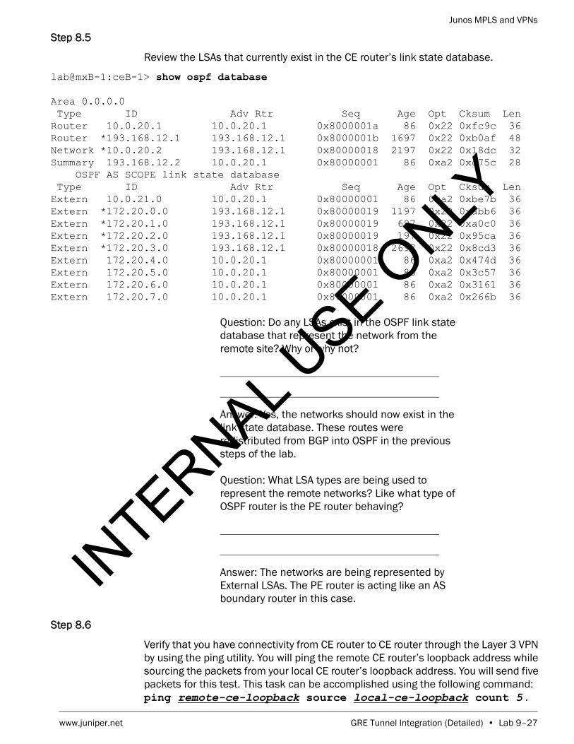
Junos MPLS and VPNs
www.juniper.net GRE Tunnel Integration (Detailed) • Lab 9–27
Step 8.5
Review the LSAs that currently exist in the CE router’s link state database.
lab@mxB-1:ceB-1> show ospf database
Area 0.0.0.0 Type ID Adv Rtr Seq Age Opt Cksum Len Router 10.0.20.1 10.0.20.1 0x8000001a 86 0x22 0xfc9c 36Router *193.168.12.1 193.168.12.1 0x8000001b 1697 0x22 0xb0af 48Network *10.0.20.2 193.168.12.1 0x80000018 2197 0x22 0x18dc 32Summary 193.168.12.2 10.0.20.1 0x80000001 86 0xa2 0xc75c 28 OSPF AS SCOPE link state database Type ID Adv Rtr Seq Age Opt Cksum Len Extern 10.0.21.0 10.0.20.1 0x80000001 86 0xa2 0xbe7b 36Extern *172.20.0.0 193.168.12.1 0x80000019 1197 0x22 0xabb6 36Extern *172.20.1.0 193.168.12.1 0x80000019 697 0x22 0xa0c0 36Extern *172.20.2.0 193.168.12.1 0x80000019 197 0x22 0x95ca 36Extern *172.20.3.0 193.168.12.1 0x80000018 2697 0x22 0x8cd3 36Extern 172.20.4.0 10.0.20.1 0x80000001 86 0xa2 0x474d 36Extern 172.20.5.0 10.0.20.1 0x80000001 86 0xa2 0x3c57 36Extern 172.20.6.0 10.0.20.1 0x80000001 86 0xa2 0x3161 36Extern 172.20.7.0 10.0.20.1 0x80000001 86 0xa2 0x266b 36
Question: Do any LSAs exist in the OSPF link state database that represent the network from the remote site? Why or why not?
Answer: Yes, the networks should now exist in the link state database. These routes were redistributed from BGP into OSPF in the previous steps of the lab.
Question: What LSA types are being used to represent the remote networks? Like what type of OSPF router is the PE router behaving?
Answer: The networks are being represented by External LSAs. The PE router is acting like an AS boundary router in this case.
Step 8.6
Verify that you have connectivity from CE router to CE router through the Layer 3 VPN by using the ping utility. You will ping the remote CE router’s loopback address while sourcing the packets from your local CE router’s loopback address. You will send five packets for this test. This task can be accomplished using the following command: ping remote-ce-loopback source local-ce-loopback count 5 .
INTERNAL U
SE ONLY
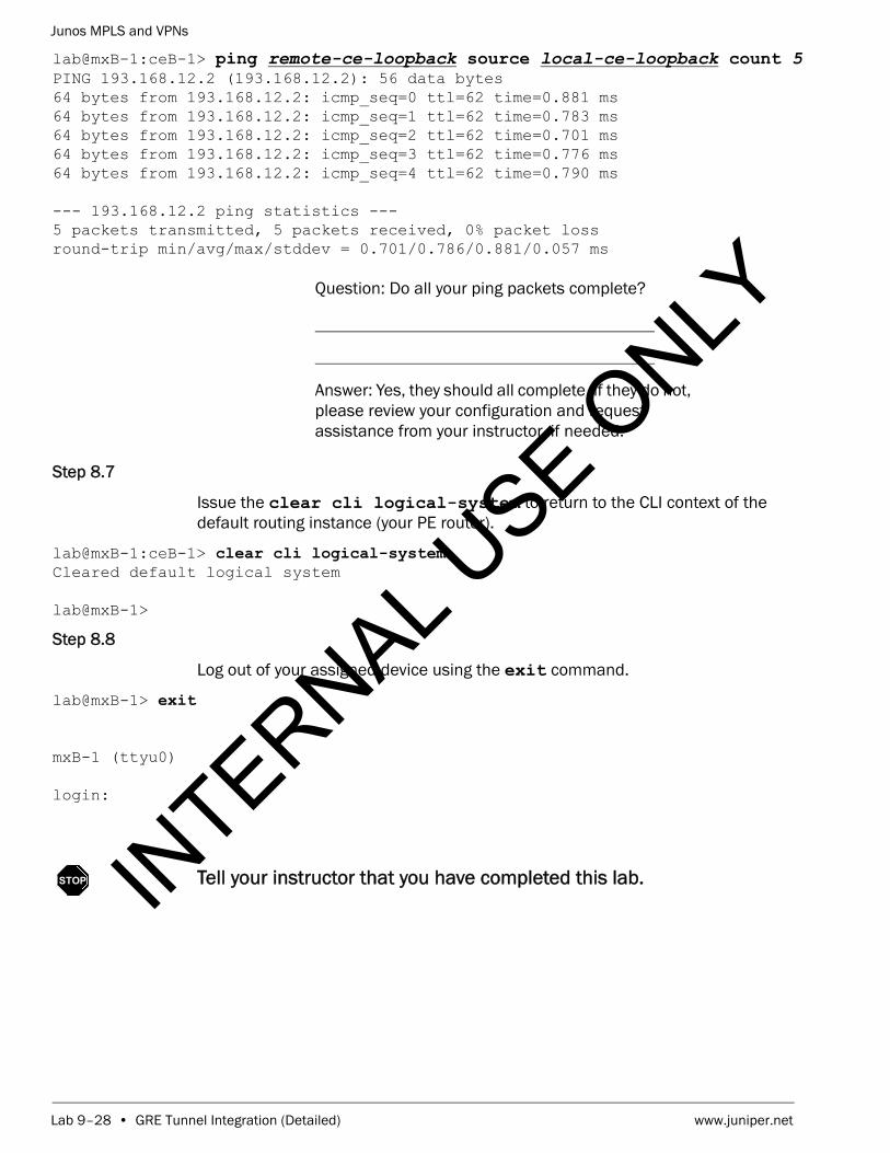
Junos MPLS and VPNs
Lab 9–28 • GRE Tunnel Integration (Detailed) www.juniper.net
lab@mxB-1:ceB-1> ping remote-ce-loopback source local-ce-loopback count 5 PING 193.168.12.2 (193.168.12.2): 56 data bytes64 bytes from 193.168.12.2: icmp_seq=0 ttl=62 time=0.881 ms64 bytes from 193.168.12.2: icmp_seq=1 ttl=62 time=0.783 ms64 bytes from 193.168.12.2: icmp_seq=2 ttl=62 time=0.701 ms64 bytes from 193.168.12.2: icmp_seq=3 ttl=62 time=0.776 ms64 bytes from 193.168.12.2: icmp_seq=4 ttl=62 time=0.790 ms
--- 193.168.12.2 ping statistics ---5 packets transmitted, 5 packets received, 0% packet lossround-trip min/avg/max/stddev = 0.701/0.786/0.881/0.057 ms
Question: Do all your ping packets complete?
Answer: Yes, they should all complete. if they do not, please review your configuration and request assistance from your instructor, if needed.
Step 8.7
Issue the clear cli logical-system to return to the CLI context of the default routing instance (your PE router).
lab@mxB-1:ceB-1> clear cli logical-system Cleared default logical system
lab@mxB-1>
Step 8.8
Log out of your assigned device using the exit command.
lab@mxB-1> exit
mxB-1 (ttyu0)
login:
STOP Tell your instructor that you have completed this lab.IN
TERNAL USE O
NLY

Junos MPLS and VPNs
www.juniper.net GRE Tunnel Integration (Detailed) • Lab 9–29
INTERNAL U
SE ONLY

Junos MPLS and VPNs
Lab 9–32 • GRE Tunnel Integration (Detailed) www.juniper.net
INTERNAL U
SE ONLY

Junos MPLS and VPNs
www.juniper.net GRE Tunnel Integration (Detailed) • Lab 9–33
INTERNAL U
SE ONLY

Junos MPLS and VPNs
Lab 9–34 • GRE Tunnel Integration (Detailed) www.juniper.net
INTERNAL U
SE ONLY


