JMol Training Guide
41
1ZAA.pdb 1ZAA.pdb version 1.0
Transcript of JMol Training Guide
7/25/2019 JMol Training Guide
http://slidepdf.com/reader/full/jmol-training-guide 1/40
1ZAA.pdb
1ZAA.pdb
version 1.0
7/25/2019 JMol Training Guide
http://slidepdf.com/reader/full/jmol-training-guide 2/40
Contents
Acknowledgements
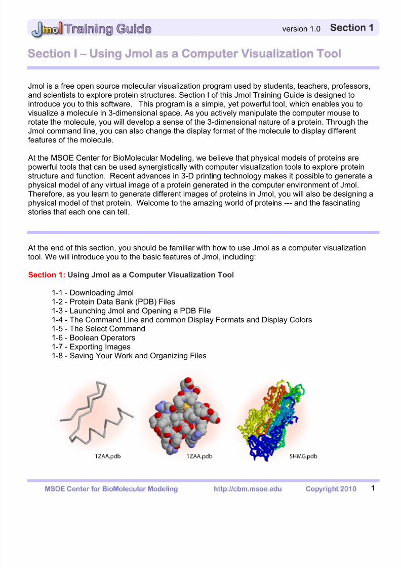
Section 1: Using Jmol as a Computer Visualization Tool
1-1 - Downloading Jmol1-2 - Protein Data Bank (PDB) Files1-3 - Launching Jmol and Opening a PDB File1-4 - The Command Line and common Display Formats and Display Colors1-5 - The Select Command
1-6 - Boolean Operators1-7 - Exporting Images1-8 - Saving Your Work and Organizing Files
Section 2: Understanding the Protein Data Bank
2-1 - Using the RCSD Protein Data Bank2-2 - Searching the RCSD Protein Data Bank
2-3 - Inside a PDB file2-4 - Referencing the RCSD Protein Data Bank
Section 3: Designing Models for Rapid Prototyping
3-1 - What is 3D Printing?3-2 - Selecting Appropriate Display Formats and Colors3-3 - Adding and Removing Hydrogen Bonds and Disulfide Bonds3-4 - Adding and Removing Support Struts
3-5 - Coloring Hydrogen Bonds, SS Bonds, and Struts3-6 - Adding Sidechains with a “Clean Backbone"3-7 - Additional Miscellaneous Jmol Commands

7/25/2019 JMol Training Guide
http://slidepdf.com/reader/full/jmol-training-guide 3/40
cknowledgments
The MSOE Center for BioMolecular Modeling would like to thank the countless teachers who haveattended workshops over the years for their input in creating this document. Their inspiration and
requests for something that would assist them in working with molecular visualization and Jmol hasallowed the CBM to put this Training Guide together.
This publication was made possible by a Science Education Partnership Award from the NationalCenter for Research Resources (NCRR), a component of the National Institutes of Health (NIH).(Grant # 1 R25 RR022749-01)
7/25/2019 JMol Training Guide
http://slidepdf.com/reader/full/jmol-training-guide 4/40

7/25/2019 JMol Training Guide
http://slidepdf.com/reader/full/jmol-training-guide 5/40
2
version 1.0
1-1 - Downloading Jmol
About Jmol – Jmol runs on a Java platform and therefore functions equally well in a PC orMac environment. Because Jmol is freeware and an open source program, it can be obtained
from many locations. For total functionality in designing a structure to be built on a 3-Dprinter, you must use the version 12.0.14 that is available on our website.
Downloading Jmol - We suggest that you download jmol directly from the Center forBioMolecular Modeling's website to ensure you are using the correct version for creatingphysical models.
o http://cbm.msoe.edu/stupro/smart/resources.html
Unzipping Jmol - The program Jmol should download as one zipped folder that will need to
be unzipped. Most computers running Microsoft Windows will automatically do this using theprogram WinZip. If your computer does not have WinZip, you may download the freeunzipping software CAM UnZip, available at:
o http://www.camunzip.com/
Unzipping for Mac - If you are using a Mac that does not have an unzipping program, youmay download the free unzipping software MacZip, available at:
o http://download.cnet.com/MacZip/3000-2250_4-10025248.html
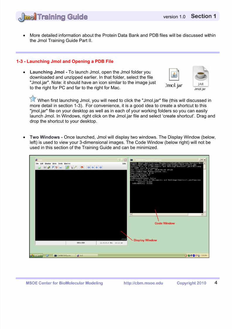
Jmol File Location – The Jmol folder contains all the files your computer needs to run Jmol,and they need to be kept together in the same folder. You may save this folder in anyconvenient location on your computer. Jmol does not need to be "installed", so once thesefiles are in place on your computer, the program will be ready to use.
When first launching Jmol, you will need to click the "Jmol.jar" file (this will discussed inmore detail in section 1-3). For convenience, it is a good idea to create a shortcut to this"jmol.jar" file on your desktop as well as in each of your working folders so you can easilylaunch Jmol. In Windows, right click on the Jmol.jar file and select ‘create shortcut’. Drag and
drop the shortcut to your desktop.
1-2 - Protein Data Bank (PDB) Files
Molecular structures can be determined through the use of X-ray Crystallography, NuclearMagnetic Resonance (NMR), or computer algorithm-based calculations.
7/25/2019 JMol Training Guide
http://slidepdf.com/reader/full/jmol-training-guide 6/40
3
version 1.0
Once a structure has been determined, each atom in the structure is assigned an (X,Y,Z)coordinate to mark its location in 3-dimensional space. These coordinates are then stored ina file called a Protein Data Bank (PDB) file.
Molecular visualization software, such as Jmol, can then use the coordinates stored in a PDBfile to create an interactive 3-dimensional visualization of a molecular structure.
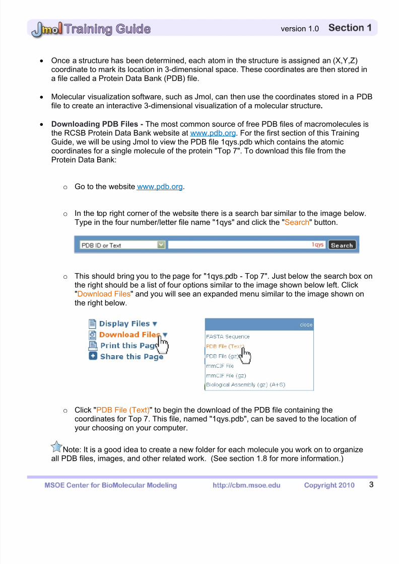
Downloading PDB Files - The most common source of free PDB files of macromolecules isthe RCSB Protein Data Bank website at UUwww.pdb.orgUU. For the first section of this TrainingGuide, we will be using Jmol to view the PDB file 1qys.pdb which contains the atomiccoordinates for a single molecule of the protein "Top 7". To download this file from theProtein Data Bank:
o Go to the website UUwww.pdb.orgUU.
o In the top right corner of the website there is a search bar similar to the image below.Type in the four number/letter file name "1qys" and click the "Search" button.
o This should bring you to the page for "1qys.pdb - Top 7". Just below the search box onthe right should be a list of four options similar to the image shown below left. Click
"Download Files" and
you will see an expanded menu similar to the image shown onthe right below.
o Click "PDB File (Text)" to begin the download of the PDB file containing thecoordinates for Top 7. This file, named "1qys.pdb", can be saved to the location ofyour choosing on your computer.
Note: It is a good idea to create a new folder for each molecule you work on to organizeall PDB files, images, and other related work. (See section 1.8 for more information.)
7/25/2019 JMol Training Guide
http://slidepdf.com/reader/full/jmol-training-guide 7/40
7/25/2019 JMol Training Guide
http://slidepdf.com/reader/full/jmol-training-guide 8/40
5
version 1.0
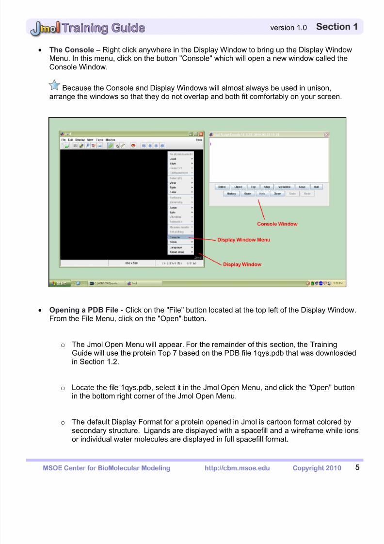
The Console – Right click anywhere in the Display Window to bring up the Display WindowMenu. In this menu, click on the button "Console" which will open a new window called theConsole Window.
Because the Console and Display Windows will almost always be used in unison,
arrange the windows so that they do not overlap and both fit comfortably on your screen.
Opening a PDB File - Click on the "File" button located at the top left of the Display Window.From the File Menu, click on the "Open" button.
o The Jmol Open Menu will appear. For the remainder of this section, the TrainingGuide will use the protein Top 7 based on the PDB file 1qys.pdb that was downloadedin Section 1.2.
o Locate the file 1qys.pdb, select it in the Jmol Open Menu, and click the "Open" buttonin the bottom right corner of the Jmol Open Menu.
o The default Display Format for a protein opened in Jmol is cartoon format colored bysecondary structure. Ligands are displayed with a spacefill and a wireframe while ionsor individual water molecules are displayed in full spacefill format.
7/25/2019 JMol Training Guide
http://slidepdf.com/reader/full/jmol-training-guide 9/40
6
version 1.0
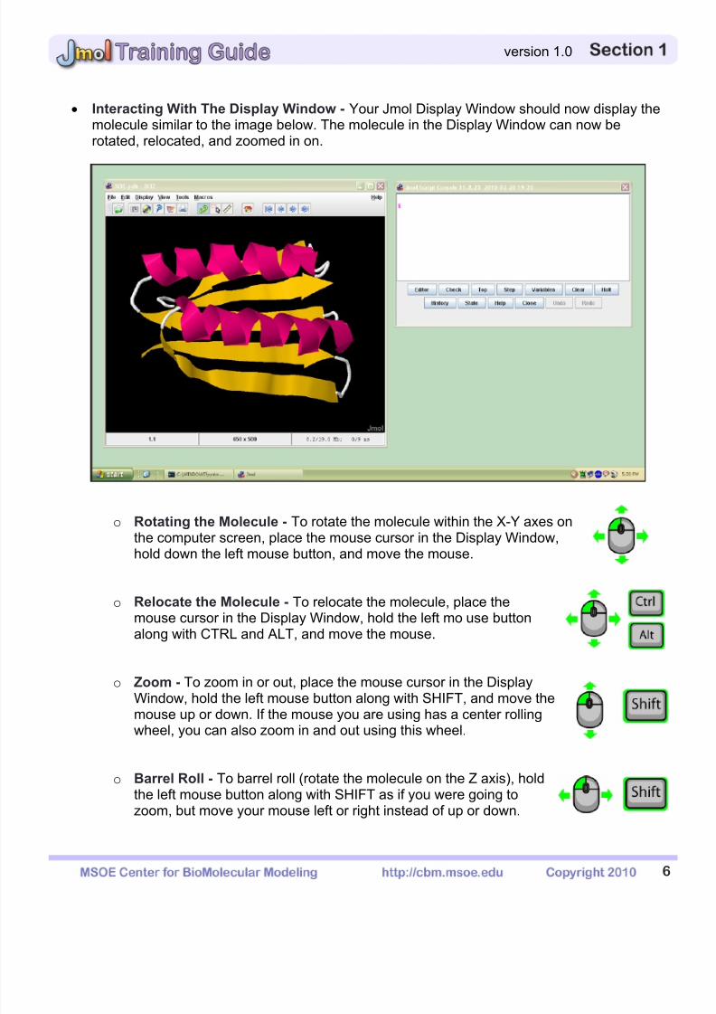
Interacting With The Display Window - Your Jmol Display Window should now display themolecule similar to the image below. The molecule in the Display Window can now berotated, relocated, and zoomed in on.
o Rotating the Molecule - To rotate the molecule within the X-Y axes on
the computer screen, place the mouse cursor in the Display Window,UUhold down the left UU mouse button, and move the mouse.
o Relocate the Molecule - To relocate the molecule, place themouse cursor in the Display Window, hold the left mo
use buttonalong with CTRL and ALT, and move the mouse.
o Zoom - To zoom in or out, place the mouse cursor in the DisplayWindow, hold the left mouse button along with SHIFT, and move the
mouse up or down. If the mouse you are using has a center rollingwheel, you can also zoom in and out using this wheel.
o Barrel Roll - To barrel roll (rotate the molecule on the Z axis), holdthe left mouse button along with SHIFT as if you were going tozoom, but move your mouse left or right instead of up or down.

7/25/2019 JMol Training Guide
http://slidepdf.com/reader/full/jmol-training-guide 10/40
7
version 1.0
1-4 - The Command Line and Common Display Formats and Display Colors
The Command Line - If you click in the white area of the Console Window, you will enter theCommand Line. This area, highlighted by a magenta dollar sign ($), is where text commands
are entered. After typing a command and hitting enter, the 3-dimensional image of yourmolecule in the Display Window will change.
If you have typed a command incorrectly or the command is not recognized by Jmol, thetext in the command line that is normally black will turn red.
Different Display Formats - The first text commands we will explore are the DisplayFormats. These key terms, when typed into the command line, will let you change the wayyour molecule is displayed. Below is a description of each of the common Display Formatsalong with an image of how the Top 7 from 1qys.pdb looks when this command is entered.
o Wireframe - The thin wire represents the bondsbetween atoms and the ends of the wires representthe locations of the atoms. The advantage of thewireframe is that all of the atoms are displayed.However, it is difficult to distinguish secondarystructures in this format.
To turn this format on, type wireframe on
To turn this format off, type wireframe off
o Backbone - The alpha carbon backbone formatonly displays the position of the alpha carbon ineach amino acid by a bend in the backbone. All ofthe other atoms within the amino acid are notdisplayed. The advantage of this display format isthat it clearly illustrates the secondary structureswithin a molecule.
To turn this format on, type backbone on
To turn this format off, type backbone off
7/25/2019 JMol Training Guide
http://slidepdf.com/reader/full/jmol-training-guide 11/40
8
version 1.0
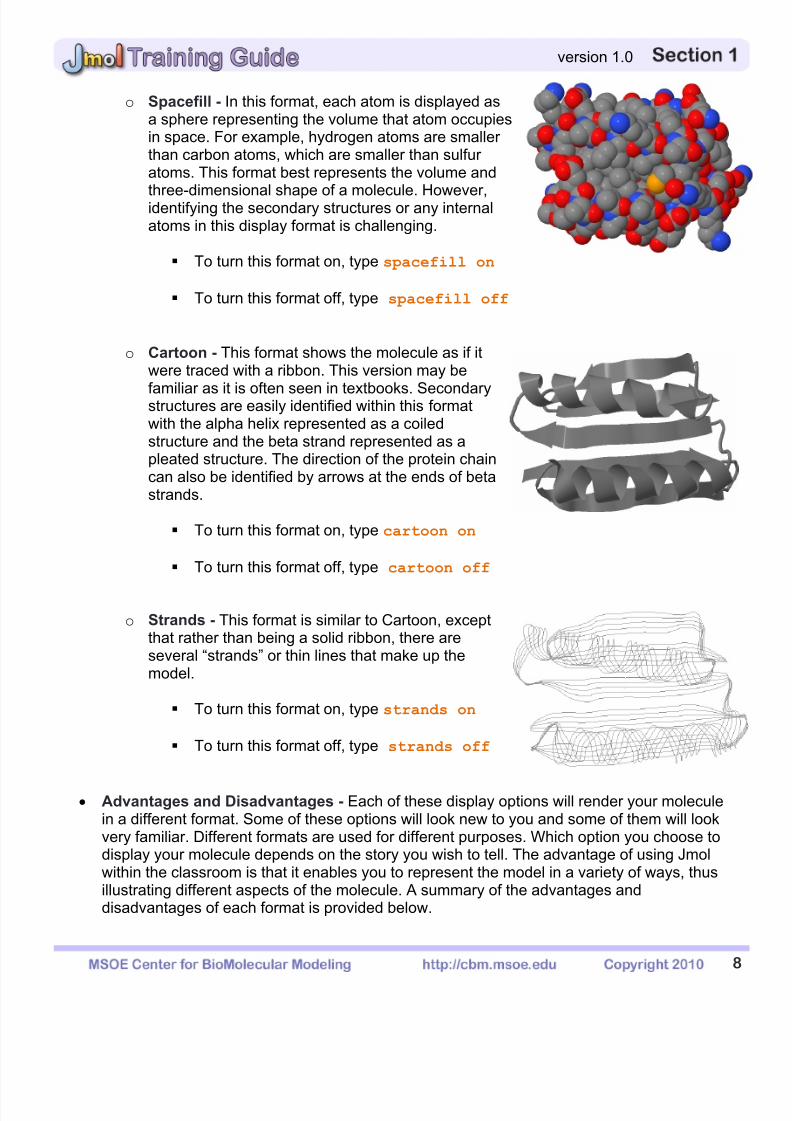
o Spacefill - In this format, each atom is displayed asa sphere representing the volume that atom occupiesin space. For example, hydrogen atoms are smallerthan carbon atoms, which are smaller than sulfuratoms. This format best represents the volume and
three-dimensional shape of a molecule. However,identifying the secondary structures or any internalatoms in this display format is challenging.
To turn this format on, type spacefill on
To turn this format off, type spacefill off
o Cartoon - This format shows the molecule as if itwere traced with a ribbon. This version may be
familiar as it is often seen in textbooks. Secondarystructures are easily identified within this formatwith the alpha helix represented as a coiledstructure and the beta strand represented as apleated structure. The direction of the protein chaincan also be identified by arrows at the ends of betastrands.
To turn this format on, type cartoon on
To turn this format off, type cartoon off
o Strands - This format is similar to Cartoon, exceptthat rather than being a solid ribbon, there areseveral “strands” or thin lines that make up themodel.
To turn this format on, type strands on
To turn this format off, type strands off
Advantages and Disadvantages - Each of these display options will render your moleculein a different format. Some of these options will look new to you and some of them will lookvery familiar. Different formats are used for different purposes. Which option you choose todisplay your molecule depends on the story you wish to tell. The advantage of using Jmolwithin the classroom is that it enables you to represent the model in a variety of ways, thusillustrating different aspects of the molecule. A summary of the advantages anddisadvantages of each format is provided below.
7/25/2019 JMol Training Guide
http://slidepdf.com/reader/full/jmol-training-guide 12/40
9
version 1.0
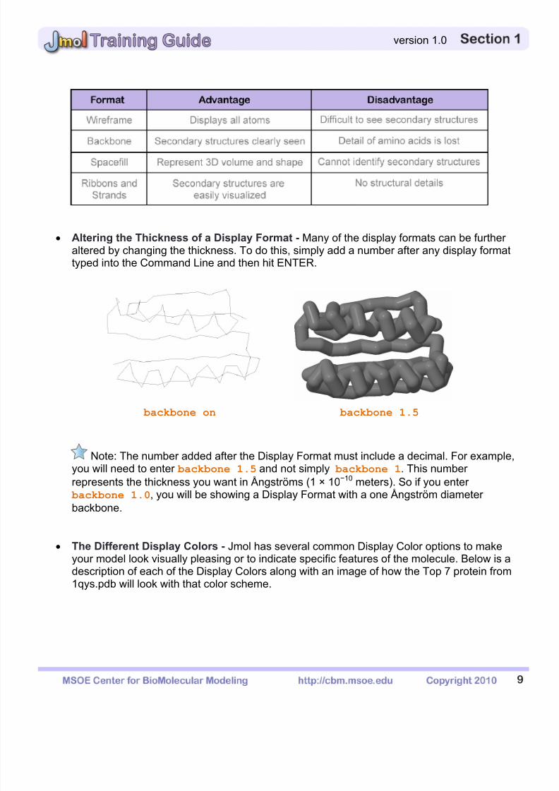
Altering the Thickness of a Display Format - Many of the display formats can be furtheraltered by changing the thickness. To do this, simply add a number after any display formattyped into the Command Line and then hit ENTER.
backbone on backbone 1.5
Note: The number added after the Display Format must include a decimal. For example,you will need to enter backbone 1.5 and not simply backbone 1. This numberrepresents the thickness you want in Ångströms (1 × 10⁻¹⁰ meters). So if you enter backbone 1.0, you will be showing a Display Format with a one Ångström diameter
backbone.
The Different Display Colors - Jmol has several common Display Color options to makeyour model look visually pleasing or to indicate specific features of the molecule. Below is adescription of each of the Display Colors along with an image of how the Top 7 protein from1qys.pdb will look with that color scheme.
7/25/2019 JMol Training Guide
http://slidepdf.com/reader/full/jmol-training-guide 13/40
1
version 1.0
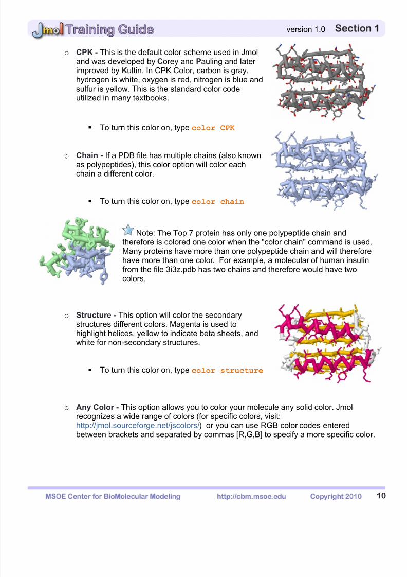
o CPK - This is the default color scheme used in Jmoland was developed by Corey and Pauling and laterimproved by Kultin. In CPK Color, carbon is gray,hydrogen is white, oxygen is red, nitrogen is blue andsulfur is yellow. This is the standard color code
utilized in many textbooks.
To turn this color on, type color CPK
o Chain - If a PDB file has multiple chains (also knownas polypeptides), this color option will color eachchain a different color.
To turn this color on, type color chain
Note: The Top 7 protein has only one polypeptide chain andtherefore is colored one color when the "color chain" command is used.Many proteins have more than one polypeptide chain and will thereforehave more than one color. For example, a molecular of human insulinfrom the file 3i3z.pdb has two chains and therefore would have twocolors.
o Structure - This option will color the secondarystructures different colors. Magenta is used tohighlight helices, yellow to indicate beta sheets, andwhite for non-secondary structures.
To turn this color on, type color structure
o Any Color - This option allows you to color your molecule any solid color. Jmolrecognizes a wide range of colors (for specific colors, visit:http://jmol.sourceforge.net/jscolors/) or you can use RGB color codes enteredbetween brackets and separated by commas [R,G,B] to specify a more specific color.

7/25/2019 JMol Training Guide
http://slidepdf.com/reader/full/jmol-training-guide 14/40
1
version 1.0
color red color [0,255,100]
Background Color of the Display Window - The default color for the background of theDisplay Window will be black. This can be modified by using the color backgroundcommand followed by the color you wish to change the background to.
color background white color background magenta
Note: We recommend that you avoid the red/green color combination in case you, orothers, have problems with color blindness. Bright background colors from a computermonitor are also often hard on the eyes and therefore make it more difficult to focus on theprotein. When creating an image for use on a poster, it is best to use a white background.
7/25/2019 JMol Training Guide
http://slidepdf.com/reader/full/jmol-training-guide 15/40
1
version 1.0
1-5 - The Select Command
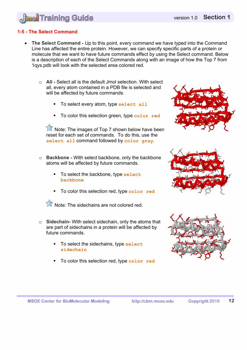
The Select Command - Up to this point, every command we have typed into the CommandLine has affected the entire protein. However, we can specify specific parts of a protein ormolecule that we want to have future commands effect by using the Select command. Below
is a description of each of the Select Commands along with an image of how the Top 7 from1qys.pdb will look with the selected area colored red.
o All - Select all is the default Jmol selection. With selectall, every atom contained in a PDB file is selected andwill be affected by future commands.
To select every atom, type select all
To color this selection green, type color red
Note: The images of Top 7 shown below have beenreset for each set of commands. To do this, use theselect all command followed by color gray.
o Backbone - With select backbone, only the backboneatoms will be affected by future commands.
To select the backbone, type select
backbone
To color this selection red, type color red
Note: The sidechains are not colored red.
o Sidechain- With select sidechain, only the atoms thatare part of sidechains in a protein will be affected byfuture commands.
To select the sidechains, type selectsidechain
To color this selection red, type color red
7/25/2019 JMol Training Guide
http://slidepdf.com/reader/full/jmol-training-guide 16/40
1
version 1.0
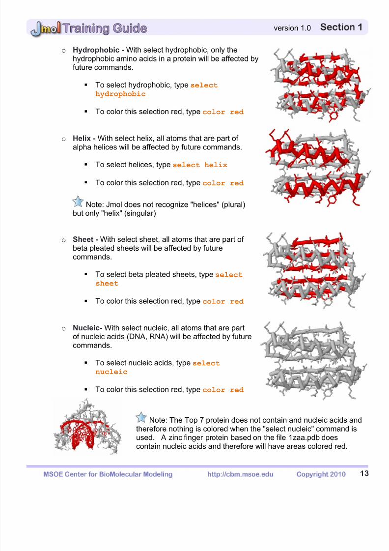
o Hydrophobic - With select hydrophobic, only thehydrophobic amino acids in a protein will be affected byfuture commands.
To select hydrophobic, type select
hydrophobic
To color this selection red, type color red
o Helix - With select helix, all atoms that are part ofalpha helices will be affected by future commands.
To select helices, type select helix
To color this selection red, type color red
Note: Jmol does not recognize "helices" (plural)but only "helix" (singular)
o Sheet - With select sheet, all atoms that are part ofbeta pleated sheets will be affected by futurecommands.
To select beta pleated sheets, type select
sheet
To color this selection red, type color red
o Nucleic- With select nucleic, all atoms that are partof nucleic acids (DNA, RNA) will be affected by futurecommands.
To select nucleic acids, type select
nucleic
To color this selection red, type color red
Note: The Top 7 protein does not contain and nucleic acids andtherefore nothing is colored when the "select nucleic" command isused. A zinc finger protein based on the file 1zaa.pdb doescontain nucleic acids and therefore will have areas colored red.

7/25/2019 JMol Training Guide
http://slidepdf.com/reader/full/jmol-training-guide 17/40
1
version 1.0
o Water- With select water, all water molecules will beaffected by future commands.
To select water molecules, type select
water
To display water molecules, type spacefill
To color this selection red, type color red
o Chain- With select chain * followed by the letter of thechain you would like to select, only the chain youselect will be affected by future commands.
To select chain A, type select *a
To color this selection red, type color red
o Residue Number- With the Residue Number selectcommand, you can select a specific amino acid or arange of amino acids that all future commands willaffect.
To select residue number 15, type select 15
To color this selection red, type color red
To select residues 20 through 30, type select
10-20
To color this selection red, type color red
Note: You can also select an amino acid by itsthree letter abbreviation followed by the ResidueNumber. For example, instead of select 15 as shown above, you could also useselect lys15 because the amino acid at Residue Number 15 in the Top 7 protein isa Lysine.

7/25/2019 JMol Training Guide
http://slidepdf.com/reader/full/jmol-training-guide 18/40
1
version 1.0
o Atom Number- With the Atom Number selectcommand, you can select a specific atom number orrange of atoms that all future commands will affect.
To select atom number 317, type selectatomno=317
To color this selection green, type color red
o Atom Number Range- With an alteration to the AtomNumber select command, you can select a range ofatoms that all future commands will affect.
To select atom number 303-410, type selectatomno>= 303 and atomno<= 410
To color this selection green, type color red
Note: If you do not know the Residue Number, Chain, Amino Acid Type, or the AtomNumber you want to select, you can click on the residue in the Display Window. Clicking onan atom will result in information about that atom appearing in the Console Window. Theimage below explains this information in more detail:
7/25/2019 JMol Training Guide
http://slidepdf.com/reader/full/jmol-training-guide 19/40
1
version 1.0
1-6 - Boolean Operators
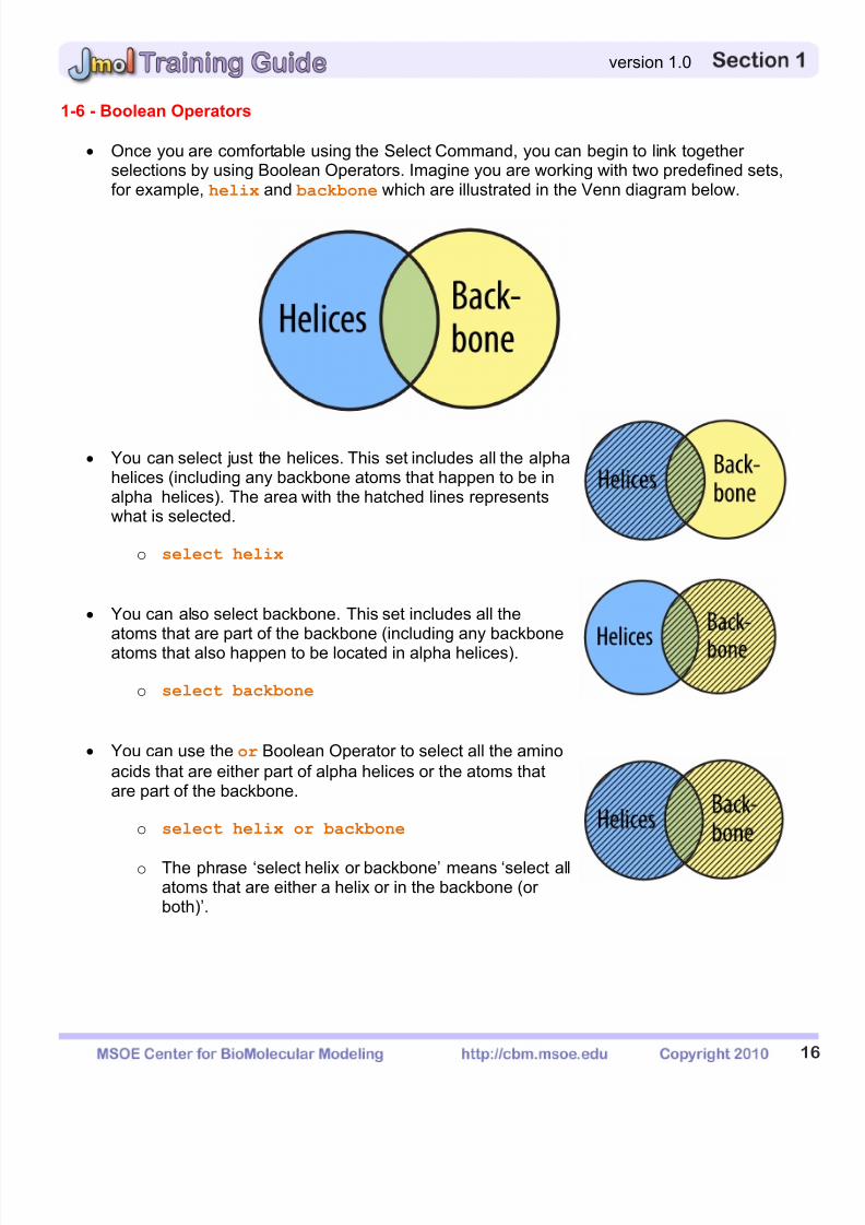
Once you are comfortable using the Select Command, you can begin to link togetherselections by using Boolean Operators. Imagine you are working with two predefined sets,for example, helix and backbone which are illustrated in the Venn diagram below.
You can select just the helices. This set includes all the alphahelices (including any backbone atoms that happen to be inalpha helices). The area with the hatched lines representswhat is selected.
o select helix
You can also select backbone. This set includes all theatoms that are part of the backbone (including any backboneatoms that also happen to be located in alpha helices).
o select backbone
You can use the or Boolean Operator to select all the aminoacids that are either part of alpha helices or the atoms thatare part of the backbone.
o select helix or backbone
o The phrase ‘select helix or backbone’ means ‘select allatoms that are either a helix or in the backbone (orboth)’.
7/25/2019 JMol Training Guide
http://slidepdf.com/reader/full/jmol-training-guide 20/40
1
version 1.0
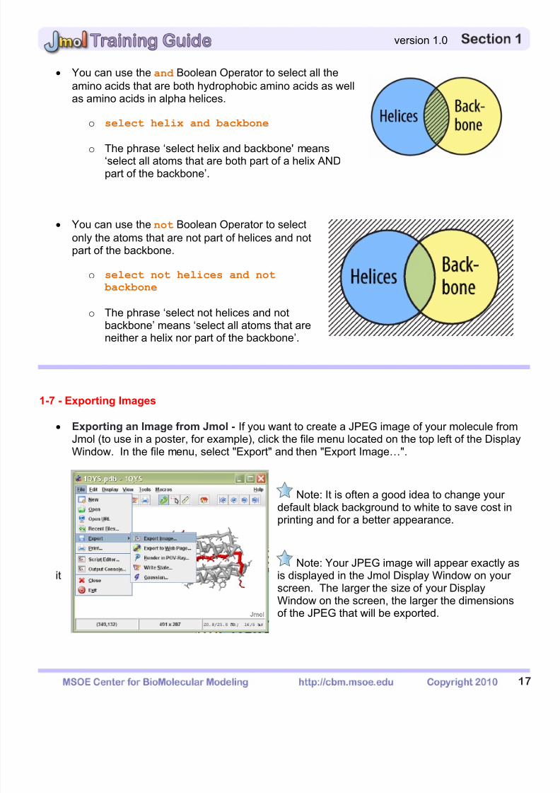
You can use the and Boolean Operator to select all theamino acids that are both hydrophobic amino acids as wellas amino acids in alpha helices.
o select helix and backbone
o The phrase ‘select helix and backbone' means‘select all atoms that are both part of a helix ANDpart of the backbone’.
You can use the not Boolean Operator to selectonly the atoms that are not part of helices and notpart of the backbone.
o select not helices and not backbone
o The phrase ‘select not helices and notbackbone’ means ‘select all atoms that areneither a helix nor part of the backbone’.
1-7 - Exporting Images
Exporting an Image from Jmol - If you want to create a JPEG image of your molecule fromJmol (to use in a poster, for example), click the file menu located on the top left of the DisplayWindow. In the file menu, select "Export" and then "Export Image…".
Note: It is often a good idea to change yourdefault black background to white to save cost inprinting and for a better appearance.
Note: Your JPEG image will appear exactly asit is displayed in the Jmol Display Window on your
screen. The larger the size of your DisplayWindow on the screen, the larger the dimensionsof the JPEG that will be exported.

7/25/2019 JMol Training Guide
http://slidepdf.com/reader/full/jmol-training-guide 21/40
1
version 1.0
1-8 - Saving Your Work and Organizing Your Files
Saving Your Work - If you would like to save your work while working in Jmol, you simplyexport a JPEG file following the exact same directions shown in section 1-7. These JPEG
files, even though they appear to be regular images, also contain information on what PDBfile you have used and what commands you have entered. We recommend that you saveyour work frequently using sequential numbers
o For example: Filename1.jpgFilename2.jpgFilename3.jpg
Organizing Files - We recommend that you create a folder for each molecule you aredesigning. In this folder, place the following files:
o Shortcut to Jmol
o PDB file being used
o All exported JPEG files
Note: We recommend the folder organization shown above because, in order for yoursaved work from your JPEG to load properly, you must have the PDB file and the JPEGfile located in the same folder on your computer. When exporting a JPEG to save yourwork, save your file to this same folder.
Loading Your Saved Work - To load your saved work from the JPEG that you have created,simply drag the JPG from the folder onto the Display Window. This will bring your saved workback up in Jmol.
Sending Your Saved Work - When you are ready to send your saved model designs forreview or 3D Printing, attach the exported JPEG file to an e-mail. If the PDB file that wasused to generate the model design and JPEG is not a standard PDB file available from
www.pdb.org, the PDB file will need to be sent along as an e-mail attachment as well.
7/25/2019 JMol Training Guide
http://slidepdf.com/reader/full/jmol-training-guide 22/40
1
version 1.0
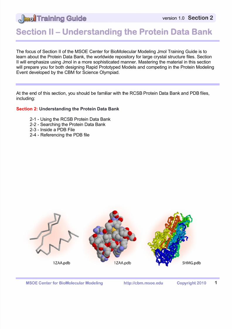
Section II – Understanding the Protein Data ank
The focus of Section II of the MSOE Center for BioMolecular Modeling Jmol Training Guide is to
learn about the Protein Data Bank, the worldwide repository for large crystal structure files. SectionII will emphasize using Jmol in a more sophisticated manner. Mastering the material in this sectionwill prepare you for both designing Rapid Prototyped Models and competing in the Protein ModelingEvent developed by the CBM for Science Olympiad.
At the end of this section, you should be familiar with the RCSB Protein Data Bank and PDB files,including:
Section 2: Understanding the Protein Data Bank
2-1 - Using the RCSB Protein Data Bank2-2 - Searching the Protein Data Bank2-3 - Inside a PDB File2-4 - Referencing the PDB file
7/25/2019 JMol Training Guide
http://slidepdf.com/reader/full/jmol-training-guide 23/40
2
version 1.0
2-1 - Using the RCSB Protein Data Bank
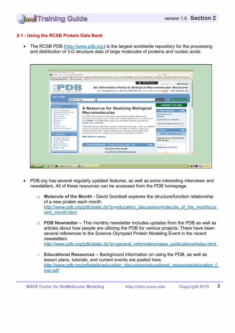
The RCSB PDB (http://www.pdb.org) is the largest worldwide repository for the processingand distribution of 3-D structure data of large molecules of proteins and nucleic acids.
PDB.org has several regularly updated features, as well as some interesting interviews andnewsletters. All of these resources can be accessed from the PDB homepage.
o Molecule of the Month - David Goodsell explores the structure/function relationship
of a new protein each month.http://www.pdb.org/pdb/static.do?p=education_discussion/molecule_of_the_month/cur rent_month.html
o PDB Newsletter – This monthly newsletter includes updates from the PDB as well asarticles about how people are utilizing the PDB for various projects. There have been
several references to the Science Olympiad Protein Modeling Event in the recentnewsletters.http://www.pdb.org/pdb/static.do?p=general_information/news_publications/index.html
o Educational Resources – Background information on using the PDB, as well aslesson plans, tutorials, and current events are posted here.http://www.pdb.org/pdbstatic/education_discussion/educational_resources/education_f lyer.pdf
7/25/2019 JMol Training Guide
http://slidepdf.com/reader/full/jmol-training-guide 24/40
3
version 1.0
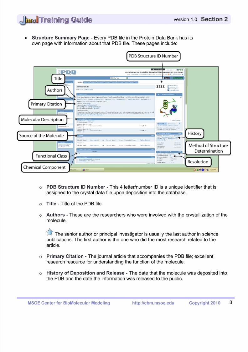
Structure Summary Page - Every PDB file in the Protein Data Bank has itsown page with information about that PDB file. These pages include:
o PDB Structure ID Number - This 4 letter/number ID is a unique identifier that isassigned to the crystal data file upon deposition into the database.
o Title - Title of the PDB file
o Authors - These are the researchers who were involved with the crystallization of themolecule.
The senior author or principal investigator is usually the last author in sciencepublications. The first author is the one who did the most research related to the
article.
o Primary Citation - The journal article that accompanies the PDB file; excellentresearch resource for understanding the function of the molecule.
o History of Deposition and Release - The date that the molecule was deposited intothe PDB and the date the information was released to the public.
7/25/2019 JMol Training Guide
http://slidepdf.com/reader/full/jmol-training-guide 25/40
4
version 1.0
o Method of Structure Determination - The method that was used toobtain the structural data (ex: NMR, X-ray diffraction).
o Resolution – This indicates how accurately the position of each atom wasdetermined. The smaller the number, the better the data.
o Molecular Description - This indicates the number of chains within the molecule andthe chain identity; for example in the hemoglobin file (1A3N.pdb), chains A and C arethe alpha-globin molecules and chains B and D are the beta-globin molecules.
o Functional Class - What type of molecule is it? (Ex: a toxin, an enzyme)
o Source of the Molecule - From which species was the molecule isolated? (human,bacterium, virus, mouse)
o Chemical Component - Heterologous groups that were cocrystallized with the
molecule are listed here. Not all PDB files will have this section.
The 2-3 letter identifier used to designate the chemical components containedwithin the file listed are recognized by Jmol.
For example, if NAG (N-acetyl-glucosamine) is contained within the crystal,Jmol recognizes “NAG” for this file. If you enter the command “select NAG”Jmol would recognize the atoms within that chemical component of the PDBfile.
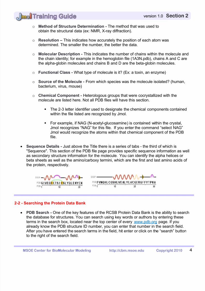
Sequence Details - Just above the Title there is a series of tabs - the third of which is
"Sequence". This section of the PDB file page provides specific sequence information as wellas secondary structure information for the molecule. You can identify the alpha helices orbeta sheets as well as the amino/carboxy termini, which are the first and last amino acids ofthe protein, respectively.
2-2 - Searching the Protein Data Bank
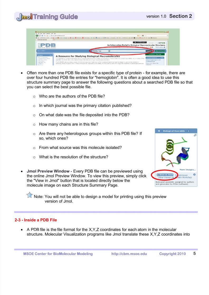
PDB Search - One of the key features of the RCSB Protein Data Bank is the ability to searchthe database for structures. You can search using key words or authors by entering theseterms in the search box, located near the top center of every www.pdb.org page. If youalready know the PDB structure ID number, you can enter that number in the search field.
After you have entered the search terms in the field, hit enter or click on the “search” buttonto the right of the search field.
7/25/2019 JMol Training Guide
http://slidepdf.com/reader/full/jmol-training-guide 26/40
5
version 1.0
Often more than one PDB file exists for a specific type of protein - for example, there areover four hundred PDB file entries for "hemoglobin". It is often a good idea to use thisstructure summary page to answer the following questions about a searched PDB file so thatyou can select the best possible file.
o Who are the authors of the PDB file?
o In which journal was the primary citation published?
o On what date was the file deposited into the PDB?
o How many chains are in this file?
o Are there any heterologous groups within this PDB file? Ifso, which ones?
o From what source was this molecule isolated?
o What is the resolution of the structure?
Jmol Preview Window - Every PDB file can be previewed usingthe online Jmol Preview Window. To view this preview, simply clickthe "View in Jmol" button that is located directly below themolecule image on each Structure Summary Page.
Note: You will not be able to design a model for printing using this previewversion of Jmol.
2-3 - Inside a PDB File
A PDB file is the file format for the X,Y,Z coordinates for each atom in the molecularstructure. Molecular Visualization programs like Jmol translate these X,Y,Z coordinates into

7/25/2019 JMol Training Guide
http://slidepdf.com/reader/full/jmol-training-guide 27/40
6
version 1.0
interactive 3-dimensional images, but you can also examine the file directly by opening it inany number of text editing programs such as Microsoft Word or Wordpad.
Most PDB Files will begin with written information, termed the "Header", about the structure,the lab that determined it, and the techniques used in the lab. Any comments like this will
always start with the word "REMARK" and are ignored by Jmol. The information used tocreate the Structure Summary page of the RCSB PDB for each PDB file is included intheHeader.
The main portion of a PDB file will be the X,Y,Z coordinates. Although there are severalsimilar versions of the nomenclature used to record these coordinates, the basic informationremains the same. Below is a sample set of coordinates from a PDB file that has beenopened with text editing software.
2-4 - Referencing the PDB
PDB Search - When you use a PDB file to create an image or a model, you must cite the PDB filein your reference list. A PDB structure entry should be cited with its PDB ID and primary reference.For example:
PDB ID: 1QYS. Kuhlman, B., Dantas, G. Ireton, G.C., Varani, G., Stoddard, B.C., Baker, D.(2003). Design of a Novel Globular Protein Fold with Atomic Level Accuracy. Science 302;1364-1368.

7/25/2019 JMol Training Guide
http://slidepdf.com/reader/full/jmol-training-guide 28/40
1
version 1.0
Section III Designing Models for 3D Printing
Through this section of the Jmol Training Guide, you will become familiar with the commands
needed to design a model that will be built on a 3D Printer. As you become more comfortable usingJmol, this section will enable you to take the next step and design physical protein models.
At the end of this section, you should be familiar with how to use Jmol to create a physical proteinmodel on a rapid prototyping machine, including:
Section 3: Designing Models for 3D Printing
3-1 - What is 3D Printing?
3-2 - Selecting Appropriate Display Formats and Colors3-3 - Adding and Removing Hydrogen Bonds and Disulfide Bonds3-4 - Adding and Removing Support Struts3-5 - Coloring Hydrogen Bonds, SS Bonds, and Struts3-6 - Adding Sidechains with a “Clean Backbone"3-7 - Additional Miscellaneous Jmol Commands
7/25/2019 JMol Training Guide
http://slidepdf.com/reader/full/jmol-training-guide 29/40
2
version 1.0
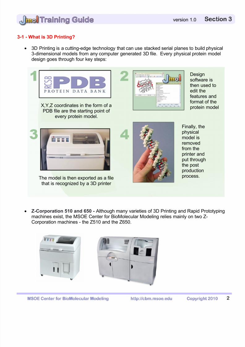
3-1 - What is 3D Printing?
3D Printing is a cutting-edge technology that can use stacked serial planes to build physical3-dimensional models from any computer generated 3D file. Every physical protein model
design goes through four key steps:
Z-Corporation 510 and 650 - Although many varieties of 3D Printing and Rapid Prototypingmachines exist, the MSOE Center for BioMolecular Modeling relies mainly on two Z-Corporation machines - the Z510 and the Z650.
X,Y,Z coordinates in the form of aPDB file are the starting point of
every protein model.
Designsoftware isthen used toedit thefeatures andformat of theprotein model
The model is then exported as a file
that is recognized by a 3D printer
Finally, thephysicalmodel isremovedfrom theprinter andput throughthe postproductionprocess.
7/25/2019 JMol Training Guide
http://slidepdf.com/reader/full/jmol-training-guide 30/40
3
version 1.0
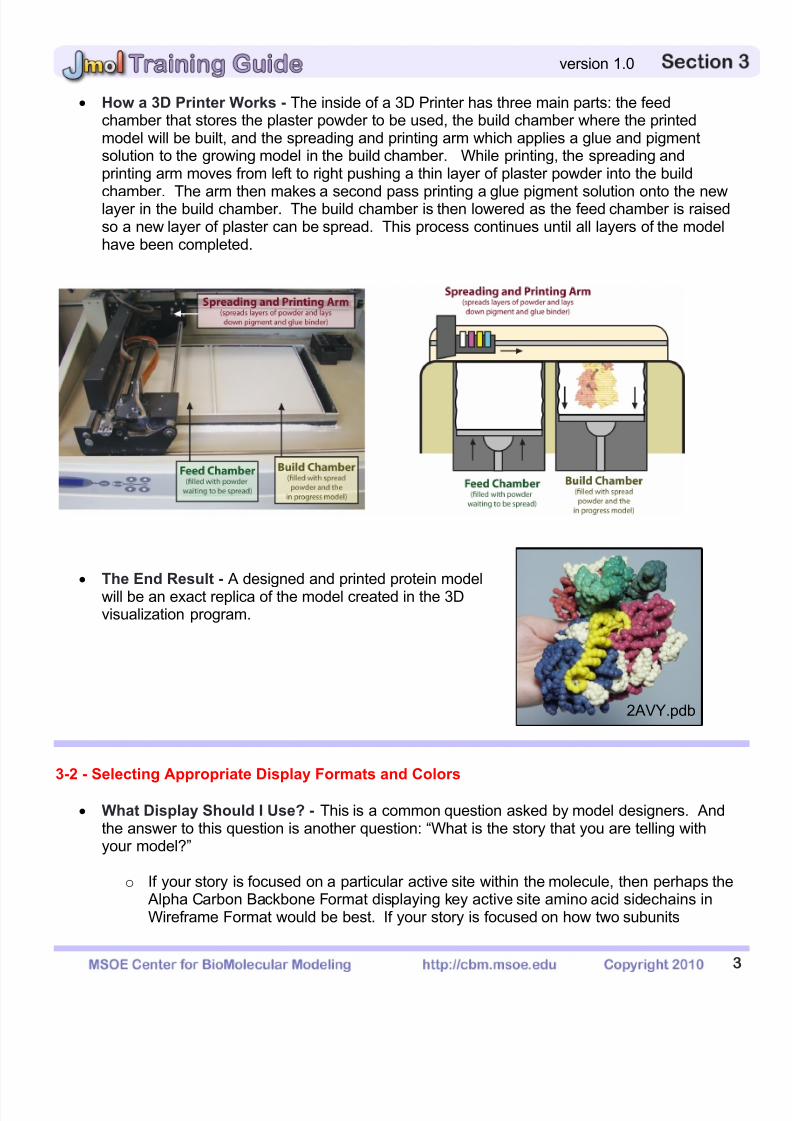
How a 3D Printer Works - The inside of a 3D Printer has three main parts: the feedchamber that stores the plaster powder to be used, the build chamber where the printedmodel will be built, and the spreading and printing arm which applies a glue and pigmentsolution to the growing model in the build chamber. While printing, the spreading andprinting arm moves from left to right pushing a thin layer of plaster powder into the build
chamber. The arm then makes a second pass printing a glue pigment solution onto the newlayer in the build chamber. The build chamber is then lowered as the feed chamber is raisedso a new layer of plaster can be spread. This process continues until all layers of the modelhave been completed.
The End Result - A designed and printed protein modelwill be an exact replica of the model created in the 3Dvisualization program.
3-2 - Selecting Appropriate Display Formats and Colors
What Display Should I Use? - This is a common question asked by model designers. Andthe answer to this question is another question: “What is the story that you are telling withyour model?”
o If your story is focused on a particular active site within the molecule, then perhaps the Alpha Carbon Backbone Format displaying key active site amino acid sidechains inWireframe Format would be best. If your story is focused on how two subunits
2AVY.pdb
7/25/2019 JMol Training Guide
http://slidepdf.com/reader/full/jmol-training-guide 31/40
4
version 1.0
interface at the surface, then perhaps the Spacefill Format is the best choice.Ultimately the choice is yours. In Section I, there is a table highlighting theadvantages and disadvantages of each display format. This will assist you in decidingwhich format is the best for telling your story.
o The important point to remember is that no one model will tell every aspect of thestory. Using Jmol in combination with a physical model will assist you in tellingmultiple aspects of your story.
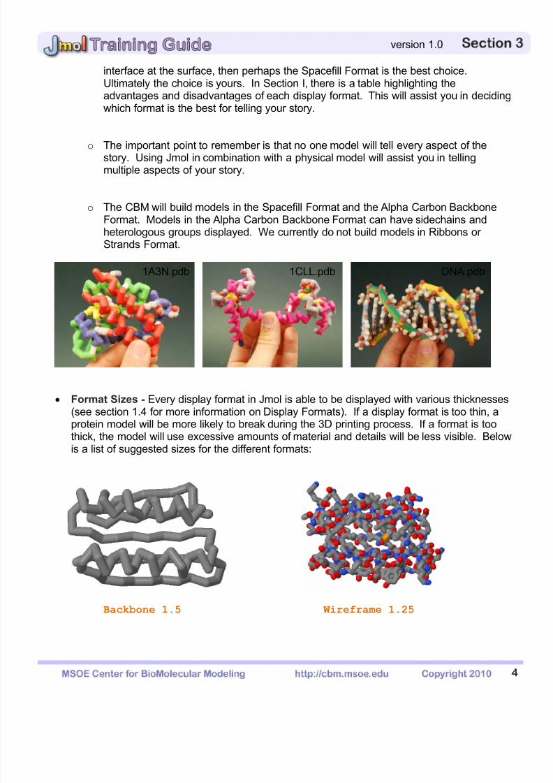
o The CBM will build models in the Spacefill Format and the Alpha Carbon BackboneFormat. Models in the Alpha Carbon Backbone Format can have sidechains andheterologous groups displayed. We currently do not build models in Ribbons orStrands Format.
Format Sizes - Every display format in Jmol is able to be displayed with various thicknesses
(see section 1.4 for more information on Display Formats). If a display format is too thin, aprotein model will be more likely to break during the 3D printing process. If a format is toothick, the model will use excessive amounts of material and details will be less visible. Belowis a list of suggested sizes for the different formats:
Backbone 1.5 Wireframe 1.25
1A3N.pdb 1CLL.pdb DNA.pdb
7/25/2019 JMol Training Guide
http://slidepdf.com/reader/full/jmol-training-guide 32/40
5
version 1.0
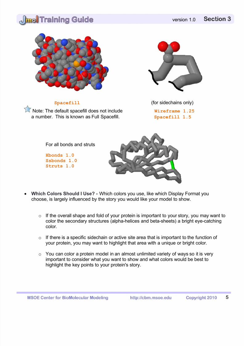
Spacefill (for sidechains only)
Note: The default spacefill does not include Wireframe 1.25
a number. This is known as Full Spacefill. Spacefill 1.5
For all bonds and struts
Hbonds 1.0
Ssbonds 1.0
Struts 1.0
Which Colors Should I Use? - Which colors you use, like which Display Format youchoose, is largely influenced by the story you would like your model to show.
o If the overall shape and fold of your protein is important to your story, you may want tocolor the secondary structures (alpha-helices and beta-sheets) a bright eye-catchingcolor.
o If there is a specific sidechain or active site area that is important to the function of
your protein, you may want to highlight that area with a unique or bright color.
o You can color a protein model in an almost unlimited variety of ways so it is veryimportant to consider what you want to show and what colors would be best tohighlight the key points to your protein's story.
7/25/2019 JMol Training Guide
http://slidepdf.com/reader/full/jmol-training-guide 33/40
6
version 1.0
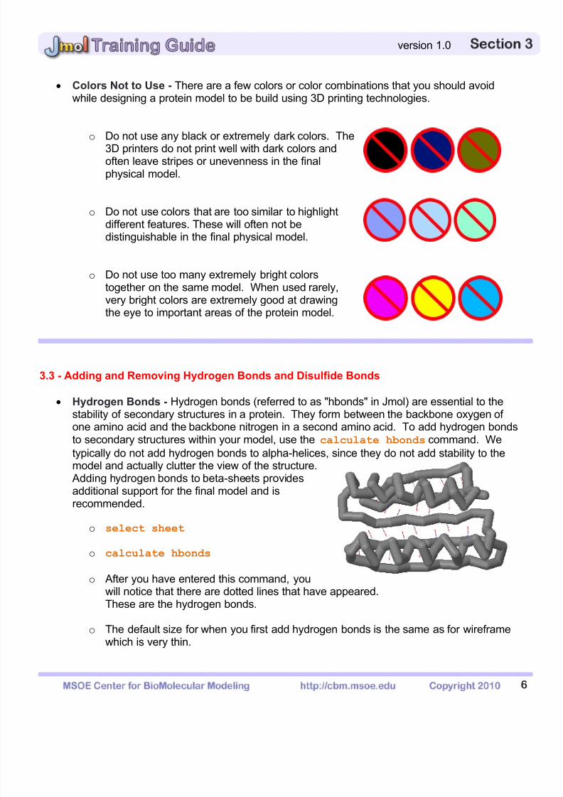
Colors Not to Use - There are a few colors or color combinations that you should avoidwhile designing a protein model to be build using 3D printing technologies.
o Do not use any black or extremely dark colors. The3D printers do not print well with dark colors andoften leave stripes or unevenness in the finalphysical model.
o Do not use colors that are too similar to highlightdifferent features. These will often not bedistinguishable in the final physical model.
o
Do not use too many extremely bright colorstogether on the same model. When used rarely,very bright colors are extremely good at drawingthe eye to important areas of the protein model.
3.3 - Adding and Removing Hydrogen Bonds and Disulfide Bonds
Hydrogen Bonds - Hydrogen bonds (referred to as "hbonds" in Jmol) are essential to the
stability of secondary structures in a protein. They form between the backbone oxygen ofone amino acid and the backbone nitrogen in a second amino acid. To add hydrogen bondsto secondary structures within your model, use the calculate hbonds command. We
typically do not add hydrogen bonds to alpha-helices, since they do not add stability to themodel and actually clutter the view of the structure.
Adding hydrogen bonds to beta-sheets providesadditional support for the final model and isrecommended.
o select sheet
o
calculate hbonds
o After you have entered this command, youwill notice that there are dotted lines that have appeared.These are the hydrogen bonds.
o The default size for when you first add hydrogen bonds is the same as for wireframewhich is very thin.
7/25/2019 JMol Training Guide
http://slidepdf.com/reader/full/jmol-training-guide 34/40
7
version 1.0
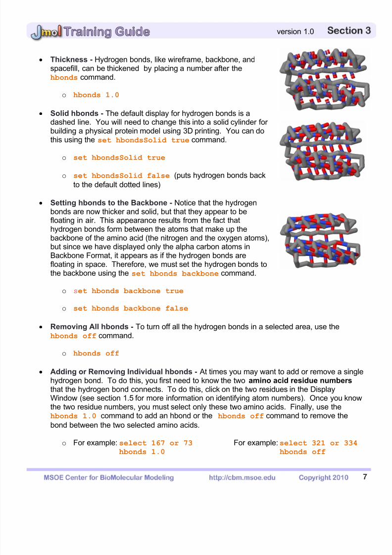
Thickness - Hydrogen bonds, like wireframe, backbone, andspacefill, can be thickened by placing a number after the hbonds command.
o hbonds 1.0
Solid hbonds - The default display for hydrogen bonds is adashed line. You will need to change this into a solid cylinder forbuilding a physical protein model using 3D printing. You can dothis using the set hbondsSolid true command.
o set hbondsSolid true
o set hbondsSolid false (puts hydrogen bonds back
to the default dotted lines)
Setting hbonds to the Backbone - Notice that the hydrogenbonds are now thicker and solid, but that they appear to befloating in air. This appearance results from the fact thathydrogen bonds form between the atoms that make up thebackbone of the amino acid (the nitrogen and the oxygen atoms),but since we have displayed only the alpha carbon atoms inBackbone Format, it appears as if the hydrogen bonds arefloating in space. Therefore, we must set the hydrogen bonds tothe backbone using the set hbonds backbone command.
o set hbonds backbone true
o set hbonds backbone false
Removing All hbonds - To turn off all the hydrogen bonds in a selected area, use thehbonds off command.
o hbonds off
Adding or Removing Individual hbonds - At times you may want to add or remove a singlehydrogen bond. To do this, you first need to know the two amino acid residue numbers
that the hydrogen bond connects. To do this, click on the two residues in the DisplayWindow (see section 1.5 for more information on identifying atom numbers). Once you knowthe two residue numbers, you must select only these two amino acids. Finally, use thehbonds 1.0 command to add an hbond or the hbonds off command to remove the
bond between the two selected amino acids.
o For example: select 167 or 73 For example:select 321 or 334hbonds 1.0 hbonds off
7/25/2019 JMol Training Guide
http://slidepdf.com/reader/full/jmol-training-guide 35/40
8
version 1.0
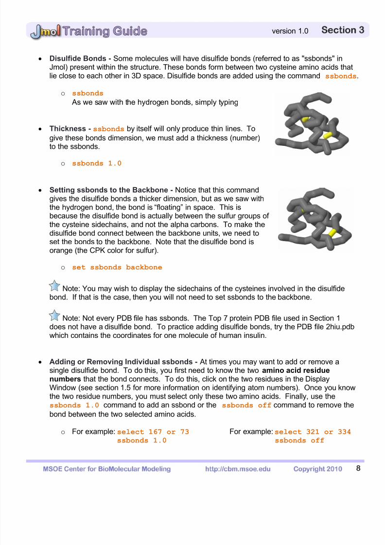
Disulfide Bonds - Some molecules will have disulfide bonds (referred to as "ssbonds" inJmol) present within the structure. These bonds form between two cysteine amino acids thatlie close to each other in 3D space. Disulfide bonds are added using the command ssbonds.
o ssbonds As we saw with the hydrogen bonds, simply typing
Thickness - ssbonds by itself will only produce thin lines. To
give these bonds dimension, we must add a thickness (number)to the ssbonds.
o ssbonds 1.0
Setting ssbonds to the Backbone - Notice that this commandgives the disulfide bonds a thicker dimension, but as we saw withthe hydrogen bond, the bond is “floating” in space. This isbecause the disulfide bond is actually between the sulfur groups ofthe cysteine sidechains, and not the alpha carbons. To make thedisulfide bond connect between the backbone units, we need toset the bonds to the backbone. Note that the disulfide bond isorange (the CPK color for sulfur).
o set ssbonds backbone
Note: You may wish to display the sidechains of the cysteines involved in the disulfidebond. If that is the case, then you will not need to set ssbonds to the backbone.
Note: Not every PDB file has ssbonds. The Top 7 protein PDB file used in Section 1does not have a disulfide bond. To practice adding disulfide bonds, try the PDB file 2hiu.pdbwhich contains the coordinates for one molecule of human insulin.
Adding or Removing Individual ssbonds - At times you may want to add or remove asingle disulfide bond. To do this, you first need to know the two amino acid residue
numbers that the bond connects. To do this, click on the two residues in the DisplayWindow (see section 1.5 for more information on identifying atom numbers). Once you knowthe two residue numbers, you must select only these two amino acids. Finally, use thessbonds 1.0 command to add an ssbond or the ssbonds off command to remove the
bond between the two selected amino acids.
o For example: select 167 or 73 For example:select 321 or 334ssbonds 1.0 ssbonds off
7/25/2019 JMol Training Guide
http://slidepdf.com/reader/full/jmol-training-guide 36/40
9
version 1.0
3.4 - Adding and Removing Support Struts
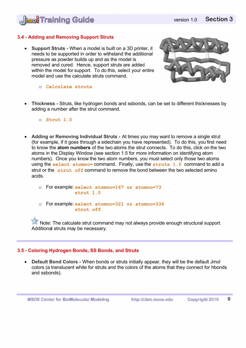
Support Struts - When a model is built on a 3D printer, itneeds to be supported in order to withstand the additional
pressure as powder builds up and as the model isremoved and cured. Hence, support struts are addedwithin the model for support. To do this, select your entiremodel and use the calculate struts command.
o Calculate struts
Thickness - Struts, like hydrogen bonds and ssbonds, can be set to different thicknesses byadding a number after the strut command.
o
Strut 1.0
Adding or Removing Individual Struts - At times you may want to remove a single strut(for example, if it goes through a sidechain you have represented). To do this, you first needto know the atom numbers of the two atoms the strut connects. To do this, click on the twoatoms in the Display Window (see section 1.5 for more information on identifying atomnumbers). Once you know the two atom numbers, you must select only those two atomsusing the select atomno= command. Finally, use the struts 1.0 command to add a
strut or the strut off command to remove the bond between the two selected amino
acids.
o For example: select atomno=167 or atomno=73strut 1.0
o For example: select atomno=321 or atomno=334strut off
Note: The calculate strut command may not always provide enough structural support. Additional struts may be necessary.
3.5 - Coloring Hydrogen Bonds, SS Bonds, and Struts
Default Bond Colors - When bonds or struts initially appear, they will be the default Jmolcolors (a translucent white for struts and the colors of the atoms that they connect for hbondsand ssbonds).
7/25/2019 JMol Training Guide
http://slidepdf.com/reader/full/jmol-training-guide 37/40
1
version 1.0
o If the two atoms the bond is connecting are the same color, then the hbond or ssbondwill be the same color throughout the entire length of the monitor line.
o If the two atoms are different colors, then the hbond or ssbond will be half one colorand half the other color.
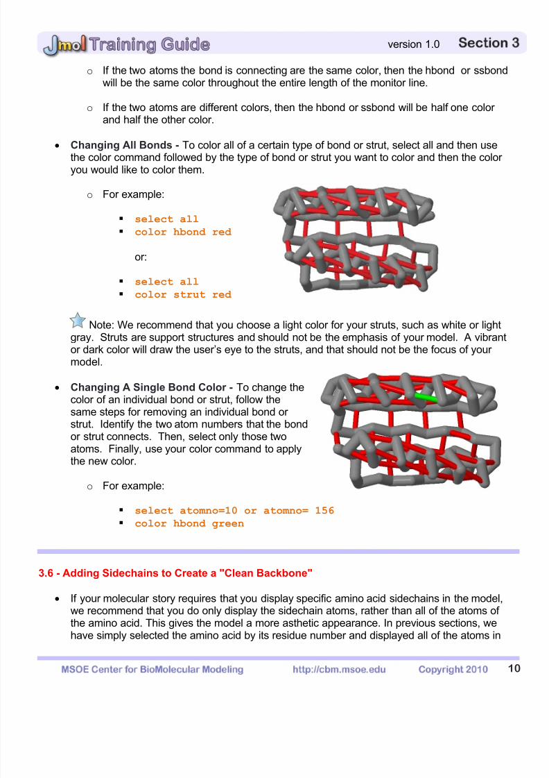
Changing All Bonds - To color all of a certain type of bond or strut, select all and then usethe color command followed by the type of bond or strut you want to color and then the coloryou would like to color them.
o For example:
select all
color hbond red
or:
select all
color strut red
Note: We recommend that you choose a light color for your struts, such as white or lightgray. Struts are support structures and should not be the emphasis of your model. A vibrantor dark color will draw the user’s eye to the struts, and that should not be the focus of yourmodel.
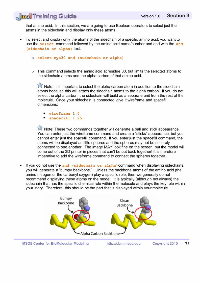
Changing A Single Bond Color - To change thecolor of an individual bond or strut, follow the
same steps for removing an individual bond orstrut. Identify the two atom numbers that the bondor strut connects. Then, select only those twoatoms. Finally, use your color command to applythe new color.
o For example:
select atomno=10 or atomno= 156
color hbond green
3.6 - Adding Sidechains to Create a "Clean Backbone"
If your molecular story requires that you display specific amino acid sidechains in the model,we recommend that you do only display the sidechain atoms, rather than all of the atoms ofthe amino acid. This gives the model a more asthetic appearance. In previous sections, wehave simply selected the amino acid by its residue number and displayed all of the atoms in
7/25/2019 JMol Training Guide
http://slidepdf.com/reader/full/jmol-training-guide 38/40
1
version 1.0
that amino acid. In this section, we are going to use Boolean operators to select just theatoms in the sidechain and display only these atoms.
To select and display only the atoms of the sidechain of a specific amino acid, you want touse the select command followed by the amino acid name/number and end with the and
(sidechain or alpha) text.
o select cys30 and (sidechain or alpha)
o This command selects the amino acid at residue 30, but limits the selected atoms tothe sidechain atoms and the alpha carbon of that amino acid.
Note: It is important to select the alpha carbon atom in addition to the sidechainatoms because this will attach the sidechain atoms to the alpha carbon. If you do notselect the alpha carbon, the sidechain will build as a separate unit from the rest of the
molecule. Once your sidechain is connected, give it wireframe and spacefilldimensions:
wireframe 1.0
spacefill 1.25
Note: These two commands together will generate a ball and stick appearance.You can enter just the wireframe command and create a “sticks” appearance, but youcannot enter just the spacefill command. If you enter just the spacefill command, theatoms will be displayed as little spheres and the spheres may not be securely
connected to one another. The image MAY look fine on the screen, but the model willcome out of the 3D printer in pieces that can’t be put back together! It is thereforeimperative to add the wireframe command to connect the spheres together.
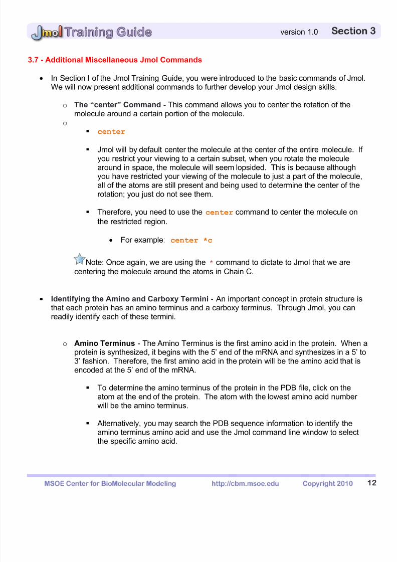
If you do not use the and (sidechain or alpha)command when displaying sidechains,
you will generate a “bumpy backbone.” Unless the backbone atoms of the amino acid (theamino nitrogen or the carbonyl oxygen) play a specific role, then we generally do notrecommend displaying these atoms on the model. It is typically (although not always) thesidechain that has the specific chemical role within the molecule and plays the key role withinyour story. Therefore, this should be the part that is displayed within your molecule.
7/25/2019 JMol Training Guide
http://slidepdf.com/reader/full/jmol-training-guide 39/40
1
version 1.0
3.7 - Additional Miscellaneous Jmol Commands
In Section I of the Jmol Training Guide, you were introduced to the basic commands of Jmol.We will now present additional commands to further develop your Jmol design skills.
o The “center” Command - This command allows you to center the rotation of themolecule around a certain portion of the molecule.
o center
Jmol will by default center the molecule at the center of the entire molecule. Ifyou restrict your viewing to a certain subset, when you rotate the moleculearound in space, the molecule will seem lopsided. This is because althoughyou have restricted your viewing of the molecule to just a part of the molecule,all of the atoms are still present and being used to determine the center of the
rotation; you just do not see them.
Therefore, you need to use the center command to center the molecule on
the restricted region.
For example: center *c
Note: Once again, we are using the * command to dictate to Jmol that we are
centering the molecule around the atoms in Chain C.
Identifying the Amino and Carboxy Termini - An important concept in protein structure isthat each protein has an amino terminus and a carboxy terminus. Through Jmol, you canreadily identify each of these termini.
o Amino Terminus - The Amino Terminus is the first amino acid in the protein. When aprotein is synthesized, it begins with the 5’ end of the mRNA and synthesizes in a 5’ to3’ fashion. Therefore, the first amino acid in the protein will be the amino acid that isencoded at the 5’ end of the mRNA.
To determine the amino terminus of the protein in the PDB file, click on the
atom at the end of the protein. The atom with the lowest amino acid numberwill be the amino terminus.
Alternatively, you may search the PDB sequence information to identify theamino terminus amino acid and use the Jmol command line window to selectthe specific amino acid.

7/25/2019 JMol Training Guide
http://slidepdf.com/reader/full/jmol-training-guide 40/40
version 1.0
o Carboxy Terminus - The Carboxy Terminus, on the other hand, will be the last aminoacid in the protein.
To determine the identity of the carboxy terminus, click on the atom at the endof the protein. The amino acid with the largest number will be the last amino
acid in the protein.
Note: Occasionally a PDB file will have gaps or missing sections in a chainbecause of incomplete experimental data in the file. This can easily beconfused for the Corboxy Terminus. Be sure that you are really looking at thelast amino acid in the chain and not just the beginning of a gap.
Repeating a command - By pressing the up arrow key on the keyboard, the previouscommands that you have entered into the command line window will be repeated.
Undo Button - Near the bottom right of the Console Window is an undo button. This button
can be used to undo recent commands and take your protein design back to a previousstate. Be sure to save your work frequently!
Selecting specific types of atoms - If you wish to select a subset of atoms, such as all ofthe carbon atoms, you can do so by using the select command followed by the type of
atom you would like to select.
o For example: select carbon


![C += [O] CO G ,Jmol](https://static.fdocuments.us/doc/165x107/62730480589fbe3641342ca4/c-o-co-g-jmol.jpg)