JJ306 Autodesk Inventor Week 4 - Project 2 - Assemblies and Constraints
34
ME 24-688 – Week 4 Project 2 – Assemblies and Constraints ME 24-688 – Introduction to CAD/CAE Tools Page 1 of 34 1 Introduction to Assembly Design The following section will give an overview of bring individual components into a common environment and use various tools to assemble them. 1.1 Definition of an Assembly Model You create an assembly by combining multiple components and/or assemblies into a single environment. Parametric relationships are created between each component that determines component behavior in the assembly. These relationships can range from simple constraint-based relationships that determine a component's position in the assembly, to advanced relationships such as adaptivity. Adaptivity enables a component to change size based upon its relationship to other components in the assembly. 1.2 Assembly Constraints You use assembly constraints to create parametric relationships between parts in the assembly. Just as you use 2D constraints to control 2D geometry, you use 3D constraints in an assembly to position parts in relation to other parts. There are four basic assembly constraints, each with unique solutions and options. Mate/Flush Constraint The Mate/Flush constraint is used to align part features such as faces, edges, or axis. ● Before Mate Constraint ● After Mate Constraint ● Before Flush Constraint ● After Flush Constraint
description
JJ306 Autodesk Inventor
Transcript of JJ306 Autodesk Inventor Week 4 - Project 2 - Assemblies and Constraints
ME 24-688 – Week 4
Project 2 – Assemblies and Constraints
ME 24-688 – Introduction to CAD/CAE Tools Page 1 of 34
1 Introduction to Assembly Design
The following section will give an overview of bring individual components into a common environment
and use various tools to assemble them.
1.1 Definition of an Assembly Model
You create an assembly by combining multiple components and/or assemblies into a single environment.
Parametric relationships are created between each component that determines component behavior in
the assembly.
These relationships can range from simple constraint-based relationships that determine a component's
position in the assembly, to advanced relationships such as adaptivity. Adaptivity enables a component to
change size based upon its relationship to other components in the assembly.
1.2 Assembly Constraints
You use assembly constraints to create parametric relationships between parts in the assembly. Just as
you use 2D constraints to control 2D geometry, you use 3D constraints in an assembly to position parts in
relation to other parts. There are four basic assembly constraints, each with unique solutions and options.
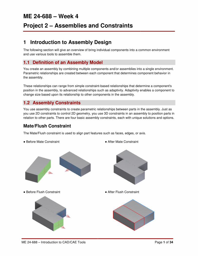
Mate/Flush Constraint
The Mate/Flush constraint is used to align part features such as faces, edges, or axis.
● Before Mate Constraint ● After Mate Constraint
● Before Flush Constraint ● After Flush Constraint

ME 24-688 – Week 4
Project 2 – Assemblies and Constraints
ME 24-688 – Introduction to CAD/CAE Tools Page 2 of 34
Angle Constraint
Used to specify an angle between two parts. The angle constraint is applied to faces, edges, or axes.
● Before Angle Constraint ● After Angle Constraint
Tangent Constraint
Used to define a tangential relationship between two parts. The tangent constraint is generally applied to
circular faces and planar faces. One of the selected faces must be circular.
● Before Tangent Constraint ● After Tangent Constraint
ME 24-688 – Week 4
Project 2 – Assemblies and Constraints
ME 24-688 – Introduction to CAD/CAE Tools Page 3 of 34
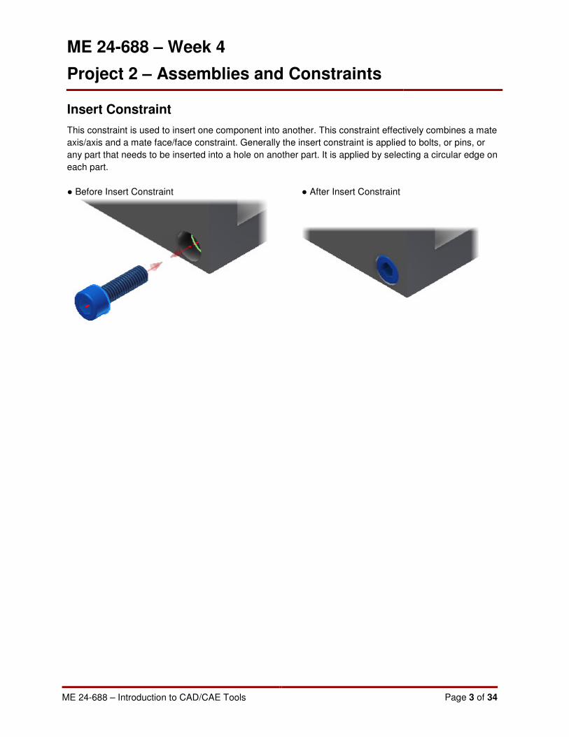
Insert Constraint
This constraint is used to insert one component into another. This constraint effectively combines a mate
axis/axis and a mate face/face constraint. Generally the insert constraint is applied to bolts, or pins, or
any part that needs to be inserted into a hole on another part. It is applied by selecting a circular edge on
each part.
● Before Insert Constraint ● After Insert Constraint

ME 24-688 – Week 4
Project 2 – Assemblies and Constraints
ME 24-688 – Introduction to CAD/CAE Tools Page 4 of 34
2 Robot Arm Assembly
2.1 Project 1
This project will introduce you to placing and assembling parts in Autodesk Inventor 2012. First you will
insert several parts into a new assembly file using several different workflows. Then, using the 3D
constraint tools, you will assemble the parts into a completed assembly.
1. Create a new part using the Standard (mm).iam template.
• On the Quick Access toolbar, click New.
• In the New File dialog box, click the Metric tab.

ME 24-688 – Week 4
Project 2 – Assemblies and Constraints
ME 24-688 – Introduction to CAD/CAE Tools Page 5 of 34
• Select Standard (mm).iam.
• Click OK.
2. On the Quick Access toolbar, click Save to save the assembly.
• In the Save As dialog box, enter Robot-Assembly-A.iam.
• Click Save.
3. Place Component
• Start the Place Component tool
Assemble tab | Component panel | Place Component

ME 24-688 – Week 4
Project 2 – Assemblies and Constraints
ME 24-688 – Introduction to CAD/CAE Tools Page 6 of 34
• In the Place Component dialog box, locate and double-click Robot-Base-Model-A.ipt.
4. Press ESC to cancel the Place Component tool.
• The first occurrence is automatically placed at the assembly origin relative to the
component origin.
• In the browser, notice that the first component is automatically Grounded.
A Grounded component is indicated by the pushpin icon .
Any component can be Grounded or Ungrounded by right-clicking the component and
clicking Grounded from the shortcut menu.
NOTE: Typically only the first component in an assembly is grounded, more than one
grounded component in an assembly can make it difficult to apply 3D constraints
properly.
ME 24-688 – Week 4
Project 2 – Assemblies and Constraints
ME 24-688 – Introduction to CAD/CAE Tools Page 7 of 34
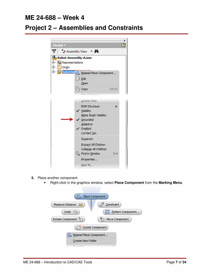
5. Place another component
• Right-click in the graphics window, select Place Component from the Marking Menu
ME 24-688 – Week 4
Project 2 – Assemblies and Constraints
ME 24-688 – Introduction to CAD/CAE Tools Page 8 of 34
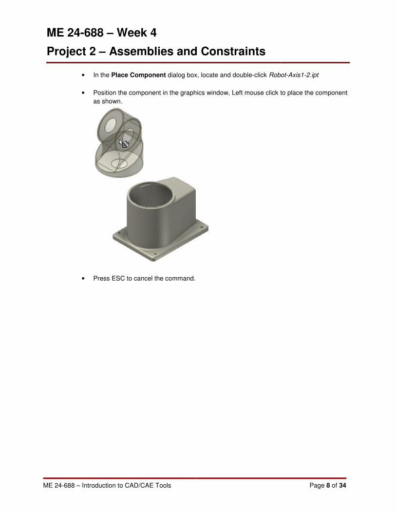
• In the Place Component dialog box, locate and double-click Robot-Axis1-2.ipt
• Position the component in the graphics window, Left mouse click to place the component
as shown.
• Press ESC to cancel the command.
ME 24-688 – Week 4
Project 2 – Assemblies and Constraints
ME 24-688 – Introduction to CAD/CAE Tools Page 9 of 34
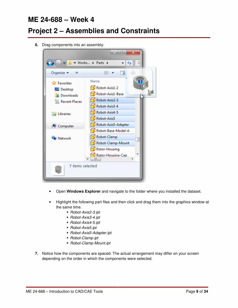
6. Drag components into an assembly:
• Open Windows Explorer and navigate to the folder where you installed the dataset.
• Highlight the following part files and then click and drag them into the graphics window at
the same time.
� Robot-Axis2-3.ipt
� Robot-Axis3-4.ipt
� Robot-Axis4-5.ipt
� Robot-Axis5.ipt
� Robot-Axis5-Adapter.ipt
� Robot-Clamp.ipt
� Robot-Clamp-Mount.ipt
7. Notice how the components are spaced. The actual arrangement may differ on your screen
depending on the order in which the components were selected.

ME 24-688 – Week 4
Project 2 – Assemblies and Constraints
ME 24-688 – Introduction to CAD/CAE Tools Page 10 of 34
8. And 3D Constrains:
• Start the Constrain tool
Assemble tab | Position panel | Constrain
• On the Place Constraint dialog box set the following options
Type: Mate
Solution: Mate

ME 24-688 – Week 4
Project 2 – Assemblies and Constraints
ME 24-688 – Introduction to CAD/CAE Tools Page 11 of 34
• Pick the top surface of component Robot-Base-Model-A for Selection 1
• Pick the bottom surface of component Robot-Axis1-2 for Selection 2
• Enter 0 into the Offset field.
• Click OK to accept the Face/Face Mate constraint

ME 24-688 – Week 4
Project 2 – Assemblies and Constraints
ME 24-688 – Introduction to CAD/CAE Tools Page 12 of 34
9. Click and drag component Robot-Axis1-2
Notice how the part moves around aligned to the top surface of component Robot-Base-Model-A
10. Start the Constrain tool.
• On the Place Constraint dialog box set the following options
Type: Mate
Solution: Mate
• Pick the outer cylindrical surface of component Robot-Base-Model-A for Selection 1
• Pick the outer cylindrical surface of component Robot-Axis1-2 for Selection 2
• Enter 0 into the Offset field.
• Click OK to accept the Axis/Axis Mate constraint
11. Click and drag component Robot-Axis1-2
Notice that now the part only pivots around the previously constrained axis.
• Click Undo from the Quick Access toolbar to revert back to the previous part position.

ME 24-688 – Week 4
Project 2 – Assemblies and Constraints
ME 24-688 – Introduction to CAD/CAE Tools Page 13 of 34
12. Start the Constrain tool.
• On the Place Constraint dialog box set the following options
Type: Angle
Solution: Directed Angle
• Under component Robot-Base-Model-A pick work plane Center-Work Plane for
Selection 1
• Under component Robot-Axis1-2 pick work plane Center-Work Plane for Selection 2
• Enter 0.00 deg into the Angle field.
• Click OK to accept the angle constraint.
13. Click and drag component Robot-Axis1-2
Notice that now the part is fully contained and will not move.
14. Start the Constrain tool.
• On the Place Constraint dialog box set the following options
Type: Mate
Solution: Mate
• Pick the Origin YZ Plane of component Robot-Axis1-2 for Selection 1

ME 24-688 – Week 4
Project 2 – Assemblies and Constraints
ME 24-688 – Introduction to CAD/CAE Tools Page 14 of 34
• Pick the Origin XY Plane of component Robot-Axis2-3 for Selection 2
• Enter 0 into the Offset field.
• Click Apply
NOTE: Clicking Apply accepts the constraint and leaves the command active to apply
additional constraints.
15. Continue the Constrain tool.
• On the Place Constraint dialog box set the following options
Type: Mate
Solution: Mate
• Pick the cylindrical surface shown of component Robot-Axis1-2 for Selection 1
• Pick the cylindrical surface shown of component Robot-Axis2-3 for Selection 2
• Enter 0 into the Offset field.

ME 24-688 – Week 4
Project 2 – Assemblies and Constraints
ME 24-688 – Introduction to CAD/CAE Tools Page 15 of 34
• Click OK
16. Drag component Robot-Axis2-3 to the position shown
17. Start the Constrain tool.
• On the Place Constraint dialog box set the following options
Type: Mate
Solution: Mate
• Pick the Origin XY Plane of component Robot-Axis2-3 for Selection 1
• Pick the Origin XY Plane of component Robot-Axis3-4 for Selection 2
• Enter 0 into the Offset field.
• Click Apply
18. Continue the Constrain tool.
• On the Place Constraint dialog box set the following options
Type: Mate
Solution: Mate
• Pick the cylindrical surface shown of component Robot-Axis2-3 for Selection 1

ME 24-688 – Week 4
Project 2 – Assemblies and Constraints
ME 24-688 – Introduction to CAD/CAE Tools Page 16 of 34
• Pick the cylindrical surface shown of component Robot-Axis3-4 for Selection 2
• Enter 0 into the Offset field.
• Click Apply
19. Drag component Robot-Axis3-4 to change its angle.
• Notice that both Robot-Axis2-3 & Robot-Axis3-4 move.
• Click Undo on the Quick Access toolbar to revert back to the previous position.
20. Ground component
• Right-click component Robot-Axis2-3 in the graphics window.

ME 24-688 – Week 4
Project 2 – Assemblies and Constraints
ME 24-688 – Introduction to CAD/CAE Tools Page 17 of 34
• Click Grounded from the Overflow Menu
21. Drag component Robot-Axis3-4 to position shown to change its angle.
• Notice that only Robot-Axis3-4 moves.
22. Start the Constrain tool.
• On the Place Constraint dialog box set the following options
Type: Angle
Solution: Directed Angle
ME 24-688 – Week 4
Project 2 – Assemblies and Constraints
ME 24-688 – Introduction to CAD/CAE Tools Page 18 of 34
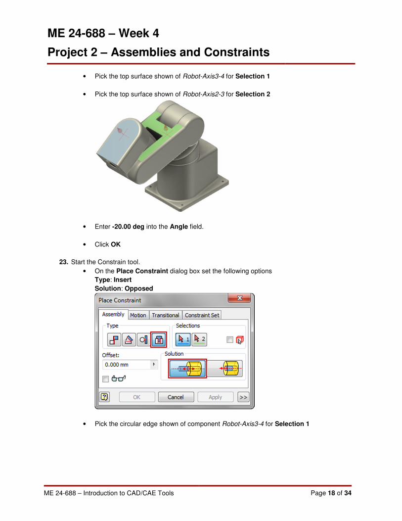
• Pick the top surface shown of Robot-Axis3-4 for Selection 1
• Pick the top surface shown of Robot-Axis2-3 for Selection 2
• Enter -20.00 deg into the Angle field.
• Click OK
23. Start the Constrain tool.
• On the Place Constraint dialog box set the following options
Type: Insert
Solution: Opposed
• Pick the circular edge shown of component Robot-Axis3-4 for Selection 1

ME 24-688 – Week 4
Project 2 – Assemblies and Constraints
ME 24-688 – Introduction to CAD/CAE Tools Page 19 of 34
• Pick the circular edge shown of component Robot-Axis4-5 for Selection 2
• Enter 0 into the Offset field.
• Click Apply
24. Continue the Constrain tool.
• On the Place Constraint dialog box set the following options
Type: Angle
Solution: Directed Angle
• Pick the top surface shown of Robot-Axis4-5 for Selection 1
• Pick the top surface shown of Robot-Axis3-4 for Selection 2
• Enter 0.00 deg into the Angle field.
• Click OK
25. Start the Constrain tool.

ME 24-688 – Week 4
Project 2 – Assemblies and Constraints
ME 24-688 – Introduction to CAD/CAE Tools Page 20 of 34
• On the Place Constraint dialog box set the following options
Type: Insert
Solution: Opposed
• Pick the circular edge shown of component Robot-Axis5 for Selection 1
• Pick the circular edge shown of component Robot-Axis5-Adapter for Selection 2
• Enter 0 into the Offset field.
• Click OK
26. Start the Constrain tool.
• On the Place Constraint dialog box set the following options
Type: Mate
Solution: Mate
• Pick Work Axis1 in component Robot-Axis4-5 for Selection 1
• Pick the Origin Z Axis of component Robot-Axis5 for Selection 2
• Enter 0 into the Offset field.
• Click Apply
27. Continue the Constrain tool.
• On the Place Constraint dialog box set the following options
Type: Mate
Solution: Mate
• Pick Work Plane1 of component Robot-Axis4-5 for Selection 1

ME 24-688 – Week 4
Project 2 – Assemblies and Constraints
ME 24-688 – Introduction to CAD/CAE Tools Page 21 of 34
• Pick XY Plane of component Robot-Axis5 for Selection 2
• Enter 0 into the Offset field.
• Click OK
28. Create subassembly by creating an In-Place Component
• Shift-select both Robot-Clamp and Robot-Clamp-Mount in the graphics window or in the
browser.
• Right-click in the graphics window, select Component from the Overflow Menu

ME 24-688 – Week 4
Project 2 – Assemblies and Constraints
ME 24-688 – Introduction to CAD/CAE Tools Page 22 of 34
• Select Demote from the flyout
• On the Create In-Place Component dialog box enter Robot-GripperAssy for the New
Component Name
• Click the Browse Templates to change the Template to Metric\Standard (mm).iam
• Click OK

ME 24-688 – Week 4
Project 2 – Assemblies and Constraints
ME 24-688 – Introduction to CAD/CAE Tools Page 23 of 34
29. Notice in the browser that both components have been moved into an assembly file.
30. Double click assembly Robot-GripperAssy to edit it within the context of the main assembly.
31. Add a second occurrence of a component
• Right click on component Robot-Clamp
• Select Copy from the Overflow Menu

ME 24-688 – Week 4
Project 2 – Assemblies and Constraints
ME 24-688 – Introduction to CAD/CAE Tools Page 24 of 34
• Right-click the graphics window, select Paste from the Overflow Menu
• The copied component is placed in the assembly.
32. Exit in-context editing
• Click Return from the ribbon
Assemble tab | Return panel | Return
33. Open subassembly
• Right-click subassembly Robot-GripperAssy
• Select Open from the Marking Menu
• Robot-GripperAssy is opened in its own window.
• If the assembly is not visible in the window, use the Zoom All tool from the Navigation
Toolbar
34. Depending on the order in which the components were original placed in Robot-Assembly-A.iam
it may be necessary to change which components are grounded in this new assembly.
Make sure that Robot-Clamp-Mount is grounded and both occurrences of Robot-Clamp are
NOT grounded.

ME 24-688 – Week 4
Project 2 – Assemblies and Constraints
ME 24-688 – Introduction to CAD/CAE Tools Page 25 of 34
35. Start the Constrain tool
• On the Place Constraint dialog box set the following options
Type: Mate
Solution: Flush
• Pick the side face shown of component Robot-Clamp:1 for Selection 1
ME 24-688 – Week 4
Project 2 – Assemblies and Constraints
ME 24-688 – Introduction to CAD/CAE Tools Page 26 of 34
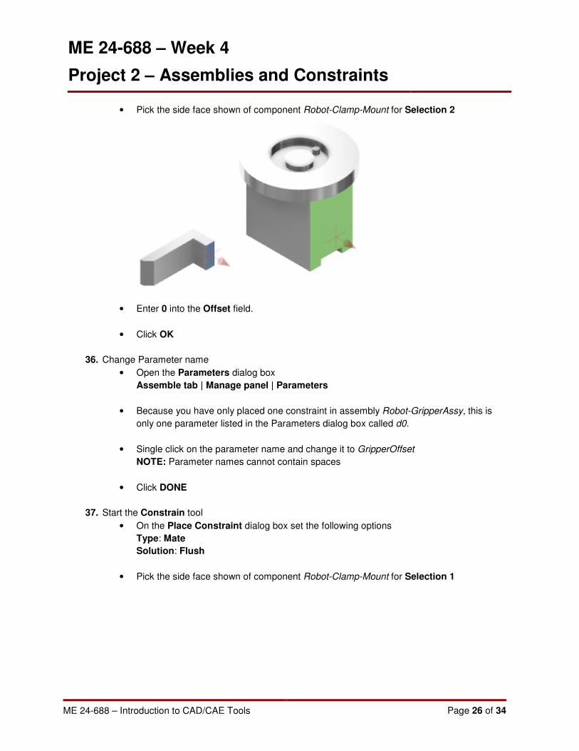
• Pick the side face shown of component Robot-Clamp-Mount for Selection 2
• Enter 0 into the Offset field.
• Click OK
36. Change Parameter name
• Open the Parameters dialog box
Assemble tab | Manage panel | Parameters
• Because you have only placed one constraint in assembly Robot-GripperAssy, this is
only one parameter listed in the Parameters dialog box called d0.
• Single click on the parameter name and change it to GripperOffset
NOTE: Parameter names cannot contain spaces
• Click DONE
37. Start the Constrain tool
• On the Place Constraint dialog box set the following options
Type: Mate
Solution: Flush
• Pick the side face shown of component Robot-Clamp-Mount for Selection 1
ME 24-688 – Week 4
Project 2 – Assemblies and Constraints
ME 24-688 – Introduction to CAD/CAE Tools Page 27 of 34
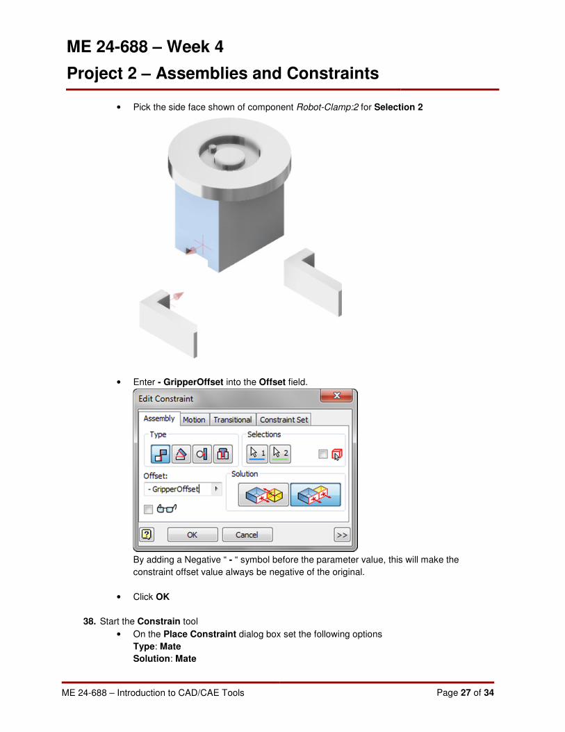
• Pick the side face shown of component Robot-Clamp:2 for Selection 2
• Enter - GripperOffset into the Offset field.
By adding a Negative “ - “ symbol before the parameter value, this will make the
constraint offset value always be negative of the original.
• Click OK
38. Start the Constrain tool
• On the Place Constraint dialog box set the following options
Type: Mate
Solution: Mate
ME 24-688 – Week 4
Project 2 – Assemblies and Constraints
ME 24-688 – Introduction to CAD/CAE Tools Page 28 of 34
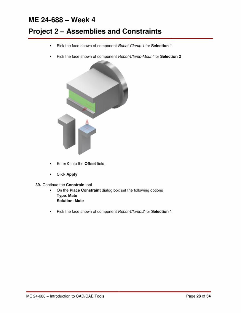
• Pick the face shown of component Robot-Clamp:1 for Selection 1
• Pick the face shown of component Robot-Clamp-Mount for Selection 2
• Enter 0 into the Offset field.
• Click Apply
39. Continue the Constrain tool
• On the Place Constraint dialog box set the following options
Type: Mate
Solution: Mate
• Pick the face shown of component Robot-Clamp:2 for Selection 1

ME 24-688 – Week 4
Project 2 – Assemblies and Constraints
ME 24-688 – Introduction to CAD/CAE Tools Page 29 of 34
• Pick the face shown of component Robot-Clamp-Mount for Selection 2
• Enter 0 into the Offset field.
• Click Apply
40. Continue the Constrain tool
• On the Place Constraint dialog box set the following options
Type: Mate
Solution: Flush
• Pick the face shown of component Robot-Clamp:1 for Selection 1
• Pick the face shown of component Robot-Clamp:2 for Selection 2
• Enter 0 into the Offset field.
ME 24-688 – Week 4
Project 2 – Assemblies and Constraints
ME 24-688 – Introduction to CAD/CAE Tools Page 30 of 34
• Click Apply
41. Continue the Constrain tool
• On the Place Constraint dialog box set the following options
Type: Mate
Solution: Mate
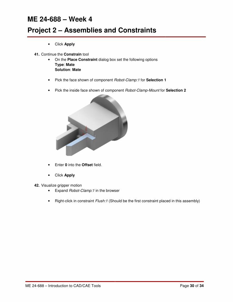
• Pick the face shown of component Robot-Clamp:1 for Selection 1
• Pick the inside face shown of component Robot-Clamp-Mount for Selection 2
• Enter 0 into the Offset field.
• Click Apply
42. Visualize gripper motion
• Expand Robot-Clamp:1 in the browser
• Right-click in constraint Flush:1 (Should be the first constraint placed in this assembly)

ME 24-688 – Week 4
Project 2 – Assemblies and Constraints
ME 24-688 – Introduction to CAD/CAE Tools Page 31 of 34
• Select Drive Constraint from the Shortcut Menu
• On the Drive Constraint dialog box click the expand button

ME 24-688 – Week 4
Project 2 – Assemblies and Constraints
ME 24-688 – Introduction to CAD/CAE Tools Page 32 of 34
• Select Start/End/Start under Repetitions
• Enter 10 in the Repetitions field
• Click the Play button
• Robot-Clamp:1 & Robot-Clamp:2 are animated in the graphics window
Both parts move because Robot-Clamp:2 was contained using the parameter value from
Robot-Clamp:1
43. Click Save on the Quick Access Toolbar
44. Close the window for Robot-GripperAssy.iam
45. Notice that all edits made to Robot-GripperAssy.iam are now shown in Robot-Assembly-A.iam
46. Start the Constrain tool.
• On the Place Constraint dialog box set the following options
Type: Insert
Solution: Opposed
• Pick the circular edge shown of component Robot-GripperAssy for Selection 1

ME 24-688 – Week 4
Project 2 – Assemblies and Constraints
ME 24-688 – Introduction to CAD/CAE Tools Page 33 of 34
• Pick the circular edge shown of component Robot-Axis5-Adapter for Selection 2
• Enter 0 into the Offset field.
• Click Apply
47. Continue the Constrain tool.
• On the Place Constraint dialog box set the following options
Type: Mate
Solution: Mate
• Pick the cylindrical surface shown of component Robot-GripperAssy for Selection 1

ME 24-688 – Week 4
Project 2 – Assemblies and Constraints
ME 24-688 – Introduction to CAD/CAE Tools Page 34 of 34
• Pick the cylindrical surface shown of component Robot-Axis5-Adapter for Selection 2
• Enter 0 into the Offset field.
• Click Apply
48. If you haven’t already done so, Unground component Robot-Axis2-3
49. Click Save on the Quick Access Toolbar
50. Close all files