JJ306 Autodesk Inventor Week 2 - Project 2 - Flange Manifold Part
42
ME 24-688 – Week 2 Project 2 – Flange Manifold Part ME 24-688 – Introduction to CAD/CAE Tools Page 1 of 42 1 Project 2 - Flange Manifold Part 1.1 Instructions This project focuses on additional sketching methods and sketching commands. Revolve and Work features are also introduced. The part being modeled is from machine tooling used in the manufacture of an automobile engine. This flange detail would have several probes attached to it that measure the fluid flow through the flange. The challenge is that the probes need to allow for maximum clearance away from the engine. 1: Create a new part using the Standard (mm).ipt template. ■ On the Quick Access toolbar, click New. ■ In the New File dialog box, click the Metric tab. ■ Select Standard (mm).ipt.
description
JJ306 Autodesk Inventor
Transcript of JJ306 Autodesk Inventor Week 2 - Project 2 - Flange Manifold Part
ME 24-688 – Week 2
Project 2 – Flange Manifold Part
ME 24-688 – Introduction to CAD/CAE Tools Page 1 of 42
1 Project 2 - Flange Manifold Part
1.1 Instructions
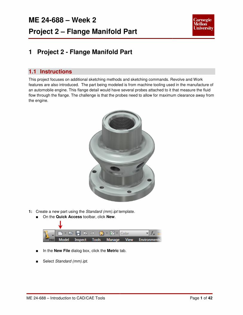
This project focuses on additional sketching methods and sketching commands. Revolve and Work
features are also introduced. The part being modeled is from machine tooling used in the manufacture of
an automobile engine. This flange detail would have several probes attached to it that measure the fluid
flow through the flange. The challenge is that the probes need to allow for maximum clearance away from
the engine.
1: Create a new part using the Standard (mm).ipt template.
■ On the Quick Access toolbar, click New.
■ In the New File dialog box, click the Metric tab.
■ Select Standard (mm).ipt.

ME 24-688 – Week 2
Project 2 – Flange Manifold Part
ME 24-688 – Introduction to CAD/CAE Tools Page 2 of 42
■ Click OK.
2: Create sketch centerline
■ Start the Project Geometry Tool
Sketch Tab | Draw Panel | Project Geometry

ME 24-688 – Week 2
Project 2 – Flange Manifold Part
ME 24-688 – Introduction to CAD/CAE Tools Page 3 of 42
■ In the browser select the Y Axis to project a reference line into sketch.
■ Click Done on the Marking Menu
■ Select the projected reference line in the graphics window and then change it to a centerline by
selecting the Centerline format from the ribbon.
Sketch Tab | Format Panel | Centerline
3: Sketch basic shape
■ Start the Line tool.
In this project you will sketch the approximant profile of the part completely without dimensions,
and then add the required geometric and dimensional constraints to fully constrain the sketch.
■ Scrub over the projected origin point and drag to the right approximately 7 mm.
This will line up you cursor with the origin point.

ME 24-688 – Week 2
Project 2 – Flange Manifold Part
ME 24-688 – Introduction to CAD/CAE Tools Page 4 of 42
Note: The term “Scrub” refers to passing the cursor over geometry in the graphics window
without clicking on it in order to use that geometry in reference to another sketch element being
created. Autodesk Inventor will try to infer what areas to reference, but sometimes you may have
to Scrub over a point or other sketch element before it will be referenced.
A dotted line will show that you are lined up with the point.
■ Left-Click to create the starting point of the first line segment. Drag to the right approximately 17
mm. Click to accept this line segment.
■ Drag up approximately 5 mm. Click to accept this line segment.
ME 24-688 – Week 2
Project 2 – Flange Manifold Part
ME 24-688 – Introduction to CAD/CAE Tools Page 5 of 42
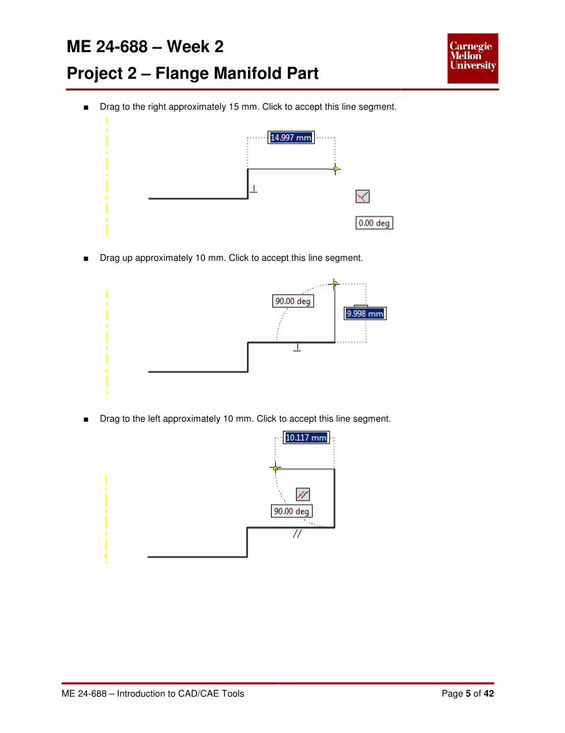
■ Drag to the right approximately 15 mm. Click to accept this line segment.
■ Drag up approximately 10 mm. Click to accept this line segment.
■ Drag to the left approximately 10 mm. Click to accept this line segment.
ME 24-688 – Week 2
Project 2 – Flange Manifold Part
ME 24-688 – Introduction to CAD/CAE Tools Page 6 of 42
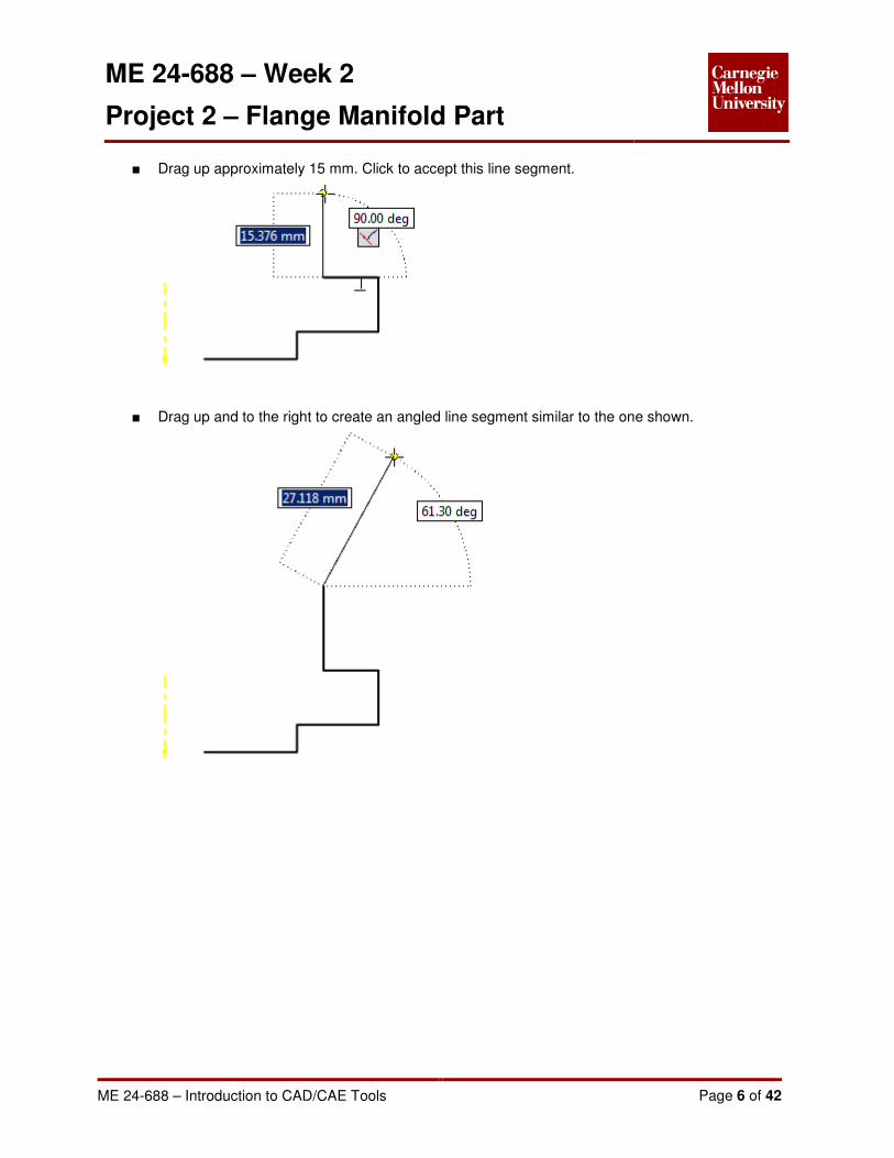
■ Drag up approximately 15 mm. Click to accept this line segment.
■ Drag up and to the right to create an angled line segment similar to the one shown.

ME 24-688 – Week 2
Project 2 – Flange Manifold Part
ME 24-688 – Introduction to CAD/CAE Tools Page 7 of 42
■ Drag up approximately 5 mm. Make sure the Parallel Constraint glyph is shown next to the
cursor to insure this line segment is parallel to the other vertical line segments. Click to accept
this line segment.
■ Drag to the left approximately 15 mm. Click to accept this line segment.
ME 24-688 – Week 2
Project 2 – Flange Manifold Part
ME 24-688 – Introduction to CAD/CAE Tools Page 8 of 42
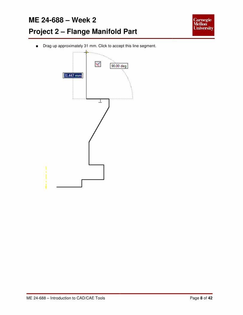
■ Drag up approximately 31 mm. Click to accept this line segment.

ME 24-688 – Week 2
Project 2 – Flange Manifold Part
ME 24-688 – Introduction to CAD/CAE Tools Page 9 of 42
■ Scrub the first starting point to line up this line segment with that point. When the dotted line is
shown, and the line is parallel to the other horizontal lines (Or Perpendicular to the previous line
segment) click to accept.
■ Close the loop by picking the last line segment back to the first start point.

ME 24-688 – Week 2
Project 2 – Flange Manifold Part
ME 24-688 – Introduction to CAD/CAE Tools Page 10 of 42
4: Constrain Sketch
■ Place a Coincident Constraint between the bottom line segment and the projected Origin point.
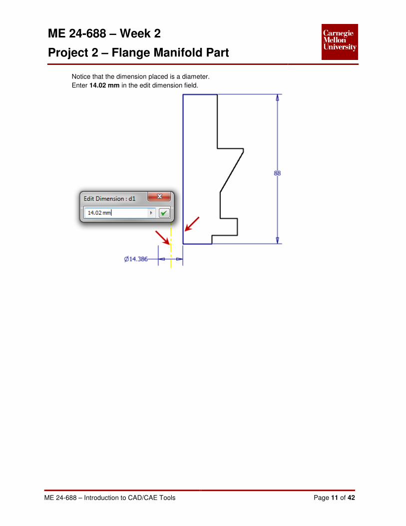
■ Place linear dimensional constraint for the overall part length. Enter 88 mm in the edit dimension
field.
■ Place an inner diameter dimensional constraint.
Using the General Dimension tool from the Sketch tab on the ribbon, select the projected
reference centerline and the inside edge of the part profile.
ME 24-688 – Week 2
Project 2 – Flange Manifold Part
ME 24-688 – Introduction to CAD/CAE Tools Page 11 of 42
Notice that the dimension placed is a diameter.
Enter 14.02 mm in the edit dimension field.

ME 24-688 – Week 2
Project 2 – Flange Manifold Part
ME 24-688 – Introduction to CAD/CAE Tools Page 12 of 42
■ Place the following diameter dimensional constraints.

ME 24-688 – Week 2
Project 2 – Flange Manifold Part
ME 24-688 – Introduction to CAD/CAE Tools Page 13 of 42
■ Place the following linear dimensional constraints.

ME 24-688 – Week 2
Project 2 – Flange Manifold Part
ME 24-688 – Introduction to CAD/CAE Tools Page 14 of 42
■ Place an angular dimensional constraint.
Using the General Dimension tool from the Sketch tab on the ribbon, select the angled line
segment and a vertical line segment. Enter 30 in the edit dimension field.
■ The sketch profile is now fully constrained.
■ Exit the sketch.
5: Revolve Base Feature.
■ Start the Revolve Tool
Model Tab | Create Panel | Revolve

ME 24-688 – Week 2
Project 2 – Flange Manifold Part
ME 24-688 – Introduction to CAD/CAE Tools Page 15 of 42
Because there is only one closed loop exists in the sketch, the sketch profile is automatically
selected
Click OK
6: Using the Viewing tools reposition the view as shown.

ME 24-688 – Week 2
Project 2 – Flange Manifold Part
ME 24-688 – Introduction to CAD/CAE Tools Page 16 of 42
7: Change Part Color
■ On the Quick Access Toolbar pick Zinc from the part color drop down list.
ME 24-688 – Week 2
Project 2 – Flange Manifold Part
ME 24-688 – Introduction to CAD/CAE Tools Page 17 of 42
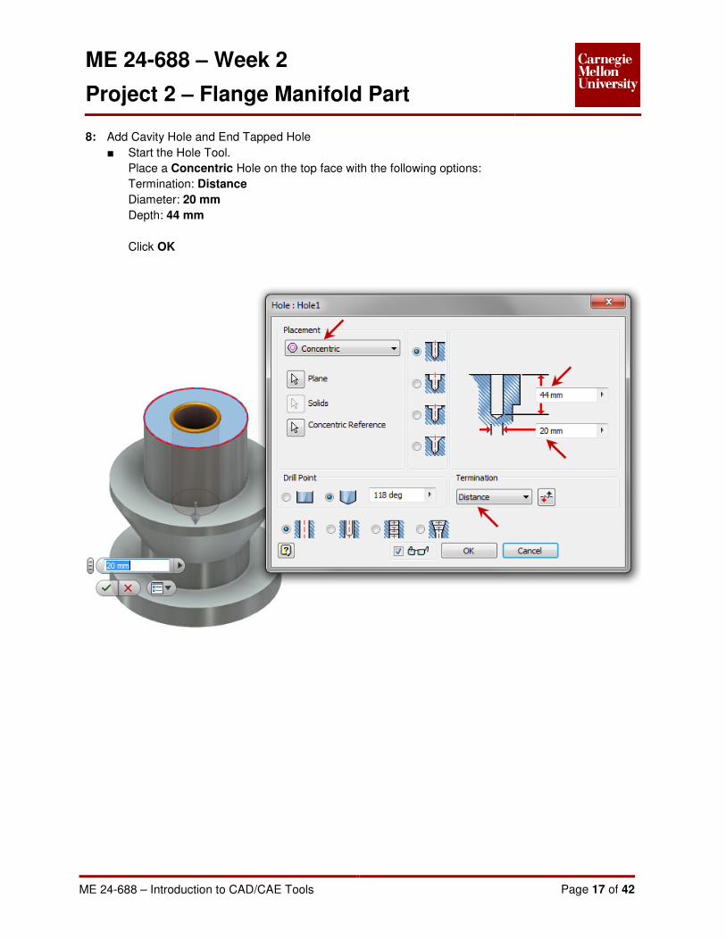
8: Add Cavity Hole and End Tapped Hole
■ Start the Hole Tool.
Place a Concentric Hole on the top face with the following options:
Termination: Distance
Diameter: 20 mm
Depth: 44 mm
Click OK

ME 24-688 – Week 2
Project 2 – Flange Manifold Part
ME 24-688 – Introduction to CAD/CAE Tools Page 18 of 42
■ Start Hole Tool
Place a Concentric Hole on the top face with the following options:
Type: Tapped Hole
Thread Type: ANSI Metric M Profile
Size: 30
Designation: M30x2
Termination: Distance
Depth: 21 mm
Full Depth
Click OK

ME 24-688 – Week 2
Project 2 – Flange Manifold Part
ME 24-688 – Introduction to CAD/CAE Tools Page 19 of 42
9: Add Extrusion Cut
■ Start a new sketch on the top surface
■ Start the Center Point Circle Tool
Sketch Tab | Draw Panel | Circle
Pick the projected center point for the Center Point Circle starting point.
Drag away from the center. Enter 38 mm in the direct entry field. Press Tab to lock in the value.
Press ENTER to accept the circle.
ME 24-688 – Week 2
Project 2 – Flange Manifold Part
ME 24-688 – Introduction to CAD/CAE Tools Page 20 of 42
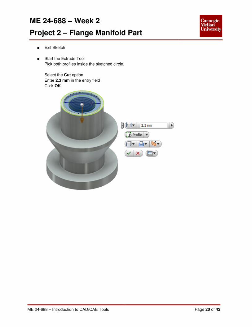
■ Exit Sketch
■ Start the Extrude Tool
Pick both profiles inside the sketched circle.
Select the Cut option
Enter 2.3 mm in the entry field
Click OK

ME 24-688 – Week 2
Project 2 – Flange Manifold Part
ME 24-688 – Introduction to CAD/CAE Tools Page 21 of 42
10: Add bolt pattern
■ Create Sketch on bottom face shown.
■ Start the Line Tool
Draw vertical line starting from the center point 31.5 mm long
■ Exit the Sketch
■ Start Hole Tool
Place a From Sketch Hole picking the line endpoint in the sketch with following options:
Type: Tapped Hole
Thread Type: ANSI Metric M Profile
Size: 6
Designation: M6x1

ME 24-688 – Week 2
Project 2 – Flange Manifold Part
ME 24-688 – Introduction to CAD/CAE Tools Page 22 of 42
Termination: To
Pick the top surface of the bottom flange area for the “To” termination surface
Full Depth
Click OK
■ Start the Circular Pattern tool
Model Tab | Pattern Panel | Circular
ME 24-688 – Week 2
Project 2 – Flange Manifold Part
ME 24-688 – Introduction to CAD/CAE Tools Page 23 of 42
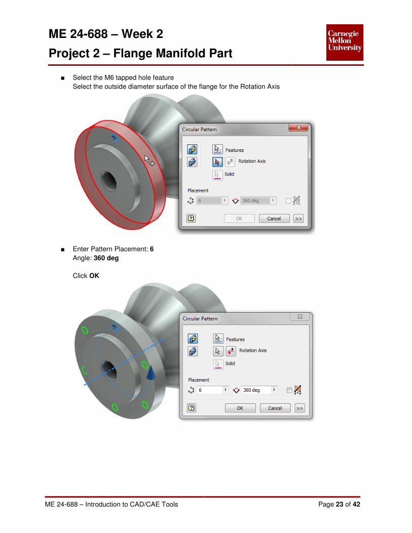
■ Select the M6 tapped hole feature
Select the outside diameter surface of the flange for the Rotation Axis
■ Enter Pattern Placement: 6
Angle: 360 deg
Click OK
ME 24-688 – Week 2
Project 2 – Flange Manifold Part
ME 24-688 – Introduction to CAD/CAE Tools Page 24 of 42
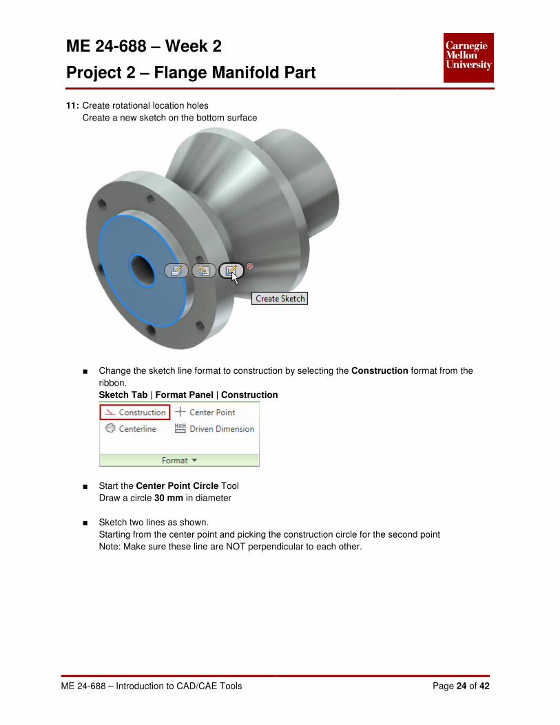
11: Create rotational location holes
Create a new sketch on the bottom surface
■ Change the sketch line format to construction by selecting the Construction format from the
ribbon.
Sketch Tab | Format Panel | Construction
■ Start the Center Point Circle Tool
Draw a circle 30 mm in diameter
■ Sketch two lines as shown.
Starting from the center point and picking the construction circle for the second point
Note: Make sure these line are NOT perpendicular to each other.

ME 24-688 – Week 2
Project 2 – Flange Manifold Part
ME 24-688 – Introduction to CAD/CAE Tools Page 25 of 42
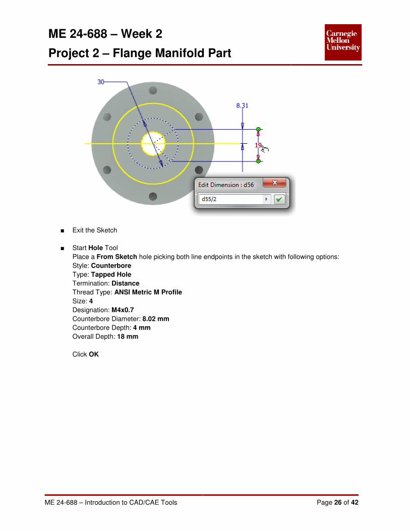
■ Place a dimensional constraint between the line endpoints.
Enter 19 mm into the edit dimension field
■ Place a dimensional constraint between the upper line endpoint and the projected XY Plane.
▪ With the Edit Dimension field active, click on the 19 mm dimension.
The dimension reference will be displayed in the Edit Dimension field (For this example it is
shown as d55, it will be different for you)
▪ Create an equation by adding a forward slash “/” (for divide) and a “2
▪ Click OK
▪ The value of this dimensional constraint will now be half the distance between the two line
endpoints.
ME 24-688 – Week 2
Project 2 – Flange Manifold Part
ME 24-688 – Introduction to CAD/CAE Tools Page 26 of 42
■ Exit the Sketch
■ Start Hole Tool
Place a From Sketch hole picking both line endpoints in the sketch with following options:
Style: Counterbore
Type: Tapped Hole
Termination: Distance
Thread Type: ANSI Metric M Profile
Size: 4
Designation: M4x0.7
Counterbore Diameter: 8.02 mm
Counterbore Depth: 4 mm
Overall Depth: 18 mm
Click OK

ME 24-688 – Week 2
Project 2 – Flange Manifold Part
ME 24-688 – Introduction to CAD/CAE Tools Page 27 of 42
12: Reposition the view as shown

ME 24-688 – Week 2
Project 2 – Flange Manifold Part
ME 24-688 – Introduction to CAD/CAE Tools Page 28 of 42
13: Create a Work Plane
■ Start the Work Plane tool
Model Tab | Work Features Panel | Plane
■ In the browser click the Z Axis for the first reference
Pick the YZ Plane for the second reference
■ Drag the direct manipulation arrow back until the work plane is shown at -30.00 deg
Click OK
14: Create an Offset Work Plane
■ First you need to get a measurement for the offset.
Click the model and click Edit Sketch to activate the first profile sketch you created.

ME 24-688 – Week 2
Project 2 – Flange Manifold Part
ME 24-688 – Introduction to CAD/CAE Tools Page 29 of 42

ME 24-688 – Week 2
Project 2 – Flange Manifold Part
ME 24-688 – Introduction to CAD/CAE Tools Page 30 of 42
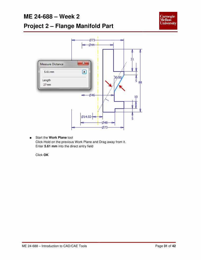
■ Draw a construction line parallel to the angled line in the sketch
■ Start the Measure Distance tool
Tools Tab | Measure Panel | Distance
Click on the original angled line and the new construction line to get the measurement between
them. A distance of 5.61 mm is shown in the Measure Distance dialog box.
Copy this dimension for use in the next step.
Exit the sketch.
ME 24-688 – Week 2
Project 2 – Flange Manifold Part
ME 24-688 – Introduction to CAD/CAE Tools Page 31 of 42
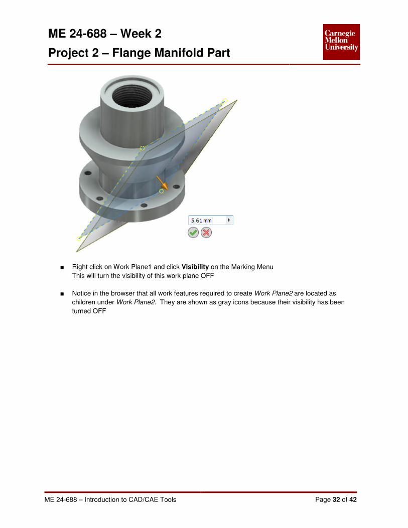
■ Start the Work Plane tool
Click-Hold on the previous Work Plane and Drag away from it.
Enter 5.61 mm into the direct entry field
Click OK
ME 24-688 – Week 2
Project 2 – Flange Manifold Part
ME 24-688 – Introduction to CAD/CAE Tools Page 32 of 42
■ Right click on Work Plane1 and click Visibility on the Marking Menu
This will turn the visibility of this work plane OFF
■ Notice in the browser that all work features required to create Work Plane2 are located as
children under Work Plane2. They are shown as gray icons because their visibility has been
turned OFF

ME 24-688 – Week 2
Project 2 – Flange Manifold Part
ME 24-688 – Introduction to CAD/CAE Tools Page 33 of 42
15: Create Manifold Hole Pattern On Round Angled Surface
■ Create a new sketch on Work Plane2
■ Start the Point tool
Sketch Tab | Draw Panel | Point
Place a Point approximately -51 mm directly above the project Origin point

ME 24-688 – Week 2
Project 2 – Flange Manifold Part
ME 24-688 – Introduction to CAD/CAE Tools Page 34 of 42
■ Place a Vertical constraint between the drawn point and the projected Origin point

ME 24-688 – Week 2
Project 2 – Flange Manifold Part
ME 24-688 – Introduction to CAD/CAE Tools Page 35 of 42
■ Place a dimensional constraint of 51 mm between the two points
■ Exit Sketch
■ Start Hole Tool
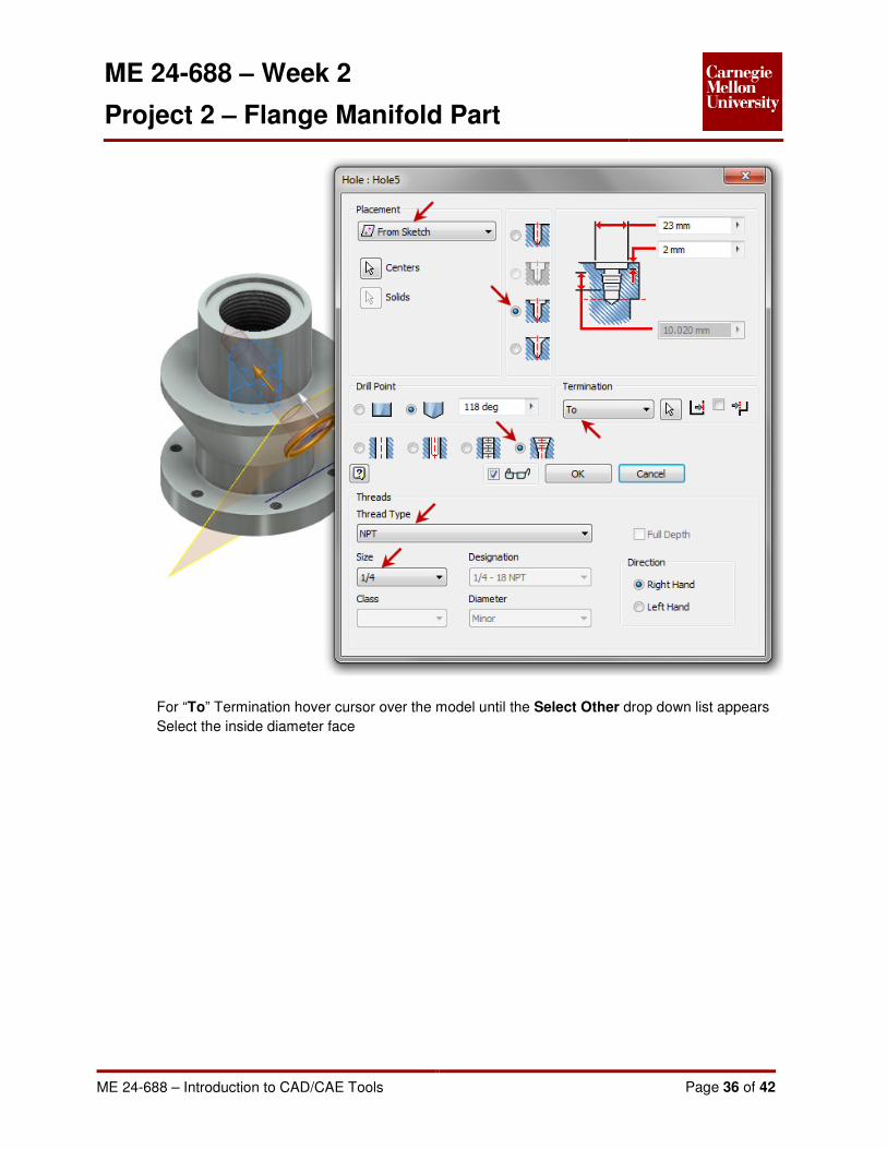
Place a From Sketch hole picking both line endpoints in the sketch with following options:
Style: Countersink
Type: Taper Tapped Hole
Termination: To
Thread Type: NPT
Size: 1/4
Countersink Diameter: 23 mm
Countersink Depth: 2 mm
ME 24-688 – Week 2
Project 2 – Flange Manifold Part
ME 24-688 – Introduction to CAD/CAE Tools Page 36 of 42
For “To” Termination hover cursor over the model until the Select Other drop down list appears
Select the inside diameter face

ME 24-688 – Week 2
Project 2 – Flange Manifold Part
ME 24-688 – Introduction to CAD/CAE Tools Page 37 of 42
■ Click OK
■ Start the Circular Pattern tool
Select the 1/4 NPT tapped hole feature
Select the outside diameter surface of the flange for the Rotation Axis
Enter Pattern Placement: 6
Angle: 360 deg

ME 24-688 – Week 2
Project 2 – Flange Manifold Part
ME 24-688 – Introduction to CAD/CAE Tools Page 38 of 42
Click OK
16: Apply Chamfers
■ Start the Chamfer tool
Model Tab | Modify Panel | Chamfer
■ Select the top edge
Enter Distance: 1.5 mm into the Mini-Tool Bar
Click Apply
■ Change Chamfer style to Distance and Angle
Select top surface adjacent to the tapped hole and top edge of the tapped hole
Enter Distance: 1.5 mm and Angle: 60 deg
Click Apply

ME 24-688 – Week 2
Project 2 – Flange Manifold Part
ME 24-688 – Introduction to CAD/CAE Tools Page 39 of 42
■ Change Chamfer style to Distance
Select top surface of bottom flange
Enter Distance: 2 mm
Click Apply
■ Select the two bottom edges shown
Enter Distance: 0.5 mm
Click OK to accept and exit the Chamfer tool

ME 24-688 – Week 2
Project 2 – Flange Manifold Part
ME 24-688 – Introduction to CAD/CAE Tools Page 40 of 42
17: Apply Fillets
■ Start the Fillet tool
Model Tab | Modify Panel | Fillet
■ Select edge as shown
Enter Radius: 4 mm into the Mini-Tool Bar
Click Apply

ME 24-688 – Week 2
Project 2 – Flange Manifold Part
ME 24-688 – Introduction to CAD/CAE Tools Page 41 of 42
■ Add Fillet Set
▪ Select edge as shown
Enter Radius: 8 mm into the Mini-Tool Bar
▪ Click Add Constant Fillet Radius Set
▪ Select edge as shown
Enter Radius: 3 mm into the Mini-Tool Bar
▪ Notice that both the 8mm and 3mm radiuses are created as one Fillet feature in the browser.

ME 24-688 – Week 2
Project 2 – Flange Manifold Part
ME 24-688 – Introduction to CAD/CAE Tools Page 42 of 42
18: Save Part
■ On the Quick Access toolbar, click Save.
■ In the Save As dialog box, enter file name FlangeManifold.ipt
■ Click Save