Philosophy of Building CN2 China Telecom Corporation Xu Jianfeng.

Jianfeng Liu, Jaehan Jeon, Mi-Suk Hong, KyungTae Do, HyoSig Won, JungYun Choi, Kee Sup Kim
System LSI Division Samsung Electronics Co., Ltd.

• The evolution of smart phones and tablet has ever driven the continuous improvement of computing and communication capability of mobile SoCs
• Sophisticated low power design technologies have been applied in the mobile SoC designs, which require a unified power specification to manage the integration complexity across all the design and verification steps
Internet
Map/Nav
Social Network
O/S
Complex HW
MultiMedia
Game & Cam
Adaptive Body Bias
Smart Power Control
DVFS
Power Gating
Multi-VDD
Clock Gating
Low Power CTS
Multi-Vth
High-K Metal Gate
SOI
1

• UPF 1.0 was standardized by Accellera, later revised into IEEE 1801-2009. IEEE 1801-2013 is on the way to release later this year
• We have used UPF 1.0 with bottom-up hierarchy design flow
• EDA tools have been more stable for UPF 1.0 support, which is very important for product design
• Bottom-up hierarchy flow is the only feasible approach in the era of billion gate SoC design
• Each block has its own UPF file Easy to manage and reuse UPF file
TOP UPF
Block RTL
DC (Block-Level)
DC (Top Level)
Block ILM
ICC (Block-Level)
ICC (TOP-Level) Top-level
Netlist+UPF’
TOP RTL Block ILM
Full Chip
Netlist+UPF”
Block UPF Block UPF Block UPF
Block
Netlist+UPF’
2

• There are many challenges in deploying UPF hierarchy flow in SoCs • A single power specification is used in multiple tools and steps in design and verification flow. A small
change in UPF may incur significant TAT overhead in SoC design schedule
• The complicated interactions between library, design, UPF and EDA tools makes the debug process
difficult
• The huge complexity of billion gate SoC, the complex low power techniques, special design styles of
SoCs and the bottom-up hierarchy flow put significant challenges in UPF deployment
EDA Tools
UPF
the UPF file becomes too big to manage in billion gate SoC era
3
The complexity of power state table (PST) increase almost exponential with the number of power domains
Some RTL coding styles are difficult or not compatible with UPF flow
Custom design styles requires special attention in UPF flow

• Library PVT Corners • In UPF flow, voltages values should be matched between liberty, synopsys tools script and
UPF
• Liberty library (.db/.lib) for all the PVT corners needed for SoC design should be available
• The library physical (FRAM) views should match liberty library (.db) • Update FRAM when mismatch happens
- Icc_shell> update_mw_port_by_db –db “mem.db” –mw_lib mem.mw
# liberty library voltage_map (VDDP, 2.97000); voltage_map (VDDI, 0.9)
# synopsys tool scripts set_voltage 2.97 –object {VDD_IO_A} set_voltage 0.9 –object {VDD_CORE}
# UPF add_port_state VDD_IO_A –state {bst_IO_ON 2.97} add_port_state VDD_CORE –state {bst_CORE_ON 0.9}
VDDP VDDI …
cell
VDD_IO_A
VDD_CORE
domain
Liberty (pg_pin)
UPF (create supply
port, net)
DC (mapping supply name
& value )
4

Top
Macro
• UPF compliant libraries should be available for not only standard cells (SC) and power management cells (PMK), but also memories and Macros
• There isn’t any strict UPF compliance checker for Macro libraries. • Communication between library design and SoC designer is important to make UPF
compliant library
5
VDD_TOP: 1.65V VDD_M: 1.9V
Case B: the related supply net of an input
Pin of a Macro is wrong, causing level shifter
insertion
Update the library for correct “related_supply_net” attribute
Case A: An power port in a Macro was
initially defined as a signal port in libraries,
which caused warning in UPF flow
After discussion, the port is corrected as power port in library
Top
Macro IP
VDD_TOP
VSS VSS
VDD_O
A
VDDM DVDD

• It is utterly important to write UPF correctly in the early phase, to avoid design turnover and save project turn-around-time.
• Power net should be declared for all the design elements inside its power domain, not only for the existed design elements, but also for newly inserted power management cells by UPF and the buffers and physical cells in all the implementation stages
• This rule also applies when connecting power to logic 1 tie
• Isolation strategy:
• If a power domain boundary pin is driven by a constant, the clamp value of isolation cells should align
to the constant at the domain boundary
• Isolation is not need for floating power domain outputs
• Make a default rule when writing isolation policy, for possible stitch signals added by DFT or P&R tools
• For MCMM flow, it is mandatory to add worst, nominal, best voltage conditions in UPF with add_port_state command
• Eg. add_port_state VDD –state {VDD_wst 0.95} –state {VDD_nom 1.0} -state {VDD_bst 1.05}
6
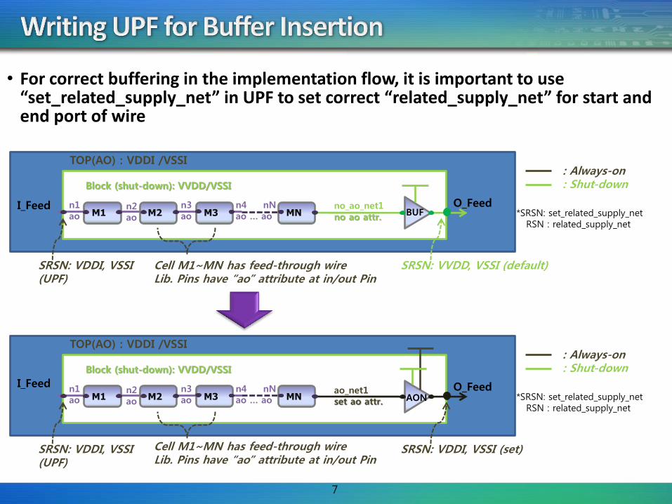
• For correct buffering in the implementation flow, it is important to use “set_related_supply_net” in UPF to set correct “related_supply_net” for start and end port of wire
M1 M2 M3 MN
Block (shut-down): VVDD/VSSI
n1 ao
n2 ao
n3 ao
n4 nN ao … ao
no_ao_net1 no ao attr.
O_Feed
TOP(AO) : VDDI /VSSI
SRSN: VDDI, VSSI (UPF)
Cell M1~MN has feed-through wire Lib. Pins have “ao” attribute at in/out Pin
SRSN: VVDD, VSSI (default)
: Always-on : Shut-down
*SRSN: set_related_supply_net RSN : related_supply_net
BUF
M1 M2 M3 MN
Block (shut-down): VVDD/VSSI
n1 ao
n2 ao
n3 ao
n4 nN ao … ao
ao_net1 set ao attr.
O_Feed
TOP(AO) : VDDI /VSSI
SRSN: VDDI, VSSI (UPF)
SRSN: VDDI, VSSI (set)
: Always-on : Shut-down
*SRSN: set_related_supply_net RSN : related_supply_net
AON
7
Cell M1~MN has feed-through wire Lib. Pins have “ao” attribute at in/out Pin
I_Feed
I_Feed

• Special attention needs to be paid when writing UPF for bottom-up hierarchy flow
• For the control signals of isolation/power-switch/retention cells in UPF, ILM boundary pins should be used in hierarchy flow
• For bottom-up hierarchy flow, a separate UPF file is needed to specify the isolation strategy for parent location • If isolation location is parent, then isolation cells will be placed outside a block. Therefore,
the isolation control signal is not accessible inside the block • This isolation strategy should be prepared as a separate file, for top-level implementation
Top
Block The isolation control signal is out-of-scope inside block
ISO
8
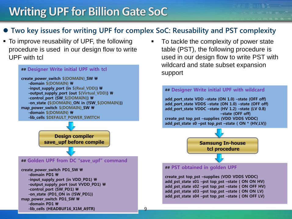
To improve reusability of UPF, the following
procedure is used in our design flow to write
UPF with tcl
## Designer Write initial UPF with tcl
create_power_switch ${DOMAIN}_SW \ -domain ${DOMAIN} \ -input_supply_port {in ${Real_VDD}} \ -output_supply_port {out ${Virtual_VDD}} \ -control_port {SW_${DOMAIN}} \ -on_state {${DOMAIN}_ON in {!SW_${DOMAIN}}} map_power_switch ${DOMAIN}_SW \ -domain ${DOMAIN} \ -lib_cells $DEFAULT_POWER_SWITCH
Design compiler save_upf before compile
9
## Golden UPF from DC “save_upf” command
create_power_switch PD1_SW \ -domain PD1 \ -input_supply_port {in VDD_PD1} \ -output_supply_port {out VVDD_PD1} \ -control_port {SW_PD1} \ -on_state {PD1_ON in {!SW_PD1}} map_power_switch PD1_SW \ -domain PD1 \ -lib_cells {HEADBUF16_X1M_A9TR}
To tackle the complexity of power state
table (PST), the following procedure is
used in our design flow to write PST with
wildcard and state subset expansion
support
Two key issues for writing UPF for complex SoC: Reusability and PST complexity
## Designer Write initial UPF with wildcard
add_port_state VDD –state {ON 1.0} –state {OFF off} add_port_state VDDS –state {ON 1.0} –state {OFF off} add_port_state VDDC –state {HV 1.2} –state {LV 0.8} –state {OFF off} create_pst top_pst –supplies {VDD VDDS VDDC} add_pst_state s0 –pst top_pst –state { ON * {HV,LV}}
Samsung In-house tcl procedure
## PST obtained in golden UPF
create_pst top_pst –supplies {VDD VDDS VDDC} add_pst_state s01 –pst top_pst –state { ON ON HV} add_pst_state s02 –pst top_pst –state { ON OFF HV} add_pst_state s03 –pst top_pst –state { ON ON LV} add_pst_state s04 –pst top_pst –state { ON OFF LV}

• While UPF flow makes low power flow integration more fluent, it brings several limitations for implementing low power techniques in SoCs. • In UPF flow, Isolation cells and level shifters can only added at power domain boundary
• UPF support for modeling low power scheme inside Macros is limited
• UPF support for modeling top level power constraints to block level is limited
• To overcome these constraints, the SoC design has to be modified.
10
• RTL modification for inserting isolation cells for Macro input
A wrapper is created to add isolation cells
Top
Macro
ISO
Top
Macro Wrapper
Macro
ISO

• Example: When the output of one power domain is multi-fanout signals, which drives different power domains, it is difficult to describe this situation in UPF.
11
Top
Block A
ISO
Block B
Block C
ISO
ISO Top
Block A
ISO
Block B
Block C
ISO
• Assume that Block A, B, C are defined as defined as different power domains, which can power ON/OFF independently. TOP can only be power OFF when all the block A, B and C are OFF
Case A: RTL modification is not needed. User can define isolation policy as inputs for block B and C
Case B: This case need RTL change, i.e. duplicate the multi-fanout at block A for driving TOP domain

Case A: A macro has internal footer switch, while SoC uses header switch
• Problem: EDA tool can not treat correctly for the
isolation requirement between Macro and SoC,
and a lot of warning messages were issued
• Work-Around: “set_related_supply_net” was used
to solve this temporally
• EDA tool has been enhanced to solve this for the derivative products
VDD
VSS
VSSI
SLEEPN
DIN Internal Logic
DOUT
12
Case B: Some IO libraries are wide-range IO, which can be used with different voltage connections
Problem: EDA tool treat this case as operation condition violation, and tool crashes happens
Work-Around: Duplicate library temporally
EDA tool has been enhanced: voltage value in UPF can override the operation condition specified in IO liberty library
Top
PWR_PAD (PAD_B) 1.65V
IP_B (3.0V)
PAD AY
VDD_TOP: 3.0V
Due to high complexity of the UPF development in hierarchy designs, EDA vendors’
tight support and collaboration is valuable

• The recipes summarized in this presentation are based on the experience of successful deployment of the UPF flow in several Samsung SoC tapouts
• The major benefits obtained from UPF deployment • Build the accurate power specification for complex SoC designs • Minimize the integration efforts of low power design flow for derivative products • Align the low power specification across implementation and verification flow
• Pending issues in UPF flow • DK release generally has a fixed version for a specific technology node. However, A lot of
new features in UPF flow are only available in new library compiler version, which make it difficult to maintain DK release.
• To avoid TAT issue, a detailed guide and ECO-like flow is needed when UPF has to be changed at later P&R stages
13

• UPF has provided several advantages for seamless low power flow integration. However, it brings significant challenges in practical design flow as well.
• In this presentation, we outlined the details of challenging issues of UPF deployment in hierarchy implementation flow, such as the impact of UPF update on TAT, the complicated interaction between design, UPF, library and EDA tools, the increased UPF file size and complex power state table etc.
• We have shared our know-how to overcome these challenges. We presented our methodology in four aspects: making correct library release, guideline to write UPF, how to adapt the design to UPF flow and recent collaborations with EDA vendors on tool enhancement.
• The UPF methodology summarized in this presentation has helped us to deploy the UPF hierarchy flow successfully in several Samsung SoC tapeouts
14