Jett8 9V-JEB uncontained engine failure - FINAL … 9V-JEB Report (2013-09-26).pdf · FINAL REPORT...
28
FINAL REPORT BOEING 747-200F, REGISTRATION 9V-JEB UNCONTAINED ENGINE FAILURE 17 DECEMBER 2009 AIB/AAI/CAS.062 Air Accident Investigation Bureau of Singapore Ministry of Transport Singapore 26 September 2013
Transcript of Jett8 9V-JEB uncontained engine failure - FINAL … 9V-JEB Report (2013-09-26).pdf · FINAL REPORT...

FINAL REPORT
BOEING 747-200F, REGISTRATION 9V-JEB UNCONTAINED ENGINE FAILURE
17 DECEMBER 2009
AIB/AAI/CAS.062
Air Accident Investigation Bureau of Singapore Ministry of Transport
Singapore
26 September 2013

1 © 2013 Government of Singapore
The Air Accident Investigation Bureau of Singapore
The Air Accident Investigation Bureau (AAIB) is the air accidents and incidents investigation authority in Singapore responsible to the Ministry of Transport. Its mission is to promote aviation safety through the conduct of independent and objective investigations into air accidents and incidents.
The AAIB conducts the investigations in accordance with the Singapore Air Navigation (Investigation of Accidents and Incidents) Order 2003 and Annex 13 to the Convention on International Civil Aviation, which governs how member States of the International Civil Aviation Organization (ICAO) conduct aircraft accident investigations internationally.
In carrying out the investigations, the AAIB will adhere to ICAO’s stated objective, which is as follows:
“The sole objective of the investigation of an accident or incident shall be the prevention of accidents and incidents. It is not the purpose of this activity to apportion blame or liability.”
Accordingly, it is inappropriate that AAIB reports should be used to assign fault or blame or determine liability, since neither the investigation nor the reporting process has been undertaken for that purpose.

2 © 2013 Government of Singapore
CONTENTS
Page SYNOPSIS 3 AIRCRAFT DETAILS 3 GLOSSARY OF ABBREVIATIONS 4 1 FACTUAL INFORMATION 5 1.1 History of the flight 5 1.2 Damage to aircraft 5 1.3 Personnel information 13 1.4 Aircraft information 13 1.5 Flight recorders 13 1.6 Tests and research 14 1.7 Organisation and management information 15 1.8 Additional information 15 2 ANALYSIS 21 2.1 Engine failure 21 2.2
2.3 2.4
S9 HPC/S1 HPT blade failures Engine health monitoring Safety information from engine manufacturer
21 21 22
3 CONCLUSION 24 3.1 Findings 24 4 SAFETY ACTIONS 25 5 SAFETY RECOMMENDATIONS 27

3 © 2013 Government of Singapore
SYNOPSIS
At about 1135 hours on 17 December 2009, an uncontained failure of the No.4 engine occurred to a Boeing 747 freighter aircraft at about 7,000 ft after departure from Singapore Changi Airport. The engine was shut down and the aircraft returned to Changi Airport and landed safely. There was no injury to any person in this incident. Examination of the engine revealed that the stage 3 low pressure turbine (LPT) rotor and all blade sections aft of the stage 3 LPT rotor were missing. In addition, the exhaust core nozzle and exhaust centre body were also missing.
The occurrence was classified as a serious incident by the Air Accident Investigation Bureau of Singapore. The uncontained engine failure was a result of the circumferential fracture of the stage 3 LPT disk forward spacer arm. The stage 3 LPT failure is consistent with the engine having sustained vibration due to HP rotor imbalance. AIRCRAFT DETAILS Aircraft type : Boeing 747-200F Operator : Jett8 Airlines Cargo Registration : 9V-JEB Number and Type of Engines : 4 x General Electric CF6-50E2 Type of Flight : Scheduled cargo flight Persons on Board : Six

4 © 2013 Government of Singapore
GLOSSARY OF ABBREVIATIONS
AD Airworthiness Directive ADD Aircraft deferred defect AOW All Operator Wire APU Auxiliary power unit ATC BSI
Air traffic control Borescope inspection
CAAS Civil Aviation Authority of Singapore CSN Cycles since new CVR Cockpit voice recorder EGT Exhaust gas temperature EHM Engine health monitoring FAA FDR
U.S. Federal Aviation Administration Flight data recorder
FE FF FO
Flight Engineer Fuel flow First Officer
FPI Fluorescent penetrant inspection HCF High cycle fatigue HP HPC HPT
High pressure High pressure compressor High pressure turbine
LE LP
Leading edge Low pressure
LPT Low pressure turbine NGV NTSB OGV
Nozzle guide vanes U.S. National Transportation Safety Board Outlet guide vanes
PF Pilot flying PIC Pilot-in-command S1, S2, … Stage 1, stage 2, … SB Service Bulletin TE Trailing edge TSN Time since new

5 © 2013 Government of Singapore
1 FACTUAL INFORMATION All times used in this report are Singapore times. Singapore time is
eight hours ahead of Coordinated Universal Time (UTC). 1.1 History of the flight
1.1.1 At about 1130 hours on 17 December 2009, a Boeing freighter
aircraft (registration 9V-JEB) took off from Runway 02C of Singapore Changi Airport for Hong Kong. The flight crew consisted of a Pilot-in-command (PIC), a First Officer (FO) and a Flight Engineer (FE). The FO was the pilot flying (PF).
1.1.2 The auxiliary power unit (APU) was unserviceable and the engine start-up was done using a ground power unit. Prior to departure, the crew did not notice any engine abnormality.
1.1.3 After take-off, the aircraft was cleared to 24,000 ft by the air traffic
control (ATC). At about 1135 hours, as the aircraft was transiting through 7,000 ft, the crew heard a muffled ‘bang’ and detected the smell of burning oil in the cockpit. There was no fire warning. According to the FE, the oil pressure and quantity of the No.4 engine were reducing rapidly following the bang. The low pressure rotor speed (N1) and high pressure rotor speed (N2) had also dropped significantly but did not drop to zero. There was no exceedance of exhaust gas temperature (EGT). The engine was subsequently shut down.
1.1.4 After informing ATC of the engine problem, the PIC took over the
control of the aircraft. The crew performed the engine failure checklist procedure and requested to return to Changi Airport. The aircraft landed uneventfully on Runway 02C. There was no injury to any person in this incident.
1.1.5 Post-flight inspection revealed that the No.4 engine had an
uncontained engine failure. There was no evidence of fire. 1.2 Damage to aircraft
1.2.1 Fan 1.2.1.1 The S1 fan blades of the fan module of the No.4 engine, the S1 fan
shroud, the fan outer guide vanes (OGV) and booster assembly inlet showed no damage and there was no evidence of foreign object damage (FOD).

6 © 2013 Government of Singapore
1.2.2 Low pressure turbine (LPT) 1.2.2.1 The stage 3 (S3) LPT nozzle guide vane (NGV) section of the No.4
engine was exposed, and the S3 LPT rotor and all blade sections aft of the S3 LPT rotor were missing. In addition, the exhaust cone and the exhaust were also missing (see Figures 1, 2 and 3).
Figure 1. Engine components found missing (highlighted in green)
Figure 2. Side view of the damaged No.4 engine (upper picture with
missing engine component) and the typical view of an undamaged engine (lower picture)

7 © 2013 Government of Singapore
Figure 3. Rear view of the damaged turbine section
1.2.2.2 The S3 LPT disk forward spacer arm was separated
circumferentially 360° at the intersection of the spacer arm and the S3 LPT disk forward flange (see Figure 4).
Figure 4. Separation of S3 LPT disk
FWD

8 © 2013 Government of Singapore
1.2.2.3 The S1 LPT and the S2 LPT blades showed blade tip shrouds rub wear that was consistent with stator case outer shroud rubbing.
1.2.2.4 Multiple turbine blades debris fragments were recovered from both
halves of the engine cowls. There were multiple damages on the No.4 pylon structure; one puncture on the bulk cargo door and one puncture on the right side of the vertical stabiliser (see Figures 5, 6 and 7). There were also multiple minor dents and punctures on the lower surface of the right hand wing. An under-wing fuel tank access panel inboard of No.4 engine was also punctured resulting in some fuel leakage.
Figure 5. Damage on the No.4 pylon, fuel tank access panel and the lower
wing surfaces
Figure 6. Damage on bulk cargo door

9 © 2013 Government of Singapore
Figure 7. Damage on vertical stabiliser 1.2.3 High pressure compressor (HPC)
1.2.3.1 The HPC airfoils exhibited minor tip curl and burrs from S1 through
S8, consistent with stator casing rubbing. One S9 HPC blade was found with a large airfoil portion missing from about 1 inch from the blade platform (see Figure 8). Two S10 HPC blades were also found with half of their airfoil missing. There were signs of heavy impact damage on many of the blades of S10 to S14 HPC.
1.2.3.2 The damage to the S10 to S14 blades was assessed to be a
consequence of the impact with the airfoil debris from the broken S9 HPC blade. The remainder of the S9 HPC blade with a large airfoil missing was sent for metallurgical examination, which revealed that the S9 HPC blade had fractured from the leading edge area and that the fracture had propagated with features consistent with high cycle fatigue (HCF). The fracture origin area was found to have been damaged and it was not possible to determine exactly how the fracture had originated. There is no evidence of any foreign material at the fracture origin area.

10 © 2013 Government of Singapore
Figure 8. S9 HPC blade showing fracture origin area and direction
of fracture propagation (indicated by blue arrow) 1.2.4 High pressure turbine (HPT) 1.2.4.1 Two of the S1 HPT blades (marked ‘X’ and ‘Y’ in Figure 9) were
found with more than 50% airfoil loss. These two blades were not adjacent to each other and were in fact separated by three undamaged blades. For the blade marked ‘X’, the airfoil loss was from blade tip to mid-section. For the blade marked ‘Y’, the airfoil loss was along the trailing edge area. The damage to these two blades did not appear to have arisen from impact as otherwise the three blades that were in between would almost certainly be damaged as well.
Figure 9. Two broken S1 HPT blades (marked ‘X’ and ‘Y’) with more than 50% airfoil loss
X
Y
Z
Direction of fracture
propagation (blue arrow)
Close-up view of fracture
origin area (indicated by the
green box)

11 © 2013 Government of Singapore
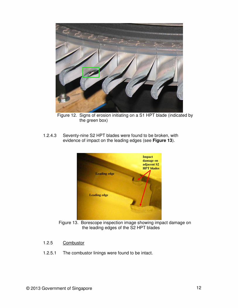
1.2.4.2 The S1 HPT blade (marked ‘Z’ in Figure 9) that was adjacent to blade X sustained damage on the trailing edge area. Thirteen of the S1 HPT blades were found damaged with nicks, oxidation or cracks (see Figure 10). The rest of the S1 HPT blades appeared to be normal (see Figure 11), although erosion consistent with normal wear-and-tear had started on some blades (see Figure 12).
Figure 10. Some of the thirteen S1 high pressure turbine (HPT) blades
found damaged with nicks, oxidation or cracks
Figure 11. No signs of damage on the rest of the S1 HPT blade
12 © 2013 Government of Singapore
Figure 12. Signs of erosion initiating on a S1 HPT blade (indicated by
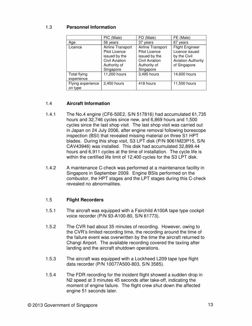
the green box) 1.2.4.3 Seventy-nine S2 HPT blades were found to be broken, with
evidence of impact on the leading edges (see Figure 13).
Figure 13. Borescope inspection image showing impact damage on
the leading edges of the S2 HPT blades 1.2.5 Combustor 1.2.5.1 The combustor linings were found to be intact.
Leading edge
Impact
damage on
adjacent S2
HPT blades
Leading edge
13 © 2013 Government of Singapore
1.3 Personnel Information
PIC (Male) FO (Male) FE (Male)
Age 56 years 37 years 67 years
Licence Airline Transport Pilot Licence issued by the Civil Aviation Authority of Singapore
Airline Transport Pilot Licence issued by the Civil Aviation Authority of Singapore
Flight Engineer Licence issued by the Civil Aviation Authority of Singapore
Total flying experience
11,200 hours 3,495 hours 14,600 hours
Flying experience on type
2,450 hours 418 hours 11,500 hours
1.4 Aircraft Information 1.4.1 The No.4 engine (CF6-50E2, S/N 517816) had accumulated 61,735
hours and 32,746 cycles since new, and 6,869 hours and 1,500 cycles since the last shop visit. The last shop visit was carried out in Japan on 24 July 2006, after engine removal following borescope inspection (BSI) that revealed missing material on three S1 HPT blades. During this shop visit, S3 LPT disk (P/N 9061M23P15, S/N CAV43946) was installed. This disk had accumulated 32,899.44 hours and 6,911 cycles at the time of installation. The cycle life is within the certified life limit of 12,400 cycles for the S3 LPT disk.
1.4.2 A maintenance C-check was performed at a maintenance facility in
Singapore in September 2009. Engine BSIs performed on the combustor, the HPT stages and the LPT stages during this C-check revealed no abnormalities.
1.5 Flight Recorders 1.5.1 The aircraft was equipped with a Fairchild A100A tape type cockpit
voice recorder (P/N 93-A100-80, S/N 61773). 1.5.2 The CVR had about 35 minutes of recording. However, owing to
the CVR’s limited recording time, the recording around the time of the failure event was overwritten by the time the aircraft returned to Changi Airport. The available recording covered the taxiing after landing and the aircraft shutdown operations.
1.5.3 The aircraft was equipped with a Lockheed L209 tape type flight
data recorder (P/N 10077A500-803, S/N 3585).
1.5.4 The FDR recording for the incident flight showed a sudden drop in N2 speed at 3 minutes 45 seconds after take-off, indicating the moment of engine failure. The flight crew shut down the affected engine 51 seconds later.
14 © 2013 Government of Singapore
1.6 Test and Research 1.6.1 The AAIB conducted a teardown of the No.4 engine in an engine
overhaul facility in Istanbul, Turkey. The teardown was witnessed by representatives from the U.S. National Transportation Safety Board (NTSB) and the engine manufacturer.
1.6.2 Metallurgical analysis of the S3 LPT disk fracture surfaces showed
that multiple high-cycle, high-amplitude fatigue (HAF) cracks had initiated around the forward spacer arm. The cracks linked together, forming a circumferential crack that resulted in the separation of the disk.
1.6.3 The key findings from the engine teardown are:
(a) Visual examination of the two S1 HPT blades found with
missing airfoil material (referred to in paragraph 1.2.4.1) showed evidence of erosion on the damaged airfoil surface, which is typical of engine operation. The damages on the 13 S1 HPT blades (referred to in paragraph 1.2.4.2) and the S2 HPT blades (referred to in paragraph 1.2.4.3) were likely caused by impact with the debris pieces of the two S1 HPT blades.
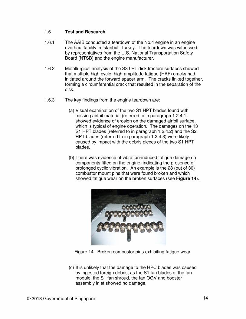
(b) There was evidence of vibration-induced fatigue damage on
components fitted on the engine, indicating the presence of prolonged cyclic vibration. An example is the 28 (out of 30) combustor mount pins that were found broken and which showed fatigue wear on the broken surfaces (see Figure 14).
Figure 14. Broken combustor pins exhibiting fatigue wear
(c) It is unlikely that the damage to the HPC blades was caused by ingested foreign debris, as the S1 fan blades of the fan module, the S1 fan shroud, the fan OGV and booster assembly inlet showed no damage.

15 © 2013 Government of Singapore
(d) It is unlikely that any debris had transited from the HPC through the combustor to the HPT, as the combustor linings were found to be intact.
1.7 Organisational and management information 1.7.1 The operator was operating only one aircraft (i.e. the occurrence
aircraft 9V-JEB). Before the occurrence, the aircraft had been operating, on average, two to three medium-haul chartered flights a day.
1.7.2 Line maintenance in Singapore was provided by a maintenance
service provider. The operator also had a contractor to provide engine health monitoring (EHM) service.
1.7.3 Aircraft engineering matters were handled by the operator’s
Engineering Department. This department was responsible for coordinating with the line maintenance service provider and the EHM contractor and would evaluate their maintenance action recommendations.
1.7.4 The operator conducted weekly operational meetings with its line
maintenance service provider and the EHM contractor to discuss outstanding aircraft engineering matters and recommendations (engine related issues would be one of the topics discussed). The last meeting before the 17 December 2009 occurrence was conducted on 11 December 2009.
1.7.5 The operator did not have any spare engine. It would source for engine replacement through its maintenance service provider based in Hong Kong or Germany.
1.8 Additional information No.4 engine technical log observations 1.8.1 There were five technical log entries of EGT abnormalities during
the period from 14 November to 9 December 2009. The first three instances (on 14, 15 and 17 November 2009) were assessed by the operator as indication defects and were rectified by a change of indicators.
1.8.2 The fourth instance (on 8 December 2009) was addressed by the
operator as an indication defect. A check on the No.4 engine EGT harness was performed and a swap of the No.1 and No.4 engines’ EGT indicators was carried out.
1.8.3 In the fifth instance (on 9 December 2009), the EGT readings were observed to be fluctuating widely during cruise. The indicator

16 © 2013 Government of Singapore
connectors were inspected and cleaned on 9 December 2009, and there were no further technical log report of EGT reading fluctuations.
Engine manufacturer Service Bulletin 1.8.4 The engine manufacturer issued Service Bulletin (SB) 72-1307 on
25 November 2009 to recommend to CF6-50 operators to borescope inspect the S1 and S2 HPT blades for missing material within 200 cycles from the date of issuance of the SB, with a view to preventing uncontained failure of the S3 LPT disk assembly. The SB was prompted by two uncontained S3 LPT disk failure events that occurred on 4 July 2008 and 26 March 2009 (see paragraph 1.8.16 (a) and (b)).
Engine health monitoring 1.8.5 The EHM programme aimed to detect engine deterioration at an
early stage so as to allow for corrective action before safe operation is affected. Maintenance shop visits could also be better timed and maintenance costs reduced.
1.8.6 The EHM contractor would provide the operator with weekly engine
trend analysis reports, highlighting outstanding issues and offering maintenance action recommendations. The EHM contractor based its analysis on data provided by the operator. Such data were manually collected by flight crews during flights1.
1.8.7 On 19 November 2009, the EHM contractor informed the operator, through its EHM report, that an EGT spike was detected, and requested the operator for additional engine data. The operator provided the data accordingly.
1.8.8 On 24 November 2009, the EHM contractor informed the operator
that the EGT shift at that time was not accompanied by an increase in fuel flow and this was no longer a high priority item. The EHM contractor recommended that the operator schedule an EGT indication system check2 at a convenient maintenance opportunity and advise its findings. At the weekly operational meeting on 26 November 2009, the operator planned to conduct the No.4 EGT indication system check in mid-December 2009.
1.8.9 On 26 November 2009, the EHM contractor informed the operator,
through its EHM report, of an upward shift in EGT which was still
1 Data (engine and aircraft parameters) were collected only during stabilised cruise phase. No data
were collected during unstable flight conditions due to weather or other external factors. 2 An EGT indication system check would entail checking at least the EGT gauge, EGT thermocouple
harness and probes.

17 © 2013 Government of Singapore
being monitored. The EHM contractor recommended that the operator perform a No.4 EGT indication system check.
1.8.10 Subsequently, the EHM contractor observed an increase in No. 4
engine fuel flow (FF) and EGT. It recommended to the operator on three occasions (on 3, 5 and 10 December 2009) to conduct a BSI in addition to the No.4 EGT indication system check. The recommended BSI was for S1 and S12 HPC blades and S1 and S2 HPT blades. In their email correspondences with the operator, the EHM contractor highlighted that the BSI should be done as a priority over the EGT indication system check, and that it should be done quickly.
1.8.11 Around 5 December 2009, the operator’s line maintenance service
provider began to arrange for the EGT indication system check and BSI. These were tentatively scheduled to be carried out in Hong Kong on 9 December 2009.
1.8.12 The operator had to reschedule the BSI to 13 December 2009 as
the aircraft did not have enough ground time in Hong Kong. Then the operator postponed further the BSI to the aircraft’s next maintenance A-check scheduled on 28 December 2009. Its considerations were: (a) The operator believed that the abnormal No.4 engine FF and
EGT trends were due to an EGT indication fault, in view of past history of EGT indicator faults which had been resolved through maintenance actions (see paragraphs 1.8.1-1.8.3).
(b) There were no abnormal flight crew reports after 9 December
2009. (c) SB 72-1307 recommended (see paragraph 1.8.4) a BSI of the
S1 and S2 HPT blades for missing material within 200 cycles from the date of issuance of the SB (i.e. 25 November 2009). No.4 engine had operated substantially fewer than 200 cycles since 25 November 2009.
1.8.13 Aware of the operator’s decision to delay the BSI to the aircraft’s
next maintenance A-check on 28 December 2009, the EHM contractor reiterated to the operator about its recommendation for an EGT indication system check and a BSI of the S1 and S12 HPC blades and S1 and S2 HPT blades. The EHM contractor explained that the deteriorating engine trends were likely to be genuine, whereas an EGT indication fault which the operator had suspected would not have produced such observations. The operator’s line maintenance service contractor concurred with the EHM contractor’s recommendation for engine borescope. However, the operator did not take up the recommendation and the operator has no record of the considerations leading to this decision.

18 © 2013 Government of Singapore
1.8.14 Chart 1 shows the time history of the observed EGT trends of the four engines of the aircraft and the EHM recommendations.
Chart 1 1.8.15 After the occurrence, the operator told the investigation team that
the BSI was only a recommendation and therefore there was no urgency to act on the recommendation.
Similar engine failure occurrences 1.8.16 To date the US NTSB has identified six other similar occurrences
(none of which had resulted in injury or fatality). These are as follows:
(a) On 4 July 2008, a Boeing B747-300 experienced an engine (CF6-50) failure during initial climb after take-off from Jeddah, the Kingdom of Saudi Arabia. The NTSB investigated this occurrence and determined the probable cause to be the failure of the LPT S3 disk due to a design that is vulnerable to HPT
Chart 1 shows EGT trends for 9V-JEB’s four engines:
a – (19 November 2009) First observation of EGT spike for the No.4 engine
b – (26 November 2009) EGT uptrend confirmed with recommendation for an EGT indication check
c – (3 December 2009) Continued upward shift of EGT, recommendation given for an EGT indication check
and a BSI of the HP section
d – (10 December 2009) Continued upward shift of EGT, another recommendation given for the EGT
indication check and the BSI of the HP section
e – (17 December 2009) Failure event
EGT/N1
6.5
6.6
6.7
6.8
6.9
7
7.1
7.2
7.3
7.4
7.5
7.6
10/24/09
0:00
11/3/09
0:00
11/13/09
0:00
11/23/09
0:00
12/3/09
0:00
12/13/09
0:00
12/23/09
0:00
Time
EG
T/N
1
ENG #1
ENG #2
ENG #3
ENG #4
a b c d e
EGT graph for No.4
engine showing
upward trend
EG
T/N
1 (
ºC p
er
unit N
1 s
peed)
Date
19 © 2013 Government of Singapore
unbalance-induced synchronous vibration that cannot be detected in flight, and the subsequent uncontained engine failure.
(b) On 26 March 2009, a McDonnell Douglas DC-10F experienced a loss of oil pressure in one engine (CF6-50) about 30 minutes after take-off from Manaus, Brazil. The crew shut down the engine and diverted to Medellin, Columbia. The NTSB also investigated this occurrence and concluded with the same probable cause as for the occurrence mentioned in sub-paragraph (a) above.
(c) On 10 April 2010, an Airbus A300B4 experienced an engine (CF6-50) failure while accelerating for take-off at Manama, Bahrain. The crew rejected the take-off, activated the fire suppression system, and evacuated the aircraft. The Turkish Directorate General of Civil Aviation is investigating this occurrence.
(d) On 26 May 2010, an Airbus A300 experienced an uncontained
engine (CF6-50) failure in Istanbul, Turkey, resulting in an aborted take-off. The Turkish Directorate General of Civil Aviation is investigating this occurrence.
(e) On 17 July 2010, a Boeing B747-200 experienced an
uncontained engine (CF6-50) failure in Cairo, Egypt, resulting in an aborted take-off. The Egyptian Ministry of Civil Aviation is investigating this occurrence.
(f) On 24 September 2010, a Boeing 747-200 experienced an
uncontained engine (CF6-50) failure in Frankfurt, Germany, resulting in an aborted take-off. The German Federal Bureau of Aircraft Accidents Investigation is investigating this occurrence.
1.8.17 The S3 LPT disk failures on 4 July 2008 and 26 March 2009 had
been attributed by the engine manufacturer to high cycle fatigue, a result of the vibration transferred from the HPT. This vibration was caused by rotor imbalance due to airfoil material loss from the HPT blades. However, it is to be noted that even with no airfoil material loss of the HPT blades, vibration could still happen, owing, for example, to severely out-of-balance HP rotor, as was found by the engine manufacturer to be the case with the 10 April 2010 and 26 May 2010 occurrences.
1.8.18 In its All Operator Wire (AOW) 10/CF6/017 to all CF6-50 operators
on 27 July 2010, the engine manufacturer mentioned that two of the S3 LPT disk failure engines with high HPT imbalance did not exhibit HPT blade distress as noted in other event engines, and that the lack of HPT blade distress in these engines meant that BSI would not have been successful in identifying these two engines as having possible HP rotor imbalance and/or vibration.

20 © 2013 Government of Singapore
1.8.19 The engine manufacturer introduced SB 72-1313 on 9 August 2010
(see paragraph 4.2.1) to recommend a one-time vibration check of all CF6-50 engines to assess if there was any abnormal engine vibration due to HP rotor operation.
1.8.20 According to the engine manufacturer, from 1973 to 1990, there
were seven shop findings of cracks in the CF6-503 S3 LPT disk forward spacer arm. After the 6th shop finding, the engine manufacturer introduced SB 72-961 in August 1989 to require shot peening to the disk. There were no further crack findings after 1990, until 2006 when three additional shop findings of S3 LPT cracks were detected before the first on-wing occurrence on 4 July 2008.
Dissemination of safety information by engine manufacturer 1.8.21 Immediately after the 4 July 2008 and 26 March 2009 occurrences,
the engine manufacturer informed all operators about these occurrences through its AOW distribution system (AOW 08/CF6/017 and AOW 09/CF6/015 respectively). According to the operator, it did not receive the AOWs.
1.8.22 The engine manufacturer also organised a fleet-wide WebEx
meeting with all operators on 12 September 2009 to discuss the introduction of SB 72-1307, which required BSI of S1 and S2 HPT blades. According to the operator, it did not receive the information on the WebEx meeting.
1.8.23 The investigation team understood from the engine manufacturer
that it is not the engine manufacturer’s practice to ascertain if the operators received such information as AOWs and the convening of WebEx meetings.
1.8.24 The investigation team found that the operator did not update the
engine manufacturer on changes to the names and contact details of the persons within the operator’s organisation responsible for liaising with the engine manufacturer on safety information (including AOWs). According to the engine manufacturer, the onus was on the operator to provide such updates, as per Customer Agreement.
3 The CF6-50 engine LPT design is the same for all aircraft models (i.e. CF6-50E2 and CF6-50C2).
The same LPT section is used.

21 © 2013 Government of Singapore
2 ANALYSIS
2.1 Engine failure 2.1.1 The circumferential fracture of the S3 LPT disk forward spacer arm
led to the uncontained engine failure to the aircraft. 2.1.2 A number of previous S3 LPT disk failures were attributed to
vibration due to HP rotor imbalance caused by HPT rotor blade airfoil material loss. The investigation team believes that the S3 LPT disk failure in the 17 December 2009 occurrence is consistent with the engine having sustained vibration due to HP rotor imbalance. The vibration and rotor imbalance aspects of this and other similar S3 LPT disk failure cases are being investigated in detail by the engine manufacturer and the NTSB.
2.1.3 For this report, the investigation team would confine itself to the following observations pertaining to S9 HPC/S1 HPT blade failures, engine health monitoring and dissemination of safety information by the engine manufacturer.
2.2 S9 HPC/S1 HPT blade failures 2.2.1 While there was no blade airfoil material loss in some other cases
of S3 LPT disk failure, the 17 December 2009 occurrence involved airfoil material loss on one S9 HPC blade and some S1 HPT blades.
2.2.2 One question was whether the S9 HPC and S1 LPT blades had
suffered airfoil material loss (including erosion) prior to the S3 LPT disk failure event.
2.2.3 As regards the S1 LPT blades, it seems more likely that they failed
by themselves owing to progressive erosion rather than as a consequence of the S3 LPT disk failure, in view of the following:
(a) Erosion on some of the S1 HPT blades (see Figure 12); and (b) Lack of evidence of impact on the two S1 HPT blades that
suffered more than 50% airfoil material loss (see Figure 9). 2.2.4 As regards the S9 HPC blade, the investigation team is unable to
conclude as to when it started to suffer airfoil material loss. 2.3 Engine health monitoring 2.3.1 The increasing EGT and FF trends were typical symptoms of
deterioration and performance loss of the HP rotor of the engine (e.g. loss of blade airfoil material or blade surface contamination).

22 © 2013 Government of Singapore
2.3.2 The initial shifting of No.4 engine EGT upwards without increase in fuel flow had probably led the operator to believe that it could be a case of EGT indication fault. However, one would expect that the repeated recommendations by the EHM contractor for a BSI made on 3, 5 and 10 December 2009 should be sufficient to alert the operator that there was an engine problem. Although the operator eventually scheduled for the EGT indication check and BSI as recommended by its EHM contractor and engineering handling agent, these maintenance actions were postponed subsequently. The operator considered that the EHM contractor’s recommendations were not mandatory. However, it is unclear how the operator evaluated the risk of engine-related failures if the EHM contractor’s recommendations were not carried out.
2.3.3 If the BSI as recommended by the EHM contractor had been
performed promptly as advised by the EHM contractor, there is a chance that faulty HPC/HPT blade conditions, if any, could be established. If any faulty blade condition were found, appropriate maintenance action could have been taken that might prevent further damage to the engine. If the BSI did not reveal any faulty blade condition, then it would at least suggest that the EGT and FF problems were not related to any faulty blade issue, and one would have to look elsewhere to solve the EGT and FF problems.
2.3.4 The operator said it was in compliance with the procedures
approved by the regulatory authority. However, in the course of the investigation, the investigation team had asked the operator for information pertaining to its system of reviews of maintenance action recommendations made by the EHM contractor, i.e. its system defining how and by whom the recommendations were processed and the follow-up decisions made. The investigation team was not provided with clear documented evidence pertaining to the operator’s review system. With the current emphasis on safety management system, an air operator is expected to have a robust safety management system, including comprehensive documentation on its various maintenance programmes (including, for example, EHM).
2.4 Safety information from engine manufacturer 2.4.1 The operator said it did not receive AOW 08/CF6/017 and AOW
09/CF6/015 sent out by the engine manufacturer pertaining to the occurrences on 4 July 2008 and 26 March 2009 respectively. The operator also said it did not receive information regarding a WebEx meeting on 12 September 2009 that the engine manufacturer was organising. Apparently, the staff who used to be the operator’s contact persons for the engine manufacturer as regards safety information had left the operator and the operator did not update the engine manufacturer concerning the new staff who took over the

23 © 2013 Government of Singapore
liaison function. A robust safety management system would have been able to see to it that such a situation would not arise.
2.4.2 On the other hand, while the engine manufacturer believed that the
onus was on the operators to update the engine manufacturer as regards their contact persons, one would have expected the engine manufacturer to also proactively ensure that the loop of safety information flow is closed, as good communication practices would require it, by securing an acknowledgement from the operators.

24 © 2013 Government of Singapore
3 CONCLUSION
From the evidence available, the following findings are made. These findings should not be read as apportioning blame or liability to any particular organisation or individual.
3.1 Findings 3.1.1 The uncontained engine failure was a result of the circumferential
fracture of the S3 LPT disk forward spacer arm. The failure is consistent with the engine having sustained vibration due to HP rotor imbalance.
3.1.2 The operator’s documentation system, as regards its evaluation of
its EHM contractor’s maintenance-related recommendations, was such that its decision making process was not always clearly recorded.
3.1.3 The operator did not update the engine manufacturer on changes to
the names and contact details of the persons within the operator’s organisation responsible for liaising with the engine manufacturer on safety information.
3.1.4 It was not a practice of the engine manufacturer to ascertain
whether the operators indeed received the pertinent safety information that it had sent out to them.

25 © 2013 Government of Singapore
4 SAFETY ACTIONS 4.1 NTSB 4.1.1 On 27 May 2010, the NTSB issued several urgent safety
recommendations to the U.S. Federal Aviation Administration (FAA), requesting:
• that the FAA requires the engine manufacturer to immediately redesign the CF6-45/50 S3 LPT disk so that it will not fail when exposed to high pressure turbine rotor unbalance forces;
• that the FAA requires the operators of aircraft equipped with CF6-45/50 model engines to reduce the cycle interval between HPT borescope inspections (BSI) until the S3 LPT disk is replaced with a redesigned one that can withstand HPT unbalance vibration forces;
• that the FAA requires fluorescent penetrant inspection (FPI) of S3 LPT disks at every engine shop visit; and
• that the FAA requires the installation of the redesigned S3 LPT disk.
4.2 FAA 4.2.1 In respect of the 4 July 2008 and 26 March 2009 occurrences and
this 17 December 2009 occurrence of LPT disk failure attributed to vibration and rotor imbalance caused by HPT blade airfoil material loss, the FAA issued Airworthiness Directive (AD) 2010-06-15 on 17 March 2010 for CF6-45/CF6-50 engines with certain S3 LPT disks installed. This AD required FPI of the S3 LPT disk and removal of the disk from service before further flight if the S3 LPT disk is found cracked. This AD also required initial and repetitive BSI of the S1 and S2 HPT blades for wear and damage, including excessive airfoil material loss.
4.2.2 The FAA issued AD 2010-12-10 on 9 June 2010 requiring initial and
repetitive BSI of the HPT rotor S1 and S2 blades for wear and damage, including excessive airfoil material loss, FPI of the LPT rotor S3 disk under certain conditions and removal of the disk from service before further flight if found cracked, and repetitive EGT system checks.
4.2.3 The FAA issued AD 2011-02-07 on 7 February 2011, which
superseded AD 2010-12-10 and required on-wing inspections of the HPT S1 and S2 blades, EGT system inspections, engine core (HPT) vibration surveys and an ultrasonic inspection (UI) of the LPT S3 disk forward spacer arm. This AD also required FPI of the LPT S3 disk under certain conditions and removal of the disk from service before further flight if found cracked.

26 © 2013 Government of Singapore
4.2.4 The FAA issued AD 2011-18-01 on 22 August 2011 requiring the performance of FPI of the LPT S3 disk at every shop visit at which the LPT module is separated from the engine.
4.2.5 The FAA issued AD 2012-02-07 on 11 January 2012 superseding
AD 2011-02-07 and AD 2011-18-01, which established a new lower life limit for the old-design LPT rotor stage 3 disk and introduced a draw down plan for the removal of the old-design disks from service. The AD also retained the requirements of the superseded ADs and adds an optional LPT S3 disk removal after a failed HPT blade BSI or a failed engine core vibration survey.
4.3 Engine manufacturer 4.3.1 After the engine failure occurrence on 17 December 2009, the
engine manufacturer issued the following SBs to provide solutions in detecting flaws on the S3 LPT disk:
• SBs SB 72-1309 (issued on 3 June 2010) Detection of flaws in the forward spacer arm of the S3 LPT disk by piece part level FPI or engine level ultrasonic inspection at every shop visit.
• SBs SB 72-1312 (issued on 9 August 2010) One-time on-wing ultrasonic inspection of the forward spacer arm of the S3 LPT disk.
• SBs SB 72-1313 (issued on 9 August 2010) A vibration check on ground that requires the engine speed to go up to maximum flight idle speed.
4.3.2 The engine manufacturer introduced a new design of S3 LPT disk
through SB 72-1315 in May 2011. This new design is intended to address the S3 LPT forward spacer arm failure. This SB is part of a package of SBs (consisting of SB 72-1316, SB 72-1317 and SB 72-1318) which detailed the introduction of the new disk and formalised the inspection requirements for engines with the new disk installed. The FAA certificated this new-design CF6-50 LPT S3 disk that has improved tolerance to HPT unbalance forces in June 2011.

27 © 2013 Government of Singapore
5 SAFETY RECOMMENDATIONS It is recommended that: 5.1 The operator improve, as regards its evaluation of its EHM
contractor’s maintenance-related recommendations, its documentation pertaining to its decision making process. [AAIB Recommendation R-2013-001]
5.2 The operator ensure that, following a change of personnel in its
organisation, its relevant safety partners are informed of the change. [AAIB Recommendation R-2013-002]
5.3 The engine manufacturer review its safety information
dissemination system to ensure that the information is indeed received. [AAIB Recommendation R-2013-003]