Jerome Tryon Portfolio 2014
54
Jerome T ryon ~portfolio~
-
Upload
jerome-tryon -
Category
Documents
-
view
228 -
download
0
description
Â
Transcript of Jerome Tryon Portfolio 2014

Jerome Tryon~portfolio~
2

3
Contents
Projects
1VancouverSkyTrain
2MercerMuseumAddition
3AnUrbanMausoleum
4SquirrelCoveRestaurant
Experience
5RickMatherArchitects
6SinkandVanityProject
7SiteModel
8RowellBrokawArchitects
Drawing
8DrawingandMaking
4-11
12-17
18-25
26-33
34-37
38-39
40-41
42-47
48-53

4
5
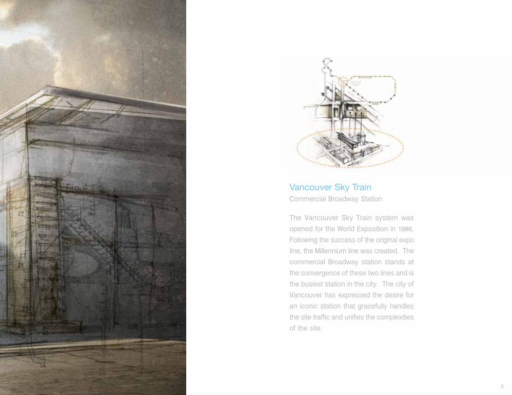
Vancouver Sky TrainCommercial Broadway Station
The Vancouver Sky Train system was
opened for the World Exposition in 1986.
Following the success of the original expo
line, the Millennium line was created. The
commercial Broadway station stands at
the convergence of these two lines and is
the busiest station in the city. The city of
Vancouver has expressed the desire for
an iconic station that gracefully handles
the site traffic and unifies the complexities
of the site.

6
Sketch models: searching for a dynamic form that would unify the complexities of the site.

7

8
TRUSS PARAMETERS CONSTANT DATUM LINE
MIDDLE TRUSS CONDITIONEND TRUSS CONDITION
END TRUSS CONDITION VARIABLE
SECTION B
am pm
25 kipsMAX MOMENT
MAX TENSION/COMPRESSION
MAX ALLOWABLE VARIABLEDISTANCE FOR 36” GLULAMTOP CORD IN LONGITUDINAL TRUSS ARRAY.
18 kips108 kips
23 kips C56 kips T16 kips T60 kips C
28’
70 kips T71 kips C

9
TRUSS PARAMETERS CONSTANT DATUM LINE
MIDDLE TRUSS CONDITIONEND TRUSS CONDITION
END TRUSS CONDITION VARIABLE
SECTION B
am pm
25 kipsMAX MOMENT
MAX TENSION/COMPRESSION
MAX ALLOWABLE VARIABLEDISTANCE FOR 36” GLULAMTOP CORD IN LONGITUDINAL TRUSS ARRAY.
18 kips108 kips
23 kips C56 kips T16 kips T60 kips C
28’
70 kips T71 kips C

10

11
Many levels of scale
were considered during
the design phase, from a
sketch for a new master
plan down to the station’s
joinery details.

12
13
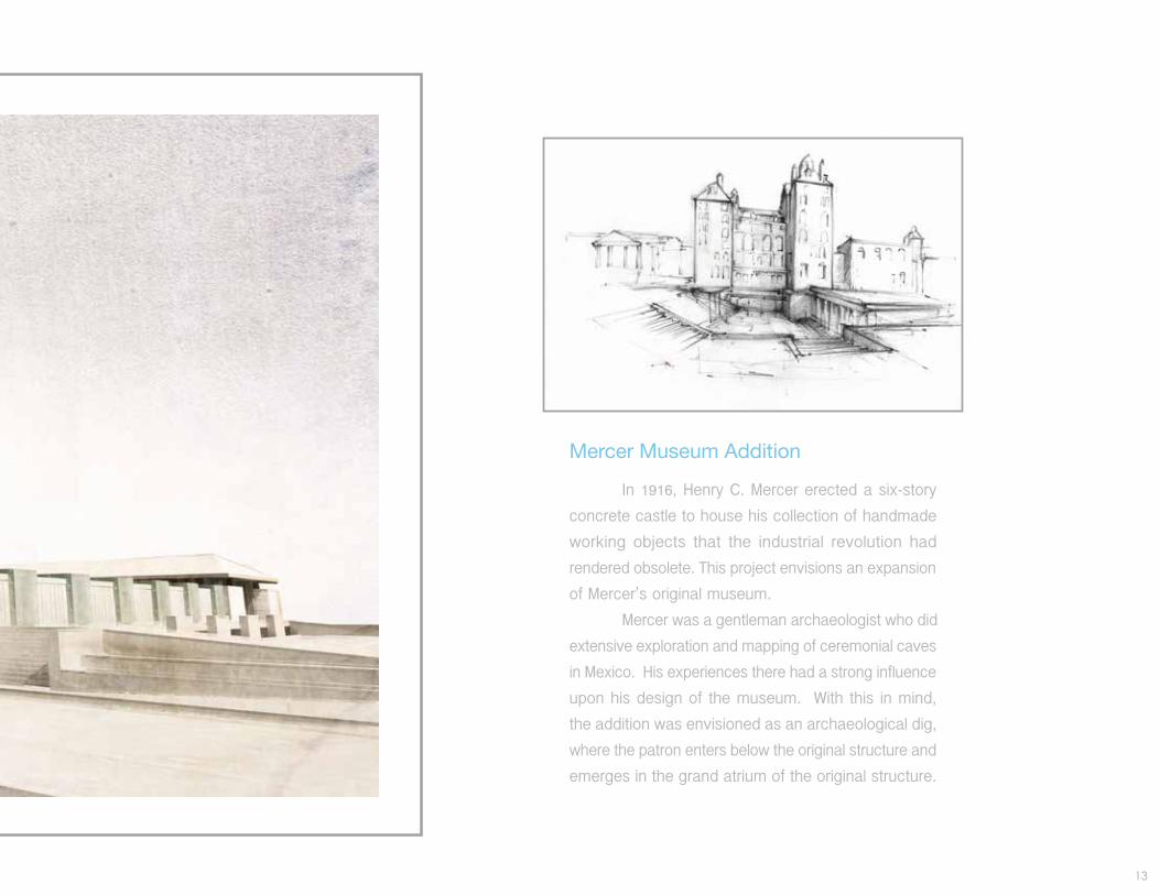
Mercer Museum Addition
In 1916, Henry C. Mercer erected a six-story
concrete castle to house his collection of handmade
working objects that the industrial revolution had
rendered obsolete. This project envisions an expansion
of Mercer’s original museum.
Mercer was a gentleman archaeologist who did
extensive exploration and mapping of ceremonial caves
in Mexico. His experiences there had a strong influence
upon his design of the museum. With this in mind,
the addition was envisioned as an archaeological dig,
where the patron enters below the original structure and
emerges in the grand atrium of the original structure.

14
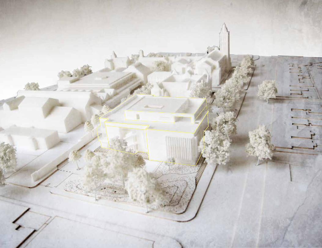
The site plan preserves the majority of
open space on the site that the museum
uses to house community camps and
festivals.

15
The new main entry is a quiet
feature that does not obstruct the
grandeur of the original museum.
Materials and building forms used
on the addition were chosen to
be complementary to the original
structure.

16
The museum addition combined with
the new public space was designed to
create a unifying landscape feature that
would provide a plinth for Henry Mercer’s
historic building.
Displaying History:New Public Space
Interacting with History:New Museum Space
Existing Museum Complex 1916 1930s

17

18
N
Site Forces:• Park Block Terminus
• Proximity to City Center
• Southern Access to Sunlight
An Urban Mausoleum for the City of Portland

19

20
The building massing was developed to capture light and
transform it, so that all who enter the space would be enveloped
by sacred light.
Preliminary massing investigations were made with many small
models and the use of a class site model.
FinalmassingPreliminarymassing

21

22
Preliminary visions of the grand space were
rendered in charcoal to communicate the
experiential qualities of the space. Later,
the daylighting was tested using physical
and computer models.
The building contains four memorial gardens.
The Mourning Garden, shown here, forms
an important processional space to a small
memorial chapel.

23

24
On the south side of the building is the Chapel of Light. This small memorial chapel lies on axis with a garden beyond. Water from a fountain in this garden flows through the chapel, and eventually flows down the front of the facade as a solemn reminder of the never-ending march of mortality and the ever-renewing cycle of life.

25

26

27
The Squirrel Cove Restaurant
This is a yet-to-be-built project designed by
Allen + Maurer Architects for the Klahoose
First Nation, a Coast Salish tribe.
For this interpretation of the scheme
provided by Allen + Maurer, the basic
footprint and profile of the building were
respected and served as inspiration for
site placement, orientation, facade and
interior design, as well as guidance for
an overall site plan.

28
Eugene
Portland
Seattle
Vancouver
Cortes Island
Longest view from site
Site
Sunrise/Sunset
1,000 ft
June
July
August
30º
13º
40º
29
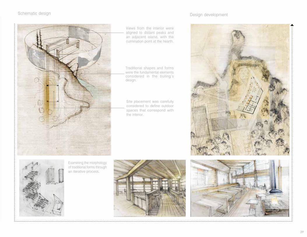
Schematic design Design development
Eugene
Portland
Seattle
Vancouver
Cortes Island
Longest view from site
Site
Sunrise/Sunset
1,000 ft
June
July
August
30º
13º
40º
Site placement was carefully considered to define outdoor spaces that correspond with the interior.
Views from the interior were aligned to distant peaks and an adjacent island, with the culmination point at the hearth.
Traditional shapes and forms were the fundamental elements considered in the builing’s design.
Examining the morphology of traditional forms through an iterative process.

30

31
The interior was designed to be holistically integrated with the site. The facade of the building was made of six accordian-style doors that fold up, allowing the heart of the structure to have a pavilion-like feeling.

32

33
Site Parameters:
The site parameters were very important
considerations in the design of the
interior of the building. The vastness
of the site is allowed to penetrate
through the structure guided by the
natural variation of the site which was
different on each side.
Western facade opens toward Squirrel
Cove.
The longest view is aligned through the
doorway to a peak on a distant island.
The eastern facade opens to the forest
which offers a screened view out into
the strait.
The back of the building was nestled
against the thick forest wall.
1
2
3
4
1
2
3
4
34

35
Project: East Ham Customer Service Center and Library
Responsibilities included building and assembling models, modeling facade details, and generating explanatory renderings for contractor and client review.
Summer Internship 2012
Rick Mather ArchitectsLondon, U.K.
36
11Rick Mather Architects © East Ham Civic Campus Technical College
North Entrance
Fire place
Columns 1 & 2
East Stair 01
West Stair 02
West Entrance
Plan of Other Major Elements Surveyed
Key
Green glazed tiles
Brown glazed tiles
Fireplace tiles
White glazed tiles and terracotta on West Stair 02. Tiles continue to level 1
5Rick Mather Architects © East Ham Civic Campus Technical College
A - Decorative Tile
24 damaged faces 1 x GR
1 x GR, 6 x BR
0
4 x GR, 4 x BR
D- 6”x3” Brick
17 x GR
3 x GR
10 x GR
36 x GR
F- Skirting Border30 x GR, 3 x BR
0
26 x GR (handrail)
3 x GR
E - 6”x4” Brick5 x GR
31 x GR
11 x GR
72 x GR,
G- 6”x6” Skirting Tile
0
0
0
4 x BR
R-Brown Field Tile
1 x BR
0
0
0
I.1- Decorative Tile
5 x GR
0
0
6 x GR
L- External Skirting Quadrant
0
6 x BR
7 x BR
30 x BR
P- Skirting Tile Pro�le 0
0
0
1 x BR
Q- Skirting Tile External Curved Pro�le
0
0
0
4 x GR
M- External Slip Tile
0
0
0
21 x FP
N- 3”x3” Mottles Fireplace TileTBC
TBC
TBC
TBC
O - Fireplace Hearth0
0
0
1 x FP
N.1 - 5x3/4 Yellow Fireplace Tile0
0
1
3 x FP
N.2 - Rounded External 3”x3”
2 x GR
1 x GR
1 x GR
0
S - Bullnose Tile
1 x GR
0
0
3 x GR
J- Rounded External 6”x3” Brick1 x GR
1 x GR
0
4 x GR
K- Symmetrical External Skirting Border
8 x GR, 1 x BR
0
2 x GR
0
H- Frame Pro�le
6 x GR
0
0
0
H.R- Frame Pro�le Right0
0
0
0
H.L- Frame Pro�le Left 0
0
0
0
I- Decorative Tile
2 x GR
0
12 x GR
7 x GR
B- Decorative Border3 x GR
2 x GR, 1 x BR
3 x GR, 6 x BR
9 x GR
C- Slip Tile
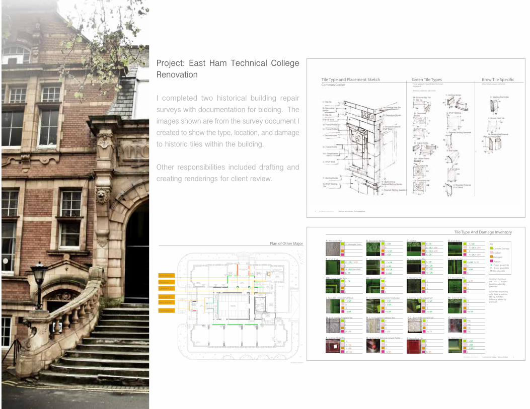
Tile Type And Damage Inventory
Inventory taken on site 13/8/12. Subject to con�rmation by specialist.
Quantities for pricing only. Final quantities TBC by Architect following advice by specialist.
Key
Cosmetic Damage
Cracked
Damaged
Replace
GR - Green glazed tileBR - Brown glazed tileFP- Fire place tile
4 Rick Mather Architects © East Ham Civic Campus Technical College
Tile Type and Placement Sketch Green Tile Types Brow Tile Speci�cThese types are replicated in the brown tiles as well
Dimensions shown are in mm
Dimensions shown are in mmCommon Corner
Project: East Ham Technical College Renovation
I completed two historical building repair
surveys with documentation for bidding. The
images shown are from the survey document I
created to show the type, location, and damage
to historic tiles within the building.
Other responsibilities included drafting and
creating renderings for client review.

37
16 Rick Mather Architects © East Ham Civic Campus Technical College
Wall 5.1
Wall 5.1
Wall 5.2
Wall 5.2
Wall 5.3
Wall 5.3
3 x J, 1 x G, 1 x F 0 1 x G, 1 x L
1 x F, 1 x B 1 x F 1 x B, 1 x S, 1 x F
0 3 x G 2 x G, 1 x C
7 x E, 1 x D, 1 x H.R 0 3 x E, 1 x H
Wall 5.1, 5.3, and 5.3
Wall 5.1
Wall 5.2
Wall 5.3
Remove Fixings
Remove Fixings
Timber panel and redundant services to be removed and tiles to be reinstated to match pattern.
Cosmetic
Cracked
Damaged
Replace
Cosmetic
Cracked
Damaged
Replace
Cosmetic
Cracked
Damaged
Replace
38
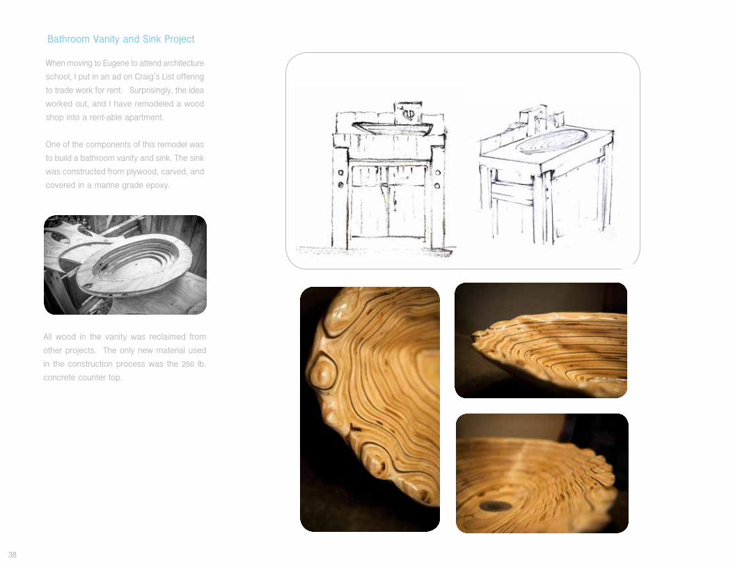
All wood in the vanity was reclaimed from
other projects. The only new material used
in the construction process was the 250 lb.
concrete counter top.
When moving to Eugene to attend architecture
school, I put in an ad on Craig’s List offering
to trade work for rent. Surprisingly, the idea
worked out, and I have remodeled a wood
shop into a rent-able apartment.
One of the components of this remodel was
to build a bathroom vanity and sink. The sink
was constructed from plywood, carved, and
covered in a marine grade epoxy.
Bathroom Vanity and Sink Project

39

40

41
This site model of the urban condition surrounding the
intersection of Burnside and 405 in Portland, was designed
and built as a collaborative effort between me and two
fellow students. It was important to us that the model
be informative and interactive for early building design;
however, it was also of great importance that the model
be a an inherently beautiful object. It was made from
hand cut wood blocks, CNC cut laminated plywood, and
sits on a laser cut steel base.
Class Site Model:

42
Profesional work

43
Rowell Brokaw ArchitectsEugene OR 2013
Northwest Community Credit Union Support Center
This class A office building with bank branch in the ground floor will serve as the new corporate headquarters for Northwest Community Credit Union. It is currently under construction in Eugene, OR.
I developed the presentation graphics as well as a series of 10 interior renderings along with the drawing on the right. Materials, and colors were carefully set up on layers in Photoshop to allow the interior design team to tweak and change them according to client wishes and design intent.
Beyond graphic representation, I helped with construction documents and branch furniture design.

44
Revit work- 49 east broad way

45
Rowell Brokaw ArchitectsEugene OR 2014
Concept renderings completed at the end of the planning and concept design phase of Eugene City Hall.

46
Rowell Brokaw ArchitectsEugene OR 2013-14
49 East Broadway will be a mixed-use in-fill building in downtown Eugene. I modeled the building in Revit up to this point of concept design in order to develop a code path and generate more accurate data for the building program Site response, building massing, and unit mix were also key components of the this concept design phase.
Building CommonResidentialCoreCommercial
A11
AREA SCHEDULE TOTAL
3BR507 3BR 818 SF507 3BR 842 SF
1660 SFBuilding CommonB300 Building Common 364 SFH100 Building Common 315 SFH400 Building Common 375 SFH500 Building Common 381 SF
1435 SFCommercial100 Commercial 1859 SF101 Commercial 1972 SF200 Commercial 5186 SF
9017 SFCoreC100 Core 298 SFC101 Core 212 SFC200 Core 311 SFC201 Core 210 SFC300 Core 303 SFC301 Core 207 SFC400 Core 300 SFC401 Core 175 SFC500 Core 296 SFC501 Core 195 SFC600 Core 90 SFC601 Core 219 SFCB100
Core 210 SF
3028 SFRentable
Rentable 112 SF112 SF
StorageB100 Storage 1920 SF
1920 SFGrand total 34333 SF
AREA SCHEDULE TOTAL
1 Loft504 1 Loft 495 SF504 1 Loft 353 SF505 1 Loft 496 SF505 1 Loft 351 SF
1695 SF1 Studio301 1 Studio 496 SF302 1 Studio 510 SF303 1 Studio 512 SF304 1 Studio 507 SF305 1 Studio 526 SF401 1 Studio 472 SF402 1 Studio 497 SF403 1 Studio 498 SF404 1 Studio 496 SF405 1 Studio 491 SF
5006 SF1BR306 1BR 688 SF307 1BR 802 SF406 1BR 708 SF407 1BR 833 SF
3030 SF2BR300 2BR 761 SF300 2BR 650 SF500 2BR 739 SF500 2BR 569 SF501 2BR 487 SF501 2BR 556 SF502 2BR 497 SF502 2BR 622 SF503 2BR 498 SF503 2BR 612 SF506 2BR 702 SF506 2BR 736 SF
7429 SF
1/64" = 1'-0"1 FL. 1
1/64" = 1'-0"2 FL. 2
1/64" = 1'-0"3 FL. 3
1/64" = 1'-0"4 FL. 4
1/64" = 1'-0"5 FL. 5
1/64" = 1'-0"6 FL. 6
1/64" = 1'-0"B FL. B

47
These conceptual renderings were designed to serve three important purposes. 1. To show the neighboring building owners that the new building would enhance the street face at ground level.2. To help envision and explore design ideas for the narrow courtyard between buildings.3. To show the city that the intention to cantilever into public right of way on three sides would enhance the public realm.
Building CommonResidentialCoreCommercial
A11
AREA SCHEDULE TOTAL
3BR507 3BR 818 SF507 3BR 842 SF
1660 SFBuilding CommonB300 Building Common 364 SFH100 Building Common 315 SFH400 Building Common 375 SFH500 Building Common 381 SF
1435 SFCommercial100 Commercial 1859 SF101 Commercial 1972 SF200 Commercial 5186 SF
9017 SFCoreC100 Core 298 SFC101 Core 212 SFC200 Core 311 SFC201 Core 210 SFC300 Core 303 SFC301 Core 207 SFC400 Core 300 SFC401 Core 175 SFC500 Core 296 SFC501 Core 195 SFC600 Core 90 SFC601 Core 219 SFCB100
Core 210 SF
3028 SFRentable
Rentable 112 SF112 SF
StorageB100 Storage 1920 SF
1920 SFGrand total 34333 SF
AREA SCHEDULE TOTAL
1 Loft504 1 Loft 495 SF504 1 Loft 353 SF505 1 Loft 496 SF505 1 Loft 351 SF
1695 SF1 Studio301 1 Studio 496 SF302 1 Studio 510 SF303 1 Studio 512 SF304 1 Studio 507 SF305 1 Studio 526 SF401 1 Studio 472 SF402 1 Studio 497 SF403 1 Studio 498 SF404 1 Studio 496 SF405 1 Studio 491 SF
5006 SF1BR306 1BR 688 SF307 1BR 802 SF406 1BR 708 SF407 1BR 833 SF
3030 SF2BR300 2BR 761 SF300 2BR 650 SF500 2BR 739 SF500 2BR 569 SF501 2BR 487 SF501 2BR 556 SF502 2BR 497 SF502 2BR 622 SF503 2BR 498 SF503 2BR 612 SF506 2BR 702 SF506 2BR 736 SF
7429 SF
1/64" = 1'-0"1 FL. 1
1/64" = 1'-0"2 FL. 2
1/64" = 1'-0"3 FL. 3
1/64" = 1'-0"4 FL. 4
1/64" = 1'-0"5 FL. 5
1/64" = 1'-0"6 FL. 6
1/64" = 1'-0"B FL. B

48
Since architecture school, drawing has become a very important part of my life. I spent hours as a student trying to understand how to bring life to a drawing. After graduating, I continue to enjoy spending much of my free time continuing in that pursuit whether on a lunch break or traveling abroad.
Drawing

During my capstone studio I became very interested in representing spatial perception, memory, and creative exploration through design drawings. Shown here are early studies representations of on the building feeling and spatial sequencing through the entry experience.

50
After work drawings.
One of my favorite activities to do after work is to come home and draw. These drawings allow me to design without limitations as well as enjoy the pure physical act of drawing, not worrying about an outcome. I enjoy watching ideas and media develop freely on the page without preconceived expectations or a clear picture where the work is going. The failure or success of a piece is of little consequence, joy is found in the act of making.

51
Shown here are two drawings out of a set of five that I entered in the Blank Space design competition. These drawings taken from my “after work drawing set” imagine a world where an entire societal history was formed around their ability to make architecture perform tasks and execute commands in much the same way that our society has become dependent on programs and computers to help us operate our contemporary civilization.

52
A gift, carved for my borther and his family.

53
I believe that beautiful objects come about through beautiful processes, and that the art of making a design is paramount to the success of the design itself. Therefore, working with my hands has always been an important part of my life. I love to create, to build, and to sculpt. When I am able to build my own designs, I find that work absolutely invigorating as well as deeply educational and fulfilling. My goal as a designer is to reveal beauty that unfolds through the process of creating, and I hope that the making of my designs will add to the beauty, life, and vitality of the world around them.