Jericho Agro-Industrial Park (JAIP) Mechanical Works ...
59
Jericho Agro-Industrial Park (JAIP) Mechanical Works Technical Specifications March, 2015
Transcript of Jericho Agro-Industrial Park (JAIP) Mechanical Works ...

Jericho Agro-Industrial Park (JAIP)
Mechanical Works
Technical Specifications
March, 2015

1
Mechanical works – List of manufacturers DRAINAGE AND RAIN WATER SYSTEM
No. Item (1) (2) (3)
1.
2.
3.
4.
Submersible pumps Manhole covers (cast iron) Stainless Steel pipes Steel pipes
Grundfos (Denmark)
Local
APEX (India)
Federal Steel Supply (USA)
ITT (Global)
FROCH (UK)
MRC Global
Flight (USA)
BRISMET (USA)
POTABLE WATER SYSTEM
No. Item (1) (2) (3)
1.
2.
3.
4.
5.
6.
Cold and hot water pipes valves Pressure Booster pump set included valves, headers, control system Overflow Flow meter Chlorination system Packaged Reverse Osmosis
Crane (UK)
Grundfos
(Denmark)
WATCO Manufacturing
Company
Badger Meter Europa GMBH
(Germany)
METITO (UAE)
BWT (UK)
Hattersley (UK)
ITT
FOSHAN DIBO
(China)
Honeywell (UK)
Grundfos (Germany)
IEM
(Germany)
Flight (USA)
B Meters (Italia)
Osmofilter (Spain)
2
No. Item (1) (2) (3)
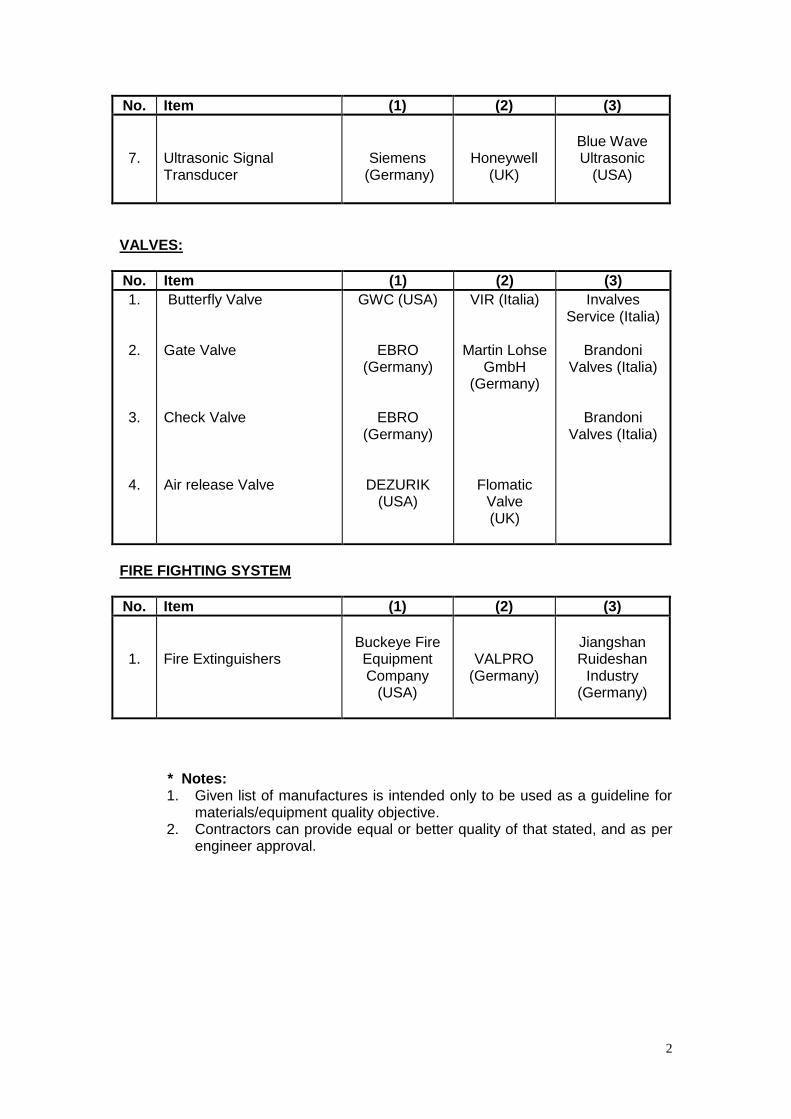
7.
Ultrasonic Signal Transducer
Siemens (Germany)
Honeywell (UK)
Blue Wave Ultrasonic
(USA)
VALVES:
No. Item (1) (2) (3)
1.
2.
3.
4.
Butterfly Valve Gate Valve Check Valve Air release Valve
GWC (USA)
EBRO (Germany)
EBRO (Germany)
DEZURIK (USA)
VIR (Italia)
Martin Lohse GmbH
(Germany)
Flomatic Valve (UK)
Invalves Service (Italia)
Brandoni
Valves (Italia)
Brandoni Valves (Italia)
FIRE FIGHTING SYSTEM
No. Item (1) (2) (3)
1.
Fire Extinguishers
Buckeye Fire Equipment Company
(USA)
VALPRO (Germany)
Jiangshan Ruideshan
Industry (Germany)
* Notes:
1. Given list of manufactures is intended only to be used as a guideline for materials/equipment quality objective.
2. Contractors can provide equal or better quality of that stated, and as per engineer approval.

3
PUMPS (PLUMBING)
.
PART 1 - GENERAL
1.1 DESCRIPTION
Hot water circulating pump, sump pump, sewage ejector pump, soft water
booster pump, waste water pump, and domestic water pressure booster
system.
1.2 QUALITY ASSURANCE
A. Domestic Water Pressure Booster System:
1. Components shall be furnished by a single manufacturer and the system
shall be the standard cataloged product of the manufacturer.
2. Shop Test: Water booster unit and its component parts shall undergo a
thorough electric and hydraulic operating test prior to shipment. Tests
shall include a system operating flow test from zero to 100 percent of
design flow rate under specified suction and system pressure conditions.
Certified performance curves shall be furnished.
B. Employee Instructions: Furnish the services of a competent, factory-trained
engineer or technician for eight hours to instruct operating and maintenance
personnel concerning the domestic water booster system.
1.3 SUBMITTALS
A. Submit in accordance with contract conditions, SAMPLES AND SHOP
DRAWINGS.
B. Manufacturer's Literature and Data:
1. Pump:
a. Manufacturer and model.
b. Operating speed.
c. Capacity.
d. Characteristic performance curves.
2. Motor:
a. Manufacturer.
b. Speed.
c. Current Characteristics and W (HP).
d. Efficiency.

4
C. Certificate of shop test for domestic water booster system. Provide certified
performance curves.
D. Certified copies of all the factory and construction site test data sheets and
reports.
E. Complete operating and maintenance manuals including wiring diagrams,
technical data sheets and information for ordering replaceable parts:
1. Include complete connection which indicates all components of the
system.
2. Include complete diagrams of the internal wiring for each item of
equipment.
3. Diagrams shall have their terminals identified to facilitate installation,
operation and maintenance.
1.4 APPLICABLE PUBLICATIONS
A. The publications listed below form a part of this specification to the extent
referenced. The publications are referenced in the text by the basic
designation only.
B. National Electrical Manufacturers Association (NEMA):
ICS6-93 (R2001)................... Industrial Control and Systems Enclosures
250-03 .................................. Enclosures for Electrical Equipment (1000 Volts
Maximum)
C. American Society of Mechanical Engineers (ASME):
Boiler and Pressure Vessel Code: 2002
Section VIII ........................... Pressure Vessels, Division I and II.
D. Underwriters' Laboratories, Inc. (UL):
508-99 (R2002) .................... Safety Industrial Control Equipment
PART 2 - PRODUCTS
2.1 SUMP PUMP
A. Centrifugal, submersible, designed for 37 degrees C maximum. Driver shall
be electric motor. Support shall be substantial rigid type. Provide perforated,
nonferrous suction trainer. Systems may include one, two, or more pumps
with alternator as required by conditions:

5
1. Pump housings may be cast iron, bronze, or stainless steel. Cast iron
housings for submersible pumps shall be epoxy coated.
B. Impeller: Brass or bronze.
C. Shaft: Bronze, stainless steel or other approved corrosion-resisting metal.
D. Bearings: As required to hold shaft alignment, anti-friction type for thrust. For
vertical sump pumps, if bearings for shaft in sump require lubrication, provide
a method to lubricate bearings without opening the sump or removing the
pump.
E. Characteristics: Head capacity characteristics shall not permit overloading at
any point of the curve.
F. Motor: Maximum 40 degrees C ambient temperature rise, completely
enclosed, voltage and phase as shown in schedule on Electrical drawings
conforming to NEMA 250 -Type 6P. Motor capacity to operate pump without
overloading the motor. Refer to Section 16150, MOTORS.
G. Starting Switch: Manually-operated, tumbler type, as specified
H. Automatic Control and Level Alarm: Furnish a control panel in a Nema 1
enclosure for indoors or in a Nema 4X enclosure for outdoors. The controls
shall be suitable for operation with the electrical characteristics listed on the
Electrical drawings. The control panel shall have a level control system with
switches to start and stop pumps automatically, and to activate a high water
alarm. The level control system will include sensors in the sump that detect
the level of the liquid. The sensors may be float type switches, ultrasonic level
sensors, transducers, or other appropriate equipment. The high water alarm
shall have a red beacon light at the control panel and a buzzer, horn, or bell.
The alarm shall have a silencing switch. Provide auxiliary contacts for remote
alarming to the Energy Control Center (ECC). The circuitry of the control
panel shall include:
-power switch to turn on/off the automatic control mechanism
-HOA switches to manually override automatic control mechanism
-run lights to indicate when pumps are powered up
-level status lights to indicate when water in sump has reached the
predetermined on/off and alarm levels
-magnetic motor contactors
-disconnect/breaker for each pump
-automatic motor overload protection

6
1. For a duplex system, provide an alternating relay to automatically
alternate leadoff and standby duties of each pump of a duplex unit at the
end of each pumping cycle. Standby pump shall start when water level in
sump rises to a predetermined level that indicates excessive inflow or
failure of the lead pump.
2. Sensors that detect the level of water in the sump shall be so arranged as
to allow the accumulation of enough volume of liquid below the normal on
level that the pump will run for a minimum cycle of one minute. Sensors
shall be located to activate the alarm adequately before the water level
rises to the inlet pipe.
3. Provide two separate power supplies to the control panel, one for the
control/alarm circuitry and one for power to the pump motors. Each power
supply is to be fed from its own breaker so that if a pump overload trips a
breaker, the alarm system will still function. Each power supply is to be
wired in its own conduit.
4. Wiring from the sump to the control panel shall have separate conduits for
the pump power and for the sensor switches. All conduits are to be sealed
at the basin and at the control panel to prevent the intrusion of moisture
and of flammable and/or corrosive gases.
I. Sump: Furnish cast iron or fiberglass basin with gas tight covers. Cover shall
have 280 mm by 380 mm (11-inch by 15-inch) manhole with bolted cover,
vent connection, openings for pumps and controls. Sump shall be sized to
allow an adequate volume of water to accumulate for a minimum one minute
cycle of pump operation.
J. Provide a check valve and gate valve in the discharge of each pump. Where
a submersible pump is installed, drill a 3/16” diameter vent hole in the piping
below the check valve beneath the cover of the sump, to expel any air
entrapped beneath the check valve.
K. Removal/Disconnect System: In a system utilizing a submersible pump,
where sump depth, pump size, or other conditions make removal of the pump
unusually difficult or unsafe, a removal/disconnect system shall be provided.
The system will consist of a discharge fitting mounted on vertical guide rails
attached to the sump. The pump shall be fitted with an adapter fitting that
easily connects to/disconnects from the discharge fitting as the pump is
raised from or lowered into the sump. The discharge piping will connect to
the discharge fitting so that it is not necessary to disconnect any piping in
order to remove the pump. Where the sump depth is greater than five feet or

7
other conditions exist to make the removal of the pump difficult or hazardous,
the system shall include a rail guided quick disconnect apparatus to allow the
pump to be pulled up out of the sump without workers entering the sump and
without disconnecting the piping.
2.3 SEWAGE EJECTOR PUMP
A. Centrifugal, submersible, designed for 40 degrees C maximum water service.
Driver shall be electric motor. Support shall be substantial rigid type. Systems
may include one, two, or more pumps as required by conditions. Where
needed grinder pumps may be installed. Where hazardous environment
condition exists, explosion proof pumps shall be installed.
1. Pump housings may be cast iron, bronze, or stainless steel. Cast iron
housings for submersible pumps shall be epoxy coated.
B. Impeller: Brass or bronze, non-clog, to accommodate 65 mm (2-1/2 inch)
solids except for ginder pumps.
C. Shaft: Bronze, stainless steel or other approved corrosion-resisting metal.
D. Bearings: As required to hold shaft alignment, anti-friction type for thrust. For
vertical sump pumps, if bearings for shaft in sump require lubrication, provide
a method to lubricate bearings without opening the sump or removing the
pump.
E. Characteristics: Head capacity characteristics shall not permit overloading at
any point of the curve.
F. Motor: Maximum 40 degrees C ambient temperature rise, completely
enclosed, voltage and phase as shown in schedule on Electrical drawings
conforming to NEMA 250 -Type 6P. Motor capacity to operate pump without
overloading the motor.
G. Starting Switch: Manually-operated, tumbler type, as specified.
H. Automatic Control and Level Alarm: Furnish a control panel in a Nema 1
enclosure for indoors or in a Nema 4X enclosure for outdoors. The controls
shall be suitable for operation with the electrical characteristics listed on the
Electrical drawings. The control panel shall have a level control system with
switches to start and stop pumps automatically, and to activate a high water
alarm. The level control system will include sensors in the sump that detect
the level of the liquid. The sensors may be float type switches, ultrasonic level
sensors, transducers, or other appropriate equipment. The high water alarm
shall have a red beacon light at the control panel and a buzzer, horn, or bell.

8
The alarm shall have a silencing switch. Provide auxiliary contacts for remote
alarming to the Energy Control Center (ECC). The circuitry of the control
panel shall include:
- Power switch to turn on/off the automatic control mechanism
- HOA switches to manually override automatic control mechanism
- Run lights to indicate when pumps are powered up
- Level status lights to indicate when water in sump has reached the
predetermined on/off and alarm levels
- Magnetic motor contactors
- Disconnect/breaker for each pump
- Automatic motor overload protection
1. For a duplex system, provide an alternating relay to automatically
alternate leadoff and standby duties of each pump of a duplex unit at the
end of each pumping cycle. Standby pump shall start when water level in
sump rises to a predetermined level that indicates excessive inflow or
failure of the lead pump.
2. Sensors that detect the level of water in the sump shall be so arranged as
to allow the accumulation of enough volume of liquid below the normal on
level that the pump will run for a minimum cycle of one minute. Sensors
shall be located to activate the alarm adequately before the water level
rises to the inlet pipe.
3. Provide two separate power supplies to the control panel, one for the
control/alarm circuitry and one for power to the pump motors. Each power
supply is to be fed from its own breaker so that if a pump overload trips a
breaker, the alarm system will still function. Each power supply is to be
wired in its own conduit. Wiring from the sump to the control panel shall
have separate conduits for the pump power and for the sensor switches.
All conduits are to be sealed at the basin and at the control panel to
prevent the intrusion of moisture and of flammable and/or corrosive
gases.
I. Sump: Furnish cast iron or fiberglass basin with gas tight covers. Covers shall
have 280 mm by 380 mm (11-inch by 15-inch) manhole with bolted cover,
vent connection, and openings for pumps and controls.
J. Provide a check valve and gate valve in the discharge from each pump where
a submersible pump is installed, drill a 3/16” diameter vent hole in the piping
below the check valve beneath the cover of the sump, to expel any air
entrapped beneath the check valve.

9
K. Removal/Disconnect System: In a system utilizing a submersible pump,
where sump depth, pump size, or other conditions make removal of the pump
unusually difficult or unsafe, a removal/disconnect system shall be provided.
The system will consist of a discharge fitting mounted on vertical guide rails
attached to the sump. The pump shall be fitted with an adapter fitting that
easily connects to/disconnects from the discharge fitting as the pump is
raised from or lowered into the sump. The discharge piping will connect to the
discharge fitting so that it is not necessary to disconnect any piping in order to
remove the pump.
Where the sump depth is greater than five feet or other conditions exist to
make the removal of the pump difficult or hazardous, the system shall include
a rail guided quick disconnect apparatus to allow the pump to be pulled up out
of the sump without workers entering the sump and without disconnecting the
piping.
PART 3 - EXECUTION
3.1 TEST
A. Make tests as recommended by product manufacturer and listed standards
and under actual or simulated operating conditions and prove full compliance
with design and specified requirements. Tests of the various items of
equipment shall be performed simultaneously with the system of which each
item is an integral part.
B. When any defects are detected, correct defects and repeat test.
- - - E N D - - -

10
SPECIFICATIONS - DETAILED PROVISIONS Section 02734 - Water Well Drilling, Casing & Testing
TABLE OF CONTENTS
1.0 GENERAL......................................................................................................................... 2 1.01 DESCRIPTION....................................................................................................... 2 1.02 WELL CONSTRUCTION STANDARDS ............................................................... 2 1.03 WELL CONSTRUCTION SUMMARY ................................................................... 2 1.04 CONTRACTOR EQUIPMENT................................................................................ 3 1.05 CONTRACTOR RESPONSIBILITIES ................................................................... 4 1.06 QUALIFICATIONS AND QUALITY ASSURANCE................................................. 5 1.07 RECORDS ............................................................................................................. 5 1.08 SUBMITTALS......................................................................................................... 7 1.09 GUARANTEE......................................................................................................... 7 1.10 SUPERVISION AND COOPERATION.................................................................. 8
2.0 CONSTRUCTION (Technical Provisions) ...................................................................... 8 2.01 MOBILIZATION....................................................................................................... 8 2.02 NOISE CONTROL .................................................................................................. 10 2.03 CONDUCTOR BOREHOLE CASING AND SANITARY SEAL ............................. 11 2.04 PILOT BOREHOLE.................................................................................................. 14 2.05 DRILLING FLUID..................................................................................................... 15 2.06 DOWNHOLE GEOPHYSICAL SURVEYS .............................................................. 17 2.07 ISOLATED AQUIFER ZONE TESTING................................................................... 19 2.08 BOREHOLE SEAL................................................................................................... 22 2.09 FINAL REAMED BOREHOLE ................................................................................. 23 2.10 CALIPER SURVEY.................................................................................................. 24 2.11 WELL CASING AND ACCESSORY TUBING......................................................... 26 2.12 GRAVEL PACK........................................................................................................ 32 2.13 ANNULAR SEALS .................................................................................................. 33 2.14 UPPER ANNULAR GROUT SEAL.......................................................................... 34 2.15 MECHANICAL WELL DEVELOPMENT.................................................................. 36 2.16 CHEMICAL DEVELOPMENT.................................................................................. 38 2.17 MOBILIZATION AND DEMOBILIZATION OF TEST PUMP AND APPURTENANCES .......................................................................... 40 2.18 PUMPING DEVELOPMENT................................................................................... 42 2.19 RESET INTAKE DEPTH OF TEST PUMP............................................................. 44 2.20 STEP-DRAWDOWN AND AQUIFER TESTS........................................................ 45 2.21 FLOW METER SURVEY........................................................................................ 49

11
2.22 COLOR VIDEO CAMERA SURVEY...................................................................... 50 2.23 ALIGNMENT/DEVIATION TESTING OF WELL ................................................... 52 2.24 WELL DISINFECTION AND CAPPING ................................................................ 52 2.25 STANDBY TIME..................................................................................................... 54 2.26 DESTRUCTION OF NEW WELL .......................................................................... 54
SECTION 02734 WATER WELL DRILLING, CASING & TESTING
1.0 GENERAL
1.01 DESCRIPTION
Provide all labor, equipment, materials, and forces necessary to provide the Engineer with a new, complete and fully developed municipal-supply water well. The new well will be drilled and completed in such a manner as to produce from all water bearing zones of acceptable properties and water quality identified by the Engineer. The final well design will be determined after examination of the formation samples, sieve analyses of drill cuttings, down hole geophysical logs and results of isolated aquifer zone sampling. If water-bearing zones drilled are considered adequate to produce the desired quantity and quality of water, the well will be completed, otherwise the pilot borehole will be destroyed and work under the contract terminated. Project-specific well requirements are presented in the provision supplement(s) found at the end of this detailed provision.
1.02 WELL CONSTRUCTION STANDARDS The new well shall be constructed in compliance with; (1) Palestine Water Authority
(PWA) common requirements (4) American Water Works Association (AWWA) Standard for Water Wells (AWWA A100-97 or later).
1.03 WELL CONSTRUCTION SUMMARY Except as noted in the provision supplement(s), the general work required for well
construction, development and testing shall include, but may not be limited to the following:
A. Move on and off the well site. B. Install temporary security fencing around all construction, material storage and temporary water disposal areas. C. Setup and maintain a temporary field office, electrical and telephone service and
sanitary facilities. D. Install temporary noise control barrier walls and equipment as necessary to meet specified noise level limits. E. Provide at least three temporary tanks for settlement of solids from development
water prior to discharge to the point of discharge. F. Provide temporary pipeline and appurtenances required to convey well development
and testing water to the point of discharge. G. Install permanent conductor casing and sanitary seal. H. Drill and sample pilot borehole. I. Conduct down hole geophysical surveys in the pilot borehole. J. Conduct isolated aquifer zone testing in the pilot borehole as specified by the
Engineer. Retain an analytical testing laboratory to complete water sample analyses specified. K. Ream the pilot borehole to the specified final diameters and depths. L. Complete a caliper survey of the final reamed borehole.

12
M. Install blank and screened well casing, tubing, gravel pack, annular seals, and annular grout seal in accordance with the Plans and Specifications, and final well design specified by the Engineer.
N. Complete initial well development by air-lift swabbing (mechanical development). O. Install a test pump at a capacity and intake depth specified by the Engineer. P. Complete well development by pumping and surging. Q. Conduct well production tests (step-drawdown and constant rate discharge tests). R. Complete a flow meter survey during well testing as specified by the Engineer. S. Conduct a color video survey of the completed well. T. Conduct a well alignment test by gyroscopic methods. U. Disinfect the completed well. V. Construct a well pump foundation (Engineer option). W. Complete final site cleanup and restoration to the satisfaction of the Engineer. X. Provide all records required by the specifications and requested by the Engineer.
1.04 CONTRACTOR EQUIPMENT A. General
The Contractor shall provide all equipment, tools, supplies, materials, power and
personnel required to complete the work. The Contractor shall provide fencing as needed to secure the well site and entire work area used for material storage and drilling operations including areas occupied by the field office, construction equipment, engines, motors and other equipment. The Contractor shall provide a temporary field office, and sanitary facilities as described in the Special Conditions.
B. Drilling Equipment The new well shall be drilled using a reverse circulation rotary drilling method in hick the uncased wall of the drill borehole is held in place at all times with a circulating fluid. The Contractor will provide a complete drilling unit, all tools, accessories, power, lighting, water, other equipment and experienced personnel necessary to conduct efficient drilling operations at the site. The drilling equipment shall be in good condition and of sufficient mast capacity to drill the borehole required by these specifications to a depth specified in the Drawings (Section P, Standard and Construction Drawings). All drilling equipment including mast and draw-works, air compressors, drilling fluid pumps, drill pipe, etc., must be of requisite size, sufficient capacity, and in suitable condition to drill and set casing to the anticipated depths in the well (see the provision supplement(s), for depth requirements). The mast and all running gear (hoists, cables, etc.) shall have sufficient and demonstrated capacity to lift two (2) times the buoyant weight of either the drill string or the blank and screened well casing assembly (whichever is greater). The drill rig utilized must have the ability to fully lift and land the anticipated casing loads without the use of cranes, float plugs, or other similar methods. The Contractor shall submit, upon request, detailed information documenting the capacity of the various components of the rig used including, but not limited to, derrick/ mast capacity, drill pipe type and rating, all line and hook load capacities, air compressor rating, mud pump capacity, etc. All drill pipes must utilize threaded flush or upset tool joints, or equal, as approved by the Engineer.
Drilling equipment shall be disinfected on site prior to use. The methods, chemicals and dosages employed shall be approved by the Engineer
C. Mud Tanks
Excavated mud pits will not be allowed. Portable tanks are required which allow the drill cuttings to settle. The tanks will have a minimum of three chambers and have sufficient capacity to allow for proper settling of drill cuttings as approved by the Engineer. The tanks will be cleaned periodically to ensure that the drilling fluid remains clean prior to its re-entry into the borehole. At no time shall the height of the material settled in the tanks exceed two feet. Drilling fluid re-circulated to the borehole shall not contain in excess of 5 percent sand. Materials cleaned from the tanks shall be hauled off-site for proper disposal at the Contractor’s expense.
13
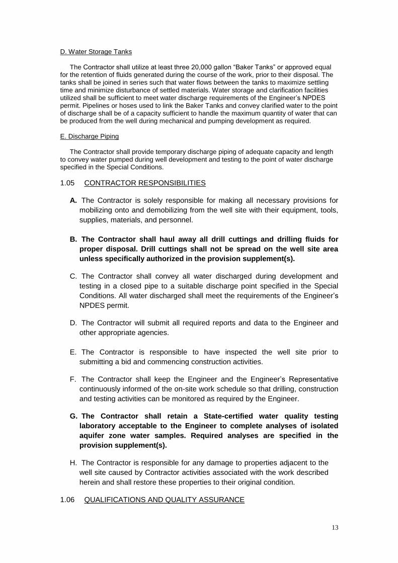
D. Water Storage Tanks
The Contractor shall utilize at least three 20,000 gallon “Baker Tanks” or approved equal for the retention of fluids generated during the course of the work, prior to their disposal. The tanks shall be joined in series such that water flows between the tanks to maximize settling time and minimize disturbance of settled materials. Water storage and clarification facilities utilized shall be sufficient to meet water discharge requirements of the Engineer’s NPDES permit. Pipelines or hoses used to link the Baker Tanks and convey clarified water to the point of discharge shall be of a capacity sufficient to handle the maximum quantity of water that can be produced from the well during mechanical and pumping development as required.
E. Discharge Piping
The Contractor shall provide temporary discharge piping of adequate capacity and length to convey water pumped during well development and testing to the point of water discharge specified in the Special Conditions.
1.05 CONTRACTOR RESPONSIBILITIES
A. The Contractor is solely responsible for making all necessary provisions for
mobilizing onto and demobilizing from the well site with their equipment, tools,
supplies, materials, and personnel.
B. The Contractor shall haul away all drill cuttings and drilling fluids for
proper disposal. Drill cuttings shall not be spread on the well site area
unless specifically authorized in the provision supplement(s).
C. The Contractor shall convey all water discharged during development and
testing in a closed pipe to a suitable discharge point specified in the Special
Conditions. All water discharged shall meet the requirements of the Engineer’s
NPDES permit.
D. The Contractor will submit all required reports and data to the Engineer and
other appropriate agencies.
E. The Contractor is responsible to have inspected the well site prior to
submitting a bid and commencing construction activities.
F. The Contractor shall keep the Engineer and the Engineer’s Representative
continuously informed of the on-site work schedule so that drilling, construction
and testing activities can be monitored as required by the Engineer.
G. The Contractor shall retain a State-certified water quality testing
laboratory acceptable to the Engineer to complete analyses of isolated
aquifer zone water samples. Required analyses are specified in the
provision supplement(s).
H. The Contractor is responsible for any damage to properties adjacent to the
well site caused by Contractor activities associated with the work described
herein and shall restore these properties to their original condition.
1.06 QUALIFICATIONS AND QUALITY ASSURANCE

14
The Contractor shall have been engaged in the business of well construction using the reverse circulation drilling method and test pumping of wells with a depth, diameter and capacity equivalent to those anticipated for the new well for a period of at least fifteen (15) years. The Contractor shall submit a list of the last three (3) municipal well owners for whom the Contractor has drilled equivalent municipal-supply water wells. The lists of references shall include (as applicable) the owner’s name and address, casing diameter, type, depth, production capacity, specific capacity, sand production and well destruction procedures and methods.
1.07 RECORDS
The Contractor shall keep a daily log and progress record at the site readily available for inspection during drilling of the pilot borehole, construction and testing of the new well. Specific records associated with each on-site activity are listed in Section 2.0 Construction (Technical Provisions) of this detailed provision. In general, the Contractor shall keep records providing the following information:
A. Driller’s description of formation materials penetrated at 10-foot intervals and at each
major change of formation (from both the conductor casing borehole and pilot borehole).
B. Log of drill bit types, diameters and changes. C. Drilling fluid properties at 4-hour intervals including mud weight, Marsh funnel viscosity,
sand content, solids content, water additions and mud additives used.
D. Collection of one (1) set of representative formation samples from the conductor casing borehole and pilot borehole. Samples shall be collected over a 10-foot interval and at each major change in formation from the ground surface to the full depth of the borehole. The method of sample collection shall be approved by the Engineer. Samples collected off a shaker screen are not acceptable unless specifically approved by the Engineer. Samples shall be preserved in one-gallon size, heavy (freezer) weight, zip-lock type, plastic bags labeled with the well name, date, time and depth interval.
E. Results of sieve analyses of formation samples requested by the Engineer and
completed by the Contractor. See the provision supplement(s) for number of analyses required.
F. Results of down hole geophysical surveys completed in the pilot borehole. G. Setup and results of each isolated aquifer zone test conducted in the pilot borehole
including dates, times, intervals sampled, schedule of annular fill materials, development times and results, water sampled, depth to water and discharge measurements.
H. Borehole reaming activities.
I. Results of caliper survey of the final reamed borehole.
J. Results of sieve analyses completed by the Contractor of representative samples of gravel pack materials delivered on-site prior to casing installation. See the provision supplement(s) for number of samples.
K. Well construction activities including final schedule and diagram of installed blank and
screened well casing, gravel feed tube, air vent tube, sounding tube(s) and annular fill materials.
L. Cross-sectional diagram illustrating the design and structure of the splice section in the
well casing for entry of the sounding tube.

15
M. Installation of test pump and appurtenances including summary descriptions of pump
type, diameter, intake depth, make, model, horse power, rated capacity, flow control valves, flow meter and discharge piping.
N. Records of well development by mechanical methods (swabbing and air-lift pumping)
and pumping methods using a test pump. Records of pumping test results using a test pump. Records shall be maintained at the time intervals requested showing static water level, production rate, pumping water level, drawdown, gravel pack settlement and additions, water clarity, depth interval developed and other information requested by the Engineer.
O. Sand production test results. P. Setup and results of flow meter survey. Q. Setup and results of well alignment and deviation surveys. R. Records on chlorine concentrations used for well development and disinfection. S. Results of the down hole color video survey of the completed well. T. Schedule of well destruction, if applicable.
1.08 SUBMITTALS
All records shall be available to the Engineer at all times at the job site. Section 2.0 -Construction (Technical Provisions) of this detailed provision lists submittals required for specific well construction and destruction activities. All records shall be legible, typed as appropriate, and submitted to the Engineer on 8 1/2” x 11” paper. Required submittals and submittal schedules are summarized in Table 02734-1. Submittals shall be delivered to the Construction Administrative Representative identified by the Engineer at the Preconstruction Conference.
1.09 GUARANTEE
A. General
For a period of three (3) years after acceptance of the well by the Engineer, the Contractor shall make the following guarantees and accept the following responsibilities concerning their work:
1. Sand production shall be less than five (5) parts per million (ppm) within fifteen (15)
minutes after start of pumping at the agreed production rate of the well. 2. Sand production shall be less than one (1) ppm within two (2) hours after start of
pumping at the agreed production rate of the well. 3. The well casing and screen shall remain intact throughout its entire length. 4. Plumpness and alignment of the well shall remain within the tolerances set forth in
these specifications. B. Demonstration of Compliance
1. To demonstrate compliance with the above, the Contractor shall perform at monthly periods for the first three (3) months of operation, and at periods of every six (6) months, thereafter, a test of the well. Representatives of the Engineer shall witness these tests and certified copies of the test results shall be furnished. The tests shall consist of a Rossum sand test of the well for a minimum period of two hours after

16
cycling, and all other information required, to check compliance with the above guarantees.
2. To insure compliance with the terms of this section, the Contractor shall furnish a
three (3) year maintenance bond.
1.10 SUPERVISION AND COOPERATION
The Contractor shall provide a qualified and experienced foreman and drilling superintendent, one of who shall be constantly in attendance throughout drilling and construction of the new well. In addition to directing all well construction and testing, the foreman shall be capable of coordinating the work with all personnel, subcontractors, and the Engineer so that the overall project is successfully executed and completed without undue conflicts or delays. 2.0 CONSTRUCTION (Technical Provisions)
General requirements, materials and execution for construction wells are presented in the following sections. Contract-specific requirements are presented in the provision supplement(s). Well locations, standard and construction drawings, figures and tables are shown in Section P,Standard and Construction Drawings.
2.01 MOBILIZATION PART 1 – GENERAL
A. Description
Mobilization shall include: (1) transportation of personnel, equipment, and operating supplies to and from the well site, (2) establishment of temporary fencing, field office, power and telephone service, and portable sanitary facilities, (3) obtaining an adequate source of fresh water, (4) setup of temporary water tanks, discharge line and appurtenances, (5) excavation of temporary water storage ponds as required, and (6) other preparatory work required to complete construction of a new well including equipment and related facilities.
B. Related Work Specified Elsewhere
1. General Conditions, Section F-42, Measurement and Payment. 2. Pre-bid Walk Through - Special Conditions. 3. Pre-construction Conference - Special Conditions.
C. Submittals
Well Driller’s Permit from Riverside County Department of Environmental Health Services.
D. Measurement and Payment Payment for mobilization shall be at the lump sum price bid.
PART 2 – MATERIALS Requirements for Contractor equipment are specified in Section 1.04.
PART 3 - EXECUTION A. The Contractor shall install appropriate fencing around the entire construction area
including the well, material storage and temporary water disposal areas. Fencing shall be adequate to ensure the safety and security of equipment, materials, on-site personnel and local residents.
B. Temporary water service for construction purposes will be supplied by the contractor
in accordance with the procedures described in the Special Conditions and established at the Pre-bid Walk Through.
17
C. The Contractor shall provide 220-volt power and telephone service to the Field Office and shall provide portable sanitary facilities for use by all personnel connected with this well project. These facilities shall remain in place during all phases of the work.
D. The Contractor shall keep the well site free from accumulations of waste materials,
rubbish, and other debris resulting from the work. At completion of the work, the Contractor shall remove all waste materials, rubbish, and debris from and about the well site as well as all tools, construction equipment, fuel tanks, machinery, temporary structures, and surplus materials. The Contractor shall leave the site clean and ready for use by the client. The Contractor shall restore all temporary work areas at the site to their original condition.
E. The Contractor shall prevent damage to the well site and adjacent properties
associated with pumping water during drilling, development, or testing or due to interruption or diversion of storm or wastewater during execution of the work.
F. Dirt and sediment shall be kept out of water disposal/drain lines at all times. The
Contractor shall properly dispose of all drilling, waste, and nuisance water. G. Well development and testing water shall be conveyed to the discharge location
specified in the Special Conditions. Water discharges shall be conducted under the Engineer's permit.
H. Drill cuttings and drilling fluids shall be removed from the well site and properly disposed by the Contractor.
2.02 NOISE CONTROL
PART 1 – GENERAL
A. Description
This section covers the installation of noise control barrier walls and other measures required to meet specified noise limits. Project-specific requirements are summarized in the provision supplement(s) and will be discussed at the Pre-bid Walk Through.
B. Measurement and Payment
Payment for installation and removal of noise control barrier walls shall be included in price.
PART 2 - MATERIALS AND EQUIPMENT
A. Equipment and materials employed for noise suppression shall include, but
are not limited to, equipping all internal combustion engines with critical
residential silencers (mufflers), installing sound blankets over equipment,
shielding noise-producing equipment and installing noise control barrier
walls.
B. If required, barrier walls installed shall consist of fiberglass-filled curtains and shall have adequate transmission loss and a minimum wall height of 20 feet. Noise control barrier walls shall be designed by a registered civil engineer. The design shall preclude structural failure due to such factors as winds, shear, shallow soil failure, earthquakes, and erosion. The length, height, and location of noise control barrier walls shall be adequate to assure proper acoustical performance.
PART 2 – EXECUTION
A. Noise suppression shall be practiced at all times to minimize disturbance to persons living or working nearby, and to the general public. Noise control measures shall be installed to direct the greatest noise emissions away from these receptors.

18
Operations shall be conducted in a manner to minimize noise generation consistent with the execution of the contract in a timely and economic manner.
B. Noise control barrier walls and equipment shall be installed as needed to
achieve a noise level of 65 db or less at the property lines. Noise levels in
excess of 65 db shall be allowed only during critical operations for brief
periods of time. Contractor shall make every reasonable effort to minimize
noise levels during nighttime operations.
2.03 CONDUCTOR BOREHOLE, CASING AND SANITARY SEAL
PART 1 – GENERAL
A. Description
This item includes drilling a conductor borehole, installation of conductor casing and installation of a cement grout sanitary seal in the annulus between the borehole and conductor casing to the minimum depth specified in the provision supplement(s). The sanitary seal installed shall meet the requirements of PWA requirements.
B. Submittals and Notifications
1. Certified test reports to show compliance with both the physical and
chemical properties of the steel.
2. Cement weigh or batch tickets.
3. The Contractor shall notify the Engineer at least 24 hours in advance of commencing drilling. The Contractor shall notify the Engineer and Riverside JAIP at least 48 hours in advance of setting the conductor casing and cement grout sanitary seal around the conductor casing. Unless pre-approved, installation shall not proceed without Engineer site inspection.
C. Measurement and Payment
1. Payment for this work item will be based on the unit price bid for the vertical meter of continuous grout seal placed adjacent to the conductor casing measured from the ground surface, excluding any lower portions of the annulus backfilled with non-grout materials. Payment shall include all materials, labor, tools, and equipment required to drill the conductor borehole, collect formation samples, protect the borehole from collapse, supply and install conductor casing, and supply and install the cement grout sanitary seal.
2. A conductor casing and sanitary seal installed to a depth less than the minimum
specified in the bid schedule will not be accepted for payment and shall be replaced by the Contractor at the Contractor’s expense.
PART 2 – MATERIALS
A. Conductor Casing
1. The conductor casing diameter, wall thickness and material shall be as specified in the provision supplement(s).
2. The conductor casing shall not be fabricated in less than 20-feet lengths. It shall be spiral welded or contain one longitudinal seam parallel to the casing axis and not more than one circumferential seam in 3 meters, or as otherwise approved by the Engineer. All spiral or longitudinal and circumferential seams shall be butt-welded with shielded arc electrodes to assure full fusion with the parent metal and complete penetration.
3. The ends of each joint shall be machine-beveled.

19
4. All joints in the conductor casing shall be securely welded in continuous passes and shall be watertight. All welding shall be done with shielded arc electrodes and shall be performed in accordance with American Welding Society Standards.
5. All casing material shall be new.
B. Sand-Cement Grout 1. The grout used to fill the annulus between the conductor borehole and conductor
casing shall be a sand-cement mix specified in the provision supplement(s). Unless specified otherwise, there shall be not more than two parts by weight of sand to one part by weight of cement. The water cement ratio shall be about 7 gallons per sack of cement (94 pounds). All on-site water additions shall be metered.
2. Cement used for the grout shall be as specified in the provision supplement(s). 3. Water used for cement and grout mixtures shall be clean and of potable quality. 4. Materials used as additives for Portland cement mixtures in the field shall meet the
requirements and latest revisions thereof, ASTM-C494, Standard Specifications for Chemical Admixtures for Concrete.
5. Special quick-setting cement, retardants to setting, and other additives, including
hydrated lime to make the mix fluid (up to 10 percent of the volume of cement), and betonies (up to 5 percent) to make the mix more fluid and to reduce shrinkage, may be used.
PART 3 – EXECUTION
A. Conductor Casing Borehole
1. The borehole shall be drilled at a location confirmed in the field with the Engineer. Drilling shall not commence without the Engineer or Engineer’s Representative onsite unless previously agreed by the Engineer.
3. During drilling, the Contractor shall collect and preserve
representative samples of formation materials at 10-feet intervals and
each major change in formation, in accordance with sampling
procedures specified in Section 2.04 - Pilot Borehole.
3. Upon completion of drilling, the Contractor shall condition the borehole and take
whatever steps are necessary to maintain and prevent collapse of the borehole prior to and during placement of the conductor casing and cement grout sanitary seal.
B. Installation of Conductor Casing
1. When the drilling operation has been completed to the satisfaction of the Engineer, the conductor casing shall be installed. The MINIMUM length of the conductor casing installed below the ground surface shall be as specified in the provision
supplement(s). The final length shall be approved by the Engineer. The conductor casing shall extend to the ground surface, be held in plumb position and shall be
placed on the bottom of the borehole. 2. All field joints shall be properly butt-welded to assure complete penetration during
welding with a minimum of two passes. All joints shall be watertight. Special care shall be exercised to ensure that the casing is straight. All field welding shall be performed in accordance with American Welding Society Standards by a certified welder.
3. Centering guides shall be securely welded to the conductor casing with a minimum
of two sets of guides installed (one near the bottom and one near the top). Each set shall consist of three guides equally spaced circumferentially. The guides shall be fabricated and placed as shown on the plans.

20
C. Installation of the Grout Seal 1. After the conductor casing is installed and aligned, the annular space between the
conductor casing and the conductor casing borehole shall be filled with cement grout from the bottom of the borehole to the ground surface. The MINIMUM depth of the grout seal shall be as specified in the provision supplement(s). Prior to grouting, the Contractor shall fill the inside of the conductor casing with water to balance the hydrostatic pressure between the inside and outside of the casing during placement of the grout.
2. The grout shall be pumped into the annular space through a Tromie pipe installed to
the bottom of the borehole. The bottom of the Tromie pipe shall remain submerged in the grout throughout the placement of the grout. The placement procedure shall be approved by the Engineer prior to installation of the grout seal. The Contractor shall take all precautions to prevent the collapse of the conductor casing and borehole during placement of the grout.
3. The grout seal shall be placed in one continuous pour. 4. The Contractor shall not operate any equipment on-site during the 24-hour
period immediately after the grout has been placed.
4. In the event the borehole or part of the borehole collapses prior to
completion of grouting, the Contractor shall take whatever steps are
necessary to reopen the borehole, reset the casing and place the grout as
required. Any such remedial action shall be conducted at the Contractor’s
expense.
2.04 PILOT BOREHOLE
PART 1 – GENERAL
A. Description
This item includes drilling a pilot borehole (minimum 12-inch diameter) by the approved drilling method to the depth specified by the Engineer.
B. Related Work Specified Elsewhere
1. Drilling Fluid - Section 2.05. C. Submittals 1. Daily activity report. 2. Samples of formation materials. 3. Results of sieve analysis of formation samples. 4. Lithological log. 5. Drilling rate log.
C. Measurement and Payment
Payment for pilot borehole drilling will be based on measurement of vertical meter of pilot borehole drilled from below the bottom of the conductor casing to the bottom of the borehole (as verified by the down hole geophysical logs). Payment shall include all materials, labor, tools, and equipment required to drill the pilot borehole, collect formation samples, conduct sieve analysis of formation samples, maintain circulation, and protect the pilot borehole from collapse.
PART 2 – MATERIALS
A. Drilling Fluid

21
The Contractor shall maintain controlled drilling fluid characteristics during the entire
drilling operation as specified in Section 2.05, Drilling Fluids.
B. Borehole
Pilot borehole depth and diameter are specified in the provision supplement(s).
PART 3 – EXECUTION
A. Pilot Borehole Drilling
1. The pilot borehole shall be drilled from the bottom of the conductor casing to the
specified depth and diameter (see provision supplement[s]). The final depth of the pilot borehole will be determined by the Engineer as drilling proceeds. The
Contractor shall drill below the specified depth only if requested to do so in writing by the Engineer. The Contractor shall take all measures necessary to protect the borehole from caving or raveling.
2. The Contractor shall maintain a record showing any variation in the addition and
amount of approved clays or chemical products or water required during drilling. The depths at which such changes are required shall be shown in the daily reports.
B. Formation Sampling
1. The Contractor shall collect, preserve and label one (1) set of representative
samples of drill cuttings at 10-feet intervals and at each major change in formation as drilling proceeds to the full depth of the pilot borehole. The method of collection shall be discussed with and approved by the Engineer at the Preconstruction
Conference. Samples collected off a shaker screen are not acceptable unless specifically approved by the Engineer. Samples shall be placed in one-gallon size, heavy (freezer) weight, zip-lock type, plastic bags and shall be labeled to indicate the well name, date, time and depth interval. Collected samples shall be stored in a manner to prevent breakage or loss.
2. Upon completion of the pilot borehole, down hole geophysical logs shall be run.
C. Sieve Analysis
1. The Contractor shall conduct sieve analysis of samples of formation materials
selected by the Engineer. The number of analyses required are specified in the
provision supplement(s). 2. Sieve analysis shall be conducted by a firm acceptable to the Engineer using a set of
sieve sizes previously approved by the Engineer.
2.05 DRILLING FLUID
PART 1 – GENERAL
A. Description
This section describes requirements for fluid used during drilling.
B. Submittals
Concurrently with contract submittals, the Contractor shall provide a description of the drilling method and fluids to be used. The drilling fluid program described shall include: (1) information regarding the types of fluid to be used, (2) intended fluid
weights, viscosities, sand and solids contents, (3) name of the supplier of the drilling
fluid additives, and (4) name and qualifications of the mud engineer the Contractor would intend to use, if required.
C. Measurement and Payment
Payment for maintaining, testing, and disposal of drilling fluid shall be included in the unit prices bid for drilling (see Bidding Sheets).

22
PART 2 – MATERIALS
A. Drilling Fluid
1. Only fresh water shall be used in the drilling fluid whether employed alone or in
combination with drilling additives. All water used during drilling shall (PWA) requirements for safe drinking water. Only high grade approved commercial clays or commercial chemical products in common usage in Riverside County for water well drilling shall be used in the make-up of any drilling fluid. Organic drilling additives shall not be used unless previously approved by the Engineer. Drilling with a mixture of water and unprocessed mud, clay or other material will not be permitted.
2. The drilling fluid shall possess such characteristics as are required to (a) adequately
maintain the walls of the borehole to prevent caving, (b) permit recovery of representative samples of drill cuttings, (c) prevent the swelling of clay zones, (d) prevent loss of shear strength or other borehole stability problems, and (e) allow the fluid and mud cake to be readily removed from the borehole and borehole wall during placement of the gravel pack and development of the well. All drilling fluid test equipment and procedures shall be equal to those used in the oil well drilling industry.
3. The drilling fluid shall have the following properties in accordance with API Code RP
13B (or recent modification), “Recommended Standard Procedure for Testing Drilling Fluids.” In the event the Contractor cannot attain these properties, drilling shall be halted and the mud replaced.
a. Weight - a maximum to 80 pounds per cubic foot (10.7 pounds per gallon) during pilot borehole drilling, a maximum of 75 pounds per cubic foot (10.0 pounds per gallon) during pilot borehole reaming, and 70 pounds per cubic foot (9.4 pounds per gallon) during well completions and gravel packing.
b. Marsh funnel viscosity - a maximum to 50 seconds during pilot borehole drilling, a
maximum of 45 seconds during pilot borehole reaming, and a maximum of 40 seconds during well completion and gravel packing.
c. Sand content of mud entering the pump - a maximum of five (5) percent by volume
during all stages of drilling.
PART 3 – EXECUTION
A. The Contractor shall provide adequate baffled above ground tanks with solids control equipment, for the collection and removal of drill cuttings/solids from the fluid before re-circulation to the borehole. The mud tank capacity shall be sufficient to effectively separate drill cuttings from the fluid and keep sand and solids contents below the specified amounts. Sediment shall be removed periodically from the tank in order to maintain tank volume and keep drilling fluid properties within specifications.
B. The Contractor shall maintain controlled drilling fluid characteristics during the entire
operation of well construction. If proper control of the drilling fluid is not maintained to the satisfaction of the Engineer, the Contractor shall be required to retain at the
Contractor’s own expense a qualified drilling fluid engineer during all operations to
supervise and maintain drilling fluid properties. C. The Contractor shall maintain the minimum viscosity of the drilling fluid that will raise
cuttings and adequately condition the wall of the borehole. The Contractor shall remove all mud cake on the wall of the borehole during the development of the well or placing of the gravel.
D. The sand content of the drilling fluid shall be measured and recorded a minimum of
every four (4) hours during drilling or circulation. The sand content of the fluid

23
returning to the borehole shall be maintained at five (5) percent (by volume), or less, at all times.
E. In the event that drilling additives are used, the Contractor shall maintain careful
mud control. Procedures must be adopted to ensure removal of these additives during the development process. The Contractor shall maintain a continuous log of mud weight, funnel viscosity, 30-minute water loss, wall cake thickness, pH and sand content. Fluid checks shall be taken at a minimum of every four (4) hours during drilling, whenever conditions appear to have changed, or if difficulties arise.
F. The Contractor shall provide a Engineer-approved device or system for collection of
whole representative samples of formation materials drilled. Samples collected off a shaker screen are not acceptable unless previously approved by the Engineer.
G. All drilling cuttings and drilling mud shall be properly disposed by the Contractor
outside the limits of work site in accordance with applicable ordinances and regulations of governmental agencies having jurisdiction. No additional compensation will be paid to the Contractor for fluid disposal or treatment prior to disposal.
H. After the borehole has been reamed, and before the caliper survey is run, the drilling
fluid shall be appropriately thinned in preparation for installation of the well casing and gravel pack.
2.06 DOWNHOLE GEOPHYSICAL SURVEYS
PART 1 – GENERAL
A. Description
This item includes completion of down hole geophysical logs conducted in the pilot borehole by a logging firm retained by the Contractor and approved by the Engineer. Geophysical surveys to be completed in the pilot borehole shall as specified in the
provision supplement(s).
B. Submittals
1. Within ten (10) days of Notice of Award, the Contractor shall submit to the Engineer the name and qualifications of the firm proposed for completing geophysical surveys.
2. The Contractor shall provide five (5) field copies of the surveys to the Engineer for
interpretation upon completion. Within one week of log completion and at no
additional cost, the Contractor shall provide the Engineer with ten (10) final copies
of each survey, one mylar original of each survey, and a compact disk or 3.5-inch
floppy disk(s) containing survey results in a digital format(s) approved by the
Engineer.
C. Measurement and Payment
1. Payment for geophysical surveys will be based on the lump sum price bid (see
Bidding Sheets). Payment shall include full compensation for fluid circulation, removal of drill string, operation of the drilling rig and other equipment, furnishing
and operating geophysical surveying equipment as specified, field and final copies of the surveys, digital copies of the surveys, and providing whatever assistance may be required to complete the surveys.
2. There will be no additional payment for rig time and idle time while waiting for the
surveying firm to arrive or while the surveys are being conducted.

24
3. Upon receipt of copies of geophysical surveys and results of sieve analysis, the
Engineer may require an evaluation period up to the duration specified in the
provision supplement(s) to interpret the data and prepare schedules for isolated
aquifer zone testing or a final well design, as applicable. No standby time will be
paid during the evaluation period. Standby time will be paid for each hour after the specified evaluation period for which the Contractor waits to receive instructions.
PART 2 – MATERIALS
Surveys completed and survey scales shall as specified in the provision
supplement(s).
PART 3 – EXECUTION
A. Upon completion of the pilot borehole, down hole geophysical surveys shall
be conducted. Before conducting geophysical surveys, the Contractor shall
cease drilling and circulate fluid for not less than one (1) hour.
B. The geophysical surveys shall be conducted in the presence of the
Engineer. The surveys shall become the property of the Engineer at the
time the surveys are completed.
C. The logging speed for all surveys shall be 40 feet per minute, unless
otherwise approved by the Engineer.
D. If a survey probe fails to descend to the completed depth of the borehole,
the Contractor shall at the Contractor’s own expense, re-condition the
borehole to permit the probe to descend to the maximum depth drilled or
other depth approved by the Engineer. No additional payment will be made
for time required to clean or condition the borehole for logging.
E. The Contractor shall provide whatever assistance may be necessary to
complete the geophysical surveys.
F. The Contractor shall ensure the stability of the pilot borehole during the
analysis period following completion of the geophysical surveys.
G. Within the evaluation period specified in the provision supplement(s), the
Engineer will submit to the Contractor a written schedule for isolated aquifer
zone testing. If the Engineer elects not to complete aquifer zone testing, the
Engineer will submit a schedule for the final well design. Schedules
submitted will be based upon an evaluation of formation samples, results of
sieve analyses and the down hole geophysical surveys.
H. If available information indicates well completion is not warranted, the
Engineer reserves the right to terminate further work under the contract. In
this event, the borehole will be destroyed in accordance with Section 2.26
of the Technical Provisions.
2.07 ISOLATED AQUIFER ZONE TESTING
PART 1 – GENERAL

25
A. Description
1. This item includes installation of sampling equipment in the pilot borehole,
development pumping, water quality sampling and analyses, and water
level monitoring to be completed at the option of the Engineer in isolated
aquifer zones selected by the Engineer.
2. Requirements will vary by Contract. See the provision supplement(s) for the
Contract status of this work item, the estimated maximum number of zones to be tested, and the potential range in test depths. The final number and depth of individual tests will be determined by the Engineer after analysis of a lithological log of drill cuttings, results of sieve analyses and down hole geophysical logs.
3. The Contractor shall retain the services of a qualified testing laboratory,
acceptable to the Engineer, to complete laboratory analyses of collected water samples. Analyses of each sample shall include the chemicals specified in the provision supplement(s). Contractor shall maintain chain-of-custody information for all samples collected and submitted to the laboratory for analysis.
B. Submittals
1. Daily activity reports. 2. Results of testing in each aquifer zone including description of zones isolated
(screened interval, schedule of annular fill materials installed, water production rates, water levels and water samples collected).
3. Laboratory results of water sample analyses.
C. Measurement and Payment Payment for isolated aquifer zone testing will be based on the number of zones
tested and the unit price bid per zone. No standby time will be paid during the Engineer’s evaluation period (see provision supplement(s)) after receipt of the laboratory results from the Contractor or its laboratory for the last isolated aquifer zone tested. Standby time will be paid for each hour after the analysis period for which the Contractor waits to receive instructions for pilot borehole reaming and final well construction. The analysis period is specified in the provision supplement(s).
PART 2 - MATERIALS AND EQUIPMENT
A. Slotted Sampling Tool
1. The tool used to sample groundwater quality and water level in an isolated aquifer zone shall consist of a minimum 4-inch diameter mill-slotted steel pipe with 0.060-inch slots.
2. The length of the slotted pipe shall be 10 to 20 feet as approved by the Engineer. 3. The approximate open area of the slotted pipe shall be 5.5 square inches per foot of
pipe.
B. Gravel Pack
Gravel pack materials installed around the slotted sampling tool shall be coarse-grained sand or pea gravel washed clean of fine-grained sediment.
C. Annular Seals
Fill material used to seal the annulus at the top and bottom of the slotted sampling pipe shall include betonies and barite.
D. Air Compressor
The compressor used for air-lift pumping shall have the capacity specified in the provision supplement(s).

26
D. Submersible Pump
An environmental sampling submersible pump with the capacity specified in the provision supplement(s) shall be provided by the Contractor and used at the Engineer’s option to collect groundwater samples. The pump and column pipe shall be clean and assembled using a threaded joint compound approved for environmental use.
PART 3 – EXECUTION
A. Schedule of Sampling
Upon completion of the downhole geophysical surveys, the Engineer will prepare a schedule of testing and sampling for specific isolated aquifer zones. The schedule will specify the number and depth of individual zones to be tested, depth intervals for gravel pack and seals, specific sampling requirements and method of pumping for sample collection (air-lift and/or submersible pump).
B. Construction and Testing of Individual Isolated Aquifer Zones Figure 3 (Section P, Standard and Construction Drawings) shows a schematic diagram
depicting requirements and dimensions for isolating a specific aquifer zone for testing. Testing shall commence with the deepest zone selected and proceed progressively to shallower zones until all specified zones have been tested. General procedures for zone construction and testing include:
1. Install the slotted sampling tool to the specified depth. Fill the borehole annulus with
gravel pack materials to a depth of approximately 30 feet below the lowest slots of the sampling tool. Install a 10-feet thick lower betonies/barite seal in the annulus above the gravel pack. Install gravel pack materials above the lower annular seal to a depth of approximately 20 feet above the upper-most slots of the sampling tool. Install a 5-feet thick layer of plaster sand. Install a 10-feet thick upper betonies/barite seal in annulus above the plaster sand. Install a 20- feet thick layer of gravel pack materials in the annulus above the upper seal. Fill materials shall be installed in the annulus using a tremie pipe and Engineer approved procedures. Upon completion, the Contractor shall allow sufficient time (minimum of 12 hours) for the betonies/barite seals to hydrate and setup before beginning air-lift development.
2. Install an air line inside the sampling tool string to a depth of at least 150 feet below
the static water level in the isolated aquifer zone. Adjust the depth of the air-line as needed to accommodate conditions encountered.
3. Record the static water level in the sampling tool prior to starting air-lifting
operations. 4. Develop the isolated aquifer zone by airlifting methods for a minimum of 6 hours or
until the discharge water is essentially free of drilling mud and fine sediment and the specific conductance stabilizes to the satisfaction of the Engineer. Collect and preserve water samples at one-half hour intervals during air-lifting using containers acceptable to the Engineer.
5. Record the final stabilized static water level in the isolated zone after air-lift pumping has stopped.
6. At the Engineer’s option, install a submersible pump inside the sampling tool string
to a depth specified by the Engineer (generally on the order of 150 feet below the static water level in the zone tested). Record the static water level. Commence pumping and pump the isolated aquifer zone for a minimum of 2 hours after the discharge water clears and/or the specific conductance, pH, and temperature of the discharge water stabilizes to the satisfaction of the Engineer. Measure and record the pumping rate and pumping water level. Assist the Engineer with sample collection as requested.

27
7. After a final water sample is collected, cease pumping and allow the water level in the isolated zone to stabilize. Measure and record the stabilized water level. Remove the sampling pump and repeat the above procedures to construct and test the next isolated aquifer zone.
C. Analysis of Water Samples
1. The Contractor shall be responsible for the collection, storage, transport and analysis of groundwater samples during isolated aquifer zone testing. Laboratory analyses of water samples shall include the chemicals listed and be completed within the time period specified in the provision supplement(s).
2. Laboratory results shall be provided to the Engineer in paper copy and Engineer
approved digital formats on either compact disk (CD). 3. The Engineer may require an evaluation period up to the time specified in the
provision supplement(s). The evaluation period shall begin following Engineer receipt of laboratory analyses from all aquifer zones tested. No standby time shall accrue during this period.
4. After evaluating the water sample results, the Engineer will submit to the Contractor
a final schedule of well completion.
2.08 BOREHOLE SEAL
PART 1 – GENERAL
A. Description
1. This work item includes installing a grout seal, at the Engineer’s option in the lower (bottom) portion of the borehole.
2. Requirements will vary by Contract. The work item status and tentative seal
depth are specified in the provision supplement(s) and Bidding Sheets. The final seal depth and thickness will be specified in the final well design submitted to the Contractor by the Engineer after evaluation of the lithologic log, geophysical surveys and isolated aquifer zone testing results, as applicable.
B. Submittals
1. Daily activity logs. 2. Cement weigh tickets. 3. Record of actual depth and thickness of seal installed.
C. Measurement and Payment Payment for installation of a pilot borehole seal shall be at the lump sum price bid (see Bidding Sheets).
PART 2 - MATERIALS Seal
Cement grout used for the borehole seal shall be a non-shrinking cement mixture approved by the Engineer. The grout shall be supplied by a qualified subcontractor.
PART 3 – EXECUTION
A. The borehole seal may be installed in the pilot borehole after completion of the geophysical surveys or following completion of reaming operations. If installed after reaming, the Contractor shall re-enter the borehole with the pilot hole bit to clean out that portion of the borehole to be sealed.
B. Cement grout shall be pumped in the borehole using a tremie pipe. The bottom of
the tremie pipe shall remain submerged during the entire grouting operation. 2.09 FINAL REAMED BOREHOLE

28
PART 1 – GENERAL
A. Description
This item includes reaming the pilot borehole to the final borehole diameter(s) and depth(s) specified by the Engineer in the final well design.
B. Related Work Specified Elsewhere
1. Drilling Fluid - Section 2.05. 2. Contractor Equipment - Section 1.04 (this provision) and Special Conditions.
C. Submittals
Daily activity reports.
D. Measurement and Payment
Payment for reaming operations shall be for the number of linear feet of pilot borehole reamed to the specified diameter(s) (see Bidding Sheets). Measurement for payment for borehole reaming shall be from the bottom of the conductor casing to the bottom of the interval reamed as verified by the caliper survey and approved by the Engineer.
PART 2 – MATERIALS
Drilling Fluid
The Contractor shall maintain controlled drilling fluid characteristics during the entire reaming operation as specified in Section 2.05.
PART 3 – EXECUTION
A. Upon receipt of a written final well design from the Engineer, the Contractor shall ream the pilot borehole to the depths and maximum diameters specified.
B. A record shall be kept showing any variation in the addition and amount of drilling
fluid or water required during the drilling operation. The depths at which such changes are required shall be shown in the daily reports.
C. Upon completion of the reaming operations, a caliper survey shall be run to verify
the final diameters and depths reamed.
2.10 CALIPER SURVEY
PART 1 – GENERAL
A. Description
This item includes a caliper survey to be conducted by a firm retained by the Contractor and approved by the Engineer. The caliper survey shall accurately measure the final diameter(s) of the reamed borehole.
B. Submittals
1. Within ten (10) days of the Notice of Award, the Contractor shall submit to the Engineer, the name and qualifications of the firm proposed to conduct the caliper survey.
2. The Contractor shall provide five (5) field copies of the caliper survey to the Engineer
for interpretation upon completion. Within one (1) week of survey completion, the Contractor shall provide the Engineer with ten (10) final copies of the caliper survey, one Mylar original, and survey results in a Engineer-approved digital format on either compact disk (CD).

29
3. Based upon an examination of caliper survey results, the Contractor shall estimate and report to the Engineer the volumes of gravel pack and other annular fill materials required to complete the final well design.
C. Measurement and Payment
1. Payment for the caliper survey will be based on the lump sum price bid (see Bidding Sheets). Payment shall include full compensation for fluid circulation, removal of the drill string, operation of the drilling rig and other equipment, furnishing and operating caliper survey equipment as specified, and providing whatever assistance may be required to complete the caliper survey.
2. Upon receipt of field copies of the caliper survey, the Engineer may require an
evaluation period, up to the time specified in the provision supplement(s), to review and approve survey results. No standby time will be paid during this evaluation period. Standby time will be paid for each hour after the initial evaluation period for which the Contractor waits for Engineer approval of caliper survey results.
PART 2 – MATERIALS
The caliper equipment used to perform the survey shall have a minimum of three arms and be capable of measuring a borehole diameter to 48 inches. The horizontal scale for the caliper plot shall be four inches of borehole diameter per inch of plot. The vertical depth scale shall be as specified in the provision supplement(s).
PART 3 – EXECUTION
A. Upon completion of reaming, and prior to setting the bottom pilot borehole grout seal if required, the caliper survey shall be conducted. Before starting the survey, the Contractor shall ensure the borehole is free of loose drill cuttings by circulating the drilling fluid for a period of at least one (1) hour.
B. The caliper survey shall become the property of the Engineer at the time the survey
is completed. The survey will be conducted in the presence of the Engineer. C. The logging speed for the caliper survey shall be 40 feet per minute, unless
approved otherwise by the Engineer. D. If the caliper survey shows the reamed borehole to be less than the specified
diameter(s) at any point or the final borehole is less than the specified depth, the borehole shall be re-reamed or re-drilled and re-surveyed at the Contractor’s expense.
E. The Contractor shall provide whatever assistance may be necessary to complete the
caliper survey. F. During the evaluation period following completion of the caliper survey, the
Contractor shall remain continuously responsible for the integrity of the final reamed borehole. The Contractor shall take all steps necessary to stabilize and preserve the borehole.
2.11 WELL CASING AND ACCESSORY TUBING PART 1 – GENERAL
A. Description
1. This item includes the supply and installation of blank and screened well casing, end cap, cover plate, gravel feed tube, sounding tube(s), and air vent tube required by the final well design. Well construction materials are specified in the provision supplement(s). For bidding purposes, tentative schedules of completion for Contract wells are provided in the provision supplement(s), Bidding Sheets, and shown in Section P, Standard and Construction Drawings.

30
2. A final schedule of well casing and tubing will be prepared by the Engineer and
submitted to the Contractor upon completion of analyses of a lithologic log and sieve analyses of drill cuttings, down hole geophysical surveys and results of isolated aquifer zone testing.
B. Submittals
The Contractor shall submit certified test reports and other documentation necessary to demonstrate compliance with (1) the physical and chemical properties of the steel used in the manufacture of blank and screened well casing, and all accessory tubing delivered on-site, and (2) diameter, wall thickness and slot dimensions (as applicable) of blank and screened well casing, and accessory tubing specified in the final well design.
C. Measurement and Payment
1. Payment for installation of blank pump house casing will be based on
measurement of the vertical feet of casing installed from the ground surface
complete and in place, exclusive of other blank and screened well (see
Bidding Sheets).
2. Payment for installation blank well casing (below the pump house casing) will be based on measurement of the vertical feet of well casing installed, complete and in place, exclusive of blank pump house casing and screened well casing (see Bidding Sheets).
3. Payment for installation of screened well casing will be based on measurement of
the vertical feet of screened well casing installed, complete and in place, exclusive of the blank pump house casing and other blank well casing (see Bidding Sheets).
4. Payment for the sounding tube(s) will be based on measurement of the vertical feet
of tubing installed from the ground surface complete and in place, including the spliced section to connect a sounding tube to the well casing (see Bidding Sheets).
5. Payment for the permanent gravel feed tube will be based on the vertical feet of
tubing installed from the ground surface, complete and in place (see Bidding Sheets).
6. Payment for the air vent tube will be based on the lump sum price bid. 7. Payment for the blank and screened well casing, sounding tube(s), air vent tube and
permanent gravel feed tube shall include supply and installation of welding collars, centralizers, cover plate, end cap, tubing caps and all equipment, materials and labor required for successful installation at the specified depths.
PART 2 – MATERIALS
A. Blank Well Casing
1. Blank Pump House Casing. Blank pump house casing shall be provided as specified in the provision supplement(s), with welded collars attached. A top cover plate shall be fabricated using steel with the same physical and chemical properties as the blank casing.
2. Blank Well Casing. Blank well casing (installed below the pump house casing) shall
be provided as specified in the provision supplement(s), with welded collars attached.

31
3. The casing shall be fabricated in lengths not less than 10, 20 or 40 feet. Random lengths of casing are not permitted. The casing shall be spiral welded or containing one longitudinal seam parallel to the casing axis and not more than one circumferential seam in 10 feet, or as otherwise approved by the Engineer. All spiral and longitudinal and circumferential seams shall be butt-welded with shielded arc electrodes to assure full fusion with the parent metal and complete penetration.
4. The blank well casing shall have the same I.D., thickness, physical and chemical
properties as the screened well casing. 5. The ends of each casing joint shall be machined perpendicular to the casing axis to
ensure the straightness of each assembled section. Joints shall be furnished with collars for welding. Collars shall be of the same thickness and have the same physical and chemical properties as the corresponding casing section. The collars shall be rolled to fit the outside diameter of the casing and factory welded to one end. Three equally spaced 5/16-inch diameter alignment holes shall be provided in each collar to ensure proper matching of the ends upon assembly.
6. All welding shall be done with shielded arc electrodes compatible with the casing
material and shall be performed by certified welders in accordance with American Welding Society Standards.
7. All casing materials shall be new.
B. Screened Well Casing 1. The screened well casing shall be the louvered type with machine made openings
that are horizontal to the axis of the casing with an aperture facing downward. The louvered screen shall be Roscoe Moss Ful Flo Shutter Screen.
2. The well screen shall be provided as specified in the provision supplement(s), with
welded collars attached. The casing shall be spiral welded or containing one longitudinal seam parallel to the casing axis and not more than one circumferential seam in 10 feet, or as otherwise approved by the Engineer. All spiral and longitudinal and circumferential seams shall be butt-welded with shielded arc electrodes to assure full fusion with the parent metal and complete penetration.
3. For bidding purposes, the aperture size of the well screen is specified in the
provision supplement(s). The final aperture size will be selected after examination of the lithologic log and sieve analyses of drill cuttings and the downhole geophysical surveys and will be specified in the final well design prepared by the Engineer.
4. The ends of each casing joint shall be machined perpendicular to the casing axis to
ensure the straightness of each assembled section. Joints shall be furnished with collars for welding. Collars shall be of the same thickness and have the same physical and chemical properties as the corresponding screen section. The collars shall be rolled to fit the outside diameter of the screen and factory welded to one end. Three equally spaced 5/16-inch diameter alignment boreholes shall be provided in each collar to ensure proper matching of the ends upon assembly.
5. The well screen shall be factory assembled in 10-feet, 20-feet or 40-feet lengths as
specified by the Engineer. 6. The Contractor shall ensure the inside diameter of the well screen is the same as the
inside diameter of the blank well casing. 7. All welding shall be done with shielded arc electrodes compatible with the casing
material and shall be performed by certified welders in accordance with American Welding Society Standards.
8. All well screen materials shall be new.

32
C. Casing Centralizers and Bottom End Cap
Casing centralizers and bottom end cap shall be provided as shown on the plans. The centralizers and bottom end cap shall be of the same physical and chemical properties as the well casing.
D. Sounding Tube(s)
The sounding tube(s) shall be as specified in the provision supplement(s).
E. Air Vent Tube
The air vent tube shall be as specified in the provision supplement(s).
F. Permanent Gravel Feed Tube The permanent gravel feed tube shall be as specified in the provision supplement(s).
G. Welding Electrodes
The following electrodes shall be used for welding various casing materials (additional material types may be specified in the provision supplement[s]): Mild Steel E-6011 or E-7018 Copper-bearing Steel E-6011 or E-7018 Low Alloy Steel (ASTM A 242 or equivalent) E-7018 Stainless Steel (Type 304L) E-308L-16 Stainless Steel (Type 316L) E-316L-16 Depending on the wall thickness, the following electrode sizes shall apply: Wall Thickness Electrode Size 1/8-inch 1/8- inch 3/16- to 1/4-inch 5/32- to 3/16-inch Over 1/4-inch 3/16- to 1/4-inch
PART 3 – EXECUTION
A. General
1. Installation of well casing and screen shall commence upon completion of a Engineer-approved caliper survey of the reamed borehole and after all well construction materials delivered on site have been examined and approved by the Engineer for compliance with the final well design.
2. The final arrangement of the accessory tubing (sounding tube, gravel feed tube and
air vent tube) and temporary tremie pipe around the well casing shall be approved by the Engineer prior to installation of well casing.
B. Joints
All field joints shall be properly lap or butt-welded during installation with a minimum of two continuous passes per circumference. All field welding shall be performed in accordance with American Welding Society Standards by a certified welder.
C. Centralizers
Three steel guides shall be welded to the well casing string 120 degrees apart at intervals of not more than 100 feet to centralize and hold the casing in the proper position until the gravel is in place. The first set of guides shall be placed 5 feet from the bottom of the casing. Guides shall be fabricated and placed as shown in the plans. Only like metals shall be welded on the casing.

33
D. Gravel Feed Tube
A permanent gravel feed tube shall be installed in the reamed borehole prior to installation of the well casing. The bottom of the tube shall be placed below the planned top of the gravel pack as specified in the final well design. The top of the gravel feed tube shall extend above the ground surface and be completed as specified in the provision supplement(s).
E. Construction Tremie Pipe
A temporary construction tremie pipe shall be installed in the reamed borehole prior to installation of well casing. The tremie pipe shall be used to install gravel pack, annular seal and sanitary seal materials in the annulus between the well casing and borehole. The tremie pipe shall be completely removed after placement of the upper annular seal.
F. Air Vent Tube
An air vent tube shall be welded to a cut port in the well casing as specified in the provision supplement(s).
G. Sounding Tubes
1. Sounding tubes shall be installed as specified in the final well design and the provision supplement(s).
2. During installation, sounding tubes shall be secured to the outside of the well casing
at 40-feet intervals by welding a ½-inch by 1-inch steel bar to the casing and welding a sounding tube to the bar.
3. Sounding tubes shall enter the well casing at the depths specified in the final well
design. At the point of entry, a sounding tube shall be securely welded to the casing in a manner and at an angle approved by the Engineer. All rough cut edges shall be ground smooth prior to completing the splice. The spliced section shall be reinforced as needed to prevent collapse of the well casing.
4. The Contractor shall be solely responsible for ensuring the structural integrity
of the external sounding tube and spliced section of well casing.
H. Blank and Screened Well Casing 1. Prior to casing installation, the Contractor shall inspect for and remove any tags,
labels or other deleterious material attached to the interior or exterior of the blank and screened well casing.
2. The well casing string assembled shall be suspended in tension from the surface by
means of an appropriate hanger or clamp. Steel bars (clamp anchors) prewelded to the casing to hold the casing clamp in place during casing installation, shall be removed prior to lowering a new casing section into the borehole. The use of float plugs to land and set casing will not be permitted. The casing string shall be plumb and centered in the borehole. The bottom of the casing shall not rest on the bottom of the borehole.
3. If for any reason the casing cannot be landed in the correct position, or at a depth
acceptable to the Engineer, the Contractor shall rectify the situation by either (1) removing the casing, re-reaming the borehole and re-installing the casing, or (2) constructing another well in accordance with the specifications, plans and final well design at a location immediately adjacent to the original well. All such remedial work shall be at no additional cost to the Engineer. The borehole of the abandoned well shall be shall be properly destroyed at the Contractor’s expense in accordance with Section 2.26.

34
4. If any of the casings should collapse or be damaged prior to well completion, they
shall be withdrawn and replaced at the Contractor’s expense. 5. All work required to be repeated, and all additional materials, labor and equipment
required, shall be furnished at the expense of the Contractor and no claim for additional compensation shall be made or be allowed therefore, except as specifically provided herein.
6. Alignment holes in all collars at casing joints shall be welded completely
closed to prevent the entry of water from outside the casing. 7. The top of the well casing string shall extend approximately 24 inches above the
ground surface. 8. The bottom of the permanent gravel feed tube shall be placed approximately 20 feet
below the top of the gravel pack. The top of the tube shall extend approximately 18 inches above ground surface.
9. Following casing installation, the top of the well casing shall be covered with a
welded steel plate at all times when personnel are not on the site.
2.12 GRAVEL PACK PART 1 – GENERAL
A. Description
This item covers the supply and installation of gravel pack materials in the annulus adjacent to the blank and screened well casing.
B. Submittals
1. Initial description and recent certified sieve analysis of gravel pack materials to be used for well construction. The sieve analysis shall be submitted to the Engineer for approval at least three (3) days prior to the anticipated date of gravel shipment from the supplier.
2. Copies of weigh tickets for gravel delivered on-site. 3. Measurement of the total volume of gravel installed in the well annulus.
C. Measurement and Payment
Payment for the gravel pack will be based on measurement of the vertical feet of gravel installed in the annulus from the bottom of the borehole up and includes payment for any consolidation of the gravel pack which occurs during well development (see Bidding Sheets).
PART 2 – MATERIALS
A. Gravel Pack
1. For bidding purposes, the gravel pack shall be as specified in the provision supplement(s).
2. The final gradation and uniformity required shall be specified in the final well design
submitted by the Engineer after examination of the lithologic log and sieve analyses of drill cuttings.
3. All gravel or coarse-grained sand for packing shall be hard, water-worn, and washed
clean of silt, fine sand, dirt, and foreign matter. Crushed gravel will not be accepted.

35
The gravel shall be well-rounded and graded, and subject to the approval of the Engineer.
4. The Engineer may elect to have a certified testing laboratory perform sieve analyses
of the gravel delivered on-site to verify conformance with the final gravel specification. Failure to meet the gradation specified in the final well design shall be grounds for rejection. If rejected, the Contractor shall correct the gradation to meet Engineer requirements.
5. The gravel shall be delivered on-site as specified in the provision
supplement(s) and shall be protected and kept free of all foreign matter.
PART 3 – EXECUTION
A. Prior to placement of the gravel pack, the drilling fluid shall be thinned with clean water (freshwater down the gravel feed tube).
B. Muddy borehole fluid displaced during gravel packing shall be conveyed to the on-site BakerTanks for clarification prior to discharge.
C. Baker Tanks used for fluid clarification shall be setup prior to commencing well construction.
D. Contractor shall provide gravel tremie pipe in lengths sufficient to ensure the drop during placement of the gravel is acceptable to the Engineer. Five and ten feet lengths of pipe shall be available as needed.
E. The gravel pack shall be installed in the annular space between the reamed borehole and well casing through a construction tremie pipe from the bottom of the borehole. A circulating system with one or more positive displacement pumps utilizing fresh water shall be used for the purpose of introducing the gravel into the annulus. Under no circumstances will the gravel pack be allowed to “free-fall” down into the annular space.
F. A device approved by the Engineer shall be used to sound the level of the gravel during its placement.
G. During placement, the gravel shall be disinfected as specified in the provision supplement(s).
H. After the gravel pack has been placed to the depth specified by the Engineer, all rock, sand, gravel, and foreign materials shall be removed from the casing by bailing.
I. The Contractor shall record the volume of gravel installed. The volume shall not be less than the calculated volume of the annular space between the casing and the borehole wall based on the caliper survey. A significant discrepancy may be grounds for rejection of the well by the Engineer.
J. After installation of the gravel pack, an upper annular grout seal shall be installed as specified in the final well design and the provision supplement(s).
2.13 ANNULAR SEALS PART 1 – GENERAL
A. Description
1. This item includes placement of annular seals adjacent to blank sections of the well casing. Seals will be installed at the option of the Engineer as specified in the final well design.
2. Requirements for annular seals will vary by Contract (some contracts may not
require seals). 3. For bidding purposes, tentative seal requirements are specified in the provision
supplement(s), and the Bidding Sheets.

36
B. Submittals 1. Daily activity logs. 2. Material certification reports. 3. Record of actual depth(s) of placement and volume(s) of annular seal materials placed in the annulus.
C. Measurement and Payment Payment for annular seals will be based on the unit price bid and number of 10-feet
seals installed (see Bidding Sheets).
PART 2 - MATERIALS Annular seals shall consist of a materials mixture specified in the provision
supplement(s).
PART 3 – EXECUTION
A. A seal shall be installed by pumping the seal mixture through a tremie pipe. The pipe shall extend from the ground surface to the bottom of the interval to be sealed. The seal shall be pumped in place from the bottom of the interval to the top in a continuous operation. The Contractor shall sound the annulus to verify the starting and ending depths of a seal after each load of seal mixture has been pumped.
B. The Contractor shall keep a record of the volume of seal mixture used. The volume
shall not be less than the calculated volume of the annular space between the reamed borehole and the well casing.
2.14 UPPER ANNULAR GROUT SEAL PART 1 – GENERAL
A. Description
1. This item includes installation of a grout seal in the upper portion of the annulus between the pump house casing and borehole wall or pump house casing and conductor casing from the top of the gravel pack to the ground surface.
2. Requirements for an upper annular grout seal will vary by Contract. Contract specific
requirements are summarized in the provision supplement(s). 3. For bidding purposes, a tentative seal depth is specified in the provision
supplement(s) and Bidding Sheets. The final depth of the seal, if required, will be specified in the final well design submitted by the Engineer after evaluation of the lithologic log and sieve analyses of drill cuttings, geophysical surveys and results of isolated aquifer zone testing.
B. Submittals
1. Daily activity logs. 2. Cement weigh tickets. 3. Record of depth of placement and volume of grout placed in the annulus.
C. Measurement and Payment
Payment for the sanitary seal will be based on measurement of the vertical feet of seal installed (see Bidding Sheets). No standby time shall accrue or be paid for a 24-hour idle period following seal placement required to allow the grout seal to set. PART 2 – MATERIALS The material used for the grout seal shall be as specified in the provision supplement(s).
PART 3 – EXECUTION
37
A. The grout seal shall be installed in the annulus in a sufficient number of pours to preclude collapse of the pump house casing. Prior to installing the seal, a two-feet thick layer of medium-grained sand (or other sand approved or specified by the Engineer, see provision supplement(s)) shall be pumped into place at the top of the gravel pack using a tremie pipe.
B. The grout for the seal shall be pumped into the annulus between the pump house
casing and borehole wall using a tremie pipe. The pipe shall extend from the ground surface to the bottom of the zone to be grouted. Grout shall be placed from bottom to top in a continuous operation unless determined by the Contractor that a staged placement is required to prevent casing collapse. The grout pipe shall be raised slowly as grouting proceeds. The discharge end of the pipe shall remain submerged in the grout and the grout pipe maintained full at all times until grouting is completed.
C. Installation of the tremie pipe required for grouting and placement of the seal
shall not commence until the Engineer is on-site. D. The Contractor shall be responsible for determining the collapse potential of the well
casing during grouting and shall take whatever precautions are necessary to prevent casing collapse. In the event the casing collapses prior to completion of seal installation, the Contractor shall take whatever steps are necessary to reopen the well and place the seal as required by the final well design. Any such remedial action shall be conducted at the Contractor’s expense.
E. The Contractor shall keep a record of the actual depth and volume of grout installed.
The volume shall not be less than the calculated volume of the annular space between the conductor casing or reamed borehole and the pump house casing.
F. The Contractor shall not operate any heavy equipment on-site during a 24-hour
period immediately following placement of the seal.
2.15 MECHANICAL WELL DEVELOPMENT PART 1 – GENERAL
A. Description
This item includes development of the well by mechanical methods (air-lift swabbing) or other approved method(s).
B. Submittals
The Contractor shall maintain a daily record of development activities. The record shall include: (1) depth interval and time developed, (2) measurements of settlement of the gravel pack, (3) volume of gravel added through the gravel feed tube, (4) volume of sediment bailed from the bottom of the well, (5) static water level, (6) approximate well discharge during air-lifing, and total hours developed daily.
C. Measurement and Payment
1. Payment for well development will be made at the unit price bid per hour (see Bidding Sheets).
2. The time required for well development will be recorded by the hour with 15- minute
intervals as the smallest unit of recorded time. The time recorded for operation and shall end when development is stopped at the direction of the Engineer. No additional payment will be made running equipment into or out of the well. The time required to run equipment into and out of the well shall be anticipated by the Contractor and included in the hourly rates bid for well development (see Bidding Sheets).

38
3. No payment will be made for delays resulting from: (a) equipment stuck in the
borehole, (b) equipment breakdown, (c) arranging major drilling, pumping or testing apparatus, or (d) failure to conduct the operations in a diligent and workmanlike manner by which the desired results could ordinarily be expected.
4. No additional payment shall be made for gravel added to the annulus as the gravel
pack settles. PART 2 – MATERIALS
A. Swab
Swabbing of the well shall be done with close fitting single and double swabs whose outside diameter of the surge blocks shall not be more than 1/8-inch smaller than the inside diameter of the screen section, unless approved otherwise by the Engineer.
B. Water Storage Tanks and Discharge Piping
The Contractor shall provide storage tanks (described in Section 1.04) for clarification of development water prior to discharge to the point specified in the Special Conditions. The Contractor shall provide temporary discharge piping as needed to convey clarified development water to the point of discharge.
C. Air Compressor
The Contractor shall provide an air compressor of adequate capacity in both volume(CFM) and pressure (PSI) to maintain air-lifting efficiency at all depths during mechanical development.
PART 3 – EXECUTION Contractor shall not commence development until solids settlement, discharge and
sound control facilities are installed to the satisfaction of the Engineer. Mechanical development by simultaneous airlifting and swabbing shall commence within 24 hours after completion of the idle period following placement of the upper annular grout seal. Development shall be completed in two stages as described below.
A. Stage One - Initial Development with Single Swab 1. Initial mechanical development shall be completed with an open-ended single swab
attached to the end of the drill pipe. 2. Swabbing shall be completed to remove sediment and heavy fluids from the well
casing. 3. The tool shall be moved up and down three to four times in a section of well screen
while airlifting. After working the tool to the bottom of the well, airlifting shall continue until all sediment is removed.
B. Stage Two - Development with a Double Swab
1. Development with a double swab shall commence immediately following completion of development with a single swab.
2. The double swab tool shall consist of a perforated steel pipe, 10 to 20 feet in length, fitted with rubber packer assemblies at the top and bottom. The bottom of the perforated pipe shall be capped.
3. Simultaneous airlifting and swabbing using the double-swab tool shall commence in the upper-most screened interval and proceed to the lower-most screened interval. Each screened interval shall be swabbed and airlifted in 20- feet increments until the discharge water becomes substantially clear as determined by the Engineer. Approximately 2 1/2 to 3 hours are anticipated for each 20-foot increment of screened well casing
4. Development in each 10- to 20-feet increment of screened well casing shall include raising and lowering the double swab tool three to four times or more in a shorter section of the screened well casing as needed to produce sediment-filled discharge water while airlifting continues. Air-lift swabbing shall be followed by a period of
39
airlifting without swabbing until the discharge water clears. This process shall be repeated until water produced from the 10- to 20-feet section of screened well casing becomes substantially clear and no additional settlement of the gravel pack is observed. Upon completion, the dual-swab tool shall be moved to the next 10- to 20-feet section of screened well casing and the process repeated until all screened intervals have been fully developed.
5. Upon completion of mechanical development, the well shall be accurately sounded in the presence of the Engineer to determine the level of accumulated sediment in the well. The sediment level shall be recorded on the Driller’s daily activity log. All accumulated sediment shall be bailed from the well prior to installing the temporary test pump.
2.16 CHEMICAL DEVELOPMENT PART 1 – GENERAL
A. Description
3. This item includes introduction of chemicals to augment initial (mechanical) development of the well (Section 2.15). A chlorine solution and clay dispersing agent shall be introduced and swabbed into the well and gravel pack in successive stages.
4. Chemical development will be completed, in whole or in part, at the option of the Engineer.
5. This item applies to wells constructed using bentonite-based drilling fluids only.
B. Submittals
1. Daily activity log. 2. Descriptions and quantities of chemicals added to the well during development.
C. Measurement and Payment
1. Payment for chemicals introduced into the well shall be at the unit price per gallon bid (see Bidding Sheets).
2. Payment for time required to swab the chemicals into the well and airlift the chemicals from the well shall be at the price per hour bid for mechanical well development (see Bidding Sheets and Section 2.15). No standby time shall accrue or be paid for idle time required to allow the chemicals to remain in well for the periods specified.
PART 2 – MATERIALS
A. Chlorine Solution
See provision supplement(s) for assumed quantity and concentration of chlorine solution per 20 feet of well screen.
B. NW-220
See provision supplement(s) for assumed quantity of NW-220 solution required per 20 feet of well screen.
PART 3 – EXECUTION
A. If completed, chemical development shall be conducted in two stages and shall be integrated with mechanical well development.
B. Stage One - Chlorination
1. At the option of the Engineer, a 10 percent chlorine solution shall be introduced into the well upon completion of stage one of mechanical development using a double-swab tool.

40
2. A pre-mixed solution of chlorine and water shall be swabbed into the screened intervals of the well from the bottom of the well to the top.
2. The chlorine solution shall remain in the well for a minimum period of 12
hours, or as approved by the Engineer. Following the idle period, the
Contractor shall use the double-swab tool to remove the chlorine solution
from the well by airlifting.
Stage Two - Introduction of Clay-dispersing Agent (NW-220)
1. At the option of the Engineer, introduction of NW-220 shall commence immediately upon completion of removal of the chlorine solution from the well. NW-220 shall be introduced and swabbed into each 10-feet section of well screen for a period of 30 minutes (or other period approved by the Engineer) using a double-swab tool. Upon completion of swabbing, the NW-220 shall be allowed to stand in the well for a period of 24 hours, or other period approved by the Engineer.
3. After the idle period, mechanical well development using a double-swab
tool shall continue in accordance with Section 2.15.
2.17 MOBILIZATION AND DEMOBILIZATION OF TEST PUMP AND APPURTENANCES PART 1 – GENERAL
A. Description
This item includes mobilization and demobilization of equipment, materials and personnel for pumping development and well production tests. For bidding purposes, an estimated depth of the pump intake is specified in the Bidding Sheets. A final depth will be specified in the final well design submitted by the Engineer after evaluation of the lithologic log, sieve analyses of drill cuttings, geophysical logs, and results of isolated aquifer zone testing, as applicable.
B. Submittals
1. Daily activity log. 2. Record of pump type, diameter, capacity range, intake depth, number of bowls.
C. Measurement and Payment Payment for mobilization and demobilization shall be made at the lump sum price
bid (see Bidding Sheets).
PART 2 – MATERIALS
A. Test Pump 1. The Contractor shall furnish, install and upon completion of testing remove a deep
well turbine pump powered by diesel or gasoline. The prime mover shall be a variable-speed type equipped with suitable throttling devices to control the well discharge within a range specified in the provision supplement(s). The prime mover shall meet all noise control requirements during development and test pumping.
2. The pump capacity shall be not less than the maximum capacity specified in the provision supplement(s) against the total head required to convey water to the discharge tanks for water clarification.
3. The pump shall not be equipped with a foot valve.
41
4. The depth of the pump intake shall be as specified in the provision supplement(s), unless specified otherwise by the Engineer in the final well design.
5. The pumping unit and engine shall be capable of continuous operation without interruption for a period of 72 hours.
B. Temporary Access Tube for Flow Meter Survey
The Contractor shall furnish and install a temporary access tube between the well casing and pump column to permit entry and removal of equipment for the flow meter survey specified in Section 2.21. The I.D. of the access tube shall be sufficient to accommodate flow meter equipment planned for use by the survey subcontractor. The access tube shall be placed at a depth at least 10 feet above the top of screen, or other depth specified by the Engineer.
C. Discharge Piping and Appurtenances
1. Discharge piping shall be provided for the pumping unit and be of sufficient size and length to conduct water to the point of discharge (see Special Conditions).
2. The Contractor shall provide a flow control (butterfly) valve and dual-reading flow
meter or other approved devices to accurately control, maintain and measure the rates of well discharge to within 10 percent of the discharge(s) specified by the Engineer.
D. Centrifugal Sand Separating Meter
The Contractor shall provide a meter for measuring the sand content of the discharge water. Sand production shall be measured using a centrifugal sand separating meter.
E. Water Level Sounder and Air Line
The Contractor shall furnish an electrical depth gauge capable of indicating changes in the well water level to the nearest one-tenth foot and shall furnish and install an air line with direct reading gauge calibrated in feet. The Contractor shall provide whatever assistance may be required by the Engineer for monitoring well water levels.
PART 3 – EXECUTION
A. Prior to installing the test pump, the bottom of the well shall, in the presence
of the Engineer, be bailed or pumped clean of any sediment.
B. A temporary access tube of suitable I.D. shall be installed between the well
casing and pump column to facilitate completion of a flow meter survey.
The access tube shall be readily accessible during testing and located a
safe distance from the pump driveline. The Contractor shall notify the
Engineer in advance of placement of the access tube so a Engineer
Representative can be on site to verify the installed depth.
C. Upon completion of testing and after removal of the test pump, the Contractor shall,
in the presence of the Engineer, remove any oil (e.g., pump lubricating oil) from the water surface. An acceptable method of removal shall be to lower, via a cable, an oil absorbent “sock” or similar material designed to absorb spilled oil.
D. After removal of the test pump and any lubricating oil from the well, the Contractor
shall, in the presence of the Engineer, sound the depth of the well and record the depth to which sediment has accumulated as a result of test pumping. The well shall be then bailed or pumped clean of all sediment and debris.

42
2.18 PUMPING DEVELOPMENT PART 1 – GENERAL
A. Description
This item includes development of the well by surge pumping using a test pump.
B. Submittals
Daily log of pumping development including static water level, totalizer readings, well discharges, pumping water levels, specific capacities, sand content, description of water discharged and hours pumped.
C. Measurement and Payment
1. Payment for pumping development will be made at the unit price per hour bid (see Bidding Sheets).
2. The time required for well development will be recorded by the hour with 15- minute
intervals as the smallest unit of recorded time. The time recorded for payment shall commence when the equipment installed in the well is placed in operation and shall end when pumping is stopped. Time required to run equipment into and out of the well shall be included in and paid for as described in Section 2.17 (see also the Bidding Sheets).
4. No payment will be made for delays resulting from: (a) equipment stuck in
the borehole, (b) equipment breakdown, (c) arranging major drilling,
pumping or testing apparatus, or (d) failure to conduct the operations in a
diligent and workmanlike manner by which the desired results could
ordinarily be expected.
4. No additional payment shall be made for gravel added to the annulus as the gravel pack settles during development.
PART 2 – MATERIALS
Requirements for the test pump, discharge line, and other equipment for pumping development are described in Section 2.17, Mobilization and Demobilization of Test Pump and Appurtenances.
PART 3 – EXECUTION
A. Well development using the test pump shall commence after completion of initial development by air-lift swabbing and pumping, within the time period specified in the provision supplement(s). Once started, development pumping shall proceed on a continuous basis at a daily work schedule approved by the Engineer.
B. The well shall be developed by intermittent pumping and surging at an initial rate approved by the Engineer and continued until the water is clear. Surging shall allow water to flow back through the bowls with free backspin and through the casing perforations. The pump shall then be started and stopped several times and then pumped at the current rate until the water is clear. The procedure shall be repeated at Engineer approved discharge increments up to the maximum pump or well capacity, as specified by the Engineer.
C. During initial pumping development, water clarification may be required in on-site
water storage tanks to allow for settling of sediment prior to conveying the water to the specified point of discharge (see Special Conditions).

43
D. Development records shall be maintained on at least a half-hour basis showing production rate, pumping level, drawdown, specific capacity, sand production, and all other pertinent information concerning well development. A representative static water level shall be measured and recorded at least once a day.
E. The rate of sand production shall be measured using the centrifugal sand separating
meter. The results of all sand production tests shall be expressed in parts per million at 5-minute intervals and shall be provided to the Engineer immediately. The final sand production test shall be conducted in the presence of the Engineer.
F. Clean water shall be added continuously down the gravel feed tube during
development. G. If during development operations the gravel pack settles, more gravel shall be
added as needed and the quantity recorded and reported to the Engineer. H. Development shall continue at each discharge rate until the following conditions
have been met: 1. No further settlement of gravel pack. 2. Well specific capacity (gpm/ft drawdown) remains relatively constant over an
approximate 4-hour period or as specified otherwise by the Engineer. 3. Sand content meets requirements specified in the provision supplement(s). I. The duration of development pumping shall not exceed the bid amount without
prior Engineer authorization. J. Upon completion of development pumping, the Contractor shall (in the presence of
the Engineer) measure the depth of the well to determine the amount of sediment deposited in the bottom. If the sediment level extends into the screened interval of the well, the Contractor shall pull the pump, clean the well of all accumulated sediment and foreign material, and reinstall the test pump prior to running the production tests.
2.19 RESET INTAKE DEPTH OF TEST PUMP
PART 1 – GENERAL
A. Description
1. This item includes resetting the depth of the pump intake to a shallower depth, as specified by the Engineer, prior to conducting the well production tests. The depth adjustment is intended to permit completion of a flow meter survey during the final production test, in the event the initial depth of the pump intake for development pumping (see Section 2.17) is set below the top of the upper-most screened section of the well.
2. The lump sum price bid for this work item shall include all costs, not included
in the bid item for Section 2.17, associated with re-mobilizing the equipment and crew required to complete the work and the time required to remove, re-install and re-connect the above-ground pumping equipment and appurtenances. The time required to remove pump column to the final depth specified shall be considered part of the lump sum price bid for and paid by the bid item for Section 2.17, MOBILIZATION AND DEMOBILIZATION OF TEST PUMP AND APPURTENANCES.
B. Submittals
Daily log or other documentation summarizing the number of feet of pump column removed and the adjusted final intake depth of the test pump.
C. Measurement and Payment

44
Payment for re-setting the depth of the pump intake will be made at the lump sum price bid to re-mobilize the equipment and crew required to remove and reinstall the above ground pumping equipment (see Bidding Sheets). The time required to remove pump column to the shallower depth specified by the Engineer will be paid by the bid item for Section 2.17.
PART 2 – MATERIALS
The Contractor shall provide all equipment and materials required to reset the pump intake and temporary access tube for a flow meter survey (see Section 2.17) to a shallower depth specified by the Engineer.
PART 3 – EXECUTION (Not Used) 2.20 PRODUCTION TESTS PART 1 – GENERAL
A. Description
This item includes a step-drawdown test and long-term, continuous, constant-rate discharge test (aquifer test). The step-drawdown test shall include pumping the well at stepped rates of discharge for specified periods. The long-term pumping test shall include pumping the well at a fixed rate of discharge for a specified period and monitoring well water level recovery after the pump is stopped. Specific requirements for each test are specified in the provision supplement(s).
B. Submittals
Daily test pumping records.
C. Measurement and Payment
1. Payment for testing will be made at the unit price per hour bid (see Bidding Sheets). 2. The time required for test pumping will be recorded by the hour with one-half hour
intervals as the smallest unit of recorded time. The time recorded for payment shall commence when the equipment installed in the well is placed in operation and shall end when a test is stopped at the direction of the Engineer. Time required to run equipment into and out of the well shall be included in and paid for as described in Sections 2.17 and 2.19, as applicable.
3. No payment will be made for delays resulting from: (a) equipment stuck in the
borehole, (b) equipment breakdown, (c) arranging major drilling, pumping or testing apparatus, or (d) failure to conduct the operations in a diligent and workmanlike manner by which the desired results could ordinarily be expected.
4. No payment will be made for tests aborted due to the malfunction of testing
equipment or inability of the Contractor to maintain the well discharge, as specified by the Engineer, within the limits described herein.
5. No additional payment shall be made for gravel added to the annulus as the gravel
pack settles. 6. The costs of labor and equipment associated with providing assistance during the
recovery period following a pumping test shall be included in the unit prices bid for test pumping.

45
PART 2 – MATERIALS
A. Test Pump and Discharge Line
For details, see Section 2.17, Mobilization and Demobilization of Test Pump and Appurtenances. The discharge line shall include taps not more than 20 feet from the well; one equipped with a standard water valve for collection of water samples, and the other for measuring sand content.
B. Discharge Meter and Manometer
The discharge line shall include an in-line meter with six digit, straight reading totalizer, registering in units of 100 gallons with a rate of flow indicator dial which reads in gallons per minute, and is suitable for flow range specified for the test pump in the provision supplement(s). If requested by the Engineer, the Contractor shall install and maintain also a manometer for measuring well discharge.
C. Water Level Sounder and Air Line
The Contractor shall furnish an electrical depth gauge capable of indicating changes in the well water level to the nearest one-tenth foot and shall furnish and install an airline with direct reading gauge calibrated in feet. The Contractor shall provide whatever assistance may be required by the Engineer for monitoring well water levels.
PART 3 – EXECUTION
A. General
1. Within 48 hours after the completion of well development with a test pump, the Contractor shall commence well production tests. Unless authorized otherwise by the Engineer, there shall be a period of at least 24 hours of nonpumping conditions to stabilize the well static water level prior to the start of the step-drawdown test. The Contractor shall schedule all tests sufficiently in advance so that the Engineer can be on-site throughout the testing period.
2. The Contractor shall provide qualified personnel on a 24-hour basis during both the
step-drawdown and constant rate tests to assure proper operation of the pumping and testing equipment and assist the Engineer when necessary.
5. When production tests are complete, the Contractor shall remove the pump
and clean the well of all accumulated sediment, foreign material and
lubricating oil. The Contractor shall demonstrate the well has been properly
cleaned by measuring the depth of the well in the presence of the Engineer.
B. Step-Drawdown Test
1. The well shall be tested at rates (steps) and for step durations specified in the provision supplement(s) subject to Engineer analysis of the results of development pumping.
2. The Contractor shall run the pump and change the rate of discharge as requested by
the Engineer. 3. The rate of discharge shall be controlled by both a butterfly valve and engine throttle.
The rate shall be controlled and maintained at the desired discharge for each step with an accuracy of at least plus or minus five percent (+/- 5%).

46
4. Prior to starting the test, the Contractor shall record the static water level in the well.
During the test, the Contractor shall record the time, pumping level, drawdown, discharge rate, specific capacity and rate of sand production.
5. The rate of sand production shall be measured by the Contractor at 30-minute
intervals using a centrifugal sand separating meter as specified in Section 2.17. The results shall be expressed in parts per million.
C. Constant Rate Discharge Test
1. The continuous constant rate discharge test (aquifer test) shall commence not less than 12 hours and not more than 48 hours after completion of the step drawdown test. The well static water level shall be allowed to recover after the step-drawdown test to a level acceptable to the Engineer, prior to starting the constant rate test.
2. The test shall include a period of continuous constant-rate pumping
followed by a period of recovery after the pump is stopped. The pumping
rate, duration of pumping and duration of recovery shall be as specified in
the provision supplement(s) subject to Engineer evaluation of the results of
the step-drawdown test.
3. During pumping, the Contractor shall record the pumping rate, pumping water level, drawdown and specific capacity at 15-minute intervals. The well static water level shall be recorded prior to starting the test.
3. Throughout the test, the Contractor shall ensure the pumping rate remains
within plus or minus 5 percent (+/- 5%) of the pumping rate approved by the
Engineer. When necessary, adjustments in the pumping rate shall be
made using the in-line butterfly valve rather than engine throttle.
Pumping equipment shall remain in the well undisturbed during the entire
recovery test.
5. The Engineer may elect to collect its own measurements during testing using either
manual or automated measurement equipment. The Contractor shall assist the Engineer, as requested, with equipment installation and measurements during both the pumping and recovery periods.
6. During pumping, final sand content testing shall be conducted by the Contractor as
specified in the provision supplement(s). 7. During the pumping test, the Contractor shall assist the Engineer in the collection of
representative samples of discharge water, as requested by the Engineer. 8. During the pumping portion of the test, the Contractor shall complete a Flow Meter
(Spinner) Survey of water production versus depth as described in Section 2.21, if so specified in the provision supplement(s).
9. During the recovery portion of the test after the pump is stopped, the temporary test
pump shall remain in the well, undisturbed, for the full recovery period specified in the provision supplement(s).
D. Aborted Tests
1. Whenever continuous pumping at a uniform rate has been specified, failure of pumping operations for a period greater than one percent of the elapsed pumping time shall require suspension of the test until the water level in the pumped well has recovered to its original level. Recovery shall be considered “complete” after the

47
well has been allowed to rest for a period at least equal to the elapsed pumping time of the aborted test, except that if any three successive water level measurements spaced at least 20 minutes apart show no further rise in the water level in the pumped well, the test may be resumed immediately. The Engineer shall be the sole judge as to whether this latter condition exists. The Contractor will not be paid for any re-testing done if the specified time or recovery requirements of the Engineer for the aborted test are not first met. These tests are invalid and will not be construed as a test.
2. No payment will be made to the Contractor for pumping tests interrupted by the
malfunction or failure of pumping equipment or failure to maintain the rate of pumping within the prescribed limits (as defined by the Engineer). If a test is interrupted, the well water level will be allowed to fully recover, after which the test will be restarted.
E. Discharge Water
Discharge water shall be conveyed from the pump to the point of discharge described in the Special Conditions. The Contractor shall ensure that no damage by flooding or erosion is caused to the chosen drainage structure or water disposal site.
F. Records
The Contractor shall keep accurate records of all pumping tests and furnish copies of all records to the Engineer upon completion of the tests. The records shall be available also to the Engineer for inspection at any time during a test. For each test, the records shall include physical data describing the construction features such as, but not limited to: well depth and diameter, complete screen description, length and setting, a description of the measuring point and its measured height above land surface and/or mean sea level, the methods used in measuring water levels and pumping rates. The Contractor shall also keep records on the type of pumping equipment used including engines, drive components, bowls, lines, and shafts. The Contractor will keep records of operation of equipment during the test including engine rpm and horsepower, fuel, use, and other essential information that will be useful in designing a pump system.
2.21 FLOW METER SURVEY PART 1 – GENERAL
A. Description
This item includes a down hole flow meter (spinner) survey, to be conducted at the option of the Engineer, by a firm retained by the Contractor and approved by the Engineer. The survey shall be completed during the latter part of the pumping portion of the constant rate pumping test.
B. Submittals
1. Within ten (10) days of Notice of Award, the Contractor shall submit the name and qualifications of the firm retained to conduct the flow meter survey.
2. Immediately upon completion of the flow meter survey, the Contractor shall provide
the Engineer with five (5) field copies of the survey results. 3. Within one week of survey completion, the Contractor shall provide the Engineer
with ten (10) final copies of the survey results, one Mylar copy, and a compact disk or 3.5-inch floppy disk containing digital files of survey results in Engineer approved formats.
C. Measurement and Payment
1. Payment for the flow meter survey will be based on the lump sum price bid (see Bidding Sheets). Payment shall include full compensation for installing and

48
removing all equipment and tools, operating survey equipment, field and final copies of survey results, and providing whatever assistance may be required of the Contractor to accomplish the survey.
2. There will be no additional payment for rig time and idle time while waiting for the
survey firm to arrive, during setup and removal of survey equipment, or while the survey is in progress.
PART 2 – MATERIALS Equipment provided for the flow meter survey shall be capable of completing both
stationary and dynamic measurements. The downhole meter used shall be of a diameter compatible with the temporary access tube installed for the survey.
PART 3 – EXECUTION
A. Prior to commencing the constant-rate discharge test, the Engineer and Contractor shall set a start time for the flow meter survey.
B. Down hole equipment required to complete the flow meter survey shall be installed
inside the well casing through a temporary access tube. The Contractor shall provide whatever assistance or measures are necessary to install and remove the testing equipment and help complete the survey.
C. The flow meter survey shall be run at the rate of discharge selected for the constant
rate discharge test. Unless agreed otherwise by the Engineer prior to installation of survey equipment, the flow meter survey completed will include both stationary (stop counts) and dynamic tests. Stationary tests shall consist of two-minute readings made at 10-foot increments, unless otherwise requested by the Engineer. Dynamic tests shall be conducted at a rate of 1-foot per second, unless otherwise requested by the Engineer. The record for each test shall indicate either meter speed or percentage of total meter speed with depth.
D. The meter used for the survey shall be calibrated in the uppermost and lowermost
blank sections of the well casing. E. Survey results shall become the property of the Engineer at the time the survey is
completed. The survey shall be run in the presence of the Engineer.
2.22 COLOR VIDEO CAMERA SURVEY
PART 1 – GENERAL
A. Description
This item includes completion of a down hole color video camera survey over the full depth of the well. The survey shall be conducted (1) after all sediment accumulating in the well from test pumping has been removed, (2) after fresh water has been introduced from the surface to clarify water standing in the well, and (3) before final disinfection of the well. Video survey results will serve as a final inspection document for the well. The survey shall be conducted by a firm retained by the Contractor and approved by the Engineer.
B. Submittals
1. Within ten (10) days of Notice of Award, the Contractor shall submit the name and qualifications of the firm retained to perform the camera survey.

49
2. Survey results shall be provided to the Engineer in the formats and time period specified in the provision supplement(s).
C. Measurement and Payment
1. Payment for the video survey shall be at the lump sum price bid (see Bidding Sheets).
2. There will be no additional payment for rig time or idle time while the survey is being run.
PART 2 – MATERIALS
A. Camera The camera used for the survey shall be equipped with vertical- and side-view
cameras and with centralizers. The equipment used to complete the video survey shall produce a tape with an automatic depth indication (to the nearest 0.1 feet).
C. Recordings
The Contractor shall provide the Engineer with recordings of the survey results as specified in the provision supplement(s).
PART 3 – EXECUTION
A. The video survey shall be conducted before final disinfection of the well.
B. Prior to conducting the survey, the test pump shall be pulled, the well bailed clean of lubricating oil, sediment and debris, and allowed to remain idle for at least 24 hours.
C. Prior to conducting the survey, the Contractor shall introduce clear water into the well
for a sufficient period and at sufficient quantity to produce clear viewing conditions during the survey to the satisfaction of the Engineer. Should the survey fail to produce a clear picture of the internal casing conditions, additional clear water shall be introduced and additional surveys conducted until a clear video is obtained to the satisfaction of the Engineer. All such remedial work and re-surveys shall be conducted at the Contractor’s expense.
D. The Contractor shall provide whatever assistance may be required to accomplish the
camera survey and shall take whatever steps are necessary to ensure the well water clarity is adequate to produce acceptably clear video images of internal casing conditions.
E. The survey shall become the property of the Engineer at the time the survey is
completed.
2.23 ALIGNMENT/DEVIATION TESTS PART 1 – GENERAL
A. Description
The Contractor shall conduct alignment/deviation tests, using a gyroscopic tool, to determine the plumpness and straightness of the well casing. For bidding purposes, the casing interval to be tested is specified in the provision supplement(s). Alignment tests may be performed any time after the down hole color video survey has been completed.
B. Submittals

50
1. Within ten (10) days of Notice of Award, the Contractor shall submit to the Engineer the name and qualifications of the firm proposed for completing the alignment/deviation tests.
2. Report of deviation and directional survey measurements and interpretation of well
plumpness and alignment.
C. Measurement and Payment
Payment for the alignment tests shall be at the lump sum price bid (see Bidding Sheets).
PART 2 – MATERIALS
A. Gyroscopic Tool
The deviation and direction survey shall be performed with a gyroscopic-type tool or a similar type tool as approved by the Engineer.
PART 3 - EXECUTION
A. Alignment/deviation testing shall be conducted in the presence of the Engineer. B. Alignment criteria are specified in the provision supplement(s).
2.24 WELL DISINFECTION AND CAPPING PART 1 – GENERAL
A. Description
This item includes disinfection of the well and temporary well capping. Well disinfection shall be completed after the downhole color video camera survey is conducted. The quantity of disinfectant used shall be sufficient to produce a chlorine residual specified in the provision supplement(s). Upon completion of disinfection, the well shall be temporarily capped with a steel plate.
B. Submittals 1. Daily activity log. 2. Record of methods and concentration of chlorine used to disinfect the well. C. Measurement and Payment Payment for well disinfection shall be made at the lump sum price bid (see Bidding
Sheets). Payment shall include all time and materials to disinfect and temporarily cap the well.
PART 2 – MATERIALS
A. Chlorine approved by State or local agencies shall be used to disinfect the well. Materials used shall be recently purchased and delivered on site in original closed containers with original labeling indicating the percentage of available chlorine. Dry granule 65% HTH calcium hypochlorite [Ca(ClO)2] is considered an acceptable disinfectant. A dosage estimate is specified in the provision supplement(s). Chlorine compounds in dry form shall not be stored for more than one year. During storage, disinfectants shall not be exposed to the atmosphere or to direct sunlight.
B. Liquid sodium hypochlorite (NaClO) may be used instead of dry calcium
hypochlorite.
PART 3 – EXECUTION
A. The disinfecting agent shall be applied uniformly throughout the entire water depth of the well.

51
B. Unless otherwise approved by the Engineer, a doubly capped, perforated pipe container filled with the granular chlorine compound shall be moved up and down the entire water filled casing and screen section for a minimum of two (2) hours.
C. After an initial two (2) hour contact period, the dispersion of the disinfectant shall be
assisted (if requested by the Engineer) by pouring into the well a volume of water equal to the volume of water contained in the well.
D. All accessible portions of the well above the water level shall be maintained in a damp
condition with water containing the required concentration of disinfectant for a period of not less than 20 minutes.
E. The disinfecting agent shall be left in the well for a period of at least 12 hours. F. Upon completion of disinfection, the upper portion of well casing above the water level
shall be washed clean of granular chlorine or chlorine solution. G. Upon completion of disinfection, the well shall be capped with a welded steel plate. The
cap shall completely cover the opening to the pump house casing and be sufficiently welded to prevent entry into the well casing by unauthorized personnel.
2.25 STANDBY TIME PART 1 – GENERAL
A. Description
During the progress of well construction, it may be necessary for the Engineer to perform work that will require the drilling crew and equipment to stand idle. In such event, the Engineer will request in writing the Contractor cease operations and will state the anticipated extent or duration of the idle period. The Contractor shall promptly cease operations.
B. Submittals
1. Daily log summarizing idle resources (description, basis of claim and hours). 2. Written claim for standby time.
C. Measurement and Payment
1. Payment for standby time shall be based upon the hourly rate bid and the number of hours approved by the Engineer.
2. As indicated in various sections of this detailed provision and in the provision
supplement(s), idle periods associated with specific work items are known to be required and shall be incorporated in the unit prices bid for these items. Idle time incurred during these periods shall not be the basis for a claim of standby time.
3. Idle time in excess of the maximum period specified for a particular work item, shall accrue if specified Contractor obligations have been met and the Engineer exceeds the specified time period through no fault of the Contractor. Payment for this idle time shall be at the unit price bid for standby time.
PART 2 - MATERIAL (not used) PART 3 - EXECUTION (not used) 2.26 DESTRUCTION OF NEW WELL PART 1 – GENERAL
A. Description
This item includes destruction of the borehole or casing for the new well. Destruction may be initiated due to actions of the Contractor or at the request of the Engineer.

52
B. Submittals
1. Daily activity log. 2. Final schedule of destruction.
C. Measurement and Payment 1. Payment for destruction at the request of the Engineer shall be at the unit price per
foot bid (see Bidding Sheets). 2. No payment will be made for destruction required due to actions of the Contractor.
PART 2 – MATERIALS
A. Sealing Materials
Acceptable impervious sealing materials that may be employed in the destruction of the borehole or well include neat cement or sand-cement grout. 1. A neat cement mixture shall be composed of one 94-pound sack of Portland cement
and 5 to 6 gallons of clean water. Bentonite may be used to a total of 5 percent of the volume of cement to make the mix more fluid and reduce shrinkage.
2. Sand-cement grout shall be composed of not more than 188 pounds of sand and
one 94-pound sack of Portland cement (2 parts sand to 1 part cement by weight) to about 7 gallons of clean water. This is equivalent to a 10.3 sack mix. Bentonite, to make the mixture more fluid and reduce shrinkage, may be used to a total of 5 percent of the volume of cement.
3. Quick setting cement, retardants to setting, hydrated lime and additives to make the
mix more fluid may be used up to a total of 10 percent of the volume of the cement. Bentonite, to make the mix more fluid and reduce shrinkage, may be used to a total of 5 percent of the volume of cement.
B. Filler Material
Suitable filler materials include clay, silt, sand, gravel, crushed stone and those described in the previous section. Material containing organic matter shall not be used.
PART 3 – EXECUTION
A. Destruction Prior to Installation of Casing
1. Destruction Due to Actions of the Contractor. If destruction of the borehole is by reason of any actions of the Contractor, including but not limited to such causes as losing tools, damaging the well, misalignment, or any other cause attributed to careless or poor workmanship, the borehole shall be completely filled with bentonite, cement or other impervious earth materials in accordance with applicable State and County Standards. No payment will be made for drilling and filling the borehole so destroyed or for mobilization and demobilization of this procedure. The Contractor shall drill a new borehole as specified in the Plans within fifty (50) feet of the original location, or as specified by the Engineer.
2. Destruction at Request of the Engineer. If destruction of the drilled borehole is
specifically requested by the Engineer in writing, including but not limited such causes a total lack of potential aquifers, insufficient number of potential aquifers, or unacceptable quality, the borehole shall be filled completely with bentonite, cement, or other impervious materials in accordance with applicable State and County Standards. In this event, the Contractor will be paid for mobilization and demobilization at the site, as well as for the footage of drilling completed. The Contractor may then be requested to re-mobilize at a second site selected by the Engineer. No payment for standby time will be made while awaiting a second site. Destruction hereunder also shall include payment for destruction of any remaining

53
or unused portion of the pilot borehole that is not being used for final well completion. Payment for destruction of the borehole, if required and specifically requested by the Engineer as set forth above, shall be made on a unit price per foot and shall be considered full compensation for all time, materials, and equipment required to complete the destruction (see Bidding Sheets).
B. Destruction During or After Installation of Casing and/or Well Screen
Necessity to destroy the cased borehole shall be deemed caused by the actions of the Contractor or the Contractor’s negligence. In the event the borehole is destroyed after installation of casing or screen, the Contractor shall at their discretion, pull or leave theinstalled casing sections in place. In either case, the borehole shall be destroyed in accordance with State law by backfilling the casing and/or borehole with bentonite, cement or other impervious material. No payment shall be made for lost or damaged casings and/or their installation in a well destroyed by reason of any action of the Contractor. The Contractor shall be required to drill a new well as shown on the Plans within 50 feet of the original site.
-- END --
54
REVERSE OSMOSIS WATER TREATMENT SYSTEM
PART 1 – GENERAL
1.1 DESCRIPTION:
Complete industrial-type packaged reverse osmosis (RO) water treatment
system producing high purity water by removal of dissolved minerals,
bacteria, particles and organic impurities. Designed for continuous automatic
operation. The system shall include pre-filter, duplex water softener on the
inlet water side for optimum performance and reduced maintenance, product
storage tank and all devices necessary for fully operational system. RO
system operation will be controlled by the water level in the product storage
tank.
1.2 QUALITY ASSURANCE:
Manufacturer shall have been engaged in the manufacture of reverse
osmosis systems as a primary product for at least ten years. The ten year
requirement supersedes any conflicting requirement in other parts of the
project specification.
1.3 SUBMITTALS:
A. Submit in accordance with contract conditions, SHOP DRAWINGS.
B. Manufacturer's Literature and Data:
1. Catalog cuts, complete description and specifications of all equipment and
accessories
2. Accessories including filters, product storage tank, pressure gages and
test kit.
3. Performance data including normal and maximum flow and pressure drop.
Certification that required performance will be achieved.
4. Piping.
C. Complete detailed layout, setting, arrangement, and installation drawings
including. Drawings shall also show all parts of the apparatus including
relative positions, dimensions, and sizes and general arrangement of
connecting piping.
1.4 PROJECT CONDITIONS:
A. Influent Water Analysis:
Maximum Silt Density Index (SDI) Rating: SDI of <5: No pre-filtration is necessary. SDI of 5-10: A media (sand-type) filter is required. SDI of >10: A 2-stage media filtration is necessary - possibly with the aid of
coagulants or settling tanks. Turbidity, NTU: Drinking water should have a turbidity of 5 NTU/JTU or less. Maximum Free Chlorine and/or Chloramine Free chlorine maximum of 0.5 ppm.
Color: ________
Maximum pH (continuous) 10, all times

55
Minimum pH (continuous) 7.5,all times
Maximum pH (cleaning-30 minutes) ________
Minimum pH (cleaning–30 minutes) ________
Confirm the analysis with current samples and tests.
B. Design Parameters:
Normal System Flow: 13.9L/s
Maximum System Flow: 14L/s
Daily Water Usage: ______liters per day
Daily Hours of Water Demand: ______
Operating Temperature Range: ___-___ degrees C
1.5 APPLICABLE PUBLICATIONS:
A. The publications listed below form a part of this specification to the extent
referenced. The publications are referenced in the text by the basic
designation only.
B. American Society of Mechanical Engineers (ASME):
B40.100-1998 ....................... Pressure Gages and Gage Attachments
C. ASTM International (ASTM):
A269-04 ................................ Seamless and Welded Austenitic Stainless
Steel Tubing for General Service.
D1785-06 .............................. Poly (Vinyl Chloride) (PVC) Plastic Pipe,
Schedules 40, 80, and 120.
D. American Water Works Association (AWWA):
B300-04 ................................ Hypochlorites
B301-04 ................................ Liquid Chlorine
C651-99 ................................ Disinfecting Water Mains
E. National Electrical Manufacturers Association (NEMA):
ICS-6-1993(R2001) .............. Industrial Control and Systems: Enclosures
F. National Fire Protection Association (NFPA):
70-05 .................................... National Electrical Code.
G. Department of Health and Human Services, Food and Drug Administration
(FDA):
CFR 21, Chapter 1, Part 175.300, Resinous and Polymeric Coatings
PART 2 - PRODUCTS
2.1 REVERSE OSMOSIS SYSTEM:
A. Packaged automatic reverse osmosis system, self standing, mounted on steel
frame, designed for project conditions. Equipment arranged on the frame to
allow easy access for operating, maintenance and repair.
B. Performance Requirements:
1. Membrane reject ratio: 98% minimum. TDS of product is 2% maximum of
input TDS.
2. Capture rate: 70% minimum. Maximum amount of water to drain 30% of
input.
C. RO Membrane Elements:

56
Thin-film composite with FRP over-wrap, anti-telescoping device, u-cup
brine seal. The design salt rejection shall be 98% based on 2000 ppm
water at 225 psig at 77 degrees F.
D. RO Element Housings:
Type 304 stainless steel with PVC end caps held in place with stainless
steel bands. Each housing assembly complete with one set of O-rings and
O-ring lubricant. Housings for systems over 9000 gallons per day shall be
constructed of fiberglass reinforced polyester (FRP). Provide cleaning
connections.
E. High Pressure Pumps and Motors:
Vertical multistage high efficiency centrifugal type with Type 304 stainless
steel casing, shaft, impellers. Tungsten carbide and ceramic shaft seals. Cast
iron frame with flanged piping connections. Premium efficiency TEFC motor
selected to be non-overloading on the entire performance curve.
F. Manual Valves:
1. Pump Throttle Valve: Type 316 stainless steel ball valve, socket welded.
2. Concentrate Throttle Valve, Recycle Throttle Valve: In-line needle style,
stainless steel, rated for 300 psi minimum.
3. Inlet Isolation Valve, Product and Concentrate Check Valves: PVC with
EPDM seats and seals.
4. Feed water Sample Valve, Product Water Sample Valve: PVC plug valve
with EPDM seats and seals.
5. High Pressure Sample Valve: Type 316 stainless steel plug valve.
G. Automatic Valves:
1. Automatic Inlet Shut Off Valve: Solenoid type, diaphragm actuated,
normally closed, constructed of glass-filled Noryl thermoplastic.
2. Automatic Membrane Flush Valve: Provide for purging the membranes
with fresh water upon machine shut down.
H. Piping:
1. Low Pressure Feed, Reject and Recycle Piping (75 psi and under): ASTM
D1785, Schedule 80 PVC, socket welded and flanged.
2. RO Product Tubing From Each Membrane Housing: ASTM D1785,
Schedule 80 PVC, socket welded and flanged.
3. Low Pressure Control and Pressure Gage Tubing: Polyethylene.
4. High Pressure Reject and Recycle Piping (above 75 psi): ASTM A269,
Type 304 Schedule 10 stainless steel with butt welded joints.
5. High Pressure Control and Pressure Gage Tubing: 1000 psi burst nylon.
I. Controls:
1. Electronic PLC or microprocessor controller providing automatic control
for all operating functions. Motor starter panel. All in FRP enclosures
rated NEMA 4. All wiring factory-installed and tested. Comply with
CABLES, LOW VOLTAGE (600 volts and below) and NFPA 70.
2. Auto flush indicator and control to flush RO concentrate at shut down or at
predetermined intervals.
3. Warning Alarms: Low quality product, low feed pressure, high feed
temperature.

57
4. Automatic Shutdowns and Alarms: Low feed pressure, low product
quality, pretreatment out of service, storage tank full.
5. Status Indicators: Low feed pressure, low quality, flow alarm, high feed
water temperature, product divert to drain valve open, pretreatment
lockout, storage tank full.
6. Pump Motor Starter: Comply with, MOTOR STARTERS.
7. Miscellaneous Controls: Elapsed run time indicator, alarm horn, chemical
pump receptacles, convenience receptacles, auxiliary contacts.
J. Instrumentation and Displays:
1. All instrumentation readouts panel-mounted in FRP enclosures rated
NEMA 4. All factory wiring. Comply with NFPA 70.
2. Digital flow indicators for feed, product, reject, recycle.
3. Pressure gages for inlet, cartridge filter outlet, RO feed, RO concentrate,
and RO product. Refer to paragraph below.
4. Conductivity indicator measuring product quality with digital displays,
alarm relays and automatic temperature compensation.
5. Conductivity probe mounted in the RO product.
K. Skid and Frame Assembly:
RO machine shall be built on a skid and frame constructed of welded
structural carbon steel. The entire surface shall be sand-blasted and
coated with high solids epoxy coating.
2.2 PRE-FILTER:
A. Single multi-media filter sized for the RO machine inlet flow rate. Designed for
suspended solids removal down to 5 microns. Automatic backwash cycle.
B. Media Tank: FRP designed for 150 psi. Pre-piped internal backwash
distributor and filtered water collector.
C. Filter Media: Top layer of anthracite, middle layer of silica sand, bottom layer
of multi-grade garnet. Install filter media at job site.
D. Backwash Cycle: Top-mounted, piston-operated control valve with pre-sized
drain line flow control orifice. The cycle shall be initiated by and adjustable
seven day electronic time clock.
E. Replacement Filter Media: Provide elements for one complete replacement.
2.3 ACTIVATED CARBON FILTER:
A. Single filter sized for the RO machine inlet flow rate. Designed to remove
chlorine and prevent RO membrane damage.
B. Media Tank: FRP designed for 150 psi. Pre-piped internal backwash
distributor and filtered water collector.
C. Filter Media: 12 x 40 mesh bituminous coal-based activated carbon. Install
media at job site.
D. Backwash Cycle: Top-mounted, piston-operated control valve with pre-sized
drain line flow control orifice. The cycle shall be initiated by and adjustable
seven day electronic time clock.
2.4 RO WATER STORAGE TANK:
A. 100 cubic meter total volume. Top access manway, RO permeate inlet, RO
permeate discharge and drain. Install 0.2 micron tank vent filter at the top
head. Vented to atmosphere.

58
B. Materials of Construction: cast in place concrete.
C. Tank Water Level Control: 4-20 mA ultrasonic hydro-ranger that signal
starting and stopping RO pump. High and low level alarm switches.
2.5 PRESSURE GAGES
ASME B40.100, Grade A, 1% accuracy, 110 mm (4-1/2 inches) diameter, all
metal case, bottom connected. White dials, black hands, graduated from 0 to
700 kPa (0 to 100 psi) and identity labeled.
2.6 WATER TESTING EQUIPMENT:
A. Furnish water testing equipment in a portable cabinet specially made for the
installed equipment. Include sufficient materials for 6 months of normal testing
procedures.
B. Silt Density Index (SDI) apparatus to measure degree of suspended solids
feeding the RO membranes. Include pressure regulator, pressure gage, filter
holder, 600 mL beaker, sample valve, tubing and 0.45 micron filter papers.
C. Test kit to measure total water hardness, total iron, free chlorine, PH.
PART 3 – EXECUTION
3.1 REQUIRED TECHNICAL SERVICES:
Provide services of a qualified manufacturer's representative to check
complete installation for conformance to manufacturer's recommendations,
put system into service, make all adjustments required for full conformance to
design and specified requirements, and perform all demonstrations and tests.
3.2 FLUSHING AND DISINFECTING:
A. Flush and disinfect new water lines and RO system and tank interiors in
accordance with AWWA C651.
B. Material:
1. Liquid chlorine: AWWA B301.
2. Hypochlorite: AWWA B300.
3.3 TESTS:
A. Operating: Tests shall be run in presence of Contracting Officers Technical
Representative (COTR) or Resident Engineer (RE).
B. Procedure:
1. Operate RO system at constant maximum required capacity for one hour
after demineralized RO product water is produced. When necessary,
waste product water to sewer to maintain above flow rate. Product water
production shall begin when a sample shows that demineralization
complies with requirements.
2. Demonstrate all features of the control system including diagnostics and
flow and cycle indications.
- - - E N D - - -