jen13178 fm i-xviii - Teacher Superstore · • extensive referencing to the AS/NZS 3000:2007...
56
Transcript of jen13178 fm i-xviii - Teacher Superstore · • extensive referencing to the AS/NZS 3000:2007...

7th EDITION
CIR
CU
IT
VOLUME 2
EARLY SAMPLE PAGES O
NLY
pet86436_fm_i-xii.indd iii 9/27/11 7:04 PM
EARLY SAMPLE PAGES ONLY

v
Contents
Contents for volume 2About the authors . . . . . . . . . . . . . . . . . . . . . . . . . . . . . . . . . . . . . . . . . . . . . . . . . . . . . . . . . . . . . . . . . . . . . . . . . . . . . . . . . . . . . . . vi
Preface . . . . . . . . . . . . . . . . . . . . . . . . . . . . . . . . . . . . . . . . . . . . . . . . . . . . . . . . . . . . . . . . . . . . . . . . . . . . . . . . . . . . . . . . . . . . . . . vii
Acknowledgements . . . . . . . . . . . . . . . . . . . . . . . . . . . . . . . . . . . . . . . . . . . . . . . . . . . . . . . . . . . . . . . . . . . . . . . . . . . . . . . . . . . . . viii
Chapter 10 Electrical protection and protective devices
Chapter 11 Installation of safety services
Chapter 12 Renewable energy and other alternative electrical supply installations
Chapter 13 Switchboards and control panels
Chapter 14 Installation design—selection of cables and protective devices
Chapter 15 Special electrical installations
Cahpter16 Appliances—Electric heating and motors
Chpater17 Lighting sources and applications
Chapter 18 Control and energy management
AnswersAcronymsIndex
EARLY SAMPLE PAGES O
NLY
pet86436_fm_i-xii.indd v 9/27/11 7:04 PM
EARLY SAMPLE PAGES ONLY

E L E C T R I C A L W I R I N G P R A C T I C E — V O L U M E 2
v i
About the authors
Keith PethebridgeKeith Pethebridge has been an author of Electrical wiring Practice since the fi rst edition. Before retirement, he was Senior
Head Teacher in Electrical Trades at the Sydney Technical College, now the Sydney Institute of TAFE. Keith also worked as
a consultant for apprentice training nationally. Sadly Keith passed away in March 2010 and will be sadly missed by family,
friends and colleagues.
Ian Neeson
Ian NeesonIan Neeson is a vocational education and training consultant
specialising in electrotechnology. He was involved in the
development of the National Competency Standards for
Electrotechnology and continues to provide assistance to the
National ElectroComms and Energy Utilities Skills Council
(EE-Oz Training Standards) in their program of continuous
improvement.
Ian also represents the National Skills Council on the
Wiring Rules Committee (EL-001) and Hazardous Areas
Competency Standards Committee (P–12). He is a member
of an IECEx Working Group for Personnel Competencies.
For the past few years Ian has been a member of the judging
team for the National Electrical and Communications
Association (NECA) NSW Excellence Awards.
v
EARLY SAMPLE PAGES ONLY
pet86436_fm_i-xii.indd vi 9/27/11 7:04 PM
EARLY SAMPLE PAGES ONLY

v i i
Preface
ApproachThe 7th edition of Electrical Wiring Practice is a complete
revision covering:
• the knowledge and skills specifi ed in units of competency
in national training packages for an electrical trade
qualifi cation and advanced trade competencies
• the Essential Capabilities of the Electrical Regulatory
Authorities Council (ERAC) for an electrical licence
relevant to electrical installations and safety
• extensive referencing to the AS/NZS 3000:2007 Wiring
Rules and related standards.
Features of this new edition include:
• practical applications of the Wiring Rules and related
standards
• greater use of visual elements that integrate text and
graphics to aid learning and teaching
• expansion of review questions and answers for each
chapter.
Taking a practical approach, the two volumes of Electrical
Wiring Practice employ clear visual tools to illustrate the
knowledge and practices required by specifi ed products and
the Standards.
Although the text is primarily written for students and
teachers of electrical trades, it provides up-to-date reference
material that will be helpful to many trade professionals.
Because so much modern human activity and the goods
we produce incorporate electrotechnology, standards for
its safety and functionality have become
a worldwide concern.
The trend towards the development of internationally
aligned standards and the adoption of new methods and
materials means that compliance standards are constantly
changing.
Readers need to be aware that the references to
‘standards’ in these volumes are given as guides, with
examples of their application, but are in no way intended
to replace them.
Features• Figures—There are new and revised fi gures
throughout, with text callouts to provide visual
learning aids for practice and theory
• New standards—The chapters have been
thoroughly reviewed to incorporate the new wiring
standards and current work practices
• Learning objectives—Each chapter begins with a list
of learning objectives, giving a summary of projected
learning outcomes
• Introductions—Each chapter begins with a chapter
outline
• Chapter summaries—Summaries list each chapter’s
key points
• Review questions—In addition to being useful
revision tools for students, these questions can also
be used as sources for assignments and test questions
for teachers and trainers
• Solutions—Solutions are provided for all questions,
either directly or where appropriate by reference to a
figure or table in the text.
iEARLY
SAMPLE PAGES ONLY
pet86436_fm_i-xii.indd vii 9/27/11 7:04 PM
EARLY SAMPLE PAGES ONLY
E L E C T R I C A L W I R I N G P R A C T I C E — V O L U M E 2
v i i i
Acknowledgments
The production of a book covering such a wide range of
topics would not be possible but for the contributions
made by members of the electrotechnology industry
in Australia and New Zealand. Our thanks go to these
groups and organisations, who are listed below and cited
throughout the text:
• ACTEW Corporation
• Australian Plastic Products
• Ausra
• CABAC
• CETO
• Clipsal
• CMS Electracom
• Coates Hire
• Construction Information Systems Ltd (NATSPEC)
• Eddy Electric
• Emona Instruments
• Fluke Australia
• Heyday Group
• Hilti Australia
• Moduline
• National Electrical and Communications Association
(NECA)
• NHP
• Olex Cables
• Prysmian Cables
• Pyrosales
• SAI Global Ltd
• Standards Australia
• Stowe Australia
• Unistrut
• VASS Electrical Industries
• WorkCover NSW
The cover and extracts from AS/NZS 3000:2007 have been
reproduced with permission from SAI Global under Licence
1109-c072. This Standard can be purchased online at
http://www.saiglobal.com
The development of this addition would not have been
possible without the help and encouragement of our
colleagues in vocational education and training and in
industry. Particular thanks go to Greg Bryant, Michael
Buhagiar, Mike Frew, Paul Plummer, John Shearston, Bob
Taylor, Rado Starec, Brian Thomas, Eddy Lange, Gary Smith
and to Antony Neeson for his artistic prowess.
I’d also like to thank the publishing team at McGraw-
Hill for their hard work throughout the production of this
book: Michael Buhagiar, Michael McGrath, Amanda Evans,
Stephanie Erb, Jane Richardson, Astred Hicks and Haidi
Bernhardt.
This edition is dedicated to Keith Pethebridge who got
me started.
Ian Neeson
v
EARLY SAMPLE PAGES ONLY
pet86436_fm_i-xii.indd viii 9/27/11 7:04 PM
EARLY SAMPLE PAGES ONLY

Australia’s Silver Medallist At just 23 years of age, John Rudge has achieved what many
people only dream about—the honour of representing
one’s country.
After winning a Gold Medal in the Electrical
Installations category at the WorldSkills Australia
Macquarie Regional Competition in 2005, John progressed
to the WorldSkills Australia National Competition in
Melbourne 2006, where he won a Gold Medal and the
accolade of Australia’s Best.
At the 2007 WorldSkills International Competition in
Shizuoka, Japan, John competed against the world’s best
electricians, returning home with a Silver Medal.
‘It has been an amazing eye opener to compete at an
international level. It has also given me the confi dence to
tackle any challenge.’
Following his success in Japan, John started a new
job with OMYA Australia where his role is to maintain
and update PLC software for their fi ve plants throughout
Australia and New Zealand. In 2008 John was named the
Electrical Installations International Expert, mentoring
and training the 2009 Electrical Installations Skillaroo,
Gavin Press.
‘WorldSkills Australia has made me a stronger person
and my work is up to international standards, keeping the
client, my boss and myself a lot happier.’
WorldSkills AustraliaWorldSkills is Australia’s largest and most prestigious
trade and skills competition, encouraging young
people to rise to the challenge of stimulating
competition. For the past 28 years this not-for-
profi t organisation has motivated over 70 000 young
Australians to participate in WorldSkills Australia
programs.
Their mission is to challenge young people, their
teachers, trainers and employers to achieve world
class standards in work skills and promote the status
of vocational education and training across Australia.
Through a program of competitions, aligned to the
National Training Packages, WorldSkills Australia
works to ensure that today’s young people have
the skills and abilities to compete within a rapidly
changing global marketplace.
A portion of the profi ts from this book will go to
WorldSkills Australia.
For further information about WorldSkills Australia
competitions visit www.worldskills.org.au.
WorldSkills International Competition
Category: Electrical Installations
John Rudge: 2007 Skillaroo
ixEARLY
SAMPLE PAGES ONLY
pet86436_fm_i-xii.indd ix 9/27/11 7:04 PM
EARLY SAMPLE PAGES ONLY

E L E C T R I C A L W I R I N G P R A C T I C E — V O L U M E 2
x
Text at a Glance
Information boxesThese box features highlight dangers,
hazards and information that students
should be aware of in the fi eld.
Chapter IntroductionEvery chapter commences with
an introduction to provide
a big picture overview and
identify the key concepts to be
covered in the text.
ATTENTION
Irrespective of a specifi cation, all electrical installations must comply with Part 1 (Section) Scope, application and fundamental principles of the Wiring Rules.
CAUTION
Electrical workers in a service or maintenance role will often fi nd themselves in unfamiliar working environments. Each time electrical workers encounter an unfamiliar workplace, they should request an orientation on the health and safety hazards present and the procedures for controlling the risk of illness or injury in the unfamiliar environment.
Isolate and lockout all supplies to equipment to be worked on. Some equipment may become energised by the operation of control devices, such as hot-water systems with off-peak supply.
SAFETY ALERT
Test before you touch
Do not rely on cable colours or markings as the only means of identifi cation. Before connecting or disconnecting a cable, always follow safe testing procedures in order to know if the cable is safe to work on and to confi rm its function.
DANGER
AS/NZS 3008.1 Series
Electrical Installations—Selection of cablesPart 1: Cables for alternating voltages up to and including 0.6/1 kV
This important Standard gives all the informtion about cables and together with the Wiring Rules is used by electricians when planning electrical installation work. It is published as Part 1.1 for Australian conditions and Part 1.2 for New Zealand conditions.
EXERCISE 3.4
You are selecting a cable for a particular circuit and need to know the smallest permitted conductor size that can be used. The conductor size of a cable is determined by its current-carrying capacity.1 Open the Wiring Rules at Section 3 and turn to
Clause 3.4 Current-carrying capacity. 2 Read Clause 3.4.1 General which refers to compliance
with the AS/NZS 3008.1 series of cable selection Standards.
3 Go to Note 1 of the clause to fi nd that Appendix C, Paragraph C.3 provides a set of current ratings for common simple circuits that comply with AS/NZS 3008.1.This example of cross-referencing to other Standards is
typical throughout the Wiring Rules and demonstrates how the Appendices are used to help apply the Rules.
Learning OutcomesThese points orient students to what they can expect to learn from the chapter and aid self assessment.
ExercisesThroughout the book
are a number of exercises
for students to test their
knowledge.
Electricity was fi rst sold to consumers about 130 years ago
and since then the electrical industry has reached a stage
where it encompasses so many branches and specialties
that the range of career opportunities seems limitless.
The technological advancement of a community
can be fairly accurately assessed by the amount of
electrical energy it uses. For example, the consumption
per person in South-East Asia is considerably less than
that of the United States (USA). The role of the electrical
industry and the electrician in high-technology societies
is a vital one.
Regardless of the electrical worker’s particular
fi eld of activity within the industry, a sound technical
knowledge is necessary for work competence and
effi ciency. When carrying out installation work, theory
must be applied to wiring circuits, electrical machine
operation and control. Technical knowledge is also
necessary for a full understanding of the many rules
and regulations governing the installation, repair and
maintenance of wiring and equipment.
There are a number of ways in which a person
can qualify for an electrician’s licence. However,
the most common way is to undertake a training
program, usually through an apprenticeship, which
incorporates prescribed off-the-job and on-the-job
training standards. Before a licence is issued, an
applicant must demonstrate competence in ensuring
their work complies with all safety standards, including
demonstration of a sound knowledge of regulations,
in particular the Wiring Rules (Australian/New Zealand
Standard AS/NZS 3000).
However, for those embarking on the electrical trade,
it is well worth starting with a look at the fascinating
story of the development of electricity.
Learning outcomes
After you complete this chapter and the relevant learning experiences you will be able to:
relate the historical development of electricity as our major energy source
describe the modern methods of electrical generation
explain the principles for generating electricity from renewable energy sources
explain the reasons for the adoption of alternating current (a.c.) for the main electricity power supply system
d ib th d t d li ti f d di t t (d ) t i i
EARLY SAMPLE PAGES ONLY
pet86436_fm_i-xii.indd x 9/27/11 7:04 PM
EARLY SAMPLE PAGES ONLY

xi
SummaryThe chapter summary provides a quick review with page references to
ensure students can easily refer back to key material within the chapter.
Review QuestionsAt the end of every chapter
is a comprehensive list of
review questions to ensure
students have covered all
of the learning outcomes
listed at the beginning of the
chapter. Answers to these
questions can be found in
the back of the book.
AcronymsImportant acronyms are included in a glossary at the end of the book.
FiguresExtremely detailed and informative
illustrations clearly explain key concepts.
These fi gures are valuable visual tools for
learning and teaching.Active
Earth
Earth
Active pin is aligned to the switch receptacle of a
socket-outlet
Note:Earthing conductors have green/yellow insulation in flexible cords and in installation wiring.
Neutral
Neutral
L1 N
E
L2
L3
Five pin plug assemblies include a neutral pin
Plugs and sockets have various design features to ensure the plug can be
inserted only in one postion
Line 1
Line 2
Line 3
Earth
Figure 2.8aMaking up a single-phase cord extension lead
Figure 2.8bConnecting a multiphase plug and cord
Contact with 230 V live part
Contactwith earth
current path
The contact area of the skin with the live part and earth is about 80 cm2 giving animpedance of the current path through the body of about 1400 This a probable for 50% of the adult population.
Note that the current path includes the lungs and heart
EXAMPLE
In this example the current through the body determined
by Ohm’s Law is
I = V/I
where
I = current in amperes
V = touch in voltage
Z = impedance of current path through the
body in ohms.
I = 230/1400
Then
I = 0.164 A or 164 milliamperes, less than that
drawn by a 40 watt lamp.
Figure 2.11 Hand to hand electric shock
ExamplesThe text contains a wealth of
examples to ensure student
understanding and application
Acronyms
A ampa.c. alternating currentACIF Australian Communications Industry ForumACMA Australian Communications and Media
AuthorityACSR/GZ aluminium conductor galvanised steel
reinforcedAEMC Australian Energy Market Commission
LOBAC low-voltage aerial bundled cableLPG liquid petroleum gasMEN multiple earthed neutralMIMS mineral-insulated metal-sheathedMW megawattMΩ megaohm: unit of electrical resistance equal to
106 ohmsN neutral
2.1 Occupational/workplace health and safety
Legislation, regulations, codes of practice and standards
About occupational health and safety OHS, Figure 2.1a
OHS consultation and managing risk
How risk is managed, Figure 2.1b
Assessing risk, Table 2.1
2.4 Hazards of working with electricity
Dangers of arc faults, Figure 2.4a
Precautions with fallen cables, Figure 2.4b
Effects of electric current on the human body,
Figure 2.4c and Table 2.6
Consequences of shock
Effects on the heart, Figures 2.4d and 2.4e
Summary
1 Name the legislation and regulations governing
workplace health and safety in your jurisdiction.
2 What are codes of practice?
3 What is the purpose of health and safety regulation in
the workplace?
4 Who is responsible for safety at work?
5 List the steps an employer should take to ensure a safe
and healthy workplace.
6 Describe, in order of importance, measures for
controlling the risk from hazards in the workplace.
7 How is safety managed in the workplace?
8 List the ways in which are hazards identifi ed.
9 Gi l f h th l l f i k i d
26 What is the hazard of a wrong polarity connection at an
appliance?
27 Name one type of appliance that must not be earthed.
28 Mark the correct polarity of the single-phase three-pin
and three-phase fi ve-pin plugs viewed from the back.
29 How are earthing conductors identifi ed?
Review questions
EARLY SAMPLE PAGES O
NLY
pet86436_fm_i-xii.indd xi 9/27/11 7:05 PM
EARLY SAMPLE PAGES ONLY
E L E C T R I C A L W I R I N G P R A C T I C E — V O L U M E 2
xi ix
Supplements for instructors
The following supplements are provided for instructors
free of charge. These are available on the Online Learning
Centre that accompanies Electrical Wiring Practice.
Instructor Resource ManualThe Instructor’s Resource Manual provides the instructor
with a chapter-by-chapter summary of the text, solutions
to all end-of-chapter questions, and additional teaching
resources to enhance students’ learning.
Art Work LibraryAll images and illustrations within this book are also
available individually in our online Art Work Library so
that instructors have the fl exibility to use them in the
format that best suits their needs.
www.mhhe.com/au/pethebridge7e
PowerPoint® slidesAvailable to all instructors on the Online Learning Centre
are PowerPoint® presentations featuring a summary of key
points in each chapter.
Test BankA Test Bank of questions is available to assist instructors to
set examinations quickly and easily. This may be provided as
a simple document fi le, or formatted for delivery in WebCT
or EZ Test, McGraw-Hill’s exclusive test generator.
EZ Test onlineEZ Test is a fl exible and easy-to-use testing program.
It generates tests that can be exported to other course
management systems (such as Web CT and Blackboard)
and can be used to create hardcopy tests. Many questions of
varying degrees of complexity are available.
EARLY SAMPLE PAGES ONLY
pet86436_fm_i-xii.indd xii 9/27/11 7:05 PM
EARLY SAMPLE PAGES ONLY
Learning outcomes
After you complete this chapter and relevant learning experiences you will be able to:
explain the factors affecting installation design
understand the content of Standards used in selecting cable for an electrical installation
arrange an electrical installation into circuits
allocate the number of points on a circuit in accordance with Wiring Rules requirements
describe the factors affecting the type and size of cables selected for particular circuits
explain how the following factors affect the current-carrying capacity of a cable
• maximum demand• ambient temperature• installation conditions• direct sunlight• grouping• cables installed in ground• harmonic current
use AS/NZS 3008.1 to select cables based the minimum current-carrying capacity for a given circuit
use AS/NZS 3008.1 to select cables based on voltage drop using A.m/V values for a given circuit
select cables based on earth fault-loop limitations
explain the meaning of the short-circuit temperature performance of cables.
14installation planning
and design—selecting cables and
protective devices
EARLY SAMPLE PAGES O
NLY
pet86436_ch14_001-046.indd 1 9/27/11 6:58 PM
EARLY SAMPLE PAGES ONLY

E L E C T R I C A L W I R I N G P R A C T I C E — V O L U M E 2
2
of requirements for arranging and selecting equipment for
electrical installations.
At this point, it is appropriate to review the clauses and
appendixes of the Standard series AS/NZS 3008.1: Electrical
Installations—Selection of Cables. Part 1 of the series is based
on the temperature conditions of Australia, while Part 2
applies to New Zealand.
Clause 3.4.1 of the Wiring Rules specifi es that:
‘Every conductor shall have a current-carrying capacity
in accordance with AS/NZS 3008.1.1, not less than the
current to be carried by it.
AS/NZS 3008.1 thus becomes the reference for cable
selection covering the cable types and installation methods
in common use and for working voltages up to and including
0.6/1 kV a.c. This standard may seem a bit daunting at
fi rst glance with its 5 sections, 62 tables and 2 appendices
but when seen in its logical arrange it becomes fairly
straightforward to use.
Although Appendix C Paragraph C3 of the Wiring Rules
provides current rating for simple installations the authors
emphasis that any electrician ‘worth their salt’ must be
skilled in using AS/NZS 3008.1.
Clause 1.3 of AS/NZS 3008.1 mentions alternative
specifi cations that may be used for determining the current-
carrying capacity of certain cable types and installation
methods not covered by the Standard.
As mentioned in Chapter 6 there is a design aspect to
planning an installation. Even before a quotation can be
given, materials ordered or work commenced the following
information about the job must be known:
• the type and load of the current-using equipment
in the installation
• the current required to supply the installation
• the most effective arrangement of circuits for the
installation
• the current demand of each circuit
• circuit protection
• most suitable wiring systems and cable types
• route length of cables
• cable conductor sizes.
This chapter deals with these design aspect and the
process of selecting cables and protective devices for
particular applications and draws attention to compliance
requirements and reference material of the AS/NZS
3000:2000 Wiring Rules, and AS/NZS 3008.1: Electrical
Installations—Selection of Cables Part 1.1: Cables for
Alternating Voltages up to and Including 0.6/1 kV—
Typical Australian Installation Conditions. (Note: Part 1.2
covers New Zealand installation conditions.)
Other information that must be determined in the
design is prospective fault current and overcurrent
protection needs which were dealt with in Chapter 10.
14.1 Factors affecting installation design The electrical installation process starts with the design. No
matter how small the installation is, there are a number of
fundamental points to consider. Clause 1.6.1 of the Wiring
Rules requires that an electrical installation be safe for
people to use, function correctly and be compatible with the
electricity supply.
As a starting point it is necessary to gain a clear
understanding of the factors that will affect how the
installation is designed. Figures 14.1a outlines factors to
consider related to the available supply and Figure 14.1b
outline factors relative to the installation itself.
Figure 14.1c shows the relationship between main
clauses of the Wiring Rules and the selection standards to
help alleviate, what may appear at fi rst to be a complication
ATTENTION
An electrical installation must be designed so that it is safe and convenient to operate and maintain. To comply the wiring system must satisfy both the Wiring Rules and the energy distributor’s requirements, as well as the conditions set down in any job specifi cation or design brief. Specifi cally:▲ the various current-using equipment shall be divided
into a logical arrangement of circuits (Clause 2.2) ▲ the wiring system shall be able to withstand
the environment in which it is installed and its intended use, without deterioration or damage (Clause 3.1.2 (e) and (f))
▲ cables shall be able to carry the current demanded by the load without overheating (Clauses 3.1and 3.4)
▲ cables shall be able to carry the current demanded by the load without exceeding the maximum permissible voltage drop (Clauses 3.1.2(b) and 3.6)
▲ cables shall be protected from damage by overcurrent (Clause 2.5).
EARLY SAMPLE PAGES ONLY
pet86436_ch14_001-046.indd 2 9/27/11 6:58 PM
EARLY SAMPLE PAGES ONLY
3
C H A P T E R 1 4 I N S T A L L A T I O N P L A N N I N G A N D D E S I G N
Factors affecting installation design—electricity supply
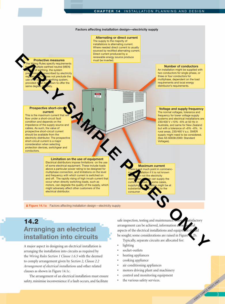
Protective measuresThe Wiring Rules specify requirements for the multiple earthed neutral (MEN) system of earthing, the system predominantly prescribed by electricity regulators. This does not preclude the use of an alternate earthing system, provided it can be shown to offer the same degree of safety.
Prospective short-circuit current
This is the maximum current that will flow under a short-circuit fault condition and depends on the impedance of the supply source and cables. As such, the value of prospective short-circuit current should be available from the electricity distributor. The prospective short-circuit current is a major consideration when selecting protection devices, switchgear and conductors.
Limitation on the use of equipmentElectrical distributors impose limitations on the use of some electrical equipment. These include loads above a particular power rating to be designed for multiphase connection, and limitations on the level and frequency with which current is switched on and off. The rapidly rising of high inrush current that occur when directly switching loads, such as motors, can degrade the quality of the supply, which might adversely affect other customers of the electrical distributor.
Maximum currentThere is not much point in commenc-ing an installation if it is not known whether or not the electricity distribution system can supply the current required. In some cases, supplying an installation might be at substantial additional cost to the consumer .
Voltage and supply frequencyThe normal voltages, tolerance and frequency for lower voltage supply systems and electrical installations are 230/400 V +10% –6% at 50 Hz in Australia, and same for New Zealand but with a tolerance of +6% –6%. In rural areas, 230/460 V a.c. SWER supply might need to be considered. (See AS 60038:2000: Standard Voltages).
Number of conductorsAn installation might be supplied with two conductors for single phase, or three or four conductors for multiphase, dependent on the load requirements and local energy distributor’s requirements.
Alternating or direct currentThe supply to the majority of installations is alternating current. Where needed direct current is usually sourced by rectified alternating current. Direct current produced by a renewable energy source produce must be inverted.
Figure 14.1a Factors affecting installation design—electricity supply
14.2 Arranging an electrical installation into circuitsA major aspect in designing an electrical installation is
arranging the installation into circuits as required by
the Wiring Rules Section 1 Clause 1.6.5 with the deemed
to comply arrangement given by Section 2, Clause 2.2
Arrangement of electrical installations and other related
clauses as shown in Figure 14.1c.
The arrangement of an electrical installation must ensure
safety, minimise inconvenience if a fault occurs, and facilitate
safe inspection, testing and maintenance. Before a satisfactory
arrangement can be achieved, information about several
aspects of the electrical installations and equipment should
be sought; some considerations are raised in Figure 14.2b.
Typically, separate circuits are allocated for:
• lighting
• socket-outlets
• heating appliances
• cooking appliance
• air conditioning appliances
• motors driving plant and machinery
• control and monitoring equipment
• the various safety services.
EARLY SAMPLE PAGES O
NLY
pet86436_ch14_001-046.indd 3 9/27/11 6:59 PM
EARLY SAMPLE PAGES ONLY
E L E C T R I C A L W I R I N G P R A C T I C E — V O L U M E 2
4
Factors affecting installation design—installation aspects
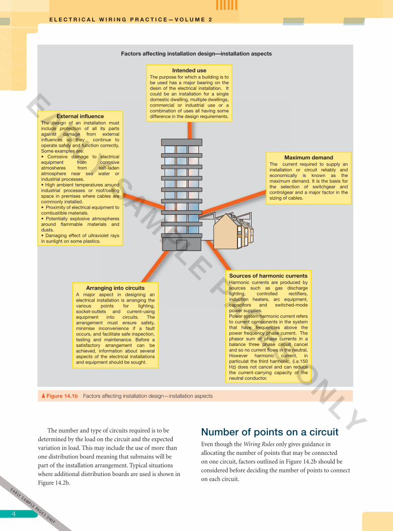
External influenceThe design of an installation must include protection of all its parts against damage from external influences so they continue to operate safely and function correctly. Some examples are:• Corrosive damage to electrical equipment from corrosive atmosheres from salt-laden atmosphere near sea water or industrial processes.• High ambient temperatures around industrial processes or roof/ceiling space in premises where cables are commonly installed.• Proximity of electrical equipment to combustible materials.• Potentially explosive atmospheres around flammable materials and dusts.• Damaging effect of ultraviolet rays in sunlight on some plastics.
Intended useThe purpose for which a building is to be used has a major bearing on the desin of the electrical installation. It could be an installation for a single domestic dwelling, multiple dwellings, commercial or industrial use or a combination of uses all having some difference in the design requirements.
Maximum demandThe current required to supply an installation or circuit reliably and economically is known as the maximum demand. It is the basis for the selection of switchgear and controlgear and a major factor in the sizing of cables.
Sources of harmonic currentsHarmonic currents are produced by sources such as gas discharge lighting, controlled rectifiers, induction heaters, arc equipment, capacitors and switched-mode power supplies.Power system harmonic current refers to current components in the system that have frequencies above the power frequency phase current. The phasor sum of phase currents in a balance three phase circuit cancel and so no current flows in the neutral. However harmonic current, in particulat the third harmonic, (i.e.150 Hz) does not cancel and can reduce the current-carrying capacity of the neutral conductor.
Arranging into circuitsA major aspect in designing an electrical installation is arranging the various points for lighting, socket-outlets and current-using equipment into circuits. The arrangement must ensure safety, minimise inconvenience if a fault occurs, and facilitate safe inspection, testing and maintenance. Before a satisfactory arrangement can be achieved, information about several aspects of the electrical installations and equipment should be sought.
Figure 14.1b Factors affecting installation design—installation aspects
The number and type of circuits required is to be
determined by the load on the circuit and the expected
variation in load. This may include the use of more than
one distribution board meaning that submains will be
part of the installation arrangement. Typical situations
where additional distribution boards are used is shown in
Figure 14.2b.
Number of points on a circuit Even though the Wiring Rules only gives guidance in
allocating the number of points that may be connected
on one circuit, factors outlined in Figure 14.2b should be
considered before deciding the number of points to connect
on each circuit.
EARLY SAMPLE PAGES ONLY
pet86436_ch14_001-046.indd 4 9/27/11 6:59 PM
EARLY SAMPLE PAGES ONLY

5
C H A P T E R 1 4 I N S T A L L A T I O N P L A N N I N G A N D D E S I G N
Maximum demand being the continuous current needed to
reliably and economically supply an installation or circuit.
In-coming consumers mains
Out-going circuits
3.2 TYPES OF WIRING SYSTEMS
3.3 EXTERNAL INFLUENCES
3.4 CURRENT-CARRYING CAPACITY
3.6 VOLTAGE DROP
3.4.4 Coordination between conductors and
protective devices
APPENDIX CCIRCUIT ARRANGEMENTS
Appendix C Paragraph C3 provides a set of current ratings that may be assigned to circuits in typical simple installations as an alternative to AS/NZS 3008.1 series.
AS/NZS 3008.1 SERIES—THE PRIMARY CABLE SELECTION
STANDARDAS/NZS 3008.1.1 is for Australianconditions—ambient temperatureof 40 °C
AS/NZS 3008.1.2 is for New Zealandconditions—ambient temperatureof 30 °C
Maximum demand being the
Lists acceptable methods for determining
maximum demand;
Refers to Section 3 for selection
and installation of conductors
Describes operating characteristics by which
equipment shall be selected and installed.In-coming consumers mains
Specifies requirement for electrical installation to be
divided into circuits;
g g
Clauses 2.4 to 2.8 specify requirements for electrical
protection (Chapter 10)
Clause 2.9 specify requirements for
switchboards (Chapter 13)
Switchboard
SECTION 3—SELECTION AND INSTALLATION OF WIRING SYSTEMS
2.2 ARRANGEMENT OF ELECTRICAL INSTALLATION
SECTION 2—GENERAL ARRANGEMENT, CONTROL AND PROTECTION
Figure 14.1c Relationship of Wiring Rules clauses and selection standards
EARLY SAMPLE PAGES O
NLY
pet86436_ch14_001-046.indd 5 9/27/11 6:59 PM
EARLY SAMPLE PAGES ONLY

E L E C T R I C A L W I R I N G P R A C T I C E — V O L U M E 2
6
STANDARDS Australia
N E W Z E A L A N DP A E R E W A A O T E A R O A
SECTION 1 SCOPE AND APPLICATION• Outlines the extent of cable selection covered by the Standard• Explains where the Standard is applied• Suggests other documents that can be used for cables and installation methods not covered by the Standard• List of reference and related documents SECTION 2 CABLE SELECTION
PROCEDURE• Outline the cable selection process• Describes the three consideration when determining the minimum cable size.• These considerations are detailed in in Sections 3, 4 and 5 of the Standard.
SECTION 3 CURRENT-CARRYING CAPACITY
• Covers the factors that effect current carrying capacity and therefore conductor size.• Contains selection tables of current-carrying capacity for given cable sizes.
EXPLANATION OF THESE FACTORS AND TABLES AND HOW TO APPLY THEM IS GIVEN IN SECTION14.3OF THIS VOLUME
SECTION 5 SHORT-CIRCUITPERFORMANCE
Explains the effects of high temperature of cable under a short-circuit and how to select cables based on maximum permitted short-circuit temperature.
A BRIEF EXPLANATION OF CABLES BASED ON SHORT-CIRCUIT PERFORMANCE IS GIVEN IN SECTION 14.3 OF THIS VOLUME.
APPENDICESA. Examples of cable selectionB. List of tablesC. Examples of reduction factors for harmonic currentsD. Recommended configurations for single-core cables in parallel
SECTION 4 VOLTAGE DROP• Descibe the various ways for determining voltage drop• Contains tables of resistance/ reactance values of commonly used cables for calculating voltage drop
EXPLANATION OF THE TABLES AND HOW THEY APPLY IN DETERMINING VOLTAGE DROP IS GIVEN IN SECTION 14.3 OF THIS VOLUME
Figure 14.1d Overview of AS/NZS3008.1
Irrespective of the number of circuits and the number
of points connected on one circuit, the requirement for
protection and safety must be met. In other words, the
rating of the circuit protection device must not be greater
than the current-carrying capacity of the cable, and the
current-carrying capacity of the cable must be suffi cient
to supply the load under the expected normal operating
conditions.
EARLY SAMPLE PAGES ONLY
pet86436_ch14_001-046.indd 6 9/27/11 6:59 PM
EARLY SAMPLE PAGES ONLY
7
C H A P T E R 1 4 I N S T A L L A T I O N P L A N N I N G A N D D E S I G N
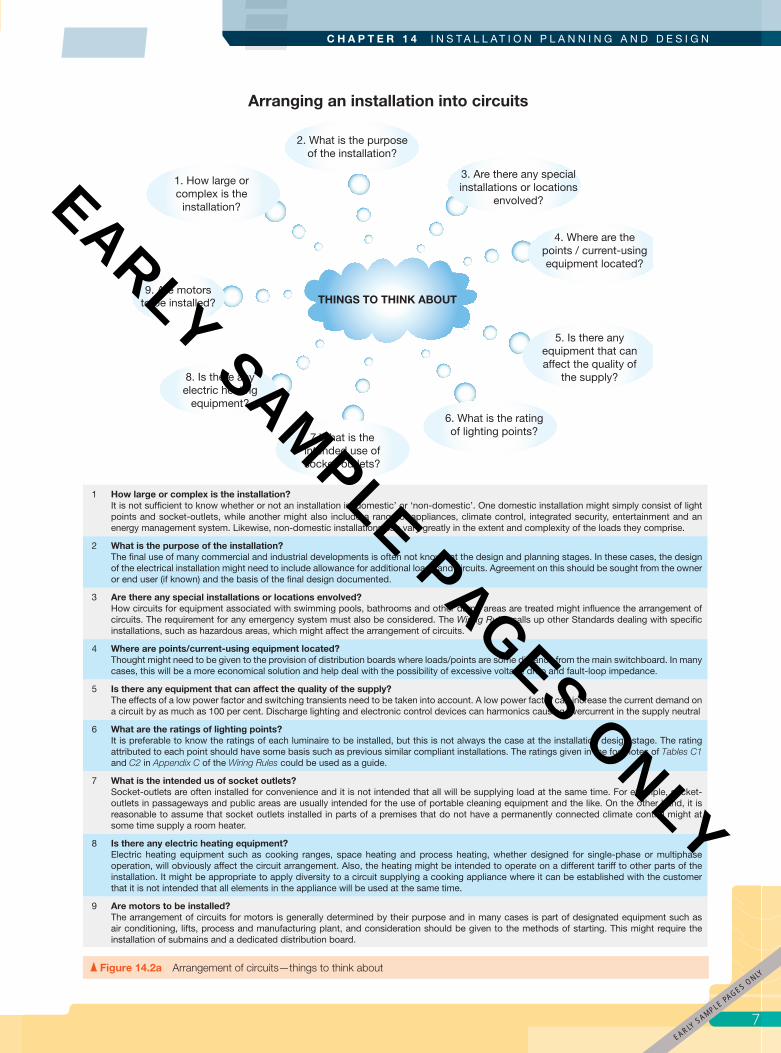
1 How large or complex is the installation?It is not sufficient to know whether or not an installation is ‘domestic’ or ‘non-domestic’. One domestic installation might simply consist of light points and socket-outlets, while another might also include a range of appliances, climate control, integrated security, entertainment and an energy management system. Likewise, non-domestic installations can vary greatly in the extent and complexity of the loads they comprise.
2 What is the purpose of the installation?The final use of many commercial and industrial developments is often not known at the design and planning stages. In these cases, the design of the electrical installation might need to include allowance for additional loads and circuits. Agreement on this should be sought from the owner or end user (if known) and the basis of the final design documented.
3 Are there any special installations or locations envolved?How circuits for equipment associated with swimming pools, bathrooms and other damp areas are treated might influence the arrangement of circuits. The requirement for any emergency system must also be considered. The Wiring Rules calls up other Standards dealing with specific installations, such as hazardous areas, which might affect the arrangement of circuits.
4 Where are points/current-using equipment located?Thought might need to be given to the provision of distribution boards where loads/points are some distance from the main switchboard. In many cases, this will be a more economical solution and help deal with the possibility of excessive voltage drop and fault-loop impedance.
5 Is there any equipment that can affect the quality of the supply?The effects of a low power factor and switching transients need to be taken into account. A low power factor can increase the current demand on a circuit by as much as 100 per cent. Discharge lighting and electronic control devices can harmonics causing overcurrent in the supply neutral
6 What are the ratings of lighting points?It is preferable to know the ratings of each luminaire to be installed, but this is not always the case at the installation design stage. The rating attributed to each point should have some basis such as previous similar compliant installations. The ratings given in the footnotes of Tables C1 and C2 in Appendix C of the Wiring Rules could be used as a guide.
7 What is the intended us of socket outlets?Socket-outlets are often installed for convenience and it is not intended that all will be supplying load at the same time. For example, socket-outlets in passageways and public areas are usually intended for the use of portable cleaning equipment and the like. On the other hand, it is reasonable to assume that socket outlets installed in parts of a premises that do not have a permanently connected climate control might at some time supply a room heater.
8 Is there any electric heating equipment?Electric heating equipment such as cooking ranges, space heating and process heating, whether designed for single-phase or multiphase operation, will obviously affect the circuit arrangement. Also, the heating might be intended to operate on a different tariff to other parts of the installation. It might be appropriate to apply diversity to a circuit supplying a cooking appliance where it can be established with the customer that it is not intended that all elements in the appliance will be used at the same time.
9 Are motors to be installed? The arrangement of circuits for motors is generally determined by their purpose and in many cases is part of designated equipment such as air conditioning, lifts, process and manufacturing plant, and consideration should be given to the methods of starting. This might require the installation of submains and a dedicated distribution board.
Arranging an installation into circuits
1. How large or complex is the
installation?
2. What is the purpose of the installation?
3. Are there any special installations or locations
envolved?
4. Where are the points / current-using equipment located?
6. What is the rating of lighting points?
5. Is there any equipment that can affect the quality of
the supply?
7.What is the intended use of socket-outlets?
8. Is there any electric heating
equipment?
9. Are motors to be installed? THINGS TO THINK ABOUT
Figure 14.2a Arrangement of circuits—things to think about
EARLY SAMPLE PAGES O
NLY
pet86436_ch14_001-046.indd 7 9/27/11 6:59 PM
EARLY SAMPLE PAGES ONLY

E L E C T R I C A L W I R I N G P R A C T I C E — V O L U M E 2
8
Use Table C8 in Appendix C of the Wiring Rules for guidance on the current allocation of each item on a circuit.
Designed each circuit so that small overloads of long duration do not frequently occur; frequent overloading of circuit conductors can deteriorate the cable and reduce the life of the insulation
Limit the number of socket-outlet on a circuit intended for fixed Class I appliances, such as washing machines, to avoid nuisance tripping of RCDs from standing leakage currents
Avoid connecting all socket-outlets intended for the supply of high-demand appliances on the one circuit
Provide a separate circuit for items of equipment that have essen-tial functions such as security and emergency services
Provide a separate circuit for each item of equipment that has a current rating greater that 20 A per phase
Allow the number of circuits sufficient to ensure that maintenance can be carried out with minimum inconvenience
Electric heating
Socket outlets
Electrical machines
Cooking appliances
Lighting
Appliances (white goods)
Figure 14.2b Using more than one switchboard—typical situations
DID YOU KNOW?
Manufacturing standards allow an RCD with a rated tripping current of 30 mA a tolerance of ± 7.5 mA while standards for class one appliance permit a standing leakage current not exceed 5 mA. So too many such appliances connected to one circuit will likely cause nuisance tripping.
14.3 Factors affecting cable selection Once the arrangement of circuits is decided the cables for
each circuit are selected. Before this can be done a number
of interrelated factors must be well thought-out. Apart from
the economic aspects the installation designer must take
into account the current requirements of the installation
and circuits (Maximum demand), external infl uences, EARLY SAMPLE PAGES ONLY
pet86436_ch14_001-046.indd 8 9/27/11 6:59 PM
EARLY SAMPLE PAGES ONLY
9
C H A P T E R 1 4 I N S T A L L A T I O N P L A N N I N G A N D D E S I G N
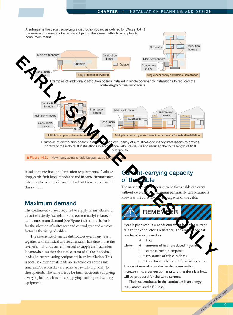
A submain is the circuit supplying a distribution board as defined by Clause 1.4.41 the maximum demand of which is subject to the same methods as applies to consumers mains.
Examples of additional distribution boards installed in single occupancy installations to reduced the route length of final subcircuits
Examples of distribution boards installed in each occupancy of a multiple-occupancy installations to provide control of the individual installations in accordance with Clause 2.3 and reduced the route length of final
subcircuits.
Single domestic dwelling
Main switchboard Distributionboard
Distributionboards
Submain
Submains
Consumersmains
Consumersmains
Single occupancy commercial installation
Main switchboard
Garage
Main switchboard
Consumersmains
Consumersmains
Multiple occupancy domestic installation Multiple occupancy non-domestic /commercial/industrial installation
Submains
Submains
Distributionboards
Distributionboards
Distributionboards
Main switchboard
Figure 14.2c How many points should be connected to one circuit?
installation methods and limitation requirements of voltage
drop, earth-fault loop impedance and in some circumstance
cable short-circuit performance. Each of these is discussed in
this section.
Maximum demand The continuous current required to supply an installation or
circuit effectively (i.e. reliably and economically) is known
as the maximum demand (see Figure 14.3a). It is the basis
for the selection of switchgear and control gear and a major
factor in the sizing of cables.
The experience of energy distributors over many years,
together with statistical and fi eld research, has shown that the
level of continuous current needed to supply an installation
is somewhat less than the total current of all the individual
loads (i.e. current-using equipment) in an installation. This
is because either not all loads are switched on at the same
time, and/or when they are, some are switched on only for
short periods. The same is true for fi nal subcircuits supplying
a varying load, such as those supplying cooking and welding
equipment.
Current-carrying capacity of the cableThe maximum continuous current that a cable can carry
without exceeding its maximum permissible temperature is
known as the current-carrying capacity of the cable.
REMEMBER
Heat is produced in a conductor when it carries current due to the conductor’s resistance. The amount of heat produced is expressed as: H � I2Rtwhere H � amount of heat produced in joules I � cable current in amperes R � resistance of cable in ohms t � time for which current fl ows in seconds.The resistance of a conductor decreases with an increase in its cross-section area and therefore less heat will be produced for the same current.
The heat produced in the conductor is an energy loss, known as the I2R loss.
EARLY SAMPLE PAGES O
NLY
pet86436_ch14_001-046.indd 9 9/27/11 6:59 PM
EARLY SAMPLE PAGES ONLY

E L E C T R I C A L W I R I N G P R A C T I C E — V O L U M E 2
10
Maximum demandThe continuous current required to supply an installation or circuit reliably and economically is known as the maximun demand for that installation of circuit.
Factors having a bearing on the maximum demand • The duty cycle of loads; that is, the duration and times of day they are used;• How local climatic conditions affect the use of heating and cooling loads;• The duty rating and power demand of loads such as motors;• The purpose of the premises; for example, single or multiple residence, hotel, hospital, commercial, manufacturing facility;• Supply arrangements;• Possibility for growth in demand; and • Local conditions such as extremes in ambient temperature.
kWh
Main Switchboard
Distribution BoardMaximum demand in consumer mains and submains
The calculation method for determining maximum demand is the method most commonly used. In this method, demand calculations are classified in Appendic C of the Wiring Rules as:• single and multiple domestic installations (Paragraph C2.3 and Table C1); and • two categories of non-domestic installations (Paragraph C2.4 and Table C2);The calcualted maximum demand per phase is the sum of the currents allocated for each load group given in Tables C1 and C2.Alternatively, for non domestic installations the maximum demand can calculated from the sum of the energy per square metre of floor area allocated to each load group given in Table C3
Consumers main
Submain
Final subcircuits
Maximun demand in final subcircuitsThe maximum demand of final subcircuits is generally straightforward being the connected load or usually limited by the rating of the protective device. (Paragraph C2.5.) However a diversity allowances may be applied to final subcircuits supplying welding machines and domestic cooking appliance.
Minimum current-carrying capacity is based on the
maximum demand
Minimum current-carrying capacity is based on the maximum demand
Point of attachment /entry (Clause 1.4.73 and 1.4.74)
Minimum current-carrying capacity is based on the
maximum demand
Figure 14.3a About maximum demand
For a given maximum demand and cable type the factors
that affect the minimum conductor size needed to carry the
current (current-carrying capacity) are:
• ambient temperature
• cables installed unenclosed, enclosed and/or in thermal
insulation
• cable installed in direct sunlight
• grouping of cables
• cables installed in ground
• harmonic current.
These factors are explained in Figures 14.3b-2 to 6.
Cables installed in the groundThe maximum current-carrying capacity of cables installed in the ground, whether directly or in an underground enclosure, is slightly less than the same cable installed spaced in air. Derating/rating factors for cable installed in ground applicable to variations in ambient temperature and grouping of cables have been shown in Figures 14.3b-2 and 5. However the two other factors that must be applied are the depth at which cables are laid and thermal resistivity of the soil as explained in Figure 14.3b-6.
ATTENTION
Derating/rating factors A derating factor is used where the condition to which it applies can result only in an increase cable size, like when cable are closely grouped. See AS/NZS 3008.1 Tables 21 to 26(2).
A rating factor is commonly used where the condition to which it applies can result in either an increase of decrease in cable size, like ambient temperature. See AS/NZS 3008.1 Tables 27(1) to 28. Applying a de-rating/rating factor:
IC �
IMD ___ k
Where: IC is the minimum current carrying capacity
for the cable I
MD is the maximum demand for the circuit, and
k is the de-rating/rating factor Applying more than one de-rating/rating factor to a
cable:
IC �
IMD __________ k1 � k2 � etc
1
EARLY SAMPLE PAGES ONLY
pet86436_ch14_001-046.indd 10 9/27/11 6:59 PM
EARLY SAMPLE PAGES ONLY

11
C H A P T E R 1 4 I N S T A L L A T I O N P L A N N I N G A N D D E S I G N
Figure 14.3b-1 Features of a cable that limit its current-carrying capacity
I2R loss in the conductor
The structural features of a cable that limit its current-carrying capacity
1. Copper has a much lower resistance than aluminium and therefore has a higher current-carrying capacity for a given conductor size.
2. The maximum permitted conductor temperature for common polymeric insulation types is:
2. Cable insulation/sheath type which limits maximum conductor temperature
1. Conuctor size and conductor material
Tempurature of the conductor increases as current increases
A maximum operatining temperatures of 250 ° C is permitted for bare-metal sheaths under conditions
given in Note 7 Table 1 of AS/NZS 3008.1.
The maximum permitted operating temperature is 100 °C for external sheath or serving.
150
110
90
75
°C
insulant types 150 fibrous or polymeric
insulants types R-HF-110, R-E-110, X-HF-110
insulants types X-90, X-HF-90, R-EP-90,R-HF-90,RCSP-90;
thermoplastic insulant.
Mineral insulated metal sheathed (MIMS) cable
Effects of harmonics on balance three-phase systems Power system harmonics are voltage or current components
in the system that have frequencies above the fundamental
supply frequency. The most harmful being the 3rd
harmonic i.e. 150 Hz (3 � 50 Hz) as it can cause overheating
line and neutral conductors as shown in Figure 14.3b-7.
Higher order harmonic (e.g. 9th and 12th) may also cause
overheating if more than 10% of content of the phase
current.
Varying loadThe heating effect of a current is due to some average
current value. Advantage may be taken of this when
determining the maximum demand of a circuit, which
in turn usually determines the current-carrying capacity
of the circuit cables. For example, if a duty cycle can be
established, an equivalent steady current can be determined
under specifi c design (Wiring Rules, Clause 1.9.4). Similarly,
Appendix C of the Rules, Paragraph C2.5 provides criteria for
the duty cycles of welding machines.
EARLY SAMPLE PAGES O
NLY
pet86436_ch14_001-046.indd 11 9/27/11 6:59 PM
EARLY SAMPLE PAGES ONLY

E L E C T R I C A L W I R I N G P R A C T I C E — V O L U M E 2
12
40
30
25
15
°C
Australian air temperature AS/NZS 3008.1.1
New Zealand air temperature AS/NZS 3008.1.2
Australian soil temperature AS/NZS 3008.1.1
New Zealand soil temperature AS/NZS 3008.1.2
The ambient temperature base, for the current-carrying capacities of AS/NZS 3008.1 series
Tem
per
atur
e
Current
For a given current the final temperature of
a cable rises above its initial temperature
The temperature rise is nearly a constant
(for a given current) within the temperature
ranges we are dealing with.
Ambient or initial temperature
The higher the ambient or initial temperature, the higher the final
temperature of the cable
Ambient temperature Effects of ambient temperature
Where it could be shown that the prevailing ambient temperature in a particular locality in Australia is 30 ºC or less, then it would be justifiable to use the current values given for New Zealand conditions in AS/NZS 3008.1.2. The reverse could be applied in New Zealand.
The notes in Clause 3.5.3 of AS/NZS 3008.1 series explain some installation conditions that can affect ambient temperature and might result in a de-rating or up-rating of the cable’s current-carrying capacity.
STANDARDS Australia
N E W Z E A L A N DP A E R E W A A O T E A R O A
Lower ambient temperatures increase
current carrying capacity making a smaller
conductor size possible
Higher ambient temperatures decrease
current carrying capacity making a larger
conductor size likely
Lower ambient temperatures increase
current carrying capacity making a smaller
conductor size possible
Higher ambient temperatures decrease
current carrying capacity making a larger
conductor size likely
The following shows an extracted from Table 27(1) AS/NZS 3008.1.1 giving ambient temperature rating factors for cables in air or heated concrete slabs for Australian conditions. The same tables in AS/NZS 3008.1.2 give rating factors for New Zealand conditions.
The following shows an extracted from Table 27(2) AS/NZS 3008.1.1 giving ambient temperature rating factors for cables buried direct in ground or in underground wiring enclosures for Australian conditions. The same tables in AS/NZS 3008.1.2 give rating factors for New Zealand conditions.
Figure 14.3b-2 Effects of ambient temperature
1
EARLY SAMPLE PAGES ONLY
pet86436_ch14_001-046.indd 12 9/27/11 6:59 PM
EARLY SAMPLE PAGES ONLY

13
C H A P T E R 1 4 I N S T A L L A T I O N P L A N N I N G A N D D E S I G N
F14.3b-3
The example are extracted from Table 10 (AS/NZS 3008.1.1) showing the current-carrying capacity of 2.5mm2 two-core sheathed cable with thermoplastic insulation (75°C)
The effect of installation conditions and example of how the resulting current-carrying capacity is shown in tables
in AS/NZS 3008.1
Cable installed in air fixed to a continuous surface
Restricted heat dissipation
Heat dissipation from the cable is partcially restricted slightly reducing its current-carrying capacity
Heat dissipates is somewhat restricted being first internally in the enclosure and in turn from the enclosure reducing the current-carrying capacity to � 80% of the unrestricted value.
Internal heat dissipation
Heat dissipation from the enclosure
Cable installed in an enclosure
Cable installed in air spaced from a surface Heat dissipation
Cable tray or ladder
Heat dissipation from the cable is unrestricted allowing the cable to carry maximum current for its temperature rating.
Maximum current-carrying capacity for ambient temperature of 40 °C
Note.Bulk thermal insulation such as fibreglass ‘batts’ is used to improve the energy efficiency of buildings.
Cable partially surrounded by bulk thermal insulation
Severely restricted heat dissipation
Heat dissipation from the cable is severely restricted reducing its current-carrying capacity to � 75% of the unrestricted value.
Cable totally surrounded by bulk thermal insulation
Very little heat dissipation Little heat can dissipate from
the cable reducing its current-carrying capacity to � 50% of the unrestricted value.
Note the dramatic reduction in current-carrying capacity compared
with a cable spaced in air
Figure 14.3b-3 Effects of installation conditions
3EARLY
SAMPLE PAGES ONLY
pet86436_ch14_001-046.indd 13 9/27/11 6:59 PM
EARLY SAMPLE PAGES ONLY
E L E C T R I C A L W I R I N G P R A C T I C E — V O L U M E 2
14
As explained in Clause 3.5.6 of AS/NZS 3008.1, the
current-carrying capacities and de-rating factors given are
based on continuous loading conditions on all conductors.
Up-rating factors may be applied where intermittent or cyclic
load variations occur or where all conductors cannot be
loaded simultaneously.
Other up-rating factors include low ambient temperature
conditions and use of a cable to supply a continuous load
below the cable’s rated current-carrying capacity. The use of
an alternative de-rating factor to those published in Tables
22 to 26(2) of AS/NZS 3008.1 may be justifi ed where there is
a mixture of loaded and unloaded cables and the connected
loads have a known diversity, or where there is a known cycle
or shape for a daily load pattern.
The current carrying capacity of all common types of
cables and derating and rating factors are given in the tables
of Section 3 of AS/NZS 3008.1 as shown in fi gure 14.3d
Voltage drop and earth fault-loop limitationBoth voltage drop and earth fault-loop impedance limit the
maximum route length of a circuit for given conductor size
load current and protective device. Clauses 1.6.4 and 3.6 of
the Wiring Rules limit voltage drop to 5 % for an
installation; in extra-low-voltage (ELV) circuits, it is
10 per cent. This is the voltage drop across the series
arrangement of circuits in the installation from the point
of supply to the furthest current-using device or point in
each fi nal subcircuit, as shown in Figure 14.3e-1.
Recalling the that voltage drop is proportional to both
current and resistance; that is:
V � IR,
and resistance is proportional to resistivity of the conductor
material (i.e. copper or aluminium) and conductor length
and inversely proportional to its cross-sectional area (csa),
that is;
R • � L/A
Applied to the voltage drops in an installation;
V is the voltage drop across the conductor
I is the current carried by the conductor
R is the resistance of the conductor, and
� is the resistivity of the conductor material
(Cu 1.72 � 108; Al 2.83 � 108)
L is the length of the conductor
A is the csa of the conductor
The foregoing shows that the factors to considered
when selecting cables to meet voltage drop limits are the
load current; the conductor size and route length of a
circuit.
A cables (in a series group) selected for a installation
may satisfy their current-carrying requirements, however,
the resistance of the cable might be too high due to the
length of the cable runs to meet voltage drop limitations.
In this case, the cable size (cross-sectional area) of one
or more cables (in the series group) will need to be
increased.
The earth fault-loop impedance (EFLI) is the impedance
of the conductors in the series path taken by the current
in the event of a fault between an active conductor and an
earth. As discussed in Chapter 8, the earth fault-loop is made
up of the distribution transformer and supply conductors
external to the installation, and the active and protective
earthing conductors within the installation. The impedance
of the earth fault-loop, in most cases majority of which is
resistance, must be suffi ciently low to:
• allow enough current to fl ow to operate the protective
device and disconnect the supply in a prescribed time
• therefore limit the rise in touch voltage as required by
the Wiring Rules, Clauses 1.5.5.3 and 2.4.2.
Note that additional explanations of touch voltage is
given in Appendix B, Paragraph B4 of the Wiring Rules.
The focus here in selecting cables is the internal EFLI as
reviewed in Figure 14.3e-2.
In a similar way to voltage drop EFLI is dependant
the cable resistance, in this case the size (csa) of the active
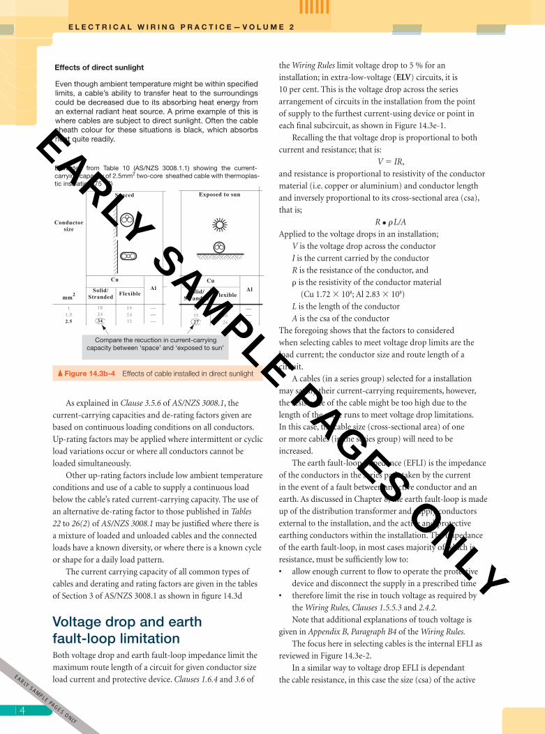
Even though ambient temperature might be within specified limits, a cable’s ability to transfer heat to the surroundings could be decreased due to its absorbing heat energy from an external radiant heat source. A prime example of this is where cables are subject to direct sunlight. Often the cable sheath colour for these situations is black, which absorbs heat quite readily.
Effects of direct sunlight
FlexibleSolid/Stranded
Al
Cu
151927
162026
Exposed to sun
Extracted from Table 10 (AS/NZS 3008.1.1) showing the current-carrying capacity of 2.5mm2 two-core sheathed cable with thermoplas-tic insulation (75 °C)
Compare the recuction in current-carrying capacity between ‘space’ and ‘exposed to sun’
Figure 14.3b-4 Effects of cable installed in direct sunlight
1
EARLY SAMPLE PAGES ONLY
pet86436_ch14_001-046.indd 14 9/27/11 6:59 PM
EARLY SAMPLE PAGES ONLY

15
C H A P T E R 1 4 I N S T A L L A T I O N P L A N N I N G A N D D E S I G N
The effect of cables of more than one circuit installed in groups
Cables of more than one circuit suitably spaced
In these examples of cables installed in ground and in air de-rating of cables due to grouping is avoided by installing cables with sufficient clearances to prevent mutual heating.
Mutual heating between cables installed touching and restricted
air movement
Mutual heating between cables and restricted air movement
within the enclosures
The ability of a cable to dissipate heat to the surrounding environment is reduced when it is installed in contact with cables of other circuits. Grouping cables inhibits the free circulation of air around each cable and promotes the mutual heating of the cables in the group.Derating of cables effectively increases conductor size required.
This example is extracted from Tables 24 (AS/NZS 3008.1.1)showing the derating factor for circuits of multcore cables installedon supports in air.
In this example of the circuits conductors are increase two sizes, e.g. from 2.5 mm2 to 6.00 mm2
This example is extracted from Tables 22 (AS/NZS 3008.1.1) showing the derating factor for bunched circuits of single and multcore cables.
In the example of the circuits installed in conduit the conductors are increase one size, e.g. from 2.5 mm2 to 4.00 mm2
In the example of the circuits installed in trunking the conductors are increase two sizes, e.g. from 2.5 mm2 to 6.00 mm2
TABLES 25(1) TO 26(2)DERATING FACTORS FOR GROUPING OF CIRCUITSBURIED DIRECT; IN UNDERGROUND ENCLOSURES
SECTION 3 CURRENT-CARRYING CAPACITY
3.5 EXTERNAL INFLUENCES ON CABLES 3.5.2 Effects of grouping ofcables 3.5.2.2 Installation conditions that avoid derating
Figure 1 MINIMUM CABLE SPACING IN AIR TO AVOID DERATING
3.5.2.5 Cables buried direct in ground 3.5.2.6 Cables installed in underground enclosures
Heat is dissipated by the air free to circulate around each cable when spaced
as specified in AS/NZS3008.1 Figure 1
� 2.00 m � 2.00 m
Mutual heating is avoided by this minimum spacing
Figure 14.3b-5 Effects of grouping of cables
5EARLY
SAMPLE PAGES ONLY
pet86436_ch14_001-046.indd 15 9/27/11 6:59 PM
EARLY SAMPLE PAGES ONLY
E L E C T R I C A L W I R I N G P R A C T I C E — V O L U M E 2
16
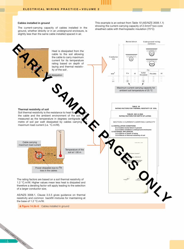
Cables installed in ground
The current-carrying capacity of cables installed in the ground, whether directly or in an underground enclosure, is slightly less than the same cable installed spaced in air.
Maximum current-carrying capacity for ambient soil temperature of 25 °C
This example is an extract from Table 10 (AS/NZS 3008.1.1) showing the current-carrying capacity of 2.5mm2 two-core sheathed cable with thermoplastic insulation (75°C)
TABLE 29RATING FACTORS FOR THERMAL REISTIVITY OF SOIL
TABLES 28(1) & 28(2)RATING FACTORS FOR DEPTH OF LAYING
SECTION 3 CURRENT-CARRYING CAPACITY
3.4 INSTALLATION CONDITIONS 3.4.4 Cables buried direct in ground 3.4.5 Cables installed in underground enclosures3.5 EXTERNAL INFLUENCES 3.5.4 Effects of depth of laying 3.5.5 Effects of thermal resistivity of soil
Heat is dissipated from the cable to the soil allowing the cable to carry maximum current for its temperature rating based on depth of laying and thermal resistiv-ity of the soil .
Heat dissipation
Dep
th
Thermal resistivity of soilSoil thermal resistivity is the resistance to heat flow between the cable and the ambient environment of the soil. It is measured as the temperature in degrees centigrade for a metre of soil per watt dissipated by cables carrying the maximum load current (i.e. °C.m/W).
1.00 m
°C
Power disipated due to I2R loss in the cables
Temperature of the soil at 1.00 m
Cable carrying maximum load current
The rating factors are based on a soil thermal resistivity of1.2 °C.m/W. Higher values mean less heat is disipated and therefore a derating factor will apply leading to the selection of a larger conductor size. AS/NZS 3008.1, Clause 3.5.5 gives guidance on thermal resistivity and common backfill mixtures for maintaining at the base of 1.2 °C.m/W.
Figure 14.3b-6 Cables installed in ground
1
EARLY SAMPLE PAGES ONLY
pet86436_ch14_001-046.indd 16 9/27/11 6:59 PM
EARLY SAMPLE PAGES ONLY

17
C H A P T E R 1 4 I N S T A L L A T I O N P L A N N I N G A N D D E S I G N
Figure 14.3c How harmonic current can cause overheating of line and neutral conductors
Nonlinear load
Nonlinear load
Nonlinear load
IN (150 Hz) = IA (150 Hz) + IB (150 Hz) + I3 (150 Hz)
IA (150Hz )IA (50 Hz)
IB (150Hz )IB (50 Hz)
IC (150Hz )IC (50 Hz)
Being a balance system IN (50 Hz) ≈ 0
How harmonic current can cause overheating of line and neutral conductor
120° 120° 120°
Third order harmonic produced in each phase are shown off-set to illustrate that they are in-phase although their fundamentals (50 Hz) are each shifted 120°.
The resulting neutral current is the arithmatical sum of the phase harmonic currents: IN (150 Hz) = IA (150 Hz) + IB (150 Hz) + I3 (150 Hz)
Each phases in the three-phase 50 Hz supply is shifted by 120° 12
0°
120°
120°
Fundamental 50 Hz supply
1 2 3
Note that the 3rd order harmonic has three cycles for ever one cycle of the fundamental
Third order harmonic produced in a nonlinear load.
Clause 3.5.2 of the Wiring Rules specify criteria for the current-carry capacity of neutral conductors. The cable selection standard AS/NZS 30081, Clause 3.5.9 and Table 2, specify reduction factors that apply to 4-core and 5-core cables where the third-harmonic content of phase current is greater that 15%. Examples of how these reduction factor are applied are given in Appendix D of the standard.
Harmonics are produced in nonlinear components of loads such as gas discharge lighting banks, variable speed drive, soft starters, controlled rectifiers, induction heaters, arc equipment, and switched-mode power supplies. The resulting distortion of the supply waveform not only causes overheating of cables but reduces power factor, makes reading of revenue meters inaccurate and increases heat in transformer, motors and generators.
The harmonic content of a load devices should be obtainable from manufacturers. In many cases where harmonics is a significant problem, filters are used to mitigate their effects.
7EARLY
SAMPLE PAGES ONLY
pet86436_ch14_001-046.indd 17 9/27/11 6:59 PM
EARLY SAMPLE PAGES ONLY
E L E C T R I C A L W I R I N G P R A C T I C E — V O L U M E 2
18
SECTION 1 SCOPE AND APPLICATION
SECTION 2 CABLE SELECTION PROCEDURE
SECTION 3 CURRENT-CARRYING CAPACITY
SECTION 4 VOLTAGE DROP SECTION 5 SHORT-CIRCUIT PERFORMANCE
APPENDICES(Examples and circuit configurations)
STANDARDS Australia
N E W Z E A L A N DP A E R E W A A O T E A R O A
TABLE 3(1)
TABLE 3(2)
TABLE 3(3)
TABLE 3(4)
Unenclosed
Enclosed
Buried direct
Enclosedunderground
INSTALLATION METHODProvides direction to current-carrying
capacity and derating tables
CURRENY-CARRYING CAPACITY TABLES
TABLE 4
TABLE 7
TABLE 10
TABLE 13
2 x single-core
3 x single-core
Two-core
Three-core and four-core
Thermoplastic insulated (75 °C)
2 x single-core
3 x single-core
Two-core
Three-core and four-core
TABLE 5
TABLE 8
TABLE 11
TABLE 14
Cross-linked elastomericinsulation (90 °C)
2 x single-core
3 x single-core
Two-core
Three-core and four-core
TABLE 6
TABLE 9
TABLE 12
TABLE 15
Cross-linked polyolefin (XLPE)insulation (110 °C)
TABLE 18
TABLE 19
Bare single-core
Bare multicore
Mineral-insulated copper-sheathed (MIMS)Sheath temperature:110 °C
Flexible cords and cables
TABLE 16 60°C insulants
150°C insulantsTABLE 17
TABLE 20
TABLE 21
Copper conductors
Aluminium conductors
Aerial cables
DERATING/RATING TABLES
Single-core
Multicore
TABLE 25(1)
TABLE 25(2)
Buried direct in ground
Single-core enclosed separately
Multicore enclosed separately; more than one single-core per enclosure.
TABLE 26(1 )
TABLE 26(2)
In underground enclosures
TABLE 28(1)
TABLE 28(2)
Buried direct
In wiring enclosure
Variations in depth of laying
Variations in ambient temperature
TABLE 27(1) In air and concrete slabs
UndergroundTABLE 27(2)
TABLE 29 Buried direct and enclosed
Variations in the thermal resistivity of soil
Groups of circuits
TABLE 22
TABLE 23
TABLE 24
Bunched in air and enclosures
Single-core
Multicore
On cable tray, ladder . . .
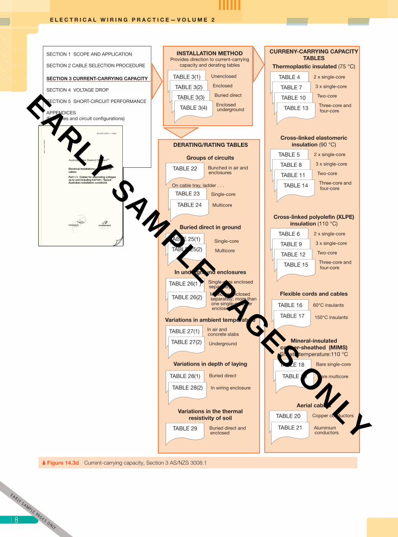
Figure 14.3d Current-carrying capacity, Section 3 AS/NZS 3008.1
1
EARLY SAMPLE PAGES ONLY
pet86436_ch14_001-046.indd 18 9/27/11 6:59 PM
EARLY SAMPLE PAGES ONLY

19
C H A P T E R 1 4 I N S T A L L A T I O N P L A N N I N G A N D D E S I G N
Figure 14.3e-1 Voltage drop across a series arrangement of circuits in an installation
Voltage drop across a series arrangement of circuits in an installtion
Nominal supply voltage (Vs) 230/400V
3M3
42
24
2
1M2
2
4
VV
2Point of supply
V
Vp ≤ 5% of Vs i.e.≤ 218.5/380 Volts
Vp ≤ 5% of Vs i.e.≤ 218.5/380 Volts
Main switchboard
Distribution board
Consumers mains
Submain
Finalsubcircuit HW
Consumers mains Submain
Vsm
Final subcircuit
Final subcircuit
HW
3M
Vfsc1
Vfsc2
Rfsc
Rfsc
Vcm
Rcm RsmPoS
Vd
Vd
Vd = Vcm + Vsm + Vfsc1
Vd = Vcm + Vsm + Vfsc2
Maximum permitted voltage drop Vp ≥ sum of voltage drops in a series group of circuits
Voltage drop limitation (Wiring Rules Clause 3.6) applies to any series arrangement of circuits in an installation such as the consumers main and a final subcircuit, or as shown below the consumers mains, a submains in series with two different final subcircuits.
Equivalent circuit
conductor and the protective earthing conductor and the
route length of the circuit. Given the previous discussion on
voltage drop, it is clear that the maximum route length of a
circuit must satisfy the limitation of both the earth fault-loop
impedance and voltage drop.
Of concern is that the route length of the cables selected
on the basis of voltage drop does not result in a fault-loop
impedance that is too high. Generally, cables for single-phase
that comply with the limits of voltage drop will, in most
instances, be within the limits of fault-loop impedance. This
does not mean that the integrity of the fault-loop impedance
for each circuit should not be verifi ed, because such checking
is an essential part of ensuring that the protective measures
required in an electrical installation will operate as intended.
Note that Wiring Rules Appendix B Paragraph B5 and
Table B1 provide information on the maximum length of
circuits—this only related to EFLI.
Relationship between cables and protective devices The purpose of assigning current-carrying capacities to
cables is to obtain the most economic use of cables and
at the same time ensure the continuing safe function of
the electrical installation. The previous discussion and
examples has shown that the current-carrying capacity
or rating of a cable varies depending on the conditions in
which it is installed. The particular ratings are assigned so
that maximum-permissible cable temperatures allowed
for the cable is not exceeded in normal use. If cables are
operated above their current-carrying capacity, insulation
will deteriorate, increasing the likelihood of insulation
breakdown and risk of injury to persons or damage to
property. For this reason, Clause 2.5.3.1 of the Wiring Rules
requires circuit conductors to be protected against overload.
9EARLY
SAMPLE PAGES ONLY
pet86436_ch14_001-046.indd 19 9/27/11 6:59 PM
EARLY SAMPLE PAGES ONLY

E L E C T R I C A L W I R I N G P R A C T I C E — V O L U M E 2
20
Earth fault-loop impedance
Earth fault-loop impedance
4
3M3
2
Ω
4
2
1M2
2
2
2
4
Ω
ΩΩEFLI
RA
Active conductor
RPE
Protective earth
Internal earth fault-loop impedance
Earth fault-loop impedance requirements (Wiring Rules Clauses 1.5.5.3; 2.4.2 and 5.7.4)) applies to all circuits in an installationThe factors affecting the earth fault-loop impedance are the resistance of the active and associated protective earthing conductors; that is, the conductor size and route length. The installation shown is the same as in Figure 14.3-1 for voltage drop emphasing that both voltage drop and EFLI limits must be satisfied.
Equivalent circuit
Figure 14.3e-2 Internal EFLI in an installation
The simultaneous operation of a number of appliances
on a circuit of socket-outlets or a motor with a mechanical
fault are typical examples that cause overloading of cables
(i.e. they have to carry current higher than their current-
carrying capacity).
The current required to trip a circuit breaker in the
conventional time is taken as 1.45 times its nominal current
rating, and for a fuse (complying with AS 2005 series),
the fusing current is 1.6 times its nominal current rating.
Therefore, where a fuse is used, it is de-rated to 90 per cent
(1.45/1.6) of its rated value. For example, a fuse with a
nominal current rating of 20 A becomes 18 A (20 � 0.9) for
purpose of providing overload protection.
The main point is that, when selecting cables for their
current-carrying capacity, consideration should also be
given to the protective device being used. The maximum
demand of final subcircuits can be regarded as the
nominal current rating of the circuit protective device.
This should be sufficient current to supply the load and
must not be greater than the current-carrying capacity of
the cables.
In addition to overload protection discussed here,
protection against indirect contact and short-circuit currents
must be provided. Protection and protective devices are
discussed in Chapter 10.
14.4 Determining maximum demandThe continuous current required to supply an installation or
circuit reliably and economically is known as the maximum demand. It is the basis for the selection of switchgear and
control gear and a major factor in the sizing of cables.
The experience of energy distributors over many years,
together with statistical and fi eld research, has shown that the
level of continuous current needed to supply an installation
is somewhat less than the total current of all the individual
loads (i.e. current-using equipment) in an installation. This
is because either not all loads are switched on at the same
time, and/or when they are, some are switched on only for
short periods. The same is true for some fi nal subcircuits,
such as those supplying lighting and socket-outlets.
A number of methods are used throughout the world
for determining a load current representing the assumed
maximum demand of an installation, and wide research
has been carried out to arrive at satisfactory methods
for its estimation. If the estimated demand fi gure is too
high, money is wasted in cables and equipment of higher
rating than necessary; whereas, if it is too low, the wiring
2
EARLY SAMPLE PAGES ONLY
pet86436_ch14_001-046.indd 20 9/27/11 6:59 PM
EARLY SAMPLE PAGES ONLY

21
C H A P T E R 1 4 I N S T A L L A T I O N P L A N N I N G A N D D E S I G N
Figure 14.3f Voltage drop, Section 4 AS/NZS 3008.1
SECTION 1 SCOPE AND APPLICATION
SECTION 2 CABLE SELECTION PROCEDURE
SECTION 3 CURRENT-CARRYING CAPACITY
SECTION 4 VOLTAGE DROP SECTION 5 SHORT-CIRCUIT PERFORMANCE
APPENDICES(Examples and circuit configurations)
STANDARDS Australia
N E W Z E A L A N DP A E R E W A A O T E A R O A
Clause 4.2*
Clause 4.3
Clause 4.4
Clause 4.5
from mV/A.m values
from circuit impedance
from cable operating temperature
from load power factor
in unbalancd multphase circuitsClause 4.6
DERMINATION OF VOLTAGE DROP:
REACTANCE AND RESISTANCE OF CABLE AT 50 HZ TABLES
THREE-PHASE VOLTAGE DROP mV/A.m TABLES
Cable reactance
TABLE 30
TABLE 31
TABLE 32
TABLE 33
Common cable
Flexible cords and cables
MIMS cables
Aerial conductors
a.c resitance of cables
TABLE 34
TABLE 35
TABLE 36
TABLE 37
TABLE 38
TABLE 39
Single-core cables
Multicore cables with circular conductors
Multicore cables with shaped conductors
Flexible cords and cables
MIMS cable
Aerial conductors
Cables with copper conductors
TABLE 40
TABLE 41
TABLE 42
Single-core laid in trefoil**
Single-core laid flat touching
Multicore with circular conductors
Cables with aluminium conductors
TABLE 43
TABLE 44
TABLE 45
Single-core laid in trefoil**
Single-core laid flat touching
Multicore with circular conductors
Flexible cables and cords
TABLE 46
TABLE 47
TABLE 48
Single-core laid in trefoil**
Single-core laid flat touching
Multicore
Mineral-insulated metal-sheathed (MIMS) cables
TABLE 49 Single-core and multicore laid in trefoil**
Aerial cables
TABLE 50
TABLE 51
Copper conductors
Aluminium conductors
Note:
* The method described by Clause 4.2 is the most commonly used.
** Cable installation arrangements:
Flat, touching Trefoil
EARLY SAMPLE PAGES O
NLY
pet86436_ch14_001-046.indd 21 9/27/11 6:59 PM
EARLY SAMPLE PAGES ONLY
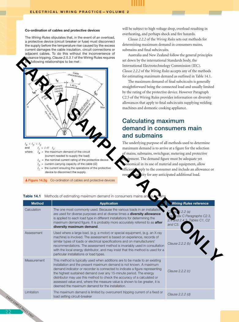
E L E C T R I C A L W I R I N G P R A C T I C E — V O L U M E 2
22
IB ≤ IN ≤ IZand I2 ≤ 1.45 IZwhere IB = the maximum demand of the circuit (current needed to supply the load) IN = the nominal current rating of the protective device IZ = current-carrying capacity of the cable (IZ) I2 = the current ensuring the operations of the protective device to disconnect the supply.
Co-ordination of cables and protective devices
The Wiring Rules stipulates that, in the event of an overload, a protective device (circuit breaker or fuse) must disconnect the supply before the temperature rise caused by the excess current damages the cable insulation, circuit connections or adjacent cables. To do this without the inconvenience of nuisance tripping, Clause 2.5.3.1 of the Wiring Rules requires the following relationships to be met :
Figure 14.3g Co-ordination of cables and protective devices
will be subject to high voltage drop, overload resulting in
overheating, and perhaps shock and fi re hazards.
Clause 2.2.2 of the Wiring Rules sets out methods for
determining maximum demand in consumers mains,
submains and fi nal subcircuits.
Australia and New Zealand follow the general principles
set down by the international Standards body, the
International Electrotechnology Commission (IEC).
Clause 2.2.2 of the Wiring Rules accepts any of the methods
for estimating maximum demand as outlined in Table 14.1.
The maximum demand of fi nal subcircuits is generally
straightforward being the connected load and usually limited
by the rating of the protective device. However Paragraph
C2.5 of the Wiring Rules provides information on diversity
allowances that apply to fi nal subcircuits supplying welding
machines and domestic cooking appliance.
Calculating maximum demand in consumers main and submains The underlying purpose of all methods used to determine
maximum demand is to arrive at a fi gure for the selection
of mains, submains, switchgear, metering and protective
equipment. The demand fi gure must be adequate yet
economical in its use of material and equipment, allow
effi cient supply to the consumer and include an allowance or
reserve capacity for any anticipated additional load.
Table 14.1 Methods of estimating maximum demand in consumers mains and submains
Method Application Wiring Rules reference
Calculation The one most commonly used. Because the various loads in an installation are used for diverse purposes and at diverse times a diversity allowance is applied to each load type in different installations for determining the maximum demand fi gure. It is probably more accurately referred to as after diversity maximum demand.
Clause 2.2.2 (a)Appendix C Paragraphs C2.3, 2.4 and 2.4.3. Tables C1, C2 and C3.
Assessment Used where a large load, (e.g. a motor) or special equipment, (e.g. an X-ray machine) is involved. The assessment is based on experience, records of similar types of loads or electrical specifi cations and on manufacturers’ recommendations. The assessment method is invariably used in consultation with the local energy distributor, and may insist that this method is used for a particular installations or load types.
Clause 2.2.2 (b)
Measurement This method is typically used when additions are to be made to an existing installation and the present maximum demand is not known. A maximum demand indicator or recorder is connected to indicate a fi gure representing the highest sustained demand over any 15-minute period. The energy distributor may use this method to check the accuracy of a calculated or assessed value and, where the measure value is shown to be greater, it is deemed the maximum demand for the installation.
Clause 2.2.2 (c)
Limitation The maximum demand is limited by overcurrent tripping current of a fi xed or load setting circuit-breaker
Clause 2.2.2 (d)
2
EARLY SAMPLE PAGES ONLY
pet86436_ch14_001-046.indd 22 9/27/11 6:59 PM
EARLY SAMPLE PAGES ONLY

23
C H A P T E R 1 4 I N S T A L L A T I O N P L A N N I N G A N D D E S I G N
As previously mentioned the calculation method for
determining maximum demand is the method most commonly
used. In this method, demand calculations are classifi ed as:
• single and multiple domestic installations (Paragraph 2.3
and Table C1)
• non-domestic installations (Paragraph C2.4 and Table C2).
Where an installation consists of both domestic and non-
domestic, known as multiple installations, the applicable
load allocation given in Tables C1 and C2 are used.
As previously mentioned maximum demand of fi nal
subcircuits is generally considered as being the connected
Load Group CalculationDemand
current (A)
Table for single phase consumers main/submains
Load Group CalculationDemand current (A)
Red White Blue
Table for three phase consumers main/submains
Make up a table as shown below1
List load types in the table as per load groups of Tables C1 or C2
2
Apply the instruction to determine the demand contribution of each load group
3
Record the demand contributions for each load group as determined in 3
4
Add the individual group demands for each phase to obtain a total
demand for each phase
5
For multiphase demands compare the phase demands for balance and if necessary rearrange
the load for better balance.
6
Note. Calculating to one decimal point is sufficiently accurate for the demand contribution of the individual load groups. However it is not unreasonable to round up the total maximum demand figure to the next whole number as cable current-carrying capacities are given as whole number values.
load and usually limited by the rating of the protective
device.
The methods used for demand calculations of all types
of installations base on the current allocated to load groups
are much the same. However, the need to set out demand
calculations in a logical and systematic manner is most
important. An effective layout of demand calculations will
reduce the possibility of error and allow for easy checking
of mathematics, load grouping and phase balancing. The
suggested approach is illustrated Figure 14.4a and the
examples that follow.
Figure 14.4a Systematic method for calculating maximum demand
3EARLY
SAMPLE PAGES ONLY
pet86436_ch14_001-046.indd 23 9/27/11 6:59 PM
EARLY SAMPLE PAGES ONLY

E L E C T R I C A L W I R I N G P R A C T I C E — V O L U M E 2
24
Note. Calculating to one decimal point is suffi ciently
accurate for the demand contribution of the individual
load groups. It is reasonable to round up the total
maximum demand fi gure to the next whole number
as cable current-carrying capacities are given as whole
number values.
Single and multiple domestic demandThe footnotes to Table C1 and the worked examples in
Appendix C of the Wiring Rules provide a guide to the
calculation of maximum demand for single and three-phase
domestic and multiple domestic installations. These should
be studied together with the following examples.
DID YOU KNOW?
Electricity distributors specifi cation for the number of phases supplied to installations that only have single-phase loads is usually based on the total maximum demand for the installation. As an example a distributor may provide an installation with single-phase where maximum demand �70 A, two-phase where maximum demand is � 70 A �140 A and three-phase where maximum demand is � 140 A.Installations that include three phase appliances, such as motors are supplied with three phases, as are installations consisting of multiple occupancies, such as a block of fl ats.
EXAMPLE 1
Determine the maximum demand for a single-phase 230 V installation that comprises:
23 lighting points
2 � 15 A plug socket-outlets
6 single and 10 double socket-outlets
10 kW range
4.8 kW controlled load water heater
4 � 300 W fl oodlights in swimming pool area.
Use Table C1, column 2, and list or tabulate the load groups to solve the problem as shown in Table 14.2. Note that, even
with lower maximum-demand current values, a minimum rating for a consumer’s mains in a domestic installation is usually
stipulated by the energy distributor.
Table 14.2 Example 1—maximum demand calculation for a simple single domestic installation
Load group Calculation Demand current
A(i) 23 lighting points 3 � 2 � 5 A 5.0
A(ii) 4 � 300 W fl oodlights4 300
2300 75 3 9
× × . = . A 3.9
B(i) 6 single � 10 double socket outlets 10 � 5 � 15 A 15.0
B(ii) 2 � 15 A socket outlets Allow 10 A 10.0
C 10 kW range10000
2300 5 21 7× . = . A 21.7
F(i) 4.8 kW controlled load water heater4800230
20 9= . A 20.9
Total demand 76.5 i.e. 77.0 A
2
EARLY SAMPLE PAGES ONLY
pet86436_ch14_001-046.indd 24 9/27/11 6:59 PM
EARLY SAMPLE PAGES ONLY

25
C H A P T E R 1 4 I N S T A L L A T I O N P L A N N I N G A N D D E S I G N
Phase demandsThe phase demands should now be examined to see whether
or not balance can be improved. In the case of example 2, a
small improvement could be made by moving the spa heater
(15.7 A) from red phase to blue phase and both the hotplate
(5.2A) and pool pump (3.6 A) form blue phase to red phase,
resulting in demands of 31.7 A, 37.3 A and 37.5 A for the red,
white, and blue phases respectively. Always check for balance
EXAMPLE 2
A single domestic installation comprises:
42 light points
4 � 300 W fl oodlights
48 socket-outlets
6.65 kW oven, 2.4 kW hotplates
Three-phase ducted air conditioning rated at 10.6 A per phase
1.2 kW pool pump rated at 3.6 A.
4.8 kW spa heater
Note that this installation will require a three-phase supply because of the ducted air conditioning.
To determine the maximum demand, arrange the load for balance over the three phases as in Table 14.3a, then employ
Table C1, column 2 (individual living unit) as shown in Table 14.3b.
Table 14.3a Example 2—arrangement of load across three phases
Red White Blue
21 light points 21 light points
4 � 300 W fl oodlights
16 Socket outlets 16 Socket outlets 16 Socket outlets
6.65 kW oven 2.4 kW hotplate
10.6 A Air conditioning 10.6 A Air conditioning 10.6 A Air conditioning
4.8 kW spa heater 3.6 A pool pump
Table 14.3b Example 2—maximum demand calculations for a single domestic installation supplied with three phase
Load group Refer Table Col. CalculationDemand current (A)
Red White Blue
A(i) Light points C1 Col 221 points per phase
3 � 2 = 5A5.0 5.0 0
A(ii) Floodlights C1 Col 2 0 0 3.9
B(i) Socket outlets C1 Col 2 16 point per phase 10.0 10.0 10.0
C Oven C1 Col 2 0 14.4 0
C Hotplates C1 Col 2 0 0 5.2
D Air conditioning C1 Col 2 10.6 � 0.75 = 7.9 A 7.9 7.9 7.9
G Spa heater C1 Col 2 4800 � 0.75 = 15.7 A 15.7 0 0
L Pool pump C2 Col 2 Full load (3.6 A) 0 0 3.6
Total demand per phase 38.6 37.3 30.6
5EARLY
SAMPLE PAGES ONLY
pet86436_ch14_001-046.indd 25 9/27/11 6:59 PM
EARLY SAMPLE PAGES ONLY

E L E C T R I C A L W I R I N G P R A C T I C E — V O L U M E 2
26
because, although only a small improvement is achieved for
this example, a signifi cant improvement can often be made
in other cases.
Maximum demand for a multiple phase installation is
taken as the heaviest loaded phase, in this example this is
blue phase at 38 A.
DID YOU KNOW?
Electricity distributors place requirements on installation supplied with multiple phases for balancing the maximum demand across phases. Typically phases must be balance be within a percentage of demand current or a maximum current value. Check this out in the local service rules for your area.
EXAMPLE 3
A block of units includes:
2 three-bedroom units
8 two-bedroom units
6 one-bedroom units.
Each unit is connected to a single-phase supply and fed by submains from the main switchboard. The individual unit loads are:
• three-bedroom unit
16 lights
18 socket-outlets in unit; 1 socket-outlet in common laundry
8 kW range
4.8 kW continuous water heater (80 W/L)
• two-bedroom unit
14 lights
14 socket-outlets in unit; 1 socket-outlet in common laundry
8 kW range
4.8 kW continuous water heater (80 W/L)
• one-bedroom unit
13 lights
12 socket-outlets in unit; 1 socket-outlet in common laundry
7 kW range
3.6 kW continuous water heater (80 W/L)
• community services
9 socket-outlets
10 lights: 6 � 75 W, 4 � 150 W outside lights.
Determine the maximum demand for the installation.
In multiple domestic installation the contribution of each load group is dependant on the number of units per phase as
given in Wiring Rules Table C1 Columns 3, 4 and 5. It is fi rst necessary to balance the units over the phases shown as in Table
14.4a. Postpone balancing community services until it is seen how the fi rst totals of phase demands work out.
2
EARLY SAMPLE PAGES ONLY
pet86436_ch14_001-046.indd 26 9/27/11 7:00 PM
EARLY SAMPLE PAGES ONLY
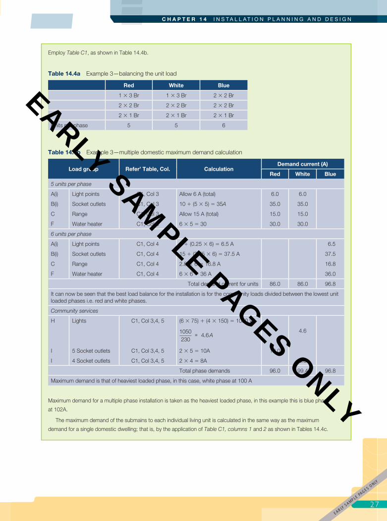
27
C H A P T E R 1 4 I N S T A L L A T I O N P L A N N I N G A N D D E S I G N
Employ Table C1, as shown in Table 14.4b.
Table 14.4a Example 3—balancing the unit load
Red White Blue
1 � 3 Br 1 � 3 Br 2 � 2 Br
2 � 2 Br 2 � 2 Br 2 � 2 Br
2 � 1 Br 2 � 1 Br 2 � 1 Br
Units per phase 5 5 6
Table 14.4b Example 3—multiple domestic maximum demand calculation
Load group Refer’ Table, Col. CalculationDemand current (A)
Red White Blue
5 units per phase
A(i) Light points C1, Col 3 Allow 6 A (total) 6.0 6.0
B(i) Socket outlets C1, Col 3 10 � (5 � 5) � 35A 35.0 35.0
C Range C1, Col 3 Allow 15 A (total) 15.0 15.0
F Water heater C1, Col 3 6 � 5 � 30 30.0 30.0
6 units per phase
A(i) Light points C1, Col 4 5 � (0.25 � 6) � 6.5 A 6.5
B(i) Socket outlets C1, Col 4 15 � (3.75 � 6) � 37.5 A 37.5
C Range C1, Col 4 2.8 � 6 � 16.8 A 16.8
F Water heater C1, Col 4 6 � 6 � 36 A 36.0
Total demand current for units 86.0 86.0 96.8
It can now be seen that the best load balance for the installation is for the community loads divided between the lowest unit loaded phases i.e. red and white phases.
Community services
H Lights C1, Col 3,4, 5 (6 � 75) � (4 � 150) � 1050 W
1050230
4 6= . A4.6
I 5 Socket outlets C1, Col 3,4, 5 2 � 5 � 10A 10.0
I 4 Socket outlets C1, Col 3,4, 5 2 � 4 � 8A 8.0
Total phase demands 96.0 99.4 96.8
Maximum demand is that of heaviest loaded phase, in this case, white phase at 100 A
Maximum demand for a multiple phase installation is taken as the heaviest loaded phase, in this example this is blue phase
at 102A.
The maximum demand of the submains to each individual living unit is calculated in the same way as the maximum
demand for a single domestic dwelling; that is, by the application of Table C1, columns 1 and 2 as shown in Tables 14.4c.
7EARLY
SAMPLE PAGES ONLY
pet86436_ch14_001-046.indd 27 9/27/11 7:00 PM
EARLY SAMPLE PAGES ONLY

E L E C T R I C A L W I R I N G P R A C T I C E — V O L U M E 2
28
Non-domestic demand It can be seen that the maximum demand assessments
considered so far follow a common pattern, and a broadly
similar approach may be used for a non-domestic
installation such as a commercial building, factory or
Table 14.4c Example 3—maximum demand calculations for submains for each unit
Three-bedroom unit
Load group Calculation Demand current
A(i) 16 lighting points Allow 3 A 3.0
B(i) 19 socket outlets Allow 10 A 10.0
C 8 kW range8000230
0 5 17 4× =. . A 21.7
F(i) 4.8 kW continuous water heater4800230
20 9= . A 20.9
Total demand55.6
i.e. 56 A
Two-bedroom unit
Load group Calculation Demand current
A(i) 14 lighting points Allow 3 A 3.0
B(i) 15 socket outlets Allow 10 A 10.0
C 8 kW range8000230
0 5 17 4× =. . A 21.7
F(i) 4.8 kW continuous water heater4800230
20 9= . A 20.9
Total demand55.6
i.e. 56 A
One-bedroom unit
Load group Calculation Demand current
A(i) 13 lighting points Allow 3 A 3.0
B(i) 13 socket outlets Allow 10 A 10.0
C 7 kW range7000230
0 5 15 2× =. . A 15.2
F(i) 3.6 kW continuous water heater3600230
15 7= . A 15.7
Total demand45.9
i.e. 44 A
residential institution. Paragraph C2.4.1 and Table C2,
together with Paragraph C2.5.2.2 (where welding
machines are installed), should be used to determine
the various diversity factors to be applied to the load
groups.
2
EARLY SAMPLE PAGES ONLY
pet86436_ch14_001-046.indd 28 9/27/11 7:00 PM
EARLY SAMPLE PAGES ONLY

29
C H A P T E R 1 4 I N S T A L L A T I O N P L A N N I N G A N D D E S I G N
EXAMPLE 4
A commercial/industrial complex consists of eight separate occupancies. The distribution board for each occupancy is
supplied from a main switchboard for the complex as shown in the diagram below. Determine the maximum demand for the
submains to a unit; allow 10% for additional future load. Note. The unit distribution board is a standard multi-pole panel board
with phases sequenced red, white and blue across ever three poles.
1 2 3 4 5 6 7 8 9 10 11 12
Neutral link
Metering CTs
Unit 1
Earth bar
Unit distribution board
Main switchboard
Unit Submain
6 sparepoles
Table 14.5a Example 4—load for each unit
Circuit Load group Rating Quantity
1 400 W High bay MV luminaires 2.1 A 6
2 400 W High bay MV luminaires 2.1 A 6
3 2 � 36 W Fluorescent troffer 0.38 A 10
4 400 W Flood lights 1.9 A 2
5 Single-phase socket outlets 10 A 10
6 Single-phase socket outlets 15A 1
7 Three-phase socket outlets 10 A 4
8 Three-phase socket outlets 20 A 1
9 Three-phase socket outlets 32 A 1
10 Water heater 2.4 kW 1
11 Oven 1.2 kW 1
12 Split air conditioner 15 A 1
Figure Example 4
9EARLY
SAMPLE PAGES ONLY
pet86436_ch14_001-046.indd 29 9/27/11 7:00 PM
EARLY SAMPLE PAGES ONLY

E L E C T R I C A L W I R I N G P R A C T I C E — V O L U M E 2
30
14.5 Selection of minimum cable size based on current-carrying capacityThe current-carrying capacity of a cable must not
be less than the current to be carried by the cable
(i.e. the maximum demand of the circuit) that it supplies.
The maximum demand, together with the previously
discussed factors affecting current-carrying capacity, is
Table 14.5b Calculation of maximum demand for the submain to each unit
Load group Refer’ Table, Col. CalculationDemand current (A)
Red White Blue
A 6- 400 W High bay MV luminaires
C2 Col 36 � 2.1 � 12.6 A 12.6
A 6- 400 W High bay MV luminaires
C2 Col 36 � 2.1 � 12.6 A 12.6
A 10 – 2 � 36 W Fluorescent troffer
C2 Col 310 � 0.38 � 3.8 A 3.8
A 2- 400 W Flood lights C2 Col 3 2 � 1.9 � 3.8A 3.8
B(ii) 10 – 10 A single-phase socket outlets
C2, Col. 2,3 1000 100 9230
8 3+ × = .( )
A 8.3
B (iii) 1 – 15 A single-phase socket outlets
C2 Col 315 A 15.0
B (iii) 4 – 10 A three-phase socket outlets
C2 Col 3 1000 100 3230
5 7+ × = .( )
A 5.7 5.7 5.7
B (iii) 1 – 20 A three-phase socket outlets
C2 Col 320 � 0.75 � 15 A 15.0 15.0 15.0
B (iii) 1 – 32 A three-phase socket outlets
C2 Col 3Full rating 32.0 32.0 32.0
C 1- 2.4 kW water heater C2 Col 3 2400230
10 4= . A 10.4
C 1-1.2 k W Oven C2 Col 3 1200230
5 2= . A 5.2
Allow 10% of heaviest loaded phase
8.4 8.4 8.4
Total phase demands 77.5 96.4 85.1
As is the case for consumers, main maximum demand for a multiple phase submain is taken as the heaviest loaded phase, in
this example this is white phase at 97 A.
Where an energy distributor has a separate tariff, it may prefer the lighting to be connected on one phase for economy in
metering, unless lighting forms a major part of the load.
the basis for determining the minimum conductor size
for a particular application. This is provided that voltage
drop and EFLI limitations and short-circuit performance
are satisfied.
Selection guideThe following examples will provide a guide to the selection
of conductor sizes and should be studied in conjunction
with the AS/NZS 3008.1. These examples refer to and
are extensions of the examples for calculating maximum
demand in Section 14.4 of this chapter.
3
EARLY SAMPLE PAGES ONLY
pet86436_ch14_001-046.indd 30 9/27/11 7:00 PM
EARLY SAMPLE PAGES ONLY

31
C H A P T E R 1 4 I N S T A L L A T I O N P L A N N I N G A N D D E S I G N
EXAMPLE 5
In the case of the single domestic dwelling of Example 1 (page 24) the maximum demand was calculated at 77 A. (Note that
the Wiring Rules place no minimum requirement for consumer’s mains; however, energy distributors commonly stipulate a
minimum cable size, for example, 16 mm2.) The consumers mains are to be single core V75 thermoplastic-sheathed (TPS)
stranded copper cables installed in heavy duty PVC conduit in air in accordance with Wiring Rules Clause 3.9.7.1.2 (i) for
consumers mains without short-circuit protection.
A starting point for referring to the correct current-carrying capacity tables in AS/NZS 3008.1 is the Table 3 series, in this
case Table 3 (2) for cables installed in a wiring enclosure.
The three tables referenced cover one of the three insulation types and
maximum conductor temperature.
As you can be see, Item 1 of the table shows that the current-carrying reference tables for two single core installed in a wiring
enclosure in air are Table 4 or 5 columns 15 to 17 or Table 6 columns 11 and 12.
Turning to theses tables in turn you can see that, Table 4 covers cables with thermoplastic, 75°C insulants and applies to
non-armoured, sheathed and unsheathed cables as indicated by Note 1 to the table.
TABLE 4Australian conditions
TABLE 4New Zealand conditions
Column 15 of the Table 4 for Australian condition shows that a 25mm2 cable with a current-carrying capacity of 94 A is the
lowest size able to carry 77 A. Under New Zealand conditions Table 4 shows that the lowest size cable is 16 mm2, having a
current-carrying capacity of 80 A.
Figure 1 Example 5
Figure 2 Example 5
EARLY SAMPLE PAGES O
NLY
pet86436_ch14_001-046.indd 31 9/27/11 7:00 PM
EARLY SAMPLE PAGES ONLY
E L E C T R I C A L W I R I N G P R A C T I C E — V O L U M E 2
32
EXAMPLE 6
The multiphase consumer’s mains supplying the single domestic dwelling of Example 2 (page 25) are to be V75 insulated single
core copper cable installed in polyvinyl chloride (PVC) conduit, underground. The maximum demand for each phase was
determined as 31.7 A, 37.3 A and 37.5 A, respectively. The minimum current-carrying capacity for all cables is to that of the
highest phase i.e. blue phase at 38 A.
For cables enclosed in underground pipes or ducts, Item 2 of Table 3(4) of AS/NZS 3008.1 refers the reader to Table
7, (which cover thermoplastic insulated cables with maximum conductor temperature of 75°C), and Columns 24 to 26 for
the suitable conductor size. The table shows that 6.00 mm2 cable with a current-carrying capacity of 45 A has suffi cient
current-carrying capacity. For New Zealand conditions the smaller size cable, 4.00 mm2 with current-carry capacity of 40 A
will comply. However, the energy distributor would likely insist on a larger cable for consumers mains, typically 16.00 mm2, to
allow for future additions and to accommodate short-circuit performance where the consumer’s mains are unprotected.
EXAMPLE 7
In the multiple domestic installation of Example 3 (pages 26–28), each fl at is to be connected to a single-phase supply and
fed by unenclosed twin TPS (75°C) copper submain installed in air from the main switchboard. The consumer’s mains are to
comprise four-core X-90 (90°C) stranded copper cable enclosed in PVC conduit in air.
The phase with the highest maximum demand in the consumer’s mains was previously calculated at 100 A. Reference to
AS/NZS 3008.1, Table 14, Column 11 indicates that for Australian conditions a 35 mm2 cable with current-carrying capacity of
114 A will meet the minimum requirements. For new Zealand a 25 mm2 cable rated at 100 A would be suffi cient. In either case
main controls and equipment would be rated at 100 A.
The maximum demand of the submain cables are 56 A for the two- and three-bedroom units and 44 A for the one-
bedroom unit. According to AS/NZS 3008.1, Table 10 the nearest-sized cable suitable is 10 mm2 rated at 60 A to supply each
two-bedroom and three-bedroom unit. The submain to each one-bedroom units would be adequately supplied by 6 mm2
cable rated at 44 A. Note that the nearest preferred value for a protection device for the 6 mm2 submains is 40 A. If a 50 A
device is used, the submain will need to be increased to 10 mm2. See ‘Relationship between cables and protective devices’
page 19 of this Chapter.
EXAMPLE 8
The submain to each unit of the commercial/industrial complex of Example 4 (pages 29–30) are to be a X-90 multicore copper
cable installed in an underground wiring enclosure at a depth of 0.5 m and all touching for part of their length.
The highest phase maximum demand was calculated at 97 A. Consulting AS/NZS 3008.1. Table 3(4), item 4, Column
4 directs the reader to current-carrying capacity Table 14, Columns 25 to 27 for cable is to be installed as a single circuit.
Column 6 reference Table 26(2) for derating factors applied to groups of circuits installed in separate enclosure.
Turning to Table 26(2), a derating factor of 0.70 is specifi ed for 8 circuits (the 8 submains of this example) installed
touching. Under these installation conditions the minimum current-carrying capacity is determined by
IC � IMD ___ k
Where: IC is the minimum current carrying capacity for the cable
IMD is the maximum demand for the circuit, and
k is the de-rating/rating factor
3
EARLY SAMPLE PAGES ONLY
pet86436_ch14_001-046.indd 32 9/27/11 7:00 PM
EARLY SAMPLE PAGES ONLY
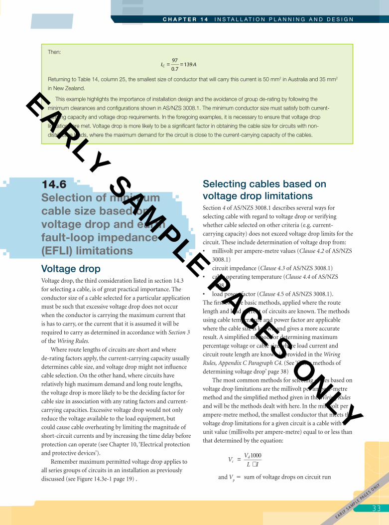
33
C H A P T E R 1 4 I N S T A L L A T I O N P L A N N I N G A N D D E S I G N
Selecting cables based on voltage drop limitationsSection 4 of AS/NZS 3008.1 describes several ways for
selecting cable with regard to voltage drop or verifying
whether cable selected on other criteria (e.g. current-
carrying capacity) does not exceed voltage drop limits for the
circuit. These include determination of voltage drop from:
• millivolt per ampere-metre values (Clause 4.2 of AS/NZS
3008.1)
• circuit impedance (Clause 4.3 of AS/NZS 3008.1)
• cable operating temperature (Clause 4.4 of AS/NZS
3008.1)
• load power factor (Clause 4.5 of AS/NZS 3008.1).
The fi rst two are basic methods, applied where the route
length and load current of circuits are known. The methods
using cable temperature and power factor are applicable
where the cable size is known and gives a more accurate
result. A simplifi ed method for determining maximum
percentage voltage or cable size where load current and
circuit route length are known is provided in the Wiring
Rules, Appendix C Paragraph C4. (See ‘Other methods of
determining voltage drop’ page 38)
The most common methods for selecting cables based on
voltage drop limitations are the millivolt per ampere-metre
method and the simplifi ed method given in the Wiring Rules
and will be the methods dealt with here. In the millivolt per
ampere-metre method, the smallest conductor that meets the
voltage drop limitations for a given circuit is a cable with a
unit value (millivolts per ampere-metre) equal to or less than
that determined by the equation:
V
V
L Ic
d=×
1000
and Vp � sum of voltage drops on circuit run
Then:
I AC = =97
0.7139
Returning to Table 14, column 25, the smallest size of conductor that will carry this current is 50 mm2 in Australia and 35 mm2
in New Zealand.
This example highlights the importance of installation design and the avoidance of group de-rating by following the
minimum clearances and confi gurations shown in AS/NZS 3008.1. The minimum conductor size must satisfy both current-
carrying capacity and voltage drop requirements. In the foregoing examples, it is necessary to ensure that voltage drop
limitations are met. Voltage drop is more likely to be a signifi cant factor in obtaining the cable size for circuits with non-
distributive loads, where the maximum demand for the circuit is close to the current-carrying capacity of the cables.
14.6 Selection of minimum cable size based on voltage drop and earth fault-loop impedance (EFLI) limitations
Voltage dropVoltage drop, the third consideration listed in section 14.3
for selecting a cable, is of great practical importance. The
conductor size of a cable selected for a particular application
must be such that excessive voltage drop does not occur
when the conductor is carrying the maximum current that
is has to carry, or the current that it is assumed it will be
required to carry as determined in accordance with Section 3
of the Wiring Rules.
Where route lengths of circuits are short and where
de-rating factors apply, the current-carrying capacity usually
determines cable size, and voltage drop might not infl uence
cable selection. On the other hand, where circuits have
relatively high maximum demand and long route lengths,
the voltage drop is more likely to be the deciding factor for
cable size in association with any rating factors and current-
carrying capacities. Excessive voltage drop would not only
reduce the voltage available to the load equipment, but
could cause cable overheating by limiting the magnitude of
short-circuit currents and by increasing the time delay before
protection can operate (see Chapter 10, ‘Electrical protection
and protective devices’).
Remember maximum permitted voltage drop applies to
all series groups of circuits in an installation as previously
discussed (see Figure 14.3e-1 page 19) .
3EARLY
SAMPLE PAGES ONLY
pet86436_ch14_001-046.indd 33 9/27/11 7:00 PM
EARLY SAMPLE PAGES ONLY
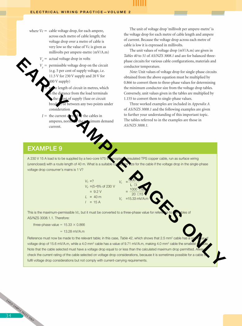
E L E C T R I C A L W I R I N G P R A C T I C E — V O L U M E 2
34
where Vc � cable voltage drop, for each ampere,
across each metre of cable length; the
voltage drop over a metre of cable is
very low so the value of Vc is given as
millivolts per ampere-metre (mV/A.m)
Vd � actual voltage drop in volts
Vp � permissible voltage drop on the circuit
(e.g. 5 per cent of supply voltage, i.e.
11.5 V for 230 V supply and 20 V for
400 V supply)
L � route length of circuit in metres, which
is the distance from the load terminals
to the point of supply (fuse or circuit
breaker) or between any two points under
consideration
I � the current carried by the cables in
amperes, normally the maximum demand
current.
The unit of voltage drop ‘millivolt per ampere-metre’ is
the voltage drop for each metre of cable length and ampere
of current. Because the voltage drop across each metre of
cable is low it is expressed in millivolts.
The unit values of voltage drop (mV/A.m) are given in
Tables 40 to 51 of AS/NZS 3008.1 and are for balanced three-
phase circuits for various cable confi gurations, materials and
conductor temperature.
Note: Unit values of voltage drop for single-phase circuits
obtained from the above equation must be multiplied by
0.866 to convert them to three-phase values for determining
the minimum conductor size from the voltage drop tables.
Conversely, unit values given in the tables are multiplied by
1.155 to convert them to single-phase values.
Three worked examples are included in Appendix A
of AS/NZS 3008.1 and the following examples are given
to further your understanding of this important topic.
The tables referred to in the examples are those in
AS/NZS 3008.1.
EXAMPLE 9
A 230 V 15 A load is to be supplied by a two-core V75 thermoplastic-insulated TPS copper cable, run as surface wiring
(unenclosed) with a route length of 40 m. What is a suitable conductor size for the cable if the voltage drop in the single-phase
voltage drop consumer’s mains is 1 V?
V
V
L
I
VC
d
c== −===
=?
( )%
.
5 1 230
9 2
40
15
1000
of V
V
m
A
Vd
LL l
mV A m
×
= ××
=
1000 9220 15
15 33Vc . / .
This is the maximum-permissible Vc, but it must be converted to a three-phase value for reference to the tables of
AS/NZS 3008.1.1. Therefore:
three-phase value � 15.33 � 0.866
� 13.28 mV/A.m
Reference must now be made to the relevant table; in this case, Table 42, which shows that 2.5 mm2 cable has a unit value of
voltage drop of 15.6 mV/A.m, while a 4.0 mm2 cable has a value of 9.71 mV/A.m, making 4.0 mm2 cable the smallest suitable.
Note that the cable selected must have a voltage drop equal to or less than the calculated maximum drop permitted. Always
check the current rating of the cable selected on voltage drop considerations, because it is sometimes possible for a cable to
fulfi l voltage drop considerations but not comply with current-carrying requirements.
3
EARLY SAMPLE PAGES ONLY
pet86436_ch14_001-046.indd 34 9/27/11 7:00 PM
EARLY SAMPLE PAGES ONLY

35
C H A P T E R 1 4 I N S T A L L A T I O N P L A N N I N G A N D D E S I G N
EXAMPLE 11
A three-phase 400 V motor having a rated full-load current of 50 A is to be supplied by a three-core 1/1 kV MIMS cable with
a route length of 60 m from the main switchboard to the motor position in a boiler room. Determine the minimum size of cable
required for the circuit if the voltage drop in the consumer’s mains is 8 V:
V
V
L
I
V =V
L Ic
d
cd=
= −===
×
= ×
?
20 8
12
60
50
1000
1000 V
m
A
11260 50
4 00×
= m A mV/. .
Reference to Table 48 for MIMS cable, conductor temperature 100ºC, shows that a 10 mm2 cable is suitable, with a Vc value of
3.92 mV/A.m. Checking the current-carrying capacity of the cable, Table 19, column 5 shows that the cable is able to carry 73 A.
The equation: V =V
L Ic
d1000×
may of course be transposed to provide:
1. The maximum route length permitted for a particular cable and current:
LV
V Id
c
=×
1000
2. The maximum current permitted on a cable if route length and cable type are known:
I =V
L Vd
c
1000×
EXAMPLE 10
A single-phase fi nal subcircuit is limited to a voltage drop of 6 V due the voltage drop in the consumer’s mains and submains.
The circuit is wired in twin V75 thermoplastic-insulated TPS copper cable, unenclosed, to supply a 30 A 230 V factory load at
a distance of 8 m from the protective circuit breaker at the distribution board. What size cable should be selected?
V
V
L
I
VV
L Ic
d
cd
====
=×
= ××
=
?
6
8
30
1000
1000 68 30
2
V
M
A 5 mV/A.m
Converting to a three-phase value:
Vc � 25 � 0.866
� 21.65 mV/A.m
Using Table 42, conductor temperature 75ºC, it can be seen that a 1.5 mm2 cable fulfi ls the voltage drop considerations, but
its current-carrying capacity is only 21 A (Table 10, Column 5), and to comply with Clause 3.4 of AS/NZS 3000, a 2.5 mm2
cable rated at 30 A is necessary.
5EARLY
SAMPLE PAGES ONLY
pet86436_ch14_001-046.indd 35 9/27/11 7:00 PM
EARLY SAMPLE PAGES ONLY

E L E C T R I C A L W I R I N G P R A C T I C E — V O L U M E 2
36
EXAMPLE 12
What is the maximum-permissible route length for a three-phase 400 V three-wire circuit, protected by a 30 A ‘C’-type circuit
breaker, using 6 mm2 thermoplastic-insulated unsheathed V90 copper cables in PVC conduit? Because of voltage drop in the
consumer’s mains, the voltage drop in the circuit is limited to 3.5 per cent.
To determine the maximum-permissible route length, so as not to exceed the maximum voltage drop permitted, fi rst transpose
the voltage drop equation. Then:
L
V
V
Id
=== ×==
?
.c
V
400 0 35
14
300
1000
1000 14681 30
68 5A
m
L =V
V I
=
L =
d
c ××
×.
6.81 mV/A.m (Table 40)
EXAMPLE 14
An existing 95 m run of three-core 4 mm2 V75 thermoplastic-insulated sheathed cables supplies a three-phase 400 V 19 A
motor in a factory; protection is by a 20 A ‘D’-type circuit breaker. It is proposed that a small 400 V 2 A motor be added,
bringing the cable loading up to 24 A. Is this permissible if the voltage drop in the circuit must not exceed 18 V?
First check voltage drop limitation for the required current-carrying capacity:
I
V
V
L
I =V
c
d
====
?
9.71 mV/A.m (Table 42)18
95
1000
V
m
dd
cL V
=
=
××
×1000 1845 9 71
19 51.
. A
EXAMPLE 13
A 4 mm2 V75 two-core TPS copper cable, unenclosed, is supplying a 10 A load on a 230 V circuit, which has a route length of
50 m. What additional current could this cable carry without exceeding the permissible voltage drop for the circuit (Vd ) of 9.2 V?
Table 42 shows that for a 4.00 mm2 cable the three-phase Vc � 9.71, and multiplying by 1.155 � 11.22 mV/A.m for the
single-phase circuit in question. To determine the maximum current that may be carried by the cable while not exceeding
permissible voltage drop, fi rst transpose the equation for the current. Then:
I =V
L V
=
=
d
c
1000
1000 4250 112216 4
××
×. A
Accordingly, the load may be increased to 16.4 A, an increase of 6.4 A. Notice, however, that the 16.4 A is the maximum
current permissible, because of the long cable run, but is well below the cable’s current-carrying capacity of 39 A shown in,
Table 10, Columns 5.
3
EARLY SAMPLE PAGES ONLY
pet86436_ch14_001-046.indd 36 9/27/11 7:00 PM
EARLY SAMPLE PAGES ONLY
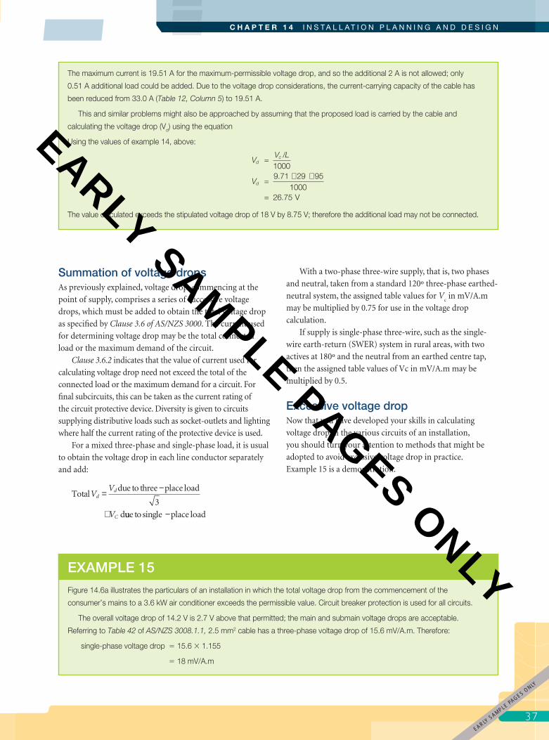
37
C H A P T E R 1 4 I N S T A L L A T I O N P L A N N I N G A N D D E S I G N
Summation of voltage dropsAs previously explained, voltage drop, commencing at the
point of supply, comprises a series of successive voltage
drops, which must be added to obtain the total voltage drop
as specifi ed by Clause 3.6 of AS/NZS 3000. The current used
for determining voltage drop may be the total connected
load or the maximum demand of the circuit.
Clause 3.6.2 indicates that the value of current used for
calculating voltage drop need not exceed the total of the
connected load or the maximum demand for a circuit. For
fi nal subcircuits, this can be taken as the current rating of
the circuit protective device. Diversity is given to circuits
supplying distributive loads such as socket-outlets and lighting
where half the current rating of the protective device is used.
For a mixed three-phase and single-phase load, it is usual
to obtain the voltage drop in each line conductor separately
and add:
Totaldue to three place load
3
d
VV
V
dd
C
= −
+ uue tosingle place load−
With a two-phase three-wire supply, that is, two phases
and neutral, taken from a standard 120º three-phase earthed-
neutral system, the assigned table values for Vc in mV/A.m
may be multiplied by 0.75 for use in the voltage drop
calculation.
If supply is single-phase three-wire, such as the single-
wire earth-return (SWER) system in rural areas, with two
actives at 180º and the neutral from an earthed centre tap,
then the assigned table values of Vc in mV/A.m may be
multiplied by 0.5.
Excessive voltage dropNow that you have developed your skills in calculating
voltage drop in the various circuits of an installation,
you should turn your attention to methods that might be
adopted to avoid excessive voltage drop in practice.
Example 15 is a demonstration.
EXAMPLE 15
Figure 14.6a illustrates the particulars of an installation in which the total voltage drop from the commencement of the
consumer’s mains to a 3.6 kW air conditioner exceeds the permissible value. Circuit breaker protection is used for all circuits.
The overall voltage drop of 14.2 V is 2.7 V above that permitted; the main and submain voltage drops are acceptable.
Referring to Table 42 of AS/NZS 3008.1.1, 2.5 mm2 cable has a three-phase voltage drop of 15.6 mV/A.m. Therefore:
single-phase voltage drop � 15.6 � 1.155
� 18 mV/A.m
The maximum current is 19.51 A for the maximum-permissible voltage drop, and so the additional 2 A is not allowed; only
0.51 A additional load could be added. Due to the voltage drop considerations, the current-carrying capacity of the cable has
been reduced from 33.0 A (Table 12, Column 5) to 19.51 A.
This and similar problems might also be approached by assuming that the proposed load is carried by the cable and
calculating the voltage drop (Vd) using the equation
Using the values of example 14, above:
V =V L
V =
=
dc
d
/10009 71 29 95
100026 75
.
.
× ×
V
The value calculated exceeds the stipulated voltage drop of 18 V by 8.75 V; therefore the additional load may not be connected.
7EARLY
SAMPLE PAGES ONLY
pet86436_ch14_001-046.indd 37 9/27/11 7:00 PM
EARLY SAMPLE PAGES ONLY
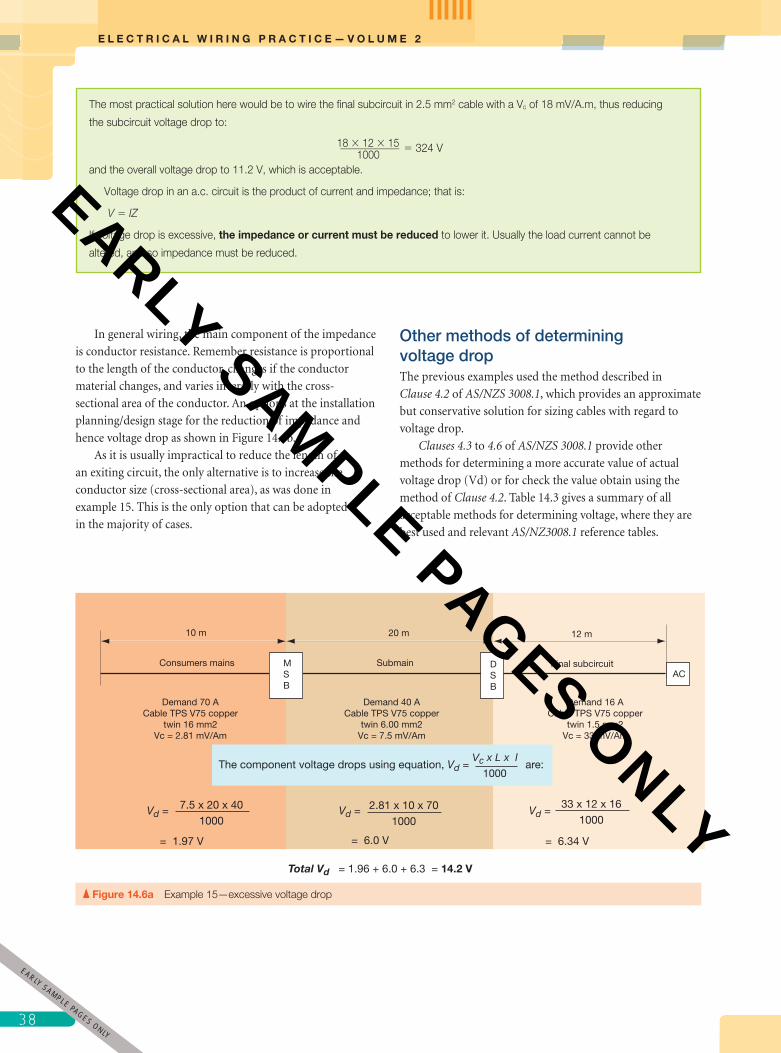
E L E C T R I C A L W I R I N G P R A C T I C E — V O L U M E 2
38
In general wiring, the main component of the impedance
is conductor resistance. Remember resistance is proportional
to the length of the conductor, changes if the conductor
material changes, and varies inversely with the cross-
sectional area of the conductor. An options at the installation
planning/design stage for the reduction of impedance and
hence voltage drop as shown in Figure 14.6b.
As it is usually impractical to reduce the length of
an exiting circuit, the only alternative is to increase the
conductor size (cross-sectional area), as was done in
example 15. This is the only option that can be adopted
in the majority of cases.
Other methods of determining voltage dropThe previous examples used the method described in
Clause 4.2 of AS/NZS 3008.1, which provides an approximate
but conservative solution for sizing cables with regard to
voltage drop.
Clauses 4.3 to 4.6 of AS/NZS 3008.1 provide other
methods for determining a more accurate value of actual
voltage drop (Vd) or for check the value obtain using the
method of Clause 4.2. Table 14.3 gives a summary of all
acceptable methods for determining voltage, where they are
best used and relevant AS/NZ3008.1 reference tables.
The most practical solution here would be to wire the fi nal subcircuit in 2.5 mm2 cable with a Vc of 18 mV/A.m, thus reducing
the subcircuit voltage drop to:
18 � 12 � 15 ___________ 1000
� 324 V
and the overall voltage drop to 11.2 V, which is acceptable.
Voltage drop in an a.c. circuit is the product of current and impedance; that is:
V � IZ
If voltage drop is excessive, the impedance or current must be reduced to lower it. Usually the load current cannot be
altered, and so impedance must be reduced.
ACDSB
MSB
Demand 70 ACable TPS V75 copper
twin 16 mm2Vc = 2.81 mV/Am
Demand 40 ACable TPS V75 copper
twin 6.00 mm2Vc = 7.5 mV/Am
Demand 16 ACable TPS V75 copper
twin 1.5 mm2Vc = 33 mV/Am
= 1.97 V = 6.0 V = 6.34 V
The component voltage drops using equation, Vd = are:Vc x L x l
1000
Consumers mains Final subcircuitSubmain
10 m 20 m 12 m
2.81 x 10 x 70
1000Vd =
33 x 12 x 16
1000Vd =7.5 x 20 x 40
1000Vd =
Total Vd = 1.96 + 6.0 + 6.3 = 14.2 V
Figure 14.6a Example 15—excessive voltage drop
3
EARLY SAMPLE PAGES ONLY
pet86436_ch14_001-046.indd 38 9/27/11 7:00 PM
EARLY SAMPLE PAGES ONLY

39
C H A P T E R 1 4 I N S T A L L A T I O N P L A N N I N G A N D D E S I G N
Figure 14.6b Avoiding excessive voltage drop
Avoiding exessive voltage dropIn the planning/design stage long runs of conductors having small cross-sectional areas, with their resultant high voltage drops can be avoided by using distribution boards situated as close as practical to the centre of the electrical load. With the approval of the energy distributor, it is sometimes possible to reduce the length of the consumer’s mains by a suitable point of attachment and main switchboard position.
3M
1M
Main switchboard
Consumers mains
Long runs of final subcircuits
3M
1M
Main switchboard
Distribution board
Consumers mains
Submain
The route length of final subcircuits is reduced by the use of a distributuion
board closer to these loads
Arrangement without a distribution board
Arrangement with a distribution board
NOTE.The comparative costs of alternative arrangements are a major factor in the final installation design.
A simplifi ed method for determining voltage drop is
provided in the Wiring Rules, Appendix C Paragraph C4. It
allows the cable size circuit, length and/or % voltage drop to
be determined using ampere-metres per percent of voltage
drop (A.m per %Vd) values rather than V
c values directly. It
also provides for percentage voltage drops in single- and three-
phase circuits in series group to be added directly. The Wiring
Rules, Table C4 provides values A.m per %Vd for single and
three phase circuits for V75 cables, sizes 1.mm2 to 95 mm2.
Examples of the application of this method are given in
Paragraph C4 of the Wiring Rules.
Ampere-metres per percent of voltage drop value
for other cable temperatures can be tabulated from the
expression: 10 V
VO
C
×
Where Vo � Supply voltage
Vc � Unit value of voltage drop (mV/A.m) for a
given conductor size and temperature for
a given circuit power factor given in the
voltage drop table of AS/NZS 3008.1
Earth fault-loop impedanceThe effect of voltage drop limitations on a circuit is to limit
its route length for a given cable size and maximum demand.
For example, a 3 per cent voltage drop applied to a fi nal
subcircuit with 2.5 mm2 active conductors and protected by
a 20 A circuit breaker is limited to a maximum route length
of 19 m:
3% Vd � 230 � 0.03
� 6.9 V.
Note: The three-phase Vc value for multicore 2.5 mm2 cable
at 75ºC is 15.6 mV/A.m (Table 42 AS/NZS 308.1). Then:
single-phase Vc � 15.6 � 1.155
� 18.02 mV/A.m.
Then:
LV
V dd
c
=×
= ×.
= .
1000
1000 69
18 02 2019 15 m
×
9EARLY
SAMPLE PAGES ONLY
pet86436_ch14_001-046.indd 39 9/27/11 7:00 PM
EARLY SAMPLE PAGES ONLY
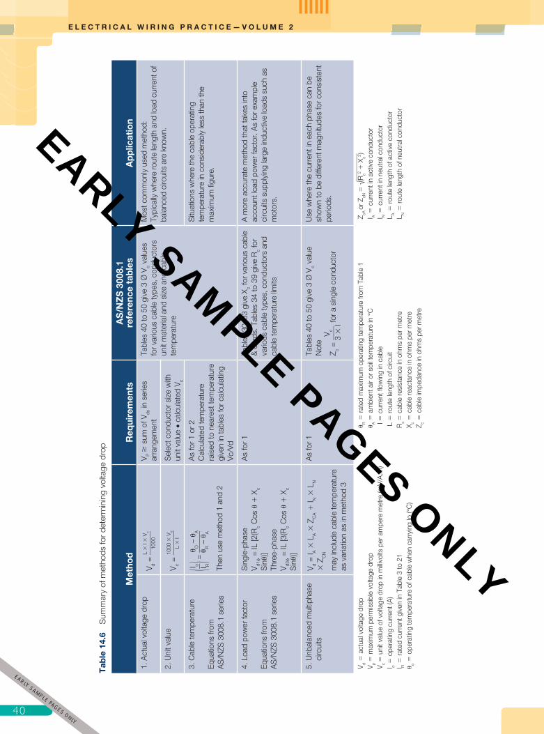
E L E C T R I C A L W I R I N G P R A C T I C E — V O L U M E 2
40
Tab
le 1
4.6
Sum
mar
y of
met
hods
for
dete
rmin
ing
volta
ge d
rop
Met
hod
Req
uire
men
tsA
S/N
ZS
300
8.1
refe
renc
e ta
bles
App
licat
ion
1. A
ctua
l vol
tage
dro
pV d
= L
� I
� V
c
____
___
1000
V P �
sum
of V
ds in
ser
ies
arra
ngem
ent
Tabl
es 4
0 to
50
give
3 Ø
Vc v
alue
s fo
r var
ious
cab
le ty
pes,
con
duct
ors
unit
mat
eria
l and
siz
e an
d ca
ble
tem
pera
ture
Mos
t com
mon
ly u
sed
met
hod:
Typi
cally
whe
re ro
ute
leng
th a
nd lo
ad c
urre
nt o
f ba
lanc
ed c
ircui
ts a
re k
now
n.2.
Uni
t val
ueV c =
1000
� V
d
____
___
L �
I
Sel
ect c
ondu
ctor
siz
e w
ith
unit
valu
e •
calc
ulat
ed V
c
3. C
able
tem
pera
ture
Equa
tions
from
A
S/N
ZS 3
008.
1 se
ries
( I o __
I R
) = O
–
A
____
__
R –
A
Then
use
met
hod
1 an
d 2
As
for 1
or 2
Cal
cula
ted
tem
pera
ture
ra
ised
to n
eare
st te
mpe
ratu
re
give
n in
tabl
es fo
r cal
cula
ting
Vc/V
d
Situ
atio
ns w
here
the
cabl
e op
erat
ing
tem
pera
ture
in c
onsi
dera
bly
less
than
the
max
imum
fi gu
re.
4. L
oad
pow
er fa
ctor
Equa
tions
from
A
S/N
ZS 3
008.
1 se
ries
Sin
gle-
phas
eV d1
=
IL [2
(Rc C
os
� X
c S
in)
]Th
ree-
phas
eV d3
=
IL [3
(Rc C
os
� X
c S
in)
]
As
for 1
Ta
bles
30–
33 g
ive
X c for
var
ious
cab
le
& c
ords
. Tab
les
34 to
39
give
Rc f
or
vario
us c
able
type
s, c
ondu
ctor
s an
d ca
ble
tem
pera
ture
lim
its
A m
ore
accu
rate
met
hod
that
take
s in
to
acco
unt l
oad
pow
er fa
ctor
. As
for e
xam
ple
circ
uits
sup
plyi
ng la
rge
indu
ctiv
e lo
ads
such
as
mot
ors.
5. U
nbal
ance
d m
ultip
hase
ci
rcui
tsV d
= I A
� L
A �
ZC
A �
I N �
LN
� Z
CN
may
incl
ude
cabl
e te
mpe
ratu
re
as v
aria
tion
as in
met
hod
3
As
for 1
Tabl
es 4
0 to
50
give
3 Ø
Vc v
alue
Not
e
Z c =
V c __
__
3 �
I for a
sin
gle
cond
ucto
r
Use
whe
re th
e cu
rren
t in
each
pha
se c
an b
e sh
own
to b
e di
ffere
nt m
agni
tude
s fo
r con
sist
ent
perio
ds.
V d �
act
ual v
olta
ge d
rop
V p �
max
imum
per
mis
sibl
e vo
ltage
dro
pV c
� u
nit v
alue
of v
olta
ge d
rop
in m
illivo
lts p
er a
mpe
re m
etre
(mV/
A.m
)I o �
ope
ratin
g cu
rren
t (A
)I R
� ra
ted
curr
ent g
iven
in T
able
3 to
21
o � o
pera
ting
tem
pera
ture
of c
able
whe
n ca
rryi
ng Io
(°C
)
R �
rate
d m
axim
um o
pera
ting
tem
pera
ture
from
Tab
le 1
A �
am
bien
t air
or s
oil t
empe
ratu
re in
°C
I �
cur
rent
fl ow
ing
in c
able
L �
rout
e le
ngth
of c
ircui
tR
c � c
able
resi
stan
ce in
ohm
s pe
r met
reX c �
cab
le re
acta
nce
in o
hms
per m
etre
Z c � c
able
impe
danc
e in
ohm
s pe
r met
re
Z cA o
r ZcN
� √__
____
___
(Rc2
� X
c2 )
I A �
cur
rent
in a
ctiv
e co
nduc
tor
I N �
cur
rent
in n
eutr
al c
ondu
ctor
L A �
rout
e le
ngth
of a
ctiv
e co
nduc
tor
L N �
rout
e le
ngth
of n
eutr
al c
ondu
ctor
4
EARLY SAMPLE PAGES ONLY
pet86436_ch14_001-046.indd 40 9/27/11 7:00 PM
EARLY SAMPLE PAGES ONLY
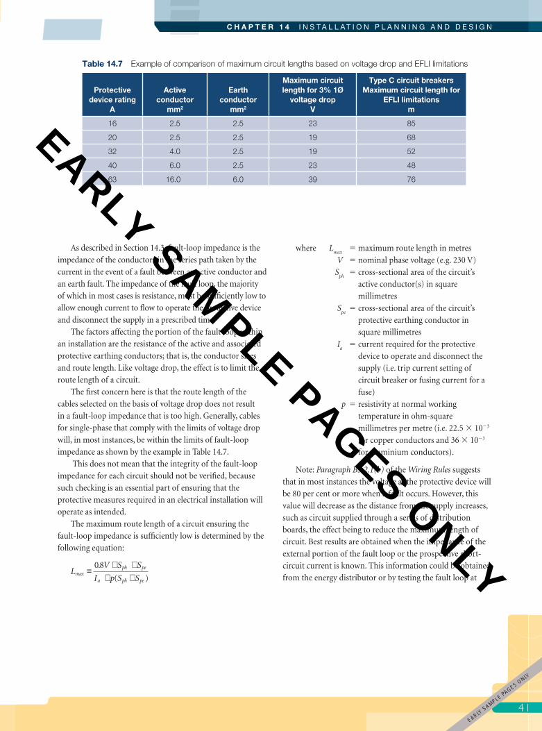
41
C H A P T E R 1 4 I N S T A L L A T I O N P L A N N I N G A N D D E S I G N
As described in Section 14.3, fault-loop impedance is the
impedance of the conductors in the series path taken by the
current in the event of a fault between an active conductor and
an earth fault. The impedance of the fault loop, the majority
of which in most cases is resistance, must be suffi ciently low to
allow enough current to fl ow to operate the protective device
and disconnect the supply in a prescribed time.
The factors affecting the portion of the fault loop within
an installation are the resistance of the active and associated
protective earthing conductors; that is, the conductor sizes
and route length. Like voltage drop, the effect is to limit the
route length of a circuit.
The fi rst concern here is that the route length of the
cables selected on the basis of voltage drop does not result
in a fault-loop impedance that is too high. Generally, cables
for single-phase that comply with the limits of voltage drop
will, in most instances, be within the limits of fault-loop
impedance as shown by the example in Table 14.7.
This does not mean that the integrity of the fault-loop
impedance for each circuit should not be verifi ed, because
such checking is an essential part of ensuring that the
protective measures required in an electrical installation will
operate as intended.
The maximum route length of a circuit ensuring the
fault-loop impedance is suffi ciently low is determined by the
following equation:
LV S S
I p S Smax
ph pe
a ph pe
=× ×
× +08.
( )
where Lmax
� maximum route length in metres
V � nominal phase voltage (e.g. 230 V)
Sph
� cross-sectional area of the circuit’s
active conductor(s) in square
millimetres
Spe
� cross-sectional area of the circuit’s
protective earthing conductor in
square millimetres
Ia � current required for the protective
device to operate and disconnect the
supply (i.e. trip current setting of
circuit breaker or fusing current for a
fuse)
p � resistivity at normal working
temperature in ohm-square
millimetres per metre (i.e. 22.5 � 10�3
for copper conductors and 36 � 10�3
for aluminium conductors).
Note: Paragraph B5.2.1(b) of the Wiring Rules suggests
that in most instances the voltage at the protective device will
be 80 per cent or more when a fault occurs. However, this
value will decrease as the distance from the supply increases,
such as circuit supplied through a series of distribution
boards, the effect being to reduce the maximum length of
circuit. Best results are obtained when the impedance of the
external portion of the fault loop or the prospective short-
circuit current is known. This information could be obtained
from the energy distributor or by testing the fault loop at
Table 14.7 Example of comparison of maximum circuit lengths based on voltage drop and EFLI limitations
Protective device rating
A
Active conductor
mm2
Earth conductor
mm2
Maximum circuit length for 3% 1Ø
voltage dropV
Type C circuit breakers Maximum circuit length for
EFLI limitationsm
16 2.5 2.5 23 85
20 2.5 2.5 19 68
32 4.0 2.5 19 52
40 6.0 2.5 23 48
63 16.0 6.0 39 76
EARLY SAMPLE PAGES O
NLY
pet86436_ch14_001-046.indd 41 9/27/11 7:00 PM
EARLY SAMPLE PAGES ONLY

E L E C T R I C A L W I R I N G P R A C T I C E — V O L U M E 2
42
the point where the protective devices are to be installed
although.
Given the previous discussion on voltage drop, it is clear
that the maximum route length of a circuit must satisfy the
limitation of both the fault-loop impedance and voltage
drop. That is:
LS S
I p S S
V
V I
maxph pe
a ph pe
d
c
=× ×
× ×
=×
08
1000
.
( )
V
EXAMPLE 16
The maximum route length determined in example 12 was 68.5 m for the three-phase circuit. Does this satisfy the fault-loop
impedance limit?
Lmax � ?
V � 230 V
Sph � 6 mm2
Spe � 2.5 mm2 (from Table 5.1 of the Wiring Rules)
Ia � 225 A (mean tripping current for a Type C circuit breaker is 7.5 times rated current)
r � 22.5 ´ 10�3
L =
V S Sl p S S
maxph pe
a ph pe
0 8.( )× ×
× ×
=
0 8 230 60 2 5225 0 0225 60 25
. .. ( )
× × ×× × +
� 64.12 m
The route length determined for voltage drop at 68.5 m is clearly too long to meet the limits of fault-loop impedance. The
solution would be to increase the size of the protective earthing conductor to 4.0 mm2, which would increase the maximum
fault-loop impedance length to 87.23 m and thus satisfy both limitations, as shown below:
L =max
0 8 230 60 4 0225 0 0225 60 4 0
. .. ( . )
× × ×× × +
� 87.23 m
EXAMPLE 17
Would impedance of the existing circuit in example 14 be low enough to trip the circuit breaker if a fault to earth occurs?
Lmax � ?
V � 230 V
Sph � 4 mm2
Spe � 2.5 mm2 (from Table 5.1 of the Wiring Rules)
Ia � 250 A (mean tripping current for this Type D circuit breaker is 12.5 times the rated current)
p � 22.5 � 10�3
L =V S S
l p S Smax
ph pe
a ph pe
0 8.( )
× ×× × ×
=
0 8 230 4 0 2 5225 0 0225 4 0 25
. . .. ( . )
× × ×× × +
� 50.32 m
4
EARLY SAMPLE PAGES ONLY
pet86436_ch14_001-046.indd 42 9/27/11 7:00 PM
EARLY SAMPLE PAGES ONLY

43
C H A P T E R 1 4 I N S T A L L A T I O N P L A N N I N G A N D D E S I G N
14.7 Short-circuit temperature performance of cablesSection 5 of AS/NZS 3008.1 provides guidance on the
selection of cables likely to be subject to damage from a
short-circuit. Under a short-circuit of negligible impedance
i.e. a ‘bolted fault’, a cable will heat rapidly due to the
high current that will fl ow. Cable temperature might rise
to a point where the insulation, sheath or conductor is
permanently damaged. This problem is usually limited to
cables subject to high prospective fault currents, such as a
consumer’s mains connected directly from a distribution
transformer to the main switchboard of a large installation.
In this text, selecting cables on short-circuit temperatures
limitations are given as a basic understanding of the concept
and factors involved (fi gure 14.7) so that you may recognise
such situation and seek advice from cable manufacturers or
other experts in the fi eld.
Clearly the route length of the circuit is excessive to meet the fault-loop impedance limits. The impedance to ensure operation
of the protective device can be calculated from Ohm’s Law Z � 0.8 V/Ia � 0.8 (230/250 � 0.73 Ω. The fault-loop impedance
of the circuit at 95 m is approximately 1.39 Ω, as determined from the a.c. resistance values for 4.0 mm2 and 2.5 mm2
conductors given in Table 35 of AS/NZS 3008.1.
Being an existing circuit and short of rewiring, the likely solution would be to install an RCD. Because RCDs have such a
low trip current (in this case a 100 mA device would suffi ce), the impedance of the fault path is not as critical (Z � 0.8 V/I � 0.8
� 230/0.1 � 1840 Ω) as it is for a circuit breaker (0.73 Ω) in providing protection against indirect contact, in accordance with
Clauses 1.5.6 and 2.6 of the Wiring Rules.
Short-circuitHigh fault current
Duration of fault
Heated conductor expands rapidly placing mechanical stress on insulation, sheath and bedding components.
Cable should be installed to allow movement of expansion with no sections under mechanical stress, for example where cables bend or pass over structural components.
Protectivecircuit breaker
°C
Conductor temperature Clause 5.3 of AS/NZS 3008.1 provides an equation from which minimum conductors size or the maximum level of fault for given cable size could be determined as follows:
S = √ K2
I2t where I = short-circuit current (r.m.s. over duration), in amperes t = duration of short circuit, in seconds K = constant depending on the material of the current-carrying component, the initial temperature and the final temperature (Table 52 gives values of constant (K)) S = cross-sectional area of the current-carrying component, in square millimetres.Alternatively the maximum level of fault for given cable size could be determined by:
I = √K2 S2
t
Final temperature —Temperature limits for insulation materials in contact with conductors as given in AS/NZS3008.1 Table 53
Initial temperature —Maximum operating temperature of conductor for insulation type as given in AS/NZS3008.1 Table 1
Figure 14.7 Concept of short-circuit temperature limitations of cables
3EARLY
SAMPLE PAGES ONLY
pet86436_ch14_001-046.indd 43 9/27/11 7:00 PM
EARLY SAMPLE PAGES ONLY
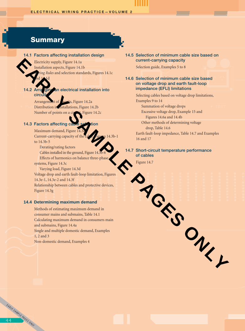
E L E C T R I C A L W I R I N G P R A C T I C E — V O L U M E 2
44
14.1 Factors affecting installation design
Electricity supply, Figure 14.1a
Installation aspects, Figure 14.1b
Wiring Rules and selection standards, Figures 14.1c
and 14.1d
14.2 Arranging an electrical installation into circuits
Arrangement of circuits, Figure 14.2a
Distribution in installations, Figure 14.2b
Number of points on a circuit, Figure 14.2c
14.3 Factors affecting cable selection
Maximum demand, Figure 14.3a
Current-carrying capacity of the cable, Figures 14.3b-1
to 14.3b-5
Derating/rating factors
Cables installed in the ground, Figure 14.3b-6
Effects of harmonics on balance three-phase
systems, Figure 14.3c
Varying load, Figure 14.3d
Voltage drop and earth fault-loop limitation, Figures
14.3e-1, 14.3e-2 and 14.3f
Relationship between cables and protective devices,
Figure 14.3g
14.4 Determining maximum demand
Methods of estimating maximum demand in
consumer mains and submains, Table 14.1
Calculating maximum demand in consumers main
and submains, Figure 14.4a
Single and multiple domestic demand, Examples
1, 2 and 3
Non-domestic demand, Examples 4
14.5 Selection of minimum cable size based on current-carrying capacity
Selection guide, Examples 5 to 8
14.6 Selection of minimum cable size based on voltage drop and earth fault-loop impedance (EFLI) limitations
Selecting cables based on voltage drop limitations,
Examples 9 to 14
Summation of voltage drops
Excessive voltage drop, Example 15 and
Figures 14.6a and 14.4b
Other methods of determining voltage
drop, Table 14.6
Earth fault-loop impedance, Table 14.7 and Examples
16 and 17
14.7 Short-circuit temperature performance of cables
Figure 14.7
Summary
4
EARLY SAMPLE PAGES ONLY
pet86436_ch14_001-046.indd 44 9/27/11 7:00 PM
EARLY SAMPLE PAGES ONLY
45
C H A P T E R 1 4 I N S T A L L A T I O N P L A N N I N G A N D D E S I G N
1. What must be known about an electrical installation
before an work can commence?
2. Explain how the available electricity supply may effect
the installation design.
3. Describe aspect of an installation that may affect its
design.
4. What Wiring Rules requirement for the wiring system
must be met in the design of an electrical installation?
5. List the Wiring Rules Clauses that must be considered
when planning and selecting equipment for an electrical
installation.
6. Outline cable selection procedures given in AS/NZS
3008.1 Section 2.
7. Where could you use the information in Appendix C
Tables C5 and C6 of the Wiring Rules?
8. List the factors that that should to be considered when
arranging an electrical installation into circuits.
9. When arranging an installation why is it necessary to
consider the intended use of socket outlets?
10. What effect could the installation of electric motors
have of how and an installation is arranged?
11. What effect does frequent overloading have on circuit
wiring?
12. Why is it important to limit the number of socket
outlets on a circuit for the connection of Class 1
appliance?
13. What is the maximum recommended number of light
points on a 1.5 mm2 circuit protected by a 16 A circuit
breaker.
14. Describe two typical situation where the arrangement of
the installation includes additional distribution boards.
15. Name an advantage in arranging an installation with a
distribution board remote from the main switchboard.
16. In the diagram below show the basic arrangement of
consumers mains, submain and fi nal subcircuits.
17. Describe what is meant by the term ‘maximum demand’.
18. What features limit its current-carrying capacity of a
cable?
19. Name the type of cable that may have a maximum
operating temperature of 250°C and the conditions
under which this is permitted.
20. State the ambient temperature base for current-carrying
capacity of cables in Australia and in New Zealand.
21. What is the effect on current-carrying capacity of a
cable if it can be shown that the ambient temperature in
which the cable is to be installed is lower than the base
ambient temperature?
22. What is the current carrying capacity for a 6 mm2
two core thermoplastic sheathed cable with stranded
conductors installed spaced in air?
23. How would the current-carrying capacity of the cable in
question 22 be affected if for 3.00 m of its route length it
is installed partially surrounded by thermal insulation?
24. How can direct sun light effect a cable?
25. With aid of a diagram show how a group of three
multicore cable would be install horizontally on ‘ladder
support’ to avoid the need to derate their current-
carrying capacity.
26. Determine the current-carrying capacity of a cable for
a circuit with a maximum demand of 20 A where the
cable is installed unenclosed on a cable tray bunched
with two other circuits.
27. What installation conditions and external factor affect
the current-carrying capacity of cables in underground
wiring system.
28. Explain the term ‘thermal resistivity of soil’.
29. Briefl y explain the affects of 3rd harmonic in three-
phase 4 four systems.
30. What information do Tables 3(1) to 3(4) of AS/NZS
3008.1 provide.
31. Identify the group of AS/NZS 3008.1 table that give
current-carrying capacity for cables with cross-linked
elastomeric (90 °C) insulation.
32. Which AS/NZS 3008.1 table specifi es de-rating factors
for multicore cables for groups of circuits installed on
cable tray.
33. What advantage can be taken in selecting cables for
loads that have intermittent or cyclic operation.
Review questions
Main switchboard
Distribution board 1 Distribution board 2
5EARLY
SAMPLE PAGES ONLY
pet86436_ch14_001-046.indd 45 9/27/11 7:00 PM
EARLY SAMPLE PAGES ONLY
E L E C T R I C A L W I R I N G P R A C T I C E — V O L U M E 2
46
34. Name three factors to consider when selecting cables to
meet voltage drop limitations.
35. What limitations do voltage drop and earth fault-loop
impedance place on a circuit?
36. Why is it necessary for the impedance of the earth fault-
loop of a circuit to be low?
37. Name the conductors of a circuit that form the path of
an internal earth fault-loop.
38. Describe the relationship required for each circuit
between the conductors and the circuit protective
device.
39. Describe the possible consequences of under estimating
the maximum demand for an installation or circuit.
40. List four accepted for estimating the maximum demand
in consumers main and submains.
41. Why is it important to set out maximum demand
calculations in a logical and systematic manner.
42. Give two reason why an installation would be supplied
with three-phase.
43.. Determine the maximum demand for the heaviest
loaded phase of a rehabilitation hospital supplied with
three-phase supplied by three-phase with the following
load:
62 20 W compact fl uorescent down lights rated at
0.16 A each
54 2 � 28 W fl uorescent troffer luminaires rated at
0.30 A each
7 400 W fl oodlights
188 10 A socket outlets
5 15 A socket outlets
1 20 A socket outlet
1 13.6 kW range (arranged for connection across
two phases)
1 4.0 kW food warmer
2 5.5 kW lift motors rated at 10.2 A per phase
1 4.0 kW hydrotherapy pool pump rated at 8.5 A
per phase
2 10.4 kW Ducted Air conditioning units each
rated at 20 A per phase
44. A three-phase submain supplies the distribution board
in the processing area of a manufacturing complex.
Determine the maximum demand for the submain
given the following loads and allowing 15% for future
increase.
4 2 � 36W fl uorescent troffer luminaire each rated
at 0.38A
16 400 W mercury vapour high bay luminaires each
rated at 2.28 A
8 10A single-phase socket outlets
4 15A three-phase socket outlets
2 20A three-phase socket outlets
1 63A three-phase socket outlet
1 12 kW three-phase induction heater
1 15 kW motor rated at 27.1A per phase
3 7.5 kW motor rated at 13.54A per phase
2 3.5 kW motor rated at 6.48A per phase
45. Select a suitable cable for the consumers main of
Question 43 given the that the point of supply is at an
underground pillar 15 m from the main switchboard.
46. Explain the unit of voltage drop expressed as ‘millivolt
per ampere-metre’.
47. What is the minimum size 90 °C cable for the submain
of question 44 given a route length of 36 m and a
voltage drop not to exceed 2%.
48. When is voltage drop the likely to be the deciding factor
in the minimum cable size for a circuit?
49. A single-phase fi nal subcircuit is limited to a voltage
drop of 5 V due the voltage drop in the consumer’s
mains and submains. The circuit is wired in twin V75
thermoplastic-insulated TPS copper cable, unenclosed,
to supply a 30 A 400 V factory load at a distance of
18 m from the protective circuit breaker at the
distribution board. What size cable should be selected?
50. What parameter limits the route length of a single-phase
circuit with 3% voltage drop and comprising a 6.0 mm2
active and 2.5 mm2 earth conductors, protected by 40 A
‘C’ type circuit breaker.
51. What is the maximum route length of a circuit with
10 mm2 active and 4.0 mm2 protective earth conductor
and protected by 50 A type ‘D’ circuit breaker?
52. Explain the possible consequences on a cable which has
a ‘bolted fault’ short-circuit.
4
EARLY SAMPLE PAGES ONLY
pet86436_ch14_001-046.indd 46 9/27/11 7:00 PM
EARLY SAMPLE PAGES ONLY