Jefferson Lab Tech Notestnweb.jlab.org/tn/2008/08-066.pdfJefferson Lab Tech Notes Dir. Office MS 12C...
70
Jefferson Lab Tech Notes Dir. Office MS 12C H. Grunder Accel. Div. MS 12A1 J. Boyce Y. Chao F. Dylla D. Engwall R. Li W. Schneider J. van Zeijts B. Yunn MS 12A2 J. Bisognano J. Delayen D. Douglas A. Hutton C. Leemann C. Rode C. Sinclair AccD File MS 16A B. Bowling E. Feldl A. Guerra D. Kehne J. Karn D. Machie E. Martin W. Oren J. Susta M. Wiseman S. Witherspoon MS 35 P. Hunt B. Moss MS 52A M. Washington MS 58 J.-C. Denard C. Dong L. Doolittle M. Drury J. Fugitt L. Harwood C. Hovater P. Kneisel G. Laveissiere J. Mammosser L. Merminga J. Musson G. Myneni V. Nguyen L. Phillips C. Piller P. Piot T. Powers J. Preble C. Reece Q.S. Shu M. Tiefenback R. Ursic D.X. Wang Test Lab Library MS 85A J. Benesch M. Bickley B. Dunham A. Grippo A. Hofler R. Kazimi R. Lauzé B. Legg H. Liu S. Schaffner M. Spata S. Suhring J. Tang K. White MCC File MS 87 T. Hassler R. Johnson B. Smith MCC Annex File MS 90A R. Nelson MS 89 D. Arenius S. Benson G. Biallas C. Bohn J. Coleman K. Jordan P. Kloeppel G. Krafft K. Mahoney R. May G. Neil H. Robertson ATSB File MS 10 B. Chronis AD Tech Perf. MS 12A3 R. Sundelin MS 28H C. Ficklen Physics Div. MS 12H W. Brooks V. Burkert L. Cardman R. Carlini K. de Jager J. Grames B. Mecking S. Nanda A. Saha Physics Div. File MS 16B P. Brindza J. O'Meara Library (5 copies) (MS 28E) TITLE: Occupational and Environment Aspects of the Radiation Control Provisions at the Jefferson Lab TN#: JLAB TN 97–017 - May 1997 REV A July 1997 REV B October 1997 AUTHOR(S): P. Degtiarenko, R. May, S. Schwahn, G. Stapleton KEYWORD(S): Accelerator Physics Diagnostics Magnets Arc Environment, QA Nuclear Physics Beam Dynamics Experimental Equipment RF Beam Transport Extraction Safety and Health Physics BSY Failure Mode/Tests Schedule Civil Construction Free Electron Laser (FEL) SRF Commissioning Front End Test Results Controls Injector Vacuum Cost Installation Other Cryogenics Integration DC Power Linac ABSTRACT: Appendix 1 added to document. STANDARD DISTRIBUTION Jefferson Lab Technical Notes are informal memos intended for rapid, internal communication of work in progress. Of necessity, these notes are limited in their completeness and have not undergone a pre-publications review.
Transcript of Jefferson Lab Tech Notestnweb.jlab.org/tn/2008/08-066.pdfJefferson Lab Tech Notes Dir. Office MS 12C...

Jefferson Lab Tech Notes
Dir. Office MS 12C H. Grunder Accel. Div. MS 12A1 J. Boyce Y. Chao F. Dylla D. Engwall R. Li W. Schneider J. van Zeijts B. Yunn MS 12A2 J. Bisognano J. Delayen D. Douglas A. Hutton C. Leemann C. Rode C. Sinclair AccD File MS 16A B. Bowling E. Feldl A. Guerra D. Kehne J. Karn D. Machie E. Martin W. Oren J. Susta M. Wiseman S. Witherspoon MS 35 P. Hunt B. Moss MS 52A M. Washington MS 58 J.-C. Denard C. Dong L. Doolittle M. Drury J. Fugitt L. Harwood C. Hovater P. Kneisel G. Laveissiere J. Mammosser L. Merminga J. Musson G. Myneni V. Nguyen L. Phillips C. Piller P. Piot T. Powers J. Preble C. Reece Q.S. Shu M. Tiefenback R. Ursic D.X. Wang Test Lab Library
MS 85A J. Benesch M. Bickley B. Dunham A. Grippo A. Hofler R. Kazimi R. Lauzé B. Legg H. Liu S. Schaffner M. Spata S. Suhring J. Tang K. White MCC File MS 87 T. Hassler R. Johnson B. Smith MCC Annex File MS 90A R. Nelson MS 89 D. Arenius S. Benson G. Biallas C. Bohn J. Coleman K. Jordan P. Kloeppel G. Krafft K. Mahoney R. May G. Neil H. Robertson ATSB File MS 10 B. Chronis AD Tech Perf. MS 12A3 R. Sundelin MS 28H C. Ficklen Physics Div. MS 12H W. Brooks V. Burkert L. Cardman R. Carlini K. de Jager J. Grames B. Mecking S. Nanda A. Saha Physics Div. File MS 16B P. Brindza J. O'Meara Library (5 copies) (MS 28E)
TITLE: Occupational and Environment Aspects of the Radiation Control Provisions at the Jefferson Lab
TN#: JLAB TN 97–017 - May 1997 REV A July 1997 REV B October 1997
AUTHOR(S): P. Degtiarenko, R. May, S. Schwahn, G. Stapleton
KEYWORD(S):
Accelerator Physics Diagnostics Magnets
Arc Environment, QA Nuclear Physics
Beam Dynamics Experimental Equipment RF
Beam Transport Extraction Safety and Health Physics
BSY Failure Mode/Tests Schedule
Civil Construction Free Electron Laser (FEL) SRF
Commissioning Front End Test Results
Controls Injector Vacuum
Cost Installation Other
Cryogenics Integration
DC Power Linac ABSTRACT:
Appendix 1 added to document.
STANDARD DISTRIBUTION
Jefferson Lab Technical Notes are informal memos intended for rapid, internal communication of work in progress. Of necessity, these notes are limited in their completeness and have not undergone a pre-publications review.


ii
JLAB TN 97–017
May 1997 REV A July 1997
REV B October 1997
Occupational and Environment Aspects of the Radiation Control Provisions at the Jefferson Lab
P. Degtiarenko, R. May, S. Schwahn, and G. Stapleton
TABLE OF CONTENTS
1.0 INTRODUCTION ....................................................................................................................4 1.1 SUMMARY ........................................................................................................................................................ 4
1.2 DISCUSSION OF ACCELERATOR RADIATION ......................................................................................... 4
1.3 HISTORICAL DEVELOPMENT OF RADIATION PROTECTION AT THE JEFFERSON LAB ................ 7
2.0 DIRECT OR PROMPT RADIATION ................................................................................13 2.1 BEAM SAFETY ............................................................................................................................................... 13
2.2 OCCUPATIONAL EXPOSURE CONTROL .................................................................................................. 14
2.3 MEMBERS OF THE PUBLIC (OFF-SITE) .................................................................................................... 20
3.0 INDUCED RADIOACTIVITY .............................................................................................28 3.1 OCCUPATIONAL EXPOSURE ...................................................................................................................... 28
3.2 MEMBERS OF THE PUBLIC (OFF-SITE) AND ENVIRONMENTAL ....................................................... 38
3.3 STORAGE AND RELEASE OF ACTIVATED MATERIALS ...................................................................... 55
4.0 OZONE PRODUCTION .......................................................................................................57
5.0 CONCLUSIONS ....................................................................................................................60
6.0 ACKNOWLEDGMENTS .....................................................................................................60
7.0 REFERENCES .......................................................................................................................61
APPENDIX 1 ................................................................................................................................52

ii

ii
1.0 INTRODUCTION
1.1 SUMMARY
The purpose of this tech note is to provide a detailed account of the provisions made for the control of radiation from the CEBAF accelerator and experimental halls at the Thomas Jefferson National Accelerator Facility with particular emphasis on those aspects which are of environmental concern. Although the radiation protection provisions were originally predicated on an accelerator capable of accelerating electron beam currents of up to 200μA at energies up to 4.0 GeV with the resulting maximum beam power of 800 kW, it is considered that the radiation control provisions made would, in the main, be entirely adequate for an increase in beam energy to 8 GeV with the proviso that the total power of the accelerated beam would not exceed the present DOE approved safety envelope of 1 MW. This tech note begins with a general discussion of radiation control aspects of accelerators in order to emphasize their unique character, especially for readers with limited experience with accelerators. The note then references and reviews earlier work on radiation protection at CEBAF and, where appropriate, updates or corrects earlier conclusions in the light of more recent information obtained, including the use of more sophisticated computer modeling techniques. The note concludes by summarizing the arguments that lead to the conclusion that the facility can be safely operated at up to 8 GeV without compromise to any radiation control practice or any relevant environmental control regulation. 1.2 DISCUSSION OF ACCELERATOR RADIATION Accelerator particle beams can only be sustained by a complex optical system of pulsed or DC powered electro magnets, RF fields and voltage gradients. The total stored energy in the CEBAF accelerator is rather small, only a few joules, so that as soon as the beam is terminated, the source of prompt radiation is removed. Even though sensitive instruments coupled with interlocks are typically installed to rapidly detect, prevent or mitigate excessive beam loss, designers have never taken this to mean that accelerators can or should be built without any shielding. Prompt radiation arises principally from beam loss that is a routinely expected consequence of accelerator operations:
(a) All accelerators will give rise to prompt radiation, during operation, due to inefficiencies in confining the beam to the design orbit. The physics behind this loss mechanism is complex and depends on the type of accelerator and species of charged particle accelerated. The mechanisms include gas scattering and gas interactions, quantum effects such as synchrotron radiation production, space charge interactions, beam break up and wake field effects, and emittance dilution due to intrinsic errors in the

ii
accelerating structure and magnet optics. Additional complexity results from the use of primary beams to produce secondary beams of different sub-atomic particles.
(b) Beam loss also results from deliberate, but small, spills for the purpose of conducting beam-physics studies to improve or upgrade the accelerator performance or to study and verify the integrity of the various installed safety systems.
(c) Beam loss can also occur due to occasional failure of beamline optical elements or other components of the accelerator system.
(d) Beam loss can also occur due to mistuning of the apparatus by the operators.
(e) Beam loss also occurs by design in order to use the beams for research experiments or other applications.
The design of shielding for accelerators is usually based on an estimate of normal beam loss from routine operations, such as described above, resulting in a source term of some fraction of the total beam power, typically 0.1% or as low as 0.01% in a few cases. For major beam loss regions, such as targets, collimators and beam dumps, the shielding will be designed typically for 100% of beam power. Using the above rationale, the effect of an accidental full beam loss can be simply quantified where the shielding is specified for normal losses at, for example, 0.1% or 0.01% of full beam power. Since shielding might, for example, be designed to ensure average radiation levels in occupied areas of perhaps, 0.1 mrem/hour normalized to a 2000 hour working year, by contrast simple scaling from 0.1 mrem/h by at most a 10000-fold increase - i.e., for the case of the thinnest shielding - shows that the dose rate even then cannot exceed 1.0 rem/hour. This illustration is not intended to provide any prescription for accelerator shielding which normally requires an in depth analysis of all the operational considerations including occupational and work practices. In addition to specifying adequate shielding, diagnostic instruments usually alert the operator to the various beam-loss conditions and/or interrupt the beam if necessary. Personnel safety systems are provided in parallel with the diagnostic or machine protection instruments to ensure that the Safety Envelope is not compromised. All these systems together provide adequate safety to personnel by preventing occupancy or access during beam-on conditions and likewise preventing errant beams from entering occupied areas. Machine protection devices used to safeguard the accelerator from costly damage are generally not included in any scheme of personnel safety. The reason for this is not that such systems are inherently less well engineered than those on personnel safety systems, it is because such systems are essentially “open” to the accelerator operations crew to adjust or use in the most efficient way. Nevertheless in the context of an overall integrated approach, such machine protection devices have an important role in reducing the number of challenges to the personnel safety system and hence, enhancing the overall reliability of the personnel devices. Furthermore, should any machine protection system be reconfigured so as to make the system “closed” to all except certified staff, then such systems might then be included in the personnel safety system. As a general observation it can be said that accelerators are exceedingly expensive pieces of equipment so that any device designed to protect them can usually be counted on to work rather well.

ii
None of the techniques or systems discussed are totally free from a possibility of failure; a person could get hurt and become unconscious while working inside a beam enclosure and be missed during a search sweep; door switches and their connecting conduits can be damaged and fail to function; shielding such as earth berms can be excavated or shielding blocks can be moved without proper authorization; and an as-built shielding configuration can also be in error. Traditionally, the systematic approach to safety at research accelerators has not relied on any single element for the safety of personnel or even the accelerator components. In both cases (personnel protection and machine protection), the level of protection results from an integration of engineered systems, that include shielding, strict administrative procedures, and continuous training of personnel. These various elements provide the “defense-in-depth” approach that has been successful in accelerator, nuclear power and other industrial safety systems. Failure of one barrier or element will not result in complete loss of protection. The combined system, through redundancy and diversity, minimizes the risk due to total failure. Accelerator beams, when allowed to strike an object can make it become radioactive. The extent to which “induced” radioactivity is produced depends on the accelerated particle - its type, energy and intensity. In the case of proton or heavy ion accelerators, the coulomb barrier or a high negative Q of the reaction together with the kinematics of momentum transfer could prevent any nuclear reaction occurring below a given energy threshold for the bombarding particle (Friedlander et al. 1964). In the case of CEBAF which accelerates electrons, the nuclear processes are somewhat different. Electrons are leptons and do not interact with the strong nuclear force, but can still scatter from a nuclear particle with sufficient momentum transfer to result in a nuclear reaction. Such reactions occur with considerably lower probability than if the bombarding particle were a neutron or proton. There is also a further way in which electrons interact with the nucleus and that is via photons. The most important mode of energy loss by electron beams above a few MeV in energy is by the bremsstrahlung process in which an electron is deflected by the Coulomb field of the atomic nucleus to produce a high energy photon. The cross section for this radiative process is well defined and understood and is most commonly tabulated as the radiation length for a given material; at CEBAF energies it is practically independent of energy. A further process in which the photon converts to an e- e+ pair operates with similar probabilities. Radiation lengths for typical materials are: liq H2 = 865 cm, liq D = 757 cm, C = 18.8 cm, Al = 8.9 cm, Fe = 1.76 cm. This repeated bremsstrahlung/pair production process has the effect of rapidly multiplying the numbers of charged particles present and hence the energy transfer to the medium in which the shower is created; it also produces an intense and highly penetrating photon field. The photon may also undergo a nuclear reaction either by a resonance process favored by certain photon energies or by behaving as a sort of hadron (vector meson) (Schopper 1990). These photon nucleus reactions occur with higher probability than for an electron interaction. However, all these nuclear reactions do have attributes in common and, of particular interest to the Health Physicist, is that the resultant radionuclides, whether generated directly by the primary accelerated particle or by any subsequent particles produced in the interactions of the accelerated particle, are likely to be to the neutron deficient side of the nuclear stability line. This means that much of the induced activity will decay by electron capture and positron emission - such radionuclides are generally of rather low radiotoxicity. Neither is it possible for

ii
any of the highly toxic, alpha particle emitting, radionuclides associated with the nuclear fission cycle being produced from activation of the normal medium atomic weight material used in accelerator components and construction materials. In brief, accelerator radiation can be extremely intense but it is very local in extent and can be shielded and controlled. Radioactive material produced by accelerator beams is generally produced within massive structural material and cannot be dispersed (radioactivity in air and water is discussed separately) and the toxicity of the radioactive material is generally low and the half lives of such material are usually rather short. A further discussion of this subject is given by Barbier and also by Sullivan (Barbier 1969a, Sullivan 1992). Some surface radioactivity (dust) can be found at some high energy accelerators but this is generally of small concern because it is mainly due to beryllium-7 which is a very low toxicity radionuclide.
1.3 HISTORICAL DEVELOPMENT OF RADIATION PROTECTION AT THE JEFFERSON LAB
The following discussion traces the development of the radiation protection provisions for CEBAF from the early conceptual designs to the present and provides a listing of all the relevant documentation. The reader should note that the laboratory’s name was changed from the Continuous Electron Beam Accelerator Facility (CEBAF) to Thomas Jefferson National Accelerator Laboratory (Jefferson Lab) in 1996; however, to avoid confusion in referencing the earlier activities at the laboratory, the name CEBAF is retained where appropriate. Many of the underlying methods used for the radiation protection at high energy electron accelerators were worked out by scientists at SLAC. Because of the excellent resources and the kindred scientific mission of SLAC, it invariably occupied a major position in the development of radiation protection at CEBAF. For an interesting account of that early work, the reader should consult the famous SLAC blue book (Neal 1968). Other authorities also provided valuable contributions to the work of CEBAF, for which CEBAF gives grateful acknowledgment. 1986 – Much of the early work by various authors on radiation protection was discussed and consolidated at a Workshop on Radiation Safety held at CEBAF on April 7 - 9, 1986 (CEBAF 1986). This workshop was attended by experts from SLAC, LBL, CERN, DESY, FNAL, ORNL, DOE, as well as CEBAF staff. The subject matter covered most relevant topics – organization and policy, beam loss, shielding methods, skyshine, synchrotron radiation, radiolysis, induced radioactivity, groundwater management, radiation monitoring, access control systems, radiation damage, radiation from rf cavities, and decommissioning. It is of particular interest that much of the work discussed and agreed at this workshop is still state-of-the-art in 1997. The following extract is from the conclusions of the workshop report:
“The workshop considered virtually every significant aspect of radiation safety appropriate to a facility such as CEBAF. In addition to addressing the entire range of radiation safety issues, particular accomplishments of the workshop were:

ii
A thorough discussion of beam loss distributions that included input from accelerator designers and cryogenic experts, but was more strongly based on operating experience at the other large electron accelerators SLAC (including SPEAR and PEP) and DESY (including DORIS and PETRA).
A close examination of the hydrological model describing transport of activated nuclides via groundwater. It is believed that an improved understanding of these processes resulted from this discussion, which will be helpful to other accelerator facilities.
It was concluded that the employees, contractors, and visitors at CEBAF, as well as the general public, could be protected to well within the radiation safety limits set by the U. S. Department of Energy, the Commonwealth of Virginia, as well as by the International Commission on Radiological Protection. However, it is important that the radiation protection program be implemented as early as practicable. This is particularly relevant for Title I documentation into which recommendations for shielding and labyrinths will be incorporated.
It would be useful for this panel, or a similar group, to reconvene as the CEBAF design progresses. It is recommended that ongoing interaction concerning radiation safety be maintained between the Department of Energy, CEBAF staff, and the radiological safety community.”
1987 – Following the recommendations expressed by the 1986 Workshop, a Radiation Control Review was held in 1987 (CEBAF 1987). The charge to the Review Panel is as follows:
“To study the current design and methodology for radiation control and make an
assessment on the basis of present (and possibly future) regulations and good practice. The group is also asked to make recommendations or suggestions for radiation control measures in areas of the project yet to be finalized. Issues pertinent to cost optimization should be included.”

ii
and a summary of conclusions:
“The panel finds that the planning for the radiological control systems of CEBAF is at an appropriate stage for this phase of the accelerator design. The technical presentations were clear and well-founded. CEBAF has effectively used several consultants to advise them on shielding design and environmental issues. Top management is clearly aware of radiological protection issues and is supportive of appropriate and effective control measures. No substantial concerns or issues were identified by the panel at this stage of the planning of CEBAF, but several suggestions and recommendations are made in the body of the report.”
1988 – A DOE review of the radiological provisions for the accelerator part of the facility was held during March 9 - 11. The review, (Advisory Panel for Accelerator Radiation Safety - APARS) concluded that it, “. . .found no major difficulties with either the shield design or the proposed radiation protection system. . .” The APARS also made further comments and recommendations which were later thoroughly explored by CEBAF. The APARS also acknowledged that work on the end stations was, at the time, at a preliminary stage so that issues of concern for the experimental program were not considered at the review (APARS 1988). A further radiological workshop was held this time devoted mainly to the CEBAF end stations and the radiological consequences of the proposed experiment program. This was the End Station Radiation Control Workshop, held September 26 - 28, 1988 (CEBAF 1988). The charge to the members invited to the workshop reads as follows:
“To consider the proposed commissioning and operation of CEBAF with emphasis on the
experimental program and the use and operation of experimental facilities, and, particularly those experiments which could result in exceptionally high levels of radiation.
To examine present design proposals for the construction of the CEBAF experimental areas (end stations), the beam lines and tunnels for transporting the electron beams from the accelerator to the end stations (beam switchyard). The examination shall include the civil construction and conventional facilities, the accelerator, beam line, and experimental equipment elements and beam dumps, together with the administrative and automatic systems for ensuring the security and safety of radiation exclusion areas, radiation controlled areas, those areas that are open to the general public, and including off-site areas. The examination shall include any potential environmental concerns.
To uncover potential problems which could arise with the present design and, where possible, to propose cost effective solutions for any such problems.
To determine if any improvements could be made to the present design including, where possible, any economic costs or benefits which could result from their inclusion.” Five aspects of the radiological protection were discussed:
Source terms used to determine end station shielding. Skyshine calculations. Shielding models and shielding estimates. Access to the accelerator and experimental areas.

ii
Beam dump design. The workshop report concluded with a number of helpful suggestions. The original workshop document should be consulted for full details (CEBAF 1988). 1989 – The End Station Radiation Control Workshop held in 1988 was followed by a review in 1989. The Review of the Radiological Aspects of the Conceptual Design Report for the CEBAF End Stations and Switchyard was held during August 15 - 17, 1989 at CEBAF (CEBAF 1989).
The charge to this review group is given as follows:
“To examine the civil engineering design package and Conceptual Design Report (CDR) for the construction of the CEBAF experimental halls, the beam lines from the accelerator to the halls, including access ways, beam dump enclosures, and service buildings. The panel should consider the basic assumptions underlying the provisions for radiation protection and the provisions themselves, many of which are incorporated in the civil engineering design. The panel is also asked to study all aspects of radiation control proposed by CEBAF for the safe use of the experimental facilities.
Resulting from the above consideration, the panel is asked to comment on the provisions for radiation safety, and if possible, to make suggestions for cost effective improvements which might reasonably be adopted by CEBAF.” The overall conclusions of the panel are as follows:
“Overall the panel approves the radiological protection systems for the End Stations described in the Conceptual Design Report. In most cases the state of design and planning is appropriate at the present phase of CEBAF construction. Most of our recommendations and suggestions are directed to either improvement and clarification or to the adoption of long-range programs which the panel believes will be to the benefit of CEBAF.”
For the detailed information provided by this review the reader should consult the written proceedings. A second DOE review of the radiological provisions (APARS) was held October 18 - 20, specifically to consider the radiological design of the end stations and the radiological consequences of the experimental program. The conclusions of this second APARS review turned out to be very challenging and required CEBAF staff to break totally new ground in the theoretical aspects of the radiation control of the experiments, taking into account the many parameters that could affect the radiation levels at the site boundary. The successful methods adopted for ensuring that each experiment could be assessed for its radiation impact, using theoretical treatments and comparisons with field measurements, are considered in the section (§2.3) on skyshine.
1990 – A particular aspect of radiation control that was being pioneered at CEBAF was the use of programmable logic controllers (PLC’s) for the safety system instead of the more traditional

ii
electromagnetic relay based logic. Because of the unfamiliarity of many safety system designers with these solid state device based systems, and also the concluding comments following the 1988 APARS review, and the 1989 Radiological Review of the End Stations and Switchyard, it was felt necessary to impanel the best experts in the field to consider the use of PLC’s and make recommendations (CEBAF 1990). The charge given to the workshop which was held March 29 - 30 at CEBAF, is:
“To consider personnel safety at accelerators as provided by automatic systems. The
workshop is asked to discuss in particular the logic used in interlock design, reliability and the strengths and weaknesses of available hardware. Particular emphasis is to be placed on the utility of new solid state technology taking into account those controlled by programmable devices such as PLC's. The workshop is also asked to study the automatic systems required for operating CEBAF safely and to make recommendations; also, to comment on any systems proposed for CEBAF.”
In addition to making several recommendations and setting out a number of concerns, the workshop included the statement, which reads: “. . .it is the consensus of the committee that the proposed design using PLC’s is a safe and satisfactory approach to the CEBAF access control system.” During the period following the last CEBAF design review held in March 1990, a number of independent Accelerator Readiness Reviews (ARR-#) were held in accordance with a readiness plan mutually developed by the laboratory and DOE. Again, many distinguished experts from other laboratories participated, together with people from DOE and CEBAF. The schedule of events is summarized in the following Table 1.1.
Table 1.1 Listing of Accelerator Readiness Reviews
Review Date Readiness Designation
Commissioning Phase Beam Power Safety Envelope
6/19/92 ARR-0 Front end tests (FET) 20 kW 7/13 - 14/92 ARR-1 N-linac low power tests 20 kW 11/4 - 5/92 ARR-2 N-linac/east arc high power & S-linac tests 150 kW 1/24/94 ARR-2b S-linac high power tests 150 kW 3/21 - 23/94 ARR-3 CEBAF accelerator, BSY, and beam to hall C 1.0 MW 9/17/96 ARR-3.3 Multi-pass/multi hall beams 1.0 MW
Additional important ARR-associated dates and events are summarized as follows:
December 1992: CEBAF Readiness Plan Approved by SURA and DOE. (This plan established that CEBAF Readiness would be a phased process to match the phased installation and testing of the machine and equipment.)
June 2, 1993: DOE/ER-1 designated CEBAF as a "Low-Hazard, Non-Nuclear, Accelerator Facility."
April 5, 1994: CEBAF Final Safety Assessment Document (FSAD) approved by SURA.

ii
April 20, 1994: DOE Approval of CEBAF Accelerator Safety Envelope as specified in the CEBAF FSAD.
June 1994: CEBAF Readiness Plan Addendum approved by SURA and DOE. (This addendum established the transition from ARR to Experiment Review Process which basically invokes a readiness review of each experiment prior to it being conducted.)
One further radiation review of an accelerator project was held at Jefferson Lab, in February 1996, and that was for the radiological specification of the building needed to accommodate the Free Electron Laser Facility (FEL 1996).

ii
2.0 DIRECT OR PROMPT RADIATION
2.1 BEAM SAFETY
Exclusion Areas An “exclusion area” is somewhat unique to accelerators and is not generally recognized in ordinary radiological practice. An exclusion area cannot be defined in terms of any radiological quantity or dose rate because the conditions in an exclusion area depend entirely on the accelerator beam and the powered state of some of the accelerator structures. If the beam is being transported precisely in orbit the beam loss may be trivial and radiation levels might correspond to no more than a “radiation area” while at other times the beam might be “spilled” such that radiation levels could be well into “very high radiation area” levels and could indeed be lethal in a very short period of time. Because of the erratic nature of the radiation levels in such unshielded areas around active beam lines, the use of any other definition than “total exclusion” when beam is enabled, is quite inappropriate. Thus, the use of locked and interlocked access ways leading to an accelerator beam line is normal practice. Furthermore, the use of different access conditions of which “exclusion” is just one, is also normal practice at accelerator facilities. Other access conditions are “controlled access,” “restricted access,” and “sweep access” depending on operational requirements and accelerator state. All these conditions and states are controlled by a complex system of interlock logic known as the Personnel Safety System (PSS). Personnel Safety System (PSS) and Interlocks The Personnel Safety System (PSS) is a dedicated fail-safe active control system used to prevent accidental personnel exposure to prompt ionizing radiation. The system does this by turning off the beam any time a potential for danger exists. There are two portions of the PSS that are used to mitigate personnel hazards due to prompt ionizing radiation. One, the access control system helps to establish and maintain an exclusion area in the beam enclosure during beam operations. Two, a series of technologically diverse critical devices ensure that beam cannot travel from an exclusion area to an occupied area. Access to the accelerator enclosure is limited to defined access points. In addition to the access points, there are emergency exit points and barriers between the six tunnel segments. In each case, passive shielding is the primary means to ensure that personnel in occupied areas are not exposed to prompt ionizing radiation. The PSS access control system will shut off the beam if any of the access doors or emergency exit doors are opened. The access control system will also shut off the beam if a controlled area radiation monitor (CARM) detects prompt radiation dose rate in an occupied area in excess of the lab’s administrative guidelines. There are also run-safe boxes installed in beam areas, together with the usual key release system for controlled access to beam line areas.

ii
There are no beam current or power limits directly related to the access control system. Therefore, the existing system is adequate for 8 GeV, 1 MW beam operations. The beam enclosure is divided into six operational segments. Two methods are used to protect personnel in areas adjacent to exclusion areas where beam may be operated. The first is to ensure that beam cannot be transported from an exclusion area to an occupied area. The second is to ensure that the maximal beam loss in the exclusion area is sufficiently attenuated by separation and shielding between the exclusion and occupied areas. In all cases, the beam must be steered through series of arc dipoles to be transported from an exclusion to occupied area. Devices which are used to prevent transport through the arcs are termed critical devices. For the CEBAF accelerator, the east arc magnet strings and the beam transport arcs between the beam switchyard and the end stations are critical devices. If the area downstream of an exclusion area is occupied by personnel, the magnets which would transport the beam between the two areas are shut off by the PSS. Should anyone misguidedly attempt to transport beam to an occupied area, the result would only be beam loss in the exclusion area. In addition to the control of the magnet power, beam stoppers are inserted in any beam line which transports beam from an exclusion to an occupied area. The beam stoppers are designed to physically prevent beam transport. Due to the very high power of the CEBAF beam, the beam stoppers cannot survive indefinitely should a beam impinge on them. Therefore, the stoppers have two protection mechanisms. The first is an interlocked pressure chamber inside the stopper. The pressure chamber is designed such that loss of pressure due to stopper failure is sensed by the access control system and will result in shutting off the beam. An increase in beam energy will not significantly affect the function of the pressure chamber. An additional measure to detect beam impinging on the beam stoppers is to measure beam current in the beam line in which the beam stopper is inserted by means of a beam current monitor (BCM) system. A current of greater than 1.0 μA will trip the current monitor and shut off the beam. The timing requirements of the BCM system were designed to cope with a maximum beam power of 1 MW. The response time of the present BCM system is adequate for beam powers up to 1.6 MW (8 GeV at 200 μA). Therefore, no changes to the BCM system are required for 8 GeV and 1 MW operation. Beam Absorbers The proposed increase in beam energy from 4 GeV to 8 GeV gave rise to questions concerning the effectiveness of the beam dumps and beam stoppers. Some initial concern was expressed because of the change in the e,γ shower maximum with increase in energy. The effect of increasing beam energy was studied by repeating the EGS4 (e,γ - Monte Carlo shower code) portion of a thermal analysis program at the new higher energy. The result of this analysis was that the change in position of the shower maximum at up to 8 GeV would have negligible effect on the performance of the beam dumps and stoppers for beam powers up to and including 1 MW (Kloeppel 1997).
2.2 OCCUPATIONAL EXPOSURE CONTROL
Radiological Controlled Area Design Goals
ii
The definition of a radiological controlled area from the standpoint of an accelerator is an area protected by shielding or other methods where people could potentially be occupationally exposed to prompt radiation at levels in excess of 100 mrem (1 mSv) per year (CEBAF 1995). Most facilities invoke a “design goal” to aid in the determination of optimum shielding and the reliability of active devices and systems. At CEBAF, the design goal of 250 mrem (2.5 mSv) per year takes into account the type of population (radiation worker or visitor) occupancy factors and the need to keep radiation worker’s annual dose from prompt radiation low because of the additional contributions from work on activated components. In practical units, we assume for design purposes that the person is exposed to radiation for only 2000 hours each year which results in an average dose rate of approximately 0.1 mrem per hour. Because of the many factors, some of which we have already mentioned, which have the effect of reducing exposure, a design goal of 0.1 mrem/hour is considered likely to result in annual exposures less than 100 mrem.

ii
Beam Loss In order to shield accelerators, it is necessary to estimate an average beam loss, to include all mechanisms discussed in the introduction. To arrive at this estimate, the accelerator designers must be consulted and the best possible calculations performed to arrive at the maximum loss likely from a well tuned machine. This figure is then increased to take into account many other contributions which, when averaged out, will give an overall picture of normal beam loss to be used for shielding. In addition, to normal beam loss, calculations must also be made for accident situations where, due to some error, the full beam power is lost at any point around the accelerator (where provisions for handling such beam loss are not provided). A full discussion of beam loss is given in the presentation to APARS 1988 by Leemann (Radiation Control Overview). It was concluded that a conservative estimate of beam loss, which could occur at any time around the accelerator tunnel, would be 0.1% of total power (1200 W from a 1.2 MW maximum beam power). Because radio-activation processes are influenced by long term averages, then this beam loss is reduced for activation considerations by a 50% duty factor. Furthermore, as it is unlikely that the 0.1% beam loss can be sustained at any single point for any significant period of time without being corrected or the beam terminated, it was decided to average the loss as a line source around the length of the accelerator tunnels giving 1 W/m for personnel shielding and 0.5 W/m for activation. Shielding Method Many authorities have published methods for calculating the shielding for electron accelerators. All these methods give similar results within an approximate factor of two. The well established SLAC recipe was adopted by CEBAF for designing the CEBAF shielding. The SLAC method is described in CEBAF 1986 and is currently available as a computer code (SHIELD11) in a form that is very little different from that used in the initial studies in 1986. A more recent description of the analytical equations used in the shielding method is given by Nelson et al. (1997). The shielding equation takes the general form:
H =
1.27HENe−100tρ csc θ λ HEN )1− 0.72 cosθ( )2 +
MIDe−100tρ cscθ λMID
1 − 0.72cosθ+ GRe−100tρ csc θ λGR
+ GF.E0 (GeV)e−100tTL ρT λT e− θ 0.6+ GLe−100tTR ρT λ T e− θ 72( )e−100tρ csc θ / λγ
⎡
⎣
⎢ ⎢
⎤
⎦
⎥ ⎥
(2.1)
It includes a number of terms to cover the different contributions to external dose rate from high (HEN), medium (MID) and low (GR) energy neutrons, as well as from forward (GF) and lateral (GL) bremsstrahlung. The high energy neutron term is used as the basis for an increment (27%) to the final dose due to n,γ reactions, hence the 1.27HEN in the first term. It should be noted that because of the way the angular terms are expressed for the forward and lateral bremsstrahlung, the units for the angles are in degrees. Equation (2.1) is formulated for an iron target and concrete shielding, but the complete equation for which Nelson’s paper should be consulted, contains additional functions which permit its application to other target elements and shield materials. One further restriction concerns the bremsstrahlung terms where the length of the

ii
target L should be greater or equal to 10 radiation lengths (X0) and the radius should be greater or equal to a Molière radius (21.1X0/Ecrit).

ii
Table 2.1 Parameters Used in the SLAC Shielding Equation (2.1) Source Term
H1 (rem h-1 kW-1 m2)
H1 (Sv h-1 kW-1 m2)
λconcrete (g cm-2)
λiron (g cm-2)
HEN 22.5 0.225 120 MID 225 2.25 55 GR 954 9.54 30 GF 2.8E+07(GeV-1) 2.8E+05 42 33.6 GL 1.7E+04 1.7E+02 42 33.6
Consequences of Increasing Maximum Beam Energy on Slab Shielding For very thick shielding of several meters in thickness, the HEN term dominates so all other terms can be ignored except for the n,γ contribution which is based on the HEN result, i.e., 1.27HEN. Furthermore, for energies in excess of about 1 GeV, all the quantities, except for one of the GF term, scale linearly with beam power. Below 1 GeV in beam energy, HEN and MID terms require modification, but this is not discussed in this note. Shielding the CEBAF Tunnel The accelerator enclosure is a buried tunnel some 1200 m in length. The radiation source term has been defined as an infinite line source of strength, 1 W/m. Using just the HEN term (which dominates for thick lateral shielding) the expression for the line source is simply:
H =1.27 × HEN × S
(t + r)exp[−100 tρ (λHENsinθ)]dθ
(1 − 0.72cosθ)20
π
∫ (2.2)
where H = dose rate at a point outside the shielding (rem (kWh)–1) HEN = neutron source term (22.5 rem (kWh)–1m2) S = beam loss (0.001 kW/m) r = distance from the beam line to the inside of the tunnel (m2) t = lateral thickness of shield cover (m) ρ = density of the shield material (earth 120 lb/cuft = 1.92 g cm-3) λHEN = HEN relaxation length (120 g cm-2)
For use for shielding the beam dumps, the expression is used in its point source form with a correction for the increased high energy neutron production for light elements by multiplying by a function (13.66A-0.65) of the elements atomic weight, A. In the case of the high power beam dumps, we assume a dump composition approximating to aluminum.

ii
Table 2.2 Summary of Accelerator Tunnel and Switchyard Shield Data Linac and Switchyard Tunnels and Beam Dumps Assumed Beam Loss: Accelerator & switchyard tunnels Halls A, B & C dumps
1.0 W/m (APARS 1988) 800 kW
Distance from Line Source to Tunnel Roof: Accelerator tunnel & switchyard tunnels Halls A, B & C dumps
6.75 ft (2.06 m) 3.5 ft (1.07 m)
Density of earth fill Density of concrete Concrete Around Dumps: Hall A & C dumps Hall B dumps
120 lb/cu.ft (1.92 gcm-3) 147 lb/cu ft (2.35 gcm-3) 15 ft concrete (1075 gcm-2) 12.5 ft concrete (895 gcm-2)
Required Earth Thickness to Achieve Design Goal: Accelerator tunnels & switchyard tunnels Halls A, & C dumps Hall B dump
8.9 ft (2.7 m) 13 ft (4 m) + 15 ft of concrete 16 ft + 12.5 ft of concrete
Actual Thickness Available: Accelerator tunnels & switchyard tunnels Halls A, & C dumps Hall B dump
≈14 ft 15 ft earth fill +15 ft of concrete 17.5 ft earth fill + 12.5 ft of concrete
It is of interest that the shielding calculated above for the accelerator is less than originally specified in earlier calculations. Because the assumption was made that the vacuum chamber would be constructed of aluminum, for which the high energy neutron yield would be higher than for steel, steel turned out to be the material of choice. Because of stability considerations, the tunnel was constructed on the Yorktown formation. This resulted in at least 14 ft of earth cover which provided more than was needed. With regard to the accidental full beam loss condition mentioned earlier, a full beam loss at a point in the tunnel would give a dose rate of 18 rem/h outside the shield thickness specified above (2.7 m of earth), and a dose rate of 0.7 rem/h outside the actual shielding placed (4.3 m earth). The higher accident dose rate is below the 25 rem/hour accident criterion advocated by SLAC and adopted by CEBAF; the actual result is, of course, very much lower. With regard to the proposed increase in energy to 8.0 GeV and to the maximum power of 1 MW, although the beam dumps were originally shielded for 800 kW, there is sufficient actual shielding to provide for the increase in power to 1 MW. Access Way and Labyrinth Shielding and Penetrations The basic design of labyrinths, mazes, and access tunnels has been set out in several tech notes and included in the deliberations of several workshops and review groups. The general approach to the design of the access ways to the accelerator was to define a neutron source term and transmit the neutrons through the tunnels utilizing “universal transmission curves.” This is generally recognized as a satisfactory method. The universal transmission curves have been formulated on the basis of Monte Carlo transport data and experimental data. The designs of these access ways, both for personnel access and cryomodule access, were reviewed in 1987 and found to be acceptable (CEBAF 1987). The CEBAF accelerator labyrinths and access way

ii
designs were further studied by Swanson and the results presented to the 1988 APARS (APARS 1988). The APARS reviewers found the designs acceptable. Additional work was required for the design of the end station truck access ways and the end station personnel access ways. The personnel access ways were designed using a similar methodology to that used for the accelerator, but the truck access ways required alternative methods. A discussion of the method used for the truck access tunnels is given by Stapleton (1989e). The results were presented to the radiation review held in 1989 (CEBAF 1989) and APARS (1989) and were found to be acceptable. Penetrations to the accelerator tunnels, such as needed for microwave waveguides and cabling, were configured so as to avoid a direct sight of the beamline through the penetration. The diameters of penetrations were kept as small as possible, and later partial filling was kept as a post construction option. A discussion of the waveguide penetration filling is given by Schwahn (1995). Filling all the waveguide penetrations in a particular service building permitted that service building to have its designation as a radiological controlled area removed.
2.3 MEMBERS OF THE PUBLIC (OFF-SITE)
Fence Post Design Goals The annual limit on exposure for members of the public is set at 100 mrem (1 mSv) (CEBAF 1995). Normal practice for implementing this limit on exposure is to identify a critical population near to the facility and then estimate and measure their resultant radiation exposure to the radiation produced by the facility. In the case of Jefferson Lab, however, the policy is to adopt “good neighbor” practices which means that any radiation exposure to the surrounding public will be kept much lower than any regulatory limit. Jefferson Lab, consequently adopted a design goal at 10% of the regulatory limit at the Jefferson Lab fence line (CEBAF 1995). Skyshine A most demanding aspect of radiation protection at the Jefferson Lab, is dealing with skyshine from the roofs of the end stations. The critical locations are the nearest points on the CEBAF boundary which must be controlled to an annual radiation dose equivalent less than 10 mrem (0.1 mSv) as noted above. The radiation which dominates in skyshine is neutron radiation. However, the neutron dose equivalent due to natural background is rather low (approx. 4 - 5 mrem/year) so that utilizing event counting techniques 10B(n,α)7Li or 3He(n,p)3H permits us to monitor about a doubling of normal background within a few hours. Radiation protection is generally based on a calendar year so that we can derive a fixed maximum radiation budget at the fence post of a suitable fraction of the 10 mrem/year goal. We take 5 mrem/y as a budget for each end station A and C in the knowledge that we might want to overspend at the year end according to how the actual measurements correspond to estimates (calculation). Calculation of the end station roof shielding was based on theoretical radiation sources in the end stations corresponding to the power of an electron beam impinging on a thick metal (iron) target at the center of the hall. This worked out to be approximately 40 W for either Hall A or C for a

ii
full year (365 days). In terms of deposited energy, this works out to be 1.26 109 joules. It must be emphasized that this is for one end station; for two end stations operating (end station B can be ignored because it will use low intensity beams) this deposited energy must be shared. Early studies at SLAC indicated that the dominant source of radiation contributing to the overall beam loss in the end stations resulted from target scattering. Later studies at CEBAF showed that both photo and electro production of neutrons also contribute significantly to the neutron intensity in the experimental areas. In addition to determining the radiation sources in the experimental area, these must then be transported through the roof shielding, and thence through the air above to points distant at the fence post and beyond. In recognition of the importance of this radiation transport pathway, considerable work was done prior to and during the conventional construction project. Many special reports were prepared and studies made specifically to deal with skyshine from the end stations (Barbier 1987, Sun 1988, Stapleton 1989a, Stapleton 1989b, Finn et al. 1989, Stapleton 1990a, Stapleton 1990b). The result of all this work was that a reasonable level of confidence (about a factor 5) could be placed on the estimate of radiation produced at the fence post for any given experiment set up. However, the experimental program would require many different beam conditions and target and detector configurations to be used, each configuration contributing differently to the total annual dose at the fence post. In order to resolve this uncertainty, an estimate was made on the basis of submitted experiment proposals and the considered opinion of the research physicists of the likely overall mix of experiments, and the resultant average source term for the end stations (Stapleton 1990a). By these means it proved possible to specify the required roof shielding thickness for the end stations with reasonable confidence. End Station Roof Cover The experimental halls, which have their bases substantially below ground level, were constructed using water tank technology whereby large concrete cylindrical walls were tensioned at the top with a continuous wire, wound round and round so as to bear the enormous outward force from the domed roof. The roof is a domed concrete slab with a thickness which varies from center to perimeter. Radiation shielding is provided by a cover of earth. The earth was leveled off at the roof perimeter and then bermed away from the walls to make the presently visible large above ground mounds. Table 2.3 sets out the shield thicknesses specified and submitted in the construction bid. The table is extracted from a tech note by Stapleton (1989a).
Table 2.3 Calculated Boundary Dose Due to End Station Roof Thicknesses as Defined
November 1, 1989 End
Station Equiv Loss (W)
Dome Ht
(ft)
Roof Thickness Equiv. Concr.
(ft)
Nearest Boundary
(ft)
Dose at Boundary
(mrem/y) Center Outer Direct Skyshine Total
A 40 22 3.94 4.92 595 (S) 0.7 4.1 4.8 B 1 12 3.94 4.92 430 (S) 0.03 0.16 0.2 C 40 19 5.25 6.23 296 (S) 1.9 4.9 6.8

ii
It should be noted that the roof thickness is specified in terms of “equivalent concrete.” This was done because of the complexity of the calculation coupled with difficulty of modeling the roof analytically so the roof structure was modeled on the basis of reducing the thickness of the earth cover to that of concrete using the density ratios. The actual specification of earth plus concrete was drawn up in the construction plans, and matched the requirement set out in Table 2.3. Some five years after construction, the roof thickness was inspected for depth and density and it was found that additional earth could be added to the roof without exceeding the structural limits set out by the halls architect/engineers. From limited comparisons between calculation and dose measurements discussed in the next section, it would appear that the calculational models are predicting measured dose rates within a factor 2 or 3 which is very reasonable; nevertheless, any increase in roof shielding, especially bringing it back to the original specification, would be beneficial in extending the existing capacity of the end stations. At the time of writing this tech note, the details for the restoration of end station roof shielding are being worked out (Dunn 1997). Current Status of the Management of Skyshine Radiation At present, Jefferson Lab uses two methods of estimating the skyshine dose at the fence post monitor positions. One method is a development of the original methods used to design the optimum shielding requirements for the end station roofs and is based on analytical methods (Stapleton 1996). It is currently available as a computer program (ELEC5a). The program runs rather quickly and results in estimates which agree within a factor of two of measurements. This program is routinely used to manage the laboratory’s annual radiation budget. The second method is based on the use of a Monte Carlo transport code (Degtiarenko 1996). This method is a recent and unique development initiated at Jefferson Lab and is entirely dependent on the use of an event generator which simulates the production of neutrons with the appropriate angular energy spectrum from the nuclear interactions of electrons and photons (DINREG). The Monte Carlo computer code resulted from a collaboration between Jefferson Lab and the Institute of Theoretical and Experimental Physics, ITEP, (Moscow). The original idea for the nuclear fragmentation model was derived at ITEP and the corresponding computer codes developed and used in high energy nuclear physics research (Degtyarenko 1989, 1992, 1990,1994, Kossov 1984). The use of Monte Carlo methods enables the geometry of the experimental set-up, the experimental hall, and any other features or objects of consequence to be modeled with great accuracy; this coupled with the well understood processes of neutron transport (Zeitnitz 1995, GEANT 1994), permit very accurate calculations of the radiation dose equivalent at any location within the geometry (Degtyarenko 1995a, 1995b, 1997a). However, the results are entirely dependent upon the simulation of neutron production by the event generator. Comparisons with the sparse experimental data on the angular energy neutron spectrum from targeted electron beams indicated that the model is reasonable but until definitive experimental verification has been done, and the model properly developed, adjusted, and tuned up, the results of these Monte Carlo calculations must be regarded as preliminary. However, the results so far obtained are within a factor of two of measured results taken at the Jefferson Lab site fence post monitors. The other main disadvantage of the Monte Carlo method is the long computer CPU time needed to generate results with reasonable precision.

ii
At the present time we have had over a year of experimental operations which has permitted us to make measurements at the fence post monitors and compare these with calculations. As mentioned above, the calculations have proved to be very reasonable, giving results within a factor two or much better (Degtyarenko 1997c). Thus because we have reasonable methods of calculation for any given set-up geometry we can use these calculations to anticipate the likely dose at the fence post and hence manage the annual radiation dose. In an interesting analogy we can keep a set of radiation “account books” in which our annual (calendar year) “budget” is 0.1 mSv. We make “estimates of expenditure” by means of the calculations which involve knowledge of the experiment conditions; beam energy, current, target material and thickness, any additional radiators or insertions such as windows and beam-pipe-fill-gas and very importantly the angular acceptance of the beam dump channel. These dose estimates, taking into account the time required for experiment set-up, permit us to manage our budget throughout the year, timing out or modifying rather costly experiments in good time to prevent serious budgetary “over-runs.” Still more in line with the financial accounting analogy is the provision of “actual expenditure” figures by making measurement of neutron dose rates throughout the year. It is after all the actuals that tells us whether or not we have achieved our annual budgetary goal or whether we have to ask for a “supplemental” - always being very careful to keep well below the population limit.

ii
This practice, pioneered by and unique to Jefferson Lab, is summarized in quarterly reports together with an annual summary of the out-turn for the past year, Degtyarenko (1996-a, b, c, d). It is also of interest that experimental facility users willingly cooperate in the joint endeavor of ensuring the effectiveness of Jefferson Lab’s good neighbor policy. Consequences of Increasing Maximum Beam Energy on Skyshine To discuss the various mechanisms for neutron production of significance to skyshine radiation shielding, requires consideration of how experiments are conducted in the experimental halls. The way experiments are performed with electron beams is to direct the beams onto a target and examine the products of any interaction with the target atomic nucleus or, more likely, the nuclear particles contained within the nucleus. Because of the complexity of products that result from the interaction of electron beams with thick targets, and the confusion they would generate in the detectors and in the analysis, the experiment target tends to be rather thin. Experiment targets of thickness more than about 5% radiation length are rare, more frequently 1% or perhaps 0.1% or even in a few cases 0.01% of the radiation length. The thickness is defined in terms of the radiation length discussed earlier in §1.2, because the radiation length is an e-folding length the amount of interacted beam, on average, after traversing a target of thickness t radiation lengths is (1-e-t), which is approximately t. Thus for a typical 1% target only 1% of the beam interacts by the radiative process and, ignoring other interactions en route, 99% of the beam continues through to the beam dump where it is safely absorbed. The products of the radiative process described above are not deposited in the target but continue in the forward direction where most end up being absorbed in the dump with the uninteracted beam. Some of the electrons that interact in the target result in electrons and photons scattered outside a forward cone angle formed by the beam dump tunnel to strike the beam pipe or spectrometer structures. The electrons and photons passing through the target and those scattered out can also undergo nuclear reactions to produce neutrons, some of high energy. From the above discussion it follows that we may distinguish between the neutrons produced by the interactions of the scattered electrons and photons in the beam pipe etc., and the neutrons produced by the electron beam passing through the target.
(a) Electron single and multiple Coulomb scattering In passing through the target and any radiators or windows, the electrons will suffer multiple (small angle) or single (large angle) scattering. If the scattering angle is large enough the electrons will impinge on thick material around the beam line to produce a substantial radiation source. This mechanism can be simulated with a suitable Monte Carlo model, but for rapid calculation we need a simple analytic representation of the scattering contribution. The simplest representation seems to be to use a combination of the Gaussian multiple and Rutherford single scattering expressions. Although other more refined (and more complicated) treatments are available (Jenkins et al. 1969), the equation we adopt has the great virtue of simplicity and yet also matches rather well the results obtained by Monte Carlo calculations.

ii
The equation gives the scattered out power from both single and multiply scattered electrons outside a space angle θ.
Pscm&s = E0I
′ C θ 2 + ′ C
+ 1 −′ C
θ 2 + ′ C ⎛ ⎝
⎞ ⎠ exp −
θ2 E02
449.4t⎛ ⎝ ⎜ ⎞
⎠ ⎡
⎣ ⎢ ⎤
⎦ ⎥ (2.3)
where:
′ C =0.157Z Z + 4( )tX0
AE02 (2.4)
and E0 = beam energy X0 = radiation length of scatterer t = thickness of scatterer (X/X0) Z = atomic charge number of scatterer A = atomic weight of scatterer
Therefore, for a half cone angle θ – defined largely by the dumpline geometry – the fraction of the beam current lost outside the cone is proportional to t/(E2θ2) and in terms of beam power, t/(Eθ2). This means that at a fixed beam current, the loss will get less as 1/E. With increasing energy and at fixed power the loss will get less as 1/ E2. This beam loss is taken to be part of the total thick target source term.
(b) Direct Electro and Photo Production In addition to Coulomb scattering the electrons (and photons) can undergo nuclear reactions as discussed in §1.2. The way we achieve a thick target source term equivalent to the production from thin targets is to compare the power needed to produce the same amount of neutrons from a thick target. The basic expression is a quotient in which the denominator is the thick (iron) target neutron yield and the numerator the thin target neutron yield. The resultant fraction is used to multiply the incident beam power to give the equivalent thick target radiation term. For the denominator we estimate the photon differential track length using approximation A of shower theory (Rossi 1952) and combining it with the production cross section we obtain:
0.572X0FeE0
σ Fe(k)k2∫ dk (2.5)
where k = energy of photon in the reaction X 0
Fe = radiation length of iron E0 = electron beam energy σFe (k) = photo production cross section for iron For the numerator we have two cases: Photoproduction In this case we use the simple thin target approximation:

ii
t2 X0
T
2σT (k)
k∫ dk (2.6)
Electroproduction When electron beams are targeted on a large sized object of more than a radiation length then electroproduction is negligible compared with photo production. However, for thin targets this is no longer the case so electroproduction must be included. We use a slightly more complicated method which utilizes the effective radiator thickness for virtual photon energy at given electron energies (Hyde-Wright et al. 1985), in this case the neutron yield would be given by:
tX0T tvσT (k v)
kv∫ dk (2.7)
and the integral is obtained by numerical integration of the expression given by Hyde-Wright et al. With regard to the values of σ, the rationale is fully developed in the CEBAF tech note (Stapleton 1996). Briefly, an approximate equality was shown between the total cross section ratios, between a target element and iron (σT/σFe), and the atomic weight ratios (AT/AFe). These ratios were also shown to be approximately constant with photon energy, therefore the cross section may, with caution, be canceled by the atomic weight ratios used outside the integrals The complete expression for both photo and electroproduction therefore becomes:
Pdirp&e = I
t 2 X0T
2dkk
+ tX0T tv
kvk min
E0
∫ dk100
E0
∫
0.572X0Fe dk
k 2100
E0
∫
⎡
⎣
⎢ ⎢ ⎢
⎤
⎦
⎥ ⎥ ⎥
(2.8)
Thus we see that this mechanism of radiation production – nuclear reactions in the target – will scale very approximately as log(E), but this yield has to be expressed in terms of a thick target equivalent so the function becomes log(E)/E. This direct production source term, increases slowly with increasing energy at fixed beam current but decreases with increasing energy at fixed power. It can be shown that the magnitude of the radiation from the end stations is controlled by a number of parameters including beam energy and current and the angular acceptance of the beam dump tunnel. In addition the target material and thickness, and any other material inserted in the beam (such as radiators, vacuum windows, liquid or gas target windows and any filling gas such as helium used to reduce losses in the dumpline), will also affect the radiation source. The conclusion to be drawn from this analysis is that for constant beam power the neutron source term will get less as energy increases.

ii

ii
3.0 INDUCED RADIOACTIVITY
3.1 OCCUPATIONAL EXPOSURE
It has been long recognized that the greatest contribution to the annual radiation exposure of occupational personnel at accelerator laboratories has been from work on activated components and far outweighs any contribution from prompt radiation which is normally taken care of by effective shielding and other controls. Other sources of occupational exposure from induced radioactivity can arise from exposure to activated air, dust or surface contamination. Accelerator Components and Equipment For individuals employed by Jefferson Lab, there are three chief concerns with regard to activation of accelerator components and equipment: non-destructive work, destructive work, and release of materials. First and foremost is the concern about exposure to workers from non-destructive work on the activated materials. At Jefferson Lab, we consider this to be the highest radiological concern for occupational exposure. The bulk shielding, as demonstrated earlier in this presentation, is adequate and in many cases more than adequate for protection of workers from prompt accelerator radiation under a very wide range of accelerator conditions. In some cases, such as the linac service buildings, the shielding is considered to be so good that neither workers nor visiting members of the general public are required to wear dosimetry in those areas, i.e. they are not considered Radiologically Controlled Areas. However, once the machine is turned off and the workers are allowed to go into the accelerator enclosure, they may be exposed to activated components and structures. Radiation dose rates in excess of 5 mrem h-1 (50 μSv h-1) whole body may be found in these areas and radiation exposure is managed by the use of radiation work permits. Consequently, the accelerator enclosure is considered a Radiologically Controlled Area when access is permitted under controlled or restricted access conditions. This and all occupational exposure at Jefferson Lab is managed by a DOE approved program of radiological controls (CEBAF 1995) which meets the requirements of current DOE regulation (FED 1993). This program of occupational exposure control is based on measured radiation exposure values for actual working conditions and will not be compromised by the proposed energy upgrade to 8 GeV. The next concern of note is destructive work on activated materials. These activities may include cutting, grinding, welding, etc. There are two concerns of consequence: shavings or dust produced by the process, and the bulk material on which the work was done. At Jefferson Lab, we have a positive system of control over all radioactive (and indeed potentially radioactive) materials. Activated material is carefully tracked, stored and handled. Material which meets certain criteria is released for unrestricted reuse on-site an/or off-site. This is discussed in more detail in Section 3.2 Surface Contamination At Jefferson Lab’s CEBAF Accelerator, there are several types of contamination that may be found: external contamination of beamline components near high beam loss points, radionuclides produced from the spallation of oxygen in air, and internal contamination of water systems used to cool beamline components. The Radiation Control Group has developed a

ii
comprehensive set of contamination control practices to identify and control personnel exposure to these radionuclides. Contamination found on the outside of the beam pipe near high loss points is perhaps the least understood of the three contamination phenomena, so it will be discussed in greater detail in this Tech Note. The most commonly contaminated accelerator beamline components are the flanges and beam pipe. The flanges are made of type 304/304L stainless steel and the beam pipe is type 316 stainless steel. Table 3.1 identifies radionuclides expected from activation of stainless steel (Saxon 1969; Barbier 1969b).
Table 3.1 Radionuclides Expected from Activation of Stainless Steel Nuclide Reaction Fraction
of Parent Nuclide Natural Element
Half-life Integrated Cross-section (σ-2) barn MeV-1
Mn-54 Fe-56 (γ, np) 0.917 314 days 4.5x10⁻⁵
Mn-52 Fe-56 (γ, 3np) 0.917 5.7 days 2.5x10⁻⁵
Mn-52 Fe-54 (γ, np) 0.058 5.7 days 4.5x10⁻⁵
Ni-57 Ni-58 (γ, n) 0.678 37 hours 1.2x10⁻³
Co-57 Ni-58 (γ, p) 0.678 267 days 6.0x10⁻⁴
Co-56 Ni-58 (γ, np) 0.678 77 days 4.5x10⁻⁵
Co-58 Ni-60 (γ, np) 0.262 71 days 4.5x10⁻⁵
Co-60 Ni-62 (γ, np) 0.037 5.26 years 4.5x10⁻⁵
Co-60 Ni-61 (γ, p) 0.012 5.26 years 6.0x10⁻⁴
Cr-51 Cr-52 (γ, n) 0.838 26.5 days 1.2x10⁻³
Cr-51 Cr-53 (γ, 2n) 0.094 26.5 days 1.5x10⁻⁴
V-48 Cr-50 (γ, np) 0.045 16 days 4.5x10⁻⁵
V-49 Cr-50 (γ, p) 0.045 320 days 6.0x10⁻⁴
The dynamics of activation and decay for induced radioactive material may be described using the following equation:
where: Q(t) = activity (Bq) at time t, (t = tup + tdn) Qs = saturation activity (Bq) tup = time machine has been running (s) tdn = time machine has been off (s) t1/2 = half-life of product (s).
Close estimates of saturation activity may be made by assuming that electrons interact with constant cross-sections at the high energy limit with an infinitely thick target, represented by Approximation A of analytical shower theory:
where: PW = power (W) e = electron charge (C) E0 = electron energy (MeV)
Q(t) = Qs (1 − e−(ln 2 / t1/ 2 )(tup ))(e− (ln 2/ t1/2 )(t dn ) ) (3.1)
Qs (Bq) =PW
eE0
NAρA
0.572E0 X0σ −2 (3.2)

ii
NA = Avogadro's number ρ = density of material (g cm-3) A = atomic weight X0 = radiation length (g cm-2) σ-2 = second moment of integral cross-section (µb MeV-1).
For the typical 0.165 cm thick stainless steel beam line, the above equation should be corrected for target thickness. An angular thickness (at 5o angle of incidence) of 1.9 cm and X0/ρ of 1.76 cm yields an X/X0 of 1.1, and thus an approximate yield correction of 0.017. The saturation exposure rate (C-kg-1-m2-h-1), then, from any given radionuclide is approximately:
Ý X s = 2.15 ×109 PkWX0
A⎛ ⎝
⎞ ⎠ Γσ −2 (0.017)
= 9.17 ×10⁶ PkWΓσ−2
(3.3)
where: PkW = power (kW) deposited to parent nuclide X0 = radiation length (g/cm2) (13.8 for Fe) A = atomic weight (55.85 for Fe) Γ = specific gamma-ray constant SI units (C kg-1 h-1)(Bq m-2)-1
Reasonable estimates of σ-2 may be made from the data presented by Barbier (Barbier 1969b). An example of radionuclides expected from a short (120-hour) run, 12 hours after shutoff, for a 0.5 kW loss is represented in Table 3.2. Table 3.2 Radionuclides Expected from a Short Run, 12 Hours After Shutoff, 0.5 kW Loss Nuclide Half-life(h) Parent % in
Stainless mGy h-1 @ 30 cm
Activity (Relative)
Cr-51 664.8 14.0% 5.2E-3 0.34 V-48
383.52 0.8% 4.4E-2 0.03
Ni-57 37 6.8% 4.6E-1 0.48 Mn-52 136.8 62.4% 8.1E-2 0.10 Mn-52 136.8 3.9% 9.2E-3 0.01
Measured Radionuclides in a Typical Beam Pipe Swipe: Comparing measurements to calculations, Table 3.3 and Table 3.4 identify actual radionuclides found in two events. Note that the activity measured by a conventionally calibrated end-window pancake GM tube, or "frisker," in one case overestimates the actual activity and in the other case underestimates it.
Table 3.3 Radionuclides Identified in a Swipe 12 Hours After Shutdown Major Radionuclides Swipe Activity (from
gamma spectroscopy) % Total Activity
Na-24 (β,γ) 40 Bq 56.0% Sc-47 (β,γ) 2.3 Bq 3.2% V-48 (β+,ε,γ) 1.8 Bq 2.6% Cr-51 (ε,γ) 15.1Bq 21.0% Mn-52 (β+,ε,γ) 1.4 Bq 1.9%

ii
Ni-57 (β+,ε,γ) 5.7 Bq 7.8% Total 66.3 Bq 92.5% Apparent frisker activity 133 Bq

ii
Table 3.4 Radionuclides Identified in a Swipe 113.5 Hours After Shutdown Major Radionuclides Swipe Activity (from
gamma spectroscopy) % Total Activity
Na-24 (β,γ) 0.52 Bq 3.1% Sc-47 (β,γ) 1.15 Bq 7.0% V-48 (β+,ε,γ) 0.56 Bq 3.3% Cr-51 (ε,γ) 11.7 Bq 71.0% Mn-52 (β+,ε,γ) 1.07 Bq 6.5% Ni-57 (β+,ε,γ) 1.15 Bq 7.1% Total 66.3 Bq 98.0% Apparent frisker activity 6.7 Bq
Discussion: Na-24 was found to be a primary removable contaminant at several beam loss locations shortly after shutdown. It is believed to have been caused by activation of concrete dust that had settled on the beam pipe. Ni-57 contributes to a major portion of the contamination and dose rates from the beam line for days after shutdown. If the Na-24 were not present (a clean beam pipe), Ni-57 would be the second highest contributor. There is quite a gap in literature with regard to this nuclide. A major reference does not mention it at all; in the beam line, it is the second highest contributor to activity from the steel (Swanson 1979a). Sc-47 contributes about 10% of the activity at about 90 hours after shutdown. It is produced either from Fe-54(γ,sp) or Ti-48(γ,np) reactions. This radionuclide was not listed as a product of electron accelerator interactions in any common literature.
Rules of Thumb: From a "point" loss, the removable contamination may be estimated by:
Qr dpm/100cm2( )= 5 Ý D mrem h−1( ) (3.4)
Frisker readings overestimate removable activity on swipes for the first few days after shutdown. This overestimate is due to highly efficient detection of positrons from neutron-deficient radionuclides. These same nuclides tend to decay quickly, and the frisker soon underestimates true removable activity. Swipes should be counted on a gamma spectroscopy system to obtain the best estimates of contamination. Use the above rule of thumb until the results are available. Applications to other losses in the machine have shown that the rule is good to within a factor of about two. After several days, the radionuclides of interest decay primarily by electron capture (Cr-51, Mn-52, Ni-57). Distributed sources (such as from minor scraping along a longer length of beam pipe) produce small amounts of removable contamination on the beam pipe that are primarily from reactions in air (Be-7, Cl-39). These are evident shortly after shutdown. Losses near a beam dump are characterized by radionuclides from both photoactivation reactions and thermal neutron absorption reactions. Activated lead (Pb-210) and gold (Au-198) are likely when gold connectors or lead shielding are used nearby. Air Activation

ii
An informative discussion of air activation around electron accelerators is given by Swanson (1979b). Swanson details the various production processes and yields. In common with most accelerator activation, the radioactive products from air are rather limited in number and toxicity and also generally have rather short mean lives. The production of radionuclides by the CEBAF accelerator is discussed by Stapleton (1987b) and with regard to the end stations by May et al. (1997). The radionuclides that can be identified from photo-production and neutron activation are set out in Table 3.5a and 3.5b.
Table 3.5a Radioactive Products Produced by Photoproduction in Air Radio Decay Half life Dec Const DACa Prod Term B Nuclide Mode (1/sec) (Bq/m3) (Bq/kW.m) H - 3 β− 12.3 yr 1.79E-09 8.0E+05b 7.1E+06 Be - 7 γEC 54 day 1.49E-07 3.0E+05 1.1E+06 C - 11 β+ 20.5 min 5.64E-04 1.0E+05 1.1E+07 N - 13 β+ 10 min 1.16E-03 1.0E+05 1.1E+08 O - 15 β+ 2.1 min 5.50E-03 1.0E+05 5.6E+07 Cl - 38 β−,γ 37 min 3.12E-04 1.0E+05 6.8E+05 Cl - 39 β−,γ 55 min 2.10E-04 not listed 8.5E+06
Table 3.5b Radioactive Products Produced by Neutron Activation in Air Radio Decay Half life Dec Const DAC Prod Term B Nuclide Mode (1/sec) (Bq/m3) (Bq/kW.m) H - 3 β− 12.3 yr 1.79E-09 8.0E+05b 1.5E+07 Be - 7 γEC 54 day 1.49E-07 3.0E+05 4.5E+06 C - 11 β+ 20.5 min 5.64E-04 1.0E+05 4.5E+06 N - 13 β+ 10 min 1.16E-03 1.0E+05 4.9E+06 O - 15 β+ 2.1 min 5.50E-03 1.0E+05 4.2E+06 Ar - 41 β−,γ 1.83 hr 1.07E-04 1.0E+05 c a data from (FED 1993) - except for H-3 and Be-7, all the DAC’s are for immersion in a semi-infinite cloud b for tritium in the form of water c because Ar-41 is produced by thermal neutron activation different units of production are required Bq cm-3
An obvious point of concern about occupational exposures to activated air is the derived air concentration (DAC) based on the immersion dose in a semi-infinite cloud. The first question one should ask is how big is a semi infinite cloud of radioactive gases and secondly how can a semi-infinite cloud be sustained by short half life radionuclides? The third question is, if a semi-infinite cloud is not a reasonably achievable model, what is a more likely basis for a DAC standard? These questions are addressed in May et al (1997), and a synopsis is given in this account. A simple method of determining the dose rate at the center of an infinite cloud is to use energy balance, assuming that the object at the center has similar composition to tissue and the air. This is a reasonable approximation in this case. The theory is that in an infinitely homogeneous and uniformly radioactive medium, the energy absorbed per unit mass is equal to the energy emitted

ii
per unit mass. Thus if each gram of the medium emits S photons per second of energy E MeV, then the energy emission rate density is given by S x E (MeV g-1s-1). As 1 MeV = 1.602 x10⁻¹³ joule and 1 rad is 10-5 joule g-1 therefore:
D ≈ 2.13 S E (rad h-1per μCi g-1) (3.5) For a semi-infinite cloud we take half this result (ignoring the effect of backscatter), to give Dsemi = 1.07 S E. Substituting the values of 0.0025 for D (5 rads per working year) and 2 x 0.51 MeV for the photons from positron annihilation we obtain 0.0023 μCi g-1 which gives 1.06 E+05 (Bq/ m3). For the case of Ar-41, which is not a positron emitter, the photon energy per disintegration is 1.28 MeV, thus we can scale the positron result to give the Ar-41 result in proportion to photon energy per disintegration: 1.02/1.28 x 1.06 E+05 = 8.45 E+04. The result for Ar-41 is also reasonably close to the 1.0 E+05 DAC value listed. Thus using a simple method we have verified the DAC values given in reference FED 1993. However, this does not tell us how large the semi-infinite cloud might be and what the dose rate might be at the center of a much more realistically sized cloud. To do this we use a very approximate shielding procedure illustrated by Figure 3.1, which shows the coordinates of an elementary volume dV of a hemispherical cloud centered on point P.
rdθ
dφ dV
dr
P
Figure 3.1 Geometry for Estimating The Dose at P for Various Hemispherical Cloud
Sizes
where: S = activity per unit volume SdV = activity in vol element dV K = k factor (dose rate rem h-1 at 1 m per curie (Barbier 1969c) analogous to Γ used in equation 3.3)
For positron emitters, K is 0.515 and for Ar-41 K is 0.645, now dose at P due to SdV is given by:
KSdVr2 e− μr (3.6)
where μ is a photon attenuation coefficient for air, and

ii
dV = rdθ.r sinθ.dφ.dr (3.7) hence:
Dp = KS dr0
r
∫ .e− μr d0
2π
∫ φ d(cosθ)0
1
∫ (3.8)
Dp =2πKS
μ(1 − e− μr ) (3.9)
Because of problems in the use of build up factors for deep penetration problems we derive an “effective” μ by solving the above equation using r ⇒ ∞, and Dp = 0.0025 radh-1. This results in a value for μ of 3.498 10-3 m-1 for positron decay photons and 4.381 10-3 m-1 for Ar-41 photons. At smaller distances this probably gives reduced dose rates but not unreasonably so in the context. Therefore, solution of this equation gives the dose rate corresponding to hemispherical clouds of different radii. The result is illustrated in Figure 3.2, which shows that to achieve the regulatory DAC value the cloud would have to be over a km in radius! For realistically sized clouds that could be contained by a building or hall of say 30 m radius the dose rate would only be 0.00025 radh-1 or 1/10 the dose rate for a semi-infinite cloud. Thus the immersion DAC would be much higher so that other limiting factors should be considered such as skin dose. Examples of DACs using hemispherical clouds of different radii are given in column 2 of Table 3.7. Before leaving the discussion of a large cloud immersion dose let us consider by way of illustration the hypothetical case of a worker standing near an exhaust port from an accelerator vault containing air with radioactive gas concentrations at the level of 1 DAC (immersion in a semi-infinite cloud). Assuming still air and no mixing in the growing bubble of radioactive gas, we can take some account of the effect of radioactive decay on the radiation received by the worker. Now because we assume that the radionuclides, at any given point within the hemisphere decay as the bubble expands, then
S(t) = S0e−λt (3.10)
where S(t) = volume specific activity at t after injection into the bubble S0 = volume specific activity at time of injection into the bubble
let L be the rate of air loss from the hall, then for a hemispherical volume:
t =2π3L
r3 (3.11)
hence:
S = S0 exp −λ2π3L
r 3⎛ ⎝
⎞ ⎠ (3.12)
substituting into equation (3.6):
KS0dVr 2 exp −λ
2π3L
r 3⎛ ⎝
⎞ ⎠ exp(−μr) (3.13)
Dp = KS0 dr.exp −λ2π3L
r3⎛ ⎝
⎞ ⎠ exp(− μr)
0
r
∫ dφ0
2π
∫ d(cosθ )0
1
∫ (3.14)
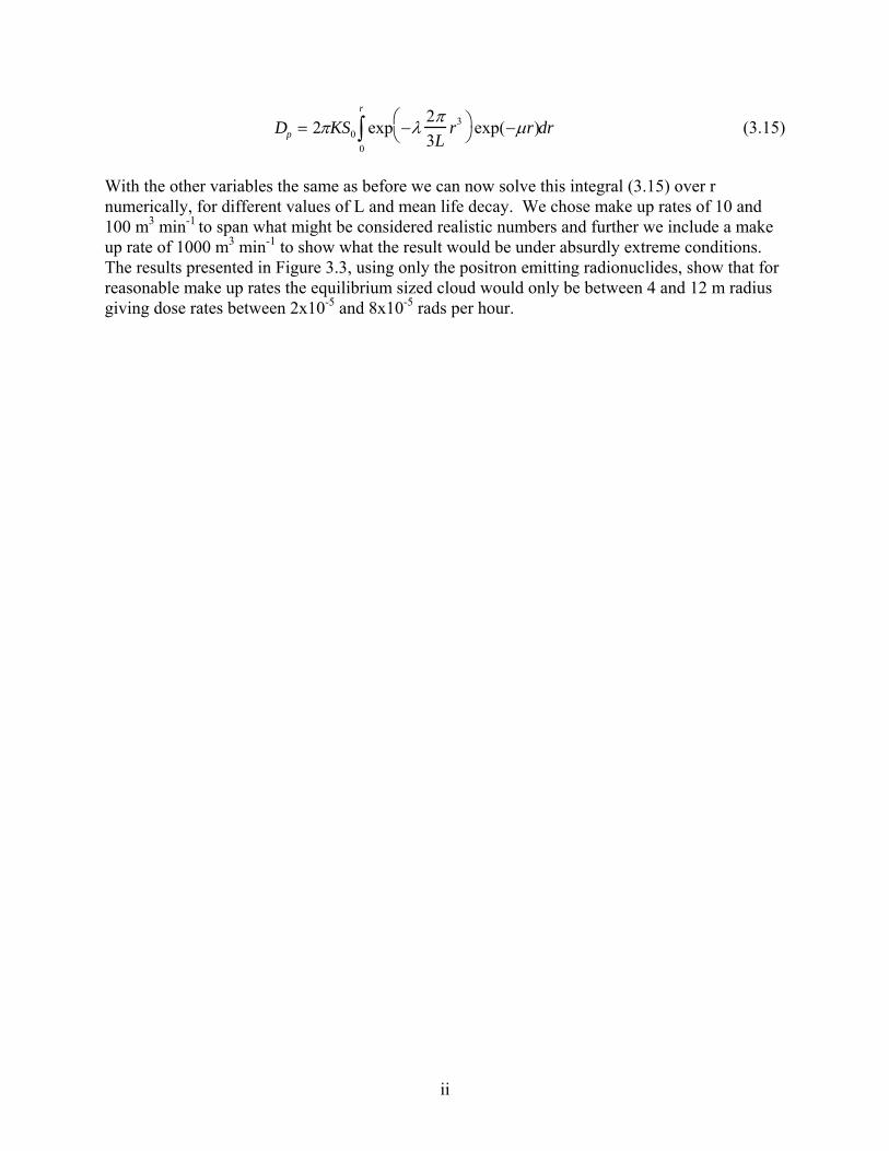
ii
Dp = 2πKS0 exp −λ2π3L
r3⎛ ⎝
⎞ ⎠ exp(−μr)
0
r
∫ dr (3.15)
With the other variables the same as before we can now solve this integral (3.15) over r numerically, for different values of L and mean life decay. We chose make up rates of 10 and 100 m3 min-1 to span what might be considered realistic numbers and further we include a make up rate of 1000 m3 min-1 to show what the result would be under absurdly extreme conditions. The results presented in Figure 3.3, using only the positron emitting radionuclides, show that for reasonable make up rates the equilibrium sized cloud would only be between 4 and 12 m radius giving dose rates between 2x10⁻⁵ and 8x10⁻⁵ rads per hour.

ii
Having established the lack of realism in the use of immersion dose rates let us now examine the limits for skin and eye exposure. The equation derived earlier for an infinite cloud for photons can be used with caution for betas where E β is the mean beta energy: Dβ ≈ 2.13 S E β (rad h-1per
μCi g-1). Converting to Bq/m3 and for an infinite cloud (which for betas is quite small), applying in this case a 0.5 factor for exposure to the skin being on one side only and a further correction for beta absorption in the basal layer of skin we obtain:
Dβ ≈ 2.3 x10⁻⁸ S E β exp (-μl) (radh-1per Bqm-3) (3.16) Now applying 70 μm as the approximate thickness of the basal layer of skin and μ in the above equation which varies with mean beta energy, we calculate the DAC using an annual limit of exposure of 50 rem (0.025 rem/hour) for skin. For the lens of the eye we must apply the thickness of the cornea and aqueous humor which we take to be 3000 μm, we calculate the eye DAC using an annual limit on exposure of 15 rem. The data for both the skin and eye are given in Table 3.6. From this table we note that the skin dose is limiting.
Table 3.6 Estimated DAC for Beta Irradiation of the Skin and Eye Using Correction for Basal Layer of Skin and a Correction for Cornea and Aqueous Humor for the Eye Nuclide E β
(MeV) Approx. μ (cm-1)
DAC - Skin (Bq/m3)
DAC - Eye (Bq/m3)
C-11 0.385 12 3.1E+06 3.1E+07 N-13 0.491 9 2.4E+06 1.0E+07 O-15 0.734 5.4 1.5E+06 2.2E+06 Ar-41 0.460 10 2.5E+06 1.4e+07
Table 3.7 Immersion DACs for Various Cloud Radii Together with DACs Where Skin
Dose is Limiting* (Positron Emitting Radionuclides) Radius of
Cloud r (m) DAC immers
WB only Skin Dose
(Bq m-3DAC
per 25 mradCrit Organ h-1)
(Bq m-3per C -11 N -13 O -15 2.5 mrad h-1) beta only beta+phot beta only beta+phot beta only beta+phot
1 2.9E+07 3.8E+06 3.8E+06 3.4E+06 3.4E+06 3.1E+06 3.1E+062 1.4E+07 3.2E+06 3.1E+06 2.6E+06 2.5E+06 2.1E+06 2.0E+063 9.6E+06 3.1E+06 3.0E+06 2.4E+06 2.3E+06 1.8E+06 1.7E+064 7.2E+06 3.0E+06 2.9E+06 2.4E+06 2.3E+06 1.6E+06 1.6E+065 5.8E+06 3.0E+06 2.9E+06 2.3E+06 2.2E+06 1.6E+06 1.5E+066 4.8E+06 3.0E+06 2.8E+06 2.3E+06 2.2E+06 1.5E+06 1.5E+067 4.1E+06 3.0E+06 2.8E+06 2.3E+06 2.2E+06 1.5E+06 1.5E+068 3.6E+06 3.0E+06 2.8E+06 2.3E+06 2.2E+06 1.5E+06 1.5E+069 3.2E+06 3.0E+06 2.8E+06 2.3E+06 2.2E+06 1.5E+06 1.5E+0610 2.9E+06 3.0E+06 2.7E+06 2.3E+06 2.2E+06 1.5E+06 1.4E+0611 2.6E+06 3.0E+06 2.7E+06 2.3E+06 2.1E+06 1.5E+06 1.4E+0612 2.4E+06 3.0E+06 2.7E+06 2.3E+06 2.1E+06 1.5E+06 1.4E+0613 2.2E+06 3.0E+06 2.7E+06 2.3E+06 2.1E+06 1.5E+06 1.4E+0614 2.1E+06 3.0E+06 2.6E+06 2.3E+06 2.1E+06 1.5E+06 1.4E+0615 2.0E+06 3.0E+06 2.6E+06 2.3E+06 2.1E+06 1.5E+06 1.4E+0616 1.8E+06 3.0E+06 2.6E+06 2.3E+06 2.1E+06 1.5E+06 1.4E+0617 1.7E+06 3.0E+06 2.6E+06 2.3E+06 2.0E+06 1.5E+06 1.4E+0618 1.6E+06 3.0E+06 2.6E+06 2.3E+06 2.0E+06 1.5E+06 1.4E+0619 1.6E+06 3.0E+06 2.5E+06 2.3E+06 2.0E+06 1.5E+06 1.4E+0620 1.5E+06 3.0E+06 2.5E+06 2.3E+06 2.0E+06 1.5E+06 1.4E+06

ii
Table 3.7 Cont. Immersion DACs for Various Cloud Radii Together with DACs Where Skin Dose is Limiting* (Ar-41)
Radius of Cloud r (m) DAC immers WB only DAC Skin Dose Crit Organ (Bq m-3 per 25 mrad h-1) (Bq m-3per Ar-41 Ar-41 2.5mrad h-1) beta only beta+phot
1 2.3E+07 3.6E+06 3.5E+06 2 1.1E+07 2.8E+06 2.7E+06 3 7.7E+06 2.6E+06 2.5E+06 4 5.8E+06 2.6E+06 2.4E+06 5 4.6E+06 2.5E+06 2.4E+06 6 3.9E+06 2.5E+06 2.4E+06 7 3.3E+06 2.5E+06 2.4E+06 8 2.9E+06 2.5E+06 2.3E+06 9 2.6E+06 2.5E+06 2.3E+06
10 2.3E+06 2.5E+06 2.3E+06 11 2.1E+06 2.5E+06 2.3E+06 12 2.0E+06 2.5E+06 2.2E+06 13 1.8E+06 2.5E+06 2.2E+06 14 1.7E+06 2.5E+06 2.2E+06 15 1.6E+06 2.5E+06 2.2E+06 16 1.5E+06 2.5E+06 2.2E+06 17 1.4E+06 2.5E+06 2.1E+06 18 1.3E+06 2.5E+06 2.1E+06 19 1.3E+06 2.5E+06 2.1E+06 20 1.2E+06 2.5E+06 2.1E+06
* the beta+photon dose is to the skin only - no whole body contribution included From this data we can see the cloud size where the skin dose becomes limiting, the case for O-15 gives the smallest DAC and could represent the most conservative result. Conclusions to be drawn from this simplified analysis is that for the radionuclides that are currently regulated on the basis of immersion in an infinite cloud, a more appropriate standard for accelerators is on the basis of the maximum size cloud that the accelerator vault can hold and then to consider whether the immersion dose is limiting or the skin dose. The tables provide some indication of the appropriate DAC to be used in given circumstances.
3.2 MEMBERS OF THE PUBLIC (OFF-SITE) AND ENVIRONMENTAL
A useful summary of requirements regarding the environmental aspects of radiation from CEBAF is given by Stapleton and Thomas (1990) and the following material selected from their paper sets out the regulatory aspects prior to that time:
The US Environmental Protection Agency [EPA] has the responsibility to develop guidance on radiological protection for all federal agencies. Such guidance is normally, although not necessarily, based upon recommendations of the International Commission on Radiological Protection [ICRP] and the National Council on Radiation Protection and Measurement [NCRP] and, after Presidential approval, implemented in the regulations of federal agencies.

ii
In addition to its statutory responsibilities to provide guidance on radiological protection, the EPA has several other responsibilities and powers regarding the regulation of radiation exposure. These are discussed below in the sections dealing with activated air and groundwater. It is worth commenting at this stage that the derivation of the air and water standards has been different from those used to derive radiological protection standards for external personnel exposure. Whereas the latter are derived from consideration of the hazard to human health, the derivation of the air and water standards have been driven by the concept of “best available technology.” These different approaches naturally lead to different upper limits to exposure of the general public for the three exposure routes. This is shown below in Table 3.8.
Table 3.8 Dose Equivalent Limits and Design Goals for the Different Exposure Routes Used to Control Environmental Exposure from CEBAF Operation (prior to
1989) Exposure Route Agency & Authority Annual Dose
(μSv/y)Equivalent Limit
(mrem/y)External Radiation DOE occasional exposure
to general population DOE prolonged exposure to general population CEBAF design goal at boundary
5000
1000
100
500
100
10
Airborne Releases EPA clean air actCEBAF design goal
250a
125 a
0.1Drinking Water (applied to groundwater)
EPA safe drinking water actCEBAF design goal close to accelerator
4010
41
a This limit was lowered to 100 μSv/yr (10 mrem/yr) in December 15, 1989 CFR (1989). It is also worth mentioning that although there is a potential for generating radionuclides in the air and groundwater around accelerators and for their subsequent release to the environment, typically the magnitude of any population exposure from this source is many times less than that from direct neutron exposure. Thomas and Rindi in 1979, concluded that the population dose equivalent from airborne radionuclides was at least an order of magnitude lower than from prompt radiation, and that no significant population exposure was to be expected from radionuclides induced in the ground surrounding accelerators. A more recent review by Goebel (1987) concerning the CERN LEP project similarly concludes that the radiological impact of the indirect pathways is insignificant. Discharge of Activated Air Under authority of the Clean Air Act, radioactive emissions into the air were limited (prior to 1989) so as to produce an annual dose equivalent no greater than 25 mrem (250 μSv) from this pathway. For new constructions approval had to be obtained from the EPA as an emission source subject to the National Emission Standards for Hazardous Air Pollutants [NESHAP] (CFR 1987a). This limit was changed in 1989 to 10 mrem/year (100 μSv/yr), and remains as such at the time of writing (CFR 1989). Detailed calculations were performed for the CEBAF accelerator and endstations and presented at the reviews discussed in §1.3. The first part of making an estimate of the effective dose equivalent to members of the critical members of the population surrounding the facility is to estimate annual radionuclide release

ii
rates from any given air release point. These release rates are then analyzed by some plume model which incorporates other variables such as wind direction and strength, height and diameter of release stack and volume of air released together with topological, agricultural and demographic aspects which when folded into various weather variables permits an estimate of population exposure via the various radiation pathways (inhalation, ingestion, immersion etc.). This latter calculation has been simplified to execute because the favored strategy is to utilize a computer package produced under the aegis of the US EPA. This computer program is rather easy to run and shortens an otherwise extremely lengthy and tiresome process (AIRDOS-EPA, CAP 88). The estimation of an annual release rate is alone somewhat complicated in that it requires estimates to be made of beam loss and consequential production of activated radionuclides but also some information about air ventilation rates. Ventilation rates are extremely important because if the ventilation rate was very low very little activated air would be released on the other hand if the ventilation rate was large then larger amounts of activation products would be released but this would not necessarily result in the maximum dose to the critical population because plume rise and concentration effects would reduce the individual dose rate. Calculations were performed in 1987 for activated air production in the accelerator tunnels and consequential release rates from which estimates of dose rates to critical members of the surrounding population were calculated by ORNL staff using the EPA code AIRDOS (Notification 1987, Stapleton 1987b). The calculated yields were based on intermittent operation of the accelerator with an assumption of negligible air release during accelerator operation. Only releases occurring during occupancy of personnel were included. This provided an extremely low result because releases were separated by long intervals of machine operation during which activation products reached a constant maximum saturation level. Hence this reduced the overall amount of radioactivity released. Reductions in concentration resulting from radionuclide decay during the release cycle also had the effect of reducing overall release figures. The release rates from the accelerator (then calculated) for the dominant radionuclides and the consequential estimate of dose to the critical members (most highly exposed) of the population as submitted for “start construction permit” are summarized in Tables 3.8a and 3.8b.
Table 3.8a Radionuclide Release Rates Calculated for the CEBAF Accelerator Emissions (Ci/yr)
H-3a Be-7 C-11 N-13 O-15 Cl-38b Ar-411.0E-02 5.4E-03 6.0E-03 1.4E-02 6.0E-06 3.5E-03 2.0E-02
a Includes tritium released from irradiated liquid He. b Includes contribution from Cl-39 release (3.3E-03 Ci). The results presented in Tables 3.8a and 3.8b are extremely small values and can be considered trivial when compared with the regulatory limit of 10 mrem/yr and the 1% monitoring value and so a construction permit was granted by EPA.
Table 3.8b Doses to the Nearest Resident at CEBAF Dose (millirem/yr)
Whole-bodyb Effectivec Lung Testes 5.3E-05 5.6E-05 6.4E-05 6.0E-05
a Nearest resident is 700 m west. Effective and organ doses are 50-year commitments. b Whole-body dose includes the dose from external pathways from all of the released radionuclides plus the internal
exposure contributions from H-3, C-11 and O-15 since they are considered to be whole body seekers. c Based on ICRP-30 organ weighting factors.

ii
A further submission was made to the EPA in 1994 as a “notification of start up” which included further estimates of radionuclide yields and consequent dose to members of the critical population (May et al 1994, Notification 1994). This submission presented calculations for the yields from the experimental halls and which again showed minimal results, these are presented in Tables 3.9a and 3.9b. The dispersion calculation was performed with the latest EPA code CAP-88 (which stands for Clean Air Act Assessment Package - 1988) computer model which estimates both dose and risk from radionuclide emissions to air. It allows users to perform full-featured dose and risk assessments to demonstrate compliance with CFR (1989). Wind directions, stabilities, and frequencies are considered to be the same for CEBAF as they are for Langley US Air Force Base. The 1992 STAR (STability ARray) formatted tabulation data from Langley AFB were obtained and used as input for meteorological calculations. Using the sum of all releases calculated, the program computes radionuclide concentrations in air, rates of deposition on ground surfaces, concentrations in food, and intake rates to people from ingestion of food produced in the assessment area. Estimates of the radionuclide concentrations in produce, leafy vegetables, milk, and meat consumed by humans are made by coupling the output of the atmospheric transport models with the U. S. Nuclear Regulatory Commission Regulatory Guide 1.109 terrestrial food chain models. Cl-38 and Cl-39 are summed and modeled as Br-84. The dose conversion factors are roughly equivalent and are, in fact, slightly conservative overall. The critical populations were found to be at distances somewhat greater than 500 m in a southerly direction; the 500 m distance was used as a conservative distance.
Table 3.9a Radionuclide Release Rates Calculated for the CEBAF End Stations Emissions (Ci/yr)
H-3 Be-7 C-11 N-13 O-15 Cl-38 Cl-39 Ar-415.1E-03 2.6E-03 5.1E-04 2.1E-03 2.2E-04 4.3E-05 7.8E-04 8.6E-04
Table 3.9b Effective Dose Equivalent at a Position 500 m to the South Used to Represent
the Critical Population Effective Dose Equivalent (mrem/yr)
Accelerator Endstations Accelerator + Endstations 1.7e-04 4.8e-05 2.1E-04
In a verbal communication between the DOE Site Office and EPA, it was agreed that no notification will need be filed with the EPA for any new construction or modification within the CEBAF facility as long as the effective dose equivalent, caused by all emissions from the new construction or modification, is less than 1% of the standard effective dose equivalent of 10 mrem/yr (Morgan 1996). Further, if the emissions of all radionuclides at CEBAF can contribute greater than 10% of the 10 mrem annual limit, then monitoring shall be in place. The facility must have periodic confirmatory measurements to verify the low emissions. Since the first NESHAPS notification in 1987, we have gained experience of operational conditions, and in particular, air flow and discharge rates from the tunnels and end stations. Thus, we have made a new assessment of the releases from both the accelerator and the end stations.

ii
The study of airflow rates in the accelerator tunnels show that there is not simple identifiable release points or operational sequencing that make possible the definition of precise releases both in time and location (Edwards 1997). Because of this, we have made a very worst case assumption that the total calculated radioactivity in air from the accelerator operations is released at low level (2 m above ground) at four points symmetrically placed around the accelerator as a continuous discharge throughout an operational year of 40 weeks. The result of this model calculation gives a result much larger than the original estimate by Stapleton (1987), who based the model on a staged release, i.e., no release during operation with beam on. However, even with the present very conservative assumptions, the result is still well below the monitoring level requirements for atmospheric discharges. For the end stations, Edwards (1997) ,showed that after blocking the return air path from the experimental halls to the accelerator tunnels, the release of air from the end stations could be considered negligible during beam on conditions. Thus, we may use the parameters given in May (1997). The radionuclide production data used in the calculation are given in Tables 3.5a and 3.5b, except for the case of Ar-41, which is derived for the specific geometry of the enclosures. The airflow and geometrics used in the calculation for all cases are given in Table 3.10. The build-up and decay of the various radionuclides are controlled by their various decay constants, and the release rate of the radionuclides to the environment is controlled by a constant similar to the decay constant. The basic radioactivation expression:
dNdt
= P − λN (3.17)
P = rate of formation (production) of N atoms,
the solution,
N(t) =Pλ
−λt1−e( ) (3.18)
gives the radioactivity after an irradiation time t: Q(t) = P −λt1−e( ) (3.19)
Introducing the loss of activated air by ventilation during irradiation introduces another constant λloss and equation (3.17) becomes:
dNdt
= P − decλ N − lossλ N (3.20)
λdec = radioactive decay const (s-1) λloss = ventilation const. R/V (s-1) R = ventilation rate (cm3 s-1) V = volume of hall (cm3) λeff = λdec + λloss

ii
Therefore, where radioactive decay and also loss by ventilation occur side by side, the radioactivity inside the enclosure at any time t is given by:
Q(t) = Pλdec
λeff
1 − e−λ eff t( ) (3.21)
which for long values of t becomes:
Q(t ⇒ ∞) = Pλdec
λeff
(3.22)
However, for the tunnel case, what we require is the emission value (released from the stack or other opening) for the activated radionuclides and, as a conservative approximation, we can say that the amount of radioactivity in the air passing out of the release at time t, point corresponds to the instantaneous radioactivity level in the room at time t, and hence, the activity so lost is given by:
Qloss = Pλdecλloss
λeff
1 − e−λ eff t( )0
T
∫ dt (3.23)
which becomes:
Qloss = Pλdecλloss
λeff2 Tλeff − 1− e− λeff T( )[ ] (3.24)
where T is 40 weeks (2.24E+07 sec).
Table 3.10 Accelerator Tunnels
length length cross-section accelerator 4300 ft 1310 m 10 ft x 13.5 ft BSY (stub) 260 ft 79 m 10 ft x 13.5 ft BSY (branch) 560 ft 171 m 7 ft x 7 ft tot volume V 6.43E+05 cu ft 1.82E+04 m3 air intake rate R 3000 cfm 85 m3min-1 1.42 m3 s-1 R/V 7.78E-05 s-1 mean radius 6.55 ft 2 m mean air path length 3 m cross-sect perim. 47 ft 14.3 m surface area 2.1E+05 sq ft 2.0E+04 m2 beam loss (neutron) 0.6 kW (based on 50% source term used for activation) beam loss (bremm) 0.06 kW (x10 red’n on account of shielding by magnets
etc) He in Cryomodulesa (Tritium Only) 10% release rate ~11 mCi 4.0E+08 Bq Halls C A radius 23 m 26.5 m height 18 m 19 m volume V 3.0E+04 m3 4.2E+04 m3

ii
air intake rate R 1000 cfm 1000 cfm R/V 1.6E-05 sec-1 1.13E-05 sec-1 air path length 27 m 26 m surface area 5925 m2 7576 m2 beam loss (neutron) 100W beam loss (bremm) 100W Beam Dump Caves volume 4.8E+03 cu ft 136.6 m3 (one cave only) radiation time 4.0E+05 min (air released after 40 weeks for maintenance) mean photon path 12 m mean neutron path 1 m surface area 265 m2 beam loss (neutron) 20 kW beam loss (bremm) 0.3 kW Helium Pipeb (Tritium Only – Optional) 40 wk release/yr ~5 mCi 1.8E+08 Bq (not incl. for vacuum pipe)a Details of calculation not included in this note, but result added to accelerator totals, Swanson (1986)
b Details of calculation not included in this note, but result added to end station totals, Stapleton (1990c) The rate of production of radioactive atoms is estimated, as mentioned above, by the use of the unit production term B, given in Tables 3.5a and 3.5b, for photoproduction and neutron spallation. The production term P (atoms per sec) is given by:
P = SLB (3.25)
S = beam power lost which results in production processes in air L = path length threaded by the radiation
For the thermal neutron activation of Ar-40 to give Ar-41, we must use a different production term for P. The thermal flux in a concrete enclosure has been given by Patterson (1958) as:
Qth =1.25Qf
a (3.26)
a = surface area of the enclosure (cm2) Qf = fast neutron yield
Making the approximation that the neutron yield from targeted electron beams is 1012 kW-1, the production P of Ar-41, is given by:
P = 1.25 ×10¹² SVa
NA
Afwσρ (3.27)
S = source term (kW) V = volume of enclosure (cm3) A = atomic weight of target atom (Ar-40) NA = Avogadro’s No

ii
fw = weight fraction of target atoms in the atmosphere (1.3 10-2) σ = thermal neutron capture cross section (610 mb) ρ = density of air (0.0012 g cm3)
substituting:
PAr − 41 =1.25 ×10¹² SVa
6.02 ×10²³
401.3 ×10−2610 ×10−270.0012
hence:
PAr − 41 =1.79 ×10⁵ SVa
(3.28)
Therefore, by combining equation (3.24) with (3.25), we obtain the photonuclear and neutron spallation production, and with equation (3.28), we obtain the thermal neutron activation of Ar-40. The results of this calculation is given in Table 3.11
Table 3.11 Annual Releases from the Accelerator (Release height 2 m) Nuclide Direct from Accel
Operation Addition from
Liq He Sum of all Releases
H - 3 1.2E+06 4.0E+08 4.0E+08 Be - 7 3.0E+07 3.0E+07 C - 11 1.7E+10 1.7E+10 N - 13 5.1E+10 5.1E+10 O - 15 3.3E+10 3.3E+10 Cl - 38 1.8E+08 1.8E+08 Cl - 39 2.1E+09 2.1E+09 Ar - 41 1.1E+10 1.1E+10
total (Bq/year) 1.1E+11 4.0E+08 1.1E+11 total (Ci/year) 3.1 0.01 3.1
Because the release of activated air is much more controlled in the case of the end stations, we adopt a staged release as discussed by May et al. (1997). In effect, we assume a three day operational cycle with zero release followed by a one day shut down during which the air was exhausted at 1000 cfm for each of the end stations. The equations describing this process are as follows:
growth of radioactivity: Qup = P 1− e− λdec tup( ) (3.29)
loss during shutdown:
Qloss = Qt upλloss 1 − e−λ eff tdn( )dt
0
T
∫ (3.30)
Qloss = Qt up
λloss
λeff
1 − e−λeff T( )≈ Qtup
λloss
λeff
(3.31)

ii
Thus, for a 3 day up period followed by a one day down period, we require to multiply the release by 70 to give the year total (40 weeks/4 days) so the annual loss is given by:
Qloss ≈ 70P 1− e− λdec tup( )λloss
λeff
(3.32)
Additional contributions to the releases from the end stations arises from an assumed 40 week irradiation of the air in the beam dump tunnel followed by a release at the end station air make up rate, plus some additional contribution (only from end station C) from activation of helium gas used in the dumpline; again, the assumption is 40 weeks running.
Table 3.12 Annual Releases from the End Stations (stack height 15 m)
Nuclide Direct from E/S Operation
Addition from Dump Tunnel
Addition from He Tube
Sum of all Releases
H - 3 1.8E+06 1.4E+07 1.78E+08 1.9E+08 Be - 7 3.7E+07 8.9E+07 1.3E+08 C - 11 6.5E+07 3.0E+06 6.8E+07 N - 13 2.5E+08 5.8E+06 2.6E+08 O - 15 2.7E+07 7.0E+05 2.8E+07 Cl - 38 5.2E+06 1.0E+05 5.3E+06 Cl - 39 9.5E+07 1.8E+06 9.7E+07 Ar - 41 7.4E+07 2.1E+07 9.5E+07
total (Bq/year) 5.5E+08 1.4E+08 1.8E+08 6.9E+08 total (Ci/year) 0.015 0.004 0.005 0.023
The results of running CAP-88 for both the latest accelerator data together with the end station results are summarized in Table 3.13. The full report on both these dispersion calculations is filed under c:\cap88pc2\datasets.
Table 3.13 Effective Dose Equivalent at a Position 500 m to the South Used to Represent the Critical Population Based on Recent Data from Tables 3.11 & 3.12
Effective Dose Equivalent (mrem/yr) Accelerator End Stations Accelerator + End Stations4.06E-03 4.66E-05 4.1E-03
They represent the highest calculated total effective dose equivalent to an individual from normal CEBAF operations, based on the annual yields calculated in this note. As discussed earlier, the annual limit of exposure from airborne radioactivity is set by the US Department of Energy at 10 mrem. The calculated result is 0.04% of the annual limit of exposure, and 4% of the level where annual real-time monitoring would be required. Ground and GroundWater Activation
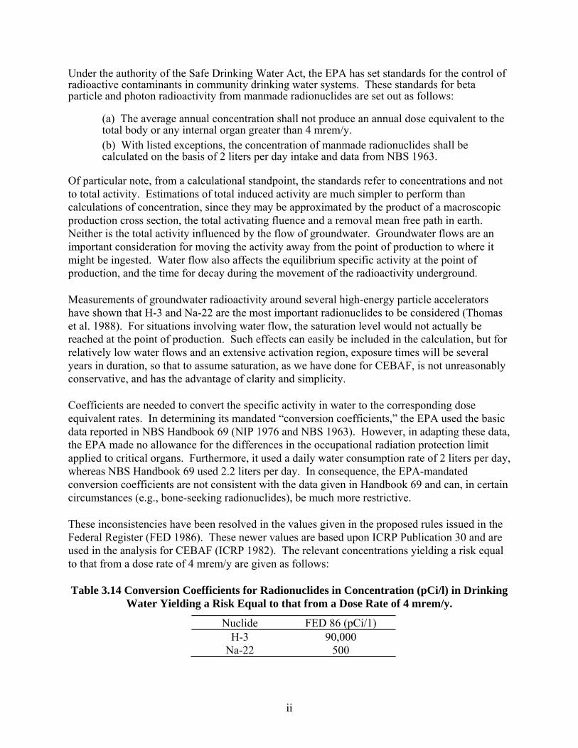
ii
Under the authority of the Safe Drinking Water Act, the EPA has set standards for the control of radioactive contaminants in community drinking water systems. These standards for beta particle and photon radioactivity from manmade radionuclides are set out as follows:
(a) The average annual concentration shall not produce an annual dose equivalent to the total body or any internal organ greater than 4 mrem/y. (b) With listed exceptions, the concentration of manmade radionuclides shall be calculated on the basis of 2 liters per day intake and data from NBS 1963.
Of particular note, from a calculational standpoint, the standards refer to concentrations and not to total activity. Estimations of total induced activity are much simpler to perform than calculations of concentration, since they may be approximated by the product of a macroscopic production cross section, the total activating fluence and a removal mean free path in earth. Neither is the total activity influenced by the flow of groundwater. Groundwater flows are an important consideration for moving the activity away from the point of production to where it might be ingested. Water flow also affects the equilibrium specific activity at the point of production, and the time for decay during the movement of the radioactivity underground. Measurements of groundwater radioactivity around several high-energy particle accelerators have shown that H-3 and Na-22 are the most important radionuclides to be considered (Thomas et al. 1988). For situations involving water flow, the saturation level would not actually be reached at the point of production. Such effects can easily be included in the calculation, but for relatively low water flows and an extensive activation region, exposure times will be several years in duration, so that to assume saturation, as we have done for CEBAF, is not unreasonably conservative, and has the advantage of clarity and simplicity. Coefficients are needed to convert the specific activity in water to the corresponding dose equivalent rates. In determining its mandated “conversion coefficients,” the EPA used the basic data reported in NBS Handbook 69 (NIP 1976 and NBS 1963). However, in adapting these data, the EPA made no allowance for the differences in the occupational radiation protection limit applied to critical organs. Furthermore, it used a daily water consumption rate of 2 liters per day, whereas NBS Handbook 69 used 2.2 liters per day. In consequence, the EPA-mandated conversion coefficients are not consistent with the data given in Handbook 69 and can, in certain circumstances (e.g., bone-seeking radionuclides), be much more restrictive. These inconsistencies have been resolved in the values given in the proposed rules issued in the Federal Register (FED 1986). These newer values are based upon ICRP Publication 30 and are used in the analysis for CEBAF (ICRP 1982). The relevant concentrations yielding a risk equal to that from a dose rate of 4 mrem/y are given as follows: Table 3.14 Conversion Coefficients for Radionuclides in Concentration (pCi/l) in Drinking
Water Yielding a Risk Equal to that from a Dose Rate of 4 mrem/y.
Nuclide FED 86 (pCi/1) H-3 90,000
Na-22 500

ii
For combined concentrations of H-3 and Na-22, the dose rate is given by:
H(mrem/yr) =22Na[ ]0.125
+3 H[ ]
22.5 (3.23)
where the concentrations of H-3 and Na-22 are in pCi cm-3.
In implementing its regulations, the EPA can delegate to the separate states. Thus, in its requirements for the establishment of water quality standards, the EPA requires that states, “develop and adopt a statewide anti-degradation policy and identify the methods for implementing such a policy. . .” (CFR 1987b). General guidelines for minimum compliance are given, but individual states may adopt more restrictive policies. The Commonwealth of Virginia has adopted an anti-degradation policy for groundwater which includes the following statement (Virginia 1988):
"Anti-degradation Policy for Groundwater If the concentration of any constituent in groundwater is less than the limit set forth by groundwater standards, the natural quality for the constituent shall be maintained; natural quality shall also be maintained for all constituents, including temperature, not set forth in groundwater standards. If the concentration of any constituent in groundwater exceeds the limit in the standard for that constituent, no addition of that constituent to the naturally occurring concentration shall be made. Variance to this policy shall not be made unless it has been affirmatively demonstrated that a change is justifiable to provide necessary economic or social development, that the degree of waste treatment necessary to preserve the existing quality cannot be economically or socially justified, and that the present and anticipated uses of such water will be preserved and protected."
Strictly interpreted, such a policy requires authorization for any release anywhere no matter how small. The same authority has also promulgated groundwater standards for radionuclide contamination as follows (Virginia 1988):
Radioactivity Total Radium (Ra-226 & Ra-228) 5 pCi/l Radium 226 3 pCi/1 Gross Beta Activity* 50 pCi/l Gross Alpha Activity 15 pCi/l (excluding Radon & Uranium) Tritium 20000 pCi/1 Strontium-90 8 pCi/1 Manmade Radioactivity - Total Dose Equiv.** 4 mrem/y
* The gross beta value shall be used as a screening value only. If exceeded, the water must be analyzed to determine the presence and quantity of radionuclides to determine compliance with the tritium, strontium, and manmade radioactivity standards. ** Combination of all sources should not exceed total dose equivalent of 4 mrem/y.”

ii
To ensure compliance with the standards requirement by the State Water Control Board of Commonwealth of Virginia, sampling wells were established on the CEBAF site. These wells were designated “A,” “B,” and “C” according to the distances from the accelerator. The “A” wells were located about 3 m to 5 m from the accelerator concrete shield wall, and the “B” wells some 10 m - 20 m away; the “C” wells were located near the site boundary. On the basis of sampling and analysis protocols for each ring of wells, the following standards for groundwater quality were established for CEBAF (Virginia 1989):
“The following ‘action levels’ are established for the “A” wells: Tritium 5000 pCi/l Manmade radioactivity 1 mrem/yr The following limitations are established for the “B” wells: Tritium 5000 pCi/l Manmade radioactivity 1 mrem/yr At no time shall the ‘C’ wells exceed the background levels established in accordance with pre-operational background measurements made using an EPA-methodology with stated statistical confidence limits.”
Levels of induced activity in the ground and groundwater, for any given beam loss, can be limited by the use of underground shielding. The use of pumped gravel underdrains or the use of waterproof membranes to prevent the groundwater from entering regions of high activating flux have been considered and rejected on the grounds of unreliability or increased post-operational work. The most favored solution, which we have adopted at CEBAF, is to use solid concrete. In order to derive the concentration of Na-22 and tritium in the groundwater at the highest location - just outside the concrete underground shielding - it is necessary to calculate the activating neutron fluence (Stapleton 1987a, 1989c). The energy thresholds for the activation are in the region of 20 - 30 MeV so therefore, we use the shielding equation given in § 2.0 Shielding method but restrict the terms used to the HEN and MID terms because of the threshold energy considerations. The resultant estimate of dose equivalent outside the shielding is converted to the activating fluence rate using a conversion coefficient based on measured observations elsewhere (Gilbert et al. 1968). This coefficient was chosen because it represented the carbon-11 monitor flux through a concrete shield which is a reasonable approximation, and with a 6 GeV (the beam energy was set at 6 GeV at the time this calculation was performed) upper energy cut-off gave a neutron yield slightly greater than the simplistic but unreal 1/E spectrum ( E.dφ dE = const ) with the appropriate energy threshold and cut-off, so frequently adopted. The coefficient used was:
1 mrem h-1 ≅ 2.3 n cm-2 s-1
The fluence rate can then be obtained from the shielding expression:
φ = HENe−100 tρc 120 + MIDe−100 tρc 55[ ]2.3 × 10³ (n cm−2 s−1 at one meter) (3.24)

ii
The quantities have already been defined earlier except for ρ c which is used for the density of concrete shielding.

ii
The expression for generating the concentration of mixture of radionuclides is given by:
Si =27φΣ iε iρw
fw(pCi cm−3) (3.25)
where Si = specific volume activity of the groundwater for nuclide i, φ = activating neutron fluence rate (n cm-2 s-1), Σi = macroscopic cross section for the production of nuclide i (cm2g-1), εI = water extractable fraction of the radionuclide i, f w = water fraction in the ground, ρ w = density of water (gcm-3), 27 = coefficient that converts Bq to pCi.
We can combine equations (3.23), (3.24) and (3.25) to give the dose rate for Na-22 and H-3:
H(mrem/yr) =27φρw
fw
Σε( )Na− 22
0.125+
Σε( )H −3
22.5⎡ ⎣ ⎢
⎤ ⎦ ⎥ (3.26)
The cross section and other data used to calculate groundwater activity is given in the following Table 3.15 (Borak et al. 1972):
Table 3.15 Cross-Section Data for Estimating H-3 and Na-22 Concentration in Ground Water
Radionuclide Σi Ground + Water(cm2 g-1)
εi Σi εi 27ρw/fw
H-3 7.7 x 10⁻⁴ 1.0 8.0 x 10⁻² Na-22 2.0 x 10⁻⁴ 0.15 3.1 x 10⁻³
Using this data, the fluence rate which would produce H mrem/yr (groundwater) is given by:
φ =H(mrem/yr)0.125 × 22.5
22.5 × 3.1 ×10−3 + 0.125 × 8.0 ×10−2 ≅ 35.3H (3.27)
From this data we also note that for the 1 mrem/yr screening value – at the “A” wells – we derive a concentration of 2.8 pCi cm-3 for H-3 together with 0.1 pCi cm-3 for Na-22, we note that the screening value given separately for H-3 is 5 pCi cm-3 which is greater than the 2.8 pCi cm-3 value; therefore, the 1 mrem/yr is the determining quantity for groundwater standards at the “A” wells. While it is recognized that the “A” wells are located a few meters away from the accelerator shield walls, nevertheless, the shielding was designed approximately to “A” well standards such that the calculated concentration just outside the shield wall would be approximately at the 25% limit value prescribed as a screening value at the “A” wells. The following data given in Table 3.16 summarizes these calculations:

ii
Table 3.16 Calculated Thicknesses of Concrete Specified to Protect the Ground Water
Linac and Switchyard Tunnels assumed beam loss accelerator tunnel switchyard tunnels
0.5 W/m (APARS 1988) 0.25 W/m (see footnote)
distance from line source to tunnel wall (for groundwater protection – line source assumed located at center of tunnel) accelerator tunnel switchyard tunnels
4.5 ft (1.4 m) 3.5 ft (1.07 m)
density of concrete walls 147 lb/cu.ft (2.35 g cm-3) required thickness to achieve design goal accelerator tunnels switchyard tunnels
1.76 ft (53.8 cm) 1.89 ft (57.7 cm) 1.43 ft (43.6 cm)
actual thickness specified accelerator tunnels switchyard tunnels
1 ft 9 in 1 ft 9 in
Note: Because the beam is split into the branched tunnels in the switchyard, the loss term is halved to calculate groundwater activation around the switchyard tunnels, the required wall thickness for both loss terms (0.5 W/m and 0.25 W/m) is given in the table. However, the wall thickness specified is the same for both switchyard and accelerator tunnels for practical considerations in construction. The tunnel wall specified for shielding corresponds approximately with the thickness required for construction purposes, so the additional cost for groundwater shielding is not large. This is not the case for the beam dumps where it was necessary to include extremely thick underground concrete shielding. In order to optimize the cost of this beam dump shielding, a careful analysis was made of the various shielding recipes for very thick shields (~4 m) and the appropriate average beam power deposited to be used for design purposes. The assumed average power deposited in each of the dumps for end stations A and C, taking into consideration experimental hall and accelerator utilization, together with a likely mix of experiments (some of which would use beam powers much lower than maximum), would be 200 kW (6.3 109 kJ yr-1). For end station B, which has a much lower beam duty, the average power deposited was assumed to be 20 kW (6.3 108 kJ yr-1). A discussion of these power deposition parameters are set out in Stapleton (1989d). Studies of shielding methods showed that the SLAC recipe gave the most conservative results (i.e., required the thickest shielding); other recipes including an extreme case (not confirmed by later work) based on contemporary calculations for the CERN Compact LInear Collider (CLIC) project suggested that about 3 ft less shielding would be appropriate (Höfert 1988). Thus, we calculated the shield thickness needed for halls A and C dumps using various shielding recipes with the results ranging from 13 ft (at the low extreme) to 16 ft at the other. A discussion of these results, with an expert review panel, resulted in the conclusion that the 15 ft thickness would be appropriate, taking into consideration the conservatism of the SLAC result, and at the

ii
other end, the unverified data presented by Höfert (CEBAF 1989). The thicknesses specified are given in Table 3.17. The review panel cited above, also supported a proposal by CEBAF to make measurements through the thickness of concrete shielding to verify the actual choice of cross-section used for the neutron transport (CEBAF 1989). To further this proposal, plastic pipes were inserted during the concrete pour which could be used to place the dosimeters. It is expected that this work will take place during the next year or so. In addition, recent studies of groundwater activation using the event generator DINREG and the transport code GEANT in which the switchyard tune-up beam dump was modeled, using the actual as-built dimensions, including installed iron shielding (Degtiarenko 1997). The production cross sections and other parameters used for determining groundwater concentration were the same as for earlier calculations. The result of this calculation was approximately a factor two higher than the result using the earlier analytical method (May 1997). This result provides good confirmation that the methods developed and used for the underlying design of CEBAF are substantially correct. It should be noted that DINREG/GEANT has not been fully verified by experiment, but comparisons with existing data indicate that the result can be expected to be accurate to within a factor 2 or 3.
Table 3.17 Calculated Thicknesses of Concrete Specified to Protect the Ground Water
Beam Dumps (Halls A, B and C) assumed beam loss end stations A & C end station B
200 kW (6.3 109 kJ yr-1) 20 kW (6.3 108 kJ yr-1)
distance from line source to tunnel wall (loss point assumed located on centerline)
1.0 m
density of concrete walls 147 lb/cu.ft (2.35 g cm-3) target material Al required thickness to achieve design goal (actual thickness specified) end stations A & C end station B
15 ft (lateral) 18 ft (end-on) 12.5 ft (lateral) 15 ft (end-on)
Discharge of activated water Jefferson Lab requires the use of several cooling water systems. The systems are conveniently grouped into two categories. Those which cool components located principally outside the accelerator enclosure such as RF systems and related power supplies or are secondary cooling loops to systems located inside the accelerator enclosure, and those which cool components located inside the accelerator enclosure and consequently are exposed to an activating flux directly (as in beam dump cooling) or indirectly (as in magnet cooling).

ii
All systems are routinely sampled by the Radiation Control Group to verify system integrity, to verify the absence of or presence of radioactivity, and to determine the radionuclide inventory. Systems exposed to a direct activating flux which develop appreciable amounts of radioactivity have been designed with containments to prevent inadvertent release to the environment and, where applicable, with shielding to lower the radiation dose associated with the presence of radioactivity in the system. The Jefferson Lab DOE Site Office holds two permits. One is through the Hampton Roads Sanitation District which allows Jefferson Lab to release small amounts of beam dump cooling water to the sanitary sewer after careful analysis (Hampton 1995). The limits on this discharge are found in the Commonwealth of Virginia Rules and Regulations for Ionizing Radiation and are consistent with federal regulations found in 10 CFR 20. This permit is under revision to allow small quantities of water from other sources to be processed to the sanitary sewer under the existing permit limits.

ii
The other permit (Virginia Pollution Abatement Permit - VPAP ) is discussed in the previous section, Ground and Groundwater Activation, which gives an historical perspective. In 1995, Jefferson Lab hired a specialist local engineering company, Malcolm-Pirnie, to conduct a review of the post construction hydrogeology, evaluate the groundwater gradient, and model the flow characteristics, in order to determine the appropriate values and confidence limits for the site boundary wells, and make general recommendations regarding the planned revision of the VPAP. The result of the modeling indicated several plausible scenarios where potentially activated groundwater could be captured by this de-watering system and pumped to the surface (Malcolm-Pirnie 1995). (The structural design requires that a system below the end station floors collect and drain off the groundwater to the surface channel system). With the added possibility of a potentially activated surface release, the Commonwealth of Virginia decided to issue a Virginia Pollution Discharge Elimination System (VPDES) Permit, which established action levels and permit limits for radioactivity in both the groundwater and surface water discharge (Virginia 1994). This permit was issued in 1996 prior to the dedication of Jefferson Lab. Several additional changes were made in the new permit including the phased installation of six new monitoring wells, and the reassignment of sampling parameters and sampling frequency based on the new understanding of the post construction hydrogeology. Action levels and limits initially identified in the VPAP remain substantially the same for the VPDES Permit with respect to groundwater. Several minor changes occurred in the radionuclides chosen for analysis and the corresponding limits identified in the permit. Surface water radionuclide limits are set to the EPA Drinking Water Standard (CFR 1987c). The net result is a ground and surface water monitoring program tailored to Jefferson Lab. It is robust enough to detect radioactivity in the surface or groundwater, allow the Lab management time to modify operations and mitigate the situation, and maintain the quality of the groundwater on and off the accelerator site. Consequently, no changes are necessary to support operations at increased electron beam energy.
3.3 STORAGE AND RELEASE OF ACTIVATED MATERIALS
Reference material cited in this section is contained in the CEBAF Radiation Protection Program Plan which should be consulted for details of all radiation control procedures (CEBAF 1995). Removal of potentially activated material from the accelerator enclosure: All materials taken out of the tunnel are required to be surveyed for radioactivity by a member of the Radiation Control Group (RCG) or placed in an approved storage location after a radiation survey by a trained staff member. Materials removed form the storage location are required to be surveyed by a member of the RCG. Controls on work with activated components: Components that have been activated to a detectable level (approximately twice background in a low-background area) are tagged as Radioactive Material. The tag explicitly states that no activities involving cutting, grinding, welding, etc., or disposal, are to be done without RCG review. In all cases, the work progresses

ii
under a Radiation Control Operating Procedure (RCOP) and/or a Radiation Work Permit (RWP). The shavings from the operation are gathered and retained for analysis and proper disposal. Since this activity is controlled for any work on an activated component, there are no environmental effects. When appropriate, RCG staff will also survey for radioactive contamination. Contamination from machine operations (discussed in depth in 3.1 above) is typically limited to the external surfaces and is either removed completely (decontaminated) before the component is taken from the accelerator enclosure or is carefully tracked and handled only by the Radiation Control Group. Any materials used for decontamination are also retained as radioactive material. Reuse or disposal of radioactive materials: Items identified as radioactive materials or activated components are either temporarily stored for decay or disposed of as low level radioactive waste in accordance with all applicable federal regulations. The choice of retention for decay or disposal depends on the type of radioactivity contained in the material. Temporary storage sites for activated components or radioactive material are carefully chosen and monitored. The contents of these storage sites are packaged in a way which prevents degradation. The contents are inventoried semiannually. There are no environmental effects from this activity. Activated material which has been reworked is typically taken back to the accelerator enclosure and reinstalled, or disposed of as radioactive waste. Activated material may be shipped, in accordance with all applicable regulations, to another facility with a DOE, NRC, or State regulated program of radioactive material control. In this case, the Radioactive Materials tag remains on the item at all times and the shipping information contains the legally required data. Release of materials: Materials which have been surveyed by RCG staff and are found to be non-radioactive are marked with a release tag. The tag indicates that the materials have been surveyed, are suitable for release from radiologically controlled areas and unrestricted use on site. Except for additional survey requirements, which the RCG may invoke in special circumstances, (such as verifying that contamination is not present on internal parts of an item), the release criteria for unrestricted use off site are virtually the same. There are other control measures used by the RCG, i.e., all trash cans staged in radiologically controlled areas are surveyed by a member of the RCG before disposal; filters used in systems not normally associated with radioactive materials are surveyed before disposal; and samples are taken of liquids and aqueous material to verify the absence of radioactivity in excess of applicable limits. To conclude, these procedures form an effective program of activated material control at Jefferson Lab for preventing any loss of activated material to the population or the environment.

ii
4.0 OZONE PRODUCTION One of the major products of radiolysis of air, of concern from a health and safety standpoint, is ozone. Other products produced in parallel, such as the oxides of nitrogen, are more of concern when under humid conditions, the resulting acid compounds can cause serious corrosion problems to unprotected accelerator components. Ozone being a potential health concern will be considered in this section. However, any calculation can only be very approximate and provides only some order of magnitude estimates of potential ozone concentrations in accelerator vaults. The equations used are basically similar to those discussed in §3.0 Discharge of Activated Ai,r which define a similar production term and decay, and loss constants. The various production parameters are given in Table 4.1 and are taken from Swanson (1979b).
Table 4.1 Ozone Production at Electron Linacs after Swanson (1979b) Gas TLV (ppm) G-value in Air
(molecules per 100 eV)
Decomposition Time
Assumed (min) ozone O3 0.1 7.4 - 10.3 50 nitrogen dioxide NO2 5 (4.8) - The derivation of a production term is based on the average collisional stopping power of electrons of ≈ 2 MeV cm2 g-1, Swanson advocates using a G-value of 10.3, so we can derive an expression for the production of ozone:
p =60(s / min)
1.602 × 10⁻¹⁹(e)10.3(Gval)100(eV )
22.4(l / gmol)6.02 ×10²³(NA )
2 ×10⁶(eV )0.00122(ρ)100(cm / m)
which results in an expression the same as the one Swanson derived:
p ≈ 350 × I × L (4.1)
where p = ozone production in liters per minute I = electron current in ampere L = air path in meters
This production expression is for an electron beam; however, any beam loss results in the beam striking some component which greatly multiplies the number of electrons due to showering. Swanson discusses this effect and argues that the greatest enhancement arises from an “optimum” thickness of material struck by the beam. This thickness is related to the shower maximum, and in the worst cases, can give rise to an enhancement factor of about 10. For our case, we choose an enhancement factor of 5, which we consider reasonably conservative.

ii

ii
We can now utilize the expressions derived previously for estimating the concentration build-up in the experimental halls and tunnels:
C(t) =5P
Vλeff
1 − e−λ eff t( ) (4.2)
hence:
C(t ⇒ ∞) =5P
Vλeff
(4.3)
We can now substitute the values for the mean decomposition time of 50 minutes (λdec= 3.3 10-4 s-1) and the tunnel air turnover time (λloss= 7.78 10-5 s-1) giving λeff = 4.1 10-4 s-1. The tunnel volume is taken to be 1.82 104 m3 (Table 3.10). For the production term, we assume an intermediate beam energy, say, 2 GeV and, from our loss term of 0.06 kW, we derive an electron current of 3 10-8 A. The air path we have already established as 3 meters. We can now proceed to estimate the equilibrium concentration of ozone in the tunnels:
Caccel = 535060
3.0 ×10⁻⁸ 31.82 ×10⁴ 4.1× 10−4 = 3.5 × 10⁻⁷ liters/m3( )≈ 4 × 10⁻⁴ ppm( )
This result is clearly well below the TLV and does not constitute an occupational or environmental problem. Repeating this calculation for end station C again using the values we adopted for air activation, (L = 27 m, V = 3.0 104 m3, beam loss 0.1 kW, which results in a beam current of 5 10-8 A, based on a beam energy of 2 GeV), and remembering that there is no air loss during beam on operations so that equation (4.3) becomes:
C(t ⇒ ∞) =5P
Vλdecf
(4.4)
Chall = 4 ×10⁻⁶ liters/m3( ) = 4 ×10⁻³ ppm( )
To conclude this section, we can say that on average, the end stations are likely to experience higher concentrations of ozone (during beam on periods) by about a power of ten over the accelerator tunnels, but even in the end stations this concentration is about 25 times lower than the TLV given by Swanson, and furthermore, because of ozone decay and ventilation loss when the beam is off, the estimated levels cannot be sustained for long, and are thus, unlikely to become an occupational or an environmental hazard. It must, however, be pointed out that these calculations can only be approximate because of the many assumptions made, and they only apply to estimated average conditions and it is quite likely that losses very much higher could be experienced for short periods. These would result in instantaneous concentrations much higher than estimated. Furthermore, the calculation also assumes that complete air mixing occurs inside the vault. This is certainly not the case in the end stations where stratification of the air can occur resulting in regions of much higher concentration.

ii
5.0 CONCLUSIONS The main purpose of this tech note is to show that, provided the approved 1 MW safety envelope is maintained, increasing beam energy to 8.0 GeV will give rise to no additional radiation control problems. All the important radiation control aspects have been reviewed and many calculations repeated to demonstrate that the facility was designed to proper safety standards. We examined the provisions for dealing with prompt radiation and established that the systems for access control and beam safety would not require any changes or modifications for the energy increase. This also applied to stoppers where it was shown that the slight change in position of the shower maximum would be insignificant. We also showed that the shielding requirements scaled with power, and hence no additional shielding, would be required to protect occupational workers. With regard to skyshine, we showed that provided the power was restricted, then the effect of increased energy would result in a slight reduction in fence post radiation. The quantity of induced radioactivity has been shown also to scale with beam power so that an increase in beam energy from 4 GeV to 8 GeV, with a corresponding decrease in beam current so as to keep below the mandated safety envelope power of 1 MW, is not expected to show any significant increase in induced radioactivity. The production of ozone has been shown to be a function of beam current loss so that providing the power loss remains the same for all energies, then the beam current loss will reduce and hence the amount of ozone produced will reduce. We have shown that measurements taken since the facility has been operational have fully demonstrated the integrity of the original calculations covering all aspects of radiation safety.
6.0 ACKNOWLEDGMENTS The authors would like to thank the following people for their help in contributing to this Tech Note: Jim Boyce, Zach Edwards, Linda Even, Kelly Mahoney, Barbara Morgan, and Christine Hummel for her editorial help.

ii
7.0 REFERENCES AIR; AIRDOS-EPA: “A Computerized Methodology for Estimating Environmental
Concentrations and Dose to Man from Airborne Releases of Radionuclides,” US Department of Commerce, Nat Tech Inf Service, PB80, 147838, (1979).
APARS; Report of the Advisory Panel on Accelerator Radiation Safety in the Continuous Beam
Accelerator Facility, April 7, (1988). APARS; Report of the Advisory Panel on Accelerator Radiation Safety in the Continuous Beam
Accelerator Facility, December 6, (1989). Barbier, M.; “Induced Radioactivity,” Amsterdam: North Holland Publishing Company,
Chapter 1, (1969a). Barbier, M.; “Induced Radioactivity,” Amsterdam: North Holland Publishing Company,
pp 223-224, (1969b). Barbier, M.; “Induced Radioactivity,” Amsterdam: North Holland Publishing Company,
p 36 and p 317, (1969c). Barbier, M.; “End Station Roof Shielding,” Technical Report - MMB-35; 25 May (1987);
also CEBAF TN-0061, appendix 3.2.1, (1987). Borak, T. B., Awschalom, M., Fairman, W., Iwami, F. and Sedlet, J; “The Underground
Migration of Radionuclides produced in soil near high-energy Proton accelerators,” Health Physics 23, 679 (1972).
CEBAF; Workshop on Radiation Safety, held April 7-9, 1986 at CEBAF.
CEBAF TN-0058, (1986). CEBAF; Radiation Control Review, held June 16 - 18, 1987 at CEBAF.
CEBAF TN-0061, (1987). CEBAF; End Station Radiation Control Workshop, held September 26 - 28, 1988 at CEBAF.
CEBAF TN-0095, (1988). CEBAF; Radiation Protection Program Plan, (1995). CEBAF; Review of the Radiological Aspects of the Conceptual Design Report for the CEBAF
End Stations and Switchyard, held August 15 - 17, 1989 at CEBAF. CEBAF TN-0174, (1989).
CFR; Code of Federal Regulations, Protection of the Environment, 40, Chapter 1, Part 61,
Subparts A & H §61.92 Emission Standards. July 1, (1987a).

ii
CFR; Code of Federal Regulations, Protection of the Environment, 40, Chapter 1, Part 131.12,
July 1, (1987b). CFR; Code of Federal Regulations, Protection of the Environment, 40, Chapter 1, Part 141.16,
July 1, (1987c). CFR; Code of Federal Regulations, Protection of the Environment, 40, Chapter 1,
Part 61, sub part 2, final rule, December 15, (1989). Degtyarenko, P.V.; “High Energy Nuclear Fragmentation Event Generator GENGAS,” CLAS-
NOTE 89-020, (1989). Degtyarenko, P.V. and Kossov, M.V.; “Monte - Carlo Program for Nuclear Fragmentation,”
Preprint ITEP-11-92, Moscow, (1992). Degtyarenko, P.V. , Efremenko, Yu.V., Gavrilov, V.B. , Leksin, G.A. and Semenova, N.L.;
“Inelastic Electron-Nucleus Interactions at 5 GeV detected by ARGUS,” Z.Phys.A - Atomic Nuclei 335, 231, (1990).
Degtyarenko, P.V. et al.; “Multiple Hadron Production by 14.5 GeV Electron and Positron
Scattering from Nuclear targets,” Phys. Rev. C50, R541-R545, (1994). Degtyarenko, P. and Stapleton, G.; “Radiation Shielding for High Energy Electron Accelerators
- Past and Future,” a presentation at the Second Workshop on Simulating Accelerator Radiation Environments (SARE2), 9-11 October 1995, CERN, proceedings, CERN/TIS/RP/97-05, Geneva, Switzerland, February 997, page 99 (1995a).
Degtyarenko, P.; “Applications of the Photonuclear Fragmentation Model to Radiation
Protection Problems,” in: Proceedings of the Second Specialist's Meeting on Shielding Aspects of Accelerators, Targets and Irradiation Facilities (SATIF2), 12-13 October 1995, CERN, Geneva, Switzerland, p.67-91, (1995b).
Degtyarenko, P., Dotson, D., May, R., Schwahn, S. and Stapleton, G.; “Data on Neutron
Radiation Dose Rates at the Fence Post Due to CEBAF operations,” Radiation Control Group Notes 96-01 to 96-04, (1996-a, b, c, d).
Degtyarenko, P. and Stapleton, G; “Parameterizations for Shielding Electron Accelerators Based
on the Results of Monte Carlo Studies,” in: Proceedings of the Health Physics Society 30th Midyear Topical Meeting on Health Physics of Radiation-Generating Machines, 5-8 January 1997, San Jose, California, p.247-255, (1997a).
Degtyarenko, P. and Stapleton, G; “Experiment Proposal for the Determination of Neutron
Spectra from Targeted Electron Beams,” in: Proceedings of the Health Physics Society 30th Midyear Topical Meeting on Health Physics of Radiation-Generating Machines, 5-8 January 1997, San Jose, California, p.193-203, (1997b).

ii
Degtyarenko, P., Dotson, D., May, R., Schwahn, S., and Stapleton, G; “Initial Measurements of
Site Boundary Neutron Dose and Comparison with Calculations,” in: Proceedings of the Health Physics Society 30th Midyear Topical Meeting on Health Physics of Radiation-Generating Machines, 5-8 January 1997, San Jose, California, p.205-212, (1997c)
Degtyarenko, P.; “Recent skyshine calculations at Jlab,” a presentation at the Third Workshop on
Simulating Accelerator Radiation Environments (SARE3), 6-9 May 1997, KEK, Tsukuba, Japan, to be published in Proceedings, (1997d).
Degtiarenko, P; Neutron flux/ground water activation at BSY dump, Memorandum to May and
Stapleton dated May 1, (1997). Dunn, T.; “Earthen Cover Radiation Shielding on Halls A and C,” memorandum to May, dated
April 28, (1997). Edwards, Z; “Study of the Airflow Within the Accelerator Tunnels and End Stations,” Rad.
Con. Note, in preparation, (1997). FED; Proposed Rules, Federal Register, Appendix C - Radionuclides Included in the Definition
of Gross Beta and Photon Emitters, Vol 51, No 189, page 34859, September 30, (1986). FED; Final Rules, Federal Register, Vol 58, No 238, Department of Energy, Primary standards
for occupational radiation protection of workers at DOE’s facilities, 10 CFR 835 (1993). FEL Radiation Review, Jlab February 27 -28, (1996). Finn, M., Keller, L., Stapleton, G., Whitney, R; “Radiation Source terms for the End Stations -
Thin Target Yields,” addendum to CEBAF TN-0138, rev B, (1989). Friedlander, G., Kennedy, J. W. and Miller, J. M; “Nuclear and Radiochemistry,” p 58, J Wiley
& Sons, New York, (1964). GEANT User's Guide, CERN Program Library long write-up W5013, Geneva, Switzerland
(1994). Goebel, K; “Radiation Protection for the CERN Large Electron Project LEP,” Proc. Twentieth
Midyear Topical Symp. of the Health Physics Society, Reno, Nevada, February 8–12, (1987).
Hampton Roads Sanitation District Industrial Wastewater Discharge Permit No. 0117 (1995). Hyde-Wright, C.E., Bertozzi, W., and Finn, J.M.; CEBAF 1985 Summer Workshop, Ed. H.
Crannel and F. Gross, June, (1985).

ii
ICRP; “Limits for Intakes of Radionuclides by Workers,” Annals of the ICRP, Publication 30, vol 8, No 4, Pergamon Press, (1982).
Kloeppel, P. K; “Possible revision of the beam stopper forced by energy upgrade,” memorandum
to B. May dated 27 March, (1997). Jenkins, T. M., and Nelson, W. R.; The Effect of Target Scattering on the Shielding of High
Energy Electron Beams, Health Phys. Vol. 17, pp. 305–312, (1969). Kossov, M.V. and Voronina, L.M.; “Thermodynamic quark-parton model of multiple hadron
production on nuclei,” Preprint ITEP-165, Moscow, (1984). Malcolm-Pirnie; “Hydrogeological Review,” September, (1995). May, R.; Private Communication, (1997). May, R., Schwahn, S., and Stapleton, G.; “Calculation of Radioactivation Yields in Air from
Electron Beam Experiments in CEBAF End Stations and the Dose to the Surrounding Population,” CEBAF TN-94-031-April 8, 1994, Rev A (includes additional information on derived air concentrations) - January, (1995)
May, R., Schwahn, S., and Welch, K.; “A Summary of Contamination Control Practices at
Thomas Jefferson National Accelerator Facility,” Health Physics of Radiation-Generating Machines, Proceedings of the 30th Midyear Topical Meeting of the Health Physics Society, McLean, VA. 131-134, (1997).
May, R., Schwahn, S. and Stapleton, G; “Calculation of Radioactive Yields in Air from Electron
Beam Experiments in CEBAF End Stations and the Dose to the Surrounding Population,” Jefferson Lab Tech Note TN-94-031 1994, Revision A 1995 and Revision B April (1997).
Morgan, B. M; “Neshap Notification,” memorandum to file, record of telephone conversation
between B. Morgan and B. Bellanger, April 26, (1996). Nelson, W. R. and Jenkins, T. M.; “The SHIELD11 Computer Program,” SLAC Radiation
Physics Note (in preparation), (1997). Neal, R. B, ed.; “The Stanford Two-Mile Accelerator,” New York: W. A. Benjamin, Inc.,
(1968). NIP; “National Interim Primary Drinking Water Regulations,” US Department of Commerce,
National Technical Information Service, PB-267 630, Environmental Protection Agency, Appendix B - Radionuclides, (1976).
NBS; “Maximum Permissible Body Burdens and Maximum Permissible Concentrations of
Radionuclides in Air and Water for Occupational Exposure,” NBS Handbook 69 as amended August 1963, US Department of Commerce, National Bureau of Standards, (1963).

ii
Notification of Planned Releases; “Application for approval to construct the Continuous Electron
Beam Accelerator Facility pursuant to section 40 CFR 61.07,” Attachment D, (1987). Notification of Startup; “Synopsis report, non-radon individual assessment,” May 24, (1994). Rossi, B.; “High-Energy Particles,” Eaglewood Cliffs, N.J.: Prentice Hall, (1952). Saxon, G.; "Radioactivity Induced by High Energy Electrons," Radiation Protection in
Accelerator Environments (Stevenson, G., Editor), Proc. Conf. Rutherford Laboratory. 8-11; 1969.
Schopper, H., ed.; “Numerical Data and Functional Relationships in Science and Technology,”
New Series, Group I: Nuclear and Particle Physics, Volume 11, “Shielding Against High Energy Radiation,” New York, Berlin, Heidelberg: Springer-Verlag, p 306, (1990).
Schwahn, S. O; “Determination of shielding requirements for service building/tunnel
penetrations,” CEBAF TN 95-026, May, (1995). Stapleton, G.; “The Calculation of Neutron Skyshine Dose Rates at the TJNAF Fence Line,”
Jefferson Lab Tech Note TN# 96–061, November (1996). Stapleton, G.; “Radiological Aspects of the Conceptual Design for the CEBAF End Stations -
Revisions and Additions to the Information Presented at the August 1989 Review,” Addendum to CEBAF TN-0174, (1990a).
Stapleton, G.; “Skyshine Calculations for CEBAF End Stations and Comparisons with
Measurements Made at the Bates (MIT) Accelerator Laboratory,” CEBAF TN-0085 Rev B (1990b).
Stapleton, G. B; “Activation of helium used for beam isolation in the beam dump channel,”
CEBAF Tech Note, TN-0158 Rev B May 10, (1990c). Stapleton, G.; “Roof Shielding (skyshine) Designs for the End-Stations,” CEBAF TN-0156,
Rev.B, (1989a) Stapleton, G.; “Radiation Source Terms for the End Stations,” CEBAF TN-0138, Rev. B,
(1989b). Stapleton, G.; “Design of Shielding to Ensure Maximum Concentrations of H-3 and Na-22 in
Groundwater Remain Within Standards,” CEBAF TN-0155, Rev. A, August, (1989c). Stapleton, G.; “Design of Shielding to Ensure Maximum Concentrations of H-3 and Na-22 in
Groundwater Remain Within Standards,” CEBAF TN-0155 Rev A, Appendix B [CEBAF Memorandum from G. Stapleton to J. Domingo, dated December, 1988], and Appendix E

ii
[CEBAF Memorandum from G Stapleton to L. Keller, dated August, 1989], August, (1989d).
Stapleton, G.; “Radiation levels outside truck entrance tunnels and personnel access labyrinths
for the end stations,” CEBAF TN-0151 + addendum, August, (1989e). Stapleton, G.; “The Production of Radionuclides in the Groundwater,” CEBAF TN-0062,
(1987a). Stapleton, G.; “Air Activation at CEBAF,” CEBAF TN-0057, (1987b). Stapleton, G. and Thomas, R. H; “Radiological Control of the Continuous Beam Accelerator
Facility,” CEBAF Tech Note TN-89–0104, April, (1990). Sullivan, A. H; “A Guide to Radiation and Radioactivity Levels Near High Energy Particle
Accelerators,” Nuclear Technical Publishing, Ashford, Kent, TN23 1JW, England, Chap 4, (1992).
Sun, R. K.; “Monte Carlo Calculation of Neutron Skyshine from CEBAF End Stations,” paper
included in CEBAF TN-0095, page 253, (1988). Swanson, W. P.; “Neutron Dose Equivalent at Electron Storage Rings,” Lawrence Berkeley
Lab. report, LBL-20108, (1985). Swanson, W.P; “Radiological Safety Aspects of the Operation of Electron Linear Accelerators,”
International Atomic Energy Agency, Technical Reports Series No.188, p110, p124, Vienna (1979a).
Swanson, W.P; “Radiological Safety Aspects of the Operation of Electron Linear Accelerators,”
International Atomic Energy Agency, Technical Reports Series No.188, pp 126 - 131, Vienna (1979b).
Swanson, W.P; “Radiological Safety Aspects of the Operation of Electron Linear Accelerators,”
International Atomic Energy Agency, Technical Reports Series No.188, pp 149 - 155, Vienna (1979c).
Swanson, W. P; “Workshop on Radiation Safety,” Appendix A11, CEBAF TN-0058, (1986). Thomas, R. H. and Stevenson, G. R; “Radiological Safety Reports of the Operation of Proton
Accelerators,” Technical Report 283. International Atomic Energy Agency, Vienna. (1988). Thomas, R. H. and Rindi, A ; “Radiological Impact of High Energy Accelerators,” CRC
Critical Reviews in Environmental Control, February, (1979). Virginia; Commonwealth of Virginia, State Water Control Board, Water Quality Standards,
VR680-2104.2, July 1, (1988).

ii
Virginia; Commonwealth of Virginia, State Water Control Board, Virginia Pollution Abatement
Permit No. VPA01001, June 16, (1989). Virginia; Commonwealth of Virginia, State Water Control Board, Virginia Pollution Discharge
Elimination System, Permit No. VA0089320, (1994). Zeitnitz, C. and Gabriel, T.A.; “Status of the GEANT-CALOR interface,” in: Proceedings of The
Second Workshop on Simulating Accelerator Radiation Environments, CERN, 9-11 October 1995, CERN/TIS/RP/97-05, Geneva, Switzerland, page 171, February, (1997).

ii
APPENDIX 1
Collective External Exposure to the Population Surrounding An Accelerator Facility Prompt radiation usually dominates the radiation environment of accelerators and is as a consequence the major source of exposure to the general population surrounding an accelerator facility. This is particularly so when neutrons are the principal source of dose equivalent. There is no generally accepted method of calculating population exposure due to neutron skyshine: the model suggested by Stephens et al. (1975; 1976) is described here. These authors Stephens et al. use the typical variation of dose equivalent with distance r:
H(r ) =A e–r / λ
r2
Assuming roughly a uniform distribution of people of Z persons per m2 around the accelerator then the total population dose equivalent received in the radial interval r1 to r2 is given by:
M = 2π Z Ae–r / λ
rdr
r1
r2
∫
where a value for the source term A can be derived from the boundary dose rate H0 at distance r0 from the primary radiation source:
A = H0r02er0 / λ
Stephens et al. define the parameter µ(r0, λ) :
μ(r0,λ ) =M
2π Z H0
= r02 er0 / λ e–r / λ
rr0
r
∫ dr
We note that µ(r0, λ), with for example, r0 taken as 200 m for values of r from 200 to 10,000 m, converges to a constant value. Consequently it is only necessary to extend the upper limit of the integration to about (r0 + 3 λ) to obtain a reliable estimate of the total population dose, rather than the requirement to extend calculations to 80 km in order to comply with some regulations of some US regulatory agencies. Thomas and Stevenson (1988) suggest that the parameter M/H0 (person dose equivalent per unit fence post dose equivalent) as a measure of the environmental radiological impact resulting from penetrating radiation. As an example calculation for neutrons, assume a site with a circular boundary with r0 to be 400 m and H0 by calculation or measurement to be 0.1 mSv per year (10 mrem/y). Using an approximate value of value of λ of 350 m we obtain from numerical solution of the above integral equation for large r:
M2πZH0
≈ 9 × 10⁴
Assuming a population density of 1000 persons per km2 (for example), z = 0.001 (persons m-2), M has the value 5.7 and the parameter M/H0 is given by, 5.7/0.01 = 570 person rem per fence post rem. Experience at several high energy accelerator laboratories span this value [Thomas and Stevenson (1988)].

ii
References to Appendix 1 Stephens, L.D., Thomas, R.H., and Thomas, S.B. (1975). “Population Exposure from High
Energy Accelerators,” Health Phys. 29, 853. Stephens, L.D., Thomas, R.H., and Thomas, S.B. (1976). “A Model for Estimating Population
Exposures due to the Operation of High Energy Accelerators at the Lawrence Berkeley Laboratory,” Health Phys. 30, 404.
Thomas, R.H. and Stevenson, G.R. (1988). Radiological Safety Aspects of the Operation of
Proton Accelerators, Technical Report Series 283, International Atomic Energy Agency, Vienna.