JDSU PathTrak™catvsupport.com/downloads/pathtrak/PathTrak4/HCU200 Users...b If using the...
20
JDSU PathTrak™ HCU200 Install User’s Guide
Transcript of JDSU PathTrak™catvsupport.com/downloads/pathtrak/PathTrak4/HCU200 Users...b If using the...
JDSU PathTrak™HCU200 Install User’s Guide


Notice The information contained in this document is the sole property of JDSU and may not be reproduced, copied, or communicated to third parties without written notice and permission by JDSU. This material will be given to direct partners and developers working with JDSU who have signed non-disclosure agreements. Such second parties may freely copy and distribute this information within their organizations but agree to keep such communications restricted to their internal employees on a need-to-know basis.
Copyright Copyright © 2010 JDSU. All rights reserved.
SystemRequire-
ments
HCU200 Module
-48V DC Power Supply (+/- 5%, 1A max current)
10/100 BaseT Ethernet connection with static IP
RF Feed(s) (0-50 dBmV input level)
PathTrak Server/Client Software Version 2.6 or higher
Server PC (See "PathTrak and WebView System Requirements" for details)
CAUTION
Be sure that power is off on the -48V DC power source before connecting or disconnecting power leads to the HCU200.
Do NOT install HCU200 modules unless properly trained in handling ESD-sensitive materials like the HCU200. Any damage caused by improper or incorrect handling voids the entire PathTrak system warranty.
PathTrak™ HCU200 Install User’s Guide Rev. 000 i

ii PathTrak™ HCU200 Install User’s Guide Rev. 000
Table of Contents
Section 1 Getting to know the HCU200 1
Section 2 HCU200 Unpacking and Setup 2
Section 3 Related Information 8
Section 4 Technical Assistance 9
Section 5 Warnings 11
Section 6 Equipment Ratings 12
PathTrak™ HCU200 Install User’s Guide Rev. 000 iii

iv PathTrak™ HCU200 Install User’s Guide Rev. 000
Section 1: Getting to know the HCU200
Section 1: Getting to know the HCU200
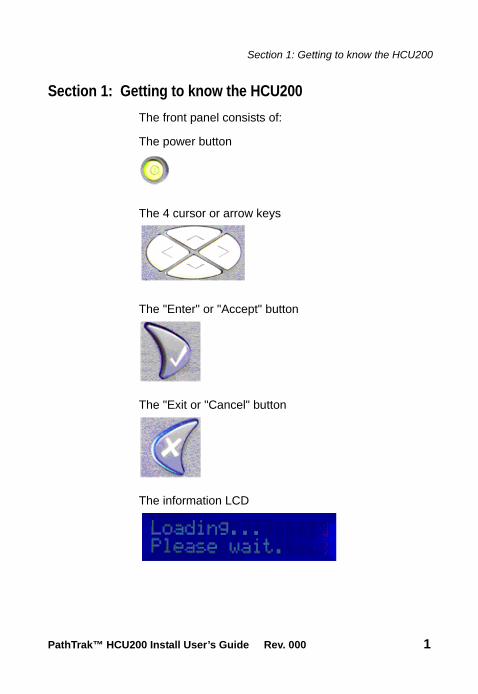
The front panel consists of:
The power button
The 4 cursor or arrow keys
The "Enter" or "Accept" button
The "Exit or "Cancel" button
The information LCD
PathTrak™ HCU200 Install User’s Guide Rev. 000 1

Section 2: HCU200 Unpacking and Setup
Section 2: HCU200 Unpacking and Setup
1 Remove HCU200 from box and carefully remove all packaging material.
2 Mount HCU200 module in rack using the four holes provided on the front panel.
3 Connect grounding strap of chassis to Earth Grounding termination screws on the rear panel of the HCU200.
4 Remove the protective cover over the DC power lugs on the rear panel of the HCU200.
a If using an existing -48VDC power supply double-check that power is turned off. Connect the -48V and RTN leads from the power supply to the appropriate power lugs on the rear panel of the HCU200.
b If using the JDSU-supplied optional AC power adaptor, connect the adaptor terminals to the appropriate HCU200 power lugs. Black wire goes to -48VDC lug, white wire goes to RTN lug.
5 Replace the clear plastic cover over the power lugs.
6 Connect jumpers from the RF source (commonly 8-way splitter off of return optical receiver) to the appropriate ports on the rear of the HCU200.
7 If using an HSM-1000 for Field View capability please see Document 6710-30-0005 (HSM-1000 Install Guide) for details of HSM installation and configuration.
8 Connect Ethernet feed to RJ45 connector socket on the rear of the HCU200.
9 Apply power to the HCU200. Once power is applied to the HCU200 the LCD will display:
2 PathTrak™ HCU200 Install User’s Guide Rev. 000
Section 2: HCU200 Unpacking and Setup
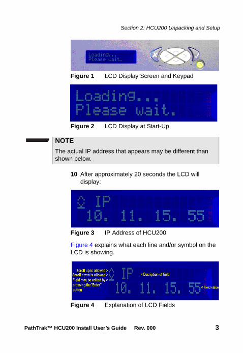
Figure 1 LCD Display Screen and Keypad
Figure 2 LCD Display at Start-Up
10 After approximately 20 seconds the LCD will display:
Figure 3 IP Address of HCU200
Figure 4 explains what each line and/or symbol on the LCD is showing.
Figure 4 Explanation of LCD Fields
NOTE
The actual IP address that appears may be different than shown below.
PathTrak™ HCU200 Install User’s Guide Rev. 000 3
Section 2: HCU200 Unpacking and Setup
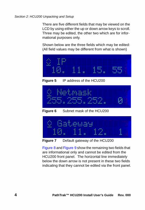
There are five different fields that may be viewed on the LCD by using either the up or down arrow keys to scroll. Three may be edited, the other two which are for infor-mational purposes only.
Shown below are the three fields which may be edited: (All field values may be different from what is shown)
Figure 5 IP address of the HCU200
Figure 6 Subnet mask of the HCU200
Figure 7 Default gateway of the HCU200
Figure 8 and Figure 9 show the remaining two fields that are informational only and cannot be edited from the HCU200 front panel. The horizontal line immediately below the down arrow is not present in these two fields indicating that they cannot be edited via the front panel.
4 PathTrak™ HCU200 Install User’s Guide Rev. 000

Section 2: HCU200 Unpacking and Setup
Figure 8 Physical (MAC) address of the HCU200 Ethernet adapter
Figure 9 IP address of the PathTrak server that this HCU200 is connected to (This will change/update when the HCU200 is added to a new server)
11 Using the keypad and display on front panel or PathTrak Client software, IP address of HCU200 to appropriate value. Setting the IP address informa-tion on the HCU200 is a simple process done completely from the front panel of the unit.
12 To set the IP address of the HCU200, use the up or down arrow keys to scroll to the IP address field on the LCD and press the "Enter" button. The hori-zontal line that indicates that this is a field that may be edited drops to the bottom of the first digit in the IP address field becoming a cursor and indicating that the HCU is now in "edit mode" (Figure 10).
CAUTION
Before setting any IP address information in the HCU200, please confirm with your network administrator that the IP addresses you have are valid for your network configuration and will not cause any conflicts on your local area network.
PathTrak™ HCU200 Install User’s Guide Rev. 000 5
Section 2: HCU200 Unpacking and Setup
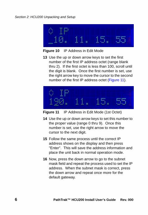
Figure 10 IP Address in Edit Mode
13 Use the up or down arrow keys to set the first number of the first IP address octet (range blank thru 2). If the first octet is less than 100, scroll until the digit is blank. Once the first number is set, use the right arrow key to move the cursor to the second number of the first IP address octet (Figure 11).
Figure 11 IP Address in Edit Mode (1st Octet)
14 Use the up or down arrow keys to set this number to the proper value (range 0 thru 9). Once this number is set, use the right arrow to move the cursor to the next digit.
15 Follow the same process until the correct IP address shows on the display and then press "Enter". This will save the address information and place the unit back in normal operation mode.
16 Now, press the down arrow to go to the subnet mask field and repeat the process used to set the IP address. When the subnet mask is correct, press the down arrow and repeat once more for the default gateway.
6 PathTrak™ HCU200 Install User’s Guide Rev. 000

Section 2: HCU200 Unpacking and Setup
17 There is no need to reboot the HCU200. Once you press the "Enter" button at the end of each field, the address is set and applied. When all the addresses are set, verify network connectivity from the Path-Trak server to the HCU200.
18 The PathTrak Server AND Client must be at least version 2.6 to recognize the HCU200.
19 Proceed with adding the HCU200 to a PathTrak Server per instructions documented in Chapter Three of document 6510-00-0430.
Figure 12 HCU200 Rear Panel
PathTrak™ HCU200 Install User’s Guide Rev. 000 7
Section 3: Related Information
Section 3: Related Information
Use this guide in conjunction with the following informa-tion:
– JDS Uniphase Corporation DSAM Product Family Series Server/Client Complete DSAM Meter Func-tionality Installation Guide (P/N 6510-30-0416)
– JDS Uniphase Corporation DSAM Product Family Series RPM1000 Installation Guide(P/N 6510-30-0415)
– JDS Uniphase Corporation DSAM Product Family Series RPM2000 Installation Guide(P/N 6510-30-0423)
– JDS Uniphase Corporation DSAM Product Family Series RPM3000 Quick Start Guide(P/N 21121380-001)
8 PathTrak™ HCU200 Install User’s Guide Rev. 000

Section 4: Technical Assistance
Section 4: Technical Assistance
If you need assistance or have questions related to the use of this product, call or e-mail JDS Uniphase Corpo-ration’s Technical Assistance Center for customer support.
Table 1 Technical assistance centers
Region Phone Number
CableTV/Multimedia Products
1 800 428 4424 Ext. 8350(America)1 317 788 9351 Ext. 8350(World Wide)
Europe, Africa, and Mid-East
+49 (0) 7121 86 1345(Europe)
+800 882 85822(European Freephone)
+49 (0) 6172 59 11 00(JDS Uniphase Corporation Germany)
+33 (0) 1 39 30 24 24 (JDS Uniphase Corporation France)
Asia Pacific +852 2892 0990(Hong Kong)
+86 10 6655 5988(Beijing-China)
All others 1 866 228 3762 [email protected]
PathTrak™ HCU200 Install User’s Guide Rev. 000 9

Section 4: Technical Assistance
During off-hours, you can request assistance by doing one of the following: leave a voice mail message at the Technical Assistance number in your region; e-mail North American Technical Assistance Center, [email protected], or European Technical Assistance Center, [email protected]; or submit your question using our online Technical Assistance Request form at www.jdsu.com.
10 PathTrak™ HCU200 Install User’s Guide Rev. 000
Section 5: Warnings
Section 5: Warnings
The HCU200 is a Measurement Category I device for measurements on circuits and SHOULD NOT be used for measurements within measurement categories II, III and IV circuits*.
* Measurement Category I: Such voltage measure-ments include signal levels, special equipment, limited-energy parts of equipment, circuits powered by regulated low-voltage sources, and electronics.
WARNING
If the equipment is used in a manner not specified by the manufacturer, the protection provided by the equipment may be impaired.
WARNING
Do not disassemble the HCU.
Do not attempt to service this product yourself. There are no user-serviceable parts inside. Contact the appropriate JDSU representative for HCU repair or calibration.
PathTrak™ HCU200 Install User’s Guide Rev. 000 11

Section 6: Equipment Ratings
Section 6: Equipment Ratings
Input Connection Description
– 16 RF Input Ports, 75 ohm,dynamic voltage range 0-50 dBmV
– 1 Serial RS232 port
– 1 10/100 baseT Ethernet port
– 1 USB port
– 1 Trigger I/O port
– 2 Earth Grounding Termination screws
Environmental Conditions
– Operating Temperature:5°C (41°F) to 45°C (113°F)
12 PathTrak™ HCU200 Install User’s Guide Rev. 000


Test and Measurement Regional Sales
North AmericaToll Free: 1 800 638 2049Tel: +1 240 404 2999Fax:+1 240 404 2195
Latin AmericaTel: 954-688-5660Fax:954-846-8856
Asia PacificTel: +852 2892 0990Fax:+852 2892 0770
EMEATel: +49 7121 86 2222Fax:+49 7121 86 1222
www.jdsu.com
Doc. 21155873-001 Rev. 000September- 2010English