JCM TRAINING OVERVIEW DBV-135 Phone # (800) 683-7248 (702) 651 0000 Technical Support # (800)...
17
JCM TRAINING OVERVIEW DBV-135 Phone # (800) 683-7248 (702) 651 0000 Technical Support # (800) 651-3444 Fax # (702) 651-0214 E-mail [email protected] Web Address http://www.jcm-american.co
-
Upload
alexandra-houston -
Category
Documents
-
view
235 -
download
0
description
Connect validator head to VM-401 and Check Pin Board Insure all dip-switches on validator head and VM-401 are set to the ON position. Preparing for Calibration
Transcript of JCM TRAINING OVERVIEW DBV-135 Phone # (800) 683-7248 (702) 651 0000 Technical Support # (800)...

JCM TRAINING OVERVIEWDBV-135
Phone # (800) 683-7248 (702) 651 0000Technical Support # (800) 651-3444
Fax # (702) 651-0214
E-mail [email protected]
Web Address http://www.jcm-american.com

CLEANING THE HEAD• Absolutely NO solvents should be used !!!• Absolutely NO cleaning cards.• Do not soak the unit• If service can determine that a solvent was used it will void the warranty, if
applicable• Mild soap and water on a clean soft cloth should be used.• Wipe the lenses, belts, rollers and bill path until clean.• If a lens is altered in any way it must be replaced (scratched, clouded etc)• Do not scratch the rollers because they will pick up dirt faster, increasing PM
scheduling.• If belts have a glaze on them or if you can see timing marks through them, or
if they have frayed edges they must be replaced.

Connect validator head to VM-401 and Check Pin BoardInsure all dip-switches on validator head and VM-401 are set to the ON position.
Preparing for Calibration
NO DISCRIPTION NO DISCRIPTIONP1 MAG Sensor P7 PT2P2 HPT1 Black P8 LEVER (PTI)P3 HPT2 Black P9 PT3P4 HPT1 White 5V Analog 5 VP5 HPT2 White GND Signal GroundP6 PT1

Calibration utilizing VM-401 & OscilloscopeSensor location Variable resistors
Name Function VR SensorPT1 Entrance transmission VR1 Mag head gainPT2 Bill transmission VR2 HPT1 black levelPT3 Entrance transmission VR3 HPT2 black level
HPT1 Reflective (surface) VR4 HPT1 white levelHPT2 Reflective ( reverse) VR5 HPT2 white levelMAG Magnetic Pattern VR6 PT1 LevelPTI Bill transit detector VR7 PT2 Level
VR8 PT3 Level
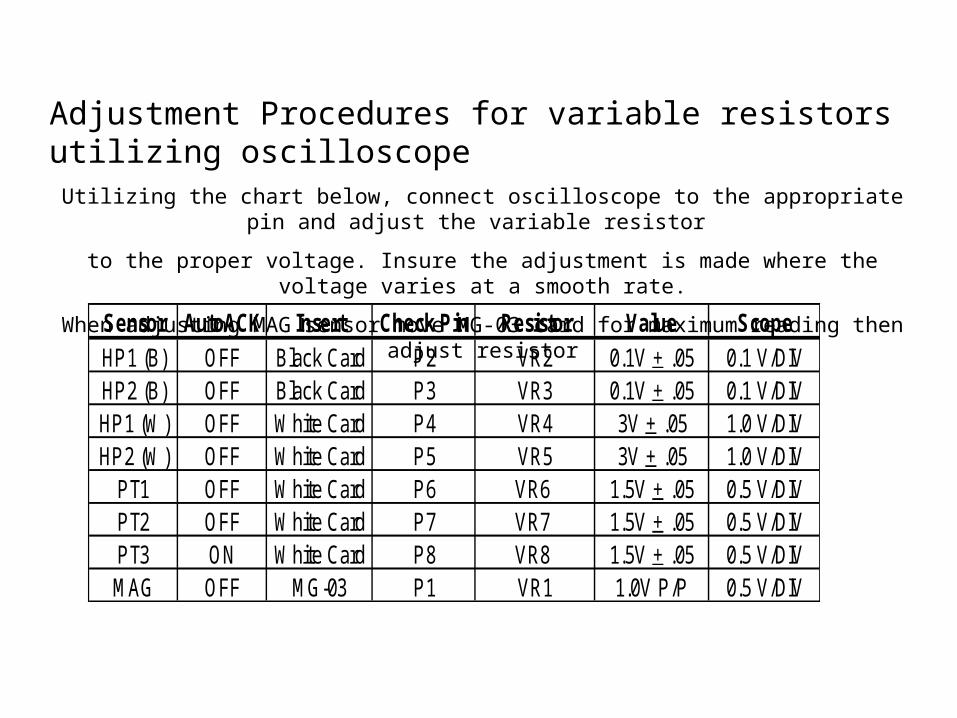
Adjustment Procedures for variable resistors utilizing oscilloscopeUtilizing the chart below, connect oscilloscope to the appropriate pin and adjust the variable resistor
to the proper voltage. Insure the adjustment is made where the voltage varies at a smooth rate.
When adjusting MAG sensor move MG-03 card for maximum reading then adjust resistor
Sensor AutoACK Insert Check Pin Resistor Value ScopeHP1 (B) OFF Black Card P2 VR2 0.1V + .05 0.1 V/DIVHP2 (B) OFF Black Card P3 VR3 0.1V + .05 0.1 V/DIVHP1 (W) OFF White Card P4 VR4 3V + .05 1.0 V/DIVHP2 (W) OFF White Card P5 VR5 3V + .05 1.0 V/DIV
PT1 OFF White Card P6 VR6 1.5V + .05 0.5 V/DIVPT2 OFF White Card P7 VR7 1.5V + .05 0.5 V/DIVPT3 ON White Card P8 VR8 1.5V + .05 0.5 V/DIVMAG OFF MG-03 P1 VR1 1.0V P/P 0.5 V/DIV

FUNCTIONAL TESTING
No. S-RES REJ ACK CONTENTS1 Test for head forward motor rotation test.2 Test for head reverse motor rotation test3 Validator sensor test4 Stacker performance test5 Unit complete cycle test6 Solenoid lever and sensor test7 Stacker sensor test8 Bill acceptance test
Quick reference for VM-401 tester

TEST # 1no 01
BSY VEND1 VEND2 VEND3
ABN STKF Be sure that “no 01” is in display andset the E/D switch to enable then followlegend on left.By setting E/D to disableallows tester to be given another test command.
E/D
no 01
BSY VEND1 VEND2 VEND3
ABN STKF
E/D
no 01
BSY VEND1 VEND2 VEND3
ABN STKF
E/D
Carrier speed is fast
Carrier speed is appropriate
Carrier speed is slow
N/G
N/G
OK
S-RESET REJ ACK
S-RESET REJ ACK
S-RESET REJ ACK
TEST # 2Press down the REJ buttonBe sure that “no 02” is in display andset the E/D switch to enable then followlegend on left. NOTE by setting E/D to disable allows tester to be given another test command.
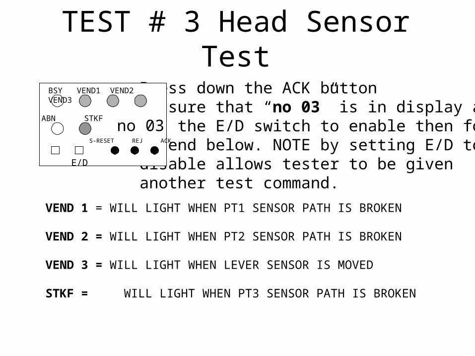
TEST # 3 Head Sensor TestPress down the ACK buttonBe sure that “no 03” is in display andset the E/D switch to enable then followlegend below. NOTE by setting E/D to disable allows tester to be given another test command.
VEND 1 = WILL LIGHT WHEN PT1 SENSOR PATH IS BROKEN
VEND 2 = WILL LIGHT WHEN PT2 SENSOR PATH IS BROKEN
VEND 3 = WILL LIGHT WHEN LEVER SENSOR IS MOVED
STKF = WILL LIGHT WHEN PT3 SENSOR PATH IS BROKEN
E/D no 03
BSY VEND1 VEND2 VEND3
ABN STKF
E/D
S-RESET REJ ACK
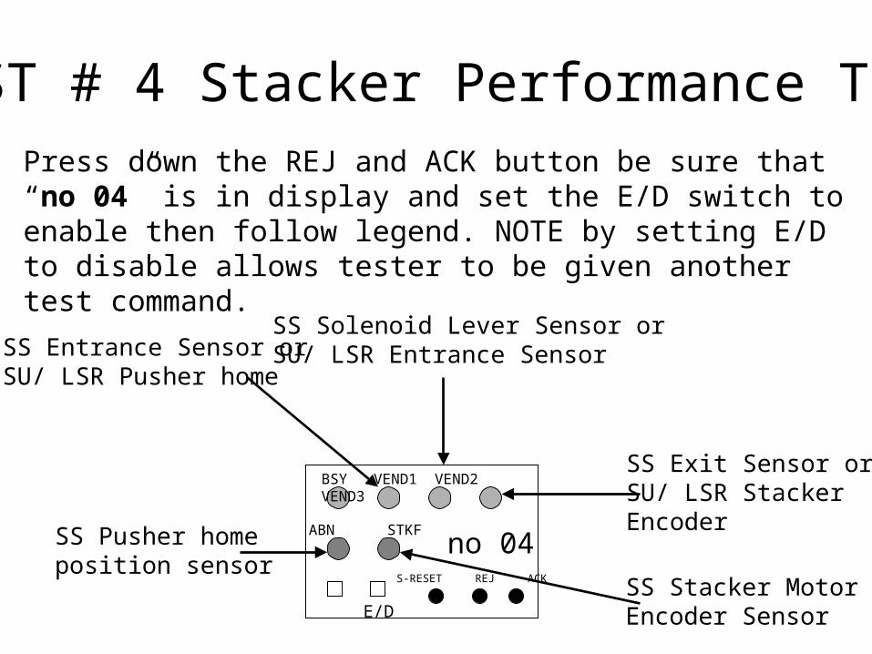
TEST # 4 Stacker Performance TestPress down the REJ and ACK button be sure that “no 04” is in display and set the E/D switch to enable then follow legend. NOTE by setting E/D to disable allows tester to be given another test command.
E/D no 04
BSY VEND1 VEND2 VEND3
ABN STKF
E/D
SS Exit Sensor orSU/ LSR Stacker Encoder
SS Solenoid Lever Sensor orSU/ LSR Entrance SensorSS Entrance Sensor or
SU/ LSR Pusher home
SS Pusher home position sensor
SS Stacker MotorEncoder Sensor
S-RESET REJ ACK

TEST # 5 Carrying & Storage Test
Error CodeVEND 1 VEND 3VEND 2 Type of Abnormality
(1) Abnormality in the stacker motor.
(2) Abnormality in the encoder sensor.
(1) Abnormality in the validator sensor.(2) A bill remains inside validator.(1) Abnormality in the stacker sensor.(2) A bill remains inside stacker path.
Cash box is full.
Abnormality in the stacker solenoid.
(1) Abnormality in the pushing unit.(2) Abnormality in the stacker encoder.
Press down the S-RESET button Be sure that “no 05” is in display andset the E/D switch to enable, if an error occurs follow legend below. NOTE by setting E/D to disable allows tester to be given another testcommand.
E/D no 05
BSY VEND1 VEND2 VEND3
ABN STKF
E/D
S-RESET REJ ACK

TEST # 6 Stacker Solenoid TestPress down the REJ & S-RESET button Be sure that “no 06” is in the display and set the E/D switch to enable, if an error occurs follow legend below. NOTE by setting E/D to disable allows tester to be given another test command. NOTE this test DOES NOT apply to horizontal style transports (Bally, Sigma, Williams ect.)
E/D no 04
BSY VEND1 VEND2 VEND3
ABN STKF
E/D
Exit Sensor
Solenoid Lever SensorEntrance Sensor
Pusher Home SensorStacker MotorEncoder Sensor
S-RESET REJ ACK

TEST # 7 Stacker Sensor Test
E/D no 04
BSY VEND1 VEND2 VEND3
ABN STKF
E/D
SS Exit Sensor orSU/ LSR Stacker Encoder
SS Solenoid Lever Sensor orSU/ LSR Entrance SensorSS Entrance Sensor or
SU/ LSR Pusher home
SS Pusher home position sensor
SS Stacker MotorEncoder Sensor
Press down the ACK & S-RESET button Be sure that “no 07” is in the display and set the E/D switch to enable, if an error occurs follow legend below. NOTE by setting E/D to disable allows tester to be given another test command.
S-RESET REJ ACK

Stacker Sensor Locations
(1) Feed in sensor (photo transistor)(2) Stacker lever sensor(3) Feed out sensor (phototransistor)(4) Stacker encoder sensor (5) Feed out sensor (LED)
(6) Feed in sensor (LED)

SU/ LSR STYLE SENSORS

TEST # 8 Bill Acceptance Test
VEND 1 VEND 2 VEND 3 Type of bill
$1$5
$10$20$50$100
This test can be done with or with out a stacker. With head alone you go into test # 8 with out changing dip switch settings. With a stacker you must turn dip switch 2-1 on before enabling test # 8.The validator identifies the type of bill, When a bill is returned the reason is indicated by the numberof times the ABN led blinks also the return code is in the display (Refer to the table of returncodes )If you did not have a chance to feed in a bill and the validator went in to an abnormality error the ABN will blink then pause repeatedly the number of blinks is the code ( Refer to abnormal error codes ) NOTE this error will not be seen in the display.
Press down the REJ, ACK and S-RESET button be sure that “no 08” is in display and set the E/D switch to enable then follow legend below.
E/D no 08
BSY VEND1 VEND2 VEND3
ABN STKF
E/D
S-RESET REJ ACK
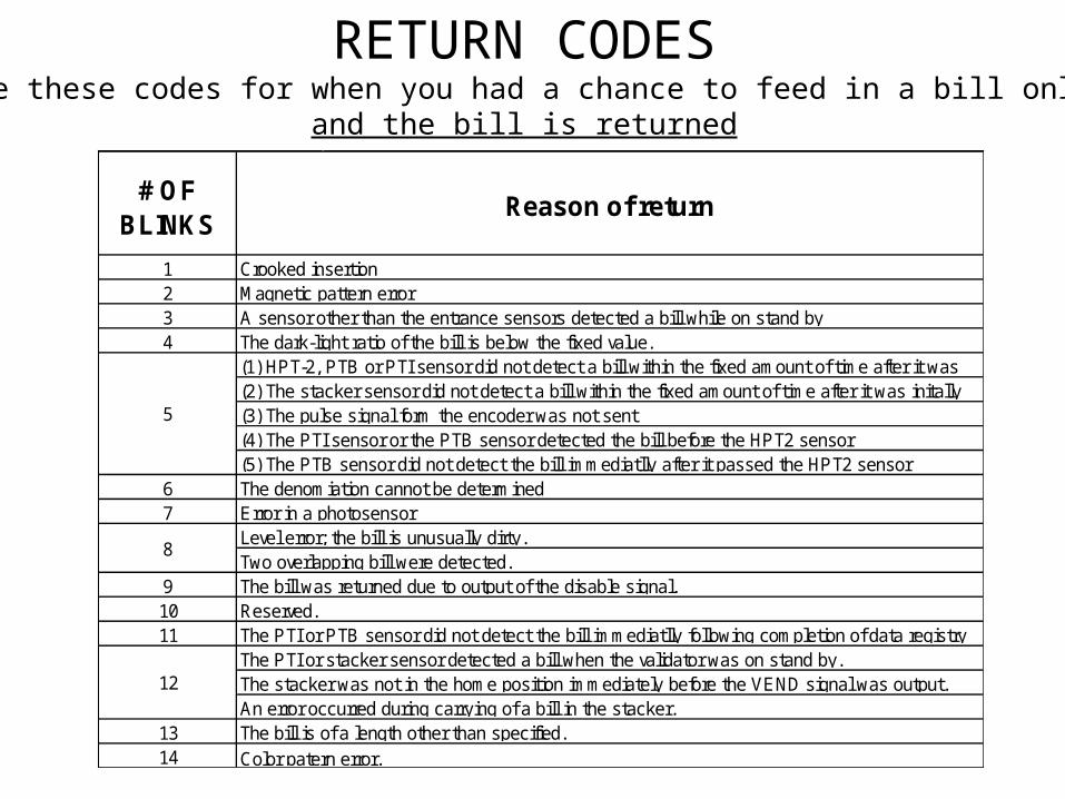
RETURN CODESUse these codes for when you had a chance to feed in a bill only
and the bill is returned
# OF BLINKS
1234
67
91011
1314
Reason of return
Crooked insertionMagnetic pattern errorA sensor other than the entrance sensors detected a bill while on stand byThe dark-light ratio of the bill is below the fixed value.
5
(1) HPT-2, PTB or PTI sensor did not detect a bill within the fixed amount of time after it was (2) The stacker sensor did not detect a bill within the fixed amount of time after it was initally (3) The pulse signal form the encoder was not sent(4) The PTI sensor or the PTB sensor detected the bill before the HPT2 sensor(5) The PTB sensor did not detect the bill immediatlly after it passed the HPT2 sensorThe denomiation cannot be determinedError in a photosensor
8 Level error; the bill is unusually dirty. Two overlapping bill were detected.
12The PTI or stacker sensor detected a bill when the validator was on stand by.The stacker was not in the home position immediately before the VEND signal was output.An error occurred during carrying of a bill in the stacker.The bill is of a length other than specified.Color patern error.
The bill was returned due to output of the disable signal.Reserved.The PTI or PTB sensor did not detect the bill immediatlly following completion of data registry
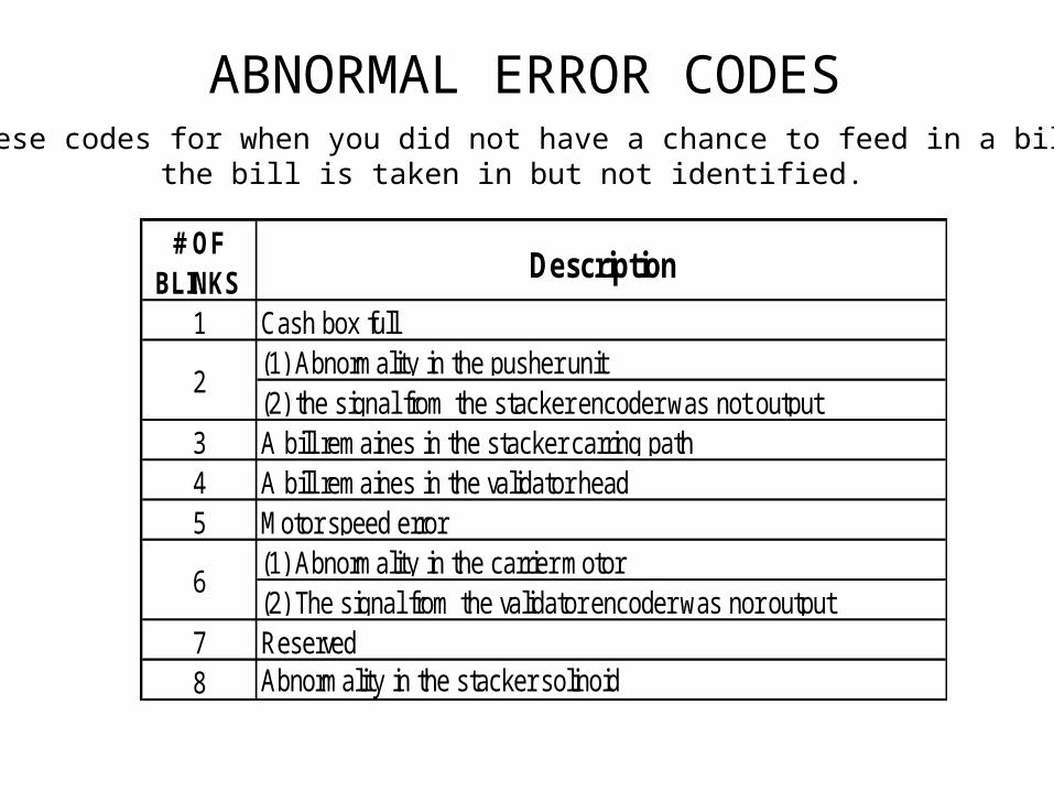
ABNORMAL ERROR CODESUse these codes for when you did not have a chance to feed in a bill or
the bill is taken in but not identified.
# OF BLINKS Description
1 Cash box full(1) Abnormality in the pusher unit(2) the signal from the stacker encoder was not output
3 A bill remaines in the stacker carring path4 A bill remaines in the validator head5 Motor speed error
(1) Abnormality in the carrier motor(2) The signal from the validator encoder was nor output
7 Reserved8 Abnormality in the stacker solinoid
2
6