JB4 – 135/335/535 E Series Installation Guide – …shop.ez-p.de/media/pdf/JB4PnP.pdfRemove the...
31
JB4 – 135/335/535 E Series Installation Guide – 6/28/2015 JB4 Installation Guide © 2009 Copyright Burger Motor Sports, LLC 1 / 31 Use subject to terms and conditions posted at http://www.burgertuning.com/terms THIS PART IS LEGAL FOR USE ONLY IN COMPETITION RACING VEHICLES AS DEFINED UNDER CALIFORNIA LAW, AND IS NOT LEGAL FOR USE IN ANY OTHER MOTOR VEHICLE. California law defines a "racing vehicle" as "a competition vehicle not used on public highways." (Calif. Health & Safety Code 39048) This part may only be used on competition racing vehicles operated exclusively on a closed course in conjunction with a sanctioned racing event. Competition-only motor vehicles may not be driven to a racing event on a public highway and must be transported on a trailer or other carrier. USE OF THIS PART IN ANY OTHER VEHICLE MAY SUBJECT YOU TO FINES AND PENALTIES FOR VIOLATION OF FEDERAL AND/OR STATE LAW, WILL VOID YOUR WARRANTY FROM BURGER MOTORSPORTS, INC, AND CAN VOID YOUR VEHICLE'S WARRANTY. It is your responsibility to comply with all applicable federal and state laws relating to use of this part, and Burger Motorsports, Inc hereby disclaims any liability resulting from the failure to use this part in compliance with all applicable federal and state laws.
Transcript of JB4 – 135/335/535 E Series Installation Guide – …shop.ez-p.de/media/pdf/JB4PnP.pdfRemove the...

JB4 – 135/335/535 E Series Installation Guide – 6/28/2015
JB4 Installation Guide
© 2009 Copyright Burger Motor Sports, LLC
1 / 31
Use subject to terms and conditions posted at http://www.burgertuning.com/terms
THIS PART IS LEGAL FOR USE ONLY IN COMPETITION RACING VEHICLES AS DEFINED UNDER
CALIFORNIA LAW, AND IS NOT LEGAL FOR USE IN ANY OTHER MOTOR VEHICLE. California law
defines a "racing vehicle" as "a competition vehicle not used on public highways." (Calif. Health & Safety Code
39048) This part may only be used on competition racing vehicles operated exclusively on a closed course in
conjunction with a sanctioned racing event. Competition-only motor vehicles may not be driven to a racing event
on a public highway and must be transported on a trailer or other carrier. USE OF THIS PART IN ANY OTHER
VEHICLE MAY SUBJECT YOU TO FINES AND PENALTIES FOR VIOLATION OF FEDERAL AND/OR
STATE LAW, WILL VOID YOUR WARRANTY FROM BURGER MOTORSPORTS, INC, AND CAN VOID
YOUR VEHICLE'S WARRANTY. It is your responsibility to comply with all applicable federal and state laws
relating to use of this part, and Burger Motorsports, Inc hereby disclaims any liability resulting from the failure to
use this part in compliance with all applicable federal and state laws.

JB4 – 135/335/535 E Series Installation Guide – 6/28/2015
JB4 Installation Guide
© 2009 Copyright Burger Motor Sports, LLC
2 / 31
NOTE BY DESIGN THE JB4 CONTROL BOARD SITS LOOSE WITHIN THE ENCLOSURE TO FACILITATE
COOLING. THE BOX MAY RATTLE IF YOU SHAKE IT HARD ENOUGH WHEN NOT INSTALLED. IT WILL NOT
RATTLE WITHIN THE DME COMPARTMENT ONCE INSTALLED.
Lock and close doors and trunk, and wait 10 minutes for the ECU to go to sleep. If you have comfort access place keys
inside the house to avoid waking up ECU. Alternatively you may disconnect the negative battery terminal. Do not open the
doors or unlock the car while the ECU connectors or JB4 control box are unplugged.
Access the ECU area and remove the ECU connectors – 135i/335i. If you have a 535i please skip to step 3b.
Reference Picture:
JB4 – 135/335/535 E Series Installation Guide – 6/28/2015
JB4 Installation Guide
© 2009 Copyright Burger Motor Sports, LLC
3 / 31
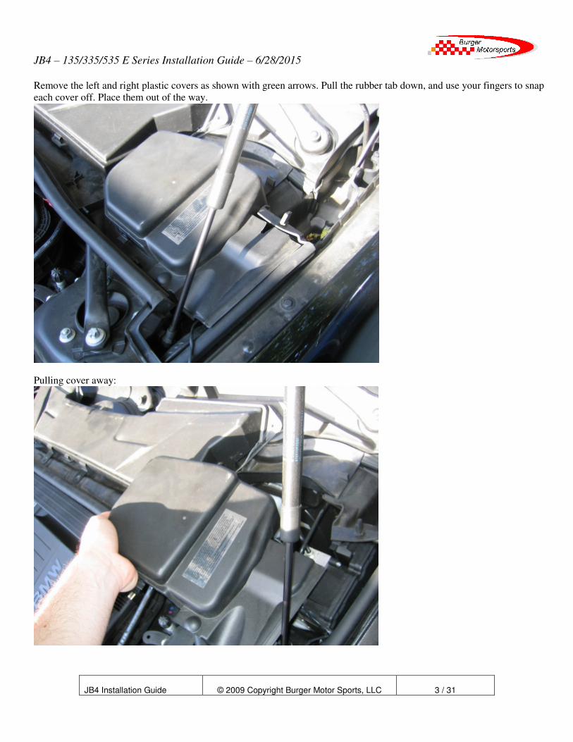
Remove the left and right plastic covers as shown with green arrows. Pull the rubber tab down, and use your fingers to snap
each cover off. Place them out of the way.
Pulling cover away:

JB4 – 135/335/535 E Series Installation Guide – 6/28/2015
JB4 Installation Guide
© 2009 Copyright Burger Motor Sports, LLC
4 / 31
Remove the left and right connectors/sensors as shown in purple. The passenger side sensor removes by pushing
in a small clip and rotating, while the optional driver side will lift off it present. Pull the tabs holding the wires out
by grasping the tabs and pulling towards you. The sensors will stay connected to the wires, just lay the sensors
and wires towards the front of the engine out of the way.
Optional driver side sensor:
Passenger side sensor:

JB4 – 135/335/535 E Series Installation Guide – 6/28/2015
JB4 Installation Guide
© 2009 Copyright Burger Motor Sports, LLC
5 / 31
Remove the six 8mm bolts holding down the HVAC air filter (shown in orange) and pull off the filter. Place it on the
ground out of the way.
Remove the two 8mm machine bolts shown in blue. These hold down the plastic cowl that we will be removing. There are
two rubber tabs on the left and right of the cowl that must be pulled out, as well as a wash fluid line on the left side.
Using a flat head screwdriver, push down the clips and pull forward the plastic rail holding the battery cable as shown. This
will remain in the car when the cowl is removed.

JB4 – 135/335/535 E Series Installation Guide – 6/28/2015
JB4 Installation Guide
© 2009 Copyright Burger Motor Sports, LLC
6 / 31
Next use the flat head screwdriver to release the cable bundle running right behind the power strip you just removed. Pull
the cable forward while lifting up the cowl to release it. The cowl should now lift out of the engine bay. Place it on the
ground out of the way.
Once the cowl is removed your engine bay should look like this:

JB4 – 135/335/535 E Series Installation Guide – 6/28/2015
JB4 Installation Guide
© 2009 Copyright Burger Motor Sports, LLC
7 / 31
Finally remove the left yellow plastic cover to expose the ECU. It is held down by two sliding clips on the sides, and small
plastic clips on the front and back.
JB4 – 135/335/535 E Series Installation Guide – 6/28/2015
JB4 Installation Guide
© 2009 Copyright Burger Motor Sports, LLC
8 / 31
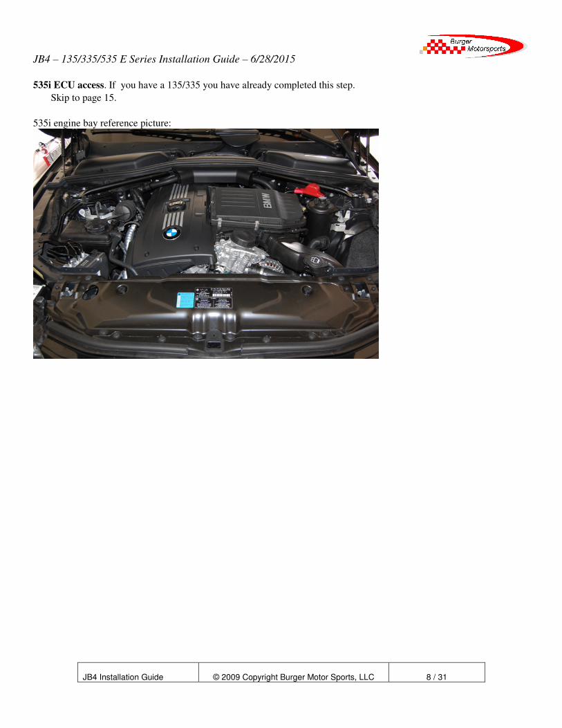
535i ECU access. If you have a 135/335 you have already completed this step.
Skip to page 15.
535i engine bay reference picture:

JB4 – 135/335/535 E Series Installation Guide – 6/28/2015
JB4 Installation Guide
© 2009 Copyright Burger Motor Sports, LLC
9 / 31
Disconnect the two sensors located by the hvac filter as shown.
Use a 12mm socket unlock the plastic bolt by gently turning it 1/4 turn, and then release the metal latch holding it down.

JB4 – 135/335/535 E Series Installation Guide – 6/28/2015
JB4 Installation Guide
© 2009 Copyright Burger Motor Sports, LLC
10 / 31
The filter should lift up and out as shown.
Pull off the weather stripping by pulling straight up and away until it has cleared the left tray, or about half way across the
engine.

JB4 – 135/335/535 E Series Installation Guide – 6/28/2015
JB4 Installation Guide
© 2009 Copyright Burger Motor Sports, LLC
11 / 31
Remove the slider as shown by lifting the clip and sliding towards the driver side.
Release the left side tray by rotating the 4 plastic retaining bolts 1/4 turn.

JB4 – 135/335/535 E Series Installation Guide – 6/28/2015
JB4 Installation Guide
© 2009 Copyright Burger Motor Sports, LLC
12 / 31
Lift away the rubber guard as shown.
Remove the t25 torx screw holding the tray to the shock tower.

JB4 – 135/335/535 E Series Installation Guide – 6/28/2015
JB4 Installation Guide
© 2009 Copyright Burger Motor Sports, LLC
13 / 31
Finally slide the tray towards the fender, up, and out.
Use an allen wrench to remove the 5 screws holding down the ECU cover.
JB4 – 135/335/535 E Series Installation Guide – 6/28/2015
JB4 Installation Guide
© 2009 Copyright Burger Motor Sports, LLC
14 / 31
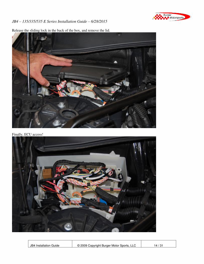
Release the sliding lock in the back of the box, and remove the lid.
Finally, ECU access!

JB4 – 135/335/535 E Series Installation Guide – 6/28/2015
JB4 Installation Guide
© 2009 Copyright Burger Motor Sports, LLC
15 / 31
Remove both the large and small ECU connectors and slide out all 4 subconnectors. Large black and small white are from the
larger left connector, small grey and small black are from the smaller right connector. The slider must be removed from the
small ECU connector to get the subconnectors out. It is generally easier to pull the large harness grommets off of the ends of the
yellow ECU box to make room to work. It may take some force to pull the sliders out.
Removing the slider from the smaller driver side subconnector.
JB4 – 135/335/535 E Series Installation Guide – 6/28/2015
JB4 Installation Guide
© 2009 Copyright Burger Motor Sports, LLC
16 / 31
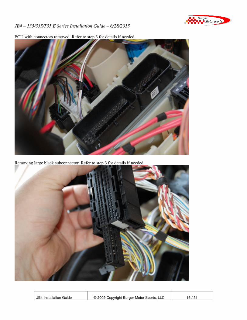
ECU with connectors removed. Refer to step 3 for details if needed.
Removing large black subconnector. Refer to step 3 for details if needed.
JB4 – 135/335/535 E Series Installation Guide – 6/28/2015
JB4 Installation Guide
© 2009 Copyright Burger Motor Sports, LLC
17 / 31
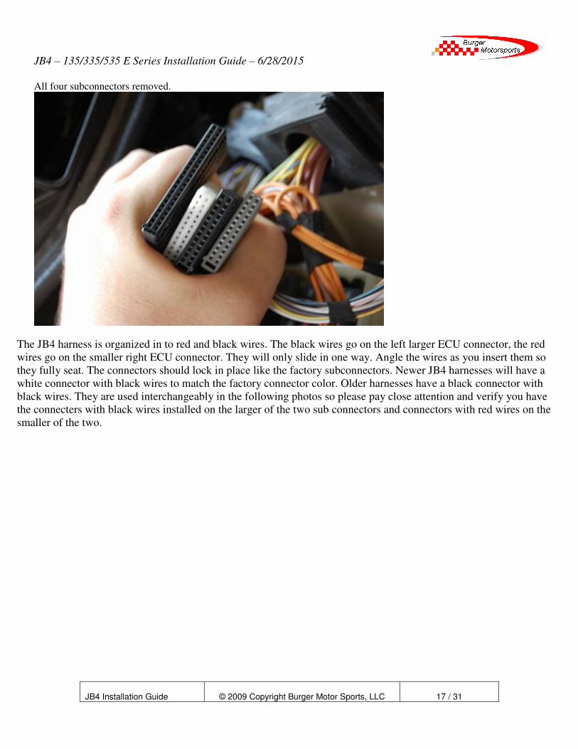
All four subconnectors removed.
The JB4 harness is organized in to red and black wires. The black wires go on the left larger ECU connector, the red
wires go on the smaller right ECU connector. They will only slide in one way. Angle the wires as you insert them so
they fully seat. The connectors should lock in place like the factory subconnectors. Newer JB4 harnesses will have a
white connector with black wires to match the factory connector color. Older harnesses have a black connector with
black wires. They are used interchangeably in the following photos so please pay close attention and verify you have
the connecters with black wires installed on the larger of the two sub connectors and connectors with red wires on the
smaller of the two.
JB4 – 135/335/535 E Series Installation Guide – 6/28/2015
JB4 Installation Guide
© 2009 Copyright Burger Motor Sports, LLC
18 / 31
.
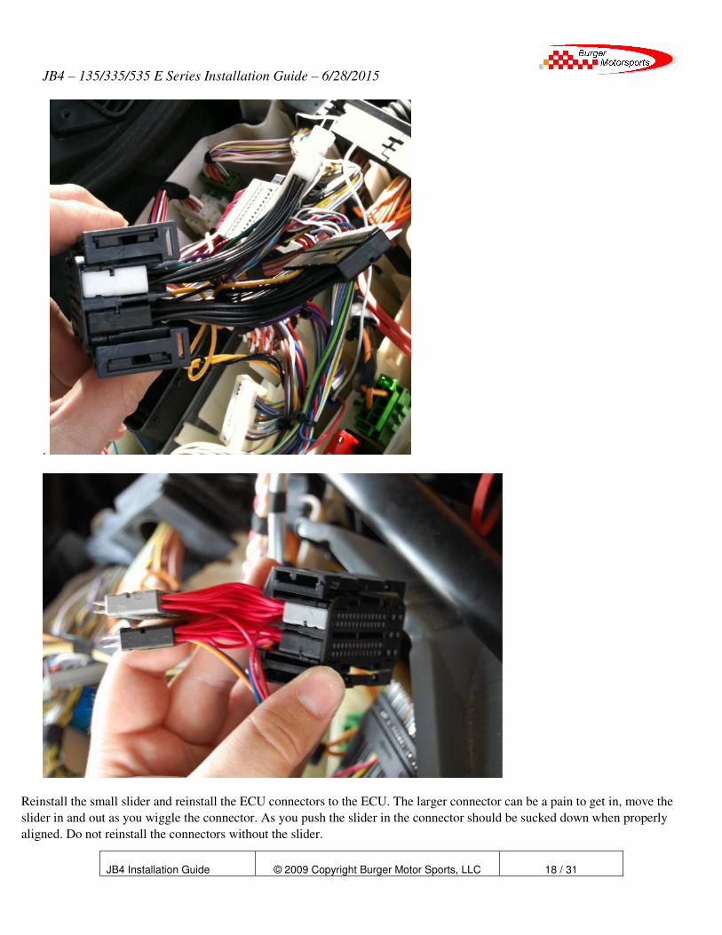
Reinstall the small slider and reinstall the ECU connectors to the ECU. The larger connector can be a pain to get in, move the
slider in and out as you wiggle the connector. As you push the slider in the connector should be sucked down when properly
aligned. Do not reinstall the connectors without the slider.

JB4 – 135/335/535 E Series Installation Guide – 6/28/2015
JB4 Installation Guide
© 2009 Copyright Burger Motor Sports, LLC
19 / 31
Plug in the original black 44 pin subconnector to the large black subconnector on the JB4 harness. You can plug the connector
in backwards so take care to ensure the horizontal slots / empty boxes at the front of each connector are to the right.
JB4 – 135/335/535 E Series Installation Guide – 6/28/2015
JB4 Installation Guide
© 2009 Copyright Burger Motor Sports, LLC
20 / 31
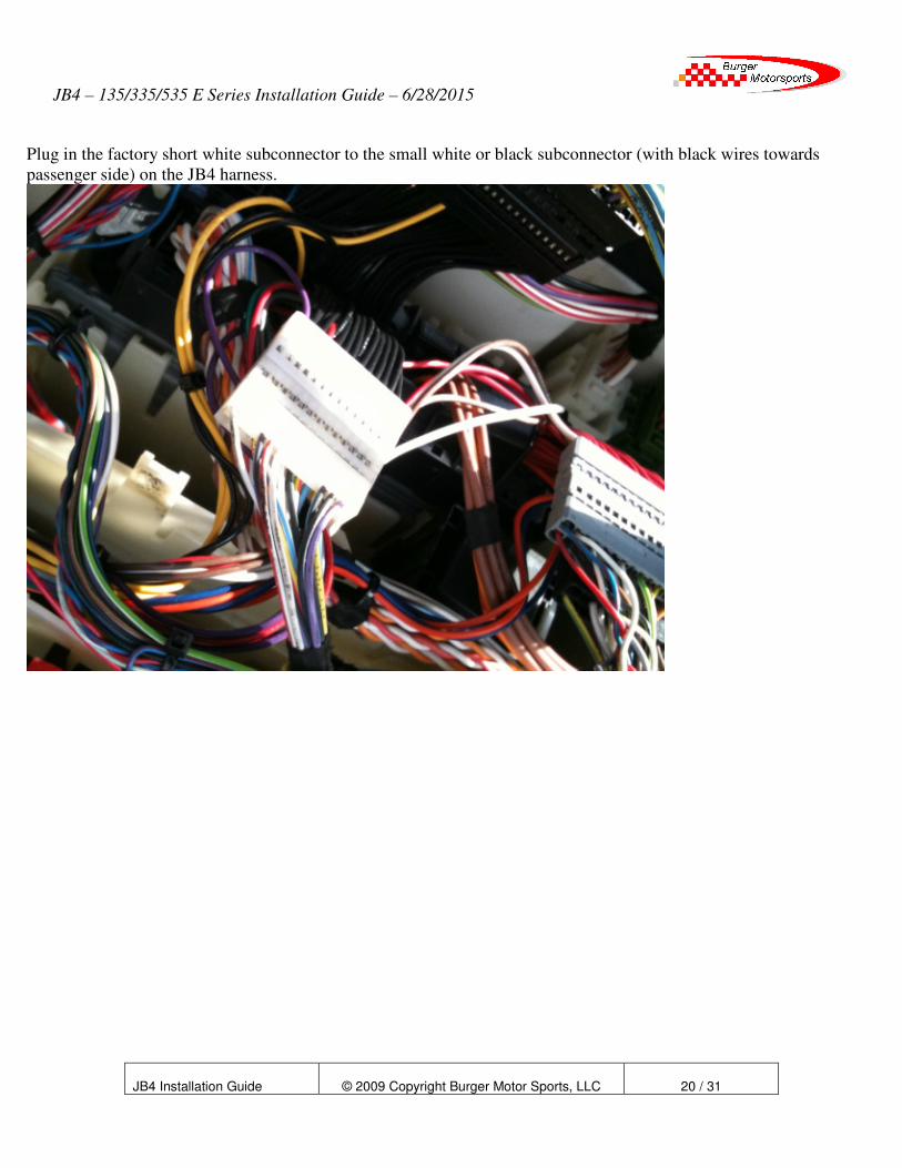
Plug in the factory short white subconnector to the small white or black subconnector (with black wires towards
passenger side) on the JB4 harness.

JB4 – 135/335/535 E Series Installation Guide – 6/28/2015
JB4 Installation Guide
© 2009 Copyright Burger Motor Sports, LLC
21 / 31
Plug in the factory short black subconnector to the small black subconnector (with red wires) on the JB4 harness. Verify boxes
line up.
Plug in the factory short grey subconnector to the small grey subconnector on the JB4 harness. Verify boxes line up.

JB4 – 135/335/535 E Series Installation Guide – 6/28/2015
JB4 Installation Guide
© 2009 Copyright Burger Motor Sports, LLC
22 / 31
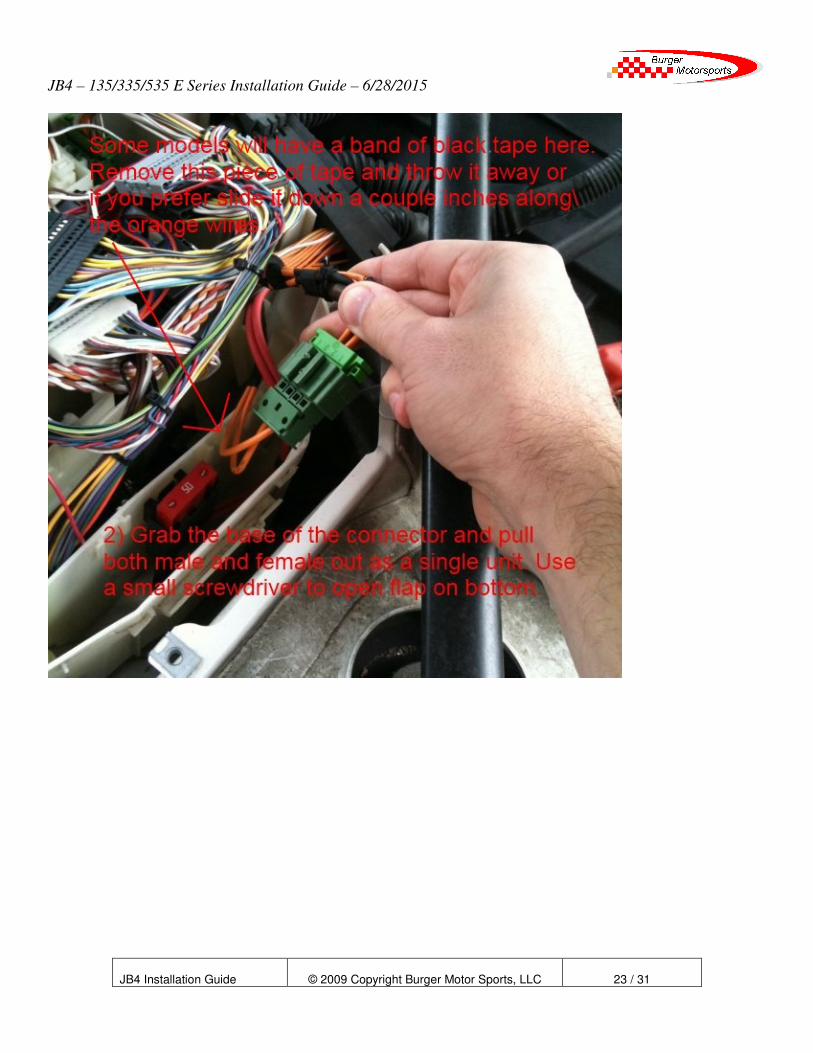
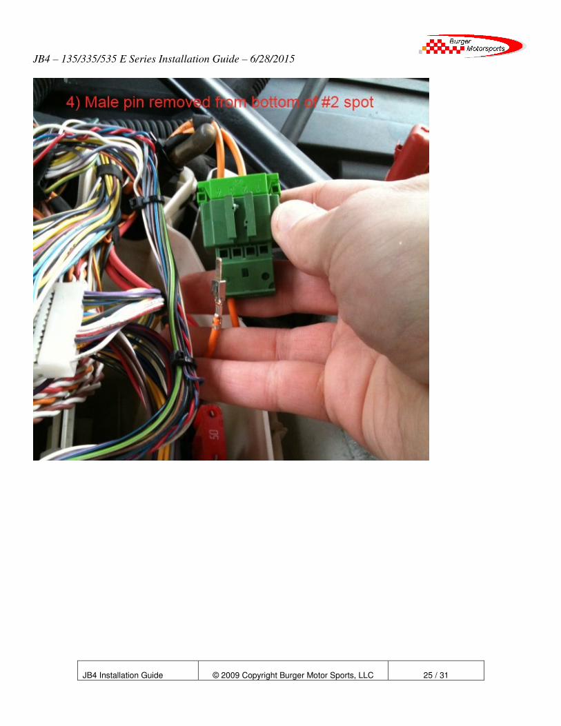
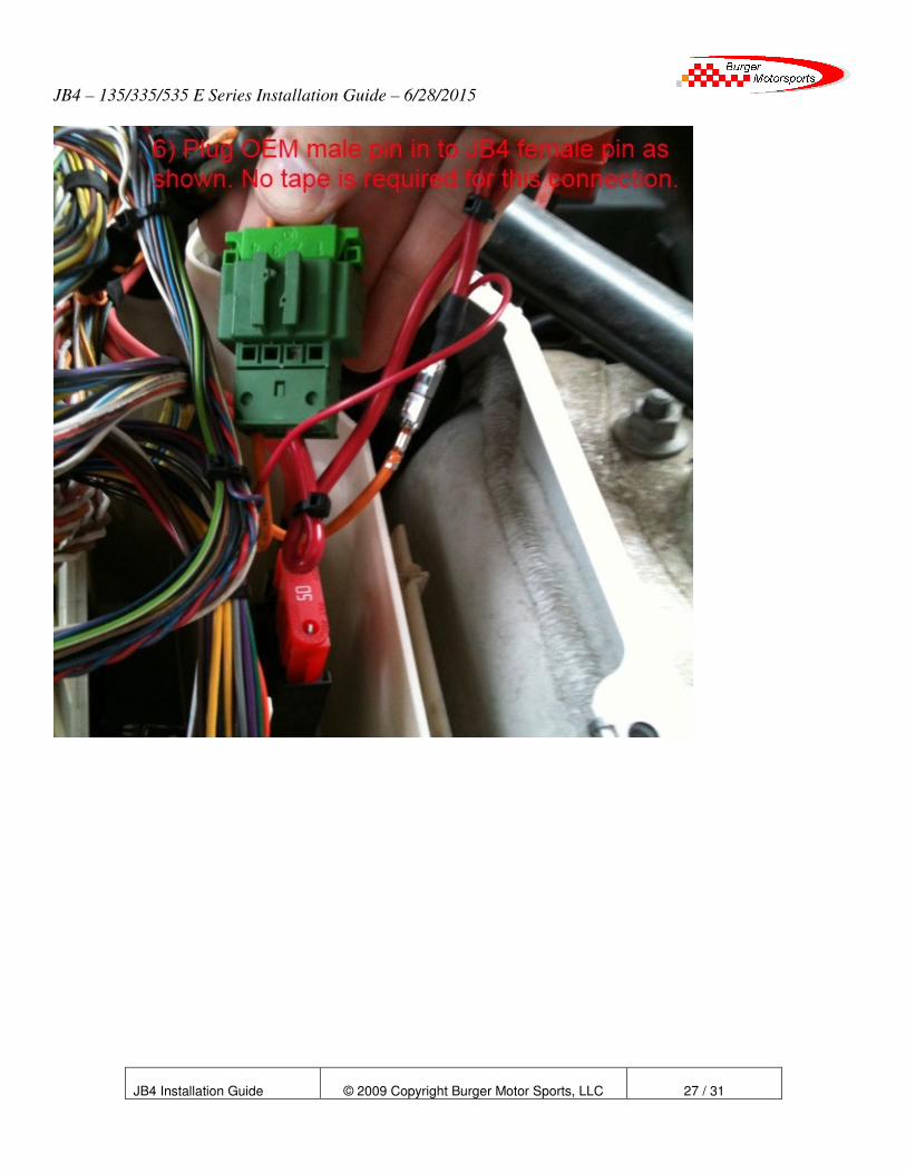
12) Install the JB4 power wire as shown in these photos:
JB4 – 135/335/535 E Series Installation Guide – 6/28/2015
JB4 Installation Guide
© 2009 Copyright Burger Motor Sports, LLC
23 / 31

JB4 – 135/335/535 E Series Installation Guide – 6/28/2015
JB4 Installation Guide
© 2009 Copyright Burger Motor Sports, LLC
24 / 31
JB4 – 135/335/535 E Series Installation Guide – 6/28/2015
JB4 Installation Guide
© 2009 Copyright Burger Motor Sports, LLC
25 / 31

JB4 – 135/335/535 E Series Installation Guide – 6/28/2015
JB4 Installation Guide
© 2009 Copyright Burger Motor Sports, LLC
26 / 31
JB4 – 135/335/535 E Series Installation Guide – 6/28/2015
JB4 Installation Guide
© 2009 Copyright Burger Motor Sports, LLC
27 / 31
JB4 – 135/335/535 E Series Installation Guide – 6/28/2015
JB4 Installation Guide
© 2009 Copyright Burger Motor Sports, LLC
28 / 31
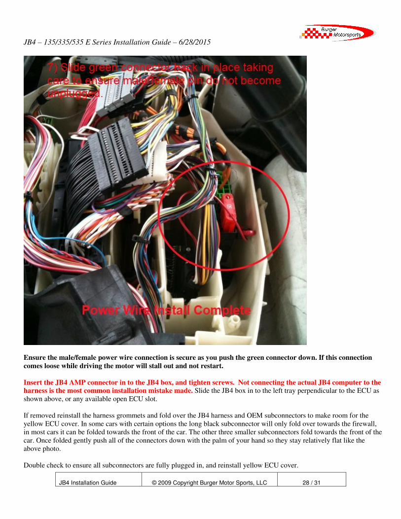
Ensure the male/female power wire connection is secure as you push the green connector down. If this connection
comes loose while driving the motor will stall out and not restart.
Insert the JB4 AMP connector in to the JB4 box, and tighten screws. Not connecting the actual JB4 computer to the harness is the most common installation mistake made. Slide the JB4 box in to the left tray perpendicular to the ECU as
shown above, or any available open ECU slot.
If removed reinstall the harness grommets and fold over the JB4 harness and OEM subconnectors to make room for the
yellow ECU cover. In some cars with certain options the long black subconnector will only fold over towards the firewall,
in most cars it can be folded towards the front of the car. The other three smaller subconnectors fold towards the front of the
car. Once folded gently push all of the connectors down with the palm of your hand so they stay relatively flat like the
above photo.
Double check to ensure all subconnectors are fully plugged in, and reinstall yellow ECU cover.

JB4 – 135/335/535 E Series Installation Guide – 6/28/2015
JB4 Installation Guide
© 2009 Copyright Burger Motor Sports, LLC
29 / 31
If you disconnected the battery reconnect the negative battery terminal. Upon first starting the car you will have a clock
warning (triangle with ! in the middle of it). All wheel drive (Xi) models may also have a DTS/DTC warning message,
which will turn itself off after a short drive. It is also not uncommon to have to set the clock 2 or 3 times before it saves.
Before reinstalling cowl and covers start the car. If it fails to start, takes a long time to start, shows a picture of a half yellow
engine in the dash (CEL), an orange service engine soon light (SES), or runs extremely rough, please refer to the
troubleshooting guide below. Please note it is normal on an unmodified car for the SES light to illuminate with the ignition
on before starting the motor. Only an SES light on with the motor running would be abnormal.
Optional BMS USB cable. If you elected to purchase the BMS USB cable for free firmware updates, new features, etc, as
we post them to N54Tech.com, connect it to the bottom of the JB4 control box. For cable routing you have two options.
Option 1 is to route it over the rubber grommet under the DME cover and leave it there for quick access. You'll just have to
lift up the one snap on black panel and can then route it in the window or door jamb to your laptop. Option 2 is to route it in
to the glove box. There is a DIY on n54tech.com.
Assuming all is well; reinstall the ECU cover, factory cowl, and related parts.
Congratulations, installation is complete! Keep in mind the JB4 includes cold/hot oil temperature protection so when oil
temperatures are below 160F degrees or over 270F degrees you will experience stock like performance.
By default map 1 is selected which is recommended for unmodified cars. Map 0 disables the unit all together. For the full
map and steering wheel control guide, FAQ, and latest firmware visit:
http://www.n54tech.com/forums/showthread.php?t=10605
If you have a 135i be sure to switch the steering wheel controls to 135i mode (menu 5 option 1) using guide in above link.
Remember to always use 91 octane (USA RM/2 standard) or higher grade fuel. The higher the octane, the more power you
will make. 93 octane will make more power than 91 octane, and 100 octane or a mix will make more power than straight 93
octane. Never use leaded or low lead fuel as it will damage your o2 sensors and/or catalytic converters. For extended load
use (e.g. road race course) mixing in higher octane fuel is suggested.
Use subject to terms and conditions posted at http://www.burgertuning.com/terms
JB4 – 135/335/535 E Series Installation Guide – 6/28/2015
JB4 Installation Guide
© 2009 Copyright Burger Motor Sports, LLC
30 / 31
How to read engine codes / reduced power mode / service engine soon light:
Any time you get check engine light (yellow half engine or reduced power indicator) or service engine soon light
(orange SES) the first step is to read the codes. With a JB4 installed there are two methods. The easiest method
for beginners is to connect the laptop interface and use the "read codes" button under settings. This will give a full
listing along with descriptions. Alternatively for more advanced users or if a laptop isn't available you may use
the in dash reading on menu 1 option 1. Directions for that method are here:
http://www.n54tech.com/forums/showpost.php?p=170898&postcount=1
If a JB4 is not installed you can also use a BT or CT tool to do the scan. Once you have the exact code details
email those in for advice.
Troubleshooting Guide
Troubleshooting is broken in to two distinct groups. The first are issues that come up during installation, like failure to start,
yellow engine light (CEL) upon first start, etc. The second are issues that arise after the tuner has been installed and working
properly for some time.
This guide deals only with installation related issues. But should you ever experience a yellow engine light (CEL) or service
engine soon code (SES), you should email BMS directly at [email protected] for technical advice. We have seen it
all and can quickly help you determine whether or not the issue is related to the JB4 and what to do next.
Common installation problems:
Engine cranks and cranks but will not start or takes a long time to start:
Cause 1) One or both ECU connectors are not fully seated. They can be tricky to get in but when done properly the
connector will seat itself as you are pushing the slider in. Remove connectors and try again until you are positive they are
fully seated.
Cause 2) One of the subconnectors is installed backwards, or is not lined up properly. Unplug all subconnectors and
carefully reinsert using install guide photos as reference.
Cause 3) You forgot to plug the JB4 box in to the harness.
Engine starts but has a big yellow check engine light showing (CEL):
Cause 1) One of the subconnectors is installed backwards, or is not lined up properly. Unplug all connectors and try again.
Cause 2) JB4 control box not plugged in.

JB4 – 135/335/535 E Series Installation Guide – 6/28/2015
JB4 Installation Guide
© 2009 Copyright Burger Motor Sports, LLC
31 / 31
Engine starts with no lights, but upon first drive a big yellow engine light (CEL) appears:
Cause 1) Normal ECU adaptation. It takes the ECU a few runs to fully adapt to the JB4 and in rare cases this can result in a
CEL. Especially if pushing the car hard after the tuner is first installed. Restart the car (the code will disappear) and continue
racing. If the code does not reappear then no further action is needed.
Cause 2) Map incompatibility. Although the JB4 is designed to work for all vehicles, some ECU versions, fuels, and
ambient conditions may require special mapping. Contact us for further instruction.
Engine starts but an orange "Service Engine Soon" (SES) light appears:
Cause 1) During the installation process you had some issue that you have since corrected, but the SES light is
still on. The JB4 includes code reading/deleting ability detailed in the command center document linked above.
Refer to this document on how to read and delete the SES code.


![Oedo Line Z / Jb4]b zcò€ m Exit - みんてつキッズ | 日本 ...kids.mintetsu.or.jp/concours/result/2015/image_uniq/2015...Oedo Line Z" / Jb4]b zcò€ m Exit Created Date 20160114200623Z](https://static.fdocuments.us/doc/165x107/5aae70db7f8b9aa8438c198a/oedo-line-z-jb4b-zc-m-exit-kids-line.jpg)