JAZZY 610 - Pride Mobility Products Corp.
43
Including Models: Jazzy 610 2S, Jazzy 610 2SP 1-800-800-8586 (US) 1-888-570-1113 (Canada) JAZZY 610 SERIES How a Power Chair should FEEL! ™
Transcript of JAZZY 610 - Pride Mobility Products Corp.

Including Models: Jazzy 610 2S, Jazzy 610 2SP
1-800-800-8586 (US) 1-888-570-1113 (Canada)
JAZZY 610S E R I E S
How a Power Chair should FEEL!™

2 www.pridemobility.com Jazzy 610 Series
S A F E T Y G U I D E L I N E S
Copyright © 2006Pride Mobility Products Corp.INFMANU2897/Rev D/December 2006
Authorized Pride Provider:_____________________________________________________________________
Address:________________________________________________________________________________
Phone Number:___________________________________________________________________________
Purchase Date:____________________________________________________________________________
NOTE: This owner’s manual is compiled from the latest specifications and product information availableat the time of publication. We reserve the right to make changes as they become necessary. Any changes toour products may cause slight variations between the illustrations and explanations in this manual and theproduct you have purchased.
The symbols below are used throughout this owner's manual and on the power chair to identify warnings and importantinformation. It is very important for you to read them and understand them completely.
WARNING! Indicates a potentially hazardous condition/situation. Failure to follow designatedprocedures can cause either personal injury, component damage, or malfunction. On the product,this icon is represented as a black symbol on a yellow triangle with a black border.
MANDATORY! These actions should be performed as specified. Failure to perform mandatoryactions can cause personal injury and/or equipment damage. On the product, this icon isrepresented as a white symbol on a blue dot with a white border.
PROHIBITED! These actions are prohibited. These actions should not be performed at any time orin any circumstances. Performing a prohibited action can cause personal injury and/or equipmentdamage. On the product, this icon is represented as a black symbol with a red circle and redslash.
Quick Reference Information
088 609 661

Jazzy 610 Series www.pridemobility.com 3
I. INTRODUCTION ..................................................................................................................................... 4
II. SAFETY ..................................................................................................................................................... 6
III. YOUR POWER CHAIR ........................................................................................................................ 16
IV. ASSEMBLY ............................................................................................................................................. 21
V. COMFORT ADJUSTMENTS ............................................................................................................ 23
VI. BATTERIES AND CHARGING ........................................................................................................ 30
VII. CARE AND MAINTENANCE ............................................................................................................ 34
VIII.WARRANTY ............................................................................................................................................ 40
C O N T E N T S

4 www.pridemobility.com Jazzy 610 Series
I . I N T R O D U C T I O N
SAFETYWELCOME to Pride Mobility Products Corporation (Pride). The power chair you have purchased combines state-of-the-art components with safety, comfort, and styling in mind. We are confident that these design features will provide youwith the conveniences you expect during your daily activities. Once you understand how to safely operate and care foryour power chair, it should give you years of trouble free operation and service.
Read and follow all instructions, warnings, and notes in this manual before attempting to operate your power chair for thefirst time. In addition, your safety depends upon you, as well as your provider, caretaker, or healthcare professional inusing good judgement.
If there is any information in this manual which you do not understand, or if you require additional assistance for setupor operation, please contact your authorized Pride Provider. Failure to follow the instructions in this manual andthose located on your power chair can lead to personal injury and/or damage to the power chair, includingvoiding the warranty.
PURCHASER’S AGREEMENTBy accepting delivery of this product, you promise that you will not change, alter, or modify this product or remove orrender inoperable or unsafe any guards, shields, or other safety features of this product; fail, refuse, or neglect to install anyretrofit kits from time to time provided by Pride to enhance or preserve the safe use of this product.
SHIPPING AND DELIVERYBefore using your power chair, make sure your delivery is complete as some components may be individually packaged.If you do not receive a complete delivery, please contact your authorized Pride Provider immediately. Where damage hasoccurred during transport, either to the packaging or content, please contact the delivery company responsible.
INFORMATION EXCHANGEWe want to hear your questions, comments, and suggestions about this manual. We would also like to hear about the safetyand reliability of your new power chair, and about the service you received from your authorized Pride Provider.
Please notify us of any change of address, so we can keep you apprised of important information about safety, newproducts, and new options that can increase your ability to use and enjoy your power chair. Please feel free to contact usat the address below:
USA: Canada:Pride Mobility Products Corporation Pride Mobility Products CompanyAttn.: Customer Care Department 380 Vansickle Road Unit 350182 Susquehanna Avenue St. Catharines, Ontario L2R 6P7Exeter, PA 18643-2694 [email protected]
NOTE: If you ever lose or misplace your product registration card or your copy of this manual, contact us andwe will be glad to send you a new one immediately.

Jazzy 610 Series www.pridemobility.com 5
I . I N T R O D U C T I O N
PRIDE OWNERS CLUBAs an owner of a Pride product, you are encouraged to enroll in the Pride Owners Club. Complete and return yourenclosed product registration card or visit Pride’s web site at www.pridemobility.com.
From our home page, select “Owners Club” to enter a page dedicated to current and potential Pride product owners. Youwill gain access to interviews, stories, recreation ideas, daily living tips, product and funding information, and interactivemessage boards. These message boards invite you to communicate with other Pride customers as well as Pride represen-tatives who are available to assist you with any questions or concerns you may have.

6 www.pridemobility.com Jazzy 610 Series
I I . S A F E T Y
PRODUCT SAFETY SYMBOLSThe symbols below are used on the power chair to identify warnings, mandatory actions, and prohibited actions. It is veryimportant for you to read and understand them completely.
Corrosive chemicals contained in battery. Use only AGM or Gel-Cell batteries to reducethe risk of leakage or explosive conditions.
This product has been tested and passed at an immunity level of 20 V/m.
Read and follow the information in the owner’s manual.
Maximum seating weight.
Locked and in drive mode.
Place unit on level ground and stand behind or to one side when changing from drivemode to freewheel mode or freewheel mode to drive mode.
Unlocked and in freewheel mode.
Battery Set Configuration:+++++ = Positive (Red) Terminal Post- = Negative (Black) Terminal PostConnect Red wires to Red Positive (+) Terminal PostsConnect Black wires to Black Negative (–––––) Terminal Posts

Jazzy 610 Series www.pridemobility.com 7
I I . S A F E T Y
Keep your hands away from the tires when driving. Be aware that loose fitting clothingcan become caught in drive tires.
Disposal and recycling - Contact your authorized Pride Provider for information on properdisposal and recycling of your Pride product and its packaging.
Do not use a cell phone, walkie/talkie, laptop, or other radio transmitter while operating.
Avoid exposure to rain, snow, ice, salt, or standing water whenever possible. Maintain andstore in a clean and dry condition.
Removal of grounding prong can create electrical hazard. If necessary, properly install anapproved 3-pronged adapter to an electrical outlet having 2-pronged plug access.
Do not connect an extension cord to the AC/DC converter or the battery charger.

8 www.pridemobility.com Jazzy 610 Series
I I . S A F E T Y
GENERAL GUIDELINES
MANDATORY! Do not operate your new power chair for the first time without completely readingand understanding this owner’s manual.
Your power chair is a state-of-the-art life-enhancement device designed to increase mobility. Pride provides an extensivevariety of products to best fit the individual needs of the power chair user. Please be aware that the final selection andpurchasing decision regarding the type of power chair to be used is the responsibility of the power chair user, who iscapable of making such a decision, and his/her healthcare professional (i.e., medical doctor, physical therapist, etc.).
The contents of this manual are based on the expectation that a mobility device expert has properly fitted the power chairto the user and has assisted the prescribing healthcare professional and/or the authorized Pride Provider in the instructionprocess for the use of the product.
There are certain situations, including some medical conditions, where the power chair user will need to practice operatingthe power chair in the presence of a trained attendant. A trained attendant can be defined as a family member or careprofessional specially trained in assisting a power chair user in various daily living activities.
As you begin using your power chair during daily activities, you will probably encounter situations in which you will needsome practice. Simply take your time and you will soon be in full and confident control as you maneuver through doorways,on and off of elevators, up and down ramps, and over moderate terrain.
Below are some precautions, tips, and other safety considerations that will help you become accustomed to operating yourpower chair safely.
ModificationsPride has designed and engineered your power chair to provide maximum mobility and utility. A wide range of accessoriesis available from your authorized Pride Provider to further customize your power chair to better suit your needs and/orpreferences. However, under no circumstances should you modify, add, remove, or disable any feature, part, or functionof your power chair.
WARNING! Do not modify your power chair in any way not authorized by Pride. Do not useaccessories if they have not been tested or approved for Pride products.
Pre-Ride Safety CheckGet to know the feel of your power chair and its capabilities. Pride recommends that you perform a safety check beforeeach use to make sure your power chair operates smoothly and safely.
Perform the following inspections prior to using your power chair:! Check for proper tire inflation. Maintain but do not exceed 35 psi (2.4 bar) in each tire if equipped with pneumatic
tires.! Check all electrical connections. Make sure they are tight and not corroded.! Check all controller connections to the power base. Make sure they are secured properly.! Check the brakes. See VII. “Care and Maintenance.”! Check battery charge. See VI. “Batteries and Charging.”
NOTE: If you discover a problem, contact your authorized Pride Provider for assistance.

Jazzy 610 Series www.pridemobility.com 9
I I . S A F E T Y
Weight LimitationsYour power chair is rated for a maximum weight capacity. Please refer to the specifications table for this limit.
WARNING! Stay within the specified weight capacity of your power chair. Exceeding the weightcapacity voids your warranty. Pride will not be held responsible for injuries and/or property damageresulting from failure to observe weight limitations.
WARNING! Do not carry passengers on your power chair. Carrying passengers on your powerchair may affect the center of gravity, resulting in a tip or a fall.
Tire InflationIf your power chair is equipped with pneumatic tires, you should check or have the air pressure checked regularly. Properinflation pressures will prolong the life of your tires and help ensure the smooth operation of your power chair.
WARNING! It is important that 35 psi (2.4 bar) tire pressure be maintained in pneumatic tires at alltimes. Do not underinflate or overinflate your tires. Low pressure may result in loss of control, andoverinflated tires may burst. Failure to maintain 35 psi (2.4 bar) tire pressure in pneumatic tires atall times may result in tire and/or wheel failure.
WARNING! Inflate your power chair drive tires from a regulated air source with an available pressuregauge. Inflating your tires from an unregulated air source could overinflate them, resulting in aburst tire.
Incline InformationMore and more buildings have ramps with specified degrees of inclination, designed for easy and safe access. Some rampsmay have turning switchbacks (180-degree turns) that require you to have good cornering skills on your power chair.! Proceed with extreme caution as you approach the downgrade of a ramp or other incline.! Take wide swings with your power chair’s front wheels around any tight corners. If you do that, the power chair’s rear
wheels will follow a wide arc, not cut the corner short, and not bump into or get hung up on any railing corners.! When driving down a ramp, keep the power chair’s speed adjustment set to the slowest speed setting to ensure a
safely controlled descent.! Avoid sudden stops and starts.
When climbing an incline, try to keep your power chair moving. If you must stop, start up again slowly and then acceleratecautiously. When driving down an incline, set your power chair to the slowest speed setting and drive in the forwarddirection only. If your power chair starts to move down the incline faster than you anticipated or desired, allow it to cometo a complete stop by releasing the joystick, then push the joystick forward slightly to ensure a safely controlled descent.
WARNING! When climbing an incline, do not zigzag or drive at an angle up the face of the incline.Drive your power chair straight up the incline. This greatly reduces the possibility of a tip or a fall.Always exercise extreme caution when negotiating an incline.
WARNING! You should not travel up or down a potentially hazardous incline (i.e., areas coveredwith snow, ice, cut grass, or wet leaves).
WARNING! When on any sort of an incline or decline, never place the power chair in freewheelmode while seated on it or standing next to it.
WARNING! Never travel down an incline backward. Doing so may cause the power chair to tip.
WARNING! If your power chair is equipped with a reclining seatback, do not attempt to negotiateinclines with the seat in a reclined position. Do not attempt to negotiate obstacles with the seatin a reclined position unless an attendant is present to help stabilize the chair. Failure to heedmay result in the power chair tipping over.
10 www.pridemobility.com Jazzy 610 Series
I I . S A F E T Y
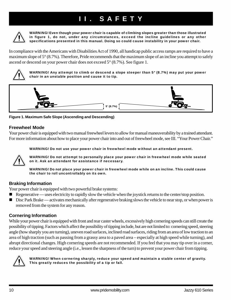
Figure 1. Maximum Safe Slope (Ascending and Descending)
5 (8.7%)
WARNING! Even though your power chair is capable of climbing slopes greater than those illustratedin figure 1, do not, under any circumstances, exceed the incline guidelines or any otherspecifications presented in this manual. Doing so could cause instability in your power chair.
In compliance with the Americans with Disabilities Act of 1990, all handicap public access ramps are required to have amaximum slope of 5° (8.7%). Therefore, Pride recommends that the maximum slope of an incline you attempt to safelyascend or descend on your power chair does not exceed 5° (8.7%). See figure 1.
WARNING! Any attempt to climb or descend a slope steeper than 5° (8.7%) may put your powerchair in an unstable position and cause it to tip.
Freewheel ModeYour power chair is equipped with two manual freewheel levers to allow for manual maneuverability by a trained attendant.For more information about how to place your power chair into and out of freewheel mode, see III. “Your Power Chair.”
WARNING! Do not use your power chair in freewheel mode without an attendant present.
WARNING! Do not attempt to personally place your power chair in freewheel mode while seatedon it. Ask an attendant for assistance if necessary.
WARNING! Do not place your power chair in freewheel mode while on an incline. This could causethe chair to roll uncontrollably on its own.
Braking InformationYour power chair is equipped with two powerful brake systems:! Regenerative — uses electricity to rapidly slow the vehicle when the joystick returns to the center/stop position.! Disc Park Brake — activates mechanically after regenerative braking slows the vehicle to near stop, or when power is
removed from the system for any reason.
Cornering InformationWhile your power chair is equipped with front and rear caster wheels, excessively high cornering speeds can still create thepossibility of tipping. Factors which affect the possibility of tipping include, but are not limited to: cornering speed, steeringangle (how sharply you are turning), uneven road surfaces, inclined road surfaces, riding from an area of low traction to anarea of high traction (such as passing from a grassy area to a paved area – especially at high speed while turning), andabrupt directional changes. High cornering speeds are not recommended. If you feel that you may tip over in a corner,reduce your speed and steering angle (i.e., lessen the sharpness of the turn) to prevent your power chair from tipping.
WARNING! When cornering sharply, reduce your speed and maintain a stable center of gravity.This greatly reduces the possibility of a tip or fall.

Jazzy 610 Series www.pridemobility.com 11
I I . S A F E T Y
Public Streets and Roadways
WARNING! You should not operate your power chair on public streets and roadways. Be awarethat it may be difficult for traffic to see you when you are seated on your power chair. Obey alllocal pedestrian traffic rules. Wait until your path is clear of traffic, and then proceed withextreme caution.
Outdoor Driving SurfacesYour power chair is designed to provide optimum stability under normal driving conditions—dry, level surfaces composedof concrete, blacktop, or asphalt. However, Pride recognizes that there will be times when you will encounter other surfacetypes. For this reason, your power chair is designed to perform admirably on packed soil, grass, and gravel. Feel free touse your power chair safely on lawns and in park areas.! Reduce your power chair’s speed when driving on uneven terrain and/or soft surfaces.! Avoid tall grass that can entangle the running gear.! Avoid loosely packed gravel and sand.! If you feel unsure about a driving surface, avoid that surface.
Inclement Weather PrecautionsExposure of your power chair to inclement weather conditions should be avoided whenever possible. If suddenly caughtup in rain, snow, severe cold or heat while operating your power chair, proceed to shelter at the earliest opportunity.Thoroughly dry your power chair before storing, charging, or operating your power chair.
WARNING! Operating in rain, snow, salt, mist/spray conditions, and on icy/slippery surfaces canhave an adverse affect on the electrical system. Maintain and store your power chair in a dry andclean condition.
WARNING! Prolonged exposure to hot or cold conditions may affect the temperature of upholsteredand non-upholstered items on the power chair, possibly resulting in skin irritation. Exercise cautionwhen using your power chair in extremely hot or cold conditions or when exposing your powerchair to direct sunlight for prolonged periods of time.
Stationary Obstacles (Steps, Curbs, etc.)Proceed with extreme caution when driving near raised surfaces, unprotected ledges and/or drop-offs (curbs, porches,stairs, etc.). Be sure your power chair is traveling perpendicular to any curb you are required to navigate. See figure 2.
Figure 2. Correct Curb Approach Figure 3. Incorrect Curb Approach

12 www.pridemobility.com Jazzy 610 Series
I I . S A F E T Y
WARNING! Do not attempt to have your power chair climb or descend an obstacle that is higherthan 2 in. (5 cm) unless you have the assistance of an attendant.
WARNING! Do not attempt to have your power chair proceed backward down any step, curb, orother obstacle. This may cause the power chair to tip.
Stairs and EscalatorsPower chairs are not designed to travel up or down stairs or escalators. Always use an elevator.
WARNING! Never use your power chair to negotiate steps or escalators.
Doors! Determine if the door opens toward or away from you.! Drive your power chair gently and slowly forward to push the door open. Or drive your power chair gently and slowly
backward to pull the door open.
ElevatorsModern elevators have a door edge safety mechanism that, when pushed, reopens the elevator door(s).! If you are in the doorway of an elevator when the door(s) begin to close, push on the rubber door edge or allow the
rubber door edge to contact the power chair and the door will reopen.! Use care that pocketbooks, packages, or power chair accessories do not become caught in elevator doors.
Lift/Elevation ProductsIf you will be traveling with your power chair, you may find it necessary to use a lift/elevation product to aid in transporta-tion. Pride recommends that you closely review the instructions, specifications, and safety information set forth by themanufacturer of the lift/elevation product before using that product.
WARNING! Never sit on your power chair when it is being used in connection with any type of lift/elevation product. Your power chair was not designed with such use in mind and any damage orinjury incurred from such use is not the responsibility of Pride.
Motor Vehicle TransportPride recommends that you do not remain seated in your power chair while traveling in a motor vehicle. The power chairshould be stowed in the trunk of a car or in the back of a truck or van with batteries removed and properly secured.
WARNING! Do not sit on your power chair while it is in a moving vehicle.
WARNING! Always be sure your power chair and its batteries are properly secured when it is beingtransported. Batteries should be secured in an upright position and protective caps should beinstalled on the battery terminals. Batteries should not be transported with any flammable orcombustible items.
Positioning BeltsYour authorized Pride Provider, therapist(s), and other healthcare professionals are responsible for determining your re-quirement for a positioning belt in order to operate your power chair safely.
WARNING! If you require a positioning belt to safely operate your power chair, make sure it isfastened securely in order to reduce the possibility of a fall from the power chair.
WARNING! The positioning belt is not designed for use as a seat belt in a motor vehicle. Nor isyour power chair suitable for use as a seat in any vehicle. Anyone traveling in a vehicle should beproperly belted into seats approved by the vehicle manufacturer.
Jazzy 610 Series www.pridemobility.com 13
I I . S A F E T Y
BatteriesIn addition to following the warnings below, be sure to comply with all other battery handling information. For moreinformation about your power chair’s batteries, see VI. “Batteries and Charging.”
WARNING! Power chair batteries are heavy. See specifications table. If you are unable to lift thatmuch weight, be sure to get help. Use proper lifting techniques and avoid lifting beyond yourcapacity.
WARNING! Battery posts, terminals, and related accessories contain lead and lead compounds.Wash hands after handling.
WARNING! Always protect the batteries from freezing and never charge a frozen battery. Charginga frozen battery may result in damage to the battery.
WARNING! Connect your battery harnesses in the proper manner. RED (+) cables must be connectedto positive (+) battery terminals/posts. BLACK (-) cables must be connected to negative (-) batteryterminals/posts. Protective caps should be installed over all battery terminals. REPLACE cablesimmediately if damaged.
Removable Parts
WARNING! Do not attempt to lift or move a power chair by any of its removable parts, including thearmrests, seat, foot riggings, controller, and shrouds.
Preventing Unintended Movement
WARNING! If you anticipate being seated in a stationary position for an extended period of time,turn off the power. This will prevent unexpected motion from inadvertent joystick contact. Thiswill also eliminate the possibility of unintended chair movement from electromagnetic (EM) sources.
Reaching and BendingNever reach, lean, or bend while driving your power chair. If it is absolutely necessary to reach, lean, or bend while seatedon your power chair, it is important to maintain a stable center of gravity and keep the power chair from tipping. Priderecommends that the power chair user determine his/her personal limitations and practice bending and reaching in thepresence of a qualified healthcare professional.
WARNING! Do not bend, lean, or reach for objects if you have to pick them up from the floor byreaching down between your knees or if you have to reach over the back of the seat. Movementssuch as these may change your center of gravity and the weight distribution of the power chair,possibly causing your power chair to tip.
WARNING! Keep your hands away from the tires when driving. Be aware that loose fitting clothingcan become caught in drive tires.
14 www.pridemobility.com Jazzy 610 Series
I I . S A F E T Y
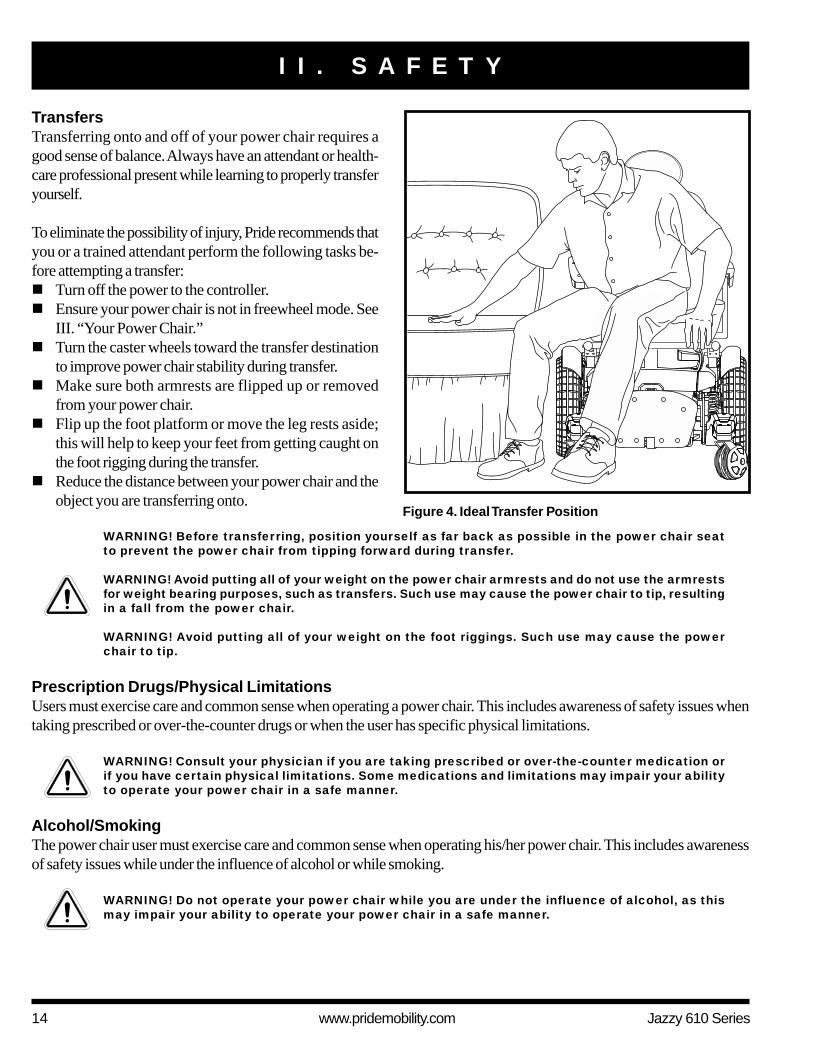
Figure 4. Ideal Transfer Position
TransfersTransferring onto and off of your power chair requires agood sense of balance. Always have an attendant or health-care professional present while learning to properly transferyourself.
To eliminate the possibility of injury, Pride recommends thatyou or a trained attendant perform the following tasks be-fore attempting a transfer:! Turn off the power to the controller.! Ensure your power chair is not in freewheel mode. See
III. “Your Power Chair.”! Turn the caster wheels toward the transfer destination
to improve power chair stability during transfer.! Make sure both armrests are flipped up or removed
from your power chair.! Flip up the foot platform or move the leg rests aside;
this will help to keep your feet from getting caught onthe foot rigging during the transfer.
! Reduce the distance between your power chair and theobject you are transferring onto.
WARNING! Before transferring, position yourself as far back as possible in the power chair seatto prevent the power chair from tipping forward during transfer.
WARNING! Avoid putting all of your weight on the power chair armrests and do not use the armrestsfor weight bearing purposes, such as transfers. Such use may cause the power chair to tip, resultingin a fall from the power chair.
WARNING! Avoid putting all of your weight on the foot riggings. Such use may cause the powerchair to tip.
Prescription Drugs/Physical LimitationsUsers must exercise care and common sense when operating a power chair. This includes awareness of safety issues whentaking prescribed or over-the-counter drugs or when the user has specific physical limitations.
WARNING! Consult your physician if you are taking prescribed or over-the-counter medication orif you have certain physical limitations. Some medications and limitations may impair your abilityto operate your power chair in a safe manner.
Alcohol/SmokingThe power chair user must exercise care and common sense when operating his/her power chair. This includes awarenessof safety issues while under the influence of alcohol or while smoking.
WARNING! Do not operate your power chair while you are under the influence of alcohol, as thismay impair your ability to operate your power chair in a safe manner.

Jazzy 610 Series www.pridemobility.com 15
WARNING! Although the power chair seat has passed the necessary testing requirements forcigarette smoke, Pride recommends that you adhere to the following safety guidelines:! Do not leave lit cigarettes unattended.! Keep ashtrays a safe distance from the seat cushions.! Always make sure cigarettes are completely extinguished before disposal.
Electromagnetic and Radio Frequency Interference (EMI/RFI)
WARNING! Laboratory tests have shown that electromagnetic and radio frequency waves canhave an adverse affect on the performance of electrically-powered mobility vehicles.
Electromagnetic and Radio Frequency Interference can come from sources such as cellular phones, mobile two-wayradios (such as walkie-talkies), radio stations, TV stations, amateur radio (HAM) transmitters, wireless computer links,microwave signals, paging transmitters, and medium-range mobile transceivers used by emergency vehicles. In somecases, these waves can cause unintended movement or damage to the control system. Every electrically-powered mobilityvehicle has an immunity (or resistance) to EMI. The higher the immunity level, the greater the protection against EMI. Thisproduct has been tested and has passed at an immunity level of 20 V/m.
WARNING! Be aware that cell phones, two-way radios, laptops, and other types of radio transmittersmay cause unintended movement of your electrically-powered mobility vehicle due to EMI.Exercise caution when using any of these items while operating your mobility vehicle and avoidcoming into close proximity of radio and TV stations.
WARNING! The addition of accessories or components to the electrically-powered mobility vehiclecan increase the susceptibility of the vehicle to EMI. Do not modify your power chair in any waynot authorized by Pride.
WARNING! The electrically-powered mobility vehicle itself can disturb the performance of otherelectrical devices located nearby, such as alarm systems.
NOTE: For further information on EMI/RFI, go to the Resource Center on www.pridemobility.com. Ifunintended motion or brake release occurs, turn your power chair off as soon as it is safe to do so. Call Prideat 800-424-8205 to report the incident.
I I . S A F E T Y
16 www.pridemobility.com Jazzy 610 Series
I I I . Y O U R P O W E R C H A I R
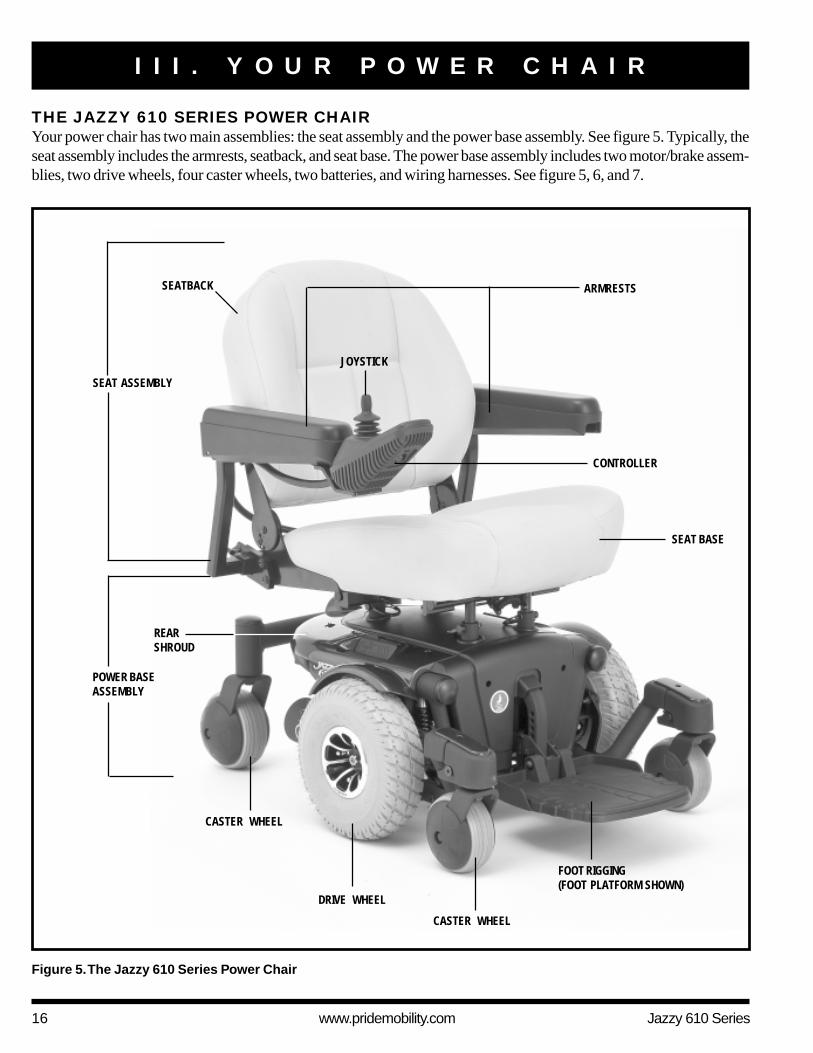
THE JAZZY 610 SERIES POWER CHAIRYour power chair has two main assemblies: the seat assembly and the power base assembly. See figure 5. Typically, theseat assembly includes the armrests, seatback, and seat base. The power base assembly includes two motor/brake assem-blies, two drive wheels, four caster wheels, two batteries, and wiring harnesses. See figure 5, 6, and 7.
SEATBACK
REARSHROUD
DRIVE WHEEL
CASTER WHEEL
Figure 5. The Jazzy 610 Series Power Chair
POWER BASEASSEMBLY
SEAT ASSEMBLY
JOYSTICK
FOOT RIGGING(FOOT PLATFORM SHOWN)
SEAT BASE
ARMRESTS
CONTROLLER
CASTER WHEEL

Jazzy 610 Series www.pridemobility.com 17
I I I . Y O U R P O W E R C H A I R
SPECIFICATIONS
Suspension: ATX Suspension (Active-Trac with extra stability)
Drive Wheels: 10 in. (25.4 cm), pneumatic or solid available
Front Caster Wheels: 5 in. (12.7 cm), solid
Rear Caster Wheels: 6 in. (15.24 cm), solid
Maximum Speed:¹ Up to 4 mph (6.43 km/h)
Range:1 Variable up to 10 miles (16 km)
Brakes: “Intelligent Braking” electronic regenerative, disc park brake
Ground Clearance:² 2.5 in. (6.35 cm)
Turning Radius:² 21.25 in. (54 cm)
Overall Size:² Length: 34.75 in. (88.26 cm) without foot riggings
Width: 23.25 in. (59 cm)
Drivetrain: Two motor, mid-wheel drive
Batteries:³ Two 12-volt, deep-cycle U-1 batteries
Battery Charger: 4-amp, onboard (standard)
4-amp onboard/5-amp off-board combo
Weight Capacity: 300 lbs. (136 kg)
250 lbs. (113 kg) with TRU-Balance 2 Power Tilt
Component Weights: Base: 109 lbs. (49.44 kg) without seat and batteries
Batteries: 24.5 lbs. (11.11 kg) each
¹ Varies with base model, user weight, terrain type, battery amp hour rating (AH), battery charge, battery condition, motors, controllertype, tire type, and tire condition.
² Due to manufacturing tolerances and continued product improvement, this specification can be subject to a variance of (+ or – ) 3%.³ AGM or Gel-Cell type recommended.
NOTE: All specifications subject to change without notice.
18 www.pridemobility.com Jazzy 610 Series
I I I . Y O U R P O W E R C H A I R
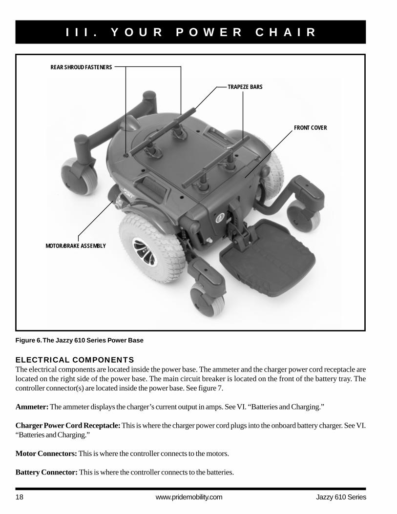
ELECTRICAL COMPONENTSThe electrical components are located inside the power base. The ammeter and the charger power cord receptacle arelocated on the right side of the power base. The main circuit breaker is located on the front of the battery tray. Thecontroller connector(s) are located inside the power base. See figure 7.
Ammeter: The ammeter displays the charger’s current output in amps. See VI. “Batteries and Charging.”
Charger Power Cord Receptacle: This is where the charger power cord plugs into the onboard battery charger. See VI.“Batteries and Charging.”
Motor Connectors: This is where the controller connects to the motors.
Battery Connector: This is where the controller connects to the batteries.
Figure 6. The Jazzy 610 Series Power Base
MOTOR/BRAKE ASSEMBLY
REAR SHROUD FASTENERS
TRAPEZE BARS
FRONT COVER
Jazzy 610 Series www.pridemobility.com 19
I I I . Y O U R P O W E R C H A I R
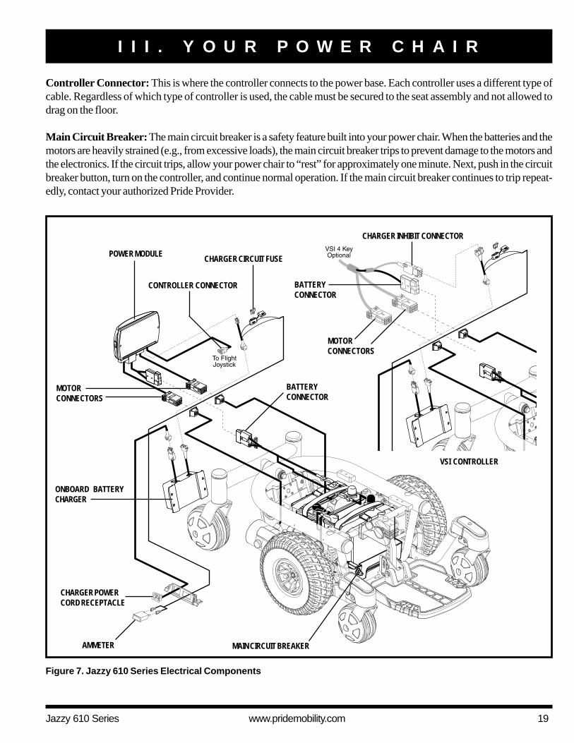
Controller Connector: This is where the controller connects to the power base. Each controller uses a different type ofcable. Regardless of which type of controller is used, the cable must be secured to the seat assembly and not allowed todrag on the floor.
Main Circuit Breaker: The main circuit breaker is a safety feature built into your power chair. When the batteries and themotors are heavily strained (e.g., from excessive loads), the main circuit breaker trips to prevent damage to the motors andthe electronics. If the circuit trips, allow your power chair to “rest” for approximately one minute. Next, push in the circuitbreaker button, turn on the controller, and continue normal operation. If the main circuit breaker continues to trip repeat-edly, contact your authorized Pride Provider.
Figure 7. Jazzy 610 Series Electrical Components
BATTERYCONNECTOR
CHARGER POWERCORD RECEPTACLE
CHARGER CIRCUIT FUSE
ONBOARD BATTERYCHARGER
MAIN CIRCUIT BREAKERAMMETER
POWER MODULE
MOTORCONNECTORS
CHARGER INHIBIT CONNECTOR
BATTERYCONNECTOR
VSI CONTROLLER
CONTROLLER CONNECTOR
MOTORCONNECTORS
20 www.pridemobility.com Jazzy 610 Series
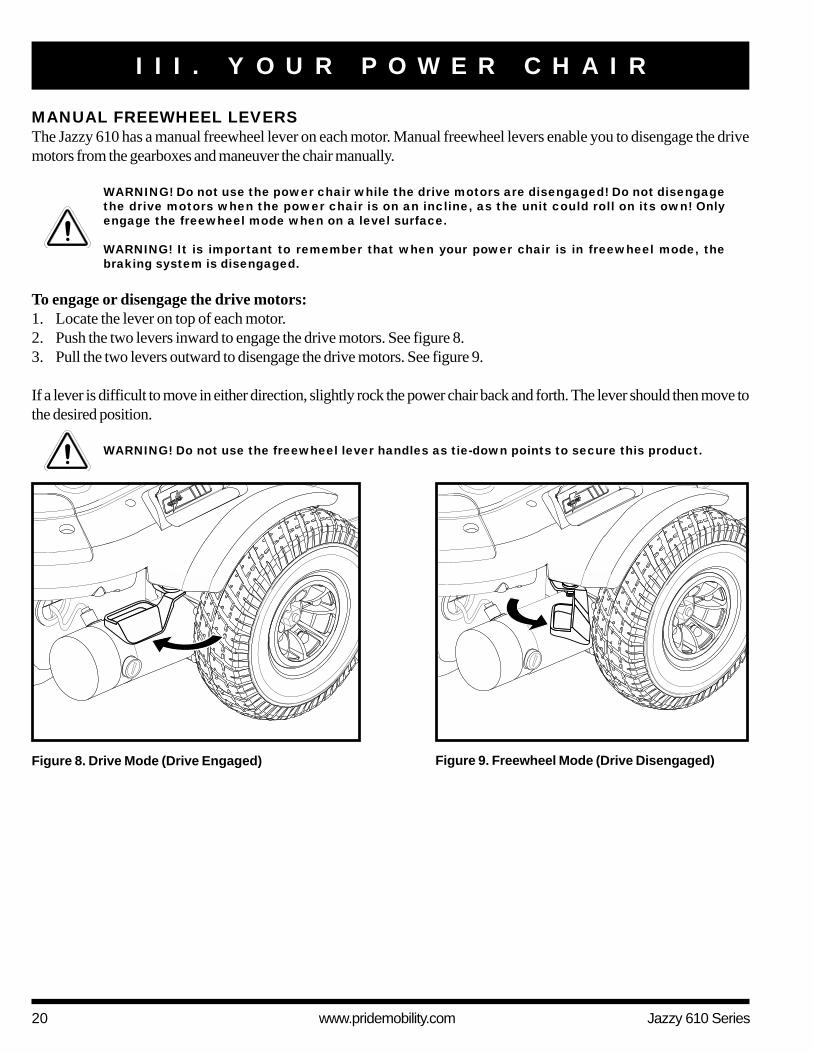
MANUAL FREEWHEEL LEVERSThe Jazzy 610 has a manual freewheel lever on each motor. Manual freewheel levers enable you to disengage the drivemotors from the gearboxes and maneuver the chair manually.
WARNING! Do not use the power chair while the drive motors are disengaged! Do not disengagethe drive motors when the power chair is on an incline, as the unit could roll on its own! Onlyengage the freewheel mode when on a level surface.
WARNING! It is important to remember that when your power chair is in freewheel mode, thebraking system is disengaged.
To engage or disengage the drive motors:1. Locate the lever on top of each motor.2. Push the two levers inward to engage the drive motors. See figure 8.3. Pull the two levers outward to disengage the drive motors. See figure 9.
If a lever is difficult to move in either direction, slightly rock the power chair back and forth. The lever should then move tothe desired position.
WARNING! Do not use the freewheel lever handles as tie-down points to secure this product.
I I I . Y O U R P O W E R C H A I R
Figure 9. Freewheel Mode (Drive Disengaged)Figure 8. Drive Mode (Drive Engaged)
Jazzy 610 Series www.pridemobility.com 21
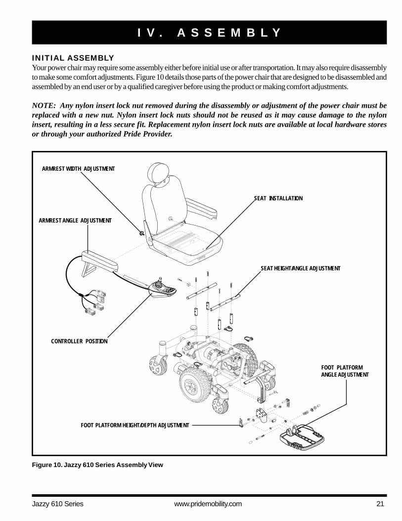
INITIAL ASSEMBLYYour power chair may require some assembly either before initial use or after transportation. It may also require disassemblyto make some comfort adjustments. Figure 10 details those parts of the power chair that are designed to be disassembled andassembled by an end user or by a qualified caregiver before using the product or making comfort adjustments.
NOTE: Any nylon insert lock nut removed during the disassembly or adjustment of the power chair must bereplaced with a new nut. Nylon insert lock nuts should not be reused as it may cause damage to the nyloninsert, resulting in a less secure fit. Replacement nylon insert lock nuts are available at local hardware storesor through your authorized Pride Provider.
I V . A S S E M B L Y
ARMREST ANGLE ADJUSTMENT
SEAT INSTALLATION
ARMREST WIDTH ADJUSTMENT
Figure 10. Jazzy 610 Series Assembly View
FOOT PLATFORM HEIGHT/DEPTH ADJUSTMENT
SEAT HEIGHT/ANGLE ADJUSTMENT
CONTROLLER POSITION
FOOT PLATFORMANGLE ADJUSTMENT
22 www.pridemobility.com Jazzy 610 Series
I V . A S S E M B L Y
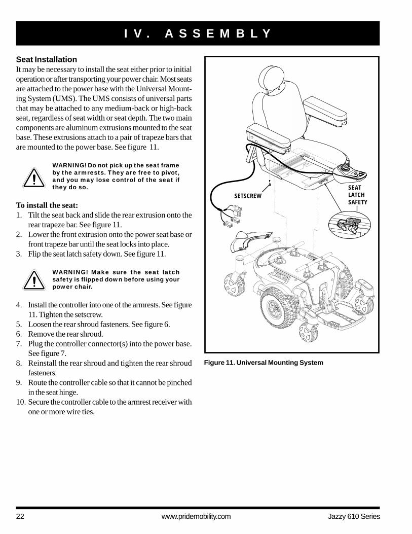
Seat InstallationIt may be necessary to install the seat either prior to initialoperation or after transporting your power chair. Most seatsare attached to the power base with the Universal Mount-ing System (UMS). The UMS consists of universal partsthat may be attached to any medium-back or high-backseat, regardless of seat width or seat depth. The two maincomponents are aluminum extrusions mounted to the seatbase. These extrusions attach to a pair of trapeze bars thatare mounted to the power base. See figure 11.
WARNING! Do not pick up the seat frameby the armrests. They are free to pivot,and you may lose control of the seat ifthey do so.
To install the seat:1. Tilt the seat back and slide the rear extrusion onto the
rear trapeze bar. See figure 11.2. Lower the front extrusion onto the power seat base or
front trapeze bar until the seat locks into place.3. Flip the seat latch safety down. See figure 11.
WARNING! Make sure the seat latchsafety is flipped down before using yourpower chair.
4. Install the controller into one of the armrests. See figure11. Tighten the setscrew.
5. Loosen the rear shroud fasteners. See figure 6.6. Remove the rear shroud.7. Plug the controller connector(s) into the power base.
See figure 7.8. Reinstall the rear shroud and tighten the rear shroud
fasteners.9. Route the controller cable so that it cannot be pinched
in the seat hinge.10. Secure the controller cable to the armrest receiver with
one or more wire ties.
Figure 11. Universal Mounting System
SETSCREWSEATLATCHSAFETY
Jazzy 610 Series www.pridemobility.com 23
V . C O M F O R T A D J U S T M E N T S
COMFORT ADJUSTMENTSAfter becoming familiar with your power chair’s operation, you may find the need to make some adjustments to increaseyour comfort, such as seat height and angle, armrest angle, foot platform height and angle, and controller position.
NOTE: If your power chair is equipped with a Synergy Seat, Specialty Seat, or TRU-Balance Power Position-ing System, refer to the seat adjustment information contained in separate manuals. If your power chair isequipped with a contoured seating system, refer to the following information.
WARNING! If your power chair was configured by your authorized Pride Provider, please consultyour healthcare professional before changing the seat position or making any other adjustment.Some adjustments may degrade your power chair’s performance and safety by changing its centerof gravity.
WARNING! Some power chair components are heavy. You may need assistance to lift or carrythem. Please refer to the specifications table for specific component weights before youdisassemble the power chair.
WARNING! Remove the occupant from the power chair before making any adjustments.
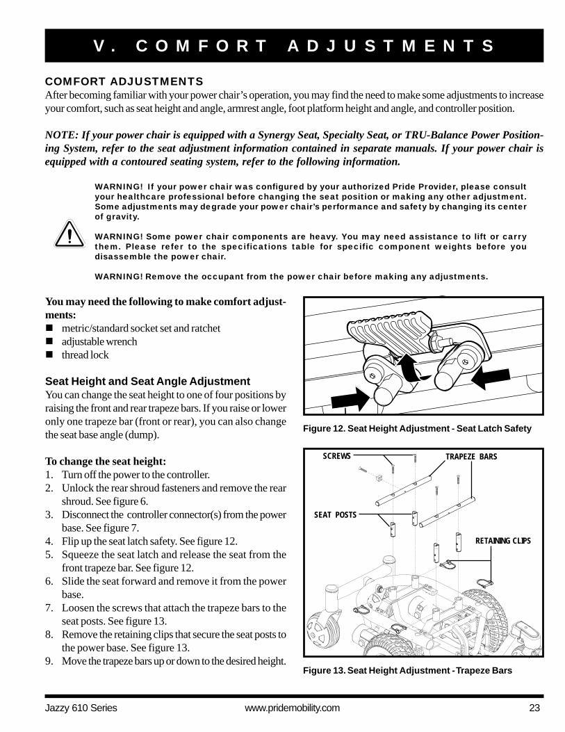
TRAPEZE BARS
RETAINING CLIPS
SEAT POSTS
Figure 13. Seat Height Adjustment - Trapeze Bars
SCREWS
Figure 12. Seat Height Adjustment - Seat Latch Safety
You may need the following to make comfort adjust-ments:! metric/standard socket set and ratchet! adjustable wrench! thread lock
Seat Height and Seat Angle AdjustmentYou can change the seat height to one of four positions byraising the front and rear trapeze bars. If you raise or loweronly one trapeze bar (front or rear), you can also changethe seat base angle (dump).
To change the seat height:1. Turn off the power to the controller.2. Unlock the rear shroud fasteners and remove the rear
shroud. See figure 6.3. Disconnect the controller connector(s) from the power
base. See figure 7.4. Flip up the seat latch safety. See figure 12.5. Squeeze the seat latch and release the seat from the
front trapeze bar. See figure 12.6. Slide the seat forward and remove it from the power
base.7. Loosen the screws that attach the trapeze bars to the
seat posts. See figure 13.8. Remove the retaining clips that secure the seat posts to
the power base. See figure 13.9. Move the trapeze bars up or down to the desired height.
24 www.pridemobility.com Jazzy 610 Series
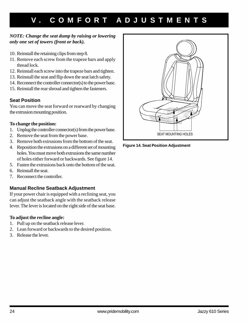
Figure 14. Seat Position Adjustment
V . C O M F O R T A D J U S T M E N T S
NOTE: Change the seat dump by raising or loweringonly one set of towers (front or back).
10. Reinstall the retaining clips from step 8.11. Remove each screw from the trapeze bars and apply
thread lock.12. Reinstall each screw into the trapeze bars and tighten.13. Reinstall the seat and flip down the seat latch safety.14. Reconnect the controller connector(s) to the power base.15. Reinstall the rear shroud and tighten the fasteners.
Seat PositionYou can move the seat forward or rearward by changingthe extrusion mounting position.
To change the position:1. Unplug the controller connector(s) from the power base.2. Remove the seat from the power base.3. Remove both extrusions from the bottom of the seat.4. Reposition the extrusions on a different set of mounting
holes. You must move both extrusions the same numberof holes either forward or backwards. See figure 14.
5. Fasten the extrusions back onto the bottom of the seat.6. Reinstall the seat.7. Reconnect the controller.
Manual Recline Seatback AdjustmentIf your power chair is equipped with a reclining seat, youcan adjust the seatback angle with the seatback releaselever. The lever is located on the right side of the seat base.
To adjust the recline angle:1. Pull up on the seatback release lever.2. Lean forward or backwards to the desired position.3. Release the lever.

Jazzy 610 Series www.pridemobility.com 25
Seatback Angle AdjustmentIf your power chair is equipped with an adjustable seatback,you can adjust it to four (4) different angles: 90°, 102°,105°, or 107°.
To adjust the seatback angle:1. Remove the adjusting screws from each seat hinge. See
figure 15.2. Set the seatback at the desired angle.3. Reinstall the adjusting screws to each seat hinge and
tighten.
Armrest Width AdjustmentYou can change each armrest’s width independently of the other.
NOTE: Changing the armrest width may increase theoverall width of your power chair.
To change the armrest width:1. Locate the two armrest knobs on each side of the arm-
rest receiver bracket. See figure 15.2. Loosen the knobs.3. Slide the armrests in or out to the desired width.4. Tighten the knobs.
Armrest Angle AdjustmentTo change the armrest angle:1. Lift the armrest straight up so that it is perpendicular to
the floor. See figure 15.2. Loosen the jam nut.3. Turn the adjusting screw to raise the front of the arm-
rest or to lower the front of the armrest.4. Tighten the jam nut to lock the adjusting screw into
place.
Armrest Height AdjustmentTo change the armrest height:1. Loosen the two setscrews located on the armrest receiver.2. Raise or lower the armrest to the desired height.3. Tighten the setscrews to secure the armrest.
V . C O M F O R T A D J U S T M E N T S
Figure 15. Seatback/Armrest Adjustment
ARMREST KNOB
JAM NUT
SEATBACK ANGLEADJUSTING SCREW
ARMREST HEIGHTADJUSTINGSETSCREWS
ARMREST ANGLEADJUSTING SCREW
26 www.pridemobility.com Jazzy 610 Series
V . C O M F O R T A D J U S T M E N T S
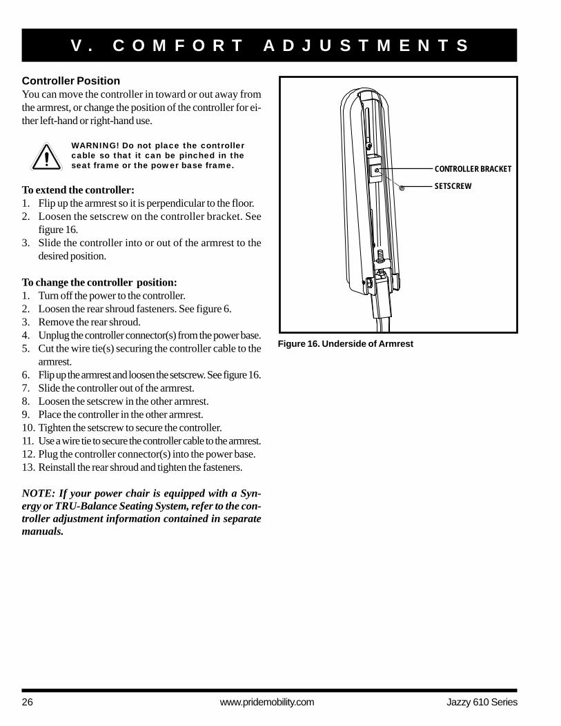
Controller PositionYou can move the controller in toward or out away fromthe armrest, or change the position of the controller for ei-ther left-hand or right-hand use.
WARNING! Do not place the controllercable so that it can be pinched in theseat frame or the power base frame.
To extend the controller:1. Flip up the armrest so it is perpendicular to the floor.2. Loosen the setscrew on the controller bracket. See
figure 16.3. Slide the controller into or out of the armrest to the
desired position.
To change the controller position:1. Turn off the power to the controller.2. Loosen the rear shroud fasteners. See figure 6.3. Remove the rear shroud.4. Unplug the controller connector(s) from the power base.5. Cut the wire tie(s) securing the controller cable to the
armrest.6. Flip up the armrest and loosen the setscrew. See figure 16.7. Slide the controller out of the armrest.8. Loosen the setscrew in the other armrest.9. Place the controller in the other armrest.10. Tighten the setscrew to secure the controller.11. Use a wire tie to secure the controller cable to the armrest.12. Plug the controller connector(s) into the power base.13. Reinstall the rear shroud and tighten the fasteners.
NOTE: If your power chair is equipped with a Syn-ergy or TRU-Balance Seating System, refer to the con-troller adjustment information contained in separatemanuals.
SETSCREW
Figure 16. Underside of Armrest
CONTROLLER BRACKET
Jazzy 610 Series www.pridemobility.com 27
V . C O M F O R T A D J U S T M E N T S
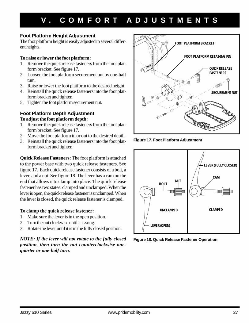
Foot Platform Height AdjustmentThe foot platform height is easily adjusted to several differ-ent heights.
To raise or lower the foot platform:1. Remove the quick release fasteners from the foot plat-
form bracket. See figure 17.2. Loosen the foot platform securement nut by one-half
turn.3. Raise or lower the foot platform to the desired height.4. Reinstall the quick release fasteners into the foot plat-
form bracket and tighten.5. Tighten the foot platform securement nut.
Foot Platform Depth AdjustmentTo adjust the foot platform depth:1. Remove the quick release fasteners from the foot plat-
form bracket. See figure 17.2. Move the foot platform in or out to the desired depth.3. Reinstall the quick release fasteners into the foot plat-
form bracket and tighten.
Quick Release Fasteners: The foot platform is attachedto the power base with two quick release fasteners. Seefigure 17. Each quick release fastener consists of a bolt, alever, and a nut. See figure 18. The lever has a cam on theend that allows it to clamp into place. The quick releasefastener has two states: clamped and unclamped. When thelever is open, the quick release fastener is unclamped. Whenthe lever is closed, the quick release fastener is clamped.
To clamp the quick release fastener:1. Make sure the lever is in the open position.2. Turn the nut clockwise until it is snug.3. Rotate the lever until it is in the fully closed position.
NOTE: If the lever will not rotate to the fully closedposition, then turn the nut counterclockwise one-quarter or one-half turn.
Figure 17. Foot Platform Adjustment
FOOT PLATFORM BRACKET
FOOT PLATFORM RETAINING PIN
QUICK RELEASEFASTENERS
Figure 18. Quick Release Fastener Operation
LEVER (OPEN)
BOLTNUT
CAM
UNCLAMPED CLAMPED
LEVER (FULLY CLOSED)
SECUREMENT NUT
28 www.pridemobility.com Jazzy 610 Series
V . C O M F O R T A D J U S T M E N T S
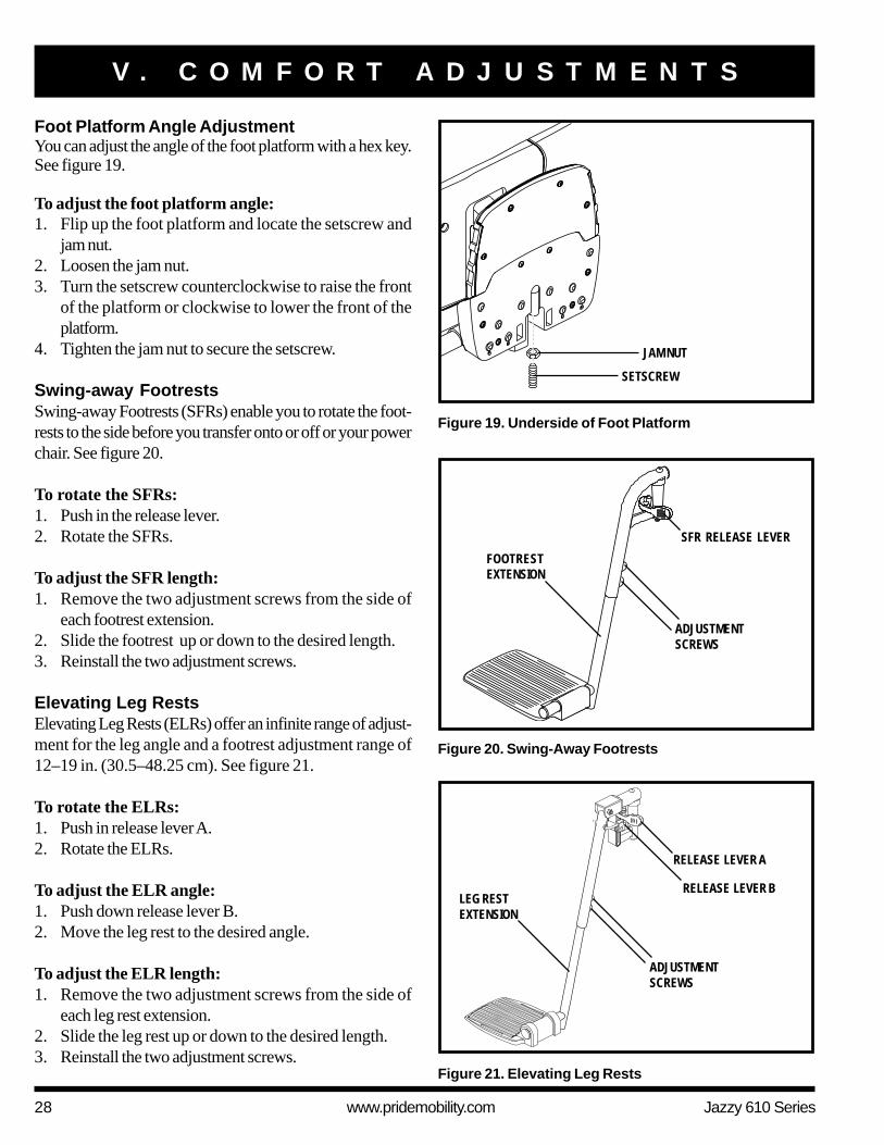
Foot Platform Angle AdjustmentYou can adjust the angle of the foot platform with a hex key.See figure 19.
To adjust the foot platform angle:1. Flip up the foot platform and locate the setscrew and
jam nut.2. Loosen the jam nut.3. Turn the setscrew counterclockwise to raise the front
of the platform or clockwise to lower the front of theplatform.
4. Tighten the jam nut to secure the setscrew.
Swing-away FootrestsSwing-away Footrests (SFRs) enable you to rotate the foot-rests to the side before you transfer onto or off or your powerchair. See figure 20.
To rotate the SFRs:1. Push in the release lever.2. Rotate the SFRs.
To adjust the SFR length:1. Remove the two adjustment screws from the side of
each footrest extension.2. Slide the footrest up or down to the desired length.3. Reinstall the two adjustment screws.
Elevating Leg RestsElevating Leg Rests (ELRs) offer an infinite range of adjust-ment for the leg angle and a footrest adjustment range of12–19 in. (30.5–48.25 cm). See figure 21.
To rotate the ELRs:1. Push in release lever A.2. Rotate the ELRs.
To adjust the ELR angle:1. Push down release lever B.2. Move the leg rest to the desired angle.
To adjust the ELR length:1. Remove the two adjustment screws from the side of
each leg rest extension.2. Slide the leg rest up or down to the desired length.3. Reinstall the two adjustment screws.
Figure 19. Underside of Foot Platform
SETSCREW
JAM NUT
Figure 20. Swing-Away Footrests
ADJUSTMENTSCREWS
FOOTRESTEXTENSION
SFR RELEASE LEVER
ADJUSTMENTSCREWS
RELEASE LEVER B
Figure 21. Elevating Leg Rests
RELEASE LEVER A
LEG RESTEXTENSION
Jazzy 610 Series www.pridemobility.com 29
A
C
D
B
B
C
D
A
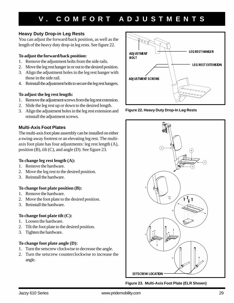
Figure 23. Multi-Axis Foot Plate (ELR Shown)
SETSCREW LOCATION
V . C O M F O R T A D J U S T M E N T S
Heavy Duty Drop-in Leg RestsYou can adjust the forward/back position, as well as thelength of the heavy duty drop-in leg rests. See figure 22.
To adjust the forward/back position:1. Remove the adjustment bolts from the side rails.2. Move the leg rest hanger in or out to the desired position.3. Align the adjustment holes in the leg rest hanger with
those in the side rail.4. Reinstall the adjustment bolts to secure the leg rest hangers.
To adjust the leg rest length:1. Remove the adjustment screws from the leg rest extension.2. Slide the leg rest up or down to the desired length.3. Align the adjustment holes in the leg rest extension and
reinstall the adjustment screws.
Multi-Axis Foot PlatesThe multi-axis foot plate assembly can be installed on eithera swing-away footrest or an elevating leg rest. The multi-axis foot plate has four adjustments: leg rest length (A),position (B), tilt (C), and angle (D). See figure 23.
To change leg rest length (A):1. Remove the hardware.2. Move the leg rest to the desired position.3. Reinstall the hardware.
To change foot plate position (B):1. Remove the hardware.2. Move the foot plate to the desired position.3. Reinstall the hardware.
To change foot plate tilt (C):1. Loosen the hardware.2. Tilt the foot plate to the desired position.3. Tighten the hardware.
To change foot plate angle (D):1. Turn the setscrew clockwise to decrease the angle.2. Turn the setscrew counterclockwise to increase the
angle.
Figure 22. Heavy Duty Drop-In Leg Rests
ADJUSTMENTBOLT
ADJUSTMENT SCREWS
LEG REST HANGER
LEG REST EXTENSION

30 www.pridemobility.com Jazzy 610 Series
V I . B A T T E R I E S A N D C H A R G I N G
BATTERIES AND CHARGINGYour power chair uses two long-lasting, 12-volt, deep-cycle batteries. These batteries are sealed and maintenance free.Since they are sealed, there is no need to check the electrolyte (fluid) level. Deep-cycle batteries are designed to handle alonger and deeper discharge. Though they are similar in appearance to automotive batteries, they are not interchangeable.Automotive batteries are not designed to handle a long, deep discharge, and also are unsafe for use in power chairs.
WARNING! Battery posts, terminals, and related accessories contain lead and lead compounds.Wash hands after handling.
WARNING! Do not use batteries that exceed the recommended type and amp-hour capacity. Donot use batteries with different amp-hour capacities. Refer to specifications table in this manualand in the manual suppled with the battery charger for recommended type and capacities.
Charging the BatteriesThe battery charger is essential in providing long life for your power chair batteries. It is designed to optimize your powerchair’s performance by charging the batteries safely, quickly, and easily. The battery charging system consists of theonboard battery charger, the charger circuit fuse, and the ammeter. The ammeter indicates the rate of charge necessary tofully recharge the batteries. It is also a good indication of whether or not the charger is working. The ammeter and thecharger are only functional when the charger power cord is plugged into an electrical outlet. The charger circuit has an ATOfuse that protects the ammeter. See figure 7.
PROHIBITED! Removal of grounding prong can create electrical hazard. If necessary, properlyinstall an approved 3-pronged adapter to an electrical outlet having 2-pronged plug access.
PROHIBITED! Never use an extension cord to plug in your battery charger. Plug the charger directlyinto a properly wired standard electrical outlet.
WARNING! You must recharge your power chair’s batteries with the supplied onboard batterycharger or optional off-board battery charger. Do not use an automotive-type battery charger.
WARNING! Read the battery charging instructions in this manual and in the manual supplied withthe battery charger before charging the batteries.
WARNING! Do not expose the battery charger to rain or other sources of moisture unless it hasbeen tested for outdoor use. Refer to the manual supplied with the battery charger for moreinformation.
WARNING! Explosive gases may be generated while charging the batteries. Keep the power chairand battery charger away from sources of ignition such as flames or sparks and provide adequateventilation when charging the batteries.
WARNING! Inspect the battery charger, wiring, and connectors for damage before each use. Contactyour authorized Pride Provider if damage is found.
WARNING! Do not attempt to open the battery charger case. If the battery charger does notappear to be working correctly, contact your authorized Pride Provider.
WARNING! If the battery charger is equipped with cooling slots, then do not attempt to insertobjects through these slots.
WARNING! Do not allow unsupervised children to play near the power chair while the batteriesare charging. Pride recommends that you do not charge the batteries while the power chair isoccupied.

Jazzy 610 Series www.pridemobility.com 31
V I . B A T T E R I E S A N D C H A R G I N G
WARNING! If your battery charger has not been tested and approved for outdoor use, then do notexpose it to adverse or extreme weather conditions. If the battery charger is exposed to adverseor extreme weather conditions, then it must be allowed to adjust to the difference in environmentalconditions before use indoors. Refer to the manual supplied with the battery charger for moreinformation.
To charge the batteries using the onboard charger:1. Position the rear of your power chair close to a standard electrical outlet.2. Be certain the controller power is turned off and the freewheel levers are in the drive mode position. See III. “Your
Power Chair.”3. Plug the charger power cord into the charger power cord receptacle on the power base, then into the electrical outlet.
NOTE: The power chair incorporates an inhibit function that disables the power chair when the charger isplugged into an electrical outlet.
4. We recommend you charge the batteries for 8 to 14 hours. As the batteries charge, the ammeter needle slowly dropsto 0.
NOTE: The ammeter indicates how much charge is needed to fully charge the batteries. Wait about a minutefor the charger to warm up. The ammeter may move as high as 5.5 amps, then gradually move back down to 0amps as the batteries charge.
5. When the batteries are fully charged, the needle vibrates on or about the 0 mark on the ammeter. Disconnect thecharger power cord, wind up the cord, and store it in a safe place.
To charge the batteries using the optional off-board charger:1. Position the front of your power chair next to a standard electrical outlet.2. Be certain the controller power is turned off.3. Plug the off-board charger into the off-board charger/programming socket on the controller.4. Plug the off-board charger into the electrical outlet.
NOTE: If it is a Pride off-board charger, then there are two lights in it. The red light indicates that power tothe off-board charger is on. The green light indicates that the batteries are fully charged. If it is not a Pride off-board charger, then follow the instructions supplied by the manufacturer.
5. When the batteries are fully charged, unplug the off-board charger from the electrical outlet and then from the controller.
Battery Break-inTo break in new batteries for maximum efficiency:1. Fully recharge any new battery prior to its initial use. This brings the battery up to about 90% of its peak performance
level.2. Operate your power chair throughout the house and yard. Move slowly at first, and do not travel too far until you
become accustomed to the controls and break in the batteries.3. Give the batteries another full charge of 8 to 14 hours and operate your power chair again. The batteries will now
perform at over 90% of their potential.4. After four or five charging cycles, the batteries will top off at 100% charge and last for an extended period.

32 www.pridemobility.com Jazzy 610 Series
V I . B A T T E R I E S A N D C H A R G I N G
Frequently Asked Questions (FAQs)
How does the charger work?The battery charger takes the standard electrical outlet voltage (alternating current) and converts it to 24 VDC (directcurrent). The power chair batteries use direct current to run your power chair. When the battery voltage is low, the chargerworks harder to charge the battery. As the battery voltage approaches full charge, the charger doesn’t work as hard tocomplete the charging cycle. When the battery is fully charged, the amperage from the charger is nearly at zero. This is howthe charger maintains a charge but does not overcharge the battery.
Can I use a different battery charger?You should use the charger supplied with the power chair. It is the safest, most efficient tool to charge the batteries. We donot recommend using other types of chargers (e.g., an automotive battery charger).
NOTE: Your power chair’s charger will not operate after the batteries have been discharged to nearly zerovoltage. If this happens, call your authorized Pride Provider for assistance.
How often must I charge the batteries?Many factors come into play when deciding how often to charge the batteries. You may use your power chair all day on adaily basis or you may not use it for weeks at a time.
! Daily UseIf you use your power chair on a daily basis, charge the batteries as soon as you are finished using your power chair.Your power chair will be ready each morning to give you a full day’s service. It is recommended that you charge thebatteries 8 to 14 hours after daily use.
! Infrequent UseIf you use your power chair infrequently (once a week or less), you should charge the batteries at least once per weekfor 12 to 14 hours.
NOTE: Keep your batteries fully charged and avoid deeply discharging your batteries. Do not charge thebatteries for more than 24 hours at a charging cycle.
How can I get maximum range or distance per charge?Rarely do you have an ideal driving situation such as smooth, flat, hard terrain with no wind, hills, or curves. More oftenyou are presented with hills, sidewalk cracks, uneven and loosely packed surfaces, curves, and wind. All of thesefactors will affect the distance or running time per battery charge. Below are a few suggestions for obtaining the maxi-mum range per charge:! Always charge the batteries fully prior to your trip.! Plan your trip in advance to avoid inclines if possible.! Limit baggage weight to essential items.! Try to maintain an even speed and avoid stop-and-go driving.
What type of batteries should I use?We recommend deep-cycle batteries that are sealed and maintenance free. Both AGM and Gel-Cell are deep-cyclebatteries that are similar in performance. Refer to the Specifications Table for more information regarding the batteries usedwith your power chair.

Jazzy 610 Series www.pridemobility.com 33
WARNING! Corrosive chemicals contained in batteries. Use only AGM or Gel-Cell batteries toreduce the risk of leakage or explosive conditions.
Why do my new batteries seem weak?Deep-cycle batteries employ a much different chemical technology than that used in car batteries, nickel-cadmium (nicads),or in other common battery types. Deep-cycle batteries are specifically designed to provide power, drain down theircharge, and then accept a relatively quick recharge. AGM and Gel-Cell batteries should be charged as often as possible.They do not have a “memory” like nickel-cadmium batteries.
We work closely with our battery manufacturer to provide a battery that best suits your power chair’s specific demands.Fresh batteries arrive regularly at Pride and are promptly shipped with a full charge. During shipping, the batteries encoun-ter temperature extremes that may influence initial performance. Heat robs the charge from the battery, and cold slows thepower available and extends the time needed to recharge the battery (just as with a car battery).
It might take a few days for the temperature of the battery to stabilize and adjust to its new ambient temperature. Moreimportantly, it will take a few “charging cycles” (a partial drain— then a full recharge) to establish the critical chemicalbalance that is essential to the battery’s peak performance and long life. It will be well worth it to take the time to break inyour battery properly.
NOTE: The useful life of a battery is quite often a reflection of the care it receives.
How can I ensure maximum battery life?A fully charged deep-cycle battery will provide reliable performance and extended battery life. Keep your power chair’sbatteries fully charged whenever possible. Batteries that are regularly and deeply discharged, infrequently charged, orstored without a full charge may be permanently damaged, causing unreliable power chair operation and limited battery life.
How should I store my power chair and its batteries?If you do not use your power chair regularly, we recommend maintaining battery vitality by charging the batteries at leastonce per week.
If you do not plan on using your power chair for an extended period, fully charge the batteries prior to storage. Disconnectthe battery harnesses and store the power chair in a warm, dry environment. Avoid temperature extremes, such as freezingand excessively hot conditions, and never attempt to charge a frozen battery. A cold or frozen battery should be warmedfor several days prior to recharging.
What about public transportation?AGM and Gel-Cell batteries are designed for application in power chairs and other mobility vehicles. These batteries areFederal Aviation Administration (FAA) approved, allowing safe transportation on aircraft, buses, and trains, as there is nodanger of spillage or leakage. We suggest you contact the carrier’s ticket counter in advance to determine that carrier’sspecific requirements.
What about shipping?If you wish to use a freight company to ship your power chair to your final destination, repack your power chair in theoriginal shipping container and ship the batteries in separate boxes.
V I . B A T T E R I E S A N D C H A R G I N G

34 www.pridemobility.com Jazzy 610 Series
V I I . C A R E A N D M A I N T E N A N C E
CARE AND MAINTENANCEYour Jazzy 610 is a sophisticated power chair. Like any motorized vehicle, it requires routine maintenance checks. You canperform some of these checks, but others require assistance from your authorized Pride Provider. Preventive maintenanceis very important. If you follow the maintenance checks in this section as scheduled, you can help ensure that your powerchair gives you years of trouble-free operation. If you have any doubt as to your power chair’s care or operation, contactyour authorized Pride Provider.
WARNING! Do not service the power chair when the seat is occupied.
Your power chair, like most electrical equipment, is susceptible to damage from the elements. Avoid damp areas of any kind.
WARNING! Direct or prolonged exposure to water or dampness could cause the power chair tomalfunction electronically and mechanically. Water can cause electrical components to corrodeand the chair's frame to rust. Power chairs should be examined periodically for signs of corrosioncaused by water exposure, bodily fluid exposure, or incontinence. Damaged components shouldbe replaced or treated immediately.
Should your power chair come in contact with water:1. Dry your power chair as thoroughly as possible with a towel.2. Allow your power chair to sit in a warm, dry place for 12 hours to allow unseen water to evaporate.3. Check the joystick operation and the brakes before using your power chair again.4. If any inconsistencies are found, take your power chair to your authorized Pride Provider. Power chairs that are
frequently exposed to sources of water, such as incontinence, should be inspected often for corrosion and electroniccomponents may need to be replaced frequently.
Temperature! Some of the parts of your power chair are susceptible to extreme changes in temperature. Always keep your power
chair between the temperatures of 18°F (-8°C) and 122°F (50°C).! In extremely cold temperatures the batteries may freeze. The specific temperature at which they freeze depends on a
number of factors, such as battery charge, usage, and composition of the batteries (e.g., AGM or Gel-Cell).! Temperatures above 122°F (50°C) may cause your power chair to operate at a reduced speed. This reduced speed
is a safety feature built into the controller that helps prevent damage to the motor and other electrical components.
General Guidelines! Avoid knocking or bumping the controller, especially the joystick.! Avoid prolonged exposure of your power chair to extreme conditions, such as heat, cold, or moisture.! Keep the controller clean.! Check all connectors to ensure that they are all tight and secured properly.! Make sure pneumatic drive tires are inflated to 35 psi (2.4 bar).
WARNING! Make sure your tires are inflated to 35 psi (2.4 bar). Do not underinflate or overinflateyour tires. Low pressure may result in loss of control, and overinflated tires may burst. Overinflatingtires can cause them to explode.
WARNING! Do not use a high pressure hose to inflate your tires.
! Use a rubber conditioner on the tire sidewalls to help preserve them.
WARNING! Never use a rubber conditioner on the tread area of the tires; doing so may make thetires slippery and cause your power chair to skid.

Jazzy 610 Series www.pridemobility.com 35
V I I . C A R E A N D M A I N T E N A N C E
! All wheel bearings are prelubricated and sealed. They require no subsequent lubrication.! The body shroud has been sprayed with a clear sealant coating. You can apply a light coat of car wax to help it retain
its high-gloss appearance.! Check all electrical connections. Make sure they are tight and are not corroded. Batteries must sit flat within the
battery tray, with the battery terminals facing inward, toward each other. Refer to the battery wiring label for thecorrect wiring layout.
WARNING! Even though the power chair has passed the necessary testing requirements for ingressof liquids, you should keep electrical connections away from sources of dampness, includingdirect exposure to water or bodily fluids and incontinence. Check electrical components frequentlyfor signs of corrosion and replace as necessary.
Daily Checks! With the controller turned off, check the joystick. Make sure it is not bent or damaged and that it returns to the neutral
position when you release it. Check the rubber boot around the base of the joystick for damage. Visually inspect theboot. Do not handle or try to repair it. See your authorized Pride Provider if there is a problem.
! Visually inspect the controller cable. Make sure that it is not frayed, cut, or has any wires exposed. See your authorizedPride Provider if there is a problem.
! Check for flat spots on solid tires. Flat spots could adversely affect stability.
Weekly Checks! Disconnect and inspect the controller from the power base. Look for corrosion. Contact your authorized Pride Pro-
vider if necessary.! Ensure that all parts of the controller system are securely fastened to your power chair. Do not overtighten any screws.! Check for proper tire inflation. There should be 35 psi (2.4 bar) in each tire. If a tire does not hold air, see an
authorized Pride Provider for replacement of the tube.! Calibrate the joystick if a noticeable difference in performance is detected or if the joystick does not operate properly.
To calibrate the joystick, power off the unit, place the joystick in the neutral position, and power the unit back on. Ifa problem still exists with your joystick’s performance, contact your authorized Pride Provider.
! Check the brakes. This test should be carried out on a level surface with at least three feet of clearance around yourpower chair.
To check the brakes:1. Turn on the controller and turn down the speed level of your power chair.2. After one second, check the battery condition meter. Make sure that it remains on.3. Slowly push the joystick forward until you hear the electric brakes click. Immediately release the joystick. You must be
able to hear each electrical brake operating within a few seconds of joystick movement. Repeat this test three times,pushing the joystick backwards, then left, and then right.
Monthly Checks! Check for drive tire wear. See your authorized Pride Provider for repair.! Check the caster wheels for wear. Replace them as necessary.! Check the caster forks for damage or fluttering which indicates that they may need to be adjusted or have the bearings
replaced. See your authorized Pride Provider for repair.! Keep your power chair clean and free of foreign material, such as mud, dirt, hair, food, drink, etc.

36 www.pridemobility.com Jazzy 610 Series
V I I . C A R E A N D M A I N T E N A N C E
Yearly ChecksTake your power chair to your authorized Pride Provider for yearly maintenance, especially if you use your power chair ona daily basis. This helps ensure that your power chair is functioning properly and helps prevent future complications.
StorageYour power chair should be stored in a dry place, free from temperature extremes. When storing, disconnect the batteriesfrom the power chair. See VI. “Batteries and Charging.”
WARNING! If you fail to store the unit properly, the frame can rust and the electronics can bedamaged.
Batteries that are regularly and deeply discharged, infrequently charged, stored in extreme temperatures, or stored withouta full charge may be permanently damaged, causing unreliable performance and limited service life. It is recommended thatyou charge the batteries periodically throughout periods of prolonged storage to ensure proper performance.
You may wish to place several boards under the frame of your power chair to raise it off of the ground during periods ofprolonged storage. This takes the weight off the tires and reduces the possibility of flat spots developing on the areas of thetires contacting the ground.
Disposal of Your Power ChairYour power chair must be disposed of according to applicable local and national statutory regulations. Contact your localwaste disposal agency or authorized Pride Provider for information on proper disposal of power chair packaging, metalframe components, plastic components, electronics, and batteries.
Cleaning and Disinfection! Use a damp cloth and mild, non-abrasive cleanser to clean the plastic and metal parts of your power chair. Avoid using
products that may scratch the surface of your power chair.! If necessary, clean your product with an approved disinfectant. Make sure the disinfectant is safe for use on your
product before application.
WARNING! Follow all safety instructions for the proper use of the disinfectant and/or cleaningagent before applying it to your product. Failure to comply may result in skin irritation or prematuredeterioration of upholstery and/or power chair finishes.
WARNING! Never hose off your power chair or place it in direct contact with water. Your powerchair has a painted, ABS plastic body shroud that allows it to be easily wiped clean with adamp cloth.
WARNING! Never use any chemicals to clean a vinyl seat, as they may cause the seat to becomeslippery or dry out and crack. Use soapy water and dry the seat thoroughly.
Wheel ReplacementIf you have pneumatic tires and you have a flat tire, you can replace the tube. If your chair is equipped with a solid tireinsert, then you must replace the entire wheel assembly. Replacement tires, tubes, and wheel assemblies are readily avail-able through your authorized Pride Provider.
WARNING! Be sure that the controller’s power is turned off and the power chair is not in freewheelmode before performing this procedure.
WARNING! When changing a tire, remove only the center lug nut and washer, then remove thetire. If any further disassembly is required, deflate the tire completely or it may explode.

Jazzy 610 Series www.pridemobility.com 37
V I I . C A R E A N D M A I N T E N A N C E
Figure 24. Jazzy 610 Drive Wheel
TIRE
DRIVE WHEEL NUT
DRIVE WHEEL WASHER
Figure 25. Jazzy 610 Drive Wheel Disassembled
TUBE
FRONT RIM HALF
REAR RIM HALFNUTS
WASHERS
AXLE KEY
WHEEL HUBAXLE SLOT
Follow these easy steps for a quick and safe repair for both pneumatic and solid tires:1. Turn off the power to the controller.2. Set the power chair up on blocks.3. If you are changing a pneumatic tire, completely deflate it before removing the wheel.4. Remove the drive wheel nut and washer from the axle. See figure 24.5. Pull the wheel off the axle.6. Remove the nuts and washers from the wheel hub and separate the front and rear rim. See figure 25.7. Remove the old tube from the pneumatic tire and replace it with a new tube or replace the entire assembly if it is a
solid tire.8. Reassemble the rims and reinstall the nuts and washers to the wheel hub.9. Slide the wheel back onto the axle. Make sure that the key is in the axle slot.10. Reinstall the drive wheel nut and washer onto the wheel axle and tighten.11. Inflate the pneumatic tire to 35 psi (2.4 bar) if equipped with pneumatic tires.12. Remove the power chair from the blocks.
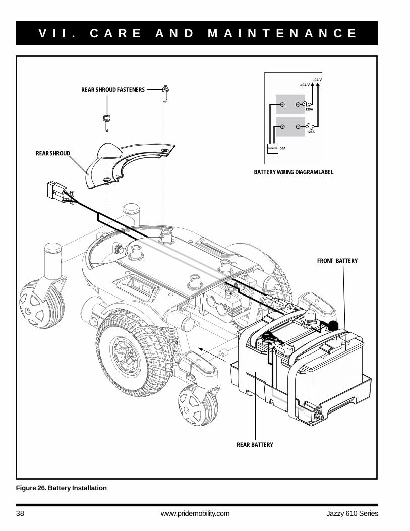
Battery ReplacementA battery wiring diagram is printed on a decal located on the front battery tray. See VI. “Batteries and Charging” forcorrect battery specifications.
WARNING! Do not replace battery when seat is occupied.
WARNING! Battery posts, terminals, and related accessories contain lead and lead compounds.Wear goggles and gloves when handling batteries and wash hands after handling.
WARNING! Power chair batteries are heavy. See specifications table. If you are unable to lift thatmuch weight, be sure to get help. Use proper lifting techniques and avoid lifting beyond yourcapacity.
WARNING! Do not mix or match new and old batteries. If you encounter a situation where onebattery needs to be replaced, then replace both batteries. Refer to the specifications table in thismanual and the manual supplied with the battery charger for recommended type and capacities.
38 www.pridemobility.com Jazzy 610 Series
BATTERY WIRING DIAGRAM LABEL
V I I . C A R E A N D M A I N T E N A N C E
Figure 26. Battery Installation
REAR SHROUD FASTENERS
REAR SHROUD
FRONT BATTERY
REAR BATTERY

Jazzy 610 Series www.pridemobility.com 39
V I I . C A R E A N D M A I N T E N A N C E
To replace the batteries:1. Turn off the power to the controller.2. Make sure that the power chair is in drive mode. See III. “Your Power Chair.”3. Loosen the rear shroud fasteners. See figure 26.4. Remove the rear shroud.5. Disconnect the battery harness from the rear battery.6. Remove the retaining pin and lift off the front cover using the foot platform bracket. See figure 17.7. Slide the battery tray forward.8. Disconnect the battery harness from the front battery.9. Unfasten the hook and loop straps from both batteries.10. Remove the batteries.11. Install new batteries.12. Fasten the hook and loop straps around both batteries.13. Connect the battery harness to the front battery according to the battery wiring diagram.
WARNING! Make sure you tighten the fasteners so that the connections are secure.
14. Slide the battery tray back into the power base.15. Connect the battery harness to the rear battery.16. Reinstall the front cover.17. Reinstall the rear shroud and tighten the fasteners.18. Charge the batteries. See VI. “Batteries and Charging.”
When to See Your Authorized Pride Provider for ServiceThe following symptoms could indicate a serious problem with your power chair. If necessary, contact your authorizedPride Provider. When calling, have the model number, serial number, nature of the problem, and the error code if available.! Motor noise! Frayed harnesses! Cracked or broken connectors! Uneven wear on any of the tires! Jerky motion! Pulling to one side! Bent or broken wheel assemblies! Does not power up! Powers up, but does not move
Corrective MaintenanceIf the battery condition meter does not light up when you turn on the power:! Check the harness connections. Make sure they are tight.! Check the circuit breaker. Reset it if necessary.! Check the battery connections.
If the above conditions prove normal, you can load test the batteries with a battery load tester. These testers are availableat automotive parts stores. Disconnect both batteries before load testing and follow the directions that come with the loadtester. If either one of the batteries fails the load test, replace both of them. If your power chair still does not power up,contact your authorized Pride Provider.

40 www.pridemobility.com Jazzy 610 Series
V I I I . W A R R A N T Y
LIFETIME LIMITED WARRANTYFor the lifetime of your power chair from the date of purchase, Pride will repair or replace at our option to the originalpurchaser, free of charge, any of the following parts found upon examination by an authorized representative of Pride to bedefective in material and/or workmanship:
Structural frame components, including:! Main Frame ! Fixed-position seat post
TWO-YEAR LIMITED WARRANTYFor two (2) years from the date of purchase, Pride will repair or replace at our option to the original purchaser, free ofcharge, any of the following parts found upon examination by an authorized representative of Pride to be defective inmaterial and/or workmanship:
Electronic components, including: Main frame assemblies, including:! Charger Assembly ! Anti-tip forks ! Caster forks! Controller ! Caster beam ! Metal seat framing! Joystick
Other components, including:! Foot riggings ! Electrical Harness ! Foot rigging mounting brackets
18-MONTH LIMITED WARRANTYFor eighteen (18) months from the date of purchase, Pride will repair or replace at our option to the original purchaser, freeof charge, any of the following parts found upon examination by an authorized representative of Pride to be defective inmaterial and/or workmanship:
! Motor/gearbox assembly ! Power seat actuator
ONE-YEAR LIMITED WARRANTYFor one (1) year from the date of purchase, Pride will repair or replace at our option to the original purchaser, free ofcharge, any of the following parts found upon examination by an authorized representative of Pride to be defective inmaterial and/or workmanship:
! Accessories ! Brakes (electronic function ONLY)
SIX-MONTH LIMITED WARRANTYFor six (6) months from the date of purchase, Pride will repair or replace at our option to the original purchaser, free ofcharge, any of the following parts found upon examination by an authorized representative of Pride to be defective inmaterial and/or workmanship:
! Bearings and bushings ! Plastic components, except body
The battery is covered by a separate six-month warranty, provided by the battery manufacturer. The batteries are notwarranted by Pride.

Jazzy 610 Series www.pridemobility.com 41
V I I I . W A R R A N T Y
RECONDITIONED UNITS WARRANTYAll reconditioned units are covered by a six-month warranty from Pride effective from the date of purchase.
WARRANTY EXCLUSIONSThis warranty does not extend to those items which may require replacement due to normal wear and tear.! ABS Plastic shrouds ! Motor brushes ! Upholstery and seating! Brake Pads ! Tires and tubes ! Fuses/Bulbs
! Circumstances beyond the control of Pride! Labor, service calls, shipping, and other charges incurred for repair of the product, unless specifically authorized, IN
ADVANCE, by Pride Mobility Products Corporation! Repairs and/or modifications made to any part without specific consent from Pride
Exclusions also include components with damage caused by:! Contamination! Abuse, misuse, accident, or negligence! Battery fluid spillage or leakage! Commercial use, or use other than normal! Improper operation, maintenance, or storage
NOTE: Gradual deterioration in performance because the battery has been left in a discharged state, left incold conditions for an extended period of time, or worn out through heavy use is not covered.
SERVICE CHECKS AND WARRANTY SERVICEWarranty service must be performed by an authorized Pride Provider. Do not return faulty parts to Pride without priorwritten authorization. All transportation costs and shipping damage incurred while submitting parts for repair or replacementare the responsibility of the purchaser.
Failure to follow the instructions, warnings, and notes in the owner’s manual and those located on your Pride product canresult in personal injury or product damage and will void Pride’s product warranty.
There is no other express warranty.
IMPLIED WARRANTIESImplied warranties, including those of merchantability and fitness for a particular purpose, are limited to one (1) year fromthe date of purchase and to the extent permitted by law. Any and all implied warranties are excluded. This is the exclusiveremedy. Liabilities for consequential damages under any and all warranties are excluded.
Some states do not allow limitations on how long an implied warranty lasts or do not allow the exclusion of limitationincidental or consequential damages. The above limitation or exclusion may not apply to you.
This warranty gives you specific rights, and you may also have other rights which vary from state to state.
Please fill out and return the product registration card to Pride. This will aid Pride in providing the best possible technicaland customer service.

42 www.pridemobility.com Jazzy 610 Series
N O T E S

Pride keeps a more detailed report on file at the factory.
Date Inspected
Inspector
Quality Control - Jazzy 610 Series
Inclusion of all Parts
Joystick Serial Number
Controller Serial Number
Left Motor Serial Number
Right Motor Serial Number
Fit and Finish
Performance
*INFMANU2897* Product Serial #