Jawaharlal Nehru Engineering College Laboratory Manual...
52
1 Jawaharlal Nehru Engineering College Laboratory Manual of Principle of Compiler Design For Final Year Students Dept: Computer Science & Engineering
-
Upload
vuongthuan -
Category
Documents
-
view
228 -
download
3
Transcript of Jawaharlal Nehru Engineering College Laboratory Manual...
1
Jawaharlal Nehru Engineering College
Laboratory Manual
of
Principle of Compiler Design
For
Final Year StudentsDept: Computer Science & Engineering

2
FOREWORD
It is my great pleasure to present this laboratory manual for final year
engineering students for the subject of Principle of compiler design keeping
in view the vast coverage required for understanding the concept of comiler
design
As a student, many of you may be wondering with some of the questions in
your mind regarding the subject and exactly what has been tried is to answer
through this manual.
As you may be aware that MGM has already been awarded with ISO 9000
certification and it is our endure to technically equip our students taking the
advantage of the procedural aspects of ISO 9000 Certification.
Faculty members are also advised that covering these aspects in initial
stage itself, will greatly relived them in future as much of the load will be taken
care by the enthusiasm energies of the students once they are conceptually clear.
Dr. S.D.Deshmukh,
Principal

3
LABORATORY MANUAL CONTENTS
This manual is intended for the Final year students of IT & CSE branches
in the subject of PCD. This manual typically contains practical/Lab Sessions
related PCD covering various aspects related the subject to enhanced
understanding. Strengthen knowledge of a procedural programming
language. Further develop your skills in software development using a
procedural language.
This course will also helpful for student for understanding design of a
compiler. We have made the efforts to cover various aspects of the subject
covering these labs encompass the regular materials as well as some
advanced experiments useful in real life applications. Programming aspects
will be complete in it to make it meaningful, elaborative understandable
concepts and conceptual visualization.
Students are advised to thoroughly go through this manual rather than only
topics mentioned in the syllabus, as practical aspects are the key to
understanding and conceptual visualization of theoretical aspects covered
in the books.
Dr.V.B.Musande Ms.Saroj S.Date,Mr. Mahendra K.UgaleHOD,CSE CSE Dept.

MGM’s
Jawaharlal Nehru Engineering College, Aurangabad
Department of Computer Science and Engineering
Vision of CSE Department:
To develop computer engineers with necessary analytical ability and human values who can
creatively design, implement a wide spectrum of computer systems for welfare of the society.
Mission of the CSE Department:
I. Preparing graduates to work on multidisciplinary platforms associated with their
professional position both independently and in a team environment.
II. Preparing graduates for higher education and research in computer science and engineering
enabling them to develop systems for society development.
Programme Educational Objectives:
Graduates will be able to
I. To analyze, design and provide optimal solution for Computer Science & Engineering and
multidisciplinary problems.
II. To pursue higher studies and research by applying knowledge of mathematics and
fundamentals of computer science.
III. To exhibit professionalism, communication skills and adapt to current trends by engaging
in lifelong learning.

Programme Outcomes (POs):
Engineering Graduates will be able to: 1. Engineering knowledge: Apply the knowledge of mathematics, science, engineering
fundamentals, and an engineering specialization to the solution of complex engineering
problems.
2. Problem analysis: Identify, formulate, review research literature, and analyze complex
engineering problems reaching substantiated conclusions using first principles of mathematics,
natural sciences, and engineering sciences.
3. Design/development of solutions: Design solutions for complex engineering problems and
design system components or processes that meet the specified needs with appropriate
consideration for the public health and safety, and the cultural, societal, and environmental
considerations.
4. Conduct investigations of complex problems: Use research-based knowledge and research
methods including design of experiments, analysis and interpretation of data, and synthesis of
the information to provide valid conclusions.
5. Modern tool usage: Create, select, and apply appropriate techniques, resources, and modern
engineering and IT tools including prediction and modeling to complex engineering activities
with an understanding of the limitations.
6. The engineer and society: Apply reasoning informed by the contextual knowledge to assess
societal, health, safety, legal and cultural issues and the consequent responsibilities relevant to
the professional engineering practice.
7. Environment and sustainability: Understand the impact of the professional engineering
solutions in societal and environmental contexts, and demonstrate the knowledge of, and need
for sustainable development.
8. Ethics: Apply ethical principles and commit to professional ethics and responsibilities and
norms of the engineering practice.
9. Individual and team work: Function effectively as an individual, and as a member or leader
in diverse teams, and in multidisciplinary settings.
10. Communication: Communicate effectively on complex engineering activities with the
engineering community and with society at large, such as, being able to comprehend and write
effective reports and design documentation, make effective presentations, and give and receive
clear instructions.
11. Project management and finance: Demonstrate knowledge and understanding of the
engineering and management principles and apply these to one’s own work, as a member and
leader in a team, to manage projects and in multidisciplinary environments.
12. Life-long learning: Recognize the need for, and have the preparation and ability to engage in
independent and life-long learning in the broadest context of technological change.

4
SUBJECT INDEX
1. Program to convert Non-deterministic finite automaton (NFA) to Deterministicfinite automaton (DFA).
2. Program to generate lexical tokens.
3. Study of LEX/FLEX tool and write LEX program to identify tokens: integernumbers, decimal numbers, identifiers, keywords, arithmetic operators, relationaloperators.
4. Program to implement LR parser.
5. Study of YACC tool.
6. Program to implement any one code optimization technique.
7. Implementation of any one method of Intermediate Code Generator.
8. Implementation of code generator.

5
DOs and DON’T DOs in Laboratory:
1. Make entry in the Log Book as soon as you enter the Laboratory.
2. All the students should sit according to their roll numbers starting from their left
to right.
3. All the students are supposed to enter the terminal number in the log book.
4. Do not change the terminal on which you are working.
5. All the students are expected to get at least the algorithm of the program/concept
to be implemented.
6. Strictly observe the instructions given by the teacher/Lab Instructor.
Instruction for Laboratory Teachers:
1. Submission related to whatever lab work has been completed should be doneduring the next lab session. The immediate arrangements for printouts related tosubmission on the day of practical assignments.
2. Students should be taught for taking the printouts under the observation of labteacher.
3. The promptness of submission should be encouraged by way of marking andevaluation patterns that will benefit the sincere students.

1. Lab Exercise
Aim: -Program to convert Non-deterministic finite automaton(NFA) toDeterministic finite automaton(DFA).
TOOLS: gcc/c compiler
STANDARD PROCEDURE:THEORY:FINITE AUTOMATA: Machine Model that Recognizes Regular LanguagesThe finite automata, (FA), machine M defined by the 5-tuple M = {Q, ∑, δ ,q0,
F}; where the
alphabet is: ∑ = {0,1};
Set of states is: Q = {s0, s1, s2};
Starting state is s0; the final state is: F = {s2};
Transitions δ are defined by the table below.δ 0 1 .s0 s0 s1s1 {s1, s2} s1s2 s2 Ø
M can also be represented by the transitiongraph:
01, 0 0
1 0s0 s1 s2
This figure (which corresponds to the transition table above) is a non-deterministic
finite automaton, NFA. The big circles represent states and the double circles
represent accepting or final states. The state with an unlabeled arrow coming from
its left is the starting state

NFA vs. DFA
Deterministic Finite Automaton (DFA)
• For every state there is exactly one outgoing edge per alphabet symbol.
• For each symbol in the alphabet there is a corresponding output and there is only
one.
Non-Deterministic Finite Automaton (NFA)
• At least one of the states has more than one outgoing edge for the same alphabet
symbol
(The transition function is not function, it is a relation.)
• There may be e transitions (transitions that occur without the presence of an
input symbol
from alphabet.)
ALGORITHM TO SIMULATE A DFA
Algorith1
Input: A string x ended by an EOF character and a DFA defined as a 5-tuple
with s0 as its initial state and F as its set of accepting states.
Output: A “YES” if the DFA accepts x or “NO” otherwise.
Method
Apply the “pseudo code” algorithm below to the input string x. The function
move(x, c) gives the state to which there is a transition from state s on input
character c. The function nextchar returns the next character of the input string x.
s = s0;
c = nextchar;while c =! EOFs = move(s, c);c=nextchar;endif s is in Fthen return”yes”else return “no”end

For e.g. convert Given NFA to its equivalent DFA
Equivalent DFA is given by-
[qo] [q0] [q1][q1] [q1q2] [q1]
* [q1q2] [q1q2] [q1]
CONCLUSIONS:With the help of given procedure and information about the Finite Automata,
we can write program to convert Non Deterministic Finite Automata toDeterministic Finite Automata.
q0 {q0} {q1}
q1 {q1, q2} {q1}
*q2 {q2} {Ø}

Aim:Program to generate lexical tokens.
STANDARD PROCEDURE:TOOLS: gcc/c compiler
THEORY:THE ROLE OF LEXICAL ANALYZER
The lexical analyzer is the first phase of a compiler. Its main task is to readthe input characters and produce as output a sequence of tokens that the parser usesfor syntax analysis. Upon receiving a “get next token” command from the parser,the lexical analyzer reads input characters until it can identify the next token.
Since the lexical analyzer is the part of the compiler that reads the sourcetext, it may also perform certain secondary tasks at the user interface. One suchtask is stripping out from the source program comments and white spaces inthe form of blank, tab, and new line characters. Another is correlating errormessages from the compiler with the source program.
Sometimes lexical analyzers are divided into a cascade of two phasesfirst called “scanning” and the second “lexical analysis”. The scanner is responsiblefor doing simple tasks, while the lexical analyzer proper does the more complexoperations.

Algorithm:
1. Declare an array of characters, as buffer to store the tokens ,that is,’lexbuffer’;
2. Get token from user put it into character type of variable, say ‘c’.
3. If ‘c’ is blank then do nothing.
4. If ‘c’ is new line character line=line+1.
5. If ‘c’ is digit, set token_val ,the value assigned for a digit and return ‘NUMBER’.
6. If ‘c’ is proper token then assign the token value.
Print the complete table with
a. Token entered by the user
b. Associated token value.
Output:
Enter the Statement
If(a= =1) then b++;
Token Code Value
--------------------------------
If 1 -( 5 1A 8 Pointer to Symbol
table= = 6 11 9 Pointer to literal
table) 5 2then 2 -B 8 Pointer to literal
table++ 6 2; 7 1
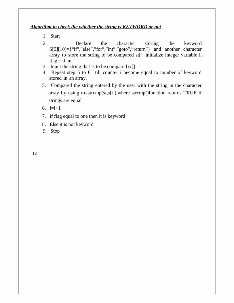
Algorithm to check the whether the string is KETWORD or not
1. Start
2. Declare the character storing the keywordS[5][10]={“if”,”else”,”for”,”int”,”goto”,”return”} and another characterarray to store the string to be compared st[], initialize integer variable l,flag = 0 ,m
3. Input the string that is to be compared st[]4. Repeat step 5 to 6 till counter i become equal to number of keyword
stored in an array.
5. Compared the string entered by the user with the string in the character
array by using m=strcmp(st,s[i]),where strcmp()function returns TRUE if
strings are equal
6. i=i+1
7. if flag equal to one then it is keyword
8. Else it is not keyword9. Stop
13

Output:
Enter the string : return
It is KEYWORD
Enter the string : hello
It is not KEYWORD
Algorithm to find whether the string is CONSTANT or not
1. Start
2. Declare the character array str[] and initialize integer variable len , a= 0.
3. Input the string from user
4. Find the length of the string
5. Repeat step 6 to 7 till a<len
6. If str[a] is numeric character then a++
7. Else it is not constant and break from the loop and goto step 9.
8. if a = = len then print that entered string is constant
9. else it is not a constant
10. Stop.
Output:
Input a string : 24
It is a CONSTANT
Input a string : a34
It is a NOT CONSTANT
Conclusion:
With the help of given procedure and information about the Lexical Analyzer Phasewe can write program to perform simulation of FA for implementation of Lexicalanalyzer phase.

3.Lab Exercise
Aim: Study of LEX/FLEX tool and write LEX program to identify tokens:integer numbers, decimal numbers, identifiers, keywords, arithmeticoperators, relational operators.
STANDARD PROCEDURE:
TOOLS: Flex ToolOperating System: Linux
THEORY:Lex is officially known as a "Lexical Analyzer". It’s main job is to break
up an input stream into more into meaningful units, or tokens. For example,
consider breaking a text file up into individual words.
More pragmatically, Lex is a tool for automatically generating a lexer ( also
known as scanner) starting from a lex specification (*.l file 2 ).
The skeleton of a lex specification file is given in Figure 3.
The rules section is composed of tuples of the form <pattern, action>. As it can be
seen from the following examples, are specified by regular expressions.
Example
<pattern> <action to take when matched> [A-Za-z]+ printf("this is a word") ;
<pattern> <action to take when matched> [0-9]+ printf("this is a number") ;
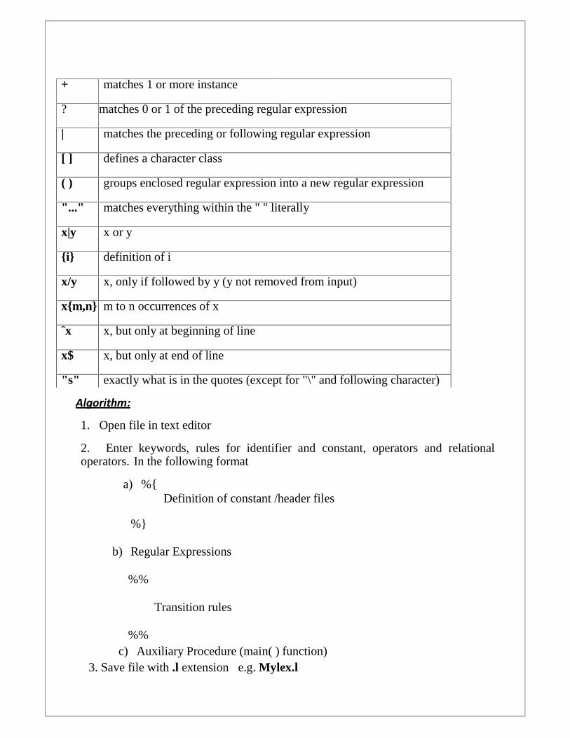
+ matches 1 or more instance
? matches 0 or 1 of the preceding regular expression
| matches the preceding or following regular expression
[ ] defines a character class
( ) groups enclosed regular expression into a new regular expression
"..." matches everything within the " " literally
x|y x or y
{i} definition of i
x/y x, only if followed by y (y not removed from input)
x{m,n} m to n occurrences of x
ˆx x, but only at beginning of line
x$ x, but only at end of line
"s" exactly what is in the quotes (except for "\" and following character)
Algorithm:
1. Open file in text editor
2. Enter keywords, rules for identifier and constant, operators and relationaloperators. In the following format
a) %{Definition of constant /header files
%}
b) Regular Expressions
%%
Transition rules
%%c) Auxiliary Procedure (main( ) function)
3. Save file with .l extension e.g. Mylex.l

4. Call lex tool on the terminal e.g. [root@localhost]# lex Mylex.l This lex toolwill convert “.l” file into “.c” language code file i.e. lex.yy.c
5. Compile the fi le lex.yy.c e.g. gcc lex.yy.c .After compiling the filelex.yy.c, this will create the output file a.out
6. Run the file a.out e.g. ./a.out
7. Give input on the terminal to the a.out file upon processing output will bedisplayed.
Example:
%{#include <stdio.h>
#include <ctype.h>%}
%%id[a-z0-9]+digit[0-9]
%%int main( )
{If|then|else|begin|end {“Keyword is:%s”,yytext);{id} {“identifier is :%s”,yytext);{digit}+ {constant is :%s,yytext);. {“invalid token”};
yylex();
Output:
For lexical analyzer
[root@localhost]# lex Mylex.l
[root@localhost]# gcc lex.yy.c
[root@localhost]# ./a.out123
Constant is 123
a
identifier is a

Conclusion:
With the help of given procedure and information about the Lex Tool,we can writelex program to identify different tokens.

4. Lab Exercise
Aim: Program to implement LR parser.
STANDARD PROCEDURE:TOOLS:Operating System:
THEORY:
LR Parser:LR parsing is a bottom up syntax analysis technique that can be applied to a largeclass of context free grammars. L is for left –to –right scanning of the input and Rfor constructing rightmost derivation in reverse.
General Framework:
Let x1x2 x3… … … xk be the string to be parsed by LR parsing method.
A configuration of an LR parser is a pair whose first component is the stack andwhose secondcomponent is the unexpended part of the input string:
s0Y1s1Y2si+1… … Yjsi+k xp… … xk
A B
part which is already part of the input string.considered for parsing.

0……… |Yjsi+k xpsi+k*|xp+1… … xk
Reduce:[s0………..si+gA] xp… … xk
Reduce A α, | α | = NPop 2*| N | elements including statesPush APut a state s[s0………..si+gAs] xp… … xk
Example:Consider the following grammar
1. S’ S2. S aABe3. A Abc4. A b5. B d
STACK
B
A
State from the table
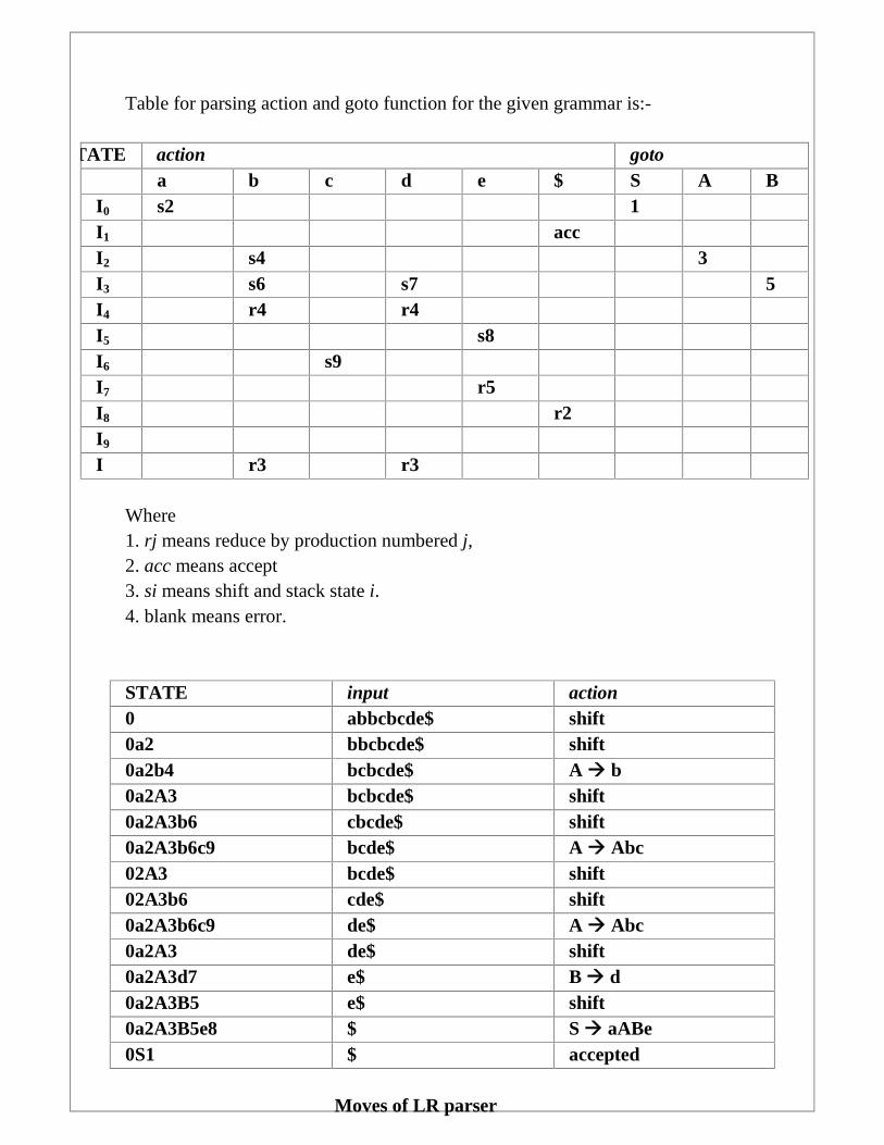
Table for parsing action and goto function for the given grammar is:-
STATE action gotoa b c d e $ S A B
I0 s2 1I1 accI2 s4 3I3 s6 s7 5I4 r4 r4I5 s8I6 s9I7 r5I8 r2I9
I r3 r3
Where1. rj means reduce by production numbered j,2. acc means accept3. si means shift and stack state i.4. blank means error.
STATE input action0 abbcbcde$ shift0a2 bbcbcde$ shift0a2b4 bcbcde$ A b0a2A3 bcbcde$ shift0a2A3b6 cbcde$ shift0a2A3b6c9 bcde$ A Abc02A3 bcde$ shift02A3b6 cde$ shift0a2A3b6c9 de$ A Abc0a2A3 de$ shift0a2A3d7 e$ B d0a2A3B5 e$ shift0a2A3B5e8 $ S aABe0S1 $ accepted
Moves of LR parser

Forming the Parsing table:1. Item:Item of a grammar G is a production of G with a dot at some position of the rightside.The production A XYZ has the following four itemsA .XYZA X.YZZ XY.ZA XYZ.
2. Item closure:If A X.YZ belongs to Is
Y βThen add Y .β in Is
Item closure for the above example
I0 = {[S’ .S], [S .aABe]}I1 = {S’ S.}I2 = {S a.ABe, A .Abc, A .b}I3 = {S aA.Be, A A.bc, B .d}I4 = {A b.}I5 = {S aAB.e}I6 = {A Ab.c}I7 = {B d.}I8 = {S aABe.}I9 = {A Abc.}
Constructing the GOTO graph from the LR(0) Items ABOVE derived.1. Enlist all the collection of Items: C (I0, I1,…..)2. Put all the transitions in the between the Items in he GOTO graph.
Rules for putting the label on the transitionIf there is a transition from,
A->α . Xβ to A-> αX . βthen, the transition in the GOTO Graph is labeled XIf there is a transition
A-> α . Bβ to B-> .γthen, the transition is labeled ε, and since we take ε-closure of all Items, theseproductions lie in the same item as that of A->α . Bβ to A-> αB . β.So, the GOTO Graph of the given grammar is produced follows.

The GOTO Graph for the given grammar.From the GOTO Graph we now start filling the Parsing table for the SLR (simpleLR) parser, Which contains State i as the row index and action & goto as thevertical column index.The Rules for filling the action entries in the table are:1.If [ A-> α .a β ] is in Ii and goto ( Ii , a ) = Ij, then set action [i ,a] to “shift j “.Herea must be a terminal.2. If [A-> α .] is in Ii, then set action[i , a ] to “reduce A -> α “ for all a in FOLLOW(A); here A may not be in S’.3. If [ S’-> S.] is in Ii , then set action [I, $] to accept.
If any conflicting actions are generated by the given rules, then we say the grammaris not in SLR or LR (0) and we fail to produce a parser.
S’-> .S
S->.aABe
I0
S’ -> S.
I1
S-> a.Abe
A->.Abc
A->.b
I2
S->aA.Be
A->A.bc
B->.d
I3
A -> b.
I4
S->aAB.e
I5
S->aABe.
I8
B->d.
I7
A->Abc.
I9
A->Ab.c
I6
a
$
b
A
B
e
b
c
d

We then fill the goto entries.The goto transitions for the state i are constructed for all the non-terminals Ausing the Rule:If goto( Ii, A ) = Ij , then goto [i , A ] = j .
Note : goto (Ii, A) is an entry in graph, whereas goto[i, A] is the corresponding
entry in parsing table .
Also the initial state of the parser is one constructed from the set of items containing
[S’-> .S]
So, the Parsing table for the grammar comes out to be.
Using this we go ahead with the parsing action.
A grammar having a SLR parsing table is said to be a SLR grammar, and it has a
lookahead of 1.
We have a noteworthy point in the grammar we just now used. We have the starting
production as
S’-> S and then S had its own set of productions. Intuitively, we see that, there arises
no need for the extra production rule S’->S and this rule might be treated as a
dummy rule. We could always do away with S’ and have S as the start state.
However, closer inspection brings to light on the fact that, while staring the parsing,
we may not have any problem, but on making reduction to start state (remember we
are parsing bottom up!), we might just end up having reduce conflicts. So, a need to
have a ‘one-level’ higher hierarchy is necessitated and is provided by the rule S’-> S,
whenever the start state S, has multiple productions.
We now look into the problems underlying the SLR grammar, and move onto
greener pastures where we could possibly cope up with these problems.

Problems with SLR parser:
The SLR parser discussed in the earlier class has certain flaws.
1. A state may include a final item (one in which the position marker is at the
end) and a non- final item. This is called a shift-reduce conflict
2. A state may include two different final items. This is called a reduce-reduce
conflict
• Can we have reduce-reduce conflicts in unambiguous grammars?
• Can we have a shift-shift conflict ?
However SLR reduces only when the next token is in Follow of the left-hand side
of the production. Such choices may help to resolve reduce-reduce
conflicts.However, still similar conflicts exist:
->Shift-reduce conflicts include the case in which
Follow of the final lhs of the final item overlaps with first of the remainder
-> Reduce-reduce conflicts include the case Follow of both left-hand-
sides overlap.
Conclusion:With the help of given procedure and information about the LR Parse,we can writeprogram for implementation of LR parser.
5. Lab Exercise
Aim :Study of YACC tool.
STANDARD PROCEDURE:
TOOLS: yaccOperating System: Linux
THEORY:YACC stands for Yet Another Compiler Compiler. Its GNU version is calledBison. YACC translates any grammar of a language into a parser for thatlanguage. Grammars for YACC are described using a variant of Backus NaurForm (BNF). A BNF grammar can be used to express Context-free languages. Byconvention, a YACC file has the suffix .y.
Structure of a yacc fileA yacc file looks much like a lex file:
...definitions...
%%
...rules...
%%
...code...
Definitions All code between %{ and %} are copied to the beginning of theresulting C file. Rules A number of combinations of pattern and action: if theaction is more than a single command it needs to be in braces.Code This can be very elaborate, but the main ingredient is the call toyylex, the lexical analyzer. If the code segment is left out, a default main isused which only call yylex.

Yacc File Structure
%{
#include <stdio.h>
int yylex(void);
void yyerror(char *);
%}
%token INTEGER
%%
program:
program expr ’\n’ { printf("%d\n",$2);}
|
;
expr:
INTEGER { $$ = $1; }
| expr ’+’ expr { $$ = $1 + $3; }
| expr ’-’ expr { $$ = $1 - $3; }
;
%%
int main()
{
yyparse();
}

void yyerror(char *s)
{
printf("%s",s);
}
Algorithm:
1. Open file in text editor
2. Specify grammar rules and associated action in thefollowing format a. %{
Statements (Include statement optional)
%}
b. Lexical tokens, grammar, precedence and associated information.
%%
Grammar, rules and action
%%
c. Auxiliary Procedure (main( ) function)
3. Save file with .l extension e.g. Mylex.l
4. Call lex tool on the terminal e.g. [root@localhost]# lex Mylex.l This lex toolwill convert
“.l” file into “.c” language code file i.e. lex.yy.c
5. Compile the file lex.yy.c e.g. gcc lex.yy.c .After compiling the filelex.yy.c, this will create the output file a.out
7. Run the file a.out e.g. ./a.out
8. Give input on the terminal to the a.out file upon processing output will bedisplayed

<parse.l>%{
#include<stdio.h>
#include "y.tab.h"
%}
%%
[0-9]+ {yylval.dval=atof(yytext);
return DIGIT;
}
\n|. return yytext[0];
%%
<parser.y>%{
#include<stdio.h>
%}
%union
{
double dval;
}
%token <dval> DIGIT
%type <dval> expr
%type <dval> term
%type <dval> factor
%%line:expr’\n’ printf(“%g\n”,$1);

expr: expr '+' term {$$=$1 + $3 ;}
| term
;
term: term '*' factor {$$=$1 * $3 ;}
| factor
;
factor: '(' expr ')' {$$=$2 ;}
| DIGIT
;
%%
int main()
{
yyparse();
}
yyerror(char *s)
{
printf("%s",s);
}
Output:
#lex parser.l
#yacc –d parser.y
#cc lex.yy.c y.tab.c –ll –lm
#./a.out
2+35.0000
Conclusion:With the help of given information and procedure we can write Yacc program
for construction of compiler.

6. Lab Exercise
Aim: Program to implement any one code optimization technique.
STANDARD PROCEDURE:
Programming Language: COperating System: Linux or Windows
Theory:
To create an efficient target language program, a programmer needs
more than an optimizing compiler. In this section, we review the options available
to a programmer and a compiler for creating efficient target programs. We mention
of code-improving transformations that a programmer and a compiler writer can be
expected to use it improve the performance of a program.
Criteria for Code-Improving Transformations
The best program transformations are those that yield the most benefit for the
least effort. The transformations provided by an optimizing compiler should
have several properties.
First, a transformation must preserve the meaning of programs. That is, an
“optimization” must not change the output produced by a program for a given
input, or cause an error, such as division by zero, that was not present in the
original version of the source program.
Second, a transformation must, on the average, speed up programs bymeasurable amount.
Third, a transformation must be worth the effort. It does not make sense for a
compiler writer to expend the intellectual effort to implement a code-improving
transformation
Getting Better Performance
Dramatic improvements in the running time of a program –such as cutting therunning time from a few hours to few seconds-are usually obtained by improvingthe program at all levels.

Fig.Places for improvements by the user and the compiler
1 Eliminating Loop Invariant Computations
To eliminate loop invariant computations, we first identify the invariant
computations and then move them outside loop if the move does not lead to a
change in the program's meaning. Identification of loop invariant computation
requires the detection of loops in the program. Whether a loop exists in the
program or not depends on the program's control flow, therefore, requiring a
control flow analysis. For loop detection, a graphical representation, called a
"program flow graph," shows how the control is flowing in the program and how
the control is being used. To obtain such a graph, we must partition the
intermediate code into basic blocks. This requires identifying leader statements,
which are defined as follows:
1. The first statement is a leader statement.
2. The target of a conditional or unconditional goto is a leader.
3. A statement that immediately follows a conditional goto is a leader.
A basic block is a sequence of three-address statements that can be entered
only at the beginning, and control ends after the execution of the last statement,
without a halt or any possibility of branching, except at the end.

2 Algorithm to Partition Three-Address Code into Basic Blocks
To partition three-address code into basic blocks, we must identify the leader
statements in the three-address code and then include all the statements, starting
from a leader, and up to, but not including, the next leader. The basic blocks into
which the three-address code is partitioned constitute the nodes or vertices of the
program flow graph. The edges in the flow graph are decided as follows. If B1 and
B2 are the two blocks, then add an edge from B1 to B2 in the program flow graph,
if the block B2 follows B1 in an execution sequence. The block B2 follows B1 in
an execution sequence if and only if:
1. The first statement of block B2 immediately follows the last statement of block
B1 in the three-address code, and the last statement of block B1 is not an
unconditional goto statement.
2. The last statement of block B1 is either a conditional or unconditional goto
statement, and the first statement of block B2 is the target of the last statement of
block B1.
For example, consider the following program fragment:
Fact(x)
{
int f = 1;
for(i = 2; i<=x; i++)
48
f = f*i;
return(f);
}
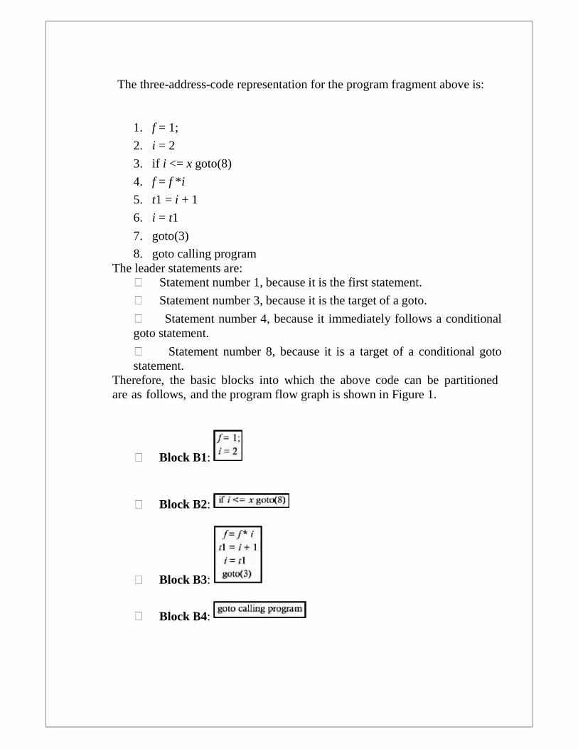
The three-address-code representation for the program fragment above is:
1. f = 1;
2. i = 2
3. if i <= x goto(8)
4. f = f *i
5. t1 = i + 1
6. i = t1
7. goto(3)
8. goto calling programThe leader statements are:
Statement number 1, because it is the first statement.
Statement number 3, because it is the target of a goto.
Statement number 4, because it immediately follows a conditionalgoto statement.
Statement number 8, because it is a target of a conditional gotostatement.
Therefore, the basic blocks into which the above code can be partitionedare as follows, and the program flow graph is shown in Figure 1.
Block B1:
Block B2:
Block B3:
Block B4:

Fig-Program Flow Graph
A loop is a cycle in the flow graph that satisfies two properties:
1. It should have a single entry node or header, so that it will be possible tomove all of the loop invariant computations to a unique place, called a"preheader," which is a block/node placed outside the loop, just in front ofthe header.
2. It should be strongly connected; that is, it should be possible to go fromany node of the loop to any other node while staying within the loop. This isrequired until at least some of the loops get executed repeatedly.
If the flow graph contains one or more back edges, then only one or more loops/xcycles exist in the program. Therefore, we must identify any back edges in theflow graph.
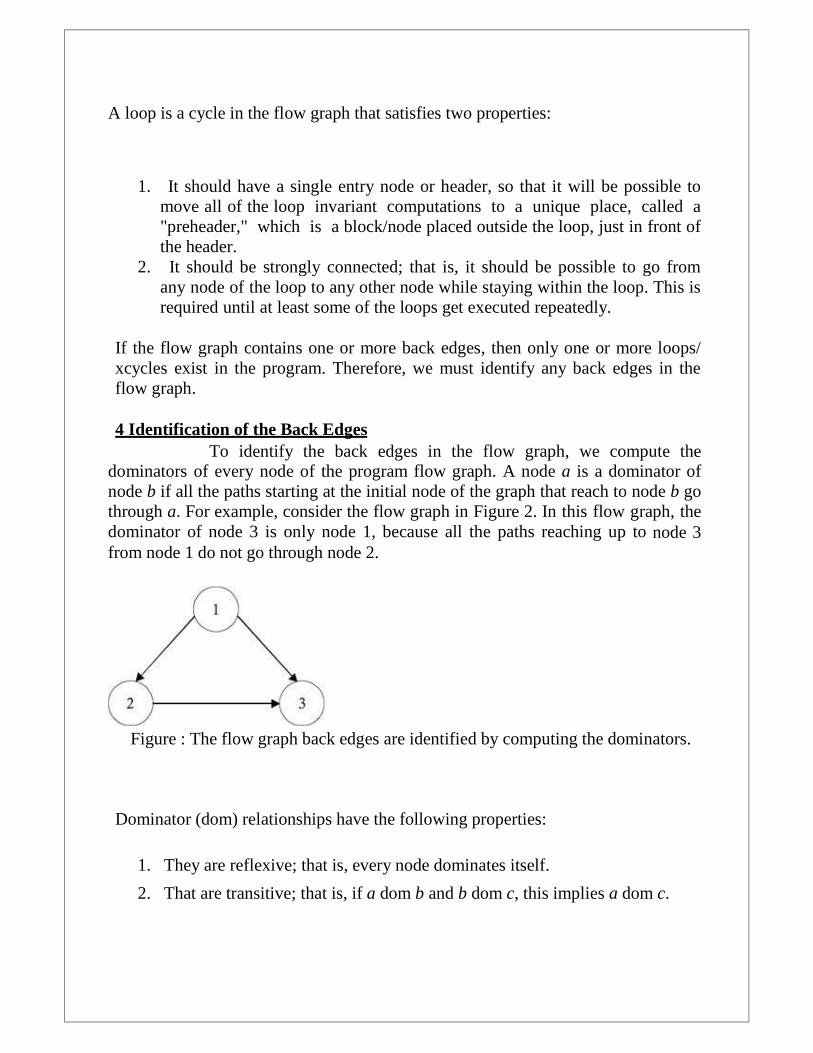
4 Identification of the Back EdgesTo identify the back edges in the flow graph, we compute the
dominators of every node of the program flow graph. A node a is a dominator ofnode b if all the paths starting at the initial node of the graph that reach to node b gothrough a. For example, consider the flow graph in Figure 2. In this flow graph, thedominator of node 3 is only node 1, because all the paths reaching up to node 3from node 1 do not go through node 2.
Figure : The flow graph back edges are identified by computing the dominators.
Dominator (dom) relationships have the following properties:
1. They are reflexive; that is, every node dominates itself.
2. That are transitive; that is, if a dom b and b dom c, this implies a dom c.

5 Reducible Flow Graphs
Several code-optimization transformations are easy to perform on reducible flowgraphs. A flow graph G is reducible if and only if we can partition the edges intotwo disjointed groups, forward edges and back edges, with the following twoproperties:
1. The forward edges form an acyclic graph in which every node can bereached from the initial node G.
2. The back edges consist only of edges whose heads dominate their tails.
For example, consider the flow graph shown in Figure 3. This flow graph has noback edges, because no edge's head dominates the tail of that edge. Hence, it couldhave been a reducible graph if the entire graph had been acyclic. But that is not thecase. Therefore, it is not a reducible flow graph.
Figure :A flow graph with no back edges
After identifying the back edges, if any, the natural loop of every back edge mustbe identified. The natural loop of a back edge a → b is the set of all thosenodes that can reach a without going through b, including node b itself.
Therefore, to find a natural loop of the back edge n →d, we start with node n andadd all the predecessors of node n to the loop. Then we add the predecessors of thenodes that were just added to the loop; and we continue this process until we reachnode d. These nodes plus node d constitute the set of all those nodes that can reachnode n without going through node d. This is the natural loop of the edge n → d.Therefore, the algorithm for detecting the natural loop of a back edge is:
Input : back edge n→ d.
Output: set loop, which is a set of nodes forming the natural loop of the back edgen → d.

52
main(){
loop = { d } / * Initialize by adding node d to the set loop*/insert(n); /* call a procedure insert with the node n */
}procedure insert(m){
if m is not in the loop then{loop = loop ∪ { m }
for every predecessor p of m doinsert(p);
}}
For example in the flow graph shown in Figure 1, the back edges are edge B3→ B2, and the loop is comprised of the blocks B2 and B3.
After the natural loops of the back edges are identified, the next task is to identifythe loop invariant computations. The three-address statement x = y op z, whichexists in the basic block B (a part of the loop), is a loop invariant statement if allpossible definitions of b and c that reach upto this statement are outside the loop,or if b and c are constants, because then the calculation b op c will be the sameeach time the statement is encountered in the loop. Hence, to decide whether thestatement x = b op c is loop invariant or not, we must compute the u−d chaininginformation. The u−d chaining information is computed by doing a global dataflow analysis of the flow graph. All of the definitions that are capable of reachingto a point immediately before the start of the basic block are computed, and we callthe set of all such definitions for a block B the IN(B). The set of all the definitionscapable of reaching to a point immediately after the last statement of block B willbe called OUT(B). We compute both IN(B) and OUT(B) for every block B,GEN(B) and KILL(B), which are defined as:
GEN(B): The set of all the definitions generated in block B.KILL(B): The set of all the definitions outside block B that define the samevariables as are defined in block B.
Consider the flow graph in Figure 4.The GEN and KILL sets for the basic blocksare as shown in Table 1.

53
Table 1: GEN and KILL sets for Figure 4 Flow Graph
Block GEN KILL
B1 {1,2} {6,10,11}B2 {3,4} {5,8}
B3 {5} {4,8}B4 {6,7} {2,9,11}
B5 {8,9} {4,5,7}
B6 {10,11} {1,2,6}
Figure 4: Flow graph with GEN and KILL block sets.
IN(B) and OUT(B) are defined by the following set of equations, which are
called "data flow equations":
The next step, therefore, is to solve these equations. If there are n nodes, there willbe 2n equations in 2n unknowns. The solution to these equations is not generally

54
unique. This is because we may have a situation like that shown in Figure 5, wherea block B is a predecessor of itself.
Figure Nonunique solution to a data flow equation, where B is a predecessor ofitself.
If there is a solution to the data flow equations for block B, and if the solution isIN(B) = IN0 and OUT(B) = OUT0, then IN0 ∪ {d} and OUT0 ∪ {d}, where d isany definition not in IN0. OUT0 and KILL(B) also satisfy the equations, because ifwe take OUT0 ∪ {d} as the value of OUT(B), since B is one of the predecessorsof itself according to IN(B) = ∪ OUT(P), d gets added to IN(B), because d is notin the KILL(B). Hence, we get IN(B) = IN0 ∪ {d}. And according to OUT(B) =IN(B) − KILL(B) GEN(B), OUT(B) = OUT0 ∪ {d} gets satisfied. Therefore,IN0, OUT0 is one of the solutions, whereas IN0 ∪ {d}, OUT0 ∪ {d} isanother solution to the equations—no unique solution. What we are interested in isfinding smallest solution, that is, the smallest IN(B) and OUT(B) for every block B,which consists of values that are in all solutions.
The algorithm for computing the smallest IN(B) and OUT(B) is as follows:
1. For each block B do
2. {
IN(B)= φOUT(B)= GEN(B)
}
3. flag = true
4. while (flag) do

55
5.{
flag = false
for each block B do
{
INnew(B) = Φ
56
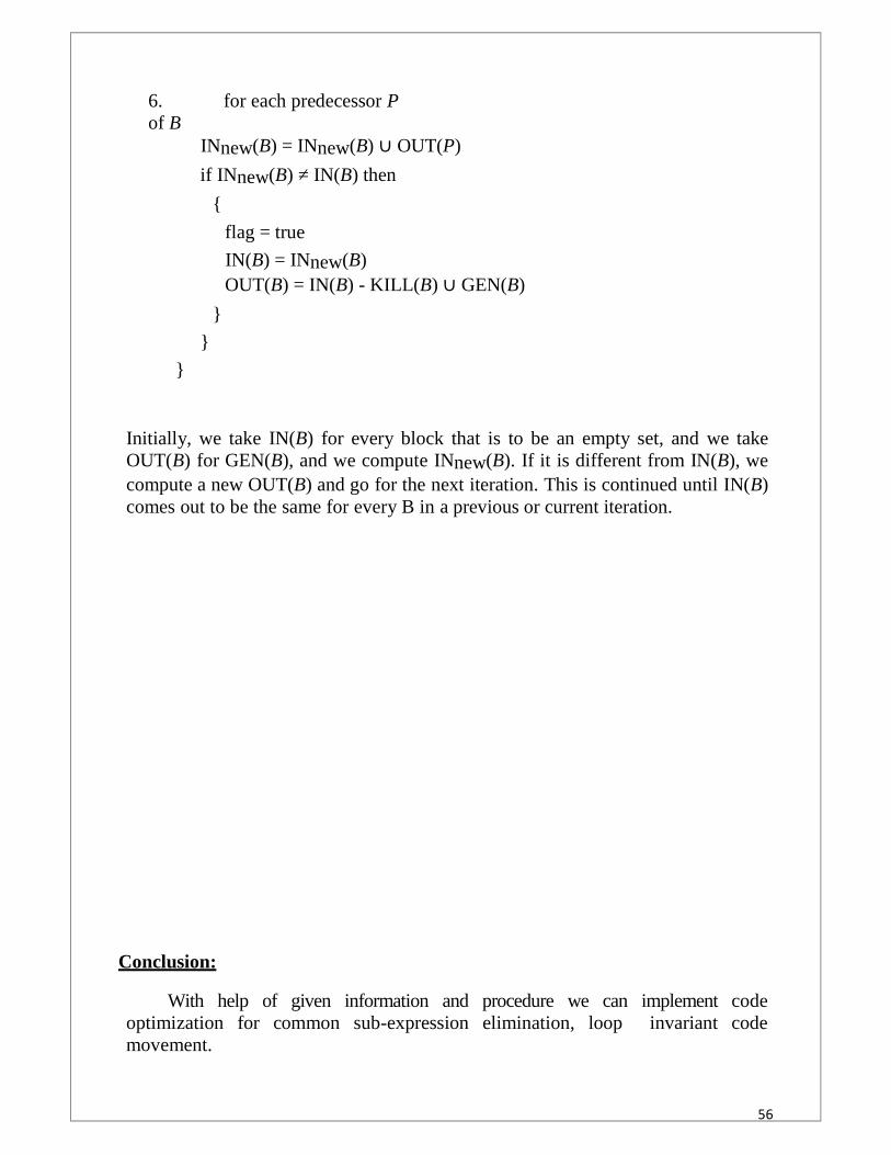
6. for each predecessor Pof B
INnew(B) = INnew(B) ∪ OUT(P)
if INnew(B) ≠ IN(B) then
{
flag = true
IN(B) = INnew(B)OUT(B) = IN(B) - KILL(B) ∪ GEN(B)
}
}
}
Initially, we take IN(B) for every block that is to be an empty set, and we takeOUT(B) for GEN(B), and we compute INnew(B). If it is different from IN(B), wecompute a new OUT(B) and go for the next iteration. This is continued until IN(B)comes out to be the same for every B in a previous or current iteration.
Conclusion:
With help of given information and procedure we can implement codeoptimization for common sub-expression elimination, loop invariant codemovement.

57
7. Lab Exercise
Aim: Implementation of any one method of Intermediate Code Generator.STANDARD PROCEDURE:
Programming language-COperating System: Linux or Windows
THEORY:Program to convert Infix expression to Postfix
While translating a source program into a functionally equivalent object coderepresentation, aparser may first generate an intermediate representation. This makes retargeting ofthe code
possible and allows some optimizations to be carried out that would otherwise notbe possible.
The following are commonly used intermediate representations:
1. Postfix notation
2. Syntax tree
3. Three-address code
Postfix Notation
In postfix notation, the operator follows the operand. For example, in the expression(a − b) * (c+ d) + (a − b), the postfix representation is:
Syntax Tree
The syntax tree is nothing more than a condensed form of the parse tree. Theoperator and
keyword nodes of the parse tree (Figure 1) are moved to their parent, and a chain ofsingle
productions is replaced by single link (Figure ).
58
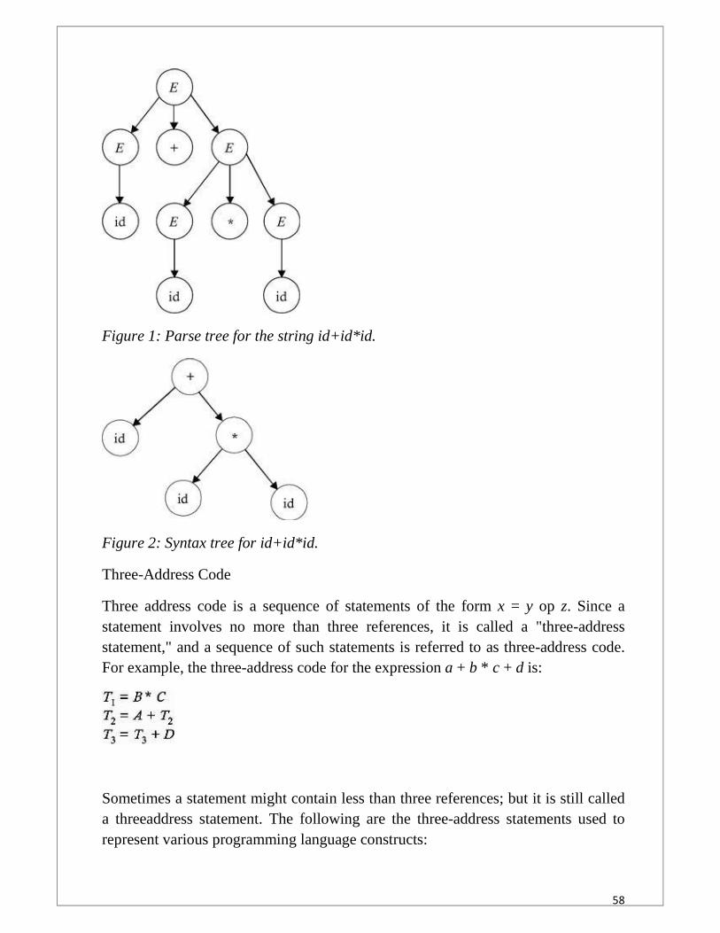
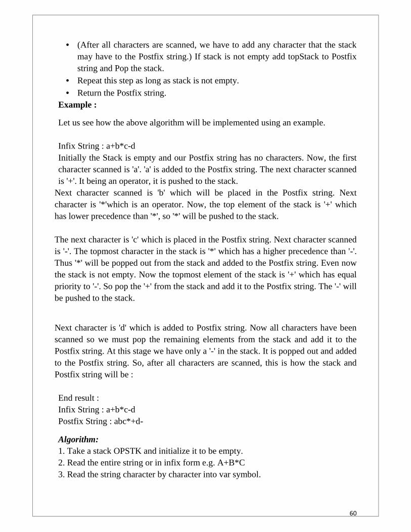
Figure 1: Parse tree for the string id+id*id.
Figure 2: Syntax tree for id+id*id.
Three-Address Code
Three address code is a sequence of statements of the form x = y op z. Since astatement involves no more than three references, it is called a "three-addressstatement," and a sequence of such statements is referred to as three-address code.For example, the three-address code for the expression a + b * c + d is:
Sometimes a statement might contain less than three references; but it is still calleda threeaddress statement. The following are the three-address statements used torepresent various programming language constructs:

59
Used for representing arithmetic expressions:
Used for representing Boolean expressions:
Used for representing array references and dereferencing operations:
Used for representing a procedure call:
Infix Expression :Any expression in the standard form like "2*3-4/5" is an Infix(Inorder) expression.Postfix Expression :The Postfix(Postorder) form of the above expression is "23*45/-".Infix to Postfix Conversion :In normal algebra we use the infix notation like a+b*c. The corresponding postfixnotation is abc*+.The algorithm for the conversion is as follows :
Scan the Infix string from left to right. Initialise an empty stack. If the scannned character is an operand, add it to the Postfix string. If the
scanned character is an operator and if the stack is empty Push the character tostack.
If the scanned character is an Operand and the stack is not empty, compare theprecedence of the character with the element on top of the stack (topStack). Iftop Stack has higher precedence over the scanned character Pop the stack elsePush the scanned character to stack. Repeat this step as long as stack is notempty and topStack has precedence over the character.
Repeat this step till all the characters are scanned.
60
(After all characters are scanned, we have to add any character that the stackmay have to the Postfix string.) If stack is not empty add topStack to Postfixstring and Pop the stack.
Repeat this step as long as stack is not empty. Return the Postfix string.
Example :
Let us see how the above algorithm will be implemented using an example.
Infix String : a+b*c-dInitially the Stack is empty and our Postfix string has no characters. Now, the firstcharacter scanned is 'a'. 'a' is added to the Postfix string. The next character scannedis '+'. It being an operator, it is pushed to the stack.
Next character scanned is 'b' which will be placed in the Postfix string. Nextcharacter is '*'which is an operator. Now, the top element of the stack is '+' whichhas lower precedence than '*', so '*' will be pushed to the stack.
The next character is 'c' which is placed in the Postfix string. Next character scannedis '-'. The topmost character in the stack is '*' which has a higher precedence than '-'.Thus '*' will be popped out from the stack and added to the Postfix string. Even nowthe stack is not empty. Now the topmost element of the stack is '+' which has equalpriority to '-'. So pop the '+' from the stack and add it to the Postfix string. The '-' willbe pushed to the stack.
Next character is 'd' which is added to Postfix string. Now all characters have beenscanned so we must pop the remaining elements from the stack and add it to thePostfix string. At this stage we have only a '-' in the stack. It is popped out and addedto the Postfix string. So, after all characters are scanned, this is how the stack andPostfix string will be :
End result :Infix String : a+b*c-dPostfix String : abc*+d-
Algorithm:1. Take a stack OPSTK and initialize it to be empty.2. Read the entire string or in infix form e.g. A+B*C3. Read the string character by character into var symbol.

61
i)If symbol is an operand Add it to the postfix string.ii)if stack OPSTK is not empty and precedence of top of stack symbol is greaterthan recently read character symbol then pop OPSTK .topsymbol=pop(OPSTK) Add this popped topsymbol to the postfix stringiii) Repeat step iii. Till stack is not empty precedence of top of stack symbol isgreater than recently read character symbol.iv) push symbol onto OPSTK.4. Output any remaining operators.Pop OPSTK till it is not empty and ad top symbol to postfix string .Output:------------------------------------------Enter the Infix Notation : (A+B)*CPostfix Notation is: AB+C*
Conclusion:
With help of given information and procedure we can implement one of theintermediate code like infix to postfix.
62
8. Lab Exercise
Aim: Implementation of code generator.
STANDARD PROCEDURE:
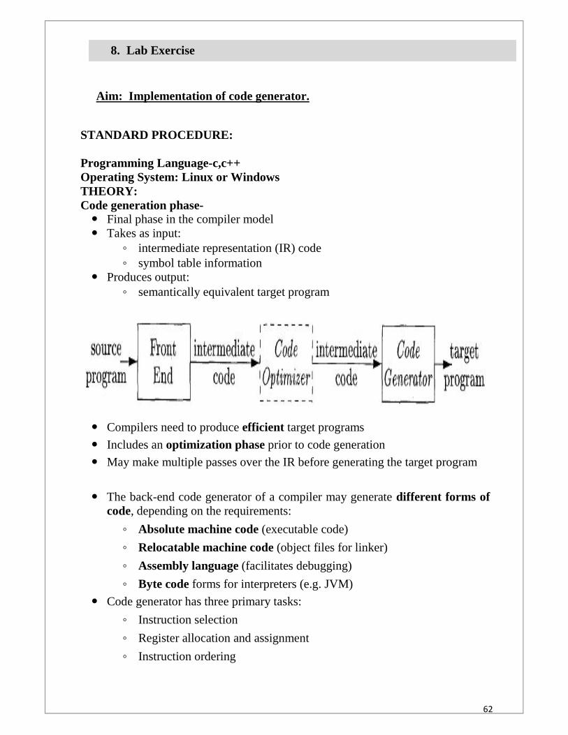
Programming Language-c,c++Operating System: Linux or WindowsTHEORY:Code generation phase- Final phase in the compiler model Takes as input:
◦ intermediate representation (IR) code◦ symbol table information
Produces output:◦ semantically equivalent target program
Compilers need to produce efficient target programs
Includes an optimization phase prior to code generation
May make multiple passes over the IR before generating the target program
The back-end code generator of a compiler may generate different forms ofcode, depending on the requirements:
◦ Absolute machine code (executable code)
◦ Relocatable machine code (object files for linker)
◦ Assembly language (facilitates debugging)
◦ Byte code forms for interpreters (e.g. JVM)
Code generator has three primary tasks:
◦ Instruction selection
◦ Register allocation and assignment
◦ Instruction ordering

63
Instruction selection
◦ choose appropriate target-machine instructions to implement the IRstatements
Register allocation and assignment
◦ decide what values to keep in which registers
Instruction ordering
◦ decide in what order to schedule the execution of instructions
Design of all code generators involve the above three tasks
Details of code generation are dependent on the specifics of IR, targetlanguage, and run-time system
The Target Machine (Machine Model)Working of simple code generator
Implementing code generation requires thorough understanding of the targetmachine architecture and its instruction set
Our (hypothetical) machine:
◦ Byte-addressable (word = 4 bytes)
◦ Has n general purpose registers R0, R1, …, Rn-1
◦ Two-address instructions of the form
op source, destination
◦ Op – op-code
Source, destination – data fields
Op-codes (op), for example
MOV (move content of source to destination)
ADD (add content of source to destination)
SUB (subtract content of source fromdestination)
64
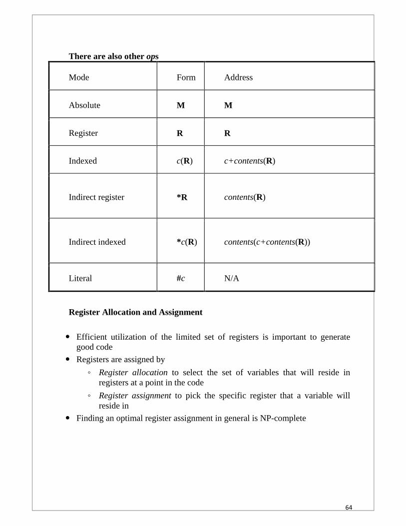
There are also other ops
Mode Form Address
Absolute M M
Register R R
Indexed c(R) c+contents(R)
Indirect register *R contents(R)
Indirect indexed *c(R) contents(c+contents(R))
Literal #c N/A
Register Allocation and Assignment
Efficient utilization of the limited set of registers is important to generategood code
Registers are assigned by
◦ Register allocation to select the set of variables that will reside inregisters at a point in the code
◦ Register assignment to pick the specific register that a variable willreside in
Finding an optimal register assignment in general is NP-complete

65
Example
Choice of Evaluation OrderWhen instructions are independent, their evaluation order can be changed

66
Conclusion:With help of given information and procedure we can implement code generation
phase.